Embed Size (px)
Citation preview
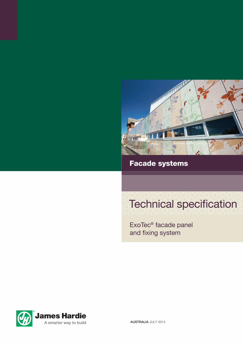
ExoTec® facade panel and fixing system
Technical specification
JHML112289
Facade systems
© Copyright 2012 James Hardie Australia Pty Ltd. ABN 12 084 635 558. ™ and ® denotes a trademark or registered mark owned by James Hardie Technology Limited
AUSTRALIA JULY 2014
1 APPLICATION AND SCOPE1.1 APPLICATIONThe James Hardie ExoTec® facade panel provides a durable, expressed joint panel appearance for building facades, fascias and soffits and together with the fixing system offers versatility to architects and builders. This is demonstrated by the variety of design styles that have been achieved including curved walls, panels installed vertically, horizontally or in a brick pattern. A wide range of decorative finishes can be used, from site-applied acrylic textures, to available factory-applied polyurethane plain colours and metallic finishes.
Both the 9mm and 12mm thick ExoTec facade panels may be used in wall facades, fascias and soffits.
If you are a specifier...or other responsible party for a project, ensure the information in these specifications is appropriate for the application you are planning and that you undertake specific design and detailing for areas which fall outside the scope of these specifications.
If you are an installer...Ensure that you follow the design, moisture management and associated details and material selection provided by the designer and the ExoTec facade panel and fixing system Installation Manual.
Make sure your information is up to dateWhen specifying or installing James Hardie products, ensure you have the current manual. Additional installation information, warranties and warnings are available at www.jameshardie.com.au or Ask James Hardie™ on 13 11 03.
1.2 SCOPEThis Technical Specification is intended for use by architects, designers and specifiers who may be involved with the specification of the ExoTec facade panel and fixing system. Further information relating to the installation of the ExoTec facade panel and fixing system is available in the ExoTec facade panel and fixing system Installation Manual.
This Technical Specification covers the use of the ExoTec facade panel and fixing system in a commercial facade application over steel girts, masonry and concrete walling. The Technical Specification also covers the use of the ExoTec facade panel and fixing system in a residential application over timber or steel framing. The ExoTec facade panel and fixing system can also provide an expressed joint panel appearance for building soffits.
All the information and details within both the James Hardie ExoTec facade panel and fixing system Technical Specification and the Installation Manual apply to both the 9mm and 12mm thick ExoTec facade panels. However, in curved facade walls only 9mm thick panels may be used depending on the curve radius, refer to Clause 10.1 for more information.
Both the 9mm and 12mm thick ExoTec facade panels may be used in wall facades, fascias and soffits.
1.3 SPECIfIC DESIgN AND DETAILINgFor use of the ExoTec facade panel and fixing system outside this published scope, the designer, architect or engineer must undertake specific design. James Hardie will not be responsible or warrant this product installed outside the scope of this Technical Specification.
For advice on designs outside the above scope contact Ask James Hardie™ on 13 11 03.
All dimensions shown are in millimetres unless noted otherwise. All Australian Standards referenced in this manual are current edition and must be complied with.
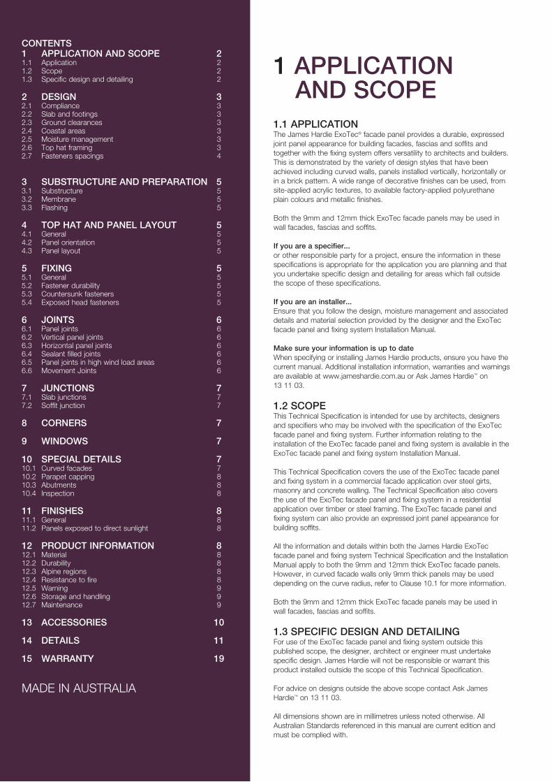
CONTENTS1 APPLICATION AND SCOPE 21.1 Application 21.2 Scope 21.3 Specific design and detailing 2
2 DESIgN 32.1 Compliance 32.2 Slab and footings 32.3 Ground clearances 32.4 Coastal areas 32.5 Moisture management 32.6 Top hat framing 32.7 Fasteners spacings 4
3 SUbSTRUCTURE AND PREPARATION 53.1 Substructure 53.2 Membrane 53.3 Flashing 5 4 TOP hAT AND PANEL LAyOUT 54.1 General 54.2 Panel orientation 54.3 Panel layout 5
5 fIxINg 55.1 General 55.2 Fastener durability 55.3 Countersunk fasteners 55.4 Exposed head fasteners 5 6 jOINTS 66.1 Panel joints 66.2 Vertical panel joints 66.3 Horizontal panel joints 66.4 Sealant filled joints 66.5 Panel joints in high wind load areas 66.6 Movement Joints 6
7 jUNCTIONS 77.1 Slab junctions 77.2 Soffit junction 7
8 CORNERS 7
9 wINDOwS 7
10 SPECIAL DETAILS 710.1 Curved facades 710.2 Parapet capping 810.3 Abutments 810.4 Inspection 8
11 fINIShES 811.1 General 811.2 Panels exposed to direct sunlight 8
12 PRODUCT INfORMATION 812.1 Material 812.2 Durability 812.3 Alpine regions 812.4 Resistance to fire 812.5 Warning 912.6 Storage and handling 912.7 Maintenance 9
13 ACCESSORIES 10
14 DETAILS 11
15 wARRANTy 19
MADE IN AUSTRALIA
EXOTEC FACADE PANEL AND FIXING SYSTEM TECHNICAL SPECIFICATION jULy 2014 3
2 DESIgN
2.1 COMPLIANCEAll design and construction must comply with the appropriate requirements of the current Building Code of Australia (BCA), regulations and standards.
2.2 SLAb AND fOOTINgSThe slab and footings on which the building is situated must be designed and certified by a qualified structural engineer according to all relevant codes, regulations and standards.
2.3 gROUND CLEARANCESInstall James Hardie external cladding with a minimum 150mm clearance to the earth on the exterior of the building or in accordance with local building codes if greater than 150mm is required. Also, maintain a minimum 50mm clearance between James Hardie external cladding and roofs, decks, paths, steps and driveways.
Adjacent finished grade must slope away from the building in accordance with local building codes, typically a minimum slope of 50mm minimum over the first metre.
Do not install external cladding in areas where it may remain in contact with standing water or debris.
2.4 COASTAL AREASIn coastal areas located within 1km of the shoreline or large expanses of salt water (eg. Port Phillip Bay, Sydney Harbour east of the Spit and Harbour Bridges, Swan River wet of the Narrows Bridge), one of the following is required:
n All horizontal and vertical expressed joints must be filled with a suitable sealant, refer to the sealant filled joints section in this specification.
n Where both the horizontal and vertical expressed joints are not filled, the joints and panels must be washed down twice a year.
On unprotected walls, rain will perform this washdown, but where walls are protected by soffits above, the washdown twice per year is a maintenance requirement.
2.5 MOISTURE MANAgEMENTThe ExoTec facade panel and fixing system acts as a weather shield. To achieve a particular level of weathertightness, the designer must determine the appropriate moisture management detailing for the project. The designer should consider the following matters when making that determination:
n It is the responsibility of the builders and designers to identify moisture related risks associated with any particular building design. It is the responsibility of the builder to ensure appropriate moisture management is provided during framed wall construction through effective use of flashings, sealants and vapour permeable membranes such as HardieWrap™ weather barrier, building wraps, vapour retarders and damp proof course. Before installing panels, all wall openings, penetrations, intersections, connections, window sills, heads and jambs must incorporate appropriate flashing and waterproofing. Materials, components and the installation practices that are used to manage moisture in framed wall construction must, at a minimum, comply with the requirements of relevant standards, building codes and the manufacturer’s specifications.
n Sealant at sheet joints must be installed where detailed in this literature. For wind pressures up to 4.0kPa, see Clauses 6.2 and 6.3. For pressures including and above 4.0kPa, both vertical and horizontal joints must be sealant filled, see Clause 6.5. Refer to Clause 6.4 for suitable joint sealant. Where sealant is exposed, refer to the sealant manufacturer for durability information.
n For high walls it may be necessary to provide flashing to drain the facade at one or more intermediate levels.
n The installation of smoke, vermin and other barriers must not restrict moisture from reaching flashings.
For information on membrane refer to Clause 3.2 of this manual.
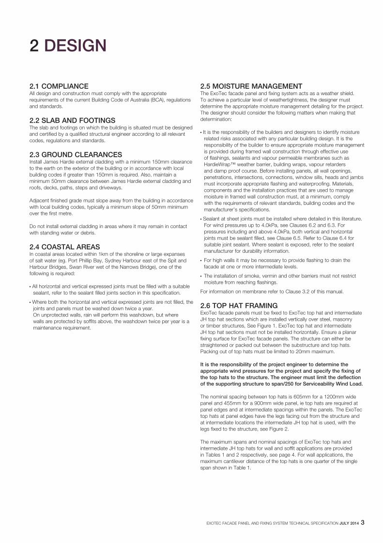
2.6 TOP hAT fRAMINgExoTec facade panels must be fixed to ExoTec top hat and intermediate JH top hat sections which are installed vertically over steel, masonry or timber structures, See Figure 1. ExoTec top hat and intermediate JH top hat sections must not be installed horizontally. Ensure a planar fixing surface for ExoTec facade panels. The structure can either be straightened or packed out between the substructure and top hats. Packing out of top hats must be limited to 20mm maximum.
It is the responsibility of the project engineer to determine the appropriate wind pressures for the project and specify the fixing of the top hats to the structure. The engineer must limit the deflection of the supporting structure to span/250 for Serviceability wind Load.
The nominal spacing between top hats is 605mm for a 1200mm wide panel and 455mm for a 900mm wide panel, ie top hats are required at panel edges and at intermediate spacings within the panels. The ExoTec top hats at panel edges have the legs facing out from the structure and at intermediate locations the intermediate JH top hat is used, with the legs fixed to the structure, see Figure 2.
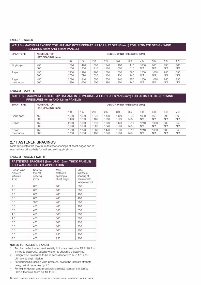
The maximum spans and nominal spacings of ExoTec top hats and intermediate JH top hats for wall and soffit applications are provided in Tables 1 and 2 respectively, see page 4. For wall applications, the maximum cantilever distance of the top hats is one quarter of the single span shown in Table 1.
4 EXOTEC FACADE PANEL AND FIXING SYSTEM TECHNICAL SPECIFICATION jULy 2014
TAbLE 1 - wALLS
TAbLE 2 - SOffITS
2.7 fASTENER SPACINgSTable 3 indicates the maximum fastener spacings at sheet edges and at intermediate JH top hats for wall and soffit applications.
TAbLE 3 - wALLS & SOffIT
NOTES TO TAbLES 1, 2 AND 31. Top hat deflection for serviceability limit state design to AS 1170.2 is
limited to span/250, except where * is shown it is span/180.2. Design wind pressures to be in accordance with AS 1170.2 for
ultimate strength design.3. For permissible design wind pressure, divide the ultimate strength
design wind pressures by 1.5. 4. For higher design wind pressures (ultimate), contact the James
Hardie technical team on 13 11 03.
wALLS - MAxIMUM ExOTEC TOP hAT AND INTERMEDIATE jh TOP hAT SPANS (mm) fOR ULTIMATE DESIgN wIND PRESSURES (9mm AND 12mm PANELS)
SPAN TyPE NOMINAL TOP DESIgN wIND PRESSURE (kPa) hAT SPACINg (mm)
1.0 1.5 2.0 2.5 3.0 3.5 4.0 5.0 6.0 7.0
Single span 450 1680 1470 1330 1240 1160 1110 1060 980 890 800 600 1530 1330 1210 1120 1060 1010 N/A N/A N/A N/A
2 span 450 2250 1970 1790 1660 1500 1380 1250 1080 950 830 600 2050 1790 1620 1400 1250 1140 N/A N/A N/A N/A
3 span 450 2080 1810 1650 1530 1440 1350 1250 1080 950 830 continuous 600 1890 1650 1500 1390 1250 1140 N/A N/A N/A N/A
SOffITS - MAxIMUM ExOTEC TOP hAT AND INTERMEDIATE jh TOP hAT SPANS (mm) fOR ULTIMATE DESIgN wIND PRESSURES (9mm AND 12mm PANELS)
SPAN TyPE NOMINAL TOP DESIgN wIND PRESSURE (kPa) hAT SPACINg (mm)
1.0 1.5 2.0 2.5 3.0 3.5 4.0 5.0 6.0 7.0
Single span 450 1560 1390 1270 1190 1120 1070 1030 960 900 860 600 1420 1260 1160 1080 1020 N/A N/A N/A N/A N/A
2 span 450 2090 1860 1710 1600 1440 1310 1210 1050 930 840 600 1900 1690 1520 1340 1200 N/A N/A N/A N/A N/A
3 span 450 1930 1720 1580 1470 1390 1310 1210 1050 930 840 continuous 600 1750 1560 1430 1340 1200 N/A N/A N/A N/A N/A
fASTENERS SPACINgS (9mm AND 12mm ThICk PANELS)fOR wALL AND SOffIT APPLICATION
Design wind Nominal Max. pressure top hat fasteners (ultimate) spacing spacing at (kPa) (mm) sheet edges (mm)
1.0 600 600 600
1.5 600 600 600
2.0 600 400 400
2.5 600 400 400
3.0 *600 400 300
3.0 450 400 400
3.5 450 350 350
4.0 450 300 300
4.5 450 300 300
5.0 450 300 250
5.5 450 300 250
6.0 450 300 200
6.5 400 250 200
7.0 400 250 200
Max. fasteners spacing at intermediate top hats (mm)
EXOTEC FACADE PANEL AND FIXING SYSTEM TECHNICAL SPECIFICATION jULy 2014 5
3 SUbSTRUCTURE AND PREPARATION3.1 SUbSTRUCTUREThe ExoTec top hat and intermediate JH top hat sections are installed vertically over steel girts, masonry, concrete walling and in residential applications over timber or steel framing. In a residential application, noggings between studs can be used as intermediate support for ExoTec top hat and intermediate JH top hat sections.
A qualified structural engineer must design the substructure and the connection between the substructure and the top hats.
3.2 hARDIEwRAP™ wEAThER bARRIERHardieWrap™ weather barrier must be installed behind Exotec® Facade Panel and Fixing system in accordance with the AS/NZS 4200.2 ‘Pliable building membranes and underlays – Installation’ and HardieWrap™Technical Data Sheet.
HardieWrap™ weather barrier delivers a tripleshield of protection to help against external weather penetration, internal condensation build-up andexternal heat penetration. Additionally, it enhances the wall thermal performance, please refer to www.jameshardie.com.au or www.accel.com.au for more information.
If using an alternate product in lieu of HardieWrap™ weather barrier, the designer must ensure that the product is fit for purpose and it has the following properties in accordance with AS/NZS 4200.1:
n Vapour barrier - low or medium n Water barrier - high
In hot humid areas of Australia, HardieWrap™ weather barrier may notbe suitable, refer to the building designer for a suitable membrane andAsk James Hardie® on 13 11 03.
Soft compressible insulation installed between the front of the wall studsand directly behind the external cladding can cause installation issues is thus not recommended.
3.3 fLAShINgAll wall openings, penetrations, intersections, connections, window sills, heads and jambs must be flashed prior to top hat and sheet installation. Refer to Clause 2.5 for moisture management requirements.
3.4 ThERMAL bREAkThe Building Code of Australia sections J1.5 and 3.12.1 volumes 1 and 2respectively, state for both residential and commercial buildings a thermal break with an R 0.2m² K/W must be installed behind external cladding where the cladding and internal lining make direct contact with the same metal frame. For more information on the HardieBreak™ Thermal Strip, please refer to the installation manual at www.jameshardie.com.au
NOTE The ExoTec façade panels are installed onto James Hardie™ top hat framing. It is recommended that you refer to the project certifier to determine if a thermal break is required. If required, it is recommend that the James Hardie™ HardieBreak™ thermal strip is installed vertically behind the top hats and in front of the HardieWrap™ weather barrier.
4 TOP hAT AND PANEL LAyOUT4.1 gENERALThe panel layout must be considered in conjunction with the building framing system, ie. the supporting top hat spacing must suit joints between panels and the design wind pressures, see Figure 1. Where construction joints occur in the structure, these must be carried through the top hats and panels, see Figure 9 and 12.
5 fIxINg5.1 gENERALExoTec panels must be fixed to ExoTec top hats and intermediate JH top hats with either:
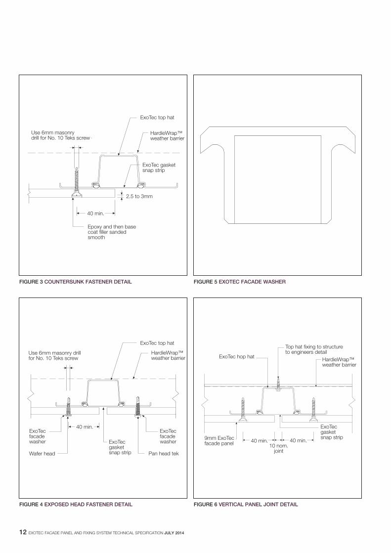
1. Countersunk screws flush finished with epoxy then with James Hardie base coat. Generally used with site-applied acrylic coatings. Refer to 5.2, 5.3 and Figure 3.
2. Exposed head screws, e.g. pan, wafer and hex heads. Used where pre-finished panels are installed. Exposed head fasteners may be colour coated to match panel finish. Exotec facade washers are recommended to be inserted between the panel and the fastener. Refer to 5.2, 5.4 and Figure 4.
5.2 fASTENER
Fasteners must have the appropriate level of durability required for the intended project. Fasteners must be fully compatible with all other materials that it is in contact with to ensure the durability and integrity of assembly. Contact fastener manufacturers for more information.
This is of particular importance in coastal areas, subject to salt spray and other corrosive environments. For details on maximum fastener spacings to top hats for design wind pressures, see Table 3 and Figure 1.
For fastener installation refer to fastener fixing section in the ExoTec facade panel and fixing system Installation Manual.
5.3 COUNTERSUNk fASTENERSRefer to 5.2 for fastener type. The screws are flush finished over with epoxy and then with James Hardie base coat. Use only proven epoxies for this application, ie Megapoxy P1 or Hilti CA 125. Where the temperature is below 15°C, use Hilti CA 273.
The screw head must be countersunk to a depth of 2.5mm to 3mm, see Figure 3.
5.4 ExPOSED hEAD fASTENERSRefer to 5.2 for fastener type. ExoTec facade washers are recommended to be inserted between the panel and the fastener, see Figure 4.
ExoTec panels must be pre-drilled with a 6mm masonry drill, which provides a 6.2mm to 6.3mm diameter hole.
fASTENER SELECTION
Countersunk fasteners Exposed head fasteners
ExoTec facade panel and fixing system
Countersunk head self drilling screw No.10x30mm (Class 3 minimum coating)
Exposed pan, wafer or hex head self drilling screw No. 10x25mm (Class 3 minimum coating)
4.2 PANEL ORIENTATIONThe panel must be installed with the distinctive white side facing the exterior of the structure. Where the back of the panel is open to the weather, refer to Clause 11.2 for specific requirements.
4.3 PANEL LAyOUTPanels are generally installed with a 10mm nominal vertical and horizontal expressed joint between adjacent panels, ie for 1200mm wide sheets and 10mm panel joints the grid dimension is 1210mm, see Figure 1. Vertical joints up to 20mm width can be formed, with additional care required at installation to ensure the panel edges cover the ExoTec gasket snap strip on both sides of the joint. A minimum vertical expressed joint of 6mm is allowed with care.
The vertical expressed joints may also be aligned or offset in a brick pattern layout.
NOTESWherever feasible, use stock panel sizes to minimise site cutting. See Table 7.
6 EXOTEC FACADE PANEL AND FIXING SYSTEM TECHNICAL SPECIFICATION jULy 2014
6 jOINTS
6.1 PANEL jOINTSPanels are generally installed with a nominal 10mm wide expressed joint between adjacent panels, vertically and horizontally. Vertical joints to 20mm width can be formed with the ExoTec facade panel and fixing system, with additional care required at installation to ensure the panel edges cover the ExoTec gasket snap strip on both sides of the joint.
6.2 VERTICAL PANEL jOINTSAt vertical panel joints, prior to fixing panels, the ExoTec gasket snap strip is fitted into ExoTec top hats by starting at one end and pushing into the ExoTec top hat along it’s length. Ends of the snap strips are butted together in top hats without any need for sealant.
The ExoTec gasket snap strip is a hi-tensile roll-formed steel section with rubber gaskets built in. It provides a primary weather shield for a design wind up to 4.0kPa, see Figure 6.
Panel edges are fixed directly to the ExoTec top hat without the need for packing at intermediate JH top hats.
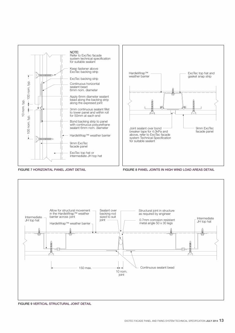
6.3 hORIzONTAL PANEL jOINTSAt horizontal panel joints, ExoTec backing strips are polyurethane sealant bonded to the back of panels to form a socket to which the next course of panels (or parapet capping) are fixed over, see Figure 7. The ExoTec backing strip is a 0.55mm base metal thickness (BMT) hi-tensile roll-formed steel section, with a pre-formed stop to keep it fitted against the back of the top edge of the lower panel.
6.4 SEALANT fILLED jOINTSWhere joints are required to be sealant filled, James Hardie Joint sealant and Bostik Seal ‘n’ flex are recommended. Where vertical joints are sealed, a bond breaker tape must be installed behind the sealant as outlined in Figure 8.
6.5 PANEL jOINTS IN hIgh wIND LOAD AREASFor design wind pressures including and above 4.0.kPa, horizontal and vertical joints must be continuously sealed with a joint sealant over a bond breaker tape. Refer to Clause 6.4 for suitable joint sealant.
NOTE Refer to sealant manufacturers’ instructions for application, safe use and clean up.
6.6 MOVEMENT jOINTS6.6.1 generalMovement joints are required to limit or remove stresses from the panels. Movement joints are provided by the 10mm expressed or sealant filled joints at the perimeter of the panels.
6.6.2 Vertical structural jointsVertical structural joints are required in the cladding to coincide with structural joints in the structure to accommodate the anticipated movement. The vertical structural joint is constructed as shown in Figure 9.
Vertical structural joints are also required where there is a discontinuity in the structure e.g. where two truss ends meet at a connection which allows movement.
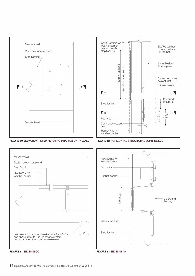
For details of abutment to masonry walls see Figures 10 and 11.
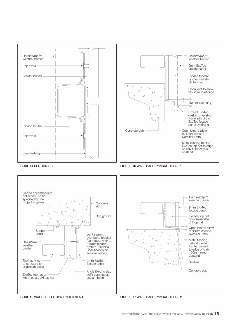
6.6.3 horizontal structural joints Horizontal structural joints are required at slab level where the framing supporting the top hats moves with the creep deflection in the slab. See Figures 12, 13 and 14 for details which can cater for this deflection. See Table 4 for the required height of the flashing upstand.
NOTE The project engineer is responsible for specifying the anticipated movement.
6.6.4 Construction joints Refer to Clause 10.3 Abutments for finishing panels against an existing building or another cladding system.
7 jUNCTIONS7.1 SLAb jUNCTIONS7.1.1 headWhere the cladding forms a junction with an exposed slab, the detail must provide for sufficient creep deflection in the slab. See Clause 6.6.3 for creep deflection where top hat crosses in front of the slab.
See Figure 15 for typical detail which can cater for this deflection.
7.1.2 baseThis junction can be treated in a number of ways, two of which are illustrated in Figures 16 and 17. See Table 4 for the required height of the flashing upstand.
TAbLE 4
NOTE For permissible design wind pressure, divide ULS wind pressure by 1.5.
NOTE It is essential that continuous flashing is provided behind the top hats at the base of walls to allow moisture to escape.
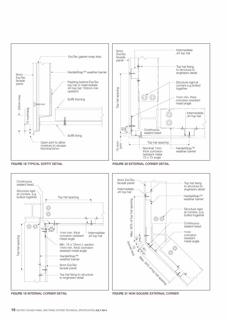
7.2 SOffIT jUNCTIONThere are many ways of detailing the soffit junction and it is important to ensure that a drip edge or groove is provided.A typical approach on how to install the soffit fascia junction is shown in Figure 18. Ensure the ExoTec gasket snap strip is installed continuously to the bottom of the fascia panel.
NOTEIt is essential that continuous flashing is provided behind the top hats at the base of the fascia to allow moisture to escape. See Table 4 for required height of the flashing upstand.
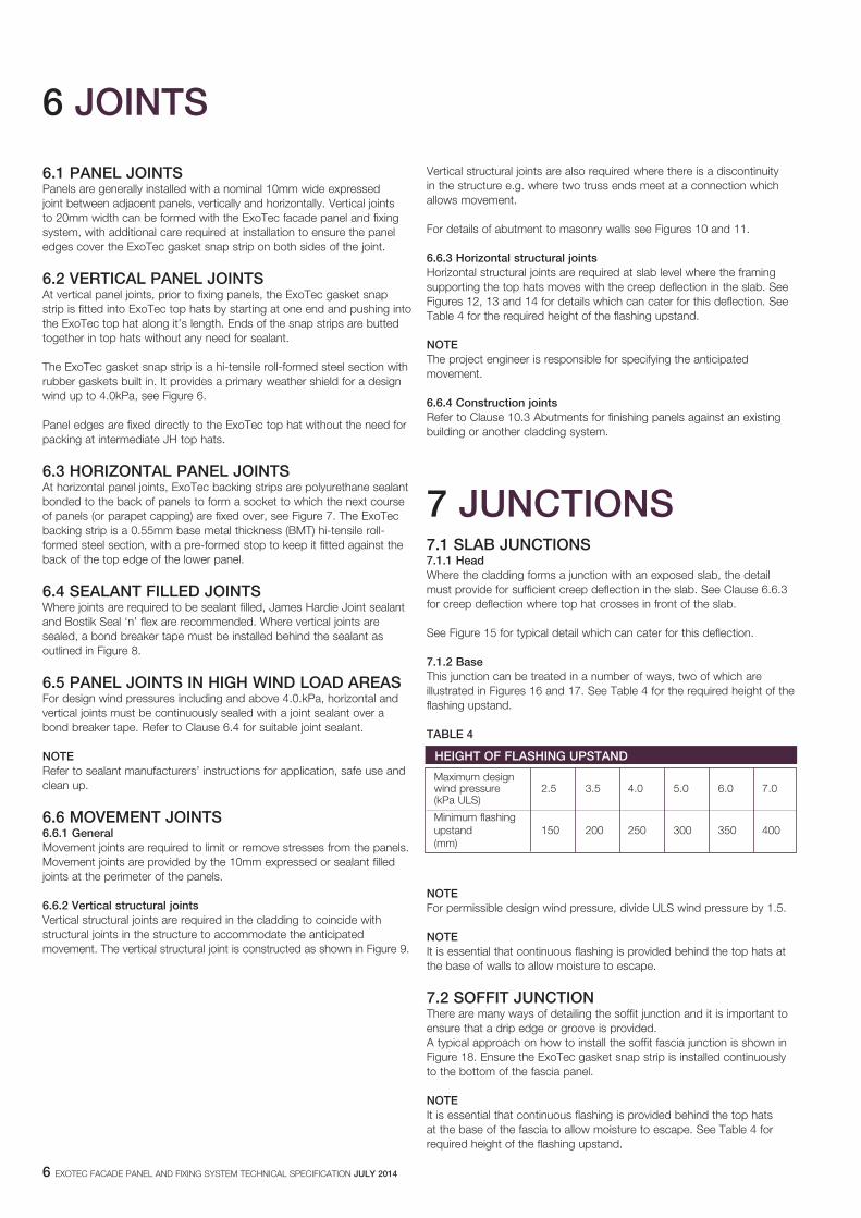
hEIghT Of fLAShINg UPSTAND
Maximum design wind pressure 2.5 3.5 4.0 5.0 6.0 7.0 (kPa ULS)
Minimum flashing upstand 150 200 250 300 350 400 (mm)
EXOTEC FACADE PANEL AND FIXING SYSTEM TECHNICAL SPECIFICATION jULy 2014 7
Corners can be readily constructed using a folded corrosion resistant metal angle behind the ExoTec facade panels, to support the corners see Figures 19, 20 and 21.
If a corner with a small radius is required, it can be made in Glass Reinforced Cement (GRC), supplied by other.
NOTE For ease of construction it may be preferred to fix the corner angle to one or both of the end top hats.
Figure 22 shows a typical external corner detail using Glass Reinforced Concrete (GRC) moulding.
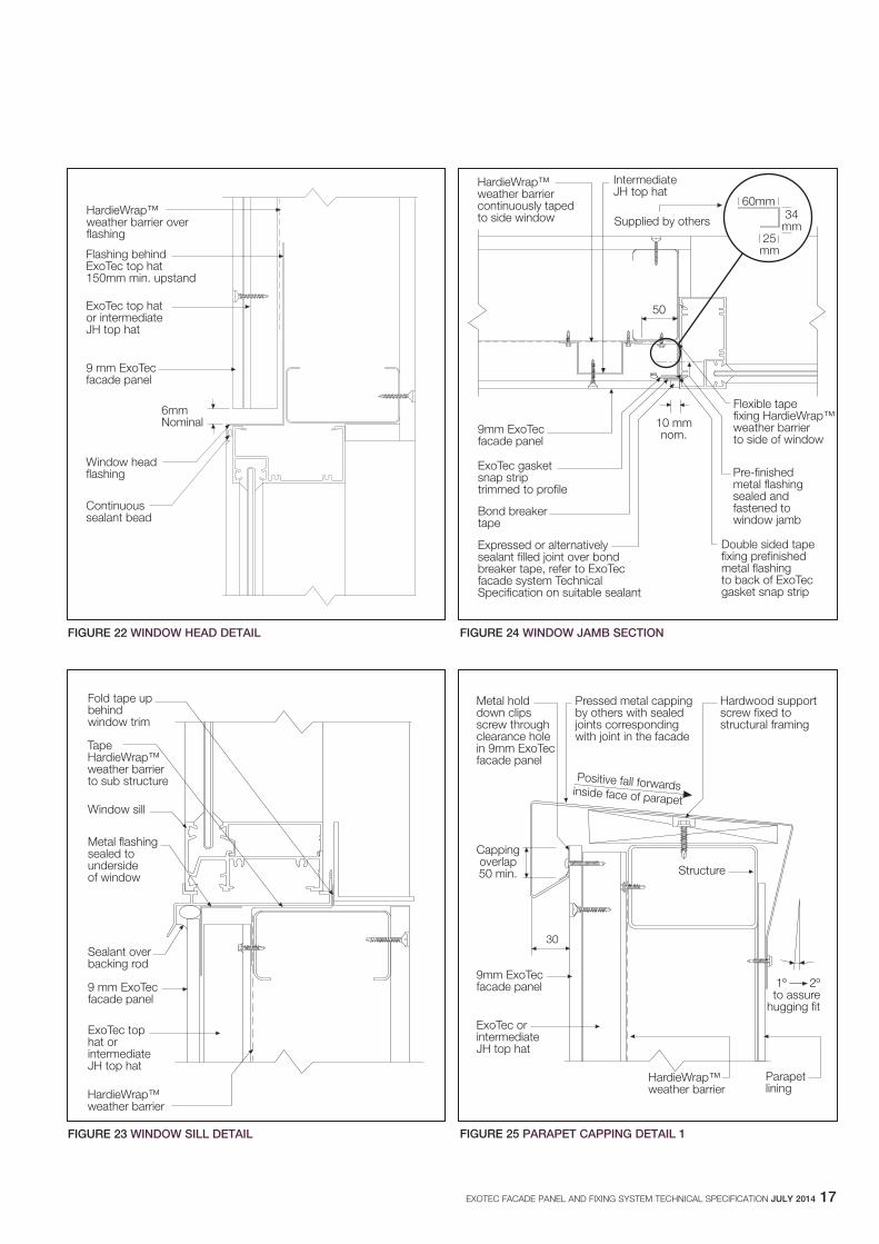
9 wINDOwSThe ExoTec facade panel and fixing system provides an opportunity to consider a range of alternative window treatments. The building designer, in conjunction with the window manufacturer, must consider the adequate weatherproofing of the window application, see Clause 2.5.Typical window details are shown in Figures 23 to 25. See Table 4 for the required height of the flashing upstand.
10 SPECIAL DETAILS10.1 CURVED fACADES10.1.1 for radii 10m or greaterWhere the curve radius is 10m or greater, 9mm thick panels are easily bent to the curve of the framing. Refer to Table 5 for maximum top hat spacing.
TAbLE 5
NOTES1. The closer the spacing of top hats, the less likely they will read
through as facets in the panels, particularly at small radii.2. 9mm thick panels may be able to be curved to a smaller radius, but
this is likely to overstress panels.
NOTE When fixing curved sheets, commence fixing from the centre ensuring full contact with top hats and work outwards to avoid “drumminess”. Particular care should be taken when curving panels to ensure the supports are on a true curve. If not, apart from poor appearance, there is a risk of locally over-stressing the panels and causing cracking.
Alternate materials and installation methods are available for radii less than specified above including glass reinforced cement (GRC) installed according to manufacturer’s specifications.
For further information on curved facades contact Ask James Hardie™ on 13 11 03.
10.2 PARAPET CAPPINgThe design of the metal parapet capping should aim to minimise staining of the cladding, as follows:
1. Ensure the top of the capping has a slope towards the roof.2. Provide a drip edge 30mm minimum out from the cladding face.3. In addition, all joints in capping should be sealed. Figure 25 shows a
typical design which meets these requirements. Refer to Table 6 for the required overlap.
TAbLE 6
NOTE For permissible design wind pressure, divide ULS wind pressure by 1.5.
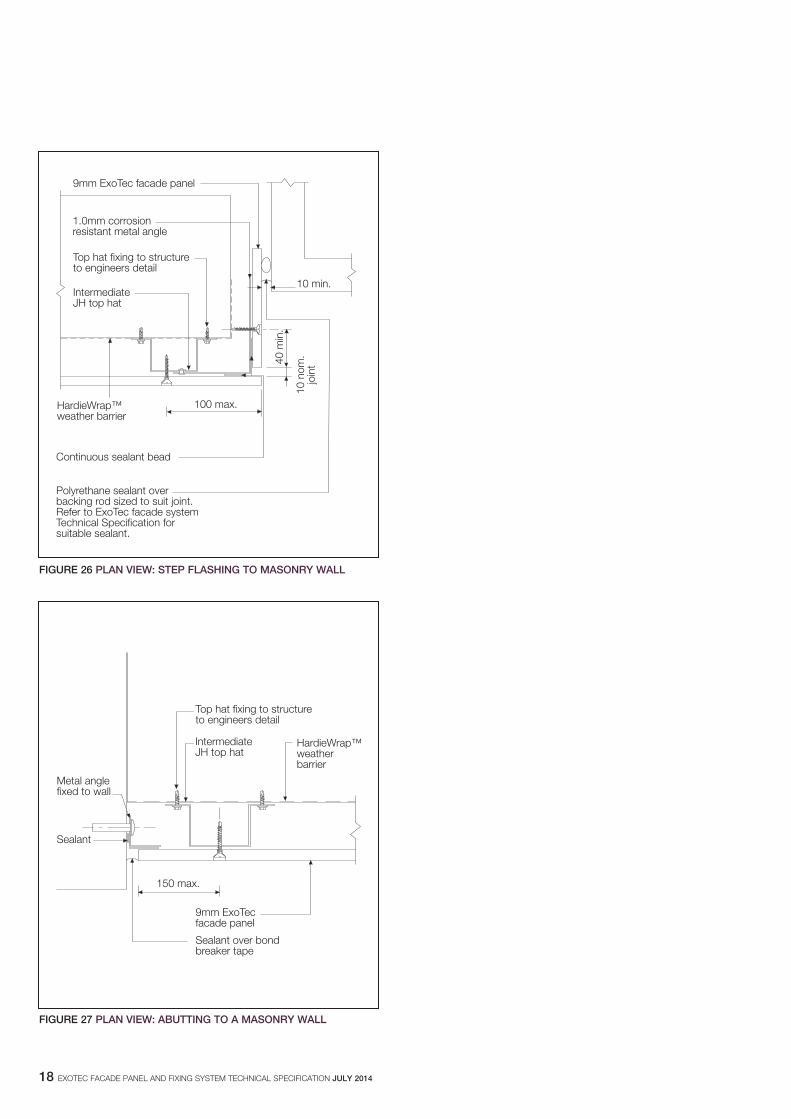
10.3 AbUTMENTSThere are numerous methods of finishing panels against another cladding system. Typical details are shown in Figures 26 and 27.
10.4 INSPECTIONAfter panels are installed and before painting, the facade/fascia should be inspected to ensure:
1. Required number and location of fixings are correct.2. Sealant has been applied where specified. Particular attention should
be given to the 3mm fillet of sealant between the backing strip and the panel along the full length of the horizontal backing strip socket.
3. The base coat applied over the epoxy and fastener has been sanded flush and smooth.
4. Minor damage to panel edges is filled, sanded smooth and painted as for cut edges, see Section 11.
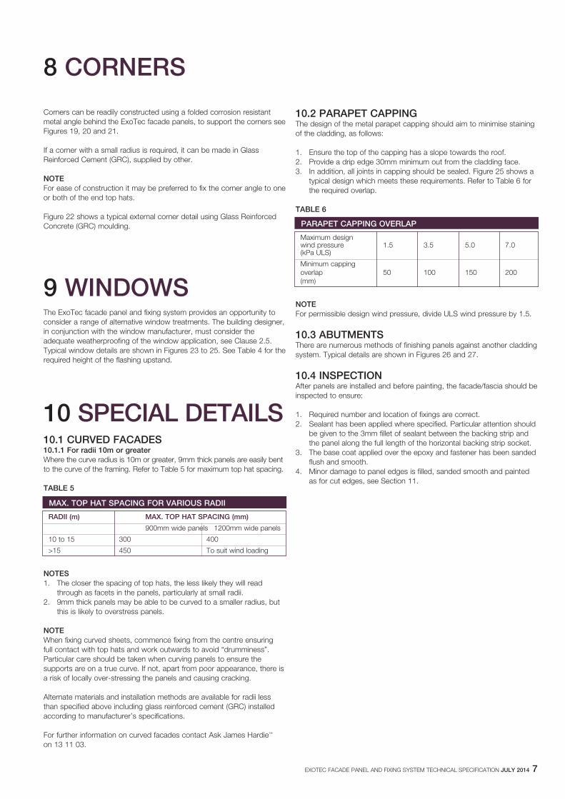
MAx. TOP hAT SPACINg fOR VARIOUS RADII
RADII (m) MAx. TOP hAT SPACINg (mm)
900mm wide panels 1200mm wide panels
10 to 15 300 400
>15 450 To suit wind loading
8 CORNERS
PARAPET CAPPINg OVERLAP
Maximum design wind pressure 1.5 3.5 5.0 7.0 (kPa ULS)
Minimum capping overlap 50 100 150 200 (mm)
8 EXOTEC FACADE PANEL AND FIXING SYSTEM TECHNICAL SPECIFICATION jULy 2014
11 fINIShES
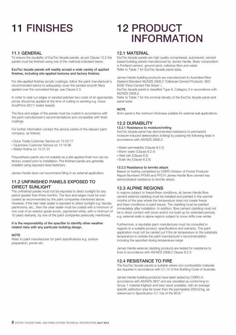
11.1 gENERALTo ensure the durability of ExoTec facade panels, as per Clause 12.2 the panels must be finished using one of the methods indicated below.
ExoTec facade panels will readily accept a wide variety of applied finishes, including site-applied textures and factory finishes.
For site-applied finishes (acrylic coatings), follow the paint manufacturer’s recommended advice to adequately cover the sanded smooth fillers applied over the concealed fixings, see Clause 5.3.
In order to seal cut edges or sanded patches two coats of an appropriate primer should be applied at the time of cutting or sanding e.g. Dulux AcraPrime 501/1 (water based).
The face and edges of the panels must be coated in accordance with the paint manufacturer’s recommendations and compatible with finish coatings.
For further information contact the service centre of the relevant paint company, as follows:
n Dulux Trade Customer Service on 13 23 77n Taubmans Customer Service on 13 16 86n Wattyl Hotline on 13 21 01
Polyurethane paints are not suitable as a site-applied finish but can be factory coated prior to installation. Pre-finished panels are generally installed using exposed head fasteners.
James Hardie does not recommend tiling in an external application.
11.2 UNfINIShED PANELS ExPOSED TO DIRECT SUNLIghT The unfinished panels must not be exposed to direct sunlight for any period greater than three months. The face and edges must be over-coated as recommended by the paint companies mentioned above. However, if the rear clear sealer is exposed to direct sunlight e.g. fascias, plantrooms, etc., then the clear sealer must be coated with a minimum of one coat of an exterior grade acrylic, pigmented white, with a minimum of 10 years warranty, by one of the paint companies previously mentioned.
It is the responsibility of the specifier to identify other weather related risks with any particular building design.
NOTERefer to paint manufacturer for paint specifications e.g. surface preparation, primer etc.
12.1 MATERIALExoTec facade panels are high quality compressed, autoclaved, cement based building panels manufactured by James Hardie. Basic composition is Portland cement, ground sand, cellulose fibre and water. Refer to Table 7 for ExoTec facade panel sizes.
James Hardie building products are manufactured to Australian/New Zealand Standard AS/NZS 2908.2 ‘Cellulose-Cement Products’ (ISO 8336 ‘Fibre-Cement Flat Sheet’ ).ExoTec facade panel is classified Type A, Category 3 in accordance with AS/NZS 2908.2.Refer to Table 7 for the nominal density of the ExoTec facade panel and panel sizes. NOTE 9mm panel is the minimum thickness suitable for external wall applications.
12.2 DURAbILITy12.2.1 Resistance to moisture/rotting ExoTec facade panel has demonstrated resistance to permanent moisture induced deterioration (rotting) by passing the following tests in accordance with AS/NZS 2908.2:
n Water permeability (Clause 8.2.2) n Warm water (Clause 8.2.4)n Heat rain (Clause 6.5)n Soak dry (Clause 8.2.5)
12.2.2 Resistance to termite attack Based on testing completed by CSIRO Division of Forest Products Report Numbers FP349 and FP274 James Hardie fibre cement has demonstrated resistance to termite attack.
12.3 ALPINE REgIONSIn regions subject to freeze/thaw conditions, all James Hardie fibrecement external cladding must be installed and painted in the warmermonths of the year where the temperature does not create freezeand thaw conditions or paint issues. The cladding must be paintedimmediately after installation. In addition, fibre cement cladding must notbe in direct contact with snow and/or ice build up for extended periods,e.g. external walls in alpine regions subject to snow drifts over winter.
Furthermore, a reputable paint manufacturer must be consulted inregards to a suitable product, specifications and warranty. The paintapplication must not be carried out if the air temperature or the substratetemperature is outside the paint manufacturer’s recommendationincluding the specified drying temperature range
James Hardie external cladding products are tested for resistance tofrost in accordance with AS/NZS 2908.2 Clause 8.2.3.
12.4 RESISTANCE TO fIREThe ExoTec facade panels is suitable where non-combustible materials are required in accordance with C1.12 of the Building Code of Australia.
James Hardie building products have been tested by CSIRO inaccordance with AS/NZS 3837 and are classified as conforming toGroup 1 material (highest and best result possible), with an averagespecific extinction area far lower than the permissible 250m2/kg, asreferenced in Specification C1.10a of the BCA.”
12 PRODUCT INfORMATION
EXOTEC FACADE PANEL AND FIXING SYSTEM TECHNICAL SPECIFICATION jULy 2014 9
12.4.2 fire rated walls Both one and two way fire rated wall systems are available with the ExoTec facade panel and fixing system. This will depend on the wall configuration and internal materials used. For more information refer to the ExoTec Facade Panel and fixing system FRL External Walls section of the James Hardie Fire and Acoustically rated walls application guide which is available at www.jameshardie.com.au, www.accel.com.au or Ask James Hardie™ on 13 11 03.
12.4.3 fire protective12mm thick ExoTec facade panel is suitable for use where the BCA requires the use of a fire protective material/lining (as deemed acceptable in the BCA Clause A1.1 Definitions – Fire Protective Covering).
12.5 wARNINg - DO NOT bREAThE DUST AND CUT ONLy IN wELL VENTILATED AREAJames Hardie products contain respirable crystalline silica which is considered by some international authorities to be a cause of cancer from some occupational sources. Breathing excessive amounts of respirable silica dust can also cause a disabling and potentially fatal lung disease called silicosis, and has been linked with other diseases. Some studies suggest smoking may increase these risks. During installation or handling: (1) work in outdoor areas with ample ventilation; (2) minimise dust when cutting by using either ‘score and snap’ knife, fibre cement shears or, where not feasible, use a HardieBlade® saw blade and dust-reducing circular saw attached to a HEPA vacuum; (3) warn others in the immediate area to avoid breathing dust; (4) wear a properly-fitted, approved dust mask or respirator (e.g. P1 or P2) in accordance with applicable government regulations and manufacturer instructions to further limit respirable silica exposures. During clean-up, use HEPA vacuums or wet cleanup methods - never dry sweep. For further information, refer to our installation instructions and Material Safety Data Sheets available at www.jameshardie.com.au. FAILURE TO ADHERE TO OUR WARNINGS, MATERIAL SAFETY DATA SHEETS, AND INSTALLATION INSTRUCTIONS MAY LEAD TO SERIOUS PERSONAL INJURY OR DEATH.
12.6 STORAgE AND hANDLINg To avoid damage, all materials should be stored with edges and corners of the panels protected from chipping.
Panels must be protected from rain during transport and storage. Panels must be laid flat undercover on a smooth level surface clear of the ground to avoid exposure to water or moisture etc. ExoTec facade panels are resistant to permanent water damage when installed as directed, and must only be installed in a dry state.
When handling ExoTec facade panels, carry panels on the edge taking care not to chip edges and corners.
Refer to the current installation manual for recommended safe working practices.
12.7 MAINTENANCEIt is the responsibility of the specifier to determine normal maintenance requirements.
The extent and nature of maintenance will depend on the geographical location and exposure of the building. As a guide, it is recommended that basic normal maintenance tasks shall include but not be limited to:
n In coastal areas, a six monthly washdown of expressed joints must be done as per Clause 2.4.
n Annual checks and maintenance for the exposed sealant (3mm fillet at horizontal joints, filled vertical and horizontal joints) referenced in Clauses 6.2, 6.3, 6.4, 6.5, 6.6, 7.1, 9, 11.1 and 11.2, must be done as required by the sealant manufacturer.
n Maintenance to painted surfaces must be carried in accordance with the paint manufacturer’s specification, see Clause 11.
n As required, clear debris build up against ExoTec facade panels.
n Maintain sealant as per manufacturer recommendations, to ensure weather seal.
n Clean out gutters, blocked pipes and overflows as required.
NOTE: Not all combinations of thicknesses, width and length are available ex stock, but are available to order. Check with James Hardie for availability of panel sizes.
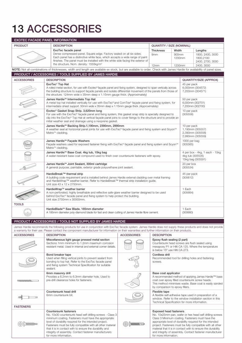
ExOTEC fACADE PANEL INfORMATION
PRODUCT DESCRIPTION qUANTITy / SIzE (NOMINAL)
ExoTec facade panel Dense compressed panel. Square edge. Factory sealed on all six sides. Each panel has a distinctive white face, which accepts a wide range of paint finishes. The panel must be installed with the white side facing the exterior of the structure. Nom. density: 1550kg/m3
PRODUCT / ACCESSORIES / TOOLS SUPPLIED by jAMES hARDIE ACCESSORIES DESCRIPTION qUANTITy/SIzE (APPROx)
ExoTec® Top hat 45 per pack A rolled metal section, for use with Exotec® façade panel and fixing system, designed to span vertically across 6,000mm (304572) the building structure to support façade panels and isolate differential movement of the panels from those of 7,200mm (304571) the structure. 124mm wide x 35mm deep x 1.15mm gauge thick. (Approximately)
james hardieTM Intermediate Top hat 50 per pack A metal top hat installed vertically for use with ExoTec® and ComTex® façade panel and fixing system, for 6,000mm (302701) intermediate sheet support. 50mm wide x 35mm deep x 1.15mm gauge thick. (Approximately) 7,200mm (302700)
Exotec® gasket Snap Strip. 3,620mm long 10 per pack For use with the ExoTec® façade panel and fixing system, this gasket snap strip is specially designed to (305556) clip into the ExoTec® Top Hat at vertical façade panel joins to cover fixings to the structure and to provide an initial weather seal and drainage using a neoprene gasket.
james hardieTM backing Strip.1,190mm, 2390mm, 2990mm 10 per pack A weather seal at horizontal panel joints for use with ExoTec® façade panel and fixing system and ScyonTM 1,190mm (305557) MatrixTM cladding. 2,390mm (305558) 2,990mm (305559)
james hardieTM façade washers 1000 per bag Façade washers used for exposed fastener fixing with ExoTec® façade panel and fixing system and ScyonTM (305565) MatrixTM cladding.
james hardieTM base Coat. 4kg tub, 15kg bag 4 per box - 4kg, 1 each - 15kg A water-resistant base coat compound used to finish over countersunk fasteners with epoxy. 4kg tub (305535) 15kg bag (305591)
james hardieTM joint Sealant, 300ml cartridge 20 per box A general purpose, paintable, exterior grade polyurethane joint sealant. (305534)
hardiebreak™ thermal strip 45 per pack A building code requirement and is installed behind James Hardie external cladding over metal framing (305612) and HardieWrap™ weather barrier. Refer to HardieBreak™ thermal strip installation guide. Unit size 43 x 12 x 2750mm.
hardiewrapTM weather barrier 1 Each A non-perforated, highly breathable and reflective safe-glare weather barrier designed to be used (305664) behind ExoTec® facade panel and fixing system to help protect the building. Unit size 2750mm x 30000mm.
TOOLS
hardiebladeTM Saw blade. 185mm diameter 1 Each A 185mm diameter poly-diamond blade for fast and clean cutting of James Hardie fibre cement. (300660)
PRODUCT / ACCESSORIES / TOOLS NOT SUPPLIED by jAMES hARDIE James Hardie recommends the following products for use in conjunction with ExoTec facade system. James Hardie does not supply these products and does not provide a warranty for their use. Please contact the component manufacturer for information on their warranties and further information on their products.
ACCESSORIES DESCRIPTION ACCESSORIES DESCRIPTION
Miscellaneous light gauge pressed metal section Epoxy flush sealing (2 part) Sections 1mm minimum to 1.2mm maximum corrosion Countersunk head screws are flush sealed using resistant metal. Used in internal and external corner details. mexapoxy P1 or Hilti CA 125. Where the temperature is below 15º use Hilti CA 273.
bond breaker tape Cordless drill Used when filling vertical joints to prevent sealant from Recommended tool for drilling holes and fastening bonding to top hat. Refer to the ExoTec facade panel screws. and fixing system Technical Specification for suitable sealant.
6mm masonry drill base coat applicator Provides a 6.2mm to 6.3mm diameter hole. Used to A recommended method of applying James Hardie™ base pre-drill clearance holes for fasteners. coat over epoxy filled countersunk screw heads. This method minimises waste. Base coat is easily sanded by comparison to epoxy fillers.
Countersunk head drill flexible tape 6mm countersunk bit. A flexible self-adhesive tape used in preparation of a window. Refer to the window installation section in this Technical Specification for more information.
fASTENERS
Countersunk fasteners Exposed head fasteners No. 10x30 countersunk head self drilling screws - Class 3 No. 10x25mm pan, wafer or hex head self drilling screws minimum coating. Fasteners must have the appropriate Class 3 Minimum coating. Fasteners must have the level of durability required for the intended project. appropriate level of durability required for the intended Fasteners must be fully compatible with all other material project. Fasteners must be fully compatible with all other that it is in contact with to ensure the durability and material that it is in contact with to ensure the durability integrity of assembly. Contact fastener manufacturers and integrity of assembly. Contact fastener manufacturer for more information. for more information.
13 ACCESSORIES
Thickness width Lengths9mm 900mm 1800, 2400, 3000 1200mm 1800,2100 2400, 2700, 300012mm 1200mm 2400, 3000
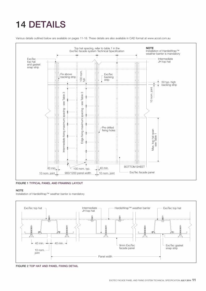
Various details outlined below are available on pages 11-18. These details are also available in CAD format at www.accel.com.au
NOTE Installation of HardieWrap™ weather barrier is mandatory
EXOTEC FACADE PANEL AND FIXING SYSTEM TECHNICAL SPECIFICATION jULy 2014 11
14 DETAILS
40 min.
Top hat spacing, refer to table 1 in theExoTec facade system Technical Specification
ExoTectop hatand gasketsnap strip
IntermediateJH top hat
Fix abovebacking strip
100
nom
.ty
p50 typ. highbacking strip
10 n
om. j
oint
Max
. top
hat
spa
nse
e Ta
ble
1
BOTTOM SHEET
NOTEInstallation of HardieWrap™weather barrier is mandatory
10 nom. joint
100 nom. typ.
900/1200 panel width
Inte
rmed
iate
fixi
ng m
axim
um s
paci
ng -
see
Tab
le 3
40 min.
10 nom. joint
Edg
e fix
ing
max
imum
spa
cing
- s
ee T
able
3
ExoTecbackingstrip
Pre drilledfixing holes
ExoTec facade panel
ExoTec top hat IntermediateJH top hat
ExoTec top hat
ExoTec gasketsnap strip
9mm ExoTecfacade panel
Panel width
40 min.
10 nom.joint
40 min.
HardieWrap™ weather barrier
fIgURE 1 TyPICAL PANEL AND fRAMINg LAyOUT
fIgURE 2 TOP hAT AND PANEL fIxINg DETAIL
12 EXOTEC FACADE PANEL AND FIXING SYSTEM TECHNICAL SPECIFICATION jULy 2014
Use 6mm masonrydrill for No. 10 Teks screw
ExoTec top hat
ExoTec gasketsnap strip
2.5 to 3mm
40 min.
Epoxy and then basecoat filler sandedsmooth
HardieWrap™ weather barrier
fIgURE 3 COUNTERSUNk fASTENER DETAIL fIgURE 5 ExOTEC fACADE wAShER
fIgURE 4 ExPOSED hEAD fASTENER DETAIL
Use 6mm masonry drillfor No. 10 Teks screw
ExoTec top hat
ExoTecfacadewasher
Wafer head
40 min.
ExoTecgasketsnap strip Pan head tek
ExoTecfacadewasher
HardieWrap™ weather barrier ExoTec hop hat
Top hat fixing to structureto engineers detail
40 min.10 nom.
joint
40 min.9mm ExoTecfacade panel
ExoTecgasketsnap strip
HardieWrap™ weather barrier
fIgURE 6 VERTICAL PANEL jOINT DETAIL
EXOTEC FACADE PANEL AND FIXING SYSTEM TECHNICAL SPECIFICATION jULy 2014 13
Keep fastener aboveExoTec backing strip
ExoTec backing strip
Continuous horizontalsealant bead6mm nom. diameter
Apply 6mm diameter sealantbead along the backing stripalong the expresed joint
3mm continuous sealant filletto lower panel and within rollfor 50mm at each end
Bond backing strip to panelwith continuous polyurethanesealant 6mm nom. diameter
9mm ExoTecfacade panel
ExoTec top hat orintermediate JH top hat
NOTE:Refer to ExoTec facadesystem technical specificationfor suitable sealant
100
nom
. typ
.10
0 no
m. t
yp.10
nom
. typ
.
HardieWrap™ weather barrier
fIgURE 7 hORIzONTAL PANEL jOINT DETAIL
IntermediateJH top hat
Allow for structural movementin the HardieWrap™ weatherbarrier across joint
Sealant overbacking rodsized to suitjoint
Structural joint in structureas required by engineer
0.7mm corrosion resistantmetal angle 50 x 30 legs
IntermediateJH top hat
Continuous sealant bead10 nom.
joint
150 max.
HardieWrap™ weather barrier
fIgURE 8 PANEL jOINTS IN hIgh wIND LOAD AREAS DETAIL
ExoTec top hat andgasket snap strip
Joint sealant over bondbreaker tape for 4.0kPa andabove, refer to ExoTec facadesystem Technical Specificationfor suitable sealant
9mm ExoTecfacade panel
HardieWrap™ weather barrier
fIgURE 9 VERTICAL STRUCTURAL jOINT DETAIL
14 EXOTEC FACADE PANEL AND FIXING SYSTEM TECHNICAL SPECIFICATION jULy 2014
Masonry wall
Purpose made stop end
Step flashing
Sealant bead
C C
fIgURE 11 SECTION CC
Masonry wall
Sealant around stop end
Step flashing
Joint sealant over bond breaker tape for 4.0kPaand above, refer to ExoTec facade systemTechnical Specification on suitable sealant.
10
HardieWrap™ weather barrier
fIgURE 12 hORIzONTAL STRUCTURAL jOINT DETAIL
Continuous sealantbead
Pop rivet
Step flashing
Insert HardieWrap™weather barrierover and understep flashing
Spe
cifie
d cr
eep
+5m
m
150
min
. ups
tand
ExoTec top hator intermediateJH top hat
9mm ExoTecfacade panel
3mm continuoussealant fillet
10 min. overlap
Specifiedcreep +5
100nom.
10
20
10
A
B
A
B
HardieWrap™ weather barrier
fIgURE 13 SECTION AA
Step flashing
Pop rivets
Sealant beads
ExoTec top hat
40m
m la
p
Colorbondflashing
HardieWrap™ weather barrier
fIgURE 10 ELEVATION - STEP fLAShINg INTO MASONRy wALL
EXOTEC FACADE PANEL AND FIXING SYSTEM TECHNICAL SPECIFICATION jULy 2014 15
fIgURE 14 SECTION bb
Step flashing
Pop rivets
Sealant beads
ExoTec top hat
Pop rivets
HardieWrap™ weather barrier
fIgURE 15 wALL DEfLECTION UNDER SLAb
Supportangle
Gap to accommodatedeflection - to bespecified by theproject engineer
Top hat fixingto structure toengineers detail
Drip groove
Concreteslab
Joint sealantover bond breakerfoam tape, refer toExoTec facadesystem TechnicalSpecification onsuitable sealant
Angle fixed to slabsoffit continuoussealant bead
9mm ExoTecfacade panel
ExoTec top hat orintermediate JH top hat
HardieWrap™ weatherbarrier
HardieWrap™weather barrier
9mm ExoTecfacade panel
ExoTec top hator intermediateJH top hat
Open joint to allowmoisture to escape
50mm overhang
Extend ExoTecgasket snap stripthe length of theExoTec facadepanel overhang
Metal flashing behindExoTec top hat to edgeof slab 150mm min.upstand
Concrete slab Open joint to allowmoisture escapeNominal 6mm
fIgURE 17 wALL bASE TyPICAL DETAIL 2
fIgURE 16 wALL bASE TyPICAL DETAIL 1
9mm ExoTecfacade panel
ExoTec top hator intermediateJH top hat
Open joint to allowmoisutre escapeNominal 6mm
Metal flashingbehind ExoTectop hat sealedto edge of slab150mm min.upstand
Sealant
Concrete slab
HardieWrap™ weather barrier
16 EXOTEC FACADE PANEL AND FIXING SYSTEM TECHNICAL SPECIFICATION jULy 2014
Flashing behind ExoTectop hat or intermediateJH top hat 150mm min.upstand
Soffit framing
Soffit lining
9mmExoTecfacadepanel
15 o
verh
ang
Open joint to allowmoisture to escapeNominal 6mm
ExoTec gasket snap strip
50m
m m
ax.
HardieWrap™ weather barrier
fIgURE 19 INTERNAL CORNER DETAIL
IntermediateJH top hat
Structure rigidat corners, e.g.bolted together
9mm ExoTecfacade panel
1mm min. thickcorrosion resistantmetal angle
Continuoussealant bead
40min.
Top hat fixing to structureto engineers detail
Top
hat s
paci
ng
Min. 75 x 75mm L section1mm min. thick corrosionresistant metal angle
Top hat spacing
10
HardieWrap™ weather barrier
fIgURE 20 ExTERNAL CORNER DETAIL
40 min
.
10 n
om.
join
tTo
p ha
t spa
cing
Top hat spacing
Nominal 1mmthick corrosionresistant metal75 x 75 angle
IntermediateJH top hat
Top hat fixingto structure toengineers detail
Continuoussealant bead
1mm min. thickcorrosion resistantmetal angle
Structure rigid atcorners e.g boltedtogether
9mmExoTecfacadepanel
IntermediateJH top hat
HardieWrap™ weather barrier
fIgURE 21 NON SqUARE ExTERNAL CORNER
Top hat fixingto structure toengineers detailIntermediate
JH top hat
Structure rigidat corners, e.g.bolted together
9mm ExoTecfacade panel
1mmcorrosionresistantmetal angle
Continuoussealant bead
Max. 50%
of top hat spacing
40min.
12
Across face
40 min
.Max
. 50%
of t
op h
at s
paci
ng
HardieWrap™ weather barrier
fIgURE 18 TyPICAL SOffIT DETAIL
EXOTEC FACADE PANEL AND FIXING SYSTEM TECHNICAL SPECIFICATION jULy 2014 17
fIgURE 22 wINDOw hEAD DETAIL
Continuoussealant bead
Flashing behindExoTec top hat150mm min. upstand
Window headflashing
ExoTec top hator intermediateJH top hat
9 mm ExoTecfacade panel
6mmNominal
HardieWrap™ weather barrier overflashing
fIgURE 23 wINDOw SILL DETAIL
Fold tape upbehindwindow trim
Window sill
Metal flashingsealed toundersideof window
Sealant overbacking rod
ExoTec tophat orintermediateJH top hat
9 mm ExoTecfacade panel
HardieWrap™ weather barrier
Tape HardieWrap™ weather barrierto sub structure
fIgURE 24 wINDOw jAMb SECTION
9mm ExoTecfacade panel
ExoTec gasketsnap striptrimmed to profile
Bond breakertape
Pre-finishedmetal flashingsealed andfastened towindow jamb
Double sided tapefixing prefinishedmetal flashingto back of ExoTecgasket snap strip
Expressed or alternativelysealant filled joint over bondbreaker tape, refer to ExoTecfacade system TechnicalSpecification on suitable sealant
10 mmnom.
IntermediateJH top hat
50
Supplied by others
60mm34mm
25mm
HardieWrap™ weather barriercontinuously tapedto side window
Flexible tapefixing HardieWrap™ weather barrierto side of window
Pressed metal cappingby others with sealedjoints correspondingwith joint in the facade
Metal holddown clipsscrew throughclearance holein 9mm ExoTecfacade panel
ExoTec orintermediateJH top hat
9mm ExoTecfacade panel
Positive fall forwardsinside face of parapet
Cappingoverlap50 min.
30
Parapetlining
Structure
Hardwood supportscrew fixed tostructural framing
HardieWrap™ weather barrier
fIgURE 25 PARAPET CAPPINg DETAIL 1
18 EXOTEC FACADE PANEL AND FIXING SYSTEM TECHNICAL SPECIFICATION jULy 2014
Sealant
Metal anglefixed to wall
Top hat fixing to structureto engineers detail
IntermediateJH top hat
150 max.
9mm ExoTecfacade panel
Sealant over bondbreaker tape
HardieWrap™ weather barrier
fIgURE 26 PLAN VIEw: STEP fLAShINg TO MASONRy wALL
100 max.
1.0mm corrosionresistant metal angle
Top hat fixing to structureto engineers detail
IntermediateJH top hat
Polyrethane sealant overbacking rod sized to suit joint.Refer to ExoTec facade systemTechnical Specification forsuitable sealant.
9mm ExoTec facade panel
Continuous sealant bead
10 n
om.
join
t40 m
in.
10 min.
HardieWrap™ weather barrier
fIgURE 27 PLAN VIEw: AbUTTINg TO A MASONRy wALL
EXOTEC FACADE PANEL AND FIXING SYSTEM TECHNICAL SPECIFICATION jULy 2014 19
15 wARRANTy
ExoTec® facade panel
10 yEAR wARRANTy
january 2012 James Hardie Australia Pty Limited (“James Hardie”) warrants to the first purchaser of ExoTec® facade panel (Product) from James Hardie and the last purchaser of the Product prior to installation that, subject to compliance with the Conditions of Warranty below:
- for a period of 10 years from the date of purchase, the Product will be free from defects due to defective factory workmanship or materials; and - for a period of 10 years from the date of purchase, the Product will be resistant to damage from cracking, moisture, rotting, fire and termites to the extent set out in James Hardie’s relevant published literature current at the time of installation; and - for a period of 12 months from the date of purchase that the accessories supplied by James Hardie will be free from defects due to defective factory workmanship or materials.
For the purposes of this warranty, a “defect” in respect of the Product means a non-compliance with AS/NZS 2908.2:2000 Cellulose-cement products - Flat sheet.
CONDITIONS Of wARRANTy This warranty is strictly subject to the following conditions:
(a) James Hardie will not be liable for breach of this warranty unless the claimant provides proof of purchase of the Product and makes a written claim to James Hardie at the address set out below, either within 30 days after the defect would have become reasonably apparent or, if the defect was reasonably apparent prior to installation, then the claim must be made prior to installation.
(b) the Product is subject to natural variation in finish as part of the manufacturing process. The builder/installer must ensure the Product meets aesthetic requirements before installation. Subject to the terms of this warranty, after installation of the Product, James Hardie is not liable for claims arising from aesthetic surface variations if such variations were, or would upon reasonable inspection have been, apparent prior to installation;
(c) this warranty cannot be relied upon by any other person and is not transferable;
(d) the Product must be installed and maintained strictly in accordance with the relevant James Hardie literature current at the time of installation and must be installed in conjunction with the components or products specified in the literature. To obtain copies of such literature go to or contact Ask James Hardie™ on 13 11 03. Further, all other products, including coating and jointing systems, applied to or used in conjunction with the Product must be applied or installed and maintained strictly in accordance with the relevant manufacturer’s instructions and good trade practice;
(e) the project must be designed and constructed in strict compliance with all relevant provisions of the current Building Code of Australia, regulations and standards;
(f) if the claimant chooses to rely upon this warranty then the claimant’s sole remedy under this warranty for breach of this warranty is (at James Hardie’s option) that James Hardie will either supply replacement Product, rectify the affected Product or pay for the cost of the replacement or rectification of the affected Product;
(g) In the circumstances where the Australian Consumer Law does not apply in respect of the purchase of the Product, James Hardie will not be liable for any losses or damages (whether direct or indirect) including property damage or personal injury, consequential loss, economic loss or loss of profits, arising in contract or negligence or howsoever arising. Without limiting the foregoing, James Hardie will not be liable for any claims, damages or defects arising from or in any way attributable to poor workmanship, poor
design or detailing, settlement or structural movement and/or movement of materials to which the Product is attached, incorrect design of the structure, acts of God including but not limited to earthquakes, cyclones, floods or other severe weather conditions or unusual climatic conditions, efflorescence or performance of paint/coatings applied to the Product, normal wear and tear, growth of mould, mildew, fungi, bacteria, or any organism on any Product surface or Product (whether on the exposed or unexposed surfaces);
(h) In the circumstances where the Australian Consumer Law does not apply in respect of the purchase of the Product, all warranties, conditions, liabilities and obligations other than those specified in this warranty are excluded to the fullest extent allowed by law;
(i) If meeting a claim under this warranty involves re-coating of Product, there may be slight colour differences between the original and replacement Product due to the effects of weathering and variations in materials over time and James Hardie is not liable for any such colour differences;
(j) In the circumstances where the Australian Consumer Law does not apply in respect of the purchase of the Product and therefore to this warranty, all expenses incurred as a result of claiming under this warranty are to be borne by the claimant.
(k) In the circumstances where the Australian Consumer Law does apply in respect of the purchase of the Product and therefore to this warranty, if James Hardie accepts or it is determined by James Hardie that the claimant has a valid claim under this warranty, James Hardie will bear the claimant’s reasonable costs of claiming under this warranty. The claimant is responsible for all other costs of claiming under this warranty. All claims for such costs are to be notified to James Hardie at the address outlined below within 21 days from when the claimant first makes a claim under this warranty.
DISCLAIMER The recommendations in James Hardie’s literature are based on good building practice but are not an exhaustive statement of all relevant information and are subject to conditions (d), (e), (g) and (h) above. Further, as the successful performance of the relevant system depends on numerous factors outside the control of James Hardie (e.g. quality of workmanship and design), James Hardie shall not be liable for the recommendations in that literature and the performance of the relevant system, including its suitability for any purpose or ability to satisfy the relevant provisions of the Building Code of Australia, regulations and standards.
IMPORTANT NOTE If you acquire goods manufactured by James Hardie as a consumer according to the Australian Consumer Law, our goods come with guarantees that cannot be excluded under the Australian Consumer Law. You are entitled to a replacement or refund for a major failure and compensation for any other reasonably foreseeable loss or damage. You are also entitled to have the goods repaired or replaced if the goods fail to be of acceptable quality and the failure does not amount to a major failure.
Any rights a consumer may have under this warranty are in addition to other rights and remedies of a consumer under a law in relation to the goods to which this warranty relates. Nothing in this document shall exclude or modify any legal rights a customer may have under the Australian Consumer Law or otherwise which cannot be excluded or modified at law.
Contact details if you wish to make a claim under this warranty: For more information or to make a claim under this warranty please Ask James Hardie™ on 13 11 03, visit www.jameshardie.com.au or www.accel.com.au, email James Hardie via our website or write to James Hardie at: james hardie Australia Pty Ltd 10 Colquhoun Street Rosehill NSw 2142 PO box 70 Parramatta NSw 2124
© Copyright 2012 James Hardie Australia Pty Ltd. ABN 12 084 635 558. ™ and ® denotes a trademark or registered mark owned by James Hardie Technology Limited

ExoTec® facade panel and fixing system
Technical specification
JHML112289
Facade systems
© Copyright 2012 James Hardie Australia Pty Ltd. ABN 12 084 635 558. ™ and ® denotes a trademark or registered mark owned by James Hardie Technology Limited