Embed Size (px)
Citation preview
Fabrication & Repair ManualFor EXTREN® Fiberglass Structural Shapes
— 2 —
TABLE OF CONTENTS
FABRICATION & REPAIR MANUAL
Subject Page
Preface .................................................................................. 2
Fabrication
Recommended General Fabrication Practices ...................... 3 Sawing or Cutting .................................................................. 4 Punching ............................................................................... 5 Shearing ................................................................................ 5 Drilling ................................................................................... 5 Routing .................................................................................. 6 Turning ................................................................................... 6 Grinding ................................................................................. 6 Sanding ................................................................................. 6 Threading & Tapping ............................................................. 6 Mechanical Fastening .........................................................6-7 Adhesive Fastening ............................................................... 8 Taping of Joints ..................................................................... 9 Painting & Finishing ............................................................. 10
Repair
Quick Repair Guide ............................................................. 10 Cleaning .............................................................................. 11 Resin Sealing ...................................................................... 11 Splicing ................................................................................ 12 Resin Filling ......................................................................... 14 Burns ................................................................................... 15 Glass Lay-up ....................................................................... 15 Hole Filling ........................................................................... 16
— 3 —
PREFACEEXTREN® structural shapes are designed to provide an excellent combination of mechanical properties, electrical properties and
weather resistance. No accurate estimate of the usable life of pultruded shapes exists, but Strongwell structural shapes have been in continuous service in many applications in excess of twenty (25) years.
This manual presents many of the fabrication techniques currently being used in working with EXTREN®. Working with EXTREN® is somewhat similar to working with wood, but there are some differences in cutting and fastening. These differences will be presented in detail. This manual will also present the cleaning, inspection, maintenance and repair of EXTREN® structural shapes. The procedures are applicable whether or not the structural shape has been fabricated into a special construction or is installed as received. Under normal operating conditions, problems requiring extensive repair to the EXTREN® structural shapes should not occur. The procedures described are also generally applicable for the fabrication and repair of Strongwell custom shapes.
The material herein is presented in good faith to serve as a guide for EXTREN® customers. All of the repair materials mentioned in this manual can be obtained locally through EXTREN® distributors or from Strongwell directly.
FABRICATIONRecommended General Fabrication Practices
1. Observe common safety precautions. For example, the operator of a circular power saw should wear safety glasses to protect his eyes.
2. A coverall or shop coat will add to the operator's comfort during sawing, machining or sanding operations. Although the dust created is non-toxic and presents no serious health hazard, it can cause skin irritation. The amount of irritant will vary from person to person and can be reduced or eliminated by use of a protective cream.
3. Machine ways and other friction-producing areas should be cleaned frequently. The combination of grease and fiberglass chips can rapidly become a damaging abrasive if allowed to accumulate.
4. Avoid excessive pressure when sawing, drilling, routing, etc. Too much force can rapidly dull the tool. (Diamond or carbide grit edge saw blades, carbide tip drill bits and carbide router bits are recommended.)
5. Do not generate excessive heat in any machining operation. Excessive heat softens the bonding resin in the fiberglass — resulting in a ragged rather than a clean-cut edge. Excessive heat can also burn resin and glass.
6. Support the fiberglass material rigidly during cutting operations. Shifting may cause chipping at the cut edges. Proper support will also prevent any warping.
7. Consider carefully the use and design of fastening devices for mechanical connections.
8. For adhesive fastening, prepare the surface properly for bonding prior to the application of the adhesive.
9. The strongest connection of high reliability can be made by using a combination of mechanical fasteners with adhesives.
10. If required, always touch-up or seal any cut surfaces or edges of the fiberglass shape before reporting the job complete.
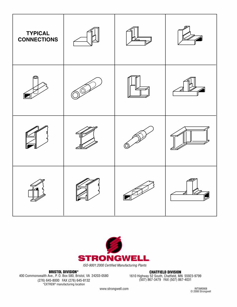
11. Examples of typical connections are shown on back cover.
FABRICATION & REPAIR MANUAL
— 4 —
MACHINING
Sawing or CuttingAlways provide adequate support to keep the material from
shifting when making a cut. Without adequate support, fiberglass reinforced profiles will chip.
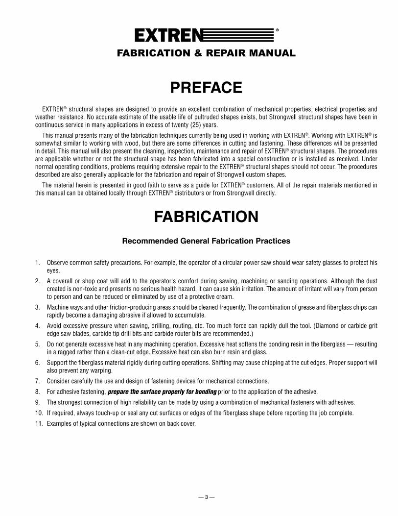
In cutting operations, use light, evenly applied pressure. Heavy pressure tends to clog the blade with dust particles and shorten the cutting life of the blade. Cutting speed is a critical variable. If the part edges begin to fray or turn black, slow the cutting speed.
Water cooling is desirable when many pieces or thick cross sections are being sawed. With cooling, cutting speeds increase, smoother cuts result, and dust is often eliminated. However, water contaminate disposal is a consideration.
Deciding whether to saw EXTREN® structurals with a hand or power saw depends, among other things, on the quantity being cut. When sawing relatively few pieces, a disposable-blade hacksaw (24 to 32 teeth per inch) is suitable. Although an ordinary carpenter's saw can be used, frequent resharpening makes this tool less desirable. Remington grit edge blades can also be used in a hacksaw.
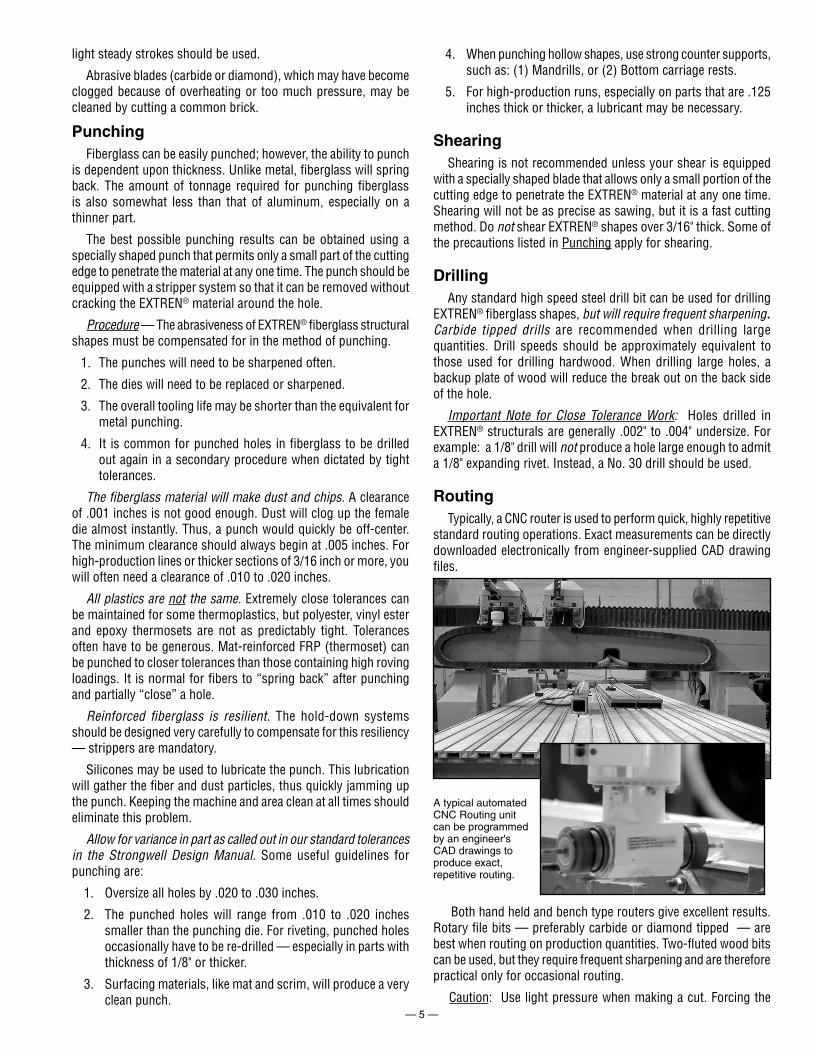
A band saw is ideal for cutting circles, irregular shapes and large shapes.
Cross cutting with radial arm saw (circular) and diamond grit blade.
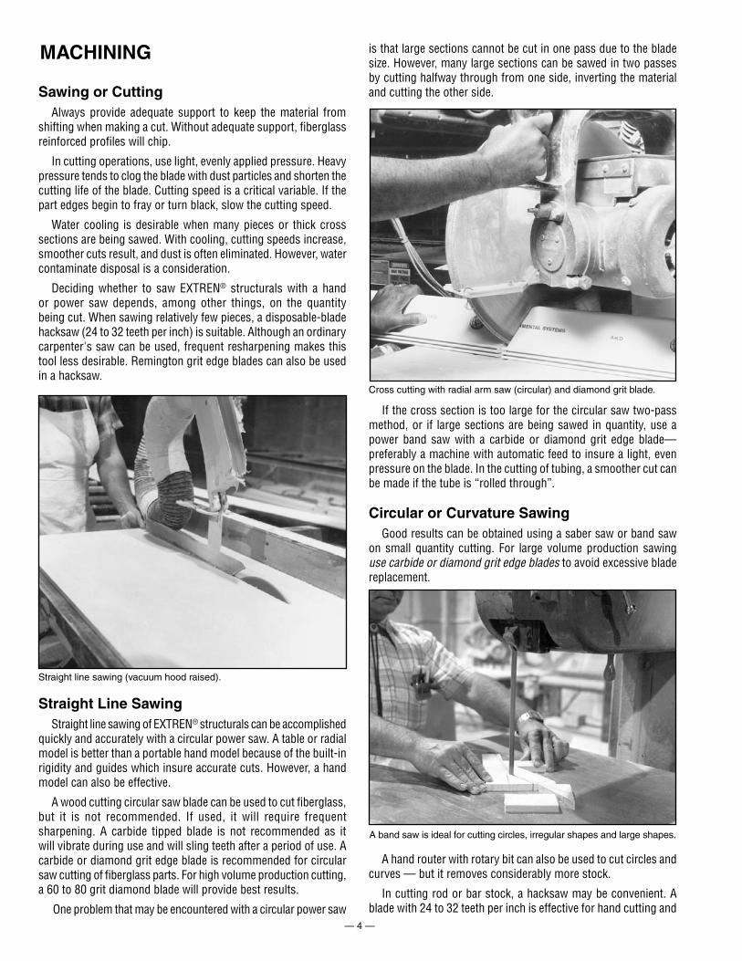
Straight line sawing (vacuum hood raised).
Straight Line SawingStraight line sawing of EXTREN® structurals can be accomplished
quickly and accurately with a circular power saw. A table or radial model is better than a portable hand model because of the built-in rigidity and guides which insure accurate cuts. However, a hand model can also be effective.
A wood cutting circular saw blade can be used to cut fiberglass, but it is not recommended. If used, it will require frequent sharpening. A carbide tipped blade is not recommended as it will vibrate during use and will sling teeth after a period of use. A carbide or diamond grit edge blade is recommended for circular saw cutting of fiberglass parts. For high volume production cutting, a 60 to 80 grit diamond blade will provide best results.
One problem that may be encountered with a circular power saw
is that large sections cannot be cut in one pass due to the blade size. However, many large sections can be sawed in two passes by cutting halfway through from one side, inverting the material and cutting the other side.
If the cross section is too large for the circular saw two-pass method, or if large sections are being sawed in quantity, use a power band saw with a carbide or diamond grit edge blade—preferably a machine with automatic feed to insure a light, even pressure on the blade. In the cutting of tubing, a smoother cut can be made if the tube is “rolled through”.
Circular or Curvature SawingGood results can be obtained using a saber saw or band saw
on small quantity cutting. For large volume production sawing use carbide or diamond grit edge blades to avoid excessive blade replacement.
A hand router with rotary bit can also be used to cut circles and curves — but it removes considerably more stock.
In cutting rod or bar stock, a hacksaw may be convenient. A blade with 24 to 32 teeth per inch is effective for hand cutting and
— 5 —
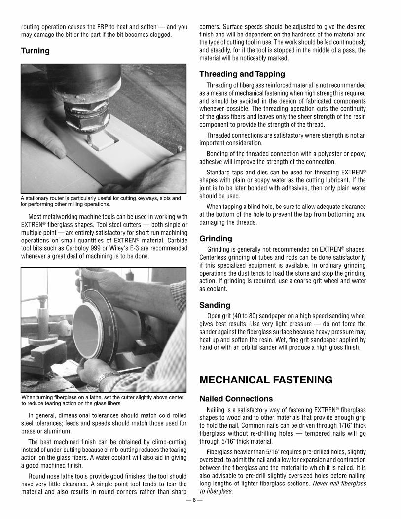
A typical automated CNC Routing unit can be programmed by an engineer's CAD drawings to produce exact, repetitive routing.
light steady strokes should be used.
Abrasive blades (carbide or diamond), which may have become clogged because of overheating or too much pressure, may be cleaned by cutting a common brick.
PunchingFiberglass can be easily punched; however, the ability to punch
is dependent upon thickness. Unlike metal, fiberglass will spring back. The amount of tonnage required for punching fiberglass is also somewhat less than that of aluminum, especially on a thinner part.
The best possible punching results can be obtained using a specially shaped punch that permits only a small part of the cutting edge to penetrate the material at any one time. The punch should be equipped with a stripper system so that it can be removed without cracking the EXTREN® material around the hole.
Procedure — The abrasiveness of EXTREN® fiberglass structural shapes must be compensated for in the method of punching.
1. The punches will need to be sharpened often.
2. The dies will need to be replaced or sharpened.
3. The overall tooling life may be shorter than the equivalent for metal punching.
4. It is common for punched holes in fiberglass to be drilled out again in a secondary procedure when dictated by tight tolerances.
The fiberglass material will make dust and chips. A clearance of .001 inches is not good enough. Dust will clog up the female die almost instantly. Thus, a punch would quickly be off-center. The minimum clearance should always begin at .005 inches. For high-production lines or thicker sections of 3/16 inch or more, you will often need a clearance of .010 to .020 inches.
All plastics are not the same. Extremely close tolerances can be maintained for some thermoplastics, but polyester, vinyl ester and epoxy thermosets are not as predictably tight. Tolerances often have to be generous. Mat-reinforced FRP (thermoset) can be punched to closer tolerances than those containing high roving loadings. It is normal for fibers to “spring back” after punching and partially “close” a hole.
Reinforced fiberglass is resilient. The hold-down systems should be designed very carefully to compensate for this resiliency — strippers are mandatory.
Silicones may be used to lubricate the punch. This lubrication will gather the fiber and dust particles, thus quickly jamming up the punch. Keeping the machine and area clean at all times should eliminate this problem.
Allow for variance in part as called out in our standard tolerances in the Strongwell Design Manual. Some useful guidelines for punching are:
1. Oversize all holes by .020 to .030 inches.
2. The punched holes will range from .010 to .020 inches smaller than the punching die. For riveting, punched holes occasionally have to be re-drilled — especially in parts with thickness of 1/8" or thicker.
3. Surfacing materials, like mat and scrim, will produce a very clean punch.
4. When punching hollow shapes, use strong counter supports, such as: (1) Mandrills, or (2) Bottom carriage rests.
5. For high-production runs, especially on parts that are .125 inches thick or thicker, a lubricant may be necessary.
ShearingShearing is not recommended unless your shear is equipped
with a specially shaped blade that allows only a small portion of the cutting edge to penetrate the EXTREN® material at any one time. Shearing will not be as precise as sawing, but it is a fast cutting method. Do not shear EXTREN® shapes over 3/16" thick. Some of the precautions listed in Punching apply for shearing.
DrillingAny standard high speed steel drill bit can be used for drilling
EXTREN® fiberglass shapes, but will require frequent sharpening. Carbide tipped drills are recommended when drilling large quantities. Drill speeds should be approximately equivalent to those used for drilling hardwood. When drilling large holes, a backup plate of wood will reduce the break out on the back side of the hole.
Important Note for Close Tolerance Work: Holes drilled in EXTREN® structurals are generally .002" to .004" undersize. For example: a 1/8" drill will not produce a hole large enough to admit a 1/8" expanding rivet. Instead, a No. 30 drill should be used.
RoutingTypically, a CNC router is used to perform quick, highly repetitive
standard routing operations. Exact measurements can be directly downloaded electronically from engineer-supplied CAD drawing files.
Both hand held and bench type routers give excellent results. Rotary file bits — preferably carbide or diamond tipped — are best when routing on production quantities. Two-fluted wood bits can be used, but they require frequent sharpening and are therefore practical only for occasional routing.
Caution: Use light pressure when making a cut. Forcing the
— 6 —
A stationary router is particularly useful for cutting keyways, slots and for performing other milling operations.
When turning fiberglass on a lathe, set the cutter slightly above center to reduce tearing action on the glass fibers.
MECHANICAL FASTENING
Nailed ConnectionsNailing is a satisfactory way of fastening EXTREN® fiberglass
shapes to wood and to other materials that provide enough grip to hold the nail. Common nails can be driven through 1/16" thick fiberglass without re-drilling holes — tempered nails will go through 5/16" thick material.
Fiberglass heavier than 5/16" requires pre-drilled holes, slightly oversized, to admit the nail and allow for expansion and contraction between the fiberglass and the material to which it is nailed. It is also advisable to pre-drill slightly oversized holes before nailing long lengths of lighter fiberglass sections. Never nail fiberglass to fiberglass.
routing operation causes the FRP to heat and soften — and you may damage the bit or the part if the bit becomes clogged.
Turning
Most metalworking machine tools can be used in working with EXTREN® fiberglass shapes. Tool steel cutters — both single or multiple point — are entirely satisfactory for short run machining operations on small quantities of EXTREN® material. Carbide tool bits such as Carboloy 999 or Wiley's E-3 are recommended whenever a great deal of machining is to be done.
In general, dimensional tolerances should match cold rolled steel tolerances; feeds and speeds should match those used for brass or aluminum.
The best machined finish can be obtained by climb-cutting instead of under-cutting because climb-cutting reduces the tearing action on the glass fibers. A water coolant will also aid in giving a good machined finish.
Round nose lathe tools provide good finishes; the tool should have very little clearance. A single point tool tends to tear the material and also results in round corners rather than sharp
corners. Surface speeds should be adjusted to give the desired finish and will be dependent on the hardness of the material and the type of cutting tool in use. The work should be fed continuously and steadily, for if the tool is stopped in the middle of a pass, the material will be noticeably marked.
Threading and TappingThreading of fiberglass reinforced material is not recommended
as a means of mechanical fastening when high strength is required and should be avoided in the design of fabricated components whenever possible. The threading operation cuts the continuity of the glass fibers and leaves only the sheer strength of the resin component to provide the strength of the thread.
Threaded connections are satisfactory where strength is not an important consideration.
Bonding of the threaded connection with a polyester or epoxy adhesive will improve the strength of the connection.
Standard taps and dies can be used for threading EXTREN® shapes with plain or soapy water as the cutting lubricant. If the joint is to be later bonded with adhesives, then only plain water should be used.
When tapping a blind hole, be sure to allow adequate clearance at the bottom of the hole to prevent the tap from bottoming and damaging the threads.
GrindingGrinding is generally not recommended on EXTREN® shapes.
Centerless grinding of tubes and rods can be done satisfactorily if this specialized equipment is available. In ordinary grinding operations the dust tends to load the stone and stop the grinding action. If grinding is required, use a coarse grit wheel and water as coolant.
SandingOpen grit (40 to 80) sandpaper on a high speed sanding wheel
gives best results. Use very light pressure — do not force the sander against the fiberglass surface because heavy pressure may heat up and soften the resin. Wet, fine grit sandpaper applied by hand or with an orbital sander will produce a high gloss finish.
— 7 —
Screwed ConnectionsSelf-tapping screws have been used successfully in many
applications involving mechanical connections when high strength fasteners are not required. A better use of self-tapping screws is in combination with adhesives. In this application, the screws can serve to hold the adhesive bonded surface of the two parts together while the adhesive cures in addition to contributing limited mechanical strength to the connection. Appropriately sized pilot holes should be provided in the EXTREN® shape for the screws. In corrosive environments, stainless steel or monel screws should be used — unless a suitable coating of polyester or epoxy can be applied to the exposed screw heads to prevent corrosive attack of the fasteners.
Lag screws are not recommended because they do not bite well in the fiberglass.
Bolted ConnectionsA very satisfactory connection can be made with EXTREN®
fiberglass components by using standard bolts, nuts and washers. Since fiberglass materials can fail under high localized stress conditions, such as those encountered around a bolt, the tighter the bolt is in the hole, the more effective it will be. Always use flat washers on both sides of bolt connections.
The strongest joint between pieces of EXTREN® shapes is obtained by using a combination of properly fitted bolts with adhesives applied to the properly prepared mating surfaces.
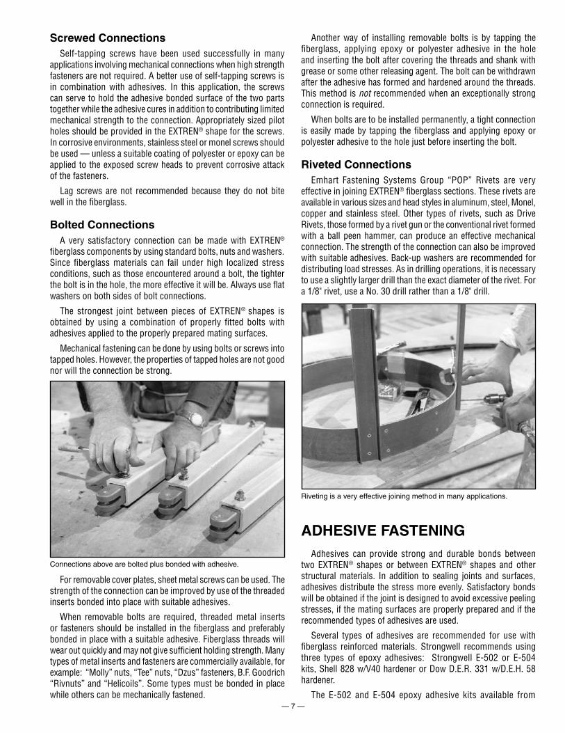
Mechanical fastening can be done by using bolts or screws into tapped holes. However, the properties of tapped holes are not good nor will the connection be strong.
Connections above are bolted plus bonded with adhesive.
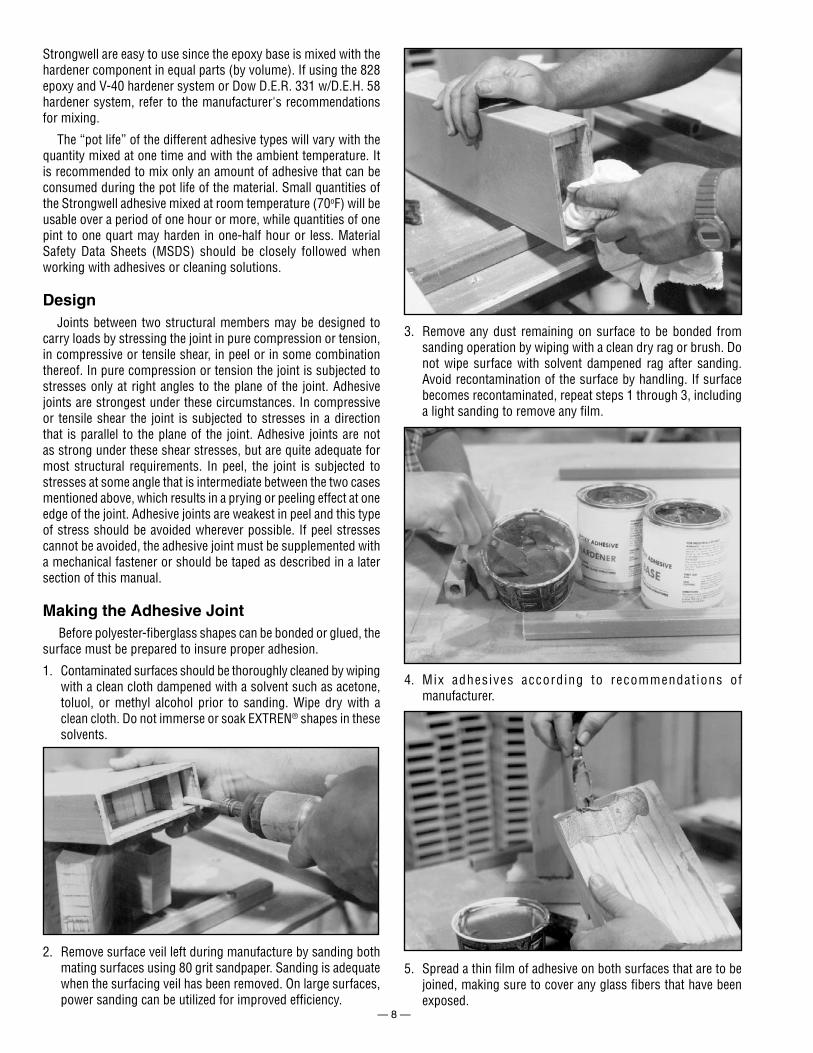
Riveting is a very effective joining method in many applications.
Another way of installing removable bolts is by tapping the fiberglass, applying epoxy or polyester adhesive in the hole and inserting the bolt after covering the threads and shank with grease or some other releasing agent. The bolt can be withdrawn after the adhesive has formed and hardened around the threads. This method is not recommended when an exceptionally strong connection is required.
When bolts are to be installed permanently, a tight connection is easily made by tapping the fiberglass and applying epoxy or polyester adhesive to the hole just before inserting the bolt.
Riveted ConnectionsEmhart Fastening Systems Group “POP” Rivets are very
effective in joining EXTREN® fiberglass sections. These rivets are available in various sizes and head styles in aluminum, steel, Monel, copper and stainless steel. Other types of rivets, such as Drive Rivets, those formed by a rivet gun or the conventional rivet formed with a ball peen hammer, can produce an effective mechanical connection. The strength of the connection can also be improved with suitable adhesives. Back-up washers are recommended for distributing load stresses. As in drilling operations, it is necessary to use a slightly larger drill than the exact diameter of the rivet. For a 1/8" rivet, use a No. 30 drill rather than a 1/8" drill.
ADHESIVE FASTENINGAdhesives can provide strong and durable bonds between
two EXTREN® shapes or between EXTREN® shapes and other structural materials. In addition to sealing joints and surfaces, adhesives distribute the stress more evenly. Satisfactory bonds will be obtained if the joint is designed to avoid excessive peeling stresses, if the mating surfaces are properly prepared and if the recommended types of adhesives are used.
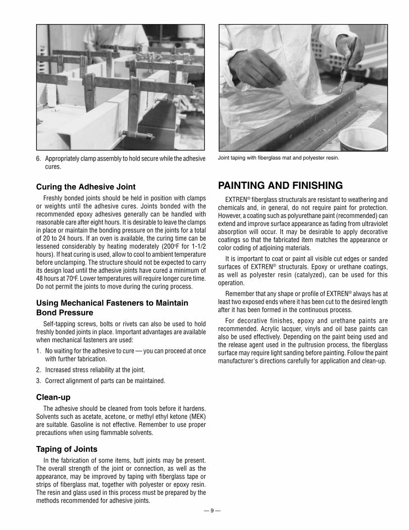
Several types of adhesives are recommended for use with fiberglass reinforced materials. Strongwell recommends using three types of epoxy adhesives: Strongwell E-502 or E-504 kits, Shell 828 w/V40 hardener or Dow D.E.R. 331 w/D.E.H. 58 hardener.
The E-502 and E-504 epoxy adhesive kits available from
For removable cover plates, sheet metal screws can be used. The strength of the connection can be improved by use of the threaded inserts bonded into place with suitable adhesives.
When removable bolts are required, threaded metal inserts or fasteners should be installed in the fiberglass and preferably bonded in place with a suitable adhesive. Fiberglass threads will wear out quickly and may not give sufficient holding strength. Many types of metal inserts and fasteners are commercially available, for example: “Molly” nuts, “Tee” nuts, “Dzus” fasteners, B.F. Goodrich “Rivnuts” and “Helicoils”. Some types must be bonded in place while others can be mechanically fastened.
— 8 —
3. Remove any dust remaining on surface to be bonded from sanding operation by wiping with a clean dry rag or brush. Do not wipe surface with solvent dampened rag after sanding. Avoid recontamination of the surface by handling. If surface becomes recontaminated, repeat steps 1 through 3, including a light sanding to remove any film.
4. Mix adhesives according to recommendat ions of manufacturer.
Strongwell are easy to use since the epoxy base is mixed with the hardener component in equal parts (by volume). If using the 828 epoxy and V-40 hardener system or Dow D.E.R. 331 w/D.E.H. 58 hardener system, refer to the manufacturer's recommendations for mixing.
The “pot life” of the different adhesive types will vary with the quantity mixed at one time and with the ambient temperature. It is recommended to mix only an amount of adhesive that can be consumed during the pot life of the material. Small quantities of the Strongwell adhesive mixed at room temperature (70oF) will be usable over a period of one hour or more, while quantities of one pint to one quart may harden in one-half hour or less. Material Safety Data Sheets (MSDS) should be closely followed when working with adhesives or cleaning solutions.
DesignJoints between two structural members may be designed to
carry loads by stressing the joint in pure compression or tension, in compressive or tensile shear, in peel or in some combination thereof. In pure compression or tension the joint is subjected to stresses only at right angles to the plane of the joint. Adhesive joints are strongest under these circumstances. In compressive or tensile shear the joint is subjected to stresses in a direction that is parallel to the plane of the joint. Adhesive joints are not as strong under these shear stresses, but are quite adequate for most structural requirements. In peel, the joint is subjected to stresses at some angle that is intermediate between the two cases mentioned above, which results in a prying or peeling effect at one edge of the joint. Adhesive joints are weakest in peel and this type of stress should be avoided wherever possible. If peel stresses cannot be avoided, the adhesive joint must be supplemented with a mechanical fastener or should be taped as described in a later section of this manual.
Making the Adhesive JointBefore polyester-fiberglass shapes can be bonded or glued, the
surface must be prepared to insure proper adhesion.
1. Contaminated surfaces should be thoroughly cleaned by wiping with a clean cloth dampened with a solvent such as acetone, toluol, or methyl alcohol prior to sanding. Wipe dry with a clean cloth. Do not immerse or soak EXTREN® shapes in these solvents.
2. Remove surface veil left during manufacture by sanding both mating surfaces using 80 grit sandpaper. Sanding is adequate when the surfacing veil has been removed. On large surfaces, power sanding can be utilized for improved efficiency.
5. Spread a thin film of adhesive on both surfaces that are to be joined, making sure to cover any glass fibers that have been exposed.
— 9 —
Joint taping with fiberglass mat and polyester resin.6. Appropriately clamp assembly to hold secure while the adhesive cures.
Curing the Adhesive JointFreshly bonded joints should be held in position with clamps
or weights until the adhesive cures. Joints bonded with the recommended epoxy adhesives generally can be handled with reasonable care after eight hours. It is desirable to leave the clamps in place or maintain the bonding pressure on the joints for a total of 20 to 24 hours. If an oven is available, the curing time can be lessened considerably by heating moderately (200oF for 1-1/2 hours). If heat curing is used, allow to cool to ambient temperature before unclamping. The structure should not be expected to carry its design load until the adhesive joints have cured a minimum of 48 hours at 70oF. Lower temperatures will require longer cure time. Do not permit the joints to move during the curing process.
Using Mechanical Fasteners to Maintain Bond Pressure
Self-tapping screws, bolts or rivets can also be used to hold freshly bonded joints in place. Important advantages are available when mechanical fasteners are used:
1. No waiting for the adhesive to cure — you can proceed at once with further fabrication.
2. Increased stress reliability at the joint.
3. Correct alignment of parts can be maintained.
Clean-upThe adhesive should be cleaned from tools before it hardens.
Solvents such as acetate, acetone, or methyl ethyl ketone (MEK) are suitable. Gasoline is not effective. Remember to use proper precautions when using flammable solvents.
Taping of JointsIn the fabrication of some items, butt joints may be present.
The overall strength of the joint or connection, as well as the appearance, may be improved by taping with fiberglass tape or strips of fiberglass mat, together with polyester or epoxy resin. The resin and glass used in this process must be prepared by the methods recommended for adhesive joints.
PAINTING AND FINISHINGEXTREN® fiberglass structurals are resistant to weathering and
chemicals and, in general, do not require paint for protection. However, a coating such as polyurethane paint (recommended) can extend and improve surface appearance as fading from ultraviolet absorption will occur. It may be desirable to apply decorative coatings so that the fabricated item matches the appearance or color coding of adjoining materials.
It is important to coat or paint all visible cut edges or sanded surfaces of EXTREN® structurals. Epoxy or urethane coatings, as well as polyester resin (catalyzed), can be used for this operation.
Remember that any shape or profile of EXTREN® always has at least two exposed ends where it has been cut to the desired length after it has been formed in the continuous process.
For decorative finishes, epoxy and urethane paints are recommended. Acrylic lacquer, vinyls and oil base paints can also be used effectively. Depending on the paint being used and the release agent used in the pultrusion process, the fiberglass surface may require light sanding before painting. Follow the paint manufacturer's directions carefully for application and clean-up.
— 10 —
REPAIR
QUICK REPAIR GUIDE
Problem Procedure Page
Maintenance Cleaning 11Cuts and scratches Resin Sealing 11Cracks Splicing 12Chipped flange Resin Filling 14Burns Burns 15Small cracks Glass Lay-Up 15Holes mislocated Hole Filling 16
FABRICATION & REPAIR MANUAL
— 11 —
CLEANINGPrior to any repairs, it is necessary to remove foreign material
which may contribute to poor adhesion in the repair and/or electrical problems. Routine cleaning is recommended as a preventative maintenance measure. Two methods have been employed in cleaning EXTREN®; one method involves a solvent wipe technique and the other method utilizes steam cleaning.
Solvent WipingThis method is popular because it does not rely on the
accessibility of a steam line. For many EXTREN® shapes already in service, this is the only practical technique. In this procedure, the EXTREN® shape should be wiped using a non-abrasive cloth and a solvent such as acetone (highly flammable). The cloth may require repeated soaking in these solvents as they evaporate quickly (do not use gasoline). Do not wipe surfaces to be adhesively bonded with a solvent dampened cloth (see pg. 8 “Making the Adhesive Joint”).
Note: Do not immerse EXTREN® in solvents as prolonged soaking may cause damage.
Caution: Most solvents are flammable and the vapors can be harmful; do not apply by spraying.
Abrasive cloths may ultimately be required for complete cleaning. If these are used, some surface repair may be required prior to returning the part to service.
Steam CleaningThe following procedure should be followed if the part is to be
cleaned by steam:
1. The steam heat temperature should not exceed 250oF; the pressure should be below 85 psi.
2. For steam cleaning, elevate one end of the EXTREN® shape whenever possible; this permits drainage for the dirt and condensed water. Do not turn the steam jet directly onto any hose assembly (as in booms) for an extended period; this may cause hose damage.
3. Do not apply the steam jet directly to any adhesive joints as this may loosen the joints resulting in erroneous electrical readings or other problems.
4. Permit the EXTREN® shape to dry for 24 hours after steam cleaning as the areas to be repaired must be dry.
5. Use the Solvent Wiping procedure for difficult substances such as road tar.
InspectionPart of the cleaning procedure must be a thorough inspection
of the EXTREN® shape. Ruptures to the surface can be caused by bolts, tools, or other items striking the part. Minor impacts normally have a minimal effect on the electrical and/or mechanical properties of the structural shape, but may cause cosmetic problems.
If any question on the performance of the EXTREN® exist, contact Strongwell's Customer Service Department, (276) 645-8000.
REPAIR PROCEDURE — RESIN SEALING
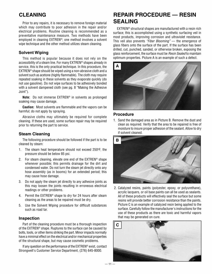
EXTREN® structural shapes are manufactured with a resin rich surface; this is accomplished using a synthetic surfacing veil in most products, improving corrosion and ultraviolet resistance. This veil also prevents “Fiber Blooming” — the emergence of glass fibers onto the surface of the part. If the surface has been drilled, cut, punched, sanded, or otherwise broken, exposing the glass reinforcement, the surface must be Resin Sealed to maintain optimum properties. Picture A is an example of such a defect.
Procedure1. Sand the damaged area as in Picture B. Remove the dust and
clean as required. Verify that the area to be repaired is free of moisture to insure proper adhesion of the sealant. Allow to dry if solvent cleaned.
A
B
2. Catalyzed resins, paints (polyester, epoxy, or polyurethane), acrylic lacquers, or oil base paints can all be used as sealants. All of these products will effectively seal the surface but some resins will provide better corrosion resistance than the paints. Picture C is an example of catalyzed resin being applied to the surface. Carefully follow the manufacturer's instructions for the use of these products as there are toxic and harmful vapors that may be generated on cure.
C
— 12 —
REPAIR PROCEDURE — SPLICING
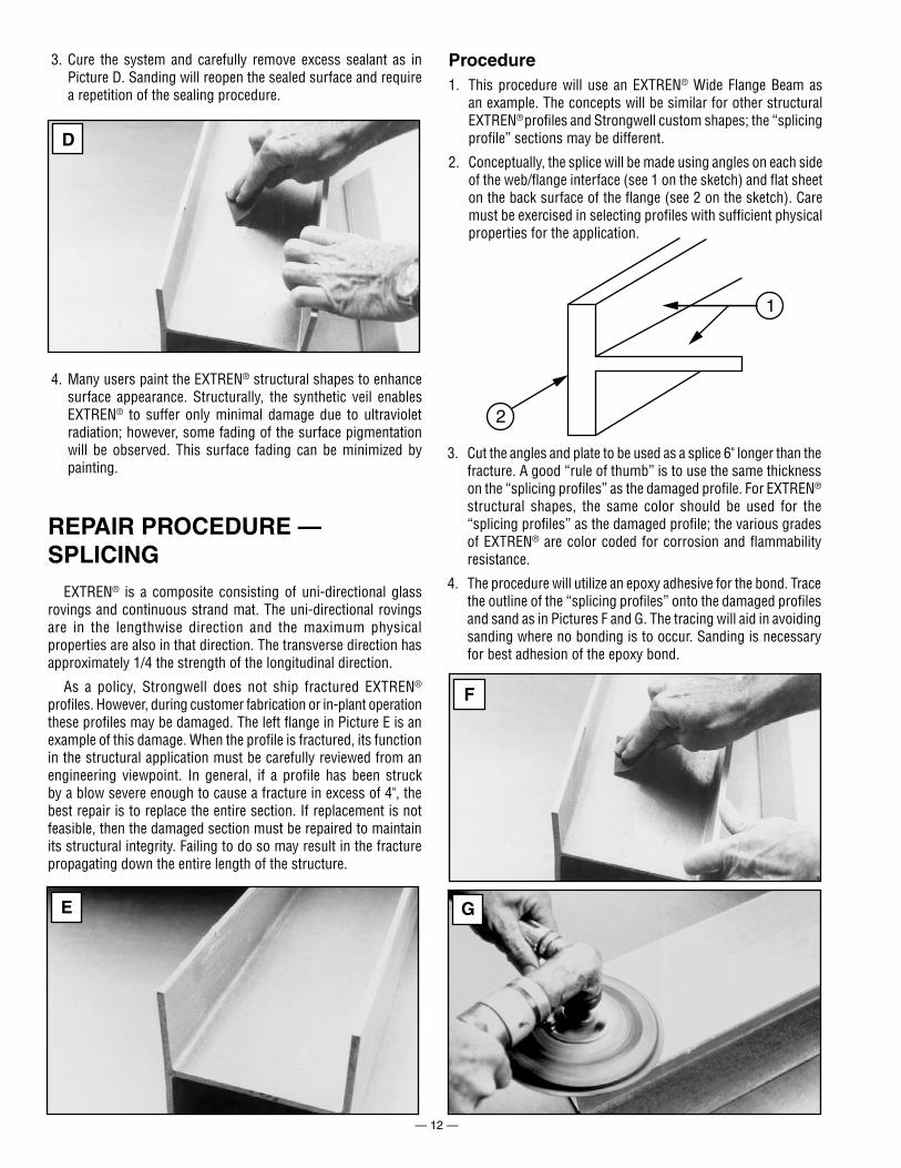
EXTREN® is a composite consisting of uni-directional glass rovings and continuous strand mat. The uni-directional rovings are in the lengthwise direction and the maximum physical properties are also in that direction. The transverse direction has approximately 1/4 the strength of the longitudinal direction.
As a policy, Strongwell does not ship fractured EXTREN® profiles. However, during customer fabrication or in-plant operation these profiles may be damaged. The left flange in Picture E is an example of this damage. When the profile is fractured, its function in the structural application must be carefully reviewed from an engineering viewpoint. In general, if a profile has been struck by a blow severe enough to cause a fracture in excess of 4", the best repair is to replace the entire section. If replacement is not feasible, then the damaged section must be repaired to maintain its structural integrity. Failing to do so may result in the fracture propagating down the entire length of the structure.
Procedure1. This procedure will use an EXTREN® Wide Flange Beam as
an example. The concepts will be similar for other structural EXTREN® profiles and Strongwell custom shapes; the “splicing profile” sections may be different.
2. Conceptually, the splice will be made using angles on each side of the web/flange interface (see 1 on the sketch) and flat sheet on the back surface of the flange (see 2 on the sketch). Care must be exercised in selecting profiles with sufficient physical properties for the application.
3. Cure the system and carefully remove excess sealant as in Picture D. Sanding will reopen the sealed surface and require a repetition of the sealing procedure.
4. Many users paint the EXTREN® structural shapes to enhance surface appearance. Structurally, the synthetic veil enables EXTREN® to suffer only minimal damage due to ultraviolet radiation; however, some fading of the surface pigmentation will be observed. This surface fading can be minimized by painting.
3. Cut the angles and plate to be used as a splice 6" longer than the fracture. A good “rule of thumb” is to use the same thickness on the “splicing profiles” as the damaged profile. For EXTREN® structural shapes, the same color should be used for the “splicing profiles” as the damaged profile; the various grades of EXTREN® are color coded for corrosion and flammability resistance.
4. The procedure will utilize an epoxy adhesive for the bond. Trace the outline of the “splicing profiles” onto the damaged profiles and sand as in Pictures F and G. The tracing will aid in avoiding sanding where no bonding is to occur. Sanding is necessary for best adhesion of the epoxy bond.
2
1
D
E
F
G
— 13 —
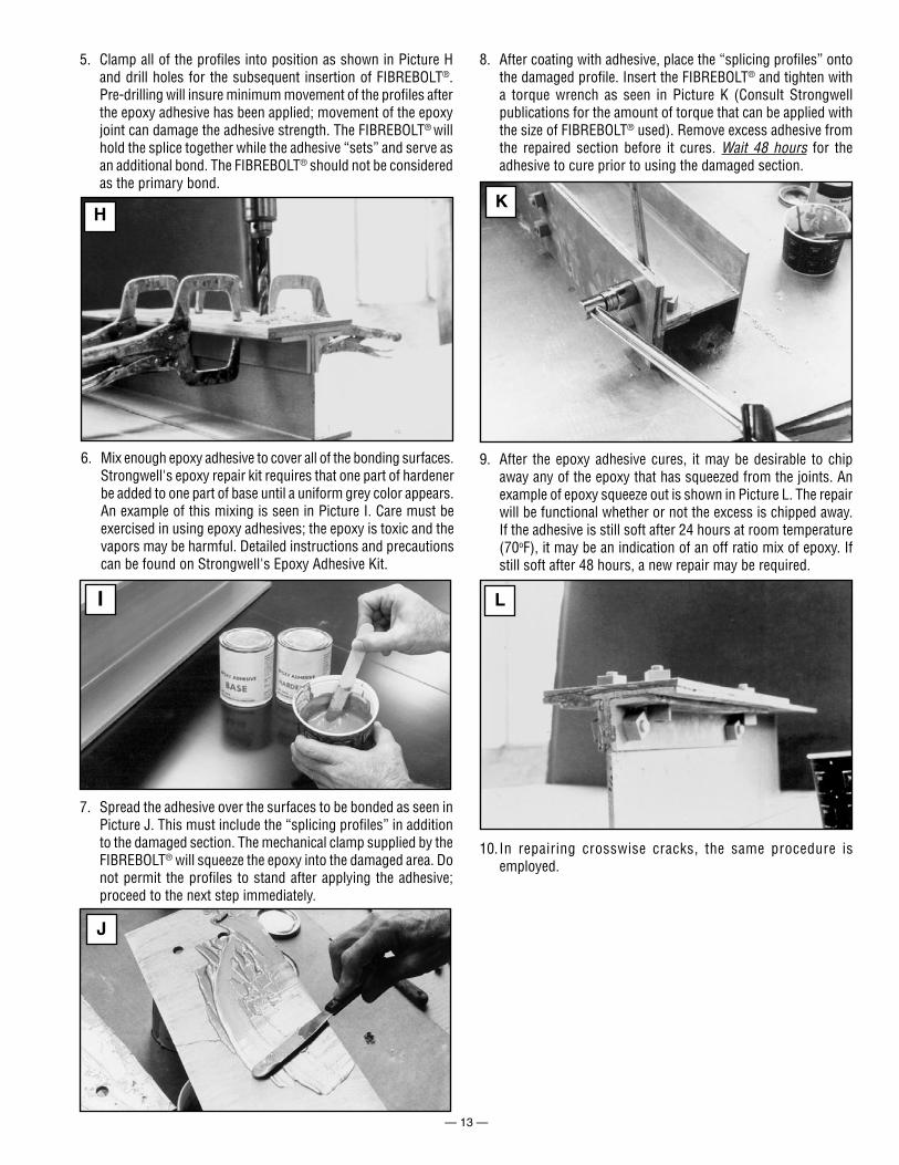
6. Mix enough epoxy adhesive to cover all of the bonding surfaces. Strongwell's epoxy repair kit requires that one part of hardener be added to one part of base until a uniform grey color appears. An example of this mixing is seen in Picture I. Care must be exercised in using epoxy adhesives; the epoxy is toxic and the vapors may be harmful. Detailed instructions and precautions can be found on Strongwell's Epoxy Adhesive Kit.
7. Spread the adhesive over the surfaces to be bonded as seen in Picture J. This must include the “splicing profiles” in addition to the damaged section. The mechanical clamp supplied by the FIBREBOLT® will squeeze the epoxy into the damaged area. Do not permit the profiles to stand after applying the adhesive; proceed to the next step immediately.
8. After coating with adhesive, place the “splicing profiles” onto the damaged profile. Insert the FIBREBOLT® and tighten with a torque wrench as seen in Picture K (Consult Strongwell publications for the amount of torque that can be applied with the size of FIBREBOLT® used). Remove excess adhesive from the repaired section before it cures. Wait 48 hours for the adhesive to cure prior to using the damaged section.
9. After the epoxy adhesive cures, it may be desirable to chip away any of the epoxy that has squeezed from the joints. An example of epoxy squeeze out is shown in Picture L. The repair will be functional whether or not the excess is chipped away. If the adhesive is still soft after 24 hours at room temperature (70oF), it may be an indication of an off ratio mix of epoxy. If still soft after 48 hours, a new repair may be required.
5. Clamp all of the profiles into position as shown in Picture H and drill holes for the subsequent insertion of FIBREBOLT®. Pre-drilling will insure minimum movement of the profiles after the epoxy adhesive has been applied; movement of the epoxy joint can damage the adhesive strength. The FIBREBOLT® will hold the splice together while the adhesive “sets” and serve as an additional bond. The FIBREBOLT® should not be considered as the primary bond.
H
I
J
K
L
10. In repairing crosswise cracks, the same procedure is employed.
— 14 —
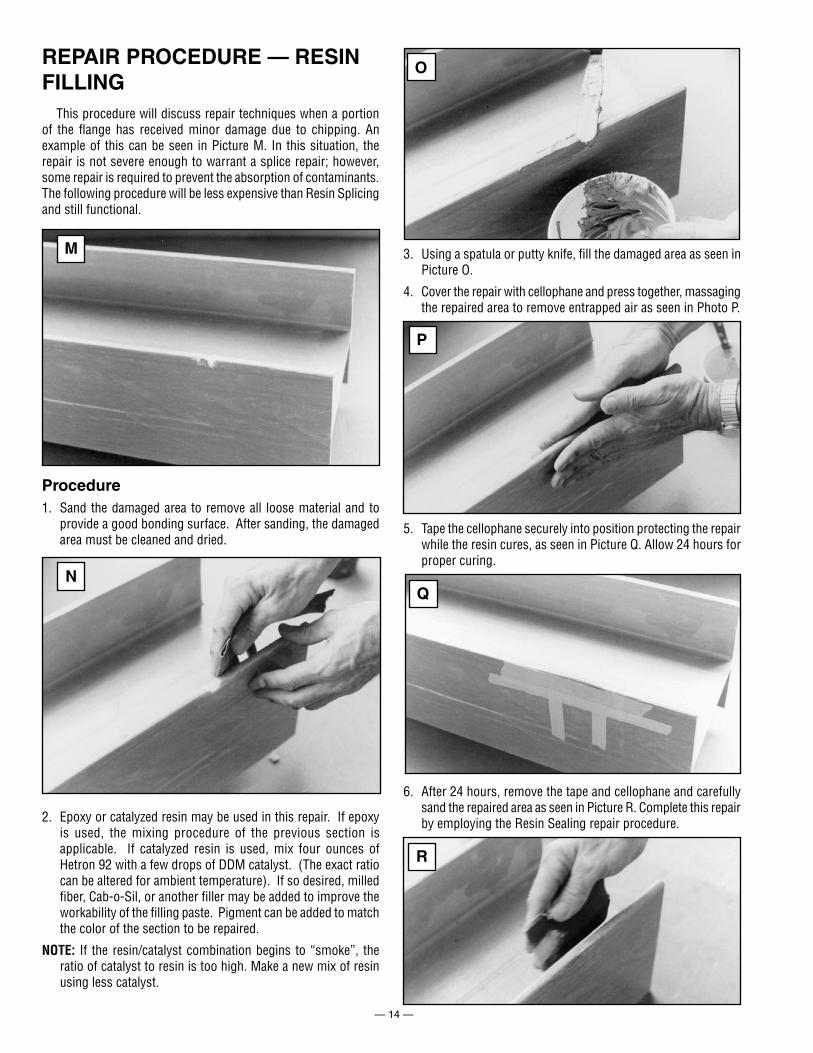
3. Using a spatula or putty knife, fill the damaged area as seen in Picture O.
4. Cover the repair with cellophane and press together, massaging the repaired area to remove entrapped air as seen in Photo P.
5. Tape the cellophane securely into position protecting the repair while the resin cures, as seen in Picture Q. Allow 24 hours for proper curing.
6. After 24 hours, remove the tape and cellophane and carefully sand the repaired area as seen in Picture R. Complete this repair by employing the Resin Sealing repair procedure.
This procedure will discuss repair techniques when a portion of the flange has received minor damage due to chipping. An example of this can be seen in Picture M. In this situation, the repair is not severe enough to warrant a splice repair; however, some repair is required to prevent the absorption of contaminants. The following procedure will be less expensive than Resin Splicing and still functional.
REPAIR PROCEDURE — RESIN FILLING
Procedure1. Sand the damaged area to remove all loose material and to
provide a good bonding surface. After sanding, the damaged area must be cleaned and dried.
2. Epoxy or catalyzed resin may be used in this repair. If epoxy is used, the mixing procedure of the previous section is applicable. If catalyzed resin is used, mix four ounces of Hetron 92 with a few drops of DDM catalyst. (The exact ratio can be altered for ambient temperature). If so desired, milled fiber, Cab-o-Sil, or another filler may be added to improve the workability of the filling paste. Pigment can be added to match the color of the section to be repaired.
NOTE: If the resin/catalyst combination begins to “smoke”, the ratio of catalyst to resin is too high. Make a new mix of resin using less catalyst.
M
N
O
P
Q
R
— 15 —
REPAIR PROCEDURE — BURNS
Occasionally, EXTREN® shapes may be exposed to sparks or flames from cutting and/or welding. The resultant damage may range from cosmetic to structural. The extent of the damage can only be ascertained after removal of the charred area using sanding techniques. Portions of the EXTREN®, which have not been discolored, can be assumed to have received insufficient heat to cause property problems.
After the char has been removed, the size of the imperfection will dictate the nature of the repair. An engineering decision must be made on which of the procedures presented in this manual is to be employed. At a minimum, the surface should be resealed; if the char area is large and deep, the part should be replaced.
As with all charring, any smoke released may be hazardous if inhaled. The area around the charred part should be ventilated before affecting a repair.
This technique applies when the crack is small and the structural integrity is not threatened. This technique is similar to some procedures used in automotive body repair.
Procedure1. Sand the damaged area. Taper both sides of the damaged area
approximately 2" to 3" above and below the crack and 2" to 3" on either side of the crack.
2. Remove all dust and clean the area to be repaired.
3. Cut a piece of glass mat to cover within 1/2" at the edges of the sanded area.
4. Cut a piece of 10 mil veil to cover all of the sanded area (multiple pieces may be used if overlapped at joints).
5. Weigh the glass veil and mat. Weigh 4 times that weight in resin and add 1% - 5% of DDM catalyst (start with 1%). Stir thoroughly. The pot life of this mixture is dependent upon the percent of catalyst and the ambient temperature and must be determined on sight. Do not attempt to use catalyzed resin after it begins to gel (becoming like jello).
6. Paint the sanded area with this resin/catalyst mixture.
7. Apply glass material and thoroughly wet with the resin/catalyst mixture.
8. Add layers of glass and resin to obtain the desired repair thickness and remove air from each layer.
9. Cover with cellophane until the repair is cured.
10. Sand to a smooth finish and coat with resin mixture for corrosion protection.
REPAIR PROCEDURE — GLASS LAY-UP
SUGGESTIONS FOR HOLE FILLING
A relatively common problem in structural fabrication is hole mislocation. This can occur because of shop error, a drawing error, or a design change after the hole or holes have already been drilled. How the hole is repaired depends on a number of factors including how the load on the structure will be applied, how important appearance is, and the proximity of other holes.
What follows are two suggested techniques for hole filling.
FIBREBOLT® Procedure1. Drill the mislocated hole to the nearest tap size.
2. Tap the hole to the smallest FIBREBOLT® size you have on hand.
3. Apply epoxy adhesive to both the FIBREBOLT® threads and the hole edges.
4. Screw the FIBREBOLT® into the hole.
5. Cut the FIBREBOLT® as close to the material being penetrated as possible.
6. Grind flush.
7. Reseal area with resin after epoxy has cured.
This procedure works well when no other holes are very near the mislocated hole and the new hole location does not intersect the old hole. If another hole is very close or the right location would intersect the mislocated hole, the counterbore procedure (that follows) is suggested.
Counterbore Procedure1. Using a flattened bit, approximately twice the diameter of the
mislocated hole, counterbore halfway through the material with the center of the counterbore being the center of the mislocated hole.
2. Using a hole saw, cut a plug for the counterbore from an EXTREN® plate which is half the thickness of the material being repaired. Sand the plug and epoxy it in place. Let the adhesive cure.
3. After the adhesive has cured, and again using a hole saw, cut a similar plug that is the same size as the original hole. Working from the opposite side of the material being repaired as before, epoxy this plug into place. Let it cure.
4. Sand and reseal with resin as necessary.
Neither of these repair techniques will restore original EXTREN® properties.
NOTE: For more information on fabrication of fiberglass structural shapes, see Section 19 of the Strongwell Design Manual. This publication is available on Strongwell's website at www.strongwell.com.
BRISTOL DIVISION*400 Commonwealth Ave., P. O. Box 580, Bristol, VA 24203-0580
(276) 645-8000 FAX (276) 645-8132*EXTREN® manufacturing location
CHATFIELD DIVISION1610 Highway 52 South, Chatfield, MN 55923-9799
(507) 867-3479 FAX (507) 867-4031
www.strongwell.com
®
ISO-9001:2000 Certified Manufacturing Plants
TYPICAL CONNECTIONS
INT5M0908© 2008 Strongwell