Embed Size (px)
Citation preview
Fabrication of Surface Metal Matrix
Composites Using Friction Stir Processing
by
Saman Sahraeinejad
A thesis
presented to the University of Waterloo
in fulfillment of the
thesis requirement for the degree of
Master of Applied Science
in
Mechanical Engineering
Waterloo, Ontario, Canada, Year
©Saman Sahraeinejad 2014

ii
AUTHOR'S DECLARATION
I hereby declare that I am the sole author of this thesis. This is a true copy of the thesis, including any
required final revisions, as accepted by my examiners.
I understand that my thesis may be made electronically available to the public.
iii
Abstract
Friction stir processing has been employed to produce metal matrix composites by
incorporating reinforcement particles in an Al 5059 matrix. Various particles with sizes from
130 nm to 4.3 µm, and different process parameters, were examined to obtain a uniform
distribution of particles within the processed region. Mechanical properties (i.e. tensile and
microhardness) of the Al 5059 matrix metal matrix composites reinforced with Al2O3, SiC,
and B4C were tested and compared. Tensile tests demonstrated increases in yield strength by
20, 32, and 38 percent compared to the matrix alloy for composites containing Al2O3, SiC,
and B4C, respectively. The average microhardness value within the stir zone increased from
85 HV in the base material to a maximum of 170 HV in the B4C-reinforced composite.
Particle refinement during friction stir processing was more pronounced with micron-sized
particles, and virtually insignificant for nano-sized particles. Nano-scale particles seem to be
more efficient in increasing the hardness when a similar fraction is used compared to micro-
sized particles.

iv
Acknowledgements
I would like to express the sincere appreciation to my supervisor professor Adrian Gerlich, who has
shown the attitude and the substance of a genius: he continually and persuasively conveyed a spirit of
adventure in regard to research and scholarship, and an excitement in regard to teaching. Without his
supervision and constant help writing of this thesis would not have been possible.

v
Dedication
I dedicate this thesis to my wife, Minoo, for her love, support, and encouragement each step of the
way.
vi
Table of Contents AUTHOR'S DECLARATION ............................................................................................................... ii
Abstract ................................................................................................................................................. iii
Acknowledgements ............................................................................................................................... iv
Dedication .............................................................................................................................................. v
Table of Contents .................................................................................................................................. vi
List of Figures ...................................................................................................................................... vii
List of Tables ....................................................................................................................................... vii
Chapter 1 Introduction ........................................................................................................................... 1
Chapter 2 Literature review ................................................................................................................... 4
2.1 Composite Materials .................................................................................................................... 4
2.1.1 Particle reinforced composites .............................................................................................. 5
2.1.2 Metal Matrix Composites (MMCs) ....................................................................................... 7
2.1.3 Mechanism of reinforcement in MMCs .............................................................................. 13
2.2 Friction Stir Processing, FSP ..................................................................................................... 15
2.2.1 Microstructure evolution during FSP .................................................................................. 17
2.2.2 Mechanical Properties enhancement during FSP ................................................................ 18
2.2.3 Friction stir processing tool design ..................................................................................... 21
2.3 Fabrication MMCs using FSP .................................................................................................... 28
Chapter 3 Experimental ....................................................................................................................... 32
Chapter 4 Results and Discussion ........................................................................................................ 39
4.1 Particle distribution .................................................................................................................... 39
4.2 Mechanical testing and fractography ......................................................................................... 42
Chapter 5 Conclusions ......................................................................................................................... 52
Bibliography ........................................................................................................................................ 53
vii
List of Figures Figure 1 Schematic classification for various composites ...................................................................... 4
Figure 2: Modulus of elasticity versus volume percent tungsten for a composite of tungsten particles
dispersed within a copper matrix. Upper and lower bounds are according to Eq.1 and Eq. 2.
[49] .......................................................................................................................................... 6
Figure 3: Micrograph of a WC–Co cemented carbide. Light areas are the cobalt matrix; dark regions,
the particles of tungsten carbide[48]. ...................................................................................... 7
Figure 4: Schematic illustration of three types of metal matrix composite materials[53] ...................... 8
Figure 5: Casting process for particulate or short fiber MMCs .............................................................. 9
Figure 6: Reactive liquid metal infiltration process [55] ........................................................................ 9
Figure 7: Squeeze casting or pressure infiltration process[57] ............................................................. 10
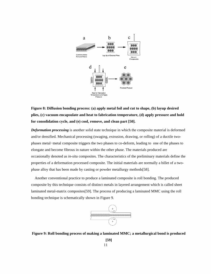
Figure 8: Diffusion bonding process: (a) apply metal foil and cut to shape, (b) layup desired plies, (c)
vacuum encapsulate and heat to fabrication temperature, (d) apply pressure and hold for
consolidation cycle, and (e) cool, remove, and clean part [50]. ............................................ 11
Figure 9: Roll bonding process of making a laminated MMC; a metallurgical bond is produced [59] 11
Figure 10 : Powder processing, hot pressing, and extrusion process for fabricating particulate or short
fiber reinforced MMCs [60] .................................................................................................. 12
Figure 11: Sinter-forging technique for producing near-net shape, low cost MMCs[61] .................... 13
Figure 12 : Strain contribution of different mechanisms to the technical yield point calculated after the
micromechanical model for aluminum alloys with SiCP-addition [62] ................................ 15
Figure 13: Schematic drawing of FSP .................................................................................................. 16
Figure 14: Optical micrograph showing fine and equiaxed gain in FSP 7075Al- T651, at processing
parameters of 400 rpm and 102 mm/min[66] ....................................................................... 17
Figure 15: Grain-boundary misorientation distribution in FSP Al 2024 alloy [3] ............................... 18
Figure 16: Hall–Petch relationship for FSP AZ31 magnesium alloy [4] ............................................. 19
Figure 17: Effect of grain size on superplastic El. of FSP 7075Al-T651,as a function of starin rate [6]
.............................................................................................................................................. 20
Figure 18: FSP different types of tools. a) fixed, b) adjustable, c) bobbin ........................................... 21
Figure 19: FSP tool shoulder shapes and features [8] .......................................................................... 23
Figure 20: FSP/FSW tool pin shapes [8] .............................................................................................. 24
Figure 21: Tool diameters versus workpiece thickness [8] .................................................................. 25
viii
Figure 22: Wear features of probes for Al-MMC at 1000 rpm: welding speeds at a 1, b 3, c 6 and d 9
mm/s [21] .............................................................................................................................. 27
Figure 23: FSP tool pin wear (vol. %) versus weld length [21] ........................................................... 28
Figure 24: Al5059 microstructure a) before rolling, b) after rolling .................................................... 32
Figure 25: FSP/FSW Machine ............................................................................................................. 33
Figure 26: a) FSP clamping system b) specimen clamp ...................................................................... 34
Figure 27: a) conventional threaded-pin tool, b) 3-flat pin tool. .......................................................... 34
Figure 28: Aluminum film filling the groove during the Capping pass .............................................. 35
Figure 29: Location and dimensions of the tensile testing coupons. ................................................... 37
Figure 30: EDX analysis at the vicinity of a hardness indentation showing the oxygen content to
calculate Al2O3 %wt. in Al5059- Al2O3 130 nm composite ................................................. 38
Figure 31: Optical micrographs of cross-sectioned FSP specimens produced using 454 RPM, a travel
speed of 20 mm/min, and 4.3 µm alumina particles when (a) one pass is used and (b) two
passes are used with a 3-flat tool geometry. ......................................................................... 39
Figure 32: Optical micrograph of cross-sectioned FSP specimen produced using 4.3 µm alumina
particles when a 2-pass approach was used with a constant pin length. ............................... 40
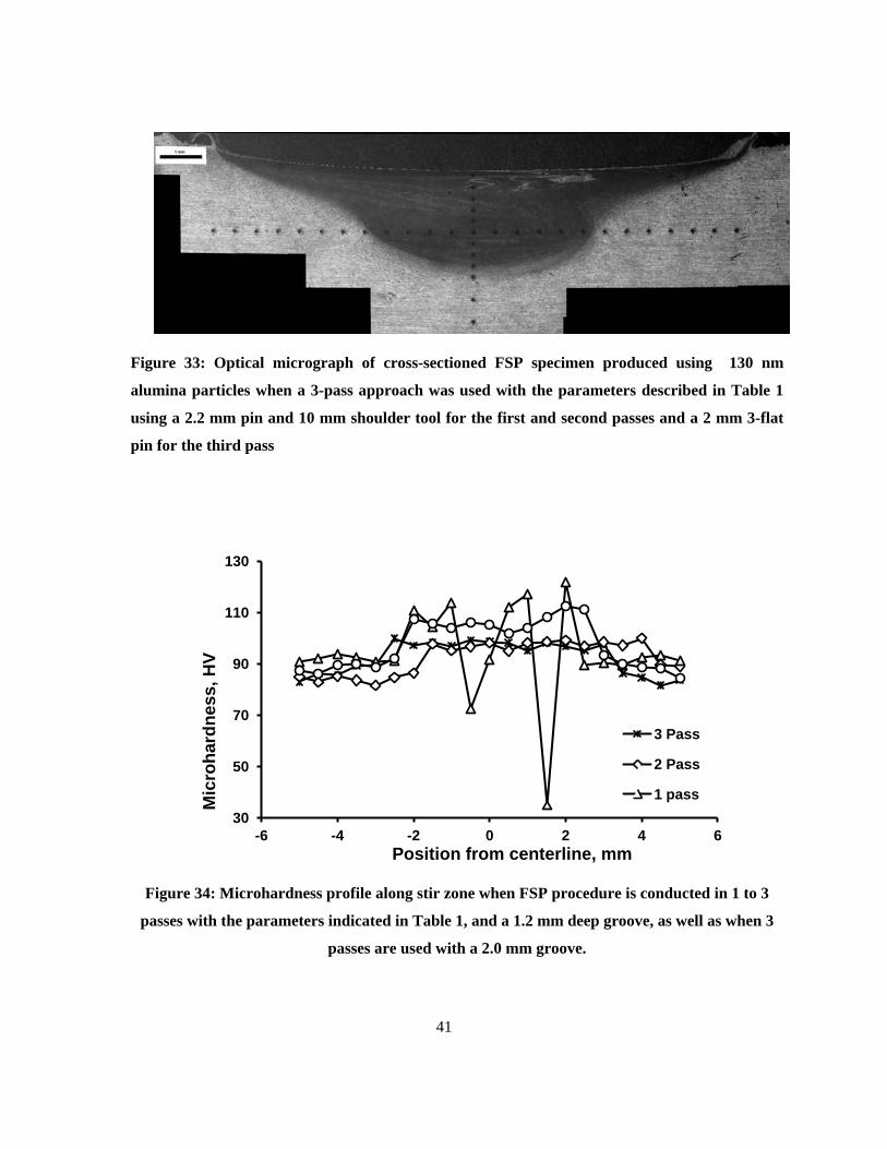
Figure 33: Optical micrograph of cross-sectioned FSP specimen produced using 130 nm alumina
particles when a 3-pass approach was used with the parameters described in Table 1 using a
2.2 mm pin and 10 mm shoulder tool for the first and second passes and a 2 mm 3-flat pin
for the third pass ................................................................................................................... 41
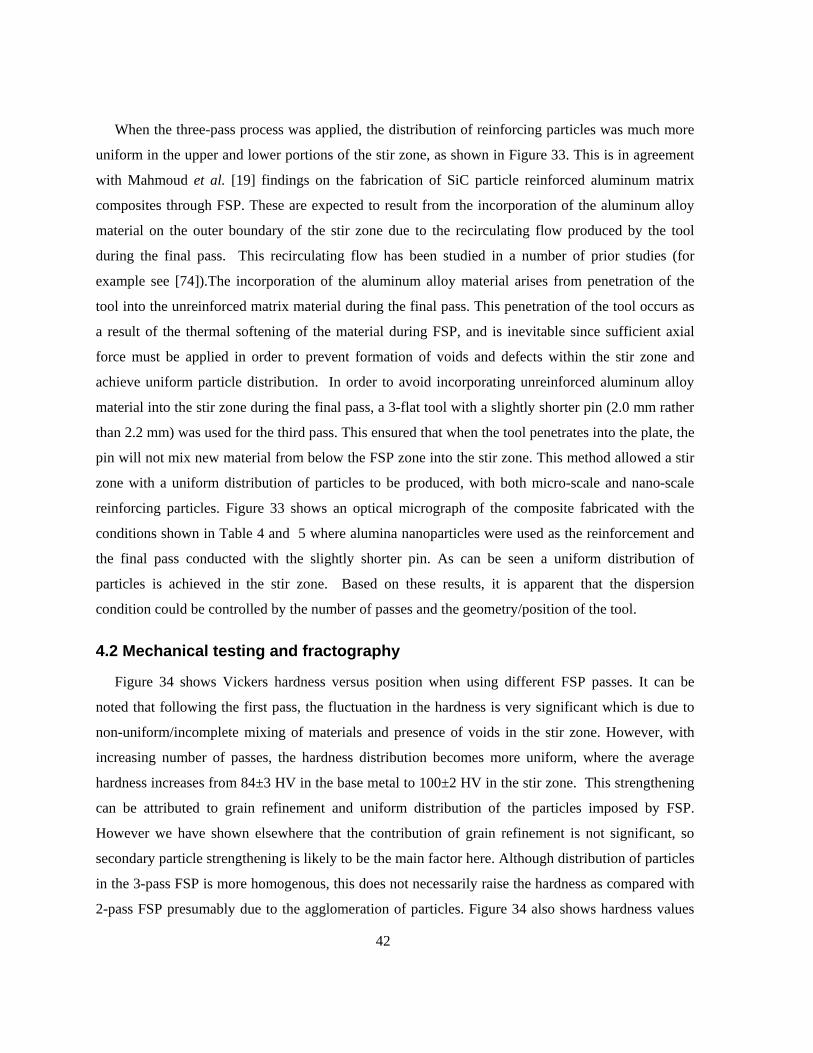
Figure 34: Microhardness profile along stir zone when FSP procedure is conducted in 1 to 3 passes
with the parameters indicated in Table 1, and a 1.2 mm deep groove, as well as when 3
passes are used with a 2.0 mm groove. ................................................................................. 41
Figure 35: Microhardness profile along stir zone when FSP is conducted using different particles. .. 43
Figure 36: Average stir zone hardness value versus particle volume fraction for various composites
produced by FSP. .................................................................................................................. 44
Figure 37: Scanning electron micrographs of friction stir processed samples containing a, b) 4.3 µm
Al2O3 and c, d) 1.1µm Al2O3. ............................................................................................... 46
Figure 38: Size distribution of alumina particles in FSP composites produced using 1.1 µm vs. 4.3 µm
Al2O3 particles. ..................................................................................................................... 47
Figure 39: Tensile test results of FSP composites as compared with the base metal (Al 5059). ......... 48

ix
Figure 40: Work hardening rate against the true plastic strain in friction stir proceed composites and
base metal. ............................................................................................................................. 50
Figure 41: Fracture surface of Al2O3 (130 nm), SiC, and B4C reinforced composites. ..................... 51
x
List of Tables Table 1: A Summary of Superplastic Properties of FSP Aluminum and Magnesium Alloys ............. 21
Table 2 : Summary of the investigations on nanocomposite fabrication using FSP ............................ 30
Table 3: Nominal composition of Al 5059 .......................................................................................... 32
Table 4: Processing parameters used in the FSP operations with 3-pass technique; travel speeds were
30 mm/min ............................................................................................................................ 35
Table 5: Summary of FSP Parameters applied .................................................................................... 36
Table 6: Mechanical characteristics of base material and friction stir processed components ............ 48
.
1
Chapter 1 Introduction
Friction stir processing (FSP) is a solid state material processing technique based on the principles
of friction stir welding developed by The Welding Institute (TWI) in 1991[1] [2]. The severe plastic
deformation and stirring action imposed by the tool during FSP has created many interesting
applications for this process [3]. Examples are microstructural modification and homogenization of
cast alloys and powder metallurgy fabricated parts [1, 4-9] and production and homogenization of
metal matrix composites [10-16]. In particular, composite fabrication by FSP has recently attracted
much interest and a great deal of research work has been done on this subject. Production of defect-
free bulk and surface composites has been reported for different MMCs such as aluminum matrix
composites (Al/SiC [17-21], Al/Al2O3 [22, 23], Al/NiTi [24], Al/CNT [25-27], Al/Fullerene [28],
Al/Ni [29], Al/TiO2 [30]), magnesium matrix composites (AZ31/nano ZrO2 and nano SiO2 [31],
AZ61/ SiO2 [16], AZ31/SiC [32], AZ31/CNT [15], AZ31/C60 [33]), copper matrix composites
(Cu/SiC [34], Cu/CNT [35]) and steel matrix composites (L316/SiC [36], mild steel/nano TiC [37]).
Generally the process involves the incorporation of the reinforcement into a groove or holes on the
surface of the metal matrix plate and then applying FSP to mix the two. When the stirring tool passes
through this material it effectively distributes the reinforcement within the matrix. However, in
addition to difficulties with particle distribution, an important issue that arises during use of this
method is how to minimize loss of the inserted particles during the process. This is important because
uncontrolled loss of reinforcement introduces the problem of control over the amount of
reinforcement, since the material loss makes it impossible to achieve a target percentage of secondary
material during the fabrication procedure. The most widely used solutionto this issue is to insert the
particles into the groove and perform one FSP pass with a cylindrical tool having no pin before
starting the actual FSP using the typical FSP tool [16, 22]. In a different approach Lim et al. [25] and
Mahmoud et al. [25, 38] have covered the groove with a thin plate and then applied FSP on this plate
along the groove. This method successfully prevents material loss, however making a bond between
the original plate and the “cover plate” remains an issue and needs special tool design and careful
control of other process parameters. Some other researchers [39-42] have used a more complicated
procedure; they have first prepared a powder preform using conventional powder metallurgy and then
inserted it into the groove. This method seems to be applicable for in-situ composites [40-42], or in
2
composites where the reinforcement is not a ceramic particle or nano-sized material [39], since
compacting such materials involves special equipment and high pressures.
Tool geometry and FSP process parameters are the key factors that may be altered to achieve
uniform distribution of the secondary material. It is shown that varying the process parameters may
affect particle distribution in different ways; by applying low axial force or low target depth, it has
been found that the particles will not distribute at all whereas with high axial force or high target
depth, all the particles will be pushed away from the pin surface. Hence, a moderate depth can
provide the best distribution [17, 23]. Increasing travel speed may lead to lower heat input which
could result in insufficient martial flow for optimal particle distribution [15], and so repeated FSP
passes may be needed to improve distribution by introducing more stirring and mixing [23, 31, 43]. It
is generally accepted that increasing the rotation speed and decreasing the travel speed improves
particle distribution [15, 44]. This is attributed to the better stirring and mixing as a result of higher
heat input. However, Mahmoud et al. have reported the best particle distribution was obtained by
decreasing the rotation speed to as low as possible to achieve a defect-free nugget, though no detailed
explanation of the reasons were provided [38, 43]. On the other hand, one should consider that
increasing the heat input results in larger grains in the final matrix microstructure [3] which is
detrimental to mechanical properties. Therefore optimum process parameters must be determined for
each specific application.
The effect of tool pin profile on particle distribution has been also investigated. Mahmoud et al.
[38] have shown that SiC particles were distributed more homogeneously in aluminum when a square
probe tool was used compared to circular or triangular probe tools [38]. Azizieh et al. have studied
the effect of threads and flutes on the surface of the pin in fabrication of AZ31/ Al2O3 composites by
FSP and reported the best particle distribution occurs with a threaded pin without flutes [44]. Vijay
and Murugan [45] have friction stir welded Al/TiB2 composite samples with tools having square,
hexagon or octagon pin geometry and concluded that a straight square pin achieves the best
mechanical properties [45], which implies a uniform TiB2 distribution is achieved. A similar approach
was used to produce Al 5059/MWCNT composite, as published elsewhere [27]. In particular, Al–B4C
composites offer not only the potential for surface hardening, but also the special capability in nuclear
applications to absorb thermal neutrons, thus it is being used as the main neutron shielding material in
the nuclear industry [46]. B4C provides outstanding physical and mechanical properties such as such
as high impact and wear resistance, low density, high melting point, high hardness, and good thermal
3
and electrical conductivity [47]. Therefore, a homogenous distribution of B4C particles in the matrix
is always desirable to achieve consistent neutron absorption properties.
In this study, a refined composite fabrication procedure via FSP is proposed. This new approach is
based on details of material flow imposed by different tool geometries and applies the effect of
process parameters to achieve uniform distribution of the secondary particles. Multiple FSP passes
were applied to promote material mixing, generating a uniform dispersion of particles. Different
reinforcing materials were examined to evaluate the applicability of the suggested technique.
Therefore, the objective of this work is to study the microstructure and the mechanical behavior of, Al
5059 matrix composites fabricated using the new FSP method and reinforced with various particle
types and sizes. The strengthening mechanism in mechanical behavior as determined using uniaxial
tensile and hardness tests, and fracture behaviour of the friction stir processed particle reinforced
composites are then discussed and compared in detail.
4
Chapter 2 Literature review
2.1 Composite Materials
A composite is a material consisting of two or more materials that are synthetically made, dissimilar
to one that develops naturally. A composite material, also, must include chemically different
constituent phases which are separated by a clear interface. Although, most metallic alloys and many
ceramics have multiple phases, they not fit this definition because they materialize as a result of
natural phenomena. Numerous composite materials are comprised of just two phases; one is known as
the matrix, which continuously surrounds the other constituent, which is called the dispersed phase.
The properties of the component phases (i.e., volume fraction, shape, and size of particles,
distribution, and orientation) define the properties of the composite[48].
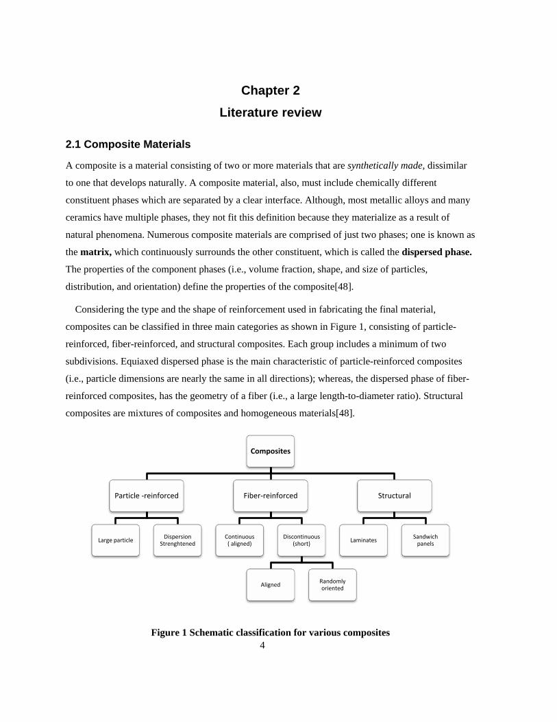
Considering the type and the shape of reinforcement used in fabricating the final material,
composites can be classified in three main categories as shown in Figure 1, consisting of particle-
reinforced, fiber-reinforced, and structural composites. Each group includes a minimum of two
subdivisions. Equiaxed dispersed phase is the main characteristic of particle-reinforced composites
(i.e., particle dimensions are nearly the same in all directions); whereas, the dispersed phase of fiber-
reinforced composites, has the geometry of a fiber (i.e., a large length-to-diameter ratio). Structural
composites are mixtures of composites and homogeneous materials[48].
Figure 1 Schematic classification for various composites
Composites
Particle -reinforced
Large particle Dispersion Strenghtened
Fiber-reinforced
Continuous ( aligned)
Discontinuous (short)
Aligned Randomly oriented
Structural
Laminates Sandwich panels
5
2.1.1 Particle reinforced composites
Particle-reinforced composites are consisting of two sub- divisions can be found as either large-
particle or dispersion-strengthened composites. These two categories are distinguished by
strengthening mechanism that is used to form the composite. When the particle–matrix relations
cannot be discussed on the atomic or molecular level, the term “large-particle” is used. The majority
of composites in this category consist of harder particulate phases than matrix material. The
strengthening particles detain movement of the matrix phase in the neighborhood of each particle. In
fact, a portion of utilized stress is conveyed to the particles by matrix. Robust bonding at the matrix–
particle interface plays an important role in improvement of mechanical behavior of composites. An
example of large-particle composite is concrete, which is constituted of cement (the matrix), and sand
and gravel (the particulates) [48].
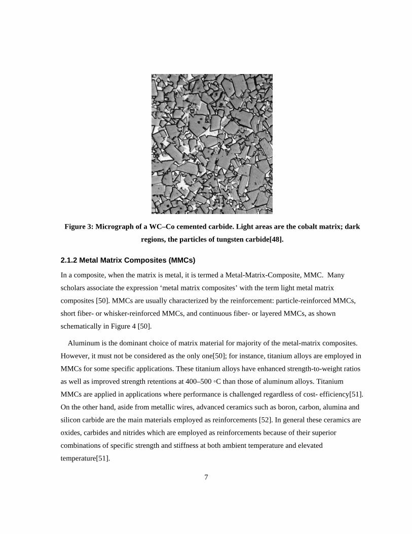
All three material types (metals, polymers, and ceramics) can be applied to develop large-particle
composites. Cermets for instance are categorized as large particle ceramic–metal composites. The
cemented carbide is the most common cermet which is combined of enormously stiff particles of a
refractory carbide ceramic such as tungsten carbide (WC) or titanium carbide (TiC), surrounded in a
matrix of a metal such as cobalt or nickel. Cutting tools for hardened steels are widely made out of
these type of composites[48].
In contrast to large particle composites, dispersion-strengthened composites include particles with
diameters between 10 and 100 nm. The strengthening of the material due to inclusion of the particles
takes place on the atomic or molecular level as a result of particle–matrix interactions. The
mechanism of strengthening is similar to that for precipitation hardening. The small dispersed
particles obstruct the movement of dislocations while the matrix tolerates the major portion of an
applied load. Thus, restriction of plastic deformation results in improving yield and tensile strengths,
as well as hardness. Efficient strengthening occurs when the particles are small and uniformly
dispersed throughout the matrix. The effectiveness of dispersion strengthening is not as prominent as
with precipitation hardening; however, since the dispersed particles are generally have to be not
reactive with the matrix phase in dispersion strengthened materials, the strengthening is maintained at
higher temperatures and for longer time periods. For precipitation-hardened alloys, the improvement
in strength may diminish upon heat treatment as a result of precipitate growth or dissolution of the
precipitate phase in the matrix material.
6
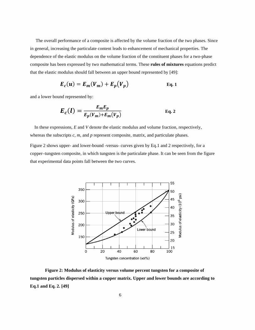
The overall performance of a composite is affected by the volume fraction of the two phases. Since
in general, increasing the particulate content leads to enhancement of mechanical properties. The
dependence of the elastic modulus on the volume fraction of the constituent phases for a two-phase
composite has been expressed by two mathematical terms. These rules of mixtures equations predict
that the elastic modulus should fall between an upper bound represented by [49]:
𝑬𝒄(𝒖) = 𝑬𝒎(𝑽𝒎) + 𝑬𝒑�𝑽𝒑� Eq. 1
and a lower bound represented by:
𝑬𝒄(𝒍) = 𝑬𝒎𝑬𝒑𝑬𝒑(𝑽𝒎)+𝑬𝒎�𝑽𝒑�
Eq. 2
In these expressions, E and V denote the elastic modulus and volume fraction, respectively,
whereas the subscripts c, m, and p represent composite, matrix, and particulate phases.
Figure 2 shows upper- and lower-bound -versus- curves given by Eq.1 and 2 respectively, for a
copper–tungsten composite, in which tungsten is the particulate phase. It can be seen from the figure
that experimental data points fall between the two curves.
Figure 2: Modulus of elasticity versus volume percent tungsten for a composite of
tungsten particles dispersed within a copper matrix. Upper and lower bounds are according to
Eq.1 and Eq. 2. [49]
7
Figure 3: Micrograph of a WC–Co cemented carbide. Light areas are the cobalt matrix; dark
regions, the particles of tungsten carbide[48].
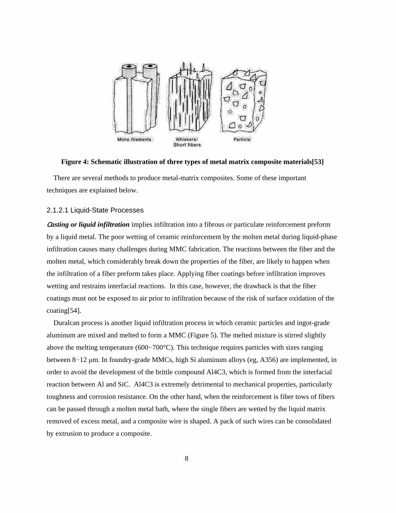
2.1.2 Metal Matrix Composites (MMCs)
In a composite, when the matrix is metal, it is termed a Metal-Matrix-Composite, MMC. Many
scholars associate the expression ‘metal matrix composites’ with the term light metal matrix
composites [50]. MMCs are usually characterized by the reinforcement: particle-reinforced MMCs,
short fiber- or whisker-reinforced MMCs, and continuous fiber- or layered MMCs, as shown
schematically in Figure 4 [50].
Aluminum is the dominant choice of matrix material for majority of the metal-matrix composites.
However, it must not be considered as the only one[50]; for instance, titanium alloys are employed in
MMCs for some specific applications. These titanium alloys have enhanced strength-to-weight ratios
as well as improved strength retentions at 400–500 ◦C than those of aluminum alloys. Titanium
MMCs are applied in applications where performance is challenged regardless of cost- efficiency[51].
On the other hand, aside from metallic wires, advanced ceramics such as boron, carbon, alumina and
silicon carbide are the main materials employed as reinforcements [52]. In general these ceramics are
oxides, carbides and nitrides which are employed as reinforcements because of their superior
combinations of specific strength and stiffness at both ambient temperature and elevated
temperature[51].
8
Figure 4: Schematic illustration of three types of metal matrix composite materials[53]
There are several methods to produce metal-matrix composites. Some of these important
techniques are explained below.
2.1.2.1 Liquid-State Processes
Casting or liquid infiltration implies infiltration into a fibrous or particulate reinforcement preform
by a liquid metal. The poor wetting of ceramic reinforcement by the molten metal during liquid-phase
infiltration causes many challenges during MMC fabrication. The reactions between the fiber and the
molten metal, which considerably break down the properties of the fiber, are likely to happen when
the infiltration of a fiber preform takes place. Applying fiber coatings before infiltration improves
wetting and restrains interfacial reactions. In this case, however, the drawback is that the fiber
coatings must not be exposed to air prior to infiltration because of the risk of surface oxidation of the
coating[54].
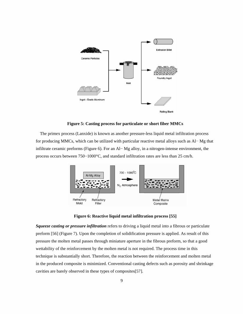
Duralcan process is another liquid infiltration process in which ceramic particles and ingot-grade
aluminum are mixed and melted to form a MMC (Figure 5). The melted mixture is stirred slightly
above the melting temperature (600−700°C). This technique requires particles with sizes ranging
between 8−12 μm. In foundry-grade MMCs, high Si aluminum alloys (eg, A356) are implemented, in
order to avoid the development of the brittle compound Al4C3, which is formed from the interfacial
reaction between Al and SiC. Al4C3 is extremely detrimental to mechanical properties, particularly
toughness and corrosion resistance. On the other hand, when the reinforcement is fiber tows of fibers
can be passed through a molten metal bath, where the single fibers are wetted by the liquid matrix
removed of excess metal, and a composite wire is shaped. A pack of such wires can be consolidated
by extrusion to produce a composite.
9
Figure 5: Casting process for particulate or short fiber MMCs
The primex process (Lanxide) is known as another pressure-less liquid metal infiltration process
for producing MMCs, which can be utilized with particular reactive metal alloys such as Al− Mg that
infiltrate ceramic preforms (Figure 6). For an Al− Mg alloy, in a nitrogen-intense environment, the
process occurs between 750−1000°C, and standard infiltration rates are less than 25 cm/h.
Figure 6: Reactive liquid metal infiltration process [55]
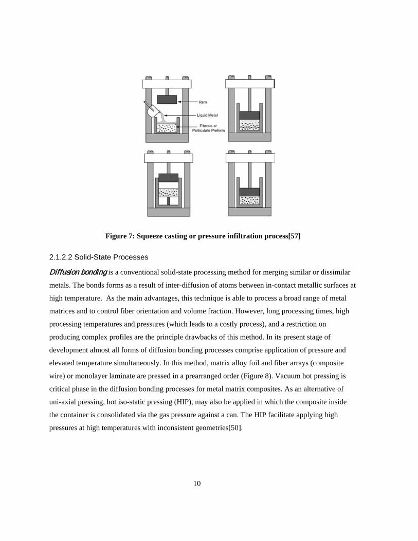
Squeeze casting or pressure infiltration refers to driving a liquid metal into a fibrous or particulate
preform [56] (Figure 7). Upon the completion of solidification pressure is applied. As result of this
pressure the molten metal passes through miniature aperture in the fibrous preform, so that a good
wettability of the reinforcement by the molten metal is not required. The process time in this
technique is substantially short. Therefore, the reaction between the reinforcement and molten metal
in the produced composite is minimized. Conventional casting defects such as porosity and shrinkage
cavities are barely observed in these types of composites[57].
10
Figure 7: Squeeze casting or pressure infiltration process[57]
2.1.2.2 Solid-State Processes
Diffusion bonding is a conventional solid-state processing method for merging similar or dissimilar
metals. The bonds forms as a result of inter-diffusion of atoms between in-contact metallic surfaces at
high temperature. As the main advantages, this technique is able to process a broad range of metal
matrices and to control fiber orientation and volume fraction. However, long processing times, high
processing temperatures and pressures (which leads to a costly process), and a restriction on
producing complex profiles are the principle drawbacks of this method. In its present stage of
development almost all forms of diffusion bonding processes comprise application of pressure and
elevated temperature simultaneously. In this method, matrix alloy foil and fiber arrays (composite
wire) or monolayer laminate are pressed in a prearranged order (Figure 8). Vacuum hot pressing is
critical phase in the diffusion bonding processes for metal matrix composites. As an alternative of
uni-axial pressing, hot iso-static pressing (HIP), may also be applied in which the composite inside
the container is consolidated via the gas pressure against a can. The HIP facilitate applying high
pressures at high temperatures with inconsistent geometries[50].
11
Figure 8: Diffusion bonding process: (a) apply metal foil and cut to shape, (b) layup desired
plies, (c) vacuum encapsulate and heat to fabrication temperature, (d) apply pressure and hold
for consolidation cycle, and (e) cool, remove, and clean part [50].
Deformation processing is another solid state technique in which the composite material is deformed
and/or densified. Mechanical processing (swaging, extrusion, drawing, or rolling) of a ductile two-
phases metal−metal composite triggers the two phases to co-deform, leading to one of the phases to
elongate and become fibrous in nature within the other phase. The materials produced are
occasionally denoted as in-situ composites. The characteristics of the preliminary materials define the
properties of a deformation processed composite. The initial materials are normally a billet of a two-
phase alloy that has been made by casting or powder metallurgy methods[58].
Another conventional practice to produce a laminated composite is roll bonding. The produced
composite by this technique consists of distinct metals in layered arrangement which is called sheet
laminated metal-matrix composites[59]. The process of producing a laminated MMC using the roll
bonding technique is schematically shown in Figure 9.
Figure 9: Roll bonding process of making a laminated MMC; a metallurgical bond is produced
[59]
12
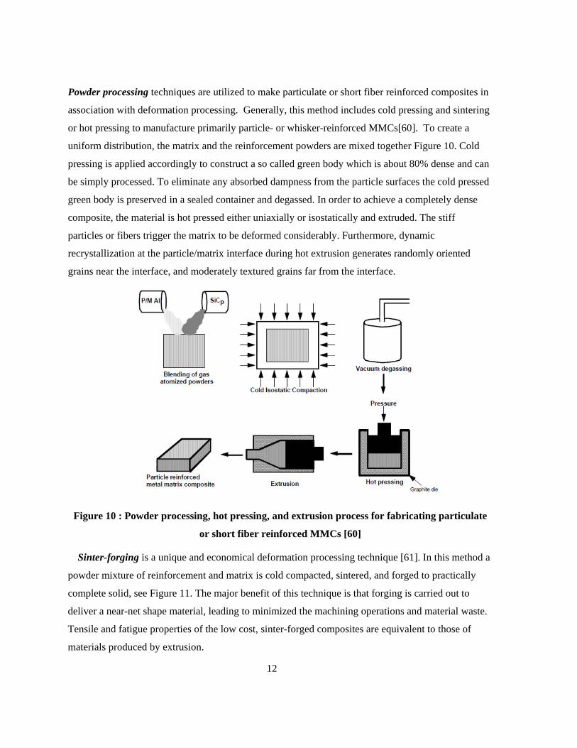
Powder processing techniques are utilized to make particulate or short fiber reinforced composites in
association with deformation processing. Generally, this method includes cold pressing and sintering
or hot pressing to manufacture primarily particle- or whisker-reinforced MMCs[60]. To create a
uniform distribution, the matrix and the reinforcement powders are mixed together Figure 10. Cold
pressing is applied accordingly to construct a so called green body which is about 80% dense and can
be simply processed. To eliminate any absorbed dampness from the particle surfaces the cold pressed
green body is preserved in a sealed container and degassed. In order to achieve a completely dense
composite, the material is hot pressed either uniaxially or isostatically and extruded. The stiff
particles or fibers trigger the matrix to be deformed considerably. Furthermore, dynamic
recrystallization at the particle/matrix interface during hot extrusion generates randomly oriented
grains near the interface, and moderately textured grains far from the interface.
Figure 10 : Powder processing, hot pressing, and extrusion process for fabricating particulate
or short fiber reinforced MMCs [60]
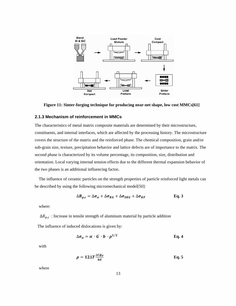
Sinter-forging is a unique and economical deformation processing technique [61]. In this method a
powder mixture of reinforcement and matrix is cold compacted, sintered, and forged to practically
complete solid, see Figure 11. The major benefit of this technique is that forging is carried out to
deliver a near-net shape material, leading to minimized the machining operations and material waste.
Tensile and fatigue properties of the low cost, sinter-forged composites are equivalent to those of
materials produced by extrusion.
13
Figure 11: Sinter-forging technique for producing near-net shape, low cost MMCs[61]
2.1.3 Mechanism of reinforcement in MMCs
The characteristics of metal matrix composite materials are determined by their microstructure,
constituents, and internal interfaces, which are affected by the processing history. The microstructure
covers the structure of the matrix and the reinforced phase. The chemical composition, grain and/or
sub-grain size, texture, precipitation behavior and lattice defects are of importance to the matrix. The
second phase is characterized by its volume percentage, its composition, size, distribution and
orientation. Local varying internal tension effects due to the different thermal expansion behavior of
the two phases is an additional influencing factor.
The influence of ceramic particles on the strength properties of particle reinforced light metals can
be described by using the following micromechanical model[50]:
∆𝑹𝒑,𝒄 = ∆𝝈𝜶 + ∆𝝈𝑲𝑮 + ∆𝝈𝑺𝑲𝑮 + ∆𝝈𝑲𝑭 Eq. 3
where:
∆𝑅𝑝,𝑐 : Increase in tensile strength of aluminum material by particle addition
The influence of induced dislocations is given by:
∆𝝈𝜶 = 𝜶 ∙ 𝑮 ∙ 𝒃 ∙ 𝝆𝟏 𝟐⁄ Eq. 4
with
𝝆 = 𝟏𝟐∆𝑻 ∆𝑪𝝓𝑷𝒃𝒅
Eq. 5
where

14
∆𝜎𝛼: The yield strength contribution due to geometrical necessary dislocations and inner tension.
𝛼 : Constant (values 0.5-1)
𝐺 : The shear modulus
𝑏 : The burger’s vector
𝜌 : The dislocation density
∆𝑇 : Temperature difference
∆𝐶 : The difference in thermal expansion coefficient between matrix and particle
𝜙𝑃 : The particle volume fraction
𝑑 : Particle size
The influence of grain size is given by:
∆𝝈𝑲𝑮 = 𝒌𝒀𝟏𝑫−𝟏 𝟐⁄ Eq. 6
with
𝑫 = 𝒅 �𝟏−𝝓𝑷𝝓𝑷
�𝟏 𝟑⁄
Eq. 7
where
∆𝜎𝐾𝐺: The yield strength contribution from changes in grain size (for example recrystallization
during thermomechanical treatment of composite materials analogue Hall-Petch)
∆𝝈𝑺𝑲𝑮 = 𝒌𝒀𝟐𝑫𝒔−𝟏 𝟐⁄ Eq. 8
With
𝑫𝒔 = 𝒅 �𝝅𝒅𝟐
𝟔𝝓𝑷�𝟏 𝟐⁄
Eq. 9
where
∆𝜎𝑆𝐾𝐺: The yield strength contribution due to changes in sub grain size
𝑘𝑌2: Constant (values 0.05 MN m-3/2 )
𝐷𝑠 : Resulting sub grain size
𝜙𝑃 : The particle volume fraction
15
And
∆𝝈𝑲𝑭 = 𝑲𝑮𝝓𝑷 �𝟐𝒃𝒅�𝟏 𝟐⁄
. 𝜺𝟏 𝟐⁄ Eq. 10
where
𝐾: Constant
𝐺: shear modulus
𝜙𝑃 : The particle volume fraction
𝑏: The Burger’s vector
𝑑: particle diameter
𝜀: The elongation
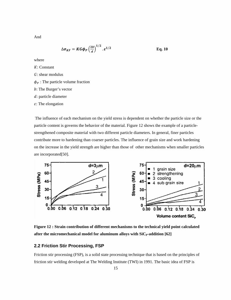
The influence of each mechanism on the yield stress is dependent on whether the particle size or the
particle content is governs the behavior of the material. Figure 12 shows the example of a particle-
strengthened composite material with two different particle diameters. In general, finer particles
contribute more to hardening than coarser particles. The influence of grain size and work hardening
on the increase in the yield strength are higher than those of other mechanisms when smaller particles
are incorporated[50].
Figure 12 : Strain contribution of different mechanisms to the technical yield point calculated
after the micromechanical model for aluminum alloys with SiCP-addition [62]
2.2 Friction Stir Processing, FSP
Friction stir processing (FSP), is a solid state processing technique that is based on the principles of
friction stir welding developed at The Welding Institute (TWI) in 1991. The basic idea of FSP is
16
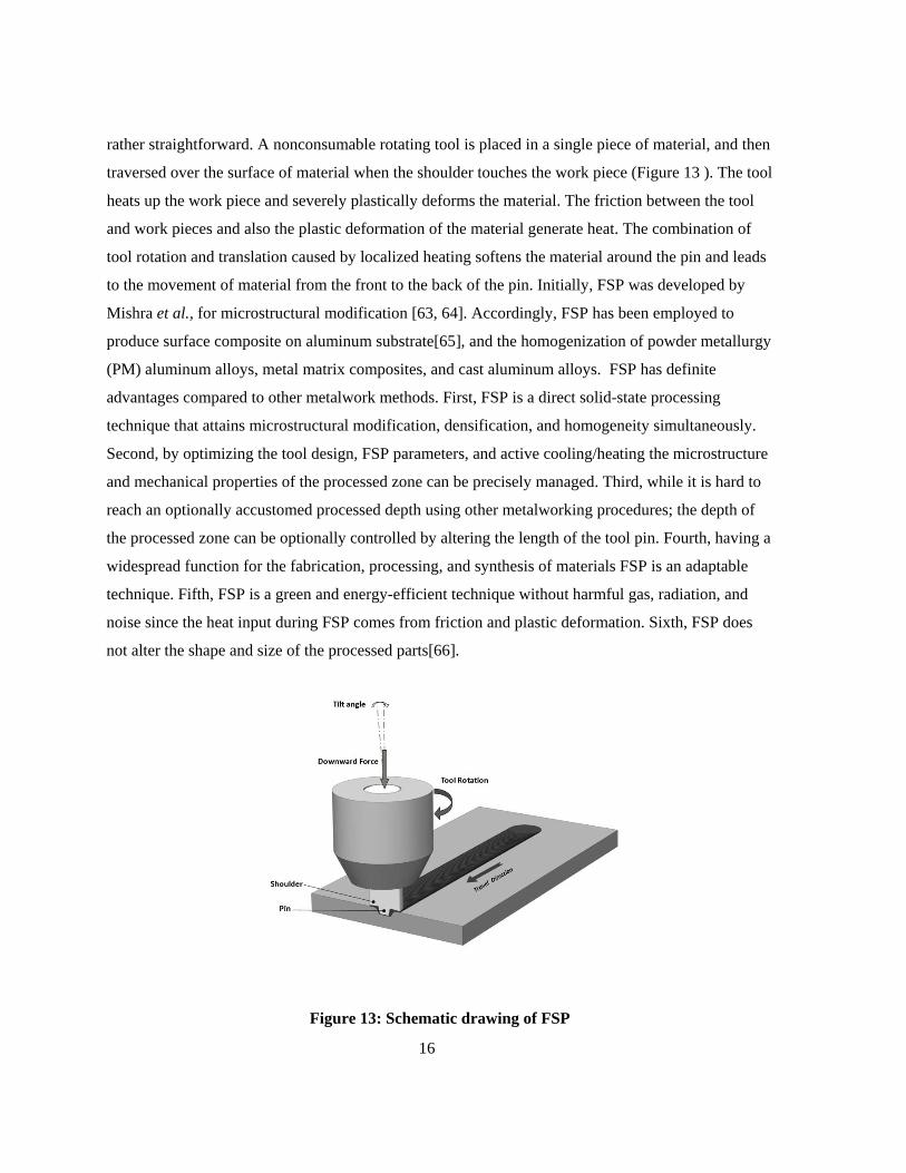
rather straightforward. A nonconsumable rotating tool is placed in a single piece of material, and then
traversed over the surface of material when the shoulder touches the work piece (Figure 13 ). The tool
heats up the work piece and severely plastically deforms the material. The friction between the tool
and work pieces and also the plastic deformation of the material generate heat. The combination of
tool rotation and translation caused by localized heating softens the material around the pin and leads
to the movement of material from the front to the back of the pin. Initially, FSP was developed by
Mishra et al., for microstructural modification [63, 64]. Accordingly, FSP has been employed to
produce surface composite on aluminum substrate[65], and the homogenization of powder metallurgy
(PM) aluminum alloys, metal matrix composites, and cast aluminum alloys. FSP has definite
advantages compared to other metalwork methods. First, FSP is a direct solid-state processing
technique that attains microstructural modification, densification, and homogeneity simultaneously.
Second, by optimizing the tool design, FSP parameters, and active cooling/heating the microstructure
and mechanical properties of the processed zone can be precisely managed. Third, while it is hard to
reach an optionally accustomed processed depth using other metalworking procedures; the depth of
the processed zone can be optionally controlled by altering the length of the tool pin. Fourth, having a
widespread function for the fabrication, processing, and synthesis of materials FSP is an adaptable
technique. Fifth, FSP is a green and energy-efficient technique without harmful gas, radiation, and
noise since the heat input during FSP comes from friction and plastic deformation. Sixth, FSP does
not alter the shape and size of the processed parts[66].
Figure 13: Schematic drawing of FSP
17
2.2.1 Microstructure evolution during FSP
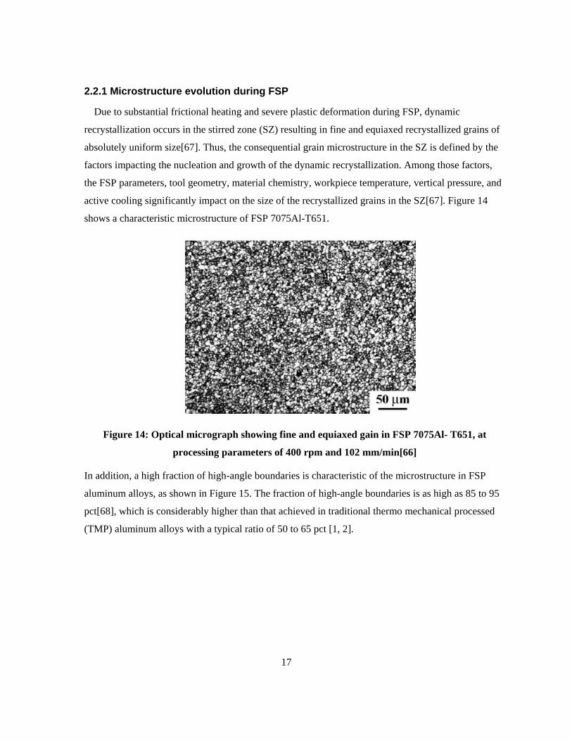
Due to substantial frictional heating and severe plastic deformation during FSP, dynamic
recrystallization occurs in the stirred zone (SZ) resulting in fine and equiaxed recrystallized grains of
absolutely uniform size[67]. Thus, the consequential grain microstructure in the SZ is defined by the
factors impacting the nucleation and growth of the dynamic recrystallization. Among those factors,
the FSP parameters, tool geometry, material chemistry, workpiece temperature, vertical pressure, and
active cooling significantly impact on the size of the recrystallized grains in the SZ[67]. Figure 14
shows a characteristic microstructure of FSP 7075Al-T651.
Figure 14: Optical micrograph showing fine and equiaxed gain in FSP 7075Al- T651, at
processing parameters of 400 rpm and 102 mm/min[66]
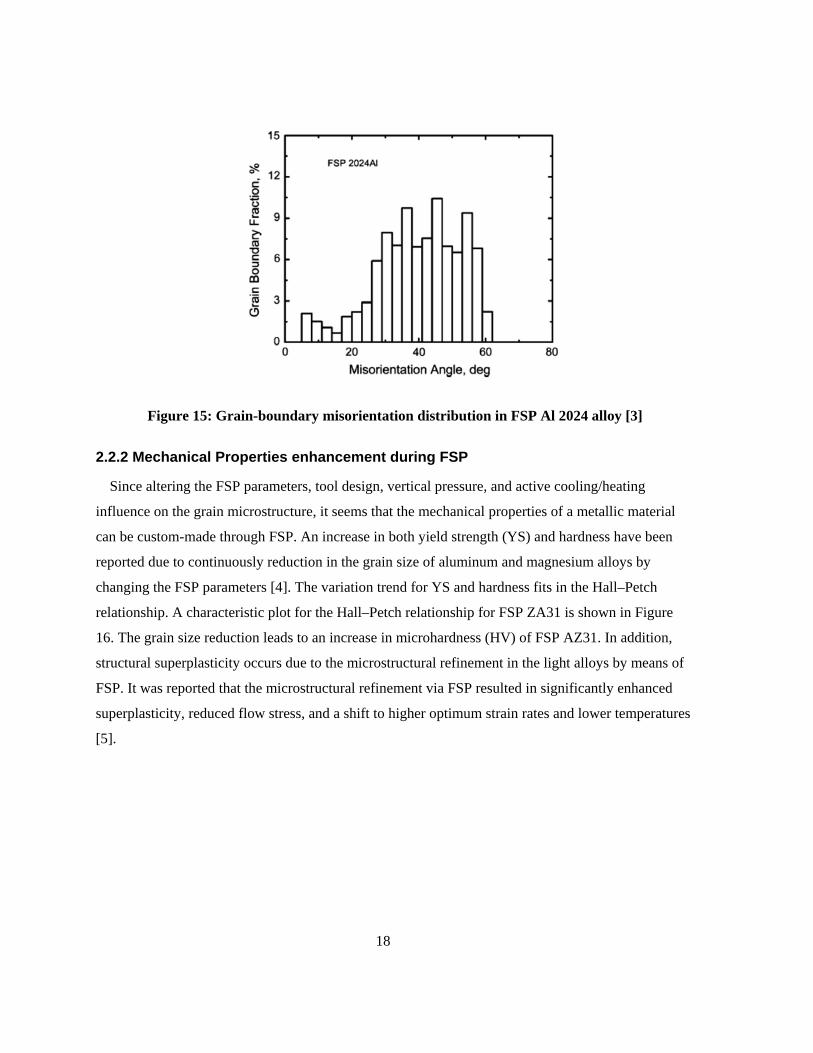
In addition, a high fraction of high-angle boundaries is characteristic of the microstructure in FSP
aluminum alloys, as shown in Figure 15. The fraction of high-angle boundaries is as high as 85 to 95
pct[68], which is considerably higher than that achieved in traditional thermo mechanical processed
(TMP) aluminum alloys with a typical ratio of 50 to 65 pct [1, 2].
18
Figure 15: Grain-boundary misorientation distribution in FSP Al 2024 alloy [3]
2.2.2 Mechanical Properties enhancement during FSP
Since altering the FSP parameters, tool design, vertical pressure, and active cooling/heating
influence on the grain microstructure, it seems that the mechanical properties of a metallic material
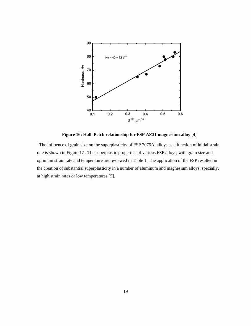
can be custom-made through FSP. An increase in both yield strength (YS) and hardness have been
reported due to continuously reduction in the grain size of aluminum and magnesium alloys by
changing the FSP parameters [4]. The variation trend for YS and hardness fits in the Hall–Petch
relationship. A characteristic plot for the Hall–Petch relationship for FSP ZA31 is shown in Figure
16. The grain size reduction leads to an increase in microhardness (HV) of FSP AZ31. In addition,
structural superplasticity occurs due to the microstructural refinement in the light alloys by means of
FSP. It was reported that the microstructural refinement via FSP resulted in significantly enhanced
superplasticity, reduced flow stress, and a shift to higher optimum strain rates and lower temperatures
[5].
19
Figure 16: Hall–Petch relationship for FSP AZ31 magnesium alloy [4]
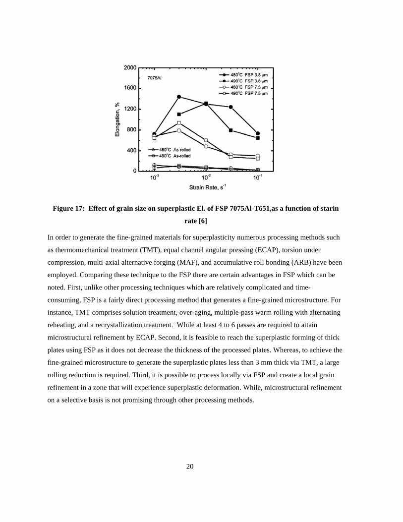
The influence of grain size on the superplasticity of FSP 7075Al alloys as a function of initial strain
rate is shown in Figure 17 . The superplastic properties of various FSP alloys, with grain size and
optimum strain rate and temperature are reviewed in Table 1. The application of the FSP resulted in
the creation of substantial superplasticity in a number of aluminum and magnesium alloys, specially,
at high strain rates or low temperatures [5].
20
Figure 17: Effect of grain size on superplastic El. of FSP 7075Al-T651,as a function of starin
rate [6]
In order to generate the fine-grained materials for superplasticity numerous processing methods such
as thermomechanical treatment (TMT), equal channel angular pressing (ECAP), torsion under
compression, multi-axial alternative forging (MAF), and accumulative roll bonding (ARB) have been
employed. Comparing these technique to the FSP there are certain advantages in FSP which can be
noted. First, unlike other processing techniques which are relatively complicated and time-
consuming, FSP is a fairly direct processing method that generates a fine-grained microstructure. For
instance, TMT comprises solution treatment, over-aging, multiple-pass warm rolling with alternating
reheating, and a recrystallization treatment. While at least 4 to 6 passes are required to attain
microstructural refinement by ECAP. Second, it is feasible to reach the superplastic forming of thick
plates using FSP as it does not decrease the thickness of the processed plates. Whereas, to achieve the
fine-grained microstructure to generate the superplastic plates less than 3 mm thick via TMT, a large
rolling reduction is required. Third, it is possible to process locally via FSP and create a local grain
refinement in a zone that will experience superplastic deformation. While, microstructural refinement
on a selective basis is not promising through other processing methods.
21
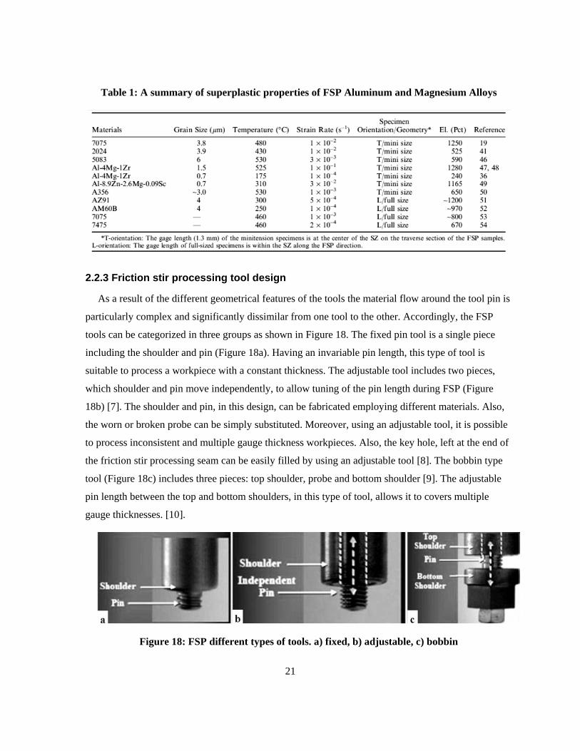
Table 1: A summary of superplastic properties of FSP Aluminum and Magnesium Alloys
2.2.3 Friction stir processing tool design
As a result of the different geometrical features of the tools the material flow around the tool pin is
particularly complex and significantly dissimilar from one tool to the other. Accordingly, the FSP
tools can be categorized in three groups as shown in Figure 18. The fixed pin tool is a single piece
including the shoulder and pin (Figure 18a). Having an invariable pin length, this type of tool is
suitable to process a workpiece with a constant thickness. The adjustable tool includes two pieces,
which shoulder and pin move independently, to allow tuning of the pin length during FSP (Figure
18b) [7]. The shoulder and pin, in this design, can be fabricated employing different materials. Also,
the worn or broken probe can be simply substituted. Moreover, using an adjustable tool, it is possible
to process inconsistent and multiple gauge thickness workpieces. Also, the key hole, left at the end of
the friction stir processing seam can be easily filled by using an adjustable tool [8]. The bobbin type
tool (Figure 18c) includes three pieces: top shoulder, probe and bottom shoulder [9]. The adjustable
pin length between the top and bottom shoulders, in this type of tool, allows it to covers multiple
gauge thicknesses. [10].
Figure 18: FSP different types of tools. a) fixed, b) adjustable, c) bobbin
22
2.2.3.1 Tool shapes
Tool shoulder components are basically designed to generate frictional heat and apply the required
downward force to consolidate and maintain the soften metal underneath of shoulder surface. The
standard shoulder outer surfaces, the bottom end surfaces and the end features are summarized in
Figure 19. Generally, the shoulder outer surface includes a cylindrical or conical profile. Since the
shoulder plunge depth is usually small (1–5% of the gauge thickness) the influence of the shape of the
shoulder outer surface (cylindrical or conical) is believed to be minor [11].
Three varieties of shoulder end surfaces are illustrated in Figure 19. The most straightforward
design is the flat shoulder end surface. This type of shoulder is not able to entrap the flowing material
under the shoulder surface and causes the formation of unwarranted material flash. A concave
shoulder end surface, however, is designed to restrict the material extrusion from the edges of the
shoulder [12]. Another viable end shape of the shoulder is a convex profile [13]. When using a
convex shoulder profile for joining to workpieces via friction stir welding, the major benefit is that
the contact with the workpiece can be achieved at any location down the convex end surface. Thus,
variation in flatness or thickness between the two adjoining workpieces can be easily adjusted. On the
other hand, the failure to avoid material displacement away from pin leads to an unreliable weld using
a convex shoulder profile [8].
23
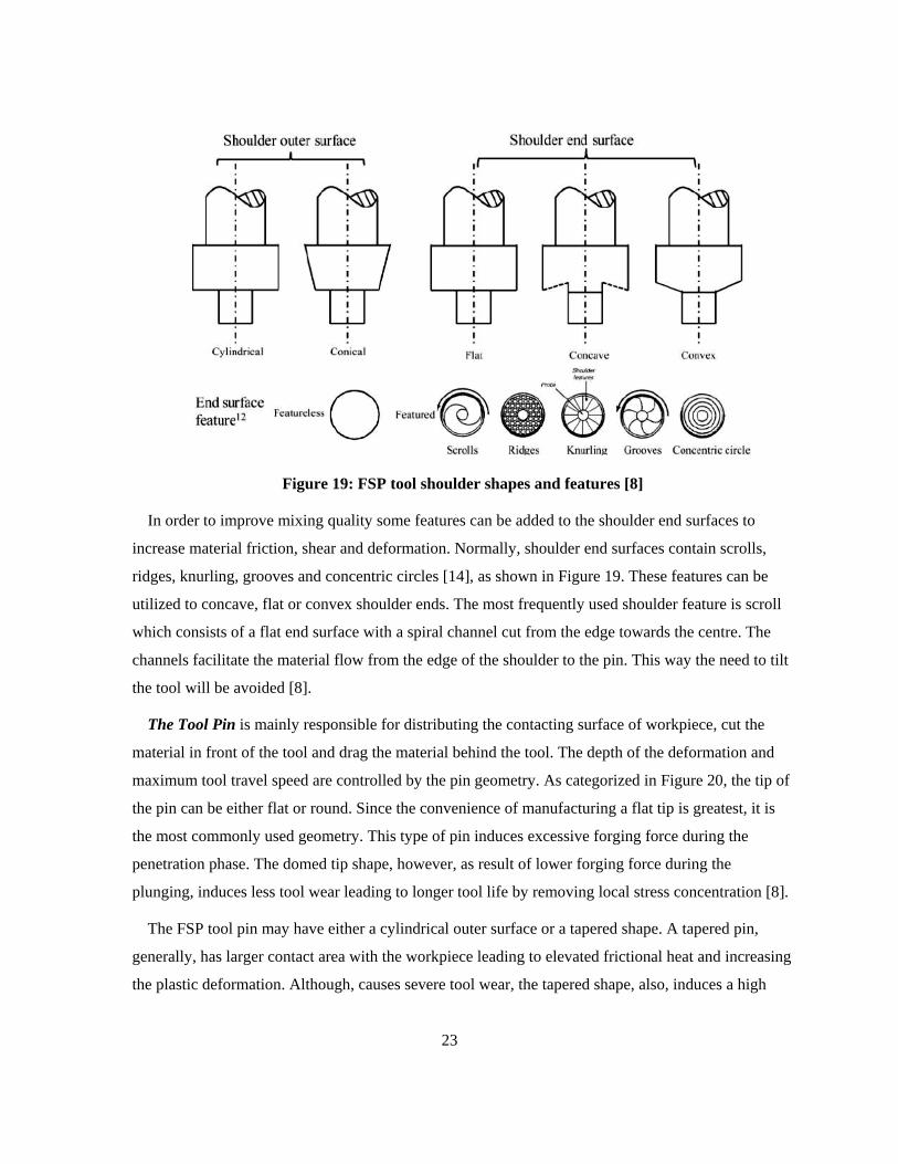
Figure 19: FSP tool shoulder shapes and features [8]
In order to improve mixing quality some features can be added to the shoulder end surfaces to
increase material friction, shear and deformation. Normally, shoulder end surfaces contain scrolls,
ridges, knurling, grooves and concentric circles [14], as shown in Figure 19. These features can be
utilized to concave, flat or convex shoulder ends. The most frequently used shoulder feature is scroll
which consists of a flat end surface with a spiral channel cut from the edge towards the centre. The
channels facilitate the material flow from the edge of the shoulder to the pin. This way the need to tilt
the tool will be avoided [8].
The Tool Pin is mainly responsible for distributing the contacting surface of workpiece, cut the
material in front of the tool and drag the material behind the tool. The depth of the deformation and
maximum tool travel speed are controlled by the pin geometry. As categorized in Figure 20, the tip of
the pin can be either flat or round. Since the convenience of manufacturing a flat tip is greatest, it is
the most commonly used geometry. This type of pin induces excessive forging force during the
penetration phase. The domed tip shape, however, as result of lower forging force during the
plunging, induces less tool wear leading to longer tool life by removing local stress concentration [8].
The FSP tool pin may have either a cylindrical outer surface or a tapered shape. A tapered pin,
generally, has larger contact area with the workpiece leading to elevated frictional heat and increasing
the plastic deformation. Although, causes severe tool wear, the tapered shape, also, induces a high
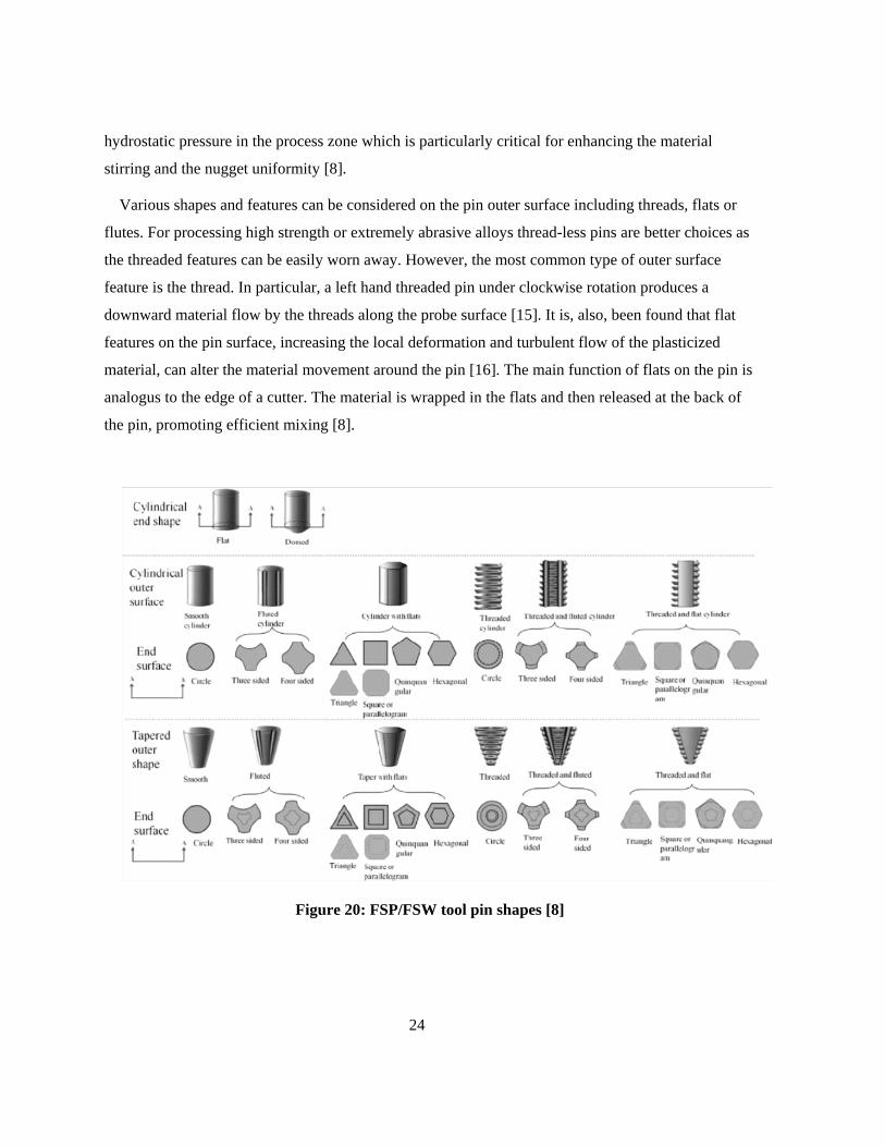
24
hydrostatic pressure in the process zone which is particularly critical for enhancing the material
stirring and the nugget uniformity [8].
Various shapes and features can be considered on the pin outer surface including threads, flats or
flutes. For processing high strength or extremely abrasive alloys thread-less pins are better choices as
the threaded features can be easily worn away. However, the most common type of outer surface
feature is the thread. In particular, a left hand threaded pin under clockwise rotation produces a
downward material flow by the threads along the probe surface [15]. It is, also, been found that flat
features on the pin surface, increasing the local deformation and turbulent flow of the plasticized
material, can alter the material movement around the pin [16]. The main function of flats on the pin is
analogus to the edge of a cutter. The material is wrapped in the flats and then released at the back of
the pin, promoting efficient mixing [8].
Figure 20: FSP/FSW tool pin shapes [8]
25
2.2.3.2 Tool dimensions
As demonstrated in Eq. 11, w…hile the heat input depends only linearly on the applied forging force
and the rotational speed is a function of the shoulder radius to the third power but [17]. Thus, the
energy input in FSP is especially dependent on the shoulder size. Furthermore, the downward forge
force is also a function of the shoulder radius.
𝒒𝟎 = 𝟒 𝟑⁄ 𝝅𝟐𝝁𝑷𝝎𝒓𝟑 Eq. 11
Where:
𝑞0: The net power (W)
𝜇: Effective friction coefficient
𝑃: Pressure (MPa)
𝜔: Rotation speed (RPM)
𝑟 : Shoulder radius (mm)
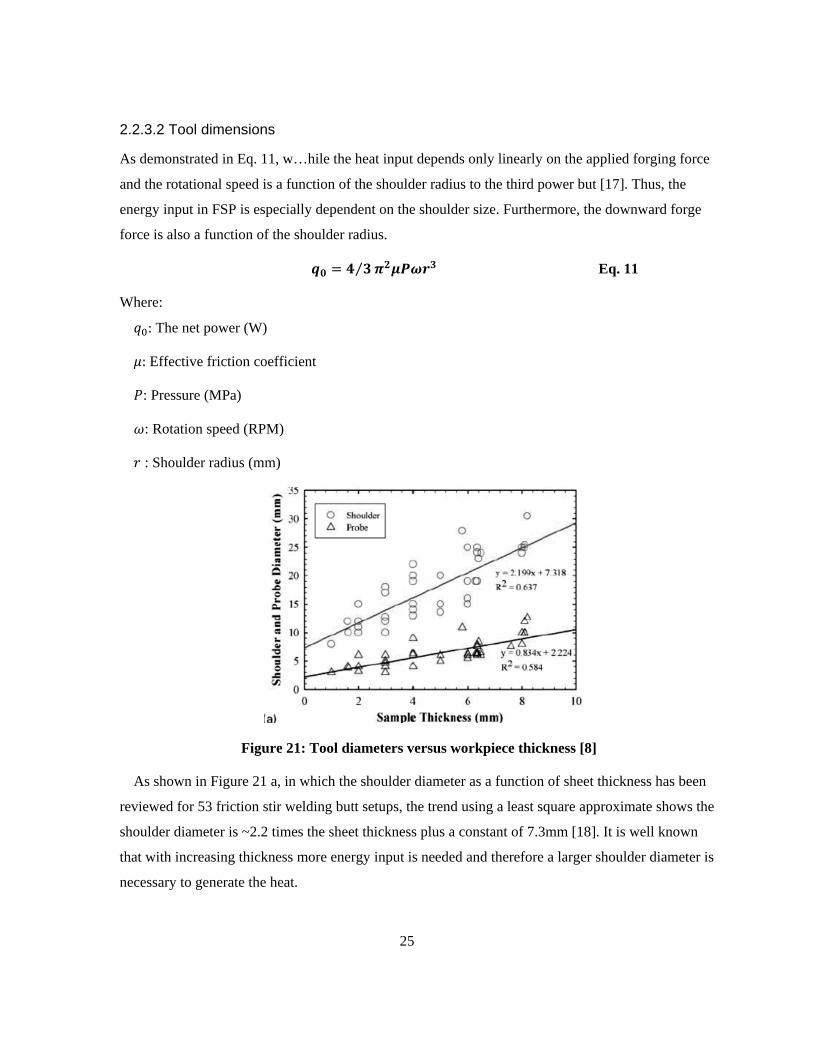
Figure 21: Tool diameters versus workpiece thickness [8]
As shown in Figure 21 a, in which the shoulder diameter as a function of sheet thickness has been
reviewed for 53 friction stir welding butt setups, the trend using a least square approximate shows the
shoulder diameter is ~2.2 times the sheet thickness plus a constant of 7.3mm [18]. It is well known
that with increasing thickness more energy input is needed and therefore a larger shoulder diameter is
necessary to generate the heat.

26
2.2.3.3 Tool materials
The workpiece material and the desired tool life are the two most crucial parameters to indicate the
tool material. The following characteristics should be considered when selecting tool material [8]:
a. Superior compressive yield strength at high temperature than the predictable forging force
onto tool.
b. Dimensional stability and creep resistance
c. High thermal fatigue strength to endure frequent heating and cooling cycles.
d. Zero destructive reaction with the workpiece material.
e. High fracture toughness to resist the forging force during penetration and dwelling.
f. Minimum coefficient of thermal expansion difference between the pin and the shoulder to
reduce the thermal stresses.
g. Good machinability to facilitate cutting complex features on the tool.
h. Reasonable cost.
The most commonly exercised tool material for processing aluminum alloys is tool steel. AISI H13
has been the most frequently used among tool steels. Nickel and cobalt based superalloys, having
great strength, ductility, excellent poor creep and corrosion resistance are superior candidate for tool
material. The only drawback back which impedes wide application of these superalloys is the
difficulty in machining complex features such as flutes and flats on the tool surface. In addition, high
temperature strength due to single phase structure of refractory metals, such as tungsten,
molybdenum, niobium and tantalum, leads to stable mechanical properties up to 1000-1500°C and
making them as good choices for tool material. However, relatively expensive fabrication process of
refractory metals (i.e., powder processing). At elevated temperature carbide materials, because of
their good wear resistance and sufficient fracture toughness are frequently employed as tool material.
Also, ceramic particle reinforced MMCs have been used as tool material although the brittle nature of
the composite raises the chance of fracture during the penetration phase. Furthermore, despite the
excellent mechanical and thermal properties, extensive application of polycrystalline cubic boron
nitride, PCBN, as FSP/FSW tool has been limited due to relatively high manufacturing costs, size
limitation and poor machinability [8].
27
2.2.3.4 Tool wear
Tool wears causes changes to the tool shape leading, potentially causing defects in the stir zone.
The tool material and geometry and process parameters define the precise wear mechanism. For
instance at low rotation speed the tool wear in PCBN is generally triggered by adhesive wear.
Whereas, at high rotation speed the wear is due to abrasive wear [19]. Tool wear has also been
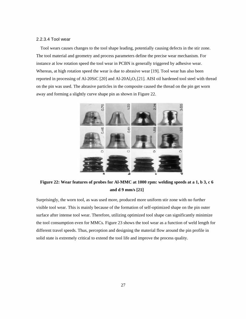
reported in processing of Al-20SiC [20] and Al-20Al2O3 [21]. AISI oil hardened tool steel with thread
on the pin was used. The abrasive particles in the composite caused the thread on the pin get worn
away and forming a slightly curve shape pin as shown in Figure 22.
Figure 22: Wear features of probes for Al-MMC at 1000 rpm: welding speeds at a 1, b 3, c 6
and d 9 mm/s [21]
Surprisingly, the worn tool, as was used more, produced more uniform stir zone with no further
visible tool wear. This is mainly because of the formation of self-optimized shape on the pin outer
surface after intense tool wear. Therefore, utilizing optimized tool shape can significantly minimize
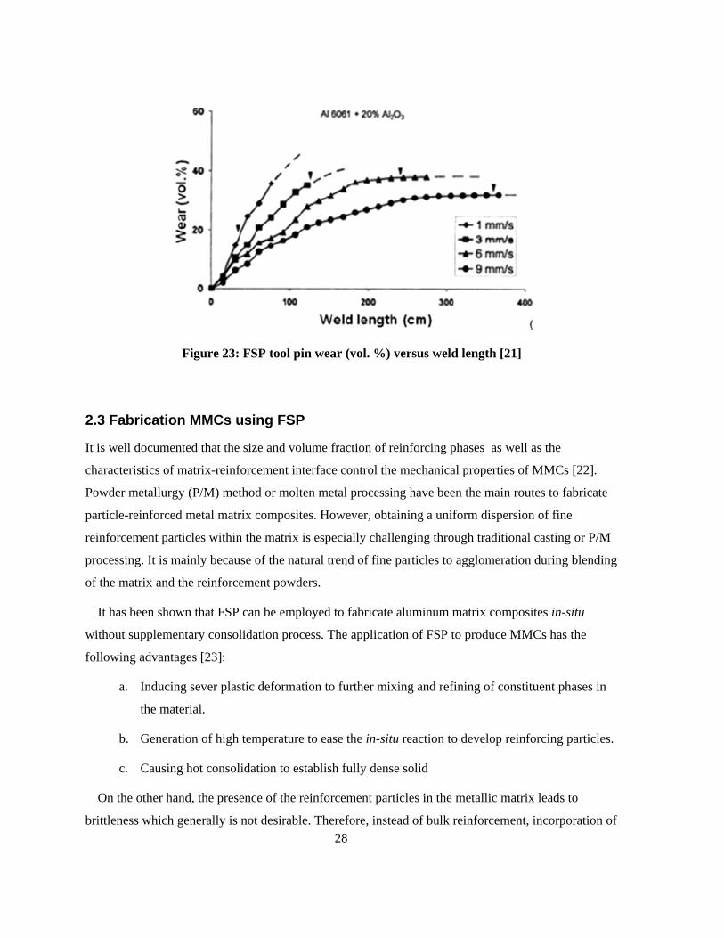
the tool consumption even for MMCs. Figure 23 shows the tool wear as a function of weld length for
different travel speeds. Thus, perception and designing the material flow around the pin profile in
solid state is extremely critical to extend the tool life and improve the process quality.
28
Figure 23: FSP tool pin wear (vol. %) versus weld length [21]
2.3 Fabrication MMCs using FSP
It is well documented that the size and volume fraction of reinforcing phases as well as the
characteristics of matrix-reinforcement interface control the mechanical properties of MMCs [22].
Powder metallurgy (P/M) method or molten metal processing have been the main routes to fabricate
particle-reinforced metal matrix composites. However, obtaining a uniform dispersion of fine
reinforcement particles within the matrix is especially challenging through traditional casting or P/M
processing. It is mainly because of the natural trend of fine particles to agglomeration during blending
of the matrix and the reinforcement powders.
It has been shown that FSP can be employed to fabricate aluminum matrix composites in-situ
without supplementary consolidation process. The application of FSP to produce MMCs has the
following advantages [23]:
a. Inducing sever plastic deformation to further mixing and refining of constituent phases in
the material.
b. Generation of high temperature to ease the in-situ reaction to develop reinforcing particles.
c. Causing hot consolidation to establish fully dense solid
On the other hand, the presence of the reinforcement particles in the metallic matrix leads to
brittleness which generally is not desirable. Therefore, instead of bulk reinforcement, incorporation of
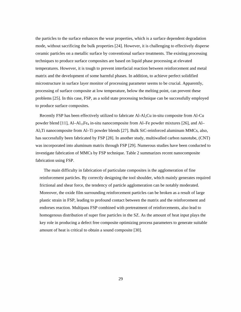
29
the particles to the surface enhances the wear properties, which is a surface dependent degradation
mode, without sacrificing the bulk properties [24]. However, it is challenging to effectively disperse
ceramic particles on a metallic surface by conventional surface treatments. The existing processing
techniques to produce surface composites are based on liquid phase processing at elevated
temperatures. However, it is tough to prevent interfacial reaction between reinforcement and metal
matrix and the development of some harmful phases. In addition, to achieve perfect solidified
microstructure in surface layer monitor of processing parameter seems to be crucial. Apparently,
processing of surface composite at low temperature, below the melting point, can prevent these
problems [25]. In this case, FSP, as a solid state processing technique can be successfully employed
to produce surface composites.
Recently FSP has been effectively utilized to fabricate Al-Al2Cu in-situ composite from Al-Cu
powder blend [11], Al–Al13Fe4 in-situ nanocomposite from Al–Fe powder mixtures [26], and Al–
Al3Ti nanocomposite from Al–Ti powder blends [27]. Bulk SiC-reinforced aluminum MMCs, also,
has successfully been fabricated by FSP [28]. In another study, multiwalled carbon nanotube, (CNT)
was incorporated into aluminum matrix through FSP [29]. Numerous studies have been conducted to
investigate fabrication of MMCs by FSP technique. Table 2 summarizes recent nanocomposite
fabrication using FSP.
The main difficulty in fabrication of particulate composites is the agglomeration of fine
reinforcement particles. By correctly designing the tool shoulder, which mainly generates required
frictional and shear force, the tendency of particle agglomeration can be notably moderated.
Moreover, the oxide film surrounding reinforcement particles can be broken as a result of large
plastic strain in FSP, leading to profound contact between the matrix and the reinforcement and
endorses reaction. Multipass FSP combined with pretreatment of reinforcements, also lead to
homogenous distribution of super fine particles in the SZ. As the amount of heat input plays the
key role in producing a defect free composite optimizing process parameters to generate suitable
amount of heat is critical to obtain a sound composite [30].
30
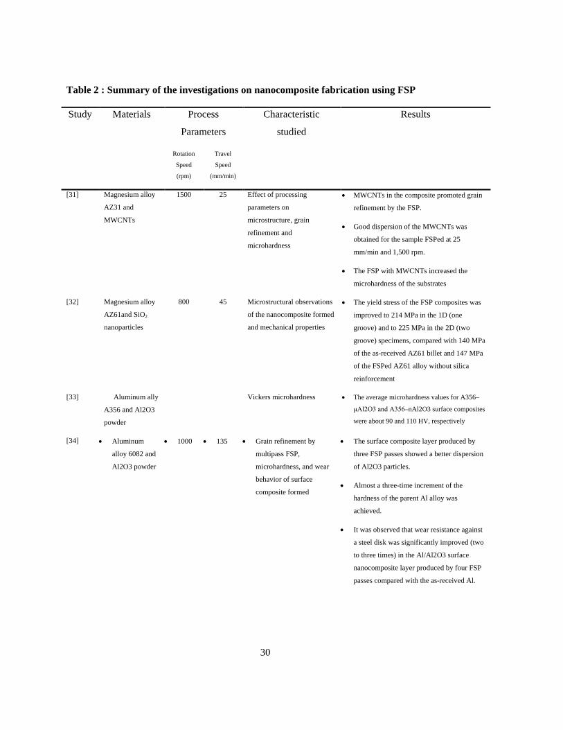
Table 2 : Summary of the investigations on nanocomposite fabrication using FSP
Study Materials Process
Parameters
Characteristic
studied
Results
Rotation
Speed
(rpm)
Travel
Speed
(mm/min)
[31] Magnesium alloy
AZ31 and
MWCNTs
1500 25 Effect of processing
parameters on
microstructure, grain
refinement and
microhardness
• MWCNTs in the composite promoted grain
refinement by the FSP.
• Good dispersion of the MWCNTs was
obtained for the sample FSPed at 25
mm/min and 1,500 rpm.
• The FSP with MWCNTs increased the
microhardness of the substrates
[32] Magnesium alloy
AZ61and SiO2
nanoparticles
800 45 Microstructural observations
of the nanocomposite formed
and mechanical properties
• The yield stress of the FSP composites was
improved to 214 MPa in the 1D (one
groove) and to 225 MPa in the 2D (two
groove) specimens, compared with 140 MPa
of the as-received AZ61 billet and 147 MPa
of the FSPed AZ61 alloy without silica
reinforcement
[33] Aluminum ally
A356 and Al2O3
powder
Vickers microhardness • The average microhardness values for A356–
μAl2O3 and A356–nAl2O3 surface composites
were about 90 and 110 HV, respectively
[34] • Aluminum
alloy 6082 and
Al2O3 powder
• 1000 • 135 • Grain refinement by
multipass FSP,
microhardness, and wear
behavior of surface
composite formed
• The surface composite layer produced by
three FSP passes showed a better dispersion
of Al2O3 particles.
• Almost a three-time increment of the
hardness of the parent Al alloy was
achieved.
• It was observed that wear resistance against
a steel disk was significantly improved (two
to three times) in the Al/Al2O3 surface
nanocomposite layer produced by four FSP
passes compared with the as-received Al.
31
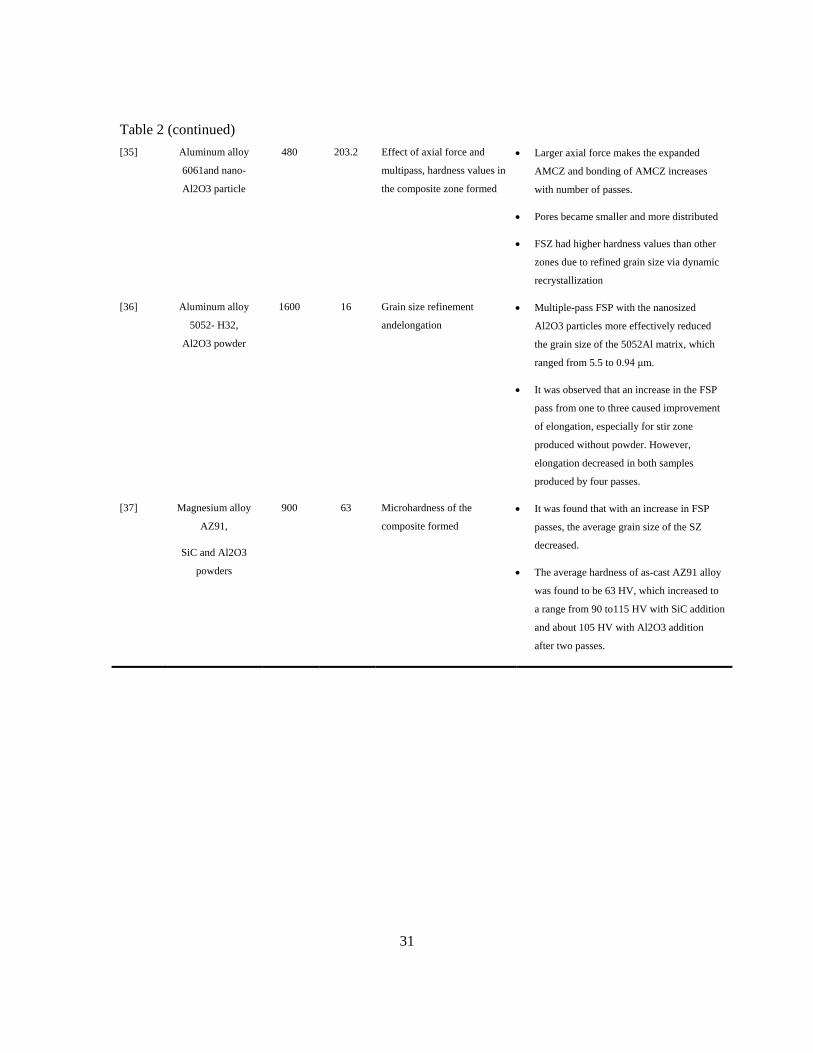
Table 2 (continued) [35] Aluminum alloy
6061and nano-
Al2O3 particle
480 203.2 Effect of axial force and
multipass, hardness values in
the composite zone formed
• Larger axial force makes the expanded
AMCZ and bonding of AMCZ increases
with number of passes.
• Pores became smaller and more distributed
• FSZ had higher hardness values than other
zones due to refined grain size via dynamic
recrystallization
[36] Aluminum alloy
5052- H32,
Al2O3 powder
1600 16 Grain size refinement
andelongation
• Multiple-pass FSP with the nanosized
Al2O3 particles more effectively reduced
the grain size of the 5052Al matrix, which
ranged from 5.5 to 0.94 μm.
• It was observed that an increase in the FSP
pass from one to three caused improvement
of elongation, especially for stir zone
produced without powder. However,
elongation decreased in both samples
produced by four passes.
[37] Magnesium alloy
AZ91,
SiC and Al2O3
powders
900 63 Microhardness of the
composite formed
• It was found that with an increase in FSP
passes, the average grain size of the SZ
decreased.
• The average hardness of as-cast AZ91 alloy
was found to be 63 HV, which increased to
a range from 90 to115 HV with SiC addition
and about 105 HV with Al2O3 addition
after two passes.
32
Chapter 3 Experimental Approaches
The as-received matrix material was 6.3 mm thick Al 5059 alloy in the rolled and H131 tempered
condition. Al 5059 is a non-heat treatable aluminum alloy and therefore consequent softening in the
heat affected zone is not expected after FSP. The nominal composition of Al 5059 is shown in Table
3.
Table 3: Nominal composition of Al 5059
Element Mg Mn Zn Fe Si Ti Zr
Wt.% 5.26 0.79 0.5 0.09 0.07 0.02 0.12
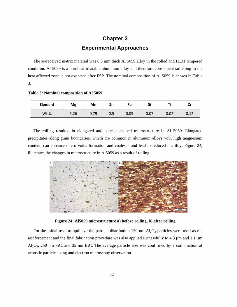
The rolling resulted in elongated and pancake-shaped microstructure in Al 5059. Elongated
precipitates along grain boundaries, which are common in aluminum alloys with high magnesium
content, can enhance micro voids formation and coalesce and lead to reduced ductility. Figure 24,
illustrates the changes in microstructure in Al5059 as a result of rolling.
Figure 24: Al5059 microstructure a) before rolling, b) after rolling
For the initial tests to optimize the particle distribution 130 nm Al2O3 particles were used as the
reinforcement and the final fabrication procedure was also applied successfully to 4.3 µm and 1.1 µm
Al2O3, 250 nm SiC, and 35 nm B4C. The average particle size was confirmed by a combination of
acoustic particle sizing and electron microscopy observation.
33
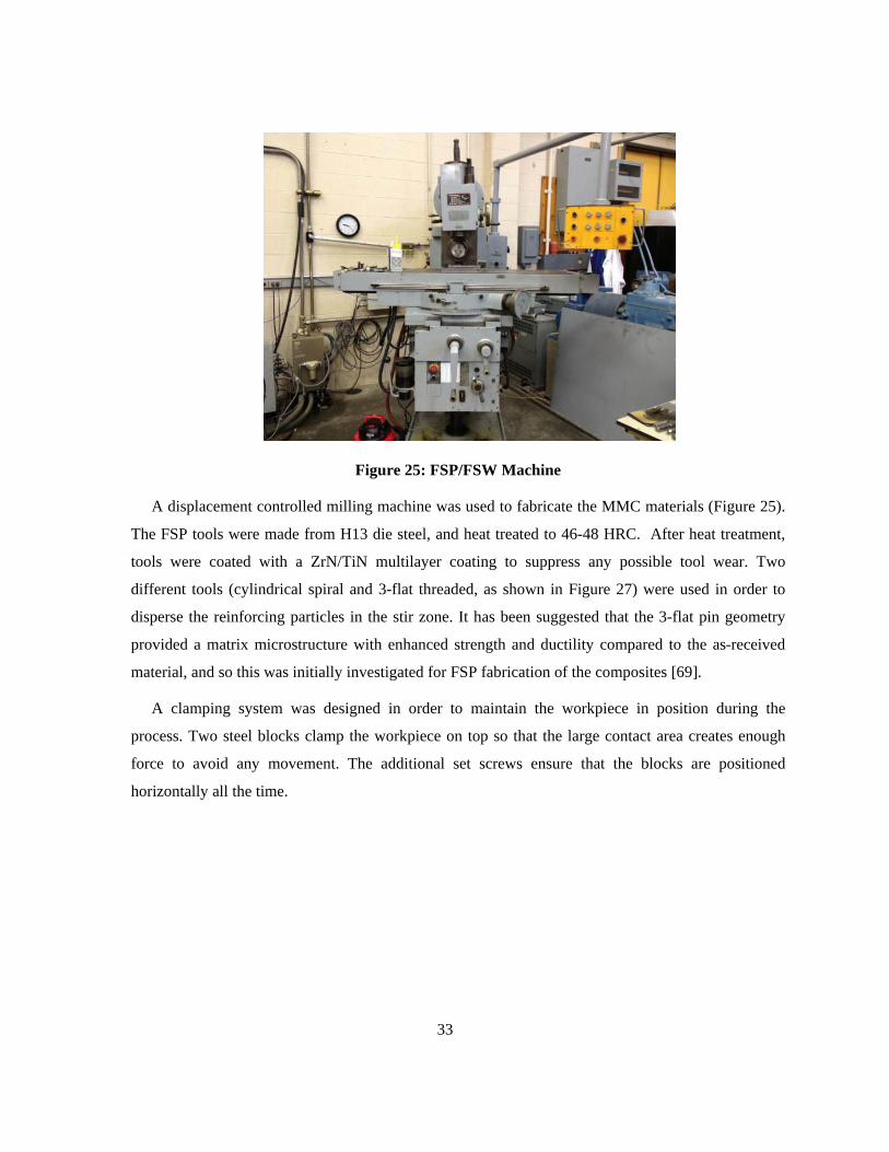
Figure 25: FSP/FSW Machine
A displacement controlled milling machine was used to fabricate the MMC materials (Figure 25).
The FSP tools were made from H13 die steel, and heat treated to 46-48 HRC. After heat treatment,
tools were coated with a ZrN/TiN multilayer coating to suppress any possible tool wear. Two
different tools (cylindrical spiral and 3-flat threaded, as shown in Figure 27) were used in order to
disperse the reinforcing particles in the stir zone. It has been suggested that the 3-flat pin geometry
provided a matrix microstructure with enhanced strength and ductility compared to the as-received
material, and so this was initially investigated for FSP fabrication of the composites [69].
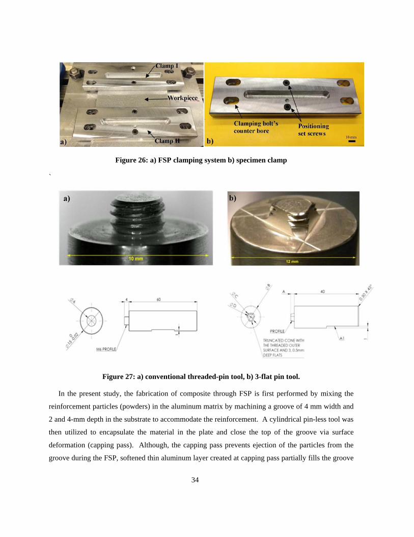
A clamping system was designed in order to maintain the workpiece in position during the
process. Two steel blocks clamp the workpiece on top so that the large contact area creates enough
force to avoid any movement. The additional set screws ensure that the blocks are positioned
horizontally all the time.
34
Figure 26: a) FSP clamping system b) specimen clamp
`
Figure 27: a) conventional threaded-pin tool, b) 3-flat pin tool.
In the present study, the fabrication of composite through FSP is first performed by mixing the
reinforcement particles (powders) in the aluminum matrix by machining a groove of 4 mm width and
2 and 4-mm depth in the substrate to accommodate the reinforcement. A cylindrical pin-less tool was
then utilized to encapsulate the material in the plate and close the top of the groove via surface
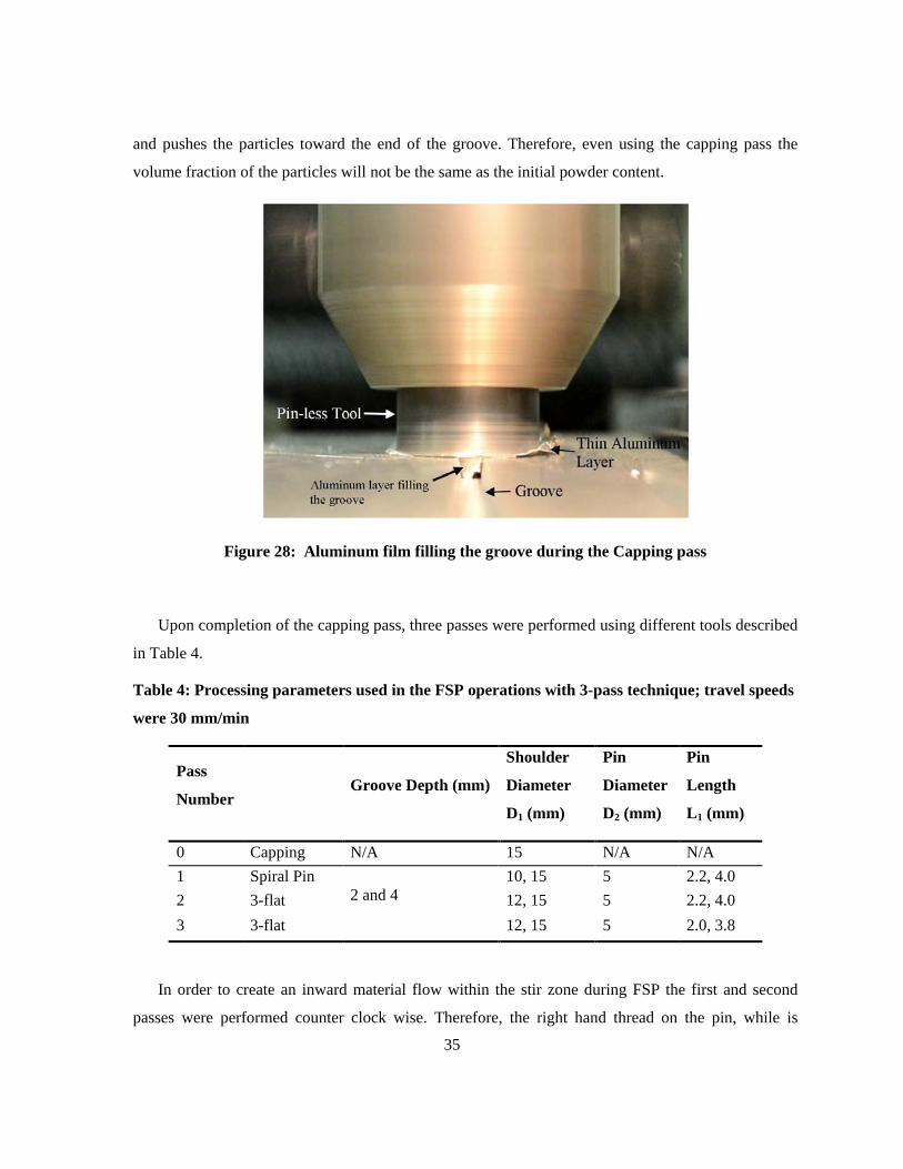
deformation (capping pass). Although, the capping pass prevents ejection of the particles from the
groove during the FSP, softened thin aluminum layer created at capping pass partially fills the groove
35
and pushes the particles toward the end of the groove. Therefore, even using the capping pass the
volume fraction of the particles will not be the same as the initial powder content.
Figure 28: Aluminum film filling the groove during the Capping pass
Upon completion of the capping pass, three passes were performed using different tools described
in Table 4.
Table 4: Processing parameters used in the FSP operations with 3-pass technique; travel speeds
were 30 mm/min
Pass
Number Groove Depth (mm)
Shoulder
Diameter
D1 (mm)
Pin
Diameter
D2 (mm)
Pin
Length
L1 (mm)
0 Capping N/A 15 N/A N/A 1 Spiral Pin
2 and 4 10, 15 5 2.2, 4.0
2 3-flat 12, 15 5 2.2, 4.0 3 3-flat 12, 15 5 2.0, 3.8
In order to create an inward material flow within the stir zone during FSP the first and second
passes were performed counter clock wise. Therefore, the right hand thread on the pin, while is
36
rotating CCW, pushes the particles toward the bottom of the stir zone. The third pass, however, was
carried out with clock-wise tool rotation to promote movement of the material from bottom of the stir
zone toward the surface, resulting in improved vertical uniformity. Process parameters are
summarized in Table 5.
Table 5: Summary of FSP Parameters applied
Pass
Number Tool RPM Rotation Direction
Inclination ( ◦ )
Travel Speed (mm/min)
0 Capping Capping 1800 CW
30 1 Pass 1 Spiral pin 1120 CCW 2.5 2 Pass 2 3 flat 450 CCW 2.5 3 Pass 3 3 flat 450 CW 2.5
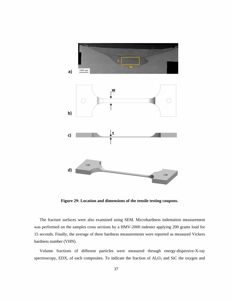
In order to study the mechanical properties of the composites, uniaxial tensile testing was
performed at a constant strain rate of 10-3 sec-1 by using a Tinius Olsen (H10KT) tensile testing
machine. To achieve maximum uniformity, the tensile coupons were machined such that the gauge
length of 12.5 mm consisted of only the uniformly distributed regions in the composite material
extracted from the stir zone with dimensions of t and w between 1 to 4 mm (see Figure 29). An
extensometer was used to measure the engineering strain. In tensile tests, consistent and repetitive
results were obtained with standard deviations between samples processed in comparable fashion
were less than 5% (minimum 3 samples per condition).
37
Figure 29: Location and dimensions of the tensile testing coupons.
The fracture surfaces were also examined using SEM. Microhardness indentation measurement
was performed on the samples cross sections by a HMV-2000 indenter applying 200 grams load for
15 seconds. Finally, the average of three hardness measurements were reported as measured Vickers
hardness number (VHN).
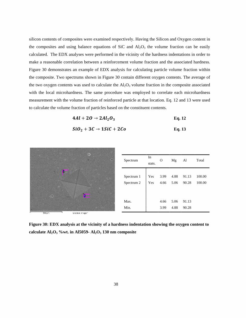
Volume fractions of different particles were measured through energy-dispersive-X-ray
spectroscopy, EDX, of each composites. To indicate the fraction of Al2O3 and SiC the oxygen and
38
silicon contents of composites were examined respectively. Having the Silicon and Oxygen content in
the composites and using balance equations of SiC and Al2O3 the volume fraction can be easily
calculated. The EDX analyses were performed in the vicinity of the hardness indentations in order to
make a reasonable correlation between a reinforcement volume fraction and the associated hardness.
Figure 30 demonstrates an example of EDX analysis for calculating particle volume fraction within
the composite. Two spectrums shown in Figure 30 contain different oxygen contents. The average of
the two oxygen contents was used to calculate the Al2O3 volume fraction in the composite associated
with the local microhardness. The same procedure was employed to correlate each microhardness
measurement with the volume fraction of reinforced particle at that location. Eq. 12 and 13 were used
to calculate the volume fraction of particles based on the constituent contents.
𝟒𝑨𝒍 + 𝟐𝑶 → 𝟐𝑨𝒍𝟐𝑶𝟑 Eq. 12
𝑺𝒊𝑶𝟐 + 𝟑𝑪 → 𝟏𝑺𝒊𝑪 + 𝟐𝑪𝒐 Eq. 13
Spectrum In
stats. O Mg Al Total
Spectrum 1 Yes 3.99 4.88 91.13 100.00
Spectrum 2 Yes 4.66 5.06 90.28 100.00
Max. 4.66 5.06 91.13
Min. 3.99 4.88 90.28
Figure 30: EDX analysis at the vicinity of a hardness indentation showing the oxygen content to
calculate Al2O3 %wt. in Al5059- Al2O3 130 nm composite
39
Chapter 4 Results and Discussion
4.1 Particle distribution
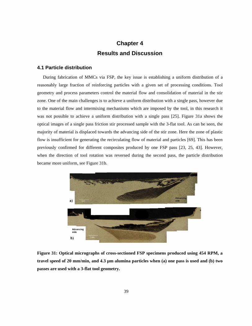
During fabrication of MMCs via FSP, the key issue is establishing a uniform distribution of a
reasonably large fraction of reinforcing particles with a given set of processing conditions. Tool
geometry and process parameters control the material flow and consolidation of material in the stir
zone. One of the main challenges is to achieve a uniform distribution with a single pass, however due
to the material flow and intermixing mechanisms which are imposed by the tool, in this research it
was not possible to achieve a uniform distribution with a single pass [25]. Figure 31a shows the
optical images of a single pass friction stir processed sample with the 3-flat tool. As can be seen, the
majority of material is displaced towards the advancing side of the stir zone. Here the zone of plastic
flow is insufficient for generating the recirculating flow of material and particles [69]. This has been
previously confirmed for different composites produced by one FSP pass [23, 25, 43]. However,
when the direction of tool rotation was reversed during the second pass, the particle distribution
became more uniform, see Figure 31b.
Figure 31: Optical micrographs of cross-sectioned FSP specimens produced using 454 RPM, a
travel speed of 20 mm/min, and 4.3 µm alumina particles when (a) one pass is used and (b) two
passes are used with a 3-flat tool geometry.
40
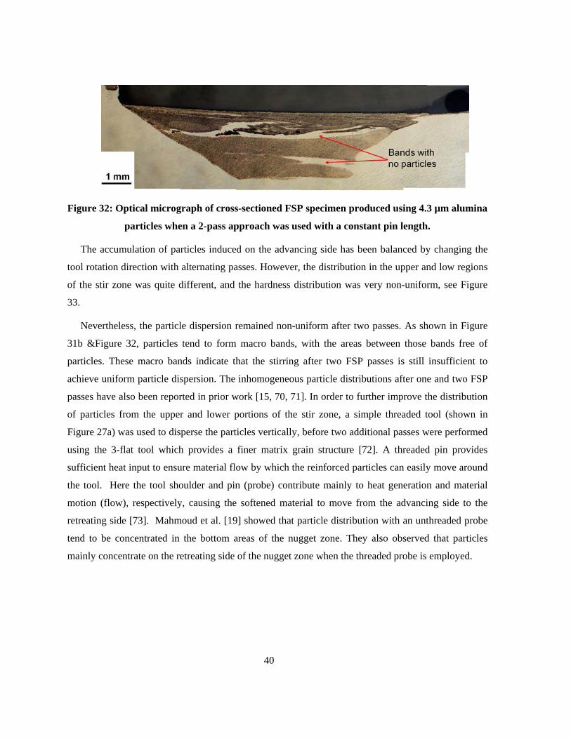
Figure 32: Optical micrograph of cross-sectioned FSP specimen produced using 4.3 µm alumina
particles when a 2-pass approach was used with a constant pin length.
The accumulation of particles induced on the advancing side has been balanced by changing the
tool rotation direction with alternating passes. However, the distribution in the upper and low regions
of the stir zone was quite different, and the hardness distribution was very non-uniform, see Figure
33.
Nevertheless, the particle dispersion remained non-uniform after two passes. As shown in Figure
31b &Figure 32, particles tend to form macro bands, with the areas between those bands free of
particles. These macro bands indicate that the stirring after two FSP passes is still insufficient to
achieve uniform particle dispersion. The inhomogeneous particle distributions after one and two FSP
passes have also been reported in prior work [15, 70, 71]. In order to further improve the distribution
of particles from the upper and lower portions of the stir zone, a simple threaded tool (shown in
Figure 27a) was used to disperse the particles vertically, before two additional passes were performed
using the 3-flat tool which provides a finer matrix grain structure [72]. A threaded pin provides
sufficient heat input to ensure material flow by which the reinforced particles can easily move around
the tool. Here the tool shoulder and pin (probe) contribute mainly to heat generation and material
motion (flow), respectively, causing the softened material to move from the advancing side to the
retreating side [73]. Mahmoud et al. [19] showed that particle distribution with an unthreaded probe
tend to be concentrated in the bottom areas of the nugget zone. They also observed that particles
mainly concentrate on the retreating side of the nugget zone when the threaded probe is employed.
41
Figure 33: Optical micrograph of cross-sectioned FSP specimen produced using 130 nm
alumina particles when a 3-pass approach was used with the parameters described in Table 1
using a 2.2 mm pin and 10 mm shoulder tool for the first and second passes and a 2 mm 3-flat
pin for the third pass
Figure 34: Microhardness profile along stir zone when FSP procedure is conducted in 1 to 3
passes with the parameters indicated in Table 1, and a 1.2 mm deep groove, as well as when 3
passes are used with a 2.0 mm groove.
30
50
70
90
110
130
-6 -4 -2 0 2 4 6
Mic
roha
rdne
ss, H
V
Position from centerline, mm
3 Pass
2 Pass
1 pass
42
When the three-pass process was applied, the distribution of reinforcing particles was much more
uniform in the upper and lower portions of the stir zone, as shown in Figure 33. This is in agreement
with Mahmoud et al. [19] findings on the fabrication of SiC particle reinforced aluminum matrix
composites through FSP. These are expected to result from the incorporation of the aluminum alloy
material on the outer boundary of the stir zone due to the recirculating flow produced by the tool
during the final pass. This recirculating flow has been studied in a number of prior studies (for
example see [74]).The incorporation of the aluminum alloy material arises from penetration of the
tool into the unreinforced matrix material during the final pass. This penetration of the tool occurs as
a result of the thermal softening of the material during FSP, and is inevitable since sufficient axial
force must be applied in order to prevent formation of voids and defects within the stir zone and
achieve uniform particle distribution. In order to avoid incorporating unreinforced aluminum alloy
material into the stir zone during the final pass, a 3-flat tool with a slightly shorter pin (2.0 mm rather
than 2.2 mm) was used for the third pass. This ensured that when the tool penetrates into the plate, the
pin will not mix new material from below the FSP zone into the stir zone. This method allowed a stir
zone with a uniform distribution of particles to be produced, with both micro-scale and nano-scale
reinforcing particles. Figure 33 shows an optical micrograph of the composite fabricated with the
conditions shown in Table 4 and 5 where alumina nanoparticles were used as the reinforcement and
the final pass conducted with the slightly shorter pin. As can be seen a uniform distribution of
particles is achieved in the stir zone. Based on these results, it is apparent that the dispersion
condition could be controlled by the number of passes and the geometry/position of the tool.
4.2 Mechanical testing and fractography
Figure 34 shows Vickers hardness versus position when using different FSP passes. It can be
noted that following the first pass, the fluctuation in the hardness is very significant which is due to
non-uniform/incomplete mixing of materials and presence of voids in the stir zone. However, with
increasing number of passes, the hardness distribution becomes more uniform, where the average
hardness increases from 84±3 HV in the base metal to 100±2 HV in the stir zone. This strengthening
can be attributed to grain refinement and uniform distribution of the particles imposed by FSP.
However we have shown elsewhere that the contribution of grain refinement is not significant, so
secondary particle strengthening is likely to be the main factor here. Although distribution of particles
in the 3-pass FSP is more homogenous, this does not necessarily raise the hardness as compared with
2-pass FSP presumably due to the agglomeration of particles. Figure 34 also shows hardness values
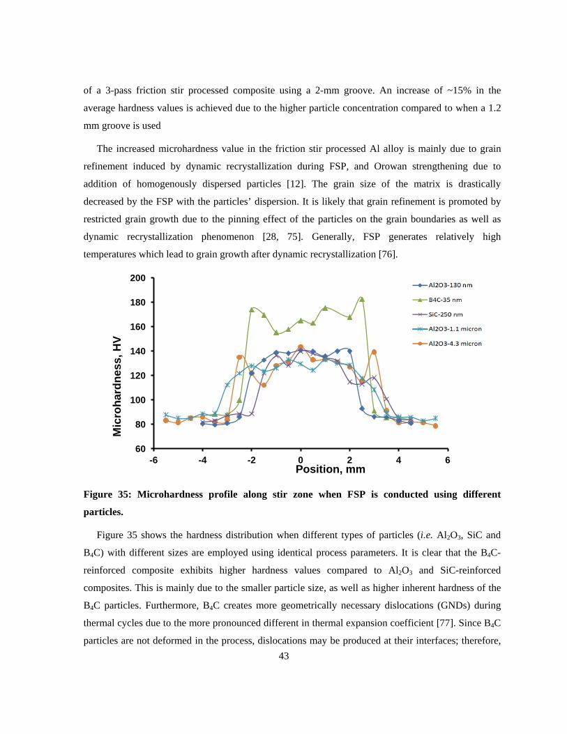
43
of a 3-pass friction stir processed composite using a 2-mm groove. An increase of ~15% in the
average hardness values is achieved due to the higher particle concentration compared to when a 1.2
mm groove is used
The increased microhardness value in the friction stir processed Al alloy is mainly due to grain
refinement induced by dynamic recrystallization during FSP, and Orowan strengthening due to
addition of homogenously dispersed particles [12]. The grain size of the matrix is drastically
decreased by the FSP with the particles’ dispersion. It is likely that grain refinement is promoted by
restricted grain growth due to the pinning effect of the particles on the grain boundaries as well as
dynamic recrystallization phenomenon [28, 75]. Generally, FSP generates relatively high
temperatures which lead to grain growth after dynamic recrystallization [76].
Figure 35: Microhardness profile along stir zone when FSP is conducted using different
particles.
Figure 35 shows the hardness distribution when different types of particles (i.e. Al2O3, SiC and
B4C) with different sizes are employed using identical process parameters. It is clear that the B4C-
reinforced composite exhibits higher hardness values compared to Al2O3 and SiC-reinforced
composites. This is mainly due to the smaller particle size, as well as higher inherent hardness of the
B4C particles. Furthermore, B4C creates more geometrically necessary dislocations (GNDs) during
thermal cycles due to the more pronounced different in thermal expansion coefficient [77]. Since B4C
particles are not deformed in the process, dislocations may be produced at their interfaces; therefore,
60
80
100
120
140
160
180
200
-6 -4 -2 0 2 4 6
Mic
roha
rdne
ss, H
V
Position, mm
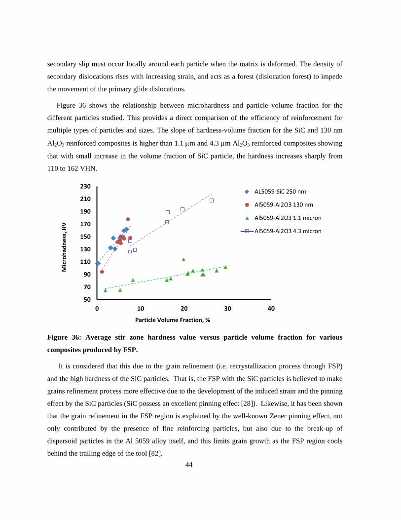
44
secondary slip must occur locally around each particle when the matrix is deformed. The density of
secondary dislocations rises with increasing strain, and acts as a forest (dislocation forest) to impede
the movement of the primary glide dislocations.
Figure 36 shows the relationship between microhardness and particle volume fraction for the
different particles studied. This provides a direct comparison of the efficiency of reinforcement for
multiple types of particles and sizes. The slope of hardness-volume fraction for the SiC and 130 nm
Al2O3 reinforced composites is higher than 1.1 µm and 4.3 µm Al2O3 reinforced composites showing
that with small increase in the volume fraction of SiC particle, the hardness increases sharply from
110 to 162 VHN.
Figure 36: Average stir zone hardness value versus particle volume fraction for various
composites produced by FSP.
It is considered that this due to the grain refinement (i.e. recrystallization process through FSP)
and the high hardness of the SiC particles. That is, the FSP with the SiC particles is believed to make
grains refinement process more effective due to the development of the induced strain and the pinning
effect by the SiC particles (SiC possess an excellent pinning effect [28]). Likewise, it has been shown
that the grain refinement in the FSP region is explained by the well-known Zener pinning effect, not
only contributed by the presence of fine reinforcing particles, but also due to the break-up of
dispersoid particles in the Al 5059 alloy itself, and this limits grain growth as the FSP region cools
behind the trailing edge of the tool [82].
50
70
90
110
130
150
170
190
210
230
0 10 20 30 40
Mic
roha
dnes
s, H
V
Particle Volume Fraction, %
AL5059-SiC 250 nm
Al5059-Al2O3 130 nm
Al5059-Al2O3 1.1 micron
Al5059-Al2O3 4.3 micron
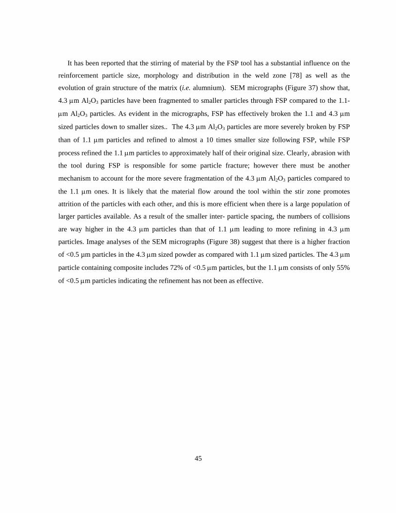
45
It has been reported that the stirring of material by the FSP tool has a substantial influence on the
reinforcement particle size, morphology and distribution in the weld zone [78] as well as the
evolution of grain structure of the matrix (i.e. alumnium). SEM micrographs (Figure 37) show that,
4.3 µm Al2O3 particles have been fragmented to smaller particles through FSP compared to the 1.1-
µm Al2O3 particles. As evident in the micrographs, FSP has effectively broken the 1.1 and 4.3 µm
sized particles down to smaller sizes.. The 4.3 µm Al2O3 particles are more severely broken by FSP
than of 1.1 µm particles and refined to almost a 10 times smaller size following FSP, while FSP
process refined the 1.1 µm particles to approximately half of their original size. Clearly, abrasion with
the tool during FSP is responsible for some particle fracture; however there must be another
mechanism to account for the more severe fragmentation of the 4.3 µm Al2O3 particles compared to
the 1.1 µm ones. It is likely that the material flow around the tool within the stir zone promotes
attrition of the particles with each other, and this is more efficient when there is a large population of
larger particles available. As a result of the smaller inter- particle spacing, the numbers of collisions
are way higher in the 4.3 µm particles than that of 1.1 µm leading to more refining in 4.3 µm
particles. Image analyses of the SEM micrographs (Figure 38) suggest that there is a higher fraction
of <0.5 µm particles in the 4.3 µm sized powder as compared with 1.1 µm sized particles. The 4.3 µm
particle containing composite includes 72% of <0.5 µm particles, but the 1.1 µm consists of only 55%
of <0.5 µm particles indicating the refinement has not been as effective.
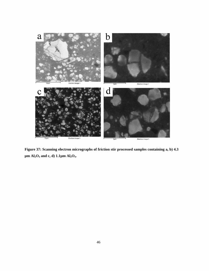
46
Figure 37: Scanning electron micrographs of friction stir processed samples containing a, b) 4.3
µm Al2O3 and c, d) 1.1µm Al2O3.
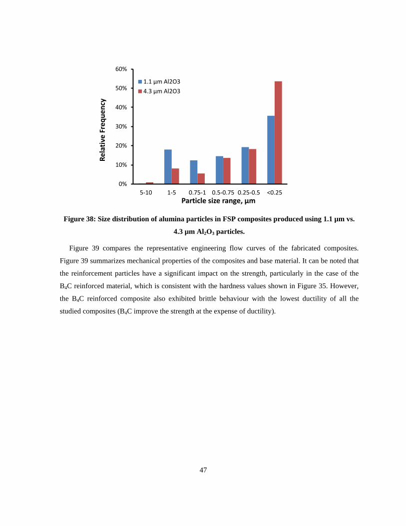
47
Figure 38: Size distribution of alumina particles in FSP composites produced using 1.1 µm vs.
4.3 µm Al2O3 particles.
Figure 39 compares the representative engineering flow curves of the fabricated composites.
Figure 39 summarizes mechanical properties of the composites and base material. It can be noted that
the reinforcement particles have a significant impact on the strength, particularly in the case of the
B4C reinforced material, which is consistent with the hardness values shown in Figure 35. However,
the B4C reinforced composite also exhibited brittle behaviour with the lowest ductility of all the
studied composites (B4C improve the strength at the expense of ductility).
0%
10%
20%
30%
40%
50%
60%
5-10 1-5 0.75-1 0.5-0.75 0.25-0.5 <0.25
Rela
tive
Freq
uenc
y
Particle size range, µm
1.1 µm Al2O3 4.3 µm Al2O3
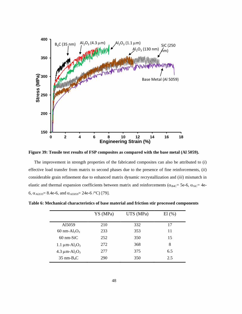
48
Figure 39: Tensile test results of FSP composites as compared with the base metal (Al 5059).
The improvement in strength properties of the fabricated composites can also be attributed to (i)
effective load transfer from matrix to second phases due to the presence of fine reinforcements, (ii)
considerable grain refinement due to enhanced matrix dynamic recrystallization and (iii) mismatch in
elastic and thermal expansion coefficients between matrix and reinforcements (αB4C= 5e-6, αSiC= 4e-
6, αAl2O3= 8.4e-6, and αAl5059= 24e-6 /°C) [79].
Table 6: Mechanical characteristics of base material and friction stir processed components
YS (MPa) UTS (MPa) El (%)
Al5059 210 332 17 60 nm-Al2O3 233 353 11 60 nm-SiC 252 350 15
1.1 µm-Al2O3 272 368 8 4.3 µm-Al2O3 277 375 6.5
35 nm-B4C 290 350 2.5
150
200
250
300
350
400
0 2 4 6 8 10 12 14 16 18
Stre
ss (M
Pa)
Engineering Strain (%)
B4C (35 nm) Al2O3 (4.3 µm) Al2O3 (1.1 µm)
SiC (250 nm) Al2O3 (130 nm)
Base Metal (Al 5059)

49
As is seen in Figure 40 pronounced strain hardening behavior is observed in the FSP Al-based
composites as compared with base metal. If one ranks the materials from the highest to lowest
hardening rate (y-axis), the B4C is highest, yet it has the lowest strain. We would expect that the high
strain hardening rate would suppress the fracture; however this may not have been accomplished for
B4C, since we also see the fracture surfaces are rather flat with little evidence of plastic deformation
or strain accommodation just before fracture. The work hardening rate in Al2O3 130 nm and 1.1 µm
are higher than the base metal which is in agreement with the results of Hu et al. [80]. These particles
promote the pinning of active dislocations and grain boundaries of recrystallized grains. That is,
uniformly distributed second particles in the friction stir processed samples can create, drag and hold
(pin) dislocations causing dynamic recovery to be postponed.
The SiC is changing the hardening rate over the strains and the ranking is changing. It has been
showed that the stress concentration around inclusions lead to embrittlement when a critical size was
reached around 400 nm [81]. The 130 nm and 1.1 µm actually had final particle sizes both <300 nm
it seems based on the SEM results, so it may be consistent with this stress concentration issue which
promotes void nucleation. The Al2O3-4.3 µm shows a low work hardening rate because the large
particles most likely promote void nucleation and de-cohesion before strain hardening can become
active.
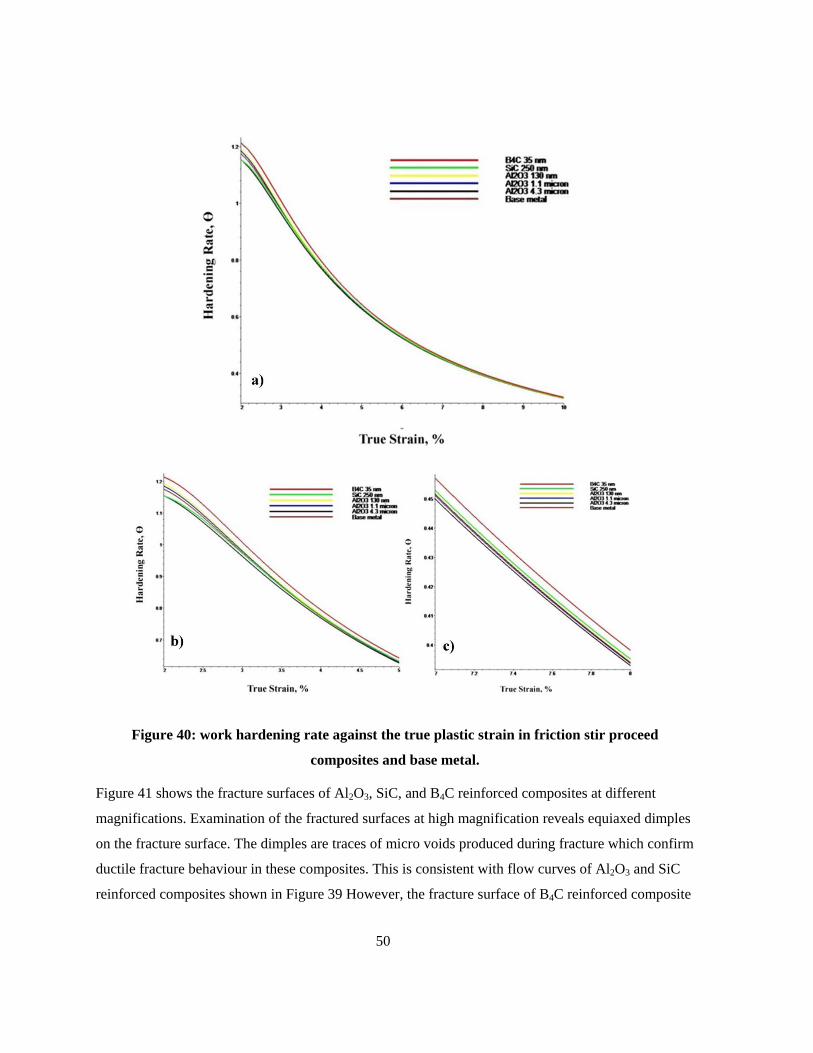
50
Figure 40: work hardening rate against the true plastic strain in friction stir proceed
composites and base metal.
Figure 41 shows the fracture surfaces of Al2O3, SiC, and B4C reinforced composites at different
magnifications. Examination of the fractured surfaces at high magnification reveals equiaxed dimples
on the fracture surface. The dimples are traces of micro voids produced during fracture which confirm
ductile fracture behaviour in these composites. This is consistent with flow curves of Al2O3 and SiC
reinforced composites shown in Figure 39 However, the fracture surface of B4C reinforced composite
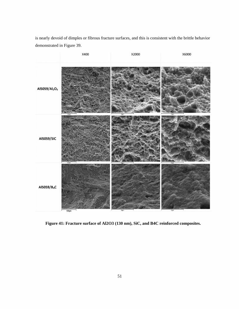
51
is nearly devoid of dimples or fibrous fracture surfaces, and this is consistent with the brittle behavior
demonstrated in Figure 39.
Figure 41: Fracture surface of Al2O3 (130 nm), SiC, and B4C reinforced composites.
52
Chapter 5 Conclusions
Metal matrix composites were successfully produced using friction stir processing by incorporating
various reinforcement particles in different sizes. The influence of particle type and size distribution
was studied in Al-alloy metal matrix composites produce by FSP. The mechanical and fracture
behaviour was compared between the composites, and the main findings were that:
• By increasing the number of FSP passes, the distribution of reinforcing particles was much
more homogeneous in the upper and lower portions of the stir zone.
• 3-pass friction stir processed composites made using a 2-mm groove and reinforced by
particles shows an increase of ~15% in the hardness profile as compared with friction stir
processed composite with no particles. This clearly confirms the effect of particles inclusion
on the hardness profile.
• B4C-reinforced composites exhibit the highest tensile yield strength; however their ductility is
drastically reduced to 2.5% elongation in comparison to base metal.
• When using 4.3-µm Al2O3 particles, the FSP technique results in a 10 times refinement in the
particle, while 1.1-µm Al2O3 particles are only refined to approximately half of their original
size due to the less effective attrition within the severely deformed stir zone.
• The fracture surfaces confirm ductile fracture in the Al2O3-, SiC-reinforced composites and brittle fracture in the B4C-reinforced composite, consistent with observed tensile flow curves.
53
Bibliography
[1] A. H. Feng and Z. Y. Ma, "Enhanced mechanical properties of Mg-Al-Zn cast alloy via
friction stir processing," Scripta Materialia, vol. 56, pp. 397-400, 2007. [2] W. M. Thomas, E. D. Nicholas, J. D. Needham, M. G. Murch, P. Templesmith, and C. J.
Daws, 1991. [3] R. S. Mishra and Z. Y. Ma, "Friction stir welding and processing," Materials Science and
Engineering R: Reports, vol. 50, 2005. [4] H. S. Arora, H. Singh, and B. K. Dhindaw, "Some observations on microstructural changes in
a Mg-based AE42 alloy subjected to friction stir processing," Metallurgical and Materials Transactions B: Process Metallurgy and Materials Processing Science, vol. 43, pp. 92-108, 2012.
[5] P. Cavaliere and P. P. De Marco, "Friction stir processing of AM60B magnesium alloy sheets," Materials Science and Engineering A, vol. 462, pp. 393-397, 2007.
[6] C. B. Fuller and M. W. Mahoney, "The effect of friction stir processing on 5083-H321/5356 Al arc welds: Microstructural and mechanical analysis," Metallurgical and Materials Transactions A: Physical Metallurgy and Materials Science, vol. 37, pp. 3605-3615, 2006.
[7] M. D. Fuller, S. Swaminathan, A. P. Zhilyaev, and T. R. McNelley, "Microstructural transformations and mechanical properties of cast NiAl bronze: Effects of fusion welding and friction stir processing," Materials Science and Engineering A, vol. 463, pp. 128-137, 2007.
[8] K. Oh-Ishi and T. R. McNelley, "Microstructural modification of as-cast NiAl bronze by friction stir processing," Metallurgical and Materials Transactions A: Physical Metallurgy and Materials Science, vol. 35 A, pp. 2951-2961, 2004.
[9] M. Tsujikawa, S. W. Chung, M. Tanaka, Y. Takigawa, S. Oki, and K. Higashi, "High-strengthening of Mg - 5.5 mass % Y-4.3 mass % Zn cast alloy by friction stir processing," Materials Transactions, vol. 46, pp. 3081-3084, 2005.
[10] R. Bauri, D. Yadav, and G. Suhas, "Effect of friction stir processing (FSP) on microstructure and properties of Al-TiC in situ composite," Materials Science and Engineering A, vol. 528, pp. 4732-4739, 2011.
[11] P. B. Berbon, W. H. Bingel, R. S. Mishra, C. C. Bampton, and M. W. Mahoney, "Friction stir processing: A tool to homogenize nanocomposite aluminum alloys," Scripta Materialia, vol. 44, pp. 61-66, 2001.
[12] P. Cavaliere, "Mechanical properties of Friction Stir Processed 2618/Al2O3 metal matrix composite," Composites Part A: Applied Science and Manufacturing, vol. 36, pp. 1657-1665, 2005.
[13] K. J. Hodder, H. Izadi, A. G. McDonald, and A. P. Gerlich, "Fabrication of aluminum–alumina metal matrix composites via cold gas dynamic spraying at low pressure followed by friction stir processing," Materials Science and Engineering: A, vol. 556, pp. 114-121, 2012.
[14] Y. Morisada, H. Fujii, T. Mizuno, G. Abe, T. Nagaoka, and M. Fukusumi, "Modification of thermally sprayed cemented carbide layer by friction stir processing," Surface and Coatings Technology, vol. 204, pp. 2459-2464, 2010.
54
[15] Y. Morisada, H. Fujii, T. Nagaoka, and M. Fukusumi, "MWCNTs/AZ31 surface composites fabricated by friction stir processing," Materials Science and Engineering A, vol. 419, pp. 344-348, 2006.
[16] C. J. Lee, J. C. Huang, and P. J. Hsieh, "Mg based nano-composites fabricated by friction stir processing," Scripta Materialia, vol. 54, pp. 1415-1420, 2006.
[17] R. S. Mishra, Z. Y. Ma, and I. Charit, "Friction stir processing: A novel technique for fabrication of surface composite," Materials Science and Engineering A, vol. 341, pp. 307-310, 2003.
[18] P. Liu, Q. Shi, X. Bian, S. Xu, and G. Ren, "Microstructure of a novel Al-based amorphous reinforced aluminum metal matrix composite," Hanjie Xuebao/Transactions of the China Welding Institution, vol. 30, pp. 13-16, 2009.
[19] E. R. I. Mahmoud, M. Takahashi, T. Shibayanagi, and K. Ikeuchi, "Wear characteristics of surface-hybrid-MMCs layer fabricated on aluminum plate by friction stir processing," Wear, vol. 268, pp. 1111-1121, 2010.
[20] A. Tewari, J. E. Spowart, A. M. Gokhale, R. S. Mishra, and D. B. Miracle, "Characterization of the effects of friction stir processing on microstructural changes in DRA composites," Materials Science and Engineering A, vol. 428, pp. 80-90, 2006.
[21] W. Wang, Q. y. Shi, P. Liu, H. k. Li, and T. Li, "A novel way to produce bulk SiCp reinforced aluminum metal matrix composites by friction stir processing," Journal of Materials Processing Technology, vol. 209, pp. 2099-2103, 2009.
[22] A. Shafiei-Zarghani, S. F. Kashani-Bozorg, and A. Zarei-Hanzaki, "Microstructures and mechanical properties of Al/Al2O3 surface nano-composite layer produced by friction stir processing," Materials Science and Engineering A, vol. 500, pp. 84-91, 2009.
[23] M. Yang, C. Xu, C. Wu, K. C. Lin, Y. J. Chao, and L. An, "Fabrication of AA6061/Al2O3 nano ceramic particle reinforced composite coating by using friction stir processing," Journal of Materials Science, vol. 45, pp. 4431-4438, 2010.
[24] M. Dixit, J. W. Newkirk, and R. S. Mishra, "Properties of friction stir-processed Al 1100-NiTi composite," Scripta Materialia, vol. 56, pp. 541-544, 2007.
[25] D. K. Lim, T. Shibayanagi, and A. P. Gerlich, "Synthesis of multi-walled CNT reinforced aluminium alloy composite via friction stir processing," Materials Science and Engineering A, vol. 507, pp. 194-199, 2009.
[26] L. B. Johannes, L. L. Yowell, E. Sosa, S. Arepalli, and R. S. Mishra, "Survivability of single-walled carbon nanotubes during friction stir processing," Nanotechnology, vol. 17, pp. 3081-3084, 2006.
[27] H. Izadi and A. P. Gerlich, "Distribution and stability of carbon nanotubes during multi-pass friction stir processing of carbon nanotube/aluminum composites," Carbon, vol. 50, pp. 4744-4749, 2012.
[28] Y. Morisada, H. Fujii, T. Nagaoka, K. Nogi, and M. Fukusumi, "Fullerene/A5083 composites fabricated by material flow during friction stir processing," Composites Part A: Applied Science and Manufacturing, vol. 38, pp. 2097-2101, 2007.
[29] D. Yadav and R. Bauri, "Nickel particle embedded aluminium matrix composite with high ductility," Materials Letters, vol. 64, pp. 664-667, 2010.
[30] L. Zhang, R. Chandrasekar, J. Y. Howe, M. K. West, N. E. Hedin, W. J. Arbegast, et al., "A Metal Matrix Composite Prepared from Electrospun TiO2 Nanofibers and an Al 1100 Alloy via Friction Stir Processing," Applied Materials and Interfaces, vol. 1, pp. 987-991, 2009.
[31] C. I. Chang, Y. N. Wang, H. R. Pei, C. J. Lee, X. H. Du, and J. C. Huang, "Microstructure and Mechanical Properties of Nano-ZrO2 and Nano-SiO2 Particulate Reinforced AZ31-Mg
55
Based Composites Fabricated by Friction Stir Processing," Key Engineering Materials, vol. 351, pp. 114-119, 2007 2007.
[32] Y. Morisada, H. Fujii, T. Nagaoka, and M. Fukusumi, "Effect of friction stir processing with SiC particles on microstructure and hardness of AZ31," Materials Science and Engineering A, vol. 433, pp. 50-54, 2006.
[33] Y. Morisada, H. Fujii, T. Nagaoka, and M. Fukusumi, "Nanocrystallized magnesium alloy - uniform dispersion of C<sub>60</sub> molecules," Scripta Materialia, vol. 55, pp. 1067-1070, 2006.
[34] M. Barmouz, M. K. Besharati Givi, and J. Seyfi, "On the role of processing parameters in producing Cu/SiC metal matrix composites via friction stir processing: Investigating microstructure, microhardness, wear and tensile behavior," Materials Characterization, vol. 62, pp. 108-117, 2011.
[35] W. Chen, C. Huang, and L. Ke, "A novel way to fabricate carbon nanotubes reinforced copper matrix composites by Friction Stir Processing," vol. 391-392, ed. Shenyang, Liaoning, 2012, pp. 524-529.
[36] R. Salekrostam, M. K. B. Givi, P. Asadi, and P. Bahemmat, "Influence of friction stir processing parameters on the fabrication of SiC/316L surface composite " Deffects and Diffusion Forum, vol. 297-301, pp. 221-226, 2010.
[37] A. Ghasemi-Kahrizsangi and S. F. Kashani-Bozorg, "Microstructure and mechanical properties of steel/TiC nano-composite surface layer produced by friction stir processing," Surface and Coatings Technology, vol. 209, pp. 15-22, 2012.
[38] E. R. I. Mahmoud, M. Takahashi, T. Shibayanagi, and K. Ikeuchi, "Effect of friction stir processing tool probe on fabrication of SiC particle reinforced composite on aluminium surface," Science and Technology of Welding and Joining, vol. 14, pp. 413-425, 2009.
[39] L. Ke, C. Huang, L. Xing, and K. Huang, "Al-Ni intermetallic composites produced in situ by friction stir processing," Journal of Alloys and Compounds.
[40] C. J. Hsu, C. Y. Chang, P. W. Kao, N. J. Ho, and C. P. Chang, "Al-Al3Ti nanocomposites produced in situ by friction stir processing," Acta Materialia, vol. 54, pp. 5241-5249, 2006.
[41] C. J. Hsu, P. W. Kao, and N. J. Ho, "Intermetallic-reinforced aluminum matrix composites produced in situ by friction stir processing," Materials Letters, vol. 61, pp. 1315-1318, 2007.
[42] C. J. Hsu, P. W. Kao, and N. J. Ho, "Ultrafine-grained Al-Al2Cu composite produced in situ by friction stir processing," Scripta Materialia, vol. 53, pp. 341-345, 2005.
[43] E. R. I. Mahmoud, K. Ikeuchi, and M. Takahashi, "Fabrication of SiC particle reinforced composite on aluminium surface by friction stir processing," Science and Technology of Welding and Joining, vol. 13, pp. 607-618, 2008.
[44] M. Azizieh, A. H. Kokabi, and P. Abachi, "Effect of rotational speed and probe profile on microstructure and hardness of AZ31/Al 2O 3 nanocomposites fabricated by friction stir processing," Materials and Design, vol. 32, pp. 2034-2041, 2011.
[45] S. J. Vijay and N. Murugan, "Influence of tool pin profile on the metallurgical and mechanical properties of friction stir welded Al–10wt.% TiB2 metal matrix composite," Materials & Design, vol. 31, pp. 3585-3589, 2010.
[46] W. M. Thomas, E. D. Nicholas, and S. D. Smith, "Friction stir welding-tool developments," in Aluminum Automotive and Joining Sessions, Warrendale, PA, 2001.
[47] H. Izadi, "Effect of Friction Stir Processing Parameters on Microstructure and Mechanical Properties of AL 5059," in 9th International Conference on Trends in Welding Research, 2012.
[48] W. D. Callister, Materials Science and Engineering, An Introduction. York, PA: John Wiley & Sons, Inc., 2007.
56
[49] R. H. Krock, in ASTM Proceeding Philadelphia, PA, 1963. [50] K. U. Kainer, Metal Matrix Composites. Custom-made Materials for Automotive and
Aerospace Engineering. Weinheim: WILEY-VCH Verlag GmbH & Co. KGaA, , 2006. [51] M. Rosso, "Ceramic and metal matrix composites: Routes and properties," Materials
Processing Technology, vol. 175, pp. 364–375, 2006. [52] F. Cardarelli, Materials Handbook A Concise Desktop Reference. London: Springer-Verlag
London Limited, 2008. [53] T. W. Clyne and P. J. Withers, An Introduction to Metal Matrix Composites. Cambridge:
Cambridge University Press, 1993. [54] C. R. Kennedy, "Proceedings of the 7th CIMTEC-World Ceramics Congress," in Elsevier,
New york, 1991, p. 691. [55] C. K. Kumar, Composite materials: science and engineering. New York: Springer, 2012. [56] A. J. Cook and P. S. Werner, "Pressure infiltration casting of metal matrix composites,"
Materials Science and Engineering: A, vol. 144, pp. 189-206, 1991. [57] R. Saha, E. Morris, N. Chawla, and S. M. Pickard, "Hybrid and Conventional Particle
Reinforced Metal Matrix Composites by Squeeze Infiltration Casting," Mater. Sci. Lett, vol. 21, pp. 337-339, 2002.
[58] S. Nourbakhsh, F. L. Liang, and H. Margolin, "Interaction of Al2O3-ZrO2 fibres with a Ti-Al matrix during pressure casting," Metallurgical Transactions A, vol. 21A, pp. 213–219, 1990.
[59] K. k. Chawla and L. B. Godfroid, "Faracture behavior of Al 1100/Al 2024 laminate Composites " in Proceedings of the 6th International Conference on Fracture (ICF6), New Delhi, India, 1984.
[60] W. H. Hunt, "Processing and Fabrication of Advanced Materials," in The Minerals and Metal Materials Society, Warrendale, Pa, 1994, p. 663−683.
[61] N. Chawla, J. J. Williams, and R. Saha, J. Light Metals, vol. 2, pp. 215-227, 2002. [62] J. C. Halpin and S. W. Tsai, "Air Force Materials Laboratory," AFML-TR, pp. 67-423, 1967. [63] Z. Y. Ma, R. S. Mishra, and M. W. Mahoney, "Superplastic deformation behaviour of friction
stir processed 7075Al alloy," Acta Materialia, vol. 50, pp. 4419-4430, 2002. [64] R. S. Mishra, M. W. Mahoney, S. X. McFadden, N. A. Mara, and A. K. Mukherjee, "High
strain rate superplasticity in a friction stir processed 7075 Al alloy," Scripta Materialia, vol. 42, pp. 163-168, 2000.
[65] R. S. Mishra, Z. Y. Ma, and I. Charit, "Friction stir processing: a novel technique for fabrication of surface composite," Materials Science and Engineering: A, vol. 341, pp. 307-310, 2003.
[66] Z. Y. Ma, "Friction Stir Processing Technology: A Review," Metallurgical And Materials Transactions A, vol. 39 A, pp. 642-658, 2008.
[67] R. S. Mishra and Z. Y. Ma, "Friction stir welding and processing," Materials Science and Engineering, vol. 50, pp. 1-78, 2005.
[68] I. Charit and R. S. Mishra, "High strain rate superplasticity in a commercial 2024 Al alloy via friction stir processing," Materials Science and Engineering: A, vol. 359, pp. 290-296, 2003.
[69] P. Su, A. Gerlich, T. H. North, and G. J. Bendzsak, "Intermixing in dissimilar friction stir spot welds," Metallurgical and Materials Transactions A: Physical Metallurgy and Materials Science, vol. 38, pp. 584-595, 2007.
[70] P. Asadi, M. K. Besharati Givi, K. Abrinia, M. Taherishargh, and R. Salekrostam, "Effects of SiC Particle Size and Process Parameters on the Microstructure and Hardness of AZ91/SiC Composite Layer Fabricated by FSP," Materials Engineering and Performance, vol. 20, pp. 1554-1562, 2011.
57
[71] P. Cavaliere, "Mechanical properties of Friction Stir Processed 2618/Al2O3/20p metal matrix composite," Composites Part A: Applied Science and Manufacturing, vol. 36, pp. 1657–1665, 2005.
[72] Y. H. Yin, N. Sun, T. H. North, and S. S. Hu, "Influence of tool design on mechanical properties of AZ31 friction stir spot welds," Science and Technology of Welding and Joining, vol. 15, pp. 81-86, 2010.
[73] N. Sun and D. Apelian, "Friction Stir Processing of Aluminum Cast Alloys for. High Performance Applications," JOM, vol. 63, pp. 44-50, 2011.
[74] R. Nandan, G. G. Roy, and T. Debroy, "Numerical simulation of three dimensional heat transfer and plastic flow during friction stir welding," Metallurgical and Materials Transactions A: Physical Metallurgy and Materials Science, vol. 37, pp. 1247-1259, 2006.
[75] Y. Morisada, H. Fujii, T. Nagaoka, and M. Fukusumi, "Effect of friction stir processing with SiC particles on microstructure and hardness of AZ31," Material Science and Engineering A, vol. 433, pp. 50-54, 2006.
[76] A. Gerlich, M. Yamamoto, and T. H. North, "Strain rates and grain growth in Al 5754 and Al 6061 friction stir spot welds," Metallurgical and Materials Transactions A: Physical Metallurgy and Materials Science, vol. 38, pp. 1291-1302, 2007.
[77] H. Izadi, A. Nolting, C. Munro, D. P. Bishop, K. P. Plucknett, and A. Gerlich, "Friction stir processing of Al/SiC composites fabricated by powder metallurgy," Materials Processing and Technology, vol. 213, pp. 1900-1907, 2013.
[78] X.-G. Chen, "Microstructure and mechanical properties of friction stir welded AA6063–B4C metal matrix composites," Materials Science and Engineering A, pp. 174-184, 2009.
[79] S. Sankaranarayanan, S. Jayalakshmi, and M. Gupta, "Hybridizing micro-Ti with nano-B4C particulates to improve the microstructural and mechanical characteristics of Mg–Ti composite," Journal of Magnesium and Alloys, vol. 2, pp. 13-19, 2014.
[80] C. M. Hu, C. M. Lai, X. H. Du, N. J. Ho, and C. Huang, "Enhanced tensile plasticity in ultrafine-grained metallic composite fabricated by friction stir process," Scripta Materialia, vol. 59, pp. 1163-1166, 2008.
[81] W. W. B. F. A. L. M. C. P. Bowen, "Micromechanisms of cleavage fracture initiation from inclusions in ferritic welds: Part II. Quantification of local fracture behaviour observed in fatigue pre-cracked testpieces," Materials Science and Engineering: A, vol. 452-453, pp. 401-410, 2007.
[82] H. Izadi, R. Sandstrom, and A. P. Gerlich, "Grain Growth Behavior and Hall–Petch Strengthening in Friction Stir Processed Al 5059," Metallurgical and Materials Transactions A, pp. 1-10, 2014.