Embed Size (px)
Citation preview
Fabrication of low-lossintegrated optical corner mirrors
Raymond van Roijen, Geert L. A. van der Hofstad, Maurice Groten,John M. M. van der Heyden, Peter J. A. Thijs, and Bart H. Verbeek
Waveguides and corner mirrors are fabricated in InGaAsP/lnP. Properly aligned mirrors have a loss of0.8 dB per reflection. This result is obtained by improved waveguide and mirror quality (surfaceroughness). Measured additional losses that are due to misalignment agree well with calculated valueswhen a simple transformation method is used.
Introduction
In photonic integrated circuits, the directional changeof single-mode waveguides without excessive loss isoften required. This can be achieved by using curvedwaveguides. Low-loss curved waveguides usuallyhave large radii of curvature R or, when designedwith small R,1 show multimode behavior.
An alternative is the use of corner mirrors, wherelight can make 900 turns by total internal reflection.Calculations show that optical losses in corner mir-rors could be negligible23 but, in practice, losses inGaAs/AlGaAs and InGaAsP/InP structures arehigher than 1 dB per 90° reflection. 7 This has beenascribed to loss that is due to the misalignment ofwaveguides and mirrors and scattering loss that isdue to the roughness of the mirror surface.
In this paper the design and fabrication of 90°corner mirrors in InGaAsP/InP material, which ex-hibit a loss of 0.8 dB per reflection, are described.The single-mode waveguide structure is compatiblewith, e.g., laser and amplifier structures. The depen-dence of mirror losses on alignment is demonstrated,and results are compared with the calculated misalign-ment loss.
Mirror Reflection Loss
Mirror reflection loss is attributed to two causes:first, the mirror may be misaligned, either by lateraldisplacement with respect to the waveguides or bydeviating from a 450 angle so that light is not fully
The authors are with Philips Research Laboratory, P.O. Box80000, 5600 JA Eindhoven, The Netherlands.
Received 4 May 1992.0003-6935/93/183246-03$06.00/0.© 1993 Optical Society of America.
coupled into the waveguide after reflection. Second,surface roughness of the mirror will lead to scatteringloss. Calculated values for losses were given byChung and Dagli,2 who used a finite difference beampropagation method. Kaczmarski et al.3 showed that,for a TE mode, the point of intersection of the centersof the waveguides should be in the mirror plane forthe lowest reflection loss, since the Goos-Haenchenshift is small for an incidence angle that is far abovethe critical angle.
Here we used a much simpler analysis that relies onthe overlap of reflected light with the waveguidemodes. In this way loss that is due to misalignmentcan be calculated, but loss that is due to surfaceroughness is included empirically with a constantvalue. If the mirror is laterally displaced with re-spect to the waveguides, the reflected light is not fullycoupled into the outgoing waveguide. The loss canbe found by calculating the overlap integral of thereflected light with the outgoing waveguide mode.For the calculation we replace the mirror and theoutgoing waveguide with the reflected image of theoutgoing waveguide in the mirror. Now the twowaveguides are in the same line, and misalignment ofthe mirror is equivalent to laterally shifting thecenters of the waveguides with respect to each otherby Ax. The displacement of the mirror is equal to1/2 42Ax. To simplify the calculation we replace thelight beam by a Gaussian waveform. Now the cou-pling coefficient for the waveguides is given by
'11 = exp(-Ax 2 /w2 ), (1)
where w is the width of the beam, which is calculatedby the effective index method. We have checked theresults by numerically calculating the overlap inte-gral for the real waveform, and the difference be-
3246 APPLIED OPTICS / Vol. 32, No. 18 / 20 June 1993
tween the numerical result and the Gaussian beamapproximation is less than 3% for a shift of thewaveguide up to the width of the beam (1.35 jim inour case). Also these results are nearly identical tothe results of the beam propagation methods calcula-tions of Kaczmarski et al.,3 which demonstrates that,in the case of these ridge waveguides, this simpleanalytical expression is quite adequate. In the sameway we have calculated the loss that is due to themirror not being at the exact 450 angle, but now theoverlap integral is taken in k space, i.e., after Fouriertransformation of the guided modes.
Fabrication
The loss related to alignment errors can be minimizedby using a self-aligned technique.4 7 However, wehave used careful alignment through alignmentmarks, with a separate, first lithography step formirror formation. Lithography is standard UV li-thography, which uses chromium masks fabricatedwith a high-resolution e beam (20 nm) to exclude anymirror roughness that is due to the chromium mask.The resist used is Hoechst AZ5214 in the negativemode. The number and nature of technology stepsare equal to those of the self-aligned method. Byintentionally including misalignment of some mirrorson one mask with respect to the waveguides on theother mask, we can investigate the effect of misalign-ment on the reflectivity.
The waveguides and mirrors are fabricated on ametalorganic-vapor-phase epitaxy (MOVPE) grownwafer of n-InP with a 0.175-gm-thick InGaAsP wa-veguide layer with a band-gap energy correspondingto X = 1.3 jim and a 1.15-gm-thick unintentionallydoped InP layer on top. The waveguides are 2-gm-wide rib waveguides that are etched to a depth of 0.9jim in the InP layer by reactive ion etching (RIE),using a C12 -based process.8 This structure is compat-ible for butt coupling to a conventional laser diodestructure. According to the effective index method,the effective index is neff = 3.199 and the index step is0.023.
The mask contains straight waveguides for refer-ence and waveguides with sets of four 90° turns.The mirrors are formed in a RIE etch step precedingthe waveguide formation by etching wide triangularholes 2 m deep that intersect the 90° turns.
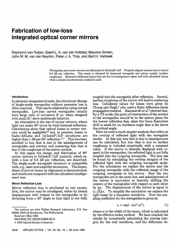
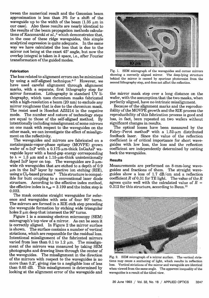
Figure 1 is a scanning electron microscopy (SEM)micrograph's top view of a mirror. As can be seen itis correctly aligned. In Figure 2 the mirror surfaceis shown. The surface contains a number of verticalstriations, which are responsible for the residual loss.Intentional misalignment of the fabricated mirrorsvaried from less than 0.1 to 1.2 jim. The misalign-ment of the mirrors was measured by taking SEMphotographs and drawing lines through the center ofthe waveguides. The misalignment in the directionof the mirrors with respect to the waveguides is nomore than 0.20, giving rise to a negligible loss of lessthan 0.05 dB. This misalignment is determined bylooking at the alignment error of the waveguide and
Fig. 1. SEM micrograph of the waveguides and corner mirrorsshowing a correctly aligned mirror. The deep-lying structurebehind the mirror is caused by spurious photoresist from thesecond lithography step, and does not affect the reflection.
the mirror mask step over a long distance on thewafer, with the assumption that the two masks, whenperfectly aligned, have no intrinsic misalignment.
Because of the alignment marks and the reproduc-ibility of the MOVPE growth and the RIE process thereproducibility of this fabrication process is good andhas, in fact, been repeated on two wafers withoutsignificant changes in results.
The optical losses have been measured by theFabry-Perot method9 with a 1.52-,um distributedfeedback laser. Since the value of the reflectioncoefficient is of critical importance for short wave-guides with low loss, the loss and the reflectioncoefficient are independently determined by cuttingback the waveguides.
Results
Measurements are performed on 8-mm-long wave-guides and fractions of them. The straight wave-guides show a loss of 1.7 dB/cm and a reflectioncoefficient R of 0.31 for TE light. The value of the Ragrees quite well with the calculated value of R =0.312 for this structure, according to Buus.10
Fig. 2. SEM micrograph of a mirror surface. The vertical stria-tions may cause a scattering of light, which results in reflectionloss. Vertical striations of the mirror and waveguide are identicalwhen viewed from the same angle. The apparent inequality of thewaveguides is a result of the tilted view.
20 June 1993 / Vol. 32, No. 18 / APPLIED OPTICS 3247
3.5-
3-
2.5 +T
4 4
1.5
0.5-
0-1.5 -1 -0.5 0 0.5 1 1.5
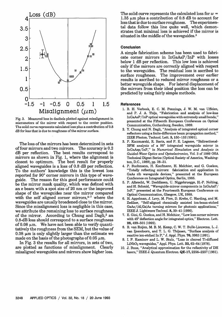
Misalignment (um)Fig. 3. Measured loss in decibels plotted against misalignment inmicrometers of the mirror with respect to the center position.The solid curve represents calculated loss plus a contribution of 0.8dB for loss that is due to roughness of the mirror surface.
The loss of the mirrors has been determined in setsof four mirrors and two mirrors. The accuracy is 0.2dB per reflection. The best results correspond tomirrors as shown in Fig. 1, where the alignment isclosest to optimum. The best result for properlyaligned waveguides is a loss of 0.8 dB per reflection.To the authors' knowledge this is the lowest lossreported for 900 corner mirrors in this type of wave-guide. The reason for this good performance couldbe the mirror mask quality, which was defined withan e beam with a spot size of 20 nm or the improvedshape of the waveguides near the mirror comparedwith the self aligned corner mirrors,>7 where thewaveguides are usually broadened close to the mirror.Since the misalignment loss is negligible in this case,we attribute the remaining loss to surface roughnessof the mirror. According to Chung and Dagli, an0.8-dB loss should correspond to a surface roughnessof 0.08 jim. We have not been able to verify quanti-tatively the roughness from the SEM, but the value of0.08 jim is only slightly larger than the estimate wemade on the basis of the photographs of 0.05 m.
In Fig. 3 the results for all mirrors, in sets of two,are plotted as functions of misalignment. Clearlymisaligned waveguides and mirrors show higher loss.
The solid curve represents the calculated loss for w =1.35 jim plus a contribution of 0.8 dB to account forloss that is due to surface roughness. The experimen-tal data follow this line quite well, which demon-strates that minimal loss is achieved if the mirror issituated in the middle of the waveguides.3
Conclusion
A simple fabrication scheme has been used to fabri-cate corner mirrors in InGaAsP/InP with lossesbelow 1 dB per reflection. This low loss is achievedonly if the mirrors are correctly aligned with respectto the waveguides. The residual loss is ascribed tosurface roughness. The improvement over earlierresults is ascribed to reduced mirror roughness or abetter waveguide shape. For lateral displacement ofthe mirrors from their ideal position the loss can bepredicted by using fairly simple methods.
References1. B. H. Verbeek, E. C. M. Pennings, J. W. M. van Uffelen,
and P. J. A. Thijs, "Fabrication and analysis of low-lossInGaAsP/InP optical waveguides with extremely small bends,"presented at the Fifteenth European Conference on OpticalCommunication, Gothenburg, Sweden, 1989.
2. Y. Chung and N. Dagli, "Analysis of integrated optical cornerreflectors using a finite-difference beam propagation method,"IEEE Photon. Technol. Lett. 3, 150-152 (1991).
3. P. Kaczmarski, R. Baets, and P. E. Lagasse, "Bidirectional-BPM analysis of a 90° integrated waveguide mirror inInGaAsp/InP," in Numerical Simulation and Analysis inGuided-Wave Optics and Optoelectronics, Vol. 3 of 1989 OSATechnical Digest Series (Optical Society of America, Washing-ton, D.C., 1989), pp. 28-31.
4. P. Buchmann, H. Kaufmann, H. Melchior, and G. Guekos,"Totally reflecting mirrors: fabrication and application inGaAs rib waveguide devices," presented at the EuropeanConference on Integrated Optics, Berlin, 1985.
5. P. Albrecht, W. Doeldissen, U. Niggebruegge, H.-P. Nolting,and H. Schmid, "Waveguide-mirror components in InGaAsP/InP," presented at the Fourteenth European Conference onOptical Communication, Glasgow, UK, 1988.
6. H. Appelman, J. Levy, M. Pion, D. Krebs, C. Harding, and M.Zediker, "Self-aligned chemically assisted ion-beam-etchedGaAs/(AI,Ga)As turning mirrors for photonic applications,"IEEE J. Lightwave Technol. 8, 39-41 (1990).
7. E. Gini, G. Guekos, and H. Melchior, "Low loss corner mirrorswith 450 deflection angle for integrated optics," Electron. Lett.28, 499-501 (1992).
8. R. van Roijen, M. B. M. Kemp, C. W. T. Bulle-Lieuwma, L. J.van Ijzendoorn, and T. L. G. Thijssen, "Surface analysis ofreactive ion-etched In P," J. Appl. Phys. 70, 3983 (1991).
9. I. P. Kaminov and L. W. Stulz, "Loss in cleaved Ti-diffusedLiNbO 3 waveguides," Appl. Phys. Lett. 33, 62-64 (1978).
10. J. Buus, "Analytical approximation for the reflectivity of DHlasers," IEEE J. Quantum Electron. QE-17,2256-2257 (1981).
3248 APPLIED OPTICS / Vol. 32, No. 18 / 20 June 1993


![Fabrication and characterization of nanocomposite-based ... · mirrors [6,7,8], reflective thin membrane [9], MEMS tunable gratings [10,11]) suffer of several drawbacks in terms](https://img.pdfslide.us/doc/110x75/5d5ad1bb88c99330748bc3cc/fabrication-and-characterization-of-nanocomposite-based-mirrors-678.jpg)