Embed Size (px)
Citation preview
HIGH-TEMPERATURE ALLOYS
H-3159A
Contents
Introduction 3
Hot Working 6
Cold Working 8
Cutting and Shearing 12
Heat Treatment 13
Welding 23
Health and SafetyInformation 37
Brazing 38
Descaling and Pickling 41
Machining 43
Grinding 48
Appendix I - ColdWork & Anneal Data 49
Appendix II - TypicalSpecifications 58
General Guidelines forHot Working, Cold Working,Heat Treating, Joining,Descaling and Pickling, andFinishing.
©2002, Haynes International, Inc.
FABRICATION OF HAYNES® AND HASTELLOY®
SOLID-SOLUTION-STRENGTHENEDHIGH-TEMPERATURE ALLOYS
HAYNES® 556™ alloy is aniron-nickel-cobalt-chromiumalloy with very good hightemperature strength andoutstanding resistance to awide range of high-tempera-ture aggressive environments.Developed as an upgrade anddirect substitute forMULTIMET® alloy (alloy N-155), 556 alloy has very goodoxidation resistance up to2000°F (1095°C). It hasexcellent resistance tosulfidizing, carburizing, andchlorine-bearing environments.It is also very resistant tocorrosion by molten zinc, andresists molten chloride salts.Components of 556 alloy areeasily fabricated by conven-tional techniques, and the alloyis castable.
Principal applications for 556alloy include replacement forMULTIMET alloy in gas turbineand aerospace components;internals in waste incinerators,chemical plants, and powerplants; hot dip galvanizing andheat treating fixtures; calciningfacilities; and ASME VesselCode construction. It is alsoan excellent dissimilar fillermetal for joining various iron-,nickel-, and cobalt-basedhigh-temperature alloys.
Ask for brochure H-3013
3
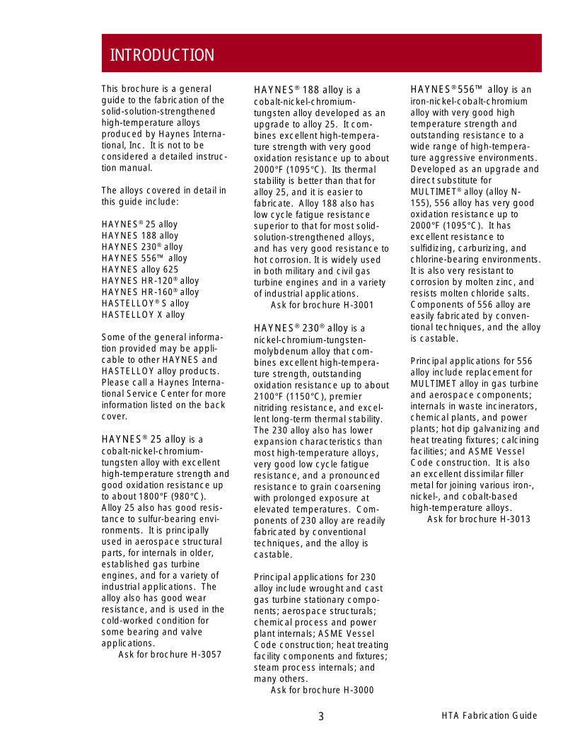
This brochure is a generalguide to the fabrication of thesolid-solution-strengthenedhigh-temperature alloysproduced by Haynes Interna-tional, Inc. It is not to beconsidered a detailed instruc-tion manual.
The alloys covered in detail inthis guide include:
HAYNES® 25 alloyHAYNES 188 alloyHAYNES 230® alloyHAYNES 556™ alloyHAYNES alloy 625HAYNES HR-120® alloyHAYNES HR-160® alloyHASTELLOY® S alloyHASTELLOY X alloy
Some of the general informa-tion provided may be appli-cable to other HAYNES andHASTELLOY alloy products.Please call a Haynes Interna-tional Service Center for moreinformation listed on the backcover.
HAYNES® 25 alloy is acobalt-nickel-chromium-tungsten alloy with excellenthigh-temperature strength andgood oxidation resistance upto about 1800°F (980°C).Alloy 25 also has good resis-tance to sulfur-bearing envi-ronments. It is principallyused in aerospace structuralparts, for internals in older,established gas turbineengines, and for a variety ofindustrial applications. Thealloy also has good wearresistance, and is used in thecold-worked condition forsome bearing and valveapplications.
Ask for brochure H-3057
HAYNES® 188 alloy is acobalt-nickel-chromium-tungsten alloy developed as anupgrade to alloy 25. It com-bines excellent high-tempera-ture strength with very goodoxidation resistance up to about2000°F (1095°C). Its thermalstability is better than that foralloy 25, and it is easier tofabricate. Alloy 188 also haslow cycle fatigue resistancesuperior to that for most solid-solution-strengthened alloys,and has very good resistance tohot corrosion. It is widely usedin both military and civil gasturbine engines and in a varietyof industrial applications.
Ask for brochure H-3001
HAYNES® 230® alloy is anickel-chromium-tungsten-molybdenum alloy that com-bines excellent high-tempera-ture strength, outstandingoxidation resistance up to about2100°F (1150°C), premiernitriding resistance, and excel-lent long-term thermal stability.The 230 alloy also has lowerexpansion characteristics thanmost high-temperature alloys,very good low cycle fatigueresistance, and a pronouncedresistance to grain coarseningwith prolonged exposure atelevated temperatures. Com-ponents of 230 alloy are readilyfabricated by conventionaltechniques, and the alloy iscastable.
Principal applications for 230alloy include wrought and castgas turbine stationary compo-nents; aerospace structurals;chemical process and powerplant internals; ASME VesselCode construction; heat treatingfacility components and fixtures;steam process internals; andmany others.
Ask for brochure H-3000
HTA Fabrication Guide
INTRODUCTION
4HTA Fabrication Guide
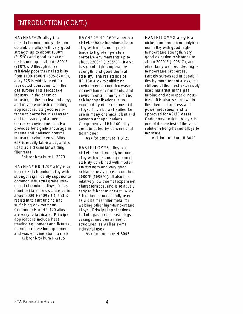
HASTELLOY® X alloy is anickel-iron-chromium-molybde-num alloy with good high-temperature strength, verygood oxidation resistance toabout 2000°F (1095°C), andother fairly well-rounded high-temperature properties.Largely surpassed in capabili-ties by more recent alloys, it isstill one of the most extensivelyused materials in the gasturbine and aerospace indus-tries. It is also well known inthe chemical process andpower industries, and isapproved for ASME VesselCode construction. Alloy X isone of the easiest of the solid-solution-strengthened alloys tofabricate.
Ask for brochure H-3009
HAYNES® HR-160® alloy is anickel-cobalt-chromium-siliconalloy with outstanding resis-tance to high-temperaturecorrosive environments up toabout 2200°F (1205°C). It alsohas good high-temperaturestrength, and good thermalstability. The resistance ofHR-160 alloy to sulfidizingenvironments, complex wasteincineration enviornments, andenvironments in many kiln andcalciner applications is un-matched by other commercialalloys. It is also well suited foruse in many chemical plant andpower plant applications.Components of HR-160 alloyare fabricated by conventionaltechniques.
Ask for brochure H-3129
HASTELLOY® S alloy is anickel-chromium-molybdenumalloy with outstanding thermalstability combined with moder-ate strength and very goodoxidation resistance up to about2000°F (1095°C). It also hasrelatively low thermal expansioncharacteristics, and is relativelyeasy to fabricate or cast. AlloyS has been successfully usedas a dissimilar filler metal forwelding other high-temperaturealloys. Principal applicationsinclude gas turbine seal rings,casings, and containmentstructures, as well as someindustrial uses
Ask for brochure H-3003
HAYNES® 625 alloy is anickel-chromium-molybdenum-columbium alloy with very goodstrength up to about 1500°F(815°C) and good oxidationresistance up to about 1800°F(980°C). Although it hasrelatively poor thermal stabilityfrom 1100-1600°F (595-870°C),alloy 625 is widely used forfabricated components in thegas turbine and aerospaceindustry, in the chemicalindustry, in the nuclear industry,and in some industrial heatingapplications. Its good resis-tance to corrosion in seawater,and to a variety of aqueouscorrosive environments, alsoprovides for significant usage inmarine and pollution controlindustry environments. Alloy625 is readily fabricated, and isused as a dissimilar weldingfiller metal.
Ask for brochure H-3073
HAYNES® HR-120® alloy is aniron-nickel-chromium alloy withstrength significantly superior tocommon industrial grade iron-nickel-chromium alloys. It hasgood oxidation resistance up toabout 2000°F (1095°C), and isresistant to carburizing andsulfidizing environments.Components of HR-120 alloyare easy to fabricate. Principalapplications include heattreating equipment and fixtures,thermal processing equipment,and waste incinerator internals.
Ask for brochure H-3125
INTRODUCTION (CON'T.)
HTA Fabrication Guide
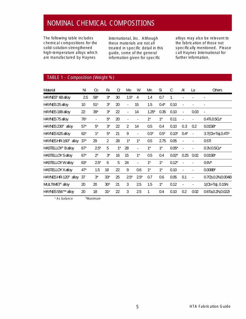
Material Ni Co Fe Cr Mo W Mn Si C Al La Others
HAYNES® 6B alloy 2.5 58a 3* 30 1.5* 4 1.4 0.7 1 - - -
HAYNES 25 alloy 10 51a 3* 20 - 15 1.5 0.4* 0.10 - - -
HAYNES 188 alloy 22 39a 3* 22 - 14 1.25* 0.35 0.10 - 0.03 -
HAYNES 75 alloy 76a - 5* 20 - - 1* 1* 0.11 - - 0.4Ti,0.5Cu*
HAYNES 230® alloy 57a 5* 3* 22 2 14 0.5 0.4 0.10 0.3 0.2 0.015B*
HAYNES 625 alloy 62a 1* 5* 21 9 - 0.5* 0.5* 0.10* 0.4* - 3.7(Cb+Ta),0.4Ti*
HAYNES HR-160® alloy 37a 29 2 28 1* 1* 0.5 2.75 0.05 - - 0.5Ti
HASTELLOY® B alloy 67a 2.5* 5 1* 28 - 1* 1* 0.05* - - 0.3V,0.5Cu*
HASTELLOY S alloy 67a 2* 3* 16 15 1* 0.5 0.4 0.02* 0.25 0.02 0.015B*
HASTELLOY W alloy 63a 2.5* 6 5 24 - 1* 1* 0.12* - - 0.6V*
HASTELLOY X alloy 47a 1.5 18 22 9 0.6 1* 1* 0.10 - - 0.008B*
HAYNES HR-120® alloy 37 3* 33a 25 2.5* 2.5* 0.7 0.6 0.05 0.1 - 0.7Cb,0.2N,0.004B
MULTIMET® alloy 20 20 30a 21 3 2.5 1.5 1* 0.12 - - 1(Cb+Ta), 0.15N
HAYNES 556™ alloy 20 18 31a 22 3 2.5 1 0.4 0.10 0.2 0.02 0.6Ta,0.2N,0.02Zr
alloys may also be relevant tothe fabrication of those notspecifically mentioned. Pleasecall Haynes International forfurther information.
International, Inc. Althoughthese materials are not alltreated in specific detail in thisguide, some of the generalinformation given for specific
The following table includeschemical compositions for thesolid-solution-strengthenedhigh-temperature alloys whichare manufactured by Haynes
NOMINAL CHEMICAL COMPOSITIONS
5
a As balance *Maximum
TABLE 1 - Composition (Weight %)
6HTA Fabrication Guide
falls to the low end of the hotworking range. Accordingly,hot working practices whichincorporate heavy initial andmoderate final reductions,coupled with frequent reheat-ing, often yield the best results.In addition, slow deformationrates tend to minimize adia-batic heating and appliedforce requirements.
The characteristics of solid-solution-strengthened high-temperature alloys which mustbe considered in developing aparticular hot working practiceinclude (1) relatively low meltingtemperatures; (2) high hotstrength; (3) rapid work harden-ing; and (4) relatively lowthermal conductivity. Further-more, the resistance to defor-mation in these alloys mayincrease rapidly as temperature
HAYNES® and HASTELLOY®
high-temperature alloys may behot worked into various forms;however, these alloys can bemore sensitive to the amountand rate of hot reduction than istypical for austenitic stainlesssteels. In addition, the hotworking temperature ranges forthese alloys can be narrow.Particular care must be exer-cised during hot working inorder to achieve satisfactoryresults.
● Do not make radicalchanges in the crosssectional shape, such asgoing from a square directlyto a round, during initialforming stages. Instead, gofrom square to round-cornered-square to octagonto round.
● Condition out any cracks ortears developed duringforging. Very often this canbe done at intermediatestages between forgingsessions.
The hot working temperatureranges recommended forHAYNES and HASTELLOYhigh-temperature alloys aregiven in Table 2.
● Moderately heavy reductions(25 to 40 percent) arebeneficial to maintain asmuch internal heat as pos-sible, thus minimizing graincoarsening and the numberof reheatings. Reductionsgreater than 40 percent persession should be avoided.
● Care must be taken to impartsufficient hot work duringforging to ensure that appro-priate structure and proper-ties are achieved in the finalpart. For parts with largecross sections, it is advisableto include a number offorging upsets in the hotworking schedule to allow foradequate forging reductions.Upset L/D ratios of 3:1 aregenerally acceptable.
● Light-reduction finish sizingsessions should generally beavoided. If required, theyshould be performed at thelower end of the forgingtemperature range.
The following are general rulesto follow in forging these alloys:
● Soak billets or ingots at least1/2 hour at forging tempera-ture for each inch (25 mm) ofthickness. The use of a well-calibrated optical pyrometeris essential.
● The stock should be turnedfrequently to present thecooler side to the furnaceatmosphere. Direct flameimpingement on the alloymust be avoided.
● Forging should begin imme-diately after withdrawal fromthe furnace. A short timelapse may allow surfacetemperature to drop as muchas 100 to 200°F (38 to93°C). Do not raise theforging temperature tocompensate for heat loss, asthis may cause incipientmelting.
HOT WORKING
FORGING
7 HTA Fabrication Guide
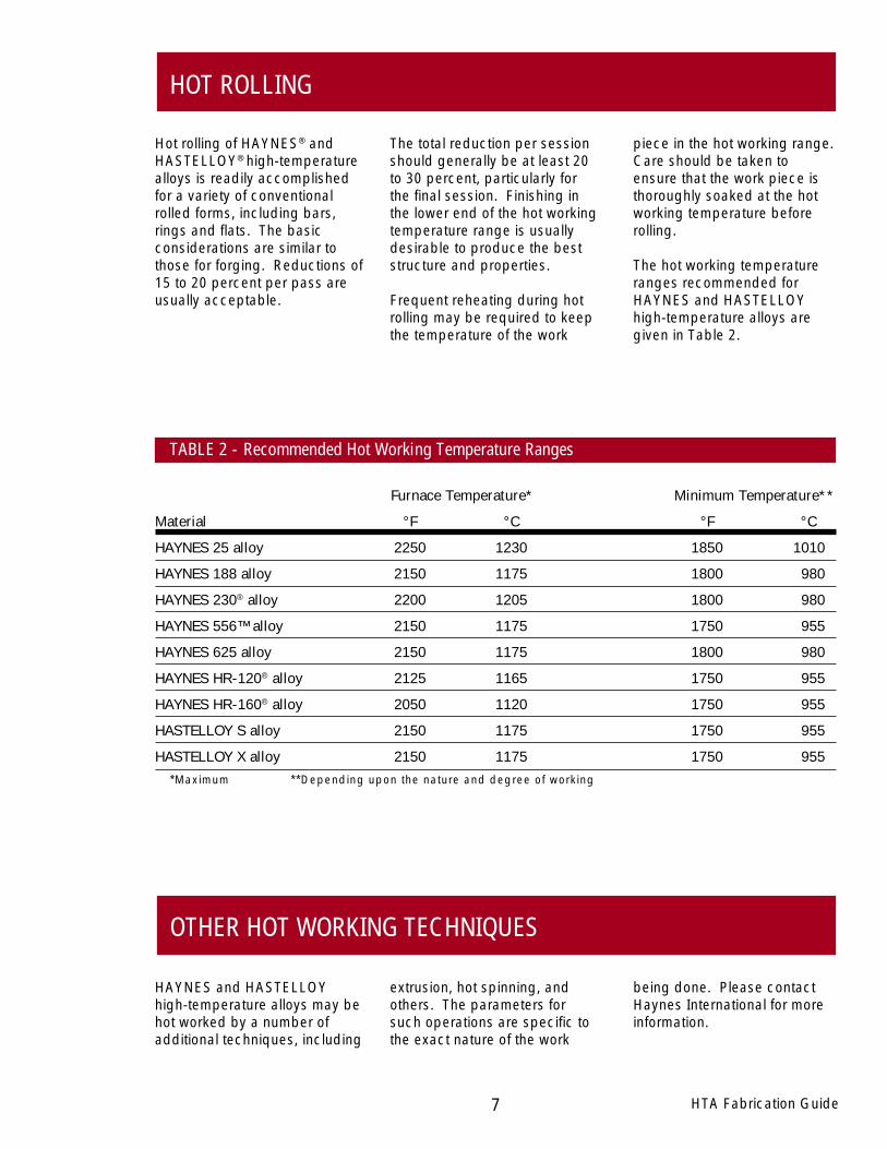
Hot rolling of HAYNES® andHASTELLOY® high-temperaturealloys is readily accomplishedfor a variety of conventionalrolled forms, including bars,rings and flats. The basicconsiderations are similar tothose for forging. Reductions of15 to 20 percent per pass areusually acceptable.
The total reduction per sessionshould generally be at least 20to 30 percent, particularly forthe final session. Finishing inthe lower end of the hot workingtemperature range is usuallydesirable to produce the beststructure and properties.
Frequent reheating during hotrolling may be required to keepthe temperature of the work
piece in the hot working range.Care should be taken toensure that the work piece isthoroughly soaked at the hotworking temperature beforerolling.
The hot working temperatureranges recommended forHAYNES and HASTELLOYhigh-temperature alloys aregiven in Table 2.
HAYNES and HASTELLOYhigh-temperature alloys may behot worked by a number ofadditional techniques, including
extrusion, hot spinning, andothers. The parameters forsuch operations are specific tothe exact nature of the work
being done. Please contactHaynes International for moreinformation.
Furnace Temperature* Minimum Temperature**
Material °F °C °F °C
HAYNES 25 alloy 2250 1230 1850 1010
HAYNES 188 alloy 2150 1175 1800 980
HAYNES 230® alloy 2200 1205 1800 980
HAYNES 556™ alloy 2150 1175 1750 955
HAYNES 625 alloy 2150 1175 1800 980
HAYNES HR-120® alloy 2125 1165 1750 955
HAYNES HR-160® alloy 2050 1120 1750 955
HASTELLOY S alloy 2150 1175 1750 955
HASTELLOY X alloy 2150 1175 1750 955
HOT ROLLING
OTHER HOT WORKING TECHNIQUES
*Maximum **Depending upon the nature and degree of working
TABLE 2 - Recommended Hot Working Temperature Ranges
HAYNES® and HASTELLOY ® high-temperature alloys may be readilyformed into various configurations bycold working. Since they are gener-ally stronger, and work harden morerapidly than austenitic stainlesssteels, the application of greater forceis normally required to achieve thesame amount of cold deformation.The higher yield strength of thesealloys may also result in greaterspring back during cold forming thanseen for stainless steels. Further-more, the rapid work hardeningcharacteristics of these alloys maynecessitate more frequent intermedi-ate annealing between forming stepsto make a finished part.
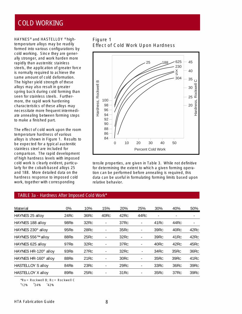
The effect of cold work upon the roomtemperature hardness of variousalloys is shown in Figure 1. Results tobe expected for a typical austeniticstainless steel are included forcomparison. The rapid developmentof high hardness levels with imposedcold work is clearly evident, particu-larly for the cobalt-based alloys 25and 188. More detailed data on thehardness response to imposed coldwork, together with corresponding
Figure 1Effect of Cold Work Upon Hardness
1009896949290888684
0 10 20 30 40 50
Har
dnes
s, R
ockw
ell B
Har
dnes
s, R
ockw
ell C
20
25
30
35
40
4525 188 625230XS304
Percent Cold Work
tensile properties, are given in Table 3. While not definitivefor determining the extent to which a given forming opera-tion can be performed before annealing is required, thisdata can be useful in formulating forming limits based uponrelative behavior.
HTA Fabrication Guide 8
Material 0% 10% 15% 20% 25% 30% 40% 50%
HAYNES 25 alloy 24RC 36RC 40RC 42RC 44RC - - -
HAYNES 188 alloy 98RB 32RC - 37RC - 41RC 44RC -
HAYNES 230® alloy 95RB 28RC - 35RC - 39RC 40RC 42RC
HAYNES 556™ alloy 88RB 25RC - 32RC - 39RC 41RC 42RC
HAYNES 625 alloy 97RB 32RC - 37RC - 40RC 42RC 45RC
HAYNES HR-120® alloy 93RB 27RC - 32RC - 34RC 35RC 36RC
HAYNES HR-160® alloy 88RB 21RC - 30RC - 35RC 39RC 41RC
HASTELLOY S alloy 84RB 23RC - 29RC - 33RC 36RC 39RC
HASTELLOY X alloy 89RB 25RC - 31RC - 35RC 37RC 39RC
*RB = Rockwell B; RC = Rockwell Ca12%
b24%
c42%
TABLE 3a - Hardness After Imposed Cold Work*
COLD WORKING

Material 0% 10% 15% 20% 25% 30% 40% 50%
HAYNES® 25 alloy 68 124 149 151 184 - - -
HAYNES 188 alloy 67 106 - 133 - 167 177 -
HAYNES 230® alloy 62 104 - 134 - 160 173 185
HAYNES 556™ alloy 53 93 - 113 - 144 156 170
HAYNES 625 alloy 70 113 - 140 - 162 178 193
HAYNES HR-120® alloy 60 103 - 129 - 143 159 166
HAYNES HR-160® alloy 50 81 - 112 - 145 164 174
HASTELLOY® S alloy 74 92 - 136 - 154 166 177
HASTELLOY X alloy 57 96 - 122 - 142 159 171
9 HTA Fabrication Guide
COLD WORKING (CON'T.)
TABLE 3b - Yield Strength After Imposed Cold Work (Ksi)*
Material 0% 10% 15% 20% 25% 30% 40% 50%
HAYNES 25 alloy 58 37 28 18 15 - - -
HAYNES 188 alloy 54 45 - 28 - 13 10 -
HAYNES 230 alloy 47 32 - 17 - 10 8 6
HAYNES 556 alloy 51 35 - 24 - 12 10 8
HAYNES 625 alloy 46 31 - 16 - 11 8 5
HAYNES HR-120 alloy 39 26 - 11 - 6 6 5
HAYNES HR-160 alloy 68 52 - 28 - 13 9 8
HASTELLOY S alloy 45 38 - 17 - 10 9 7
HASTELLOY X alloy 46 29 - 15 - 10 8 8
TABLE 3c - Tensile Elongation After Imposed Cold Work (%)
*To convert to MPa multiply by 6.895
10HTA Fabrication Guide
To produce satisfactory parts,the condition of the materialmust be closely monitoredthroughout the forming opera-tion. Material is normallysupplied in the solution-annealed or mill-annealedcondition, and is generallysuitable for mild to moderateforming as-received. Eachsuccessive operation should befollowed by an intermediateanneal to restore ductility.Intermediate annealing shouldbe performed in accordancewith the recommendationsgiven in the HEAT TREATMENTsection of this guide.
Lubrication is a significantconsideration for successfullycold working these alloys.Although lubrication is seldomrequired for a simple bendingoperation, for example, the useof lubricants may be essentialfor other forming operations,such as cold drawing. Mildforming operations can besuccessfully completed byusing lard oil or castor oil, whichare easily removed. Moresevere forming operationsrequire metallic soaps orchlorinated or sulfochlorinatedoils.
CAUTION: When the sulfo-chlorinated oils are used, thework-piece must be carefullycleaned in a degreaser oralkaline cleaner.
Lubricants that contain whitelead, zinc compounds, ormolybdenum disulfide are notrecommended because theyare difficult to remove prior tothe final anneal. Also lead,zinc, and sulfur can severelyembrittle these alloys. Careshould be taken to remove diematerial, lubricants, or otherforeign materials from the partbefore annealing as many ofthese preparations will affectthe properties of the alloys.
HAYNES and HASTELLOYhigh-temperature alloys may beformed by deep drawing,stretch forming, hydroforming,and other similar operations.Lubrication is generally re-quired. Specially produced
fine-grain-size starting materialmay provide superior perfor-mance in these types of formingoperations. Heavy sectionthickness parts may requiremultiple forming steps, accom-panied by appropriate interme-
diate anneals as given in theHEAT TREATMENT section ofthis guide.
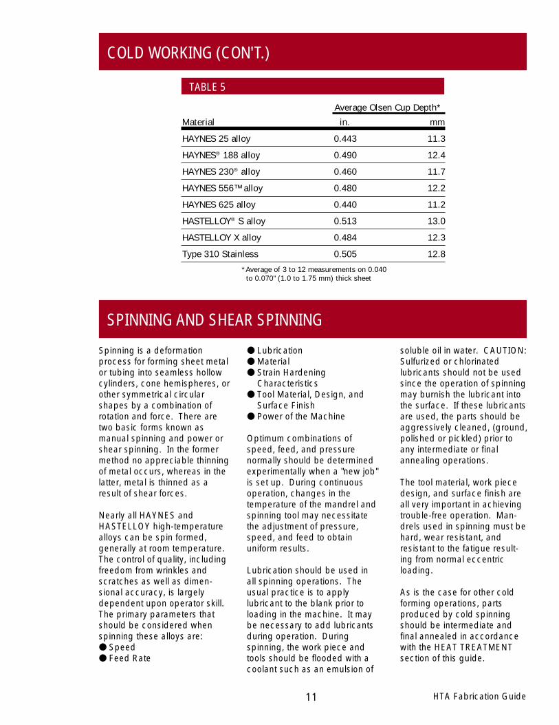
Comparative standard Olsencup test results (lubricated) forthese alloys are given in Table5 for reference.
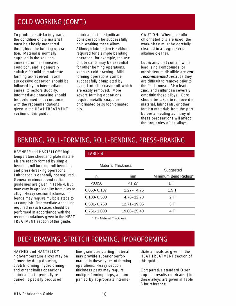
Material ThicknessSuggested
in. mm Minimum Bend Radius*
<0.050 <1.27 1 T
0.050- 0.187 1.27 - 4.75 1.5 T
0.188- 0.500 4.76 - 12.70 2 T
0.501- 0.750 12.71 - 19.05 3 T
0.751- 1.000 19.06 - 25.40 4 T
* T = Material Thickness
HAYNES® and HASTELLOY® high-temperature sheet and plate materi-als are readily formed by simplebending, roll-forming, roll-bending,and press-breaking operations.Lubrication is generally not required.General minimum bend radiusguidelines are given in Table 4, butmay vary in applicability from alloy toalloy. Heavy section thicknessbends may require multiple steps toaccomplish. Intermediate annealingrequired in such cases should beperformed in accordance with therecommendations given in the HEATTREATMENT section of this guide.
BENDING, ROLL-FORMING, ROLL-BENDING, PRESS-BRAKING
TABLE 4
COLD WORKING (CON'T.)
DEEP DRAWING, STRETCH FORMING, HYDROFORMING
11 HTA Fabrication Guide
COLD WORKING (CON'T.)
Average Olsen Cup Depth*
Material in. mm
HAYNES 25 alloy 0.443 11.3
HAYNES® 188 alloy 0.490 12.4
HAYNES 230® alloy 0.460 11.7
HAYNES 556™ alloy 0.480 12.2
HAYNES 625 alloy 0.440 11.2
HASTELLOY® S alloy 0.513 13.0
HASTELLOY X alloy 0.484 12.3
Type 310 Stainless 0.505 12.8
*Average of 3 to 12 measurements on 0.040 to 0.070" (1.0 to 1.75 mm) thick sheet
SPINNING AND SHEAR SPINNING
Spinning is a deformationprocess for forming sheet metalor tubing into seamless hollowcylinders, cone hemispheres, orother symmetrical circularshapes by a combination ofrotation and force. There aretwo basic forms known asmanual spinning and power orshear spinning. In the formermethod no appreciable thinningof metal occurs, whereas in thelatter, metal is thinned as aresult of shear forces.
Nearly all HAYNES andHASTELLOY high-temperaturealloys can be spin formed,generally at room temperature.The control of quality, includingfreedom from wrinkles andscratches as well as dimen-sional accuracy, is largelydependent upon operator skill.The primary parameters thatshould be considered whenspinning these alloys are:● Speed● Feed Rate
● Lubrication● Material● Strain Hardening
Characteristics● Tool Material, Design, and
Surface Finish● Power of the Machine
Optimum combinations ofspeed, feed, and pressurenormally should be determinedexperimentally when a "new job"is set up. During continuousoperation, changes in thetemperature of the mandrel andspinning tool may necessitatethe adjustment of pressure,speed, and feed to obtainuniform results.
Lubrication should be used inall spinning operations. Theusual practice is to applylubricant to the blank prior toloading in the machine. It maybe necessary to add lubricantsduring operation. Duringspinning, the work piece andtools should be flooded with acoolant such as an emulsion of
soluble oil in water. CAUTION:Sulfurized or chlorinatedlubricants should not be usedsince the operation of spinningmay burnish the lubricant intothe surface. If these lubricantsare used, the parts should beaggressively cleaned, (ground,polished or pickled) prior toany intermediate or finalannealing operations.
The tool material, work piecedesign, and surface finish areall very important in achievingtrouble-free operation. Man-drels used in spinning must behard, wear resistant, andresistant to the fatigue result-ing from normal eccentricloading.
As is the case for other coldforming operations, partsproduced by cold spinningshould be intermediate andfinal annealed in accordancewith the HEAT TREATMENTsection of this guide.
TABLE 5
12
AQUEOUS CORROSION RESISTANCE
HAYNES® and HASTELLOY®
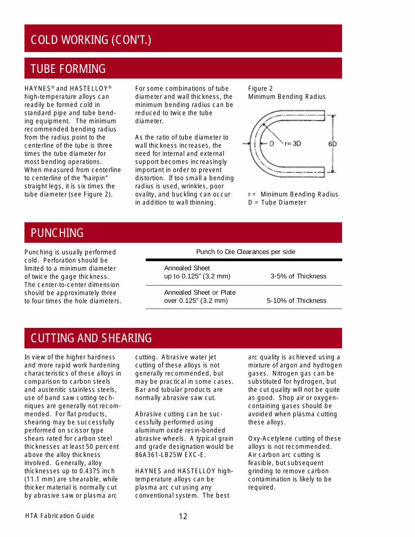
high-temperature alloys canreadily be formed cold instandard pipe and tube bend-ing equipment. The minimumrecommended bending radiusfrom the radius point to thecenterline of the tube is threetimes the tube diameter formost bending operations.When measured from centerlineto centerline of the "hairpin"straight legs, it is six times thetube diameter (see Figure 2).
Figure 2Minimum Bending Radius
For some combinations of tubediameter and wall thickness, theminimum bending radius can bereduced to twice the tubediameter.
As the ratio of tube diameter towall thickness increases, theneed for internal and externalsupport becomes increasinglyimportant in order to preventdistortion. If too small a bendingradius is used, wrinkles, poorovality, and buckling can occurin addition to wall thinning.
r = Minimum Bending RadiusD = Tube Diameter
In view of the higher hardnessand more rapid work hardeningcharacteristics of these alloys incomparison to carbon steelsand austenitic stainless steels,use of band saw cutting tech-niques are generally not recom-mended. For flat products,shearing may be successfullyperformed on scissor typeshears rated for carbon steelthicknesses at least 50 percentabove the alloy thicknessinvolved. Generally, alloythicknesses up to 0.4375 inch(11.1 mm) are shearable, whilethicker material is normally cutby abrasive saw or plasma arc
arc quality is achieved using amixture of argon and hydrogengases. Nitrogen gas can besubstituted for hydrogen, butthe cut quality will not be quiteas good. Shop air or oxygen-containing gases should beavoided when plasma cuttingthese alloys.
Oxy-Acetylene cutting of thesealloys is not recommended.Air carbon arc cutting isfeasible, but subsequentgrinding to remove carboncontamination is likely to berequired.
cutting. Abrasive water jetcutting of these alloys is notgenerally recommended, butmay be practical in some cases.Bar and tubular products arenormally abrasive saw cut.
Abrasive cutting can be suc-cessfully performed usingaluminum oxide resin-bondedabrasive wheels. A typical grainand grade designation would be86A361-LB25W EXC-E.
HAYNES and HASTELLOY high-temperature alloys can beplasma arc cut using anyconventional system. The best
Punching is usually performedcold. Perforation should belimited to a minimum diameterof twice the gage thickness.The center-to-center dimensionshould be approximately threeto four times the hole diameters.
HTA Fabrication Guide
Punch to Die Clearances per side
Annealed Sheetup to 0.125" (3.2 mm) 3-5% of Thickness
Annealed Sheet or Plateover 0.125" (3.2 mm) 5-10% of Thickness
COLD WORKING (CON'T.)
TUBE FORMING
PUNCHING
CUTTING AND SHEARING
13 HTA Fabrication Guide
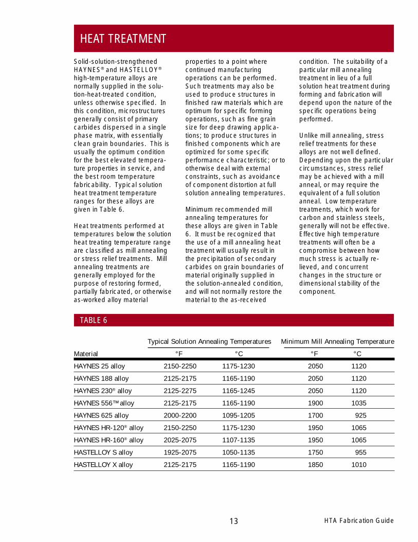
Typical Solution Annealing Temperatures Minimum Mill Annealing Temperature
Material °F °C °F °C
HAYNES 25 alloy 2150-2250 1175-1230 2050 1120
HAYNES 188 alloy 2125-2175 1165-1190 2050 1120
HAYNES 230® alloy 2125-2275 1165-1245 2050 1120
HAYNES 556™ alloy 2125-2175 1165-1190 1900 1035
HAYNES 625 alloy 2000-2200 1095-1205 1700 925
HAYNES HR-120® alloy 2150-2250 1175-1230 1950 1065
HAYNES HR-160® alloy 2025-2075 1107-1135 1950 1065
HASTELLOY S alloy 1925-2075 1050-1135 1750 955
HASTELLOY X alloy 2125-2175 1165-1190 1850 1010
Solid-solution-strengthenedHAYNES® and HASTELLOY®
high-temperature alloys arenormally supplied in the solu-tion-heat-treated condition,unless otherwise specified. Inthis condition, microstructuresgenerally consist of primarycarbides dispersed in a singlephase matrix, with essentiallyclean grain boundaries. This isusually the optimum conditionfor the best elevated tempera-ture properties in service, andthe best room temperaturefabricability. Typical solutionheat treatment temperatureranges for these alloys aregiven in Table 6.
Heat treatments performed attemperatures below the solutionheat treating temperature rangeare classified as mill annealingor stress relief treatments. Millannealing treatments aregenerally employed for thepurpose of restoring formed,partially fabricated, or otherwiseas-worked alloy material
condition. The suitability of aparticular mill annealingtreatment in lieu of a fullsolution heat treatment duringforming and fabrication willdepend upon the nature of thespecific operations beingperformed.
Unlike mill annealing, stressrelief treatments for thesealloys are not well defined.Depending upon the particularcircumstances, stress reliefmay be achieved with a millanneal, or may require theequivalent of a full solutionanneal. Low temperaturetreatments, which work forcarbon and stainless steels,generally will not be effective.Effective high temperaturetreatments will often be acompromise between howmuch stress is actually re-lieved, and concurrentchanges in the structure ordimensional stability of thecomponent.
properties to a point wherecontinued manufacturingoperations can be performed.Such treatments may also beused to produce structures infinished raw materials which areoptimum for specific formingoperations, such as fine grainsize for deep drawing applica-tions; to produce structures infinished components which areoptimized for some specificperformance characteristic; or tootherwise deal with externalconstraints, such as avoidanceof component distortion at fullsolution annealing temperatures.
Minimum recommended millannealing temperatures forthese alloys are given in Table6. It must be recognized thatthe use of a mill annealing heattreatment will usually result inthe precipitation of secondarycarbides on grain boundaries ofmaterial originally supplied inthe solution-annealed condition,and will not normally restore thematerial to the as-received
TABLE 6
HEAT TREATMENT

14HTA Fabrication Guide
ANNEALING DURING COLD OR WARM FORMINGThe response of HAYNES® andHASTELLOY® high-temperaturealloys to heat treatment is verymuch dependent upon thecondition that the material is inwhen the treatment is applied.When the material is not in acold- or warm-worked condi-tion, the principal response toheat treatment is usually achange in the amount andmorphology of the secondarycarbide phases present. Otherminor effects may occur, butthe grain structure of thematerial will normally be unal-tered by heat treatment whencold or warm work is absent.
When the material is in the cold-or warm-worked condition,application of a mill anneal orsolution heat treatment (asdefined on page 13) will almostalways alter the grain structureof the component. The amountof prior cold or warm work in thepiece will significantly influencethe resulting grain structure andmechanical characteristics ofthe material. The results forseveral combinations of priorcold work and annealingtemperature upon the grain
than 10 percent cold workwhere possible. Smallamounts of cold work can leadto exaggerated or abnormalgrain growth during annealing.The sensitivity to this phenom-enon varies from alloy to alloy,and is dependent uponannealing temperature, asshown in Table 8. In theeveryday fabrication of com-plex components, it may beimpossible to avoid situationswhere such low levels of coldwork or strain are introduced.Procedures which may beeffective for minimizing theproblem are:
● Solution heat treating at thelow end of the allowabletemperature ranges
● Utilizing mill anneals inpreference to solutionanneals for intermediateheat treatments duringcomponent forming
● Performing a mill annealdirectly prior to a finalsolution anneal on a compo-nent.
structure response for sheetproduct of various alloys aregiven in Table 7. More exten-sive results for room tempera-ture hardness, yield strength,and tensile elongation areillustrated in Figures 3 to 5, anddetailed in Appendix I. All ofthese results were used toformulate the minimum millannealing temperatures given inTable 6.
The particular sequence of coldwork or warm work/annealingcycles used in multi-stepcomponent forming can alsohave an effect upon the struc-ture and properties of thesealloys. One general guideline ofparticular importance is to keepthe temperatures used forintermediate annealing steps ator below the final annealingtemperature. Intermediateannealing at temperaturesabove the final annealingtemperature will reduce thedegree of structure controlpossible in the component.
Care should be exercised incold forming these alloys toavoid the imposition of less
ASTM Grain Size Produced**
Cold Anneal HAYNES HAYNES HAYNES HASTELLOYWork Temperature* 25 230® 556™ X
% °F (°C) alloy alloy alloy alloy
0 None 3 1/2 - 4 5 - 6 5 - 6 4 - 5
10 1850 (1010) N/A N/A NR NR
1950 (1065) NR NR NR NR
2050 (1120) NR NFR 5 - 5 1/2 5 - 7
2150 (1175) 4 - 4 1/2 4 - 7 5 - 5 1/2 N/A
2250 (1230) 3 - 4 1/2 6 1/2 - 7 N/A N/A
HEAT TREATMENT (CON'T.)
TABLE 7

ASTM Grain Size Produced**
Cold Anneal HAYNES HAYNES HAYNES HASTELLOYWork Temperature* 25 230® 556™ X
% °F (°C) alloy alloy alloy alloy
15 1950 (1065) 7 N/A N/A N/A
2050 (1120) 6 - 7 N/A N/A N/A
2150 (1175) 5 - 7 N/A N/A N/A
2250 (1230) 3 - 4 1/2 N/A N/A N/A
20 1850 (1010) N/A N/A NR NFR
1950 (1065) 7 - 8 NFR NR NFR
2050 (1120) 7 - 8 8 - 8 1/2 7 1/2 - 8 1/2 7 - 8
2150 (1175) 4 1/2 - 7 7 1/2 - 8 6 - 6 1/2 N/A
2250 (1230) 2 1/2 - 4 1/2 7 - 7 1/2 N/A N/A
25 1950 (1065) 7 1/2 - 8 N/A N/A N/A
2050 (1120) 7 1/2 - 8 N/A N/A N/A
2150 (1175) 4 N/A N/A N/A
2250 (1230) 3 1/2 N/A N/A N/A
30 1850 (1010) N/A N/A NFR NFR
1950 (1065) N/A 8 - 9 7 1/2 - 9 1/2 8 - 10
2050 (1120) N/A 9 - 10 7 - 7 1/2 7 1/2 - 9 1/2
2150 (1175) N/A 8 1/2 - 9 4 1/2 - 6 1/2 N/A
2250 (1230) N/A 6 - 7 N/A N/A
40 1850 (1010) N/A N/A 7 1/2 - 9 1/2 8 - 9
1950 (1065) N/A 9 1/2 - 10 8 - 9 1/2 8 - 10
2050 (1120) N/A 9 - 10 7 - 9 9 1/2 - 10
2150 (1175) N/A 8 1/2 - 9 4 1/2 - 6 1/2 N/A
2250 (1230) N/A 4 - 7 N/A N/A
50 1850 (1010) N/A N/A 9 - 10 8 1/2 - 10
1950 (1065) N/A 9 - 10 8 1/2 - 10 8 1/2 - 10
2050 (1120) N/A 9 - 10 8 - 9 1/2 8 1/2 - 10
2150 (1175) N/A 9 - 9 1/2 5 1/2 - 6 N/A
2250 (1230) N/A 5 1/2 - 6 1/2 N/A N/A
*5 minutes ** N/A = Not Available; NR = No Recrystallization Observed; NFR = Not Fully Recrystallized
15 HTA Fabrication Guide
HEAT TREATMENT (CON'T.)
TABLE 7 (Con't.)

16HTA Fabrication Guide
Figure 4Effect of Anneal Temperature Upon Yield Strength of Cold-Worked Material
Figure 3Effect of Anneal Temperature Upon Hardness of Cold-Worked Material
HEAT TREATMENT (CON'T.)
808284868890929496
35
30
25
45
40
1200 CW 10001100CW 1000 1100 1200
45
40
20
25
30
225020501850CW225020501850CW
80828486889092949698
100
35
Anneal Temperature, °C
Anneal Temperature, °F
Har
dnes
s, R
ockw
ell B
Har
dnes
s, R
ockw
ell C
40% Cold Work20% Cold Work
25188230
556X
1950 2150 21501950
1050 1150 12501050 1150 1250
188230
556
X
25040
60
50080
750
1250
1000
120
180
160
12001100CW 1000
40
60
80
100
120
Anneal Temperature, °C
Anneal Temperature, °F
Yie
ld S
tren
gth,
Ksi
Yie
ld S
tren
gth,
MP
a
20% Cold Work
100
230556X
140
160
180
140
1050 1150 1250
225020501850CW 1950 2150
188
25
1250
750
225020501850CW
1000
40% Cold Work
250
500
12001100CW 1000 1050 1150 1250
1950 2150
230556X
188
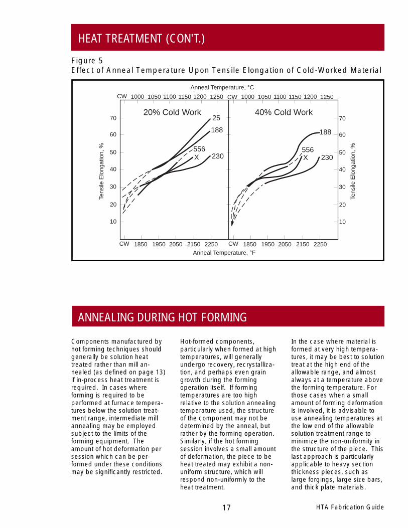
17
Figure 5Effect of Anneal Temperature Upon Tensile Elongation of Cold-Worked Material
HTA Fabrication Guide
Components manufactured byhot forming techniques shouldgenerally be solution heattreated rather than mill an-nealed (as defined on page 13)if in-process heat treatment isrequired. In cases whereforming is required to beperformed at furnace tempera-tures below the solution treat-ment range, intermediate millannealing may be employedsubject to the limits of theforming equipment. Theamount of hot deformation persession which can be per-formed under these conditionsmay be significantly restricted.
In the case where material isformed at very high tempera-tures, it may be best to solutiontreat at the high end of theallowable range, and almostalways at a temperature abovethe forming temperature. Forthose cases when a smallamount of forming deformationis involved, it is advisable touse annealing temperatures atthe low end of the allowablesolution treatment range tominimize the non-uniformity inthe structure of the piece. Thislast approach is particularlyapplicable to heavy sectionthickness pieces, such aslarge forgings, large size bars,and thick plate materials.
Hot-formed components,particularly when formed at hightemperatures, will generallyundergo recovery, recrystalliza-tion, and perhaps even graingrowth during the formingoperation itself. If formingtemperatures are too highrelative to the solution annealingtemperature used, the structureof the component may not bedetermined by the anneal, butrather by the forming operation.Similarly, if the hot formingsession involves a small amountof deformation, the piece to beheat treated may exhibit a non-uniform structure, which willrespond non-uniformly to theheat treatment.
ANNEALING DURING HOT FORMING
HEAT TREATMENT (CON'T.)
12001100CW 1000
70
40
225020501850CW
60
Anneal Temperature, °C
Anneal Temperature, °F
Tens
ile E
long
atio
n, %
40% Cold Work20% Cold Work
230556X
20
1050 1150 1250 12001100CW 1000 1050 1150 1250
1950 2150225020501850CW 1950 2150
230556X
188188
25
50
30
10
70
40
60
20
50
30
10
Tens
ile E
long
atio
n, %
HTA Fabrication Guide 18
HEAT TREATMENT (CON'T.)
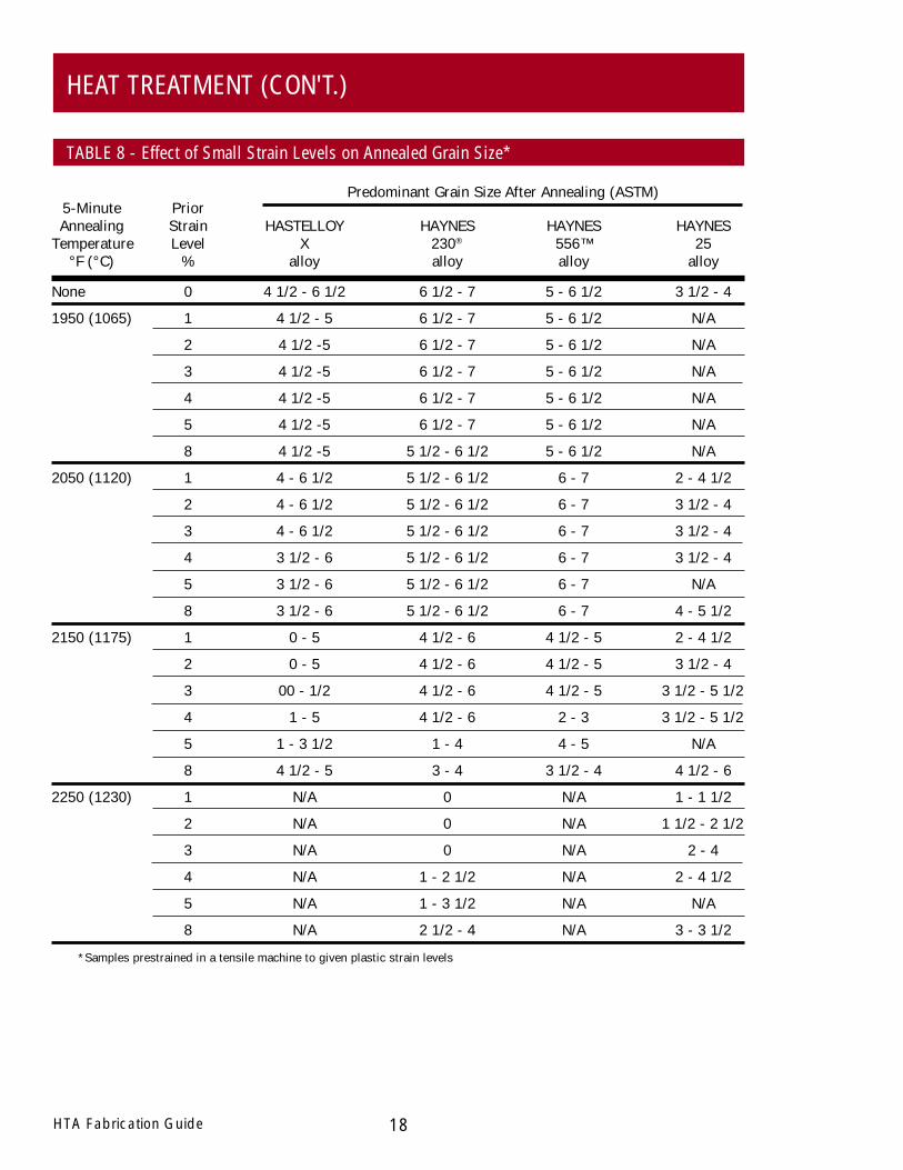
TABLE 8 - Effect of Small Strain Levels on Annealed Grain Size*
5-Minute PriorAnnealing Strain HASTELLOY HAYNES HAYNES HAYNES
Temperature Level X 230® 556™ 25°F (°C) % alloy alloy alloy alloy
None 0 4 1/2 - 6 1/2 6 1/2 - 7 5 - 6 1/2 3 1/2 - 4
1950 (1065) 1 4 1/2 - 5 6 1/2 - 7 5 - 6 1/2 N/A
2 4 1/2 -5 6 1/2 - 7 5 - 6 1/2 N/A
3 4 1/2 -5 6 1/2 - 7 5 - 6 1/2 N/A
4 4 1/2 -5 6 1/2 - 7 5 - 6 1/2 N/A
5 4 1/2 -5 6 1/2 - 7 5 - 6 1/2 N/A
8 4 1/2 -5 5 1/2 - 6 1/2 5 - 6 1/2 N/A
2050 (1120) 1 4 - 6 1/2 5 1/2 - 6 1/2 6 - 7 2 - 4 1/2
2 4 - 6 1/2 5 1/2 - 6 1/2 6 - 7 3 1/2 - 4
3 4 - 6 1/2 5 1/2 - 6 1/2 6 - 7 3 1/2 - 4
4 3 1/2 - 6 5 1/2 - 6 1/2 6 - 7 3 1/2 - 4
5 3 1/2 - 6 5 1/2 - 6 1/2 6 - 7 N/A
8 3 1/2 - 6 5 1/2 - 6 1/2 6 - 7 4 - 5 1/2
2150 (1175) 1 0 - 5 4 1/2 - 6 4 1/2 - 5 2 - 4 1/2
2 0 - 5 4 1/2 - 6 4 1/2 - 5 3 1/2 - 4
3 00 - 1/2 4 1/2 - 6 4 1/2 - 5 3 1/2 - 5 1/2
4 1 - 5 4 1/2 - 6 2 - 3 3 1/2 - 5 1/2
5 1 - 3 1/2 1 - 4 4 - 5 N/A
8 4 1/2 - 5 3 - 4 3 1/2 - 4 4 1/2 - 6
2250 (1230) 1 N/A 0 N/A 1 - 1 1/2
2 N/A 0 N/A 1 1/2 - 2 1/2
3 N/A 0 N/A 2 - 4
4 N/A 1 - 2 1/2 N/A 2 - 4 1/2
5 N/A 1 - 3 1/2 N/A N/A
8 N/A 2 1/2 - 4 N/A 3 - 3 1/2
*Samples prestrained in a tensile machine to given plastic strain levels
Predominant Grain Size After Annealing (ASTM)
19
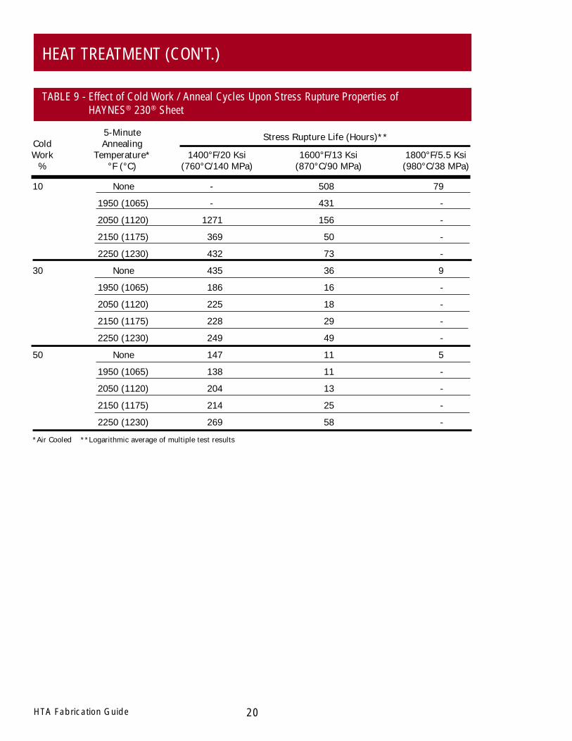
treatment or substitute a stressrelief anneal. This is of coursesubject to specification limita-tions. Depending upon theindividual alloy, and the serviceconditions under which thecomponent is to be used,leaving the material in theslightly-worked or stress-relieved condition can actuallyimprove some performancecharacteristics, such as creepstrength. This is illustrated forHAYNES 230® alloy by the datain Table 9. As each particularcase will be different, it isadvisable to contact HaynesInternational before deciding totake such an approach.
Where more than about 10percent cold work is present inthe piece, a final anneal isusually mandatory. Putting as-cold-worked material intoservice can result in recrystalli-zation to a very fine grain size,which in turn can produce asignificant reduction in stressrupture strength. This is alsoillustrated for 230 alloy by thedata in Table 9.
Solution heat treating (see page13) is the most common form offinishing operation applied toHAYNES® and HASTELLOY®
high-temperature alloys, and isoften mandated by the appli-cable specifications for thesematerials. Mill annealing (seepage 13) is required in somespecific cases, such as forGrade I alloy 625 but is lesscommonly used. Wherepermitted by relevant specifica-tions, it may be possible toadjust the final structure andproperties of the component byselecting a solution treatmenttemperature at the high or lowend of the allowable ranges, asgiven in Table 6. This is ofcourse dependent upon theamount of cold or warm workpresent in the piece prior toannealing.
In some cases, where only aminor amount of forming hasbeen done, and the amount ofdeformation in the piece is lessthan about 10 percent cold orwarm work, it may be advisableto omit a final solution heat
Unlike mill annealing, which isusually performed as a stepunto itself, solution treatingmay sometimes be combinedwith another operation whichimposes significant constraintsupon both heating and coolingpractices. A good example ofthis is vacuum brazing. Oftenperformed as the final step inthe fabrication of some compo-nents, such a process pre-cludes the possibility of asubsequent solution treatmentbecause of the low meltingpoint of the brazing com-pound. Consequently, theactual brazing temperaturesused are sometimes adjustedto allow for the simultaneoussolution heat treating of thecomponent. Since it is thenature of vacuum furnaces thatboth heating and cooling ratesare relatively slow, even withthe benefit of advanced gascooling equipment, it must berecognized that alloy structureand properties produced maybe less than optimum.
HTA Fabrication Guide
best, although this can makethe material subject to abnor-mal grain growth. At any rate,it should be recognized thatany treatment below thebottom of the solution treat-ment temperature range andabove about 1000°F (540°C)may promote grain boundarycarbide precipitation in thesealloys, with consequent effectsupon component properties.
or Ni-Cr alloys are generally noteffective for HAYNES andHASTELLOY high-temperaturealloys.
In many cases, stress relievingat mill annealing temperaturesabout 100 to 200°F (55 to110°C) above the intended usetemperature will provide goodresults. In other cases, a fullsolution anneal at the low endof the allowable range may be
A stress relief anneal should beconsidered as such only if thetreatment does not producerecrystallization in the material.Relief of residual stress in thesealloys, arising from thermalstrains produced by non-uniform cooling, or slightdeformations imparted duringsizing operations, is oftendifficult to achieve. Stress relieftemperatures commonly usedfor steels and simple Fe-Ni-Cr
STRESS RELIEVING
FINAL ANNEALING
HEAT TREATMENT (CON'T.)
20HTA Fabrication Guide
5-MinuteCold AnnealingWork Temperature* 1400°F/20 Ksi 1600°F/13 Ksi 1800°F/5.5 Ksi
% °F (°C) (760°C/140 MPa) (870°C/90 MPa) (980°C/38 MPa)
10 None - 508 79
1950 (1065) - 431 -
2050 (1120) 1271 156 -
2150 (1175) 369 50 -
2250 (1230) 432 73 -
30 None 435 36 9
1950 (1065) 186 16 -
2050 (1120) 225 18 -
2150 (1175) 228 29 -
2250 (1230) 249 49 -
50 None 147 11 5
1950 (1065) 138 11 -
2050 (1120) 204 13 -
2150 (1175) 214 25 -
2250 (1230) 269 58 -
*Air Cooled **Logarithmic average of multiple test results
Stress Rupture Life (Hours)**
HEAT TREATMENT (CON'T.)
TABLE 9 - Effect of Cold Work / Anneal Cycles Upon Stress Rupture Properties ofHAYNES® 230® Sheet
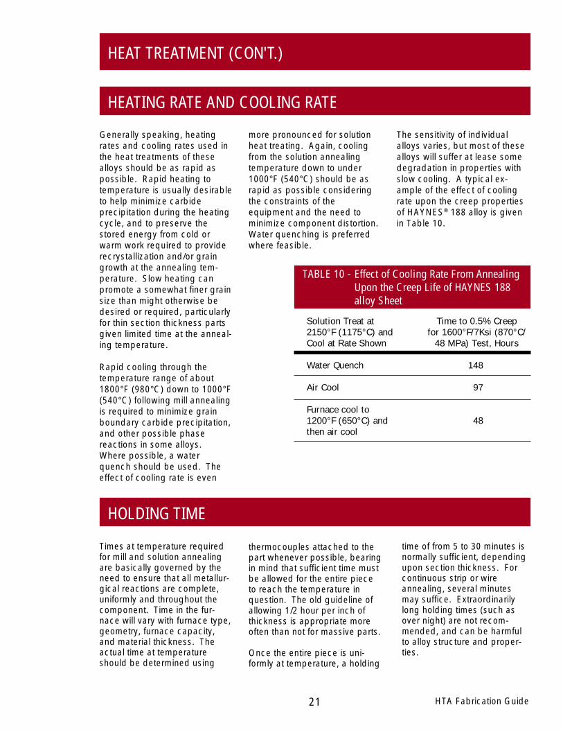
Solution Treat at Time to 0.5% Creep2150°F (1175°C) and for 1600°F/7Ksi (870°C/Cool at Rate Shown 48 MPa) Test, Hours
Water Quench 148
Air Cool 97
Furnace cool to1200°F (650°C) and 48then air cool
time of from 5 to 30 minutes isnormally sufficient, dependingupon section thickness. Forcontinuous strip or wireannealing, several minutesmay suffice. Extraordinarilylong holding times (such asover night) are not recom-mended, and can be harmfulto alloy structure and proper-ties.
thermocouples attached to thepart whenever possible, bearingin mind that sufficient time mustbe allowed for the entire pieceto reach the temperature inquestion. The old guideline ofallowing 1/2 hour per inch ofthickness is appropriate moreoften than not for massive parts.
Once the entire piece is uni-formly at temperature, a holding
Times at temperature requiredfor mill and solution annealingare basically governed by theneed to ensure that all metallur-gical reactions are complete,uniformly and throughout thecomponent. Time in the fur-nace will vary with furnace type,geometry, furnace capacity,and material thickness. Theactual time at temperatureshould be determined using
HTA Fabrication Guide21
HOLDING TIME
HEAT TREATMENT (CON'T.)
Generally speaking, heatingrates and cooling rates used inthe heat treatments of thesealloys should be as rapid aspossible. Rapid heating totemperature is usually desirableto help minimize carbideprecipitation during the heatingcycle, and to preserve thestored energy from cold orwarm work required to providerecrystallization and/or graingrowth at the annealing tem-perature. Slow heating canpromote a somewhat finer grainsize than might otherwise bedesired or required, particularlyfor thin section thickness partsgiven limited time at the anneal-ing temperature.
Rapid cooling through thetemperature range of about1800°F (980°C) down to 1000°F(540°C) following mill annealingis required to minimize grainboundary carbide precipitation,and other possible phasereactions in some alloys.Where possible, a waterquench should be used. Theeffect of cooling rate is even
TABLE 10 - Effect of Cooling Rate From AnnealingUpon the Creep Life of HAYNES 188alloy Sheet
HEATING RATE AND COOLING RATE
more pronounced for solutionheat treating. Again, coolingfrom the solution annealingtemperature down to under1000°F (540°C) should be asrapid as possible consideringthe constraints of theequipment and the need tominimize component distortion.Water quenching is preferredwhere feasible.
The sensitivity of individualalloys varies, but most of thesealloys will suffer at lease somedegradation in properties withslow cooling. A typical ex-ample of the effect of coolingrate upon the creep propertiesof HAYNES® 188 alloy is givenin Table 10.
22HTA Fabrication Guide
USE OF PROTECTIVE ATMOSPHERE
Annealing in nitrogen orcracked ammonia is notgenerally preferred, but maybe acceptable in some cases.
Vacuum annealing is generallyacceptable, but may alsoproduce some tinting depend-ing upon the equipment andtemperature. Selection of thegas used for forced gascooling can also influenceresults. Helium is normallypreferred, followed by argonand nitrogen (in some cases).
in neutral to slightly reducingenvironments.
Protective atmosphere anneal-ing is commonly performed forall of these materials when abright finish is desired. The bestchoice for annealing of this typeis a low-dew-point hydrogenenvironment. Annealing mayalso be done in argon andhelium, although more pro-nounced tinting from oxygen orwater vapor contamination issometimes encountered.
Most of these alloys may beannealed in oxidizing environ-ments, but will form adherentoxide scales which normallymust be removed prior tofurther processing. For detailson scale removal, please seethe DESCALING AND PICK-LING section of this guide.Some HAYNES® andHASTELLOY® high-temperaturealloys contain low chromiumcontents (see page 5, Table 1).Atmosphere annealing of thesematerials should be performed
and the like is not acceptable.Flame impingement of anytype during heat treatment is tobe avoided.
control of temperature andtemperature uniformity is ofteninadequate. Heating bytorches, welding equipment
Most industrial furnace typesare suitable for heat treatingthese alloys. Induction heatingis generally not preferred, as
SELECTION OF HEAT TREATING EQUIPMENT
HEAT TREATMENT (CON'T.)
HTA Fabrication Guide23
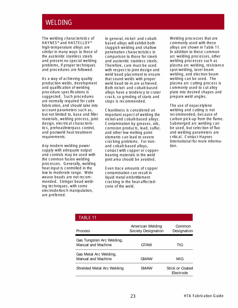
Welding processes that arecommonly used with thesealloys are shown in Table 11.In addition to these commonarc welding processes, otherwelding processes such asplasma arc welding, resistancespot welding, laser beamwelding, and electron beamwelding can be used. Theplasma arc cutting process iscommonly used to cut alloyplate into desired shapes andprepare weld angles.
The use of oxyacetylenewelding and cutting is notrecommended, because ofcarbon pick-up from the flame.Submerged arc welding canbe used, but selection of fluxand welding parameters arecritical. Contact HaynesInternational for more informa-tion.
In general, nickel- and cobalt-based alloys will exhibit bothsluggish welding and shallowpenetration characteristics incomparison to those for steelsand austenitic stainless steels.Therefore, care must be usedwith respect to joint design andweld bead placement to ensurethat sound welds with properweld bead tie-in are achieved.Both nickel- and cobalt-basedalloys have a tendency to cratercrack, so grinding of starts andstops is recommended.
Cleanliness is considered animportant aspect of welding thenickel-and cobalt-based alloys.Contamination by greases, oils,corrosion products, lead, sulfur,and other low melting pointelements can lead to severecracking problems. For iron-and cobalt-based alloys,contact with copper or copper-bearing materials in the weldjoint area should be avoided.
Even trace amounts of coppercontamination can result inliquid metal embrittlementcracking in the heat-affected-zone of the weld.
The welding characteristics ofHAYNES® and HASTELLOY®
high-temperature alloys aresimilar in many ways to those ofthe austenitic stainless steelsand present no special weldingproblems, if proper techniquesand procedures are followed.
As a way of achieving qualityproduction welds, developmentand qualification of weldingprocedure specifications issuggested. Such proceduresare normally required for codefabrication, and should take intoaccount parameters such as,but not limited to, base and fillermaterials, welding process, jointdesign, electrical characteris-tics, preheat/interpass control,and postweld heat treatmentrequirements.
Any modern welding powersupply with adequate outputand controls may be used withthe common fusion weldingprocesses. Generally, weldingheat input is controlled in thelow to moderate range. Wideweave beads are not recom-mended. Stringer bead weld-ing techniques, with someelectrode/torch manipulation,are preferred.
American Welding CommonProcess Society Designation Designation
Gas Tungsten Arc Welding,Manual and Machine GTAW TIG
Gas Metal Arc Welding,Manual and Machine GMAW MIG
Shielded Metal Arc Welding SMAW Stick or CoatedElectrode
WELDING
TABLE 11

24HTA Fabrication Guide
Where dissimilar metal weldsare involved, selection of thewelding filler metal dependsupon the specific circum-stances. One, both or neitherof the two alloys in questionmay be suitable for the fillermetal. Some filler wire alloyssupplied by Haynes Interna-tional are suitable for a broadspectrum of dissimilar weldingapplications. These includeHASTELLOY S and W alloys ,as well as HAYNES 25, 556™,and 230-W™ alloys.
preferred. For heavy sectionthicknesses (>1/2 in.), a spe-cially formulated version of thebase metal composition, or evena completely dissimilar alloy,may be an appropriate fillermetal selection to avoid hotcracking in certain alloys, suchas HAYNES HR-160® alloy. Thisis particularly important underconditions of heavy restraint. Insome instances, a completelydissimilar alloy is the recom-mended selection in all cases,such as for HAYNES HR-120®
alloy.
Selection of the correct weldingfiller wire for welded jointconstruction of HAYNES® andHASTELLOY® high-temperaturealloys is extremely important.The criteria applied to theselection include not only theease of welding, but also thesoundness and in-serviceperformance characteristics ofthe weldment as well. This isequally true for selectingwelding filler wire for dissimilarmetal joining applications.
For matching material welds,selection of a matching compo-sition filler wire is generally
Designation Description AWS A5.14 AWS A5.11 AMS*
1 HASTELLOY S alloy - - 5838
2 HASTELLOY W alloy ER NiMo-3 E NiMo-3 5786, 5787*
3 HASTELLOY X alloy ER NiCrMo-2 E NiCrMo-2 5798, 5799*
4 HAYNES 25 alloy - - 5796, 5797*
6 HAYNES 188 alloy - - 5801
7 HAYNES R-41 alloy - - 5800
8 HAYNES HR-160® alloy - - -
9 HAYNES 214™ alloy - - -
10 HAYNES 230® alloy - - -
11 230-W™ Filler Wire ER NiCrWMo-1 - 5839
12 HAYNES 242™ alloy - - -
13 HAYNES 263 alloy - - -
14 HAYNES 556™ alloy A5.9 ER 3556 - 5831
15 HAYNES 625 alloy ER NiCrMo-3 E NiCrMo-3 5837
16 HAYNES 718 alloy ER NiFeCr-2 - 5832
17 MULTIMET® alloy - - 5794, 5795*
18 WASPALOY alloy - - 5828
*Second number is for coated electrodes
WELDING (CON'T.)
SELECTION OF WELDING FILLER METAL
TABLE 12 - Haynes International Filler Metal Alloys
HTA Fabrication Guide25
forms for specific alloys.Available forms for HaynesInternational welding productsare listed in Table 15.
Information on filler metalselection for precipitation-strengthened alloys, in addi-tion to that for solid-solution-strengthened materials, hasbeen presented here for thesake of completeness. Theformer alloys fall outside thescope of this guide, and theother sections of this publica-tion will generally not apply tosuch materials. Please contactHaynes International for furtherinformation.
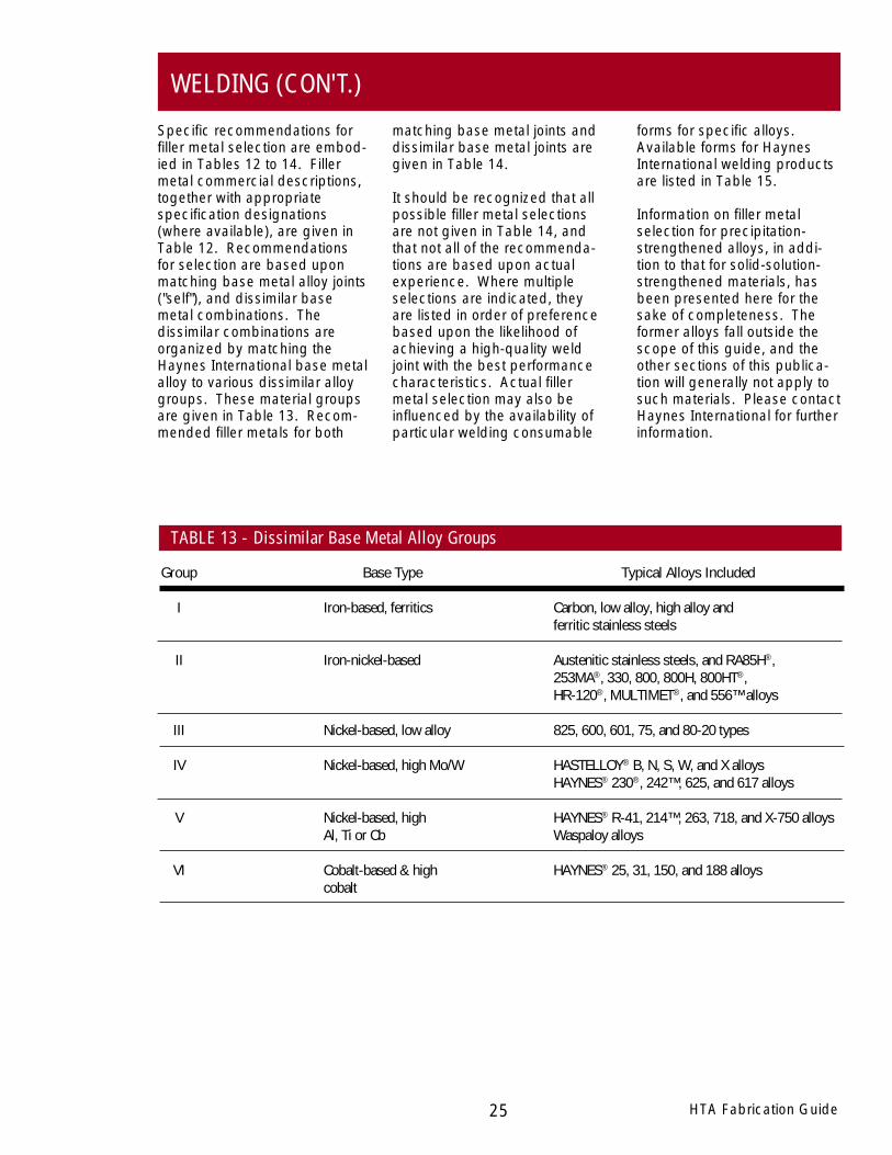
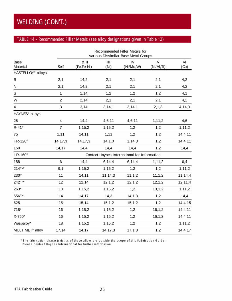
Specific recommendations forfiller metal selection are embod-ied in Tables 12 to 14. Fillermetal commercial descriptions,together with appropriatespecification designations(where available), are given inTable 12. Recommendationsfor selection are based uponmatching base metal alloy joints("self"), and dissimilar basemetal combinations. Thedissimilar combinations areorganized by matching theHaynes International base metalalloy to various dissimilar alloygroups. These material groupsare given in Table 13. Recom-mended filler metals for both
matching base metal joints anddissimilar base metal joints aregiven in Table 14.
It should be recognized that allpossible filler metal selectionsare not given in Table 14, andthat not all of the recommenda-tions are based upon actualexperience. Where multipleselections are indicated, theyare listed in order of preferencebased upon the likelihood ofachieving a high-quality weldjoint with the best performancecharacteristics. Actual fillermetal selection may also beinfluenced by the availability ofparticular welding consumable
Group Base Type Typical Alloys Included
I Iron-based, ferritics Carbon, low alloy, high alloy andferritic stainless steels
II Iron-nickel-based Austenitic stainless steels, and RA85H®,253MA®, 330, 800, 800H, 800HT®,HR-120®, MULTIMET®, and 556™ alloys
III Nickel-based, low alloy 825, 600, 601, 75, and 80-20 types
IV Nickel-based, high Mo/W HASTELLOY® B, N, S, W, and X alloysHAYNES® 230®, 242™, 625, and 617 alloys
V Nickel-based, high HAYNES® R-41, 214™, 263, 718, and X-750 alloysAl, Ti or Cb Waspaloy alloys
VI Cobalt-based & high HAYNES® 25, 31, 150, and 188 alloyscobalt
TABLE 13 - Dissimilar Base Metal Alloy Groups
WELDING (CON'T.)
Base I & II III IV V VIMaterial Self (Fe,Fe-Ni) (Ni) (Ni/Mo,W) (Ni/Al,Ti) (Co)
HASTELLOY® alloys
B 2,1 14,2 2,1 2,1 2,1 4,2
N 2,1 14,2 2,1 2,1 2,1 4,2
S 1 1,14 1,2 1,2 1,2 4,1
W 2 2,14 2,1 2,1 2,1 4,2
X 3 3,14 3,14,1 3,14,1 2,1,3 4,14,3
HAYNES® alloys
25 4 14,4 4,6,11 4,6,11 1,11,2 4,6
R-41* 7 1,15,2 1,15,2 1,2 1,2 1,11,2
75 1,11 14,11 1,11 1,2 1,2 14,4,11
HR-120® 14,17,3 14,17,3 14,1,3 1,14,3 1,2 14,4,11
150 14,17 14,4 14,4 14,4 1,2 14,4
HR-160® Contact Haynes International for Information
188 6 14,4 6,14,4 6,14,4 1,11,2 6,4
214™* 9,1 1,15,2 1,15,2 1,2 1,2 1,11,2
230® 11 14,11 11,14,3 11,1,2 11,1,2 11,14,4
242™* 12 12,14 12,1,2 12,1,2 12,1,2 12,11,4
263* 13 1,15,2 1,15,2 1,2 13,1,2 1,11,2
556™ 14 14,17 14,3 14,1,3 1,2 14,4
625 15 15,14 15,1,2 15,1,2 1,2 14,4,15
718* 16 1,15,2 1,15,2 1,2 16,1,2 14,4,11
X-750* 16 1,15,2 1,15,2 1,2 16,1,2 14,4,11
Waspaloy* 18 1,15,2 1,15,2 1,2 1,2 1,11,2
MULTIMET® alloy 17,14 14,17 14,17,3 17,1,3 1,2 14,4,17
* The fabrication characteristics of these alloys are outside the scope of this Fabrication Guide. Please contact Haynes International for further information.
26HTA Fabrication Guide
WELDING (CON'T.)
TABLE 14 - Recommended Filler Metals (see alloy designations given in Table 12)
Recommended Filler Metals forVarious Dissimilar Base Metal Groups

HTA Fabrication Guide27
WELDING (CON'T.)
TABLE 15 - Available Forms for Haynes International Filler Metals
single-groove (Joint II) whereaccess to only one side of thejoint is possible. The remain-der of the joint can then befilled using other weldingprocesses as appropriate. Forgroove welds on heavy sectionplates greater than 3/4 inch(19 mm) thick, a J-groove ispermissible. Such a jointreduces the amount of fillermetal and time required tocomplete the weld. Othertypical welding joint designsare shown in Figure 7. Theactual number of passesrequired to fill the joint de-pends upon a number offactors that include the filler
Preparation. In addition, fabri-cation codes such as the ASMEPressure Vessel and PipingCode may impose designrequirements.
Typical butt joint designs thatare used with the gas tungstenarc welding (GTAW), gas metalarc welding (GMAW), andshielded metal arc welding(SMAW) processes are (I)Square-Groove, (II) Single-V-Groove, and (III) Double-V-Groove shown in Figure 6. Gastungsten arc welding is often thepreferred method for depositingthe root pass associated withthe square-groove (Joint I) or
Selection of a correct weld jointdesign is critical to the success-ful fabrication of HAYNES andHASTELLOY high-temperaturealloys. Poor joint design cannegate even the most optimumselection of welding filler metal.
Various welding documents areavailable to assist in the designof welded joints. Two suchdocuments that provide guid-ance are American WeldingSociety, Welding Handbook,Volume 1, Eighth Edition,Chapter 5 and ASM Interna-tional, Metals Handbook,Volume 6, Welding, Brazing andSoldering, Joint Design and
WELD JOINT DESIGN
Straight Layer Wound Coated LooseFiller Material Lengths1 Spools2,3 Electrodes4 Coils5
HASTELLOY® W and X alloys; HAYNES®
25 alloy; 230-W™ filler wire; Yes Yes Yes YesMULTIMET® alloy
HASTELLOY S alloy; HAYNESR-41, 188, 263, 625 and 718 alloys; Yes Yes No YesWaspaloy alloy; 214™, 230-W™,242™, 556™, and HR-160® alloys.
1 36-inch (0.9 m) length standard; 0.035, 0.045, 0.062, 0.094, and 0.125-inch (0.9, 1.1, 1.6, 2.4, and 3.2 mm)diameter standard. Other sizes available upon request.
2 25 pound (11.4 kg) standard coil; 0.035, 0.045 and 0.062-inch (0.9, 1.1 and 1.6 mm) diameter standard. Othersizes available upon request.
3 10 pound (4.5 kg) spools available in selected alloys, such as 230-W filler wire and 214 alloy.
4 14-inch (0.36 m) standard length for 0.125 and 0.156-inch (3.2 and 4.0 mm) diameters. 9-inch (0.23 m) lengthstandard for 0.094-inch (2.4 mm) diameter.
5 50 pound (22.7 kg) minimum coils; 0.035 to 0.187-inch (0.9 to 4.8 mm) diameters.

28HTA Fabrication Guide
WELDING (CON'T.)
electrode manipulation andplacement of the weld bead.
A general estimate of fillermetal requirements is aboutfour to five percent (by weight)of the base plate requirement.Estimated weight of weld metalrequired per unit length ofwelding is given in Table 16.
place the molten metal whereneeded. In addition to thesluggishness, the joint penetra-tion is also less than that of atypical carbon or stainless steelweld. With this low penetrationpattern, the possibility of incom-plete fusion increases. As aresult of these factors, care mustbe taken to insure that thegroove opening is wide enoughto allow proper torch or
metal size (electrode or wirediameter), the amperage, andthe travel speed.
It should be recognized thatnickel- and cobalt-based alloyweld metal is sluggish (not asfluid as carbon steel) and doesnot flow out as readily and "wet"the sidewalls. Therefore, thewelding arc and filler metalmust be manipulated so as to
WELD JOINT DESIGN (CON'T.)
TABLE 16
Included Approx. WeightMaterial Preferred Root Land Weld of Weld MetalThickness (t), Joint Opening (A), Thickness (B) Angle (C), Required,in. (mm) Design in (mm) in (mm) degrees lbs/ft (kg/m)
1/16 (1.6) l 0-1/16 (0-1.6) N/A None 0.02 (0.03)
3/32 (2.4) I 0-3/32 (0-2.4) N/A None 0.04 (0.06)
1/8 (3.2) I 0-1/8 (0-3.2) N/A None 0.06 (0.09)
1/4 (6.3) II 1/16-1/8 (1.6-3.2) 60-75 0.30 (0.45)
3/8 (9.5) II 60-75 0.60 (0.89)
1/2 (12.7) II 60-75 0.95 (1.41)
1/2 (12.7) III 1/32-5/32 1/32-3/32 60-75 0.60 (0.89)
5/8 (15.9) II (0.8-4.0) (0.8-2.4) 60-75 1.40 (2.08)
5/8 (15.9) III 60-75 0.82 (1.22)
3/4 (19.1) II 60-75 1.90 (2.83)
3/4 (19.1) III 60-75 1.20 (1.79)
Figure 6Typical Butt Joints for Manual Welding
HTA Fabrication Guide29
WELDING (CON'T.)
Stainless steel wire brushing isnormally sufficient for interpasscleaning of GTAW and GMAWweldments. The grinding ofstarts and stops is recom-mended for all fusion weldingprocesses. If oxygen orcarbon dioxide bearingshielding gases are usedduring gas metal arc welding,light grinding is necessarybetween passes prior to wirebrushing. Slag removal duringshielded metal arc welding willrequire chipping and grindingfollowed by wire brushing.
In addition to the weld angle, a 1inch (25 mm) wide band on thetop and bottom (face and root)surface of the weld zone shouldbe conditioned to bright metalwith about an 80 grit flapperwheel or disk.
The welding surface andadjacent regions should bethoroughly cleaned with anappropriate solvent prior to anywelding operation. All greases,oils, cutting oils, crayon marks,machining solutions, corrosionproducts, paint, scale, dyepenetrant solutions, and otherforeign matter should be com-pletely removed.
Proper preparation of the weldjoint region is a very importantpart of the welding of nickel-and cobalt-based alloys. Avariety of mechanical andthermal cutting methods areavailable for the preparation ofweld angles. Plasma cutting/gouging, machining, grinding,and air arc gouging are allpotential processes. It isnecessary to condition allthermal cut edges to bright,shiny metal prior to welding.(This is particularly important ifair arc gouging is being useddue to the extreme possibility ofcarbon pick-up from the carbonelectrode.)
CLEANING, EDGE PREPARATION AND FIT-UP
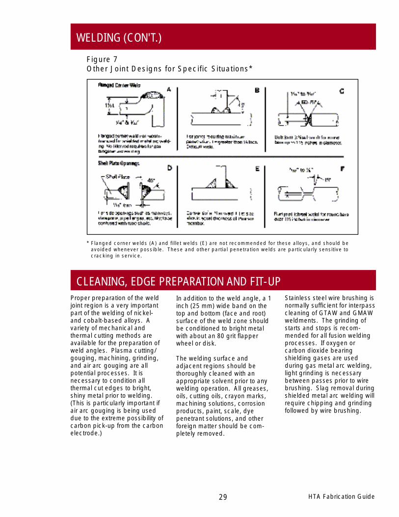
Figure 7Other Joint Designs for Specific Situations*
* Flanged corner welds (A) and fillet welds (E) are not recommended for these alloys, and should beavoided whenever possible. These and other partial penetration welds are particularly sensitive tocracking in service.
30HTA Fabrication Guide
WELDING (CON'T.)
temperature. Water quenchingis acceptable. Care must betaken so that the weld zone isnot contaminated with tracesof oil from shop air lines,grease/dirt from soiled water-soaked rags or mineral depos-its from hard water used tocool the weld joint. The safestway to maintain a low interpasstemperature is to allow theassembly to cool naturally.When attaching hardware tothe outside of a thin-walledvessel, it is good practice toprovide auxiliary cooling to theinside (process side) tominimize the extent of the heat-affected-zone.
heating if possible (infraredheaters or natural heating toroom temperature).
If oxyacetylene warming is used,the heat should be appliedevenly over the base metalrather than in the weld zone.The torch should be adjusted sothat the flame is not carburizing.A "rosebud" tip, which distrib-utes the flame evenly, is recom-mended. Care should be takento avoid local or incipientmelting as a result of the warm-ing process.
Auxiliary cooling methods maybe used to control the interpass
Preheating of HAYNES® andHASTELLOY® corrosion andheat-resistant alloys is notrequired. Preheat is generallyspecified as room temperature(typical shop conditions).Interpass temperature shouldbe maintained below 200°F(93°C).
The alloy base plate mayrequire warming to raise thetemperature above freezing orto prevent condensation ofmoisture. Condensation mayoccur if the alloy is brought intoa warm shop from cold outdoorstorage. Warming should beaccomplished by indirect
PREHEAT, INTERPASS TEMPERATURES, AND COOLING TECHNIQUES
selection of an appropriateheat treatment will be gov-erned by the various criteriadiscussed in the HEAT TREAT-MENT section of this guide.
proper weldment performance.Heat treatment of weldedfabrications may be required forother reasons, such as stressrelief. In these cases, the
Postweld heat treatment ofHAYNES and HASTELLOYsolid-solution-strengthenedhigh-temperature alloys is notgenerally required to assure
POSTWELD HEAT TREATMENT
defects have been removed,and then thoroughly cleanedprior to welding repair. Be-cause these alloys have lowpenetration characteristics, theground cavity must be broadenough and have sufficientsidewall clearance in the weldgroove to allow weld rod/weldbead manipulation. "Healingcracks" or "washing out"defects by autogenouslyremelting weld beads or bydepositing additional fillermetal over the defect is notrecommended.
Welding defects that are be-lieved to affect quality or me-chanical integrity should beremoved and weld-repaired.Removal techniques includegrinding, plasma arc gouging,and carbon arc gouging.Extreme care must be usedduring carbon arc gouging toinsure that carbon contamina-tion of the weld zone does notoccur.
Generally the prepared cavity isdye penetrant inspected toinsure that all objectionable
Good manufacturing practicesuggests that some degree ofnondestructive testing (NDT) beconducted. For code fabrica-tions, certain mandatory NDTinspections may be required.For non-code fabrication, NDTmay be as simple as visualinspection or dye penetrantinspection. NDT should beconsidered for both intermedi-ate quality control inspectionsduring fabrication, as well as forfinal acceptance tests.
INSPECTION AND REPAIR
HTA Fabrication Guide31
WELDING (CON'T.)
CONTROL OF DISTORTIONmakes the welding operationeasier and minimizes bucklingand warping of thin sections.
It is suggested that, wherepossible, extra stock be addedto the overall width and length.Excess material can then beremoved to obtain final dimen-sions.
Jigs, fixturing, cross supports,bracing, and bead placement/weld sequence will help to holddistortion to a minimum. Wherepossible, balanced weldingabout the neutral axis will assistin keeping distortion to a mini-mum. Proper fixturing andclamping of the assembly
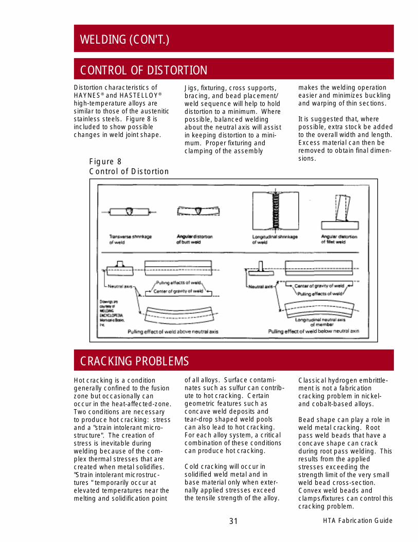
Distortion characteristics ofHAYNES® and HASTELLOY®
high-temperature alloys aresimilar to those of the austeniticstainless steels. Figure 8 isincluded to show possiblechanges in weld joint shape.
CRACKING PROBLEMSof all alloys. Surface contami-nates such as sulfur can contrib-ute to hot cracking. Certaingeometric features such asconcave weld deposits andtear-drop shaped weld poolscan also lead to hot cracking.For each alloy system, a criticalcombination of these conditionscan produce hot cracking.
Cold cracking will occur insolidified weld metal and inbase material only when exter-nally applied stresses exceedthe tensile strength of the alloy.
Classical hydrogen embrittle-ment is not a fabricationcracking problem in nickel-and cobalt-based alloys.
Bead shape can play a role inweld metal cracking. Rootpass weld beads that have aconcave shape can crackduring root pass welding. Thisresults from the appliedstresses exceeding thestrength limit of the very smallweld bead cross-section.Convex weld beads andclamps/fixtures can control thiscracking problem.
Hot cracking is a conditiongenerally confined to the fusionzone but occasionally canoccur in the heat-affected-zone.Two conditions are necessaryto produce hot cracking: stressand a "strain intolerant micro-structure". The creation ofstress is inevitable duringwelding because of the com-plex thermal stresses that arecreated when metal solidifies."Strain intolerant microstruc-tures " temporarily occur atelevated temperatures near themelting and solidification point
Figure 8Control of Distortion

WELDING (CON'T.)
are used in high travel speed,highly mechanized weldingsystems.
In addition to welding torchshielding gas, a back-purge atthe root side of the weld joint isrecommended (welding gradeargon). The flow rates arenormally in the 5 to 10 cubicfeet per hour range. Oftenbacking bars (usually copper)are used to assist in beadshape on the root side ofGTAW welds. Backing gas isoften introduced though smallholes along the length of thebacking bar.
There are situations wherebacking bars cannot be used.Under these conditions, open-butt welding is often per-formed. Such welding condi-tions are often encounteredduring pipe or tube circumfer-ential butt welding. Underthese conditions where accessto the root side of the joint isnot possible, special gas flowconditions have been estab-lished which differ from theindustry recommendationspublished elsewhere. Underthese open-butt weldingconditions, the torch flow rates
presented in Table 17. Electri-cal polarity should be directcurrent electrode negative(DCEN).
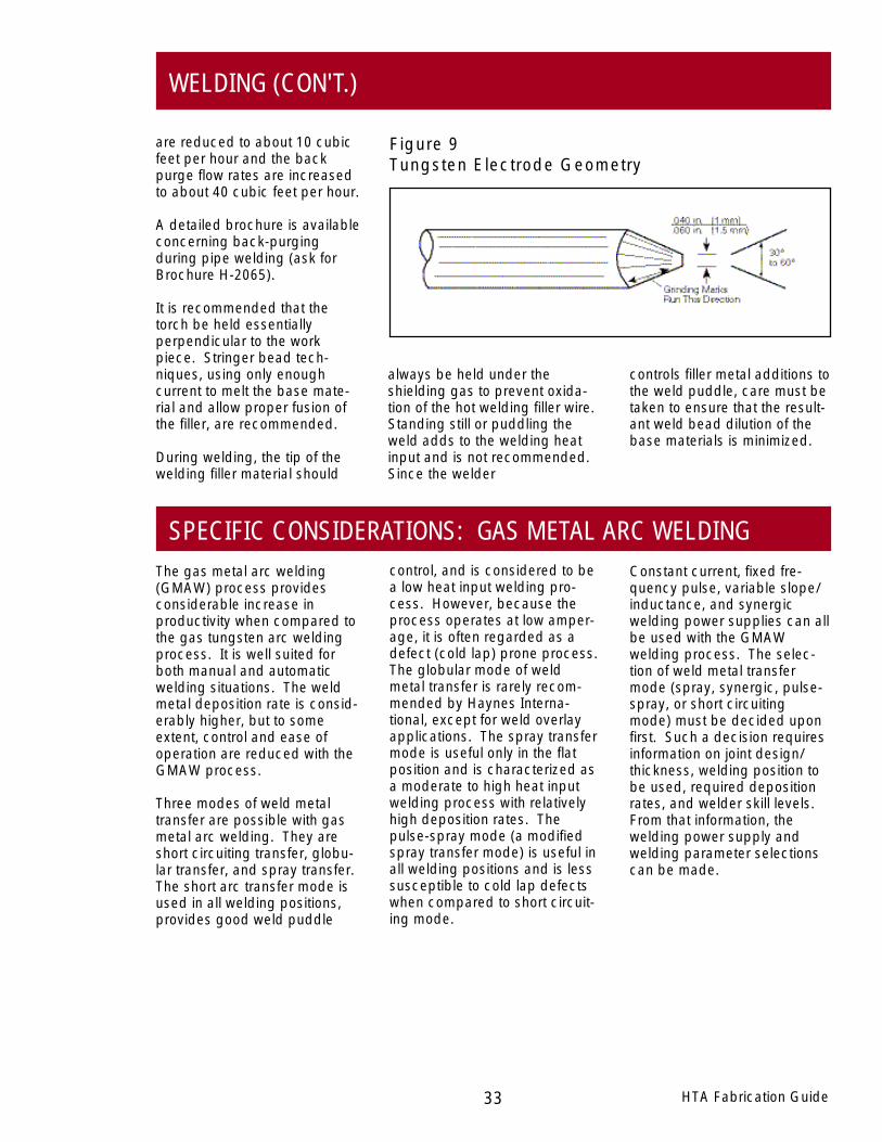
Two percent thoriated tungstenelectrodes are recommended.The classification for theseelectrodes is EWTh-2 (AmericanWelding Society SpecificationA5.12). The diameter of thetungsten electrode will vary withamperage. General recommen-dations for electrode diameterselection are given in Table 17.It is recommended that theelectrode be ground to a coneshape (included angle of 30 to60 degrees) with a small 1/16inch (1.6 mm) flat ground at thepoint. See Figure 9 for details.
Welding grade argon (99.996percent minimum purity) shield-ing gas is recommended for allnormal fabrication situations.The flow rates are normally inthe 25-30 cubic feet per hourrange. When proper shielding isachieved, the as-deposited weldmetal should have a bright-shinyappearance and require onlyminor wire brushing betweenpasses. On special occasions,argon-helium or argon-hydrogenshielding gases
The gas tungsten arc welding(GTAW) process is a veryversatile, all-position weldingprocess. It can be used inproduction as well as repairsituations. It can be usedmanually or adapted to auto-matic equipment to weld thinsheet or plate material. It is aprocess that offers great controland is therefore routinely usedduring tack welding and rootpass welding. The majordrawback of the process isproductivity. For manualwelding situations, GTAW weldmetal deposition rates are low.
Generally, power suppliesequipped with high-frequencystart, pre-purge/post-purge andup-slope/down-slope (or footpeddle) controls are recom-mended. It is recommendedthat the GTAW welding torch beequipped with a gas diffuserscreen ("gas lens") to provideoptimum shielding gas cover-age. Generally, the gas cupshould be as large as practical.
Typical welding parameters,which are suggested for theHAYNES® and HASTELLOY®
high-temperature alloys, are
SPECIFIC CONSIDERATIONS: GAS TUNGSTEN ARC WELDING
32HTA Fabrication Guide
TungstenElectrode Filler Wire Welding
Joint Thickness Diameter Diameter Currentin (mm) in (mm) in (mm) Amps Volts
0.030-0.063 (0.8-1.6) 0.063 (1.6) 0.063 (1.6) 15-60 9-12
0.063-0.125 (1.6-3.2) 0.063/0.094 (1.6/2.4) 0.063/0.094 (1.6/2.4) 50-95 9-12
0.125-0.250 (3.2-6.3) 0.094/0.125 (2.4/3.2) 0.094/0.125 (2.4/3.2) 75-150 10-13
0.250 (6.3) and up 0.094/0.125 (2.4/3.2) 0.094/0.125 (2.4/3.2) 95-200 10-13
* DCEN
TABLE 17 - Typical Manual Gas Tungsten Arc Parameters (Flat Position)*
HTA Fabrication Guide33
WELDING (CON'T.)
are reduced to about 10 cubicfeet per hour and the backpurge flow rates are increasedto about 40 cubic feet per hour.
A detailed brochure is availableconcerning back-purgingduring pipe welding (ask forBrochure H-2065).
It is recommended that thetorch be held essentiallyperpendicular to the workpiece. Stringer bead tech-niques, using only enoughcurrent to melt the base mate-rial and allow proper fusion ofthe filler, are recommended.
During welding, the tip of thewelding filler material should
SPECIFIC CONSIDERATIONS: GAS METAL ARC WELDINGcontrol, and is considered to bea low heat input welding pro-cess. However, because theprocess operates at low amper-age, it is often regarded as adefect (cold lap) prone process.The globular mode of weldmetal transfer is rarely recom-mended by Haynes Interna-tional, except for weld overlayapplications. The spray transfermode is useful only in the flatposition and is characterized asa moderate to high heat inputwelding process with relativelyhigh deposition rates. Thepulse-spray mode (a modifiedspray transfer mode) is useful inall welding positions and is lesssusceptible to cold lap defectswhen compared to short circuit-ing mode.
Constant current, fixed fre-quency pulse, variable slope/inductance, and synergicwelding power supplies can allbe used with the GMAWwelding process. The selec-tion of weld metal transfermode (spray, synergic, pulse-spray, or short circuitingmode) must be decided uponfirst. Such a decision requiresinformation on joint design/thickness, welding position tobe used, required depositionrates, and welder skill levels.From that information, thewelding power supply andwelding parameter selectionscan be made.
The gas metal arc welding(GMAW) process providesconsiderable increase inproductivity when compared tothe gas tungsten arc weldingprocess. It is well suited forboth manual and automaticwelding situations. The weldmetal deposition rate is consid-erably higher, but to someextent, control and ease ofoperation are reduced with theGMAW process.
Three modes of weld metaltransfer are possible with gasmetal arc welding. They areshort circuiting transfer, globu-lar transfer, and spray transfer.The short arc transfer mode isused in all welding positions,provides good weld puddle
Figure 9Tungsten Electrode Geometry
always be held under theshielding gas to prevent oxida-tion of the hot welding filler wire.Standing still or puddling theweld adds to the welding heatinput and is not recommended.Since the welder
controls filler metal additions tothe weld puddle, care must betaken to ensure that the result-ant weld bead dilution of thebase materials is minimized.
WELDING (CON'T.)
synergic welding, a water-cooled torch is recommendedwhen current exceeds approxi-mately 120 amps.
As with gas tungsten arcwelding, back-purging isrequired to insure the root sideof the weld joint is not heavilyoxidized. As an alternative,many fabricators weld withoutback-purge shielding. Theythen grind the root side afterwelding to remove all oxidizedweld metal and defects, dyepenetrant check the weld zoneand then fill the weld joint fromboth sides as needed.
It should be recognized thatthe filler wire conduit linerassembly and contact tips(part of the GMAW weldingtorch) are high wear items andshould be expected to bereplaced periodically. Wear ofthe liner occurs as a result ofgalling between the carbonsteel liner and the alloy fillerwire. A worn liner will causeerratic wire feed which willresult in arc instability. Somewelding torches can be fittedwith a nylon conduit liner.Such a liner would be ex-pected to reduce wear andthus increase conduit life.
It is recommended that sharpbends in the GMAW torchcable be minimized. If pos-sible, move the wire feeder sothat the torch cable is nearlystraight during welding.
excellent out-of-position charac-teristics and excellent alloy-to-carbon steel welding character-istics. However, becausecarbon dioxide is present, theweld metal surface will be highlyoxidized. This oxidized conditioncan increase the possibility oflack-of-fusion defects. It istherefore strongly recom-mended that multipass welds,made with CO2 containinggases, be lightly ground be-tween passes to remove theoxidized surface.
The use of Ar+He in the shortcircuit mode is characterized bysome spatter and some degreeof arc instability when comparedto welds made with CO2 bearinggases. Because this shieldinggas is inert, the surface isexpected to be bright and shinywith minimal oxidation. Duringmultipass welding, it is notmandatory to grind betweenpasses. This situation alsoapplies to the other modes ofweld metal transfer when usingAr+He shielding gas.
In spray transfer welding, eventhough 100 percent argonshielding gas is used, someoxidation and "soot" may benoted on the weld surface.Heavy wire brushing and/or lightgrinding/conditioning (80 grit)between passes is recom-mended.
During spray transfer welding, awater-cooled welding torch isalways recommended. During
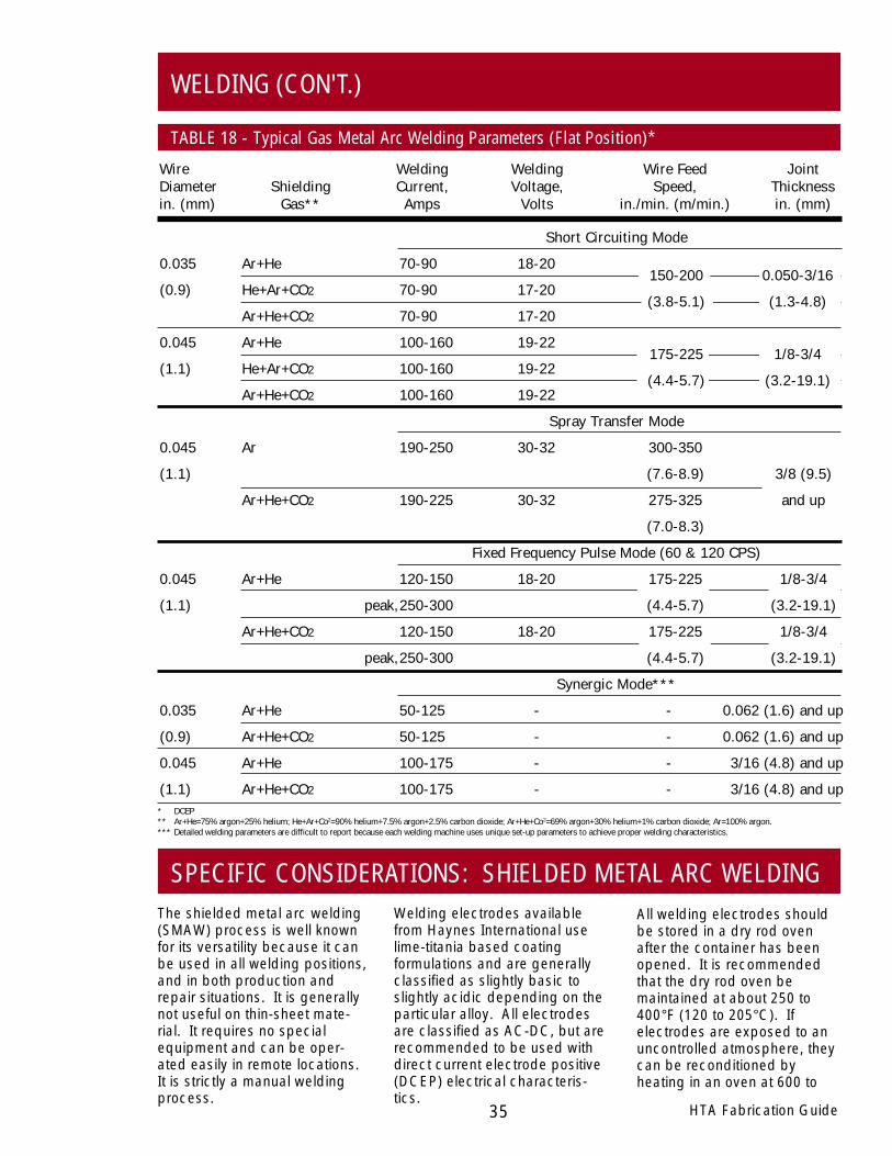
Typical welding parameters, forthe various weld metal transfermodes, are documented inTable 18. Electrical polarity isdirect current electrode positive(DCEP).
Shielding gas selection iscritical during GMAW proce-dure development. Fivewelding grade shielding gasesare suggested for the HAYNES®
and HASTELLOY® alloys. Thosegases are 75 percent argon +25 percent helium (Ar+He), 90percent helium + 7.5 percentargon + 2.5 percent carbondioxide (He+Ar+CO2), 66.1percent argon + 33 percenthelium + 0.9 percent carbondioxide (Ar+He+CO2), a propri-etary argon-helium-carbondioide mixture known asNiCoBRITE™ gas, and 100percent argon (Ar).
Generally, shielding gas flowrates are in the 35 cubic feetper hour range. The weldingtorch gas cup size is suggestedto be as large as possible. It issuggested that the weldingtorch be held nearly perpen-dicular to the work piece. If thetorch angle is held too far fromperpendicular, oxygen from theatmosphere may be drawn intothe weld zone and contaminatethe molten metal.
As noted in Table 18, either,Ar+He+CO2, He+Ar+CO2, orNiCoBRITE shielding gasesproduces a very stable arc,
GAS METAL ARC WELDING (CON'T.)
34HTA Fabrication Guide
HTA Fabrication Guide35
WELDING (CON'T.)
TABLE 18 - Typical Gas Metal Arc Welding Parameters (Flat Position)*
Short Circuiting Mode
0.035 Ar+He 70-90 18-20
(0.9) He+Ar+CO2 70-90 17-20
Ar+He+CO2 70-90 17-20
0.045 Ar+He 100-160 19-22
(1.1) He+Ar+CO2 100-160 19-22
Ar+He+CO2 100-160 19-22
Spray Transfer Mode
0.045 Ar 190-250 30-32 300-350
(1.1) (7.6-8.9) 3/8 (9.5)
Ar+He+CO2 190-225 30-32 275-325 and up
(7.0-8.3)
Fixed Frequency Pulse Mode (60 & 120 CPS)
0.045 Ar+He 120-150 18-20 175-225 1/8-3/4
(1.1) peak,250-300 (4.4-5.7) (3.2-19.1)
Ar+He+CO2 120-150 18-20 175-225 1/8-3/4
peak,250-300 (4.4-5.7) (3.2-19.1)
Synergic Mode***
0.035 Ar+He 50-125 - - 0.062 (1.6) and up
(0.9) Ar+He+CO2 50-125 - - 0.062 (1.6) and up
0.045 Ar+He 100-175 - - 3/16 (4.8) and up
(1.1) Ar+He+CO2 100-175 - - 3/16 (4.8) and up
Wire Welding Welding Wire Feed JointDiameter Shielding Current, Voltage, Speed, Thicknessin. (mm) Gas** Amps Volts in./min. (m/min.) in. (mm)
SPECIFIC CONSIDERATIONS: SHIELDED METAL ARC WELDINGThe shielded metal arc welding(SMAW) process is well knownfor its versatility because it canbe used in all welding positions,and in both production andrepair situations. It is generallynot useful on thin-sheet mate-rial. It requires no specialequipment and can be oper-ated easily in remote locations.It is strictly a manual weldingprocess.
Welding electrodes availablefrom Haynes International uselime-titania based coatingformulations and are generallyclassified as slightly basic toslightly acidic depending on theparticular alloy. All electrodesare classified as AC-DC, but arerecommended to be used withdirect current electrode positive(DCEP) electrical characteris-tics.
All welding electrodes shouldbe stored in a dry rod ovenafter the container has beenopened. It is recommendedthat the dry rod oven bemaintained at about 250 to400°F (120 to 205°C). Ifelectrodes are exposed to anuncontrolled atmosphere, theycan be reconditioned byheating in an oven at 600 to
150-200 0.050-3/16
(3.8-5.1) (1.3-4.8)
175-225 1/8-3/4
(4.4-5.7) (3.2-19.1)
* DCEP** Ar+He=75% argon+25% helium; He+Ar+Co2=90% helium+7.5% argon+2.5% carbon dioxide; Ar+He+Co2=69% argon+30% helium+1% carbon dioxide; Ar=100% argon.*** Detailed welding parameters are difficult to report because each welding machine uses unique set-up parameters to achieve proper welding characteristics.

36HTA Fabrication Guide
WELDING (CON'T.)
SHIELDED METAL ARC WELDING (CON'T.)700°F (315 to 370°C) for 2 to 3hours. Typical welding param-eters are presented in Table 19for flat position welding. Formaximum arc stability andcontrol of the molten puddle, itis important to maintain a shortarc length. The electrode isgenerally directed back towardthe molten puddle (backhandwelding) with about a 20 to 40degree drag angle. As ageneral statement, stringerbead welding techniques arerecommended. Some elec-trode manipulation is requiredto place the molten weld metal
where needed. The maximummanipulation width is aboutthree times the electrode corewire diameter.
Out-of-position welding isrecommended only with the 3/32inch and 1/8 inch (2.4 mm and3.2 mm) diameter electrodes.During out-of-position welding,the amperage is reduced to thelow end of the range. In order tokeep the bead profile relativelyflat during vertical welding, aweave bead technique isnecessary.
Using 3/32 inch (2.4 mm)electrodes will reduce theweave width and produceflatter beads. In verticalwelding, a range of electrodepositions is possible fromforehand (up to 20 degreepush angle) to backhandwelding (up to 20 degree dragangle), depending on welderpreference. In over headwelding, backhand welding(drag angle 0 to 20 degrees) isrequired.
TABLE 19 - Typical Shielded Metal Arc Welding Parameters (Flat Position)
Electrode ApproximateDiameter Welding Voltage Aim Rangein. (mm) Volts Amps Amps
3/32 (2.4) 22-24 65-70 55-75
1/8 (3.2) 22-24 90-100 80-100
5/32 (4.0) 22-25 130-140 125-150
3/16 (4.8) 24-26 160-170 150-180
Welding Current (DCEP)
HTA Fabrication Guide37
HEALTH AND SAFETY INFORMATION
Those involved with the weldingindustry are obligated toprovide safe working conditionsand be aware of the potentialhazards associated withwelding fumes, gases, radia-tion, electrical shock, heat, eyeinjuries, burns, etc. Variouslocal, municipal, state, andfederal regulations (OSHA, forexample) relative to the weldingand cutting processes must beconsidered.
Nickel-, cobalt-, and iron-basedalloy products may contain, invarying concentrations, thefollowing elemental constitu-ents: aluminum, cobalt, chro-mium, copper, iron, manga-nese, molybdenum, nickel, andtungsten. For specific concen-trations of these and otherelements present, refer to theMaterial Safety Data Sheets(MSDS) H2071 and H1072 forthe product.
The operation and maintenanceof welding and cutting equip-ment should conform to theprovisions of American NationalStandard ANSI Z49.1, Safety inWelding and Cutting. Attentionis especially called to Section 4(Protection of Personnel),Section 5 (Ventilation), andSection 7 (Confined Spaces) ofthat document. Adequateventilation is required during allwelding and cutting operations.Specific requirements areincluded in Section 5 for naturalventilation versus mechanicalventilation methods. Whenwelding in confined spaces,ventilation shall also be suffi-cient to assure adequateoxygen for life support.
The following precautionarywarning, which is supplied withall welding products, should beprovided to, and fully under-stood by, all employees involvedwith welding.
CautionWelding may produce fumes andgases hazardous to health. Avoidbreathing these fumes and gases.
Use adequate ventilation. SeeANSI/AWS Z49.1, Safety in Weldingand Cutting published by theAmerican Welding Society.
EXPOSURES: Maintain all expo-sures below the limits shown in theMaterial Safety Data Sheet, and theproduct label. Use industrialhygiene air monitoring to ensurecompliance with the recommendedexposure limits. ALWAYS USEEXHAUST VENTILATION .
RESPIRATORY PROTECTION: Besure to use a fume respirator or airsupplied respirator when welding inconfined spaces or where localexhaust or ventilation does notkeep exposure below the PEL andTLV limits.
WARNING: Protect yourself andothers. Be sure the label is readand understood by the welder.FUMES and GASES can bedangerous to your health. Overex-posure to fumes and gases canresult in LUNG DAMAGE. ARCRAYS can injure eyes and burnskin. ELECTRIC SHOCK can kill.

38HTA Fabrication Guide
BRAZING
Brazing is a process for joiningmetals where a filler metal alloy,with a lower melting point thanthe base metal(s) being joined,is melted and resolidifiedbetween adjacent base metalsurfaces, forming a metallurgi-cal bond. HAYNES® andHASTELLOY® solid-solution-strengthened high temperaturealloys may be successfullybrazed using a variety of nickel-based, cobalt-based, or gold-nickel brazing
filler metal alloys. Furnacebrazing is the most commonform of non-welding techniqueused, and discussion is limitedto that process.
The keys to successful brazingof HAYNES and HASTELLOYhigh-temperature alloys are:
● Thorough cleaning of basemetal surfaces,
● Proper filler metal selectionfor the application,
● Proper fit-up and fixturingduring brazing,
● Proper protective environ-ment during brazing,
● Minimizing base metalmetallurgical reactionsduring the brazing thermalcycle.
BASE METAL SURFACE PREPARATION
All forms of surface contamina-tion, including dirt, paint,grease, ink, chemical residue,oxides, and scale must beremoved from the mating partsprior to brazing to ensurewetting of the base metal by thebrazing filler metal. Oncecleaned, the parts should beassembled as soon as possible,and should be handled using
clean gloves to prevent recon-tamination.
Although generally not requiredfor base metal alloys containinglow aluminum and titaniumcontents, some HAYNES andHASTELLOY high-temperaturealloys may benefit from theapplication of a thin nickelflashing layer before brazing.
This is normally applied byelectroplating. Electrolessnickel deposits using nickel-phosphorus alloys are notrecommended. Thicknessesof the nickel flashing layer ofup to about 0.001 inch (25 µm)maximum are normally em-ployed, depending upon thebase metal alloy(s) and thespecific joint geometry.
BRAZING FILLER METAL SELECTIONS
The nickel- and cobalt-basedbrazing filler metal alloys usedfor joining the HAYNES andHASTELLOY high-temperaturealloys are generally high inboron and/or silicon content.The exact contents of theseelements are adjusted toprovide specific melting points
to accommodate brazing atdifferent temperatures. Thealloys may also contain chro-mium to provide for moreoxidation-resistant joints.Typical standard brazing fillermetal alloys used, includinggold-based materials, are listedin Table 20.
Selection among these andother brazing filler metal alloysis often dictated by componentdesign, base metal alloy, andservice conditions. Pleasecontact braze metal manufac-turers for further information.

BrazingDesignation/Specification Temperature Range
AWS AMS Descriptive Composition (%) °F °C
BNi-1 4775 Ni-14Cr-3.1B-4.5Si-4.5Fe-0.75C 1950-2200 1065-1205
BNi-1a 4776 Ni-14Cr-3.1B-4.5Si-4.5Fe-0.06C 1970-2200 1075-1205
BNi-2 4777 Ni-7Cr-3.1B-4.5Si-3Fe-0.06C 1850-2150 1010-1175
BNi-3 4778 Ni-3.1B-4.5Si-0.5Fe-0.06C 1850-2150 1010-1175
BNi-4 4779 Ni-1.9B-3.5Si-1.5Fe-0.06C 1850-2150 1010-1175
BNi-5 4782 Ni-19Cr-0.03B-10.1Si-0.10C 2100-2200 1150-1205
BAu-4 4787 Au-18Ni 1740-1840 950-1005
BAu-5 4785 Au-36Ni-34Pd 2130-2250 1165-1230
BCo-1 4783 Co-19Cr-17Ni-8Si-4W-1Fe 2100-2250 1150-1230-0.8B-0.40C
HTA Fabrication Guide39
BRAZING (CON'T.)
TABLE 20 - Standard Brazing Filler Metal Alloys For HAYNES and HASTELLOY High-Temperature Alloys
FIT-UP AND FIXTURING
Proper fit-up of parts prior tobrazing is essential for achiev-ing good results. Appropriatejoint gap clearances must bemaintained at the brazingtemperature to facilitate uniformflow of the molten braze metalthroughout the joint area.Reduction of any excessivestresses acting upon the jointduring brazing will minimize thepossibility of cracking prob-lems. Basic steps which canaid in this regard are (1) makingsure that the base metal partsare not initially in a highly
stressed condition (i.e., cold-worked) and (2) making use ofappropriate joint fixturing duringfurnace brazing.
Fixtures used in furnace brazingmust have good dimensionalstability and generally lowthermal mass (to facilitate rapidcooling). Metallic fixtures arelimited in their ability to maintainclose tolerances throughrepeated thermal cycles, andare relatively high in thermalmass. Accordingly, graphiteand ceramic fixture materials
are normally better suited foruse in high-temperaturefurnace brazing applications.Graphite has been widelyused in vacuum and inert gasfurnace brazing, and providesexcellent results. Ceramicsare also used, but typicallyfor smaller fixtures.CAUTION: Graphite shouldnot be used for fixturing inhydrogen furnace brazingwithout a suitable protectivecoating, as it will react withthe hydrogen and possiblyproduce carburization of theparts being brazed.
40HTA Fabrication Guide
BRAZING (CON'T.)
PROTECTIVE FURNACE ENVIRONMENTS
Control of furnace environmentis very important to the successof brazing operations. If oxidefilms form on the base metalsurfaces being brazed, themolten braze metal will not wetthese surfaces, and a poorbraze joint will result. Appropri-ate cleaning and handling ofthese base metal surfaces priorto brazing is not enough toensure success. Exclusion ofoxygen, oxidizing gas species,and reducible oxide com-pounds from the furnaceenvironment during brazing isrequired.
Oxygen derived from anysource within the furnace canproduce surface contaminationin the joint area. While the
application of vacuum orhydrogen environments mayreduce some oxide surfacecontamination to bare metal, inmost cases stable oxides suchas those involving aluminum,silicon and even chromium willnot be adequately removed. Forthis reason, use of such environ-ments is also not a substitute forproper cleaning proceduresprior to brazing.
Important steps necessary toensure that proper furnaceenvironment is maintainedduring brazing are:
● Use only high quality vacuum,inert gas, or hydrogen fur-nace equipment,
● Make sure outside atmo-sphere leakage rates are aslow as possible,
● For inert gas or hydrogenfurnaces, use only high-purity, low-dew-point gas,
● Make sure the interior of thefurnace and fixtures areclean, and free of any typeof reducible oxide deposits,
● Use proper cleaning tech-niques on the entire compo-nent assembly prior tobrazing, not just the sur-faces being brazed.
EFFECTS OF BRAZING CYCLES UPON BASE METAL PROPERTIES
As described in the HEATTREATMENT section of thisguide, thermal exposure attemperatures below the solutiontreatment temperature rangecan have effects upon thestructure and properties ofHAYNES® and HASTELLOY®
high-temperature alloys. Inbrazing, such an exposure cantake the form of both time at aselected brazing temperature,and the time taken to heat andcool from that temperature. Forbrazing operations performedat temperatures below thesolution treating range, carbideprecipitation, and sometimesother secondary phase precipi-tation can be expected tooccur. As previously dis-cussed, these structural
changes can have negativeeffects upon alloy properties.
Where brazing is performed attemperatures in the solutiontreatment temperature range,the issues of normal and abnor-mal grain growth both arise. Asdiscussed in the HEAT TREAT-MENT section, selection of thesolution treatment temperature(brazing temperature) can havea significant effect upon finalcomponent grain size, depend-ing upon the amount of coldstrain present in the base metal.In addition, cooling from thebrazing temperature, particularlyin vacuum furnace brazing, isusually too slow to preventcarbide precipitation in thesealloys, with the same negative
effects mentioned above. Thisis often true even when forcedgas cooling is employed.
One additional concernrelative to the base material isthat of braze metal spatter.Every effort should be made toconfine the braze metal to thejoint area. Most of the brazingfiller metals used will severelydegrade the environmentresistance of base materialswhen spattered upon non-jointsurfaces. This is particularlycritical if spatter should occurupon surfaces outside the jointarea which are subjected toservice temperatures abovethe braze metal melting point.
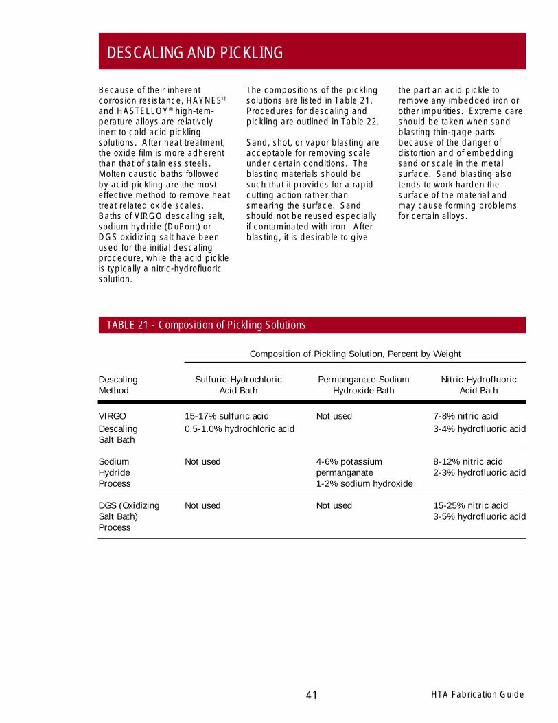
HTA Fabrication Guide41
DESCALING AND PICKLING
Because of their inherentcorrosion resistance, HAYNES®
and HASTELLOY® high-tem-perature alloys are relativelyinert to cold acid picklingsolutions. After heat treatment,the oxide film is more adherentthan that of stainless steels.Molten caustic baths followedby acid pickling are the mosteffective method to remove heattreat related oxide scales.Baths of VIRGO descaling salt,sodium hydride (DuPont) orDGS oxidizing salt have beenused for the initial descalingprocedure, while the acid pickleis typically a nitric-hydrofluoricsolution.
The compositions of the picklingsolutions are listed in Table 21.Procedures for descaling andpickling are outlined in Table 22.
Sand, shot, or vapor blasting areacceptable for removing scaleunder certain conditions. Theblasting materials should besuch that it provides for a rapidcutting action rather thansmearing the surface. Sandshould not be reused especiallyif contaminated with iron. Afterblasting, it is desirable to give
the part an acid pickle toremove any imbedded iron orother impurities. Extreme careshould be taken when sandblasting thin-gage partsbecause of the danger ofdistortion and of embeddingsand or scale in the metalsurface. Sand blasting alsotends to work harden thesurface of the material andmay cause forming problemsfor certain alloys.
Descaling Sulfuric-Hydrochloric Permanganate-Sodium Nitric-HydrofluoricMethod Acid Bath Hydroxide Bath Acid Bath
VIRGO 15-17% sulfuric acid Not used 7-8% nitric acidDescaling 0.5-1.0% hydrochloric acid 3-4% hydrofluoric acidSalt Bath
Sodium Not used 4-6% potassium 8-12% nitric acidHydride permanganate 2-3% hydrofluoric acidProcess 1-2% sodium hydroxide
DGS (Oxidizing Not used Not used 15-25% nitric acidSalt Bath) 3-5% hydrofluoric acidProcess
TABLE 21 - Composition of Pickling Solutions
Composition of Pickling Solution, Percent by Weight
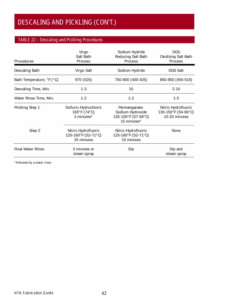
Virgo Sodium Hydride DGSSalt Bath Reducing Salt Bath Oxidizing Salt Bath
Procedures Process Process Process
Descaling Bath Virgo Salt Sodium Hydride DGS Salt
Bath Temperature, °F (°C) 970 (520) 750-800 (400-425) 850-950 (455-510)
Descaling Time, Min. 1-3 15 2-10
Water Rinse Time, Min. 1-2 1-2 1-5
Pickling Step 1 Sulfuric-Hydrochloric Permanganate- Nitric-Hydrofluoric165°F (74°C) Sodium Hydroxide 130-150°F (54-66°C)3 minutes* 135-155°F (57-68°C) 10-20 minutes
15 minutes*
Step 2 Nitric-Hydrofluoric Nitric-Hydrofluoric None125-160°F (52-71°C) 125-160°F (52-71°C)
25 minutes 15 minutes
Final Water Rinse 3 minutes or Dip Dip andsteam spray steam spray
*Followed by a water rinse
42HTA Fabrication Guide
DESCALING AND PICKLING (CON'T.)
TABLE 22 - Descaling and Pickling Procedures
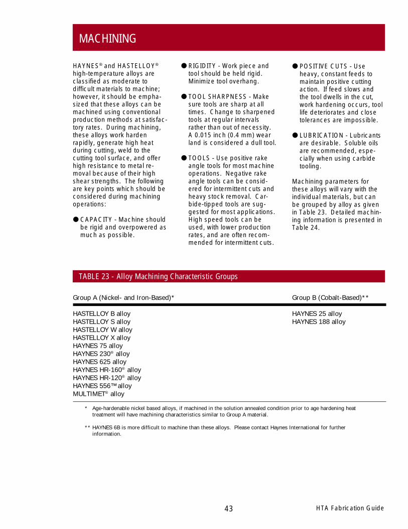
HTA Fabrication Guide43
MACHINING
HAYNES® and HASTELLOY®
high-temperature alloys areclassified as moderate todifficult materials to machine;however, it should be empha-sized that these alloys can bemachined using conventionalproduction methods at satisfac-tory rates. During machining,these alloys work hardenrapidly, generate high heatduring cutting, weld to thecutting tool surface, and offerhigh resistance to metal re-moval because of their highshear strengths. The followingare key points which should beconsidered during machiningoperations:
● CAPACITY - Machine shouldbe rigid and overpowered asmuch as possible.
● RIGIDITY - Work piece andtool should be held rigid.Minimize tool overhang.
● TOOL SHARPNESS - Makesure tools are sharp at alltimes. Change to sharpenedtools at regular intervalsrather than out of necessity.A 0.015 inch (0.4 mm) wearland is considered a dull tool.
● TOOLS - Use positive rakeangle tools for most machineoperations. Negative rakeangle tools can be consid-ered for intermittent cuts andheavy stock removal. Car-bide-tipped tools are sug-gested for most applications.High speed tools can beused, with lower productionrates, and are often recom-mended for intermittent cuts.
● POSITIVE CUTS - Useheavy, constant feeds tomaintain positive cuttingaction. If feed slows andthe tool dwells in the cut,work hardening occurs, toollife deteriorates and closetolerances are impossible.
● LUBRICATION - Lubricantsare desirable. Soluble oilsare recommended, espe-cially when using carbidetooling.
Machining parameters forthese alloys will vary with theindividual materials, but canbe grouped by alloy as givenin Table 23. Detailed machin-ing information is presented inTable 24.
TABLE 23 - Alloy Machining Characteristic Groups
Group A (Nickel- and Iron-Based)* Group B (Cobalt-Based)**
HASTELLOY B alloy HAYNES 25 alloyHASTELLOY S alloy HAYNES 188 alloyHASTELLOY W alloyHASTELLOY X alloyHAYNES 75 alloyHAYNES 230® alloyHAYNES 625 alloyHAYNES HR-160® alloyHAYNES HR-120® alloyHAYNES 556™ alloyMULTIMET® alloy
* Age-hardenable nickel based alloys, if machined in the solution annealed condition prior to age hardening heattreatment will have machining characteristics similar to Group A material.
** HAYNES 6B is more difficult to machine than these alloys. Please contact Haynes International for furtherinformation.

RecommendedOperations Tool Types Tool Geometry and Set-up**
Roughing, with Carbide: C-2 or C-3 Negative rake square insert, 45° SCEA1, 1/32 in.severe interruptions; grade nose radius. Tool holder: 5° negative backTurning or Facing rake, 5° negative side rake
Normal roughing; Same as above Same as aboveTurning or Facing
Finishing; Same as above Positive rake square insert, if possible,Turning or Facing 45° SCEA, 1/32 in. nose radius. Tool holder:
5° positive back and side rake.
Rough Boring Same as above If insert-type boring bar, use standardpositive rake tools with largest possibleSCEA and 1/16 in. nose radius. If brazedtool bar, grind 0° back rake, 10° positiveside rake, 1/32 in. nose radius and largestpossible SCEA
Finish Boring Same as above Use standard positive rake tools on insert-type bars. Grind brazed bars as forfinish turning, except back rake may bebest at 0°.
Face Milling High speed steel: M-2, Radial and axial rake 0° to 10° positive,M-7 or M-40 series6 45° corner angle, 10° relief angle.
Carbide: C-2 grade Use positive axial and radial rake, 45°(Marginal performance) corner angle, 10° relief angle.
End Milling High speed steel: M-40 If possible, use short mills with four orseries or T-15 more flutes for rigidity.
Carbide: C-2 grade Not recommended but may be successfulon good set-ups.
44HTA Fabrication Guide
MACHINING (CON'T.)
TABLE 24 - Recommended Tools and Machining Parameters

Surface Feet Per Minute* Inch** Inch** Lubricant
30-50 for group A 0.004-0.008 per 0.150 Dry2, oil3, orand group B alloys revolution water-base4,7
90 for group A and 0.010 per 0.150 Dry, oil, or80 for group B alloys5 revolution water-base
95-110 for group A and 0.005-0.007 per 0.040 Dry or90 for group B alloys revolution water-base
70 for group A and 0.005-0.008 per 0.125 Dry, oil, or60 for group B alloys5 revolution water-base
95-110 for group A and 0.002-0.004 per 0.040 Water-base90 for group B alloys revolution
20-30 for group A and 0.003-0.005 per tooth Oil or water-20-25 for group B alloys for group A and base
group B alloys
50-60 for group A and 0.005-0.008 per tooth Oil or water-35-40 for group B alloys for group A and 0.005 base
per tooth for group B alloys
20-25 for group A and Feed per tooth: Oil or water-15-20 for group B alloys Diameter Group A Group B base
1/4 in. 0.002 0.0011/2 in. 0.002 0.00153/4 in. 0.003 0.002
1 in. 0.004 0.003
50-60 for group A and Same as above Oil or water-40-50 for group B alloys base
* To convert to surface meters per minute, multiply by 0.30.** To convert from inches to millimeters, multiply by 25.4.
HTA Fabrication Guide45
MACHINING (CON'T.)
Speed Feed Depth of Cut
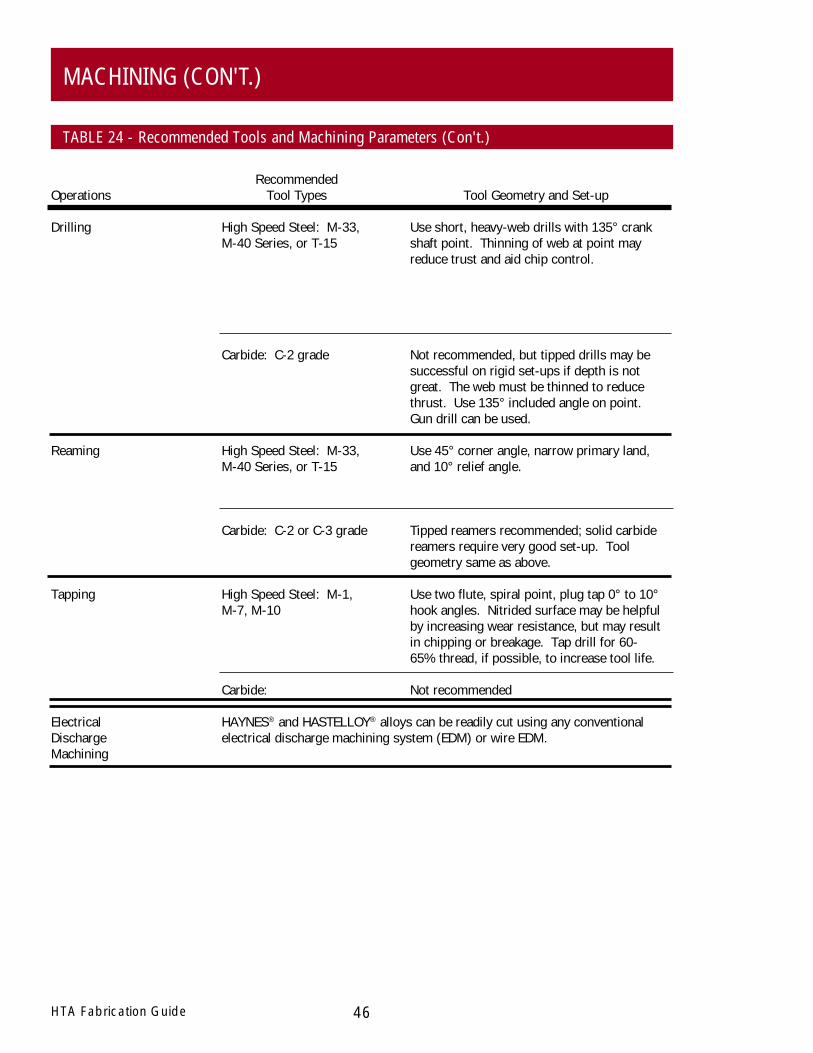
RecommendedOperations Tool Types Tool Geometry and Set-up
Drilling High Speed Steel: M-33, Use short, heavy-web drills with 135° crankM-40 Series, or T-15 shaft point. Thinning of web at point may
reduce trust and aid chip control.
Carbide: C-2 grade Not recommended, but tipped drills may besuccessful on rigid set-ups if depth is notgreat. The web must be thinned to reducethrust. Use 135° included angle on point.Gun drill can be used.
Reaming High Speed Steel: M-33, Use 45° corner angle, narrow primary land,M-40 Series, or T-15 and 10° relief angle.
Carbide: C-2 or C-3 grade Tipped reamers recommended; solid carbidereamers require very good set-up. Toolgeometry same as above.
Tapping High Speed Steel: M-1, Use two flute, spiral point, plug tap 0° to 10°M-7, M-10 hook angles. Nitrided surface may be helpful
by increasing wear resistance, but may resultin chipping or breakage. Tap drill for 60-65% thread, if possible, to increase tool life.
Carbide: Not recommended
Electrical HAYNES® and HASTELLOY® alloys can be readily cut using any conventionalDischarge electrical discharge machining system (EDM) or wire EDM.Machining
46HTA Fabrication Guide
MACHINING (CON'T.)
TABLE 24 - Recommended Tools and Machining Parameters (Con't.)
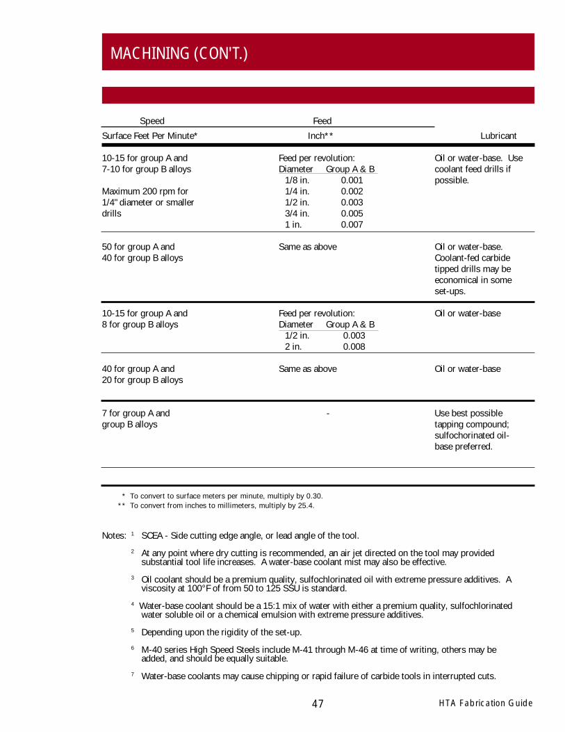
Surface Feet Per Minute* Inch** Lubricant
10-15 for group A and Feed per revolution: Oil or water-base. Use7-10 for group B alloys Diameter Group A & B coolant feed drills if
1/8 in. 0.001 possible.Maximum 200 rpm for 1/4 in. 0.0021/4" diameter or smaller 1/2 in. 0.003drills 3/4 in. 0.005
1 in. 0.007
50 for group A and Same as above Oil or water-base.40 for group B alloys Coolant-fed carbide
tipped drills may beeconomical in someset-ups.
10-15 for group A and Feed per revolution: Oil or water-base8 for group B alloys Diameter Group A & B
1/2 in. 0.0032 in. 0.008
40 for group A and Same as above Oil or water-base20 for group B alloys
7 for group A and - Use best possiblegroup B alloys tapping compound;
sulfochorinated oil-base preferred.
Notes: 1 SCEA - Side cutting edge angle, or lead angle of the tool.
2 At any point where dry cutting is recommended, an air jet directed on the tool may providedsubstantial tool life increases. A water-base coolant mist may also be effective.
3 Oil coolant should be a premium quality, sulfochlorinated oil with extreme pressure additives. Aviscosity at 100°F of from 50 to 125 SSU is standard.
4 Water-base coolant should be a 15:1 mix of water with either a premium quality, sulfochlorinatedwater soluble oil or a chemical emulsion with extreme pressure additives.
5 Depending upon the rigidity of the set-up.
6 M-40 series High Speed Steels include M-41 through M-46 at time of writing, others may beadded, and should be equally suitable.
7 Water-base coolants may cause chipping or rapid failure of carbide tools in interrupted cuts.
HTA Fabrication Guide47
MACHINING (CON'T.)
Speed Feed
* To convert to surface meters per minute, multiply by 0.30.** To convert from inches to millimeters, multiply by 25.4.
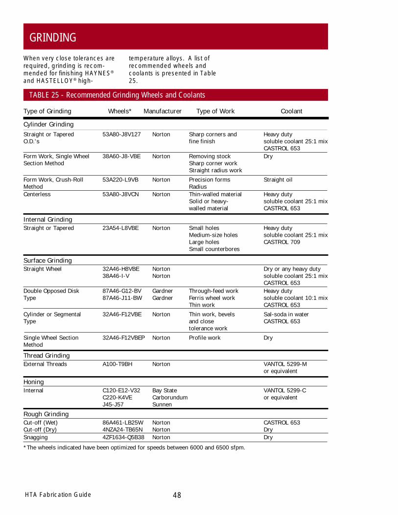
Straight or Tapered 53A80-J8V127 Norton Sharp corners and Heavy dutyO.D.'s fine finish soluble coolant 25:1 mix
CASTROL 653
Type of Grinding Wheels* Manufacturer Type of Work Coolant
48HTA Fabrication Guide
GRINDING
When very close tolerances arerequired, grinding is recom-mended for finishing HAYNES®
and HASTELLOY® high-
temperature alloys. A list ofrecommended wheels andcoolants is presented in Table25.
TABLE 25 - Recommended Grinding Wheels and Coolants
Cylinder Grinding
Form Work, Single Wheel 38A60-J8-VBE Norton Removing stock DrySection Method Sharp corner work
Straight radius work
Form Work, Crush-Roll 53A220-L9VB Norton Precision forms Straight oilMethod RadiusCenterless 53A80-J8VCN Norton Thin-walled material Heavy duty
Solid or heavy- soluble coolant 25:1 mixwalled material CASTROL 653
Internal GrindingStraight or Tapered 23A54-L8VBE Norton Small holes Heavy duty
Medium-size holes soluble coolant 25:1 mixLarge holes CASTROL 709Small counterbores
Surface GrindingStraight Wheel 32A46-H8VBE Norton Dry or any heavy duty
38A46-I-V Norton soluble coolant 25:1 mixCASTROL 653
Double Opposed Disk 87A46-G12-BV Gardner Through-feed work Heavy dutyType 87A46-J11-BW Gardner Ferris wheel work soluble coolant 10:1 mix
Thin work CASTROL 653
Cylinder or Segmental 32A46-F12VBE Norton Thin work, bevels Sal-soda in waterType and close CASTROL 653
tolerance work
Single Wheel Section 32A46-F12VBEP Norton Profile work DryMethod
Thread GrindingExternal Threads A100-T9BH Norton VANTOL 5299-M
or equivalent
HoningInternal C120-E12-V32 Bay State VANTOL 5299-C
C220-K4VE Carborundum or equivalentJ45-J57 Sunnen
Rough GrindingCut-off (Wet) 86A461-LB25W Norton CASTROL 653Cut-off (Dry) 4NZA24-TB65N Norton DrySnagging 4ZF1634-Q5B38 Norton Dry
*The wheels indicated have been optimized for speeds between 6000 and 6500 sfpm.
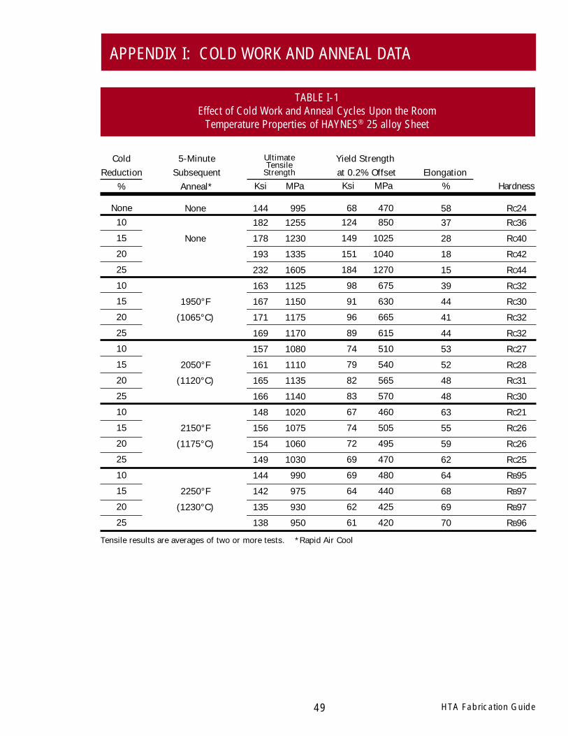
HTA Fabrication Guide49
APPENDIX I: COLD WORK AND ANNEAL DATA
TABLE I-1Effect of Cold Work and Anneal Cycles Upon the Room
Temperature Properties of HAYNES® 25 alloy Sheet
Hardness
RC24RC36
RC40
RC42
RC44
RC32
RC30
RC32
RC32
RC27
RC28
RC31
RC30
RC21
RC26
RC26
RC25
RB95
RB97
RB97
RB96
MPa
9951255
1230
1335
1605
1125
1150
1175
1170
1080
1110
1135
1140
1020
1075
1060
1030
990
975
930
950
Ksi
144182
178
193
232
163
167
171
169
157
161
165
166
148
156
154
149
144
142
135
138
%
5837
28
18
15
39
44
41
44
53
52
48
48
63
55
59
62
64
68
69
70
5-MinuteSubsequent
Anneal*
None10
15
20
25
10
15
20
25
10
15
20
25
10
15
20
25
10
15
20
25
ColdReduction
%Elongation
UltimateTensile
Strength
None
None
1950°F
(1065°C)
2050°F
(1120°C)
2150°F
(1175°C)
2250°F
(1230°C)
Tensile results are averages of two or more tests. *Rapid Air Cool
MPa
470850
1025
1040
1270
675
630
665
615
510
540
565
570
460
505
495
470
480
440
425
420
Ksi
68124
149
151
184
98
91
96
89
74
79
82
83
67
74
72
69
69
64
62
61
Yield Strength at 0.2% Offset
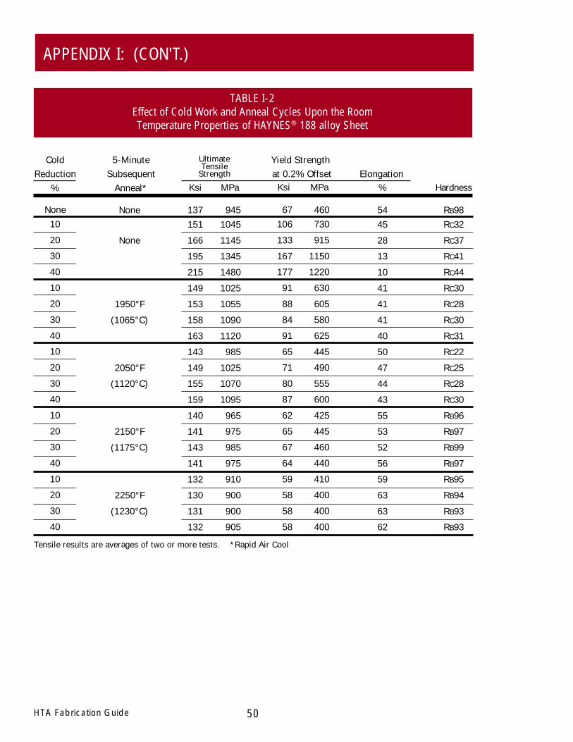
50HTA Fabrication Guide
APPENDIX I: (CON'T.)
TABLE I-2Effect of Cold Work and Anneal Cycles Upon the RoomTemperature Properties of HAYNES® 188 alloy Sheet
Hardness
RB98RC32
RC37
RC41
RC44
RC30
RC28
RC30
RC31
RC22
RC25
RC28
RC30
RB96
RB97
RB99
RB97
RB95
RB94
RB93
RB93
MPa
9451045
1145
1345
1480
1025
1055
1090
1120
985
1025
1070
1095
965
975
985
975
910
900
900
905
Ksi
137151
166
195
215
149
153
158
163
143
149
155
159
140
141
143
141
132
130
131
132
%
5445
28
13
10
41
41
41
40
50
47
44
43
55
53
52
56
59
63
63
62
5-MinuteSubsequent
Anneal*
None10
20
30
40
10
20
30
40
10
20
30
40
10
20
30
40
10
20
30
40
ColdReduction
%Elongation
UltimateTensile
Strength
None
None
1950°F
(1065°C)
2050°F
(1120°C)
2150°F
(1175°C)
2250°F
(1230°C)
Tensile results are averages of two or more tests. *Rapid Air Cool
MPa
460730
915
1150
1220
630
605
580
625
445
490
555
600
425
445
460
440
410
400
400
400
Ksi
67106
133
167
177
91
88
84
91
65
71
80
87
62
65
67
64
59
58
58
58
Yield Strength at 0.2% Offset

None10
20
30
40
50
10
20
30
40
50
10
20
30
40
50
10
20
30
40
50
10
20
30
40
50
HTA Fabrication Guide51
APPENDIX I: (CON'T.)
TABLE I-3Effect of Cold Work and Anneal Cycles Upon the RoomTemperature Properties of HAYNES® 230® alloy Sheet
Hardness
RB95RC28
RC35
RC39
RC40
RC42
RC24
RC26
RB99
RC23
RC24
RB98
RB97
RB99
RB99
RC23
RB92
RB96
RB98
RB98
RB98
RB92
RB92
RB92
RB91
RB89
MPa
885995
1130
1295
1390
1480
990
980
980
1005
1020
960
935
965
980
990
895
925
950
960
950
860
885
870
870
880
Ksi
128145
164
188
202
215
144
142
142
146
148
139
136
140
142
144
130
134
138
139
138
125
128
126
126
128
%
4732
17
10
8
6
33
36
36
32
35
37
39
38
36
36
44
40
39
38
39
47
45
48
47
46
5-MinuteSubsequent
Anneal*
ColdReduction
%Elongation
UltimateTensile
Strength
MPa
425715
920
1105
1190
1275
635
555
525
560
595
555
450
495
525
555
385
445
485
505
495
360
390
370
370
375
Ksi
62104
133
160
172
185
92
81
76
81
86
81
65
72
76
81
56
64
70
73
72
52
57
54
53
55
Tensile results are averages of two or more tests. *Rapid Air Cool
None
None
1950°F
(1065°C)
2050°F
(1120°C)
2150°F
(1175°C)
2250°F
(1230°C)
Yield Strength at 0.2% Offset

52HTA Fabrication Guide
APPENDIX I: (CON'T.)
TABLE I-4Effect of Cold Work and Anneal Cycles Upon the Room
Temperature Properties of HAYNES® 556™ alloy Sheet
None10
20
30
40
50
10
20
30
40
50
10
20
30
40
50
10
20
30
40
50
10
20
30
40
50
Hardness
RB88RC25
RC32
RC39
RC41
RC42
RB99
RC25
RC25
RC25
RC25
RB98
RC23
RB97
RC23
RC23
RB93
RB92
RB96
RB97
RB98
RB89
RB89
RB89
RB88
RB89
MPa
795880
980
1190
1305
1410
840
875
930
920
930
845
860
865
885
905
810
830
850
860
875
Ksi
115128
142
173
189
204
122
127
135
133
135
122
125
125
128
131
117
120
124
125
127
%
5135
24
12
10
8
34
30
27
31
32
37
35
38
37
33
48
45
43
42
35
5-MinuteSubsequent
Anneal*
ColdReduction
%Elongation
UltimateTensile
Strength
MPa
365645
780
995
1075
1170
530
610
640
550
570
530
530
455
490
535
380
405
440
460
485
Ksi
5393
113
144
156
170
77
89
93
80
83
77
77
66
71
78
55
58
64
67
71
Tensile results are averages of two or more tests. *Rapid Air Cool
None
None
1850°F
(1010°C)
1950°F
(1065°C)
2050°F
(1120°C)
2150°F
(1175°C) Not Available
Yield Strength at 0.2% Offset

None10
20
30
40
50
10
20
30
40
50
10
20
30
40
50
10
20
30
40
50
10
20
30
40
50
HTA Fabrication Guide53
APPENDIX I: (CON'T.)
TABLE I-5Effect of Cold Work and Anneal Cycles Upon the RoomTemperature Properties of HAYNES® 625 alloy Sheet
Hardness
RB97RC32
RC37
RC40
RC42
RC45
MPa
9151040
1165
1315
1440
1540
925
950
970
970
975
915
950
965
975
975
880
930
875
945
900
840
850
840
840
825
Ksi
133151
169
191
209
223
134
138
141
141
141
133
137
140
142
141
128
135
127
137
130
122
124
122
122
119
%
4630
16
11
8
5
46
44
44
42
42
46
45
44
42
42
50
46
52
44
50
55
55
56
55
58
5-MinuteSubsequent
Anneal*
ColdReduction
%Elongation
UltimateTensile
Strength
MPa
480780
965
1115
1230
1270
435
490
535
565
560
425
485
530
575
570
405
460
400
500
420
360
370
365
360
350
Ksi
70113
140
162
178
184
63
71
78
82
82
61
71
77
83
82
58
67
58
72
61
52
54
53
52
51
Tensile results are averages of two or more tests. *Rapid Air Cool
None
None
1850°F
(1010°C)
1950°F
(1065°C)
2050°F
(1120°C)
2150°F
(1175°C)
Yield Strength at 0.2% Offset
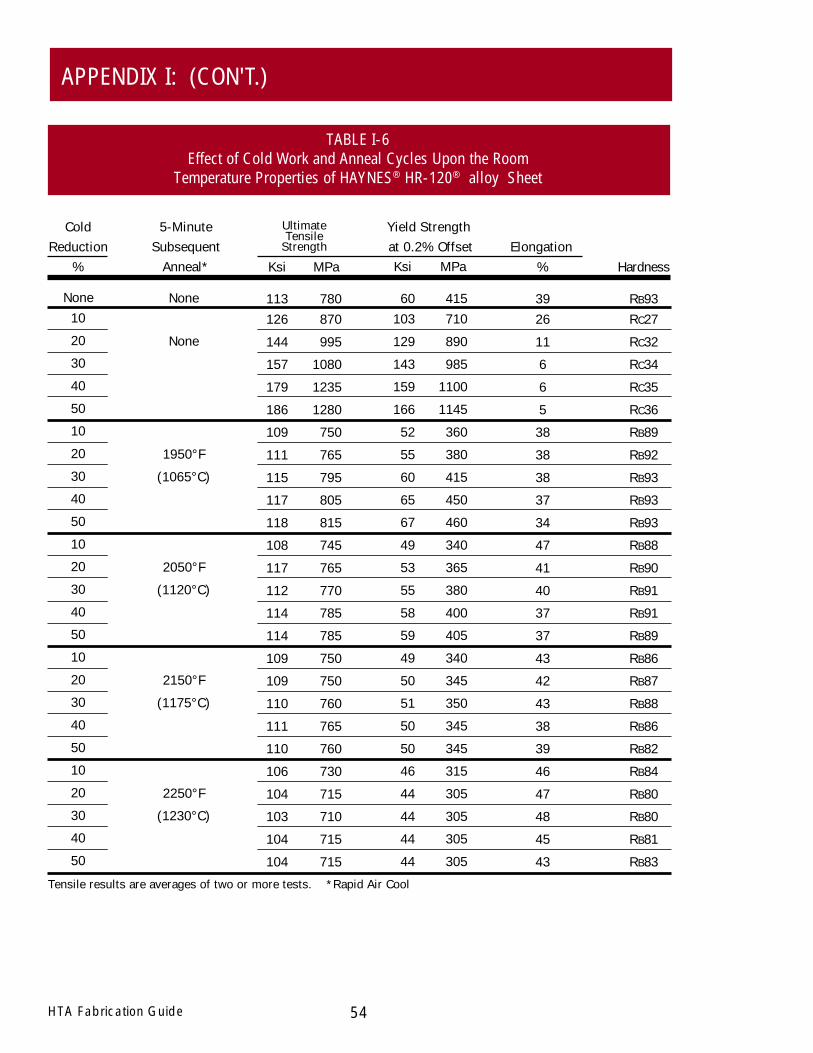
Hardness
RB93RC27
RC32
RC34
RC35
RC36
RB89
RB92
RB93
RB93
RB93
RB88
RB90
RB91
RB91
RB89
RB86
RB87
RB88
RB86
RB82
RB84
RB80
RB80
RB81
RB83
54HTA Fabrication Guide
APPENDIX I: (CON'T.)
TABLE I-6Effect of Cold Work and Anneal Cycles Upon the Room
Temperature Properties of HAYNES® HR-120® alloy Sheet
None10
20
30
40
50
10
20
30
40
50
10
20
30
40
50
10
20
30
40
50
10
20
30
40
50
5-MinuteSubsequent
Anneal*
ColdReduction
%Elongation
UltimateTensile
Strength
Tensile results are averages of two or more tests. *Rapid Air Cool
None
None
1950°F
(1065°C)
2050°F
(1120°C)
2150°F
(1175°C)
2250°F
(1230°C)
Yield Strength at 0.2% Offset
MPa
780870
995
1080
1235
1280
750
765
795
805
815
745
765
770
785
785
750
750
760
765
760
730
715
710
715
715
Ksi
113126
144
157
179
186
109
111
115
117
118
108
117
112
114
114
109
109
110
111
110
106
104
103
104
104
%
3926
11
6
6
5
38
38
38
37
34
47
41
40
37
37
43
42
43
38
39
46
47
48
45
43
MPa
415710
890
985
1100
1145
360
380
415
450
460
340
365
380
400
405
340
345
350
345
345
315
305
305
305
305
Ksi
60103
129
143
159
166
52
55
60
65
67
49
53
55
58
59
49
50
51
50
50
46
44
44
44
44

None10
20
30
40
50
10
20
30
40
50
10
20
30
40
50
10
20
30
40
50
10
20
30
40
50
HTA Fabrication Guide55
APPENDIX I: (CON'T.)
TABLE I-7Effect of Cold Work and Anneal Cycles Upon the Room
Temperature Properties of HAYNES® HR-160® alloy Sheet
5-MinuteSubsequent
Anneal*
ColdReduction
%Elongation
UltimateTensile
Strength
Tensile results are averages of two or more tests. *Rapid Air Cool
None
None
1850°F
(1010°C)
1950°F
(1065°C)
2050°F
(1120°C)
2150°F
(1175°C)
Hardness
RB88RC21
RC30
RC35
RC39
RC41
MPa
750820
930
1135
1285
1385
775
805
850
870
890
735
735
730
705
735
Ksi
109119
135
164
187
201
112
117
123
126
129
106
106
106
102
107
%
6852
28
13
9
8
61
57
51
50
47
72
68
69
69
65
MPa
345555
775
1000
1130
1200
325
335
385
415
445
285
285
285
270
280
Ksi
5081
112
145
164
174
47
49
56
61
64
41
41
41
39
41
Yield Strength at 0.2% Offset
Not Available
Not Available
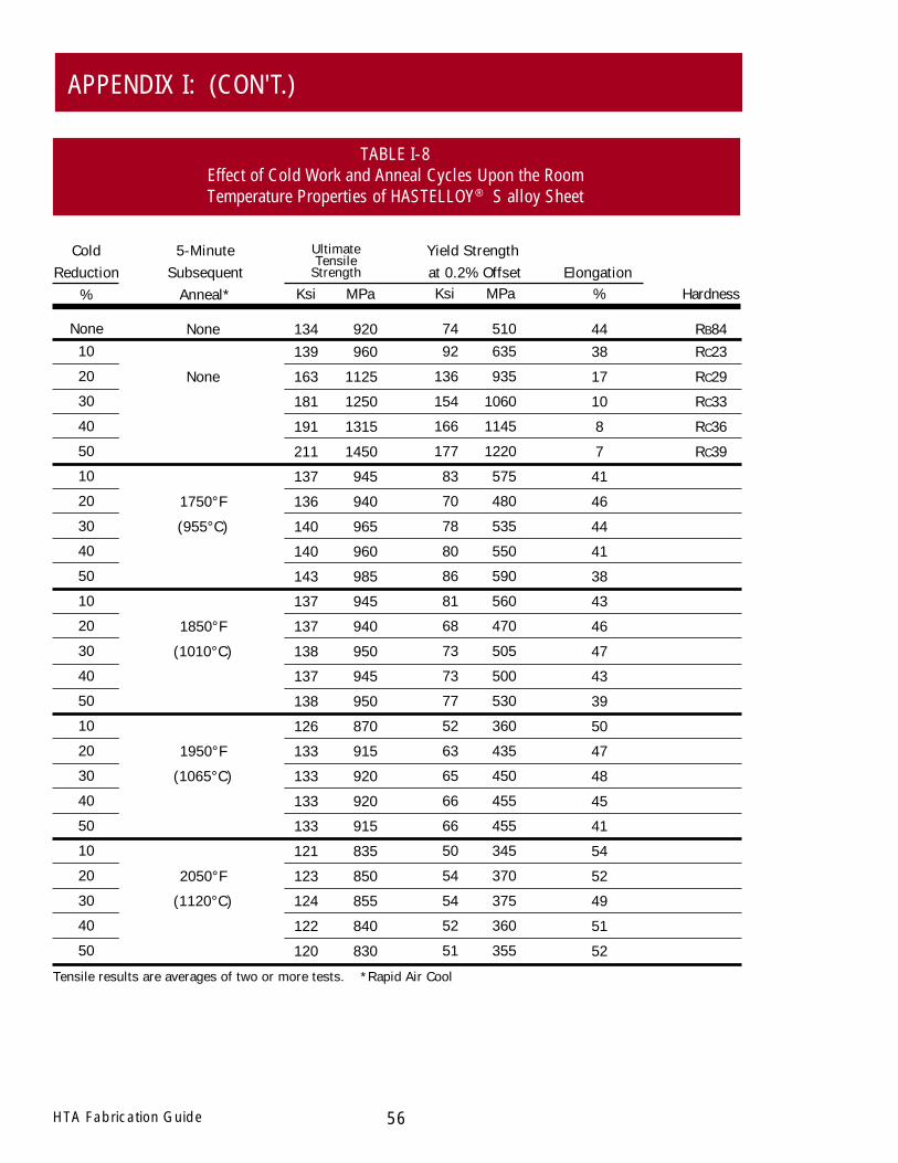
56HTA Fabrication Guide
APPENDIX I: (CON'T.)
TABLE I-8Effect of Cold Work and Anneal Cycles Upon the RoomTemperature Properties of HASTELLOY® S alloy Sheet
None10
20
30
40
50
10
20
30
40
50
10
20
30
40
50
10
20
30
40
50
10
20
30
40
50
Hardness
RB84RC23
RC29
RC33
RC36
RC39
MPa
920960
1125
1250
1315
1450
945
940
965
960
985
945
940
950
945
950
870
915
920
920
915
835
850
855
840
830
Ksi
134139
163
181
191
211
137
136
140
140
143
137
137
138
137
138
126
133
133
133
133
121
123
124
122
120
%
4438
17
10
8
7
41
46
44
41
38
43
46
47
43
39
50
47
48
45
41
54
52
49
51
52
5-MinuteSubsequent
Anneal*
ColdReduction
%Elongation
UltimateTensile
Strength
MPa
510635
935
1060
1145
1220
575
480
535
550
590
560
470
505
500
530
360
435
450
455
455
345
370
375
360
355
Ksi
7492
136
154
166
177
83
70
78
80
86
81
68
73
73
77
52
63
65
66
66
50
54
54
52
51
Tensile results are averages of two or more tests. *Rapid Air Cool
None
None
1750°F
(955°C)
1850°F
(1010°C)
1950°F
(1065°C)
2050°F
(1120°C)
Yield Strength at 0.2% Offset
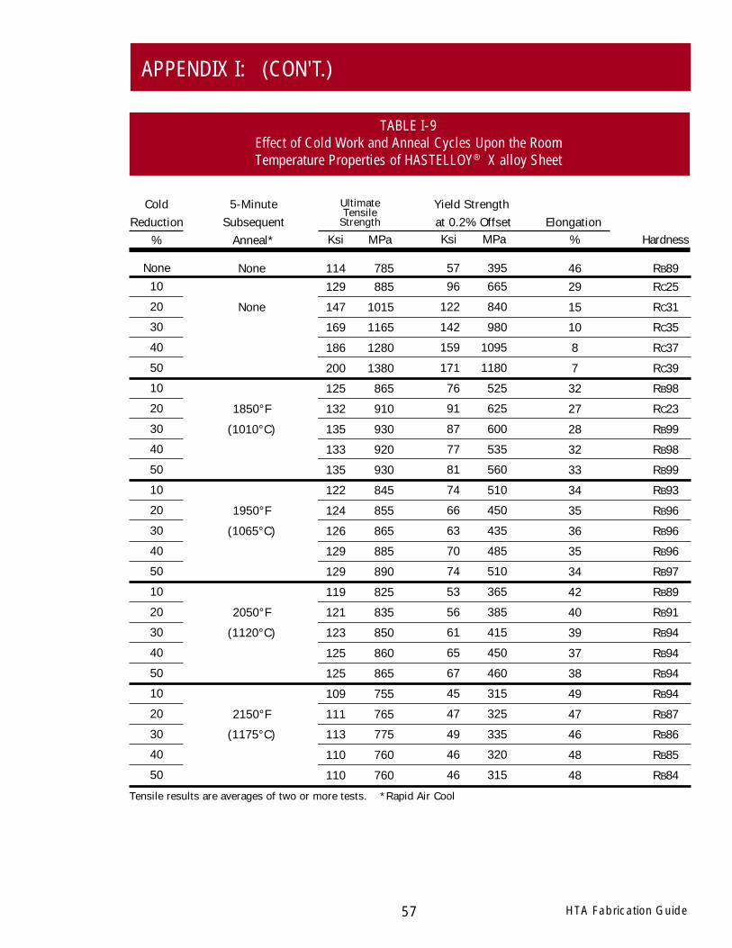
None10
20
30
40
50
10
20
30
40
50
10
20
30
40
50
10
20
30
40
50
10
20
30
40
50
HTA Fabrication Guide57
APPENDIX I: (CON'T.)
TABLE I-9Effect of Cold Work and Anneal Cycles Upon the RoomTemperature Properties of HASTELLOY® X alloy Sheet
Hardness
RB89RC25
RC31
RC35
RC37
RC39
RB98
RC23
RB99
RB98
RB99
RB93
RB96
RB96
RB96
RB97
RB89
RB91
RB94
RB94
RB94
RB94
RB87
RB86
RB85
RB84
MPa
785885
1015
1165
1280
1380
865
910
930
920
930
845
855
865
885
890
825
835
850
860
865
755
765
775
760
760
Ksi
114129
147
169
186
200
125
132
135
133
135
122
124
126
129
129
119
121
123
125
125
109
111
113
110
110
%
4629
15
10
8
7
32
27
28
32
33
34
35
36
35
34
42
40
39
37
38
49
47
46
48
48
5-MinuteSubsequent
Anneal*
ColdReduction
%Elongation
UltimateTensile
Strength
MPa
395665
840
980
1095
1180
525
625
600
535
560
510
450
435
485
510
365
385
415
450
460
315
325
335
320
315
Ksi
5796
122
142
159
171
76
91
87
77
81
74
66
63
70
74
53
56
61
65
67
45
47
49
46
46
Tensile results are averages of two or more tests. *Rapid Air Cool
None
None
1850°F
(1010°C)
1950°F
(1065°C)
2050°F
(1120°C)
2150°F
(1175°C)
Yield Strength at 0.2% Offset
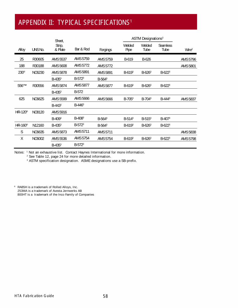
58HTA Fabrication Guide
APPENDIX II: TYPICAL SPECIFICATIONS1
Notes: 1 Not an exhaustive list. Contact Haynes International for more information.2 See Table 12, page 24 for more detailed information.3 ASTM specification designation. ASME designations use a SB-prefix.
Sheet,Strip,
& Plate
AMS 5537
AMS 5608
AMS 5878
B-4353
AMS 5874
B-4353
AMS 5599
B-4433
AMS 5916
B-4093
B-4353
AMS 5873
AMS 5536
B-4353
WeldedPipe
B-619
B-6193
B-6193
B-7053
B-5143
B-6193
B-6193
SeamlessTube
B-6223
B-6223
B-4443
B-4073
B-6223
B-6223
WeldedTube
B-626
B-6263
B-6263
B-7043
B-5153
B-6263
B-6263
ASTM Designations3
UNS No.
R30605
R30188
NO6230
R30556
NO6625
NO8120
N12160
NO6635
NO6002
Alloy
25
188
230®
556™
625
HR-120®
HR-160®
S
X
Bar & Rod
AMS 5759
AMS 5772
AMS 5891
B-5723
AMS 5877
B-572
AMS 5666
B-4463
B-4083
B-5723
AMS 5711
AMS 5754
B-5723
Forgings
AMS 5759
AMS 5772
AMS 5891
B-5643
AMS 5877
AMS 5666
B-5643
B-5643
AMS 5711
AMS 5754
Wire2
AMS 5796
AMS 5801
AMS 5837
AMS 5838
AMS 5798
® RA85H is a trademark of Rolled Alloys, Inc.253MA is a trademark of Avesta Jernwerks AB800HT is a trademark of the Inco Family of Companies

www.haynesintl.com
For Referral to Authorized Distributors in your areaFax: 1-765-456-6079
Printed in U.S.A.
B-2, B-3®, C-4, C-22®, C-276, C-2000®, D-205™, G-3, G-30®, G-50®, and N
Corrosion-Wear Resistant Alloy
ULTIMET®
25, R-41, 75, HR-120®, HR-160®, 188, 214™, 230®, 230-W™, 242™, 263, 556™, 617, 625, 65SQ®, 718,X-750, MULTIMET®, and Waspaloy
Wear-Resistant Alloy
Ti-3Al-2.5V
HASTELLOY Family of Heat-Resistant Alloys
HASTELLOY ® Family of Corrosion-Resistant Alloys
S, W, and X
HAYNES ® Family of Heat-Resistant Alloys
6B
HAYNES Titanium Alloy Tubular
For More Information Contact:
Properties Data:
Bar, Billet, Plate, Sheet, Strip, Coils, Seamless or Welded Pipe & Tubing, Pipe Fittings, Flanges,Fittings, Welding Wire, and Coated Electrodes
Standard Forms:
STANDARD PRODUCTS By Brand or Alloy Designation:
North American Service Centers International Service Centers
(All trademarks are owned by Haynes International, Inc.)
The data and information in this publication are basedon work conducted principally by Haynes International, Inc.and occasionally supplemented by information from the openliterature, and are believed to be reliable. However, Haynesdoes not make any warranty or assume any legal liability orresponsibility for its accuracy, completeness, or usefulness,nor does Haynes represent that its use would not infringe
upon private rights. Any suggestions as to uses and applica-tions for specific alloys are opinions only and Haynes Interna-tional, Inc. makes no warranty of results to be obtained in anyparticular situation. For specific concentrations of elementspresent in a particular product and a discussion of thepotential health affects thereof, refer to the Material SafetyData Sheet supplied by Haynes International, Inc.
Midwest Service Center1020 W. Park AvenueP.O. Box 9013Kokomo, Indiana 46904-9013Tel: 765-456-6012
800-354-0806Fax: 765-456-6905
Southern Service CenterThe Northwood Industrial Park12241 FM 529Houston, Texas 77041Tel: 713-937-7597
800-231-4548Fax: 713-937-4596
Tubular Products3786 Second StreetArcadia, Louisiana 71001-9701Tel: 318-263-9571
800-648-8823Fax: 318-263-8088
ItalyHaynes International, S.R.L.Viale Brianza, 820127 MilanoItalyTel: 39-2-2614-1331Fax: 39-2-282-8273
SwitzerlandNickel Contor AGHohlstrasse 534CH-8048 ZurichSwitzerlandTel: 41-1-434-7080Fax: 41-1-431-8787
SingaporeHaynes Pacific PTE LTD15 McCallum Street#05-03 Natwest CentreSingapore 069045Tel: 65-6-222-3213Fax: 65-6-222-3280
EnglandHaynes International, Ltd.P.O. Box 10Parkhouse StreetOpenshawManchester, M11 2ERTel: 44-161-230-7777Fax: 44-161-223-2412
FranceHaynes International, S.A.R.L.Boite Postale 30395617 Cergy PontoiseCedex, FranceTel: 33-1-34-48-3100Fax: 33-1-30-37-8022
Eastern Service Center430 Hayden Station RoadWindsor, Connecticut 06095Tel: 860-688-7771
800-426-1963Fax: 860-688-5550
Western Service CenterStadium Plaza1520 South Sinclair StreetAnaheim, California 92806Tel: 714-978-1775
800-531-0285Fax: 714-978-1743
061902