Embed Size (px)
Citation preview
Communication Electrochemistry, 88(4), 256–258 (2020)
Fabrication of Fe-Metal Organic Framework-derived Fe2O3 Nanoparticle Li-ion Battery
Yu-Sung KIM, Hyun-Ik CHO, Ye-Eun PARK, and Byoung-Nam PARK*
Department of Materials Science and Engineering, Hongik University, 72-1, Sangsu-dong, Mapo-gu, Seoul 121-791, Korea
* Corresponding author: [email protected]
ABSTRACTWe, for the first time, fabricated an additive-free battery electrode composed of Fe-zeolitic imidazolate frameworks-derived Fe2O3
nanoparticles (NPs) incorporated in carbon shells (Fe2O3@C) through electrophoretic deposition (EPD). High specific capacity of Fe2O3@Cwithout additives comparable to that of the theoretical capacity (1007mAh/g) suggests that the electrochemical conversion reactionsaccompanied by lithiation and delithiation process are not significantly limited by the absence of the conductive agents and binders. Theadditive-free system paves the way for an efficient experimental probe to investigate the intrinsic electrochemical properties of the metal-organic framework-derived nanostructures.
© The Author(s) 2020. Published by ECSJ. This is an open access article distributed under the terms of the Creative Commons Attribution 4.0 License (CC BY,http://creativecommons.org/licenses/by/4.0/), which permits unrestricted reuse of the work in any medium provided the original work is properly cited. [DOI:10.5796/electrochemistry.20-00025]. Uploading "PDF file created by publishers" to institutional repositories or public websites is not permitted by the copyrightlicense agreement.
Keywords : Electrophoretic Deposition, Fe2O3, Cycle Performance, Metal-Organic Framework
1. Introduction
Fe2O3 has been explored as Li-ion battery anode materials dueto their high theoretical specific capacity and low cost.1–5 Variousnanostructures were formed using metal-organic frameworks(MOFs) as the main scaffold.6–10 High specific area and hollowstructure of various Fe2O3 composites embedding carbonaceousmaterials have motivated extensive research even with challengingissues, including volume expansion, poor electrochemical stabilityand poor electronic conduction.8–11
Despite significant enhancement in the cycle performance andthe high rate capability with a variety of Fe2O3 nanostructuredcomposites, the slurry-based battery electrodes incorporating theconductive agents and the binders complicate the analysis ofelectrochemical reaction associated with lithiation and delithiationprocess. Few studies of binder-free Fe2O3 nanostructured anodeshave been reported.7–9 Surprisingly, Fe-zeolitic imidazolate frame-works (ZIF)-derived nanoparticle (NP) battery electrode withoutadditives has not been studied despite its advantages over tunabilityof various nanostructure. Here, we, for the first time, fabricated anFe-ZIF-derived additive-free Fe2O3 NP Li-ion battery electrodeusing the electrophoretic deposition (EPD) method which can beutilized as an experimental testbed through which fundamentalunderstanding of the structure-property relation can be elaborated,eliminating complications arising from the interfacial reactionsbetween the additives and the active layers.
2. Experimental
2.1 Fabrication of Fe-MOF-derived additive-free Li-ion batteryelectrodes
To synthesize the Fe-ZIF precursor, we prepared a ferrous sulfate(FeSO4·7H2O) solution in methanol (25mL), followed by a slowinjection of a 2-methylimidazole (328mg) and PVP (0.3 g) inmethanol. After stirring, we centrifuged the precipitates anddispersed the white-colored powders in 1-methyl-2-pyrrolidonesolvent for the subsequent EPD process. To deposit the Fe-ZIF ontothe stainless steel current collector, we applied a voltage of 90V for2min between the two stainless steel electrodes spaced by 2mm, as
seen in Fig. 1(a), forming a ³9µm thick Fe-ZIF film. The details aredescribed in the supporting information (Fig. S1). After EPD of theFe-ZIF, high-temperature annealing for carbonization was carriedout to transform the Fe-ZIF to Fe2O3@C at 620°C for 1 h. Aftercalcination process at 620°C, we observed the nitrogen-dopedcarbon matrix as seen in the energy dispersive spectrometer (EDS)images in the supporting information (Fig. S2). For charging-discharging battery characterizations, we assembled the 2032 coincells configuring a Li foil as an negative electrode in an electrolytesolution (1M lithium hexafluorophosphate in ethylene carbonate/dimethyl carbonate (1:1, v/v)).
3. Results and Discussion
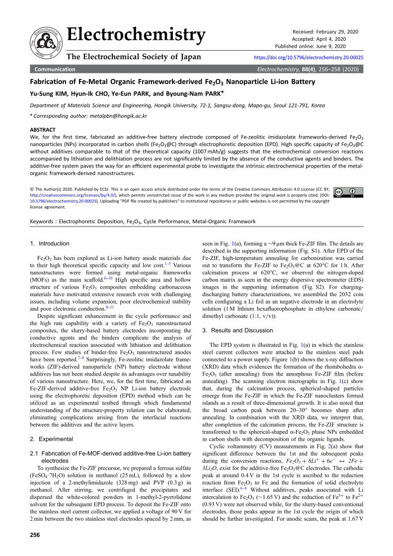
The EPD system is illustrated in Fig. 1(a) in which the stainlesssteel current collectors were attached to the stainless steel padsconnected to a power supply. Figure 1(b) shows the x-ray diffraction(XRD) data which evidences the formation of the rhombohedra A-Fe2O3 (after annealing) from the amorphous Fe-ZIF film (beforeannealing). The scanning electron micrographs in Fig. 1(c) showthat, during the calcination process, spherical-shaped particlesemerge from the Fe-ZIF in which the Fe-ZIF nanoclusters formedislands as a result of three-dimensional growth. It is also noted thatthe broad carbon peak between 20–30° becomes sharp afterannealing. In combination with the XRD data, we interpret that,after completion of the calcination process, the Fe-ZIF structure istransformed to the spherical-shaped A-Fe2O3 phase NPs embeddedin carbon shells with decomposition of the organic ligands.
Cyclic voltammetry (CV) measurements in Fig. 2(a) show thatsignificant difference between the 1st and the subsequent peaksduring the conversion reactions, Fe2O3 + 6Li+ + 6e¹ $ 2Fe +3Li2O, exist for the additive-free Fe2O3@C electrodes. The cathodicpeak at around 0.4V in the 1st cycle is ascribed to the reductionreaction from Fe2O3 to Fe and the formation of solid electrolyteinterface (SEI).6–8 Without additives, peaks associated with Liintercalation to Fe2O3 (³1.65V) and the reduction of Fe3+ to Fe2+
(0.93V) were not observed while, for the slurry-based conventionalelectrodes, those peaks appear in the 1st cycle the origin of whichshould be further investigated. For anodic scans, the peak at 1.67V
Electrochemistry Received: February 29, 2020
Accepted: April 4, 2020
Published online: June 9, 2020
The Electrochemical Society of Japan https://doi.org/10.5796/electrochemistry.20-00025
256
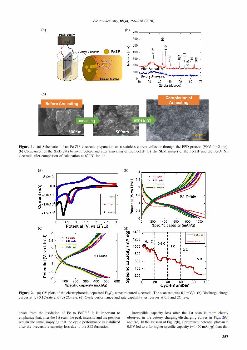
arises from the oxidation of Fe to FeO.6–8 It is important toemphasize that, after the 1st scan, the peak intensity and the positionremain the same, implying that the cycle performance is stabilizedafter the irreversible capacity loss due to the SEI formation.
Irreversible capacity loss after the 1st scan is more clearlyobserved in the battery charging/discharging curves in Figs. 2(b)and 2(c). In the 1st scan of Fig. 2(b), a prominent potential plateau at0.8V led to a far higher specific capacity (³1400mAh/g) than that
(a) (b)
(c)
Figure 1. (a) Schematics of an Fe-ZIF electrode preparation on a stainless current collector through the EPD process (90V for 2min).(b) Comparison of the XRD data between before and after annealing of the Fe-ZIF. (c) The SEM images of the Fe-ZIF and the Fe2O3 NPelectrode after completion of calcination at 620°C for 1 h.
(a) (b)
(c) (d)
Figure 2. (a) CV plots of the electrophoretic-deposited Fe2O3 nanostructured electrode. The scan rate was 0.1mV/s. (b) Discharge-chargecurves at (c) 0.1C-rate and (d) 2C-rate. (d) Cycle performance and rate capability test curves at 0.1 and 2C rate.
Electrochemistry, 88(4), 256–258 (2020)
257

in the subsequent cycles in which the potential plateaus arereproducibly observed close to 1V. The deviation of the peakposition between the CV and the potential profile plots may beattributed to the difference of the scan rate. From the observation, asignificant irreversible capacity loss in the subsequent cycles afterthe 1st cycle results from the decomposition of the SEI film as wellas reduction reaction from Fe2O3 to Fe, excluding the effect ofadditives on the electrochemical reactions. As the C-rate increasesfrom 0.1C to 5C in Fig. 2(d), the stabilized specific capacitydecrease was not significant compared with that of the slurry-basedelectrode systems containing additives. It is interesting to observethe fluctuation of the specific capacity with cycles. The fluctuationof the capacity was reproducibly observed in our binder-free batterysystem. From previous studies,12 the increase in the capacity withcycles is attributed to addition of the interfacial charge storage and/or the formation/decomposition of the electrolyte-derived surfacelayer during charging/discharging. It is also important to emphasizethat annealing process after the EPD process is critical in enhancingthe cycle performance. With the annealing process, the specificcapacity was, indeed, retained while the specific capacity dropped to50% of the initial value after tens of cycles without annealing (Datanot shown). We believe this is attributed to the difference in theinterfacial contact properties between the current collector and theactive layer resulting from the annealing process through whichelectrical contact can be enhanced.
In conclusion, we fabricated Fe-ZIF-derived additive-freeelectrophoretic-deposited Fe2O3 NP electrode embedding carbonshells and demonstrated a high specific capacity close to thetheoretical capacity without additives, suggesting that the additive-free system is a promising testbed to optimize the electrochemicalproperties through structural tuning of the Fe-ZIF at various reactionconditions.
Supporting Information
The Supporting Information is available on the website at DOI:https://doi.org/10.5796/electrochemistry.20-00025.
Acknowledgments
This research was supported by the Basic Science ResearchProgram through the National Research Foundation of Korea(NRF) funded by the Ministry of Education (NRF-2015R1A6A1A03031833, NRF-2019R1F1A1060042 and NRF-2020R1A2C1007258). This work was also supported by the 2019Hongik Faculty Research Support Fund.
References
1. M. Reddy, T. Yu, C.-H. Sow, Z. X. Shen, C. T. Lim, G. Subba Rao, and B.Chowdari, Adv. Funct. Mater., 17(15), 2792 (2007).
2. J. Liu, W. Zhou, L. Lai, H. Yang, S. H. Lim, Y. Zhen, T. Yu, Z. Shen, and J. Lin,Nano Energy, 2(5), 726 (2013).
3. T. R. Penki, S. Shivakumara, M. Minakshi, and N. Munichandraiah, Electrochim.Acta, 167, 330 (2015).
4. N. Wu, Y. R. Shi, C. Ma, X. Zhang, J.-M. Zhou, Y. Wei, H. Liu, Y. Yan, and H.-T.Liu, Mater. Lett., 238, 155 (2019).
5. G. Zhang, Y. Shi, H. Wang, L. Jiang, X. Yu, S. Jing, S. Xing, and P. Tsiakaras,J. Power Sources, 416, 118 (2019).
6. F. Zheng, M. He, Y. Yang, and Q. Chen, Nanoscale, 7(8), 3410 (2015).7. X. Li, L. Qiao, D. Li, X. Wang, W. Xie, and D. He, J. Mater. Chem. A, 1(21), 6400
(2013).8. J. Park, H. Yoo, and J. Choi, J. Power Sources, 431, 25 (2019).9. Y. Yang, Q. Liu, M. Cao, Q. Ju, H. Wang, R. Fu, H. Ji, and G. Yang, Appl. Surf.
Sci., 463, 322 (2019).10. Y. Cao, A.-Q. Zhang, H.-W. Luo, H.-L. Gao, J. Yan, Q.-Q. Yan, Y.-M. Liu, and Y.
Zhang, Inorg. Chem. Commun., 113, 107769 (2020).11. R. Liu, C. Zhang, Q. Wang, C. Shen, Y. Wang, Y. Dong, N. Zhang, and M. Wu,
J. Alloys Compd., 742, 490 (2018).12. H. Kim, W. Choi, J. Yoon, J. H. Um, W. Lee, J. Kim, J. Cabana, and W.-S. Yoon,
Chem. Rev., in press (2020).
Electrochemistry, 88(4), 256–258 (2020)
258