Embed Size (px)
Citation preview
Fabrication of Fe-Based Metallic Glass Particle Reinforced Al-Based
Composite Materials by Friction Stir Processing
Hidetoshi Fujii1;*, Yufeng Sun1, Koji Inada1, Youngsu Ji1, Yoshihiko Yokoyama2,Hisamichi Kimura2 and Akihisa Inoue2
1Joining and Welding Research Institute, Osaka University, Ibaraki 567-0047, Japan2Institute for Materials Research, Tohoku University, Sendai 980-8577, Japan
Fe72B14:4Si9:6Nb4 metallic glass particles and pure Fe particles were separately dispersed into the pure aluminum by the friction stirprocessing. The microstructure and mechanical properties of the stir zone were analyzed using XRD, SEM, TEM and Vickers hardness tests. Asa result, it was found that the Fe metallic glass and pure Fe particles can be uniformly dispersed into the pure aluminum by friction stir processingand the mechanical properties of the stir zone can be improved due to the formation of precipitates. [doi:10.2320/matertrans.M2011094]
(Received March 29, 2011; Accepted May 6, 2011; Published July 25, 2011)
Keywords: composite material, friction stir processing, bulk metallic glass
1. Introduction
Friction stir welding (FSW) is a welding technique that canplastically deform metallic materials and soften the materialsaround the probe due to the heat generated by the frictionbetween the rotating tool and work-pieces. The combinationof tool rotation and translation results in the movement ofmaterial from the front to the back of the probe, therebyproducing a welded joint in the solid state. This methodcan be used to refine the microstructure and improve themechanical properties of the welded material by heattreatment and severe plastic deformation. Friction stirprocessing (FSP) is a new technique for microstructuralmodification and was developed based on the basic principlesof FSW. Recently, the surface modification of materials byFSP has been intensively studied. It was reported that thefabrication of metal matrix composites (MMCs) uniformlydispersed with ceramic,1–6) fullerene,6,7) SiC8,9) and carbonnanotube10) particles has been successfully developed usingthe FSP. Since the process is performed below the meltingpoint of the materials, FSP has many advantages whenfabricating MMCs compared to other melting methods. Withthe rapid development of bulk metallic glasses, metallic glassparticles are attractive as reinforcement and have beensuccessfully used in the fabrication of Al-based MMCsbecause of their remarkable mechanical properties includinghigh yield strength and large elastic strain. In addition, theymay yield an improved interface between the matrix andparticles with respect to the conventional ceramic reinforce-ment.11–13)
In this study, the fabrication of an Al-based compositedispersed with Fe-based metallic glass particles was attempt-ed using the FSP method. The welding temperature of the Alalloy is between 400�C and 450�C during the FSW.14)
Accordingly, the Fe-based metallic glass particle was usedbecause its glass transition temperature15,16) is higher than thewelding temperature of the Al alloy and the oxidation doesnot easily occur. The base material was pure Al plates (1050-
H24). For comparison, the fabrication of Al-based compositedispersed with pure Fe particles was also attempted usingFSP.
2. Experimental Procedure
In this study, the base material was pure Al plates (1050-H24) with the dimensions of 300� 70� 5 mm3. TheFe72B14:4Si9:6Nb4 metallic glass particles17) with averagesize of 45 mm and pure Fe particles with average size of150 mm were used for the dispersion purpose. The toolsusually consist of a shoulder with a large diameter and aprobe with a small diameter, which is shown in Fig. 1(c). Thetool used in this study was made of SKD61 and had ashoulder of 15 mm diameter, a probe with 6 mm diameter and4.3 mm length with a 10� recessed shoulder surface. Theprobe was the screw-type and the tool was tilted by 3� duringthe process. For the dispersion process, a gap was intention-ally formed by placing 2 mm-thick shims between the twopure Al plates before the FSP was performed. Then, Fe-basedmetallic glass particles or pure Fe particles can be separatelyfilled into the gap, as shown in Fig. 1(a). In order to preventthe particles from flying off and to increase the filling rateof the powder, the FSP was first performed with only theshoulder (without probe), as shown in Fig. 1(b). By thismeans, the particles can be sealed beneath the sample surfaceby the metallic materials. Next, the FSP was repeated usingthe same welding conditions, however, with rotation toolshaving a 4.3 mm long probe, as shown in Fig. 1(c). This iscalled the first pass processing. In order to distribute the
Fig. 1 Schematic illustration of friction stir processing. (a) filling powder
into gap; (b) without probe; and (c) with probe (1st or 2nd pass).*Corresponding author, E-mail: [email protected]
Materials Transactions, Vol. 52, No. 8 (2011) pp. 1634 to 1640#2011 The Japan Institute of Metals
particles more uniformly in the stir zone, the FSP under thesame condition with that of the first pass processing wascarried out again and is called the second pass processing.
After the FSP, the phase identification and microstructuresof the dispersed specimens were examined by X-raydiffraction (XRD), scanning electron microscopy (SEM),transmission electron microscopy (TEM) and electronback-scattering diffraction (EBSD). The XRD analysis wasconducted (Bruker, AXS D8 DISCOVER) using Co-K�radiation. The stir zone of the dispersed specimen wasobserved by SEM (Hitachi SU-70). The samples for theTEM observations were prepared using twin-jet electrolyticpolishing in a solution with a mixed ratio of HNO3 :
CH3OH ¼ 7 : 3. The TEM observations were carried outusing a Hitachi H800T microscope at 200 kV. In addition, thesamples for the EBSD observations were prepared usingelectrolytic polishing in a solution with a mixed ratio ofHNO3 : CH3OH ¼ 7 : 3. The Vickers micro-hardness (HV)was measured using a digital tester (Akashi, AAV 501) withan applied load of 245.2 mN.
3. Results and Discussion
3.1 Dispersion of Fe-based metallic glass particles andpure Fe particles
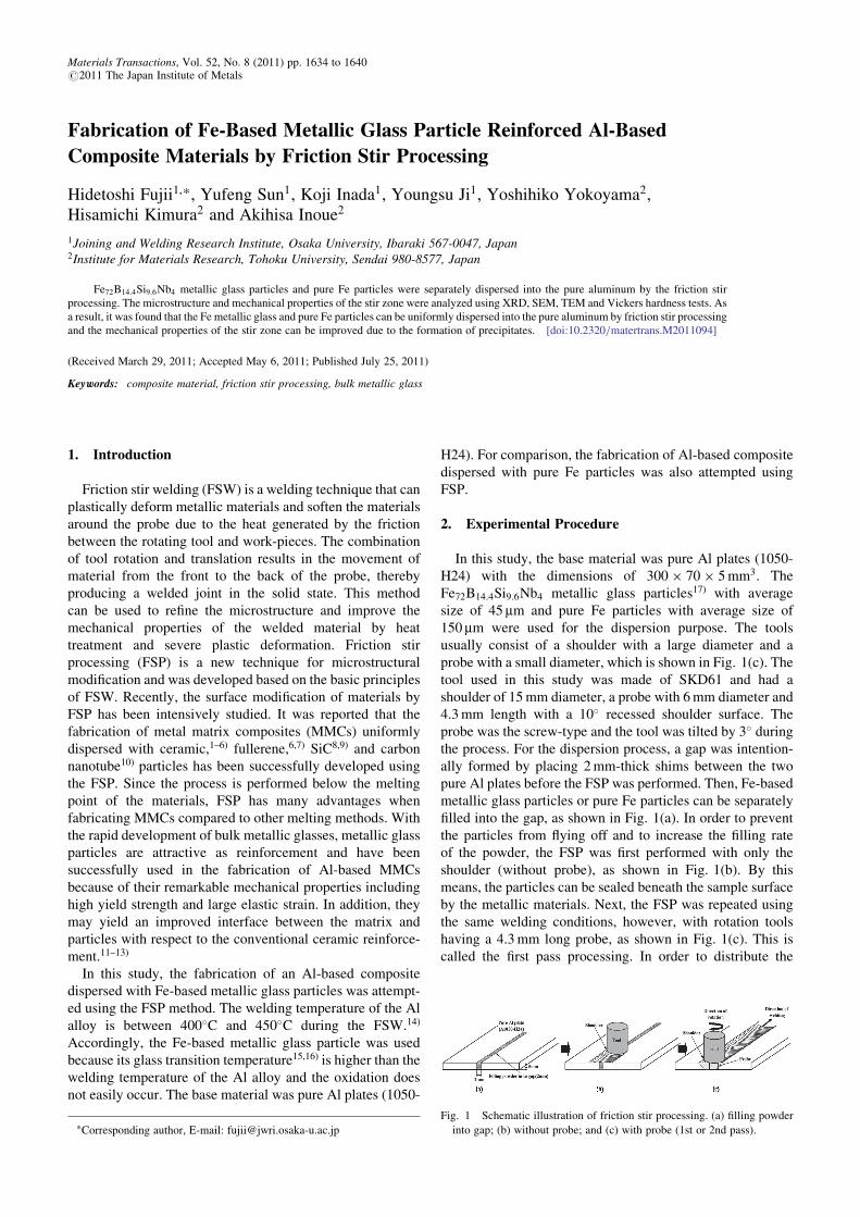
Figure 2 shows the SEM images of the stir zone of the
dispersed specimens after one pass processed at 1500 rpmand 100 mm/min. As shown in Fig. 2(a) and (b), the Fe-based metallic glass particles and pure Fe particles can beuniformly dispersed into the pure Al by FSP and no largedefects or cracks are observed in the stir zones. When the Fe-based metallic glass particles were dispersed into the pure Al,the size and shape of the particles are maintained, as shown inFig. 2(a). This indicates that the metallic glass particles werenot deformed or pulverized by the stirring of the tool due totheir high strength. However, when pure Fe particles weredispersed into the pure Al, the initial schistose state of theparticles was destroyed and the particle size was less than itsoriginal value of 150 mm. This is because the pure Fe particleshave been crushed by the rotation of the tools. In addition, athin layer was observed at the interface between the pure Aland Fe, as shown in Fig. 2(b). This indicates that a reactionbetween Al (base material) and Fe particles occurred duringthe FSP.
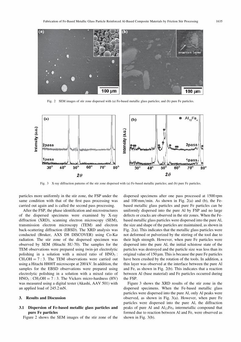
Figure 3 shows the XRD results of the stir zone in thedispersed specimens. When the Fe-based metallic glassparticles were dispersed into the pure Al, only Al peaks wereobserved, as shown in Fig. 3(a). However, when pure Feparticles were dispersed into the pure Al, the diffractionpeaks of pure Al and Al13Fe4 intermetallic compound thatformed due to reaction between Al and Fe, were observed asshown in Fig. 3(b).
Fig. 2 SEM images of stir zone dispersed with (a) Fe-based metallic glass particles; and (b) pure Fe particles.
Fig. 3 X-ray diffraction patterns of the stir zone dispersed with (a) Fe-based metallic particles; and (b) pure Fe particles.
Fabrication of Fe-Based Metallic Glass Particle Reinforced Al-Based Composite Materials by Friction Stir Processing 1635

3.2 Microstructure and mechanical propertiesFigure 4 shows the results of EBSD mapping obtained in
the stir zone of the dispersed specimens. As shown inFig. 4(a) and (b), the average grain sizes of the stir zonewithout particles and with particles are about 33 mm and17 mm, respectively. The coarsening of the Al grains wasretarded due to the pinning effect by addition of the Fe-basedmetallic glass particles.
Figure 5 shows the hardness distribution along the cross-sectional centerline in the stir zone of the dispersed speci-mens. As shown in Fig. 5, when the Fe-based metallic glassparticles are dispersed into the pure Al, the hardness ofthe stir zone slightly increased compared with that of thespecimen without particles.
3.3 Effect of pass number and travel speed on thehardness
In order to investigate the effect of the heat input on the
hardness and particle distribution of the Al FSP jointcontaining the Fe-based metallic glass, the FSP with varioustravel speeds were carried out. In addition, a second passFSP process was repeated to enhance the particles distribu-tion and hardness of the joints. Figure 6 shows the effectof the pass number and travel speed on the hardness of theFe-based metallic glass particle dispersed specimens. Duringthe FSP, the rotation speed was fixed at 1500 rpm. Generally,a low heat input is necessary during the FSP to preventcrystallization of the metallic glass and the hardnessreduction in the stir zone. However, the joint with the travel
Fig. 4 EBSD maps of the stir zone (a) without Fe-based metallic glass
particles; and (b) with Fe-based metallic glass particles.
Fig. 5 Effect of powder addition on hardness distribution on a cross section
perpendicular to the FSP direction.
Fig. 6 Effect of pass number and travel speed on the hardness of Fe metallic glass particle dispersed specimens.
1636 H. Fujii et al.
speed of 10 mm/min, corresponding to the highest heat input,shows higher hardness value. In addition, the hardness inthe stir zone shows a value higher than that of the base metal.The abnormal hardness increase of the sample with a highheat input requires further investigation. It is worth notingthat the pass number also shows a different influence on thehardness distribution of the sample when processed atdifferent travel speeds. When traveled at 100 mm/min, thehardness decreased after the 2 pass FSW process. In addition,for the sample welded at 10 mm/min, the hardness increasedafter the 2 pass FSW process. Therefore, a different harden-ing mechanism needs to be considered. For the sampleprocessed at other travel speeds, it shows no significantchanges in the hardness distribution of the stir zone.
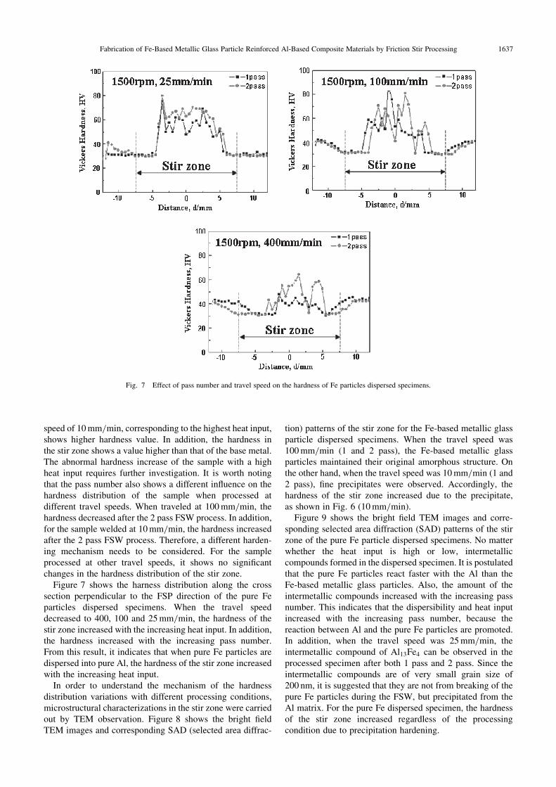
Figure 7 shows the harness distribution along the crosssection perpendicular to the FSP direction of the pure Feparticles dispersed specimens. When the travel speeddecreased to 400, 100 and 25 mm/min, the hardness of thestir zone increased with the increasing heat input. In addition,the hardness increased with the increasing pass number.From this result, it indicates that when pure Fe particles aredispersed into pure Al, the hardness of the stir zone increasedwith the increasing heat input.
In order to understand the mechanism of the hardnessdistribution variations with different processing conditions,microstructural characterizations in the stir zone were carriedout by TEM observation. Figure 8 shows the bright fieldTEM images and corresponding SAD (selected area diffrac-
tion) patterns of the stir zone for the Fe-based metallic glassparticle dispersed specimens. When the travel speed was100 mm/min (1 and 2 pass), the Fe-based metallic glassparticles maintained their original amorphous structure. Onthe other hand, when the travel speed was 10 mm/min (1 and2 pass), fine precipitates were observed. Accordingly, thehardness of the stir zone increased due to the precipitate,as shown in Fig. 6 (10 mm/min).
Figure 9 shows the bright field TEM images and corre-sponding selected area diffraction (SAD) patterns of the stirzone of the pure Fe particle dispersed specimens. No matterwhether the heat input is high or low, intermetalliccompounds formed in the dispersed specimen. It is postulatedthat the pure Fe particles react faster with the Al than theFe-based metallic glass particles. Also, the amount of theintermetallic compounds increased with the increasing passnumber. This indicates that the dispersibility and heat inputincreased with the increasing pass number, because thereaction between Al and the pure Fe particles are promoted.In addition, when the travel speed was 25 mm/min, theintermetallic compound of Al13Fe4 can be observed in theprocessed specimen after both 1 pass and 2 pass. Since theintermetallic compounds are of very small grain size of200 nm, it is suggested that they are not from breaking of thepure Fe particles during the FSW, but precipitated from theAl matrix. For the pure Fe dispersed specimen, the hardnessof the stir zone increased regardless of the processingcondition due to precipitation hardening.
Fig. 7 Effect of pass number and travel speed on the hardness of Fe particles dispersed specimens.
Fabrication of Fe-Based Metallic Glass Particle Reinforced Al-Based Composite Materials by Friction Stir Processing 1637
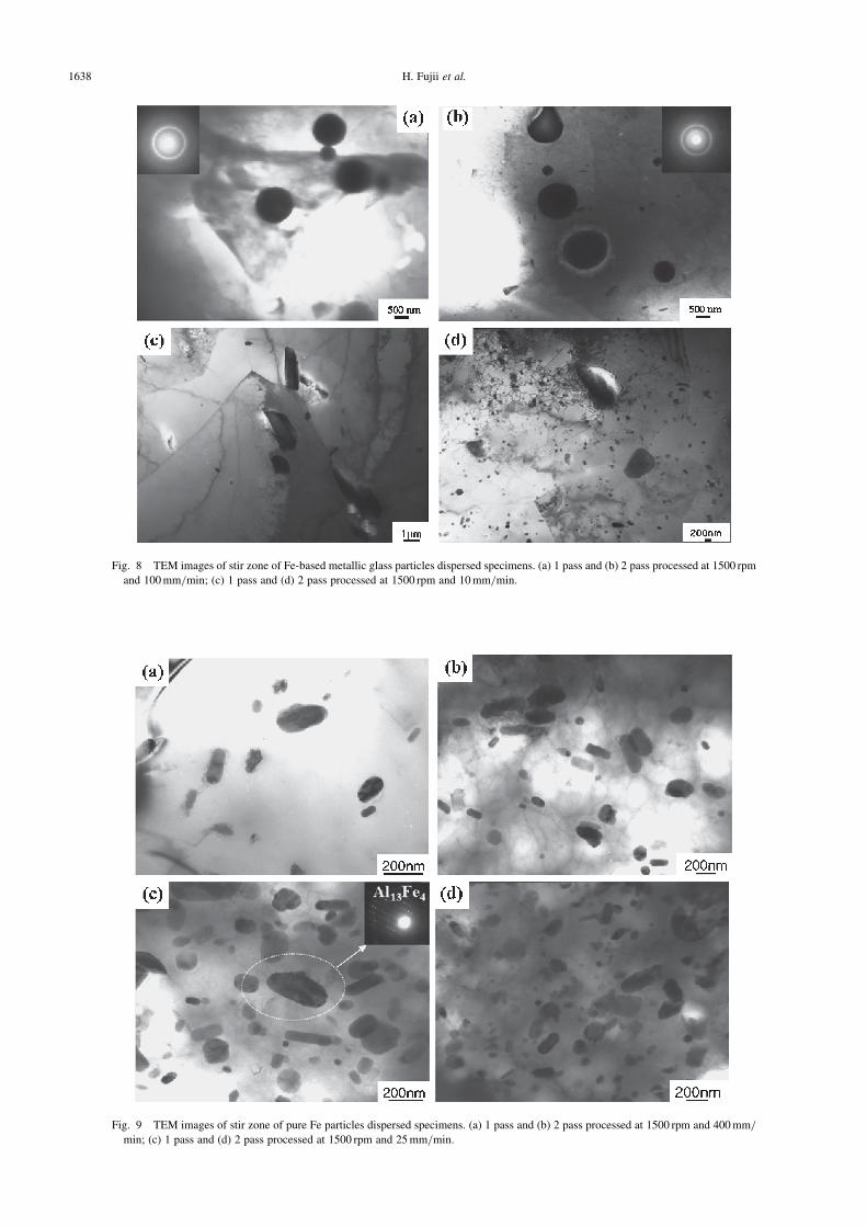
Fig. 8 TEM images of stir zone of Fe-based metallic glass particles dispersed specimens. (a) 1 pass and (b) 2 pass processed at 1500 rpm
and 100 mm/min; (c) 1 pass and (d) 2 pass processed at 1500 rpm and 10 mm/min.
Fig. 9 TEM images of stir zone of pure Fe particles dispersed specimens. (a) 1 pass and (b) 2 pass processed at 1500 rpm and 400 mm/
min; (c) 1 pass and (d) 2 pass processed at 1500 rpm and 25 mm/min.
1638 H. Fujii et al.
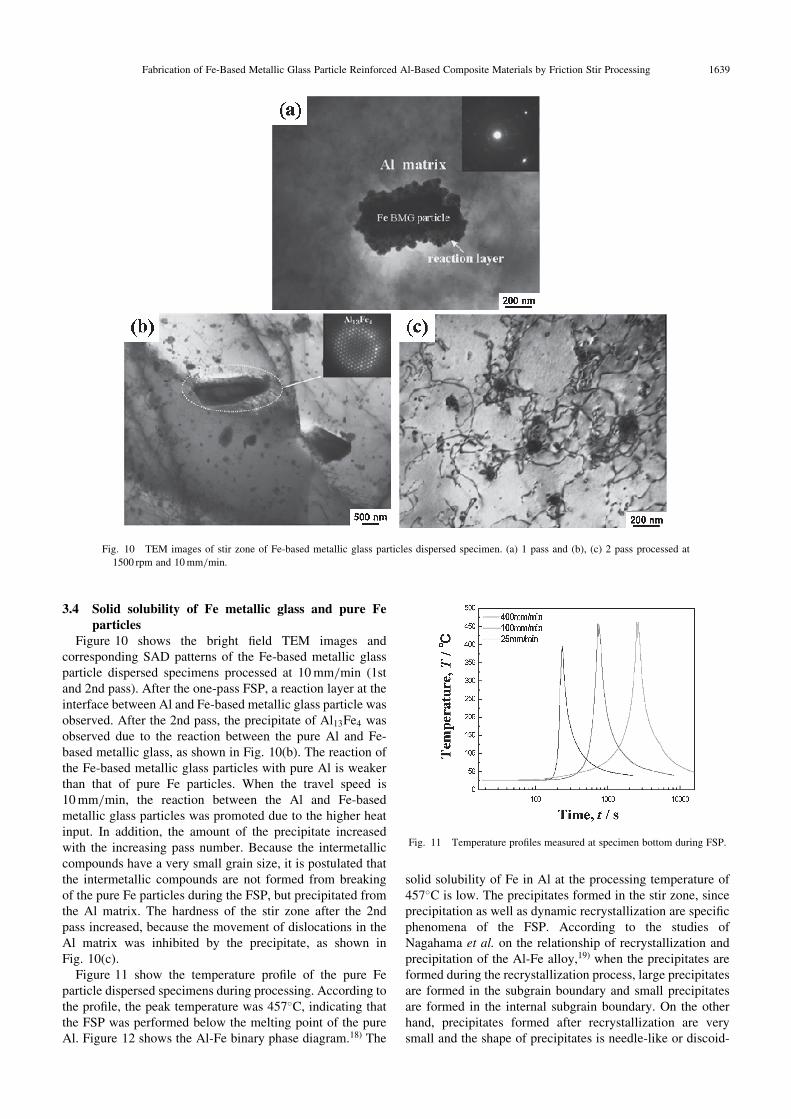
3.4 Solid solubility of Fe metallic glass and pure Feparticles
Figure 10 shows the bright field TEM images andcorresponding SAD patterns of the Fe-based metallic glassparticle dispersed specimens processed at 10 mm/min (1stand 2nd pass). After the one-pass FSP, a reaction layer at theinterface between Al and Fe-based metallic glass particle wasobserved. After the 2nd pass, the precipitate of Al13Fe4 wasobserved due to the reaction between the pure Al and Fe-based metallic glass, as shown in Fig. 10(b). The reaction ofthe Fe-based metallic glass particles with pure Al is weakerthan that of pure Fe particles. When the travel speed is10 mm/min, the reaction between the Al and Fe-basedmetallic glass particles was promoted due to the higher heatinput. In addition, the amount of the precipitate increasedwith the increasing pass number. Because the intermetalliccompounds have a very small grain size, it is postulated thatthe intermetallic compounds are not formed from breakingof the pure Fe particles during the FSP, but precipitated fromthe Al matrix. The hardness of the stir zone after the 2ndpass increased, because the movement of dislocations in theAl matrix was inhibited by the precipitate, as shown inFig. 10(c).
Figure 11 show the temperature profile of the pure Feparticle dispersed specimens during processing. According tothe profile, the peak temperature was 457�C, indicating thatthe FSP was performed below the melting point of the pureAl. Figure 12 shows the Al-Fe binary phase diagram.18) The
solid solubility of Fe in Al at the processing temperature of457�C is low. The precipitates formed in the stir zone, sinceprecipitation as well as dynamic recrystallization are specificphenomena of the FSP. According to the studies ofNagahama et al. on the relationship of recrystallization andprecipitation of the Al-Fe alloy,19) when the precipitates areformed during the recrystallization process, large precipitatesare formed in the subgrain boundary and small precipitatesare formed in the internal subgrain boundary. On the otherhand, precipitates formed after recrystallization are verysmall and the shape of precipitates is needle-like or discoid-
Fig. 10 TEM images of stir zone of Fe-based metallic glass particles dispersed specimen. (a) 1 pass and (b), (c) 2 pass processed at
1500 rpm and 10 mm/min.
Fig. 11 Temperature profiles measured at specimen bottom during FSP.
Fabrication of Fe-Based Metallic Glass Particle Reinforced Al-Based Composite Materials by Friction Stir Processing 1639
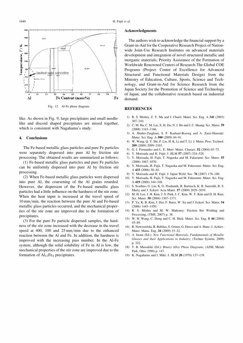
like. As shown in Fig. 9, large precipitates and small needle-like and discoid shaped precipitates are mixed together,which is consistent with Nagahama’s study.
4. Conclusions
The Fe-based metallic glass particles and pure Fe particleswere separately dispersed into pure Al by friction stirprocessing. The obtained results are summarized as follows:
(1) Fe-based metallic glass particles and pure Fe particlescan be uniformly dispersed into pure Al by friction stirprocessing.
(2) When Fe-based metallic glass particles were dispersedinto pure Al, the coarsening of the Al grains retarded.However, the dispersion of the Fe-based metallic glassparticles had a little influence on the hardness of the stir zone.When the heat input is increased at the travel speed of10 mm/min, the reaction between the pure Al and Fe-basedmetallic glass particles occurred, and the mechanical proper-ties of the stir zone are improved due to the formation ofprecipitates.
(3) For the pure Fe particle dispersed samples, the hard-ness of the stir zone increased with the decrease in the travelspeed at 400, 100 and 25 mm/min due to the enhancedreaction between the Al and Fe. In addition, the hardness isimproved with the increasing pass number. In the Al-Fesystem, although the solid solubility of Fe in Al is low, themechanical properties of the stir zone are improved due to theformation of Al13Fe4 precipitates.
Acknowledgments
The authors wish to acknowledge the financial support by aGrant-in-Aid for the Cooperative Research Project of Nation-wide Joint-Use Research Institutes on advanced materialsdevelopment and integration of novel structured metallic andinorganic materials; Priority Assistance of the Formation ofWorldwide Renowned Centers of Research-The Global COEPrograms (Project: Center of Excellence for AdvancedStructural and Functional Materials Design) from theMinistry of Education, Culture, Sports, Science and Tech-nology, and Grant-in-Aid for Science Research from theJapan Society for the Promotion of Science and Technologyof Japan; and the collaborative research based on industrialdemand.
REFERENCES
1) R. S. Mishra, Z. Y. Ma and I. Charit: Mater. Sci. Eng. A 341 (2003)
307–310.
2) C. M. Hu, C. M. Lai, X. H. Du, N. J. Ho and J. C. Huang: Scr. Mater. 59
(2008) 1163–1166.
3) A. Shafiei-Zarghani, S. F. Kashani-Bozorg and A. Zarei-Hanzaki:
Mater. Sci. Eng. A 500 (2009) 84–91.
4) W. Wang, Q. Y. Shi, P. Liu, H. K. Li and T. Li: J. Mater. Proc. Technol.
209 (2009) 2099–2103.
5) G. J. Fernandez and L. E. Murr: Mater. Charact. 52 (2004) 65–75.
6) Y. Morisada and H. Fujii: J. JILM 57 (2007) 524–528.
7) Y. Morisada, H. Fujii, T. Nagaoka and M. Fukusumi: Scr. Mater. 55
(2006) 1067–1070.
8) Y. Morisada, H. Fujii, T. Nagaoka and M. Fukusumi: Mater. Sci. Eng.
A 433 (2006) 50–54.
9) Y. Morisada and H. Fujii: J. Japan Weld. Soc. 76 (2007) 176–180.
10) Y. Morisada, H. Fujii, T. Nagaoka and M. Fukusumi: Mater. Sci. Eng.
A 419 (2006) 344–348.
11) S. Scudino, G. Liu, K. G. Prashanth, B. Bartusch, K. B. Surreddi, B. S.
Murty and J. Eckert: Acta Mater. 57 (2009) 2029–2039.
12) M. H. Lee, J. H. Kim, J. S. Park, J. C. Kim, W. T. Kim and D. H. Kim:
Scr. Mater. 50 (2004) 1367–1371.
13) P. Yu, K. B. Kim, J. Das, F. Baier, W. Xu and J. Eckert: Scr. Mater. 54
(2006) 1445–1450.
14) R. S. Mishra and M. W. Mahoney: Friction Stir Welding and
Processing, (TMS, 2007) p. 38.
15) W. H. Wang, C. Dong and C. H. Shek: Mater. Sci. Eng. R 44 (2004)
45–89.
16) R. Nowosielski, R. Babilas, S. Griner, G. Dercz and A. Hanc: J. Achiev.
Mater. Manu. Eng. 34 (2009) 15–22.
17) A. Inoue (Ed.): New Functional Matreials, Fundamentals of Metallic
Glasses and their Applications to Industry, (Techno System, 2009)
p. 322.
18) T. B. Massalski (Ed.): Binary Alloy Phase Diagrams, (ASM, Metals
Park, Ohio 1990) p. 147.
19) K. Nagahama and I. Miki: J. JILM 20 (1970) 137–139.
Fig. 12 Al-Fe phase diagram.
1640 H. Fujii et al.