Embed Size (px)
Citation preview
FABRICATION OF ABRASIVE JET MACHINE
A THESIS SUBMITTED IN PARTIAL FULFILLMENT OF THE
REQUIREMENTS FOR THE DEGREE OF
Bachelor of Technology
In
Mechanical Engineering
By
SHATABDI BISWAL
Roll No. – 109ME0363
Under the guidance of
Prof. C. K. BISWAS
Department of Mechanical Engineering National Institute of Technology
Rourkela 2013
FABRICATION OF ABRASIVE JET MACHINE
A THESIS SUBMITTED IN PARTIAL FULFILLMENT OF THE
REQUIREMENTS FOR THE DEGREE OF
Bachelor of Technology
In
Mechanical Engineering
By
SHATABDI BISWAL
Roll No. - 109ME0363
Under the guidance of
Prof. C. K. BISWAS
Department of Mechanical Engineering National Institute of Technology
Rourkela 2013
i
National Institute of Technology
Rourkela
CERTIFICATE
This is to certify that the thesis entitled “FABRICATION OF ABRASIVE JET MACHINE”
Submitted by MR. SHATABDI BISWAL in partial fulfillment of the requirements for the
award of Bachelor of technology Degree in Mechanical Engineering at the National Institute of
Technology, Rourkela (Deemed University) is an authentic work carried out by him under my
supervision and guidance. To the best of my knowledge, the matter embodied in the thesis has
not been submitted to any other University / Institute for the award of any Degree or Diploma.
DATE:
PLACE: Prof. C. K. BISWAS
NATIONAL INSTITUTE OF TECHNOLOGY
ROURKELA, 769008
ii
National Institute of Technology
Rourkela
ACKNOWLEDGEMENT
I deem it a privilege to have been a student of Mechanical Engineering stream in National
Institute of Technology, Rourkela. I take this opportunity to express my gratitude to all those
who motivated, encouraged and helped me in the project work. I’m grateful to my supervisor,
Prof. C.K. Biswas, for his kind support, guidance and encouragement throughout the project
work, also for introducing to me this topic, which has been very interesting and has given us
great insight to the future work on this area. I am also thankful to Mr. Juktiprasad Parhi, Mr.
Sailesh Dewangan, and Mr. Kunal Nayak, Mr. Arvind khuntia for their support and
encouragement. We would like to take the chance to express our appreciation to our family
members. Their continuous love and support gave us the strength for pursuing our dream.
Special thanks to our friends and other members of the department for being so supportive and
helpful in every possible way.
Place- Rourkela Shatabdi Biswal
Date- Roll No ‐ 109ME0363
Department of Mechanical Engineering
National Institute of Technology, Rourkela
iii
CONTENTS
Certificate
Acknowledgement
List of figures
List of tables
Abstract
1. INTRODUCTION
1.1 Abrasive jet machining principle
1.2 Equipment
1.3 Variables affecting performance
1.4 Operating characteristics
1.5 Advantages and disadvantages
1.6 Uses and applications
2. LITERATURE REVIEW
3. DESIGN AND FABRICATION OF FUNCTIONAL SUB-SYSTEMS
3.1 Design methodology
3.2 Machining chamber
3.2.1 Air tight chamber
3.2.2 Work holding device
3.2.3 Door opening and closing system
3.2.4 Abrasive drainage system
3.3 Abrasive delivery system
3.3.1 Compressor
3.3.2 Mixing chamber
3.3.3 Vibrating assembly
3.3.4 FRL unit
3.3.5 Nozzle and nozzle holder
3.3.6 Piping systems
1-5
6-9
10
10-15
16-21
iv
3.4 Machine frame and X-Y-Z travel system
3.4.1 Machine frame
3.4.2 X-Y-Z travel system
3.5 Machine automation
3.5.1 Stepper motors
3.5.2 Controller and driver
3.6 TOTAL ASSEMBLY
3.7 COST ESTIMATION
4. CONCLUSION
5. REFERENCES
6. BIBLIOGRAPHY
21-22
22-24
25-27
28
29
30-31
32
v
List of figures:-
Fig. No Title Page no.
1 Layout of abrasive jet machine 1
2 Operating characteristics 4
3 SOD vs MRR 5
4 Machining chamber front view 11
5 Machining chamber top view 12
6 Fabricated machining chamber 12
7 Making air tight chamber by using polythene sheet 14
8 Work holding device 15
9 Magnetic clamp 16
10 Door opening mechanism 16
11 Abrasive drainage system 16
12 Mixing chamber 17
13 Vibrating assembly 18
14 Pressure regulator working 19
15 Abrasive nozzle operation 20
16 Nozzle holder 21
17 Braided hose pipe Structure 22
18 X-Y table 23
19 Controller and remote 25
20 Total assembly front view 26
21 Side view 27
22 Isometric view 28
vi
List of tables:-
Table no. Title Page no.
1 Performance parameters standard values 3
2 Materials for machining chamber 13
3 Steeper motor specifications 25
4 Cost estimation 29
vii
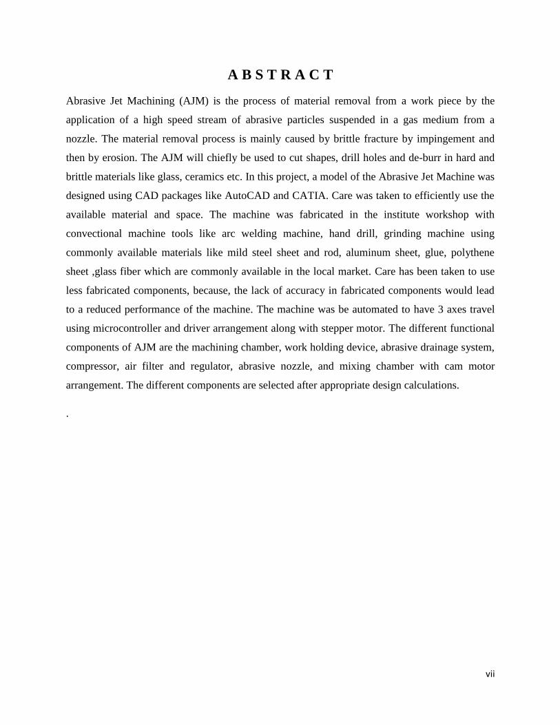
A B S T R A C T
Abrasive Jet Machining (AJM) is the process of material removal from a work piece by the
application of a high speed stream of abrasive particles suspended in a gas medium from a
nozzle. The material removal process is mainly caused by brittle fracture by impingement and
then by erosion. The AJM will chiefly be used to cut shapes, drill holes and de-burr in hard and
brittle materials like glass, ceramics etc. In this project, a model of the Abrasive Jet Machine was
designed using CAD packages like AutoCAD and CATIA. Care was taken to efficiently use the
available material and space. The machine was fabricated in the institute workshop with
convectional machine tools like arc welding machine, hand drill, grinding machine using
commonly available materials like mild steel sheet and rod, aluminum sheet, glue, polythene
sheet ,glass fiber which are commonly available in the local market. Care has been taken to use
less fabricated components, because, the lack of accuracy in fabricated components would lead
to a reduced performance of the machine. The machine was be automated to have 3 axes travel
using microcontroller and driver arrangement along with stepper motor. The different functional
components of AJM are the machining chamber, work holding device, abrasive drainage system,
compressor, air filter and regulator, abrasive nozzle, and mixing chamber with cam motor
arrangement. The different components are selected after appropriate design calculations.
.
B.Tech thesis 2013
1
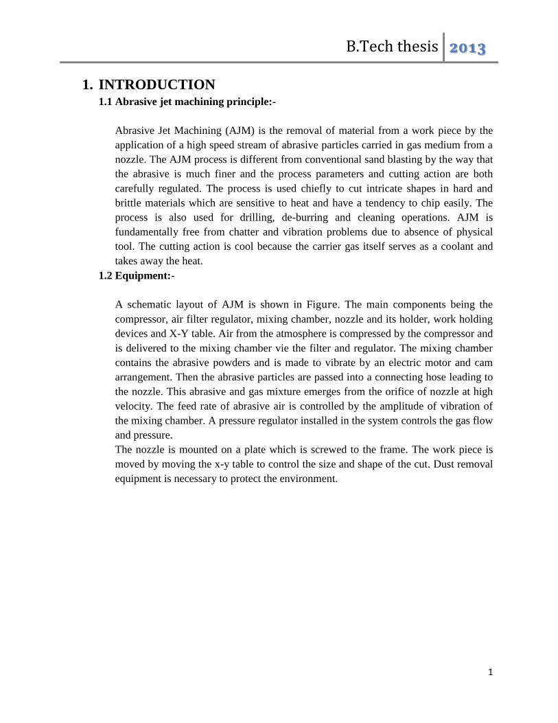
1. INTRODUCTION 1.1 Abrasive jet machining principle:-
Abrasive Jet Machining (AJM) is the removal of material from a work piece by the
application of a high speed stream of abrasive particles carried in gas medium from a
nozzle. The AJM process is different from conventional sand blasting by the way that
the abrasive is much finer and the process parameters and cutting action are both
carefully regulated. The process is used chiefly to cut intricate shapes in hard and
brittle materials which are sensitive to heat and have a tendency to chip easily. The
process is also used for drilling, de-burring and cleaning operations. AJM is
fundamentally free from chatter and vibration problems due to absence of physical
tool. The cutting action is cool because the carrier gas itself serves as a coolant and
takes away the heat.
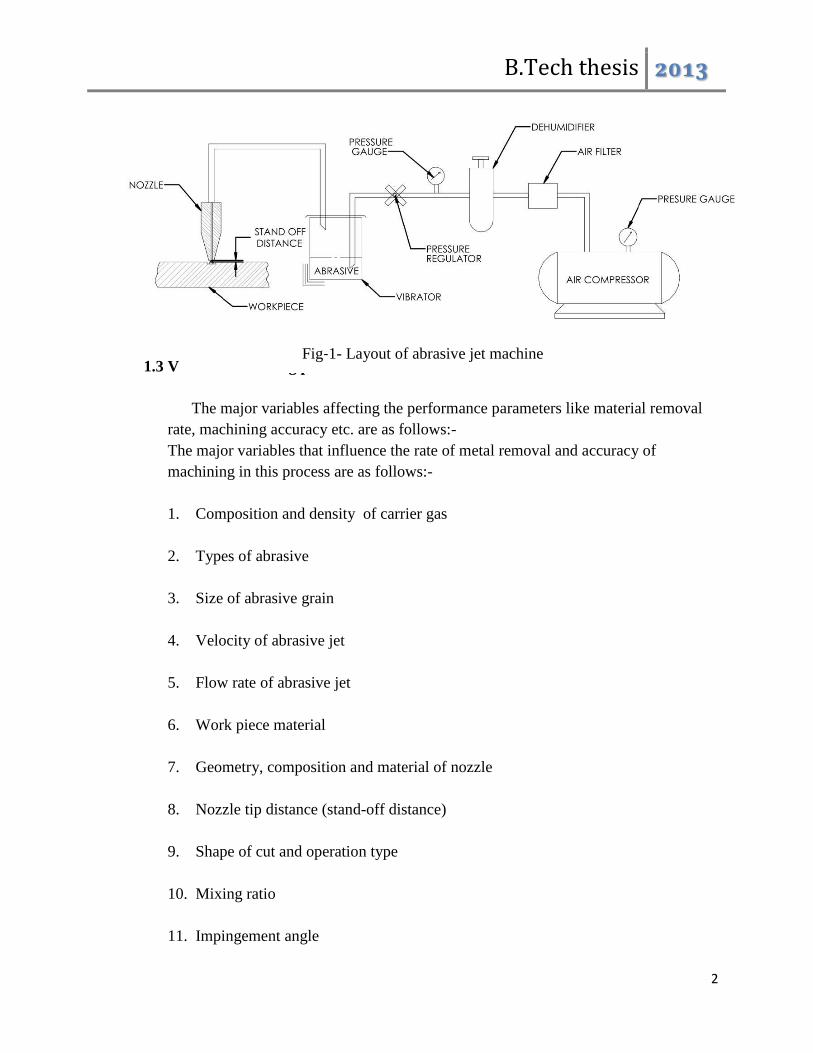
1.2 Equipment:-
A schematic layout of AJM is shown in Figure. The main components being the
compressor, air filter regulator, mixing chamber, nozzle and its holder, work holding
devices and X-Y table. Air from the atmosphere is compressed by the compressor and
is delivered to the mixing chamber vie the filter and regulator. The mixing chamber
contains the abrasive powders and is made to vibrate by an electric motor and cam
arrangement. Then the abrasive particles are passed into a connecting hose leading to
the nozzle. This abrasive and gas mixture emerges from the orifice of nozzle at high
velocity. The feed rate of abrasive air is controlled by the amplitude of vibration of
the mixing chamber. A pressure regulator installed in the system controls the gas flow
and pressure.
The nozzle is mounted on a plate which is screwed to the frame. The work piece is
moved by moving the x-y table to control the size and shape of the cut. Dust removal
equipment is necessary to protect the environment.
B.Tech thesis 2013
2
1.3 Variables affecting performance:-
The major variables affecting the performance parameters like material removal
rate, machining accuracy etc. are as follows:-
The major variables that influence the rate of metal removal and accuracy of
machining in this process are as follows:-
1. Composition and density of carrier gas
2. Types of abrasive
3. Size of abrasive grain
4. Velocity of abrasive jet
5. Flow rate of abrasive jet
6. Work piece material
7. Geometry, composition and material of nozzle
8. Nozzle tip distance (stand-off distance)
9. Shape of cut and operation type
10. Mixing ratio
11. Impingement angle
Fig‐1- Layout of abrasive jet machine
B.Tech thesis 2013
3
Sl no. Parameters General values
1 Abrasive material Al2O3 / SiC / glass beads
2 Abrasive shapes irregular / spherical
3 Abrasive size 10-50 μm
4 Mass flow rate 2 ~ 20 gm/min
5 Carrier gas Composition Air, CO2, N2
6 Air jet velocity 500 ~ 700 m/s
7 Pressure 2-10 bars
8 Flow rate 5-30lpm
9 Mixing ratio – mass flow
ratio of abrasive to gas Mabr/Mgas
10 Stand-off distance 0.5 ~ 5 mm
11 Impingement Angle 600 ~ 900
12 Nozzle⎯ Material WC / sapphire
Table-1- Performance parameters standard values
B.Tech thesis 2013
4
13 Diameter 0.2 ~ 0.8 mm
14 Life 10 ~ 300 hours
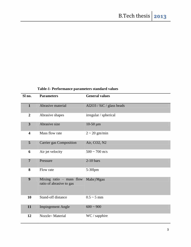
1.4 Operating characteristics:-
The main performance measuring parameters of AJM are as follows:-
1. The material removal rate in gm/mm^3 ,
2. The accuracy and surface finish of the machined surface
3. The nozzle wear rate
Fig.2-Operacting characteristics
B.Tech thesis 2013
5
As seen in the graph MRR increases with increase in abrasive flow rate due to greater
number of particles striking per unit time. Also MRR increases with increase in mixing ratio
which is the ratio of weight of particles to that of the weight of air. But further increase in mixing
ratio decreases MRR due to the fact that the volume of carries gas which is responsible for the
high velocity is reduced. MRR increases with increase in abrasive flow rate when mixing ratio is
constant. The MRR increases with increase in gas pressure as the particles will strike with
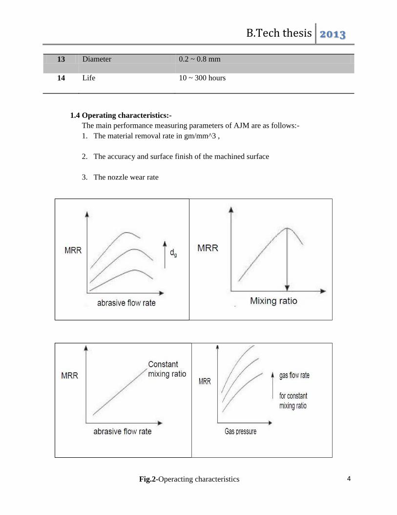
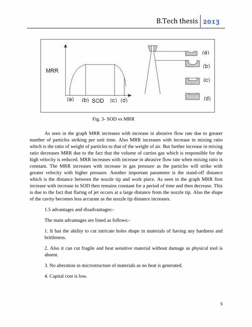
greater velocity with higher pressure. Another important parameter is the stand-off distance
which is the distance between the nozzle tip and work piece. As seen in the graph MRR first
increase with increase in SOD then remains constant for a period of time and then decrease. This
is due to the fact that flaring of jet occurs at a large distance from the nozzle tip. Also the shape
of the cavity becomes less accurate as the nozzle tip distance increases.
1.5 advantages and disadvantages:-
The main advantages are listed as follows:-
1. It has the ability to cut intricate holes shape in materials of having any hardness and
brittleness.
2. Also it can cut fragile and heat sensitive material without damage as physical tool is
absent.
3. No alteration in microstructure of materials as no heat is generated.
4. Capital cost is low.
Fig. 3- SOD vs MRR
B.Tech thesis 2013
6
The major disadvantages include:-
1. Material removal rate is low and hence its application is limited to small scale
machining.
2. Stray strings can occur and so its application is limited.
3. Embedding of the abrasive particles in the work piece surface may occur while
machining softer material.
4. The abrasive material may accumulate at nozzle and fail the process if moisture is
contained in the air.
5. It cannot be used to drill blind holes.
6. Tapering occurs due to flaring of the jet
7. Risk to environment is higher
1.6 Uses and applications:-
The major area of application of AJM process is in the machining of brittle
materials and heat sensitive materials like quartz glass, sapphire, mica and ceramics
semiconductor materials. It is also used in countering, drilling, cutting slot, thin sections,
, de-burring, for producing integrate shapes in hard and brittle materials. It is often used
for cleaning and polishing of plastics like nylon. Delicate cleaning, such as removal of
smudges from antique documents, is also possible with this method. Micro machining is
possible in brittle materials by this method.
B.Tech thesis 2013
7
2. LITERATURE REVIEW:-
The literature study of Abrasive Jet Machine reveals that the machining process was
started a few decades ago. Till date there has been a complete and detailed experiment
and theoretical study on this process. Most of the studies argue over the hydrodynamic
characteristics of abrasive jets, hence determining the influence of all operational
variables on the process usefulness including abrasive size ,kinds and concentration,
impact speed and angle of strike. Other papers found new problems concerning carrier
gas typologies, nozzle shape, size and wear rate, jet velocity and pressure, stand‐off‐
distance (SOD). These papers state the overall process performance in terms of material
removal rate(MRR), geometrical tolerances and surface finish of work pieces, as well as
in terms of nozzle wear rate or nozzle life. Finally, there are several significant and
important papers which focus on either leading process mechanisms in machining of both
ductile and brittle materials, or on the development of systematic experimental‐statistical
approaches and artificial neural networks to predict the relationship between the settings
of operational variables and the machining rate and accuracy in surface finishing. Some
researchers have also done the CFD simulation of machining process.
Abrasive Water Jet (AWJ) turning is a technology that still tries to find its position field
of application where it can be economically viable. But a particular application of AWJ
turning has proved its superior technological and economical competency, i.e. profiling
and dressing of grinding wheels. Starting from the theoretical considerations, the main
operating parameters of AWJ turning are identified and included in a method to generate
various profiles of grinding wheels by means of tangential movement of the jet column.
Roughing in single pass to concave or convex geometries (experimented depth of cuts <
30 mm), generation of thin walls/slots (thickness < 2 mm, depth > 430 mm) and intricate
profile (e.g. succession of tight radii) on a variety of grinding wheels show the capability
of AWJ turning to fulfill the requirements of this niche application .
The machining process produces no heat and hence changes in microstructure or strength
of the surface is less likely to occur. The air itself acts as a coolant and hence AJM
process is regarded as damage free micromachining method. The fracture toughness and
hardness of the target materials are critical parameters affecting the material removal rate
in AJM. However, their effect on the machinability varied greatly with the employed
abrasives particles.
In recent years abrasive jet machining has been gaining increasing acceptability for de-
burring applications. The influence of abrasive jet de-burring process parameters is not
known clearly. AJM de-burring has the advantage over manual de-burring method that
generates edge radius automatically. This increases the quality of the de-burred
components. The burr removal process and the generation of a convex edge vary as a
function of the parameters like jet height and impingement angle, when SOD is fixed.
B.Tech thesis 2013
8
The effect of other parameters, such as nozzle pressure, mixing ratio and abrasive size are
less significant. The SOD was found to be the critical factor on the size of the radius
generated at the edges. The size of the generated edge radius was found to be restricted to
the burr root thickness.
(Ref‐4) In integration manufacturing technology abrasive jet finishing combined with
grinding gives rise to a precision finishing process, in which slurry of abrasive and liquid
solvent is introduced to grinding area between wheel and work surface under no radial
feed . The particles are driven and energized by the rotating grinding wheel and liquid
pressure and increased slurry speed between grinding wheel and work surface
accomplishes micro removal finishing.
Abrasive water-jet machines are becoming more widely used in mechanical machining.
These machines offer great advantages in machining complex geometrical parts in almost
every material. This unique ability to machine hard‐to‐machine materials, along with
advancements in both the hardwares and softwares used in water-jet machining is the
reason behind the technology to spread and become more widely used. Gradual
developments in high pressure pumps which provide more hydraulic power at the cutting
head greatly increase the cutting performance of the machine. Analysis of the economic
and technical factors has been done by various researchers. Those technological
advancements in applying both higher power machining and intelligent software control
have significantly improved the overall performance of the abrasive water-jet machining
process, thus widening the scope of applications of this promising technology.
(Ref‐10) Quality of the surface produced during abrasive water jet machining of
aluminum has been investigated in recent years. The abrasive used was garnet of mesh
size 80. The variables were stand‐off distance (SOD) of the nozzle from the work piece
surface; feed rate and jet pressure. The evaluating criteria width of cut, taper of the cut
slot and work surface roughness. It was found that in order to reduce the width of cut; the
nozzle should be placed close to the work piece surface. Increase in jet pressure effects in
widening of the cut both at the top and at exit of the jet from the work piece. However,
the width of cut at the bottom (exit) was always found to be larger than that at the top (at
a stand‐off distance (SOD) of 3 mm and the work feed rate of 15 mm/ min). It was found
that the taper of cut gradually reduces with increase in stand‐off distance and was close to
zero at the stand‐off distance of 4 mm (at a jet pressure of 30 ksi and a work feed rate of
15 mm/min). The feed rate of the work should be kept within 40 mm/ min (at the jet
pressure of 30 ksi and the stand‐off distance of 3 mm), because a feed rate beyond 40
mm/min results in sharp rise in taper angle. The jet pressure does not show significant
effect on the taper angle within the range of feed rate show strong influence on the
roughness of the machined surface. Hence stand‐off distance should be kept within 3 mm
(at a jet pressure of 30 ksi and a work feed rate of 15 mm min‐1) and the work feed rate

B.Tech thesis 2013
9
should be kept within 30 mm/min (at a jet pressure of 30 ksi and a stand‐off distance of 3
mm) in order to have a good surface finish, since beyond those values of the parameters
the roughness of the machined surface rises sharply. Increase in jet pressure shows
positive effect in terms of smoothness of the machined surface. With increase in jet
pressure, the surface roughness decreases (at a stand‐off distance of 3mm and work feed
of 15 mm/min). This is due to fragmentation of the abrasive particles into smaller sizes at
a higher pressure and due to the fact that smaller particles produce smoother surface. So
within the jet pressure considered, the work surface is smoother near the top surface and
gradually it becomes rougher at depths.
(Ref‐6) Computational fluid dynamics (CFD) simulation of the formation and discharge
process of an air‐water flow in an abrasive water-jet (AWJ) head is presented by Umberto
Prisco & Maria Carmina D'Onofrio. Numerical simulations have been made using the
commercial code Fluent® 6.3 by Ansys software. Dynamic flow characteristics inside the
AWJ head and downstream from the nozzle has been simulated under turbulent, steady
state, two‐phase flow conditions. The final aim is to gain fundamental knowledge of the
high velocity flow dynamic features that could affect the quality of the jet, such as the
pressure and velocity distributions in different parts of the jet and at the outlet.
(Ref‐9) Experiments have been conducted on effect of jet pressure, abrasive flow rate
and work feed rate on smoothness of the surface produced by AWJM of carbide of grade
P25. Carbide of grade P25 is extremely hard and thus cannot be machined by
conventional techniques. The abrasive used in experiments was garnet of mesh size 80. It
was tried to cut carbide with low and medium level of abrasive flow rate, but the jet
failed to cut carbide as it is too hard and very high energy is required. Minimum abrasive
flow rate that made it possible to cut carbide efficiently was 135 g min‐1. With increase
in jet pressure the surface becomes smoother due to higher kinetic energy of the abrasives
particles. But the surface near the jet entrance is smoother and the surface gradually
becomes rougher downstream and is the roughest near the exit of jet. Increase in abrasive
flow rate also makes the surface smoother which is due to the fact that availability of
higher number of cutting edges per unit area per unit time. Feed rate didn’t show
substantial influence on the machined surface, but it was found that the surface roughness
increases hugely near the jet entrance.
The study of the results of machining under various operating conditions approves that a
commercial AJM machine was used, with nozzles hiving diameter ranging from 0.45 to
0.65 mm, the nozzle materials being either tungsten carbide or sapphire, which have high
tool lives. SIC and aluminum oxides were the two abrasives used. Other parameters
studied were standoff distance (5–10 mm), spray angles (60° and 90°) and pressures (5
and 7 bars) for materials like ceramics, glass, and electro‐discharge machined (EDM) die
B.Tech thesis 2013
10
steel. The holes drilled by AJM may not be circular and cylindrical but almost elliptical
and bell mouthed in shape. High material removal rate conditions may not necessarily r
small narrow clean‐cut machined areas.
(Ref‐5) Studies show that AJM is a good micro‐machining method for ceramics. The
machinability during the AJM process can be associated to that given by the established
models of solid particle erosion, in which the material removal is assumed to initiate in
the ideal crack formation system. However, it was explained that the erosion models are
not applicable to the AJM test results, because the relative hardness of the abrasive
particles against the target material, which is not taken into account in the models, is
important in the micro‐machining process. No degradation in strength took place for the
AJM ceramic surfaces. This is attributed to the fact that radial cracks did not propagate
downwards by impacts during the machining process.
B.Tech thesis 2013
11
3.1 DESIGN METHODOLOGY:-
An abrasive machine was fabricated in the institute workshop with required raw materials
and procured components. Before that a detailed design of the functional subsystems were made
using computer aided design tools. For this CATIA software was used which is very good in
product design and analysis. The components that were designed include the machining
chamber, work-holding device, nozzle and its holder, abrasive container and vibrating unit, cam
and total piping system. Care was taken so to optimally use the material and space in the
production engineering lab along with ease in using. The final components were fabricated in the
workshop using the available materials like mild steel sheets bars and pipes, Aluminum sheets,
rubber sheets, glass fiber, standard nuts and bolts etc. For fabrication purpose the welding
machine, grinding machine, the hand-drill, sheet-bending machine, and shearing machines were
used. Some components are procured from commercial market to improve accuracy.
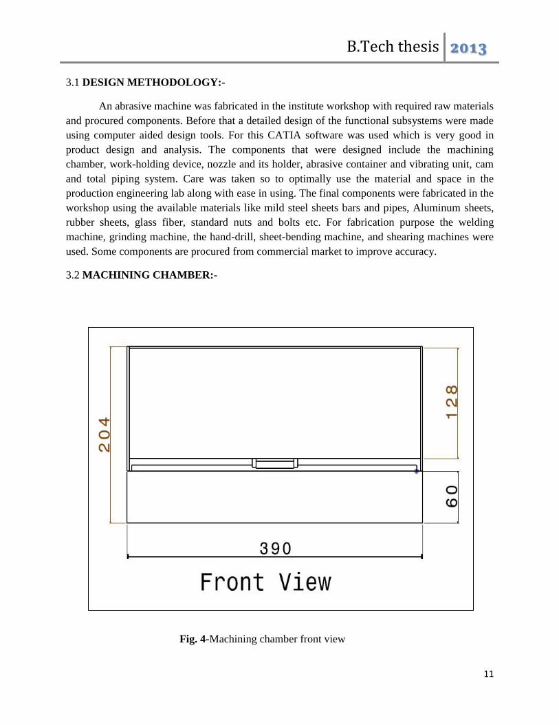
3.2 MACHINING CHAMBER:-
Fig. 4-Machining chamber front view
B.Tech thesis 2013
12
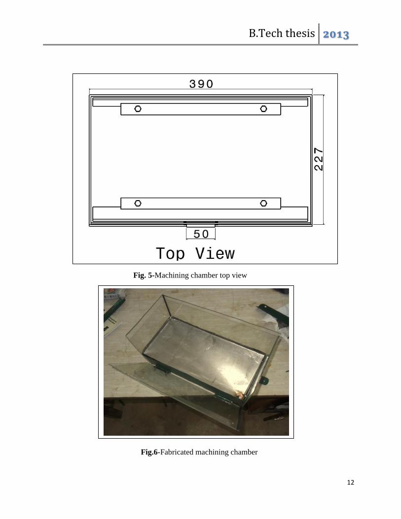
Fig. 5-Machining chamber top view
Fig.6-Fabricated machining chamber
B.Tech thesis 2013
13
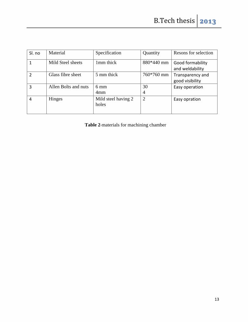
Sl. no Material Specification Quantity Resons for selection
1 Mild Steel sheets 1mm thick 880*440 mm Good formability and weldability
2 Glass fibre sheet 5 mm thick 760*760 mm Transparency and good visibility
3 Allen Bolts and nuts 6 mm
4mm
30
4 Easy operation
4 Hinges Mild steel having 2
holes
2
Easy opration
Table 2-materials for machining chamber
B.Tech thesis 2013
14
3.2.1 Air tight chamber:-
The abrasive particles used in AJM are of very fine grit size and can be remain suspended
in the air for very long time. Normally it is injurious to health if inhaled. So proper care has to be
taken to prevent it from mixing with the atmosphere and dispose it. For this purpose the chamber
was made air tight by application of suitable methodology.
At first mild steel sheet of 1 mm thickness was taken and was converted into a one side
open box with bending, shearing, cutting and welding operations. Mild steel sheet was chosen as
it has excellent formability along with weld ability Different holes were made at appropriate
places so as to accommodate the outer transparent glass fiber sheets. Transparent sheets were
chosen so as to increase the visibility of inside machining process.
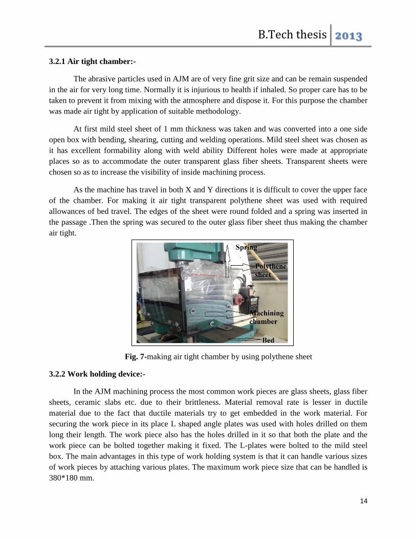
As the machine has travel in both X and Y directions it is difficult to cover the upper face
of the chamber. For making it air tight transparent polythene sheet was used with required
allowances of bed travel. The edges of the sheet were round folded and a spring was inserted in
the passage .Then the spring was secured to the outer glass fiber sheet thus making the chamber
air tight.
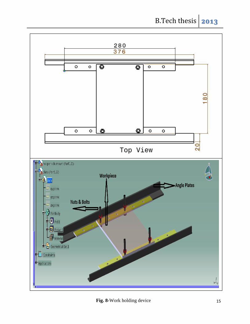
3.2.2 Work holding device:-
In the AJM machining process the most common work pieces are glass sheets, glass fiber
sheets, ceramic slabs etc. due to their brittleness. Material removal rate is lesser in ductile
material due to the fact that ductile materials try to get embedded in the work material. For
securing the work piece in its place L shaped angle plates was used with holes drilled on them
long their length. The work piece also has the holes drilled in it so that both the plate and the
work piece can be bolted together making it fixed. The L-plates were bolted to the mild steel
box. The main advantages in this type of work holding system is that it can handle various sizes
of work pieces by attaching various plates. The maximum work piece size that can be handled is
380*180 mm.
Fig. 7-making air tight chamber by using polythene sheet
B.Tech thesis 2013
15
Fig. 8-Work holding device
B.Tech thesis 2013
16
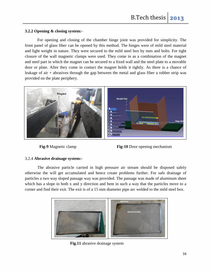
3.2.2 Opening & closing system:-
For opening and closing of the chamber hinge joint was provided for simplicity. The
front panel of glass fiber can be opened by this method. The hinges were of mild steel material
and light weight in nature. They were secured to the mild steel box by nuts and bolts. For tight
closure of the wall magnetic clamps were used. They come in as a combination of the magnet
and steel part in which the magnet can be secured to a fixed wall and the steel plate to a movable
door or plate. After they come in contact the magnet holds it tightly. As there is a chance of
leakage of air + abrasives through the gap between the metal and glass fiber a rubber strip was
provided on the plate periphery.
3.2.4 Abrasive drainage system:-
The abrasive particle carried in high pressure air stream should be disposed safely
otherwise the will get accumulated and hence create problems further. For safe drainage of
particles a two way sloped passage way was provided. The passage was made of aluminum sheet
which has a slope in both x and y direction and bent in such a way that the particles move to a
corner and find their exit. The exit is of a 15 mm diameter pipe arc welded to the mild steel box.
Fig-9 Magnetic clamp
Fig.11 abrasive drainage system
Fig-10 Door opening mechanism
B.Tech thesis 2013
17
3.3 Air & Abrasive delivery system:-
3.3.1 Air compressor:-
Air compressors compress the air to high pressure taking input energy from electric
motor or internal combustion engine. In abrasive jet machining high pressure air jet is required
so that the suspended particles in it can strike the work piece at high velocity. Positive-
displacement air compressors work by forcing air into a chamber whose volume is reduced to
compress the air. Piston type compressors use this principle by pumping air into an air chamber
through the use of the motion of pistons. They use one-way valves to direct air into a chamber,
where the air is compressed. Rotary screw compressors also use positive-displacement
compression by mating two helical screws that, when turned, send air into a chamber, whose
volume is reduced as the screws turn gradually. Vane compressors use a slotted rotor with varied
blade placement to lead air into a chamber compressing the volume. The applications of
compressors are to supply high-pressure air to fill gas cylinders, to supply moderate-pressure air
to a submerged surface supplied diver, to supply moderate-pressure air for driving some and
school building pneumatic HVAC control system valves, to supply a large amount of moderate-
pressure air to power pneumatic tools, to fill tires, to produce large volumes of moderate-
pressure air for large-scale industrial use such as oxidation for petroleum coking or cement plant
bag house purge systems. For this purpose a compressor with capacity 50 bar powered by
electric motor is used. The electric motor has the specification as follows. Power-3 HP, speed
1415 rpm, 3 phase induction motor.
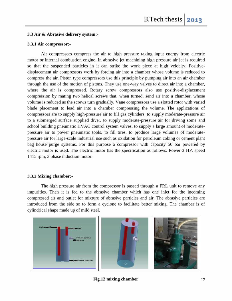
3.3.2 Mixing chamber:-
The high pressure air from the compressor is passed through a FRL unit to remove any
impurities. Then it is fed to the abrasive chamber which has one inlet for the incoming
compressed air and outlet for mixture of abrasive particles and air. The abrasive particles are
introduced from the side so to form a cyclone to facilitate better mixing. The chamber is of
cylindrical shape made up of mild steel.
Fig.12 mixing chamber
B.Tech thesis 2013
18
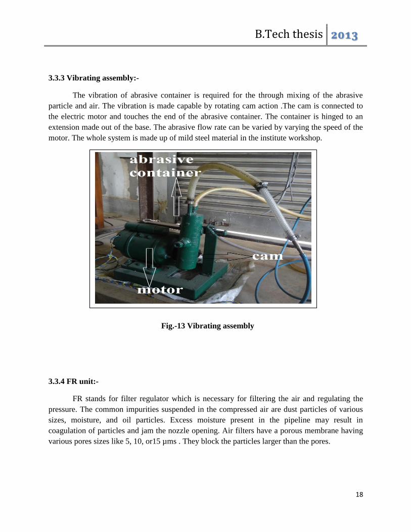
3.3.3 Vibrating assembly:-
The vibration of abrasive container is required for the through mixing of the abrasive
particle and air. The vibration is made capable by rotating cam action .The cam is connected to
the electric motor and touches the end of the abrasive container. The container is hinged to an
extension made out of the base. The abrasive flow rate can be varied by varying the speed of the
motor. The whole system is made up of mild steel material in the institute workshop.
3.3.4 FR unit:-
FR stands for filter regulator which is necessary for filtering the air and regulating the
pressure. The common impurities suspended in the compressed air are dust particles of various
sizes, moisture, and oil particles. Excess moisture present in the pipeline may result in
coagulation of particles and jam the nozzle opening. Air filters have a porous membrane having
various pores sizes like 5, 10, or15 µms . They block the particles larger than the pores.
Fig.-13 Vibrating assembly
B.Tech thesis 2013
19
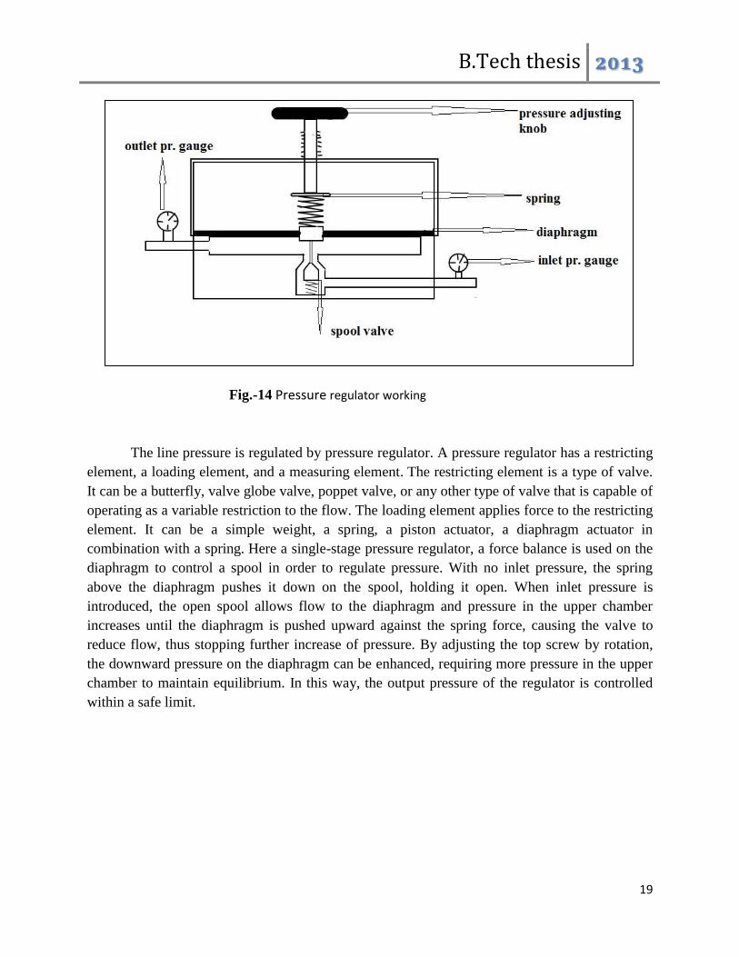
The line pressure is regulated by pressure regulator. A pressure regulator has a restricting
element, a loading element, and a measuring element. The restricting element is a type of valve.
It can be a butterfly, valve globe valve, poppet valve, or any other type of valve that is capable of
operating as a variable restriction to the flow. The loading element applies force to the restricting
element. It can be a simple weight, a spring, a piston actuator, a diaphragm actuator in
combination with a spring. Here a single-stage pressure regulator, a force balance is used on the
diaphragm to control a spool in order to regulate pressure. With no inlet pressure, the spring
above the diaphragm pushes it down on the spool, holding it open. When inlet pressure is
introduced, the open spool allows flow to the diaphragm and pressure in the upper chamber
increases until the diaphragm is pushed upward against the spring force, causing the valve to
reduce flow, thus stopping further increase of pressure. By adjusting the top screw by rotation,
the downward pressure on the diaphragm can be enhanced, requiring more pressure in the upper
chamber to maintain equilibrium. In this way, the output pressure of the regulator is controlled
within a safe limit.
Fig.-14 Pressure regulator working
B.Tech thesis 2013
20
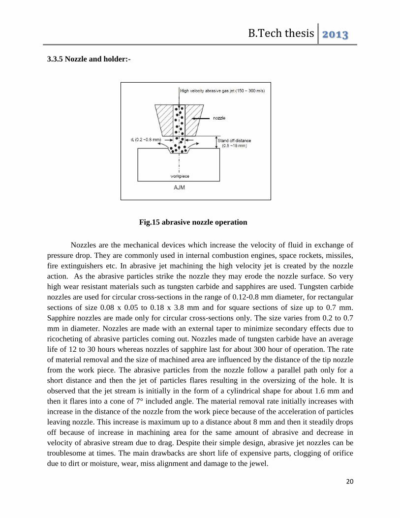
3.3.5 Nozzle and holder:-
Nozzles are the mechanical devices which increase the velocity of fluid in exchange of
pressure drop. They are commonly used in internal combustion engines, space rockets, missiles,
fire extinguishers etc. In abrasive jet machining the high velocity jet is created by the nozzle
action. As the abrasive particles strike the nozzle they may erode the nozzle surface. So very
high wear resistant materials such as tungsten carbide and sapphires are used. Tungsten carbide
nozzles are used for circular cross‐sections in the range of 0.12‐0.8 mm diameter, for rectangular
sections of size 0.08 x 0.05 to 0.18 x 3.8 mm and for square sections of size up to 0.7 mm.
Sapphire nozzles are made only for circular cross‐sections only. The size varies from 0.2 to 0.7
mm in diameter. Nozzles are made with an external taper to minimize secondary effects due to
ricocheting of abrasive particles coming out. Nozzles made of tungsten carbide have an average
life of 12 to 30 hours whereas nozzles of sapphire last for about 300 hour of operation. The rate
of material removal and the size of machined area are influenced by the distance of the tip nozzle
from the work piece. The abrasive particles from the nozzle follow a parallel path only for a
short distance and then the jet of particles flares resulting in the oversizing of the hole. It is
observed that the jet stream is initially in the form of a cylindrical shape for about 1.6 mm and
then it flares into a cone of 7° included angle. The material removal rate initially increases with
increase in the distance of the nozzle from the work piece because of the acceleration of particles
leaving nozzle. This increase is maximum up to a distance about 8 mm and then it steadily drops
off because of increase in machining area for the same amount of abrasive and decrease in
velocity of abrasive stream due to drag. Despite their simple design, abrasive jet nozzles can be
troublesome at times. The main drawbacks are short life of expensive parts, clogging of orifice
due to dirt or moisture, wear, miss alignment and damage to the jewel.
Fig.15 abrasive nozzle operation
B.Tech thesis 2013
21
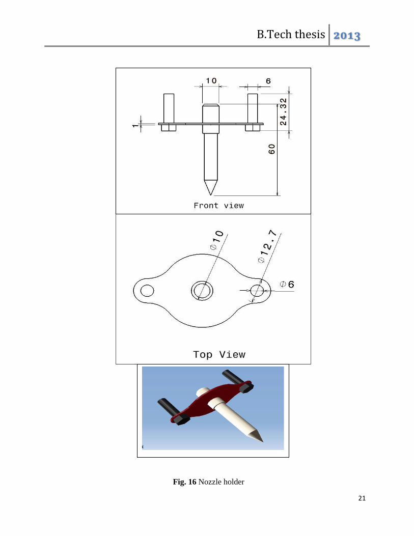
Fig. 16 Nozzle holder
B.Tech thesis 2013
22
Three nozzles having orifice diameters 0.6, 0.8 and 1 mm are used to facilitate the variation of
parameters. The nozzle material is tungsten carbide. They are procured from outside to increase
the efficiency and accuracy. The nozzle holder is made up of mild steel plate having a 10 mm
dia. hole to accommodate the nozzle. It is secured to the frame by two Allen bolts on both sides.
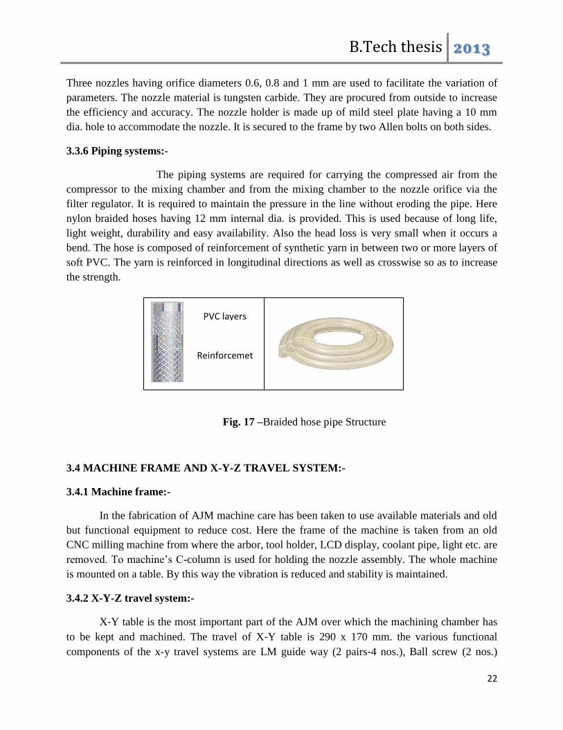
3.3.6 Piping systems:-
The piping systems are required for carrying the compressed air from the
compressor to the mixing chamber and from the mixing chamber to the nozzle orifice via the
filter regulator. It is required to maintain the pressure in the line without eroding the pipe. Here
nylon braided hoses having 12 mm internal dia. is provided. This is used because of long life,
light weight, durability and easy availability. Also the head loss is very small when it occurs a
bend. The hose is composed of reinforcement of synthetic yarn in between two or more layers of
soft PVC. The yarn is reinforced in longitudinal directions as well as crosswise so as to increase
the strength.
3.4 MACHINE FRAME AND X-Y-Z TRAVEL SYSTEM:-
3.4.1 Machine frame:-
In the fabrication of AJM machine care has been taken to use available materials and old
but functional equipment to reduce cost. Here the frame of the machine is taken from an old
CNC milling machine from where the arbor, tool holder, LCD display, coolant pipe, light etc. are
removed. To machine’s C-column is used for holding the nozzle assembly. The whole machine
is mounted on a table. By this way the vibration is reduced and stability is maintained.
3.4.2 X-Y-Z travel system:-
X‐Y table is the most important part of the AJM over which the machining chamber has
to be kept and machined. The travel of X‐Y table is 290 x 170 mm. the various functional
components of the x-y travel systems are LM guide way (2 pairs‐4 nos.), Ball screw (2 nos.)
PVC layers
Reinforcemet
nts
Fig. 17 –Braided hose pipe Structure
B.Tech thesis 2013
23
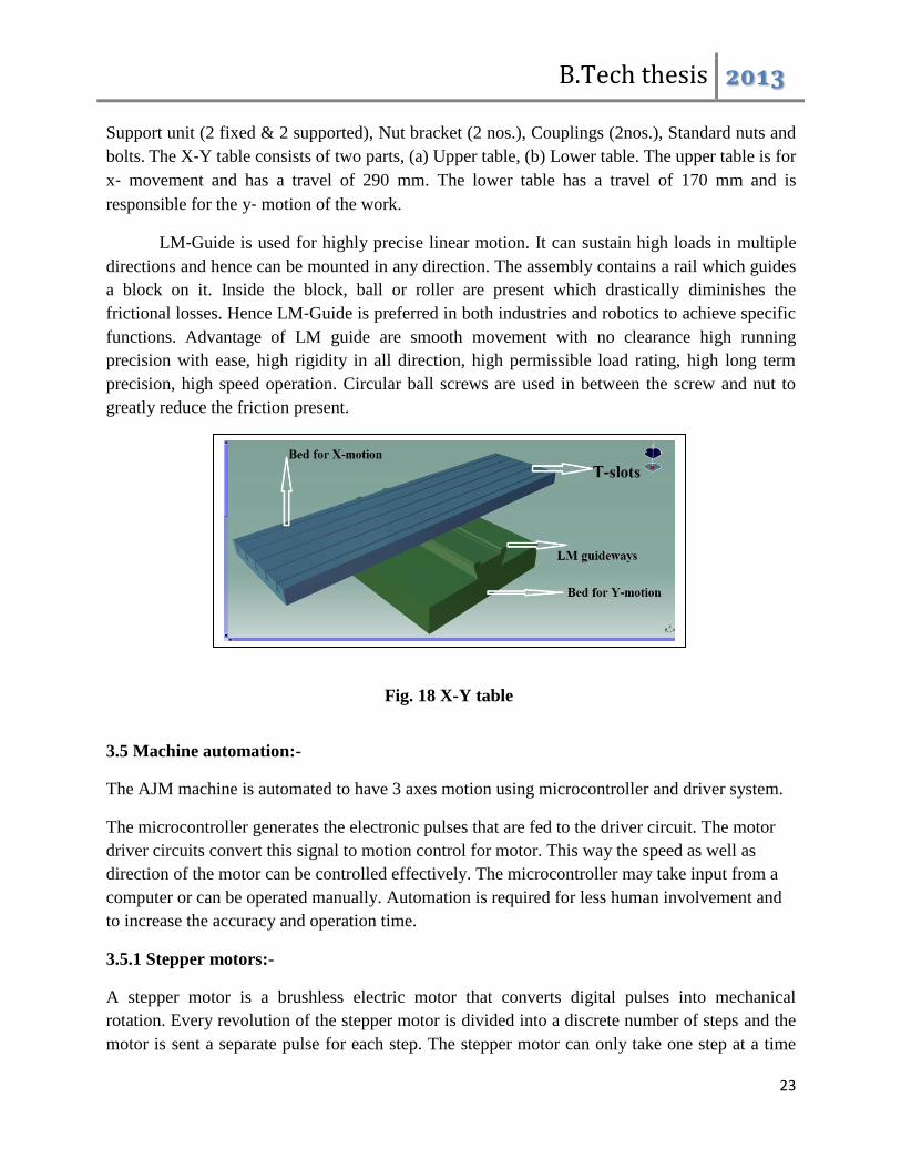
Support unit (2 fixed & 2 supported), Nut bracket (2 nos.), Couplings (2nos.), Standard nuts and
bolts. The X‐Y table consists of two parts, (a) Upper table, (b) Lower table. The upper table is for
x‐ movement and has a travel of 290 mm. The lower table has a travel of 170 mm and is
responsible for the y‐ motion of the work.
LM‐Guide is used for highly precise linear motion. It can sustain high loads in multiple
directions and hence can be mounted in any direction. The assembly contains a rail which guides
a block on it. Inside the block, ball or roller are present which drastically diminishes the
frictional losses. Hence LM‐Guide is preferred in both industries and robotics to achieve specific
functions. Advantage of LM guide are smooth movement with no clearance high running
precision with ease, high rigidity in all direction, high permissible load rating, high long term
precision, high speed operation. Circular ball screws are used in between the screw and nut to
greatly reduce the friction present.
3.5 Machine automation:-
The AJM machine is automated to have 3 axes motion using microcontroller and driver system.
The microcontroller generates the electronic pulses that are fed to the driver circuit. The motor
driver circuits convert this signal to motion control for motor. This way the speed as well as
direction of the motor can be controlled effectively. The microcontroller may take input from a
computer or can be operated manually. Automation is required for less human involvement and
to increase the accuracy and operation time.
3.5.1 Stepper motors:-
A stepper motor is a brushless electric motor that converts digital pulses into mechanical
rotation. Every revolution of the stepper motor is divided into a discrete number of steps and the
motor is sent a separate pulse for each step. The stepper motor can only take one step at a time
Fig. 18 X-Y table
B.Tech thesis 2013
24
and each step is of the equal size. As each pulse causes the motor to rotate a precise angle, the
motor's position can be controlled without any feedback mechanism. As the digital pulses
increase in frequency, the step movement changes into continuous rotation, with the speed of
rotation directly proportional to the frequency of the pulses. Stepper motors are in both industrial
and commercial applications because of their high torque at low speeds, low cost, high
reliability, and a simple, robust construction.
The main advantages are as follows:-
1. The rotation angle of the motor is proportional to the input pulse.
2. The motor has full starting torque (if the windings are energized).
3. Precise positioning and repeatability of movement since good stepper motors have an
accuracy of 3 to 5%.
4. Excellent response to starting/stopping/reversing.
5. Reliable in operation since there are no physical contacts brushes in the motor. Therefore
the life of the stepper motor is simply dependent on the life of the bearing.
6. The motors response to digital input pulses provides open-loop control, making the motor
simpler and less costly to control.
7. A wide range of rotational speeds are achieved as the speed is proportional to the
frequency of the input pulses.
There are three basic types of step motors variable reluctance, permanent magnet, and hybrid
type. Also based on the number of poles excited at a time it may be unipolar or bipolar stepper
motor. A stepper motor is used whenever controlled movement is required. There are two ways
to connect a stepper motor, in series or in parallel. A series connection provides a high
inductance and therefore greater torque at low speeds. A parallel connection will lower the
inductance which results in increased torque at faster speeds. The stepper motor driver receives
step and direction signals from control system and converts them into electrical signals to run the
step motor. One pulse is required for every step of the motor shaft. In full step mode, with a
standard 200-step motor, 200 step pulses are required to complete one revolution. The speed of
rotation is directly related to the pulse frequency. Some drivers have an on-board oscillator
which allows the use of an external analog signal or joystick or remote control to set the motor
speed.
The rotary motion of a stepper motor can be converted to linear motion using a lead screw/worm
gear drive. The lead, or pitch, of the lead screw is the linear distance traveled for one revolution
of the screw. Finer resolution is possible by using the step motor/drive system in micro stepping
mode. The main applications are printers, fax machines, high end office equipment, plotters, hard
disk-drives, medical equipment, automotive and many more. Stepper motor "step modes" include
Full, Half and Micro step.
B.Tech thesis 2013
25
In our machine three stepper motors are provided for three axes motion control. They are
mounted to the beds and the column. The rotary motion of the motors is converted to linear
motion by the lead screw arrangement. The specifications of motors are as follows”-
Sl no. parameter values
1 Steps 200 Steps/Rev,
2 Current 3.1 Amps
3 Voltage 2.9 V
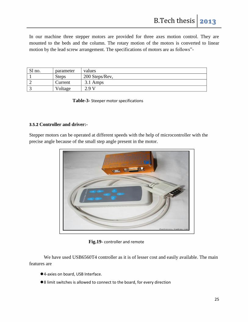
3.5.2 Controller and driver:-
Stepper motors can be operated at different speeds with the help of microcontroller with the
precise angle because of the small step angle present in the motor.
We have used USB6560T4 controller as it is of lesser cost and easily available. The main
features are
4-axies on board, USB Interface.
8 limit switches is allowed to connect to the board, for every direction
Table-3- Steeper motor specifications
Fig.19- controller and remote
control

B.Tech thesis 2013
26
Additional control box i.e. a remote control is present which can be used to control without a
computer.
B.Tech thesis 2013
27
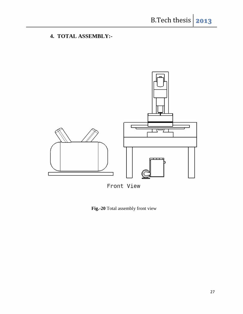
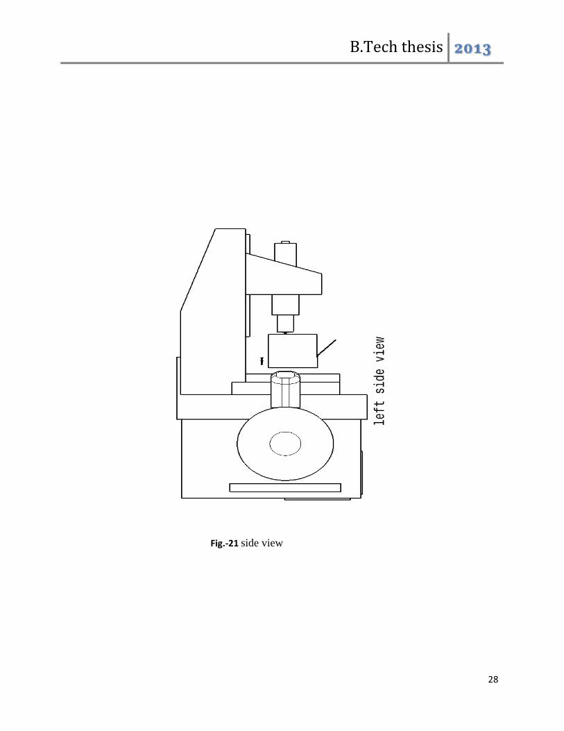
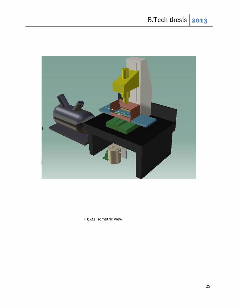
4. TOTAL ASSEMBLY:-
Fig.-20 Total assembly front view
B.Tech thesis 2013
28
Fig.-21 side view
B.Tech thesis 2013
29
Fig.-22 Isometric View
B.Tech thesis 2013
30
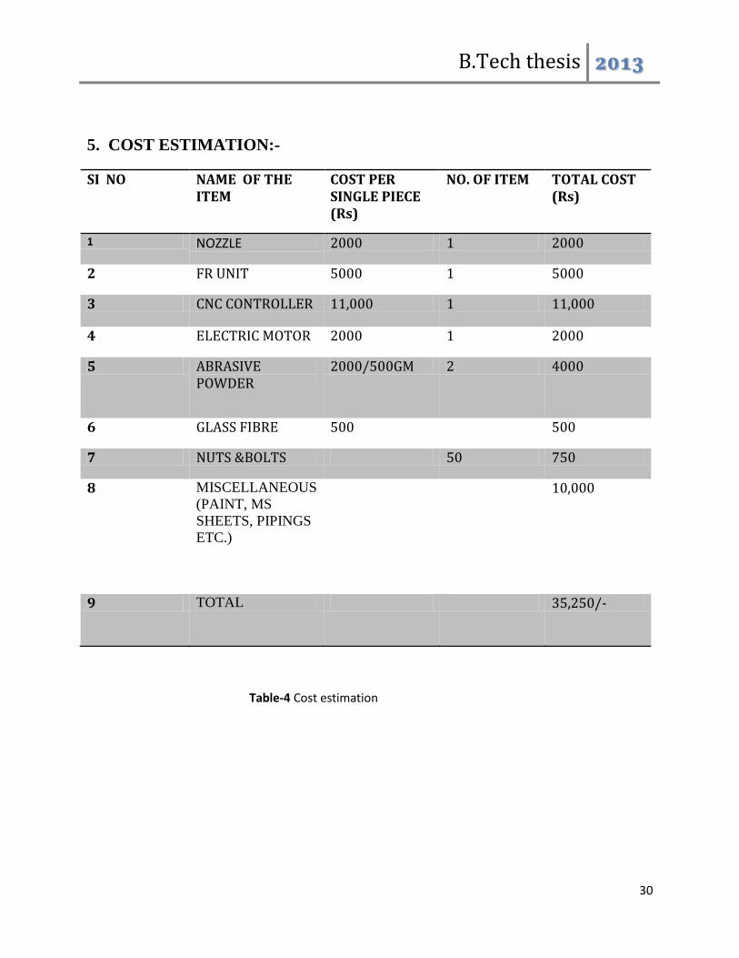
5. COST ESTIMATION:-
SI NO NAME OF THE ITEM
COST PER SINGLE PIECE (Rs)
NO. OF ITEM TOTAL COST (Rs)
1 NOZZLE 2000 1 2000
2 FR UNIT 5000 1 5000
3 CNC CONTROLLER 11,000 1 11,000
4 ELECTRIC MOTOR 2000 1 2000
5 ABRASIVE POWDER
2000/500GM 2 4000
6 GLASS FIBRE 500 500
7 NUTS &BOLTS 50 750
8 MISCELLANEOUS
(PAINT, MS
SHEETS, PIPINGS
ETC.)
10,000
9 TOTAL 35,250/-
Table-4 Cost estimation
B.Tech thesis 2013
31
4. CONCLUSION:-
In this project, a complete model of abrasive jet machine is fabricated in the institute production
engineering laboratory. Before fabrication a complete CAD model was prepared for optimum
use of material and space. Most of the components are made locally and sophisticated parts
which affect the accuracy greatly are procured from outside. The machine is automated using
micro-controller-driver-stepper motor combination. The machine can fabricate components
taking inputs from a computer or can be operated manually. This greatly reduces human effort
and improves accuracy.
B.Tech thesis 2013
32
5. REFERENCES:-
1. Residual stress and tribological characteristics of ground surface after abrasive jet restricted by grinding wheel
Authors: Liu, F., Gong, Y.‐D., Shan, Y.‐Q., Cai, G.‐Q.
Publication: Journal of Northeastern University, Volume 30, Issue 3, Pages 422‐425 March 2009.
2. Simulation and analysis of abrasive jet machining with wheel restriction in grinding
Authors: Wang, W.S., Zhu, L.D., Yu, T.B., Yang, J.Y., Tang, L. Publication: Key Engineering Materials, Volume 389‐390, Pages 387‐391, 2009
3. Abrasive waterjet turning—An efficient method to profile and dress grinding wheels Authors: D.A. Axinte, J.P. Stepanian, M.C. Kong, J. McGourlay
Publication: International Journal of Machine Tools and Manufacture, Volume 49, Issues 3‐4, March 2009, Pages 351‐356 Date: Dec, 2008
4. Modeling and simulation for material removal in abrasive jet precision finishing with wheel as restraint.
Authors: Li, C.H., Ding, Y.C., Lu, B.H.
Publication: Proceedings of the IEEE International Conference on Automation and Logistics, ICAL 2008, Article number 4636666, Pages 2869‐2873, 2008
5. Abrasive jet micro‐machining of planar areas and transitional slopes
Authors: Ghobeity, A.; Spelt, J. K.; Papini, M.
Publication: Journal of Micromechanics and Microengineering, Volume 18, Issue 5, pp. 055014., 2008
6. Three‐Dimensional CFD Simulation of Two phase Flow Inside the Abrasive Water Jet Cutting Head
Authors: Umberto Prisco; Maria Carmina D'Onofrio.
Publication: International Journal of Computational Methods in Engineering Science and Mechanics 9 (5), pp. 300‐319 , 2008
7. Machinability of glass by abrasive waterjet Authors: Zhu, H.T., Huang, C.Z., Wang, J., Lu, X.Y. and Feng, Y.X. Publication: International Journal of Materials and Product Technology, Vol. 31, No.1, pp.1
B.Tech thesis 2013
33
06–112, 2008. 8. Surface evolution models for abrasive jet micromachining of holes in glass and polymethylmeth
acrylate (PMMA)
Authors: Ghobeity, A.; Getu, H.; Papini, M.; Spelt, J. K. Publication: Journal of Micromechanics and Microengineering, Volume 17, Issue 11, pp. 2175‐2185 (2007). Date: 11/2007
9. Surface Roughness of Carbides Produced by Abrasive Water Jet Machining Authors: Khan, Ahsan Ali; Awang, Mohd Efendee Bin; Annuar, Ahmad Azwari Bin Publication: Journal of Applied Science, vol. 5, Issue 10, p.1757‐1761 Date: 06/2005
10. A Study on Abrasive Water Jet Machining of Aluminum with Garnet Abrasives. Authors: Khan, Ahsan Ali; Munajat, Noraziaty Bt.; Tajudin, Harnisah Bt. Publication: Journal of Applied Science, vol. 5, Issue 9, p.1650‐1654 Date: 01/2005
11. Effect of workpiece properties on machinability in abrasive jet machining of ceramic materials Authors: M. Wakuda, Y. Yamauchi and S. Kanzaki Publication: Precision Engineering, Volume 26, Issue 2, April 2002, Pages 193‐198
12. An experimental study on the abrasive jet deburring of cross‐drilled holes
Authors: R. Balasubramaniam, J. Krishnan and N. Ramakrishnan Publication: Journal of Materials Processing Technology, Volume 91, Issues 1‐3, 30 June 1999, Pages 178‐182
13. A study on the shape of the surface generated by abrasive jet machining
Authors: R. Balasubramaniam, J. Krishnan and N. Ramakrishnan Publication: Journal of Materials Processing Technology, Volume 121, Issue 1, 14 February 2002, Pages 102‐106
B.Tech thesis 2013
34
6. BIBLIOGRAPHY
1. “Production technology”, HMT publication.
2. “Elements of workshop technology”, S K Hajra Choudhury, S K Bose, A K Hajra choudhur
y, Niranjan Roy, Vol‐II, Media promoters and media publications
3. “Modern machining process”, S Pandey and H N Shah, S. Chand and co.
4. www.thefabricator.com
5. www.sciencedirect .com
6. www.wikipedia.org
7. www.elgi.com
8. www.nptel.iitm.ac.in
9. www.ebay.com
10. www.indiamart.com