Embed Size (px)
Citation preview

Fabrication Guidelines

02 Contents
Contents
Product description
Safety, Storage & Handling
Visual Consistency & Sawing
Saw Equipment
Routing & Folding
Additional Manufacturer Information
Corner Cutting & Bending
Joining Techniques
Coating / Printing / Cleaning Alupanel
Thermal Expansion
Compensation of Thermal Expansion
Wind Load Calculation
Appendix 1 - Accessories
Colour-matched screws & rivets
Gaskets
Appendix 2 - Machine manufacturer Information
ESKO, MECAPRO, TEKCEL, ZUND, AXYZ,
ALUBENDER, SBC Automation
3
4
5
6
7
8
9
10-12
13-14
15
16-17
18-21
Unit 6, Site 2, Oak Business Units,Thorverton Road, Matford, Exeter,Devon, EX2, 8FS Tel: +44 (0) 1392 823015
UK Manufacturing SiteUnit 2 Millyard WayEythorne, Dover,Kent, CT15 4NLTel: +44 (0) 1392 823015
Tel: +1 718 841 9940
www.multipaneluk.co.uk
Adhesive systems

Product Description 03
Product Description
UK Head Office Tel: +44 (0) 1392 823015 • USA Office Tel: +1 718 841 9940
www.multipaneluk.co.uk
Alupanel is a high-performance composite material consisting of two aluminium sheets bonded to an extruded thermoplastic core. As a result of this technology, we have created a perfectly flat and very formable material with an excellent strength-to-weight ratio.
Alupanel is supplied with a face PE paint finish, available in the widest colour range on the market.
The flexibility of the panel makes it a perfect material for sign makers, designers, architects, fabricators and installers.
Advantages include: - Exceptional rigidity- Outstanding strength to weight ratio- Simple to fabricate - Easy and quick to install- High resistance to atmospheric conditions- Easy to maintain
This manual has been developed to assist fabricators and installers to work with Alupanel in the most efficient manner possible. The following recommendations and product data are based on information which is, in our opinion, reliable.
However, since skill, judgment, and quality of equipment and tools are involved, and since conditions and methods of using Alupanel are beyond our control, the suggestions contained in this manual are provided without guarantee. We recommend that prospective users determine the suitability of both the material and recommendations before adopting them on a commercial scale.
In no event shall Multipanel UK Ltd, have any liability in any way related to or arising out of said suggestions and product data for direct, special, consequential or any other damages of any kind.
Protective Film
PE Paint Finish
Aluminium Skin
Adhesive Layer
Polyethylene Core

04 Safety, Storage and Handling
Safety, Storage and Handling
Safety:Standard health and safety precautions should be adhered to when fabricating Alupanel Material. Goggles or other face protection, as well as hearing protection and gloves should always be worn. An MSDS for Alupanel is available from your local sales representative or distributor.
Packaging:Alupanel comes as standard with a clear protective film, designed to be removed just before installation to offer protection from surface damage. Although the protective film is UV stabilised, it should be removed as soon as possible after installation, especially in the case of panels exposed to sunlight and adverse weather.
Handling:Alupanel should be handled with care, especially when dealing with long lengths. It is advisable that a small team carry out the handling. When removing panels from a pallet / stack never drag the panel, always lift clear above the remaining panels on the stack. This will require two or more operatives.
Storage:When storing unpacked Alupanel please observe the following guidelines :
• To prevent warping or bending, store horizontally.• Avoid stacking Alupanel of different sizes together, as the surface or panel can be damaged by the edges of the smaller pieces.• Preferably, store them by size
in racks.• If storing panels vertically by leaning them against a rack lay a rubber mat underneath and lean the Alupanel closely against the fixed back.• Alupanel is packed in wooden crates and can usually be stacked up to four crates high.• It is advisable to store Alupanel in a clean dry area with a minimum temperature of 15oC for a duration of 24 hours before use after which you will be able to start the processing requirements for each panel. After Alupanel has been removed from the stack it must be protected from any penetrating moisture.

Visual Consistency / Sawing 05
Visual Consistency & Sawing
UK Head Office Tel: +44 (0) 1392 823015 • USA Office Tel: +1 718 841 9940
www.multipaneluk.co.uk
Visual consistency:Each of our product types has special characteristics that can affect the visual consistency from batch to batch and even from panel to panel. It is important that these characteristics be considered when planning how to use and install Alupanel.
Solid colours: The industry standard for allowable variation for panel to panel and batch to batch is Delta E 1.0 or less in a hunter colour space. Brighter colours, such as reds, yellows, blues, etc, which tend to be less opaque and which depend somewhat on film build (paint thickness) to achieve their appearance, will be more likely to exhibit more variation than subdued colours.
Projects - same batch
Metallic colours: The industry standard for colour variation with metallic is Delta E 2.5 or less, much larger than the standard for solid colours.
Directional project:In coating, the flakes will tend to align in one direction. This greatly increases the directionality of the panel’s appearance.
Production Batches/Projects: When working on projects it is
highly recommended that material from the same production batch is used in order to maintain overall visual consistency.
For these reasons the panels must be installed with the directional arrows all aligned in the same direction. Batches should not be mixed on a building face without first contacting Multipanel UK Ltd for a confirmation that they are visually similar enough to be used together.
Before fabrication, remember to use a felt tip pen to draw arrows to indicate the coating direction on any small pieces that might be cut out from areas without the directional arrows.
Sawing:Sawing Alupanel is an easy process that can be done with ordinary commercial metal and woodworking equipment. Saw blades and router bits are available through independent distributors who handle cutting tools. Prior to processing large quantities, trial saw cuttings should be done to evaluate both the tool working conditions and the recommended cutting speeds. For marking the panels the use of a soft pencil is adequate. Hard marking tools should be avoided as they can fracture the Aluminium surface.
It is recommended that the swarf formed during cutting should be vacuumed away with compressed air.
Due to the nature of the Alupanel it is best to move the saw blade rather than the material as no scratch will remain on the panel. If good saw cutting practices are applied and recommendations followed, the result should be clean cuts with little bur. If despite following the recommendations, ragged cuts are produced check the following causes; poor tool support, tool vibration, blunt cutting edges, high frictional heat at the cutting edge.
As Alupanel has low thermal conductivity it cannot be cooled easily with compressed air or any other means. Therefore it is recommended to select the tool geometry and cutting conditions in such a manner so as to minimize the frictional forces developed at the cutting point and keep the resulting heat at a low level.

06 Saw equipment
Saw equipment
Panel Saws: Panel saws provide an effective method of cutting. These saws, whether standard equipment or custom made, perform well and have the added advantage of space saving. If a panel saw is to be used as production equipment, an industrial model should be purchased in order to obtain adequate cutting tolerances and increase the longevity of the equipment.
Table Saws:Table saws are not recommended for large sheets.
Multiple Operation Rip/V-Grooving Saws: In high production operations, equipment that is capable of performing more than one operation with a single pass through the machinery is recommended. This equipment can make multiple saw cuts (sizing the panel) and V-Grooves (rout) at the same time.
Portable Circular Saws:Cutting Alupanel with portable circular saws is another effective method. As mentioned, this equipment should also be production/industrial standard equipment.
Jig Saws: Jig saws work well for cut-outs. Care should be taken with portable jig saws to prevent damage to the Alupanel material surface. More than one sheet can be cut at a time by stacking panels.
If centre cutting (i.e., letter cut-outs) is required, a foam pad may be placed under the material with the blade cutting into the foam. The sheets may be clamped or secured with double-sided tape for the cutting operation. When clamping between jaws, protect the panel surface against damage.
Working Method Cutting Material
Blade/Band Geometry
Tooth Geometry
Max. Cutting Speed
Max. Cutting Feed
Circular Saws Carbide tipped orhighspeed steel
20 x 35mm blades with maximum number of carbide teeth available, designed for cutting non-ferrous material. The blade should be ground thinner from the rim towards the centre to prevent pinching.
Angle or circular tooth, alternate bevelled, tripleground. Tooth gap wall rounded. Chip angle: 5°to15°.Clearance angle:10°to 30°. Tooth spacing: 4mm to 25 mm, fine spacing preferable.
5500 RPM 40 mm/sec
Band Saws Tempered springstrip steel.
Thickness: 0.8 mm to 1.2 mm. Width: 15 mm to 25 mm. Use racket or straight set.
Skip teeth, designed for nonferrous and ferrous materials (light metals and plastics). Tooth spacing: minimum 4 teeth per cm.
10000 RPM 25mm/sec
Reciprocatingsaws
High speed steel. Thickness: 0.8 mm to 1.2 mm. Width: 5 mm to15 mm).
Hook or circular tooth with alternate angles, set or waved. Tooth spacing: 2 mm to 6 mm
10 mm/sec
Saw cutting can be accomplished with the following equipment:

Routing & Folding 07
Routing & Folding Introduction
UK Head Office Tel: +44 (0) 1392 823015 • USA Office Tel: +1 718 841 9940
www.multipaneluk.co.uk
of the routings with the help of the chosen guided system.
Hand operated router:These tools consist of routers that are commonly available on the market and are used for wood processing. If they are equipped with special routing bits (carbide tipped cutter) the hand operated router can be used for a limited number of processes. In this case the stability of the tool and the guide-system considerably affect the quality of the routing.
Work directions:For shaped elements with a radius of between 2-7mm proceed as follows:
• The shape of the groove and its respective depth determines the folding radius. Note that smooth bending (shape forming of elements) cannot be obtained without uniform thickness of polyethylene remaining.
Alupanel can be routed using conventional Routing machines. For accurate and precise manual folding of the Alupanel composite panels, resulting in a good finish, we recommend to route the rear of the panels to 2.5mm thick, going through the exterior aluminium layer, and some of the Polyethylene core. Normally the panel is grooved and folded 25-70mm from the edge.
In order to route Alupanel the following equipment is necessary:
Vertical panel saw: Equipped with specially shaped routing saw blades. The equipment needed is the same vertical saw as the one used for the cutting, but with a different saw blade and relevant equipment for adjusting the routing thickness.
The use of a chip collectoris essential.
Portable circular saw: A portable circular saw equipped with a suitable routing disk can be used, but only for a limited amount of processes. Note that special care should be given to the stability of the portable circular saw during processing of the material, as well as the precision

08 Routing & Folding
Routing & Folding Methods
Carbide Saw:By routing on just one of the sides of Alupanel, it can be bent upwards or downwards to create both an inside or outside corner.
When a groove is bent at a 90° angle the bending radius of the final product will be 3-3.5mm and the element will elongate by 0.5-1.0mm. As such, the original panels should be cut shorter by that proportion.
Grooving equipment:For processing a small number of panels a router and trimmer can be used.
For processing large volumes a table saw/CNC router and a grooving cutter are needed along with a lifter.
Technical characteristics of carbide saw-tip:
Outside diameter: 305No of the teeth: 24RPM: 3000 to 5000

UK Head Office Tel: +44 (0) 1392 823015 • USA Office Tel: +1 718 841 9940
Corner Cutting & Bending 09
Corner Cutting &Bending
Wood chisel: A sharp hammer blow to a wood chisel allows you to cut out the small thickness at the bottom of a routing groove with no difficulty. The wood chisel must be wider than the part to be cut out. With a little experience, good clean joints can be easily achieved.
Punching:This technique is the most productive, with the corners being cut out and the corner fastening holes being put in a single operation.
The minimum bending radius for Alupanel without routing the back skin is forty times the thickness of the panel being curved i.e., 4 mm = 160 mm minimum radius.
Alupanel can be cold formed in a pyramid roller, a press brake or over a clamped pipe. The process is similar to the forming of aluminium; however, due to the sensitive surface, care should be taken to ensure rollers are clean, smooth and free of defects to avoid damage to the surface.
Pyramid Roller:As an extra precaution, a protective film should be used between the panel and the rollers to further shield the panel surface. Do not pinch the Alupanel between the rollers. Roll the panel 3° to 5° tighter to allow for a small amount of spring back that will
occur. Once the sheet is curved; however, it will remain curved.
Press Brake:When forming with a press brake, use a top die (tubular) with the radius desired and open the bottom die (jaws) approximately two times the thickness of the material plus film wider than the top die. The lower die should always have a protective pad of not less than 3mm film.
Some adjustment of the lower jaws may be necessary to allow for varying bending properties between anodized and painted finish and for varying thicknesses. The radius of the top die will be the approximate inside radius of the finished panel.
Bending Over a Clamped Pipe:Alupanel may be formed over a
pipe of the proper diameter that is securely clamped to a work table. A hinged “leaf” attached to the end of the table will bend the material easily.
Pyramid Roller
Press Brake
Two methods are normally used for cutting out corners to allow the forming of a cassette.

10 Drilling / Joining
Joining Techniques One
Please find below some important general information about joining techniques. Use the following guidelines when other elements come in direct contact with the surface of Alupanel Material:
Acceptable joining materials: aluminium, plastic, stainless steel, plated or coated steel with cadmium, zinc or aluminum.
Unacceptable joining materials: copper, brass, bronze, iron, raw steel. Unacceptable materials cause corrosion of joining surfaces due to electrolysis of dissimilar materials. Therefore, use “heavy” or “red” metals only with an electrically insulating intermediate layer.
When joining elements are to be anodized, assemble the materials after the anodizing process. Proper consideration should be given to the thermal expansion characteristics of Alupanel Material when using any of the joining techniques.
Pop rivets are often used to attach aluminium clip angles and other structural or ornamental elements to Alupanel. Because the rivet body will be in contact with the aluminium skin of the panel, it
is recommended that either aluminium or stainless steel rivets be used to avoid dissimilar metals contacting. Ultimate shear and tensile strengths of various rivets are available from the rivet manufacturer.
Please be advised that some building code jurisdictions do not endorse the use of pop rivets for structural connections.
Drilling:Alupanel can be drilled with standard drills used for aluminium and plastics.
Working Specifications:
Drill bit: Twist drill, high speed steel.
Tip Angle:100-140 degrees, or counter-bore grind with centering tip.
Cutting speed:164 RPM to 984 RPM.
Quick removal of chips can be achieved by a high RPM, slow feed speed and occasional lifting of the bit.
Joining:A variety of different fasteners are used to fabricate and install Alupanel. Structural adequacy and selection of these fasteners are the responsibility of qualified engineers and in most instances where architectural panels are used, certified calculations will be required by the Building Official. You may successfully use specific fasteners for panel load testing purposes in obtaining building code recognition.

Through bolts:These provide an excellent way to join sheets of Alupanel together, or to other elements. Galvanized, stainless steel or aluminium bolts, nuts and washers should be used to avoid dissimilar metal contact.
Caution is recommended in tightening the nut onto the bolt. Because the plastic core material is compressible, over tightening can deform the metal skins. Use lock nuts or double nuts with washers to prevent the nut from loosening over time.
Testing is advisable to determine the performance of any fastening system.
UK Head Office Tel: +44 (0) 1392 823015 • USA Office Tel: +1 718 841 9940
www.multipaneluk.co.uk
Screwing / Bolting 11
Joining Techniques Two
Screws:Screws are also used to perform many of the same applications as rivets. Stainless steel screws are industry standard and are appropriate to avoid corrosion and dissimilar metal contact. Because screws are customarily installed through pre-drilled holes it is recommended that sheet metal screw thread type fasteners be used, especially when the screw is under tension load and this load is resisted by the aluminium skins.
Occasionally, Alupanel is face fastened directly to supports or sub-grids. The type and thickness of the support metal, as well as the applied load, will dictate the size and thread type of the correct fastener.

12 Welding / Adhesive Bonding
Joining Techniques Three
Welding:This method is frequently used to assemble Alupanel. The filler rod and the polyethylene core are welded together after heating by a jet of hot air projected by an electrically heated welding gun.
For good quality welding, you need : - Good preparation of the edges to be welded together - Adequate filler rod quality - A good welding speed - Evenly applied pressure - Clean hot air - An appropriate temperature
Welding by the to-and-fro method:Hold the filler rod at a right angle whilst exerting regular pressure on the rod, make to-and-fro B-B (non-circular) movements. The filler rod and the edges to be welded must be heated in a similar way.
Welding using a high-speed nozzle:Normal hot air guns fitted with a removable high-speed welding nozzle allow the edges to be welded and the filler rod to be heated at the same time. This makes for better quality welding. The filler rod is pushed by the constant pressure of the high-speed nozzle, and is therefore pressed between the edges to be welded.
Preparation of the edges to be welded:
Butt welding: The edges must be bevelled.
Corner assembly:Only one of the panels is bevelled.
T-assembly:Remove the narrow strip of metal skin to free the areas to be welded.
Welding of a fold:Bevel the edges to be welded first of all using a shaped milling cutter.
The polyethylene core oxidizes relatively quickly once exposed to the air. It must be welded within 24 hours max after it is bevelled. Once it has cooled, it is possible to remove the welding flash using a knife or scraper. We recommend that this operation be carried out in a clean, oil and water-free area.
The specific welding qualities of the filler rod are:Polyethylene: low density Colour: unpigmentedDensity: 0.9 g/cm3Diameter of rod: 3, 4 and 5mm
Immediately before welding,remove the outer layer of oxide from the filler rod.
Adhesive Bonding:In addition to structural adhesives, double sided tape can be used for fixing Alupanel on flat surfaces such as walls, ceilings, furniture, coverings etc.
Extreme care should be given when selecting the adhesive so as to ensure it is chosen according to the application and the environmental conditions.
It is important that the manufacturer is consulted for further instructions prior to the usage of the adhesive.
The substrate surface should be clean before the application of the structural adhesive.

UK Head Office Tel: +44 (0) 1392 823015 • USA Office Tel: +1 718 841 9940
www.multipaneluk.co.uk
Printing / Cleaning 13
Coating / Printing / Cleaning Alupanel - ‘Easy Peel’One
Easy Peel Protective Filmensures no residue is left onthe panel, reducing cleaningtime and eliminating the riskof interference with the print.An ultra white surface helpsto display printed colourswith increased brightness andintensity, with a special coatingalso delivering vastly improvedink adhesion for colour fastprints. Developed for the printmarket, Alupanel Ultrawhite issuitable for use both indoorsand out and, is available with thereverse side milled and coveredwith transparent digital lacquerproviding perfect adhesion forprints, achieving an amazinglook of aluminium surface withcolourful prints.
Off-line Coating:Alupanel can be coated off-line if necessary. It is advisable to follow instructions as specified by the manufacturer of any paints to be used.
For off-line coating observe the fol-lowing guidelines: - Surface should be lightly abraded to provide a better coating surface. The Surface should then be cleaned of all contaminates i.e. dust, dirt and oil etc. A soft cloth with a non- petroleum based solvent (e.g. rubbing alcohol) should be used to clean the surface area. - Curing should be done at room temperature since temperatures above 1750F can cause Alupanel to deform.
Screen Printing:Alupanel is perfect for printing with an epoxy base or urethane base two-part type ink/paint. When selecting an ink, confirm its weather ability and adhesion with the ink manufacturer. It is recommended to test the ink adhesion on the surface of Alupanel before printing.
For printing on Alupanel, observe the following guidelines: - Remove all dust and dirt on the surface of Alupanel. Oily dirt causes splintering, splitting, or other defects of the paint. It must be completely removed with a soft cloth dipped in alcohol, N-hexane, etc. If storage or drying is not done correctly, the adhesion or other performance may be adversely affected. Therefore, observe the storing conditions of each paint as specified by the manufacturer. - Since storing in high temperature may cause deformation, ensure the storing temperature is kept below 175oF and store horizontally.

Cleaning:Alupanel should be regularly cleaned following the method below. The surface of the panel will commonly accumulate dust, dirt and other airborne particles. In the case of panels used externally, various hydrocarbons from airborne exhausts are also likely to need removal. It is also possible that surfaces could be contaminated with synthetic hydrocarbons from other exhausts such as synthetic grease, oil, hydraulic fluids, lubricants or stains from vegetation or animal matter.
Cleaning Method: We recommend a 4-step cleaning method:1. Flush Alupanel with water from a hose.2. Wipe lightly with a soft cloth.3. Use pressure washer.4. Use detergent in a power wash or with a soft cloth for hand wiping and flush with water.
Coating / Printing / Cleaning Alupanel - ‘Easy Peel’Two
Alupanel & Alupanel UWD- pHtest/print life-spanTests have been undertakento determine the acidity of ourAlupanel and Alupanel Ultra WhiteDigital panels. An Insta-checkpH pencil (by Micro EssentialLaboratory) was used to carry outthe tests.
The panel surface was moistenedwith distilled water and left for 3minutes. Several lines were drawnwith the Insta-Check pH pencil onthe wet surface. After 15 secondsthe color of the lines was compared with a pH color chart. The colours of the lines matched the colour on the chart corresponding to a pHlevel of 7, which indicates that thesubstance is neutral. In conclusion, we can state that the surface of our digital panels is not acidic and that coatings/paints applied will last for years. This means that Alupanel issuitable, for example, for archivalapplications.
Material Compatibility:Alupanel is an extremely durable material that has been designed to withstand significant exposure to environmental conditions. It is unlikely to be compromised by any cleaning process that would conceivably be used on the material.
14 Printing / Cleaning
However, in the interests of maintaining the finish of the material, the prudent user will select products with a pH of 10 or less and which do not contain bleaches, ammonia or caustic ingredients such as sodium hydroxide, potassium hydroxide or sodium metasillicate. It is also recommended that users avoid abrasive materials or tools such as scouring powders, fibre pads or brushes.
Easy Peel Protective Film
9 No residue
9 Reduce cleaning time
9 Elimination of print interference
9 Ultra white surface
9 Bright and intense colours
9 Vastly improve ink adhesion
9 Suitable for indoors and out
9 Available with reverse side milled
9 Digital lacquer covering option

UK Head Office Tel: +44 (0) 1392 823015 • USA Office Tel: +1 718 841 9940
www.multipaneluk.co.uk
All the materials used inconstruction and sign makingwill expand when exposed tohigh temperatures and shrinkwhen the temperature falls.Each material has its ownthermal expansion rate. In themetric system it is measuredin mm/m/100DC and showshow many milimiters one meterof material will expand whenthe temperature changes 100degrees Celcius.
For example, for steel andconcrete this rate is around1,2mm and for PVC it is 5,2mm.When dierent materials are fi xedtogether it is always neccessary totake into account their expansionrates and exposure of thosematerials to dierent temperatures.
Sometimes it may happenthat a substrate on which Alupanelis designed to be installed isrigidly fi xed without taking thermalexpansion into consideration.In this case this substratecan bow and deform causingsubsequent bowing of theAlupanel fi xed to this substrate. To prevent this substrates on which Alupanel is going to be installed shall be carefully examined.
Alupanel consists of 2 aluminiumlayers bonded to a polyethylenecore. Thermal expansion ofAlupanel is determined by theproperties of its aluminium skins.Thermal deflection of aluminiumis 2,4 mm/m/100oC. So a2440mm long panel with a100oCtemperature fluctuation willexpand 5,86mm and its lengthwill become 2445,86mm undernew temperature conditions.
At the same time, if 2 edges ofthe panel are fixed, the tension in Aluminium skins will lead to panel bowing. Bowing deflection in this case will be 73,2mm. It is very important to make sure that when installation is carried out in the conditions where essential temperature fluctuationsare expected, fixings shall bedesigned to allow free thermalexpansion of the panels.
Thermal Expansion
Thermal Expansion 15
Alupanel after 100 degrees temperature increase. Length - 2445,86mm
73,2
2440
Alupanel at initial temperature. Length - 2440mm
Alupanel
Alupanel
Substrate
Substrate

Compensation ofThermal ExpansionOne
When installed outdoors underdirect sunlight Alupanel surfacetemperature can achieve up to75°C for dark colours. Minimumwinter value in Northern countriesshall be taken as -35°C. Beforeany installation it is very importantto calculate possible thermalmovements and choose theright solution to compensate taking into account materialsof the subframe, temperatureduring installation, minimum and
maximum temperatures ininstallation area. Compensationof thermal expansion meansthat Alupanel fixing shall bedone to allow some freedom infixing points so that the panelcan independently slide alongthe subframe when shrinking orexpansion of the panel differs fromthat of the subframe. It allows forthe prevention of tension whichcan lead to panel bending ordamage to the fixings.
Channel systems and clippingsystems allow free movement ofthe panel alongside the profile.A fixing a gap should alwaysbe left between panel edge andchannel end to allow the panel toexpand perpendicullary tothe profile.
Problems with thermal movementsoften happen when a panel is fixedto the subframe with rivets or screws. To prevent this, special tools shall be used during such installation.
When Alupanel is fixed by rivets, an adjusted step drill and riveting gun with special nozzle shall be used. A step drill cuts a d5,2mm hole in the subframe profile while an 8,5mm or bigger hole is cut in the panel.A special nozzle for riveting gunsis used to prevent jamming of therivet head into the panel surface.It fixes the rivet so that a small gapis left between the panel surface and the rivet head to allow free panel movement. Rivets with bigger heads shall also be used. Normaly, rivets with 14 or 16mm heads are used.
When screws are used to fixAlupanel it is possible to use a step drill with the first drill radius at least 1mm smaller than the shaft of the screw. Another option will be to cut holes for the screws in Alupanel prior to installation. The radius of such holes shall be calculated depending on a project to allow free panel movement. Normally at least 8,5mm holes shall be made for 5mm screws. Screws shall becarefully centerd in the holes during installation. Screws shall not be fixed tightly and should not jam into the Alupanel.
It is recommended to turn thescrew 180° to make sure it is nottight. Screws with countersunkheads should not be used.
16 Alupanel Installation Tips
5,20

Compensation ofThermal ExpansionTwo
Sometimes panel length is toobig and holes with a biggerdiameter can not compensatethermal movement. In such casesoval holes can be cut into thepanel. At the same time one ortwo round holes should be cut tokeep the panel in place. A specialcutting drill bit can be used tocut such holes.When a panel is fixed to more than two profiles it is recommended to make the centre of the panel tightly fixed while the sides of the panel shall be left loose.
Glue SystemsFor projects where essentialthermal movements are expectedonly special flexible glues shallbe used. Normally it can bepolyurethane based glues withflexibility at brake of 300% ormore. It is very important toconsult a representative of theglue maker to make sure theglue is suitable for the specifcproject. During installation gluemaker’s instructions shallbe strictly followed.
As a general rule glue thicknessshall be 3mm at least to havea flexible joint. This can beachieved by using doublesidedadhesive tapes or other spacerswith the neccessary height. It isrecommended to apply the gluewith a special nozzle formingtriangle glue beads. Height ofsuch a bead shall be at leasttwo times height of the spacer
Alupanel Installation Tips 17
to expansion
to expansion
Spacer GlueH
2H
UK Head Office Tel: +44 (0) 1392 823015 • USA Office Tel: +1 718 841 9940

18 Wind Load Calculation
Wind Load CalculationOne
Alupanel strength calculations:The composite technology of Alupanel makes the material very light and extremely rigid. For these reasons, Alupanel is used across the world in many different sign and architectural projects including those at substantial height subjected to high wind load and wind suction conditions.
The following guide has been designed to enable easycalculations for any Alupanelproject subject to windy conditions.
Alupanel presents a “truss” where characteristics of the panel are determined by characteristics of its upper and bottom aluminium layers. Our Aluminium layers are made of aluminium alloy AA1100H18 with tensile yield strength of 22000psi. It is the maximum tension material can bear before deformations turn to be irreversible.
Alupanel is available in different thicknesses so, please refer tothe below formula and table to calculate apparent thickness of your exact Alupanel type.
The next considerations are loading and support conditions. Support conditions are determined by the installation methods used. Wind pressure and suction loads are determined by height on which panels are going to be installed and situation of the building. Local building and wind codes should bereferred for this information. Depending on support conditions different calculation methods should be used. Please choose your support conditions from the table below and use appropriate formula from the next column to calculate exact figure of the stress.
W - unit area load, psf
T= Tpanel 3 - Tc ore3
Tpanel
Product Panel Thickness (mm)
Aluminium Layer Thickness (mm)
Apparent Thickness
Alupanel 2 2 0.3 0,0638
Alupanel 3 3 0.3 0,0827
Alupanel 4 4 0.3 0,0976
Alupanel 4 4 0.5 0,1197
Alupanel 6 6 0.5 0,1531
Please see table for apparent thicknesses for Alupanel types:
Alupanel is available in different thicknesses so please refer to the formula and table below to cal-culate apparent thickness of your exact Alupanel type.
T -apparent thickness of Alupanel
Tpanel -total thickness of Alupanel
Tcore -thickness of core material

UK Head Office Tel: +44 (0) 1392 823015 • USA Office Tel: +1 718 841 9940
Wind Load Calculation 19
Wind Load CalculationTwo
1. 1 side fixed, 3 sides free; evenly distributed load.
2. 2 sides simply supported, 2 sides free; evenly distributed load.
3. 1 side fixed opposite side simply supported, 2 sides free; evenly distributed load.
4. 2 sides fixed, 2 sides free; evenly distributed load.
5. 4 sides simply supported; evenly distributed load.
l/hß
10.2874
1. 20.3762
1. 40.4530
1. 60.5172
1. 80.5688
2. 00.6102
3. 00.7134
3wl2
T2
wl2
T234
x
wl2
T234
x
wl2
T212
x
wl2
T2x
l
h
l
h
l
h
l
h
l
h

20 Wind Load Calculation
6. 4 sides fixed; evenly distributed load.
7. Longer sides fixed, shorter sides simply supported; evenly distributed load.
8. Longer sides simply supported, shorter sides fixed; evenly distributed load.
9. 1 longer side fixed, another longer side free, shorter sides simply supported; evenly dis tributed load.
10. 1 shorter side free, other sides simply supported; evenly distributed load.
l/hß
10.3087
1. 20.3834
1. 40.4356
1. 60.4680
1. 80.4872
2. 00.4974
l/hß
10.4182
1. 20.4086
1. 40.4860
1. 60.4968
1. 80.4971
2. 00.4973
wl2
T2x
wl2
T2x
l/hß
10.4182
1. 20.5208
1. 40.5988
1. 60.6540
1. 80.6912
2. 00.7146
l/hß
10.714
1. 51.362
21.914
32.568
l/hß
10.67
1. 50.77
20.79
40. 8
wl2
T2x
wl2
T2x
wl2
T2x
l
h
l
h
l
h
l
h
l
h
Wind Load CalculationThree

UK Head Office Tel: +44 (0) 1392 823015 • USA Office Tel: +1 718 841 9940
www.multipaneluk.co.uk
Wind Load Calculation 21
11. 2 sides simply supported, 2 sides free, centre load
12. 2 sides fixed, 2 sides free, centre load
13. 1 side fixed, other sides free, tip load
14. 4 sides simply supported, concentrated centre load
15. 4 sides fixed, concentrated centre load
whIT 2
34
x
whIT 2
34
x
x whIT 2
x wT2
l
h
l
h
l
h
l
h
l
h
x(4.3 log +1-3.3ß)wT2
Wind Load CalculationFour

Fabrication Guidelines
APPENDIX 1 - Accessories

ALUFIXXT
Accessories for ALUPANELXT
Tel: +44 (0) 1782 629 270
Fax: +44 (0) 1782 619 362
Email: [email protected]
1
Austenitic Stainless Steel Low Profile Screws
For face fixing ALUPANELXT to Timber Battens
Low Profile Head woodscrew with a decorative coating. Used with a rubber washer and EPDM rubber
gasket. Which is on Page 5 of this catalogue.
Code Diameter
(mm) Length (mm)
Head Size (mm)
Head Style
Head Recess
Grade of Stainless
Units of Sale
SWLP4825 4.8 25 12 Low Profile T20 A2 100
SWLP4838 4.8 38 12 Low Profile T20 A2 100
R-Gas 4.5 x 1mm x 8mm EPDM 100
For face fixing ALUPANELXT to aluminium rail & the 20mm cassette joint recess.
Low Profile Self Drilling Screw with a decorative coating - Used primarily as a face fix for ALUPANELXT to
aluminium rail and also ALUPANELXT cassette joint recess.
Code Diameter
(mm) Length (mm)
Head Size (mm)
ECT (mm)
Head Style
Head Recess
Grade of Stainless
Units of Sale
SWLP/SD/4825/S 4.8 25 12mm 15 Low Profile T25 A2 100
ECT = Effective Clamping Tolerance
For face fixing ALUPANELXT to aluminium 2 x 1.25mm to timber.
Low Profile Self Drilling Screw with a decorative coating - Used primarily as a face fix for ALUPANELXT
and ALUPANELXT cassette joint recess to aluminium rail.
Code Diameter
(mm) Length (mm)
Head Size (mm)
ESL (mm)
Head Style
Head Recess
Grade of Stainless
Units of Sale
SWLP/SD/4835/S 4.8 35 12mm 22 Low Profile T25 A2 100
This is a small range of products and many other sizes are available on request
ALUFIXXT
Accessories for ALUPANELXT
Tel: +44 (0) 1782 629 270
Fax: +44 (0) 1782 619 362
Email: [email protected]
2
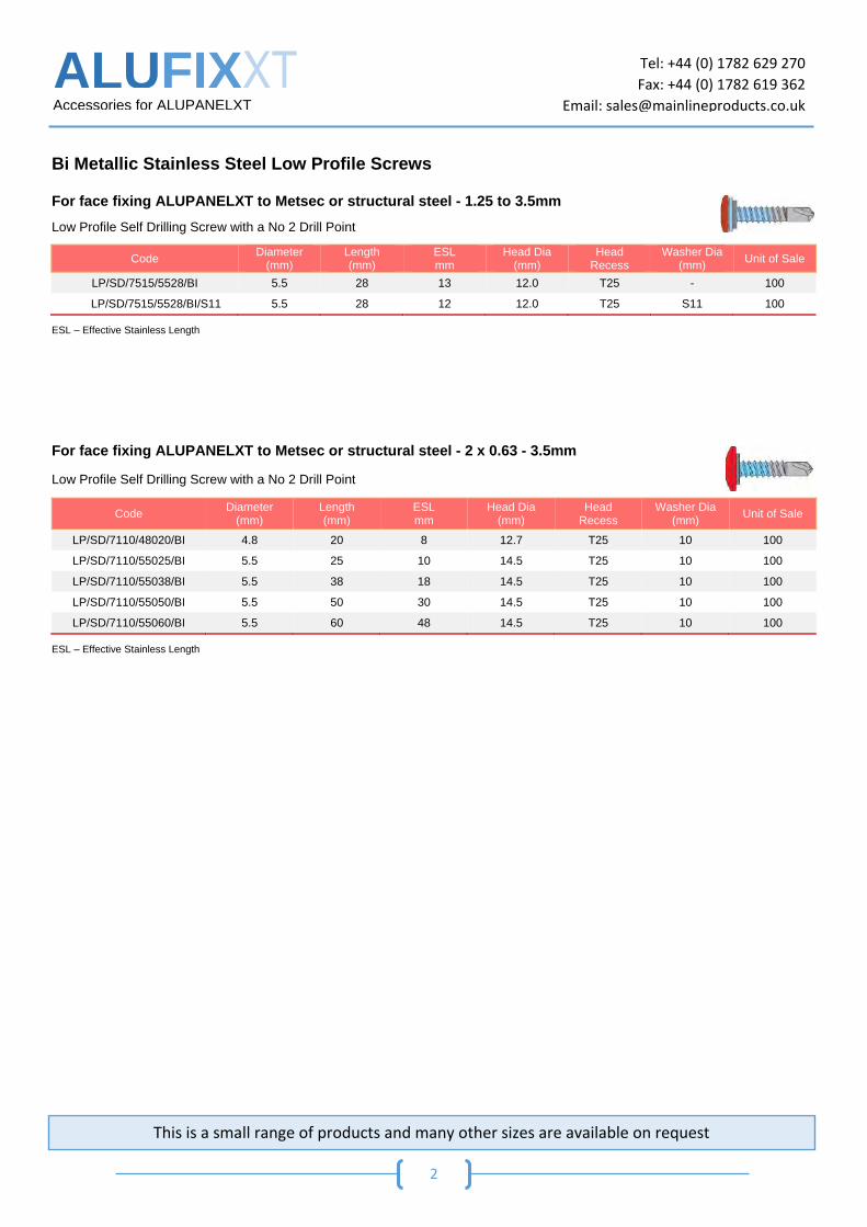
Bi Metallic Stainless Steel Low Profile Screws
For face fixing ALUPANELXT to Metsec or structural steel - 1.25 to 3.5mm
Low Profile Self Drilling Screw with a No 2 Drill Point
Code Diameter
(mm) Length (mm)
ESL mm
Head Dia (mm)
Head Recess
Washer Dia (mm)
Unit of Sale
LP/SD/7515/5528/BI 5.5 28 13 12.0 T25 - 100
LP/SD/7515/5528/BI/S11 5.5 28 12 12.0 T25 S11 100
ESL – Effective Stainless Length
For face fixing ALUPANELXT to Metsec or structural steel - 2 x 0.63 - 3.5mm
Low Profile Self Drilling Screw with a No 2 Drill Point
ESL – Effective Stainless Length
Code Diameter
(mm) Length (mm)
ESL mm
Head Dia (mm)
Head Recess
Washer Dia (mm)
Unit of Sale
LP/SD/7110/48020/BI 4.8 20 8 12.7 T25 10 100
LP/SD/7110/55025/BI 5.5 25 10 14.5 T25 10 100
LP/SD/7110/55038/BI 5.5 38 18 14.5 T25 10 100
LP/SD/7110/55050/BI 5.5 50 30 14.5 T25 10 100
LP/SD/7110/55060/BI 5.5 60 48 14.5 T25 10 100
This is a small range of products and many other sizes are available on request

ALUFIXXT
Accessories for ALUPANELXT
Tel: +44 (0) 1782 629 270
Fax: +44 (0) 1782 619 362
Email: [email protected]
3
Aluminium Stainless Steel Rivets
Large Flange Rivet for face fixing ALUPANELXT to Aluminium Rail
Comprising of an aluminium (AlMg5) body with a stainless steel mandrel for face fixing ALUPANELXT to
aluminium rail.
Standard Flange Multi Grip Rivets for ALUPANELXT Cassettes
Comprising of an aluminium body with a stainless steel mandrel for the fabrication of ALUPANELXT
cassettes.
Countersunk Rivets for ALUPANELXT Cassettes
Comprising of an aluminium body with a stainless steel mandrel for the fabrication of .ALUPANELXT
cassettes.
Special Tooling for Rivets
Step Drills
Product Code
Hole Size (First
Diameter)
Hole Size (Second
Diameter) Description
Unit of Sale
STEP-051070 5.1 7.0 Used when securing a 5.0mm Rivet into a building Board 1
STEP-051085 5.1 8.5 Used when securing a 5.0mm Rivet into a building Board 1
Code Diameter
(mm) Length (mm)
Flange (mm)
Grip Range Units of Sale Min (mm) Max (mm)
SSAL5/501211AS 5.0 12 11 6.0 8.0 100
SSAL5/501214AS 5.0 12 14 6.0 8.0 100
Code Diameter
(mm) Length (mm)
Flange (mm)
Grip Range Unit of Sale Min (mm) Max (mm)
RBD32095/AS/MG 3.2 9.5 6.5 1.5 6.0 100
RBD40095/AS/MG 4.0 9.5 8.0 3.0 6.0 100
RBD48100/AS/MG 4.8 10.0 9.9 1.5 6.0 100
Code Diameter
(mm) Length (mm)
Flange (mm)
Grip Range (mm)
Unit Of Sale
RBC4812AS 4.8 12 120°Csk 6.0 – 8.0 100
This is a small range of products and many other sizes are available on request

ALUFIXXT
Accessories for ALUPANELXT
Tel: +44 (0) 1782 629 270
Fax: +44 (0) 1782 619 362
Email: [email protected]
4
Stainless Steel Rivets – Suitable for Harsh Environments
Large Flange Rivets for face fixing ALUPANELXT to Metsec or structural steel
Comprising of a stainless steel body with a stainless steel mandrel for face fixing ALUPANELXT to
Metsec and structural steel. Ideal for areas where increased corrosion resistance is required.
Standard Flange Multi Grip Rivets for ALUPANELXT Cassettes
Comprising of a stainless steel body with a stainless steel mandrel for fixing ALUPANELXT cassettes in
Harsh Marine Environments.
Countersunk Rivets for ALUPANELXT Cassettes
Comprising of a stainless steel body with a stainless steel mandrel for the fabrication of ALUPANELXT
cassettes in Harsh Environments.
Code Diameter (mm) Length (mm) Flange (mm) Grip Range
(mm) Unit
of Sale
SSSS4812 4.8 12 16 6.0 – 8.0 100
SSSS4814 4.8 14 16 8.0 – 10.0 100
Code Diameter (mm) Length (mm) Flange (mm) Grip Range
(mm) Unit
of Sale
RBD4012SS 4.0 12 8.0 6.0 - 8.0 100
RBD4812SS 4.8 12 9.5 6.0 - 8.0 100
Code Diameter (mm) Length (mm) Flange (mm) Grip Range
(mm) Unit
of Sale
RBC4012SS 4.0 12 8.0 6.0 - 8.0 100
RBC4812SS 4.8 12 9.5 6.0 - 8.0 100
This is a small range of products and many other sizes are available on request

ALUFIXXT
Accessories for ALUPANELXT
Tel: +44 (0) 1782 629 270
Fax: +44 (0) 1782 619 362
Email: [email protected]
5
Tools and Accessories
Centralising Tools
A centralising tool is used on predrilled panels to drill a concentric hole in the rail behind the panel. This will guarantee that rivets will be cantered both in the panel and the rail system. This tool can be used for drilling into timber – please see details on the Drills below
Code Panel Hole Size (mm)
Drill Dia (mm)
Rivet Body Dia (mm)
Board Manufacturer Units of
Sale
CT7051 7.0mm 5.1mm 5.0mm ALUPANELXT Panels - Under 1 Meter 1
CT8051 8.0mm 5.1mm 5.0mm ALUPANELXT Panels - Over 1 Meter 1
Spare Drill Bits for Centralising Tool
Code Diameter Description Units of Sale
CT-HDRLG5.1 5.1mm Specially designed Drill bit for Centralising Tools 1
CT-STEP-051030 5.1mm Specially designed Drill bit for Centralising Tools when there is a need to centralise the Screw into timber battens.
1
Rivet Spacer Nose Pieces
A Rivet spacer nose pieces’ primary function is to prevent clamping of the panel too tightly against the support frame, so as to allow
panel movement due to thermal changes.
Product Code Description Unit of Sale
RT/ACB/NP Nose Piece - Hex for Stainless Steel K16 Rivet 1
RT/ACB/NP/OD20 Nose piece 20mm O/D - for Stainless Steel K16 Rivet 1
RT/ACB/NP/AL/K11 Nosepiece 50mm O/D – ALUPANELXT K11 Rivet 1
RT/ACB/NP/AL/K14 Nosepiece 50mm O/D - ALUPANELXT K14 Rivet 1
ALUFIXXT
Accessories for ALUPANELXT
Tel: +44 (0) 1782 629 270
Fax: +44 (0) 1782 619 362
Email: [email protected]
6
Tapes and Gaskets
Flexible Finned Joint Gasket for Timber
To create a black shadowline between vertical timber panel joints
PVC Shadow-line Tape
To create a black shadowline between panels.
Self-Adhesive Gasket for Aluminium Rails
A barrier between the panel and aluminium rail to help reduce vibration between panel and rail.
Product Code Width Length on Roll Units of Sale
GAS/FIN/36/BLACK 36mm 25 Mtr 1
GAS/FIN/60/BLACK 60mm 25 Mtr 1
GAS/FIN/75/BLACK 75mm 25 Mtr 1
GAS/FIN/100/BLACK 100mm 25 Mtr 1
Product Code Width Length on Roll Units of Sale
GAS/SHL/050/PVC 50mm 33 Mtr 1
GAS/SHL/075/PVC 75mm 33 Mtr 1
GAS/SHL/100/PVC 100mm 33 Mtr 1
GAS/SHL/120/PVC 120mm 33 Mtr 1
Product Code Width Length on Roll Units of
Sale
GAS/FLT/SA/035/1 35mm 25 Mtr 1
GAS/FLT/SA/050/1 50mm 25 Mtr 1
GAS/FLT/SA/060/1 60mm 25 Mtr 1
GAS/FLT/SA/080/1 80mm 25 Mtr 1
GAS/FLT/SA/100/1 100mm 25 Mtr 1

ALUFIXXT
Accessories for ALUPANELXT
Tel: +44 (0) 1782 629 270
Fax: +44 (0) 1782 619 362
Email: [email protected]
7
Aluminium Profiles
Vent Profiles
To maintain a vertical air flow throughout the façade whilst keeing bugs, birds and vermin at bay.
Product Code Up stand
(mm)
Vented Diameter
(mm)
Free Ventilation Across Section
cm2/mm Length Colour
Pack Size
VP30030MF 30 30 92/92 2.5 Meters Natural 20
VP30040MF 30 40 92/139 2.5 Meters Natural 20
VP30050MF 30 50 92/185 2.5 Meters Natural 20
VP30060MF 30 60 208 2.5 Meters Natural 10
VP30070MF 30 70 254 2.5 Meters Natural 10
VP30090MF 30 90 346 2.5 Meters Natural 10
VP30100MF 30 100 393 2.5 Meters Natural 10
VP30120MF 30 120 462 2.5 Meters Natural 10
VP50050MF 50 50 185/185 2.5 Meters Natural 20
VP50700MF 50 70 185/255 2.5 Meters Natural 20
Where Free Vent shows two figures i.e. 185/185 it is vented both sides
Product Code Up stand
(mm)
Vented Diameter
(mm)
Free Ventilation Across Section
cm2/mm Length Colour
Pack Size
VP30040BL 30 40 92/139 2.5 Meters Black 20
VP30050BL 30 50 92/185 2.5 Meters Black 20
VP30060BL 30 60 208 2.5 Meters Black 10
VP30070BL 30 70 254 2.5 Meters Black 10
VP30100BL 30 100 393 2.5 Meters Black 10
VP30120BL 30 120 462 2.5 Meters Black 10
VP50050BL 50 50 185/185 2.5 Meters Black 20
VP50070BL 50 70 185/255 2.5 Meters Black 20
Where Free Vent shows two figures i.e. 185/185 it is vented both sides

CONTINUOUS DEVELOPMENT. INTELLIGENT SOLUTIONS
Forgeway Ltd / Registered Office: Collett Way, Brunel Road Industrial Estate, Newton Abbot, Devon, TQ12 4PH, UK / Company Reg No. 07230689 / Registered in England and Wales
Tel: +44 (0) 1626 367 070 E-mail; [email protected]
FORMOA PANEL BONDING SYSTEM FOR MULTIPANEL PANELS; Alupanel, Alupanel XT, Product Formoa 017FE is a High Performance single component adhesive, with medium to high viscosity and very high adhesive strength. Formoa Panel Bonding System Features -Long term durability, elasticity* and performance -Optimal tension distribution -Adhesion to panels tested in accord with ‘AMES-006’ -Excellent moisture and weather resistance -Fast and straight forward installation/mounting Formoa Panel Bonding System Consists of; -Formoa 017FE, 290ml High Performance Adhesive, 290ml Cartridge. Part Number 91048 600ml High Performance Adhesive, 600ml FoilSausage. Part Number 91045 -Triangular Nozzle For applying Formoa 017FE Adhesive. Part Number 53027 -Forbond F5600 Double Sided Foam Tape, 2mm x 12mm x 40m. Part Number 73004 -Formoa Surface Activator Simultaneous cleaner and degreaser, 1L. Part Number 92002

CONTINUOUS DEVELOPMENT. INTELLIGENT SOLUTIONS
Forgeway Ltd / Registered Office: Collett Way, Brunel Road Industrial Estate, Newton Abbot, Devon, TQ12 4PH, UK / Company Reg No. 07230689 / Registered in England and Wales
Tel: +44 (0) 1626 367 070 E-mail; [email protected]
Application The surfaces to be bonded must be clean; free from dust and grease. Use Formoa Surface activator or Suitable Industrial Solvent (Heptane, Isopropyl Alcohol) to clean mounting profile and back of the panel. When using Formoa Surface Activator, apply in one direction only using a lint free wipe. Take care to ensure Formoa Surface Activator or Industrial Solvent does not come in contact with the decorative front of the panel. Allow 10 minutes for Formoa Surface Activator or Industrial Solvent to flash off/dry. Apply the Forbond F5600 tape to the mounting profile and press firmly to ensure full surface contact. Before applying the tape work out the optimum position and length of tape required, bear in mind the dimensions of both the mounting profile and the panel, always ensure there is sufficient space for the adhesive (when flattened out the adhesive will cover ±20mm area). Apply Formoa 017FE High Strength Adhesive to the mounting profile using a triangular nozzle. Remove Blue Release liner from the tape. Offer up the panels within 10-15 minutes of applying the Formoa 017FE High Strength Adhesive. Gently place the panel into the adhesive, and ensure correct positioning; small corrections are possible until the panel contacts the tape. Joint spacers can be used to aid positioning. As soon as you’re satisfied with the positioning apply pressure to the bond area to ensure full surface contact with the tape. The tape will offer the initial hold to allow the adhesive time to cure. Cautions Take care to ensure Formoa Surface Activator or Industrial Solvent does not come in contact with the decorative front of the panel. After applying Formoa 017FE adhesive to the mounting profile you must not leave it for longer than 15 minutes before offering up the panel, if 15 minutes is exceeded the adhesive may start to skin over/dry and no long offer a wet bond. If unsure how long ago the adhesives was applied a sample test can be carried out; simply touch the surface of the bead of adhesive, if wet adhesive transfers onto the finger the adhesive is still good to bond.
*Formoa 017FE has an Elongation at Break of >350% (DIN 53504)
X

CONTINUOUS DEVELOPMENT. INTELLIGENT SOLUTIONS
Forgeway Ltd / Registered Office: Collett Way, Brunel Road Industrial Estate, Newton Abbot, Devon, TQ12 4PH, UK / Company Reg No. 07230689 / Registered in England and Wales
Tel: +44 (0) 1626 367 070 E-mail; [email protected]
FORBOND FABRICATION TAPE
FOR MULTIPANEL PANELS; Alupanel, Alupanel XT, Product Forbond F4150 is an adhesive tape, incorporating a unique adhesive system that provides fast adhesive strength build, high ultimate adhesive levels and long term performance. Forbond Fabrication Tape Features -Exceptional peel performance -Distribution of stress throughout the entire bond area -Excellent Weathering Properties -High bond Strength, especially in joints of high movement and different thermal expansion Forbond Fabrication Tape System Consists of; -Forbond F4150 Adhesive Tape, 1.1mm x 12mm x 33m. Part Number 76018
(Also Available in other dimensions) -IPA Surface Cleaner For removing dust and grease from bond area
prior to Appling the tape. Part Number 12007 -Hand roller Apply pressure and ensure full surface contact. Part Number 27001
Applications -Panel overlap joints -Bonding Stiffeners -Bonding cap profiles Application Best Practices -Ensure the surfaces to be joined with Forbond F4150 are clean; free of dust and grease. Use IPA surface Cleaner or a 50/50 isopropyl alcohol/water mixture to remove any contaminates, dust or grease. -After applying the tape, apply firm pressure to the bond area to ensure full contact. Cautions In temperatures below 15°C (well above our average autumn temperature of 10.9°C and winter temperature of 3.9°C) the lap sheer strength (strength of bond under extreme tension) of double-sided acrylic adhesive tape can be reduced by up to 50%.

CONTINUOUS DEVELOPMENT. INTELLIGENT SOLUTIONS
Forgeway Ltd / Registered Office: Collett Way, Brunel Road Industrial Estate, Newton Abbot, Devon, TQ12 4PH, UK / Company Reg No. 07230689 / Registered in England and Wales
Tel: +44 (0) 1626 367 070 E-mail; [email protected]
FORMOA COLOUR MATCHED SEALANT FOR MULTIPANEL PANELS; Alupanel, Alupanel XT, Product Formoa 010 is colour matched sealant, available in over 140 colours- every colour formulated to meet a customer need, with the ability to bespoke match to any substrate or colour reference. Formoa 010 is for applications where exact colour match is desired with no diminution in performance when exposed to extreme conditions and demanding environments. Formoa Colour Matched Sealant Features -Excellent adhesion to a range of substrates -Exceptional UV stability -Anti-Pick Properties -Solvent and isocyanate free -Available in an Anti-Microbial formula for applications where exceptional hygiene is required e.g. Washrooms and Medical Environments -Available in a Fire-Retardant formula for applications requiring rigid fire specifications Formoa 010 Coloured Sealant; Recommended Colour matches to Multipanel Décors
Multipanel; Panel Colour Reference Formoa Sealant Colour match; Part Number
Traffic White 9016 93029
Ultra White 91001
Light Ivory 1015 93060
Traffic Grey 7042 93067
Anthracite Grey 7016 93030
Ultra Marine Blue 5002 93038
Blue 5022 93014
Green 6005 93049
Traffic Green 6024 93276
Traffic Yellow 1023 93021
Orange 2004 93019
Traffic Red 3020 93068
Burgundy Red 3004 93024
Chocolate 8011 93273
Jet Black 9005 93165
Silver 9006 93140
Metallic Silver 93140
Brushed Aluminium 93272
Brushed Copper Gold 93293
Brushed Gold 93314
Brushed Black 93165

Fabrication Guidelines
APPENDIX 2 - Machine Manufacturer Information

Recommendations by Manufacturer
Recommendationsby Manufacturer
a multitude of applications
Recommended Routing Depth: Material thickness remaining after routing is usually between 1,5 -2 times skin thickness
Alupanel 0.45 - 0.6
Alupanel Light 0.35 (not recommended)
Ecopanel 0.25 (not recommended)
Note: All data obtained after in-house testing by manufacturer’s stated above.
Material Tested: Alupanel 3mm (0.3)
For Alupanel 2mm, Alupanel 2mm Lite and 3mm Lite we would recommend comparable speeds as stated above.
We always recommend that you allow time for your own indivdual test procedures, depending on Machine Version and always seek advice from an experienced user.
If further detail is requiered please contact your re-seller.
Maximum RPM 40000 rpm 55000 rpm 46600 rpm 50000 rpm 24000 rpm 24000 rpm 24000 rpmof Spindle
Type of tool BIT - MUS06- BIT - MUS06- R104 4 mm 4 mm CP-AL 4-8-6 90deg 6mm (4mm cutter) 4006-50C1 4006-50C1 V-groove End Mill
Recommended 83 mm/s 200 mm/s 200 mm/s 250 mm/s 85 mm/s 350 mm/s 320 mm/sFeed Rate approx approx

Routing & Folding 09
Additional Manufacturer Information
The additional information contained has been supplied by your chosen manufacturer:

Additional Manufacturer Information
Bit used for ACM
BIT- MUS06-2006-50C1 2 mm diameter BIT- MUS06-3006-50C1 3 mm diameter BIT- MUS06-4006-50C1 4 mm diameter
XP XN 5 m/min 5 m/min 50 % ACC 80 ACC z : 1m/min z : 1m/min TR/MN : 40 000 TR/MN : 40 000
XP XN
12 m/min 12 m/min50 % ACC 80 ACC z : 1m/min z : 1m/minTR/MN : 55 000 TR/MN : 55 000
ACM MultipanelSetting Kongsberg
1 kw Spindle 3 kw Spindle

Additional Manufacturer Information

Additional Manufacturer Information
For more information or CNC cutter sales:
Email : [email protected]él. : +44 (0) 1275 342 668Fax. : +44 (0) 1275 342 669
General Guidelines
Cutter Choice
Cutting Multipanel Sheet Materials
Pliage de matériaux en feuille Multipanel
Copyright Tekcel CNC Solutions 2012
Machine Fold Lines
Cut Out in One Pass
Tekcel CP-AL Cutters
Tekcel GP Cutters
Tekcel FC Cutters
Accurate Depth Control
Perfect Results
FOLDING / CUTTING MULTIPANEL SHEET PRODUCTS
Product Code Cutting Dia. Max. Cut Length Shank Dia.
CP-A1 3-6-6 3 mm 6 mm 6 mm
CP-A1 3-6-6 4 mm 8 mm 6 mm
CP-A1 3-6-6 6 mm 14 mm 6 mm
Product Code Angle Shank Dia.
FC-90 3 mm 8 mm
FC-135 4 mm 8 mm
Product Code Cutting Dia. Max. Cut Length Shank Dia.
GP 2-10-6 2 mm 10 mm 6 mm
GP 3-12-6 3 mm 12 mm 6 mm
GP 4-15- 6 4 mm 15 mm 6 mm
GP 6-20-6 6 mm 20 mm 6 mm

Additional Manufacturer Information
ACM Multipanel Setting Zund
Applicable bits:
R104 4 mm diameterR105 5 mm diameter R106 6 mm diameter
Routing speeds:
XY speed = 200 mm/sAcceleration = 4 (100 %)Router speed = 46600 Tr/mn

14 Additional Manufacturer Information

Technical specifications
For photographic reasons some units are without protections. The use of the machine must be made with all protections installed.
Overall dimensions
Panel height min-max min 3 - max 36 mm - Alu-Honeycomb min 10 max 15 mm
Panel width min. 110 mm
Panel length min. 120 mm
Variable feeder speed from 2 mt/1’ to 8 mt/1’ - from 6 FT to 26 FT
Milling motor 1 before bending rollers 200 Hz - 12.000 RPM - 0,50 kW
Milling motor 2 before bending rollers 200 Hz - 12.000 RPM - 0,50 kW Std. - 0,73 Opt.
Flush trimming motors after bending rollers 200 Hz - 12.000 RPM - 0,22 kW
Cutterhead - TCT cutters ø 80 mm Z10 - hole ø 16 mm
Total power installed ca. 1,5 KW
Via Tane di Baragone, 11
47899 Serravalle - Zona Ind.le Galazzano
Repubblica di San Marino
Tel. (+378) 0549/900720 - Fax (+378) 0549/955010
Manufactured by:
Automatic chain feeding millingand bending machine
ca. 610 Kg.
ACM
ALU HONEYCOMB
BEFORE
AFTER
HPL
BEFORE
AFTER
BEFORE
AFTER
Full control of machinefrom ergonomic panel
0°
90°
Flush trimmers after bending rollers
Numerical indicators for adjustments Copying disc
Combined Widia
Nr. 10 Bending rollersThey bend ACM and alu honeycomb panels
Adjustment with tilting indicators 0° -92°Independent adjustment from tilting
Milling unit before bending rollersNumerical indicator for adjustments
Groups 1 and 2 for Alu-Honeycomb panels up to 15 mmGroup 2 for HPL overlapping
-HPL edge milling-ACM milling for next bending
-honeycomb milling and bending line engraving
1 2
ww
w.c
asad
ei-i
nd
ustr
ia.c
omAdditional Manufacturer Information
Additional Manufacturer Information

Alupanel Fabrication Settings: MultiCam
Production Feedrate Max Feedrate575 IPM @ 35K 865 IPM @48K244mm/s @ 35K 366mm/s @ 48K
6mm Spiral O Upcut - Digital Express
Production Feedrate Max Feedrate700 IPM @ 35K 960 IPM @ 48K296mm/s @ 35K 406mm/s @ 48K
108 Degree ACm V Groove Bit - Digital Express
Production Feedrate Max Feedrate330 IPM @ 20K 550 IPM @ 30K140mm/s @ 20K 232mm/s @ 30K
6mm Spiral O Upcut - Router
Production Feedrate Max Feedrate400 IPM @ 20K 600 IPM @ 30K170mm/s @ 20K 254mm/s @ 30K
108 Degree ACm V Groove Bit - Router
www.multicam.com 972.929.4070
Additional Manufacturer Information

UK Head Office Tel +44 (0)1392 823015USA Office Tel +1 718 841 9940
www.multipanluk.co.uk