Embed Size (px)
Citation preview
Fabrication and tolerances of optics for HCPV P. Benitez , Juan C. Miñano , H. Ahmadpnahi , J. Mendes-Lopes , P. Zamora
Abstract: High Concentration Photovoltaics (HCPV) require an optical system with high efficiency, low cost and large tolerance. We describe the particularities of the HCPV applications, which constrain the optics design and the manufacturing techonologies.
1. Introduction Minimizing energy cost (€/kWh) is necessary for the success of concentrated photovoltaic energy (CPV). Key to minimizing this cost is an efficient and low cost optical design, goals best met with the fewest elements and the maximum tolerances, but always maintaining the high concentration (>500) that offsets the cost of expensive high-efficiency multi-junction solar cells [1]. CPV optical systems have usually only two stages (Primary and Secondary Optical Elements, or POE and SOE, respectively). This is because as the number of stages grows, the system becomes more complex and less efficient and as the number of stages reduces the concentration and the tolerance decreases. The POE is the first element intercepting the incoming solar energy. It is thus an element having a relative large area. The SOE is a smaller element which is either reflective or refractive.
Comparing to other optical components in other applications, CPV optics has two main singularities: (a) the cost targets constrain dramatically the fabrication technologies, and (b) the non-linear electrical performance of series connected solar cells affects the merit function for tolerancing.
2. Manufacturing technologies Manufacturing technology is a key issue when dealing with optical concentrators for CPV. A proper choice on the technology and materials employed in their manufacturing process may lead to cost-effective systems. The manufacturing technologies for CPV concentrators can be clearly divided into those for the POE and those for the SOE.
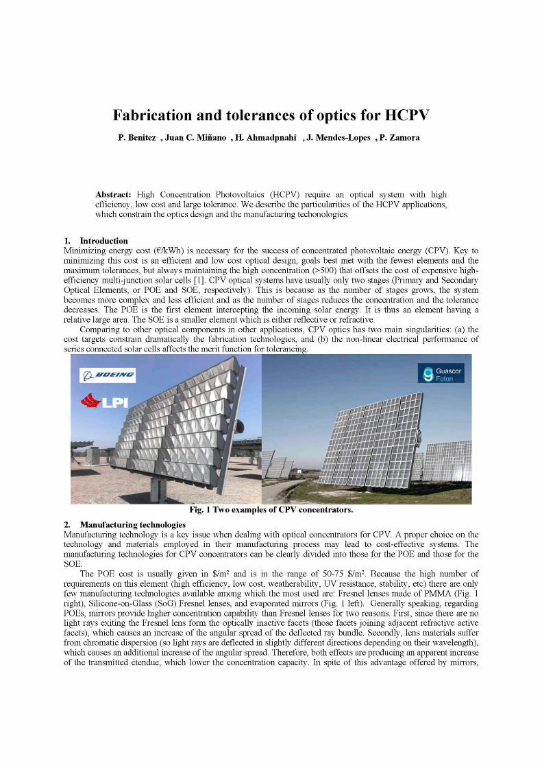
The POE cost is usually given in $/m2 and is in the range of 50-75 $/m2. Because the high number of requirements on this element (high efficiency, low cost, weatherability, UV resistance, stability, etc) there are only few manufacturing technologies available among which the most used are: Fresnel lenses made of PMMA (Fig. 1 right), Silicone-on-Glass (SoG) Fresnel lenses, and evaporated mirrors (Fig. 1 left). Generally speaking, regarding POEs, mirrors provide higher concentration capability than Fresnel lenses for two reasons. First, since there are no light rays exiting the Fresnel lens form the optically inactive facets (those facets joining adjacent refractive active facets), which causes an increase of the angular spread of the deflected ray bundle. Secondly, lens materials suffer from chromatic dispersion (so light rays are deflected in slightly different directions depending on their wavelength), which causes an additional increase of the angular spread. Therefore, both effects are producing an apparent increase of the transmitted étendue, which lower the concentration capacity. In spite of this advantage offered by mirrors,
Fresnel lenses present several key optical and practical features affecting the system cost that make them preferable as POEs, hence making Fresnel-based concentrators a preferable solution at present. This include the higher long-term reliability of Fresnel lenses, the higher sensitivity of mirrors to manufacturing error, and the usual shading of the receiver (usually facing downwards).
PMMA Fresnel lenses for CPV are being manufactured using three techniques: (a) PMMA injection molding, (b) hot-embossing of PMMA plates, and (c) hot-embossing of PMMA films that are later laminated onto a PMMA plate. The injection molding technique is particularly adequate when the designed Fresnel lens is not flat, but the vertices corner radii are larger than with the other techniques. The main advantage of embossing is the ability to produce large volumes of large area lenses at a lower cost than that obtained through injection molding. In the embossing process for Fresnel lens manufacture, the master can be either flat (stamper-based method) for the (b) case in which a plate is embossed or cylindrical (roller-based method) for the (c) case in which a film is embossed. On the other hand, SoG lenses are composed of a superstrate of transparent glass and, attached to it, a thin layer of silicone with the printed facets performing the refractive function, preferably produced by casting. Despite SoG Fresnel lenses do not suffer from warp as PMMA ones do (mainly due to water absorption), they present an important practical drawback. As the silicone has a much larger dependence with temperature of the refractive index than the PMMA, and moreover the different CTE of glass and silicone produce deformation of the Fresnel facets when temperature varies, producing an increase of the size of the focal spot [2].
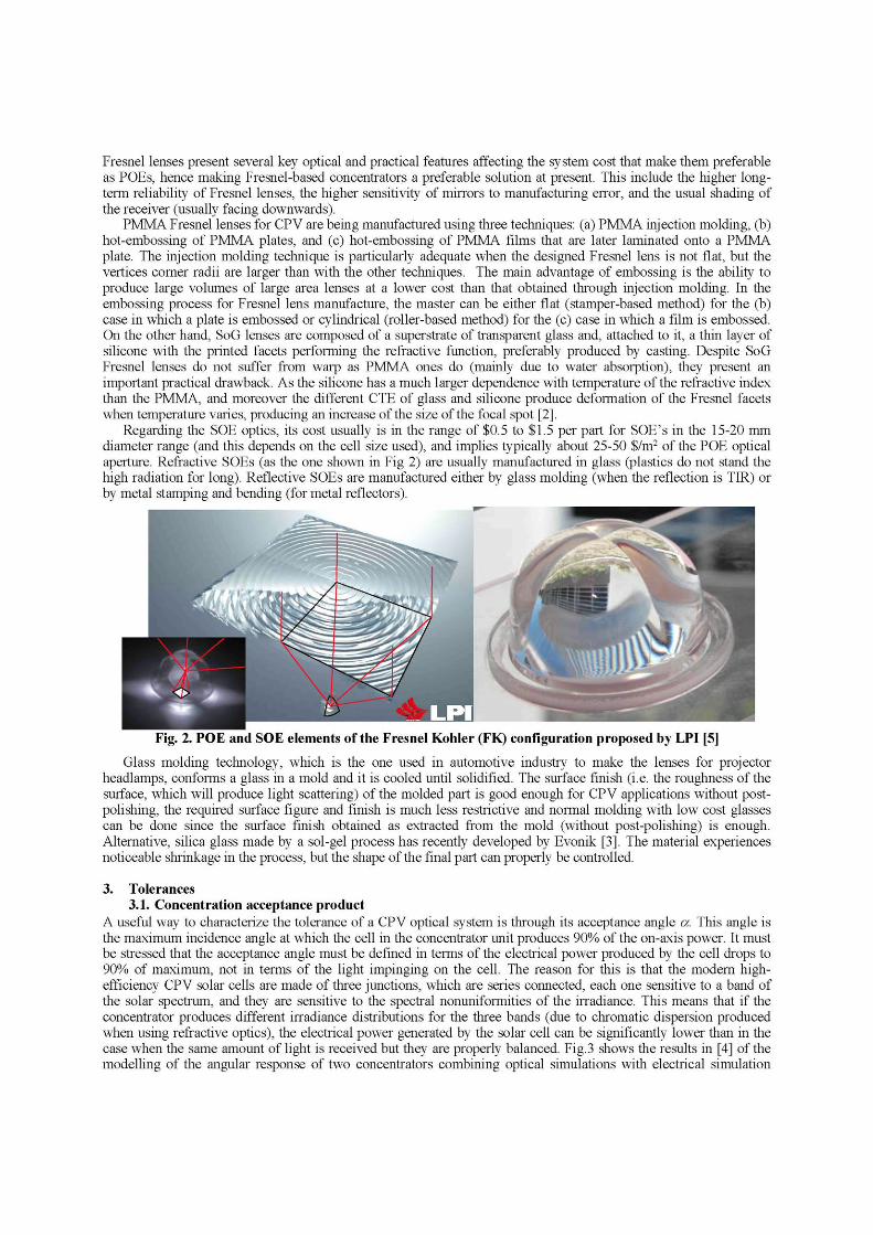
Regarding the SOE optics, its cost usually is in the range of $0.5 to $1.5 per part for SOE’s in the 15-20 mm diameter range (and this depends on the cell size used), and implies typically about 25-50 $/m2 of the POE optical aperture. Refractive SOEs (as the one shown in Fig 2) are usually manufactured in glass (plastics do not stand the high radiation for long). Reflective SOEs are manufactured either by glass molding (when the reflection is TIR) or by metal stamping and bending (for metal reflectors).
Fig. 2. POE and SOE elements of the Fresnel Kohler (FK) configuration proposed by LPI [5]
Glass molding technology, which is the one used in automotive industry to make the lenses for projector headlamps, conforms a glass in a mold and it is cooled until solidified. The surface finish (i.e. the roughness of the surface, which will produce light scattering) of the molded part is good enough for CPV applications without post-polishing, the required surface figure and finish is much less restrictive and normal molding with low cost glasses can be done since the surface finish obtained as extracted from the mold (without post-polishing) is enough. Alternative, silica glass made by a sol-gel process has recently developed by Evonik [3]. The material experiences noticeable shrinkage in the process, but the shape of the final part can properly be controlled.
3. Tolerances 3.1. Concentration acceptance product
A useful way to characterize the tolerance of a CPV optical system is through its acceptance angle a. This angle is the maximum incidence angle at which the cell in the concentrator unit produces 90% of the on-axis power. It must be stressed that the acceptance angle must be defined in terms of the electrical power produced by the cell drops to 90% of maximum, not in terms of the light impinging on the cell. The reason for this is that the modern high-efficiency CPV solar cells are made of three junctions, which are series connected, each one sensitive to a band of the solar spectrum, and they are sensitive to the spectral nonuniformities of the irradiance. This means that if the concentrator produces different irradiance distributions for the three bands (due to chromatic dispersion produced when using refractive optics), the electrical power generated by the solar cell can be significantly lower than in the case when the same amount of light is received but they are properly balanced. Fig.3 shows the results in [4] of the modelling of the angular response of two concentrators combining optical simulations with electrical simulation
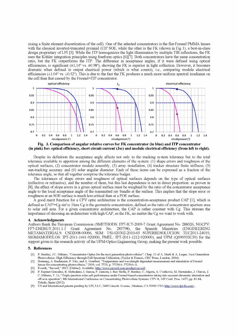
(using a finite element discretization of the cell). One of the selected concentrators is the flat-Fresnel PMMA lenses with the classical inverted-truncated pyramid (ITP SOE, while the other is the FK (shown in Fig 1), a best-in-class design proprietary of LPI [5]. While the ITP homogenizes the light illumination by multiple TIR reflections, the FK uses the Köhler integration principles using freeform optics [6][7]. Both concentrators have the same concentration ratio, but the FK outperforms the ITP. The difference in acceptance angles, if it were defined using optical efficiencies, is significant (±1,14º vs. ±0.98º), showing the FK is superior in light collection. However, it becomes dramatic when defined in output electrical power (which is what counts), i.e., comparing module electrical efficiencies (±1.04º vs. ±0.52º). This is due to the fact the FK produces a much more uniform spectral irradiance on the cell than that caused by the Fresnel+ITP concentrator.
Fig. 3. Comparison of angular relative curves for FK concentrator (in blue) and ITP concentrator (in pink) for: optical efficiency, short circuit current (Jsc) and module electrical efficiency (from left to right).
Despite its definition the acceptance angle affects not only to the tracking system tolerance but to the total tolerance available to apportion among the different elements of the system: (1) shape errors and roughness of the optical surfaces, (2) concentrator module assembly, (3) array installation, (4) tracker structure finite stiffness, (5) sun-tracking accuracy and (6) solar angular diameter. Each of these items can be expressed as a fraction of the tolerance angle, so that all together comprise the tolerance budget.
The tolerances of shape errors and roughness of optical surfaces depends on the type of optical surfaces (reflective or refractive), and the number of them, but this last dependence is not in direct proportion: as proven in [8], the effect of slope errors in a given optical surface must be weighted by the ratio of the concentrator acceptance angle to the local acceptance angle of the transmitted ray bundle at the surface. This implies that the slope error or roughness at an SOE surface is much less critical than at a POE surface.
A good merit function for a CPV optic architecture is the concentration-acceptance product CAP [1], which is defined as CAP2=Cg sin2a. Here Cg is the geometric concentration, defined as the ratio of concentrator aperture area to solar cell area. For a given concentrator architecture, the CAP is rather constant with Cg. This stresses the importance of choosing an architecture with high CAP, as the FK, no matter the Cg we want to work with.
4. Acknowledgments Authors thank the European Commission (SMETHODS: FP7-ICT-2009-7 Grant Agreement No. 288526, NGCPV: FP7-ENERGY.2011.1.1 Grant Agreement No. 283798), the Spanish Ministries (ENGINEERING METAMATERIALS: CSD2008-00066, SEM: TSI-020302-2010-65 SUPERRESOLUCION: TEC2011-24019, SIGMAMODULOS: IPT-2011-1441-920000, PMEL: IPT-2011-1212-920000), and UPM (Q090935C59) for the support given to the research activity of the UPM-Optics Engineering Group, making the present work possible.
5. References
[1] P. Benitez, J.C. Miñano, “Concentrator Optics for the next generation photovoltaics”. Chap. 13 of A. Marti & A. Luque. Next Generation Photovoltaics: High Efficiency through Full Spectrum Utilization, (Taylor & Francis, CRC Press, London, 2004).
[2] Hornung, A. Bachmaier, P. Nitz, and A. Gombert, “Temperature and wavelength dependent measurement and simulation of Fresnel lenses for concentrating photovoltaics,” 2010, vol. 7725, p. 77250A-77250A-6.
[3] Evonik, “Savosil,” 2013. [Online]. Available: http://www.savosil.com/product/savosil. [4] P. Espinet-González, R. Mohedano, I. García, P. Zamora, I. Rey-Stolle, P. Benitez, C. Algora, A. Cvetkovic, M. Hernández, J. Chaves, J.
C. Miñano, Y. Li, “Triple-junction solar cell performance under Fresnel-based concentrators taking into account chromatic aberration and off-axis operation”, 8th International Conference on Concentrating Photovoltaic Systems: CPV-8, AIP Conf. Proc. 1477, pp. 81-84, Toledo, Spain (2012).
[5] US and International patents pending by LPI, LLC, 2400 Lincoln Avenue, Altadena, CA 91001 USA http://www.lpi-llc.com/..

[6] J.C. Miñano, M. Hernandez, P. Benítez, J. Blen, O. Dross, R. Mohedano, A. Santamaría, “Free-form integrator array optics”, in Nonimaging Optics and Efficient Illumination Systems II, SPIE Proc., .Vol. 5942-12, (2005)
[7] P. Benítez, J.C. Miñano, P. Zamora, R. Mohedano, A. Cvetkovic, M. Buljan, J. Chaves, and M. Hernández, "High performance Fresnel-based photovoltaic concentrator," Opt. Express 18, A25-A40 (2010).
[8] R. Winston, J.C. Miñano, P. Benítez, “Manufacturing tolerances” Chapter 14 in Nonimaging Optics, (Elsevier, New York, 2005).