Embed Size (px)
Citation preview
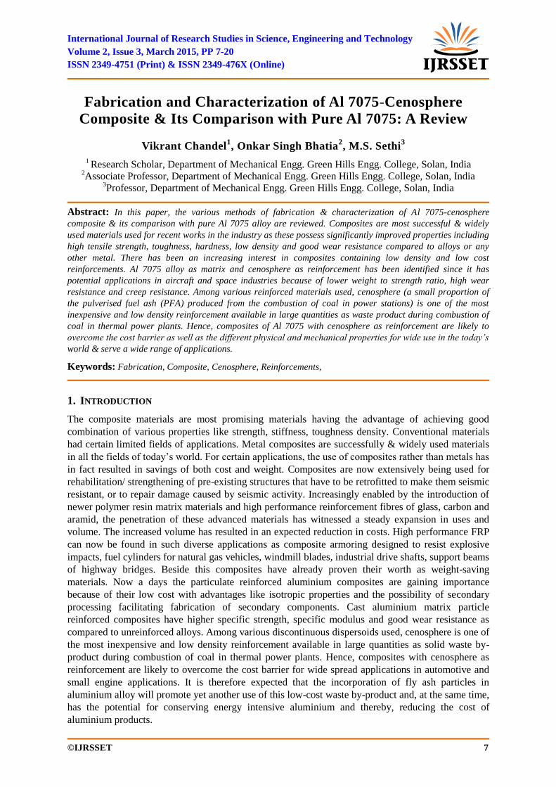
International Journal of Research Studies in Science, Engineering and Technology
Volume 2, Issue 3, March 2015, PP 7-20
ISSN 2349-4751 (Print) & ISSN 2349-476X (Online)
©IJRSSET 7
Fabrication and Characterization of Al 7075-Cenosphere
Composite & Its Comparison with Pure Al 7075: A Review
Vikrant Chandel1, Onkar Singh Bhatia
2, M.S. Sethi
3
1 Research Scholar, Department of Mechanical Engg. Green Hills Engg. College, Solan, India
2Associate Professor, Department of Mechanical Engg. Green Hills Engg. College, Solan, India
3Professor, Department of Mechanical Engg. Green Hills Engg. College, Solan, India
Abstract: In this paper, the various methods of fabrication & characterization of Al 7075-cenosphere
composite & its comparison with pure Al 7075 alloy are reviewed. Composites are most successful & widely
used materials used for recent works in the industry as these possess significantly improved properties including
high tensile strength, toughness, hardness, low density and good wear resistance compared to alloys or any
other metal. There has been an increasing interest in composites containing low density and low cost
reinforcements. Al 7075 alloy as matrix and cenosphere as reinforcement has been identified since it has
potential applications in aircraft and space industries because of lower weight to strength ratio, high wear
resistance and creep resistance. Among various reinforced materials used, cenosphere (a small proportion of
the pulverised fuel ash (PFA) produced from the combustion of coal in power stations) is one of the most
inexpensive and low density reinforcement available in large quantities as waste product during combustion of
coal in thermal power plants. Hence, composites of Al 7075 with cenosphere as reinforcement are likely to
overcome the cost barrier as well as the different physical and mechanical properties for wide use in the today’s
world & serve a wide range of applications.
Keywords: Fabrication, Composite, Cenosphere, Reinforcements,
1. INTRODUCTION
The composite materials are most promising materials having the advantage of achieving good
combination of various properties like strength, stiffness, toughness density. Conventional materials
had certain limited fields of applications. Metal composites are successfully & widely used materials
in all the fields of today‟s world. For certain applications, the use of composites rather than metals has
in fact resulted in savings of both cost and weight. Composites are now extensively being used for
rehabilitation/ strengthening of pre-existing structures that have to be retrofitted to make them seismic
resistant, or to repair damage caused by seismic activity. Increasingly enabled by the introduction of
newer polymer resin matrix materials and high performance reinforcement fibres of glass, carbon and
aramid, the penetration of these advanced materials has witnessed a steady expansion in uses and
volume. The increased volume has resulted in an expected reduction in costs. High performance FRP
can now be found in such diverse applications as composite armoring designed to resist explosive
impacts, fuel cylinders for natural gas vehicles, windmill blades, industrial drive shafts, support beams
of highway bridges. Beside this composites have already proven their worth as weight-saving
materials. Now a days the particulate reinforced aluminium composites are gaining importance
because of their low cost with advantages like isotropic properties and the possibility of secondary
processing facilitating fabrication of secondary components. Cast aluminium matrix particle
reinforced composites have higher specific strength, specific modulus and good wear resistance as
compared to unreinforced alloys. Among various discontinuous dispersoids used, cenosphere is one of
the most inexpensive and low density reinforcement available in large quantities as solid waste by-
product during combustion of coal in thermal power plants. Hence, composites with cenosphere as
reinforcement are likely to overcome the cost barrier for wide spread applications in automotive and
small engine applications. It is therefore expected that the incorporation of fly ash particles in
aluminium alloy will promote yet another use of this low-cost waste by-product and, at the same time,
has the potential for conserving energy intensive aluminium and thereby, reducing the cost of
aluminium products.
Fabrication and Characterization of Al 7075-Cenosphere Composite & Its Comparison with Pure Al
7075: A Review
International Journal of Research Studies in Science, Engineering and Technology [IJRSSET] 8
2. COMPOSITE
A composite is a structural material that consists of two or more combined constituents that are
combined at a macroscopic level and are not soluble in each other. One constituent is called the
reinforcing phase and the one in which it is embedded is called the matrix. The reinforcing phase
material may be in the form of fibers, particles, or flakes. The matrix phase materials are generally
continuous. Examples of composite systems include concrete reinforced with steel and epoxy
reinforced with graphite fibers etc. They are combined in such a way that the resulting composite
material or composite possesses superior properties .which are not obtainable with a single constituent
material. So, in technical terms, we can define a composite as a multiphase material from a
combination of materials, differing in composition or form, which remain bonded together, but retain
their identities and properties, without going into any chemical reactions. The components do not
dissolve or completely merge. They maintain an interface between each other and ad in concert to
provide improved, specific or synergistic characteristics not obtainable by any of the original
components acting singly.
3. CHARACTERISTICS OF COMPOSITES
Composites consist of one or more discontinuous phases embedded in a continuous phase. The
discontinuous phase is usually harder and stronger than the continuous phase and is called the
„reinforcement„ or „reinforcing material‟, whereas the continuous phase is termed as the „ matrix‟.
Properties of composites are strongly dependent on the properties of their constituent materials, their
distribution and the interaction among them. The composite properties may be the volume fraction
sum of the properties of the constituents or the constituents may interact in a synergistic way resulting
in improved or better properties.
Apart from the nature of the constituent materials, the geometry of the reinforcement (shape, size and
size distribution) influences the properties of the composite to a great extent.
4. CLASSIFICATION OF COMPOSITES
Composite materials may be classified into natural and synthetic composite materials but mainly
composites are classified into two phases-
Matrix and
Reinforcement phase.
Moreover the composites are classified by the geometry of the reinforcement ‒ particulates, flakes and
fibres or by the geometry of matrix – polymer, metal, ceramic and carbon.
Matrix is continuous and surrounds the discontinuous and other is Reinforcement phase. The purpose
of the matrix is to bind the reinforcements together by virtue of its cohesive and adhesive
characteristics, to transfer load to and between reinforcements, and to protect the reinforcements from
environments and handling. The reinforcements impart their special mechanical and physical
properties to enhance the matrix properties or replace some of the polymer volume with a less
expensive material- the filler. It is very important to remember that these components are highly or
strongly bonded together or stuck together, and are close and strong contacts with each other when
performing. The purpose of the reinforcement is making composite stronger and stiffer. The
reinforcing phase is of low density, strong, stiff and thermally stable. The major load on the composite
is beard by the reinforcing phase.
4.1. Particulate Composites
As the name itself indicates, the reinforcement is of particle nature (platelets are also included in this
class). It may be spherical, cubic, tetragonal, a platelet, or of other regular or irregular shape, but it is
approximately equiaxed. In general, particles are not very effective in improving fracture resistance
but they enhance the stiffness of the composite to a limited extent. Particle fillers are widely used to
improve the properties of matrix materials such as to modify the thermal and electrical conductivities,
improve performance at elevated temperatures, reduce friction, increase wear and abrasion resistance,
improve machinability, increase surface hardness and reduce shrinkage.
Vikrant Chandel et al.
International Journal of Research Studies in Science, Engineering and Technology [IJRSSET] 9
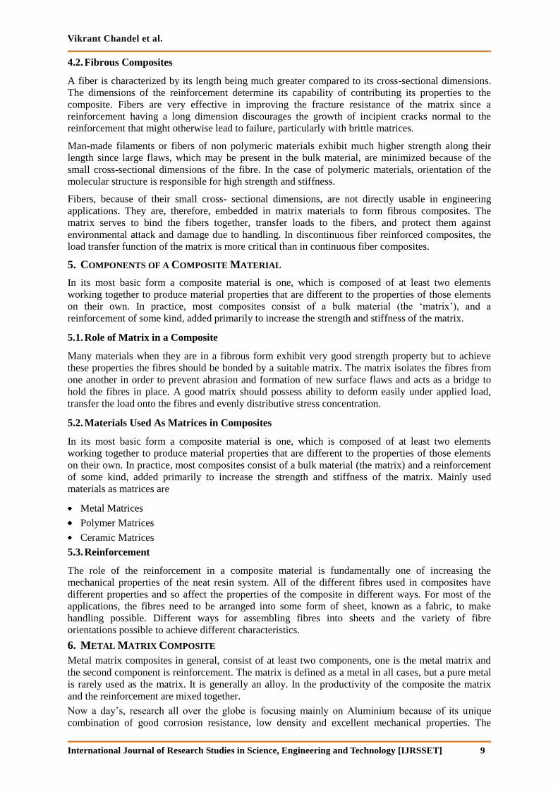
4.2. Fibrous Composites
A fiber is characterized by its length being much greater compared to its cross-sectional dimensions.
The dimensions of the reinforcement determine its capability of contributing its properties to the
composite. Fibers are very effective in improving the fracture resistance of the matrix since a
reinforcement having a long dimension discourages the growth of incipient cracks normal to the
reinforcement that might otherwise lead to failure, particularly with brittle matrices.
Man-made filaments or fibers of non polymeric materials exhibit much higher strength along their
length since large flaws, which may be present in the bulk material, are minimized because of the
small cross-sectional dimensions of the fibre. In the case of polymeric materials, orientation of the
molecular structure is responsible for high strength and stiffness.
Fibers, because of their small cross- sectional dimensions, are not directly usable in engineering
applications. They are, therefore, embedded in matrix materials to form fibrous composites. The
matrix serves to bind the fibers together, transfer loads to the fibers, and protect them against
environmental attack and damage due to handling. In discontinuous fiber reinforced composites, the
load transfer function of the matrix is more critical than in continuous fiber composites.
5. COMPONENTS OF A COMPOSITE MATERIAL
In its most basic form a composite material is one, which is composed of at least two elements
working together to produce material properties that are different to the properties of those elements
on their own. In practice, most composites consist of a bulk material (the „matrix‟), and a
reinforcement of some kind, added primarily to increase the strength and stiffness of the matrix.
5.1. Role of Matrix in a Composite
Many materials when they are in a fibrous form exhibit very good strength property but to achieve
these properties the fibres should be bonded by a suitable matrix. The matrix isolates the fibres from
one another in order to prevent abrasion and formation of new surface flaws and acts as a bridge to
hold the fibres in place. A good matrix should possess ability to deform easily under applied load,
transfer the load onto the fibres and evenly distributive stress concentration.
5.2. Materials Used As Matrices in Composites
In its most basic form a composite material is one, which is composed of at least two elements
working together to produce material properties that are different to the properties of those elements
on their own. In practice, most composites consist of a bulk material (the matrix) and a reinforcement
of some kind, added primarily to increase the strength and stiffness of the matrix. Mainly used
materials as matrices are
Metal Matrices
Polymer Matrices
Ceramic Matrices
5.3. Reinforcement
The role of the reinforcement in a composite material is fundamentally one of increasing the
mechanical properties of the neat resin system. All of the different fibres used in composites have
different properties and so affect the properties of the composite in different ways. For most of the
applications, the fibres need to be arranged into some form of sheet, known as a fabric, to make
handling possible. Different ways for assembling fibres into sheets and the variety of fibre
orientations possible to achieve different characteristics.
6. METAL MATRIX COMPOSITE
Metal matrix composites in general, consist of at least two components, one is the metal matrix and
the second component is reinforcement. The matrix is defined as a metal in all cases, but a pure metal
is rarely used as the matrix. It is generally an alloy. In the productivity of the composite the matrix
and the reinforcement are mixed together.
Now a day‟s, research all over the globe is focusing mainly on Aluminium because of its unique
combination of good corrosion resistance, low density and excellent mechanical properties. The
Fabrication and Characterization of Al 7075-Cenosphere Composite & Its Comparison with Pure Al
7075: A Review
International Journal of Research Studies in Science, Engineering and Technology [IJRSSET] 10
unique thermal properties of Aluminium composites such as metallic conductivity with coefficient of
expansion that can be tailored down to zero, add to their prospects in aerospace and avionics.
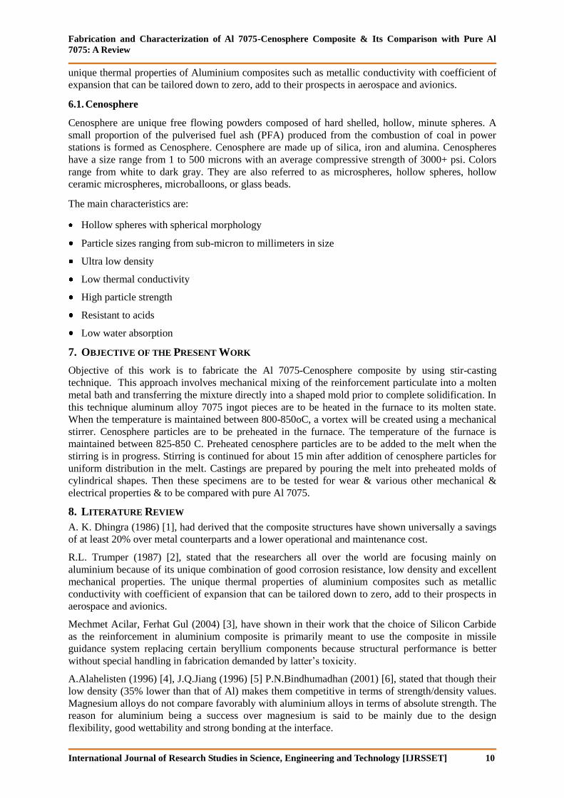
6.1. Cenosphere
Cenosphere are unique free flowing powders composed of hard shelled, hollow, minute spheres. A
small proportion of the pulverised fuel ash (PFA) produced from the combustion of coal in power
stations is formed as Cenosphere. Cenosphere are made up of silica, iron and alumina. Cenospheres
have a size range from 1 to 500 microns with an average compressive strength of 3000+ psi. Colors
range from white to dark gray. They are also referred to as microspheres, hollow spheres, hollow
ceramic microspheres, microballoons, or glass beads.
The main characteristics are:
Hollow spheres with spherical morphology
Particle sizes ranging from sub-micron to millimeters in size
Ultra low density
Low thermal conductivity
High particle strength
Resistant to acids
Low water absorption
7. OBJECTIVE OF THE PRESENT WORK
Objective of this work is to fabricate the Al 7075-Cenosphere composite by using stir-casting
technique. This approach involves mechanical mixing of the reinforcement particulate into a molten
metal bath and transferring the mixture directly into a shaped mold prior to complete solidification. In
this technique aluminum alloy 7075 ingot pieces are to be heated in the furnace to its molten state.
When the temperature is maintained between 800-850oC, a vortex will be created using a mechanical
stirrer. Cenosphere particles are to be preheated in the furnace. The temperature of the furnace is
maintained between 825-850 C. Preheated cenosphere particles are to be added to the melt when the
stirring is in progress. Stirring is continued for about 15 min after addition of cenosphere particles for
uniform distribution in the melt. Castings are prepared by pouring the melt into preheated molds of
cylindrical shapes. Then these specimens are to be tested for wear & various other mechanical &
electrical properties & to be compared with pure Al 7075.
8. LITERATURE REVIEW
A. K. Dhingra (1986) [1], had derived that the composite structures have shown universally a savings
of at least 20% over metal counterparts and a lower operational and maintenance cost.
R.L. Trumper (1987) [2], stated that the researchers all over the world are focusing mainly on
aluminium because of its unique combination of good corrosion resistance, low density and excellent
mechanical properties. The unique thermal properties of aluminium composites such as metallic
conductivity with coefficient of expansion that can be tailored down to zero, add to their prospects in
aerospace and avionics.
Mechmet Acilar, Ferhat Gul (2004) [3], have shown in their work that the choice of Silicon Carbide
as the reinforcement in aluminium composite is primarily meant to use the composite in missile
guidance system replacing certain beryllium components because structural performance is better
without special handling in fabrication demanded by latter‟s toxicity.
A.Alahelisten (1996) [4], J.Q.Jiang (1996) [5] P.N.Bindhumadhan (2001) [6], stated that though their
low density (35% lower than that of Al) makes them competitive in terms of strength/density values.
Magnesium alloys do not compare favorably with aluminium alloys in terms of absolute strength. The
reason for aluminium being a success over magnesium is said to be mainly due to the design
flexibility, good wettability and strong bonding at the interface.
Vikrant Chandel et al.
International Journal of Research Studies in Science, Engineering and Technology [IJRSSET] 11
S. Tjong (1997) [7], H.Z.Wang (1996) [8] & D.P.Mondal (2003) [9] concluded in their studies that
the reinforcement inconsistency will persist because many of the aspect cited above in addition to
contamination from processing equipment and feedstock may vary greatly. Since most ceramics are
available as particles, there is a wide range of potential reinforcements for particle reinforced
composites.
Ferdinand A.A. (1958) [10] & Elmer P. (1962) [11] have shown that that the use of graphite
reinforcement in a metal matrix has a potential to create a material with a high thermal conductivity,
excellent mechanical properties and attractive damping behaviour at elevated temperatures. However,
lack of wettability between aluminium and the reinforcement, and oxidation of the graphite lead to
manufacturing difficulties and cavitations of the material at high temperatures.
Thakur R.S. (1975) [12], Harvath G (1975) [13] & Muralidhar J. (1977) [14] have shown that the
alumina and other oxide particles like TiO2 etc. have been used as the reinforcing particles in Al-
matrix. Alumina has received attention as reinforcing phase as it is found to increase the hardness,
tensile strength and wear resistance of aluminium metal matrix composites.
Aggarwal P.S (1977) [15], Grigoreva.D. (1977) [16], Kudinov B.Z, (1977) [17], Pustilnik G.L. (1977)
[18] & Zamb J. (1979) [19] have concluded that mica, alumina, silicon carbide, clay, zircon, and
graphite have been widerly used as reinforcements in the production of composites. Numerous oxides,
nitrides, borides and carbides were studied by Zedalis as reinforcements for reinforcing high
temperature discontinuously reinforced aluminiumn (HTDRA). It has been inferred from their studies
that HTDRA containing TiC TiB2, B4C, Al2O3, SiC and Si3N4 exhibit the highest values of specific
stiffness.
Nikolaev (1983) [20], Stanescu N. (1990) [21], MinePet.Gaze & R. Mehrabian (1974) [22] proved
that the ceramic particles are effective reinforcement materials in aluminium alloy to enhance the
mechanical and other properties. The reinforcement in MMCs are usually of ceramic materials, these
reinforcements can be divided into two major groups, continuous and discontinuous. The MMCs
produced by them are called continuously (fibre) reinforced composites and discontinuously
reinforced composites. However, they can be subdivided broadly into five major categories:
continuous fibres, short fibres (chopped fibres, not necessarily the same length), whiskers, particulate
and wire (only for metal). With the exception of wires, reinforcements are generally ceramics,
typically these ceramics being oxides, carbides and nitrides. These are used because of their
combinations of high strength and stiffness at both room and elevated temperatures. Common
reinforcement elements are SiC, A1203, TiB2, boron and graphite.
J. Eliasson and R. Sandstorm (1995) [23], term fibre may be used for any material in an elongated
form that has a minimum length to a maximum average transverse dimension of 10:1, a maximum
cross sectional area of 5.1X10⁻⁴ cm2 and a maximum transverse dimension of 0.0254 cm. Continuous
fibers in composites are usually called filaments, the main continuous fibres includes boron, graphite,
alumina and silicon carbide. The fibre is unique for unidirectional load when it is oriented in the same
direction as that of loading, but it has low strength in the direction perpendicular to the fibre
orientation. As regards cost, continuous fibres are about 200 times higher than discontinuous fibres.
Therefore for specific purposes only, that continuous fibre is used. The other advantage of
discontinuous fibres is that they can be shaped by any standard metallurgical processes such as
forging, rolling, extrusion etc.
John E. Allison (1993) [24], D. J. Lloyd (1990) [25], M.G. McKimpson (1989) [26], H.J. Rack (1990)
[27], A. W. Urquhart (1991) [28], V. V. Bhanuprasad (1991) [29] & M. S. Zedias (1991) [30] showed
that the short fibres are long compared to the critical length (lc = d Sf / Sm where d is the fibre
diameter, Sf is the reinforcement strength and Sm is the matrix strength) and hence show high
strength in composites, considering aligned fibres. Nevertheless, misoriented short fibres have been
used with some success as AMC (Aluminium Matrix Composite) reinforcement. Short fibres are still
used mainly for refractory insulation purposes due to their low strength compared with others, but
they are cheaper than fibre and whisker.
R. A. Higgins (1986) [31] stated that whiskers are characterized by their fibrous, single crystal
structures, which have no crystalline defect. Numerous materials, including metals, oxides, carbides,
halides and organic compounds have been prepared under controlled conditions in the form of
Fabrication and Characterization of Al 7075-Cenosphere Composite & Its Comparison with Pure Al
7075: A Review
International Journal of Research Studies in Science, Engineering and Technology [IJRSSET] 12
whiskers. Generally, a whisker has a single dislocation, which runs along the central axis. The relative
freedom from discontinuous means that the yield strength of a whisker is close to the theoretical
strength of the material.
M.S. Zedias, P. S. Gilman and S.K.Das (1990) [32], silicon carbide whiskers seem to offer the best
opportunities for MMC reinforcement. Presently, silicon carbide whisker reinforcement is produced
from rice husk, which is a low cost material. The physical characteristics of whiskers are responsible
for different chemical reactivity with the matrix alloy and also health hazard posed in their handling.
Therefore the inherent interest shown by the researches in whiskers reinforcement has declined.
P. You (1987) [33], T. W. Clyne (1987) [34] & M. Gupta (1991) [35] have stated that the particulates
are the most common and cheapest reinforcement materials. These produce the isotropic property of
MMCs, which shows a promising application in structural fields. Initially, attempts were made to
produce reinforced Aluminium alloys with graphite powder but only low volume fractions of
reinforcement had been incorporated (<10%). Presently higher volume fractions of reinforcements
have been achieved for various kinds of ceramic particles (oxide, carbide, nitride). The SiCparticulate-
reinforced aluminium matrix composites have a good potential for use as wear resistant materials.
Actually, particulates lead to a favorable effect on properties such as hardness, wear resistance and
compressive strength.
D.Z. Yang (1995) [36] & D.J. Lloyd (1989) [37], D harles (1992) [38], Michael E (1987) [39] &
L.Geigr (1989) [40] the processing methods used to manufacture particulate reinforced MMCs can be
grouped as follows.
• Solid-Phase Fabrication Methods: diffusion bonding, hot rolling, extrusion, drawing, explosive
welding, PM route, pneumatic impaction, etc.
• Liquid-Phase Fabrication Methods: liquid-metal in filtration, squeeze casting, compocasting,
pressure casting, spray codeposition, stir casting etc.
• Two Phase (Solid/Liquid) Processes: Which include Rheocasting and Spray atomization. Normally
the liquid-phase fabrication method is more efficient than the solid-phase fabrication method
because solid-phase processing requires a longer time.
Herbert Dietrich (1991) [41], T.S. hester (1991) [42], M.V. Roode (1993) [43], D. Huda (1993) [44],
Alok Satapathy (2002) [45] & E. Hunt [46] stated that the attractive physical and mechanical
properties that can be obtained with metal matrix composites, such as high specific modulus, strength
and thermal stability, have been documented extensively. The various factors controlling the
properties of particulate MMCs and the influence of the manufacturing route on the MMC properties
has also been reviewed by several investigators. Improvement in modulus, strength, fatigue, creep and
wear resistance has already been demonstrated for a variety of reinforcements. Of these properties; the
tensile strength is the most convenient and widely quoted measurement and is of central importance in
many applications.
D. H. Kim, E.J. Lavernia and J. Earthman (1990) [47] have documented extensively the attractive
physical and mechanical properties that can be obtained with metal matrix composites, such as high
specific modulus, strength and thermal stability. The various factors controlling the properties of
particulate MMCs and the influence of the manufacturing route on the MMC properties has also been
reviewed by these investigators. Improvement in modulus, strength, fatigue, creep and wear resistance
has already been demonstrated for a variety of reinforcements. Of these properties; the tensile strength
is the most convenient and widely quoted measurement and is of central importance in many
applications.
P.J. Meachter and J.E. Oneil (1984) [48] stated that the strength of particle-reinforced composites is
observed to be most strongly dependent on the volume fraction and particle size of the reinforcement.
Dislocation strengthening will play a more significant role in the MMC than in the unreinforced
alloy due to the increased dislocation density.
Of greatest concern appears to be the introduction of defects and inhomogeneities in the various processing stages, which has been found to result in considerable scatter in the mechanical properties.
Vikrant Chandel et al.
International Journal of Research Studies in Science, Engineering and Technology [IJRSSET] 13
J.E. Hack, R. E. Page and G.R. Leverant (1984) [49] stated that there exists a critical reinforcement volume fraction above which the composite strength can be improved relative to that of the unreinforced material and below which the composite strength decreases, owing to the ineffective load transfer from matrix to reinforcement in MMCs. For low volume fraction of reinforcement, the composite strength was observed to be governed by the residual matrix strength, which decreases with increasing reinforcing volume fraction.
N.Eustathopoulos, D. hatain and L. oudurier (1991) [50] proved that apart from the reinforcement level, the reinforcement distribution also influences the ductility and fracture toughness of the MMC and hence indirectly the strength. A uniform reinforcement distribution is essential for effective utilization of the load carrying capacity of the reinforcement.
M. Taya & R.J.Arsenault (1989) [51] stated that non-uniform distributions of reinforcement in the early stages of processing was observed to persist to the final product in the forms of streaks or clusters of uninfiltrated reinforcement with their attendant porosity, all of which lowered ductility, strength and toughness of the material.
R.J.Arsenault (1984) [52] proved that tensile fracture of conventional alloys is considered in terms of the micro void coalescence model (MVC). Void nucleation in unreinforced alloys occurs at constituent particles, either through particle failure, through interface decohesion. Decohesion is most common, but particle cracking occurs with elongated particles. In composites, there are three possible mechanisms for void nucleation particle cracking, interfaces decohesion, and matrix void nucleation is the same mechanism as occurs in the unreinforced alloys.
Kassim S. Al-Rubaie (1999) [53] shown that SiC particles reinforcement improved the abrasion resistance against all the abrasives used. This improvement generally was higher against alumina than against silicon carbide. The abrasion resistance increased with an increase in the volume fraction and size of SiC particles reinforcement. The results also showed that the abrasion resistance decreased with increasing the relative abrasive penetration depth, until a critical value; above this limit, the abrasion resistance was generally independent of the penetration depth.
P.K. Rohatgi (2006) [54] reported that with the increase in volume percentages of fly ash, hardness value increases in Al–fly ash (precipitator type) composites. He also reports that the tensile elastic modulus of the ash alloy increases with increase in volume percent (3–10) of fly ash.
J. Babu Rao (2010) [55] studies that metal matrix composites (MMCs) possess significantly improved properties compared to unreinforced alloys. There has been an increasing interest in composites containing low density and low cost reinforcements. Among various dispersoids used, fly ash is one of the most inexpensive and low density reinforcement available in large quantities as solid waste by-product.
Shanmughasundaram (2011) [56] studied the development of lightweight materials has provided the automotive industry with numerous possibilities for vehicle weight reduction. Progress in this area depends on the development of materials, processing techniques, surface and heat treatments Aluminium matrix ceramic reinforcement composites have attracted increasing attention due to their combined properties such as high specific strength, high stiffness, low thermal expansion coefficient and superior dimensional stability at elevated temperatures as compared to the monolithic materials.
V. Constantin, L. Scheed & J. Masounave (1999) [57] studied the sliding wear of an aluminum matrix composite, reinforced with different volume fraction of particles, against a stainless-steel slider. In dry conditions, i.e., unlubricated tests, the pairs (slider and specimen), wear. When rubbing against an aluminum alloy (unreinforced), the slider does not wear but the aluminum alloy wears quickly by adhesion. In dry conditions, both slider and composite wear, but there is a minimum wear rate for this pair at a critical volume fraction of reinforcing particles. Under lubricated conditions, the situation changes dramatically. The composite no longer wears, but the slider wears very quickly. Under water, results are a compromise between the two previous situations, dry and lubricated.
D. L. Mc Oanels and R. A. Signorelli [58] fabricated & evaluated panels of discontinuous SiC composites, with several aluminum matrices. Modulus, yield strength and tensile strength results indicated that the properties of composites containing SiC whisker, nodule or particulate reinforcements were similar. The modulus of the composites was controlled by the volume percentage of the SiC reinforcement content, while the strength and ductility were controlled by both the reinforcement content and the matrix alloy.
Fabrication and Characterization of Al 7075-Cenosphere Composite & Its Comparison with Pure Al
7075: A Review
International Journal of Research Studies in Science, Engineering and Technology [IJRSSET] 14
9. METHODOLOGY
Composite Preparation
The matrix used in this work is aluminum alloy 7075(density 2.73gm/cc). The fly ash cenosphere
having particle size 60 μm was used as filler material or reinforcement.
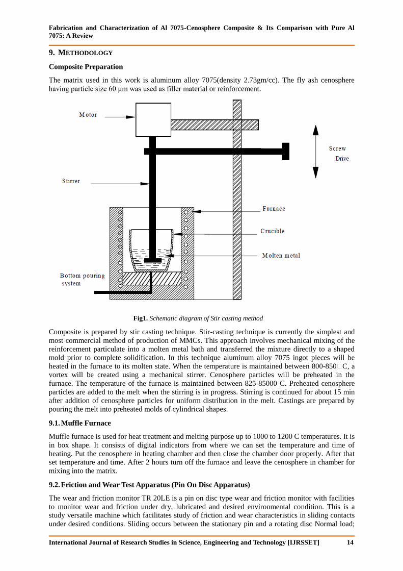
Fig1. Schematic diagram of Stir casting method
Composite is prepared by stir casting technique. Stir-casting technique is currently the simplest and
most commercial method of production of MMCs. This approach involves mechanical mixing of the
reinforcement particulate into a molten metal bath and transferred the mixture directly to a shaped
mold prior to complete solidification. In this technique aluminum alloy 7075 ingot pieces will be
heated in the furnace to its molten state. When the temperature is maintained between 800-850 C, a
vortex will be created using a mechanical stirrer. Cenosphere particles will be preheated in the
furnace. The temperature of the furnace is maintained between 825-85000 C. Preheated cenosphere
particles are added to the melt when the stirring is in progress. Stirring is continued for about 15 min
after addition of cenosphere particles for uniform distribution in the melt. Castings are prepared by
pouring the melt into preheated molds of cylindrical shapes.
9.1. Muffle Furnace
Muffle furnace is used for heat treatment and melting purpose up to 1000 to 1200 C temperatures. It is
in box shape. It consists of digital indicators from where we can set the temperature and time of
heating. Put the cenosphere in heating chamber and then close the chamber door properly. After that
set temperature and time. After 2 hours turn off the furnace and leave the cenosphere in chamber for
mixing into the matrix.
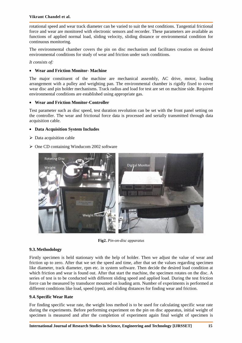
9.2. Friction and Wear Test Apparatus (Pin On Disc Apparatus)
The wear and friction monitor TR 20LE is a pin on disc type wear and friction monitor with facilities
to monitor wear and friction under dry, lubricated and desired environmental condition. This is a
study versatile machine which facilitates study of friction and wear characteristics in sliding contacts
under desired conditions. Sliding occurs between the stationary pin and a rotating disc Normal load;
Vikrant Chandel et al.
International Journal of Research Studies in Science, Engineering and Technology [IJRSSET] 15
rotational speed and wear track diameter can be varied to suit the test conditions. Tangential frictional
force and wear are monitored with electronic sensors and recorder. These parameters are available as
functions of applied normal load, sliding velocity, sliding distance or environmental condition for
continuous monitoring.
The environmental chamber covers the pin on disc mechanism and facilitates creation on desired
environmental conditions for study of wear and friction under such conditions.
It consists of:
Wear and Friction Monitor- Machine
The major constituent of the machine are mechanical assembly, AC drive, motor, loading
arrangement with a pulley and weighting pan. The environmental chamber is rigidly fixed to cover
wear disc and pin holder mechanisms. Track radius and load for test are set on machine side. Required
environmental conditions are established using appropriate gas.
Wear and Friction Monitor-Controller
Test parameter such as disc speed, test duration revolution can be set with the front panel setting on
the controller. The wear and frictional force data is processed and serially transmitted through data
acquisition cable.
Data Acquisition System Includes
Data acquisition cable
One CD containing Winducom 2002 software
Fig2. Pin-on-disc apparatus
9.3. Methodology
Firstly specimen is held stationary with the help of holder. Then we adjust the value of wear and
friction up to zero. After that we set the speed and time, after that set the values regarding specimen
like diameter, track diameter, rpm etc. in system software. Then decide the desired load condition at
which friction and wear is found out. After that start the machine, the specimen rotates on the disc. A
series of test is to be conducted with different sliding speed and applied load. During the test friction
force can be measured by transducer mounted on loading arm. Number of experiments is performed at
different conditions like load, speed (rpm), and sliding distances for finding wear and friction.
9.4. Specific Wear Rate
For finding specific wear rate, the weight loss method is to be used for calculating specific wear rate
during the experiments. Before performing experiment on the pin on disc apparatus, initial weight of
specimen is measured and after the completion of experiment again final weight of specimen is
Fabrication and Characterization of Al 7075-Cenosphere Composite & Its Comparison with Pure Al
7075: A Review
International Journal of Research Studies in Science, Engineering and Technology [IJRSSET] 16
measured. Then weight loss is finding by subtracting initial and final weight of specimen. Then
specific wear rate is found out by using following method:
KS = Δm/ ρLF (1)
Where KS is specific wear rate (mm3/Nm), Δm is the mass loss in the test duration (gm), ρ is the
density of the composite (grm/cm3) and F is the load (N), L is sliding distance (m).
9.5. Weighing Machine
Weighing machine is used to find the weight of the sample up to high fractional value. It consists of a
digital display monitor which gives the desired weight of the sample. By using this machine we can
find the volume or mass loss during sliding wear.
10. HARDNESS TESTER (ROCKWELL HARDNESS TESTING MACHINE)
Hardness test have a wide field of use although as commercial tests they are perhaps more commonly
applied to metals than to any other class of materials. The results of hardness test may be utilized as
follow
Similar materials may be graded according to hardness and a particular grade as indicated by a hardness number may be specified for some type of service.
The quality level of material or product may be checked or product may be checked or controlled by hardness test.
This hardness tester is of cast iron body. The enclosed design protects the internal operating parts from the dust effects. The elevating screw is also protected by a rubber bellow. One end of the main loading lever is located internally by two bearing and other end is free.
The diamond holder (plunger) of this machine is guided with a set of Six No bearings, with the help of which, the hardness of pins of small diameter can be tested
Test Procedure is as follows:
Keep the lever at original position.
Select the suitable indenter according to the scale.
Select the weight according to the scale and put the same on plunger of dash-pot.
Adjust initial load for Rockwell superficial and Rockwell Hardness testing respectively by turning the external knob, provided at upper right side of the machine.
Place the job on testing table.
Turn the hand wheel to raise a job, making contact with penetrator and continue turning until the long hand of the dial gauge has made two and half turns. Then it stop at 0 continue turning further till the small pointer reaches at 3. This is automatic zero setting type dial gauge and manual adjustment is not necessary. (In any case small pointer should not go beyond red spot (at 3) to avoid dial gauge damage.)
Turn the lever from position A to B so the total load will act.
When the long pointer of dial gauge reaches a steady position, take back the lever to A position slowly.
Turn the hand wheel and remove the job.
Then calculate the hardness no.
10.1. Toughness Test
The toughness is the energy requires breaking the material. The energy is calculated in jouls. The
energy consumed is calculated by the difference between total energy supplied to the energy available
at the end. The measure of toughness can be found with the help of Charpy and Izod impact tests.
10.2. Tensile Strength
The tensile test is generally performed on flat specimens. A uniaxial load is applied through both the
ends.
Vikrant Chandel et al.
International Journal of Research Studies in Science, Engineering and Technology [IJRSSET] 17
In the present work, this test is to be performed in the universal testing machine and the results are
used to calculate the tensile strength of composite samples. The test is repeated three times on each
composite type and the mean value is to be reported as the tensile strength of that composite.
10.3. Flexural Strength
The flexural strength of a composite is the maximum stress that it can withstand during bending
before reaching the breaking point. The three point bending test is conducted on all the composite
samples in the universal testing machine. For flexural strength, the test is repeated three times for each
composite type and the mean value is reported. The flexural strength of the composite specimen is
determined using the following equation:
Flexural Strength = 3PL/2bt2 (2)
Where, L is the span length of the sample (mm), P is maximum load (N), B is the width of specimen
(mm) & t is the thickness of specimen (mm)
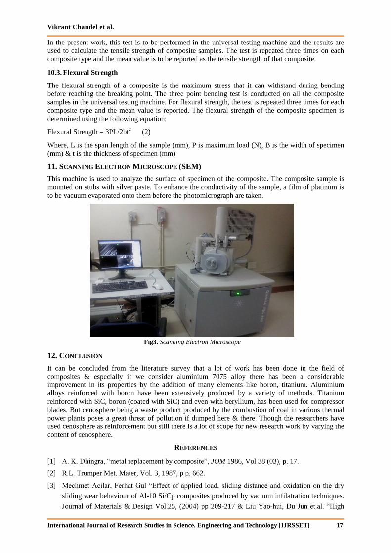
11. SCANNING ELECTRON MICROSCOPE (SEM)
This machine is used to analyze the surface of specimen of the composite. The composite sample is
mounted on stubs with silver paste. To enhance the conductivity of the sample, a film of platinum is
to be vacuum evaporated onto them before the photomicrograph are taken.
Fig3. Scanning Electron Microscope
12. CONCLUSION
It can be concluded from the literature survey that a lot of work has been done in the field of
composites & especially if we consider aluminium 7075 alloy there has been a considerable
improvement in its properties by the addition of many elements like boron, titanium. Aluminium
alloys reinforced with boron have been extensively produced by a variety of methods. Titanium
reinforced with SiC, boron (coated with SiC) and even with beryllium, has been used for compressor
blades. But cenosphere being a waste product produced by the combustion of coal in various thermal
power plants poses a great threat of pollution if dumped here & there. Though the researchers have
used cenosphere as reinforcement but still there is a lot of scope for new research work by varying the
content of cenosphere.
REFERENCES
[1] A. K. Dhingra, “metal replacement by composite”, JOM 1986, Vol 38 (03), p. 17.
[2] R.L. Trumper Met. Mater, Vol. 3, 1987, p p. 662.
[3] Mechmet Acilar, Ferhat Gul “Effect of applied load, sliding distance and oxidation on the dry
sliding wear behaviour of Al-10 Si/Cp composites produced by vacuum infilatration techniques.
Journal of Materials & Design Vol.25, (2004) pp 209-217 & Liu Yao-hui, Du Jun et.al. “High
Fabrication and Characterization of Al 7075-Cenosphere Composite & Its Comparison with Pure Al
7075: A Review
International Journal of Research Studies in Science, Engineering and Technology [IJRSSET] 18
temperature friction and Wear behaviour of Al2O3 and /or Carbon short fibre reinforced Al-1 Si
alloy omposites” Wear 56, 004, pp 75-285.
[4] A.Alahelisten, F.Bergman, M.Olsson, S.Hogmark, “on the wear of aluminum and magnesium
metal matrix composites”, Wear Vol.165, 1993, pp 1-226.
[5] J.Q.Jiang, R.S.Tan, A.B.Ma, “Dry sliding wear behaviour of Al2O3-Al composite produced by
centrifugal force infiltration”, Material Science and Technology, Vol. 1, 1996, pp 483-488.
[6] P.N.Bindhumadhan, H.K.Wah, O.Prabhakar, “Dual particle size (DPS) composites: effect on
wear and mechanical properties of particulate matrix composites” Wear, Vol. 48, 2001, pp 112-
120.
[7] S. Tjong, S.Q. Wu, and H. Liao: “Wear behavior of an Al–12% Si alloy reinforced with a low
volume fraction of Si particles.” Journal of composite science and technology, Vol–57, Issue–12,
Dec 1997, pp 1551-1558.
[8] S. Tjong, H.Z.Wang and S.Q.Wu “Wear Behavior of Aluminum based Metal Matrix Composites
Reinforced with a Perform of Aluminosilicate Fiber” Metallurgical and Materials Transactions
A, Vol 27A, (1996) 2385-2389.
[9] M.Singh, D.P.Mondal et.al. “Development of light weight aluminum alloy hard particle
composite using natural minerals for wear resistance application. National conventions on
emerging materials on wear applications. paper no TS- 4/5, 2003, Bhopal.
[10] Ferdinand A.A. & Gregoire R.R., Fr1, 157, 477 May 29, 1958, Chem. Abstr. 1960, 54, 19430e.
[11] Elmer P., Freiberger Forschungsh, B67 117 – 30 (1962); Chem. Abstr. 1962, 57, 12166a.
[12] Thakur R.S. & Sant B.R., J.Sc.Ind.Res.1974; 33(8), 408-16, Chem. Abstr. 1975, 82, 159934x.
[13] Harvath G. & Illyes J., Banyasz Kohasz Lopak, Kohasz (1975); Chem. Abstr. 1975, 83,
196543k.
[14] Thakur R.S, Muralidhar J. & Sant B.R., Chem Age of India, 1977, 28(2), pp39-40.
[15] Aggarwal P.S, Lele R.V. & Sen. S.K., Chem Age of India 1977; 28(2), pp.114-115,
Chem.Abstr.1977, 86,175729x.
[16] Grigoreva .D., Volfson G.I., Malts N.S. & Shmorgunenko N.S., Tsvetn.Met, 1977;(7) 34-5,
Chem. Abstr. 1977, 87, 155285s.
[17] Kudinov B.Z., Bychin A.I., Leontev L.I., Kiselev V.A. & Drug_alev S.M., Deposited Doc.
VINITI 1306-77, 1977, p 11 Chem.abstr.1979, 90, 74885x.
[18] Pustilnik G.L., “Komplekon. Ispolz. Syrevykh Resur Predpr. Tsvetn. Metall” 1974, Pub 1977
248-74: Edited by Adbekyan A.kh. Isz‟ Aiastin‟ Yerevan; hem.Abstr. 1979, 91, 195223j.
[19] Zamb J., Trav.Com. Int. Etude Bauxites Alumine Alum, 1979; 15, pp.265-277, Chem.Abstr.
1980, 93, 117887f.
[20] Nikolaev, I. V. TsvetnMet 1983; (6) 61-3, Chem. Abstr.1983, 99,73009p.
[21] Stanescu N., MinePet.Gaze.1990, 41(5) 222-4; Chem.Abstr.1991, 114,86023s.
[22] R. Mehrabian, R.G. Riek and M. . Flemings, “preparation and casting of Metal-Particulate Non-
Metal omposites,” Metall. Trans, Vol. 5A, 1974, pp 1899-1905.
[23] J. Eliasson and R. Sandstorm, “Applications of Aluminium Matrix omposites,” Part 1, G. M.
Newaz, H. Neber-Aeschbacherand F. H. Wohlbier eds., Trans. Tech. publications, Switzerland,
1995, pp 3-36.
Vikrant Chandel et al.
International Journal of Research Studies in Science, Engineering and Technology [IJRSSET] 19
[24] John E. Allison, Gerald S. ole, “Metal Matrix omposites on the automotive Industry:
Opportunities and hallenges”, JOM, Vol. 45(1), 1993, pp 19-24.
[25] D. J. Lloyd, “Particulate Reinforced omposites Produced by Molten mixing,” High Performance
omposites for the 1990‟s, eds. S.K.Das, .P. Ballard and F.Marikar, TMS-New Jersey, 1990, pp
33-46.
[26] M.G. McKimpson and T.E.Scott, “Processing and Properties of MM s ontaining Discontinuous
Reinforcement”, Mat. Sci. and Engg, Vol. 107A, 1989, pp 93-106.
[27] H.J. Rack, “Metal Matrix omposites”, Adv. Mater. Processes, Vol. 137 (1), 1990, pp 37-39.
[28] A. W. Urquhart, “Molten Metals Sire MM s, M s”, Adv. Mater. Processes, Vol. 140(7), 1991, pp
25-29.
[29] V. V. Bhanuprasad, K. S. Prasad, A.K. Kuruvilla, A. B. Pandey, B. V. R. Bhat and Y. R.
Mahajan, “ Composite Strengthening in 6061 and Al-4Mg Alloys”, . at. Sci. Vol. 26, 1991, pp
460-466.
[30] M. S. Zedias, P. S. Gilman and S.K.Das, “High Temperature Discontinuously Reinforced
Aluminium”, JOM, Vol. 43(8), 1991, pp 9-31.
[31] R. A. Higgins, “Properties of Engg. Materials”, Holder & Stoughton , 1986.
[32] M. S. Zedias, P. S. Gilman and S.K.Das, “ High Temperature Aluminium-Base omposites”, High
performance omposites for the 1990‟s eds. S. K. Das, .P.Ballard and F. Marikar, Tms-Newjersey,
1990, pp 61-82.
[33] .P. You, A.W. Thompson and I. M. Bernstein, “Proposed Failure Mechanism in a
Discontinuously Reinforced Aluminium Alloy”, Scr. Metall., Vol. 1, 1987, pp 181-185.
[34] T. W. Clyne and J. F. Mason, “ the squeeze Infiltration process for Fabrication of MM s”, Metall.
Trans., Vol. 18A, 1987, pp 1519-1530.
[35] M. Gupta, I.A. Ibrahim, F. A. Mohamed, E. J. lavernia, “Wetting and Interfacial Reactions in Al-
Li-SiCp MMCs Processed by spray Atomozation and Deposition”, J. Mat. Sci. Vol. 26, 1991, pp
6673-6684.
[36] D.Z. Yang, S. L. Dong, J. F. Mao and Y. X. ui, “Fabrication Microstructure and Properties of A
SiCw/ Al-Li-Cu-Mg-Zr omposite”, Key Engineering Materials, Vol.s104-107, Metal Matrix
Composites, Part 1, G. M. Newaz, H. Neber-Aeschbacher and F. H. Wohlber eds., Trans. Tech.
Publications, Switzerland, 1995, pp 627-632.
[37] D.J. Lloyd, “The Solidification Microstructure of Particulate Reinforced Al/Si omposites”,
Comp. Sci. Tech., Vol. 35, 1989, pp 159-179.
[38] D harles, “Addressing the hallenges of Aircraft omponents design and Manufacturing from MM
s”, J. Aerospace Engg (Proc. I. Mech E) pp 1-13, 1992.
[39] Michael E. Buck, “Addressing fibers from Advanced omposites”, Advanced Materials and
Processes, pp 61-68, Sept 1987.
[40] Alan, L.Geigr and Michael Jackson, “Low-Expansion MM s Boost Avionics”, Advanced
Materials and Processes”, pp 3-32, July 1989.
[41] Herbert Dietrich, “Carbon/ Carbon, Protected / Protedted”, Mater. Engg. Vol. 108(8), 1991, pp
34-35.
[42] T.S. hester, “Non-metallic Materials for Gas Turbine Engines: Are They Real?” Adv. Mater.
Processes, Vol. 139(6), 1991, pp 32-39.
Fabrication and Characterization of Al 7075-Cenosphere Composite & Its Comparison with Pure Al
7075: A Review
International Journal of Research Studies in Science, Engineering and Technology [IJRSSET] 20
[43] M.V. Roode, J. R. Price and. Stala, “ceramic Oxide oatings for the orrosion Protection of Si”, J.
Engg. Gas Turbines Power Trans. ASME, Vol. 115(1), 1993, pp 139-149.
[44] D. Huda, M.A. El Baradie & M.J.S. Hashmi, “Metal Matrix omposites: Materials aspects. Part
II” Journal of material processing technology, Vol.37 (1993), 58-541.
[45] Alok Satapathy & S. Mishra “Plasma Spray oating of Red Mud on Metal” Proceeding of DAE-
BRNS, International Symposium on Applications of Power Beams in Advanced Material
Processing, BARC, Mumbai, 2002, pp.709-712.
[46] E. Hunt, P.D. Pitcher and P. J. Gregson, “Advanced Al and Mg Alloys”, T. Khan and G.
Effenberg eds., ASM.
[47] D. H. Kim, E.J. Lavernia and J. . Earthman, “ Fatigue rack growth behaviour of a continuous
alumina fiber reinforced Magnesium alloy”, High performance omposites for the 1990‟s eds.
S.K. Das, . P. Ballard and F. Marikar, TMS-New Jersey, 1990, pp 117-126.
[48] P.J. Meachter and J.E. Oneil, “Communication: Rapid Solidification Processing of Magnesium-
Lithium Alloys”, Metall. Trans., Vol. 15A, 1984, pp 37-240.
[49] J.E. Hack, R. E. Page and G.R. Leverant, “Tensile and Fatigue Behaviour of Aluminium Oxide
Fiber Reinforced Magnesium omposites: part I. Fiber Fraction and Orientation”, Metall. Trans.,
Vol. 15A, 1984, pp 1389-1396.
[50] N.Eustathopoulos, D. hatain and L. oudurier, “Wetting and Interfacial hemistry in Liquid Metal
eramic Systems”, Mat.Sci and Engg. Vol.135A, 1991, pp 83-88.
[51] M. Taya & R.J.Arsenault, “Metal Matrix omposite thermo mechanical behavior”, Pergamon
press, 1989.
[52] R.J.Arsenault, „The Strengthening of Al Alloy 6061 by Fiber and Platelet Silicon arbide,‟ Mat.
Sci. Engg., Vol. 64, 1984, pp171-181.
[53] Kassim S. Al-Rubaie, Humberto N. Yoshimura, Jose´ Daniel Biasoli de Mello, “Two-body
abrasive wear of Al–SiC composites”, Wear 233–235 _1999. 444–454.
[54] ROHATGI, P.K (2006):- “Applications of fly ash in synthesizing low cost Metal Matrix
Composites for automotive and other engineering applications”, JOM, vol. 58, issue no.11,
pp.71-76,2006.
[55] RAO, J.BABU (2010):- “Development of light weight ALFA composites”, interntional journal
of engineering, science and technology. Vol.2, issue no.11, pp. 50-59, 2010.
[56] SHANMUGHASUNDARAM, P. (2011):- “Some studies on Aluminium- Fly Ash composites
fabricated by two step stir casting method”, European journal of scientific research, vol. 63, issue
no.2, pp. 204-218, 2011.
[57] V. Constantin, L. Scheed & J. Masounave, “Sliding Wear of Aluminum- Silicon Carbide Metal
Matrix Composites” Journal of Tribology, ASME, 1999.
[58] D. L. McOanels and R. A. Signorelli, “Evaluation of Low-Cost Aluminum Composites for
Aircraft Engine Structural Applications” Metallurgical Society of the American Institute of
Mining, Metallurgical and Petroleum Engineers Atlanta Georgia, March 6-10, 1983.