Embed Size (px)
Citation preview

Fabrication and Characterization of a Silk-HA
Based Scaffold for Multi-compartmental B-L-B
Graft
A THESIS SUBMITTED FOR PARTIAL FULFILLMENT OF THE REQUIREMENT FOR
THE DEGREE OF
BACHELOR OF TECHNOLOGY
IN
BIOMEDICAL ENGINEERING
By:
SASMITA MAJHI
(Roll no. 109BM0009)
Under the guidance of:
Dr. BIBHUKALYAN PRASAD NAYAK
Department Of Biotechnology And Medical Engineering
National Institute Of Technology Rourkela
2013

i
National Institute of Technology, Rourkela
Certificate This is to certify that the report entitled, “Fabrication and Characterization of a
Silk-HA Based Scaffold for Multi-compartmental B-L-B Graft”, submitted by Miss.
Sasmita Majhi, Roll no.: 109BM0009, B.Tech-8th semester, Department of Biotechnology
& Medical Engineering, National Institute of Technology, Rourkela (Deemed University) is
an authentic work carried out by her under my supervision and guidance.
To the best of my knowledge, the matter embodied in the report has not been
submitted to any other University / Institute for the award of any Degree or Diploma.
Date: Dr. B. P. NAYAK
Department of Biotechnology & Medical Engineering
National Institute of Technology
Rourkela – 769008

ii
ACKNOWLEDGEMENT
I would like to express express my deep sense of gratitude and heartfelt thanks to Dr.
Bibhukalyan Prasad, Department of Biotechnology and Medical Engineering, NIT
Rourkela, for his esteem guidance and noble supervision throughout my project.
I extend my sincere thanks to Prof G.S Hotta, Department of Chemistry, NIT
Rourkela for allowing me to use the lab facilities. My special thanks to research scholar Ms.
Abhipsa Mahapatra and Ms.Shabna patel. I would like to thank Mr.Aadeshkumar
Shendge, Mr. Akshaya Kumar Padhi , Mr. Patitapabana Parida, who helped me to solve
many problems of my work.
I would like to express my heartily thanks to my friends Rachna Mund, Ankita
Sarangi, lab mates and others in the department for their help and support.
Finally, I would like to express my heartfelt thanks to my parents, my brother and all
my family members, for their blessings, support, and for constant encouragement and very
special thanks to God for showering the blessings on me.
Sasmita Majhi

iii
TABLE OF CONTENTS
ACKNOWLEDGEMENT ii
LIST OF FIGURES v
LIST OF TABLES vii
ABSTRACT viii
Chapter Topic Page No.
CHAPTER 1 INTRODUCTION
Introduction 2
CHAPTER 2 LITERATURE REVIEW
2.1 Musculoskeletal system 4
2.1.1 Soft tissue 4
2.1.2 Enthesis Composition and Structural
Organization 4
2.2 Properties of tissue Soft tissue 5
2.2.1 Mechanical Property of Load Bearing Tissue 5
2.2.2 Properties of Hard tissue 6
2.3 Tissue engineering & organogenesis 7
2.3.1 Biomaterial and Scaffold 8
2.3.2 Cells 8
2.3.3 Growth Factor 9
2.3.4 Bioreactor 9
2.4 Bone 10
2.4.1 Cells for Bone Tissue Engineering 11
2.4.2 Growth Factors 12
2.4.3 Bioreactors 12
CHAPTER 3 MATERIALS AND METHODS
3.1 Procurement of degummed silk 14
3.2 Knitting of silk fibre 14
3.2.1 Morphological characterization of knitted
scaffold
15
3.2.2 Determination of Porosity of knitted Scaffold 16

iv
3.2.3 Mechanical testing of knitted scaffolds 16
3.3 Biodegradability test 16
3.3.1 Mechanical testing of degraded scaffolds 17
3.4 Scaffold Fabrication 17
3.4.1 Preparation of HA/PCL Solution 17
3.4.2 Electrospinning 17
3.4.3 Morphological characterization of
Electrospinned fibers 18
3.5 FTIR Analysis 18
3.5.1 FTIR analysis of knitted fabricated HA/PCL
scaffold 19
3.6 Cell culture 19
3.6.1 Preparation of DMEM 20
3.6.2 Sub-culturing of cells 20
3.7 Cell Seeding 20
3.7.1 Mechanical testing of cell seeded scaffold 20
3.7.2 Cell viability test 21
3.7.3 Cell proliferation test 21
CHAPTER 4 RESULTS AND DISCUSSIONS 23
CHAPTER 5 CONCLUSION AND FUTURE WORK 30
CHAPTER 6 REFERENCES 32

v
LIST OF FIGURES
Figure No. Description Page No.
Figure 2.1 Load-elongation and load-time diagram 5
Figure 2.2 Viscoelastic behaviour of living tissue 6
Figure 2.3 Mechanical properties of mineralised tissue 7
Figure 2.4 Tissue growth in bioreactor 8
Figure 3.1 Degummed silk 14
Figure 3.2 Knitting machine 14
Figure 3.3 Knitted silk scaffold 15
Figure 3.4. TA-HDPlus Texture Analyser 16
Figure 3.5 Scaffolds in PBS medium 17
Figure 3.6 Electrospining setup used in experiment 18
Figure 3.7 FTIR Spectroscope 19
Figure 3.8 Cultured fibroblast (L929 cells) 19
Figure 4.1 SEM image of Knitted Sik scaffold 23
Figure 4.2 Data plotted for degradation study of knitted scaffold in PBS 24
Figure 4.3 SEM image of electrospinned HA:PCL of 1:1 ratio. 24
Figure 4.4 SEM image of electrospinned HA:PCL fibre on knitted silk
Scaffold
25
Figure 4.5 Plot between % of transmittance vs wavenumbers for 1:1 ratio
of HA: PCL. 25
Figure 4.6 Plot between % of transmittance vs wavenumbers for 0.05:1 26

vi
ratio of HA: PCL
Figure 4.7 Comparative FTIR study of HA-PCL in different concentration,
(a) 1:1 ratio of HA: PCL (b) 0.05:1 ratio of HA: PCL 26
Figure 4.8 Microscopic view of cultured adherent fibroblast (L929) cells. 27
Figure 4.9 The absorption rate result of MTT assay for fibroblast cell in 24
hrs. 28

vii
LIST OF TABLES
Table No. Description Page No.
Table 4.1 Mechanical strength of scaffolds soaked in PBS 23
Table 4.2 Mechanical Strength for seeded scaffold 28

viii
ABSTRACT
Tissue engineering being a central forum for ground breaking scientific research and
developments in biomedical applications caters to design and fabrication of new tissues by
development of biodegradable substitutes for functional restoration & regeneration of
impaired organs. The key to success in tissue engineering is customized and precisely
optimized scaffolds specific to the tissue type. With the highest demand in musculoskeletal
tissue engineering, it’s a challenge to construct a complex scaffold for incorporating interface
organ to bridge ligament/tendon with bone to replace injured ligaments beyond repair. Such a
scaffold must act as a template for tissue formation providing a 3D platform to the seeded
cells in addition to providing enough mechanical strength required at soft to hard tissue
interface to construct a Bone-Ligament-Bone graft. In the current project, a scaffold for bone
compartment of a multi-compartmental B-L-B graft was fabricated by knitting silk fibroin as
core material to impart mechanical strength. Hydroxyapatite (HA) being known for its
osteoconductive and osteoinductive properties, was integrated on the surface of silk fibroins
by electrospinning along with the biodegradable polymer, PCL(Poly caprolactone). The
fabricated scaffold was characterized for mechanical properties like biodegradability,
stiffness, porosity in addition to biocompatibility features like cell adhesion efficiency, cell
proliferation after seeding fibroblasts. The nano-microscaffold showed the capability to
support growth and proliferation of seeded fibroblast cells and an average yield stress of
38±0.18 kg/cm2. It was concluded that the fabricated scaffold can be effectively used for
bone tissue engineering that needs further confirmation using bone cells.
Keywords: Silk, Scaffold, Knitting, Electrospinning, Hydroxyapatite, PCL, Fibroblast.

1
CHAPTER -1
INTRODUCTION

2
1. Introduction
Recently a new process to create a hard tissue (bone)-soft tissue (cartilage or
ligament) bilayered scaffold was developed. Because of sports-related injuries and aging
population musculoskeletal disorders have been converted into one of the major health
concerns. Bone repair typically involves the use of allografts or autografts, ligament repair
often uses patellar tendon, whereas cartilage repair requires use of cartilaginous grafts or joint
resurfacing. In most cases of musculoskeletal disorder, total joint replacements are done
using prosthetics. Because of insufficient supply of donor tissue, this technique cannot always
be practical. As well as obtaining tissue from other source poses the risk of immunorejection
and disease transfer. Tissue engineering may be a way to evade the limitations of existing
therapies by applying the principles of engineering and biology in solving the problems
associated with partial or whole organ transplantation. One of the approach is to use three-
dimensional porous, biodegradable polymeric scaffolds, which provides support for the in
growth of new tissue as the scaffold degrades devices have been used. Yet another approach
is to culture the cells on a preformed three-dimensional scaffold and transplant the cell-
polymer construct into the patient.
Electrospinning is considered to be one of the most promising processes in the field of
nanotechnology due to its simplicity, low cost, high productivity, reproducibility and its
potential to be scaled up to the industrial scale .The method involves the application of a high
voltage electric field to draw very thin fibres from a polymeric fluid stream (solution or melt)
delivered through a millimeter-scale nozzle. Electrospinning technique depends on various
processing parameters such as solution properties (e.g., viscosity, surface tension and
conductivity) and processing parameters (e.g., electric field strength, solution flow rate,
needle diameter and distance between needle tip and ground collector).
Nano fiber is defined as the fiber having at least one dimension in nanometer range.
Nano fiber is used for a wide range of medical applications for drug delivery systems,
scaffold formation, wound healing and widely used in tissue engineering, skeletal tissue,
bone tissue, cartilage tissue, neural tissue ,ligament tissue, etc.

3
CHAPTER -2
LITERATURE REVIEW

4
2. Literature Review
2.1 Musculoskeletal system
2.1.1 Soft tissue
During embryogenesis, gastrulation occurs in the 3rdweek of development. This process
establishes all three germ layers in the embryo. The ectodermal layer gives rise to organs and
structures that are in contact with the outer world, e.g.; central and peripheral nervous system,
sensory epithelium, epidermis, and mammary gland (1). The mesodermal layer forms the
dermis and subcutaneous layers of the skin, connective tissue, cartilage, bone, muscle, blood
cells, and endothelium. Regarding the ECM in developing tissues, two major alterations
occur: the components of the ECM change, and the cellular reactivity to the ECM
components change. The ECM and cell surfaces interact functionally and this plays an
intense role in the development and maintenance of a number of cells and tissues. Hence, the
ECM is also instructive, or informational, and greatly influences cell behaviour. ECM is
mainly composed of collagen, glycoproteins and proteoglycans,. Different ECMs contain
different elements which define their tissue specificity (2).
2.1.2 Enthesis Composition and Structural Organization
An enthesis is the specialized arrangement of connective tissue that comprises the
attachment of a muscle to a bone while permitting the muscle’s fibres to be organised in
appropriate pennation. An enthesis may be categorised into a fibrous enthesis or a fibro-
cartilaginous according to (Benjamin et al.) based on the characteristics of the tissue at the
bone-tendon interface location. A fibrous enthesis is composed with mainly dense fibrous
connective tissues and can be further divided into two categories – periosteal and bony,
depending on the region to which the tendon attaches. On the other hand, a fibro-
cartilaginous enthesis appears in the area which is subject to compression and shows two
more additional zones between connective tissue and bone – uncalcified fibrocartilage and
calcified fibrocartilage. Entheses are mostly the sites of musculoskeletal overuse injuries that
include tennis elbow and jumper’s knee.
5
2.2 Properties of Soft tissue
Soft biological tissues mostly encounter high range of diversity in its mechanical properties.
These organic tissues are generally characterized by complex mechanical behaviour. They
used to show non-linear, viscoelastic, and anisotropic behaviour. They often have a layered or
complicated structure. Inhomogenity in mechanical properties is due to varied positions in
material. The perfusion of the organs and their constituting tissues are important while
regarding the elastic properties.
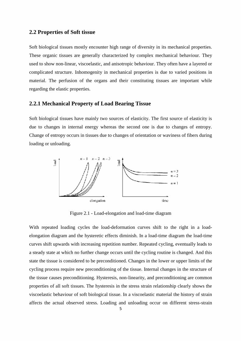
2.2.1 Mechanical Property of Load Bearing Tissue
Soft biological tissues have mainly two sources of elasticity. The first source of elasticity is
due to changes in internal energy whereas the second one is due to changes of entropy.
Change of entropy occurs in tissues due to changes of orientation or waviness of fibers during
loading or unloading.
Figure 2.1 - Load-elongation and load-time diagram
With repeated loading cycles the load-deformation curves shift to the right in a load-
elongation diagram and the hysteretic effects diminish. In a load-time diagram the load-time
curves shift upwards with increasing repetition number. Repeated cycling, eventually leads to
a steady state at which no further change occurs until the cycling routine is changed. And this
state the tissue is considered to be preconditioned. Changes in the lower or upper limits of the
cycling process require new preconditioning of the tissue. Internal changes in the structure of
the tissue causes preconditioning. Hysteresis, non-linearity, and preconditioning are common
properties of all soft tissues. The hysteresis in the stress strain relationship clearly shows the
viscoelastic behaviour of soft biological tissue. In a viscoelastic material the history of strain
affects the actual observed stress. Loading and unloading occur on different stress-strain

6
paths leading to hysteresis. The hysteresis of most biological tissues is assumed to show only
little dependence on the strain rate within several decades of strain rate variation. This
insensitivity in strain rate over several decades is not compatible with simple viscoelastic
models like: single spring and dashpot element. For such simple viscoelasticity approach the
material model will show a maximum hysteresis loop at a certain strain rate whereas all other
strain rates will show a smaller hysteresis loop. A model having a discrete number of spring-
dashpot elements produces a discrete hysteresis spectrum with maximum dissipation at
discrete strain rates. By choosing the relaxation times of the different elements adequately a
series of spring-dashpot elements might be used as an approximation to a continuous
relaxation spectrum. Living tissues often show viscoelastic behaviour as shown qualitatively
in the figure below.
Figure 2.2 - Viscoelastic behaviour of living tissue
In the above figure the viscoelastic material properties are characterized by storage modulus
and loss modulus. With a series of spring-dashpot elements arbitrary viscoelastic material
properties can be modelled.
2.2.2 Properties of Hard tissue
In bone, the main determinant of mechanical properties is the amount of mineral in the tissue.
Presence of more mineral displaces water making the bone becomes stiffer, but at the same
time becomes more brittle.

7
Figure 2.3 - Mechanical properties of mineralised tissue
Fig. shows the relationship between the stiffness (Young’s modulus) of bone and its bending
strength. These values come from bone specimens from a wide variety of amniote species,
each point representing the value for a single specimen. Apart from the specimens labelled
‘A’, there is clearly a very strong, almost linear, relationship between Young’s modulus and
strength, with the strength values being approximately 1/100 of the stiffness values.In 1991,
Currey et al. demonstrated that the failure of bone in bending is determined by the strain to
which it is subjected. This relationship seems to be true whether differences in modulus are
determined by differences in mineralisation and/or by differences in porosity. That is to say,
it is the strain in the outermost fibres of a specimen that will determine whether a specimen
breaks when subjected to a particular bending moment, no matter what causes it to have these
high strains.
2.3 Tissue engineering & organogenesis
The basic concept of tissue engineering includes a scaffold that provides a architecture on
which seeded cells can organize and develop into the desired organ or tissue prior to
implantation. The scaffold provides an early biomechanical contour for the replacement
tissue until the cells produce an adequate amount of extracellular matrix. During the
formation and deposition of the new matrices, the scaffold is degraded eventually leaving a
vital organ or tissue that restores, maintains, or improves tissue function(11).

8
Figure 2.4 - Tissue growth in bioreactor
Biomaterials, cell sources, growth factors for cell and bioreactors are four components for
tissue engineering. In this part, these four components are reviewed for tendon and ligament
tissue engineering.
2.3.1 Biomaterial and Scaffold
There are several requirements govern the choice of materials for tendon and ligament tissue
engineering. Firstly, the material must be non-toxic and biocompatible (12). The material
must not cause abnormal responses in local tissues surrounding the implant and should not
produce toxic or carcinogenic effects. Secondly, the material should avoid infection, so that
the material should be sterile-able before seeding the cells onto the scaffold, and should stay
sterile prior to implantation. The sterilization technique should not alter the mechanical and
physical properties of the material. Finally, the scaffold material should provide some
mechanical integrity initially to replace the function of the lost tendon or ligament before the
scaffold degrades and is replaced with new extracellular matrix. Tendon and ligament have
extremely hierarchal organized collagen structure, hence the requirement of the scaffolds for
tendon and ligament repair is that the scaffolds need the similar micro and macro morphology
as tendon and ligament.
2.3.2 Cells
Fibroblast: There are two types of tendon fibroblast cells in tendon, tenocytes and tenoblasts.
And fibroblast is major cell type in ligament. Some studies have been done using fibroblasts
for tendon and ligament repair in animal models (13).

9
Stem cells: Stem cells are very attractive cell sources for tendon tissue engineering. Stem
cells are undifferentiated cells and have the ability to self-renew and differentiate to one or
more types of specialized cells. Stem cells can be classed to two types: embryonic stem (ES)
cells and adult stem cells. Sources of ES cells: blastocysts and fetal tissue. These have got
importance in the field of tissue engineering and regenerative medicine because they have the
potential to produce most types of cells in the body (14). Although the potential of ES cells in
tissue engineering is vast, there are many problems must be overcome. For example, human
ES cells may be contaminated by animal cells or proteins. It is reported that nonhuman
protein expressed by human ES cell lines grown on animal feeder layers (15). Other problems
such as immunorejection and tumorigenesis are also obstacles for the clinical applications of
ES cells.
2.3.3 Growth Factor
Growth and differentiation of ligament and tendons tissue are influenced by various growth
factors: basic fibroblast growth factor (bFGF), platelet-derived growth factor (PDGF),
epidermal growth factor (EGF), insulin-like growth factor (IGF)-1, and members of the
family of TGF-β/bone morphogenetic proteins (TGF-β/BMPs).
2.3.4 Bioreactor
Bioreactors are essential for meeting the complex requirements of in vitro engineering of
functional skeletal tissues. Cell proliferation and collagen synthesis is reported for chicken
tendon cultured in vitro, undergoing cyclic tension for 14 days. Two major strategies may be
applied for tendon tissue engineering. One is the in vivo approach of tendon engineering
involving in situ delivery of cells, biomolecules, hydrogels or scaffolds to boost the
regeneration and healing process to deal with the repair of small defects and the induction of
tissue self-regeneration(16) .The other is the in vitro tissue engineering involving the growth
of tendon-like tissue structure outside of the body and the implantation into the defect. This
strategy is more concerned with larger defects or tissue replacement.

10
2.4 Bone
Bone is a dynamic, highly vascularised tissue having the unique capacity to heal and remodel
injuries as well as its capacity to rapidly mobilize mineral stores, formulate it as the ultimate
smart material. Its main function is to provide structural support for the body. The selection
of the most appropriate material to produce a scaffold to be used in bone tissue engineering
applications is a very important step towards the construction of a tissue engineered product,
since its properties will determine, to a great extent, the properties of the scaffold (16).They
can be from natural (e.g., coralline hydroxylapatite (HA)) origin or synthetic such as
synthetic HA or β-tricalcium phosphate (β-TCP).Because of their fascinating properties,
osteoconductivity and osteoinductivity, they have been considered for bone tissue
engineering. Several works have revealed good results concerning bone regeneration by using
ceramics with or without bone marrow cells. In 2001,R.Quarto et al. encompassed major
drawbacks of these materials.
To begin with they are brittle and present a low mechanical stability, which prevents
their use in the regeneration of large bone defects. Because of osteoclastic activity, their
degradation rates are difficult to expect. This could prove a problem because if it degrades
too fast it will compromise the mechanical stability of the construct, which is low by itself. At
the same time, this would dramatically lead to as .In 2001,C.S.Adams et al., verified that
increment in the extracellular concentrations of Ca and P, can cause cellular death. There are
also alternative biodegradable polymers, which are supposed to be the ideal materials for
bone tissue engineering. These can be divided in two groups: natural and synthetic.
Natural biodegradable polymers are those obtained from natural sources.These
include: collagen, fibrinogen, chitosan, starch, hyaluronic acid (HA), and poly
(hydroxybutyrate). The main advantages of these materials are their potential for low
immunogenic response, their impending bioactive behavior and the capability of interacting
with the host’s tissues. Synthetic biodegradable polymers are generally used in biomedical
engineering field. As the processability and chemical versatility of those polymers varies
according to their structure and nature, and hence a direct relation cannot be established with
the natural polymers. The most widely used are poly (α-hydroxyacids), poly(e-caprolactone),
poly(propylenefumarates), poly(carbonates), poly-(phosphazenes),and poly(anhydrides).

11
2.4.1 Cells for Bone Tissue Engineering
Osteoblasts
Osteoblasts are generally isolated from biopsies taken from the patients (autologous),
followed by limited expansion in vitro because of their non-immunogenicity. However this
method has got several limitations: it takes a lot of time, comparatively few cells are available
after the dissociation of the tissue and their spreading out rates are relatively low, restricting
the number of cells to be seeded on the scaffolds. And in certain bone related diseases
osteoblasts may not be appropriate for transplantation as their protein expression profile is
under the expected values (18).
Embryonic Stem Cells
ES cells inhabit in the inner cell mass of the blastocyst. Later on it was found that after being
transferred to early mouse embryos ES cells could give rise to all somatic cell types of the
embryo, including the germ line(20).Up to now it was reported the isolation of ES cells from
rodents primates and human beings.
Adult Stem Cells
Adult stem cells (ASCs) reside in the fully differentiated or adult tissues. ASCs were found in
the bone marrow, periosteum, muscle, fat, brain, and skin. In the bone tissue engineering field
there has been a special interest in the stem cells located in the bone marrow, known as
Mesenchymal Stem Cells (MSC). The idea that bone marrow contained some kind of
osteogenic precursor cells started in 1963, showed that by implanting pieces of bone marrow
beneath the renal capsule, it was possible to acquire an osseous tissue. After this Friedenstein
and co-workers revealed a series of in vivo studies in which it was shown the possible
existence of osteogenic stem cells in the bone marrow.In 1968,A.J.Friedenstein et al.,
developed a method to isolate fibroblast-like cells from the marrow to understand the nature
and source of these cells. Later he coined the term colony-forming units fibroblastic (CFU-F)
to describe these cells that were fibroblastic, non-phagocytic and clonogenic in nature.

12
2.4.2 Growth Factors
Like other tissues bone tissue also possess a surplus of growth factors.These includes: bone
morphogenetic proteins (BMPs), transforming growth factor beta (TGFb), fibroblast growth
factors (FGFs), insulin growth factor I and II (IGF I/II), and platelet derived growth factor
(PDGF) are the most common and those that have realistically been proposed for bone tissue
engineering applications(21).
2.4.3 Bioreactors
Bone is considered as highly structured mechanically active 3D tissue. The biological
environment of osteoblasts is thus derived from a dynamic interaction between active cells
experiencing mechanical forces and a continuously changing 3D matrix architecture(22). In
order to develop tissue engineered products in vitro it is thus needed to develop adequate
cell/scaffold culture systems that mimic the dynamics of the in vivo environment. Till date
two systems have been normally used, spinner flasks and rotating wall vessel reactors
(RWVR).

13
CHAPTER -3
MATERIALS
AND
METHODS

14
3. Materials and Methods
3.1 Procurement of degummed silk
Degummed silk fibres (Tasar) were procured from Central tasar research and training
institute, Central silk board Jharkhand, INDIA).
Figure 3.1 - Degummed silk
Figure 3.2 - Knitting machine
3.2 Knitting of silk fibre
Silk fibres were wound into yarns. Yarns were made into varied turns (3, 5, 8, 12). Scaffolds
were prepared from all respective turns of silk. According to instructions in manual the
tension in the machine was adjusted between 0-4 to carry out the knitting with desired pore

15
size. The steps were followed to arrange the fibre in the machine for knitting. Scaffolds
dimension were adjusted to (5cm*2cm).Hence the required needles (9 nos.) were used. To
start with knitting the fibre bundle was kept perpendicular under K-Carriage arm. During
knitting the pressure was maintained through out to avoid any knot in scaffolds or loosening
during preparation. The scaffold was given tension using clip to keep it elongated during
knitting. Scaffolds were then arranged inside metal strips to keep them stretched.
Figure 3.3 - Knitted silk scaffold
3.2.1 Morphological characterization of knitted scaffold
Scanning Electron Microscopy (SEM) Analysis:
The morphology and structure of the knitted fibres can be analyzed under optical scanning
electron microscope. A JEOL JSM- 6480LV SEM was used in the experiment for
characterization of fibres at an accelerating voltage of 15 KV. Scaffold samples were cut into
small pieces with the help of scissor. Small scaffolds were mounted with the help of carbon
tape on the sample holder. Each sample was then coated with a thick layer of platinum by a
JEOL JFC -1600 auto fine coater .And the operating conditions were maintained at 20 mA
for 90 seconds.

16
3.2.2 Determination of Porosity of knitted Scaffold
The pore size was obtained from SEM images of knitted scaffold using the Image J program.
3.2.3 Mechanical testing of knitted scaffolds
Tensile strength of scaffold was tested using TA-HDPlus Texture Analyser.
Figure 3.4 - TA-HDPlus Texture Analyser.
3.3 Biodegradability test
Preparation of 1X Phosphate Buffered Saline (PBS Buffer):
8g of NaCl, 0.2g of KCl, 1.44g of Na2HPO4, 0.24g of KH2PO4 were dissolved in 800ml
distilled H2O. PH was adjusted to 7.4 with HCl. The volume was adjusted to 1L with
additional distilled H2O.PBS was sterilized by autoclaving. Scaffolds each having dimensions
(5cm*2cm) were soaked in PBS for (3, 7, 14, 21 days). During soaking period the PH was
checked in every alternate day, and the PBS was replaced in every 2 days. After completion
of the stipulated period of time the tensile strength of all scaffolds was tested using texture
analyzer.

17
Figure 3.5 - Scaffolds in PBS medium
3.3.1 Mechanical testing of degraded scaffolds
Tensile strength of degraded scaffold was tested using TA-HDPlus Texture Analyser.
3.4 Scaffold Fabrication
3.4.1 Preparation of HA/PCL Solution
Certain amount of PCL pellets was dissolved in mixture of dichloro methane and N,N-
dimethyl formamide (DCM/DMF, v/v = 85/15) to prepare 12% wt PCL DCM/DMF solution.
HA was added to PCL solution, to make HA/PCL solution of different concentrations (1:1
and 0.05:1).
3.4.2 Electrospinning
5 ml of each nanocomposite solution was stirred for 24 h and the formed solutions were
electrospun. In electrospinning, each of the as-prepared spinning dopes was contained in a 5
ml glass syringe, the opening end of which was connected to stainless steel needle
(0.56*25mm) that was used as nozzle. The positive terminal of a variable high voltage power
supply (0–15 kV) was attached to the syringe containing polymer solution whereas the
ground drum covered with an aluminium foil served as opposite electrode. The distance
between the syringe tip and the collector was 10 cm when the voltage applied across the

18
electrode reached 12 kV. After spinning for 2 h, a web of fibres accumulated on the surface
of the aluminum foil was removed from the aluminium foil and dried to remove the residual
solvents.
Figure 3.6 - Electrospining setup used in experiment
For Scaffold fabrication using electrospun HA/PCL solution, knitted scaffolds were kept on
aluminium foil and electrospun fibres were allowed to fall on them and form nano fibres on
it; thus serving as an extracellular matrix environment (ECM) for cell growth.
3.4.3 Morphological characterization of Electrospun fibres:
The morphology and structure of the fabricated knitted scaffolds having coating of
electrospun fibres can be analyzed under optical scanning electron microscope. A JEOL
JSM- 6480LV SEM was used in the experiment for characterization of fibers at an
accelerating voltage of 15 KV. Fibre samples were cut into small pieces with the help of
scissor. Small fibres were mounted with the help of carbon tape on the sample holder. Each
sample was then coated with a thick layer of platinum by a JEOL JFC -1600 auto fine coater
.And the operating conditions were maintained at 20 mA for 90 seconds.
3.5 FTIR Analysis
Fourier transform infrared spectroscopy (FTIR) is a technique which is used to obtain
an infrared spectrum of absorption, photoconductivity, emission of a solid, liquid or gas.
19
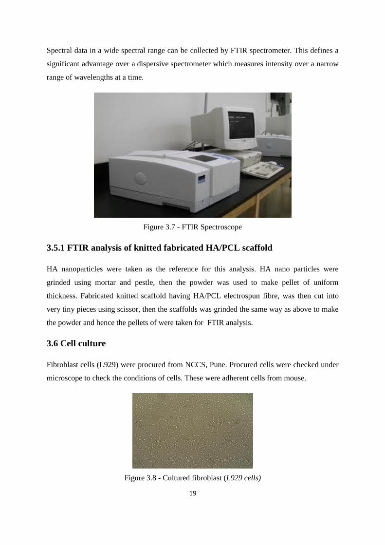
Spectral data in a wide spectral range can be collected by FTIR spectrometer. This defines a
significant advantage over a dispersive spectrometer which measures intensity over a narrow
range of wavelengths at a time.
Figure 3.7 - FTIR Spectroscope
3.5.1 FTIR analysis of knitted fabricated HA/PCL scaffold
HA nanoparticles were taken as the reference for this analysis. HA nano particles were
grinded using mortar and pestle, then the powder was used to make pellet of uniform
thickness. Fabricated knitted scaffold having HA/PCL electrospun fibre, was then cut into
very tiny pieces using scissor, then the scaffolds was grinded the same way as above to make
the powder and hence the pellets of were taken for FTIR analysis.
3.6 Cell culture
Fibroblast cells (L929) were procured from NCCS, Pune. Procured cells were checked under
microscope to check the conditions of cells. These were adherent cells from mouse.
Figure 3.8 - Cultured fibroblast (L929 cells)

20
3.6.1 Preparation of DMEM
7.65gm of AT-139A-1L, 0.1825gm of L-glutamine, 0.6gm of NaHCO3 was added to 400ml
of autoclaved distilled water. PH
of the medium was adjusted to 7.4 (if needed by addition of
0.1N NaOH).Then the medium volume was adjusted to 500ml adding additional water
.Medium was then filtered for further use.10%FBS was added to the medium before adding
medium to the cells. The cells were then transferred to new flasks having 10ml of
DMEM+10%FBS.Cells were observed under microscope every day to check the condition of
cells. When cells were found confluent enough in the flask they were subcultured.
3.6.2 Sub-culturing of cells
The old media is first removed from the cells by pipette and discarded. The cells are then
washed twice with 5ml PBS, and the waste was discarded. The cells are then trypsinised to
loosen them from the culture-dish. About 1 ml of trypsin was added to all the flasks and were
incubated for 5 mins. Hence, flask was checked under microscope whether cells had been
detached or not. If not, flasks were again kept for more 5 mins allowing cells to detach
completely. Then 5 ml of DMEM was added to flasks and all cells were taken out in a 15ml
centrifuge tube after that again 5ml of DMEM was added to flasks and was pipetted to the
tube. Thus the tubes were centrifuged at 2000g for 10 mins. After completion of
centrifugation the pellets were pipetted using 5ml of DMEM having 10%FBS.Then extra 5ml
of DMEM+10%FBS was added before incubating cells in incubator.
3.7 Cell Seeding
Scaffolds were kept in 5ml of 70% ethanol for 24 hours inside bio-safety cabinet to sterilise
it. L929 Cells were seeded on sterilised scaffold and the scaffold was maintained in DMEM
medium having 10% FBS. Cell adhesion test was done to check the attachment efficiency of
cells on scaffold.
3.7.1 Mechanical testing of cell seeded scaffold
Tensile strength of cell seeded scaffold was tested using TA-HDPlus Texture Analyser.

21
3.7.2 Cell viability test
Propidium iodide (or PI) is an intercalating agent and a fluorescent molecule was used to
stain cells. Propidium iodide was used as a DNA stain to evaluate cell viability or DNA
content in cell cycle analysis and microscopy to visualise the nucleus and other DNA
containing organelles.
3.7.3 Cell proliferation test
MTT Assay: The cells were preincubated at a concentration of 1 × 10⁶ cells/ml in culture
medium for 3 hrs at 37°C and 4 % CO2. Then, the cells were seeded at a concentration of 5 ×
104 cells/ well in 100 µl culture medium and at various concentrations (0.005-100 µg/ml) of
standard Cells (dissolved in 2% DMSO (dimethylsulphoxide) solution) into microplate (96
wells having flat bottom) and was incubated for 24 hrs at 37°C and 5% CO2. The cell
proliferation is based on increasing in cell number by yellow-Orange colored propidium
iodide indicator. Then, 10 µl MTT labelling mixture was added and incubated for 4 hrs at
37°C and 5% CO2. Then 100 µl of solubilisation solution was added into each well and was
incubated for overnight. The absorbance of the samples by spectrometer was measured using
a microplate (ELISA-ELX-800) reader. The wavelength to measure absorbance of the dye in
between 550 and 600 nm according to the filters available for the ELISA reader was used.

22
CHAPTER - 4
RESULTS AND
DISCUSSIONS

23
4. Results and Discussions
4.1 SEM Image
Figure 4.1 - SEM image of Knitted Silk scaffold
Pore diameter and fibre diameter were found to be 0.822 mm and 0.064 mm respectively.
4.2 Mechanical testing results of knitted scaffold
Biodegradability test:
Table 4.1 Mechanical strength of scaffolds soaked in PBS
SL.
NO.
NUMBER OF
DAYS
TENSILE
STRENGTH
(MPa)
1. 0th
DAY 48.12±0.18
2. 3rd
DAY 46.2±0.64
3. 7th
DAY 34.4±0.24
4. 14th
DAY 14.1±0.21
5. 21st
DAY 6.75±0.37
24
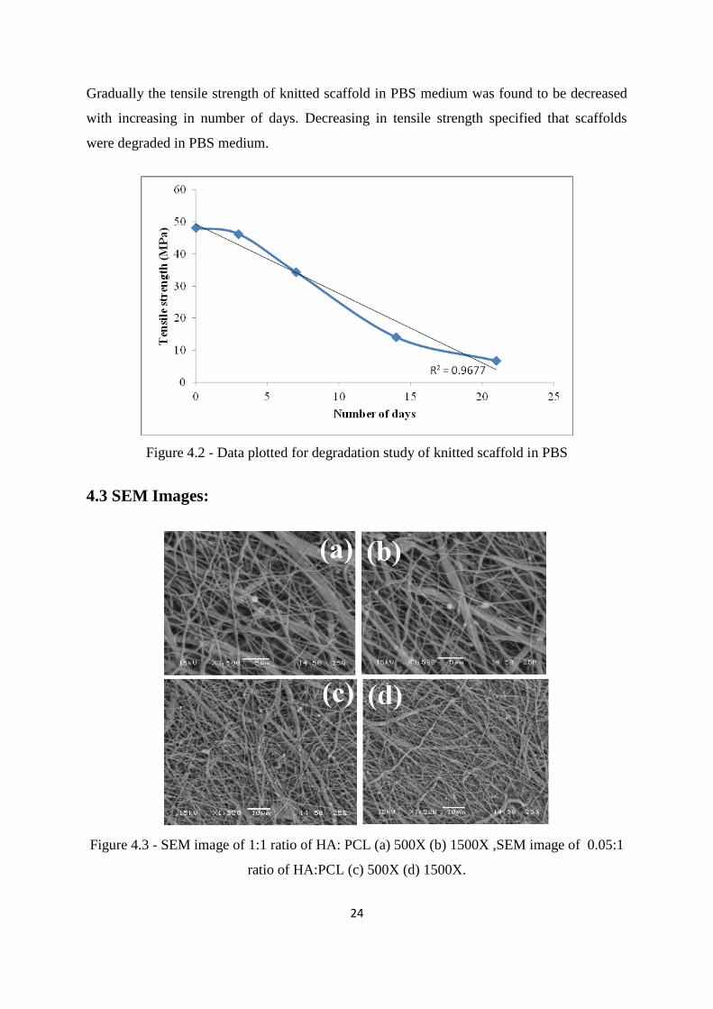
Gradually the tensile strength of knitted scaffold in PBS medium was found to be decreased
with increasing in number of days. Decreasing in tensile strength specified that scaffolds
were degraded in PBS medium.
Figure 4.2 - Data plotted for degradation study of knitted scaffold in PBS
4.3 SEM Images:
Figure 4.3 - SEM image of 1:1 ratio of HA: PCL (a) 500X (b) 1500X ,SEM image of 0.05:1
ratio of HA:PCL (c) 500X (d) 1500X.

25
Figure 4.4 - SEM image of electrospun HA: PCL fibre on knitted silk Scaffold
SEM analysis showed random alignment of electrospun HA/PCL fibres on knitted silk
scaffold. These nanofibres have diameter ranging from 335 nm to 686 nm. Surface area
increases with respect to decreasing in fibre diameter. Thus, increasing in surface area
provides enough potency for cell attachment and proliferation.
4.4 FTIR Results
Figure 4.5 – Plot between % of transmittance vs wavenumbers for 1:1 ratio of HA: PCL.

26
Figure 4.6 - Plot between % of transmittance vs wavenumbers for 0.05:1 ratio of HA: PCL.
The characteristic reflections of the vibrations PO43-
(950 cm-1
), were observed for both the
coatings. These reflections indicate the rearrangement of the polyhedrons of PO43-
in the
structure of the crystal. The band at (693, 679 cm-1
) and the sharp band at 3270 cm-1
are
characteristic for the apatite structure and are attributed to the vibration of OH- groups. The
broad band ranging from 3287 cm-1
can be explained owing to O-H group stretch vibration of
absorbed water.CO32-
incorporation was detected by the presence of the bands at 1422 and
1460 cm1 (CO3
2).
Figure 4.7 - Comparative FTIR study of HA-PCL in different concentration, (a) 1:1 ratio of
HA: PCL (b) 0.05:1 ratio of HA: PCL

27
The C-H peaks present at 1650cm-1
and 2356 cm-1
in Electrospun PCL remained unchanged
in the presence of HA. FTIR analysis has demonstrated that the electrospinning process has
no effect on the functional groups present in the resulting structure. When we compare
Electrospun HA & PCL Pellet the spectra reveal that there is no difference in the functional
groups present after electrospinning.
4.5 Fibroblast cell (L929) culture:
Figure 4.8 - Microscopic view of cultured adherent fibroblast (L929) cells.
4.6 Cell adhesion calculation:
Number of seeded cells = 0.6×10⁶
After incubation of 24 hours,
Number of cells in medium = 0.8×10⁵
Number of attached cells on scaffold = 52×104
% of cell adhesion =86.67%

28
4.7 Mechanical testing result of cell seeded scaffold:
Table 4.2 - Mechanical Strength for seeded scaffold
SL.
NO.
NUMBER
OF DAYS
TENSILE STRENGTH
(MPa)
1. 7th
DAY 41.875±0.22
2. 14th
DAY 46.875±0.38
4.8 MTT Assay results:
In addition, we found that the MTT assay is a more consistent model in predicting the
sensitivity and specificity of cells progression obtained from allograft models. The higher
sensitivity observed in assay may be in part due to extraordinary constant exposure to high
cell concentrations.
Figure 4.9 - The absorption rate result of MTT assay for fibroblast cells in 24 hrs.

29
CHAPTER -5
CONCLUSION AND
FUTURE WORK

30
5. Conclusion and Future work
Conclusion
Hence, a knitted silk scaffold was fabricated with electrospun HA/PCL nanoporous fibre.
Mechanical strength of cell seeded scaffold was found to be 46.875MPa, which is
comparable to that of bone (62MPa). The Scaffold was suitable for growth of adherent cells
like fibroblast as obtained from a higher percentage (86.67%) of cell adhesion. An increment
of 22% cell proliferation on 7th
day confirmed that the in-house fabricated scaffold is an
excellent platform for cell (fibroblast L929) attachment, growth and proliferation. Further, a
notable increase in mechanical property after cell seeding concludes a modification of
fibroblast that lead to abundant extracellular matrix deposition. This result needs further
confirmation by cell differentiation study.
Future work
In future, osteoblast would be used as the seeded cells in the bone compartment. Gene
expression study of the seeded cells on scaffold would be analysed through real time
polymerase chain reaction (RT-PCR). In addition, scaffolds would be cross linked with
suitable polymers before being fabricated with electrospun HA particles.

31

32
CHAPTER - 6
REFERENCES

33
6. References
1. Matyas, J.R..(1994): Analyzing nuclear shape as a function of relative spatial position
in the femoral insertion of the medial collateral ligament. Computer Methods
andPrograms in Biomedicine 44, 69- 77.
2. Huss, F.R(2005):In vitro and in vivo studies of tissue engineering in reconstructive
plastic surgery, Linköping.
3. Benjamin M, Kumai T, Milz S, Boszczyk AA and Ralphs JR.The skeletal attachments
of tendons-tendon ‘entheses’ comp biochem physiol A Mol Integr
Physio,.2002:133:931-945.
4. Woo,S.L.Y., Buckwalter and J.A.:Injury and Repair of the Musculoskeletal Soft
Tissues. American Academy of Orthopaedic Surgeons, Park Ridge, Illinois, 1988.
5. Amiel, D., Frank, C., Harwood, F., Fronek, J. and Akeson, W.,(1984): Tendons and,
ligaments: a morphological and biochemical comparison. Journal of Orthopaedic,
Research, 1, 257- 265.
6. Kastelic, J., Palley, I., and Baer, E.,(1978):The multicomposite ultrastructure of
tendon, Connective Tissue Research, 6, 11- 23.
7. Matyas, J.R., Anton, M.G., Shrive, N.G., and Frank, C.B.,(1995).:Stress governs
tissue,phenotype at the femoral insertion of the rabbit MCL. Journal of Biomechanics,
28, 147- 157.
8. Sadler TW, Langman's Medical Embryology. 6th ed, JN Gardner.(1990), Baltimore:
Williams & Wilkins. 411.
9. Reilly, G. C. and Currey, J. D.(1999).:The development of microcracking and failure
in bone depends on the loading mode to which it is adapted. J. Exp. Biol.202, 543–
552.
10. Stock UA, V.J.:Tissue engineering: current state and prospects.Annu Rev Med.,
(2001).52,443-51.

34
11. Athanasiou KA, N.G., and Agrawal CM.,:Sterilization, toxicity, biocompatibility and
clinical applications of polylactic acid/polyglycolic acid copolymers.Biomaterials.,
1996. 17(2), 93-103.
12. Sahoo S, O.H., Goh JC, Tay TE,and Toh SL.,:Characterization of a novel polymeric
scaffold for potential application in tendon/ligament tissue engineering. Tissue Eng.,
2006. 12(1), 91-9.
13. Wobus AM, B.K.,:Embryonic stem cells: prospects for developmental biology and
cell therapy.Physiol Rev, 2005. 85(2), 635-78.
14. Martin MJ, M.A., Gage F, and Varki A,:Human embryonic stem cells express an
immunogenic nonhuman sialic acid.Nat Med, 2005. 11(2), 228-32.
15. Tanaka H, M.P., Pruitt DL, and Larson BJ.,:Effect of cyclic tension on lacerated
flexor tendons in vitro.J Hand Surg [Am]. 1995. 20(3), 467-73.
16. R. Quarto, M. Mastrogiacomo, R. Cancedda, S. M.Kutepov, V. Mukhachev, A.
Lavroukov, and E. Kon, M.Marcacci, New Eng. J. Med. 2001, 344, 385.
17. C. S. Adams, K. Mansfield, R. L. Perlot, I. M. Shapiro, J. Biol. Chem. 2001, 276,
20316.
18. C. A. Heath, Trends Biotech. 2000, 18, 17
19. B. E. Reubinoff, M. F. Pera, C. Y. Fong, A. Trounson, A. Bongso, Nature Biotechnol.
2000, 18, 399.
20. A. J. Friedenstein, K. V. Petrakova, A. I. Kuroleso, G. P.Frolova, Transplantation
1968, 6, 230.
21. J. A. Jadlowiec, A. B. Celil, J. O. Hollinger, Expert. Opin.Biol. Ther. 2003, 3, 409
22. G. N. Bancroft, V. I. Sikavitsas, J. van den Dolder, T. L.Sheffield, C. G. Ambrose, J.
A. Jansen, A. G. Mikos, Proc.Natl. Acad. Sci. USA 2002, 99, 12600.