Embed Size (px)
Citation preview

Universidade do MinhoEscola de EngenhariaDepartamento de Informatica
Fabio Andre Araujo Gomes
Remote Management of Applications
Deployment of Applications and Configurationsusing a Rule system
October 2016

Universidade do MinhoEscola de EngenhariaDepartamento de Informatica
Fabio Andre Araujo Gomes
Remote Management of Applications
Deployment of Applications and Configurationsusing a Rule system
Master DissertationMaster Degree in Computer Science
Dissertation supervised byProfessor Victor Francisco Fonte, DI, UMMarco Cunha, Creativesystems
October 2016

i
When you see a good move, look for abetter one.
Emanuel Lasker

A C K N O W L E D G E M E N T S
I would first like to thank my thesis advisor Prof. Vıctor Fonte of the Informatics Depart-ment at University of Minho. He was always available whenever I ran into a problem orhad a question about my research or writing by steering me in the right direction wheneverhe thought I needed it.
I would also like to thank the experts at Creativesystems who were involved in the vali-dation and development for this research project: my co-advisor and Project Leader MarcoCunha who was the one in charge of evaluating its applicability to the company’s clients.Nuno Caleira, Project Manager, for the a constant support and for allowing me to join thecompany to create this dissertation. And to Jose Alvaro, my co-worker in the project andmentor. His expertise and advice during the planning and development phase were crucialfor this project success and without his enthusiastic assistance and input, this dissertationwould not end so well. Thank you all.
Finally, I must express my very profound gratitude to my parents and to my sister forproviding me with unfailing support and continuous encouragement throughout my longyears of study and through the process of researching and writing this thesis. This accom-plishment would not have been possible without them. Thank you.
ii

A B S T R A C T
Users expect access to programs and business information anywhere in the simplest waypossible using a device. With the diversification of devices, the standard is disappearingand we are going towards a more heterogeneous world of mobile devices. With this diver-gence increasing, it gets more difficult to update, support and control applications throughall these new platforms. Therefore it is important to facilitate these tasks.
The solution to these problems lies on the Mobile Device Management (MDM) programsthat can control what devices install and configure, providing remote tasks and access. Thisdissertation aims not to compete with the current products on the market, but to proposea different way to distribute content to the devices registered on the platform using a Rulesystem. This system will prioritize the newest rules by the device and its location charac-teristics. As so, providing a different way of grouping devices and distributing content tothem.
iii

R E S U M O
Os utilizadores esperam acesso aos programas e informacoes corporativas em qualquerlugar da forma mais simples possıvel, utilizando um dispositivo. Com a diversificacao dedispositivos, o standard esta a desaparecer e estamos a ir em direcao a um mundo maisheterogeneo de dispositivos moveis. Com esta crescente divergencia, torna-se mais difıcilde atualizar, dar suporte e controlar aplicacoes atraves de todas estas novas plataformas. Eentao importante que estas tarefas sejam facilitadas.
A solucao para estes problemas reside nos programas de MDM que podem controlaro que os dispositivos instalam e configuraram, proporcionando acesso e tarefas remotas.Esta dissertacao nao pretende competir com os produtos existentes no mercado, mas parapropor uma forma diferente de distribuir conteudo para os dispositivos registados naplataforma atraves de um sistema de Regras. Este sistema vai priorizar as regras maisrecentes por dispositivo e as caracterısticas da sua localizacao. Proporcionando uma formadiferente de agrupar dispositivos e distribuicao de conteudo para eles.
iv
C O N T E N T S
1 introduction 1
1.1 Main Challenges 2
1.2 Document Structure 3
2 mobile device management (mdm) 4
2.1 State of the Art 5
2.1.1 MDM Alternatives 6
2.1.1.1 Microsoft Intune 6
2.1.1.2 Amtel MDM 7
2.1.1.3 IBM MaaS360 7
2.1.1.4 AirWatch 8
2.1.1.5 MobileIron 9
2.1.1.6 Review 9
2.1.2 Dependencies 9
2.1.2.1 Dependency hell 10
2.1.2.2 Conflicting dependencies 10
2.1.2.3 Private per application versions 10
2.1.2.4 Package Manager 11
2.1.3 Cross-Platform Development 11
2.1.3.1 Xamarin 12
3 architecture 13
3.1 Agent 14
3.1.1 Logs 15
3.1.2 Registration and Device State 16
3.1.3 Installations 19
3.1.3.1 Installation and Restore 20
3.1.3.2 Updater 20
3.1.3.3 Batch Installations and Packages 21
3.1.4 Synchronization 22
3.2 Files 22
3.2.1 File Versions 22
3.2.2 Packages and Dependencies 23
3.3 Configurations 25
3.4 Groups 26
3.5 Sites 29
v

Contents vi
3.6 Rule System 29
3.6.1 Processing Rules 30
3.7 BackOffice 35
3.7.1 Users 35
3.7.2 Authentication and Communication 35
3.7.3 Roles and Permissions 35
3.8 Dashboard 36
4 implementation 38
4.1 Security 38
4.1.1 API-Keys 39
4.2 Database 39
4.2.1 PostgreSQL 40
4.2.2 SQLite 40
4.3 BackOffice 40
4.3.1 AngularJS 41
4.3.2 Dashboard Graphs - D3.js 42
4.3.3 Translations 42
4.4 Web Service 43
4.4.1 REST vs SOAP 43
4.4.1.1 REST 43
4.4.1.2 SOAP 44
4.4.1.3 Conclusion 45
4.4.2 ASP.NET Web API 46
4.4.3 Newtonsoft.Json 46
4.4.4 Npgsql 47
4.4.5 PetaPoco 47
4.4.6 AutoMapper 47
4.4.7 Apache log4net 48
4.4.8 Obfuscation 48
4.5 Agent and Updater 48
4.5.1 Preparing Cross-Platform 48
4.5.2 Android 50
4.6 System Review 51
4.6.1 Cloud Proposal 53
4.6.2 Security Analysis 53
5 conclusion 55
5.1 Ongoing Work 55
5.2 Future Work 56

Contents vii
a backoffice screenshots 61
a.1 Main Menu 61
a.2 Dashboard 62
a.3 Groups Graph Representation 63
a.4 Group Details 63
a.5 Issues Example 64
a.6 Role Details 65
a.7 User Role Details 66
a.8 Device Details 67
a.9 Device Status 68
b agent screenshots 69
b.1 Agent Main Menu 69
b.2 Device Information 70
b.3 Set WS URL 70
b.4 Not Approved Error Popup 71
b.5 Set Site 71
b.6 Checking for Updates 72
b.7 Downloading File Versions 72

L I S T O F F I G U R E S
Figure 1 Xamarin - Share code everywhere 12
Figure 2 Entities Diagram 14
Figure 3 Device States Diagram 16
Figure 4 Example of a Retail Customer’s Hierarchy 27
Figure 5 Representation of Figure 4’s dispersed Group Hierarchy 28
Figure 6 Representation of Figure 5’s Values 28
Figure 7 D3.js usage on Section 3.8’s Wrong Versions Dashboard 42
Figure 8 Cloud Architecture 53
Figure 9 Main Menu 61
Figure 10 Dashboard Tiles 62
Figure 11 Groups graph representation 63
Figure 12 Group Details of Brand 63
Figure 13 Issues example 64
Figure 14 Users only role example 65
Figure 15 User account displaying the available permissions 66
Figure 16 Device Details 67
Figure 17 Device Status showing what it has installed 68
Figure 18 Agent Main Menu 69
Figure 19 Device Information Menu 70
Figure 20 Set Web Service (WS) connection 70
Figure 21 Not Approved error popup message 71
Figure 22 Set Site 71
Figure 23 Requesting the WS for Updates 72
Figure 24 Downloading CS Mobile file version to be installed 72
viii

L I S T O F TA B L E S
Table 1 Example of Packages and Dependencies 24
Table 2 Example of a Configuration 26
Table 3 Example of 2 Configuration Values regarding the Configuration onTable 2 26
Table 4 Example of File Versions and Configurations 32
Table 5 Example of Groups and Group Values 32
Table 6 Example of Devices and Sites 32
Table 7 Example of Packages 33
Table 8 Example of Rules and File Versions for a Device 33
ix

L I S T O F L I S T I N G S
3.1 CS Agent.conf file . . . . . . . . . . . . . . . . . . . . . . . . . . . . . . . . . . 17
3.2 Installation Checks JSON response . . . . . . . . . . . . . . . . . . . . . . . . . 19
4.1 angular-gettext example in Angular.JS . . . . . . . . . . . . . . . . . . . . . . . . 42
4.2 Response as XML . . . . . . . . . . . . . . . . . . . . . . . . . . . . . . . . . . . 43
4.3 Response as JSON . . . . . . . . . . . . . . . . . . . . . . . . . . . . . . . . . . . 44
4.4 SOAP method signature . . . . . . . . . . . . . . . . . . . . . . . . . . . . . . . 44
4.5 SOAP request . . . . . . . . . . . . . . . . . . . . . . . . . . . . . . . . . . . . . 44
4.6 SOAP response . . . . . . . . . . . . . . . . . . . . . . . . . . . . . . . . . . . . 45
4.7 AutoMapper example . . . . . . . . . . . . . . . . . . . . . . . . . . . . . . . . 47
4.8 Container Registry example on Windows CE . . . . . . . . . . . . . . . . . . . 48
4.9 Container Registry example on Andoid . . . . . . . . . . . . . . . . . . . . . . . 48
4.10 IInstaller interface example . . . . . . . . . . . . . . . . . . . . . . . . . . . . . 49
4.11 Implementation of Install method on CabInstaller . . . . . . . . . . . . . . . . 49
4.12 Installation Logic example . . . . . . . . . . . . . . . . . . . . . . . . . . . . . . 50
4.13 Apk Install example . . . . . . . . . . . . . . . . . . . . . . . . . . . . . . . . . 51
x

List of Listings xi

1
I N T R O D U C T I O N
This thesis was proposed by Creativesystems (CS) to be part and incorporate the retail so-lutions on its clients. CS has in most of its customers hundreds of PDAs with versions ofapplications configured for a given feature such as to take care of store inventory or itemsreceiving. The maintenance of these devices is done manually when there is a need tochange any settings or carry out a software update. As there can be hundreds or thousandsof devices, the time needed to do a manual task in each device is very high. Whether forupdates or when providing support in case of failure, the normal procedure is to send someemployee to the site (e.g.: Warehouse, Store or Distribution Center) of the specific deviceand do the work manually. There is also the initial process of all this, the devices mustbe installed/configured at the time of its first installation with all the required software tooperate. In this case it is necessary that for each PDA someone is installing application byapplication individually resulting in a waste of precious time. So there are some drawbacksthat can be improved.
These problems are common for companies that have to control a huge number of de-vices, like CS where this dissertation takes place. The company doesn’t have a software ormechanism to remotely provide this kind of support to its clients. Software updates andconfigurations are common tasks and if there was a way to do them efficiently, it would beextremely helpful for both the client and CS.
This dissertation aims to research and develop a system capable of remotely manageapplications and settings for each device, along with an error analysis platform that can pro-actively give information to the user that a problem is or has happened. These problems canbe related to bad installations, configurations or hardware issues. The software must havea generic approach in order to be easily applied to all kinds of clients and its companiesstructures. This project will be applied to a client after its initial version is completed andused in future solutions of the company.
There are many software management platforms on the market and this dissertationwon’t try to compete with them, only suggest a new type of deployment mode, calledRule System, and devices’ organization. The developed solution will be called MDM, as itscharacteristics are similar to other products that share this device administration features.The first step is to gather information about the processes and methodologies in solutions
1

1.1. Main Challenges 2
that are currently on the clients. Understand its limitations and find the important featuresthat this project must have in order to be a valid approach. Then, a research on other MDMproducts has to be made and gather their important features and spot its flaws comparingwith the requirements. This project will be focused on the Retail business, due to the CSmarket place, but it should not be strictly designed for this area only and be generic enoughto be used on other environments.
1.1 main challenges
As there will certainly be more than hundreds of devices registered, the system will haveto handle that amount of traffic. This can be related to scalability. The diversification ofmobile devices will lead to different Operating Systems (OS’s) and architectures. The projectwill need to be agnostic to this kind of variations and proceed to the request handling asneutral as possible. As there will be applications for specific OS the devices can’t receiveupdates related to other OS.
The File Versions and Configurations that each device has to install will be calculatedbased on the Rule System. As these rules can be assigned to sites and group values, it isrequired to find the devices that are on the sites that match the selected values. Besides theversions that are grouped on packages and have to be expanded in order to retrieve the fulllist of file versions. This computing will be the most demanding operation on the system.These topics are explained thoroughly on the Chapter 3.
Being Windows CE the main mobile OS the CS customers use, this is clearly the focusof the first implementation. Released in 1996, Microsoft licenses Windows CE to OriginalEquipment Manufacturers (OEMs) so they can modify and create their own user interfacesand functionalities like RFID and barcode scanners. This OS usage is decreasing and moremodern systems are increasing like Android or iOS. But in order to do a complete shift, thecustomer have to remove all those old devices (usually RFID readers) to embrace the newerplatforms and that costs a lot of money. So the support for this OS is important, becauseMDM will be used on the devices the customer already have and don’t make them buy newones. The main target platform on Windows CE is the .NET Compact Framework which is acropped version of the .NET Framework which libraries are scaled down to use less space.Most methods were removed and the hardware limitations are challenging making thedevelopment for this devices a hard task. Because this has to be a future-aimed solution,the Windows CE can’t be the only supported mobile OS and for that matter it has to beimplemented with that focus and make the later development faster for those os, as thelogic base will already be defined.

1.2. Document Structure 3
1.2 document structure
The chapter where this section is included introduced the reader to the problem but thereare more chapters on this thesis, such as:
Chapter 2 Explains the concepts behind the MDM and in Section 2.1 some applicationsthat are already available on the market will be analysed.
Chapter 3 On the research I’ve done on the retail business, the company’s customersand the MDM solutions, this chapter has the general explanation of all theproject’s components and structure. With the definitions defined here, thedevelopment phase will take them in consideration.
Chapter 4 The implementation and some libraries used to help with the developmentare defined in this chapter, as well as a security analysis.
Chapter 5 I make the project’s evaluation and propose some future work that can bedone.
Appendix A Has screenshots to complement the thesis related to the BackOffice (BO).
Appendix B Agent Screenshots are shown here.

2
M O B I L E D E V I C E M A N A G E M E N T ( M D M )
MDM is a type of security software used by a company’s IT department to ensure security,access control, install software remotely, monitor, manage and secure employees’ mobiledevices that are deployed across multiple mobile service providers and OS’s. Optimizingfunctionalities and security of mobile devices within enterprise, while simultaneously pro-tecting the corporate network. In order to facilitate this control, a program is required tomake the connection between the device and the remote service that wants to control it,typically named Agent.
Bring Your Own Device (BYOD) is a theme that is growing recently due to the popular-ity of mobile devices and consequently leads to employees to use their devices on the jobrather than the company’s. It is already common in many businesses and in a 2012 Ciscosurvey that took place in the United States, 95 percent of the respondents said that ”theirorganizations permit employee-owned devices in the workplace.” (Cisco, 2012) This surveyalso estimated that the average ”knowledge worker” uses 2.8 connected devices at work.Usually this is an issue for the IT department in organizations as they have to manage theiremployees devices, to ensure information security and access control. The greater the vari-ety of devices and its quantity, the arduous it is to manage them. So the MDM is a servicethat is gaining impact and market presence as it appears to help these situations (Finneran,2011). According to Hayes and Kotwica (2013) four in ten enterprise level organizationshad a security breach related to BYOD.
The use of a management system as the MDM leads to a reduce of support costs andallows reports on the state of the device to be obtained, thus preventing problems by re-ducing the time in which the devices are unusable. During these situations of error, it isrequired that someone has to go to the device’s location and proceed with re-installationsor updates. If a program can do these requested operations remotely, the time to fix theproblems would be greatly reduced and cheaper.
The focus of this dissertation project is not to secure company information as it is one ofthe topics of the MDM’s implementations but it is focused on the applications installationand configuration and its deployment to the devices.
As Rhee et al. (2012) explains, there are five steps (which Step 4 and Step 5 are repeatedregularly and as needed) in a device life cycle on a MDM system:
4

2.1. State of the Art 5
Step 1 - Enrollment The mobile device data and user data of the organization are reg-istered in the MDM system and the policy to be applied to eachmobile device is configured.
Step 2 - Distribution The agent is distributed and installed in the users’ mobile devices.The agent can be distributed through the application store/marketor in-house.
Step 3 - Authentication When an agent runs after the installation, the mobile device data(IMEI, IP/MAC address, phone number, etc.) are sent to the MDMserver to verify if they match the data registered in the system.
Step 4 - Instruction The MDM server sends to an agent the mobile device control pol-icy and commands like ”remote wipe” according to the mobiledevice status data and user.
Step 5 - Control/Report The agent controls the functions of the mobile device according tothe mobile device control policy/command and reports the resultsto the MDM server.
These steps were taken in consideration during the project development. As this is agrowing theme, there are many MDM solutions available and the next section will analysesome of them to obtain information and collect procedures and the best methodologies thatthey have to include in this project.
2.1 state of the art
The first thing to do before starting to think in a project’s implementation or structureis to do a research on the subject. It will teach a lot about the research problem and byreading literature related to it I will learn from other researchers, becoming easier for meto understand and analyse the problem. It proves that this thesis problem has relevanceand if many people are trying to solve the same problem as me, I hope to prove that thisproblem I am trying to solve is important. In this section I will present some of the mostpopular MDM solutions with their advantages and drawbacks by relating them to the thesisrequirements to the software I am planning to make.
During the development, some difficulties will arise and before stepping into them in thelater phase, some can be prepared and studied in the research stage. These are the cases ofdependency resolution, distribution and cross-platform support.

2.1. State of the Art 6
2.1.1 MDM Alternatives
There are on the market several MDM solutions, on this section I present the ones that Iconsider the most important and popular in the enterprise world. Some requirements areset as essential so that a solution can be defined as potentially able to be used:
Windows CE support This OS is critical due to the handheld devices on the clients, e.g.Motorola MC55A or Denso BHT-1281 running on WinCE.
Android or iOS support Have at least one mobile OS supported besides the WinCE.
Easy setup Quick/simple installation of the MDM system configurations. Thesteps needed to install the MDM on a clean device have to be easierand shorter as possible to facilitate a new device registration onthe system.
Device Grouping A method to group devices.
Devices and Locations Link devices to sites/stores so that a device becomes related tothe location that it physically belongs.
App Versions Have multiple release versions per application and don’t over-write the old ones.
Deploy Apps to groups Distinct devices can receive different applications. Don’t alwaysdeploy a new version to all the devices but have the possibility todeploy it to a limited list of them.
Organize Locations Define the company’s internal sites/stores organization and relatedevices and its locations to it.
Install and Configure Install apps and apply configurations on the device.
Log the actions Perform logging and report device’s execution steps and status toa server.
2.1.1.1 Microsoft Intune
Microsoft has a paid management system, data, mobile devices and computers protectionapplication called Microsoft Intune 1 included in the Enterprise Mobility Suite. It is managedthrough a web interface and allows you to control what devices can install and run anddefine some system settings through policies. It is focused on companies with multipledevices for their employees and the notion of BYOD.
1 Web Page: www.microsoft.com/pt-pt/server-cloud/products/microsoft-intune/

2.1. State of the Art 7
It doesn’t need an infrastructure to do the management because it is in the cloud andcan also integrate with System Center Configuration Manager in this respect thus extendingthe existing policies. Without the need to buy some servers and bandwidth contracts, thiscloud environment is getting popular as it is cheaper to extend the capacity or power thanit is by doing it internally.
Intune resembles with what the company intends as it includes devices registration,application control, it groups devices, reporting, configures Wi-Fi/VPN, it supports Win-dows/iOS/OSX/Android and remote application delivery. It also contains the Mobile Ap-plication Management (MAM) with Office and multi-identity, allowing for example to blocksome user to copy enterprise information documents.
The control that you want to have with the devices must be passed to the customer andthe company will have access only to support scenarios. Plus it has a limit of 7,000 usersand 4,000 devices or 25,000 users and 50,000 devices only contemplating the Intune’s MDMsolution. These values seem satisfactory at first glance, but several CS customers have ahigher number of devices and can be a problem in the future as the solution grows. Thepartial support for Windows CE makes this a possible option but these usage limits are notenough in most existing customers.
2.1.1.2 Amtel MDM
Amtel is the only vendor that provides Software as a Service (SaaS) solutions for 3 mobiledevices business management aspects - Security, MAM and Cost Control. A web pagecontrols all the solution with the same system of rules, settings, dashboards and reportingsimplifying mobile collaboration in companies, leading to better productivity.
The MAM2 product restricts access and actions to mobile devices by keeping a barrierbetween the device’s public/personal use and private enterprise applications. It also dis-tributes applications with access to a private store where users can do installations. Youcan send application updates, order to remove applications, block applications access andusage, distribute recommended applications, configure the device and it is compatible withApp Store for iOS and Play Store for Android.
This solution is only present in iOS and Android, so it is not a valid option to use in thecompany’s projects that require Windows CE.
2.1.1.3 IBM MaaS360
Started by Fiberlink and now part of IBM, MaaS360 3 has great tools for MDM by supportinga great variety of mobile OS’s like Symbian and Blackberry besides Windows and OSX. This
2 Web Page: https://www.amtelnet.com/solutions/mobile-security/mobile-apps-management/3 Web Page: http://www.maas360.com/products/mobile-device-management/

2.1. State of the Art 8
solution includes a document with the BYOD’s ten commandments (Tsang, 2016) wherethey explain its focus on MDM.
As expected, it allows the devices registration through their application, contains controland settings policies, has its infrastructure in the cloud, it allows remote actions on the de-vice such as deleting data, lock the phone, get its location, hardware and status information,a catalog of applications and document sharing.
The distribution of single or packed applications for groups of users or devices is onerequired feature so that the MDM which the CS will use must contain. MaaS360 has thisimportant feature, which is lacking or not good enough on the previous solutions. It has agood list of features and it is very focused on solving the problems of BYOD which makesit a good choice for companies seeking this type of control. The lack of support for WindowsCE makes this not a viable option for the company’s requirements.
2.1.1.4 AirWatch
As an Enterprise Mobility Management (EMM) software, AirWatch4 is a software and stan-dalone management system for content, applications and e-mail. The goal of EMM is todetermine if and how available mobile IT should be integrated with work processes andobjectives, and how to support workers when they are using these devices in the workplace(Kietzmann et al., 2013). This software allows the access to work apps and information di-rectly from a mobile device in a simple way. The access to those work apps is done withoutthe need to worry about joining a VPN, manually setting up existing apps, or entering cre-dentials for the AirWatch apps. The login is done using only the corporate e-mail. AirWatchhas serious concerns about privacy by ensuring each client’s personal information and dataare kept separate from the work apps. With AirWatch, the IT department can securely pro-vide business resources and apps to their devices while keeping their personal informationprivate.
Regarding the Agent, it can be used to view the Device details, access up-to-date informa-tion and make sure you’re following the rules set by the IT, access important messages sentby the IT department or contact the IT admins via phone or e-mail for additional support,configure telecom management to ensure the data usage doesn’t exceed limits set by the ITdepartment and completely separate corporate data from the personal stuff by keeping thework apps and data in separate containers.
The Catalog has the purpose to browse and install work applications from the company’sown app store so that the users can access the applications recommended by the IT depart-ment across all of the enrolled devices. Contains the ability to browse the apps by categoryfor quick and easy access and rate and review both public and internal apps by makingcomments visible to other users.
4 Web Page: http://www.vmware.com/products/enterprise-mobility-management.html

2.1. State of the Art 9
The enrollment process in AirWatch uses profiles that have been pre-set by the adminis-trator based on device type, ownership model or organization group and when a deviceis registered, the Agent automatically begins downloading the matching profile. Adminis-trators create profiles from the AirWatch console that push enterprise applications, enablemonitoring and enforce automated compliance through the AirWatch compliance engine.AirWatch (2016) discusses common enterprise use cases and define the advantages of MDM,containerization and the security benefits that may be realized when both are deployed to-gether.
2.1.1.5 MobileIron
Just like the previous products, MobileIron 5 ensures data protection and applications controlon the devices. Started in 2009, they proclaim themselves as the the EMM leaders. TheMDM functionalities are focused on information security and mobile device configurationof different OS’s supporting safe e-mail, automatic configurations, security via certificatesand corporate data wipe. This is the purpose of their MDM, provide the companies secureand control insurances over mobile devices, applications and provided content, protectingthe employee’s privacy.
MAM is another set of functionalities which purpose is the deployment of applications tothe employees devices. It includes an application catalogue, authentication access controland separation of personal and corporate applications.
The glsmdm and MAM solutions provide corporate data protection and applicationsavailability but there is no support for Windows CE, the most important requirement.
2.1.1.6 Review
Any of the solutions presented in the previous section could not fully meet the essentialrequirements, but Microsoft Intune is the one that is closest to the desired features failingon the usage limits and the AirWatch is the market leader and has the customer successstories to prove it. Therefore, it will be developed a new MDM. The company is known forsolutions tailored for the customers and it is intended that this solution is generic enoughso that some changes required by the customers become minimal.
2.1.2 Dependencies
In software engineering, dependency is the degree to which each program module relieson each one of the other modules so when a class A uses another class or interface B, then A
depends on B. A cannot complete it’s work without B. For this reason the class A is called the
5 Web Page: http://www.mobileiron.com/

2.1. State of the Art 10
dependant and the class or interface B is called the dependency. A dependant depends on itsdependencies and this dependency is directional. Meaning that if A depends on B, it doesn’tmean that B also depends on A. In the cases that there is a relation between two or moremodules which either directly or indirectly depend on each other to function properly, it iscalled Circular Dependency.
Some challenges with shared libraries can happen as it is common for applications to useexternal dependencies relying on dynamic library linking, instead of static linking. Thisdynamic linking allows the sharing of executable libraries of machine instructions acrossapplications. In these scenarios, complex links between different applications that requiredistinct versions of libraries can result in a situation frequently known as Dependency Hell.
2.1.2.1 Dependency hell
Dependency Hell is a common term for the frustration of some software users who haveinstalled software packages which have dependencies on specific versions of other softwarepackages (Jang, 2006). A software usually uses libraries that are already available so that theprogrammer doesn’t have to code something that is already made, promoting reusability.However, in the software world, where components evolve rapidly and depend significantlyon one another, this problem becomes more pronounced (Donald, 2003).
This dependency issue appears around shared libraries on which other applications havedependencies but they depend on different (and sometimes incompatible) versions of theshared library. If the shared library can only be installed in a single version (only oneinstallation in the system), the user may have to address the problem by obtaining neweror older version of the dependent application. Which may lead to other dependenciesincorrect behaviour and push the problem to another set of applications.
2.1.2.2 Conflicting dependencies
Take the following example, App A depends on libExt 2.5, App B depends on libExt 3.0
and different versions of libExt cannot be simultaneously installed on the system, thereforeApp A and App B cannot simultaneously be used because libExt can only have one versioninstalled. A solution is the libExt to allow simultaneous installations, unlocking the usageof different versions.
2.1.2.3 Private per application versions
Private DLLs are a solution used on Windows OS to prevent dependency hell. There arecopies of libraries per application in its directory (where it is installed). When the applica-tion requests the libraries, first it searches on the local installation path so that it is alwaysprioritized and then it searches on the system directory with the system wide libraries.

2.1. State of the Art 11
Dealing with dependencies is not easy and can lead to problems like malfunctional pro-grams. To address these problems, the Package Managers appeared.
2.1.2.4 Package Manager
A Package Manager is a collection of software tools that automates the process of installing,upgrading, configuring, and removing programs. A package manager deals with packages,distributions of software and data in archive files. Packages contain metadata with informa-tion about it and the most important is the list of its required dependencies so that it canrun properly. Package Managers maintain a database of software dependencies and versioninformation to prevent software version disparity and missing prerequisites.
The RPM Package Manager is one of the most popular package managers used in manyLinux distributions.
2.1.3 Cross-Platform Development
A cross-platform software is a computer software that is implemented to execute on multi-ple computing platforms, typically OS’s. Cross-platform software may be divided into twotypes: it requires individual compilation for each platform that it supports or it can be di-rectly run on any supported platform without special preparation. For instance, a compiledJava code can run on all platforms that support Java without the need for recompilation.
As this MDM project first OS implementation is targeted to be Windows CE, Java can’tbe considered as it is not supported. Windows CE has .NET Compact Framework as the mainframework for development, suggesting the usage of C# as the desired programming lan-guage. With the Mono Project software platform6, it is possible to create a cross-platformC# application. Started in 2002 and currently maintained by Xamarin, It is an open sourceimplementation of Microsoft’s .NET Framework based on the ECMA standards for C# andthe Common Language Runtime. It brings the .NET capability to other OS’s like Linuxand macOS providing a runtime environment to execute .NET programs, compilers for var-ious source languages and implementations of the core class libraries specified in ISO/IEC23271 (ISO, 2012). Several books discuss development with Mono, such as Schonig andGeschwinde (2004); Kaan (2007); Dumbill and Bornstein (2004); Mamone (2006). Other im-plementations can be found in King and Easton (2004). But Mono doesn’t directly supportAndroid and for that scenario Xamarin appeared.
6 Web Page: http://www.mono-project.com/

2.1. State of the Art 12
2.1.3.1 Xamarin
With a C#-shared codebase, developers can use Xamarin7 tools to write native Android, iOS,and Windows apps with native user interfaces and share code across multiple platforms.With the Windows CE’s C# requirement and the Xamarin mobile OS support, this platformis ideal.
The MDM logic will be the same independently of the OS and if it is written only onetime, then the major concern when supporting a new OS will be the Graphical User Interface(GUI) that will be specific for each one.
Figure 1.: Xamarin - Share code everywhere
7 Web Page: https://www.xamarin.com/platform

3
A R C H I T E C T U R E
As this proposal is to be used in the future CS’s client releases, it is obvious that a workingsolution has to be implemented. This development will test the Rule System and GroupHierarchies concepts on real-life scenarios. The majority of devices used by the clients haveWindows CE as their OS, making it the logical choice for the target of the first implementa-tion. The following decisions will take this decision in consideration.
The installation, configuration and updating of applications on the device should behandled by an Agent (3.1) that is necessarily installed on each device. Its single point ofcommunication with the server is done through a Application Programming Interface (API).This remote service is responsible for informing the Agent which versions of applicationsand configurations it must install and provide all the necessary information about them,like name, version, size and file transferring details. The WS will have to calculate, by therules created by the customer, what File Versions and Configurations have to be installedon each device. These Rules are assigned to a set of Groups Values, values which whencombined create a Site filtering. These Rules may even be as specific as indicating what aparticular device must install or configure. Groups and their Values will be organized bythe client in a generic way thus giving freedom to shape its company’s scheme as it sees fit,which is an important point as it allows a wider range of customers by reducing the needto create a solution of MDM specific to each new customer. This management should bedone on a BO, a web application that will connect the user to the system.
Additionally, this solution should also be used to monitor the devices state, comparingwhat they have installed with what they should have installed or what errors occurredduring installations. This information will be available in a special part of the BO calledDashboard. Its purpose is to display the status of the entire system to the user, allowingthe customer to have a vision of what is working and what is failing.
13

3.1. Agent 14
Figure 2.: Entities Diagram
Figure 2 is an UML Entity–Relationship model that links all the entities represented thesystem. Each entity has a section in this chapter that explains its function and importance.
A Device can have installed many File Versions, each File Version is related to one Fileand can have one Configuration. A Device creates many logs and can have a Site set. Thisis an example of some knowledge that can be extracted from this model and it can be usedto implement the Database (DB). The Users are not linked in the diagram because it wouldgenerate arrows connecting all the entities, as the User exists in the BO’s context and it’sresponsible for handling the entities CRUD, I didn’t include it in the main diagram.
3.1 agent
Monitoring application updates imply that there is an entity controlling the search, notifica-tion and installation of them. It is intended that this entity is configurable and is installedon multiple devices with different OS’s to manage the versions of the applications and re-

3.1. Agent 15
port the system status. In case of any updates installation, it should be able to safely installthem so that if a problem happens, a roll-back is possible to the previous working state. Inaddition to applications, it is also necessary to be able to configure settings, such as chang-ing system variables/registry and transfer files by placing them in specific folders. This isthe Agent, the entity that will coordinate the updates on the devices.
The Agent is the application that the user will use to manage the device, it will connectwith the WS through an API to synchronize and fetch the necessary data. It has variousmenus (Figure 18 on Section B.1) for the user to navigate and view the device information,check for updates, change the Agent settings, restore installations, change the site and forcethe synchronization.
There are some important procedures like Logs (Section 3.1.1), Registration (Section 3.1.2),Installation (Section 3.1.3), Updater (Section 3.1.3.2) and Synchronization (Section 3.1.4) thatare explained on the respective sections.
3.1.1 Logs
Logging is the act of keeping a log that records events and information about a program’sexecution. A data collection method that automatically captures the type, content, or time oftransactions made by a person from a terminal with that system, as Rice (1983) defined. Thisinformation is generally used by programmers for debugging purposes and by softwaremonitoring tools to diagnose problems with software.
During any action, the Agent will produce logs reporting the progress and outcome ofthose operations. For instance, an installation log has the corresponding File Version orConfiguration identifier for future easier reference and linking. I characterized 2 types oflog storage:
Database The logs stored in the DB will use the identifiers (id’s) that came from the WS tolink all the actions. With this direct information, the Dashboard (Section 3.8) canuse it to perform better data analysis and the server to know for sure what FileVersion or Package it is related.
Files File-based logs contain some outputs and errors that the Agent produces duringits execution and will be used for later support to find errors, dumps and stack-traces. This type of logs will be helpful for the developers to use informationfrom the devices that are on the client. As there are log levels, the trace log canhave more or less output information. This log level can be changed remotely torequest more detailed logs from a device when necessary.
These logs are sent during synchronizations and erased from the device as soon as theyare uploaded. Therefore, inform the WS what a device has installed and configured and

3.1. Agent 16
what it has been doing as it is important for later support, to know what the Agent wasperforming and what was its state. The Database Logs are important for the server statis-tics and workflow, being the File Logs used only for later support reasons when necessarybecause the information on the Database Logs may not be enough to understand the situa-tion.
Database Logs can be linked to form a tree structure in order to relate a log to a parent log.This connections are important to understand what originated that action, for instance, toknow if a certain application was installed from a package. This linkage is more importanton Packages (Section 3.2.2) because a package can be marked as not installed if one of itsfile versions failed during its installation and with this linking it is possible to understandthe operations that the Agent made. Every File Log is associated with a Database Log anda File, with it the user can access the corresponding log. Check Section A.5 for an exampleof a log with a tree representation.
3.1.2 Registration and Device State
For a device to enroll in the system, it has to go through a registration process. During thisregistration, the device will inform the WS about its characteristics such as Serial Number,OS Version, Manufacturer and Brand. After this request, the agent will have to wait for itto be approved.
There are 2 boolean states that a device has, Approval and Enable. The Approval statewill focus on the device’s initial phase that will manage the Registration and when it re-quests a Site change, after it is approved the Enabled state manages the rest of its life untilit is deleted. Figure 3 illustrates the 4 Device States Phases.
Figure 3.: Device States Diagram

3.1. Agent 17
Phase 1
The registration request is the first action the Agent will do to enrol itself. After this request,it will be marked as Disapproved and Disabled. In this state, a User on the BO will have toapprove the device in order to proceed to the next phase, or reject it and the device will bedeleted.
Phase 2
When the Device is approved the Agent will receive the WS endpoints, the Agent andUpdater id file’s, its API-KEY and the Site that it is in. Because the endpoints are sent fromthe WS when the device requests its profile data, the server can change them without theneed of an Agent update as the result of an Uniform Resource Identifier (URI) modification.
In order to facilitate the registration of a Device and taking into consideration that onlyapproved devices can use the MDM, it is required a quick start mode. A config file can beset in the MDM’s installation folder that will contain the WS endpoint and some defaultconfigurations:
URL_DefaultHost=www.mdm.uminho.com
URL_DefaultPath=api/v1/mdm/
URL_DefaultProtocol=HTTPS
PORT =443
LANGUAGE=EN
Listing 3.1: CS Agent.conf file
If this file is not present, the Agent will launch with default settings and will promptthe user to type the WS endpoint as seen on Section B.3. This startup file skips the initialsystem configuration that consumes time and can lead to errors or bad configurations. Ifa device was previously registered on the system, the Agent will boot up directly to theMain Menu. When Denso devices battery is drained out, sometimes they lose all their databecause the devices do a hard reset and this file can be a way to ensure the Agent willinstall and start properly, recovering its state.
When using a new device, its addition to the system does not need to go through amanual registration in BO, so whenever a device tries to connect to the WS, the WS mustcheck whether it is already registered on the system via Device Number (hardware uniquecode). If it is not registered, the server makes an entry in the DB with its information. TheUser on the BO can complete its information or change it. With this method it is expectedthat the deployment on new Devices becomes quicker but the manual installation of theAgent is still required, which is the only operation required for the system to load properly.
Once a Device is approved and if a User haven’t assigned a Site to it, the Agent willrequest the person using the Device to select one from the available list. It is possible to

3.1. Agent 18
filter the list using Group Values (explained on Section 3.4 and represented on Section B.5).There is a particular situation in this case, once the Agent informs the WS the selected Siteit becomes assigned to it without the need of approval. But in the future, every time theAgent requests to change the site for its device, the device becomes disapproved until a BOUser approves the change by re-approving the device. In order to proceed to the next Phase,the Device must have a Site defined and be enabled and approved. This auto-approval caseis to ensure the quick-setup mode to skip a BO action.
So, 2 situations can occur in this phase when a user is going to approve a device registra-tion request:
User also sets a Site The user approves the device and sets a site to it, then the Agentdoesn’t have to request one and continues.
User doesn’t set a Site It is possible that the User is just accepting new registrations andnot assigning sites to them. In this case, the Agent will understandthat and request the User to choose one from the list.
Phase 3
This Phase contains all the operations a device does, like Synchronizations and Updates,until it is deleted and goes to Phase 4. In Phase 3 a Device can be disabled and enabled.A disabled device can’t operate until it is enabled. Once the Agent starts up or do anoperation, it will check the device state and inform the user about it if it is not allowed todo it. The device can be Disapproved if it requests a Site change, being in that mode untila User on the BO approves the change or sets a new Site.
Phase 4
A Device can be deleted from the system and won’t show up in the BO and it is the lastPhase a device will be. But it can come back and recover its definitions. If a device thatwas deleted registers itself again, it will go to the same process beginning on Phase 1 andthe WS will recover its data because its the same Serial Number and won’t make a newregistry.

3.1. Agent 19
3.1.3 Installations
In a device point of view, it needs to know what files it has to install and what configura-tions it needs to apply and in order to get that information, it has to request the WS aboutthat. The Agent just needs to get a list of file versions and configurations and proceed withits installation. The response looks like the content of Listing 3.2:
[
{
"id":103 ,
"id_InstallationPackage":null ,
"id_FileVersion":12 ,
"id_ConfigurationType":1 ,
"id_Configuration":10 ,
"InstallationOrder":null ,
"DestinationPath":null
},
{
"id":102 ,
"id_InstallationPackage":100 ,
"id_FileVersion":14 ,
"id_ConfigurationType":null ,
"id_Configuration":null ,
"InstallationOrder":1 ,
"DestinationPath":null
},
{
"id":102 ,
"id_InstallationPackage":100 ,
"id_FileVersion":112 ,
"id_ConfigurationType":null ,
"id_Configuration":null ,
"InstallationOrder":2 ,
"DestinationPath":"C:/path/to/copy/"
}
]
Listing 3.2: Installation Checks JSON response
The majority of this content are id’s because it is only required to get the full informationabout a File Version or a Configuration if the Agent has to install it or is not in its internalDB. This feature is intended to reduce traffic to the WS leading to less requests and informa-tion on payloads. The id’s will be used on Logs and on server requests. From this example,the Agent understands that it has to install File Version 12 with Configuration 10 and then

3.1. Agent 20
the Package 100 with two File Versions, first the 14th and then the 112 that will be copiedto a specific path.
3.1.3.1 Installation and Restore
Installing a File is quite simple and three installation methods were defined:
Copy Copy a file to a respective folder
Unzip Extract a compressed file to a respective folder (e.g.: .zip)
Install Install a file (e.g.: .cab)
The Agent before proceeding with an installation ensures that it has the installer fromthe currently installed version, if it does not then the Agent downloads it. This option isimportant if the new installation results in an error, the Agent can re-install the previouslyinstalled version. But if the installation is successful, then the Agent can delete the installerfrom the now previous version and retain only the current one. An installation can occurin an error by various reasons, like when extracting or copying a file to protected folders,the file is corrupted or by hardware reasons. So the Agent has to be prepared for thesesituations and whatever the outcome, a log file is uploaded that can be useful in errorsituations.
The Restore is an option that the User can use to re-install the current version of anapplication. If there is an online connection and there is an update to that application, theAgent only shows the update option forcing the application to be updated.
If a new application has been installed or a configuration applied, the Agent informs theWS about it during the synchronization. Like this, the WS has information regarding whateach Device has installed.
What if the application to install is an update for the Agent? The Agent would have toshut itself down and call the installing process. If any error occurred there would not beany logs. The solution is to create other entity, the Updater.
3.1.3.2 Updater
The Updater has only a single purpose, to update the Agent. This is an usual approachin software engineering, to create a separated program that will handle the update of themain application.
When the Agent detects the installation is an update for itself, by checking if the Fileid is equal to the Agent id that it gathered from the server, it calls the Updater informingwhere is the installer and it closes itself. This information is stored on the Registry and theUpdater will read from there. The Updater installs the Agent, logs the activity, marks the
3.1. Agent 21
installation as completed on the Registry and launches the Agent which will collect thoselogs and synchronize.
After its update, the Agent will continue with the rest of the installations if that is thecase. With this coordination, the User will update several applications, including the Agent,and just have to wait for all to finish because he won’t be prompted to any confirmation.This cycle is explained on the next section.
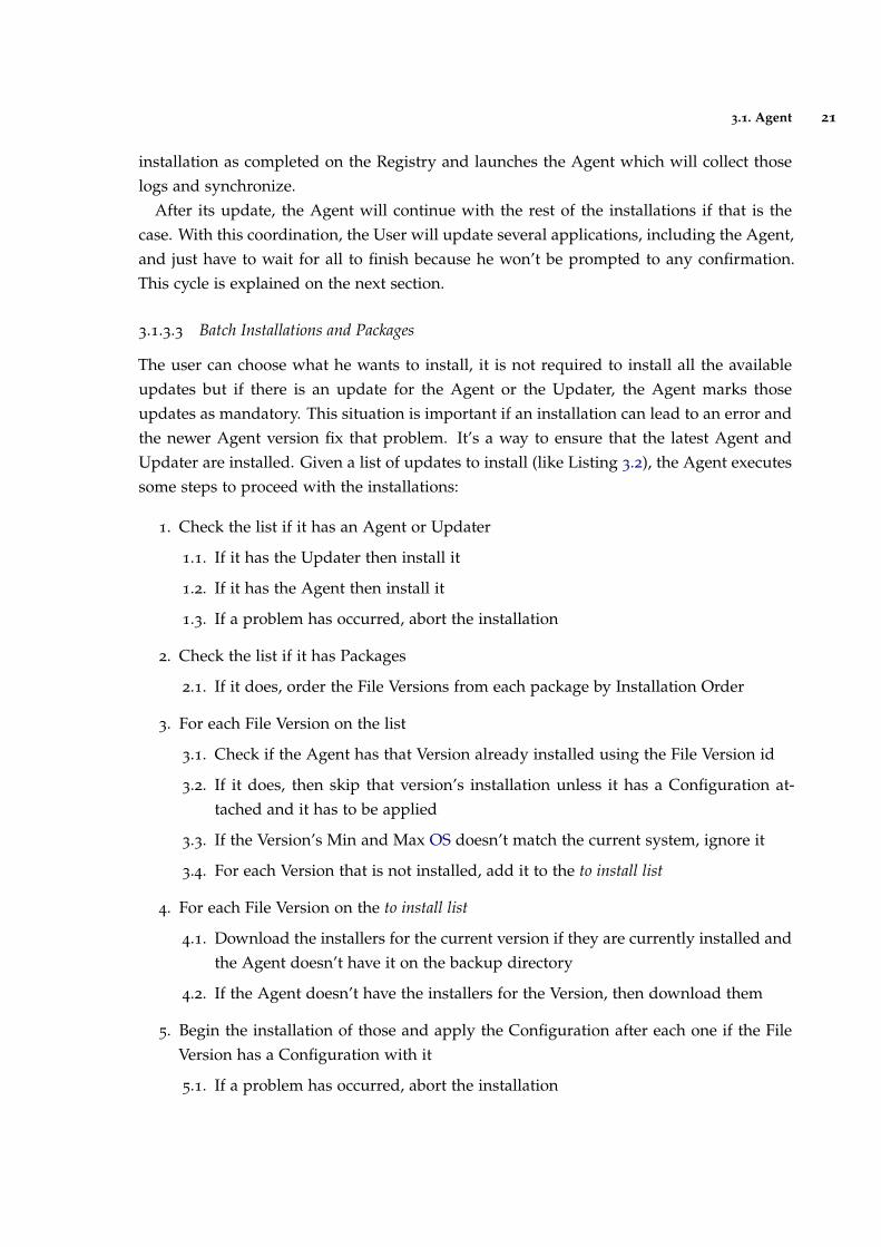
3.1.3.3 Batch Installations and Packages
The user can choose what he wants to install, it is not required to install all the availableupdates but if there is an update for the Agent or the Updater, the Agent marks thoseupdates as mandatory. This situation is important if an installation can lead to an error andthe newer Agent version fix that problem. It’s a way to ensure that the latest Agent andUpdater are installed. Given a list of updates to install (like Listing 3.2), the Agent executessome steps to proceed with the installations:
1. Check the list if it has an Agent or Updater
1.1. If it has the Updater then install it
1.2. If it has the Agent then install it
1.3. If a problem has occurred, abort the installation
2. Check the list if it has Packages
2.1. If it does, order the File Versions from each package by Installation Order
3. For each File Version on the list
3.1. Check if the Agent has that Version already installed using the File Version id
3.2. If it does, then skip that version’s installation unless it has a Configuration at-tached and it has to be applied
3.3. If the Version’s Min and Max OS doesn’t match the current system, ignore it
3.4. For each Version that is not installed, add it to the to install list
4. For each File Version on the to install list
4.1. Download the installers for the current version if they are currently installed andthe Agent doesn’t have it on the backup directory
4.2. If the Agent doesn’t have the installers for the Version, then download them
5. Begin the installation of those and apply the Configuration after each one if the FileVersion has a Configuration with it
5.1. If a problem has occurred, abort the installation

3.2. Files 22
Note that aborting the installation won’t revert to the old installation by default, it marksthat installation as failed. Example, if the package’s installation from Listing 3.2 installs FileVersion with id 14 and fails while installing File Version with id 112, the Package installationhas failed but the File Version id 14 has been installed successfully. To restore an applicationthe user has to access the specific menu to do that as it is not an automatic procedure.
3.1.4 Synchronization
Synchronization is the process of establishing consistency among the Agent’s DB and theserver’s data. It will keep the WS to be up-to-date with the state for each device. The syncis done whenever possible by the Agent and before important tasks that require the deviceto be synced, like the check for updates. The Agent sends the Database Logs and the FileLogs to the WS and when it receives a positive response, he deletes them from its DB andlog folder. The Database Logs contains 2 tables besides the logs themselves, the installedversions and the installed configurations.
3.2 files
A File is a representation of a computer file and has its basic characteristics, such as type(.cab or .apk to install, .zip to extract or a regular file to copy), OS, name, if it is Enabled ora Main Application. Multiple versions will be uploaded to the system regarding the sameFile as it is the way updates works, so it makes sense that only the changes are submittedas the information about the File remains the same. Dividing into File and File Version, itis possible to know that a Version X and Version Y belong to the File F. It will be usefulwhen launching Rules (Section 3.6).
A Main Application is taken into consideration as an important File and has a specialbehavior when creating Packages and treating dependencies. It is considered that a MainApplication may have dependencies on other no main files such as SQLite or .NET CF.
3.2.1 File Versions
When a File is created on the BO, the upload of its File Versions is unlocked and the Usercan upload its versions assigning them to that File. The User has to indicate its Versionthat has to be unique regarding all the versions for a file. This version identifier follows theMicrosoft’s Major, Minor, Build, and Revision scheme1. This scheme is also used to comparethe maximum/minimum versions of the OS’s that this version will run and should be seton the Version’s details if it is desired to use this filter. For instance, if a Version is not
1 https://msdn.microsoft.com/en-us/library/system.version.aspx

3.2. Files 23
intended to work on later versions of Windows CE 5.0, then it should not be released tothe Devices that doesn’t meet this criteria. Other attributes can be set, such as the sizerequired (useful for extraction or installations), the file path to copy if that is the case anda Configuration to be applied after its installation. The rest of the attributes are calculatedby the WS after the file upload, such as size, hash and file name.
There is no order or sequence on the File Versions upload, meaning that if a File hastwo versions uploaded, the third one resulting from the next upload don’t exactly meanthat it is the File’s most recent version just because it was the last one. So the order ofupload/creation is irrelevant.
It is possible to edit a File or a File Version’s details and even upload a replacing filefor that version, but the Agent won’t be notified of that change if it has already installedthat File Version. Meaning that the Agent won’t download that replaced file until the userrequests a restore because the Agent just only for more information (including its Hash)during the check for updates phase and only gets the full details when it doesn’t have thatversion installed (Section 3.1.3.3).
Because the File Versions are used on Rules and they are installed on Devices, it meansthat when the User wants to delete one from the system, a search for its usage has to bemade. So, it is only possible to delete a File Version if it is not used in any Rules andno Device has that version installed. Regarding the database, the entry can’t actually bedeleted because the File Version identifier is also used in Logs and obviously on the Historytables, so it is marked as deleted and won’t appear anywhere on the BO. The same strategyapplies to the File, it can only be deleted if all the File Versions related to it are removed.This is a usual behaviour when requesting a delete on any entity. There are history tablesto free the tables from the deleted entries, every update or delete on a monitored table willinsert the old row on the corresponding history table. This is done with triggers on themonitored tables.
The Agent has two methods to ask the WS about a File Version: get its meta info andrequest a download. The first one is used to get its information when the Agent gets itsid from an updates check. The second one is to download and internally store the file forits installation. This download request has an extra step that the Agent must perform afterits download, to check that the Hash from the downloaded file matches the meta info fromthe server in order to verify the integrity of the file. If the two hashes are the same, then theAgent can proceed with the installation.
3.2.2 Packages and Dependencies
Some applications may require other programs or libraries to work properly, called depen-dencies. These are some requisites that the Main Application must have to work properly

3.2. Files 24
and it may not work at all if any of those is missing. Meaning that when a BO user createsa rule demanding the installation of App X, he would have to create another one for eachof its dependencies. It would not be a helpful way of doing this because he may forget toadd one dependency and it won’t be reusable to future situations. Because of this need, thenotion of Package is introduced.
A Package is an ordered set of Files Versions which purpose is to indicate that a MainApplication needs other programs or configurations to work properly, called dependencies.The installation order indicates the Agent the course to take in the installation of all filesbecause the order may be important in resolving these dependencies. A Package can alsoinclude with each File Version a Configuration (Section 3.3) that will be applied at the endof the file installation in addition to the configuration that can be attached to the Versiongeneral definition.
There are some guidelines in the Package creation that must be met:
One Main Application There has to be exactly one Main Application in a Package
Ordered The File Versions are ordered
Same OS The Files on the Package must have the same OS as the Package’sMain Application or have an Undefined OS (e.g. text files)
The Agent will get a package and its content already ”expanded” and won’t have toquery the WS about it because when he requests it for what it has to install, the list willalready contain the files with the respective package and its order. The Agent will have todetect it and order those to proceed with the installations.
Take in consideration the following example:
Main Applications Regular FilesFA FBFE FC
FD
Package #1 #2 #3P1 FAV1 FBV1 FCV2
P2 FDV1 FEV1P3 FAV2 FCV2
P4 FAV2
Table 1.: Example of Packages and Dependencies
Following the example of Table 1, there are 2 underlined Files marked as Main Applica-tions: FA and FE and 3 Regular Files, FB, FC and FD. In Package P1, we have Version V1of the File FA, Version V1 of the File FB and Version 2 of the File FC. This means that FileFA needs those Versions of Files FB and FC. Later was released another Package for theFile FA, Package P3, which indicates that the new Version V2 of the File FA only needs FileFC’s Version V2. This loss of the need of File FB indicates that the FA no longer needs FB towork. By just creating a new package, it was possible to create new dependencies withoutmessing up with the older ones.

3.3. Configurations 25
Another situation has to be analysed, there is also the Package P4 that addresses the sameFAV2 as P3 also does. This could mean that some devices may already have FCV2 installedor it is not necessary for them, like drivers. So, there can be packages regarding the sameMain Application.
The creation of Packages don’t directly affect any device updates or installations unlessit is assigned to them by a Rule. This topic is addressed on Section 3.6 as the Packages haveinfluence in the Rules assignment and File Versions to install.
3.3 configurations
The main focus of any MAM is to be responsible for installing applications on devices,however some applications may require additional settings or even the devices themselves.A Configuration is linked to an OS and have a Configuration Values list. This link with theOS is important because some configurations may not be valid on other OS’s like WindowsRegistry values and Android Shared Preferences.
A Configuration Value contains a Type (string, number, boolean, ...) and a Key-Valuepair. The Value type is linked to a Configuration Type so that the Agent will know how toset that parameter. These Configuration Types can be Registry Values (Windows) or SharedPreferences (Android). Assuming Windows CE as the target environment, some Configura-tion Paths and Configuration Value Types are defined as:
Configuration Value Types for Windows CE:
• String
• Binary
• DWord
• . . .
Configuration Paths for Windows CE:
• Classes Root
• Current User
• Current Config
• Local Machine
• Users

3.4. Groups 26
With these definitions it is possible to simulate a Configuration:
Name App1 Config
Description Configure Language and Server Port for App1
Type Registry
OS Windows CE
Table 2.: Example of a Configuration
Configuration Value 1 Configuration Value 2Configuration App1 Config App1 Config
Description Language for the App Port for the server host
Key SOFTWARE/CS/APP1/Language SOFTWARE/CS/APP1/APIPort
Value PT 9876
Value Type String DWord
Path Local Machine Local Machine
Table 3.: Example of 2 Configuration Values regarding the Configuration on Table 2
The configuration called ”App1 Config” will create on the Registry two entries definingthe Language and Server Port for App1. Note that only Key, Value and Description arestored as values on the DB and Configuration, Value Type and Path are stored as foreignkey’s (id’s). The same occurs on Configuration’s Type and OS as these are only keys andName and Description as values. As a Configuration can have many values, this is a wayto save storage space and reuse data taking advantage of the DB.
3.4 groups
One of the objectives set to this dissertation was to propose a new approach respecting theorganization of devices. The research done on Section 2.1 was important to collect somedata on how other MDM solutions addressed this topic.
The general method that most of those MDM solutions used to tackle the organizationand grouping is to request the User to choose the devices that he wants to gather andcreate a new group. So, every new Device that would come to the system would have to beassigned to a group. This may work well for a relative small number of devices and offices,but this could lead to more problematic situations when the Updates become involved andthe number of devices increases. Because the project will be applied to retail customers,let’s take them as an example in the following generic scheme defining a sample hierarchyto illustrate how typically they are organized in Figure 4.

3.4. Groups 27
Figure 4.: Example of a Retail Customer’s Hierarchy
Company A has two Brands in their possession that are linked to Countries, the Brand A,which exists in Portugal and Spain and the Brand B that is located only in Portugal. Followingthe Brand A in Portugal the next segment is City and there are two of them, Braga and Faro.The City is the lowest segment because that is where you assign the Sites (Section 3.5) andplace the Devices. Sites Store B1 and Store B2 in Braga and Store P1 in Faro are highlightedin blue and have some Devices on them, highlighted in orange, ending the hierarchy.
Regarding this example, whenever you, as an administrator, add a new Brand you willhave to create a hierarchy similar to Brand A replicating that ”branch”. And as it can beseen, replication of data is one of many problems about this tree style approach. If we wantto describe the segments that the Store B1 belongs, we will have to start in Braga and pass byPortugal, Brand A and Company A. So, to define one Site it is required to set a value for eachsegment that structures the organization’s tree. Because different Brands are on differentsides of the tree, the same Country, Portugal, appears on both of them and can’t be assumedas to be the same. These are the main problems about this organization scheme. But thereis a simpler solution as an alternative, to break up the tree in order to make a more generichierarchy and re-use already created values like Portugal.
I propose that by splitting the tree from Figure 4, it will make the solution more genericand a more relaxed form of hierarchy. Allowing this implementation to be adaptable toother contexts beside retail. It is crucial that there is a dynamism in the creation of thehierarchy so that it is not necessary to create versions of MDM for each CS client becausethe structure of their organization is different, while also preventing the client to use astructure defined by the CS. It is up to each client to define the best hierarchy that reflectsthe organization of its company and so that this dissertation can be used outside of retailenvironments.

3.4. Groups 28
Using the example in Figure 4, it is simpler if the hierarchy is defined in a dispersedform:
Figure 5.: Representation of Figure 4’s dispersed Group Hierarchy
There are only two main ”trees” but more can be added without interfering with theones that already exist providing more detail on the definitions. In this Figure 5 an extrasegment named Mall can be added after the City to demonstrate the flexibility with thisscheme Country → City → Mall. These segments are called Groups and they will visuallyhelp to define the structure. The top-level groups are called Root Groups and each groupcan have one and only one link to another group. This link will make a subgroup have aparent group, e. g., Country is the parent of the City subgroup. The values like Portugal,Brand A or Faro presented on the example of Figure 4 are missing on this figure becausethey are defined inside each group:
Figure 6.: Representation of Figure 5’s Values
Figure 6 contains the Group Values definition of Figure 4 and just like the Groups, theseGroup Values also have a parent value to link them to an upper group value. Each Groupcan have multiple Group Values, as Country has Portugal and Spain and City has Bragaand Faro. Because there is a parent relative to each Group Value, the values from theRoot Groups have to be inserted first and as they are in the top, they don’t have a parentvalue. If the group called Mall was inserted after the City (being City the parent groupof Mall), the Group Values that already exists don’t have to be changed in any way. Toinsert a Mall value it would be Deluxe Shopping with Braga as its parent value, representingPortugal → Braga → Deluxe Shopping. Because Braga has Portugal as its parent, thisrepresentation is possible.

3.5. Sites 29
3.5 sites
A Site is the place where the Devices are located, such as a store, distribution center or awarehouse and has special features because it is the anchor between a Device and the MDMsystem. Each Site will have only one value per group branch, for instance, according to theexample in Figure 5 a Site will have a City and/or a Brand because you can only choosethe lowest Group Values of each branch. As stated before, each value has a reference to theGroup’s value above him and by pointing only to the lowest Group Value it is possible torecreate the values list to the root Group Value like Company or Country. It is not necessarilyrequired to have a value of each Group, only the ones necessary to characterize the Sitebecause the more Groups an organization has, the more detailed a Site can be.
Depending on the values assigned to it, the devices will receive updates based on thosevalues. Thus if a device changes its Site, the Versions that it has to install may change asthe new values on the new Site can be different causing different versions to install. Thissituation is explained in detail on Rules Section 3.6.
The dynamism created on the Groups will be reflected primarily in Sites because it issimple to define a Site, comparing to the previous example of Figure 4, it is only needed toassign a City and a Brand at most and values that can be changed later.
3.6 rule system
The purpose of the MDM is to assign applications to devices remotely and the Rule Systemwas conceived for that. A rule can be the release of a version of an application to the devicesin Braga’s sites or a language setting for all the devices that are in Portugal regardless of thebrand in question. It states what it is to install on which devices.
I defined a Rule as a pair of a Content and a Target. A Content is something to install,such as File Version, Package or a Configuration that a number of devices must have in-stalled. These devices are covered by the area of action from the Target definition such as aSite or Group Values. The previous definition of Group Values and its relation to Sites willmake the creation of rules an easy task.
The Content has three possible combinations:
• A File Version with or without an extra Configuration
• A Package with or without an extra Configuration
• Only a Configuration
Note that a File Version can have a Configuration and if it is associated to a Package, it canhave a second Configuration and if that package is on a rule with an optional configuration,

3.6. Rule System 30
there will be three levels of configurations. With these options, the client can use it to alterconfiguration values without the need to create newer configurations as the the order thatthe Agent will apply these configurations is from File Version, then the Package and thenfrom the Rule.
The Target also has 3 possible combinations:
• A Site with or without a Device
• Group Values with or without a Device
• Only a Device
If it is intended that the rule is to be applied to a specific device wherever it may beallocated, then the user selects it as the only target. To deploy a rule to more than onedevice there are three options as stated before: select a site and all the devices that are inthere will receive the update, select a set of Group Values to filter more than one site orcreate different rules with the same content targeting each device.
For the rules that target group values, the MDM system will have to find the sites thatmatch those values. This situation is explained on 3.6.1. Targeting a site or group values,both of these options can have a Device specified along with it and only when the device ison that site or on a site with those values, it will have that rule available. This is importantbecause a device can change its site and have different file versions when it is located on aspecific site.
The launch of a new Rule implies that other rules and respective versions of files maybe no longer considered if they are related to the same File. This is also the purpose ofthe Rules, to release newer versions and their dependencies to replace the older ones. Theconcept of dependencies on Packages is applied here again because version conflicts mustbe avoided. The calculation of versions and configurations to be installed by a device willbe the most computational demanding part, it will have to go through several tables if theDB is concerned. The latest rule by File will prevail, if it is associated with a package theAgent must also install its dependencies.
3.6.1 Processing Rules
As explained on the previous section, a rule can have three types of Content and Target,and depending on each, the effect of the rule is different. In order to calculate what a devicemust install, it is required to iterate the rules and process them, filtering out the ones thatdoesn’t matter for the specific device, like the ones to a Site that doesn’t belong to thatdevice or from a different OS.
The rules are prioritized by the creation date in a descending order, so the most recentrule is chosen over an older one regarding the same file. Because creating a rule for devices

3.6. Rule System 31
on sites in Braga can be a common creation, there should be a reuse in terms of the DBabout the group values when used in rules. If another rule for Braga is created, it can usethe same row id as the one created before without the need to create another DB entry. Thisdecision is useful to not replicate data and promote reusability.
The following procedure finds what a specific device must install:
1. If the device has a site, then go to 1.1.
1.1. Get the Site where the device is located
1.2. Get the list of rules that are assigned to that site
1.3. Get the list of group values from that site and then:
1.3.1. Get the group values assigned to the site and add it to the list
1.3.2. For each one of them, get its parent group value
1.3.3. If that group value also has a parent add it to the list and go to 1.3.2.
1.4. From the rules that target group values, get all those values
1.5. Intersect the values from 1.4. that match the values from the site list of 1.3.
1.6. Exclude the rules that have more values than the ones assigned to the Site
2. Get the rules assigned specifically to that device and add the ones from 1.6.
3. With the rules gathered so far (Target), proceed to find the file versions and configu-rations to install (Content):
3.1. Filter the rules related to the device’s OS or that have an undefined OS
3.2. Get the Main Application for the ones that have a package
3.3. Sort the rules in order to find the rule for the most recent file version by file,including the main applications from step 3.2.
3.4. If any file version from the previous filter is related to a package, then expandthe packages by listing all the file versions and linking them to the same rule
4. Get the configurations for the rules that only have it as content and add it to the list
5. Prepare the listing for the device
The step 1.6. will remove the rules that have more group values than the ones matchingthe site. For instance, if a Site A has only Brand A as its Group Value and a Rule is createdto Portugal and Brand A this Rule will be accepted on step 1.5. but it is not valid because itrequires the Brand Brand A and that site doesn’t have it, being rejected on step 1.6.

3.6. Rule System 32
Observe the following tables 4, 5, 6 and 7 that have the entities that will be used on theTable 8 to illustrate how the assigned rules dictate what a device has to install.
File File Version ConfigurationFA V1
FA V2 Conf1FA V3
FB V1
FB V2
FC V1
ConfigurationConf1Conf2Conf3
Table 4.: Example of File Versions and Configurations
There are three Files, FA, FB and FC with the respective Versions and three ConfigurationsConf1, Conf2 and Conf3. Note that FAV2 has Conf1 so when the Agent install this version itwill apply this configuration. The contents of the configurations are not important for thisexemplification and therefore they were not detailed.
Group Parent GroupCompany
Brand CompanyCountry
City Country
Group Value Group Parent Group ValueCompany Inc. Company
Brand A Brand Company Inc.Brand B Brand Company Inc.Portugal Country
Spain CountryBraga City Portugal
Madrid City Spain
Table 5.: Example of Groups and Group Values
The Groups and Group Values are reused from the previous sections.
Site Group ValuesSite1 Braga, Brand ASite2 Brand ASite3 Porto
Device SiteDeviceA Site1
DeviceB Site2
Table 6.: Example of Devices and Sites
Table 6 contains the Sites (with the Group Values for each one) and Devices (with theassigned site) that will be used on Table 8.

3.6. Rule System 33
Package #1 #2P1 FAV1 FBV2
P2 FAV2 + C2 FBV2
P3 FCV1 FBV1
Table 7.: Example of Packages
The Packages are listed on Table 7, indicating the File Versions and the respective instal-lation order, 1 and 2. Package P2 has an extra configuration, C2, that will be applied by theAgent after the installation of FAV2.
The following table includes rules with a time index, Content and Target. The greater thetime index the most recent the rule is, meaning that the rule 1 is older than 3.
Content Target
# File Version Configuration Package Site Device Group Values1 FAV1 Site2
2 FBV1 Spain3 FCV1 Site1 DeviceB
4 FCV1 Conf2 Site2 DeviceA
5 FAV1 Site1
6 P1 Portugal7 Conf3 P2 Site1
8 FAV2 DeviceA Braga9 FAV3 Site1
10 P3 Brand A, Portugal
Table 8.: Example of Rules and File Versions for a Device
DeviceA is the device used as the specimen in order to analyse the Table 8. This device asseen from Table 6 is located on Site1 which has Braga and Brand A as its Group Values (Table5). Let’s assume that the rules are launched one by one and we will evaluate each one andconsider the ones that came before. Consider also that the Files and Configurations fromTable 4 have the same OS as the device from this example.
Rule 1 is set for Site2 which is not where the device is located, so it is ignored.
Rule 2 is set for all the sites in Spain, as Site1 is in Portugal, this rule is also ignored.
Rule 3 is set for Site1 so it may be valid for our target device, but it is specific for DeviceB
and then it is ignored.
3.6. Rule System 34
Rule 4 besides being targeted for our DeviceA it is only when the device is on Site2. As itis on Site1 right now, it is discarded until it is moved to that location.
Rule 5 is aimed for Site1 only, meaning that this is a valid target. The content is the FAV1
and the only application the agent has to install.
Rule 6 was launched for sites in Portugal and as the site is in Braga, this is a valid rule aswe can see from the group values from Table 5. It requires to install the PackageP1 which contains FAV1 and FBV2. As it has FAV1, it will replace the last rule as ithas a version of FA with a new dependency FBV2. This rule can be interpreted asthe devices in Portugal, another version is required along with FAV1.
Rule 7 is like Rule 5, it is targeted for Site1 and therefore it is a valid rule for this device.It contains the Package P2 with an extra Configuration Conf3. This package has aspecial case because it contains the file FAV2 with an extra configuration, C2, andother file version, FBV2. The Table 4 shows that FAV2 has configuration C2 and asthe package also has an configuration, the Agent will apply C1 first an then the C2
from the package. But there is another configuration that was added on the ruledefinition, so the Agent will apply the C3 in the end completing the installation.With this rule, the agent will install this package because this version of FA prevailsover the previous rules because they only issued versions of FA.
Rule 8 is destined for DeviceA when it is in Braga and therefore it will be taken in con-sideration. This rule demands that this device installs FAV2 only, without extraconfigurations or dependencies as the previous rules demanded. Two situationscan occur, if the device is clean (or it was cleaned) of installations, the Agent will in-stall this version, being that the only version installed. But if the device applied allthe rules one after another, as those were timelined, the configurations C2 and C3
and the FBV2 may already be installed, and the FAV2 behavior may be influencedby that. This can occur because the Agent don’t uninstall applications.
Rule 9 is a valid rule for the device as it is targeted for Site1. It demands the installationof FAV3, replacing the previous rule.
Rule 10 is the last rule and it is intended for the sites in Portugal and that are a memberof Brand A. As the site belongs to both values, this rule is valid. The package thatthis rule issues has FCV1 and FBV1, as FC was never delivered before, it will beinstalled as well as the FAV3 from the previous rule.

3.7. BackOffice 35
3.7 backoffice
The client will have a Web portal called BO to perform all system management features.It’s purpose is to facilitate the administration routines and its interface is not seen by thestore costumers. It must be possible to perform all system administration tasks on the BO,such as approve and register Devices, create Rules, manage Groups and Values, create newVersions, etc. . . Like these actions, all the entities described on this chapter are managed inthe BO as this is the only way to do system management.
3.7.1 Users
To access the BO, user accounts are used via login with username and password. The ac-counts are typically attributed to the administration but it is possible by using a permissionsscheme to create accounts with view-only permissions to other employees which blocks theinsertion and modification of data. Each Permission will be linked to an action in BO andonly users who have this permission can access the respective menus or perform those ac-tions. This permission scheme is explained on Section 3.7.3. Modifications on the data/DBare stored with the timestamp and the User who did it for history/monitoring purposes.The accounts are created by a User with user creation permissions.
3.7.2 Authentication and Communication
There are two entities that communicate with the WS: Devices and Users through the API.The server will have to interact with them in the most generic way possible and indepen-dently of OS that the requests come from. The Users authentication with username/passwordis related to this topic as its the way to link a person to a system account and all the follow-ing requests have to be linked to that account. The same with the Devices that won’t have ausername/password combination as that would be inconvenient and against the quick setupprocedure that is required and they will authenticate themselves with its Device Code as itis a unique feature that can be used to differentiate devices.
3.7.3 Roles and Permissions
The API requests contain the identification of who is requesting the service and the serverhas to know if the one requesting is allowed to use that feature. As mentioned on section3.7.1, each operation on the BO will be linked with a Permission. To create a Device,view a File details, update a User or delete a Configuration requires different permissions.Instead of creating a Permission for every possible operation, a Unix-like permission mode

3.8. Dashboard 36
(Srirengan, 1998) was chosen to help with these scenarios. On these systems, basically thereare three permissions Read/Write/Execute (ignoring the classes User/Group/Others), on MDMit was changed to a CRUD style (Create/Read/Update/Delete). So, if a User has Read andUpdate on the Permission Devices, he can only view and update its info, but not delete it orcreate new devices.
A Role is a collection of Permissions. These Permissions have some operations blockedor allowed. A User can have multiple Roles and the merge of all its Permissions resultsin the operations that it can do. If two (or more) Roles have the same Permission, theresult of this is the union of the state of its operations. For instance, if Role A has Readof Devices and Role B doesn’t allow it, the result will be Read of Devices because if anoperation is allowed in at least one Permission in a Role it will be possible to execute. As aUser can have multiple Roles and those can be summed up, the Roles can be easily dividedin smaller functionalities like Users Roles or Devices Roles. If an administrator grants theDevices Delete permission to an already existing role that had that operation blocked, andthat permission isn’t granted by any Devices’ permission related roles, all the Users thathave that role will now be allowed to delete devices. By removing and setting roles to users,the administration can easily change menus accesses without the need to change each userindividually. The API endpoints are protected by setting the required permission that theuser requesting must have in order to be able to do that WS action.
The endpoints that the Device connects to are also protected by a similar scheme fo-cusing on the Device’s State (Registered/Not Registered, Approved/Not Approved andEnabled/Disabled). The Registered state is always required except for the first registrationstep when the device sends its information to be enrolled. All the following requests de-mand Registered state and therefore it is omitted on the API endpoint permission definition.Take the following scenarios as example: to allow a device to check for updates, it has tobe Approved and Enabled, but to set the Site after the device’s registration, the device canbe Not Approved but it has to be Enabled. If a device is Disabled, it will be blocked on anyWS requests. The same occurs when a Device or a User is disabled or deleted.
3.8 dashboard
The Dashboard is an easy to read module with a real-time user interface showing a graph-ical presentation of the current MDM system status. It is integrated on the BO serving thepurpose to report some statistics gathered from the Agent’s logs and the data on the systemin order to help the administrators to take informed decisions. If it has a good informationdesign, the dashboard will clearly communicate key information to users and makes sup-porting information easily accessible (Barr, 2010). With this feature the administrators can

3.8. Dashboard 37
quickly spot negative situations by saving time, compared to go through all the reports oneby one.
There are four reports and each one will have a moving tile on the BO’s main menushowing a statistic for the last week:
Devices Distribution Lists the devices and the version that each one has installed. In-cludes the date of installation. It is possible to filter the devices bysite/values. It has a moving tile on the main menu that will displaythe Top 3 Sites with more devices by OS.
Wrong Versions Matches the required versions demanded by the rules with the FileVersions installed on the devices and shows only the versions thatare missing. The purpose of this Dashboard is to report the deviceswith wrong versions. The tile will show by OS the devices that haveat least one wrong version against the total of devices for that OS.
Installation Issues If the Agent couldn’t perform an installation or Configuration it re-ports, in the logs, the cause. This dashboard helps to figure out prob-lems and complete the previous dashboard with possible causes fora device not have a File Versions installed. The tile shows the Top 3
Files that have more installation errors by OS.
Log Errors All the logs sent by the Agents are stored and can be accessed inthis dashboard. For more detailed logs the admin should check thelog files that include the full trace. The Installation Issues dashboardis a filtered version of this one in order to provide a more specificfiltering. The tile displays the Top 3 types of errors collected by theAgent grouped by OS.

4
I M P L E M E N TAT I O N
The development of a software application involves the use of technology according to thecontext and objectives of the project. Therefore, it is sometimes necessary to make somechoices concerning the technologies to be used. In this section the main technologies areexplained and the reasons why certain choices were made. All technological choices weremade to ensure the interconnection between the entities.
Regarding the project characteristics, various alternatives and were taking into consid-eration about the technologies to be used. Comparative analyses on certain technologieswere made in order to find the best solutions for certain aspects for the development. Thedecisions and conclusions are presented after.
The MDM project will manage all applications and their respective versions installed onall devices that use CS applications. Ideally, all future developed solutions will integratewith MDM, which allow them to be installed, configured and updated with newer versionsas needed. It should have support for Windows CE due to the type of existing devicesin customers, group devices by local or stores and through these groups assign versionsof applications or special settings (such as language settings or application if a store or awarehouse). Group applications to be distributed in sets, typically due to dependencies. Interms of scalability, it must withstand tens of thousands of devices also facilitate registrationof new devices in the system. These are the minimum requirements that a product MDMmust have to be able to use.
4.1 security
The security is one of the most important part of a system that will be released to com-mercial use. As there are many attacks in the internet communications such as Man-in-the-middle. In this mater Cryptography takes a huge part in order to increase the security.
Regarding confidentiality on the communications, a certificate will be used on the WS toallow the usage of the HTTPS/TLS protocols.
38

4.2. Database 39
Secure Sockets Layer (SSL) is a cryptographic protocol that enables secure communicationsover the Internet. SSL was developed by Netscape and released as SSL 2.0 in 1995 (Elgamal,1995) and an improved SSL 3.0 was released in 1996 (Freier et al., 2011).
Transport Layer Security (TLS), defined in Dierks and Allen (1999), is the successor to SSL.The differences between TLS 1.0 and SSL 3.0 were significant enough that they did not workwith each other. TLS 1.1 (Rescorla, 2006) and TLS 1.2 (Dierks, 2008) were later proposed.Modern browsers support TLS 1.2 1
Hypertext Transfer Protocol Secure (HTTPS) is an application-specific implementation thatis a combination of the Hypertext Transfer Protocol (HTTP) with the SSL/TLS and is used toprovide encrypted communication with a server. It is also important to ensure the serveridentification, a secured and bidirectional tunnel for data exchange between two hosts.
4.1.1 API-Keys
API-keys are a popular way of authenticating requests between web services. These are sim-ple persistent access tokens generated once and appended to each HTTP request headers,which uniquely authenticates and authorises a user for that request. Their implementationcan be insecure if the requests made over standard HTTP (and not SSL-encrypted HTTPS)are sent as clear text and the token is susceptible to snooping (Farrell, 2009). But it is asimple way to promote authentication between the WS and the devices/users and as theconnection is secured by using HTTPS, this implementation can be used.
The Users and Devices are associated with an API-KEY when they are registered, thatwill represent them on all future WS operations. This key is generated on the User/Devicecreation and is used on the Authentication field on the HTTP request’s header in a techniquecalled Basic Access Authentication.
4.2 database
There are 2 Databases (DB) on the system, the Server’s and the Device’s. The Server DB isnot a major concern in terms of choice, because there are not hardware reasons to chooseone over another. But in terms of the device, that is a different scenario. Windows CE is avery limited OS and the simpler the DB engine is, the better. The choice has to be the SQlite,a file-based DB that supports multiple OS’s.
1 Webpage: https://en.wikipedia.org/wiki/Template:TLS/SSL_support_history_of_web_browsers

4.3. BackOffice 40
4.2.1 PostgreSQL
PostgreSQL is a powerful, open source object-relational database system. It has more thanfifteen years of active development and a proven architecture that has earned it a strongreputation for reliability, data integrity, and correctness. It runs on all major OS’s, includingLinux, UNIX (AIX, BSD, HP-UX, SGI IRIX, Mac OS X, Solaris, Tru64), and Windows. It isfully ACID compliant, has full support for foreign keys, joins, views, triggers, and storedprocedures (in multiple languages). It has several data types, like INTEGER, NUMERIC,BOOLEAN, CHAR, VARCHAR, DATE, INTERVAL, and TIMESTAMP. It also supports stor-age of binary large objects, including images or video. It has native programming interfacesfor C/C++, Java, .Net, among others 2.
Like the majority of the Databases (DB), PostgreSQL has Transactions, Indexes, Triggersand Replication. One important feature is the Schema. In PostgreSQL, a schema act likea namespace, allowing objects of the same name to co-exist in the same database. Whichmeans that there is no need to create a new DB just to have separated tables, a schema cando it.
4.2.2 SQLite
SQLite is an in-process library that implements a self-contained, serverless, zero-configuration,transactional SQL database engine. It is an embedded SQL database engine and unlikemost other SQL databases, SQLite does not have a separate server process. SQLite readsand writes directly to ordinary disk files. A complete SQL database with multiple tables,indices, triggers, and views, is contained in a single disk file. The database file format iscross-platform - you can freely copy a database between 32-bit and 64-bit systems or be-tween big-endian and little-endian architectures. These features make SQLite a popularchoice as an Application File Format. 3
As this is also a cross-platform it will be used on the devices’ DB implementation whichis an important feature besides the nonexistent impact on the system that a usual DB servicehave.
4.3 backoffice
The BO will be a Web Page for administration purposes. It will also have a Dashboard todisplay information about the current system status. In order to help doing this module,some technologies had to be used and are explained in the following sections.
2 Web Page: https://www.postgresql.org/about/3 Web Page: http://www.sqlite.org/about.html

4.3. BackOffice 41
It is a Single-Page Application (SPA) so it can be accessed on computers, cellphones or tabletbrowsers, being in that way easily accessible. All the necessary code (HTML, JavaScript,CSS and images) is fetched with a single page load and then the user can use it withoutthe need of further downloads as the site page does not reload at any point in the process.Even the URI anchors change while navigating through the page, it is only for navigabilitypurposes. The dynamic part is the data which is inquired to the WS which requires aninternet connection. Therefore, new pages are capable of being generated without anyinteraction with a server. To create this SPA, I used AngularJS.
4.3.1 AngularJS
AngularJS4 is a dynamic Web App Framework written in JavaScript focused on creatinga single-page application and compatible with both desktop and mobile browsers. It isopen-source and created by Google. It helps with the development of such applicationsby providing a framework for client-side Model-View-Controller (MVC) and Model-View-ViewModel (MVVM) architectures. It is distributed as a JavaScript file and can be added toa web page with a script tag. This framework works by first reading the HTML page whichincludes custom tag attributes and interpret them as directives to bind input or outputparts of the page to a model that is represented by JavaScript variables. The values ofthose JavaScript variables can be manually set within the code, or retrieved from static ordynamic JSON resources. The data binding and dependency injection eliminate much ofthe code that would have to be written.
AngularJS extends HTML with ng-directives. For instance, the ng-app defines an AngularJSapplication and is obligatory. The ng-model directive binds the value of HTML controls likean input to the application data and the ng-bind directive binds the application data to theHTML view allowing that when the user types on the input field the value is written on thedata without the need of extra code. it’s called Data-binding, an automatic way of updatingthe view whenever the model changes, as well as updating the model whenever the viewchanges.
HTML was invented as a declarative language for static documents, it is not focused oncreating applications and these kind of frameworks are used as a workaround. To help withthe design and the UI, Angular Material was used. Angular Material implements Google’sMaterial Design Guidelines5. It provides a collection of UI components based on MaterialDesign.
4 Web Page: https://angularjs.org/5 Web Page: https://www.google.com/design/spec/material-design/introduction.html

4.3. BackOffice 42
4.3.2 Dashboard Graphs - D3.js
D3.js6 is a JavaScript library to manipulate Data-Driven Documents and turning them intocharts by using HTML, SVG, and CSS. It will be used on the Dashboard to generate graphsand charts based on the values returned from the WS.
Figure 7.: D3.js usage on Section 3.8’s Wrong Versions Dashboard
The final version can be seen on Figure 10 at Section A.2.
4.3.3 Translations
Writing multilingual programs is important when dealing with users that don’t share thesame language as the developers and it provide a better support for globalization. Theangular-gettext7 helped with the translation support as it has a tiny footprint on the integra-tion with Angular.JS.
<h1 translate >Hello {{name}}, it’s nice to meet you!</h1>
Listing 4.1: angular-gettext example in Angular.JS
The general programs that provide gettext functionalities follow some guidelines, Poedit8
is a .po file editor that I used to help with the translation of texts provided from the textsextracted from the angular-gettext.
6 Web Page: https://d3js.org/7 Web Page: https://angular-gettext.rocketeer.be/8 Web Page: http://poedit.net/

4.4. Web Service 43
4.4 web service
A WS is a method of communication between devices via the World Wide Web. Throughthis technology, two devices with Internet access can communicate and exchange informa-tion between them. This solution allows the interaction between different applications withdifferent languages to communicate via a universal format such as JSON or XML. Were con-sidered two methods of communication for the architecture, REST and SOAP, and analysedtheir advantages and disadvantages in this context, in order to sustain the decision.
4.4.1 REST vs SOAP
REST and SOAP are two protocols of exchanging information between two entities. Thischapter will focus on explaining both of them and then a comparison is made to chooseone for the data communication.
4.4.1.1 REST
In 2000, Roy Fielding defined Representational State Transfer (REST) in his doctoral disser-tation Fielding (2000) as an architectural style for designing distributed systems focusingon a system’s resources rather than implementation details. REST is not strictly related toHTTP, but it is most commonly associated with it (Booth et al., 2004). If a system conformsto the constraints of REST, it can be called RESTful. The communication over HTTP withthe same HTTP request methods (GET, POST, PUT, DELETE, etc.) that web browsers useto retrieve web pages and to send data to remote servers (Rodriguez, 2008). REST has thisprinciples:
• Use HTTP methods.
• Be stateless.
• eXtensible Markup Language (XML) or JavaScript Object Notation (JSON) as data repre-sentation.
• Expose an URI structure as a uniform interface.
REST systems interface with external systems as web resources identified by URIs, forexample /devices/1, which has the information regarding device number 1 can be fetchedwith GET /devices/1. The response would be a XML message:
<code>BB8F8CA112 </code>
Listing 4.2: Response as XML

4.4. Web Service 44
Or a JSON message:
{ code : "BB8F8CA112" }
Listing 4.3: Response as JSON
4.4.1.2 SOAP
Simple Object Access Protocol (SOAP) is an XML-based messaging protocol for exchangingstructured information that can be used for simple one-way messaging but is particularlyuseful for the implementation of WS. Every operation the service provides is explicitlydefined, along with the XML structure of the request and response for that operation. Eachparameter is defined and bound to a type (e.g. integer or string). All of this is codified inthe Web Service Definition Language (WSDL) and can is like a contract between the providerand the consumer of the service, a method signature for the WS.
It doesn’t have a fixed transport protocol, HTTP is usually used but SMTP or FTP arealso an alternative. Nor is it tied to any particular OS or programming language so theclients and servers in these dialogues can be running on any platform and written in anylanguage as long as they can create and read SOAP messages.
Example of a method signature:
string getDevice ( int identifier );
Listing 4.4: SOAP method signature
The request that can be sent:
<?xml version="1.0"
encoding="UTF -8"
standalone="no" ?>
<SOAP -ENV:Envelope
SOAP -ENV:encodingStyle="http: // schemas.xmlsoap.org/soap/encoding/"
xmlns:SOAP -ENV="http:// schemas.xmlsoap.org/soap/envelope/"
xmlns:SOAP -ENC="http:// schemas.xmlsoap.org/soap/encoding/"
xmlns:xsi="http://www.w3.org /1999/ XMLSchema -instance"
xmlns:xsd="http://www.w3.org /1999/ XMLSchema">
<SOAP -ENV:Body >
<ns1:getDevice
xmlns:ns1="urn:MDMService">
<param1 xsi:type="xsd:int">1</param1 >
</ns1:getDevice >
</SOAP -ENV:Body >
</SOAP -ENV:Envelope >
Listing 4.5: SOAP request

4.4. Web Service 45
And a response from the WS:
<?xml version="1.0"
encoding="UTF -8" ?>
<SOAP -ENV:Envelope
xmlns:SOAP -ENV="http:// schemas.xmlsoap.org/soap/envelope/"
xmlns:xsi="http://www.w3.org /1999/ XMLSchema -instance"
xmlns:xsd="http://www.w3.org /1999/ XMLSchema">
<SOAP -ENV:Body >
<xsd:getDeviceResponse
xmlns:ns1="urn:MDMService"
SOAP -ENV:encodingStyle="http: // schemas.xmlsoap.org/soap/encoding/">
<return xsi:type="xsd:string">BB8F8CA112 </return >
</xsd:getDeviceResponse >
</SOAP -ENV:Body >
</SOAP -ENV:Envelope >
Listing 4.6: SOAP response
4.4.1.3 Conclusion
The focus of this decision centres on which WS best meets the project needs, rather thanwhich protocol to use. The decision has to focus on the multi-OS support and compatibilitywith Windows CE. REST has had such a large impact on the Web that it has mostly displacedSOAP- and WSDL -based interface design because it is easier to use. SOAP is definitelythe heavyweight choice for Web service access, it provides the following advantages whencompared to REST:
• Language, platform, and transport independent (REST requires use of HTTP)
• Works well in distributed enterprise environments (REST assumes direct point-to-point communication)
• Standardized
• Provides significant pre-build extensibility in the form of the WS* standards
• Built-in error handling
• Automation when used with certain language products
• Security is defined by using WS-Security extensions, RESTful WS inherits securitymeasures from the underlying transport layer used

4.4. Web Service 46
REST is easier to use for the most part and is more flexible. It has the following advan-tages when compared to SOAP:
• No expensive tools require to interact with the Web service
• Efficient (SOAP uses XML for all messages, REST can use smaller message formatslike JSON)
• Fast (no extensive processing required), SOAP defines much standards that need tostrictly be followed for communication.
• Closer to other Web technologies in design philosophy
• JSON is more lightweight compared to XML, resulting on lesser bandwidth and re-source usage
In the principles of RESTful interface design, JSON over HTTP is a powerful combina-tion that allows different applications to easily connect, address, and consume resources.Exposing a system’s resources through a RESTful API is a flexible way to provide differentkinds of applications with data formatted in a standard way. As the project will deal withdifferent OS’s, it seems a good choice. It helps to meet integration requirements that arecritical to building systems where data can be easily combined and to extend or build on aset of base, RESTful services into something much bigger.
As in this architecture is highly valued the efficiency due to high demand and the inter-operability with the BO, REST is the most suitable solution for this project. The server willbe a RESTful WS.
4.4.2 ASP.NET Web API
To build the RESTful WS I used the ASP.NET Web API framework using the .NET Frame-work 9. It will ease the build of the HTTP services that will reach the mobile devices andthe BO.
4.4.3 Newtonsoft.Json
As defined on the previous section, the communication data between the WS and the otherentities will be formatted in JSON. To parse and create JSON data, the extension Json.NET10 was used. It is a popular high-performance JSON framework for .NET and will parse theincoming requests body data and produce the responses directly from the objects.
9 Web Page: http://www.asp.net/web-api10 Web Page: http://www.newtonsoft.com/json

4.4. Web Service 47
4.4.4 Npgsql
Npgsql is the .NET data provider for PostgreSQL and will do the connections to the DB 11.
4.4.5 PetaPoco
With Npgsql the connection to the DB is made but to transform de data that came from thereto usable objects with defined classes is a priority. This is called Object-Relational Mapping(ORM) and it was used the PetaPoco project 12.
4.4.6 AutoMapper
As the objects come from the DB and are easily mapped to the POCOs, it is requiredtheir mapping to other classes. For instance, following a request and response path, firsta request comes through which has some properties and it should be mapped to a middleclass. That middle class will be between the classes with the outside interactions (requestsand results) and the ones regarding the DB.
As the logic layer deals with the request and is time to do some DB operations, it ismapped to a POCO class to use with the data provider. When the operation is done, theresult can be fetched (if that’s the case) and the POCO class is mapped to the middle classand if some data is required in the response, it is mapped to a result class. This process willfacilitate with the DB tables because the POCO classes will have properties/fields with thesame name as the columns, the request/response classes will have the properties with thedesired fields. Like this, if a table’s columns vary it is only required to change the POCOclasses. The same for the requests and responses. It can limit the alterations on the logiclayer so that changes on a layer affects only types in that layer.
Because mapping code is dull, the chosen library is the AutoMapper 13. An object-objectmapper that works by transforming an input object of one type into an output object of adifferent type.
Mapper.CreateMap <Site , SiteResult >().ForMember(m => m.id, r => r.Id)
.ForMember(m => m.Name , r => r.SiteName);
Site s = SiteLogic.GetSite(site_id);
SiteResult result = s.MapTo <SiteResult >();
Listing 4.7: AutoMapper example
11 Web Page: http://www.npgsql.org/12 Web Page: http://www.toptensoftware.com/petapoco/13 Web Page: http://automapper.org/

4.5. Agent and Updater 48
4.4.7 Apache log4net
On Section 3.1.1 I explained why logging is important for later support and the Apachelog4net 14 is a library that fits this job. It is a tool to output log statements to a variety ofoutput targets that will focus on exporting errors and the history of requests.
4.4.8 Obfuscation
In software development, manual obfuscation is the deliberate act of creating obfuscatedcode so that is difficult for humans to understand. A defense against reverse engineeringis obfuscation, a process that renders software unintelligible but still functional (Collbergand Thomborson, 2002). Obfuscate code is used to conceal its purpose as security throughobscurity or its logic, in order to prevent tampering and prevent reverse engineering. I used.NET Reactor15.
4.5 agent and updater
The advantages of Cross-Platform development were explained on Section 2.1.3 and Xam-arin was chosen for the mobile implementation due to its characteristics. The agent andupdater logics were all coded in C#.
4.5.1 Preparing Cross-Platform
The development didn’t need the Xamarin platform for the Windows CE version, it waschosen as the desired platform for the future Android or iOS releases. The interfaces andthe Inversion of Control (IOC) helped to ignore the OS specifics that the Agent will runbecause the logic should not behave differently depending on which OS it is currently on.
First, the containers are registered like this during the app start:
container.Register <IInstaller >(new CabInstaller (), Scope.Singleton);
Listing 4.8: Container Registry example on Windows CE
And on Android the IInstaller class will be different:
container.Register <IInstaller >(new ApkInstaller (), Scope.Singleton);
Listing 4.9: Container Registry example on Andoid
14 Web Page: https://logging.apache.org/log4net/15 WebPage: http://www.eziriz.com/dotnet_reactor.htm

4.5. Agent and Updater 49
The logic just uses the interfaces to ignore the definitions and the Windows CE project willregister the containers for each module (Listing 4.8). File manipulation, Navigator, Installersand PopupDialogs are examples of interfaces that have to be implemented accordingly toeach OS. IInstaller interface is like the following listing:
public interface IInstaller {
InstallerType TypeInstaller { get; }
Task <ResultErrorPair > Install(string filePath);
Task <ResultErrorPair > Uninstall(string filePath);
Task <ResultErrorPair > Repair(string filePath);
Task <ResultErrorPair > Execute(string filePath ,
string arguments ,
bool waitForExit);
}
public enum InstallerType {
ApkInstaller ,
CabInstaller
}
Listing 4.10: IInstaller interface example
The CabInstaller implementation of Install is shortly represented in Listing 4.11:
public class CabInstaller : ICabInstaller {
public Task <ResultErrorPair > Install(string filePath) {
string errorMessage = null;
var process = new Process ();
process.StartInfo.FileName = "wceload.exe";
process.StartInfo.Arguments = System.String.Format(
"/noaskdest /delete 0 /noui \"{0}\"",
filePath.Trim());
process.Start();
process.WaitForExit ();
bool result = process.ExitCode == 0;
if (! result)
errorMessage = string.Format("Installation {0} error! ExitCode :{1}",
filePath , process.ExitCode);
return new ResultErrorPair () { result = result ,
errorMessage = errorMessage
}.Task();
}
}
Listing 4.11: Implementation of Install method on CabInstaller

4.5. Agent and Updater 50
The missing link of all this is how the logic uses this modularity, take the followingexample:
IInstaller installer = Container.Resolve <IInstaller >();
IInstaller popup = Container.Resolve <IPopupDialog >();
IInstaller log = Container.Resolve <ILogger >();
foreach(var fv in fileversionlist){
if(! installer.Install(fv.FilePath)){
popup.ShowAlert("Installation failed");
log.Error(fv.toErrorString ());
error = true;
break;
}
}
Listing 4.12: Installation Logic example
The three containers are resolved and if they were properly registered on the applicationlaunch they are ready to be called. For each file version to install in the list, call the Install
method from the unknown installer (the logic does not need to know its definition) and ifit returned true then proceed to the next item on the list. If an error ocurred, use a PopupDialog message to alert the user via GUI and log the error.
4.5.2 Android
The Windows CE development phase, including the server and BO, finished with a workingversion that fulfilled the requirements and was ready for a CS client PoC. But the projectwent with so much detail for the future support of other mobile OS’s that with the currentstate, somehow I felt that it was uncompleted. And what better way to prove that theplaning of that multi-platform solution than actually implement it in other OS. The Androidversion was completed in a shorter amount of time, comparing to the Windows CE, as it wasexpected.
There was not much to change, the major implementations were: create the ApkInstaller,use the Java IO File handling, create the new views for all the controls and forms andimplement the new Navigator. The Navigator was difficult to port, because the way An-droid manages the views involves using Context and Activities which is different from theform.Show(). The other tough section was the installer because the interface of Listing 4.10
demands it to be synchronous. The way Android does installations is with Intents that arelaunched and the Activity that requested it has to wait for the result of it. But the con-troller/logic is not an Activity, so the ApkInstaller has to be one and then it can launch theIntent for installation like Listing 4.13.

4.6. System Review 51
Intent intent = new Intent(Intent.ActionInstallPackage);
intent.SetDataAndType(Uri.FromFile(apkfilepath),
"application/vnd.android.package -archive");
intent.SetFlags(ActivityFlags.NewTask);
intent.PutExtra(Intent.ExtraReturnResult , true); // Return result code
_Activity.StartActivityForResult(intent , INSTALL_REQUEST_CODE);
Listing 4.13: Apk Install example
But the problem is back again, it is required to wait for the Activity to close and for thatyou have to be an Activity too. The solution for this was to use C#’s TaskCompletionSourceand delegate to catch the OnActivityResult and wait for that to return the result of theinstallation. Other situation with the Android is that to request an installation, the user hasto accept it unlike the Windows CE installations of .cab. It means that the flow of updatingwill have to be accepted by the device’s user and the auto-installations are not possible,unless the device has root and that should not be a valid restriction to request the client tohave.
Besides these issues with the port, the result was a stable version for Android but witha major feature lacking, Configurations. As there are no Registry values it wasn’t imple-mented. Some similarities can be found with Shared Preferences that work like the Registryand can be private or public for each application. No logic was changed to support thisnew version, proving that the work done before to support this new OS was a success.
4.6 system review
In this chapter some libraries and frameworks for this architecture were presented as howI used them for the implementation. By the set of listed characteristics, it’s possible toconclude that this architecture corresponds to a Service-Oriented Architecture (SOA). Thistype of architectures consists in providing features in the form of services to its users.
Relating to the WS and the BO, this cloud part of the system will be hosted on the AmazonWeb Services (AWS):
EC2 Elastic Compute Cloud hosts the WS as it is AWS offering of the most funda-mental piece of cloud computing: A virtual private server. These ’instances’and can run most Linux, BSD, and Windows operating systems. A WindowsServer 2012 R2 instance is the host for the server with a load balancer. Theload balancer will divide the server requests for different instances to splitthe workload providing scalability.

4.6. System Review 52
S3 Simple Storage Service is the AWS’ standard cloud storage service, offeringfile storage of arbitrary numbers of files of almost any size, from 0 to 5 TB.Items, or objects, are placed into named buckets stored with names whichare usually called keys. The main content is the value. This storage servicewill be used to save the devices logs, file versions and the BO.
Cloudfront is a Content Delivery Network (CDN). It gives web application developersan easy way to distribute content with low latency and high data transferspeeds. In this service, the BO will be hosted as it is a SPA and it doesn’tneed a server to run, this is a viable solution as it is only downloaded.
RDS Relational Dabase Service is a managed relational database service to deployand scale databases more easily. It supports Amazon Aurora, Oracle, MicrosoftSQL Server, PostgreSQL, MySQL and MariaDB. The PostgreSQL DB runs on aRDS instance.
Amazon VPC Amazon Virtual Private Cloud provides an isolated section of the AWS cloudwhere is possible to launch services in a defined virtual network with a com-plete control over the virtual networking environment, including a selectionof IP address range. By creating this security groups, the RDS DB is onlyaccessible by the server’s EC2 instance (Windows Server 2012 R2, Intel XeonE5-2670 v2 @ 2.50 GHz, 1GB RAM; 29.6 GB); the BO and the WS can accessthe S3 file storage. The file transfer is made through the server and notdirectly to the S3.

4.6. System Review 53
4.6.1 Cloud Proposal
Based on the previous definitions of Agent/Updater, BO and WS, the system’s architecturewill be cloud-based as the following figure illustrates:
Figure 8.: Cloud Architecture
4.6.2 Security Analysis
Software security is an idea implemented to protect software against malicious attack andother hacker risks so that the software continues to function correctly under such potentialdangers (McGraw, 2004). Security is necessary to provide authentication, integrity andavailability. Any compromise to it makes a software insecure, susceptible to be attacked tosteal information, monitor content, introduce vulnerabilities and damage the behaviour ofsoftware.

4.6. System Review 54
In the scope of the Device, the connection to the WS is the main concern. The server usesHTTPS/TLS and the device connects to it to ensure privacy and server authentication. Tohelp to identify the device that made the request, an API-KEY is given to each Device duringits registration (Section 3.1.2). As the API-KEY is unique by device code, if a maliciousdevice somehow can change its device code, it can get other API-KEY and make itselflogged in as that device. The same can happen if that key is stolen. For this last issue, thekey should have a short expiration date to ensure a new device registration/login. So it ispossible to disguise as other device in terms of communication but that may not be majorrisk at all. The device only receives updates and sends its state to the ws, the only changesit can make are not a security risk unless receiving an update that shouldn’t be available toa certain set of devices.
The BO interacts with the API the same way as the devices but its API-KEY is retrievedusing the login credentials for the user. Each module has its permissions and only the userswith the allowed roles can access them.
On server-side there are more variables to take in consideration. The DB can only con-nect to the EC2 instances and therefore is not publicly available. The S3 bucket where theBO is hosted is made public read-only by the Cloudfront and the bucket for the device logsand file versions is like the DB, it’s private to the server. The access to the server instance,where the server program is obfuscated, is only allowed for certain ranges of IPs restrictedto internal computers as the access to it would allow connection to the other entities. Theserestrictions are configured with the AWS VPC security groups. The server instance is pub-licly available through the balancer to the server port. With coordination with the CS client,the IP distribution for the devices would be important to increase security by configuringthe IP range in AWS. But this configurations are external to the MDM product itself andshould be discussed with the network responsible on each customer. The WS components(.dll’s) are obfuscated to help protect the program content contained within software bymaking reverse-engineering difficult.

5
C O N C L U S I O N
The problem that CS had with remote application management was not a new one, it isa global thing and there are a lot of software solutions that tackle it but they didn’t fitthe company’s requirements. An internal MDM project was proposed for this dissertationand it consisted mainly on providing the capability to remotely update applications on theclient’s PDAs as for this tasks, some employee had to do it on the site. Because it has toexecute on the client’s PDAs, this software was developed for them, namely Windows CEbut with support for the later implementation on other OS.
The requirements and planing phase were the first and took more time than I expected,but it was worth it, because the specification became more robust. The logic layer wascomplicated because it had to be developed with a focus on the generic approach and leavethe OS specifics to other modules. After the Windows CE release, there was time for theAndroid version to start and apply all the effort made before to ensure a rapid development,which turned out to be true. This Android version is visually similar to the first release andbehaves equal, but it was developed in a shorter amount of time. The cross-platform provedessential as well for this objective that was not set as a priority but as an extra feature forthe duration of this dissertation.
This dissertation concluded with a stable version and currently on a client helping mainlythe CS retail solution to be updated for now.
5.1 ongoing work
By the date this dissertation concluded there was some work in progress, specifically moni-toring the performance as the MDM is being used in an increasing number of devices whennew stores are being added to the CS RFID solutions. Data is being recorded in terms ofusage, like the peak hours of updates, maximum and average load the system reaches andstudy when new nodes are required to be added to the balancer.
55
5.2. Future Work 56
5.2 future work
This project can be expanded with more features as it is not a complete MDM system bycomparing it with any product on Section 2.1. Besides it is not intended to compete withany of those, it should be more robust to face the future problems that haven’t occurredtoday. I will detail some improvements that would make it a more complete MDM solution.
The updating process of an application requires that it must be terminated before startingthat process. As the Agent will update other applications that are not in its control, therehas to be coordination between the Agent and the application to be updated so that it is notclosed when it should not. For instance, to terminate an inventory or a disk defragmenta-tion application when it is running, because there is an update and the Agent has decidedto install it. Only the application knows when it is the best time to do so, when it is in idlemode for example. So it should be created a module to be included by the applications thatwant to be updated, for them to communicate with the Agent indicating that they can beupdated if there is the need (update) for it. This integration would also be used for anotherpurpose, who have this module knows how to communicate with the Agent and if it doesnot find this application in its installation logs, the Agent can conclude that it was a manualinstallation. Right now it can only detect if the Agent was a manual installation if it wasinitiated with clean DB and registries. Not all programs should include this module, onlythe Main Applications (Section 3.2). On Android version, Content Providers could be used asthis is the main purpose of them.
Another functionality that should be implemented is the possibility to uninstall applica-tions. As the usual operations a device does are installations of newer versions and as theseones (installers) take care of the update phase, this MDM version did not have the needto contemplate this feature. Because the notion of File Version is not just about installers,the system will perform deletion of files as well. Regarding a cab or msi, it is possible touninstall them if the cab/msi is still present. On Android the uninstall process is way easierfor instance. A new file type or similar, should come up so that after the installation, theAgent could copy the installer to a designated path and execute a task list.
Operations like uninstallation can be added and grouped in Remote Tasks, a set of tasksthat a device must execute. Besides uninstallation, a task list can have file deletion and ma-nipulation (move, copy), zip/unzip files that are not on the MDM scope, request an AgentDB dump to be sent to the WS, remote wipe and app disable (Android). This task list couldeven execute periodically or just once. Push Notifications on mobile Agent implementa-tions that can trigger the auto-update or inform the device status has changed. They couldbe used to trigger devices tasks without the need to wait for the next sync request.
The Groups hierarchy is being locked until all the groups that are on a node are deletedand that node can only be deleted if it doesn’t have a sub-node. Only then it is possible

5.2. Future Work 57
to remove a node. This can be a problem if there is an already created structure and it isrequired to move a node to other position because this is not supported. Some considerationhas to be made to allow this kind of operation because if a node changes its position on thegraph, the values would need to be changed provoking alterations on the already createdrules and sites. Data may become inconsistent and wrong. Besides that, it could have a”migration” mode to proceed with these changes and ask the user what the system shoulddo in cases of conflicts, like decide what parent value should a group value now have.
Configurations can be improved as the only support they have are Windows RegistryValues. VPN or Wi-Fi networks setup would be extremely helpful as the stores usuallyhave private networks and the devices have to connect to them. These networks may needto use certificates and the Agent could provide it to them. During the initial Agent setupprocess where it reads from the config file and tries to connect to the WS, the Agent wouldconfigure the network if its definitions were defined there.
The Dashboard should be able to export the displayed data to a .csv file, so that the ad-ministrators can use it for other purposes like integrations and history. More reports areexpected to be added and related to server performances or agents installations duration.The logs contain so much data the Dashboard can easily be expanded. The number of daysthat the moving tiles from the Dashboard collects to display, the OS available, enable or dis-able the auto-approval of devices when they set the first site in the registration phase, allowor disallow the re-registration of devices that were deleted back to the system, file types orBO visual settings like colors, those settings should be configurable on the BO and withoutthe need to do that directly on the DB or in the source code. So that the administrator hasmore configurations at his control and leave the platform more personalizable.
An intensive stress test has to be performed to analyse the system performance, bothon the server and on the DB. With the results, some changes would occur like addingsome indexes, remove or add new relations on the tables and study replication just onthe DB. About the server-side, provide an asynchronous module to free some computationon the webserver and facilitate scalability. For this matter, it could be used the AWS SQSfor message queues and Lambda functions for chrono events to trigger jobs that would beexecuted by the workers. These workers execute independently and the more are added tothe system, the system capacity to handle asynchronous jobs may increase until a certainpoint. Regarding performance, a cache is an optional choice to increase data retrievalperformance on requests. Redis or ElastiCache are examples of these services. This stresstest should have been executed during the development phase but it was not an obligatoryrequirement and the MDM usage on the client that has currently the solution allows forit to be done later because the performance is not an issue right now and the system iscomfortable with the current status.

5.2. Future Work 58
In this section I explained some features that this solution is missing or lacks improve-ment, resulting in work that can be done to make it more complete.

B I B L I O G R A P H Y
AirWatch. Enterprise Mobility Best Practices: MDM, Containerization or Both?AirWatch, 2016. URL http://triangle.ie/wp-content/uploads/2016/09/
airwatch-whitepaper-mdm-containerization-or-both.pdf.
Stacey Barr. 7 Small Business Dashboard Design Dos and Donts. Stacey Barr Pty Ltd, 2010.
David Booth, Hugo Haas, Francis McCabe, Eric Newcomer, Michael Champion, Chris Fer-ris, and David Orchard. Web services architecture. 2004.
Cisco. Cisco Study: IT Saying Yes to BYOD. PhD thesis, 2012. URL http://newsroom.cisco.
com/release/854754/Cisco-Study-IT-Saying-YesTo-BYOD.
Christian S. Collberg and Clark Thomborson. Watermarking, tamper-proofing, andobfuscation-tools for software protection. IEEE Transactions on software engineering, 28
(8):735–746, 2002.
Tim Dierks. The transport layer security (tls) protocol version 1.2. 2008.
Tim Dierks and Christopher Allen. The tls protocol version 1.0. 1999.
James Donald. Improved portability of shared libraries, 2003.
Edd Dumbill and Niel M Bornstein. MONO: A developer’s notebook. ” O’Reilly Media, Inc.”,2004.
Taher Elgamal. The secure sockets layer protocol (ssl). In agenda for the Danvers IETF meeting,pages 1–5, 1995.
Stephen Farrell. Api keys to the kingdom. IEEE Internet Computing, 13(undefined):91–93,2009. ISSN 1089-7801. doi: doi.ieeecomputersociety.org/10.1109/MIC.2009.100.
Roy Thomas Fielding. REST: Architectural Styles and the Design of Network-based SoftwareArchitectures. Doctoral dissertation, University of California, Irvine, 2000. URL http:
//www.ics.uci.edu/~fielding/pubs/dissertation/top.htm.
Michael Finneran. BYOD Requires Mobile Device Management - To keep ”BYOD” from translat-ing to ”bring your own disaster,” IT needs MDM. 2011. URL http://www.informationweek.
com/mobile/byod-requires-mobile-device-management/d/d-id/1097576.
59

Bibliography 60
Alan Freier, Philip Karlton, and Paul Kocher. The secure sockets layer (ssl) protocol version3.0. 2011.
Bob Hayes and Kathleen Kotwica. Bring your own device (BYOD) to work: Trend report.Newnes, 2013.
ISO. Iec 23271: 2012: Information technology–common language infrastructure (cli). Inter-national Organization for Standardization, Geneva, Switzerland, 3, 2012.
Michael Jang. Linux annoyances for geeks. O’Reilly, Beijing Sebastopol, CA, 2006. ISBN9780596552244.
Candar Kaan. Mono. net goes linux. 2007.
Jan Kietzmann, Kirk Plangger, Ben Eaton, Kerstin Heilgenberg, Leyland Pitt, and PierreBerthon. Mobility at work: A typology of mobile communities of practice and con-textual ambidexterity. The Journal of Strategic Information Systems, 22(4):282 – 297, 2013.ISSN 0963-8687. doi: http://dx.doi.org/10.1016/j.jsis.2013.03.003. URL http://www.
sciencedirect.com/science/article/pii/S0963868713000395.
Jason King and Mark Easton. Cross-platform. NET Development: Using Mono, Portable. NET,and Microsoft. NET. Apress, 2004.
Mark Mamone. Practical Mono. Apress, 2006.
Gary McGraw. Software security. IEEE Security & Privacy, 2(2):80–83, 2004.
Eric Rescorla. The transport layer security (tls) protocol version 1.1. Transport, 2006.
Keunwoo Rhee, Woongryul Jeon, and Dongho Won. Security requirements of a mobiledevice management system. International Journal of Security and Its Applications, 6(2):353–358, 2012.
Borgman & Rice. The use of computer-monitored data in information science. Journal of theAmerican Society for Information Science, 1983. ISBN 0-201-85469-4.
Alex Rodriguez. Restful web services: The basics. IBM developerWorks, 2008.
Hans-Jurgen Schonig and Ewald Geschwinde. Mono kick start. Sams Publishing, 2004.
K Srirengan. Understanding unix. page 58, 1998.
J. Tsang. The Ten Commandments of Bring Your Own Device (BYOD). IBM Corporation, 2016.URL https://www.maas360.com/lp/eb-ten-commandments/.

AB A C K O F F I C E S C R E E N S H O T S
a.1 main menu
The Main Menu is divided in 4 sections: Dashboard, Organization, Deployment and Ad-ministration. Each one contains tiles that will access the menus. The Dashboard tiles aredynamic, cycling the OS’s every 6 seconds and updating its info every minute.
Figure 9.: Main Menu
61

A.2. Dashboard 62
a.2 dashboard
The four Dashboard tiles.
Figure 10.: Dashboard Tiles

A.3. Groups Graph Representation 63
a.3 groups graph representation
In Figure 11 there is the representation on the BO of the example of Groups used in Section3.4. The root node will link all root groups, the purpose of this is to visually have a betterperception of the graph and to facilitate the addition of new root groups. The grey contentand yellow borders are the root groups and the white with blue borders are the sub-groupsthat will continue to the right.
Figure 11.: Groups graph representation
a.4 group details
If the Brand node was selected on the previous image, its details page would be like Figure12. You can see its name and parent group, a timestamp of the last modification and whodid it and the group values that this group has. The values also indicate its parent groupvalue. It’s possible to modify its values and name but not change the parent group aschanging the hierarchy is not possible.
Figure 12.: Group Details of Brand

A.5. Issues Example 64
a.5 issues example
Figure 13 is an issue tree example with an error occurring during a package installation.On the top there is the information about the device that produced this log and belowthere is the issue tree with the relation of logs (explained on Section 3.1.1). The logs witha successful operation are in green and in red the ones with errors. The name on the treeis composed by its log id, file and file version. The first item says App1 because that is thepackage’s main application. The icon is to show that it is about a file, the other case is aconfiguration icon. If clicked, the log’s full details are shown.
Figure 13.: Issues example

A.6. Role Details 65
a.6 role details
This is a role details page of a role called ’Users’ that only has permissions regarding user’saccounts actions. It has a name, a description and an enabled state. Below there is a listof all the available permissions using the rules described on Section 3.7.3. Note that thepermission Users Roles and Permissions isn’t selected, only with that permission it is possibleto edit other users permissions to override the roles.
Figure 14.: Users only role example

A.7. User Role Details 66
a.7 user role details
The permissions that a user has with the example role from the previous section A.6. Heonly has that role selected and therefore only its permissions are available. If the admin-istrator adds the devices role, this user would be granted with those too and the availablepermissions below would include them. By default the user permission edition is locked,to unlock it and proceed with changes the user has to click on Edit Permissions button onthe bottom of the options side menu.
Figure 15.: User account displaying the available permissions

A.8. Device Details 67
a.8 device details
A details page of a device with WindowsCE OS. It includes its name, manufacturer, model,device code, OS and version, OS full name, enabled and approved states, timestamps aboutits last synchronization and modification. It is only possible to disable this device, besidesthe deletion because the only way for it to become disapproved is to request a site changeon the Agent.
Figure 16.: Device Details

A.9. Device Status 68
a.9 device status
The following image shows that the device has correctly installed the TrueVue and TrueVue-Update1 applications, CSAgent is not demanded by any rule but it was installed manuallyand the MDM detected it as so, and the CSUpdater is on version 1.0.0.0 and should have theversion 1.1.0.0. Along with the versions installed, it is displayed the installation date. Thisdevice haven’t configured anything as it was not demanded to do any.
Figure 17.: Device Status showing what it has installed

BA G E N T S C R E E N S H O T S
This chapter contains screenshots of the Agent Windows CE version.
b.1 agent main menu
The Main Menu contains 5 menus, Device Information, Configurations, Update Applica-tions, Restore Applications and Synchronize. It has on the top left an exit button to closethe program.
Figure 18.: Agent Main Menu
69

B.2. Device Information 70
b.2 device information
Is a scrollable menu showing the device’s information similar to the details page on BO(Figure 16).
Figure 19.: Device Information Menu
b.3 set ws url
This menu appears if the settings on the default config file lead to an connection error or ifthat file is not present. This menu can also be later accessed in the Configuration menu.
Figure 20.: Set WS connection

B.4. Not Approved Error Popup 71
b.4 not approved error popup
When the device is not approved and is requesting an API action, this popup message isdisplayed. The user can retry or cancel the action.
Figure 21.: Not Approved error popup message
b.5 set site
The user can select the site for the device in this menu and use the filters by clicking thebutton on the top right corner to filter the sites by its values.
Figure 22.: Set Site
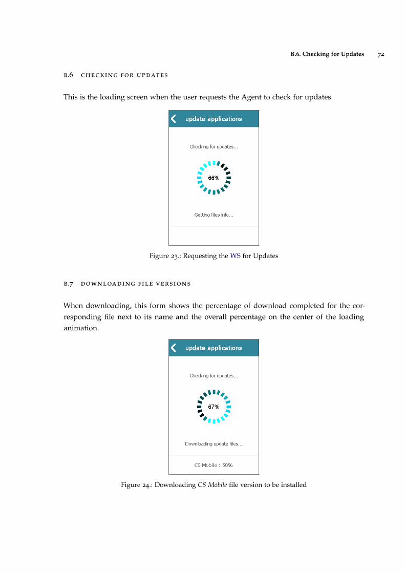
B.6. Checking for Updates 72
b.6 checking for updates
This is the loading screen when the user requests the Agent to check for updates.
Figure 23.: Requesting the WS for Updates
b.7 downloading file versions
When downloading, this form shows the percentage of download completed for the cor-responding file next to its name and the overall percentage on the center of the loadinganimation.
Figure 24.: Downloading CS Mobile file version to be installed