Embed Size (px)
Citation preview
F5-4
F5-5
F5-6
F5-7
F5-8
F5-9
F5-10

F5-11
6-1
CHAPTER VI WATER CONVEYANCE AND TREATMENT PLANT
6.1 Alternative Water Conveyance Routes Identified
6.1.1 General
In this Study, the following three waterway plans are examined1:
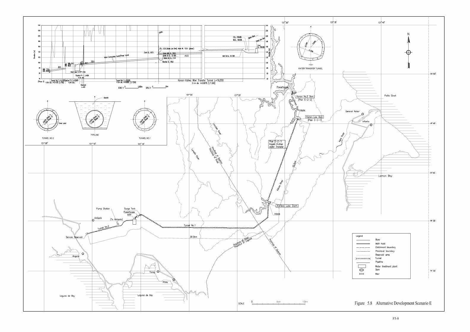
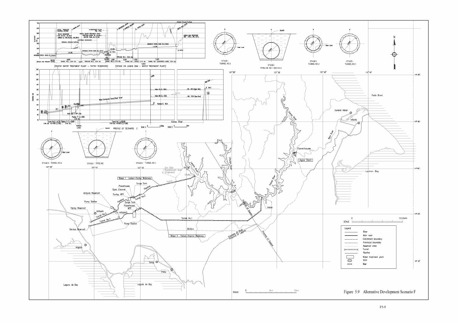
• Laiban-Taytay Waterway: Water Conveyance from Laiban High Dam to Taytay service reservoir (Scenario A and F)
• Laiban-Angono* Waterway: Water Conveyance from Laiban Low Dam to Angono service reservoir (Scenario H)
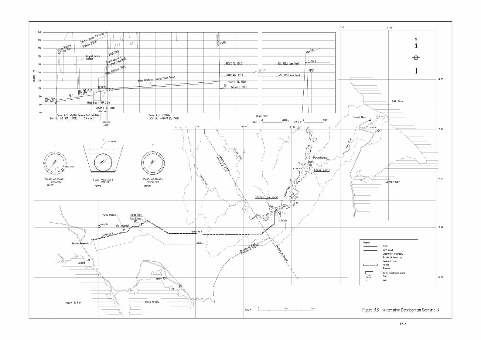
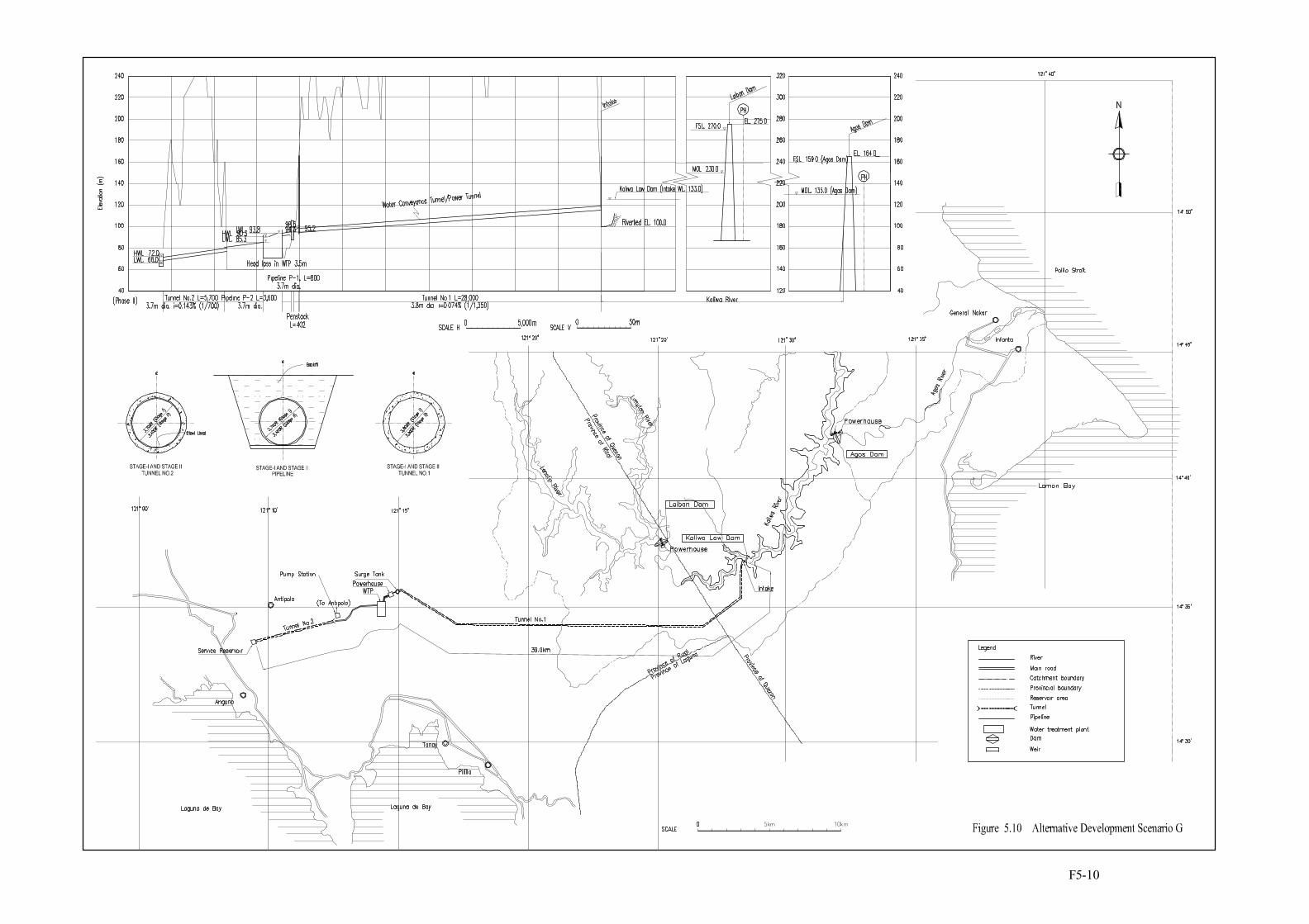
• Kaliwa-Angono* Waterway: Water Conveyance from Kaliwa Low Dam and/or Agos Dam to Angono service reservoir
(Scenario B to G)
Note: * Place of service reservoir. In F/S, the word of ‘Taytay’ is used. The location of reservoir is remains same.
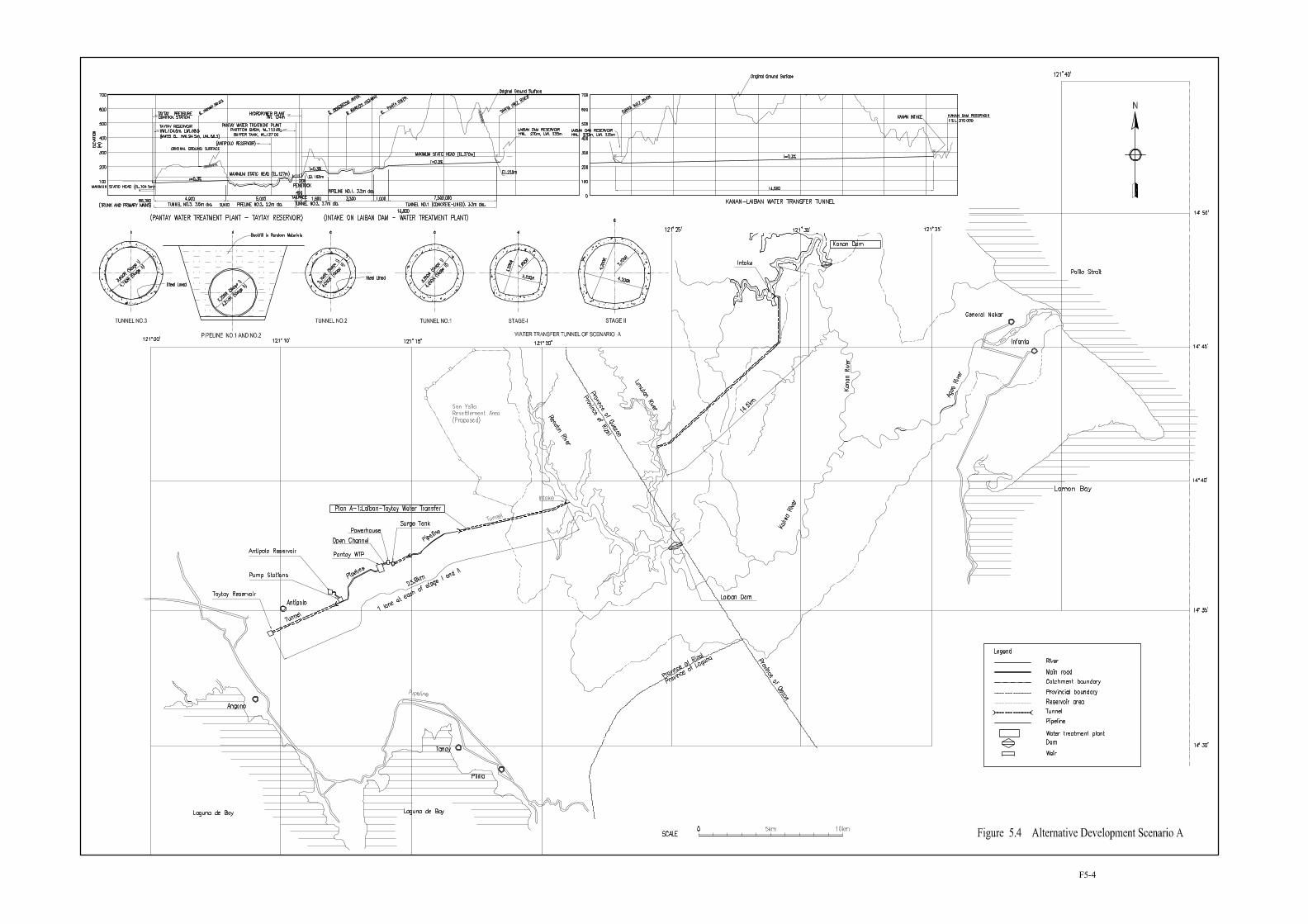
The general plan of the waterway route is shown in Figure 5.4 of Chapter V and also in the plans of respective Scenarios (Figure 5.4 to 5.11). Technical features of each water conveyance route are shown in Table 6.1.
6.1.2 Laiban-Taytay Water Conveyance Route for Laiban High Dam
Laiban-Taytay Water Conveyance Route was originally proposed in the feasibility study of MWSP III project in 1979 and later finalized in the Detailed Engineering Design of July 1984. Subsequently, the Review Study in 1979 revised the alignment of pipeline, pressure control station, pump station and service reservoirs. This study assumes the conveyance facilities to be as proposed in the latest Review Study.
6.1.3 Alternative Water Conveyance Routes for Kaliwa Low Dam and Agos Dam
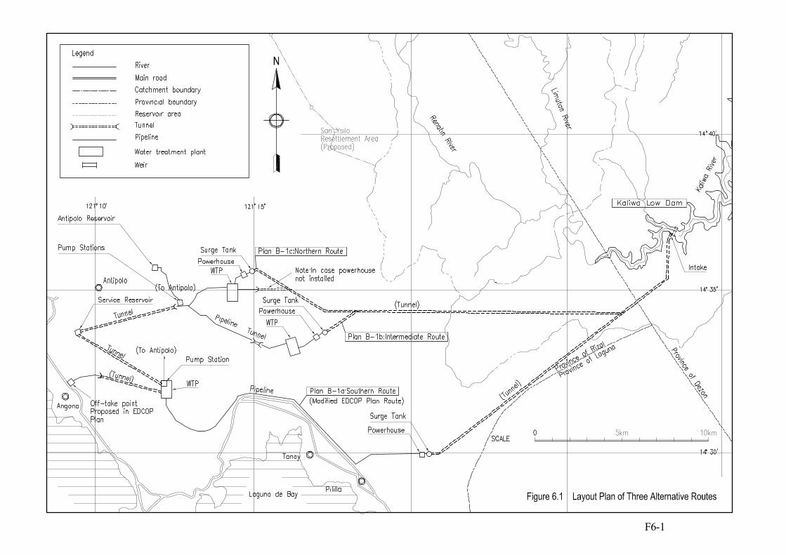
Three alternative routes of Kaliwa-Angono water conveyance routes were planned for comparison, namely Plan B-1a, Plan B-1b and Plan B-1c in the order from south to north. The plans were identified based on 1:50,000 topographic maps, 1:15,000 aerial photographs and findings from field reconnaissance survey. The general plan of the three alternative waterway routes is shown in Figure 6.1.
i) Plan B-1a (Southern Route): Identical to the route proposed in the EDCOP Study in 2001. Water taken at Kaliwa Low Dam is conveyed to a water treatment plant located some 4.5 km northwest from the town of Mabato through a pipeline to be laid out along the existing National Highway near
1 The definite location and route of waterway facilities were finally determined in the feasibility study stage due to the reasons of topographic and geological conditions observed at the sites, and new findings during the second field investigation. The final waterway route is shown in Figure 7.1 of Chapter 7 of Volume IV, Main Report of Feasibility Study.
6-2
the south coast of Laguna de Bay. The water treatment plant proposed by EDOCOP is located at a relatively low level of EL.40 m and water delivered to the distributors at an off-take point at EL.10 m. For comparison with other alternative routes on an equal basis, it is planned in this Study that water is pumped up to Angono Service Reservoir at EL.72 m.
ii) Plan B-1b (Intermediate Route): The water is conveyed by a longer tunnel (24 km) which has the same route of Plan B-1a in the first 6 km section from the intake, then turns to the west. The water is conveyed to a water treatment plant at El. 105 m near Kalan Batu, located some 4.0 km north from the town of Baras. Treated water is further conveyed to Angono Service Reservoir by gravity through a pipeline and a tunnel.
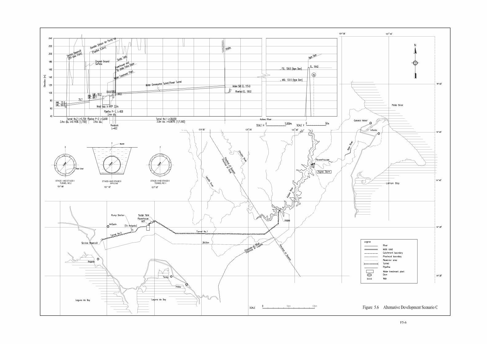
iii) Plan B-1c (Northern Route): The plan consists of a further longer tunnel (28 km) with a water treatment plant at EL. 95 m, located near Abuyod. Treated water is conveyed to Angono Service Reservoir by gravity.
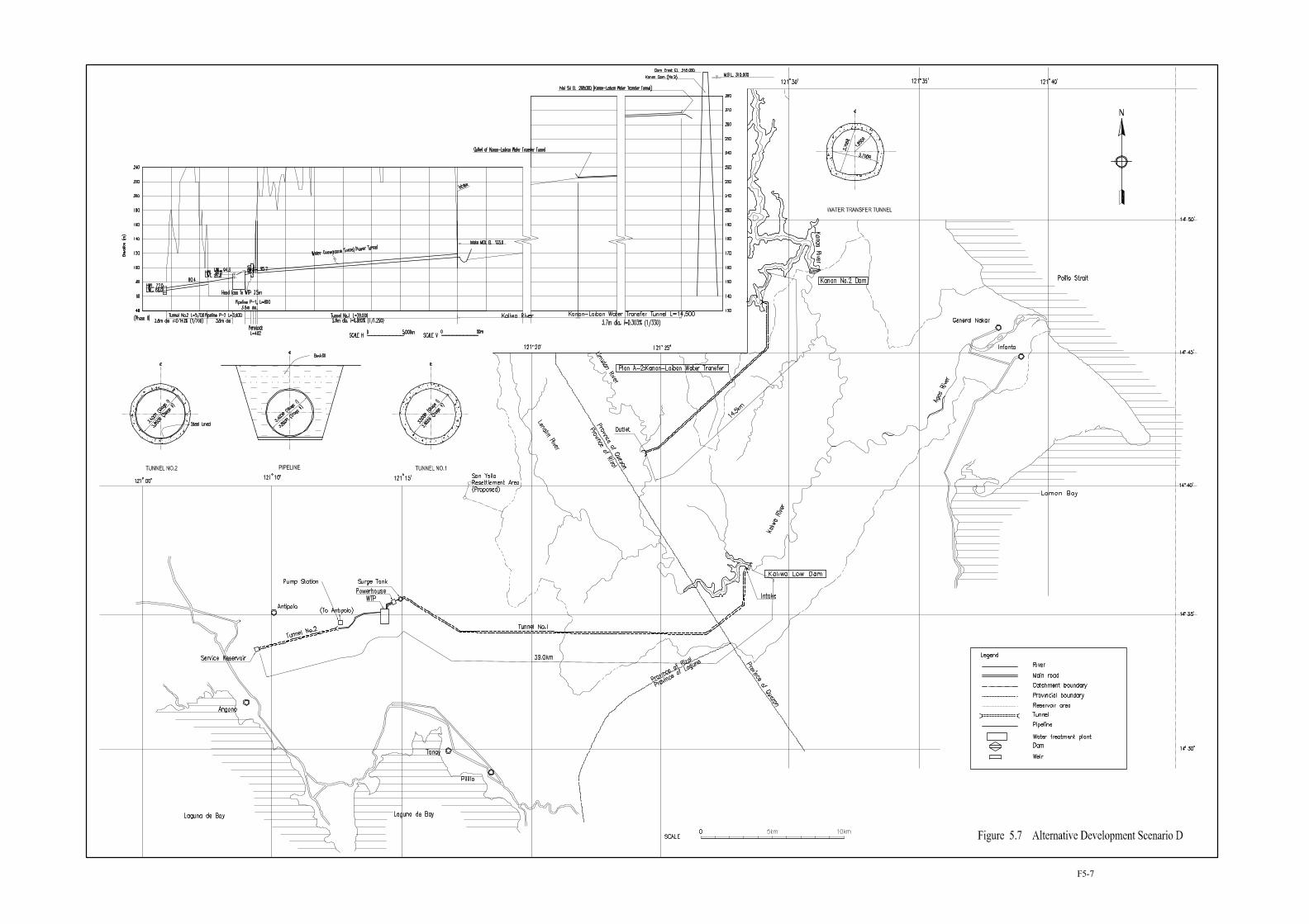
6.1.4 Laiban-Angono Water Conveyance Route for Laiban Low Dam
In the case of the Laiban-Angono waterway, water taken at Laiban Low Dam is conveyed to a water treatment plant at Kalan Batu (at the same location as for the plant for Plan B-1b above) through a 14 km long tunnel and a short pipeline. Thereafter, the waterway takes the same route as for the Plan B-1b.
6.2 Selection of Least Costly Route for the Kaliwa-Angono Waterway
A cost comparison study was made to find the least costly route for the Kaliwa-Angono waterway out of the three alternative routes proposed in Subsection 6.1.3. The layout plan of the three alternative routes is shown in Figure 6.1 and their profiles are shown in Figures E3.3 to E3.5 contained in Part-E of Volume III, respectively. Technical features of the three routes are described in Table 6.2. Each route has some technical problems to be solved by proper design of the facilities. The result of cost comparison is shown in Table 6.3 and summarized below:
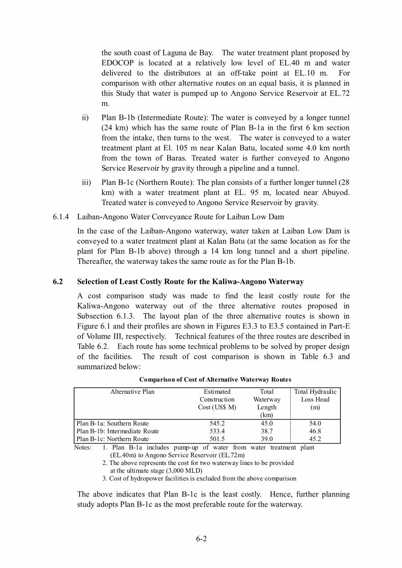
Comparison of Cost of Alternative Waterway Routes
Alternative Plan Estimated Construction
Cost (US$ M)
Total Waterway
Length (km)
Total Hydraulic Loss Head
(m)
Plan B-1a: Southern Route Plan B-1b: Intermediate Route Plan B-1c: Northern Route
545.2533.4501.5
45.038.739.0
54.046.845.2
Notes: 1. Plan B-1a includes pump-up of water from water treatment plant (EL.40m) to Angono Service Reservoir (EL.72m)
2. The above represents the cost for two waterway lines to be provided at the ultimate stage (3,000 MLD)
3. Cost of hydropower facilities is excluded from the above comparison
The above indicates that Plan B-1c is the least costly. Hence, further planning study adopts Plan B-1c as the most preferable route for the waterway.
6-3
Adit-1Adit-2
Adit-3
TBM 1
NATM 1NATM 2
TBM 2
TBM 3
NATM 3
NATM 4
WTP
Service reservoir
Power station
Intake
Water supplyfor Antipoloaera
Owing to limited head available between the Agos MOL (EL.133 m) and Angono Service Reservoir (EL.72 m), the waterway diameter has to be slightly larger than the case of the Laiban-Taytay waterway for Laiban Dam.
6.3 Water Conveyance Facilities and Treatment Plant for Selected Kaliwa-Angono Water Conveyance Route
6.3.1 Water Conveyance Facilities
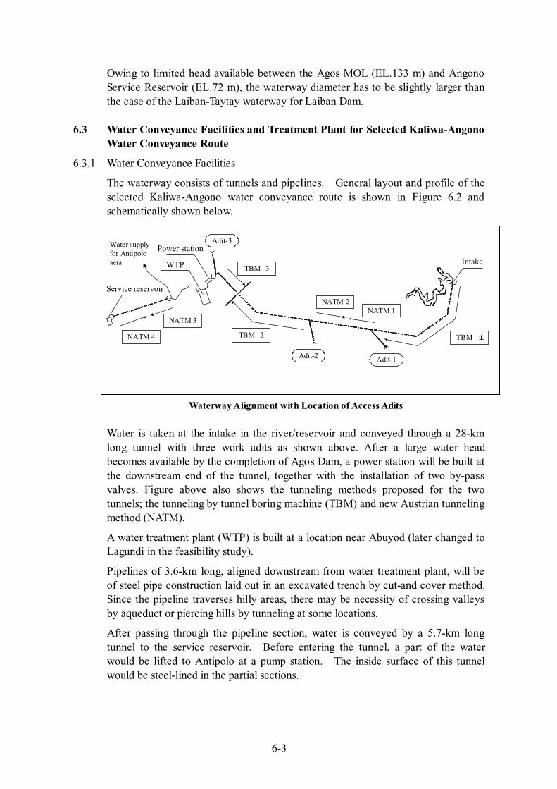
The waterway consists of tunnels and pipelines. General layout and profile of the selected Kaliwa-Angono water conveyance route is shown in Figure 6.2 and schematically shown below.
Waterway Alignment with Location of Access Adits
Water is taken at the intake in the river/reservoir and conveyed through a 28-km long tunnel with three work adits as shown above. After a large water head becomes available by the completion of Agos Dam, a power station will be built at the downstream end of the tunnel, together with the installation of two by-pass valves. Figure above also shows the tunneling methods proposed for the two tunnels; the tunneling by tunnel boring machine (TBM) and new Austrian tunneling method (NATM).
A water treatment plant (WTP) is built at a location near Abuyod (later changed to Lagundi in the feasibility study).
Pipelines of 3.6-km long, aligned downstream from water treatment plant, will be of steel pipe construction laid out in an excavated trench by cut-and cover method. Since the pipeline traverses hilly areas, there may be necessity of crossing valleys by aqueduct or piercing hills by tunneling at some locations.
After passing through the pipeline section, water is conveyed by a 5.7-km long tunnel to the service reservoir. Before entering the tunnel, a part of the water would be lifted to Antipolo at a pump station. The inside surface of this tunnel would be steel-lined in the partial sections.
6-4
6.3.2 Hydraulic Conditions
Two water conveyance tunnels are provided at the ultimate stage. The first tunnel will be constructed under the Kaliwa Low Dam scheme in the first stage and the second tunnel with the Agos dam in the second stage. The capacity of tunnels is 1.21 times the average yield: i.e. 3,640 MLD (3,000 MLDx1.21) or 42.0 m3/sec by two tunnels.
The tunnel and pipeline size will be determined to meet the required design discharge capacity mentioned above. Then, the hydraulic longitudinal profile of waterway, including the water levels at the proposed structures (e.g. water treatment plant, powerhouse), was determined based on hydraulic loss head calculation. The head loss due to friction in the tunnel and pipeline was calculated by William-Hazen formula.
The design water level of the Angono service reservoir is set at EL. 72 m, which represents the required water level ensuring the distribution of water to the service areas by gravity. Therefore, water level at Angono service reservoir is set as the starting point for designing the hydraulic profile of the waterway.
As the result of calculation, the head loss due to friction and other losses was calculated at 12.2 m between the Angono service reservoir and water treatment plant (L=9,300), and at 1.1 m between the water treatment plant and power station/valve house (L = 800 m).
6.3.3 Water Treatment Facility
(1) Proposed Site
Water treatment plant site was selected by examining 1:50,000 map and aerial photographs and conducting a field visit to the site. The proposed site is situated in the municipality of Teresa, about 3 km east of Antipolo near the provincial road connecting Riza and Antipolo.
The elevation of the area ranges from EL. 90-100 m in the relatively flat areas to EL. 120 m on the hilltops, generally descending gently to the south. Construction of the plant yard will require several millions m3 of earth works.
(2) Design Principles
(a) Design capacity
Water treatment plant should be designed to have a capacity capable of meeting the daily water demand. Water use within the yard of treatment plant site and unpredictable losses should be as minimal as possible from the viewpoint of saving raw waters as well as from the environmental aspect. Wash water from the filters is returned to receiving well, and sludge from sedimentation basin is thickened and supernatant water also returned to receiving well through filter wash water storage.
At this study stage, the nominal plant capacity is planned to be equivalent to the maximum daily water demand.
6-5
(b) Type of treatment facility
The treatment process units are designed taking account of raw water quality (see Subsection 3.3), construction cost and O&M aspect. Simple structures will bring flexibility to the variation of raw water quality and unpredictable constraints on O&M works. In this context, the coagulation-sedimentation and rapid sand filtration method will be used for the proposed WTP, the same as the existing WTPs.
(2) Preliminary Design of Major Facilities
Preliminary design of major plant facilities is prepared following the design criteria of the American Waterworks Association (AWWA) and/or the Japan Waterworks Association (JWWA) with due consideration of functionally appropriate layout and environmental aspects.
The concept of preparing the design is described in Part-F of Volume III. The design was finally elaborated in the feasibility study, which is presented in the Figures contained in Volume IV.
6.3.4 Treated Water Conveyance and Delivery Facilities
(1) Basic Concept of Planning
In planning the water conveyance and delivery facilities, the Study set out the following basic planning concepts:
(a) Main service area of the proposed Project is planned to be the southwestern part (Cavite area), southern part (Muntinlupa area) and southeastern part (towns in Rizal Province) of the MWSS supply area.
(b) The ground elevation of the proposed main service areas is assumed at EL. 5 - 50 m in NAMRIA datum (EL. 15-60 m in MWSS datum), to which the proposed Angono (Taytay) Service Reservoir with HWL 72m could deliver the water by gravity.
Note: Within the proposed main service areas, the area higher than the proposed take-off point is very limited, e.g. Susana Heights in Muntinlupa, about 7 km away from the proposed primary main to be installed between Alabang and Las Pinas. For water supply to such a specific subdivision, pumping system shall be provided. However, the water volume to be supplied is limited.
(c) The other part of main services areas of Metro Manila including those higher than E.L. 50 m (mostly in the northern part) are assumed to be supplied by the existing Angat water supply system. Water distribution in the supply network should be planned so as to minimize the pumping operation within the network with integrated operation of the Angat and Kaliwa-Agos systems.
(d) The Study contemplates the pump-up of water for the water conveyance to the Antipolo Service Reservoir. The water for Antipolo area is extracted at a pump station provided at the midway of pipeline between the water treatment plant and the Angono service reservoir. Although the pump-up of water leads to a higher water rate, there is no other choice than adopting the pumping system since Antipolo area is situated higher than EL.200m.
6-6
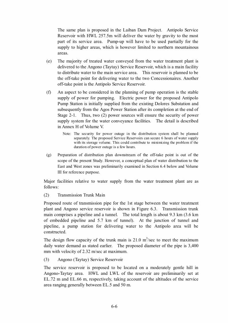
The same plan is proposed in the Laiban Dam Project. Antipolo Service Reservoir with HWL 257.5m will deliver the water by gravity to the most part of its service area. Pump-up will have to be used partially for the supply to higher areas, which is however limited to northern mountainous areas.
(e) The majority of treated water conveyed from the water treatment plant is delivered to the Angono (Taytay) Service Reservoir, which is a main facility to distribute water to the main service area. This reservoir is planned to be the off-take point for delivering water to the two Concessionaires. Another off-take point is the Antipolo Service Reservoir.
(f) An aspect to be considered in the planning of pump operation is the stable supply of power for pumping. Electric power for the proposed Antipolo Pump Station is initially supplied from the existing Dolores Substation and subsequently from the Agos Power Station after its completion at the end of Stage 2-1. Thus, two (2) power sources will ensure the security of power supply system for the water conveyance facilities. The detail is described in Annex H of Volume V.
Note: The security for power outage in the distribution system shall be planned separately. The proposed Service Reservoirs can secure 6 hours of water supply with its storage volume. This could contribute to minimizing the problem if the duration of power outage is a few hours.
(g) Preparation of distribution plan downstream of the off-take point is out of the scope of the present Study. However, a conceptual plan of water distribution to the East and West zones was preliminarily examined in Section 6.4 below and Volume III for reference purpose.
Major facilities relative to water supply from the water treatment plant are as follows:
(2) Transmission Trunk Main
Proposed route of transmission pipe for the 1st stage between the water treatment plant and Angono service reservoir is shown in Figure 6.3. Transmission trunk main comprises a pipeline and a tunnel. The total length is about 9.3 km (3.6 km of embedded pipeline and 5.7 km of tunnel). At the junction of tunnel and pipeline, a pump station for delivering water to the Antipolo area will be constructed.
The design flow capacity of the trunk main is 21.0 m3/sec to meet the maximum daily water demand as stated earlier. The proposed diameter of the pipe is 3,400 mm with velocity of 2.32 m/sec at maximum.
(3) Angono (Taytay) Service Reservoir
The service reservoir is proposed to be located on a moderately gentle hill in Angono-Taytay area. HWL and LWL of the reservoir are preliminarily set at EL.72 m and EL.66 m, respectively, taking account of the altitudes of the service area ranging generally between EL.5 and 50 m.
6-7
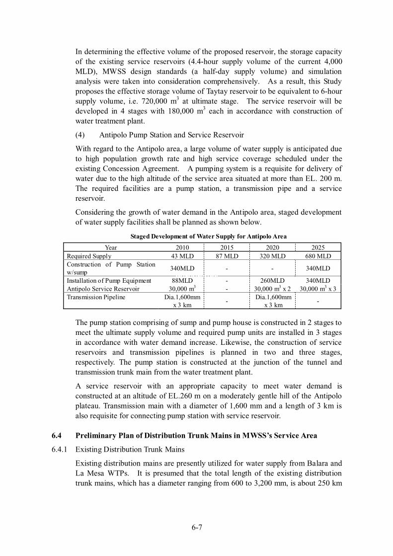
In determining the effective volume of the proposed reservoir, the storage capacity of the existing service reservoirs (4.4-hour supply volume of the current 4,000 MLD), MWSS design standards (a half-day supply volume) and simulation analysis were taken into consideration comprehensively. As a result, this Study proposes the effective storage volume of Taytay reservoir to be equivalent to 6-hour supply volume, i.e. 720,000 m3 at ultimate stage. The service reservoir will be developed in 4 stages with 180,000 m3 each in accordance with construction of water treatment plant.
(4) Antipolo Pump Station and Service Reservoir
With regard to the Antipolo area, a large volume of water supply is anticipated due to high population growth rate and high service coverage scheduled under the existing Concession Agreement. A pumping system is a requisite for delivery of water due to the high altitude of the service area situated at more than EL. 200 m. The required facilities are a pump station, a transmission pipe and a service reservoir.
Considering the growth of water demand in the Antipolo area, staged development of water supply facilities shall be planned as shown below.
Staged Development of Water Supply for Antipolo Area
Year 2010 2015 2020 2025 Required Supply 43 MLD 87 MLD 320 MLD 680 MLD Construction of Pump Station w/sump
340MLD - - 340MLD
Installation of Pump Equipment 88MLD - 260MLD 340MLD Antipolo Service Reservoir 30,000 m3 - 30,000 m3 x 2 30,000 m3 x 3 Transmission Pipeline Dia.1,600mm
x 3 km -
Dia.1,600mm x 3 km
-
The pump station comprising of sump and pump house is constructed in 2 stages to meet the ultimate supply volume and required pump units are installed in 3 stages in accordance with water demand increase. Likewise, the construction of service reservoirs and transmission pipelines is planned in two and three stages, respectively. The pump station is constructed at the junction of the tunnel and transmission trunk main from the water treatment plant.
A service reservoir with an appropriate capacity to meet water demand is constructed at an altitude of EL.260 m on a moderately gentle hill of the Antipolo plateau. Transmission main with a diameter of 1,600 mm and a length of 3 km is also requisite for connecting pump station with service reservoir.
6.4 Preliminary Plan of Distribution Trunk Mains in MWSS’s Service Area
6.4.1 Existing Distribution Trunk Mains
Existing distribution mains are presently utilized for water supply from Balara and La Mesa WTPs. It is presumed that the total length of the existing distribution trunk mains, which has a diameter ranging from 600 to 3,200 mm, is about 250 km

6-8
within the service area as of 1994. Figure 6.3 shows the network of the existing trunk mains.
Parts of the existing trunk mains are used for water supply from the new water treatment plant (WTP) that will be built under the proposed project. The existing trunk mains along EDSA and Ortigas Avenue are considered to form the boundary between the service areas supplied from the existing Balara WTP and the proposed new WTP.
6.4.2 Preliminary Plan of New Distribution Trunk Mains
The service area to be supplied from the proposed Angono (Taytay) Service Reservoir is planned to cover the southwestern part (Cavite area), southern part (Muntinlupa area) and southeastern part (Rizal towns) by gravity flow.
Although actual preparation of distribution plans is subject to the two (2) concessionaires, a preliminary plan of distribution primary mains was examined in the Study for reference. Figure 6.4 presents the staged installation of distribution trunk mains for the said service area together with other related facilities (water treatment plant, service reservoir, transmission main and required facilities for water supply to Antipolo area). The total length of distribution trunk mains is estimated to be about 155 km. Hydraulic analysis for the distribution system is contained in Part-F of Volume III. Actual distribution plan
(a) First stage to meet 910 MLD
A 4,000 mm diameter distribution trunk main from the proposed Angono (Taytay) service reservoir will be installed and bifurcated, at the junction of national and provincial road in the municipality of Taytay, into two trunk mains with a diameter of 3,400 mm each. The trunk mains will be installed along Taytay-Cainta-Pasig route and Taytay-Pateros-Taguig route to connect with the existing primary main at Pasig and Taguig. Further, to convey water to Muntinlupa and Cavite area, 2,800-3,000 mm primary mains willbe also required along Taguig-Paranaque-Las Pinas route. For farthest part of Cavite area, 600 to 1,000 mm of trunk mains will be installed to connect with the existing 1,300 mm at Bacoor. In addition, 3,200 mm of pipe is planned to augment the supply capacity of the existing primary main (diameter of 450 to 1,200 mm) supplying Pasig-Makati-Pasay area.
(b) Second stage to meet 1,820 MLD
In the 2nd stage, trunk mains of 900-2,200 mm diameter are planned at Makati-Pasay and Paranaque-Cavite areas to augment supply capacity meeting a total demand of 1,820 MLD in the service area.
(c) Final stage to meet 3,640 MLD
In the final stage, bulk water supply is planned for the southeastern part, such as Cardona-Moron-Baras-Tanay-Pililla and Jala-Jala, by extending the trunk mains with the diameter of 350 to 1,500 mm. To meet full development of water supply, additional trunk mains with the diameter of
6-9
3,400 to 4,000 mm are planned for the Taytay service reservoir-Taytay-Pasig route.
6.4.3 Preliminary Cost Estimate of New Distribution Trunk Mains
The required cost for new distribution trunk mains was estimated base on the following assumptions:
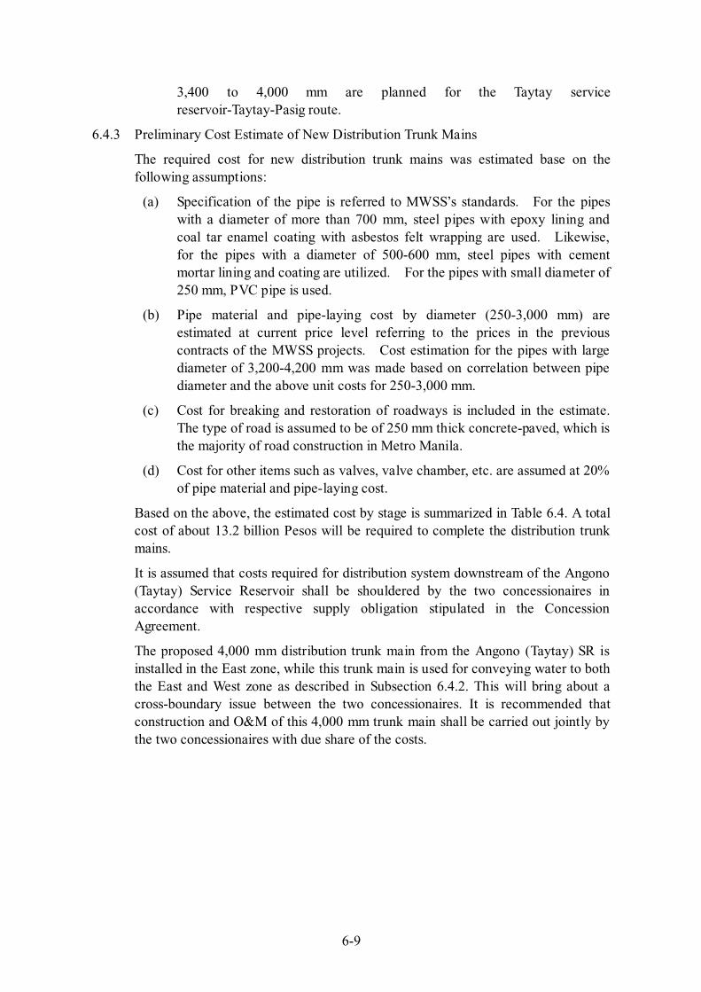
(a) Specification of the pipe is referred to MWSS’s standards. For the pipes with a diameter of more than 700 mm, steel pipes with epoxy lining and coal tar enamel coating with asbestos felt wrapping are used. Likewise, for the pipes with a diameter of 500-600 mm, steel pipes with cement mortar lining and coating are utilized. For the pipes with small diameter of 250 mm, PVC pipe is used.
(b) Pipe material and pipe-laying cost by diameter (250-3,000 mm) are estimated at current price level referring to the prices in the previous contracts of the MWSS projects. Cost estimation for the pipes with large diameter of 3,200-4,200 mm was made based on correlation between pipe diameter and the above unit costs for 250-3,000 mm.
(c) Cost for breaking and restoration of roadways is included in the estimate. The type of road is assumed to be of 250 mm thick concrete-paved, which is the majority of road construction in Metro Manila.
(d) Cost for other items such as valves, valve chamber, etc. are assumed at 20% of pipe material and pipe-laying cost.
Based on the above, the estimated cost by stage is summarized in Table 6.4. A total cost of about 13.2 billion Pesos will be required to complete the distribution trunk mains.
It is assumed that costs required for distribution system downstream of the Angono (Taytay) Service Reservoir shall be shouldered by the two concessionaires in accordance with respective supply obligation stipulated in the Concession Agreement.
The proposed 4,000 mm distribution trunk main from the Angono (Taytay) SR is installed in the East zone, while this trunk main is used for conveying water to both the East and West zone as described in Subsection 6.4.2. This will bring about a cross-boundary issue between the two concessionaires. It is recommended that construction and O&M of this 4,000 mm trunk main shall be carried out jointly by the two concessionaires with due share of the costs.
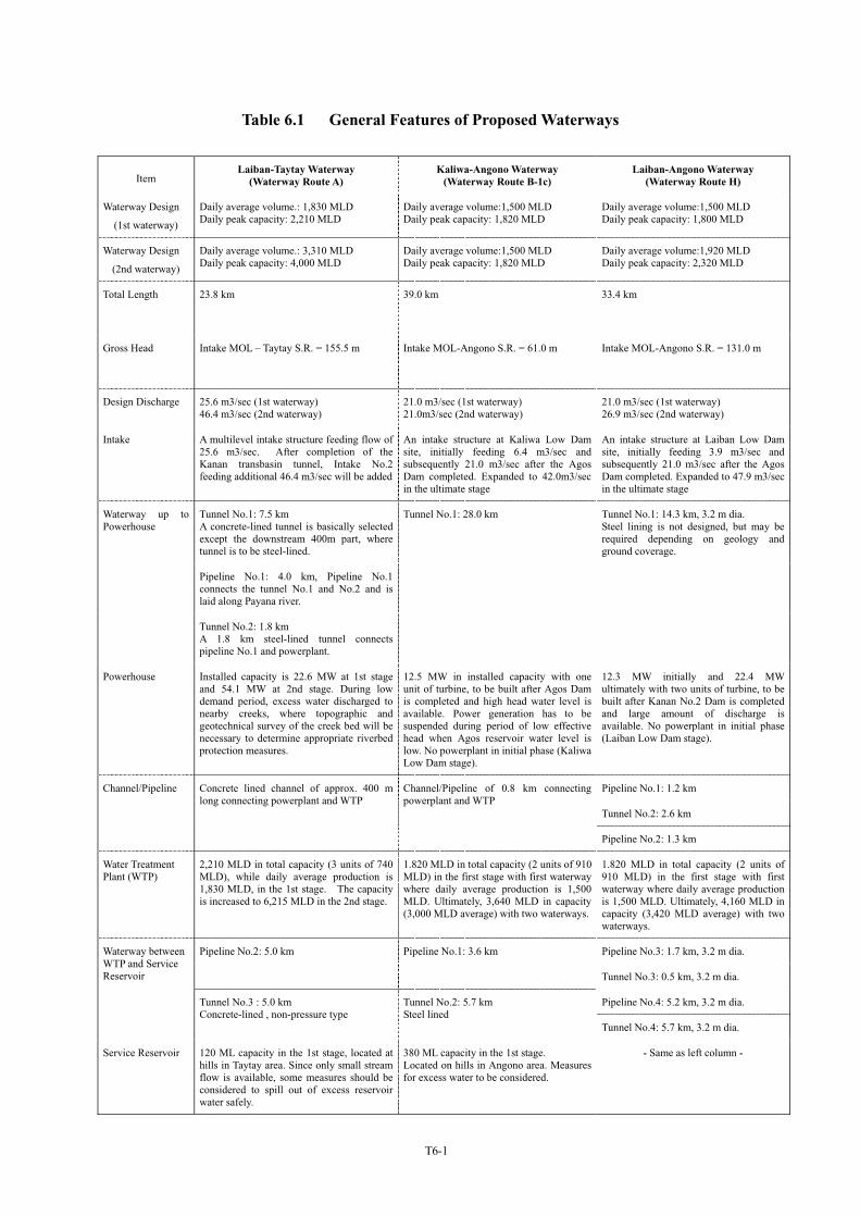
Table 6.1 General Features of Proposed Waterways
ItemLaiban-Taytay Waterway
(Waterway Route A)Kaliwa-Angono Waterway
(Waterway Route B-1c)Laiban-Angono Waterway
(Waterway Route H)
Waterway Design
(1st waterway)
Daily average volume.: 1,830 MLD Daily peak capacity: 2,210 MLD
Daily average volume:1,500 MLD Daily peak capacity: 1,820 MLD
Daily average volume:1,500 MLD Daily peak capacity: 1,800 MLD
Waterway Design
(2nd waterway)
Daily average volume.: 3,310 MLD Daily peak capacity: 4,000 MLD
Daily average volume:1,500 MLD Daily peak capacity: 1,820 MLD
Daily average volume:1,920 MLD Daily peak capacity: 2,320 MLD
Total Length 23.8 km 39.0 km 33.4 km
Gross Head Intake MOL – Taytay S.R. = 155.5 m Intake MOL-Angono S.R. = 61.0 m Intake MOL-Angono S.R. = 131.0 m
Design Discharge 25.6 m3/sec (1st waterway) 46.4 m3/sec (2nd waterway)
21.0 m3/sec (1st waterway) 21.0m3/sec (2nd waterway)
21.0 m3/sec (1st waterway) 26.9 m3/sec (2nd waterway)
Intake A multilevel intake structure feeding flow of 25.6 m3/sec. After completion of the Kanan transbasin tunnel, Intake No.2 feeding additional 46.4 m3/sec will be added
An intake structure at Kaliwa Low Dam site, initially feeding 6.4 m3/sec and subsequently 21.0 m3/sec after the Agos Dam completed. Expanded to 42.0m3/sec in the ultimate stage
An intake structure at Laiban Low Dam site, initially feeding 3.9 m3/sec and subsequently 21.0 m3/sec after the Agos Dam completed. Expanded to 47.9 m3/sec in the ultimate stage
Tunnel No.1: 7.5 km A concrete-lined tunnel is basically selected except the downstream 400m part, where tunnel is to be steel-lined.
Pipeline No.1: 4.0 km, Pipeline No.1 connects the tunnel No.1 and No.2 and is laid along Payana river.
Waterway up to Powerhouse
Tunnel No.2: 1.8 km A 1.8 km steel-lined tunnel connects pipeline No.1 and powerplant.
Tunnel No.1: 28.0 km Tunnel No.1: 14.3 km, 3.2 m dia. Steel lining is not designed, but may be required depending on geology and ground coverage.
Powerhouse Installed capacity is 22.6 MW at 1st stage and 54.1 MW at 2nd stage. During low demand period, excess water discharged to nearby creeks, where topographic and geotechnical survey of the creek bed will be necessary to determine appropriate riverbed protection measures.
12.5 MW in installed capacity with one unit of turbine, to be built after Agos Dam is completed and high head water level is available. Power generation has to be suspended during period of low effective head when Agos reservoir water level is low. No powerplant in initial phase (Kaliwa Low Dam stage).
12.3 MW initially and 22.4 MW ultimately with two units of turbine, to be built after Kanan No.2 Dam is completed and large amount of discharge is available. No powerplant in initial phase (Laiban Low Dam stage).
Pipeline No.1: 1.2 km
Tunnel No.2: 2.6 km
Channel/Pipeline Concrete lined channel of approx. 400 m long connecting powerplant and WTP
Channel/Pipeline of 0.8 km connecting powerplant and WTP
Pipeline No.2: 1.3 km
Water Treatment Plant (WTP)
2,210 MLD in total capacity (3 units of 740 MLD), while daily average production is 1,830 MLD, in the 1st stage. The capacity is increased to 6,215 MLD in the 2nd stage.
1.820 MLD in total capacity (2 units of 910 MLD) in the first stage with first waterway where daily average production is 1,500 MLD. Ultimately, 3,640 MLD in capacity (3,000 MLD average) with two waterways.
1.820 MLD in total capacity (2 units of 910 MLD) in the first stage with first waterway where daily average production is 1,500 MLD. Ultimately, 4,160 MLD in capacity (3,420 MLD average) with two waterways.
Pipeline No.3: 1.7 km, 3.2 m dia.Pipeline No.2: 5.0 km Pipeline No.1: 3.6 km
Tunnel No.3: 0.5 km, 3.2 m dia.
Pipeline No.4: 5.2 km, 3.2 m dia.
Waterway between WTP and Service Reservoir
Tunnel No.3 : 5.0 km Concrete-lined , non-pressure type
Tunnel No.2: 5.7 km Steel lined
Tunnel No.4: 5.7 km, 3.2 m dia.
Service Reservoir 120 ML capacity in the 1st stage, located at hills in Taytay area. Since only small stream flow is available, some measures should be considered to spill out of excess reservoir water safely.
380 ML capacity in the 1st stage. Located on hills in Angono area. Measures for excess water to be considered.
- Same as left column -
T6-1
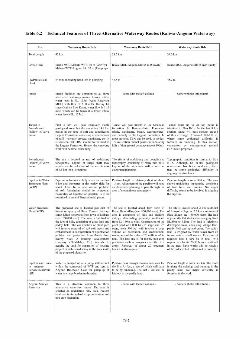
Table 6.2 Technical Features of Three Alternative Waterway Routes (Kaliwa-Angono Waterway)
Item Waterway Route B-1a Waterway Route B-1b Waterway Route B-1c
Total Length 45 km 38.5 km 39.0 km
Gross Head Intake MOL-Mabato WTP: 90 m (Gravity) Mabato WTP-Angono SR: 32 m (Pump up)
Intake MOL-Angono SR: 65 m (Gravity) Intake MOL-Angono SR: 65 m (Gravity)
Hydraulic Loss Head
54.0 m, including head loss in pumping 46.8 m 45.2 m
Intake Intake facilities are common to all three alternative waterway routes. Lowest intake water level is EL. 133m (Agos Reservoir MOL) with flow of 21.0 m3/s. During 1st stage (Kaliwa Low Dam), water flow is 11.9 m3/s which can be taken at a lower intake water level (EL. 125m)
- Same with the left column - - Same with the left column -
Tunnel to Powerhouse/ Hollow-jet Valve house
First 5 km will pass relatively stable geological zone, but the remaining 14.8 km passes in the zone of soft and complicated Laguna Formation, consisting of alternations of tuffs, volcanic breccia, sandstone, etc. It is foreseen that TBM should not be used in the Laguna Formation. Hence, the tunneling work will be time-consuming.
Tunnel will pass mostly in the Kinabuan formation & Barenas-Baito Formation (shale, sandstone, basalt, aggromerates) and partially in the Laguna Formation. In most sections, TBM can be used. In the last 3.5 km section, tunnel passes in undulating hills of thin ground coverage (about 100m).
Tunnel route up to 21 km point is identical to Plan B-1b. In the last 8 km section, tunnel will pass through ground of thin coverage of around 100-150 m, where some geological difficulty is foreseen in tunneling. In this section, excavation by conventional method (NATM) is proposed.
Powerhouse/ Hollow-jet Valve house
The site is located in area of undulating topography. Layout of surge shaft may require careful selection of the site. Access of 4.5 km long is required.
The site is of undulating and complicated topography, consisting of many thin hills. Layout of the structures will require an elaborated planning.
Topographic condition is similar to Plan B-1b. Although no in-situ geological observation has been conducted, there may be some geological difficulty in aligning the structures.
Pipeline to Water Treatment Plant (WTP)
Pipeline is laid out in hilly areas for the first 4 km and thereafter in flat paddy field for about 14 km. In the latter section, problem of soft foundation should be overcome. Possibility of liquefaction problem is to be examined in area of Baras alluvial plains.
Pipeline length is relatively short of about 1.3 km. Alignment of the pipeline will need an elaborated planning to pass through the area of mountainous topography.
Pipeline length is some 800 m. The area shows undulating topography consisting of low hills and creeks. No major difficulty seems to be involved in aligning the pipeline.
Water Treatment Plant (WTP)
The proposed site is located just east of limestone quarry of Rizal Cement Factory, some 4.5km northwest from town of Mabato (see 1/50,000 map). The area is flat land at the foot of hills, consisting of grass land and paddy field. The construction of plant yard will involve removal of soft soil layers and embankment in consideration of liquefaction problem and protection from floods from nearby river. A housing development company (Phil-Malay Co.) intends to acquire the land for expansion of housing project, which is underway in the area south of the proposed plant site.
The site is located about 1km north of Kalan Batu village(see 1/50,000 map). The area is composed of hills and shallow valleys, descending generally southward from EL.140m to 60m. Construction of the plant yard of 1,000 ha (1st stage and 2nd
stage, each 500 ha) will involve a large volume of excavation and embankment works, say, of the order of 20 million m3 in total. The land use is for mostly tree crop plantation such as mangoes and other tree crops. Removal of about 20 tenement houses is also required.
The site is located about 2 km southeast of Abuyod village or 2.5 km southwest of Riza village (see 1/50,000 map). The land is generally flat at elevations ranging from EL.80m to 120m. The land is relatively developed areas, consisting village land, paddy field and upland crops. The paddy land is irrigated by water taken from an intake weir at small stream. Provision of required land (1,000 ha in total) will require to relocate 20-30 houses scattered in the area. Earth works will be roughly of the order of 6-7 million m3 in quantity.
Pipeline and Tunnel to Angono Service Reservoir (SR)
Water is pumped up at a pump station built within the compound of WTP and sent to Angono Reservoir. Cost for pump-up of water is a large burden in this plan.
Pipeline pass through mountainous area for the first 4.4 km, a part of which will have to be by tunneling. The last 3 km will be laid out in the paddy land .
Pipeline length is some 3.6 km. The route is along the existing road running in the paddy land. No major difficulty is foreseen in the work.
Angono Service Reservoir
This is a structure common to three alternative waterway routes. The area is situated on undulating hilly area. Present land use is for upland crop cultivation and tree crop plantation.
- Same with the left column - - Same with the left column -
T6-2
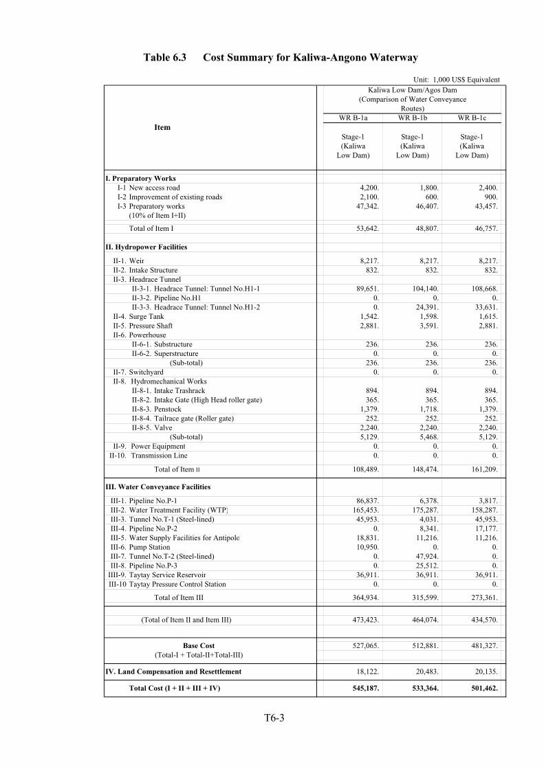
Table 6.3 Cost Summary for Kaliwa-Angono Waterway
Unit: 1,000 US$ EquivalentKaliwa Low Dam/Agos Dam
(Comparison of Water ConveyanceRoutes)
WR B-1a WR B-1b WR B-1cItem
Stage-1 Stage-1 Stage-1(Kaliwa (Kaliwa (Kaliwa
Low Dam) Low Dam) Low Dam)
I. Preparatory WorksI-1 New access road 4,200. 1,800. 2,400. I-2 Improvement of existing roads 2,100. 600. 900. I-3 Preparatory works 47,342. 46,407. 43,457.
(10% of Item I+II)
Total of Item I 53,642. 48,807. 46,757.
II. Hydropower Facilities
II-1. Weir 8,217. 8,217. 8,217. II-2. Intake Structure 832. 832. 832. II-3. Headrace Tunnel
II-3-1. Headrace Tunnel: Tunnel No.H1-1 89,651. 104,140. 108,668. II-3-2. Pipeline No.H1 0. 0. 0. II-3-3. Headrace Tunnel: Tunnel No.H1-2 0. 24,391. 33,631.
II-4. Surge Tank 1,542. 1,598. 1,615. II-5. Pressure Shaft 2,881. 3,591. 2,881. II-6. Powerhouse
II-6-1. Substructure 236. 236. 236. II-6-2. Superstructure 0. 0. 0.
(Sub-total) 236. 236. 236. II-7. Switchyard 0. 0. 0. II-8. Hydromechanical Works
II-8-1. Intake Trashrack 894. 894. 894. II-8-2. Intake Gate (High Head roller gate) 365. 365. 365. II-8-3. Penstock 1,379. 1,718. 1,379. II-8-4. Tailrace gate (Roller gate) 252. 252. 252. II-8-5. Valve 2,240. 2,240. 2,240.
(Sub-total) 5,129. 5,468. 5,129. II-9. Power Equipment 0. 0. 0.
II-10. Transmission Line 0. 0. 0.
Total of Item II 108,489. 148,474. 161,209.
III. Water Conveyance Facilities
III-1. Pipeline No.P-1 86,837. 6,378. 3,817. III-2. Water Treatment Facility (WTP) 165,453. 175,287. 158,287. III-3. Tunnel No.T-1 (Steel-lined) 45,953. 4,031. 45,953. III-4. Pipeline No.P-2 0. 8,341. 17,177. III-5. Water Supply Facilities for Antipolo 18,831. 11,216. 11,216. III-6. Pump Station 10,950. 0. 0. III-7. Tunnel No.T-2 (Steel-lined) 0. 47,924. 0. III-8. Pipeline No.P-3 0. 25,512. 0.
IIII-9. Taytay Service Reservoir 36,911. 36,911. 36,911. III-10 Taytay Pressure Control Station 0. 0. 0.
Total of Item III 364,934. 315,599. 273,361.
Base Cost(Total of Item II and Item III) 473,423. 464,074. 434,570.
Base Cost 527,065. 512,881. 481,327. (Total-I + Total-II+Total-III)
IV. Land Compensation and Resettlement 18,122. 20,483. 20,135.
Total Cost (I + II + III + IV) 545,187. 533,364. 501,462.
T6-3
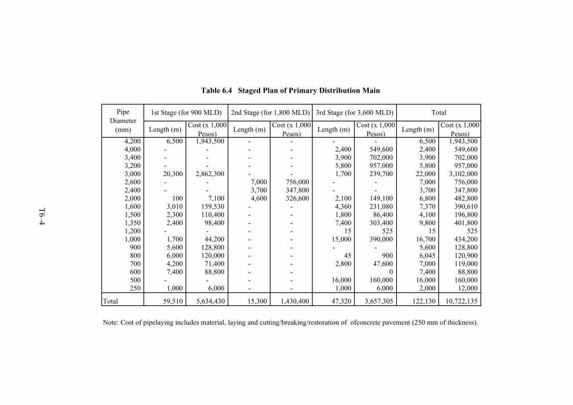
Length (m)Cost (x 1,000
Pesos)Length (m)
Cost (x 1,000Pesos)
Length (m)Cost (x 1,000
Pesos)Length (m)
Cost (x 1,000Pesos)
4,200 6,500 1,943,500 - - - - 6,500 1,943,5004,000 - - - - 2,400 549,600 2,400 549,6003,400 - - - - 3,900 702,000 3,900 702,0003,200 - - - - 5,800 957,000 5,800 957,0003,000 20,300 2,862,300 - - 1,700 239,700 22,000 3,102,0002,600 - - 7,000 756,000 - - 7,000 756,0002,400 - - 3,700 347,800 - - 3,700 347,8002,000 100 7,100 4,600 326,600 2,100 149,100 6,800 482,8001,600 3,010 159,530 - - 4,360 231,080 7,370 390,6101,500 2,300 110,400 - - 1,800 86,400 4,100 196,8001,350 2,400 98,400 - - 7,400 303,400 9,800 401,8001,200 - - - - 15 525 15 5251,000 1,700 44,200 - - 15,000 390,000 16,700 434,200
900 5,600 128,800 - - - - 5,600 128,800800 6,000 120,000 - - 45 900 6,045 120,900700 4,200 71,400 - - 2,800 47,600 7,000 119,000600 7,400 88,800 - - 0 7,400 88,800500 - - - - 16,000 160,000 16,000 160,000250 1,000 6,000 - - 1,000 6,000 2,000 12,000
Total 59,510 5,634,430 15,300 1,430,400 47,320 3,657,305 122,130 10,722,135
Note: Cost of pipelaying includes material, laying and cutting/breaking/restoration of ofconcrete pavement (250 mm of thickness).
Table 6.4 Staged Plan of Primary Distribution Main
PipeDiameter
(mm)
1st Stage (for 900 MLD) 2nd Stage (for 1,800 MLD) 3rd Stage (for 3,600 MLD) Total
T6–4
F6-1