Embed Size (px)
DESCRIPTION
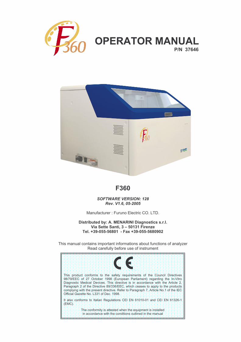
Biochemical Analyzer F360
Citation preview
����� ������ �� ������ ��� ���� ������� �������� ��� ��� ���� �� ���� �������������������� ��� ��� �������� ���� !������ � "������� �#� ��$��� $� ���� % &'�������$ ������ (������ �������)� ����� ��������� ��� � � ������ ��� *���� ���� +������� �,"���$���������� �����������������--.����,�*��������������������� ��� ����������������� $�*������������� ����������)�/��������"���$������,�+�������0�) ��������%�����������1�2�����0�)�3-- �������)� ���)
%�� ����� �� ������ ��� %����� � /�$����� �� ��%� �0� . 4 4&4 � � � ��%� �0� . -�.& !�(�#)
������ �������������������*�� ����������� ������ ������� ������� ���*���������� ���� ������ ��� ������� ��
����������������� ����
� ��
�������������� ���
���������������
(� ��������5�6� �������������)�3��)
���������������������������� !"#���$������%�&� �'�����' "��(� �)�*�+ +�����",�
��%��- ./�**/*�0�+��/�� 1�- ./�**/*�0�.�2
������� ����� ��� ��������� ��� �������� �������� ���� ������ ���2��/�������������������������� ����� �

SECTION 1 Version 1.6 Rev May 2005
FOREWORD .................................................................................. 11
SECTION 1. SAFETY PRECAUTIONS AND INSTALLATION ..12
1.1 WARNING SYMBOLS .............................................................................13
1.2 WARNING LABELS ................................................................................14
1.3 WARNINGS FOR SAFE USE ..................................................................16
1.4 SAFETY PRECAUTIONS ........................................................................17
1.5 INSTALLATION REQUIREMENTS .........................................................20
1.6 TECHNICAL SPECIFICATIONS .............................................................22
1.7 SYSTEM CONFIGURATION AND EQUIPMENT LIST ...........................27
1.8 EQUIPMENT LIST ...................................................................................28
SECTION 2. SYSTEM OVERVIEW ............................................31
2.1 ANALYSER OVERVIEW .........................................................................322.1.1 REAGENT MANAGEMENT (RCU scan) ....................................................................... 332.1.2 PREPARATION .......................................................................................................... 332.1.3 FIRST REAGENT MEASUREMENT .............................................................................. 342.1.4 SECOND REAGENT MEASUREMENT ......................................................................... 352.1.5 WASH .......................................................................................................... 352.1.6 EMERGENCY STOP ..................................................................................................... 352.1.7 AUTOMATIC RERUN .................................................................................................... 362.1.8 REAGENT BLANK MEASUREMENT ........................................................................... 362.1.9 WATER BLANK MEASUREMENT (Cuvette Check) ...................................................... 362.1.10 ISE MEASUREMENT ..................................................................................................... 36
2.2 SYSTEM COMPONENTS ........................................................................372.2.1 AUTOSAMPLER UNIT (ASP) ........................................................................................ 37
2.2.1.1 Turntable ......................................................................................................... 382.2.1.2 Barcode reader ................................................................................................ 38
2.2.2 REAGENT CONTAINER UNIT (RCU) ........................................................................... 392.2.2.1 Reagent bottles .............................................................................................. 392.2.2.2 Reagent Tray .................................................................................................. 402.2.2.3 Cooler .............................................................................................................. 41
2.2.3 SAMPLE PIPETTE UNIT (SPT) .................................................................................... 412.2.3.1 Level sensor..................................................................................................... 412.2.3.2 lower limit sensor ............................................................................................ 422.2.3.3 spt trough ........................................................................................................ 42
2.2.4 REAGENT PIPETTE UNIT (RPT) ................................................................................. 422.2.4.1 level sensor ..................................................................................................... 432.2.4.2 lower limit sensor ............................................................................................ 432.2.4.3 rpt trough.......................................................................................................... 43
2.2.5 INCUBATION REACTION UNIT (IRU) ........................................................................... 432.2.5.1 cuvette holder ................................................................................................. 44
Page 1Operator Manual

SECTION 1 Version 1.6 Rev May 2005
2.2.5.2 temperature sensor and heater........................................................................ 442.2.6 DETECTOR UNIT (DTR) ............................................................................................... 44
2.2.6.1 photometer ...................................................................................................... 442.2.7 STIRRING UNIT (MIX-1 & MIX-2) .................................................................................. 45
2.2.7.1 MIX-1 .............................................................................................................. 452.2.7.2 MIX-2 .............................................................................................................. 45
2.2.8 WASH UNIT (WU) .......................................................................................................... 452.2.9 PUMP UNIT .......................................................................................................... 46
2.2.9.1 pumps ............................................................................................................. 472.2.9.2 syringes ........................................................................................................... 482.2.9.3 Solenoid valve ................................................................................................. 49
2.2.10 ELECTROLYTE MEASUREMENT UNIT (ISE OPTION) .............................................. 49
2.3 SOFTWARE OVERVIEW ........................................................................522.3.1 KEYBOARD LAYOUT ................................................................................................... 522.3.2 MENU STRUCTURE ...................................................................................................... 56
2.4 LAYOUT OF SCREEN DISPLAY............................................................. 572.4.1 JOB MENU .......................................................................................................... 572.4.2 GLOBAL MENU .......................................................................................................... 572.4.3 FUNCTION KEYS .......................................................................................................... 582.4.4 EQUIPMENT STATUS ................................................................................................... 582.4.5 MENU DESCRIPTION (INDICATION) ............................................................................ 582.4.6 PAGE NUMBER .......................................................................................................... 592.4.7 STAT Information .......................................................................................................... 592.4.8 Shutdown Button .......................................................................................................... 59
SECTION 3. SYSTEM PREPARATION AND ROUTINE ANALYSIS ...........................................................................................61
3.1 PREPARATION FOR ANALYSIS ...........................................................623.1.1 INITIALISATION OF HARDWARE.................................................................................. 62
3.1.1.1 Maintenance summary..................................................................................... 633.1.2 SYSTEM INITIALISATION AND PRIME ........................................................................ 65
3.1.2.1 Automatic Initialisation ..................................................................................... 653.1.2.2 Manual Initialisation ......................................................................................... 653.1.2.3 System Prime................................................................................................... 65
3.2 GENERAL OPERATING PROCEDURE .................................................. 693.2.1 LOAD REAGENT/ DILUENTS AND WASH SOLUTIONS ............................................. 703.2.2 REGISTRATION OF REAGENTS, DILUENTS AND WASH SOLUTIONS .................... 70
3.2.2.1 Registration of barcoded (closed channel) bottles .......................................... 703.2.2.2 Registration of open channel barcoded bottles ............................................... 73
3.2.3 REGISTER CALIBRATORS, CONTROLS AND PATIENT SAMPLES .......................... 753.2.3.1 Calibration Type .............................................................................................. 753.2.3.2 Calibration for Different Reagent Lots ............................................................. 763.2.3.3 Defining Calibrator Concentration ................................................................... 763.2.3.4 K Factor .......................................................................................................... 803.2.3.5 Recalculation of results ................................................................................... 813.2.3.6 Definition of calibrator conditions of measurement ......................................... 813.2.3.7 Quality Control Samples ................................................................................. 88
3.2.4 TEST SELECTION FOR BARCODED PATIENT SAMPLES ......................................... 923.2.4.1 Normal / Replicate Sample Test Selection ...................................................... 933.2.4.2 Copying Test selections for barcoded samples .............................................. 95
Page 2Operator Manual
SECTION 1 Version 1.6 Rev May 2005
3.2.4.3 Deleting Test selections for barcoded samples .............................................. 963.2.4.4 Masking option (Bar Coded and Non Barcoded Sample Modes) ................... 973.2.4.5 Confirmation of Test selections ....................................................................... 1003.2.4.6 Calibration and Control expiry alarm ............................................................... 101
3.2.5 LOADING CALIBRATORS, CONTROLS AND BARCODED PATIENT SAMPLES ....... 1013.2.5.1 Sample tubes .................................................................................................. 1023.2.5.2 Sample cups .................................................................................................... 1023.2.5.3 Paediatric cups .............................................................................................. 1033.2.5.4 Sample barcodes ............................................................................................ 103
3.2.5.4.1 Specifications of sample barcode label ............................................ 1043.2.5.4.2 Types of barcode label ..................................................................... 1053.2.5.4.3 Information on sample barcode ........................................................ 1063.2.5.4.4 Label error check of sample barcode .............................................. 109
3.2.6 TEST SELECTION FOR NON-BARCODED PATIENT SAMPLES ............................... 1103.2.6.1 Copying Test selections for non-barcoded samples ....................................... 1133.2.6.2 Deleting Test selections for non-barcoded samples ....................................... 1143.2.6.3 Confirmation of Test selections ....................................................................... 1153.2.6.4 Calibration and Control expiry alarm ............................................................... 1163.2.6.5 Cautions in making test selections .................................................................. 1163.2.6.6 Masking Procedure ......................................................................................... 116
3.2.7 LOADING CALIBRATORS, CONTROLS AND NON-BARCODED PATIENT SAMPLES 1163.2.7.1 Sample tubes .................................................................................................. 1173.2.7.2 Sample cups .................................................................................................. 1173.2.7.3 Paediatric cups ............................................................................................... 117
3.2.8 START ANALYSIS ......................................................................................................... 1183.2.8.1 Monitoring Measurement Progress.................................................................. 119
3.2.9 FINISH ANALYSIS ......................................................................................................... 1223.2.10 SYSTEM ALARMS ......................................................................................................... 1223.2.11 ANALYSER SHUT DOWN ............................................................................................. 1223.2.12 ANALYSER RE-START ................................................................................................ 126
SECTION 4. ACCESSORY OPERATIONAL FUNCTIONS ........ 129
4.1 I INTERRUPTION AND RESUMPTION OF MEASUREMENT .................1304.1.1 EMERGENCY STOP .................................................................................................... 1304.1.2 INTERRUPTION OF SAMPLING ................................................................................... 130
4.1.2.1 Sample interruption to load emergency samples ............................................ 1304.1.2.2 Emergency sample addition (sample barcode disabled) .................... 1314.1.2.3 Emergency sample addition (sample barcode enabled) ..................... 133
4.1.2.4 Sample interruption to load normal samples ................................................... 135
4.2 SAMPLE RE-RUNS .................................................................................1394.2.1 AUTOMATIC RE-RUNS ................................................................................................. 1394.2.2 RESULT OUTSIDE THE MEASURING RANGE ........................................................... 139
4.2.2.1 Sample re-run without dilution ........................................................................ 1394.2.2.2 Sample re-run with dilution ............................................................................. 140
4.3 CALIBRATION ........................................................................................1424.3.1 STANDARDS .......................................................................................................... 1424.3.2 STANDARD SERIES (SS) ............................................................................................. 1424.3.3 REGISTER MULTI-CALIBRATOR DETAILS (MS) ........................................................ 144
4.4 OPERATIONAL CONDITIONS AND PARAMETERS ............................1474.4.1 ANALYTICAL CONDITIONS (CHEMISTRY PARAMETERS) PAGE 1/2 ...................... 148
Page 3Operator Manual
SECTION 1 Version 1.6 Rev May 2005
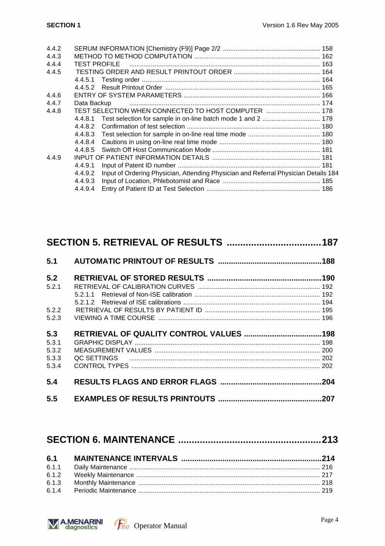
4.4.2 SERUM INFORMATION [Chemistry (F9)] Page 2/2 ...................................................... 1584.4.3 METHOD TO METHOD COMPUTATION ...................................................................... 1624.4.4 TEST PROFILE .......................................................................................................... 1634.4.5 TESTING ORDER AND RESULT PRINTOUT ORDER ................................................ 164
4.4.5.1 Testing order ................................................................................................... 1644.4.5.2 Result Printout Order ...................................................................................... 165
4.4.6 ENTRY OF SYSTEM PARAMETERS ............................................................................ 1664.4.7 Data Backup .......................................................................................................... 1744.4.8 TEST SELECTION WHEN CONNECTED TO HOST COMPUTER .............................. 178
4.4.8.1 Test selection for sample in on-line batch mode 1 and 2 ................................ 1784.4.8.2 Confirmation of test selection .......................................................................... 1804.4.8.3 Test selection for sample in on-line real time mode ........................................ 1804.4.8.4 Cautions in using on-line real time mode ........................................................ 1804.4.8.5 Switch Off Host Communication Mode ............................................................ 181
4.4.9 INPUT OF PATIENT INFORMATION DETAILS ............................................................ 1814.4.9.1 Input of Patent ID number ............................................................................... 1814.4.9.2 Input of Ordering Physician, Attending Physician and Referral Physician Details 1844.4.9.3 Input of Location, Phlebotomist and Race ...................................................... 1854.4.9.4 Entry of Patient ID at Test Selection ............................................................... 186
SECTION 5. RETRIEVAL OF RESULTS ...................................187
5.1 AUTOMATIC PRINTOUT OF RESULTS ................................................188
5.2 RETRIEVAL OF STORED RESULTS .....................................................1905.2.1 RETRIEVAL OF CALIBRATION CURVES .................................................................... 192
5.2.1.1 Retrieval of Non-ISE calibration ...................................................................... 1925.2.1.2 Retrieval of ISE calibrations ............................................................................ 194
5.2.2 RETRIEVAL OF RESULTS BY PATIENT ID ................................................................ 1955.2.3 VIEWING A TIME COURSE .......................................................................................... 196
5.3 RETRIEVAL OF QUALITY CONTROL VALUES ....................................1985.3.1 GRAPHIC DISPLAY ....................................................................................................... 1985.3.2 MEASUREMENT VALUES ............................................................................................ 2005.3.3 QC SETTINGS .......................................................................................................... 2025.3.4 CONTROL TYPES ......................................................................................................... 202
5.4 RESULTS FLAGS AND ERROR FLAGS ...............................................204
5.5 EXAMPLES OF RESULTS PRINTOUTS ................................................207
SECTION 6. MAINTENANCE .....................................................213
6.1 MAINTENANCE INTERVALS .................................................................2146.1.1 Daily Maintenance .......................................................................................................... 2166.1.2 Weekly Maintenance ...................................................................................................... 2176.1.3 Monthly Maintenance ..................................................................................................... 2186.1.4 Periodic Maintenance ..................................................................................................... 219
Page 4Operator Manual
SECTION 1 Version 1.6 Rev May 2005
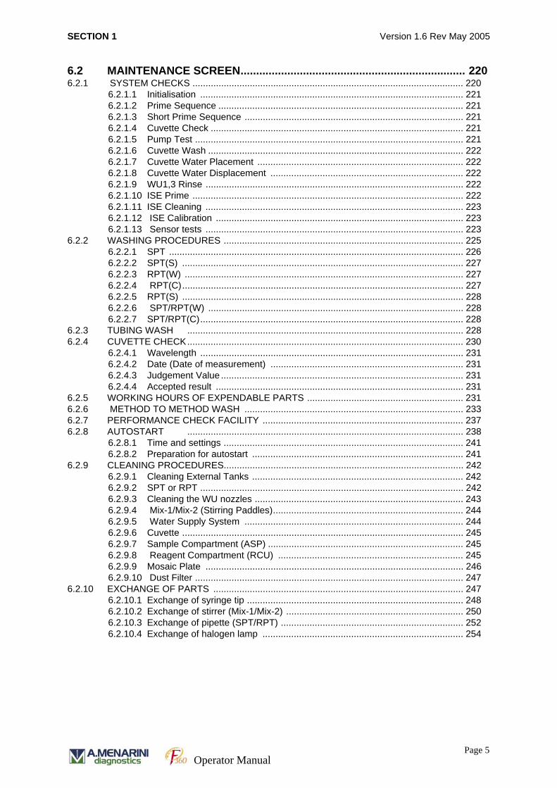
6.2 MAINTENANCE SCREEN........................................................................ 2206.2.1 SYSTEM CHECKS ........................................................................................................ 220
6.2.1.1 Initialisation ..................................................................................................... 2216.2.1.2 Prime Sequence .............................................................................................. 2216.2.1.3 Short Prime Sequence .................................................................................... 2216.2.1.4 Cuvette Check ................................................................................................. 2216.2.1.5 Pump Test ....................................................................................................... 2216.2.1.6 Cuvette Wash .................................................................................................. 2226.2.1.7 Cuvette Water Placement ............................................................................... 2226.2.1.8 Cuvette Water Displacement .......................................................................... 2226.2.1.9 WU1,3 Rinse ................................................................................................... 2226.2.1.10 ISE Prime ........................................................................................................ 2226.2.1.11 ISE Cleaning ................................................................................................... 2236.2.1.12 ISE Calibration ............................................................................................... 2236.2.1.13 Sensor tests ................................................................................................... 223
6.2.2 WASHING PROCEDURES ............................................................................................ 2256.2.2.1 SPT ................................................................................................................. 2266.2.2.2 SPT(S) ............................................................................................................ 2276.2.2.3 RPT(W) ........................................................................................................... 2276.2.2.4 RPT(C)............................................................................................................ 2276.2.2.5 RPT(S) ............................................................................................................ 2286.2.2.6 SPT/RPT(W) .................................................................................................. 2286.2.2.7 SPT/RPT(C)..................................................................................................... 228
6.2.3 TUBING WASH .......................................................................................................... 2286.2.4 CUVETTE CHECK.......................................................................................................... 230
6.2.4.1 Wavelength ..................................................................................................... 2316.2.4.2 Date (Date of measurement) .......................................................................... 2316.2.4.3 Judgement Value ............................................................................................. 2316.2.4.4 Accepted result ............................................................................................... 231
6.2.5 WORKING HOURS OF EXPENDABLE PARTS ............................................................ 2316.2.6 METHOD TO METHOD WASH .................................................................................... 2336.2.7 PERFORMANCE CHECK FACILITY ............................................................................. 2376.2.8 AUTOSTART .......................................................................................................... 238
6.2.8.1 Time and settings ............................................................................................ 2416.2.8.2 Preparation for autostart ................................................................................. 241
6.2.9 CLEANING PROCEDURES............................................................................................ 2426.2.9.1 Cleaning External Tanks ................................................................................. 2426.2.9.2 SPT or RPT ..................................................................................................... 2426.2.9.3 Cleaning the WU nozzles ................................................................................ 2436.2.9.4 Mix-1/Mix-2 (Stirring Paddles)......................................................................... 2446.2.9.5 Water Supply System .................................................................................... 2446.2.9.6 Cuvette ............................................................................................................ 2456.2.9.7 Sample Compartment (ASP) ........................................................................... 2456.2.9.8 Reagent Compartment (RCU) ....................................................................... 2456.2.9.9 Mosaic Plate ................................................................................................... 2466.2.9.10 Dust Filter ....................................................................................................... 247
6.2.10 EXCHANGE OF PARTS ................................................................................................ 2476.2.10.1 Exchange of syringe tip ................................................................................... 2486.2.10.2 Exchange of stirrer (Mix-1/Mix-2) .................................................................... 2506.2.10.3 Exchange of pipette (SPT/RPT) ...................................................................... 2526.2.10.4 Exchange of halogen lamp ............................................................................. 254
Page 5Operator Manual
SECTION 1 Version 1.6 Rev May 2005
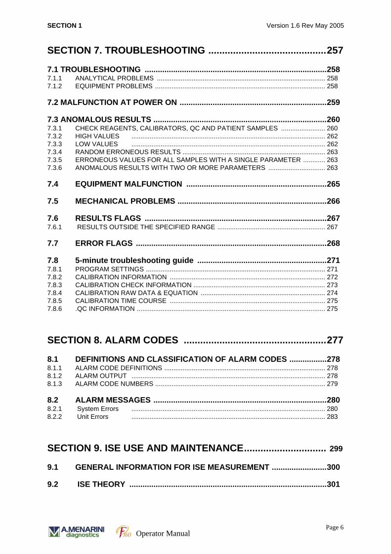
SECTION 7. TROUBLESHOOTING ...........................................257
7.1 TROUBLESHOOTING ...................................................................................2587.1.1 ANALYTICAL PROBLEMS ............................................................................................ 2587.1.2 EQUIPMENT PROBLEMS ............................................................................................. 258
7.2 MALFUNCTION AT POWER ON ...................................................................259
7.3 ANOMALOUS RESULTS ...............................................................................2607.3.1 CHECK REAGENTS, CALIBRATORS, QC AND PATIENT SAMPLES ........................ 2607.3.2 HIGH VALUES .......................................................................................................... 2627.3.3 LOW VALUES .......................................................................................................... 2627.3.4 RANDOM ERRONEOUS RESULTS .............................................................................. 2637.3.5 ERRONEOUS VALUES FOR ALL SAMPLES WITH A SINGLE PARAMETER ............ 2637.3.6 ANOMALOUS RESULTS WITH TWO OR MORE PARAMETERS ............................... 263
7.4 EQUIPMENT MALFUNCTION ................................................................265
7.5 MECHANICAL PROBLEMS ....................................................................266
7.6 RESULTS FLAGS ...................................................................................2677.6.1 RESULTS OUTSIDE THE SPECIFIED RANGE ........................................................... 267
7.7 ERROR FLAGS .......................................................................................268
7.8 5-minute troubleshooting guide ...........................................................2717.8.1 PROGRAM SETTINGS .................................................................................................. 2717.8.2 CALIBRATION INFORMATION ..................................................................................... 2727.8.3 CALIBRATION CHECK INFORMATION ........................................................................ 2737.8.4 CALIBRATION RAW DATA & EQUATION .................................................................... 2747.8.5 CALIBRATION TIME COURSE ..................................................................................... 2757.8.6 .QC INFORMATION ....................................................................................................... 275
SECTION 8. ALARM CODES ....................................................277
8.1 DEFINITIONS AND CLASSIFICATION OF ALARM CODES .................2788.1.1 ALARM CODE DEFINITIONS ........................................................................................ 2788.1.2 ALARM OUTPUT .......................................................................................................... 2788.1.3 ALARM CODE NUMBERS ............................................................................................. 279
8.2 ALARM MESSAGES ...............................................................................2808.2.1 System Errors .......................................................................................................... 2808.2.2 Unit Errors .......................................................................................................... 283
SECTION 9. ISE USE AND MAINTENANCE.............................. 299
9.1 GENERAL INFORMATION FOR ISE MEASUREMENT .........................300
9.2 ISE THEORY ..........................................................................................301
Page 6Operator Manual
SECTION 1 Version 1.6 Rev May 2005
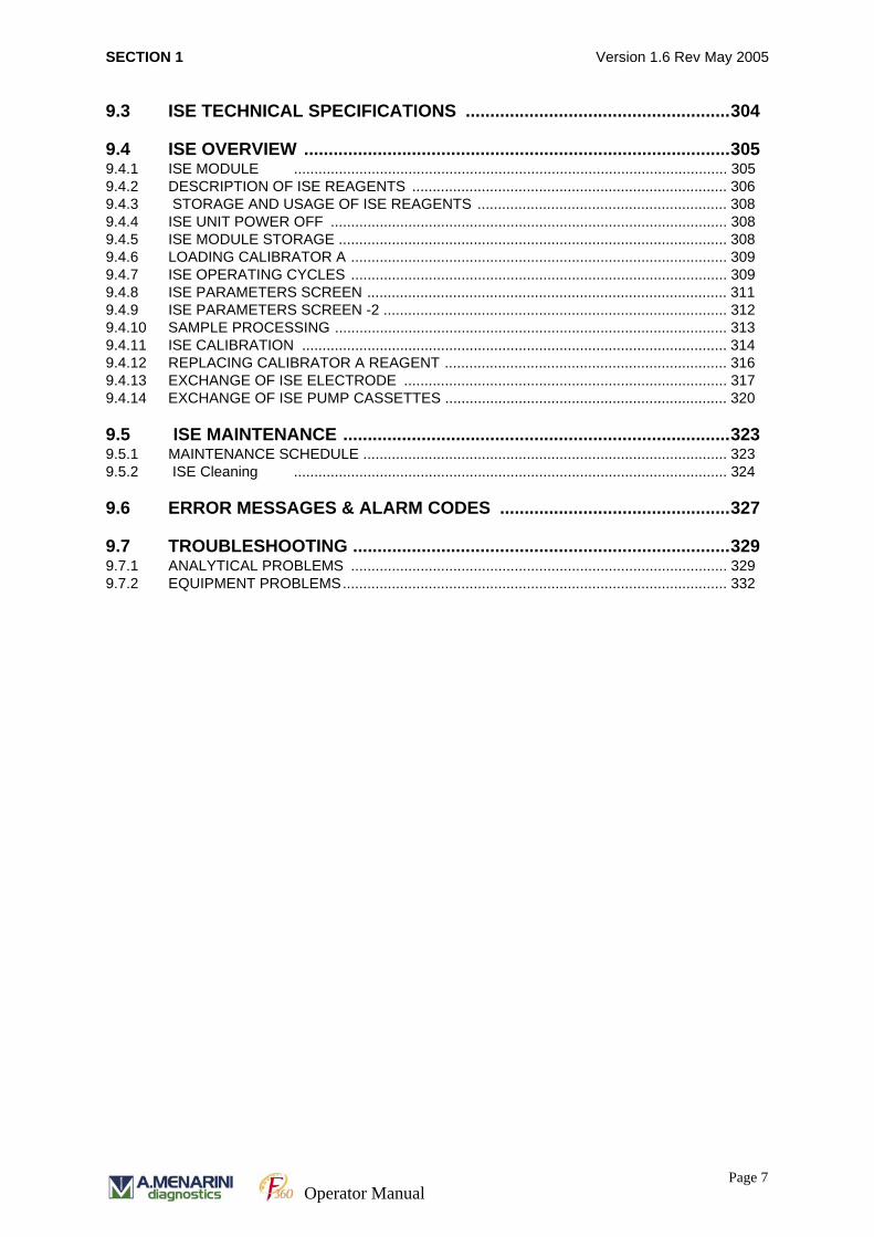
9.3 ISE TECHNICAL SPECIFICATIONS ......................................................304
9.4 ISE OVERVIEW .......................................................................................3059.4.1 ISE MODULE .......................................................................................................... 3059.4.2 DESCRIPTION OF ISE REAGENTS ............................................................................. 3069.4.3 STORAGE AND USAGE OF ISE REAGENTS ............................................................. 3089.4.4 ISE UNIT POWER OFF ................................................................................................. 3089.4.5 ISE MODULE STORAGE ............................................................................................... 3089.4.6 LOADING CALIBRATOR A ............................................................................................ 3099.4.7 ISE OPERATING CYCLES ............................................................................................ 3099.4.8 ISE PARAMETERS SCREEN ........................................................................................ 3119.4.9 ISE PARAMETERS SCREEN -2 .................................................................................... 3129.4.10 SAMPLE PROCESSING ................................................................................................ 3139.4.11 ISE CALIBRATION ........................................................................................................ 3149.4.12 REPLACING CALIBRATOR A REAGENT ..................................................................... 3169.4.13 EXCHANGE OF ISE ELECTRODE ............................................................................... 3179.4.14 EXCHANGE OF ISE PUMP CASSETTES ..................................................................... 320
9.5 ISE MAINTENANCE ...............................................................................3239.5.1 MAINTENANCE SCHEDULE ......................................................................................... 3239.5.2 ISE Cleaning .......................................................................................................... 324
9.6 ERROR MESSAGES & ALARM CODES ...............................................327
9.7 TROUBLESHOOTING .............................................................................3299.7.1 ANALYTICAL PROBLEMS ............................................................................................ 3299.7.2 EQUIPMENT PROBLEMS.............................................................................................. 332
Page 7Operator Manual
SECTION 1 Version 1.6 Rev May 2005
APPENDIX A. THEORY OF CALCULATIONS ..............................................333
A. 1 Data processing and conversion .................................................................... 333 A. 1.1 Reaction process and measuring point ...................... 333
A. 1.1.1Water blank ................................................. 333 A. 1.2 Absorbance data ........................................................ 333
A. 2r Examples for assay types with end method .................................................. 334 A. 2.1 End 1 (1 point End-method) ...................................... 334 A. 2.2 END2(2 Point End-method) ..................................... 335
A. 3 Examples for Assay Types with Rate-method ............................................... 337 A. 3.1 RATE1(1 point Rate-method) ................................... 337 A. 3.2 RATE2 (2 point Rate-method) .................................. 338
A. 3.2.1Reagent Blank Correction ........................... 339 A. 4 Measurement result check ............................................................................ 339
A. 4.1 Linearity Check ......................................................... 340 A. 4.2 Absorbance Limit Check ........................................... 341
A. 4.2.1Setting of Absorbance Limit check ............. 341 A. 4.2.1.1 For a decreasing reaction: .......... 341 A. 4.2.1.2For the example of a increasing reaction: ...................................................................... 342
A. 4.2.1.3Absorbance of Limit Check Flags 343 A. 4.3 Prozone Check for rate assays ................................... 343
A. 4.3.1Prozone check for end method .................... 345 A. 4.3.1.1Prozone setting at End method .... 345 A. 4.3.1.2Prozone Limit Check Box *1 ...... 346 A. 4.3.1.3Prozone Limit Check Box *2....... 347 A. 4.3.1.4Upper/Lower setting *3 ............... 347 A. 4.3.1.5Prozone Limit range setting (*4).. 347 A. 4.3.1.6Sens value setting (*5) ................ 348
A. 4.3.2FORMULA .................................................. 348 A. 4.3.2.1Actual measurement value .......... 348
A. 4.3.3Prozone check formula ................................ 349 A. 4.3.4Sens check formula ...................................... 349
A. 5 Calibration ..................................................................................................... 349 A. 5.1 Measurement Principles of Calibration ..................... 349 A. 5.2 Calibration Check ...................................................... 350
A. 5.2.1Duplicate Limit (Allowable variation limit) 350 A. 5.2.2Sensitivity (Allowable sensitivity limit) ...... 350
A. 5.3 Calibration Type ........................................................ 351 A. 5.3.1Factor ........................................................... 351 A. 5.3.2Linear ........................................................... 352 A. 5.3.3 Spline .......................................................... 353 A. 5.3.4Point to point ............................................... 354
APPENDIX B. MAINTENANCE LOG SHEETS ...................................................357
APPENDIX C. SOFTWARE UPGRADE PROCEDURE .....................................359 C. 1 Backup of System Parameters ...................................................................... 359 C. 2 Terminate all programs on the PC. ................................................................ 359 C. 3 User-interface Software Upgrade (on Windows XP) ..................................... 360
C. 3.1 Removal of Old User-interface Program .................... 360
Page 8Operator Manual
SECTION 1 Version 1.6 Rev May 2005
C. 3.2 Installation of New User-interface Program .............. 360 C. 3.3 Restoration of System Parameters ............................... 361 C. 3.4 Final Check .................................................................... 361
APPENDIX D. F360 CUSTOMER PACKING LIST .............................................365 D. 1 F360 with ISE PACKING LIST ...................................................................... 365 D. 2 F360 without ISE ........................................................................................... 370
APPENDIX E. SPARE PARTS LIST.................................................................... 373
APPENDIX F. GLOSSARY .................................................................................375
APPENDIX G. Chemistry Parameter Importing Software ...............................377
G. 1 Overview ...................................................................................................... 377 G. 1.1Software versions ............................................................. 377 G. 1.2Maximum Capacity .......................................................... 377 G. 1.3Limitation ......................................................................... 377 G. 1.4Installation ........................................................................ 378 G. 1.5Download Software (PC to analyser) ............................... 378 G. 1.6Installation ........................................................................ 378 G. 1.7User Interface ................................................................... 379 G. 1.8Operation Procedure ......................................................... 379 G. 1.9Update parameters file to latest version ........................... 380 G. 1.10 Load new methods into analyser ................................... 381 G. 1.11Update existing methods stored in analyser ................... 381
Page 9Operator Manual

SECTION 1 Version 1.6 Rev May 2005
Page 10Operator Manual

SECTION 1 Version 1.6 Rev May 2005
FOREWORD is an automated clinical chemistry analyser complete with dedicated
analyser software. Software functions of the analyser include the facility to interact
with a host computer for direct download of test method selection details for individual
samples.
A barcode system is used for the rapid identification of patient samples, reagents and
QC samples.
This analyser is an “in vitro diagnostic (IVD) medical device” and conforms to the IVD
directive (98/79/EC) and the EMC directive (89/336/EEC) of EU. This analyser has
been evaluated to canadian safety requirements.
This manual is written for personnel that have completed the F360 training course, or
those that have been fully trained by individuals that have attended the training
course.
The aim of the manual is to familiarise the user with all the features and functions of
the analyser to ensure analysis is performed under safe and optimal conditions.
This manual was produced for PC128 version of the F360 software.
C lin ic a l
C h e m is try
A n a ly s e r
3 X A 6
C lin ic a l
C h e m is try
A n a ly s e r
3 X A 6
©2006 by A. MENARINI Diagnostics S.r.l.
All rights reserved. No part of this publication may be reproduced, stored in a retrieval system, or transmitted in any form or by any means, electronic, mechanical, photocopying, microfilming, recording or otherwise without the written permission of the publisher.
Via Sette Santi, 3 - 50131 Firenze (Italy)
Page 11 Operator Manual

SECTION 1 SAFETY PRECAUTIONS AND INSTALLATION Version 1.6 Rev May 2005
SECTION 1
SAFETY PRECAUTIONS AND INSTALLATION
Page 12
Operator Manual
SECTION 1 SAFETY PRECAUTIONS AND INSTALLATION Version 1.6 Rev May 2005
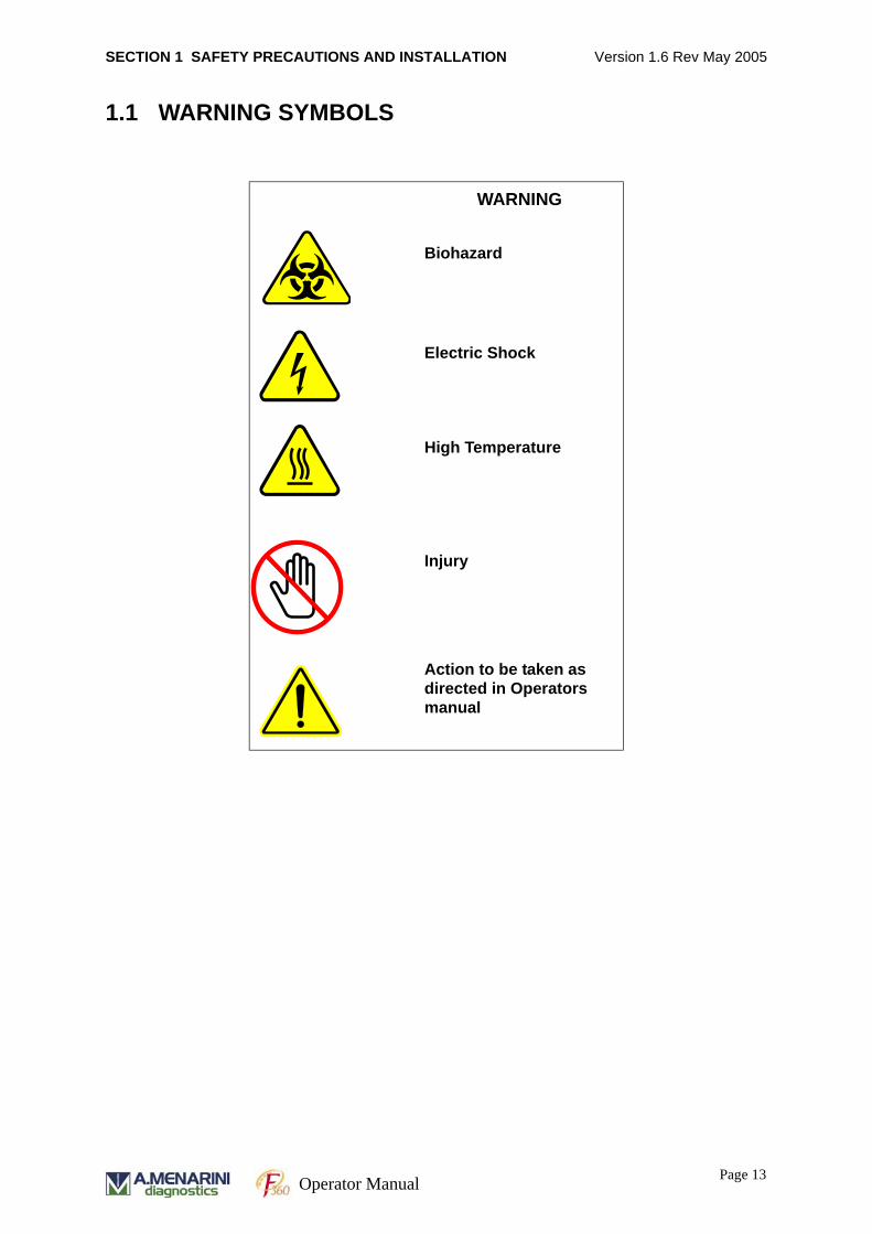
1.1 WARNING SYMBOLS
WARNING
Biohazard
Electric Shock
High Temperature
Injury
Action to be taken as directed in Operators manual
Page 13 Operator Manual
SECTION 1 SAFETY PRECAUTIONS AND INSTALLATION Version 1.6 Rev May 2005
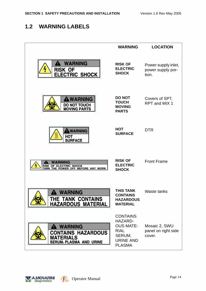
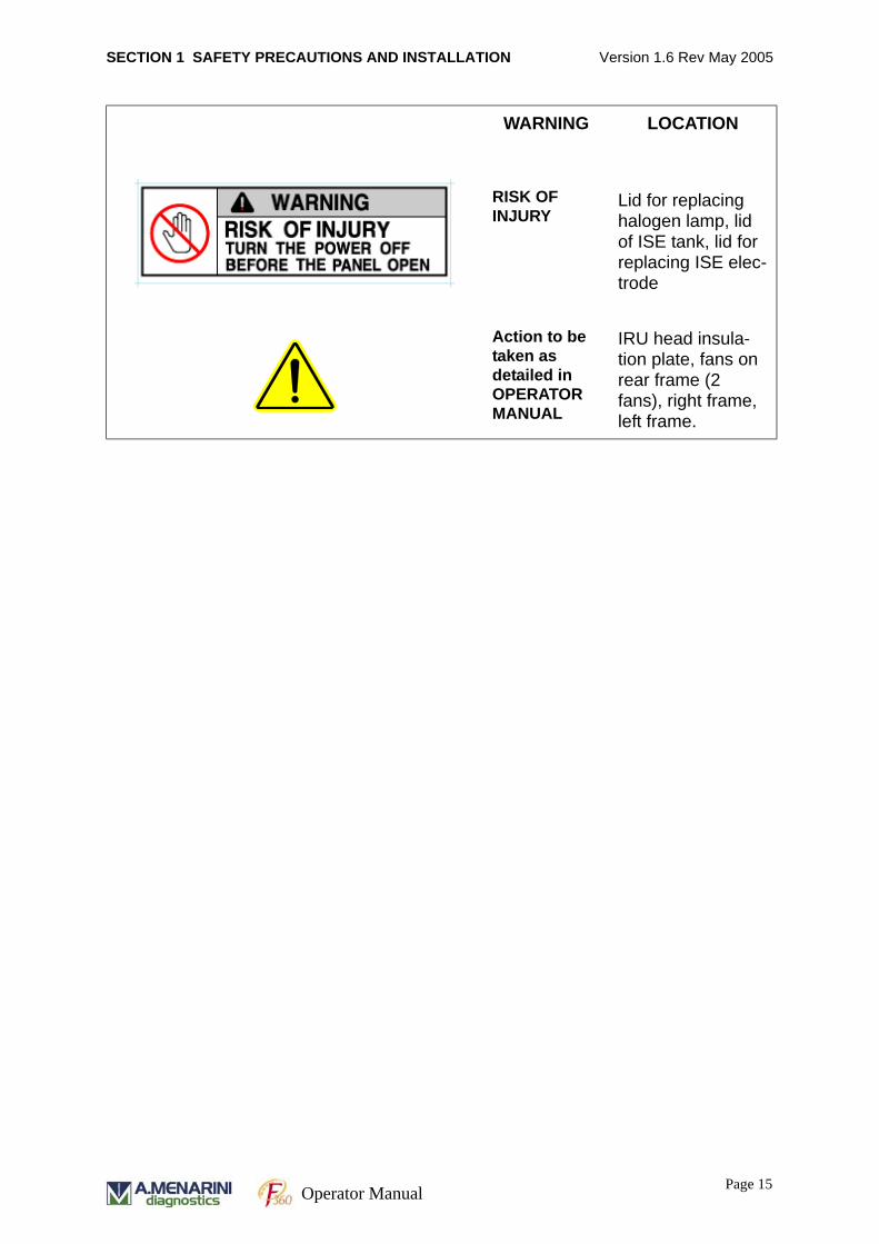
1.2 WARNING LABELS
WARNING LOCATION
RISK OF ELECTRIC SHOCK
Power supply inlet, power supply por-tion.
DO NOT TOUCH MOVING PARTS
Covers of SPT, RPT and MIX 1
HOT SURFACE
DTR
RISK OF ELECTRIC SHOCK
Front Frame
THIS TANK CONTAINS HAZARDOUS MATERIAL
Waste tanks
CONTAINS HAZARD-OUS MATE-RIAL SERUM, URINE AND PLASMA
Mosaic 2, SWU panel on right side cover.
Page 14
Operator Manual
SECTION 1 SAFETY PRECAUTIONS AND INSTALLATION Version 1.6 Rev May 2005
RISK OF INJURY
Lid for replacing halogen lamp, lid of ISE tank, lid for replacing ISE elec-trode
Action to be taken as detailed in OPERATOR MANUAL
IRU head insula-tion plate, fans on rear frame (2 fans), right frame, left frame.
WARNING LOCATION
Page 15 Operator Manual
SECTION 1 SAFETY PRECAUTIONS AND INSTALLATION Version 1.6 Rev May 2005
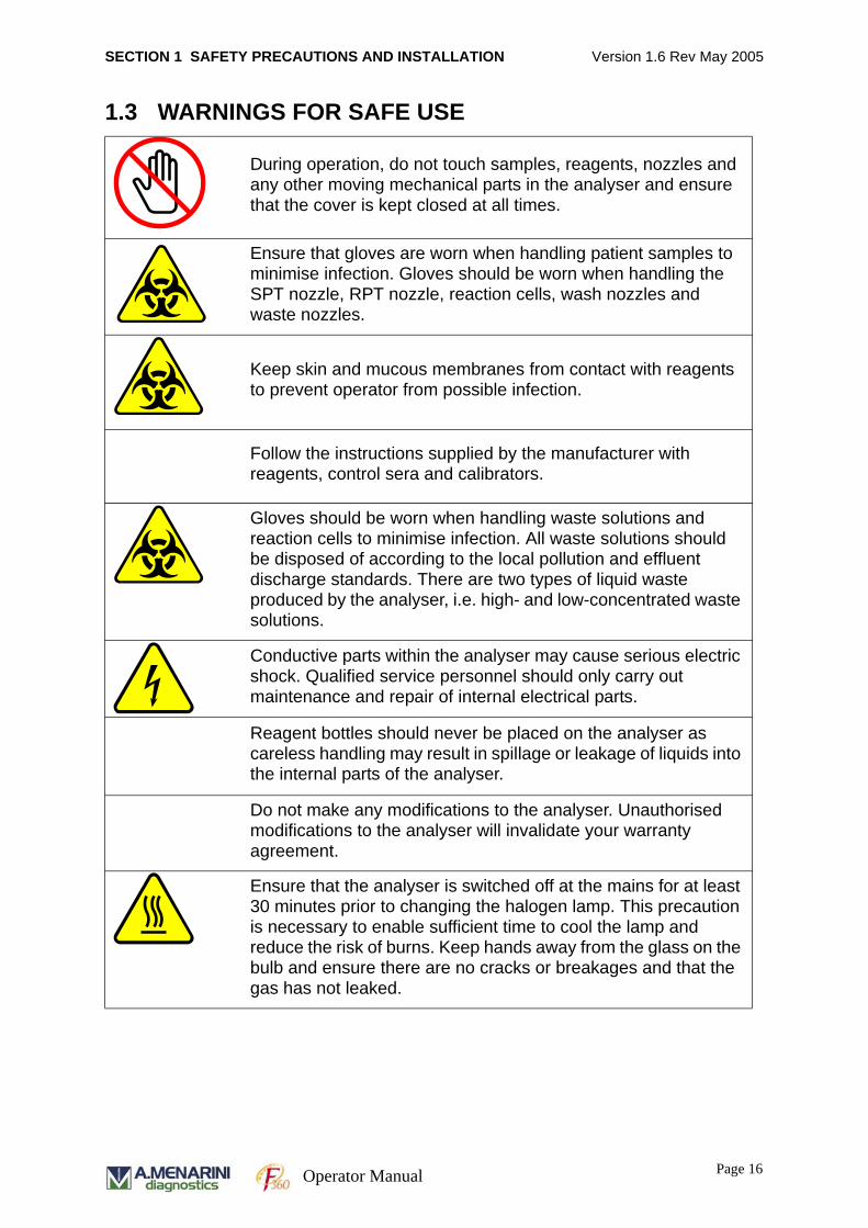
1.3 WARNINGS FOR SAFE USE
During operation, do not touch samples, reagents, nozzles and any other moving mechanical parts in the analyser and ensure that the cover is kept closed at all times.
Ensure that gloves are worn when handling patient samples to minimise infection. Gloves should be worn when handling the SPT nozzle, RPT nozzle, reaction cells, wash nozzles and waste nozzles.
Keep skin and mucous membranes from contact with reagents to prevent operator from possible infection.
Follow the instructions supplied by the manufacturer with reagents, control sera and calibrators.
Gloves should be worn when handling waste solutions and reaction cells to minimise infection. All waste solutions should be disposed of according to the local pollution and effluent discharge standards. There are two types of liquid waste produced by the analyser, i.e. high- and low-concentrated waste solutions.
Conductive parts within the analyser may cause serious electric shock. Qualified service personnel should only carry out maintenance and repair of internal electrical parts.
Reagent bottles should never be placed on the analyser as careless handling may result in spillage or leakage of liquids into the internal parts of the analyser.
Do not make any modifications to the analyser. Unauthorised modifications to the analyser will invalidate your warranty agreement.
Ensure that the analyser is switched off at the mains for at least 30 minutes prior to changing the halogen lamp. This precaution is necessary to enable sufficient time to cool the lamp and reduce the risk of burns. Keep hands away from the glass on the bulb and ensure there are no cracks or breakages and that the gas has not leaked.
Page 16
Operator Manual
SECTION 1 SAFETY PRECAUTIONS AND INSTALLATION Version 1.6 Rev May 2005
1.4 SAFETY PRECAUTIONSPLEASE READ THIS INSTRUCTION MANUAL BEFORE USING THE ANALYSER
AND BECOME ACQUAINTED WITH THE RECOMMENDED SAFETY ISSUES AND
PROCEDURES.
Prevention of system damage
• Ensure installation of the system is carried out according to the recommendations
provided with the F360 Installation Guide.
• Do not make any modifications to the analyser.
Prevention of electric shocks
• Do not remove any covers secured by screws only, as there is a risk of electric
shock. Covers secured with plastic clips may be removed as demonstrated in the
F360 Operator Training Course. Contact your service department if the system
requires attention.
• In the event of a liquid spill inside the system, contact the service department.
Prevention of personal injury
• Do not touch moving mechanical parts such as the reagent or sampling probes,
while the system is in operation. During operation, ensure that the cover is closed.
• Observe the warning labels described in this manual.
• Ensure the system has been switched off at the mains for at least 30 minutes
before changing the halogen lamp. This precaution is necessary to enable
sufficient time to cool the lamp and reduce the risk of burns. System calibration
should be performed when a lamp is changed. Keep hands away from the glass
on the bulb and ensure there are no cracks or breakage or that the gas has
leaked.
System accuracy and precision
• Ensure the cover is closed while the system is in operation.
• Perform the system preparation checks described in this manual before starting
routine operation.
Page 17 Operator Manual
SECTION 1 SAFETY PRECAUTIONS AND INSTALLATION Version 1.6 Rev May 2005
• Follow the instructions supplied by the manufacturer with reagents, control sera
and calibrators.
• Do not place reagent bottles or sample cups on the analyser to prevent spillages
and system malfunction.
Waste Liquids
• All waste solutions should be disposed of according to the local pollution and
effluent discharge standards. There are two types of waste generated by this
analyser, low-concentration and high-concentration waste.
Prevention of Infection
• Gloves should be worn at all times when handling patient samples and waste
liquid, to protect from possible infection.
• Gloves should always be worn when handling the SPT nozzle, RPT nozzle,
reaction cells, wash nozzles and waste nozzles.
Reagent Handling
• Ensure that your hands and clothing do not come into contact with reagents as
they may contain strong acid or alkali.
General Precautions
• The system is designed to run serum, plasma, supernatants, urine, and CSF.
Please contact Technical Support department if you want to run any other sample
types.
• Ensure that samples are free from clots and debris to prevent blockage of the
reagent and sampling probes.
• Ensure that the correct reagent volume is available to perform the necessary
number of tests.
• Do not leave samples unsealed for extended periods as they may evaporate and
concentrate the sample.
• Follow the instructions in this manual for loading samples, reagents and
calibration samples.
• Ensure that calibration analysis is complete before routine operation.
Page 18
Operator Manual
SECTION 1 SAFETY PRECAUTIONS AND INSTALLATION Version 1.6 Rev May 2005
• Ensure that periodic system checks are performed and parts are replaced as
required.
• If reagents or samples come into contact with the mucous membranes, flush with
copious amounts of water for at least 15 minutes. Ensure adequate flushing of
eyes by separating eyelids with fingers. If swallowed, wash out mouth with water
providing that the person is conscious. Then contact a doctor as soon as possible.
In case of skin contact immediately wash skin with soap and copious quantities of
water.
• Never use the system for a purpose other than its intended use.
Emergency Shutdown Procedure
During routine analysis, an emergency stop is possible by pressing [Control] and [F2]
keys simultaneously. The software will also interrupt routine operation when there is a
fault in the analyser.
ANALYSIS DATA WILL BE LOST when an emergency stop is initiated. The following
procedures should be followed before resuming operation:
1. The cause of the emergency interruption must be resolved. For example, in case
of the user interruption due to the settings of erroneous measuring conditions, the
correct settings are required.
2. In the case of an automatic system emergency interruption, open the cover of the
equipment and check that there are no items interfering with the mechanical
operation of the equipment. When the cause of emergency interruption is
unknown, contact Technical Support to resolve the problem.
Page 19 Operator Manual

SECTION 1 SAFETY PRECAUTIONS AND INSTALLATION Version 1.6 Rev May 2005
1.5 INSTALLATION REQUIREMENTSPLEASE READ THIS INSTRUCTION MANUAL BEFORE USING THE ANALYSER
AND BECOME ACQUAINTED WITH THE RECOMMENDED SAFETY ISSUES AND
PROCEDURES.
The recommended installation instructions detailed in the F360 Installation Guide
should be followed to ensure that system operation is unaffected by external facilities
and conditions.
Recommended installation environment
• Avoid exposure to direct sunlight.
• Minimum exposure to dust and other airborne particles.
• Site should be flat.
• Minimum vibration.
• Site should be of suitable construction to accommodate the weight of the analyser.
• Adequate uninterrupted power source.
• Ensure adequate air circulation around the back of the analyser.
• Site should be well ventilated.
• Ensure adequate atmospheric pressure.
• Do not install the analyser adjacent to a chemical storage room or any other
facility where gases are likely to be generated.
• Do not install the analyser adjacent to a localized heat source such as a
refrigerator or freezer.
Installation Precautions
• Only qualified personnel should install and use the analyser.
• Protect the analyser from liquid spillage or splashes.
• The analyser weighs 135kgs and should be lifted by at least four personnel. Lift
the analyser using the grips on the bottom four corners of the analyser.
• Ensure the analyser is appropriately grounded.
• Analyser use in the USA requires UL-certified accessories.
• Connect the analyser to the PC using LAN cable provided. Other cables may
cause background noise or interference.
Page 20
Operator Manual
SECTION 1 SAFETY PRECAUTIONS AND INSTALLATION Version 1.6 Rev May 2005
• Ensure that all electrical cables are correctly connected.
• Water quality of feed water into analyser should conform to NCCLS Type II
specification or better.
Operation Precautions
• Observe the recommended installation environment and precautions as described
above.
• Ensure that the ambient temperature of the laboratory is between 15-30°C to
ensure effective cooling of the reagents.
• Ensure that electric cables are correctly connected.
• Follow daily maintenance procedure before operating analyser. Ensure that
gloves are worn when handling sample nozzles, reagents and samples.
• Ensure sufficient reagent volumes for routine operation.
• Follow the recommended maintenance schedule to ensure efficient operation of
the system.
• Shutdown the system completely when a serious malfunction is detected in the
analyser.
IMPORTANT
Warranty agreements will be invalidated if any of the following specifications are
ignored.
• The environmental conditions do not adhere to the specifications listed in this
manual.
• The analyser is operated by untrained personnel.
• The analyser is serviced or modified by unspecified engineers.
• If any replacement parts are not sourced from an authorised supplier.
Page 21 Operator Manual
SECTION 1 SAFETY PRECAUTIONS AND INSTALLATION Version 1.6 Rev May 2005
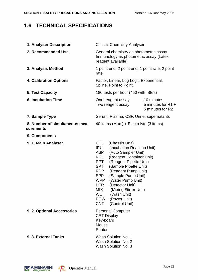
1.6 TECHNICAL SPECIFICATIONS
1. Analyser Description Clinical Chemistry Analyser
2. Recommended Use General chemistry as photometric assayImmunology as photometric assay (Latex reagent available)
3. Analysis Method 1 point end, 2 point end, 1 point rate, 2 point rate
4. Calibration Options Factor, Linear, Log Logit, Exponential, Spline, Point to Point.
5. Test Capacity 180 tests per hour (450 with ISE’s)
6. Incubation Time One reagent assay 10 minutesTwo reagent assay 5 minutes for R1 +
5 minutes for R2
7. Sample Type Serum, Plasma, CSF, Urine, supernatants
8. Number of simultaneous mea-surements
40 items (Max.) + Electrolyte (3 items)
9. Components
9. 1. Main Analyser CHS (Chassis Unit)IRU (Incubation Reaction Unit)ASP (Auto Sampler Unit)RCU (Reagent Container Unit)RPT (Reagent Pipette Unit)SPT (Sample Pipette Unit)RPP (Reagent Pump Unit)SPP (Sample Pump Unit)WPP (Water Pump Unit)DTR (Detector Unit)MIX (Mixing Stirrer Unit)WU (Wash Unit)POW (Power Unit)CNT (Control Unit)
9. 2. Optional Accessories Personal ComputerCRT DisplayKey-boardMousePrinter
9. 3. External Tanks Wash Solution No. 1Wash Solution No. 2Wash Solution No. 3
Page 22
Operator Manual
SECTION 1 SAFETY PRECAUTIONS AND INSTALLATION Version 1.6 Rev May 2005
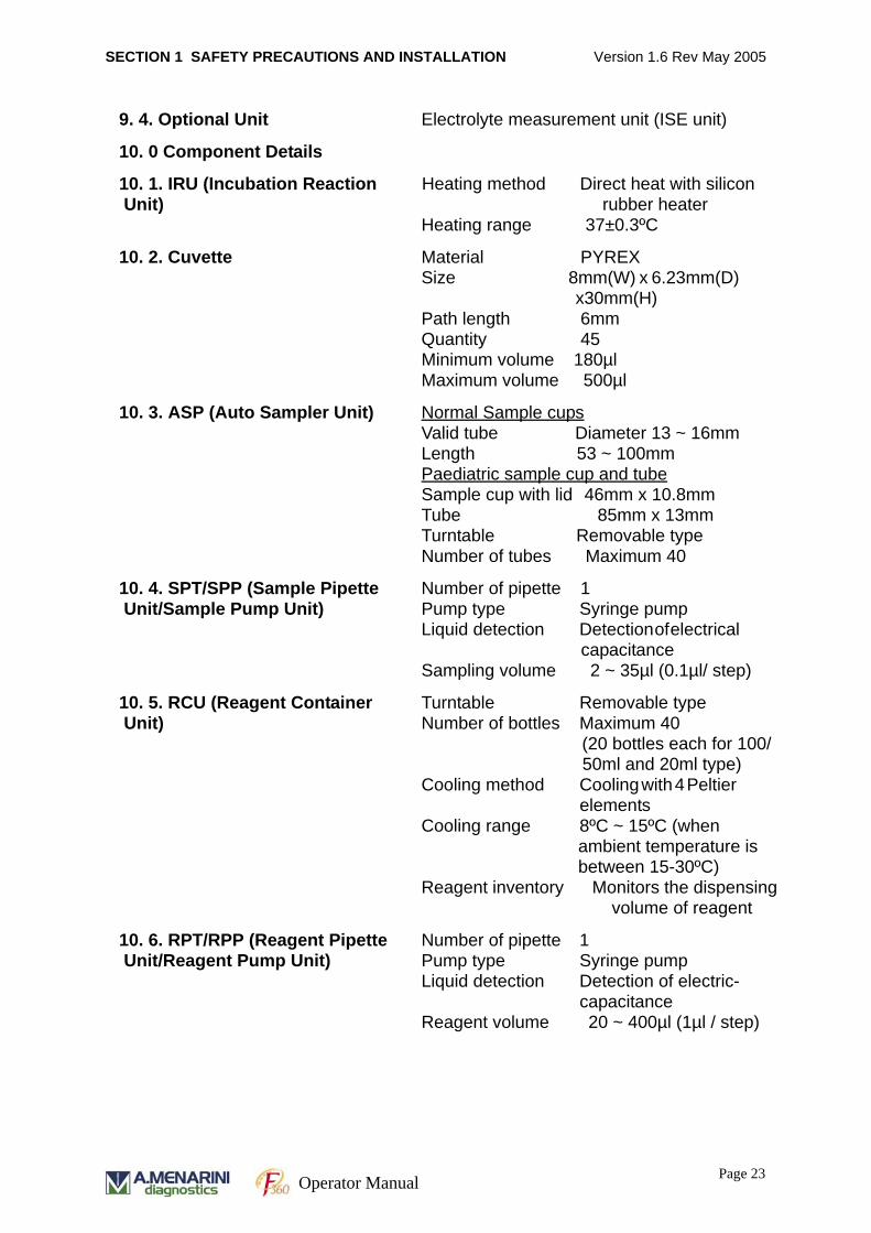
9. 4. Optional Unit Electrolyte measurement unit (ISE unit)
10. 0 Component Details
10. 1. IRU (Incubation Reaction Unit)
Heating method Direct heat with silicon rubber heaterHeating range 37±0.3ºC
10. 2. Cuvette Material PYREXSize 8mm(W) x 6.23mm(D)
x30mm(H)Path length 6mmQuantity 45Minimum volume 180µlMaximum volume 500µl
10. 3. ASP (Auto Sampler Unit) Normal Sample cupsValid tube Diameter 13 ~ 16mmLength 53 ~ 100mmPaediatric sample cup and tubeSample cup with lid 46mm x 10.8mmTube 85mm x 13mmTurntable Removable typeNumber of tubes Maximum 40
10. 4. SPT/SPP (Sample Pipette Unit/Sample Pump Unit)
Number of pipette 1Pump type Syringe pumpLiquid detection Detection of electrical
capacitanceSampling volume 2 ~ 35µl (0.1µl/ step)
10. 5. RCU (Reagent Container Unit)
Turntable Removable typeNumber of bottles Maximum 40
(20 bottles each for 100/50ml and 20ml type)
Cooling method Cooling with 4 Peltier elements
Cooling range 8ºC ~ 15ºC (when ambient temperature is between 15-30ºC)
Reagent inventory Monitors the dispensing volume of reagent
10. 6. RPT/RPP (Reagent Pipette Unit/Reagent Pump Unit)
Number of pipette 1Pump type Syringe pumpLiquid detection Detection of electric-
capacitanceReagent volume 20 ~ 400µl (1µl / step)
Page 23 Operator Manual
SECTION 1 SAFETY PRECAUTIONS AND INSTALLATION Version 1.6 Rev May 2005
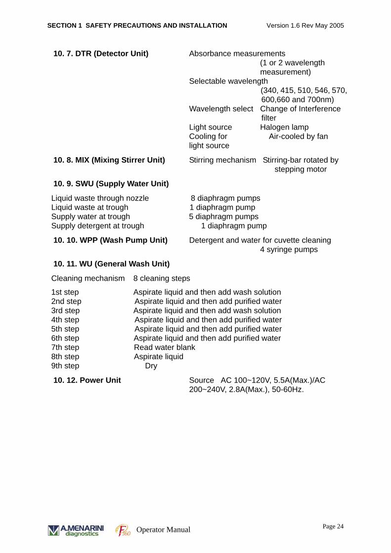
10. 7. DTR (Detector Unit) Absorbance measurements (1 or 2 wavelength measurement)
Selectable wavelength (340, 415, 510, 546, 570, 600,660 and 700nm)
Wavelength select Change of Interference filter
Light source Halogen lampCooling for Air-cooled by fanlight source
10. 8. MIX (Mixing Stirrer Unit) Stirring mechanism Stirring-bar rotated by stepping motor
10. 9. SWU (Supply Water Unit)
Liquid waste through nozzle 8 diaphragm pumpsLiquid waste at trough 1 diaphragm pumpSupply water at trough 5 diaphragm pumpsSupply detergent at trough 1 diaphragm pump
10. 10. WPP (Wash Pump Unit) Detergent and water for cuvette cleaning4 syringe pumps
10. 11. WU (General Wash Unit)
Cleaning mechanism 8 cleaning steps
1st step Aspirate liquid and then add wash solution 2nd step Aspirate liquid and then add purified water3rd step Aspirate liquid and then add wash solution4th step Aspirate liquid and then add purified water5th step Aspirate liquid and then add purified water6th step Aspirate liquid and then add purified water7th step Read water blank8th step Aspirate liquid 9th step Dry
10. 12. Power Unit Source AC 100~120V, 5.5A(Max.)/AC 200~240V, 2.8A(Max.), 50-60Hz.
Page 24
Operator Manual
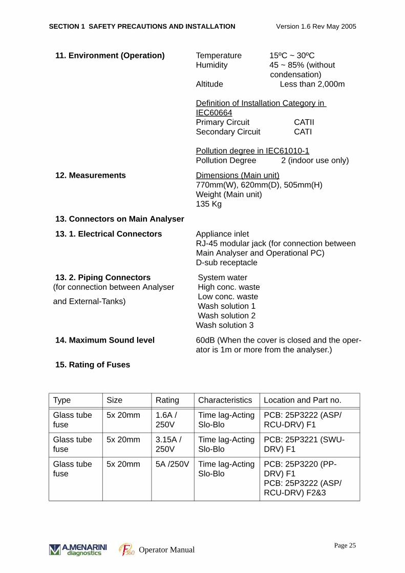
SECTION 1 SAFETY PRECAUTIONS AND INSTALLATION Version 1.6 Rev May 2005
11. Environment (Operation) Temperature 15ºC ~ 30ºCHumidity 45 ~ 85% (without
condensation)Altitude Less than 2,000m
Definition of Installation Category in IEC60664Primary Circuit CATIISecondary Circuit CATI
Pollution degree in IEC61010-1Pollution Degree 2 (indoor use only)
12. Measurements Dimensions (Main unit)770mm(W), 620mm(D), 505mm(H) Weight (Main unit)135 Kg
13. Connectors on Main Analyser
13. 1. Electrical Connectors Appliance inletRJ-45 modular jack (for connection between Main Analyser and Operational PC)D-sub receptacle
13. 2. Piping Connectors (for connection between Analyser
and External-Tanks)
System waterHigh conc. waste Low conc. wasteWash solution 1Wash solution 2Wash solution 3
14. Maximum Sound level 60dB (When the cover is closed and the oper-ator is 1m or more from the analyser.)
15. Rating of Fuses
Type Size Rating Characteristics Location and Part no.
Glass tube fuse
5x 20mm 1.6A /250V
Time lag-ActingSlo-Blo
PCB: 25P3222 (ASP/RCU-DRV) F1
Glass tube fuse
5x 20mm 3.15A /250V
Time lag-ActingSlo-Blo
PCB: 25P3221 (SWU-DRV) F1
Glass tube fuse
5x 20mm 5A /250V Time lag-ActingSlo-Blo
PCB: 25P3220 (PP-DRV) F1PCB: 25P3222 (ASP/RCU-DRV) F2&3
Page 25 Operator Manual
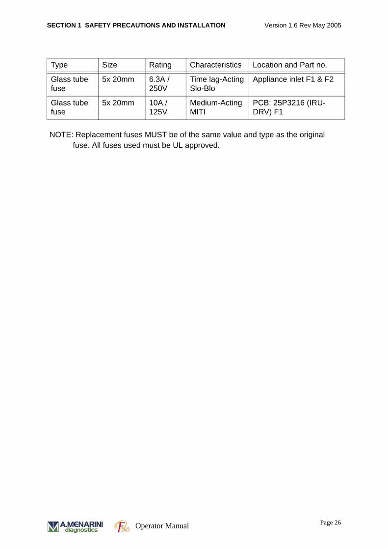
SECTION 1 SAFETY PRECAUTIONS AND INSTALLATION Version 1.6 Rev May 2005
Glass tube fuse
5x 20mm 6.3A /250V
Time lag-ActingSlo-Blo
Appliance inlet F1 & F2
Glass tube fuse
5x 20mm 10A /125V
Medium-ActingMITI
PCB: 25P3216 (IRU-DRV) F1
Type Size Rating Characteristics Location and Part no.
NOTE: Replacement fuses MUST be of the same value and type as the original fuse. All fuses used must be UL approved.
Page 26
Operator Manual
SECTION 1 SAFETY PRECAUTIONS AND INSTALLATION Version 1.6 Rev May 2005
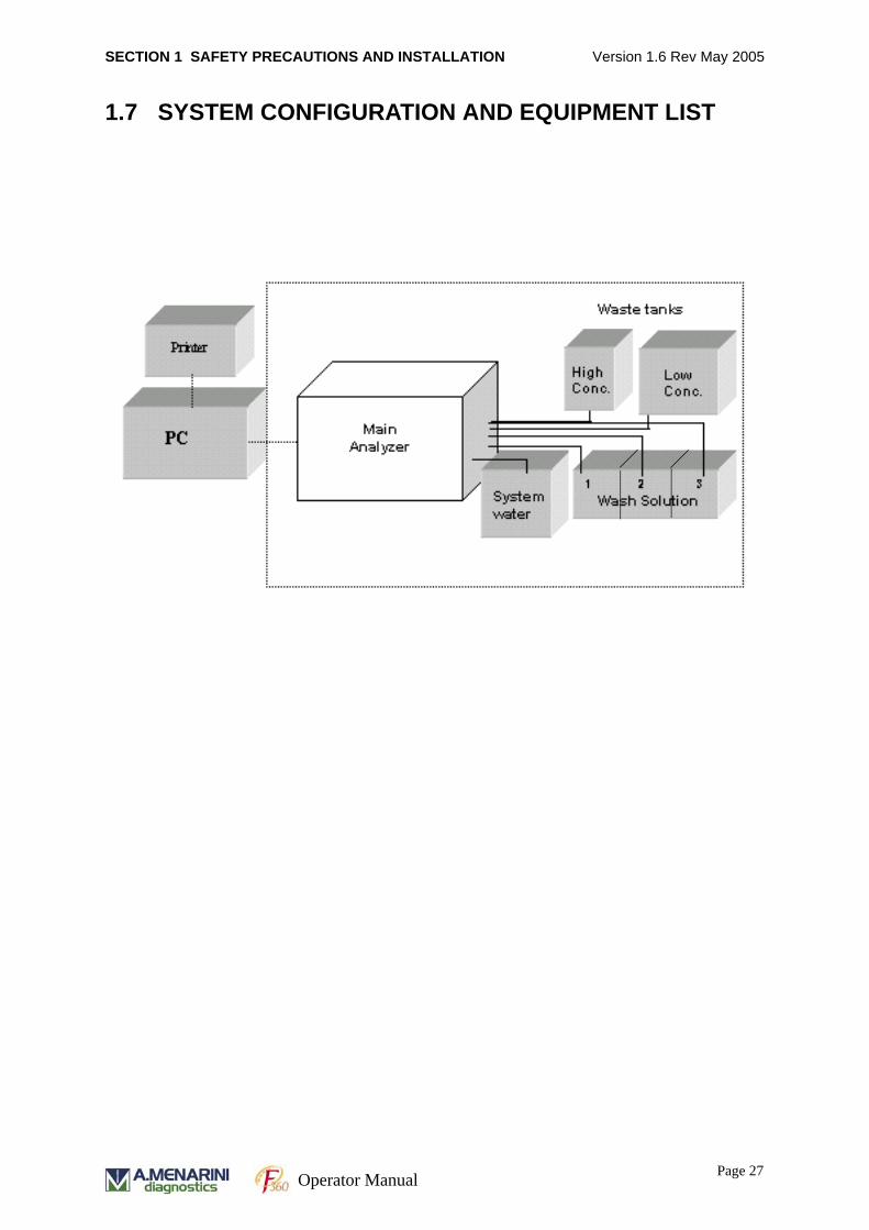
1.7 SYSTEM CONFIGURATION AND EQUIPMENT LIST
Page 27 Operator Manual
SECTION 1 SAFETY PRECAUTIONS AND INSTALLATION Version 1.6 Rev May 2005
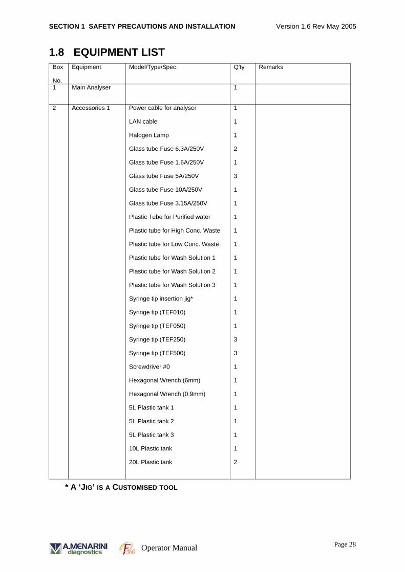
1.8 EQUIPMENT LISTBox
No.
Equipment Model/Type/Spec. Q'ty Remarks
1 Main Analyser 1
2 Accessories 1 Power cable for analyser
LAN cable
Halogen Lamp
Glass tube Fuse 6.3A/250V
Glass tube Fuse 1.6A/250V
Glass tube Fuse 5A/250V
Glass tube Fuse 10A/250V
Glass tube Fuse 3.15A/250V
Plastic Tube for Purified water
Plastic tube for High Conc. Waste
Plastic tube for Low Conc. Waste
Plastic tube for Wash Solution 1
Plastic tube for Wash Solution 2
Plastic tube for Wash Solution 3
Syringe tip insertion jig*
Syringe tip (TEF010)
Syringe tip (TEF050)
Syringe tip (TEF250)
Syringe tip (TEF500)
Screwdriver #0
Hexagonal Wrench (6mm)
Hexagonal Wrench (0.9mm)
5L Plastic tank 1
5L Plastic tank 2
5L Plastic tank 3
10L Plastic tank
20L Plastic tank
1
1
1
2
1
3
1
1
1
1
1
1
1
1
1
1
1
3
3
1
1
1
1
1
1
1
2
* A ‘JIG’ IS A CUSTOMISED TOOL
Page 28
Operator Manual
SECTION 1 SAFETY PRECAUTIONS AND INSTALLATION Version 1.6 Rev May 2005
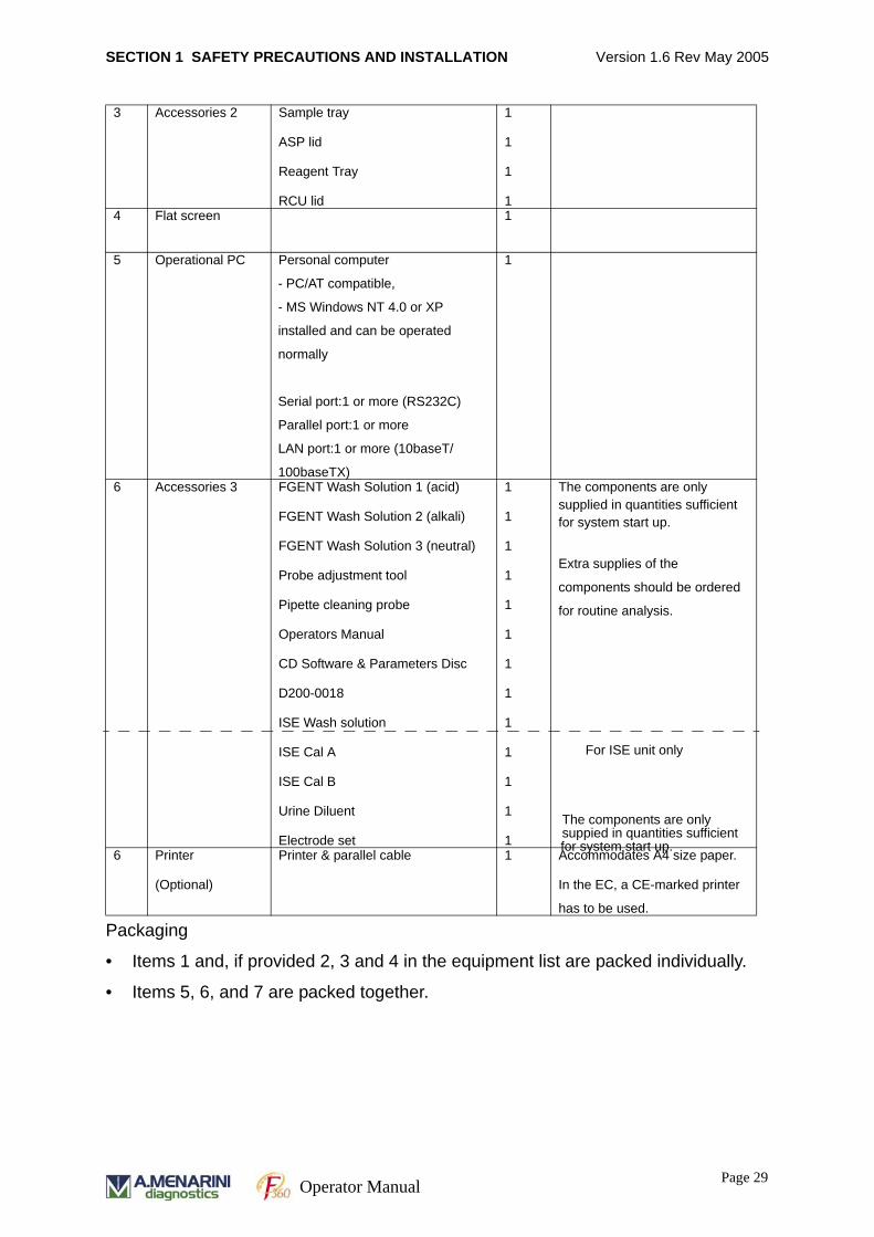
Packaging
• Items 1 and, if provided 2, 3 and 4 in the equipment list are packed individually.
• Items 5, 6, and 7 are packed together.
3 Accessories 2 Sample tray
ASP lid
Reagent Tray
RCU lid
1
1
1
14 Flat screen 1
5 Operational PC Personal computer
- PC/AT compatible,
- MS Windows NT 4.0 or XP
installed and can be operated
normally
Serial port:1 or more (RS232C)
Parallel port:1 or more
LAN port:1 or more (10baseT/
100baseTX)
1
6 Accessories 3 FGENT Wash Solution 1 (acid)
FGENT Wash Solution 2 (alkali)
FGENT Wash Solution 3 (neutral)
Probe adjustment tool
Pipette cleaning probe
Operators Manual
CD Software & Parameters Disc
D200-0018
ISE Wash solution
ISE Cal A
ISE Cal B
Urine Diluent
Electrode set
1
1
1
1
1
1
1
1
1
1
1
1
1
The components are only supplied in quantities sufficient for system start up.
Extra supplies of the
components should be ordered
for routine analysis.
6 Printer
(Optional)
Printer & parallel cable 1 Accommodates A4 size paper.
In the EC, a CE-marked printer
has to be used.
For ISE unit only
The components are onlysuppied in quantities sufficientfor system start up.
Page 29 Operator Manual

SECTION 1 SAFETY PRECAUTIONS AND INSTALLATION Version 1.6 Rev May 2005
Page 30
Operator Manual

SECTION 2 SYSTEM OVERVIEW Version 1.6 Rev May 2005
SECTION 2
SYSTEM OVERVIEW
Page 31Operator Manual
SECTION 2 SYSTEM OVERVIEW Version 1.6 Rev May 2005
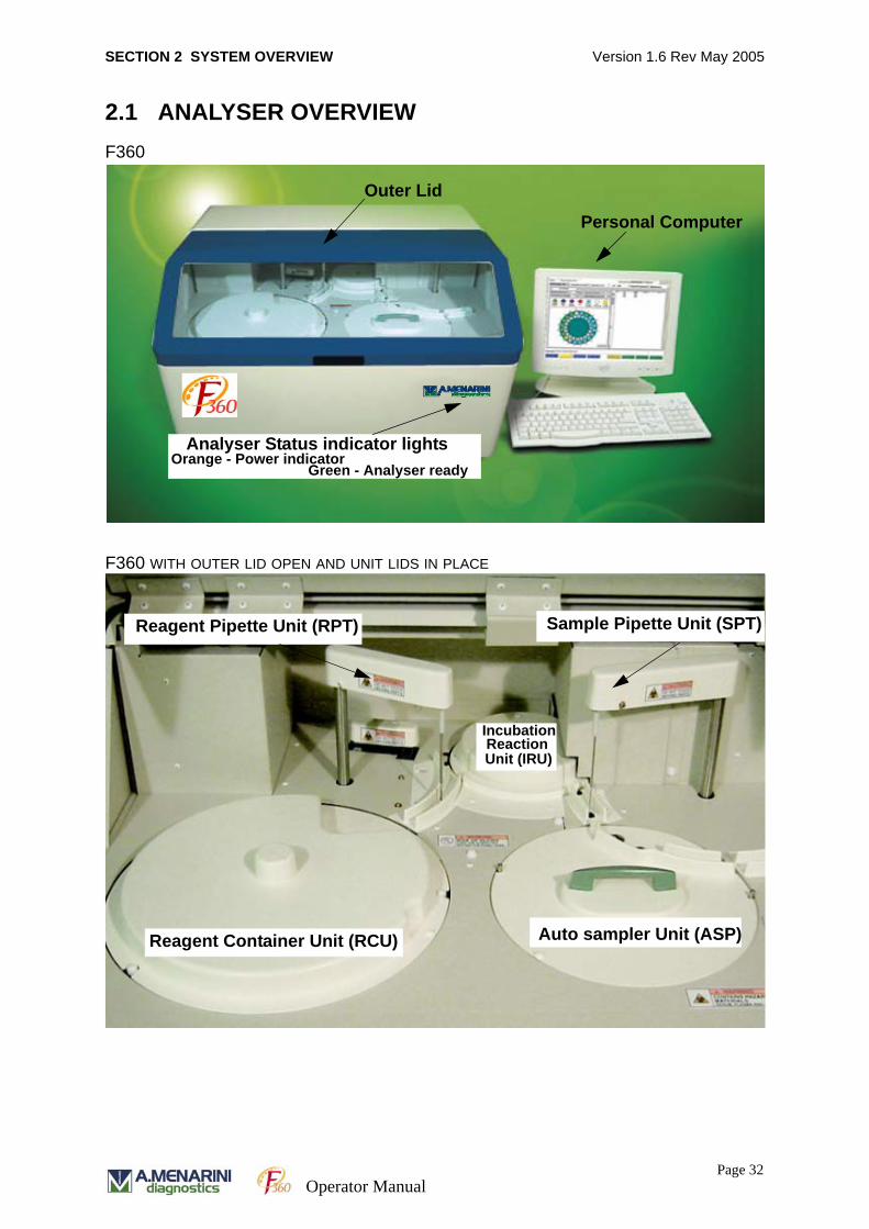
2.1 ANALYSER OVERVIEWF360
F360 WITH OUTER LID OPEN AND UNIT LIDS IN PLACE
Outer Lid
Personal Computer
Analyser Status indicator lightsOrange - Power indicator
Green - Analyser ready
Reagent Pipette Unit (RPT) Sample Pipette Unit (SPT)
IncubationReactionUnit (IRU)
Reagent Container Unit (RCU) Auto sampler Unit (ASP)
Page 32Operator Manual
SECTION 2 SYSTEM OVERVIEW Version 1.6 Rev May 2005
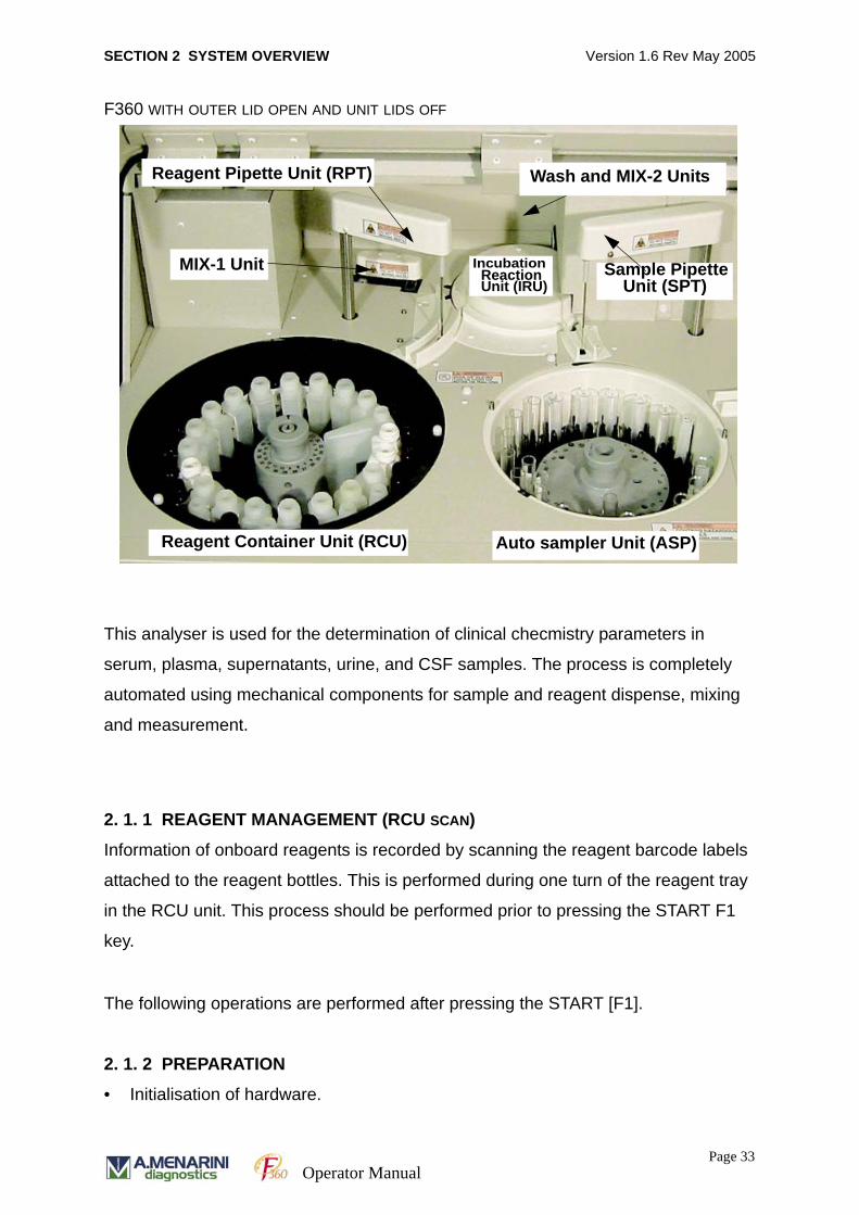
F360 WITH OUTER LID OPEN AND UNIT LIDS OFF
This analyser is used for the determination of clinical checmistry parameters in
serum, plasma, supernatants, urine, and CSF samples. The process is completely
automated using mechanical components for sample and reagent dispense, mixing
and measurement.
2. 1. 1 REAGENT MANAGEMENT (RCU SCAN)
Information of onboard reagents is recorded by scanning the reagent barcode labels
attached to the reagent bottles. This is performed during one turn of the reagent tray
in the RCU unit. This process should be performed prior to pressing the START F1
key.
The following operations are performed after pressing the START [F1].
2. 1. 2 PREPARATION
• Initialisation of hardware.
MIX-1 Unit
Reagent Container Unit (RCU) Auto sampler Unit (ASP)
Sample Pipette Unit (SPT)
Reagent Pipette Unit (RPT)
Incubation Reaction Unit (IRU)
Wash and MIX-2 Units
Page 33Operator Manual
SECTION 2 SYSTEM OVERVIEW Version 1.6 Rev May 2005
Each unit returns to its original position.
• Gain setting of absorbance meter.
Automatic gain control of halogen lamp is carried out.
• Prime
Nozzles are situated at their respective troughs. Each pump and syringe operates
and sends out solution into each line to expel air.
• Readout of bar code on the sample label (with barcode enabled only)
An inquiry is made to the host computer about measuring schedule on each sam-
ple tube in time for sampling.
2. 1. 3 FIRST REAGENT MEASUREMENT
The following processes describe the sequence of events for routine analysis,
assuming that all reagent, and system checks have been carried out.
• First reagent dispense
The reagent container unit (RCU) and the reaction table (IRU) rotate to the posi-
tion where the reagent is aspirated and dispensed by the reagent pipette unit
(RPT) into a cuvette on the IRU.
• Sample dispense
Sample is then aspirated and dispensed from the auto sampler unit (ASP) into the
cuvette on the reaction table (IRU) containing the pre-dispensed primary reagent.
The IRU rotates to the position where the sample pipette unit (SPT) dispenses the
sample.
• Stirring
The IRU then rotates to the position where the mixture in the cuvette is stirred
(MIX-1).
• Measurement of absorbance (1 - 13)
The IRU rotates to the position where the absorbance is measured. Thirteen
absorbance measurements of the cuvette are taken every 20 seconds and the
time course data of the first reagent is stored.
Page 34Operator Manual
SECTION 2 SYSTEM OVERVIEW Version 1.6 Rev May 2005
2. 1. 4 SECOND REAGENT MEASUREMENT
• Second reagent dispense
The reagent container unit (RCU) and the reaction table (IRU) rotate to the posi-
tion where the second reagent is aspirated and dispensed by the reagent pipette
unit (RPT) into the cuvette on the IRU which contains the primary reagent and
sample mixture.
• Stirring
The IRU then rotates to the position where the mixture in the cuvette is stirred
(MIX-2).
• Measurement of absorbance (14 - 26)
The IRU rotates to the position where the absorbance is measured. Thirteen
absorbance measurements of the cuvette are taken every 20 seconds and the
time course data of the second reagent is stored.
2. 1. 5 WASH
After assay completion the cuvette moves to the wash unit (WU). The reaction
solution is drained from the cuvette and the cuvette is then washed thoroughly.
2. 1. 6 EMERGENCY STOP
During routine analysis, an emergency interruption is possible by pressing [Control]
and [F2] keys simultaneously. The software will also interrupt routine operation when
there is a fault in the analyser.
ANALYSIS DATA WILL BE LOST when an emergency stop is initiated. The following
procedures should be followed before resuming operation:
1. The cause of the emergency stop must be resolved. For example, in case of the
user emergency stop due to the settings of erroneous measuring conditions, the
correct settings are required.
2. In the case of an automatic system emergency stop, lift the lid and check that
there are no items interfering with the mechanical operation of the equipment.
Page 35Operator Manual
SECTION 2 SYSTEM OVERVIEW Version 1.6 Rev May 2005
When the cause of emergency stop is unknown, contact Technical Support to
resolve the problem.
2. 1. 7 AUTOMATIC RERUN
When a sample concentration is greater or lower than the technical range of the
equipment and automatic reruns are enabled the sample is re-run (please see
Section 4.2 for detailed description of automatic re-runs). Rerun volumes are based
on pre-defined system settings for sample volume, diluent volume and diluted sample
volume for analysis. Sample dilution may be carried out using a defined diluent
according to the defined settings in the Chemistry Parameters screen. The analytical
result reported for the diluted sample is already corrected for the dilution.
2. 1. 8 REAGENT BLANK MEASUREMENT
The absorbance of a cuvette without sample is measured. Sample results may then
corrected with the reagent blank value.
2. 1. 9 WATER BLANK MEASUREMENT (CUVETTE CHECK)
The absorbance of a cuvette containing only water is measured. The result is used as
a guide for assessing the degree of staining on the cuvette.
The analyser will perform a cuvette check at the beginning of each run by washing the
cuvettes and then checking the absorbance measurement.
2. 1. 10 ISE MEASUREMENT
This measurement is carried out when the optional ISE unit is present in the analyser
and an ISE test is requested. Urine samples require a 1 in 10 dilution prior to analysis
and a dedicated urine diluent must be used. This diluent needs to be pre-registered
as a diluent reagent code in the SYSTEM PARAMETERS section and be present on
board the analyser to perform ISE tests on urine samples. ISE priming, cleaning and
calibration are performed via the Maintenance/ Sequence (F9) screen.
Page 36Operator Manual

SECTION 2 SYSTEM OVERVIEW Version 1.6 Rev May 2005
2.2 SYSTEM COMPONENTSThis section describes each component of the system in detail. Refer to ‘Analyser
Overview’ section for location of individual system components.
2. 2. 1 AUTOSAMPLER UNIT (ASP)
The auto sampler unit (ASP) consists of the removable turntable with a sample tube
rack and a sample barcode reader.
AUTOSAMPLER UNIT (ASP)
The ASP accommodates 40 sample tubes. Each sample is aspirated by the sample
pipette unit (SPT) and dispensed into a cuvette in the incubation reaction unit (IRU).
The sample pipette unit can dispense serum, plasma, supernatants, urine, and CSF.
The sample turntable rotates counter clockwise.
Aperture for barcode
Removable Turntable
Sample Tube Holder
Page 37Operator Manual
SECTION 2 SYSTEM OVERVIEW Version 1.6 Rev May 2005
2. 2. 1. 1 TURNTABLE
The sample tube with barcode label attached is inserted into the tube holding
mechanism. A total of 40 sample tubes can be accommodated (20 tubes on inner and
20 on the outer ring).
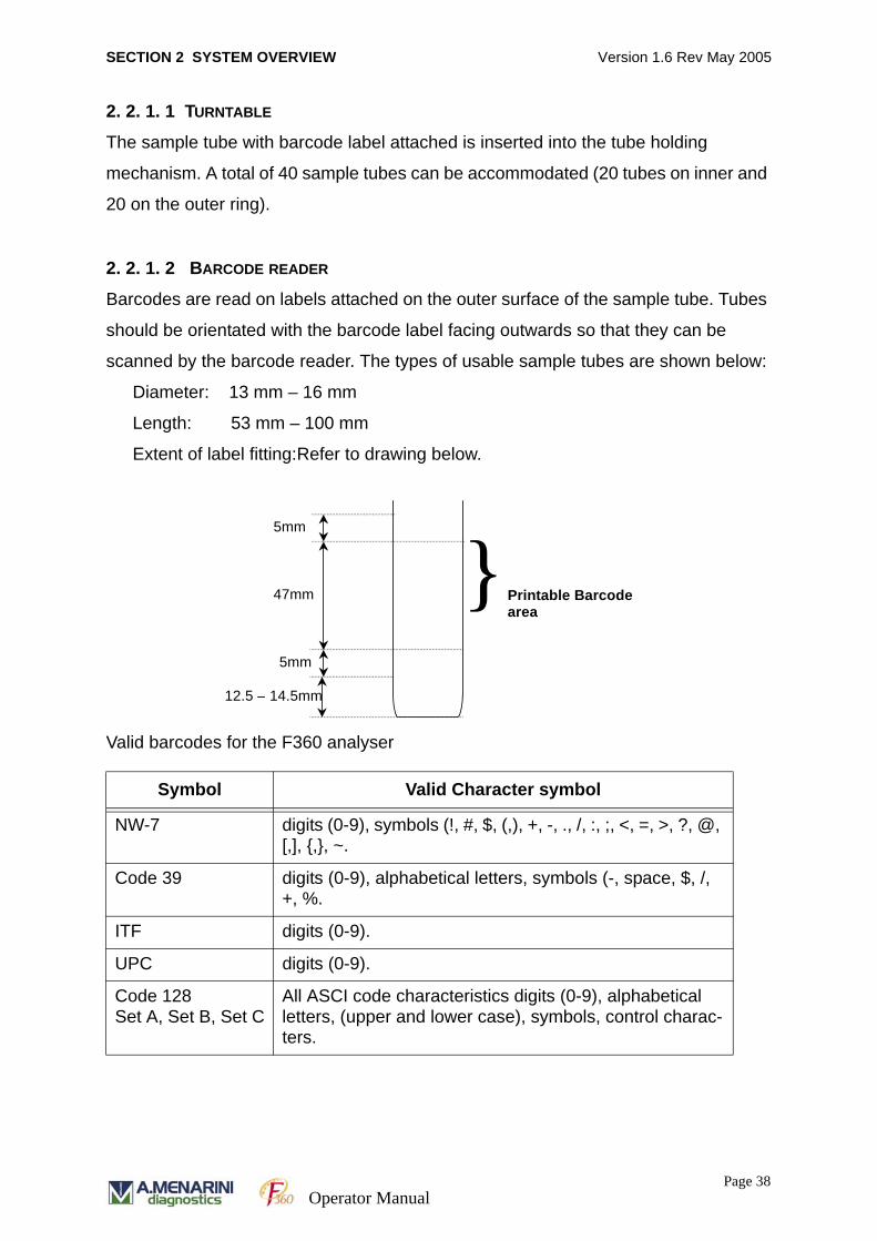
2. 2. 1. 2 BARCODE READER
Barcodes are read on labels attached on the outer surface of the sample tube. Tubes
should be orientated with the barcode label facing outwards so that they can be
scanned by the barcode reader. The types of usable sample tubes are shown below:
Diameter: 13 mm – 16 mm
Length: 53 mm – 100 mm
Extent of label fitting:Refer to drawing below.
Valid barcodes for the F360 analyser
Symbol Valid Character symbol
NW-7 digits (0-9), symbols (!, #, $, (,), +, -, ., /, :, ;, <, =, >, ?, @, [,], {,}, ~.
Code 39 digits (0-9), alphabetical letters, symbols (-, space, $, /, +, %.
ITF digits (0-9).
UPC digits (0-9).
Code 128Set A, Set B, Set C
All ASCI code characteristics digits (0-9), alphabetical letters, (upper and lower case), symbols, control charac-ters.
5mm
5mm
47mm
12.5 – 14.5mm
} Printable Barcode area
Page 38Operator Manual
SECTION 2 SYSTEM OVERVIEW Version 1.6 Rev May 2005
Allowable characters for sample number and patient ID:
Numerical characters 0 to 9
Alphabetical characters A to Z and a to z
Symbols !, ‘’, #, $, (, ), +, -, ., /, :, ;, <, =, >, ?, @, [, ],{, }, ~
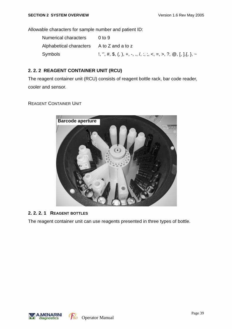
2. 2. 2 REAGENT CONTAINER UNIT (RCU)
The reagent container unit (RCU) consists of reagent bottle rack, bar code reader,
cooler and sensor.
REAGENT CONTAINER UNIT
2. 2. 2. 1 REAGENT BOTTLES
The reagent container unit can use reagents presented in three types of bottle.
Barcode aperture
Page 39Operator Manual
SECTION 2 SYSTEM OVERVIEW Version 1.6 Rev May 2005
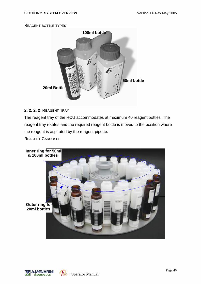
REAGENT BOTTLE TYPES
2. 2. 2. 2 REAGENT TRAY
The reagent tray of the RCU accommodates at maximum 40 reagent bottles. The
reagent tray rotates and the required reagent bottle is moved to the position where
the reagent is aspirated by the reagent pipette.
REAGENT CAROUSEL
100ml bottle
20ml Bottle
50ml bottle
& 100ml bottlesInner ring for 50ml
Outer ring for 20ml bottles
Page 40Operator Manual
SECTION 2 SYSTEM OVERVIEW Version 1.6 Rev May 2005
2. 2. 2. 3 COOLER
When the equipment is switched on, including during sleep mode, the temperature in
the RCU is controlled by the cooling power unit (CPU). A temperature sensor in the
RCU ensures that the temperature of the reagent is kept within the specified range.
The specified range is 8 -15ºC provided that the ambient temperature is between 15-
30ºC.
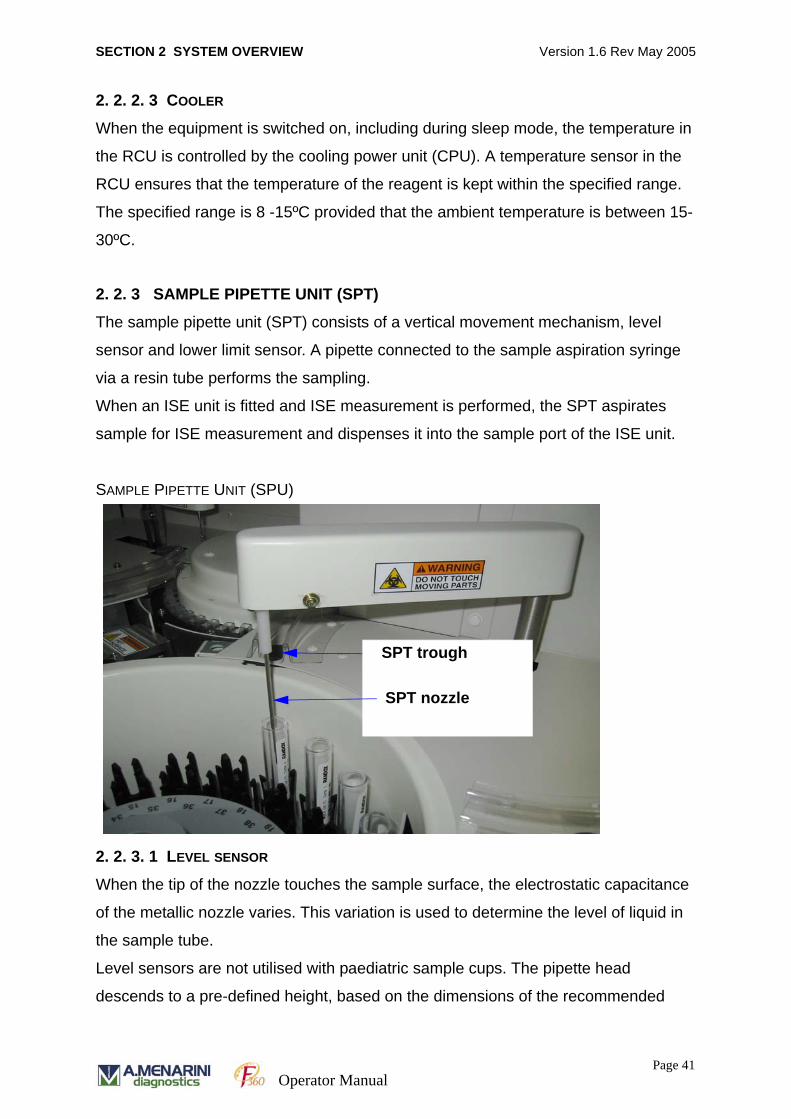
2. 2. 3 SAMPLE PIPETTE UNIT (SPT)
The sample pipette unit (SPT) consists of a vertical movement mechanism, level
sensor and lower limit sensor. A pipette connected to the sample aspiration syringe
via a resin tube performs the sampling.
When an ISE unit is fitted and ISE measurement is performed, the SPT aspirates
sample for ISE measurement and dispenses it into the sample port of the ISE unit.
SAMPLE PIPETTE UNIT (SPU)
2. 2. 3. 1 LEVEL SENSOR
When the tip of the nozzle touches the sample surface, the electrostatic capacitance
of the metallic nozzle varies. This variation is used to determine the level of liquid in
the sample tube.
Level sensors are not utilised with paediatric sample cups. The pipette head
descends to a pre-defined height, based on the dimensions of the recommended
SPT trough
SPT nozzle
Page 41Operator Manual
SECTION 2 SYSTEM OVERVIEW Version 1.6 Rev May 2005
sample cups and tubes. It is important that only the recommended sample cups and
tubes are used for analysis of small sample volumes.
2. 2. 3. 2 LOWER LIMIT SENSOR
The lower level detector will detect when the tip of the nozzle hits the bottom of the
sample cup due to insufficient sample volume. Downward pipette movement is then
prevented.
2. 2. 3. 3 SPT TROUGH
After sampling is completed, the tip of the SPT nozzle is washed with system water in
the SPT trough.
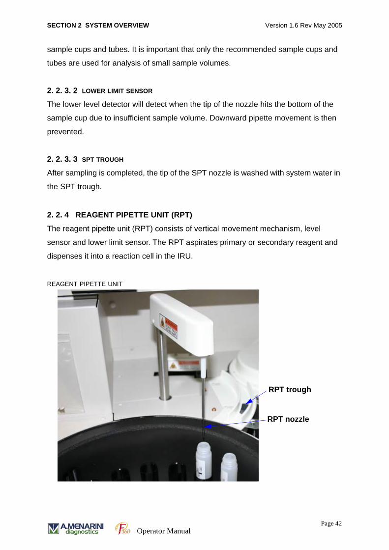
2. 2. 4 REAGENT PIPETTE UNIT (RPT)
The reagent pipette unit (RPT) consists of vertical movement mechanism, level
sensor and lower limit sensor. The RPT aspirates primary or secondary reagent and
dispenses it into a reaction cell in the IRU.
REAGENT PIPETTE UNIT
RPT trough
RPT nozzle
Page 42Operator Manual
SECTION 2 SYSTEM OVERVIEW Version 1.6 Rev May 2005
2. 2. 4. 1 LEVEL SENSOR
When the tip of the nozzle touches the reagent surface, the electrostatic capacitance
of the metallic nozzle varies. This variation is used to determine the level of liquid in
the reagent bottle.
2. 2. 4. 2 LOWER LIMIT SENSOR
The lower level detector will detect when the tip of the nozzle hits the bottom of the
reagent cup due to insufficient reagent volume. Downward pipette movement is then
prevented.
2. 2. 4. 3 RPT TROUGH
After dispensing is completed, the tip of the RPT nozzle is washed in the RPT trough.
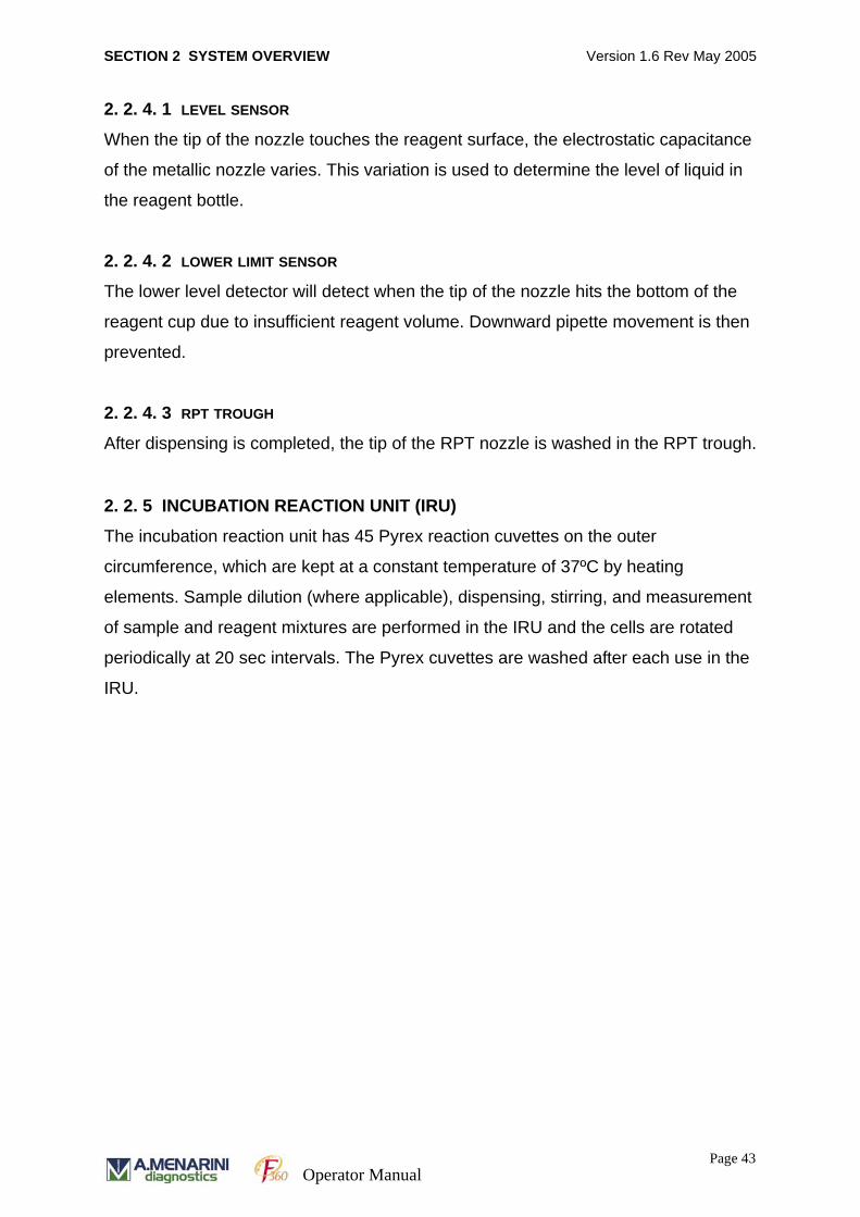
2. 2. 5 INCUBATION REACTION UNIT (IRU)
The incubation reaction unit has 45 Pyrex reaction cuvettes on the outer
circumference, which are kept at a constant temperature of 37ºC by heating
elements. Sample dilution (where applicable), dispensing, stirring, and measurement
of sample and reagent mixtures are performed in the IRU and the cells are rotated
periodically at 20 sec intervals. The Pyrex cuvettes are washed after each use in the
IRU.
Page 43Operator Manual
SECTION 2 SYSTEM OVERVIEW Version 1.6 Rev May 2005
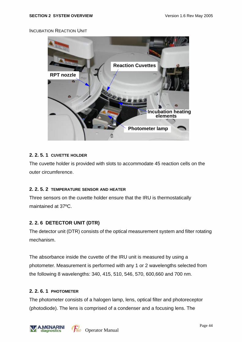
INCUBATION REACTION UNIT
2. 2. 5. 1 CUVETTE HOLDER
The cuvette holder is provided with slots to accommodate 45 reaction cells on the
outer circumference.
2. 2. 5. 2 TEMPERATURE SENSOR AND HEATER
Three sensors on the cuvette holder ensure that the IRU is thermostatically
maintained at 37ºC.
2. 2. 6 DETECTOR UNIT (DTR)
The detector unit (DTR) consists of the optical measurement system and filter rotating
mechanism.
The absorbance inside the cuvette of the IRU unit is measured by using a
photometer. Measurement is performed with any 1 or 2 wavelengths selected from
the following 8 wavelengths: 340, 415, 510, 546, 570, 600,660 and 700 nm.
2. 2. 6. 1 PHOTOMETER
The photometer consists of a halogen lamp, lens, optical filter and photoreceptor
(photodiode). The lens is comprised of a condenser and a focusing lens. The
RPT nozzle
Reaction Cuvettes
Photometer lamp
elementsIncubation heating
Page 44Operator Manual
SECTION 2 SYSTEM OVERVIEW Version 1.6 Rev May 2005
condenser lens converts the light from the halogen lamp into a collimated light beam
that is then focused through the focusing lens in the direction of the photoreceptor.
The photoreceptor converts the light passing through the solution in the reaction cell
into an electrical signal.
2. 2. 7 STIRRING UNIT (MIX-1 & MIX-2)
The analyser has two stirring units MIX-1 and MIX-2. (See location of MIX units on
main analyser photograph).
2. 2. 7. 1 MIX-1
After dispense of the sample and the first reagent into the reaction cell the liquid is
stirred by rotation of a paddle attached to the tip of the nozzle on the MIX-1 unit. The
tip of the stirrer nozzle is then washed in the MIX-1 trough with water.
2. 2. 7. 2 MIX-2
After dispense of the second reagent into the reaction cell the liquid is stirred by
rotation of a paddle attached to the tip of the nozzle on the MIX-2 unit. The tip of the
stirrer nozzle is then washed in the MIX-2 trough.
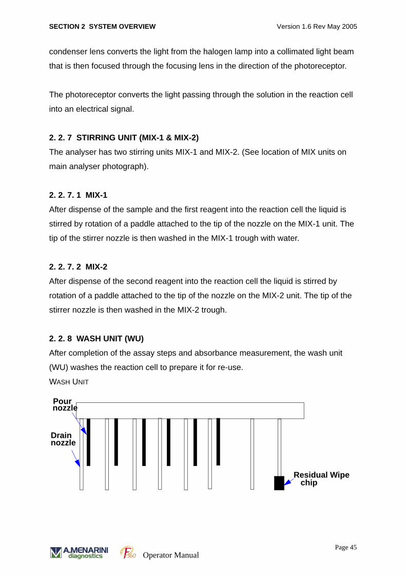
2. 2. 8 WASH UNIT (WU)
After completion of the assay steps and absorbance measurement, the wash unit
(WU) washes the reaction cell to prepare it for re-use.
WASH UNIT
Residual Wipe
Pour
Drain
chip
nozzle
nozzle
Page 45Operator Manual

SECTION 2 SYSTEM OVERVIEW Version 1.6 Rev May 2005
WASH UNIT
The wash unit consists of 6 dispense nozzles and 7 drain nozzles (including the final
drain nozzle), and a residual wipe chip. The nozzles move over the reaction cuvettes
and are then lowered into the cuvette by the vertical movement mechanism.
The solution inside the reaction cuvette is drained and then either pure water or wash
solution is dispensed into the cell to wash it. This is then aspirated from the cuvette
and the process repeated according to pre-set wash directions.
The drain nozzle is connected to the drain pump of the supply water unit (SWU) via a
resin tube. The dispense nozzle is connected to the syringe of the WPP unit via a
resin tube.
2. 2. 9 PUMP UNIT
The pump unit (PP) consists of 8 pumps, syringes and solenoid valves.
Six sets of nozzles
heads,drain (long)and pour (short) nozzle
Cuvette wipe block
MIX-2 Unit
each with two nozzle
Page 46Operator Manual
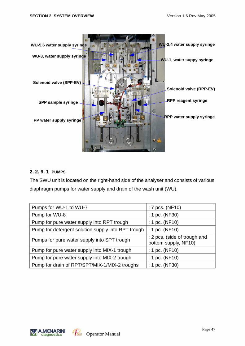
SECTION 2 SYSTEM OVERVIEW Version 1.6 Rev May 2005
2. 2. 9. 1 PUMPS
The SWU unit is located on the right-hand side of the analyser and consists of various
diaphragm pumps for water supply and drain of the wash unit (WU).
Pumps for WU-1 to WU-7 : 7 pcs. (NF10)Pump for WU-8 : 1 pc. (NF30)Pump for pure water supply into RPT trough : 1 pc. (NF10)Pump for detergent solution supply into RPT trough : 1 pc. (NF10)
Pumps for pure water supply into SPT trough : 2 pcs. (side of trough and bottom supply, NF10)
Pump for pure water supply into MIX-1 trough : 1 pc. (NF10)Pump for pure water supply into MIX-2 trough : 1 pc. (NF10)Pump for drain of RPT/SPT/MIX-1/MIX-2 troughs : 1 pc. (NF30)
WU-3, water supply syringe
Solenoid valve (SPP-EV)
SPP sample syringe
PP water supply syringe
WU-2,4 water supply syringe
WU-1, water suppy syringe
Solenoid valve (RPP-EV)
RPP reagent syringe
RPP water supply syringe
WU-5,6 water supply syringe
Page 47Operator Manual

SECTION 2 SYSTEM OVERVIEW Version 1.6 Rev May 2005
2. 2. 9. 2 SYRINGES
There are four supply syringes within the pump unit that supply water to the six
dispense nozzles on the wash unit. All four wash unit syringes are linked in their
operation.
There are an additional four syringes on the pump unit that include the SPP sample
syringe, SPP system water supply syringe, RPP reagent syringe and the RPP pure
water supply syringe.
WU-1 water supply syringe This syringe aspirates purified water from the water tank and dispenses via WU-1 nozzle into the cuvette.
WU-2,4 water supply syringe
This syringe aspirates purified water from the water tank and dispenses via WU-2 and 4 nozzles into the cuvette.
WU-3 water supply syringe This syringe aspirates purified water from the water tank and dispenses via WU-3 nozzle into the cuvette.
WU-5,6 water supply syringe
This syringe aspirates purified water from the water tank and dispenses via WU-5 and 6 nozzles into the cuvette.
SPP sample syringe This syringe aspirates sample via the SPT nozzle and dispenses it into the cuvette on the cuvette holder. (This syringe is linked with the SPP purified water supply syringe in its operation.)
SPP system water supply syringe
This syringe aspirates purified water from the system water tank to draw water into the SPP line. During sample dispense, the sample at the tip of the SPP nozzle is pushed out by the water. (This syringe is linked with the SPP sample syringe in its operation.)
RPP reagent syringe This syringe aspirates reagent via RPT nozzle and dispenses it into cuvettes on the cuvette holder. (This syringe is linked with the RPP pure water supply syringe in its operation.)
RPP pure water supply syringe
This syringe aspirates purified water from the system water tank to draw water into the RPT line. During reagent dispense, the reagent at the tip of the RPP nozzle is pushed out by the water. (This syringe is linked with the RPP sample syringe in its operation.)
Page 48Operator Manual

SECTION 2 SYSTEM OVERVIEW Version 1.6 Rev May 2005
2. 2. 9. 3 SOLENOID VALVE
The solenoid valve switches the syringe operation between aspiration and drain.
2. 2. 10 ELECTROLYTE MEASUREMENT UNIT
The electrolyte concentration (sodium, potassium, chloride) contained in blood serum,
plasma or urine is measured by the Ion Selective Electrode (ISE) unit, which is
located on the right-hand side of the analyser. This unit is optionally installed.
LOCATION OF ISE UNIT
ISE UNIT WITH DOOR OPEN
SPP-EV For switching between aspiration into and dispense from the SPP line.
RPP-EV For switching between aspiration into and dispense from the RPP line.
ISE unitAccess door to insert cal A for
ISE unitAccess door for
Sodium
Potassium
Chloride
Reference
ELECTRODES
Page 49Operator Manual
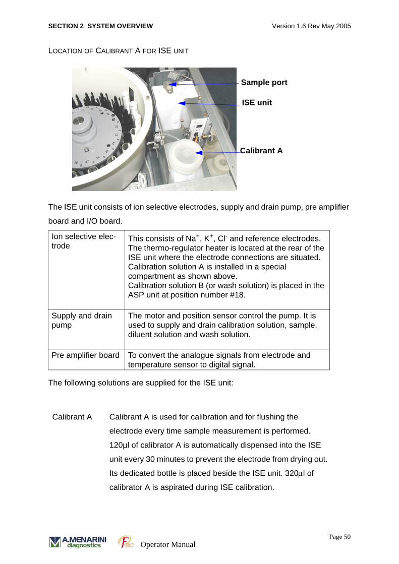
SECTION 2 SYSTEM OVERVIEW Version 1.6 Rev May 2005
LOCATION OF CALIBRANT A FOR ISE UNIT
The ISE unit consists of ion selective electrodes, supply and drain pump, pre amplifier
board and I/O board.
The following solutions are supplied for the ISE unit:
Ion selective elec-trode
This consists of Na+, K+, Cl- and reference electrodes. The thermo-regulator heater is located at the rear of the ISE unit where the electrode connections are situated.Calibration solution A is installed in a special compartment as shown above.Calibration solution B (or wash solution) is placed in the ASP unit at position number #18.
Supply and drain pump
The motor and position sensor control the pump. It is used to supply and drain calibration solution, sample, diluent solution and wash solution.
Pre amplifier board To convert the analogue signals from electrode and temperature sensor to digital signal.
Calibrant A Calibrant A is used for calibration and for flushing the
electrode every time sample measurement is performed.
120µl of calibrator A is automatically dispensed into the ISE
unit every 30 minutes to prevent the electrode from drying out.
Its dedicated bottle is placed beside the ISE unit. 320μl of
calibrator A is aspirated during ISE calibration.
ISE unit
Sample port
Calibrant A
Page 50Operator Manual
SECTION 2 SYSTEM OVERVIEW Version 1.6 Rev May 2005
Calibrant B This is used for calibration of the ISE unit.
500μl of calibrator B is placed in a sample cup at position
number 18 in the ASP tray. 200µl calibrator B is aspirated
during ISE calibration. Calibration is carried out at the
beginning of each day and at least every 8 hours.
Calibrant B is dispensed using the following menu options
• Select MAINTENANCE menu option from the job menu
• Select [SEQUENCE (F9)]
ISE Cleaning Solution
• ISE cleaning solution is dispensed into the unit to avoid
contamination of the electrode with protein. When
necessary, 600µl of cleaning solution is placed in a sample
cup at position number 18 in the ASP tray. ISE cleaning is
recommended at the end of the day via automatic sleep
function and at least every 8 hours if greater than 50
samples are processed per day. Cleaning solution is
dispensed using the following menu options.
NB: See section 9. 5. 2“ISE Cleaning” on page 324.
• Select MAINTENANCE menu option from the job menu
• Select [SEQUENCE (F9)]
Diluent Urine diluent is used to dilute urine samples 1 in 10.
Diluent is presented in a reagent bottle, which is placed on the
RCU unit. Approximately 315µl of diluent is required for the
dilution of each sample. The dilution is carried out using a
cuvette on the IRU unit and one cycle of chemistry analysis is
allocated to the dilution.
The diluent is pre-registered with a reagent code under the
SYSTEM PARAMETERS section of the job menu under
[SYSTEM (F9)].
Sampling Volume
100µl sample is aspirated for each ISE measurement.
Page 51Operator Manual
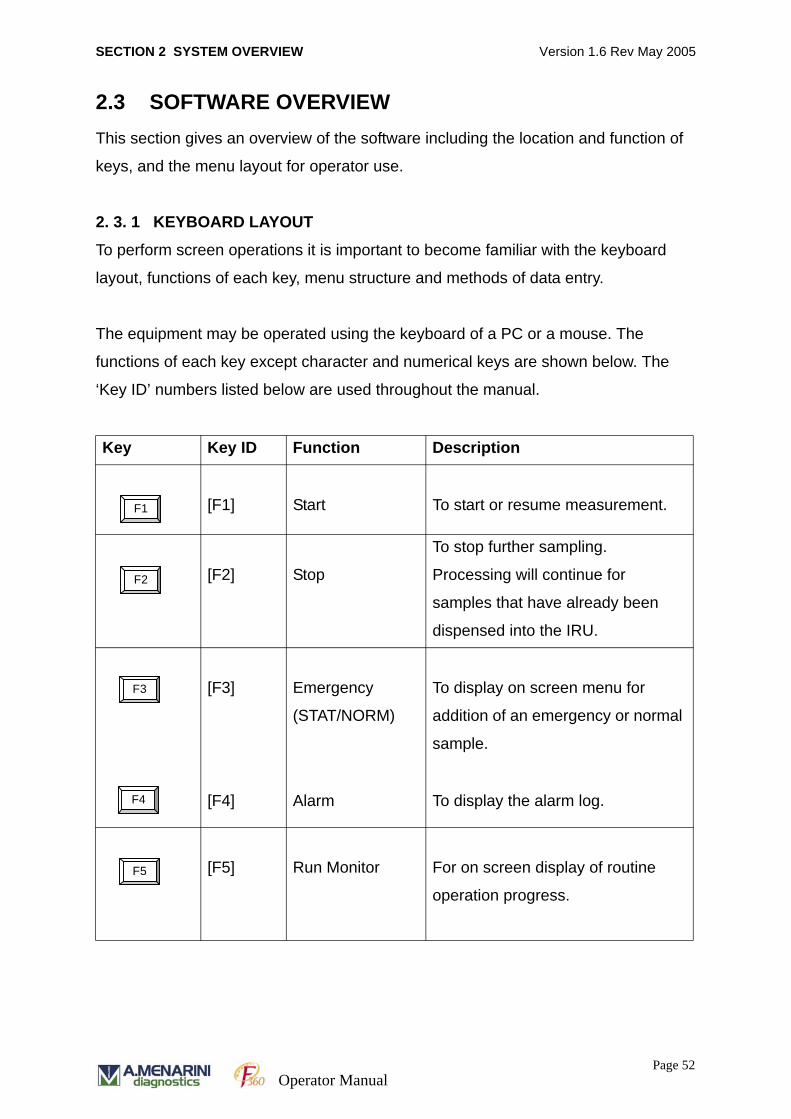
SECTION 2 SYSTEM OVERVIEW Version 1.6 Rev May 2005
2.3 SOFTWARE OVERVIEWThis section gives an overview of the software including the location and function of
keys, and the menu layout for operator use.
2. 3. 1 KEYBOARD LAYOUT
To perform screen operations it is important to become familiar with the keyboard
layout, functions of each key, menu structure and methods of data entry.
The equipment may be operated using the keyboard of a PC or a mouse. The
functions of each key except character and numerical keys are shown below. The
‘Key ID’ numbers listed below are used throughout the manual.
Key Key ID Function Description
[F1] Start To start or resume measurement.
[F2] Stop
To stop further sampling.
Processing will continue for
samples that have already been
dispensed into the IRU.
[F3] Emergency
(STAT/NORM)
To display on screen menu for
addition of an emergency or normal
sample.
[F4] Alarm To display the alarm log.
[F5] Run Monitor For on screen display of routine
operation progress.
F1
F2
F3
F4
F5
Page 52Operator Manual
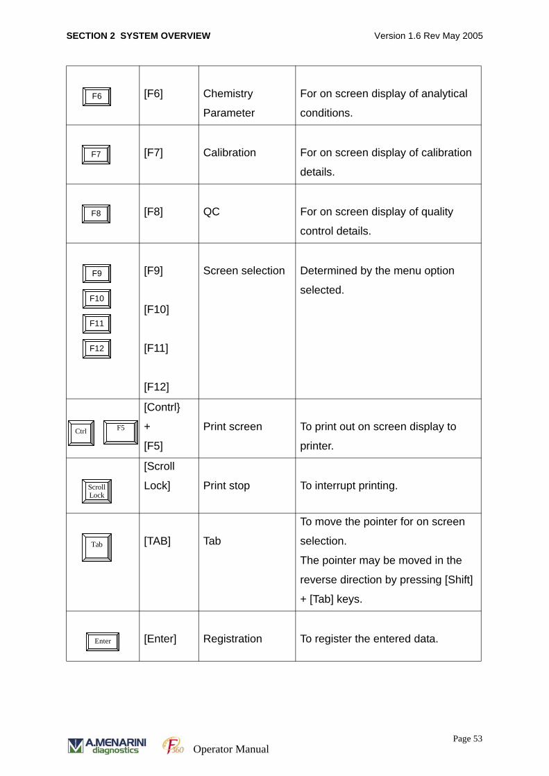
SECTION 2 SYSTEM OVERVIEW Version 1.6 Rev May 2005
[F6] Chemistry
Parameter
For on screen display of analytical
conditions.
[F7] Calibration For on screen display of calibration
details.
[F8] QC For on screen display of quality
control details.
[F9]
[F10]
[F11]
[F12]
Screen selection Determined by the menu option
selected.
[Contrl}
+
[F5]
Print screen To print out on screen display to
printer.
[Scroll
Lock] Print stop To interrupt printing.
[TAB] Tab
To move the pointer for on screen
selection.
The pointer may be moved in the
reverse direction by pressing [Shift]
+ [Tab] keys.
[Enter] Registration To register the entered data.
F6
F7
F8
F9
F10
F11
F12
F5 Ctrl
Scroll Lock
Tab
Enter
Page 53Operator Manual
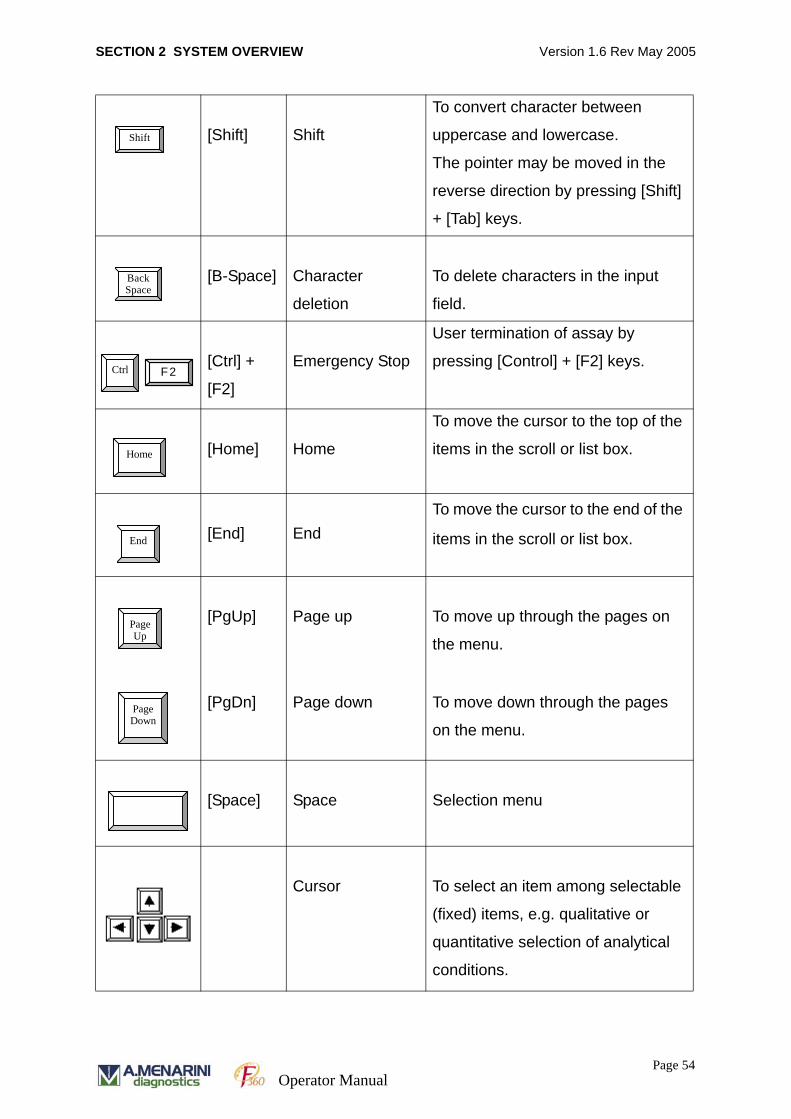
SECTION 2 SYSTEM OVERVIEW Version 1.6 Rev May 2005
[Shift] Shift
To convert character between
uppercase and lowercase.
The pointer may be moved in the
reverse direction by pressing [Shift]
+ [Tab] keys.
[B-Space] Character
deletion
To delete characters in the input
field.
[Ctrl] +
[F2]
Emergency Stop
User termination of assay by
pressing [Control] + [F2] keys.
[Home] Home
To move the cursor to the top of the
items in the scroll or list box.
[End] EndTo move the cursor to the end of the
items in the scroll or list box.
[PgUp] Page up To move up through the pages on
the menu.
[PgDn] Page down To move down through the pages
on the menu.
[Space] Space Selection menu
Cursor To select an item among selectable
(fixed) items, e.g. qualitative or
quantitative selection of analytical
conditions.
Shift
Back Space
Ctrl F2
Home
End
Page Up
Page Down
Page 54Operator Manual

SECTION 2 SYSTEM OVERVIEW Version 1.6 Rev May 2005
[ESC] Escape To close window. Esc
Page 55Operator Manual

SECTION 2 SYSTEM OVERVIEW Version 1.6 Rev May 2005
2. 3. 2 MENU STRUCTURE
Run monitor display
Page-1/2 : Test selectionPage-2/2 : Emergency test (when barcode enabled)
Page-1/2 : General informationPage-2/2 : Detailed information
Automatic Rerun selectionAutomatic Print-out selectionSerum Information selectionHost Communication Mode selectionPrime Mode selection
Page-1/2 : Chemistry Parameters for each MethodPage-2/2 : Serum Indices
Calculated test expression
Profile definition
Page-1/2 : Testing order definitionPage-2/2 : Print out order definition
Page-1/2 : Calibration settingPage-2/2 : Serial Dilution
Limit Checks (Duplicate, Sensitivity, Linearity, Prozone, Absorbance)Replicate Standard (Duplicate, Triplicate)Measurement of Reagent Blank at Full CalibrationMeasurement of Reagent Blank during Run
Multi Standard definition
Page-1/2 :QC chart-1,2 (Levey-Jennings Chart)Page-2/2 : QC chart-3 (Levey-Jennings Chart)
QC Results list
Definition of parameters for QC chart
Registration of Control Sample
Page-1/2 : Communication param. , Sample BCR param. , Print-header input, Reagent code registration.
Page-2/2 : Patient information definition, Number of replicate setting
Save to FD of mechanical parametersSave to FD of user parametersLoad parameters (former generation) from FD, Format FD
Reagent code of ISE diluent, ISE calibration resultInstrument factor for ISE
Measured results
Initialisation, Prime, Cuvette check, Cuvette wash, etcISE prime, ISE cleaning, ISE calibrationSensor testing
Page-1/2 : SPT/RPT wash, Wash program definitionWorking hour counter
Page-2/2 : Cuvette water blank check
Temperature.monitor of IRU & RCUDetector performance monitor
Auto start scheduling, Prep1/Prep2 settingAuto prime parameter (Short prime/Full prime interval set)
Run Monitor [F5] Run Monitor [F9]
Test Selection [F10]
Inventory [F11]
Condition [F12]
Chemistry [F9]
Calculate [F10]
Profile [F11]
Order [F12]
Calibration [F9]
Checks [F10]
Multi [F11]
Graphics [F9]
Measurements [F10]
QC Setting [F11]
Control [F12]
System [F9]
FD [F10]
ISE [F11]
Result [F12]
Chemistry Prm [F6]
Calibration [F7]
QC [F8]
System Parameters
Maintenance Sequence [F9]
Wash [F10]
Performance [F11]
Auto Start [F12]
Page 56Operator Manual
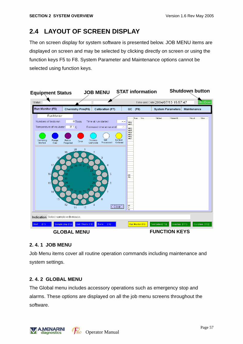
SECTION 2 SYSTEM OVERVIEW Version 1.6 Rev May 2005
2.4 LAYOUT OF SCREEN DISPLAYThe on screen display for system software is presented below. JOB MENU items are
displayed on screen and may be selected by clicking directly on screen or using the
function keys F5 to F8. System Parameter and Maintenance options cannot be
selected using function keys.
2. 4. 1 JOB MENU
Job Menu items cover all routine operation commands including maintenance and
system settings.
2. 4. 2 GLOBAL MENU
The Global menu includes accessory operations such as emergency stop and
alarms. These options are displayed on all the job menu screens throughout the
software.
JOB MENUEquipment Status Shutdown button
GLOBAL MENU FUNCTION KEYS
STAT information
Page 57Operator Manual
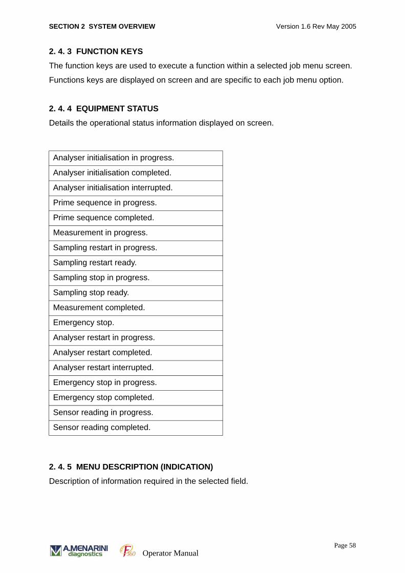
SECTION 2 SYSTEM OVERVIEW Version 1.6 Rev May 2005
2. 4. 3 FUNCTION KEYS
The function keys are used to execute a function within a selected job menu screen.
Functions keys are displayed on screen and are specific to each job menu option.
2. 4. 4 EQUIPMENT STATUS
Details the operational status information displayed on screen.
2. 4. 5 MENU DESCRIPTION (INDICATION)
Description of information required in the selected field.
Analyser initialisation in progress.
Analyser initialisation completed.
Analyser initialisation interrupted.
Prime sequence in progress.
Prime sequence completed.
Measurement in progress.
Sampling restart in progress.
Sampling restart ready.
Sampling stop in progress.
Sampling stop ready.
Measurement completed.
Emergency stop.
Analyser restart in progress.
Analyser restart completed.
Analyser restart interrupted.
Emergency stop in progress.
Emergency stop completed.
Sensor reading in progress.
Sensor reading completed.
Page 58Operator Manual

SECTION 2 SYSTEM OVERVIEW Version 1.6 Rev May 2005
2. 4. 6 PAGE NUMBER
Page number displayed.
2. 4. 7 STAT INFORMATION
When an emergency sample is being processed the message “STAT” (background is
red.) is displayed.
2. 4. 8 SHUTDOWN BUTTON
Pressing the Shutdown button will result in an on screen dialog box offering the
options to ‘Power Off’, ‘Sleep’ or to ‘Cancel’. Use ‘Power Off’ option to shut down the
analyser and restart PC.
Page 59Operator Manual

SECTION 2 SYSTEM OVERVIEW Version 1.6 Rev May 2005
Page 60Operator Manual
SECTION 3 SYSTEM PREPARATION AND ROUTINE ANALYSIS Version 1.6 Rev May 2005
SECTION 3
SYSTEM PREPARATION AND ROUTINE ANALYSIS
Page 61Operator Manual
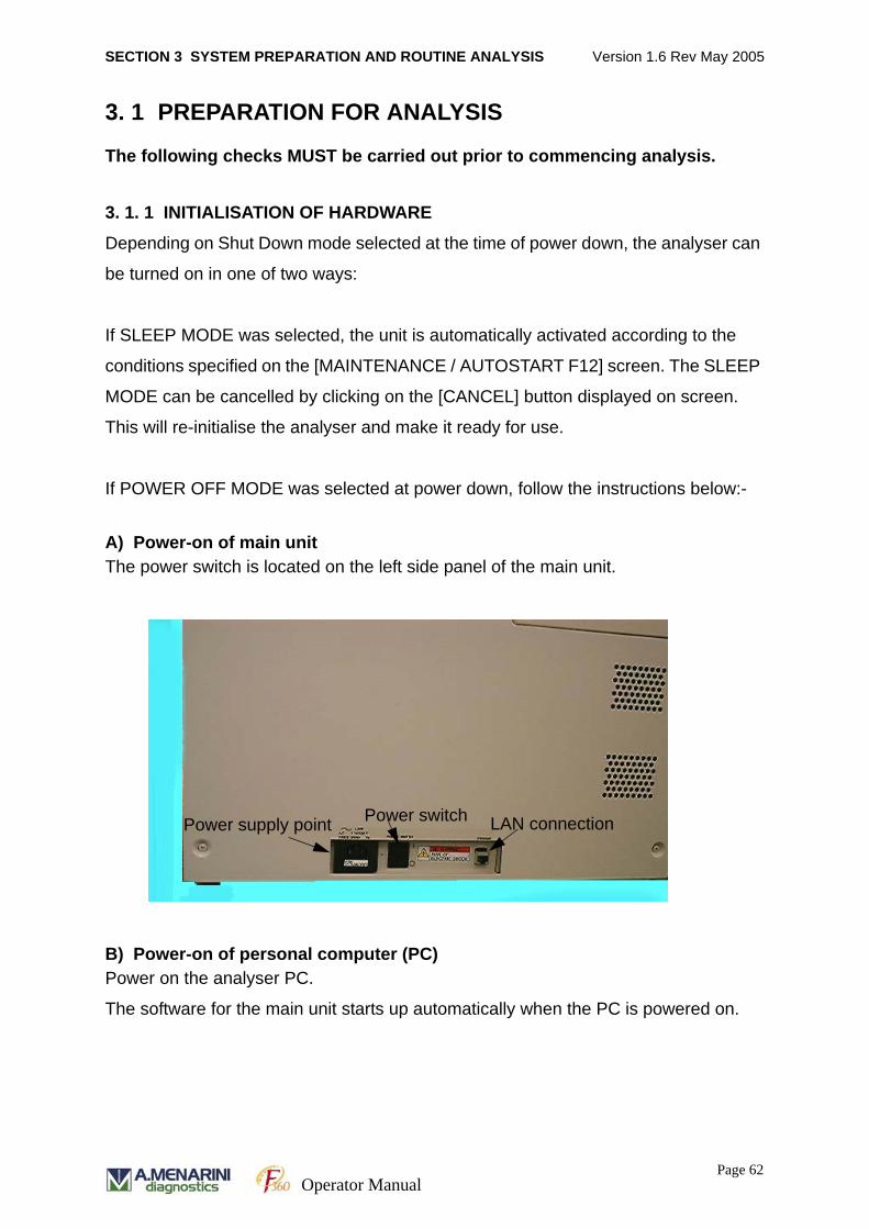
SECTION 3 SYSTEM PREPARATION AND ROUTINE ANALYSIS Version 1.6 Rev May 2005
3. 1 PREPARATION FOR ANALYSIS
The following checks MUST be carried out prior to commencing analysis.
3. 1. 1 INITIALISATION OF HARDWARE
Depending on Shut Down mode selected at the time of power down, the analyser can
be turned on in one of two ways:
If SLEEP MODE was selected, the unit is automatically activated according to the
conditions specified on the [MAINTENANCE / AUTOSTART F12] screen. The SLEEP
MODE can be cancelled by clicking on the [CANCEL] button displayed on screen.
This will re-initialise the analyser and make it ready for use.
If POWER OFF MODE was selected at power down, follow the instructions below:-
A) Power-on of main unitThe power switch is located on the left side panel of the main unit.
B) Power-on of personal computer (PC)Power on the analyser PC.
The software for the main unit starts up automatically when the PC is powered on.
Power supply point Power switch LAN connection
Page 62Operator Manual
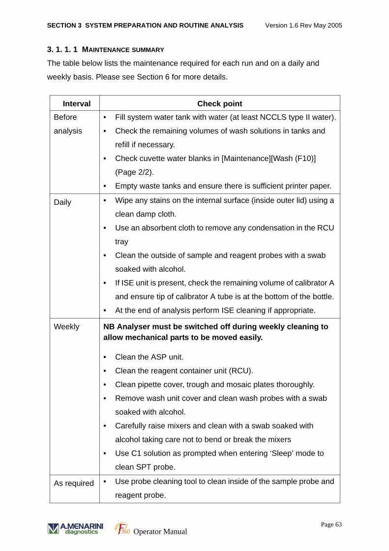
SECTION 3 SYSTEM PREPARATION AND ROUTINE ANALYSIS Version 1.6 Rev May 2005
3. 1. 1. 1 MAINTENANCE SUMMARY
The table below lists the maintenance required for each run and on a daily and
weekly basis. Please see Section 6 for more details.
Interval Check pointBefore
analysis
• Fill system water tank with water (at least NCCLS type II water).
• Check the remaining volumes of wash solutions in tanks and
refill if necessary.
• Check cuvette water blanks in [Maintenance][Wash (F10)]
(Page 2/2).
• Empty waste tanks and ensure there is sufficient printer paper.
Daily • Wipe any stains on the internal surface (inside outer lid) using a
clean damp cloth.
• Use an absorbent cloth to remove any condensation in the RCU
tray
• Clean the outside of sample and reagent probes with a swab
soaked with alcohol.
• If ISE unit is present, check the remaining volume of calibrator A
and ensure tip of calibrator A tube is at the bottom of the bottle.
• At the end of analysis perform ISE cleaning if appropriate.
Weekly NB Analyser must be switched off during weekly cleaning to allow mechanical parts to be moved easily.
• Clean the ASP unit.
• Clean the reagent container unit (RCU).
• Clean pipette cover, trough and mosaic plates thoroughly.
• Remove wash unit cover and clean wash probes with a swab
soaked with alcohol.
• Carefully raise mixers and clean with a swab soaked with
alcohol taking care not to bend or break the mixers
• Use C1 solution as prompted when entering ‘Sleep’ mode to
clean SPT probe.
As required • Use probe cleaning tool to clean inside of the sample probe and
reagent probe.
Page 63Operator Manual
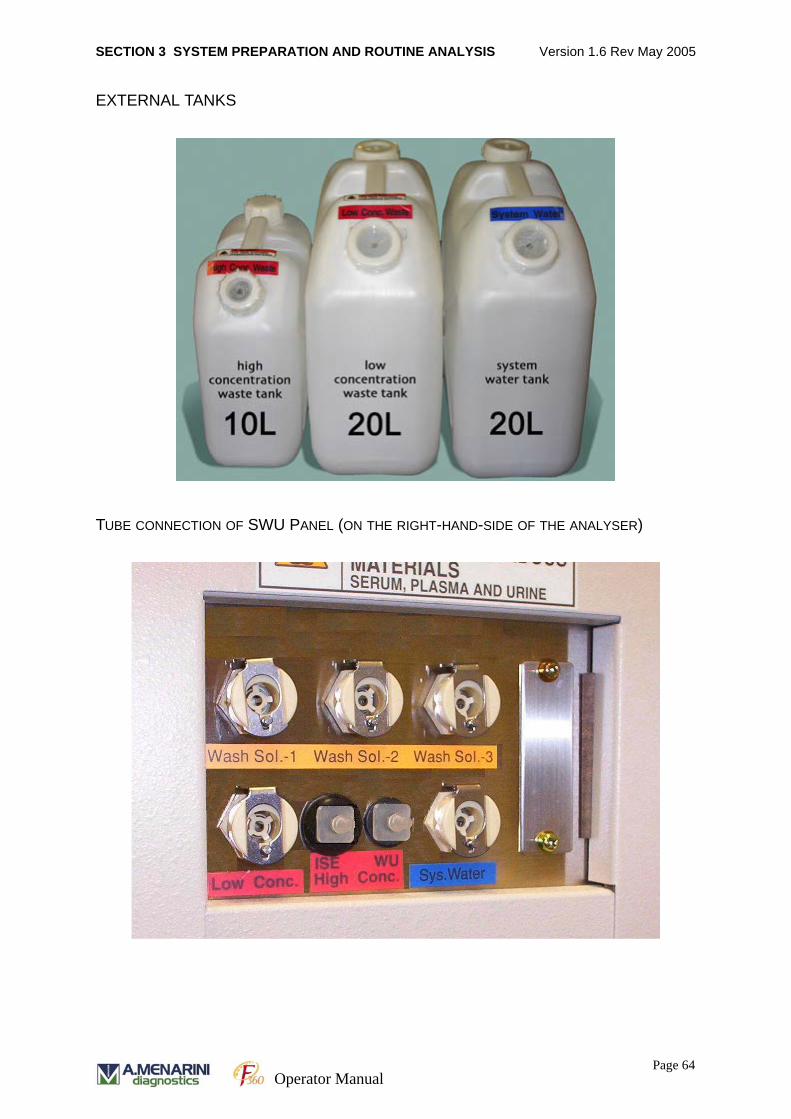
SECTION 3 SYSTEM PREPARATION AND ROUTINE ANALYSIS Version 1.6 Rev May 2005
EXTERNAL TANKS
TUBE CONNECTION OF SWU PANEL (ON THE RIGHT-HAND-SIDE OF THE ANALYSER)
Page 64Operator Manual
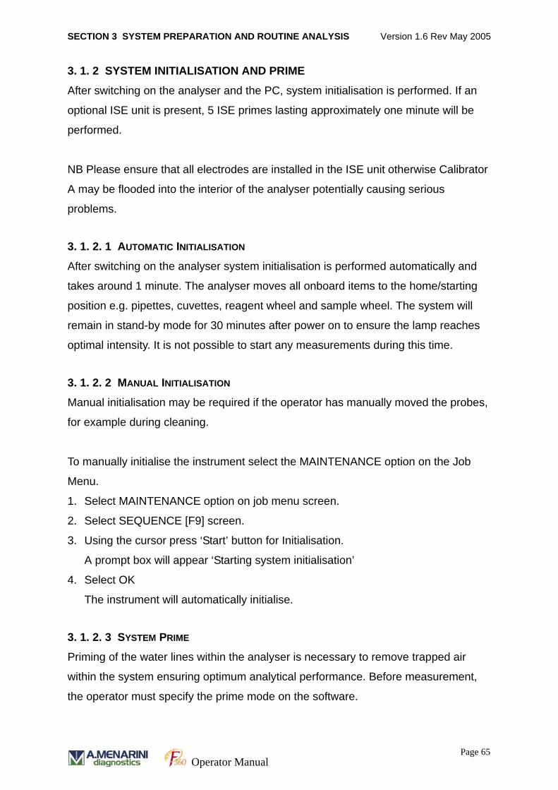
SECTION 3 SYSTEM PREPARATION AND ROUTINE ANALYSIS Version 1.6 Rev May 2005
3. 1. 2 SYSTEM INITIALISATION AND PRIME
After switching on the analyser and the PC, system initialisation is performed. If an
optional ISE unit is present, 5 ISE primes lasting approximately one minute will be
performed.
NB Please ensure that all electrodes are installed in the ISE unit otherwise Calibrator
A may be flooded into the interior of the analyser potentially causing serious
problems.
3. 1. 2. 1 AUTOMATIC INITIALISATION
After switching on the analyser system initialisation is performed automatically and
takes around 1 minute. The analyser moves all onboard items to the home/starting
position e.g. pipettes, cuvettes, reagent wheel and sample wheel. The system will
remain in stand-by mode for 30 minutes after power on to ensure the lamp reaches
optimal intensity. It is not possible to start any measurements during this time.
3. 1. 2. 2 MANUAL INITIALISATION
Manual initialisation may be required if the operator has manually moved the probes,
for example during cleaning.
To manually initialise the instrument select the MAINTENANCE option on the Job
Menu.
1. Select MAINTENANCE option on job menu screen.
2. Select SEQUENCE [F9] screen.
3. Using the cursor press ‘Start’ button for Initialisation.
A prompt box will appear ‘Starting system initialisation’
4. Select OK
The instrument will automatically initialise.
3. 1. 2. 3 SYSTEM PRIME
Priming of the water lines within the analyser is necessary to remove trapped air
within the system ensuring optimum analytical performance. Before measurement,
the operator must specify the prime mode on the software.
Page 65Operator Manual
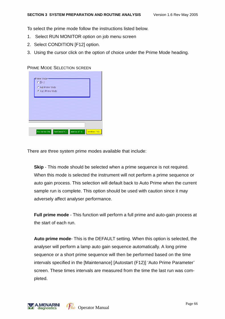
SECTION 3 SYSTEM PREPARATION AND ROUTINE ANALYSIS Version 1.6 Rev May 2005
To select the prime mode follow the instructions listed below.
1. Select RUN MONITOR option on job menu screen
2. Select CONDITION [F12] option.
3. Using the cursor click on the option of choice under the Prime Mode heading.
PRIME MODE SELECTION SCREEN
There are three system prime modes available that include:
Skip - This mode should be selected when a prime sequence is not required.
When this mode is selected the instrument will not perform a prime sequence or
auto gain process. This selection will default back to Auto Prime when the current
sample run is complete. This option should be used with caution since it may
adversely affect analyser performance.
Full prime mode - This function will perform a full prime and auto-gain process at
the start of each run.
Auto prime mode- This is the DEFAULT setting. When this option is selected, the
analyser will perform a lamp auto gain sequence automatically. A long prime
sequence or a short prime sequence will then be performed based on the time
intervals specified in the [Maintenance] [Autostart (F12)] ‘Auto Prime Parameter’
screen. These times intervals are measured from the time the last run was com-
pleted.
Page 66Operator Manual
SECTION 3 SYSTEM PREPARATION AND ROUTINE ANALYSIS Version 1.6 Rev May 2005
LONG PRIME MODE SEQUENCE
Note: Total time taken for long prime sequence is 8 mins 12 secs (492 secs).
SHORT PRIME MODE SEQUENCE
Note: Total time taken for short prime sequence is 60 secs (x10 primes) 30 secs
(x1 prime) seconds.
To view the Auto Prime Parameter screen follow the instructions below:
1. Select MAINTENANCE option on job menu screen
2. Select AUTOSTART [F12] option. The operator can view the default settings
for prime sequences.
Pump or syringe name Operating period
SWU MX1 Pump for Mix-1 trough ON:18 sec
SWU MX2 Pump for Mix-2 trough ON:16 sec
SWU Water Pump for SPT trough ON: 3 sec
SPP-S1 Syringe for SPP unit Water discharge: 1500µl x 10 times
RPT-water1 Pump for RPT trough ON: 3 sec
RPT-water2 Pump for RPT trough ON: 3 sec
RPT-detergent Pump for RPT trough ON: 3 sec
RPP Syringe for RPP unit Water discharge: 2000µl x 10 times
Pump or syringe name Operating period
SWU MX1 Pump for Mix-1 trough ON:1 sec
SWU MX2 Pump for Mix-2 trough ON:1 sec
SWU Water Pump for SPT trough ON: 1 sec
SPP-S1 Syringe for SPP unit Water discharge: 1500µl x 1 time
RPT-water1 Pump for RPT trough ON: 1 sec
RPT-water2 Pump for RPT trough ON: 1 sec
RPT-detergent Pump for RPT trough ON: 1 sec
RPP Syringe for RPP unit Water discharge: 2000µl x 1 time
Page 67Operator Manual
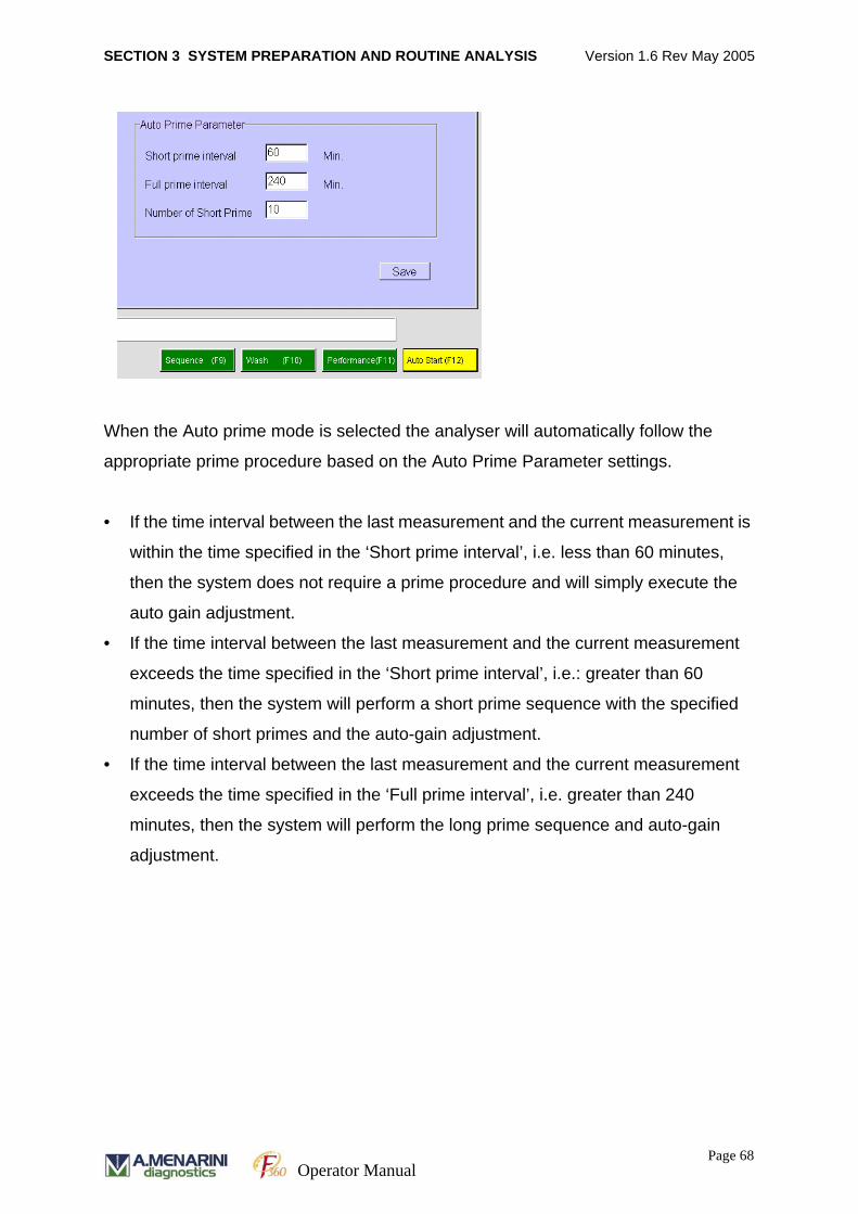
SECTION 3 SYSTEM PREPARATION AND ROUTINE ANALYSIS Version 1.6 Rev May 2005
When the Auto prime mode is selected the analyser will automatically follow the
appropriate prime procedure based on the Auto Prime Parameter settings.
• If the time interval between the last measurement and the current measurement is
within the time specified in the ‘Short prime interval’, i.e. less than 60 minutes,
then the system does not require a prime procedure and will simply execute the
auto gain adjustment.
• If the time interval between the last measurement and the current measurement
exceeds the time specified in the ‘Short prime interval’, i.e.: greater than 60
minutes, then the system will perform a short prime sequence with the specified
number of short primes and the auto-gain adjustment.
• If the time interval between the last measurement and the current measurement
exceeds the time specified in the ‘Full prime interval’, i.e. greater than 240
minutes, then the system will perform the long prime sequence and auto-gain
adjustment.
Page 68Operator Manual
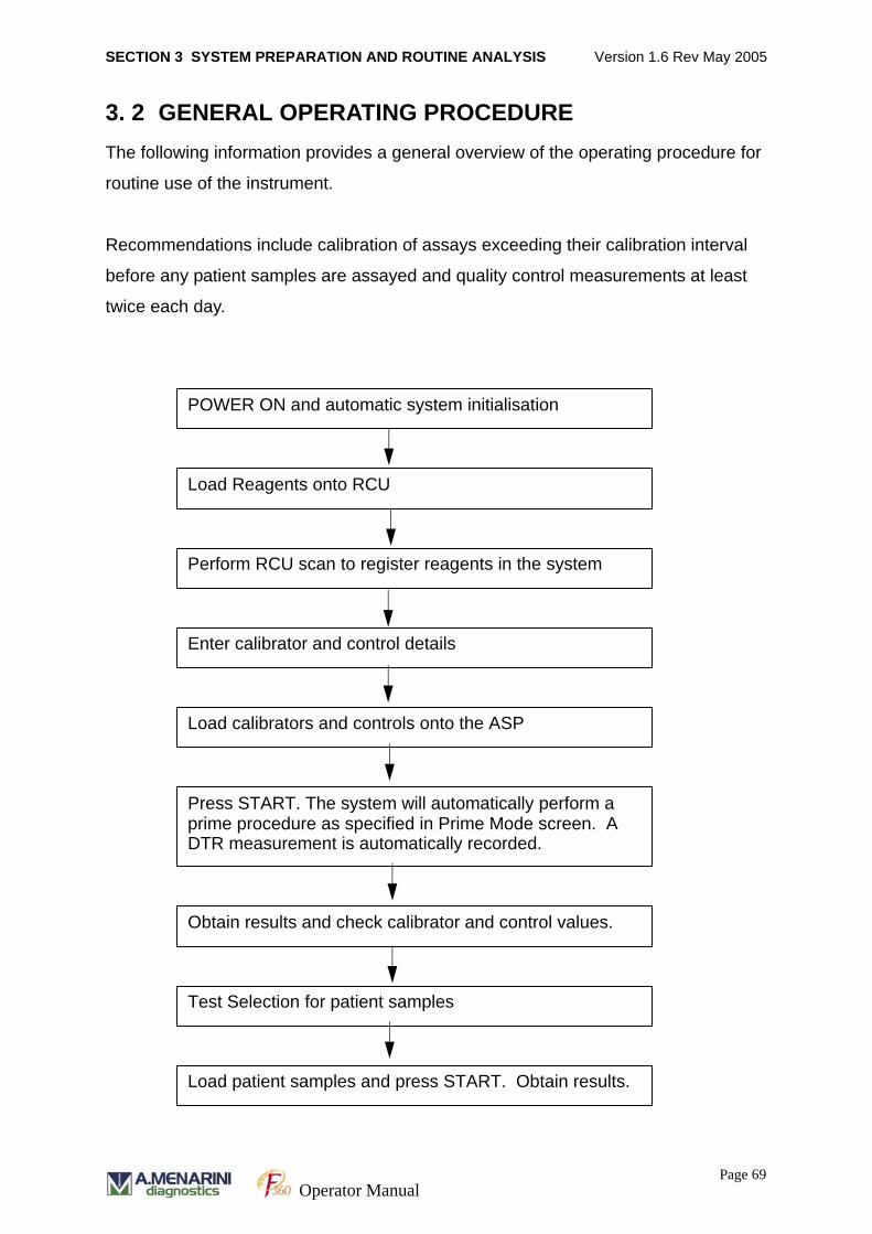
SECTION 3 SYSTEM PREPARATION AND ROUTINE ANALYSIS Version 1.6 Rev May 2005
3. 2 GENERAL OPERATING PROCEDUREThe following information provides a general overview of the operating procedure for
routine use of the instrument.
Recommendations include calibration of assays exceeding their calibration interval
before any patient samples are assayed and quality control measurements at least
twice each day.
POWER ON and automatic system initialisation
Load Reagents onto RCU
Perform RCU scan to register reagents in the system
Enter calibrator and control details
Test Selection for patient samples
Load calibrators and controls onto the ASP
Press START. The system will automatically perform a prime procedure as specified in Prime Mode screen. A DTR measurement is automatically recorded.
Obtain results and check calibrator and control values.
Load patient samples and press START. Obtain results.
Page 69Operator Manual
SECTION 3 SYSTEM PREPARATION AND ROUTINE ANALYSIS Version 1.6 Rev May 2005
3. 2. 1 LOAD REAGENT/ DILUENTS AND WASH SOLUTIONS
Reagents, diluents and wash solutions for analysis are located in the reagent
carousel. Up to 40 bottles in total can be stored in the cooled RCU unit.
• The reagent carousel is removed from the RCU and reagents, diluents and
wash solutions are placed in the carousel.
• Bottle caps MUST BE REMOVED before placing bottles in the carousel.
• 50 ml or 100 ml bottles are inserted on the inner ring of the carousel
• 20 ml bottles are inserted into bottle holders on the outer ring of the carousel.
• Bottles must be inserted into the holders in a position that enables the barcode to
be read.
• The reagent carousel is replaced in the RCU and the carousel is turned until the
guide pin fits into the specified position. The RCU lid is then replaced.
The analyser will only function if the lids for the RCU and ASP are correctly
placed on the analyser.
3. 2. 2 REGISTRATION OF REAGENTS, DILUENTS AND WASH SOLUTIONS
3. 2. 2. 1 REGISTRATION OF BARCODED (CLOSED CHANNEL) BOTTLES
Details of A. MENARINI Diagnostics closed channel reagents are pre-registered in
the software. [See Appendix G for details of how to use the Chemistry Parameter
Importing Software to load assay settings into the analyser software].
After loading the bottles in the reagent carousel, initiate a barcode scan as below to
register the reagent bottles on the carousel. The system will then offer test options
based on the reagents registered.
1. Select RUN MONITOR [F5] on the job menu
2. Select INVENTORY [F11] on the function keys.
3. Select the ‘RCU SCAN’ button.
4. Press START on the message box and the reagent registration will proceed.
Once complete, the software will display reagent inventory screen complete with
details based on the bottles located in the RCU.
Page 70Operator Manual

SECTION 3 SYSTEM PREPARATION AND ROUTINE ANALYSIS Version 1.6 Rev May 2005
The position and number of tests possible for each assay is displayed. If there is a
problem with the reagent a colour coded warning will be displayed.
1 Red - Insufficient reagent inventory
2. Pink - Reagent expired
3. Yellow - On board stability period exceeded
(1) and (2) will remove the relevant test from the [Run Monitor] [Test Select (F5)]
screen but (3) will allow the test to be performed with all results obtained flagged
‘STB’ to indicate the stability period has been exceeded. Please note that expired
reagents (2) cannot be used on the analyser.
If a reagent bottle is not located on the RCU, does not have a barcode or the barcode
is obstructed from the reader, the analyser will not assign a reagent position on the
carousel and will not offer the test parameter to the user on the test selection screen.
Furthermore, the parameter will not be available on the test selection screen if a wash
or diluent is enabled in the chemistry parameters but is not on board the analyser or
does not have a readable barcode.
Page 71Operator Manual
SECTION 3 SYSTEM PREPARATION AND ROUTINE ANALYSIS Version 1.6 Rev May 2005
If the barcode label is unreadable due to damage it may be necessary to enter the
barcode number printed on the label below the barcode manually.
Manual Input of barcode information
1. Select RUN MONITOR [F5] on the job menu
2. Select INVENTORY [F11] on the function keys.
3. Select Page 2/2 on the screen.
4. Select the RCU position by clicking on the position on screen. To delete
previous reagent details, click on the DELETE button and then SAVE.
5. Double click on the ‘Barcode’ column for the desired position to enable entry of the
barcode number. Type number exactly as it appears on the barcode label
and press RETURN to confirm. Pre-programmed details will automatically
appear on screen.
6. Click on SAVE to store the details.
7. To re-set a reagent volume (open channel barcodes only), click on the reagent
volume field and click on VOLUME RESET button. The reagent volume is re-
set to full volume.
Please note: with open channel reagents the stability term is not reset by using
the ‘Volume Reset’ button.
8. ‘Stability term’ is displayed for each reagent and represents the number of days
stability remaining for the reagent. When the reagent has exceeded the stability
term the information is highlighted yellow.
9. Click on the SAVE button.
Page 72Operator Manual
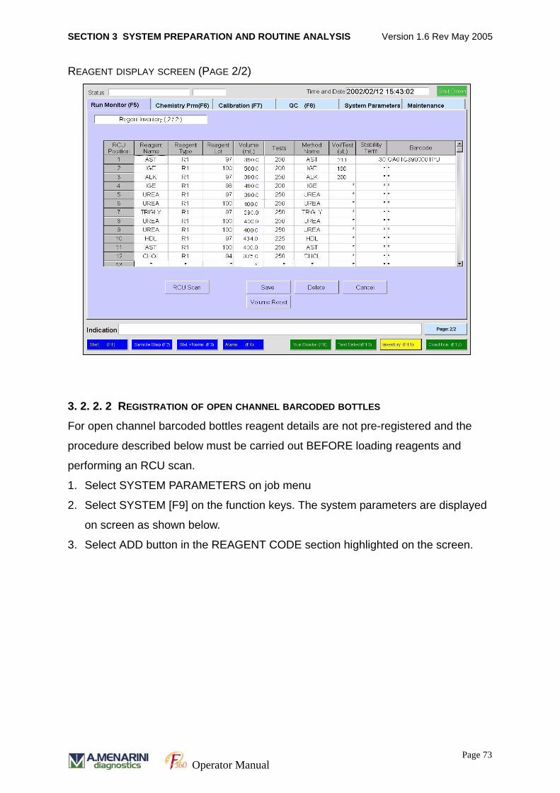
SECTION 3 SYSTEM PREPARATION AND ROUTINE ANALYSIS Version 1.6 Rev May 2005
REAGENT DISPLAY SCREEN (PAGE 2/2)
3. 2. 2. 2 REGISTRATION OF OPEN CHANNEL BARCODED BOTTLES
For open channel barcoded bottles reagent details are not pre-registered and the
procedure described below must be carried out BEFORE loading reagents and
performing an RCU scan.
1. Select SYSTEM PARAMETERS on job menu
2. Select SYSTEM [F9] on the function keys. The system parameters are displayed
on screen as shown below.
3. Select ADD button in the REAGENT CODE section highlighted on the screen.
Page 73Operator Manual
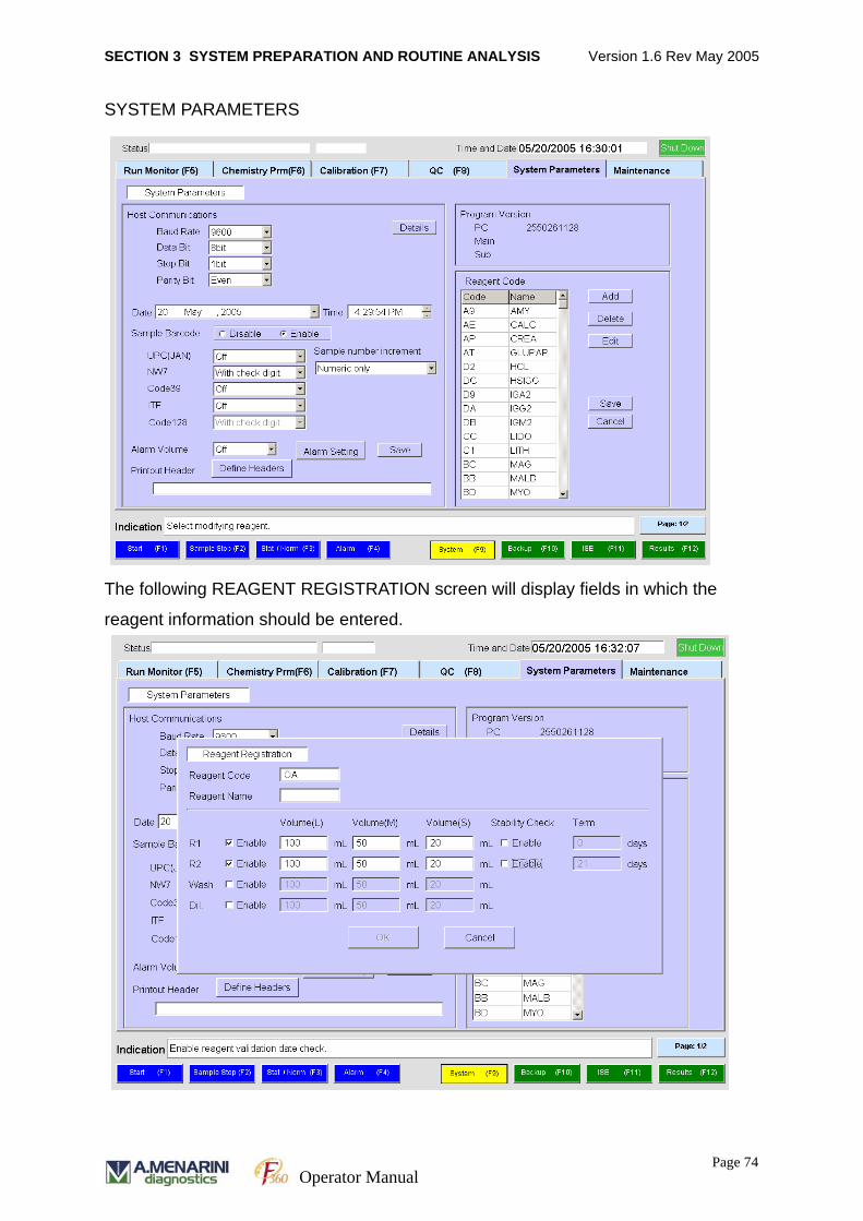
SECTION 3 SYSTEM PREPARATION AND ROUTINE ANALYSIS Version 1.6 Rev May 2005
SYSTEM PARAMETERS
The following REAGENT REGISTRATION screen will display fields in which the
reagent information should be entered.
Page 74Operator Manual
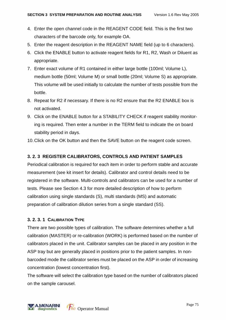
SECTION 3 SYSTEM PREPARATION AND ROUTINE ANALYSIS Version 1.6 Rev May 2005
4. Enter the open channel code in the REAGENT CODE field. This is the first two
characters of the barcode only, for example OA.
5. Enter the reagent description in the REAGENT NAME field (up to 6 characters).
6. Click the ENABLE button to activate reagent fields for R1, R2, Wash or Diluent as
appropriate.
7. Enter exact volume of R1 contained in either large bottle (100ml; Volume L),
medium bottle (50ml; Volume M) or small bottle (20ml; Volume S) as appropriate.
This volume will be used initially to calculate the number of tests possible from the
bottle.
8. Repeat for R2 if necessary. If there is no R2 ensure that the R2 ENABLE box is
not activated.
9. Click on the ENABLE button for a STABILITY CHECK if reagent stability monitor-
ing is required. Then enter a number in the TERM field to indicate the on board
stability period in days.
10.Click on the OK button and then the SAVE button on the reagent code screen.
3. 2. 3 REGISTER CALIBRATORS, CONTROLS AND PATIENT SAMPLES
Periodical calibration is required for each item in order to perform stable and accurate
measurement (see kit insert for details). Calibrator and control details need to be
registered in the software. Multi-controls and calibrators can be used for a number of
tests. Please see Section 4.3 for more detailed description of how to perform
calibration using single standards (S), multi standards (MS) and automatic
preparation of calibration dilution series from a single standard (SS).
3. 2. 3. 1 CALIBRATION TYPE
There are two possible types of calibration. The software determines whether a full
calibration (MASTER) or re-calibration (WORK) is performed based on the number of
calibrators placed in the unit. Calibrator samples can be placed in any position in the
ASP tray but are generally placed in positions prior to the patient samples. In non-
barcoded mode the calibrator series must be placed on the ASP in order of increasing
concentration (lowest concentration first).
The software will select the calibration type based on the number of calibrators placed
on the sample carousel.
Page 75Operator Manual
SECTION 3 SYSTEM PREPARATION AND ROUTINE ANALYSIS Version 1.6 Rev May 2005
• Full calibration (MASTER)
A Full calibration is carried out using all calibrators and the results are used to
update the master calibration curve. The calibration curve produced with full cali-
bration is the ‘Master calibration curve’. We recommend that a full calibration is
carried out for each assay after it has exceeded its defined calibration interval.
• Re-calibration (WORK)
The work calibration curve is updated using one or more selected calibrators. The
calibration curve produced with re-calibration is the ‘Work calibration curve’. This
curve is used to calculate the final result. In most cases the WORK and MASTER
curves will be the same unless recalibration is carried out. However we do not rec-
ommend re-calibrating with less than the full number of calibrators.
3. 2. 3. 2 CALIBRATION FOR DIFFERENT REAGENT LOTS
It is possible to store 2 different calibration curves in the analyser that correspond to
different lots of reagent. These are stored as ‘New’ and ‘Old’ calibration curves.
When a full calibration is first carried out the reagent lots used to generate the curve
are displayed under ‘Lot No (R1)’ and ‘Lot No (R2)’ fields on the [Calibration]
[Calibration (F9)] screen. Since this is the first calibration the reagent lots are marked
as ‘New’. If another calibration is performed using the same or different lot numbers of
reagent the most recent calibration is then displayed as ‘New’ and the previous
calibration is moved to ’Old’. Switch between viewing the ‘New’ and ‘Old’ calibrations
by using the ‘Change Lot’ button.
3. 2. 3. 3 DEFINING CALIBRATOR CONCENTRATION
Before calibration is performed, concentration values of each calibrator must be
entered in the software as described in this section.
When a new round of measurement is initiated, the software checks that a valid
calibration is available for the reagent lots registered in the inventory. If a valid
calibration is not available the results are displayed with a ‘CTR’ flag.
Page 76Operator Manual
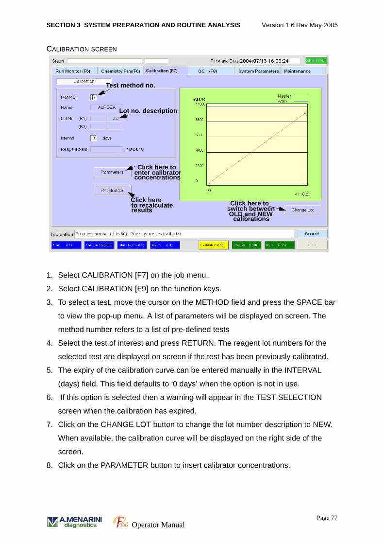
SECTION 3 SYSTEM PREPARATION AND ROUTINE ANALYSIS Version 1.6 Rev May 2005
CALIBRATION SCREEN
1. Select CALIBRATION [F7] on the job menu.
2. Select CALIBRATION [F9] on the function keys.
3. To select a test, move the cursor on the METHOD field and press the SPACE bar
to view the pop-up menu. A list of parameters will be displayed on screen. The
method number refers to a list of pre-defined tests
4. Select the test of interest and press RETURN. The reagent lot numbers for the
selected test are displayed on screen if the test has been previously calibrated.
5. The expiry of the calibration curve can be entered manually in the INTERVAL
(days) field. This field defaults to ‘0 days’ when the option is not in use.
6. If this option is selected then a warning will appear in the TEST SELECTION
screen when the calibration has expired.
7. Click on the CHANGE LOT button to change the lot number description to NEW.
When available, the calibration curve will be displayed on the right side of the
screen.
8. Click on the PARAMETER button to insert calibrator concentrations.
Test method no.
Lot no. description
Click here toenter calibrator concentrations
Click hereto recalculateresults
Click here toswitch betweenOLD and NEW
calibrations
Page 77Operator Manual
SECTION 3 SYSTEM PREPARATION AND ROUTINE ANALYSIS Version 1.6 Rev May 2005
9. Move the cursor to the required field and enter the calibrator concentrations in the
‘CONC’ column. The WORK and MASTER columns will automatically display the
absorbance measurements obtained during the previous calibration.
10.Click on the drop down arrow in the CALCULATION field to select the calibration
curve equation required for measurement. Click on the required equation type and
press RETURN.
11. Click on the CALCULATE button to save the details and display the calibration
curve.
Calibrator concentrations must be entered for each test parameter.
Page 78Operator Manual
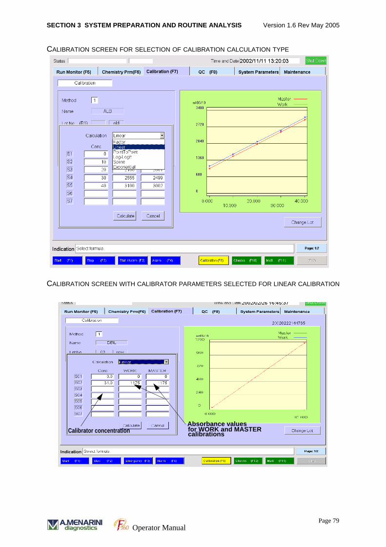
SECTION 3 SYSTEM PREPARATION AND ROUTINE ANALYSIS Version 1.6 Rev May 2005
CALIBRATION SCREEN FOR SELECTION OF CALIBRATION CALCULATION TYPE
CALIBRATION SCREEN WITH CALIBRATOR PARAMETERS SELECTED FOR LINEAR CALIBRATION
Absorbance values for WORK and MASTERcalibrationsCalibrator concentration
Page 79Operator Manual
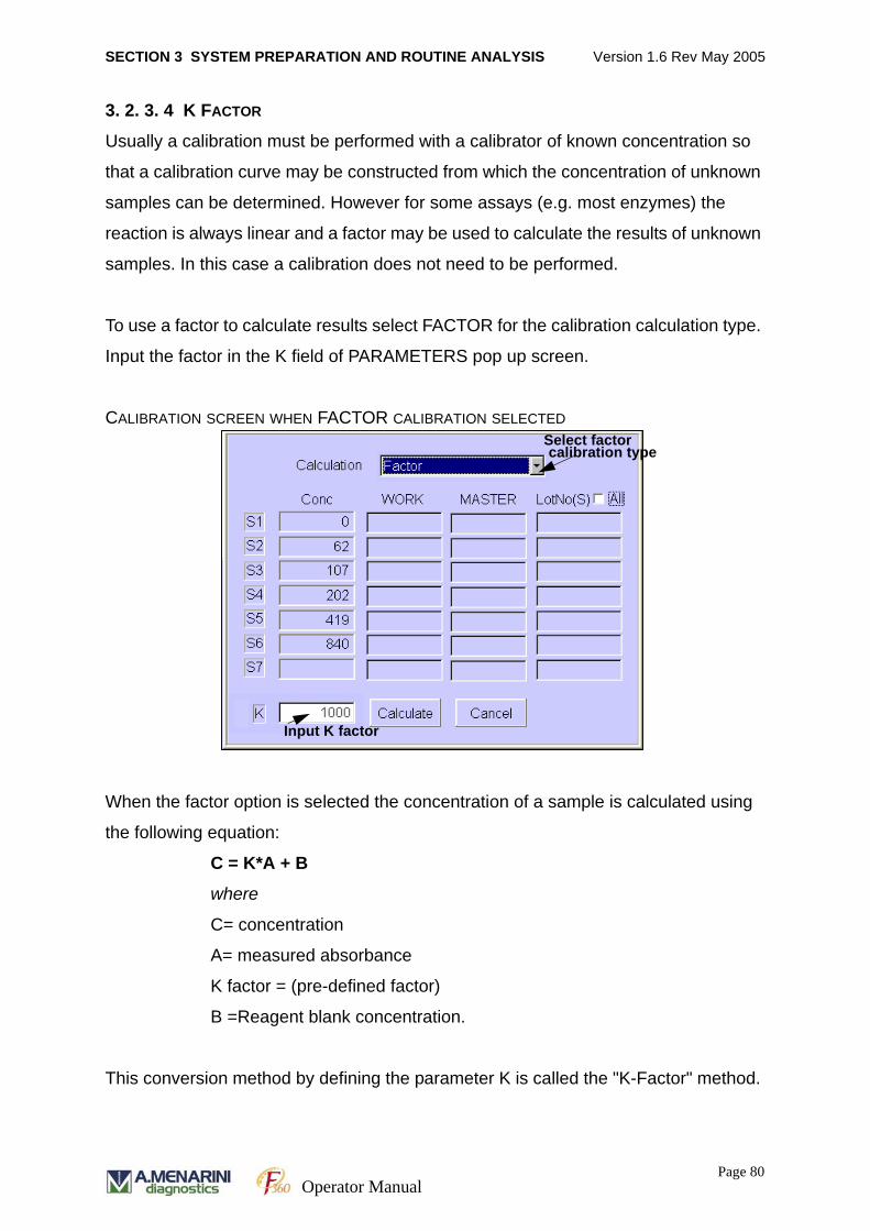
SECTION 3 SYSTEM PREPARATION AND ROUTINE ANALYSIS Version 1.6 Rev May 2005
3. 2. 3. 4 K FACTOR
Usually a calibration must be performed with a calibrator of known concentration so
that a calibration curve may be constructed from which the concentration of unknown
samples can be determined. However for some assays (e.g. most enzymes) the
reaction is always linear and a factor may be used to calculate the results of unknown
samples. In this case a calibration does not need to be performed.
To use a factor to calculate results select FACTOR for the calibration calculation type.
Input the factor in the K field of PARAMETERS pop up screen.
CALIBRATION SCREEN WHEN FACTOR CALIBRATION SELECTED
When the factor option is selected the concentration of a sample is calculated using
the following equation:
C = K*A + B
where
C= concentration
A= measured absorbance
K factor = (pre-defined factor)
B =Reagent blank concentration.
This conversion method by defining the parameter K is called the "K-Factor" method.
Select factorcalibration type
Input K factor
Page 80Operator Manual
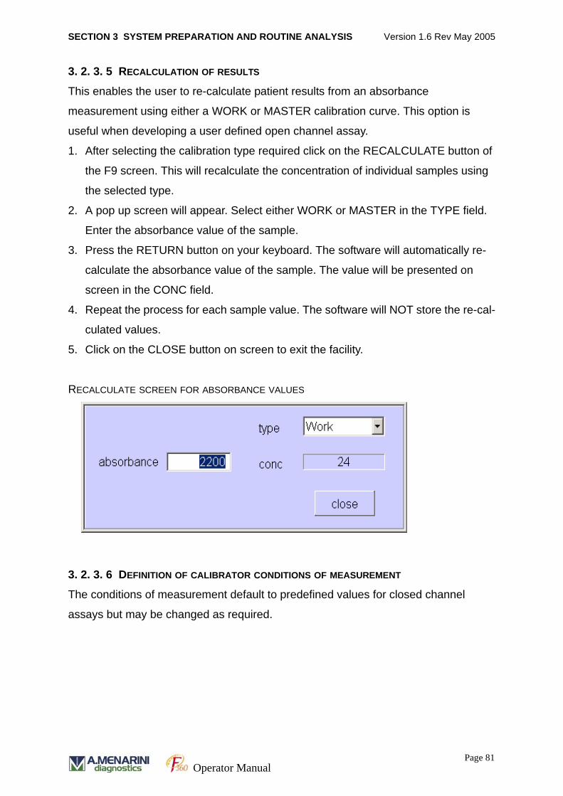
SECTION 3 SYSTEM PREPARATION AND ROUTINE ANALYSIS Version 1.6 Rev May 2005
3. 2. 3. 5 RECALCULATION OF RESULTS
This enables the user to re-calculate patient results from an absorbance
measurement using either a WORK or MASTER calibration curve. This option is
useful when developing a user defined open channel assay.
1. After selecting the calibration type required click on the RECALCULATE button of
the F9 screen. This will recalculate the concentration of individual samples using
the selected type.
2. A pop up screen will appear. Select either WORK or MASTER in the TYPE field.
Enter the absorbance value of the sample.
3. Press the RETURN button on your keyboard. The software will automatically re-
calculate the absorbance value of the sample. The value will be presented on
screen in the CONC field.
4. Repeat the process for each sample value. The software will NOT store the re-cal-
culated values.
5. Click on the CLOSE button on screen to exit the facility.
RECALCULATE SCREEN FOR ABSORBANCE VALUES
3. 2. 3. 6 DEFINITION OF CALIBRATOR CONDITIONS OF MEASUREMENT
The conditions of measurement default to predefined values for closed channel
assays but may be changed as required.
Page 81Operator Manual
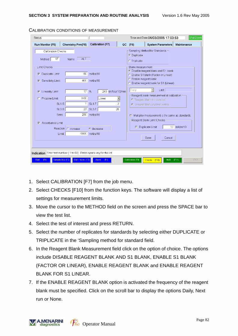
SECTION 3 SYSTEM PREPARATION AND ROUTINE ANALYSIS Version 1.6 Rev May 2005
CALIBRATION CONDITIONS OF MEASUREMENT
1. Select CALIBRATION [F7] from the job menu.
2. Select CHECKS [F10] from the function keys. The software will display a list of
settings for measurement limits.
3. Move the cursor to the METHOD field on the screen and press the SPACE bar to
view the test list.
4. Select the test of interest and press RETURN.
5. Select the number of replicates for standards by selecting either DUPLICATE or
TRIPLICATE in the ‘Sampling method for standard field.
6. In the Reagent Blank Measurement field click on the option of choice. The options
include DISABLE REAGENT BLANK AND S1 BLANK, ENABLE S1 BLANK
(FACTOR OR LINEAR), ENABLE REAGENT BLANK and ENABLE REAGENT
BLANK FOR S1 LINEAR.
7. If the ENABLE REAGENT BLANK option is activated the frequency of the reagent
blank must be specified. Click on the scroll bar to display the options Daily, Next
run or None.
Page 82Operator Manual
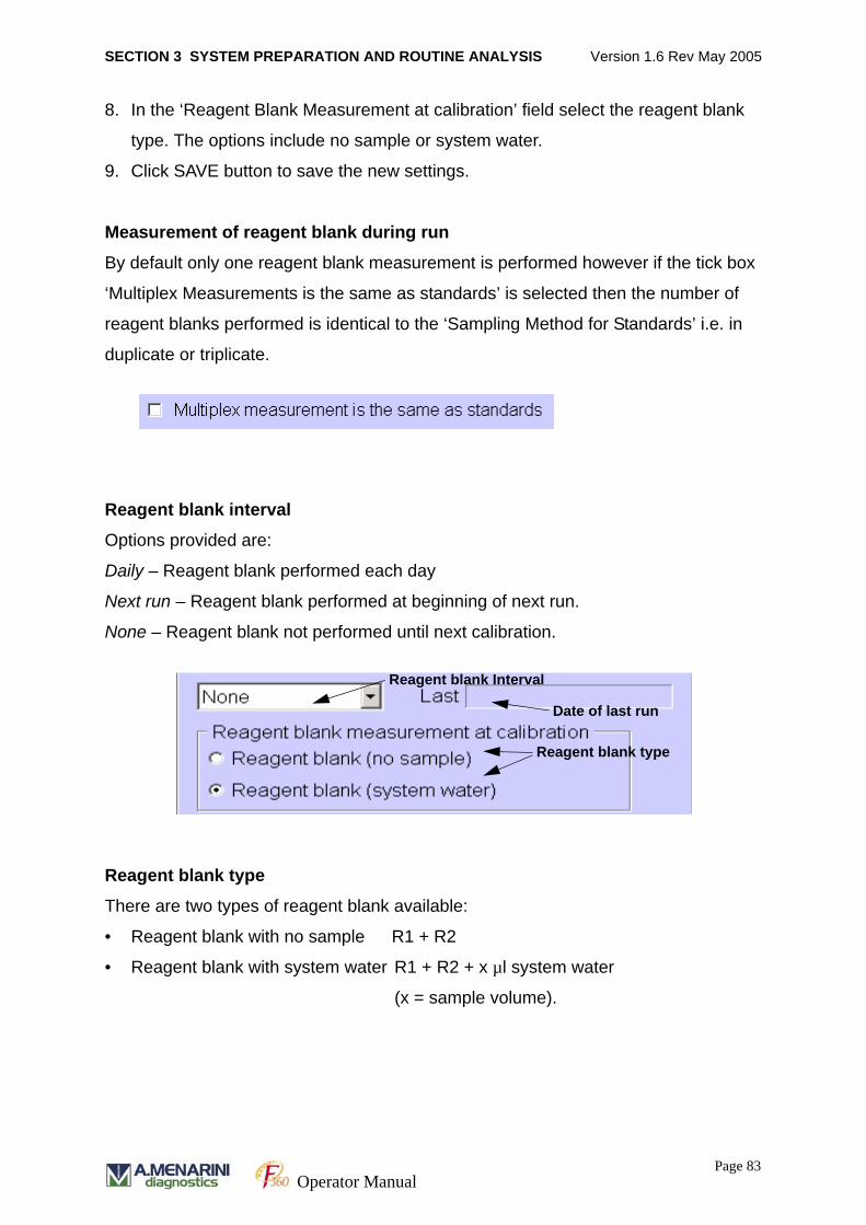
SECTION 3 SYSTEM PREPARATION AND ROUTINE ANALYSIS Version 1.6 Rev May 2005
8. In the ‘Reagent Blank Measurement at calibration’ field select the reagent blank
type. The options include no sample or system water.
9. Click SAVE button to save the new settings.
Measurement of reagent blank during run
By default only one reagent blank measurement is performed however if the tick box
‘Multiplex Measurements is the same as standards’ is selected then the number of
reagent blanks performed is identical to the ‘Sampling Method for Standards’ i.e. in
duplicate or triplicate.
Reagent blank interval
Options provided are:
Daily – Reagent blank performed each day
Next run – Reagent blank performed at beginning of next run.
None – Reagent blank not performed until next calibration.
Reagent blank type
There are two types of reagent blank available:
• Reagent blank with no sample R1 + R2
• Reagent blank with system water R1 + R2 + x µl system water
(x = sample volume).
Reagent blank type
Date of last run
Reagent blank Interval
Page 83Operator Manual
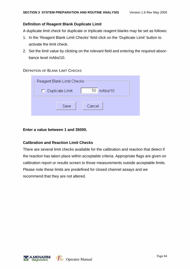
SECTION 3 SYSTEM PREPARATION AND ROUTINE ANALYSIS Version 1.6 Rev May 2005
Definition of Reagent Blank Duplicate Limit
A duplicate limit check for duplicate or triplicate reagent blanks may be set as follows:
1. In the ‘Reagent Blank Limit Checks’ field click on the ‘Duplicate Limit’ button to
activate the limit check.
2. Set the limit value by clicking on the relevant field and entering the required absor-
bance level mAbs/10.
DEFINITION OF BLANK LIMIT CHECKS
Enter a value between 1 and 35000.
Calibration and Reaction Limit Checks
There are several limit checks available for the calibration and reaction that detect if
the reaction has taken place within acceptable criteria. Appropriate flags are given on
calibration report or results screen to those measurements outside acceptable limits.
Please note these limits are predefined for closed channel assays and we
recommend that they are not altered.
Page 84Operator Manual
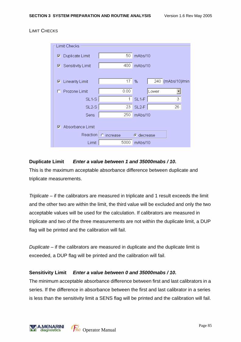
SECTION 3 SYSTEM PREPARATION AND ROUTINE ANALYSIS Version 1.6 Rev May 2005
LIMIT CHECKS
Duplicate Limit Enter a value between 1 and 35000mabs / 10.
This is the maximum acceptable absorbance difference between duplicate and
triplicate measurements.
Triplicate – if the calibrators are measured in triplicate and 1 result exceeds the limit
and the other two are within the limit, the third value will be excluded and only the two
acceptable values will be used for the calculation. If calibrators are measured in
triplicate and two of the three measurements are not within the duplicate limit, a DUP
flag will be printed and the calibration will fail.
Duplicate – if the calibrators are measured in duplicate and the duplicate limit is
exceeded, a DUP flag will be printed and the calibration will fail.
Sensitivity Limit Enter a value between 0 and 35000mabs / 10.
The minimum acceptable absorbance difference between first and last calibrators in a
series. If the difference in absorbance between the first and last calibrator in a series
is less than the sensitivity limit a SENS flag will be printed and the calibration will fail.
Page 85Operator Manual
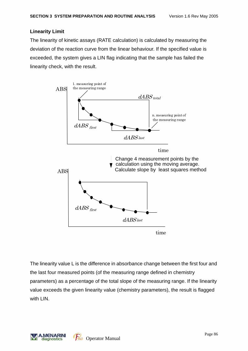
SECTION 3 SYSTEM PREPARATION AND ROUTINE ANALYSIS Version 1.6 Rev May 2005
Linearity Limit
The linearity of kinetic assays (RATE calculation) is calculated by measuring the
deviation of the reaction curve from the linear behaviour. If the specified value is
exceeded, the system gives a LIN flag indicating that the sample has failed the
linearity check, with the result.
The linearity value L is the difference in absorbance change between the first four and
the last four measured points (of the measuring range defined in chemistry
parameters) as a percentage of the total slope of the measuring range. If the linearity
value exceeds the given linearity value (chemistry parameters), the result is flagged
with LIN.
ABS
time
dABS total
dABS last
dABS first
1. measuring point of the measuring range
n. measuring point of the measuring range
ABS
time
dABS last
dABS first
Change 4 measurement points by thecalculation using the moving average. Calculate slope by least squares method
Page 86Operator Manual
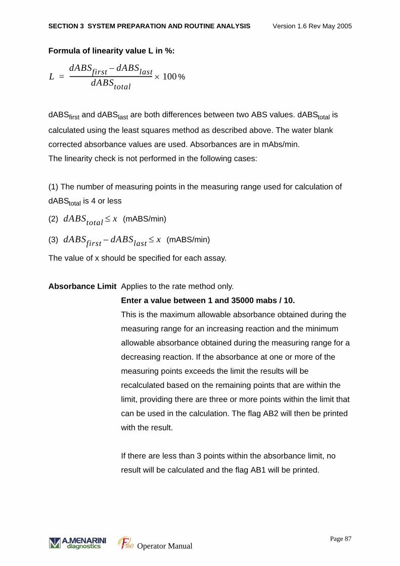
SECTION 3 SYSTEM PREPARATION AND ROUTINE ANALYSIS Version 1.6 Rev May 2005
Formula of linearity value L in %:
%
dABSfirst and dABSlast are both differences between two ABS values. dABStotal is
calculated using the least squares method as described above. The water blank
corrected absorbance values are used. Absorbances are in mAbs/min.
The linearity check is not performed in the following cases:
(1) The number of measuring points in the measuring range used for calculation of
dABStotal is 4 or less
(2) (mABS/min)
(3) (mABS/min)
The value of x should be specified for each assay.
Absorbance Limit Applies to the rate method only.
Enter a value between 1 and 35000 mabs / 10.
This is the maximum allowable absorbance obtained during the
measuring range for an increasing reaction and the minimum
allowable absorbance obtained during the measuring range for a
decreasing reaction. If the absorbance at one or more of the
measuring points exceeds the limit the results will be
recalculated based on the remaining points that are within the
limit, providing there are three or more points within the limit that
can be used in the calculation. The flag AB2 will then be printed
with the result.
If there are less than 3 points within the absorbance limit, no
result will be calculated and the flag AB1 will be printed.
LdABSfirst dABSlast–
dABStotal----------------------------------------------------- 100×=
dABStotal x≤
dABSfirst dABSlast– x≤
Page 87Operator Manual
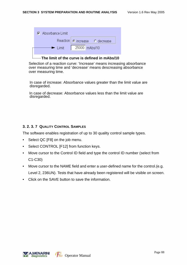
SECTION 3 SYSTEM PREPARATION AND ROUTINE ANALYSIS Version 1.6 Rev May 2005
3. 2. 3. 7 QUALITY CONTROL SAMPLES
The software enables registration of up to 30 quality control sample types.
• Select QC [F8] on the job menu.
• Select CONTROL [F12] from function keys.
• Move cursor to the Control ID field and type the control ID number (select from
C1-C30)
• Move cursor to the NAME field and enter a user-defined name for the control.(e.g.
Level 2, 236UN). Tests that have already been registered will be visible on screen.
• Click on the SAVE button to save the information.
Selection of a reaction curve: ‘Increase’ means increasing absorbanceover measuring time and ‘decrease’ means descreasing absorbance
The limit of the curve is defined in mAbs/10
In case of increase: Absorbance values greater than the limit value are disregarded.
In case of decrease: Absorbance values less than the limit value aredisregarded.
over measuring time.
Page 88Operator Manual
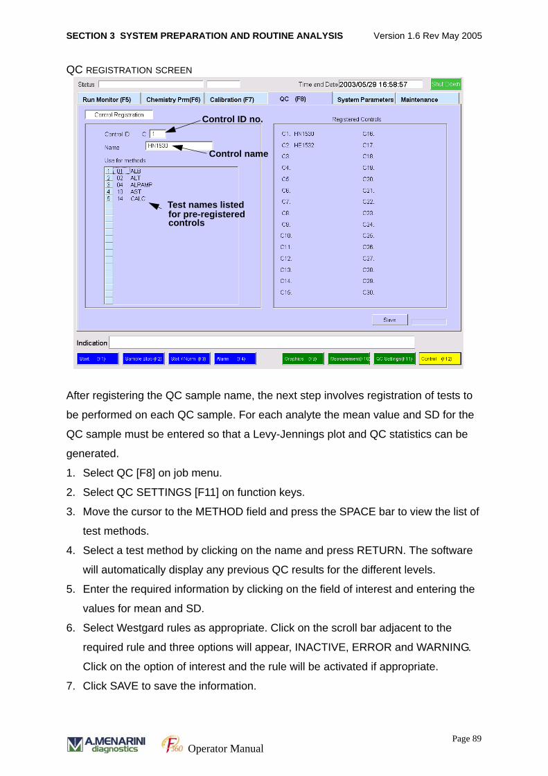
SECTION 3 SYSTEM PREPARATION AND ROUTINE ANALYSIS Version 1.6 Rev May 2005
QC REGISTRATION SCREEN
After registering the QC sample name, the next step involves registration of tests to
be performed on each QC sample. For each analyte the mean value and SD for the
QC sample must be entered so that a Levy-Jennings plot and QC statistics can be
generated.
1. Select QC [F8] on job menu.
2. Select QC SETTINGS [F11] on function keys.
3. Move the cursor to the METHOD field and press the SPACE bar to view the list of
test methods.
4. Select a test method by clicking on the name and press RETURN. The software
will automatically display any previous QC results for the different levels.
5. Enter the required information by clicking on the field of interest and entering the
values for mean and SD.
6. Select Westgard rules as appropriate. Click on the scroll bar adjacent to the
required rule and three options will appear, INACTIVE, ERROR and WARNING.
Click on the option of interest and the rule will be activated if appropriate.
7. Click SAVE to save the information.
Control ID no.
Control name
Test names listedfor pre-registeredcontrols
Page 89Operator Manual
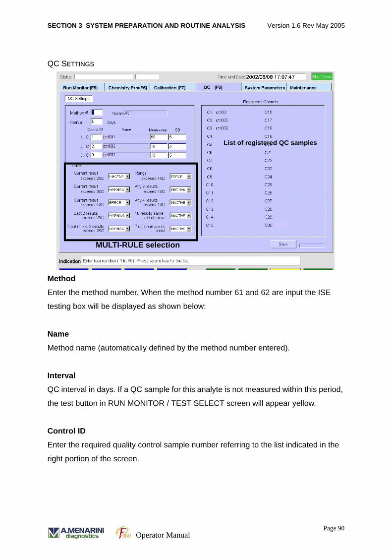
SECTION 3 SYSTEM PREPARATION AND ROUTINE ANALYSIS Version 1.6 Rev May 2005
QC SETTINGS
Method
Enter the method number. When the method number 61 and 62 are input the ISE
testing box will be displayed as shown below:
Name
Method name (automatically defined by the method number entered).
Interval
QC interval in days. If a QC sample for this analyte is not measured within this period,
the test button in RUN MONITOR / TEST SELECT screen will appear yellow.
Control ID
Enter the required quality control sample number referring to the list indicated in the
right portion of the screen.
List of registered QC samples
MULTI-RULE selection
Page 90Operator Manual
SECTION 3 SYSTEM PREPARATION AND ROUTINE ANALYSIS Version 1.6 Rev May 2005
Control Name
Enter the name of quality control sample (automatically defined by the control ID
number entered).
Mean Value
Enter the mean concentration of the specified quality control sample.
SD
Enter the standard deviation of the specified quality control sample. The range of
standard deviation is plotted as dotted lines on the graphic display.
Rules (QC Multi-rules)
The limits of standard deviation are plotted in dotted lines on the graphic display.
QC Multi-rules are used to define the judgment condition of the QC results. The
options are as follows:
Current result exceeds 2SD Current result exceeds 3SD
Current result exceeds 4SD Last 2 results exceed 2SD
2 out of last 3 result exceeds 2SD Range exceeds 4SD
Any 3 results exceed 1SD Any 4 results exceed 1SD
10 results same side of mean 7 continue point trend
For each test there is an option to select any combination of the ten rules displayed
above. Select one of the following - INACTIVE, WARNING, or ERROR.
INACTIVE – The software will default to this option and the adjacent QC Multi-rule will
not be applied.
WARNING – When this option is selected for a given rule the software will display any
QC result that violates the rule as a YELLOW dot on the QC chart. These results will
be included in the overall mean and SD statistics displayed on the QC chart.
Page 91Operator Manual
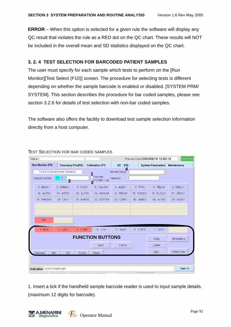
SECTION 3 SYSTEM PREPARATION AND ROUTINE ANALYSIS Version 1.6 Rev May 2005
ERROR – When this option is selected for a given rule the software will display any
QC result that violates the rule as a RED dot on the QC chart. These results will NOT
be included in the overall mean and SD statistics displayed on the QC chart.
3. 2. 4 TEST SELECTION FOR BARCODED PATIENT SAMPLES
The user must specify for each sample which tests to perform on the [Run
Monitor][Test Select (F10)] screen. The procedure for selecting tests is different
depending on whether the sample barcode is enabled or disabled. [SYSTEM PRM/
SYSTEM]. This section describes the procedure for bar coded samples, please see
section 3.2.6 for details of test selection with non-bar coded samples.
The software also offers the facility to download test sample selection information
directly from a host computer.
TEST SELECTION FOR BAR CODED SAMPLES
1. Insert a tick if the handheld sample barcode reader is used to input sample details.
(maximum 12 digits for barcode).
FUNCTION BUTTONS
1
23
4
Page 92Operator Manual
SECTION 3 SYSTEM PREPARATION AND ROUTINE ANALYSIS Version 1.6 Rev May 2005
2. Insert a tick if the sample is a reduced volume paediatric sample. (Maximum 4
digits).
3.Input sample number details (N (normal): 3-12 characters, R (replicate): 2
characters). A replicate barcode must be used for a Replicate sample. See section 3.
2. 5. 4. 3“Information on sample barcode” on page 106.
4. Select which normal range is to be applied to the sample.
[Function buttons]
• Standard: Mask method selection for standard.
• MS: Mask method selection for multi-standard.
• QC: Mask QC method selection
• Profile: Mask the profile items.
• Blank: Mask method selection for blank measurement.
• Save: Save selection.
• Cancel: Cancel selection.
• Copy: Copy test selection.
• Delete: Delete test selection from list.
• List: List stored test selection
• Emergency: Change to Emergency test selection screen
• Online order: Request the test selection data from host when "On Line
Batch1" or "On Line Batch2" mode is enabled in the
[Condition (F12)] [Run Monitor (F5)] screen.
3. 2. 4. 1 NORMAL / REPLICATE SAMPLE TEST SELECTION
Normal patient samples and replicate samples are selected by entering the relevant
barcode number and then confirming tests to be performed. Number of replicates
must be defined in the SYSTEM PRM / SYSTEM / PAGE2 screen.
Manual test selection procedure
1. Select RUN MONITOR [F5] from the job menu.
2. Select TEST SELECT [F10] from the function key menu.
3. Ensure that the page number is page 1 / 2. (Change the page number by clicking
on the page number button).
Page 93Operator Manual
SECTION 3 SYSTEM PREPARATION AND ROUTINE ANALYSIS Version 1.6 Rev May 2005
4. Move the cursor to the ‘SAMPLE NUMBER’ field and click on either ‘N’ (Normal
sample) or ‘R’ (Replicate sample). Replicate sample is selected if the sample
measurement is repeated. A replicate barcode must be used for replicate
samples.
5. Click on and select the BARCODE option box to enter the barcode details via a
barcode reader.
6. Click on and select the PEDIATRIC CUP box for analysis of a pediatric sample
(low volume).
7. Enter the sample number exactly as printed on the barcode label. For a Normal
sample a 3 to 12 digit numerical code from 001 to 999999999999 is acceptable.
Do not use codes from 94000001 to 99999999 for patient samples.
8. For Replicate samples enter a sample number from 01 – 99 as shown on the bar-
code label. [For a replicate sample enter the number of repetitions from 01 to 40
(maximum of 40 times) in the [SYSTEM PRM][SYSTEM(F9)] (PAGE 2 / 2)
9. Enter a PATIENT ID if required (3 to 12 alphanumeric characters).
10.A dialog box will appear on screen prompting the user to ‘Enter sample informa-
tion data’. Click on OK if full patient demographic details are required or CANCEL
if the patient details are not required. For more information on this patient informa-
tion facility see section 4.4.9.4.
11. Click on the Normal range field to specify the range required. To use the standard
normal range values select a blank field. To specify an extension normal range
click on the arrow and select the item of choice. The extension normal ranges may
be set in [CHEMISTRY PRM / CHEMISTRY].
12.Select the tests to be performed by moving the cursor and clicking on the reagent
code button displayed on screen. The selected tests will become highlighted in
bright blue on the screen. Method codes are displayed on screen for reagents
present in the RCU only.
Please note that methods utilising a diluent will NOT appear for selection
unless the diluent is registered on board the analyser.
ISE measurements and test profiles are selected in the same way. Multiple
method selection can be made for each sample.
Page 94Operator Manual

SECTION 3 SYSTEM PREPARATION AND ROUTINE ANALYSIS Version 1.6 Rev May 2005
Methods are flagged with different colours to warn the user as follows:
RED colour (general methods) Calibration has expired
RED colour (ISE) No valid ISE calibration stored
YELLOW colour QC interval has been exceeded
13.Click on the SAVE icon to confirm selection. The Sample Number field will auto-
matically increment by one in preparation for the next sample entry.
3. 2. 4. 2 COPYING TEST SELECTIONS FOR BARCODED SAMPLES
When a number of samples are presented for the same test profile, the test sample
selection details may be applied to the samples using the COPY facility. The first
sample must already have had a test sample selected and saved before the copy
facility is used. After entry of a test menu for a sample follow the instructions below.
Copying test selection to other samples
Copying test selection for Normal sample
1. Click on the COPY option as shown on the screen above.
2. In the COPY FROM SAMPLE NUMBER field enter the sample number (minimum
3 digits) for which the test selection has already been made.
3. In the COPY TO SAMPLE NUMBERS field enter the sample numbers (minimum 3
digits) FROM and TO, to which the same test selection is applied.
Page 95Operator Manual
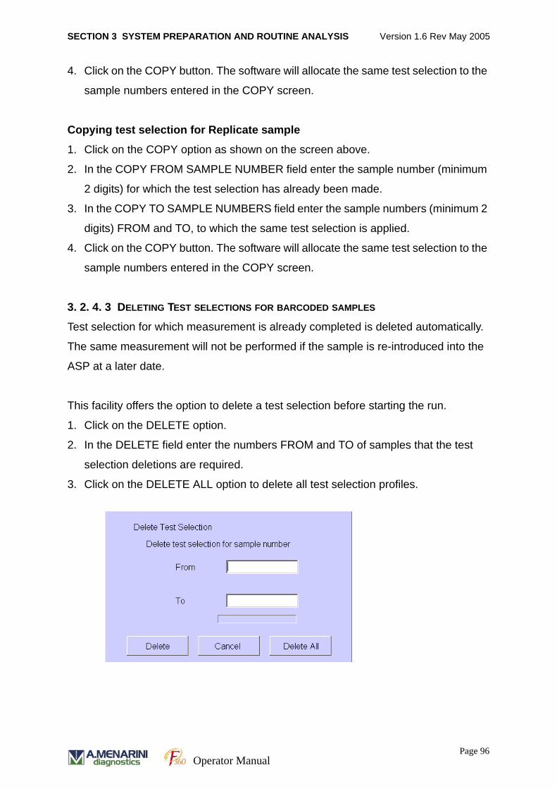
SECTION 3 SYSTEM PREPARATION AND ROUTINE ANALYSIS Version 1.6 Rev May 2005
4. Click on the COPY button. The software will allocate the same test selection to the
sample numbers entered in the COPY screen.
Copying test selection for Replicate sample
1. Click on the COPY option as shown on the screen above.
2. In the COPY FROM SAMPLE NUMBER field enter the sample number (minimum
2 digits) for which the test selection has already been made.
3. In the COPY TO SAMPLE NUMBERS field enter the sample numbers (minimum 2
digits) FROM and TO, to which the same test selection is applied.
4. Click on the COPY button. The software will allocate the same test selection to the
sample numbers entered in the COPY screen.
3. 2. 4. 3 DELETING TEST SELECTIONS FOR BARCODED SAMPLES
Test selection for which measurement is already completed is deleted automatically.
The same measurement will not be performed if the sample is re-introduced into the
ASP at a later date.
This facility offers the option to delete a test selection before starting the run.
1. Click on the DELETE option.
2. In the DELETE field enter the numbers FROM and TO of samples that the test
selection deletions are required.
3. Click on the DELETE ALL option to delete all test selection profiles.
Page 96Operator Manual
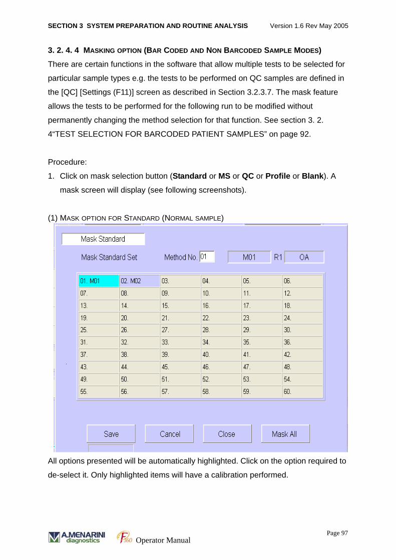
SECTION 3 SYSTEM PREPARATION AND ROUTINE ANALYSIS Version 1.6 Rev May 2005
3. 2. 4. 4 MASKING OPTION (BAR CODED AND NON BARCODED SAMPLE MODES)
There are certain functions in the software that allow multiple tests to be selected for
particular sample types e.g. the tests to be performed on QC samples are defined in
the [QC] [Settings (F11)] screen as described in Section 3.2.3.7. The mask feature
allows the tests to be performed for the following run to be modified without
permanently changing the method selection for that function. See section 3. 2.
4“TEST SELECTION FOR BARCODED PATIENT SAMPLES” on page 92.
Procedure:
1. Click on mask selection button (Standard or MS or QC or Profile or Blank). A
mask screen will display (see following screenshots).
(1) MASK OPTION FOR STANDARD (NORMAL SAMPLE)
All options presented will be automatically highlighted. Click on the option required to
de-select it. Only highlighted items will have a calibration performed.
Page 97Operator Manual
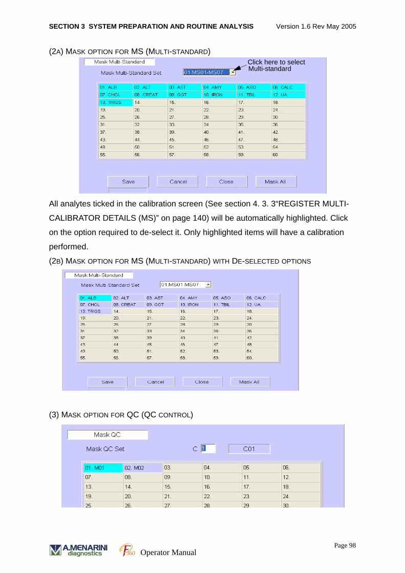
SECTION 3 SYSTEM PREPARATION AND ROUTINE ANALYSIS Version 1.6 Rev May 2005
(2A) MASK OPTION FOR MS (MULTI-STANDARD)
All analytes ticked in the calibration screen (See section 4. 3. 3“REGISTER MULTI-
CALIBRATOR DETAILS (MS)” on page 140) will be automatically highlighted. Click
on the option required to de-select it. Only highlighted items will have a calibration
performed.
(2B) MASK OPTION FOR MS (MULTI-STANDARD) WITH DE-SELECTED OPTIONS
(3) MASK OPTION FOR QC (QC CONTROL)
Click here to selectMulti-standard
Page 98Operator Manual
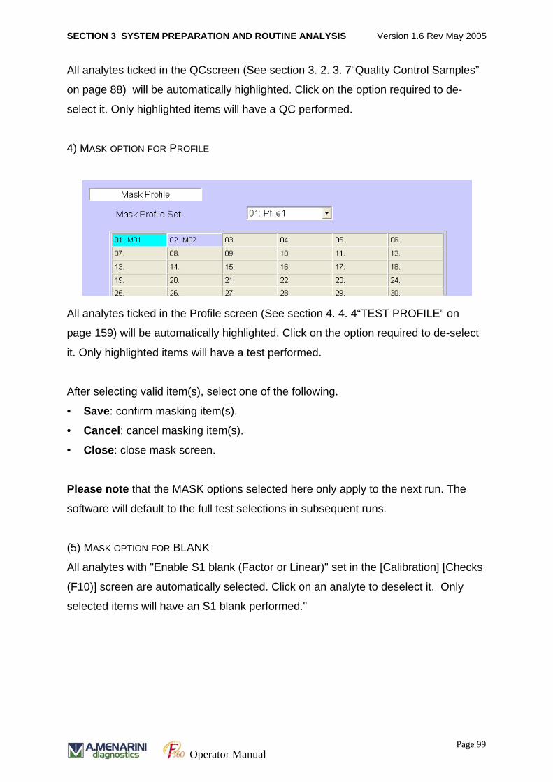
SECTION 3 SYSTEM PREPARATION AND ROUTINE ANALYSIS Version 1.6 Rev May 2005
All analytes ticked in the QCscreen (See section 3. 2. 3. 7“Quality Control Samples”
on page 88) will be automatically highlighted. Click on the option required to de-
select it. Only highlighted items will have a QC performed.
4) MASK OPTION FOR PROFILE
All analytes ticked in the Profile screen (See section 4. 4. 4“TEST PROFILE” on
page 159) will be automatically highlighted. Click on the option required to de-select
it. Only highlighted items will have a test performed.
After selecting valid item(s), select one of the following.
• Save: confirm masking item(s).
• Cancel: cancel masking item(s).
• Close: close mask screen.
Please note that the MASK options selected here only apply to the next run. The
software will default to the full test selections in subsequent runs.
(5) MASK OPTION FOR BLANK
All analytes with "Enable S1 blank (Factor or Linear)" set in the [Calibration] [Checks
(F10)] screen are automatically selected. Click on an analyte to deselect it. Only
selected items will have an S1 blank performed."
Page 99Operator Manual
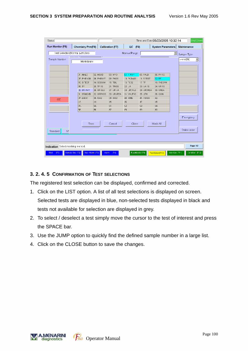
SECTION 3 SYSTEM PREPARATION AND ROUTINE ANALYSIS Version 1.6 Rev May 2005
3. 2. 4. 5 CONFIRMATION OF TEST SELECTIONS
The registered test selection can be displayed, confirmed and corrected.
1. Click on the LIST option. A list of all test selections is displayed on screen.
Selected tests are displayed in blue, non-selected tests displayed in black and
tests not available for selection are displayed in grey.
2. To select / deselect a test simply move the cursor to the test of interest and press
the SPACE bar.
3. Use the JUMP option to quickly find the defined sample number in a large list.
4. Click on the CLOSE button to save the changes.
Page 100Operator Manual
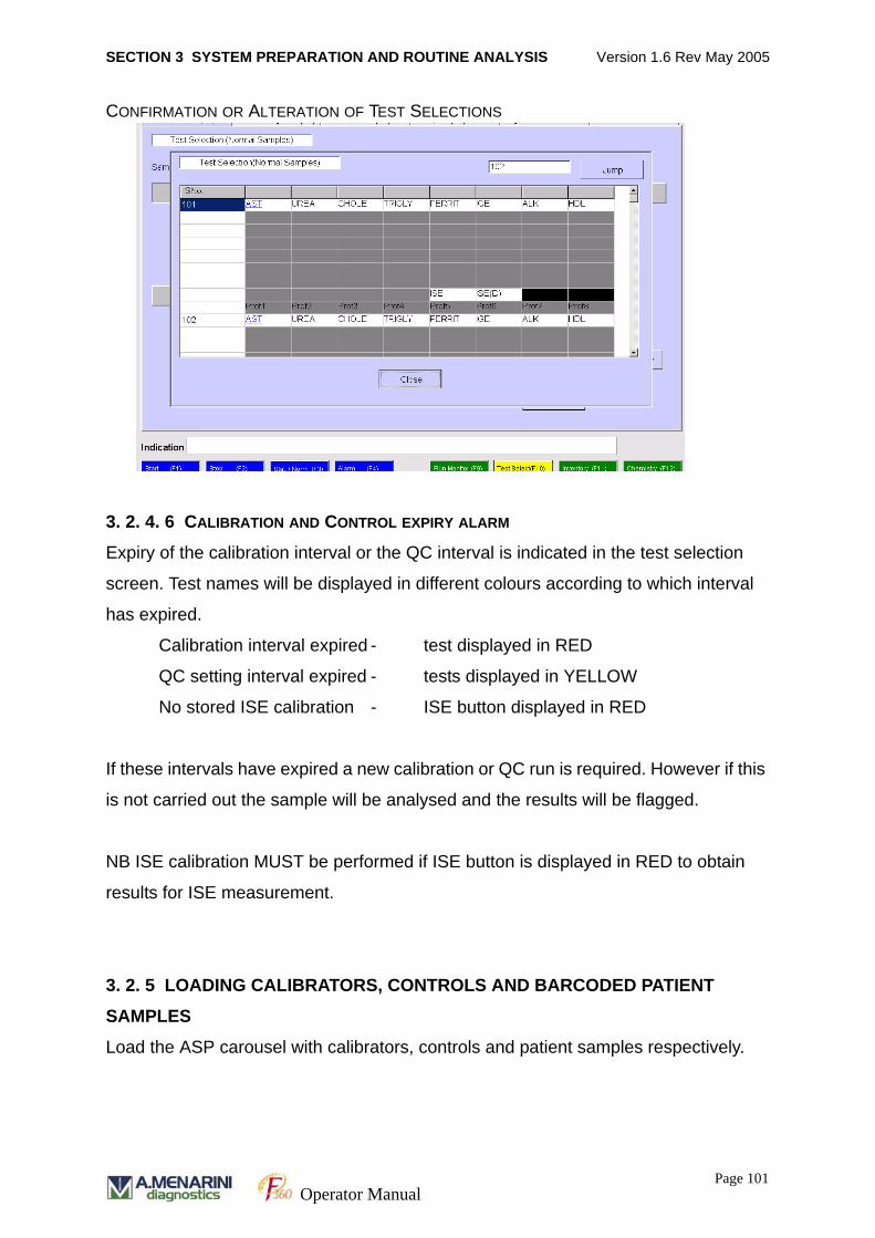
SECTION 3 SYSTEM PREPARATION AND ROUTINE ANALYSIS Version 1.6 Rev May 2005
CONFIRMATION OR ALTERATION OF TEST SELECTIONS
3. 2. 4. 6 CALIBRATION AND CONTROL EXPIRY ALARM
Expiry of the calibration interval or the QC interval is indicated in the test selection
screen. Test names will be displayed in different colours according to which interval
has expired.
Calibration interval expired - test displayed in RED
QC setting interval expired - tests displayed in YELLOW
No stored ISE calibration - ISE button displayed in RED
If these intervals have expired a new calibration or QC run is required. However if this
is not carried out the sample will be analysed and the results will be flagged.
NB ISE calibration MUST be performed if ISE button is displayed in RED to obtain
results for ISE measurement.
3. 2. 5 LOADING CALIBRATORS, CONTROLS AND BARCODED PATIENT
SAMPLES
Load the ASP carousel with calibrators, controls and patient samples respectively.
Page 101Operator Manual

SECTION 3 SYSTEM PREPARATION AND ROUTINE ANALYSIS Version 1.6 Rev May 2005
The ASP rotates in a counter clockwise direction and samples are aspirated in the
order in which they reach the SPT position. Place samples according to the following
guidelines:
• Place calibrators in front of patient samples.
• Calibrators in a series should be placed in any order of concentration.
• Quality Control samples can be placed in any position but ideally should be placed
after the calibrators.
• CAL B or wash solution should be placed at position 18 on the ASP, when appro-
priate.
All samples are identified by barcodes. Sample tubes should be placed in the rack
with the barcode presented appropriately for barcode reader detection.
The device can accommodate total 40 samples (normal, emergency, quality control,
standard) in sample cups or sample tubes.
3. 2. 5. 1 SAMPLE TUBES
The following sample tubes can be used.
Diameter: 13 mm ~ 16 mm
Length: 75 mm ~ 100 mm
Ensure that barcode labels are applied correctly to the sample tubes. This enables
the barcode reader to identify the sample. (See Accessory functions section).
3. 2. 5. 2 SAMPLE CUPS
Sarstedt Tube - Cat No. 55.472 - Tube 6.5ml 85 x 13mm PS
Sample cups may be used in the analyser by placing them in a bar coded patient
sample tube as shown. The sample tube with cup can be loaded into the ASP
carousel and identified by the barcode on the sample tube.
Page 102Operator Manual
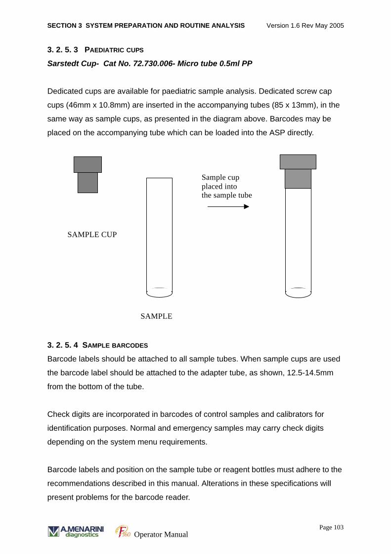
SECTION 3 SYSTEM PREPARATION AND ROUTINE ANALYSIS Version 1.6 Rev May 2005
3. 2. 5. 3 PAEDIATRIC CUPS
Sarstedt Cup- Cat No. 72.730.006- Micro tube 0.5ml PP
Dedicated cups are available for paediatric sample analysis. Dedicated screw cap
cups (46mm x 10.8mm) are inserted in the accompanying tubes (85 x 13mm), in the
same way as sample cups, as presented in the diagram above. Barcodes may be
placed on the accompanying tube which can be loaded into the ASP directly.
3. 2. 5. 4 SAMPLE BARCODES
Barcode labels should be attached to all sample tubes. When sample cups are used
the barcode label should be attached to the adapter tube, as shown, 12.5-14.5mm
from the bottom of the tube.
Check digits are incorporated in barcodes of control samples and calibrators for
identification purposes. Normal and emergency samples may carry check digits
depending on the system menu requirements.
Barcode labels and position on the sample tube or reagent bottles must adhere to the
recommendations described in this manual. Alterations in these specifications will
present problems for the barcode reader.
SAMPLE CUP
SAMPLE
Sample cup placed into the sample tube
Page 103Operator Manual
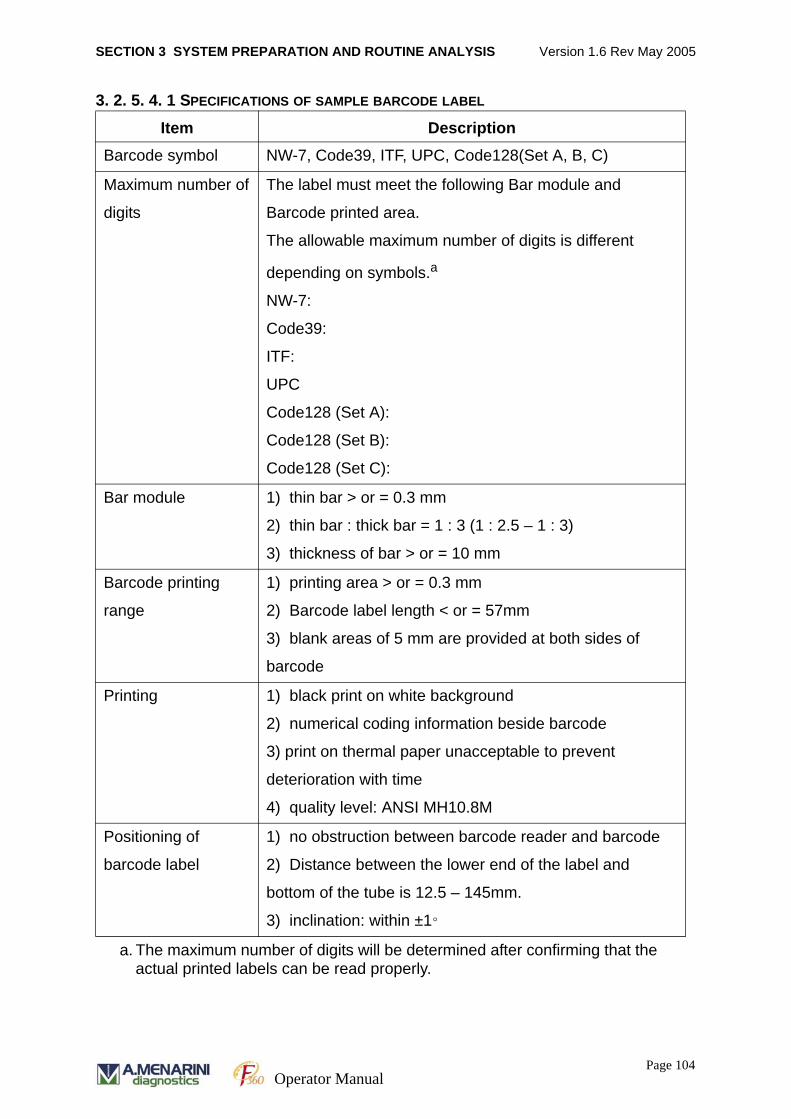
SECTION 3 SYSTEM PREPARATION AND ROUTINE ANALYSIS Version 1.6 Rev May 2005
3. 2. 5. 4. 1 SPECIFICATIONS OF SAMPLE BARCODE LABEL
Item DescriptionBarcode symbol NW-7, Code39, ITF, UPC, Code128(Set A, B, C)
Maximum number of
digits
The label must meet the following Bar module and
Barcode printed area.
The allowable maximum number of digits is different
depending on symbols.a
NW-7:
Code39:
ITF:
UPC
Code128 (Set A):
Code128 (Set B):
Code128 (Set C):
a. The maximum number of digits will be determined after confirming that the actual printed labels can be read properly.
Bar module 1) thin bar > or = 0.3 mm
2) thin bar : thick bar = 1 : 3 (1 : 2.5 – 1 : 3)
3) thickness of bar > or = 10 mm
Barcode printing
range
1) printing area > or = 0.3 mm
2) Barcode label length < or = 57mm
3) blank areas of 5 mm are provided at both sides of
barcode
Printing 1) black print on white background
2) numerical coding information beside barcode
3) print on thermal paper unacceptable to prevent
deterioration with time
4) quality level: ANSI MH10.8M
Positioning of
barcode label
1) no obstruction between barcode reader and barcode
2) Distance between the lower end of the label and
bottom of the tube is 12.5 – 145mm.
3) inclination: within ±1°
Page 104Operator Manual
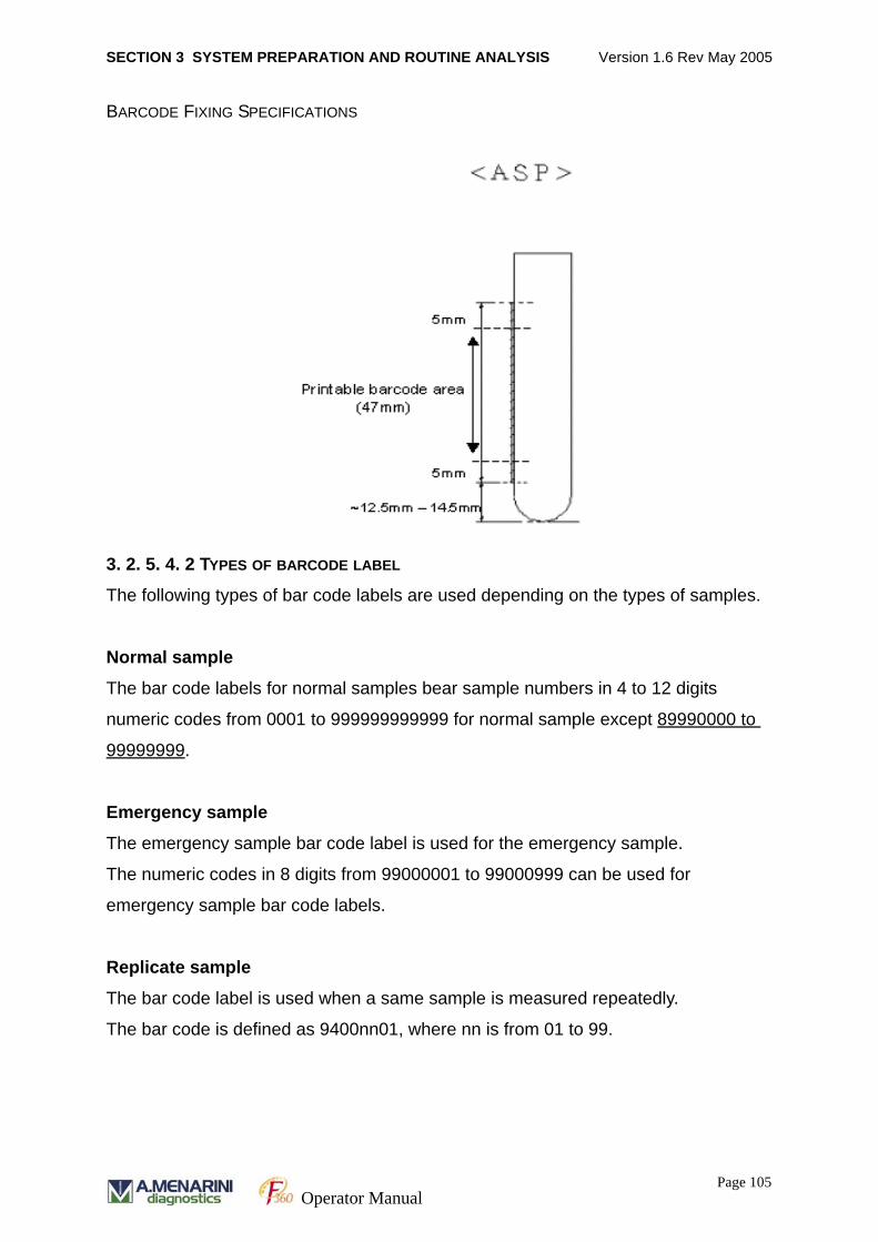
SECTION 3 SYSTEM PREPARATION AND ROUTINE ANALYSIS Version 1.6 Rev May 2005
BARCODE FIXING SPECIFICATIONS
3. 2. 5. 4. 2 TYPES OF BARCODE LABEL
The following types of bar code labels are used depending on the types of samples.
Normal sample
The bar code labels for normal samples bear sample numbers in 4 to 12 digits
numeric codes from 0001 to 999999999999 for normal sample except 89990000 to
99999999.
Emergency sample
The emergency sample bar code label is used for the emergency sample.
The numeric codes in 8 digits from 99000001 to 99000999 can be used for
emergency sample bar code labels.
Replicate sample
The bar code label is used when a same sample is measured repeatedly.
The bar code is defined as 9400nn01, where nn is from 01 to 99.
Page 105Operator Manual
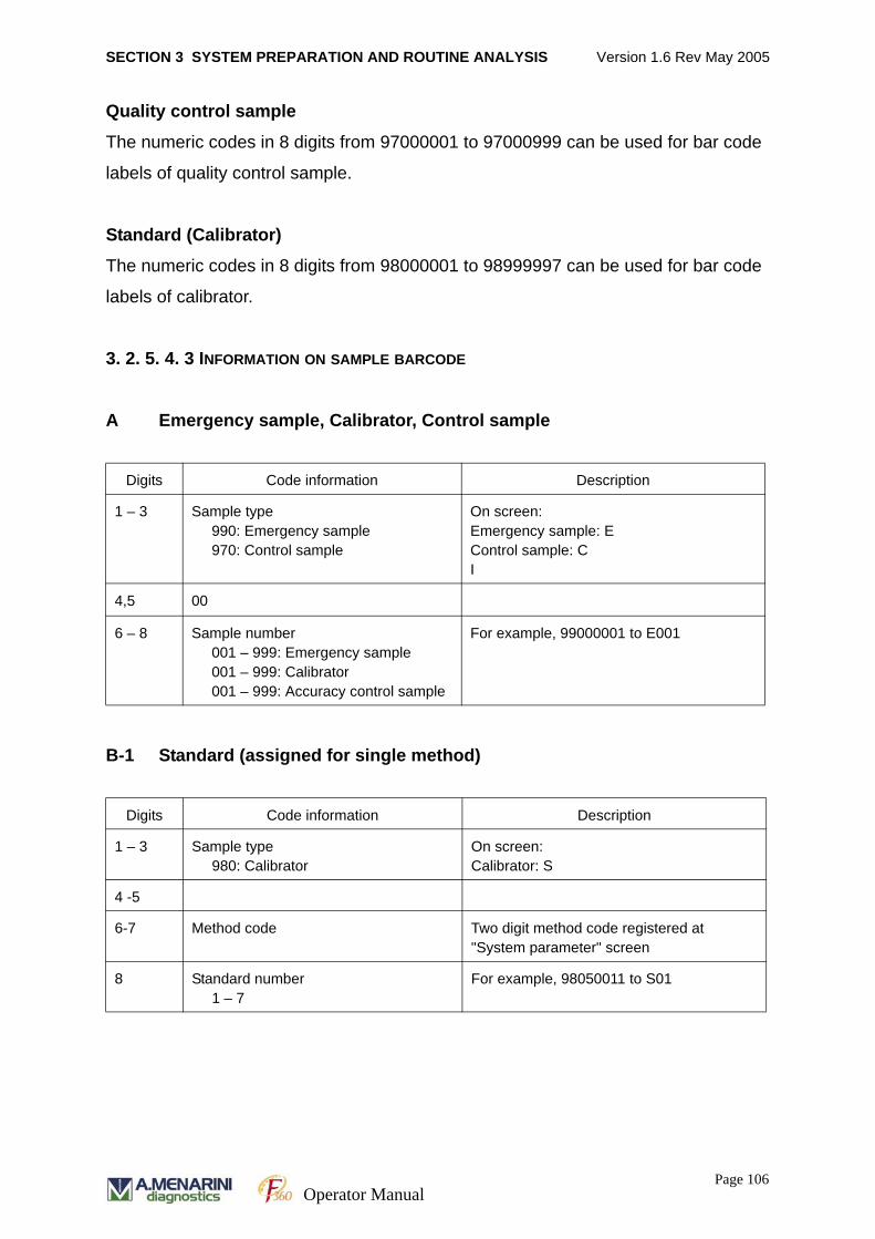
SECTION 3 SYSTEM PREPARATION AND ROUTINE ANALYSIS Version 1.6 Rev May 2005
Quality control sample
The numeric codes in 8 digits from 97000001 to 97000999 can be used for bar code
labels of quality control sample.
Standard (Calibrator)
The numeric codes in 8 digits from 98000001 to 98999997 can be used for bar code
labels of calibrator.
3. 2. 5. 4. 3 INFORMATION ON SAMPLE BARCODE
A Emergency sample, Calibrator, Control sample
B-1 Standard (assigned for single method)
Digits Code information Description
1 – 3 Sample type990: Emergency sample970: Control sample
On screen:Emergency sample: EControl sample: CI
4,5 00
6 – 8 Sample number001 – 999: Emergency sample001 – 999: Calibrator001 – 999: Accuracy control sample
For example, 99000001 to E001
Digits Code information Description
1 – 3 Sample type980: Calibrator
On screen:Calibrator: S
4 -5
6-7 Method code Two digit method code registered at "System parameter" screen
8 Standard number1 – 7
For example, 98050011 to S01
Page 106Operator Manual
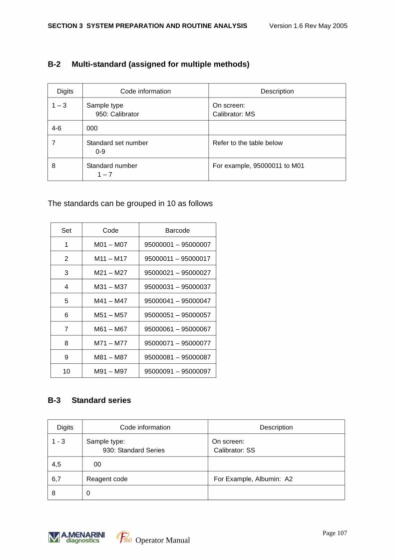
SECTION 3 SYSTEM PREPARATION AND ROUTINE ANALYSIS Version 1.6 Rev May 2005
B-2 Multi-standard (assigned for multiple methods)
The standards can be grouped in 10 as follows
B-3 Standard series
Digits Code information Description
1 – 3 Sample type950: Calibrator
On screen:Calibrator: MS
4-6 000
7 Standard set number0-9
Refer to the table below
8 Standard number1 – 7
For example, 95000011 to M01
Set Code Barcode
1 M01 – M07 95000001 – 95000007
2 M11 – M17 95000011 – 95000017
3 M21 – M27 95000021 – 95000027
4 M31 – M37 95000031 – 95000037
5 M41 – M47 95000041 – 95000047
6 M51 – M57 95000051 – 95000057
7 M61 – M67 95000061 – 95000067
8 M71 – M77 95000071 – 95000077
9 M81 – M87 95000081 – 95000087
10 M91 – M97 95000091 – 95000097
Digits Code information Description
1 - 3 Sample type: 930: Standard Series
On screen: Calibrator: SS
4,5 00
6,7 Reagent code For Example, Albumin: A2
8 0
Page 107Operator Manual
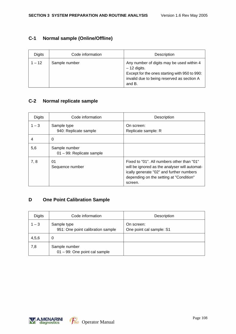
SECTION 3 SYSTEM PREPARATION AND ROUTINE ANALYSIS Version 1.6 Rev May 2005
C-1 Normal sample (Online/Offline)
C-2 Normal replicate sample
D One Point Calibration Sample
Digits Code information Description
1 – 12 Sample number Any number of digits may be used within 4 – 12 digits.Except for the ones starting with 950 to 990: invalid due to being reserved as section A and B.
Digits Code information Description
1 – 3 Sample type940: Replicate sample
On screen:Replicate sample: R
4 0
5,6 Sample number01 – 99: Replicate sample
7, 8 01Sequence number
Fixed to "01". All numbers other than "01" will be ignored as the analyser will automat-ically generate "02" and further numbers depending on the setting at "Condition" screen.
Digits Code information Description
1 – 3 Sample type951: One point calibration sample
On screen:One point cal sample: S1
4,5,6 0
7,8 Sample number01 – 99: One point cal sample
Page 108Operator Manual
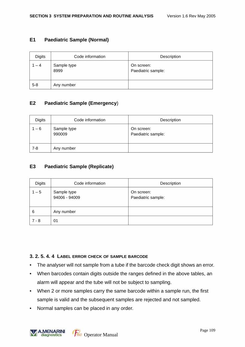
SECTION 3 SYSTEM PREPARATION AND ROUTINE ANALYSIS Version 1.6 Rev May 2005
E1 Paediatric Sample (Normal)
E2 Paediatric Sample (Emergency)
E3 Paediatric Sample (Replicate)
3. 2. 5. 4. 4 LABEL ERROR CHECK OF SAMPLE BARCODE
• The analyser will not sample from a tube if the barcode check digit shows an error.
• When barcodes contain digits outside the ranges defined in the above tables, an
alarm will appear and the tube will not be subject to sampling.
• When 2 or more samples carry the same barcode within a sample run, the first
sample is valid and the subsequent samples are rejected and not sampled.
• Normal samples can be placed in any order.
Digits Code information Description
1 – 4 Sample type8999
On screen:Paediatric sample:
5-8 Any number
Digits Code information Description
1 – 6 Sample type990009
On screen:Paediatric sample:
7-8 Any number
Digits Code information Description
1 – 5 Sample type94006 - 94009
On screen:Paediatric sample:
6 Any number
7 - 8 01
Page 109Operator Manual
SECTION 3 SYSTEM PREPARATION AND ROUTINE ANALYSIS Version 1.6 Rev May 2005
3. 2. 6 TEST SELECTION FOR NON-BARCODED PATIENT SAMPLES
Information on sample type and tests required can be entered manually for non-bar
coded samples, or received from a host.
Note: The barcode option MUST be disabled when non bar coded samples are run.
To disable the barcode option go to SYSTEM PARAMETERS/ SYSTEM (F9) and go
to SAMPLE BARCODE. Click on the DISABLE option and then click OK on the pop
up screen.
The following instructions must be followed to input information for non-barcoded
samples.
1. Select RUN MONITOR [F5] from the job menu.
2. Select TEST SELECT [F10] from the function key menu.
3. Click on the desired sample position number on the left side of the screen. The
selected position will be highlighted in blue.
4. Click on the required sample TYPE.
E –Emergency sample
N – normal sample (single run)
S – single standard (calibrator)
MS – Multi standard,
SS – Standard series
B – Blank sample
C – control sample
R – replicate sample
5. The sample number will be automatically displayed. Enter a different sample num-
ber if desired (3 to 12 digits except 90000000 to 99999999) in the ‘Sample Num-
ber’ field. Click on the patient ID field and enter the ID number if required.
6. A dialog box will appear on screen prompting the user to ‘Enter sample informa-
tion data’. Click on OK if you wish to enter full patient demographic information or
CANCEL if this option is not required. (See section 4.4.9.4 on the use of patient
information).
Page 110Operator Manual
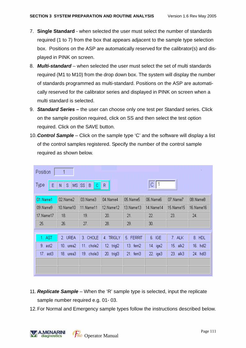
SECTION 3 SYSTEM PREPARATION AND ROUTINE ANALYSIS Version 1.6 Rev May 2005
7. Single Standard - when selected the user must select the number of standards
required (1 to 7) from the box that appears adjacent to the sample type selection
box. Positions on the ASP are automatically reserved for the calibrator(s) and dis-
played in PINK on screen.
8. Multi-standard – when selected the user must select the set of multi standards
required (M1 to M10) from the drop down box. The system will display the number
of standards programmed as multi-standard. Positions on the ASP are automati-
cally reserved for the calibrator series and displayed in PINK on screen when a
multi standard is selected.
9. Standard Series – the user can choose only one test per Standard series. Click
on the sample position required, click on SS and then select the test option
required. Click on the SAVE button.
10.Control Sample – Click on the sample type ‘C’ and the software will display a list
of the control samples registered. Specify the number of the control sample
required as shown below.
11. Replicate Sample – When the ‘R’ sample type is selected, input the replicate
sample number required e.g. 01- 03.
12.For Normal and Emergency sample types follow the instructions described below.
Page 111Operator Manual
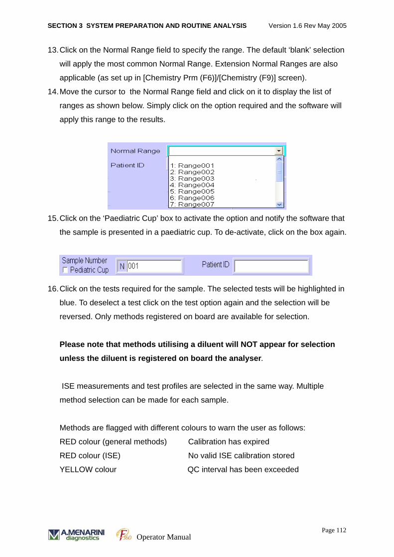
SECTION 3 SYSTEM PREPARATION AND ROUTINE ANALYSIS Version 1.6 Rev May 2005
13.Click on the Normal Range field to specify the range. The default ‘blank’ selection
will apply the most common Normal Range. Extension Normal Ranges are also
applicable (as set up in [Chemistry Prm (F6)]/[Chemistry (F9)] screen).
14.Move the cursor to the Normal Range field and click on it to display the list of
ranges as shown below. Simply click on the option required and the software will
apply this range to the results.
15.Click on the ‘Paediatric Cup’ box to activate the option and notify the software that
the sample is presented in a paediatric cup. To de-activate, click on the box again.
16.Click on the tests required for the sample. The selected tests will be highlighted in
blue. To deselect a test click on the test option again and the selection will be
reversed. Only methods registered on board are available for selection.
Please note that methods utilising a diluent will NOT appear for selection
unless the diluent is registered on board the analyser.
ISE measurements and test profiles are selected in the same way. Multiple
method selection can be made for each sample.
Methods are flagged with different colours to warn the user as follows:
RED colour (general methods) Calibration has expired
RED colour (ISE) No valid ISE calibration stored
YELLOW colour QC interval has been exceeded
Page 112Operator Manual
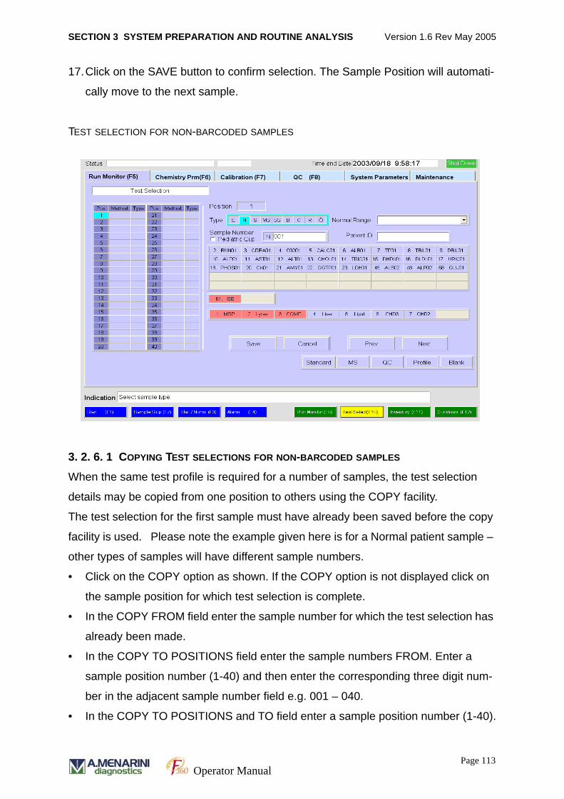
SECTION 3 SYSTEM PREPARATION AND ROUTINE ANALYSIS Version 1.6 Rev May 2005
17.Click on the SAVE button to confirm selection. The Sample Position will automati-
cally move to the next sample.
TEST SELECTION FOR NON-BARCODED SAMPLES
3. 2. 6. 1 COPYING TEST SELECTIONS FOR NON-BARCODED SAMPLES
When the same test profile is required for a number of samples, the test selection
details may be copied from one position to others using the COPY facility.
The test selection for the first sample must have already been saved before the copy
facility is used. Please note the example given here is for a Normal patient sample –
other types of samples will have different sample numbers.
• Click on the COPY option as shown. If the COPY option is not displayed click on
the sample position for which test selection is complete.
• In the COPY FROM field enter the sample number for which the test selection has
already been made.
• In the COPY TO POSITIONS field enter the sample numbers FROM. Enter a
sample position number (1-40) and then enter the corresponding three digit num-
ber in the adjacent sample number field e.g. 001 – 040.
• In the COPY TO POSITIONS and TO field enter a sample position number (1-40).
Page 113Operator Manual
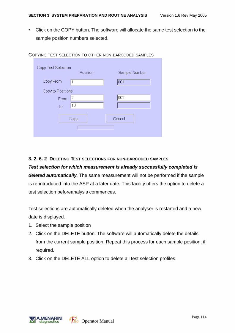
SECTION 3 SYSTEM PREPARATION AND ROUTINE ANALYSIS Version 1.6 Rev May 2005
• Click on the COPY button. The software will allocate the same test selection to the
sample position numbers selected.
COPYING TEST SELECTION TO OTHER NON-BARCODED SAMPLES
3. 2. 6. 2 DELETING TEST SELECTIONS FOR NON-BARCODED SAMPLES
Test selection for which measurement is already successfully completed is
deleted automatically. The same measurement will not be performed if the sample
is re-introduced into the ASP at a later date. This facility offers the option to delete a
test selection beforeanalysis commences.
Test selections are automatically deleted when the analyser is restarted and a new
date is displayed.
1. Select the sample position
2. Click on the DELETE button. The software will automatically delete the details
from the current sample position. Repeat this process for each sample position, if
required.
3. Click on the DELETE ALL option to delete all test selection profiles.
Page 114Operator Manual
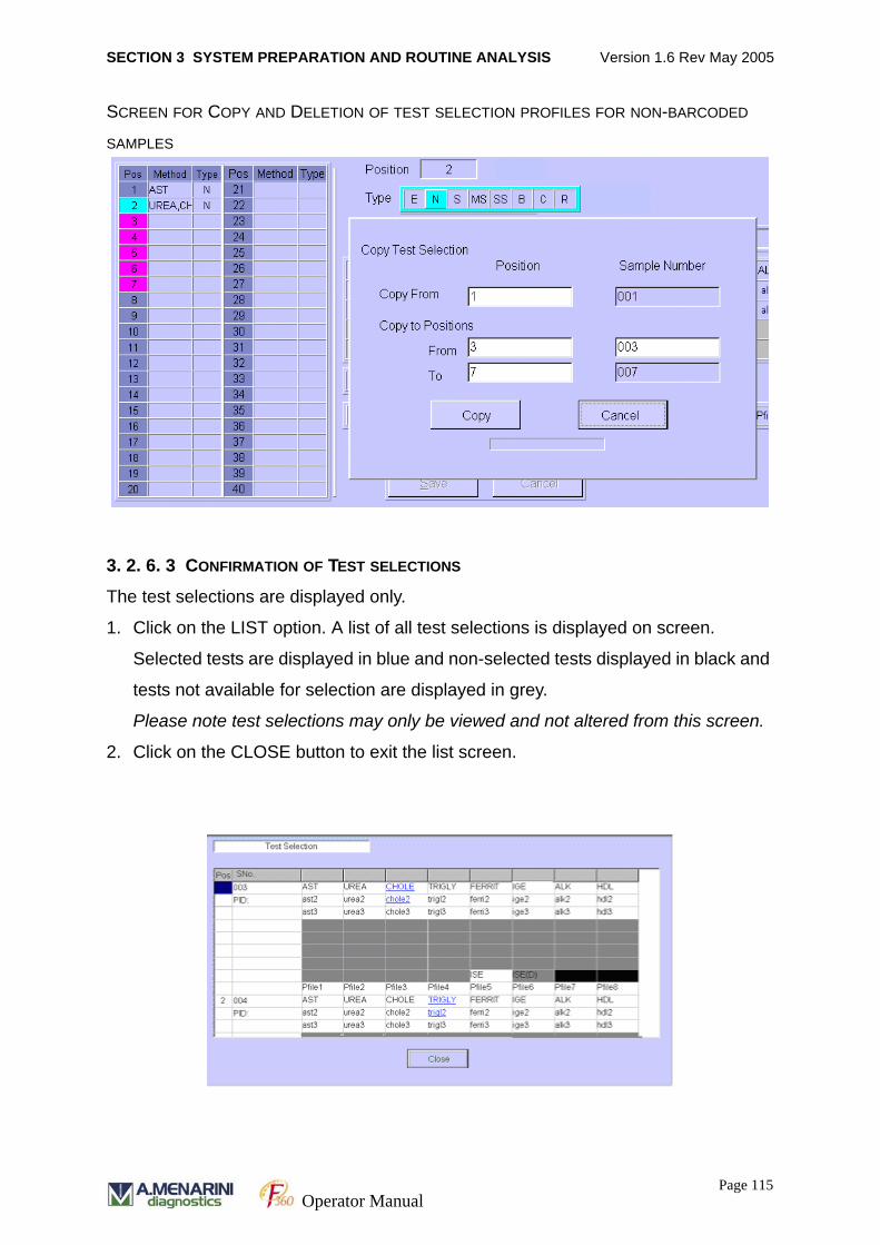
SECTION 3 SYSTEM PREPARATION AND ROUTINE ANALYSIS Version 1.6 Rev May 2005
SCREEN FOR COPY AND DELETION OF TEST SELECTION PROFILES FOR NON-BARCODED
SAMPLES
3. 2. 6. 3 CONFIRMATION OF TEST SELECTIONS
The test selections are displayed only.
1. Click on the LIST option. A list of all test selections is displayed on screen.
Selected tests are displayed in blue and non-selected tests displayed in black and
tests not available for selection are displayed in grey.
Please note test selections may only be viewed and not altered from this screen.
2. Click on the CLOSE button to exit the list screen.
Page 115Operator Manual
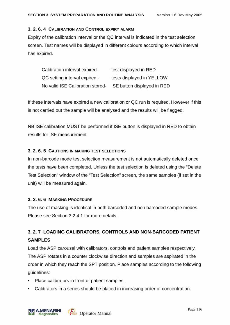
SECTION 3 SYSTEM PREPARATION AND ROUTINE ANALYSIS Version 1.6 Rev May 2005
3. 2. 6. 4 CALIBRATION AND CONTROL EXPIRY ALARM
Expiry of the calibration interval or the QC interval is indicated in the test selection
screen. Test names will be displayed in different colours according to which interval
has expired.
Calibration interval expired - test displayed in RED
QC setting interval expired - tests displayed in YELLOW
No valid ISE Calibration stored- ISE button displayed in RED
If these intervals have expired a new calibration or QC run is required. However if this
is not carried out the sample will be analysed and the results will be flagged.
NB ISE calibration MUST be performed if ISE button is displayed in RED to obtain
results for ISE measurement.
3. 2. 6. 5 CAUTIONS IN MAKING TEST SELECTIONS
In non-barcode mode test selection measurement is not automatically deleted once
the tests have been completed. Unless the test selection is deleted using the “Delete
Test Selection” window of the “Test Selection” screen, the same samples (if set in the
unit) will be measured again.
3. 2. 6. 6 MASKING PROCEDURE
The use of masking is identical in both barcoded and non barcoded sample modes.
Please see Section 3.2.4.1 for more details.
3. 2. 7 LOADING CALIBRATORS, CONTROLS AND NON-BARCODED PATIENT
SAMPLES
Load the ASP carousel with calibrators, controls and patient samples respectively.
The ASP rotates in a counter clockwise direction and samples are aspirated in the
order in which they reach the SPT position. Place samples according to the following
guidelines:
• Place calibrators in front of patient samples.
• Calibrators in a series should be placed in increasing order of concentration.
Page 116Operator Manual
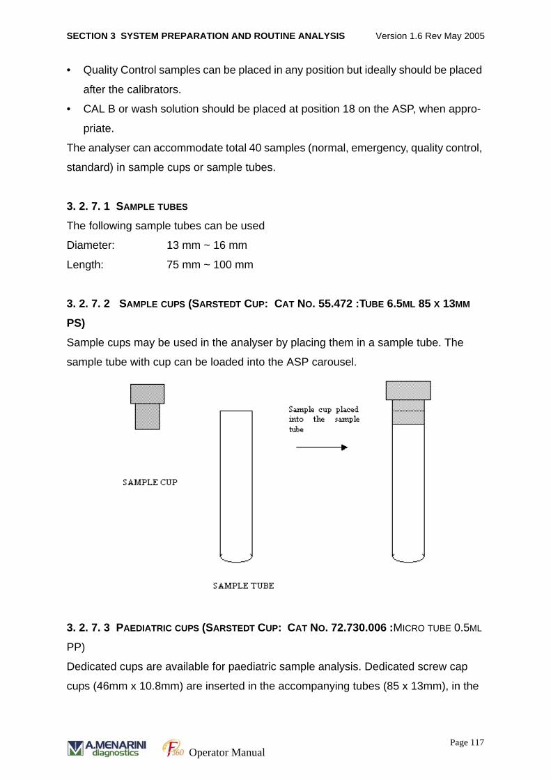
SECTION 3 SYSTEM PREPARATION AND ROUTINE ANALYSIS Version 1.6 Rev May 2005
• Quality Control samples can be placed in any position but ideally should be placed
after the calibrators.
• CAL B or wash solution should be placed at position 18 on the ASP, when appro-
priate.
The analyser can accommodate total 40 samples (normal, emergency, quality control,
standard) in sample cups or sample tubes.
3. 2. 7. 1 SAMPLE TUBES
The following sample tubes can be used
Diameter: 13 mm ~ 16 mm
Length: 75 mm ~ 100 mm
3. 2. 7. 2 SAMPLE CUPS (SARSTEDT CUP: CAT NO. 55.472 :TUBE 6.5ML 85 X 13MM
PS)
Sample cups may be used in the analyser by placing them in a sample tube. The
sample tube with cup can be loaded into the ASP carousel.
3. 2. 7. 3 PAEDIATRIC CUPS (SARSTEDT CUP: CAT NO. 72.730.006 :MICRO TUBE 0.5ML
PP)
Dedicated cups are available for paediatric sample analysis. Dedicated screw cap
cups (46mm x 10.8mm) are inserted in the accompanying tubes (85 x 13mm), in the
Page 117Operator Manual

SECTION 3 SYSTEM PREPARATION AND ROUTINE ANALYSIS Version 1.6 Rev May 2005
same way as sample cups, as presented in the diagram above. Barcodes may be
placed on the accompanying tube which can be loaded into the ASP directly.
3. 2. 8 START ANALYSIS
1. Analysis is initiated by pressing START [F1] key on the global menu.
2. A pop up screen will appear to remind the user to perform water, waste and wash
bottle checks. Click on OK.
The system will begin analysis.
The progress of analysis is displayed on the right side of the RUN MONITOR/
RUN MONITOR(F9) screen. The status of each sample is displayed using a
colour-coded system at each sample position, displayed on the left side of the
RUN MONITOR screen.
The instrument status is indicated in the STATUS field on the top left corner of the
RUN MONITOR screen.
RUN MONITOR SCREEN
The RUN MONITOR screen above also gives the following details:
• Number of tests run – This does not include QC or calibrator tests.
Page 118Operator Manual
SECTION 3 SYSTEM PREPARATION AND ROUTINE ANALYSIS Version 1.6 Rev May 2005
• Incubation temperature – Current temperature in the IRU is displayed. Sample
measurement will not proceed if the temperature is outside the specified range (37
± 0.5ºC).
• Time at start of run and estimated time at end of run. – QC and calibrator samples
will not be taken into account.
• Colour-coded system used for sample carousel.
Green – Sampling Started
Dark Blue – Range Over
Purple – Re-run required
Red – Error
Light Blue – Process completed
White – Not processed
Yellow – No Test Ordered
When the analyser is in operation the START (F1) button will flash yellow to notify the
user that the system is busy.
3. 2. 8. 1 MONITORING MEASUREMENT PROGRESS
Progress of measurement is displayed on the right side of the screen as shown in the
diagram above. The progress of each sample is displayed from sampling to the end
of the reaction. The information is displayed in columns and includes a sample type
column, Sample Number (Sno.), Method, Description and Error column.
Sample Type Column
Sample type is identified by the ‘Type’ column:
Normal or emergency sample
NONE Normal measurement (first measurement)
A> Sample re-run (greater than higher limit)
A< Sample re-run (lower than lowest limit)
D1 Diluted re-run (first measurement)
Page 119Operator Manual
SECTION 3 SYSTEM PREPARATION AND ROUTINE ANALYSIS Version 1.6 Rev May 2005
Quality control sample
C1 First measurement
Standard/Calibrator
#1 First measurement
#2 Second measurement
#3 Third measurement
Sample no. Column
Information in this column is based on the sample number type as described below.
Normal sample 0001-999999999999 (except 96000001 – 99999999)
Emergency sample Ennn (nnn = number, letter, or symbol)
Replicate sample Rnn (nnn = number, letter, or symbol)
QC sample C01-C30
Calibrator S000011 - S999997
Multi-Calibrator MS01 - MS97
Single calibrator SS000011 - SS999997
Blank Sample B
Method Column
Method name is displayed.
Patient ID Column
Patient ID is displayed.
Result Column
Result is displayed when analysis is complete (excludes ISE and replicate samples)
Page 120Operator Manual
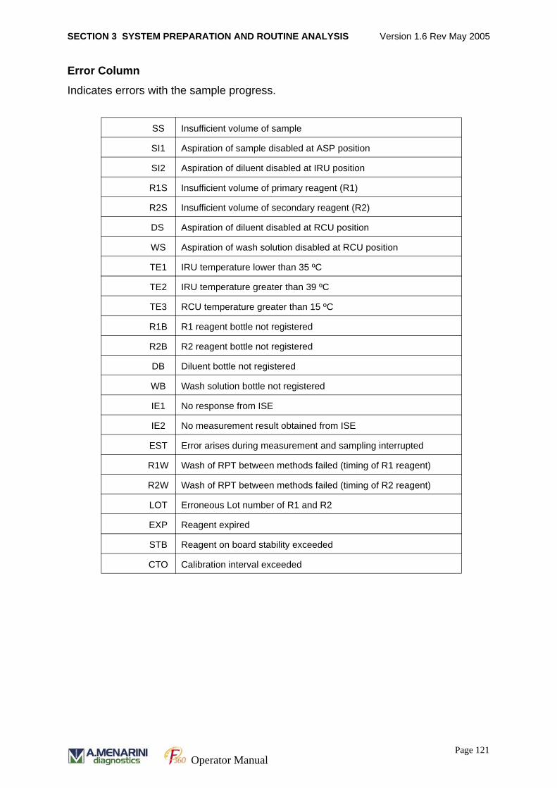
SECTION 3 SYSTEM PREPARATION AND ROUTINE ANALYSIS Version 1.6 Rev May 2005
Error Column
Indicates errors with the sample progress.
SS Insufficient volume of sample
SI1 Aspiration of sample disabled at ASP position
SI2 Aspiration of diluent disabled at IRU position
R1S Insufficient volume of primary reagent (R1)
R2S Insufficient volume of secondary reagent (R2)
DS Aspiration of diluent disabled at RCU position
WS Aspiration of wash solution disabled at RCU position
TE1 IRU temperature lower than 35 ºC
TE2 IRU temperature greater than 39 ºC
TE3 RCU temperature greater than 15 ºC
R1B R1 reagent bottle not registered
R2B R2 reagent bottle not registered
DB Diluent bottle not registered
WB Wash solution bottle not registered
IE1 No response from ISE
IE2 No measurement result obtained from ISE
EST Error arises during measurement and sampling interrupted
R1W Wash of RPT between methods failed (timing of R1 reagent)
R2W Wash of RPT between methods failed (timing of R2 reagent)
LOT Erroneous Lot number of R1 and R2
EXP Reagent expired
STB Reagent on board stability exceeded
CTO Calibration interval exceeded
Page 121Operator Manual
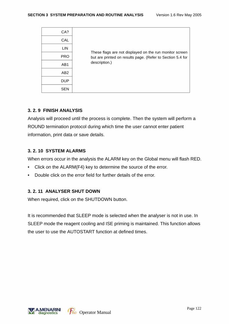
SECTION 3 SYSTEM PREPARATION AND ROUTINE ANALYSIS Version 1.6 Rev May 2005
3. 2. 9 FINISH ANALYSIS
Analysis will proceed until the process is complete. Then the system will perform a
ROUND termination protocol during which time the user cannot enter patient
information, print data or save details.
3. 2. 10 SYSTEM ALARMS
When errors occur in the analysis the ALARM key on the Global menu will flash RED.
• Click on the ALARM(F4) key to determine the source of the error.
• Double click on the error field for further details of the error.
3. 2. 11 ANALYSER SHUT DOWN
When required, click on the SHUTDOWN button.
It is recommended that SLEEP mode is selected when the analyser is not in use. In
SLEEP mode the reagent cooling and ISE priming is maintained. This function allows
the user to use the AUTOSTART function at defined times.
CA?
These flags are not displayed on the run monitor screenbut are printed on results page. (Refer to Section 5.4 fordescription.)
CAL
LIN
PRO
AB1
AB2
DUP
SEN
Page 122Operator Manual
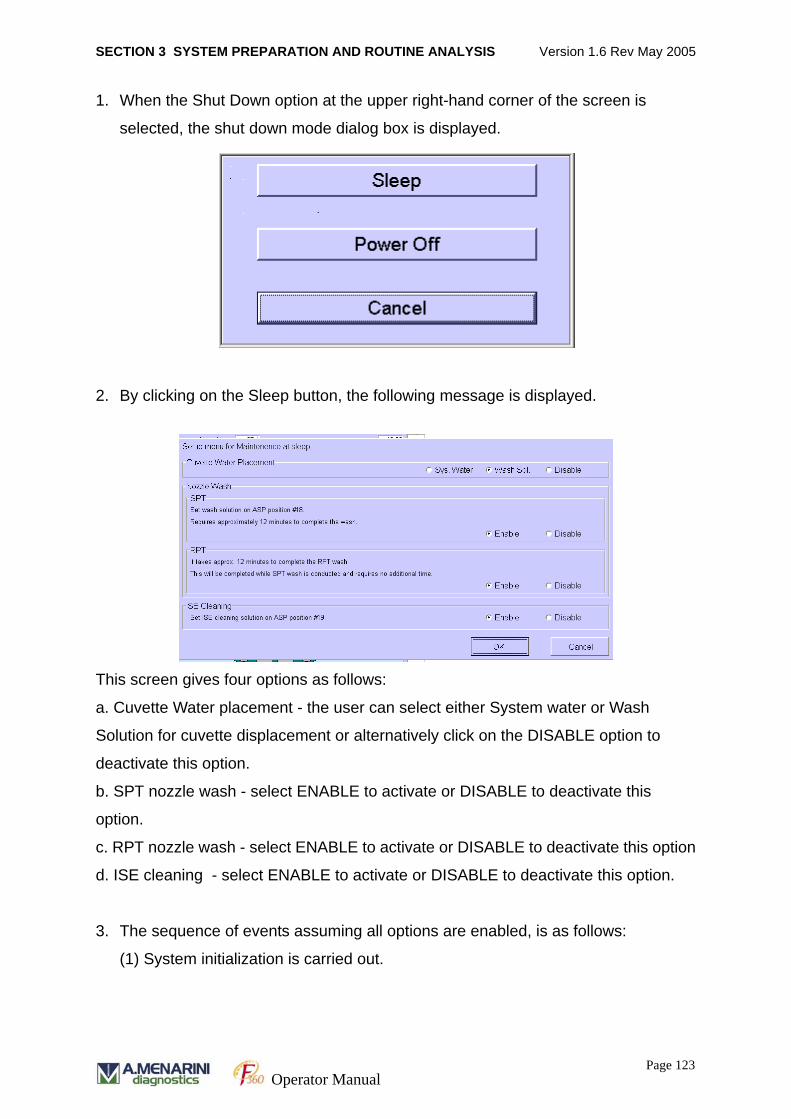
SECTION 3 SYSTEM PREPARATION AND ROUTINE ANALYSIS Version 1.6 Rev May 2005
1. When the Shut Down option at the upper right-hand corner of the screen is
selected, the shut down mode dialog box is displayed.
2. By clicking on the Sleep button, the following message is displayed.
This screen gives four options as follows:
a. Cuvette Water placement - the user can select either System water or Wash
Solution for cuvette displacement or alternatively click on the DISABLE option to
deactivate this option.
b. SPT nozzle wash - select ENABLE to activate or DISABLE to deactivate this
option.
c. RPT nozzle wash - select ENABLE to activate or DISABLE to deactivate this option
d. ISE cleaning - select ENABLE to activate or DISABLE to deactivate this option.
3. The sequence of events assuming all options are enabled, is as follows:
(1) System initialization is carried out.
Page 123Operator Manual
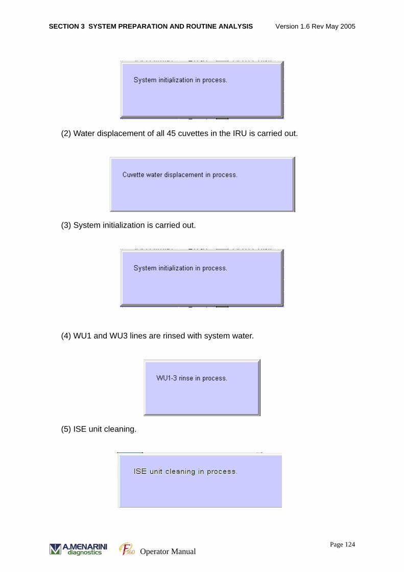
SECTION 3 SYSTEM PREPARATION AND ROUTINE ANALYSIS Version 1.6 Rev May 2005
(2) Water displacement of all 45 cuvettes in the IRU is carried out.
(3) System initialization is carried out.
(4) WU1 and WU3 lines are rinsed with system water.
(5) ISE unit cleaning.
Page 124Operator Manual
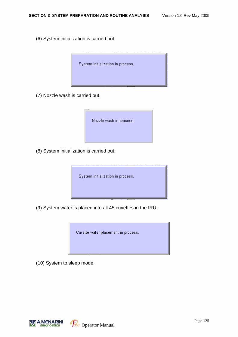
SECTION 3 SYSTEM PREPARATION AND ROUTINE ANALYSIS Version 1.6 Rev May 2005
(6) System initialization is carried out.
(7) Nozzle wash is carried out.
(8) System initialization is carried out.
(9) System water is placed into all 45 cuvettes in the IRU.
(10) System to sleep mode.
Page 125Operator Manual
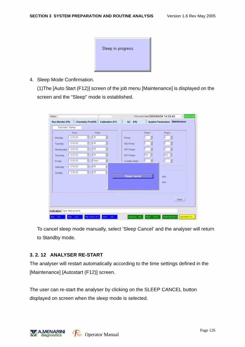
SECTION 3 SYSTEM PREPARATION AND ROUTINE ANALYSIS Version 1.6 Rev May 2005
4. Sleep Mode Confirmation.
(1)The [Auto Start (F12)] screen of the job menu [Maintenance] is displayed on the
screen and the “Sleep” mode is established.
To cancel sleep mode manually, select ‘Sleep Cancel’ and the analyser will return
to Standby mode.
3. 2. 12 ANALYSER RE-START
The analyser will restart automatically according to the time settings defined in the
[Maintenance] [Autostart (F12)] screen.
The user can re-start the analyser by clicking on the SLEEP CANCEL button
displayed on screen when the sleep mode is selected.
Page 126Operator Manual

SECTION 3 SYSTEM PREPARATION AND ROUTINE ANALYSIS Version 1.6 Rev May 2005
POWER OFF should only be used when the instrument is serviced or if the
instrument will not be in use for an extended period of time.
WARNING If POWER OFF is selected the reagents will not be cooled and the ISEs
may dry out and become unusable.
Page 127Operator Manual

SECTION 3 SYSTEM PREPARATION AND ROUTINE ANALYSIS Version 1.6 Rev May 2005
Page 128Operator Manual
SECTION 4 ACCESSORY OPERATIONAL FUNCTIONS Version 1.6 Rev May 2005
SECTION 4
ACCESSORY OPERATIONAL FUNCTIONS
Page 129
Operator Manual
SECTION 4 ACCESSORY OPERATIONAL FUNCTIONS Version 1.6 Rev May 2005
4.1 INTERRUPTION AND RESUMPTION OF
MEASUREMENTThis section describes the accessory operational functions available with the system.
These functions are in addition to the routine operation of the system.
During routine operation analysis may be interrupted and resumed manually.
4. 1. 1 EMERGENCY STOP
An emergency stop may be initiated if there is a severe malfunction with the analyser.
When this is initiated, unprocessed data from the run will not be retrievable.
• Press [CONTROL] and STOP [F2] simultaneously to initiate an emergency stop.
In some circumstances the system will automatically initiate an emergency stop.
• After the emergency stop has been initiated the analyser will perform system ini-
tialisation and then perform a cuvette wash to clean those cuvettes that were used
during measurement.
• The STATUS field in the top left corner of the RUN MONITOR screen will display
the message ‘Emergency Stop in progress’.
4. 1. 2 INTERRUPTION OF SAMPLING
Sampling may be interrupted for two reasons; to add more samples or load
emergency samples.
4. 1. 2. 1 SAMPLE INTERRUPTION TO LOAD EMERGENCY SAMPLES
This enables the user to load emergency samples into the sample carousel during
analysis. When this mode of interruption is utilised the analyser will stop analysis
immediately and perform analysis of the emergency samples before resuming routine
sampling.
Normal samples may be added using this facility if the user wants to give them priority
of analysis, if the system is operated in a non-barcode mode.
Page 130
Operator Manual
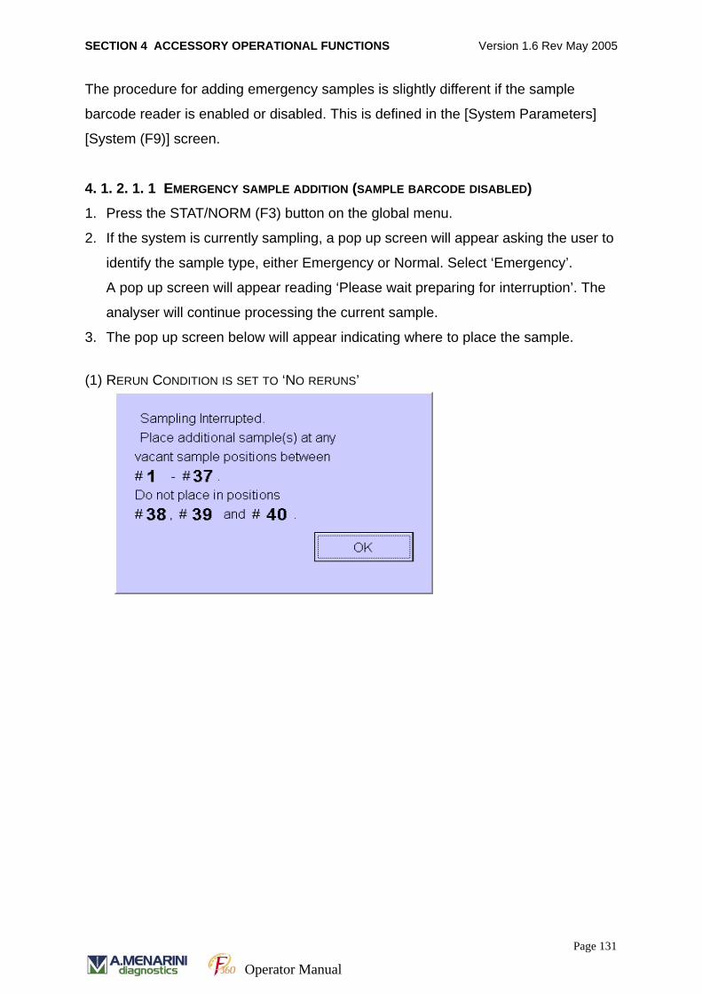
SECTION 4 ACCESSORY OPERATIONAL FUNCTIONS Version 1.6 Rev May 2005
The procedure for adding emergency samples is slightly different if the sample
barcode reader is enabled or disabled. This is defined in the [System Parameters]
[System (F9)] screen.
4. 1. 2. 1. 1 EMERGENCY SAMPLE ADDITION (SAMPLE BARCODE DISABLED)
1. Press the STAT/NORM (F3) button on the global menu.
2. If the system is currently sampling, a pop up screen will appear asking the user to
identify the sample type, either Emergency or Normal. Select ‘Emergency’.
A pop up screen will appear reading ‘Please wait preparing for interruption’. The
analyser will continue processing the current sample.
3. The pop up screen below will appear indicating where to place the sample.
(1) RERUN CONDITION IS SET TO ‘NO RERUNS’
Page 131
Operator Manual
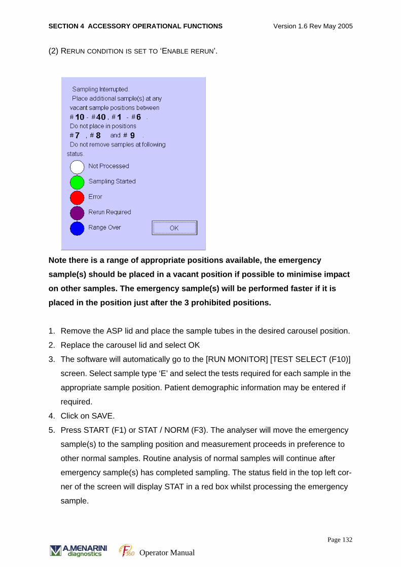
SECTION 4 ACCESSORY OPERATIONAL FUNCTIONS Version 1.6 Rev May 2005
(2) RERUN CONDITION IS SET TO ‘ENABLE RERUN’.
Note there is a range of appropriate positions available, the emergency
sample(s) should be placed in a vacant position if possible to minimise impact
on other samples. The emergency sample(s) will be performed faster if it is
placed in the position just after the 3 prohibited positions.
1. Remove the ASP lid and place the sample tubes in the desired carousel position.
2. Replace the carousel lid and select OK
3. The software will automatically go to the [RUN MONITOR] [TEST SELECT (F10)]
screen. Select sample type ‘E’ and select the tests required for each sample in the
appropriate sample position. Patient demographic information may be entered if
required.
4. Click on SAVE.
5. Press START (F1) or STAT / NORM (F3). The analyser will move the emergency
sample(s) to the sampling position and measurement proceeds in preference to
other normal samples. Routine analysis of normal samples will continue after
emergency sample(s) has completed sampling. The status field in the top left cor-
ner of the screen will display STAT in a red box whilst processing the emergency
sample.
Page 132
Operator Manual

SECTION 4 ACCESSORY OPERATIONAL FUNCTIONS Version 1.6 Rev May 2005
4. 1. 2. 1. 2 EMERGENCY SAMPLE ADDITION (SAMPLE BARCODE ENABLED)
1. Select RUN MONITOR [F6] on the job menu.
2. Select TEST SELECT [F10] on the function keys.
3. Select the test select screen. Click on Page 1/2 for a NORMAL sample or
page 2/2 for an Emergency sample. Enter appropriate emergency barcode number
and select the tests required for each sample (as described in the test selection
section of this manual).
4. Repeat for each emergency sample to be assayed.
5. Press the STAT/NORM (F3) button on the global menu.
6. If the system is currently sampling, a pop up screen will appear asking the user to
identify the sample type, either Emergency or Normal. Select ‘Emergency’.
The following screen will appear reading ‘Please wait preparing for interruption’.
A pop up screen will state ‘Sampling Interrupted’ and will indicate where to place
the sample tubes.
(1) RERUN CONDITION IS SET TO ‘NO RERUNS’
Page 133
Operator Manual
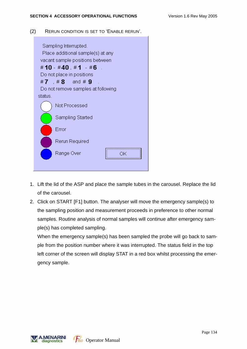
SECTION 4 ACCESSORY OPERATIONAL FUNCTIONS Version 1.6 Rev May 2005
(2) RERUN CONDITION IS SET TO ‘ENABLE RERUN’.
1. Lift the lid of the ASP and place the sample tubes in the carousel. Replace the lid
of the carousel.
2. Click on START [F1] button. The analyser will move the emergency sample(s) to
the sampling position and measurement proceeds in preference to other normal
samples. Routine analysis of normal samples will continue after emergency sam-
ple(s) has completed sampling.
When the emergency sample(s) has been sampled the probe will go back to sam-
ple from the position number where it was interrupted. The status field in the top
left corner of the screen will display STAT in a red box whilst processing the emer-
gency sample.
Page 134
Operator Manual
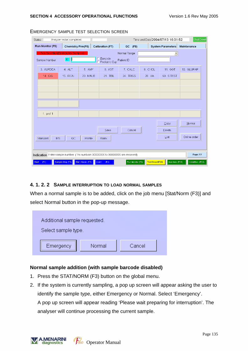
SECTION 4 ACCESSORY OPERATIONAL FUNCTIONS Version 1.6 Rev May 2005
EMERGENCY SAMPLE TEST SELECTION SCREEN
4. 1. 2. 2 SAMPLE INTERRUPTION TO LOAD NORMAL SAMPLES
When a normal sample is to be added, click on the job menu [Stat/Norm (F3)] and
select Normal button in the pop-up message.
Normal sample addition (with sample barcode disabled)
1. Press the STAT/NORM (F3) button on the global menu.
2. If the system is currently sampling, a pop up screen will appear asking the user to
identify the sample type, either Emergency or Normal. Select ‘Emergency’.
A pop up screen will appear reading ‘Please wait preparing for interruption’. The
analyser will continue processing the current sample.
Page 135
Operator Manual
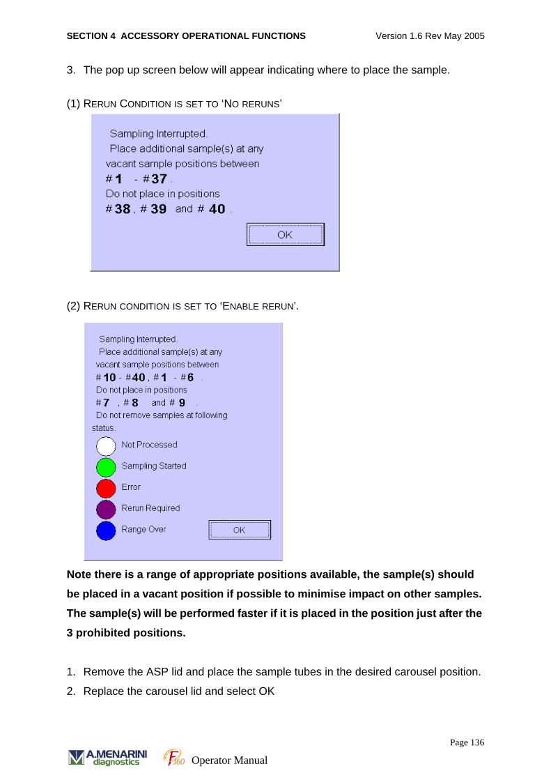
SECTION 4 ACCESSORY OPERATIONAL FUNCTIONS Version 1.6 Rev May 2005
3. The pop up screen below will appear indicating where to place the sample.
(1) RERUN CONDITION IS SET TO ‘NO RERUNS’
(2) RERUN CONDITION IS SET TO ‘ENABLE RERUN’.
Note there is a range of appropriate positions available, the sample(s) should
be placed in a vacant position if possible to minimise impact on other samples.
The sample(s) will be performed faster if it is placed in the position just after the
3 prohibited positions.
1. Remove the ASP lid and place the sample tubes in the desired carousel position.
2. Replace the carousel lid and select OK
Page 136
Operator Manual
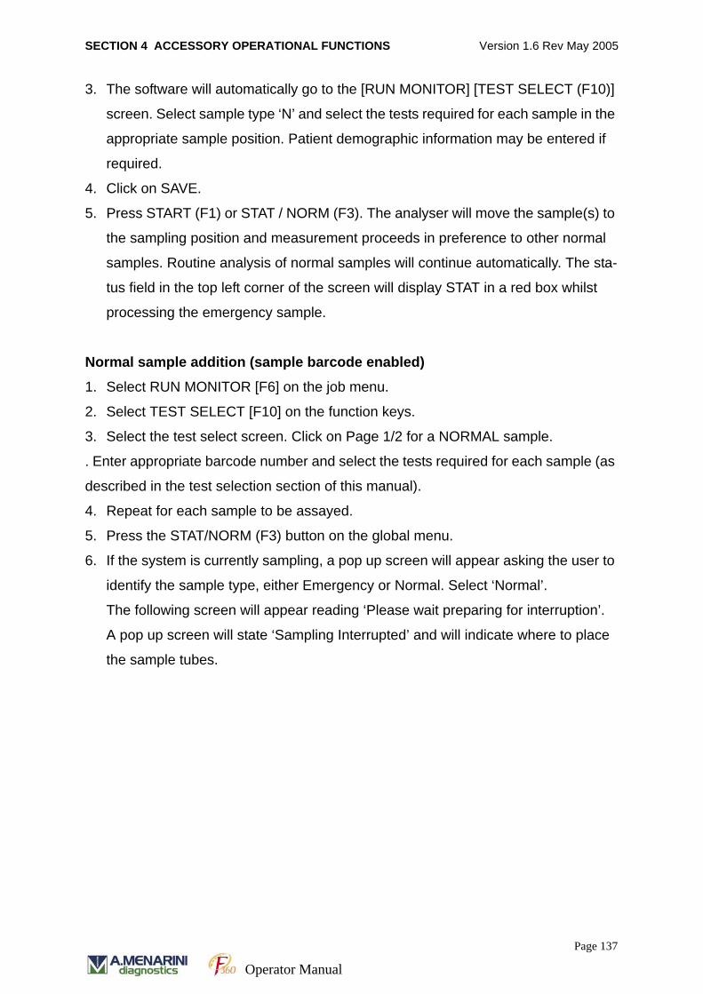
SECTION 4 ACCESSORY OPERATIONAL FUNCTIONS Version 1.6 Rev May 2005
3. The software will automatically go to the [RUN MONITOR] [TEST SELECT (F10)]
screen. Select sample type ‘N’ and select the tests required for each sample in the
appropriate sample position. Patient demographic information may be entered if
required.
4. Click on SAVE.
5. Press START (F1) or STAT / NORM (F3). The analyser will move the sample(s) to
the sampling position and measurement proceeds in preference to other normal
samples. Routine analysis of normal samples will continue automatically. The sta-
tus field in the top left corner of the screen will display STAT in a red box whilst
processing the emergency sample.
Normal sample addition (sample barcode enabled)
1. Select RUN MONITOR [F6] on the job menu.
2. Select TEST SELECT [F10] on the function keys.
3. Select the test select screen. Click on Page 1/2 for a NORMAL sample.
. Enter appropriate barcode number and select the tests required for each sample (as
described in the test selection section of this manual).
4. Repeat for each sample to be assayed.
5. Press the STAT/NORM (F3) button on the global menu.
6. If the system is currently sampling, a pop up screen will appear asking the user to
identify the sample type, either Emergency or Normal. Select ‘Normal’.
The following screen will appear reading ‘Please wait preparing for interruption’.
A pop up screen will state ‘Sampling Interrupted’ and will indicate where to place
the sample tubes.
Page 137
Operator Manual
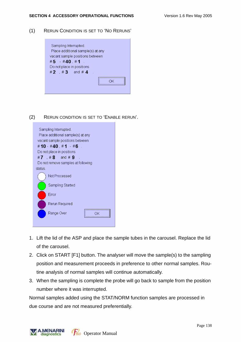
SECTION 4 ACCESSORY OPERATIONAL FUNCTIONS Version 1.6 Rev May 2005
(1) RERUN CONDITION IS SET TO ‘NO RERUNS’
(2) RERUN CONDITION IS SET TO ‘ENABLE RERUN’.
1. Lift the lid of the ASP and place the sample tubes in the carousel. Replace the lid
of the carousel.
2. Click on START [F1] button. The analyser will move the sample(s) to the sampling
position and measurement proceeds in preference to other normal samples. Rou-
tine analysis of normal samples will continue automatically.
3. When the sampling is complete the probe will go back to sample from the position
number where it was interrupted.
Normal samples added using the STAT/NORM function samples are processed in
due course and are not measured preferentially.
Page 138
Operator Manual
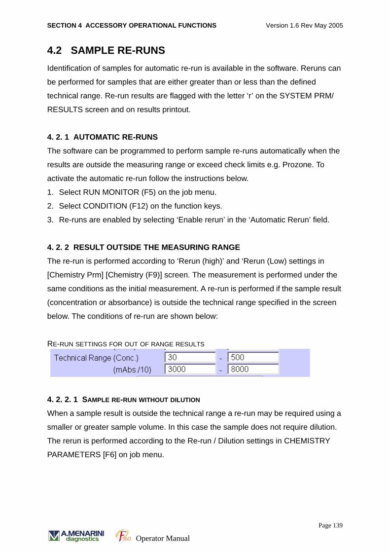
SECTION 4 ACCESSORY OPERATIONAL FUNCTIONS Version 1.6 Rev May 2005
4.2 SAMPLE RE-RUNSIdentification of samples for automatic re-run is available in the software. Reruns can
be performed for samples that are either greater than or less than the defined
technical range. Re-run results are flagged with the letter ‘r’ on the SYSTEM PRM/
RESULTS screen and on results printout.
4. 2. 1 AUTOMATIC RE-RUNS
The software can be programmed to perform sample re-runs automatically when the
results are outside the measuring range or exceed check limits e.g. Prozone. To
activate the automatic re-run follow the instructions below.
1. Select RUN MONITOR (F5) on the job menu.
2. Select CONDITION (F12) on the function keys.
3. Re-runs are enabled by selecting ‘Enable rerun’ in the ‘Automatic Rerun’ field.
4. 2. 2 RESULT OUTSIDE THE MEASURING RANGE
The re-run is performed according to ‘Rerun (high)’ and ‘Rerun (Low) settings in
[Chemistry Prm] [Chemistry (F9)] screen. The measurement is performed under the
same conditions as the initial measurement. A re-run is performed if the sample result
(concentration or absorbance) is outside the technical range specified in the screen
below. The conditions of re-run are shown below:
RE-RUN SETTINGS FOR OUT OF RANGE RESULTS
4. 2. 2. 1 SAMPLE RE-RUN WITHOUT DILUTION
When a sample result is outside the technical range a re-run may be required using a
smaller or greater sample volume. In this case the sample does not require dilution.
The rerun is performed according to the Re-run / Dilution settings in CHEMISTRY
PARAMETERS [F6] on job menu.
Page 139
Operator Manual
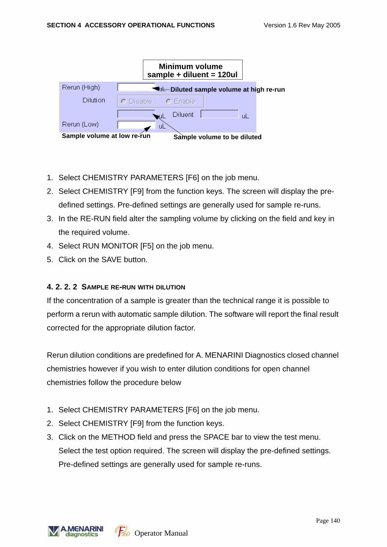
SECTION 4 ACCESSORY OPERATIONAL FUNCTIONS Version 1.6 Rev May 2005
1. Select CHEMISTRY PARAMETERS [F6] on the job menu.
2. Select CHEMISTRY [F9] from the function keys. The screen will display the pre-
defined settings. Pre-defined settings are generally used for sample re-runs.
3. In the RE-RUN field alter the sampling volume by clicking on the field and key in
the required volume.
4. Select RUN MONITOR [F5] on the job menu.
5. Click on the SAVE button.
4. 2. 2. 2 SAMPLE RE-RUN WITH DILUTION
If the concentration of a sample is greater than the technical range it is possible to
perform a rerun with automatic sample dilution. The software will report the final result
corrected for the appropriate dilution factor.
Rerun dilution conditions are predefined for A. MENARINI Diagnostics closed channel
chemistries however if you wish to enter dilution conditions for open channel
chemistries follow the procedure below
1. Select CHEMISTRY PARAMETERS [F6] on the job menu.
2. Select CHEMISTRY [F9] from the function keys.
3. Click on the METHOD field and press the SPACE bar to view the test menu.
Select the test option required. The screen will display the pre-defined settings.
Pre-defined settings are generally used for sample re-runs.
Sample volume to be dilutedSample volume at low re-run
Minimum volumesample + diluent = 120ul
Diluted sample volume at high re-run
Page 140
Operator Manual
SECTION 4 ACCESSORY OPERATIONAL FUNCTIONS Version 1.6 Rev May 2005
4. In the DILUENT field click on the option ENABLE and then click on the Reagent
Name field. Press the SPACE bar to view the diluent name options (SALINE is the
usual option).
5. In the DILUTION field click on the ENABLE option. Enter the volume of neat sam-
ple and the diluent volume in the fields below. A minimum total volume (sample +
diluent) of 120μl should be specified.
6. In the RE-RUN field enter the sampling volume (of diluted sample) required.
7. Click on the SAVE button.
NB Automatic sample dilution conditions cannot be entered unless a diluent is
enabled and selected.
Page 141
Operator Manual
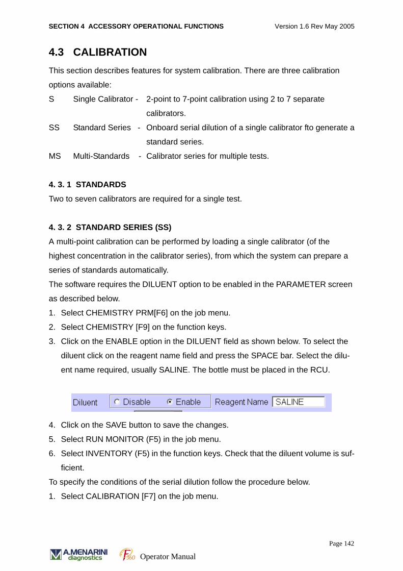
SECTION 4 ACCESSORY OPERATIONAL FUNCTIONS Version 1.6 Rev May 2005
4.3 CALIBRATIONThis section describes features for system calibration. There are three calibration
options available:
S Single Calibrator - 2-point to 7-point calibration using 2 to 7 separate
calibrators.
SS Standard Series - Onboard serial dilution of a single calibrator fto generate a
standard series.
MS Multi-Standards - Calibrator series for multiple tests.
4. 3. 1 STANDARDS
Two to seven calibrators are required for a single test.
4. 3. 2 STANDARD SERIES (SS)
A multi-point calibration can be performed by loading a single calibrator (of the
highest concentration in the calibrator series), from which the system can prepare a
series of standards automatically.
The software requires the DILUENT option to be enabled in the PARAMETER screen
as described below.
1. Select CHEMISTRY PRM[F6] on the job menu.
2. Select CHEMISTRY [F9] on the function keys.
3. Click on the ENABLE option in the DILUENT field as shown below. To select the
diluent click on the reagent name field and press the SPACE bar. Select the dilu-
ent name required, usually SALINE. The bottle must be placed in the RCU.
4. Click on the SAVE button to save the changes.
5. Select RUN MONITOR (F5) in the job menu.
6. Select INVENTORY (F5) in the function keys. Check that the diluent volume is suf-
ficient.
To specify the conditions of the serial dilution follow the procedure below.
1. Select CALIBRATION [F7] on the job menu.
Page 142
Operator Manual

SECTION 4 ACCESSORY OPERATIONAL FUNCTIONS Version 1.6 Rev May 2005
2. Select CALIBRATION (F9) of the function keys. Click on the SPACE bar, place the
cursor on the test required and double click to select the test.
3. Click on the PARAMETERS button. Enter the desired concentration of each stan-
dard in the series. The concentration of the highest standard loaded onto the sam-
ple carousel is entered against the last standard position number in the series.
4. For example if there are 6 standards in the series the highest concentration should
be entered in position number S6. When entering concentrations please note that
for auto dilution:
minimum volume of [sample + diluent] = 80μl
maximum pre-sampling volume = 35μl
For example if the neat sample had a concentration
of 30 mmol/l then the following standard concentrations would be prepared:
Standard Concentration Calculation
Standard solution 1 0
Standard solution 2 1.875 (0.0625 * 30)
Standard solution 3 3.75 (0.125 * 30)
Standard solution 4 7.5 (0.25 * 30)
Standard solution 5 13.125 (0.4375 * 30)
Standard solution 6 30 (1 * 30)
5. Select PAGE 2/2 to display the following screen.
Page 143
Operator Manual
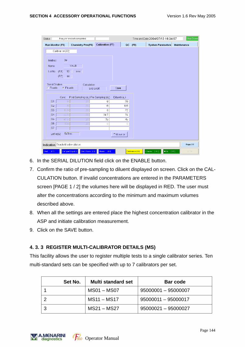
SECTION 4 ACCESSORY OPERATIONAL FUNCTIONS Version 1.6 Rev May 2005
6. In the SERIAL DILUTION field click on the ENABLE button.
7. Confirm the ratio of pre-sampling to diluent displayed on screen. Click on the CAL-
CULATION button. If invalid concentrations are entered in the PARAMETERS
screen [PAGE 1 / 2] the volumes here will be displayed in RED. The user must
alter the concentrations according to the minimum and maximum volumes
described above.
8. When all the settings are entered place the highest concentration calibrator in the
ASP and initiate calibration measurement.
9. Click on the SAVE button.
4. 3. 3 REGISTER MULTI-CALIBRATOR DETAILS (MS)
This facility allows the user to register multiple tests to a single calibrator series. Ten
multi-standard sets can be specified with up to 7 calibrators per set.
Set No. Multi standard set Bar code1 MS01 – MS07 95000001 – 95000007
2 MS11 – MS17 95000011 – 95000017
3 MS21 – MS27 95000021 – 95000027
Page 144
Operator Manual
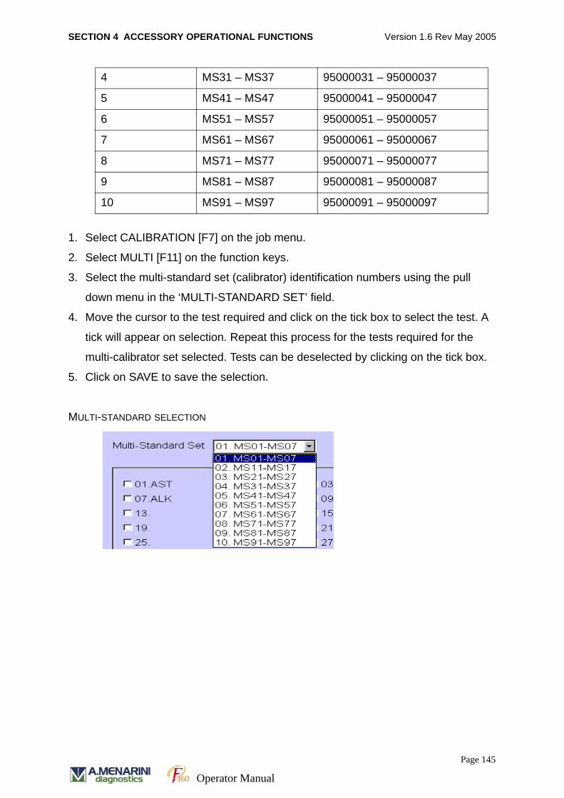
SECTION 4 ACCESSORY OPERATIONAL FUNCTIONS Version 1.6 Rev May 2005
1. Select CALIBRATION [F7] on the job menu.
2. Select MULTI [F11] on the function keys.
3. Select the multi-standard set (calibrator) identification numbers using the pull
down menu in the ‘MULTI-STANDARD SET’ field.
4. Move the cursor to the test required and click on the tick box to select the test. A
tick will appear on selection. Repeat this process for the tests required for the
multi-calibrator set selected. Tests can be deselected by clicking on the tick box.
5. Click on SAVE to save the selection.
MULTI-STANDARD SELECTION
4 MS31 – MS37 95000031 – 95000037
5 MS41 – MS47 95000041 – 95000047
6 MS51 – MS57 95000051 – 95000057
7 MS61 – MS67 95000061 – 95000067
8 MS71 – MS77 95000071 – 95000077
9 MS81 – MS87 95000081 – 95000087
10 MS91 – MS97 95000091 – 95000097
Page 145
Operator Manual
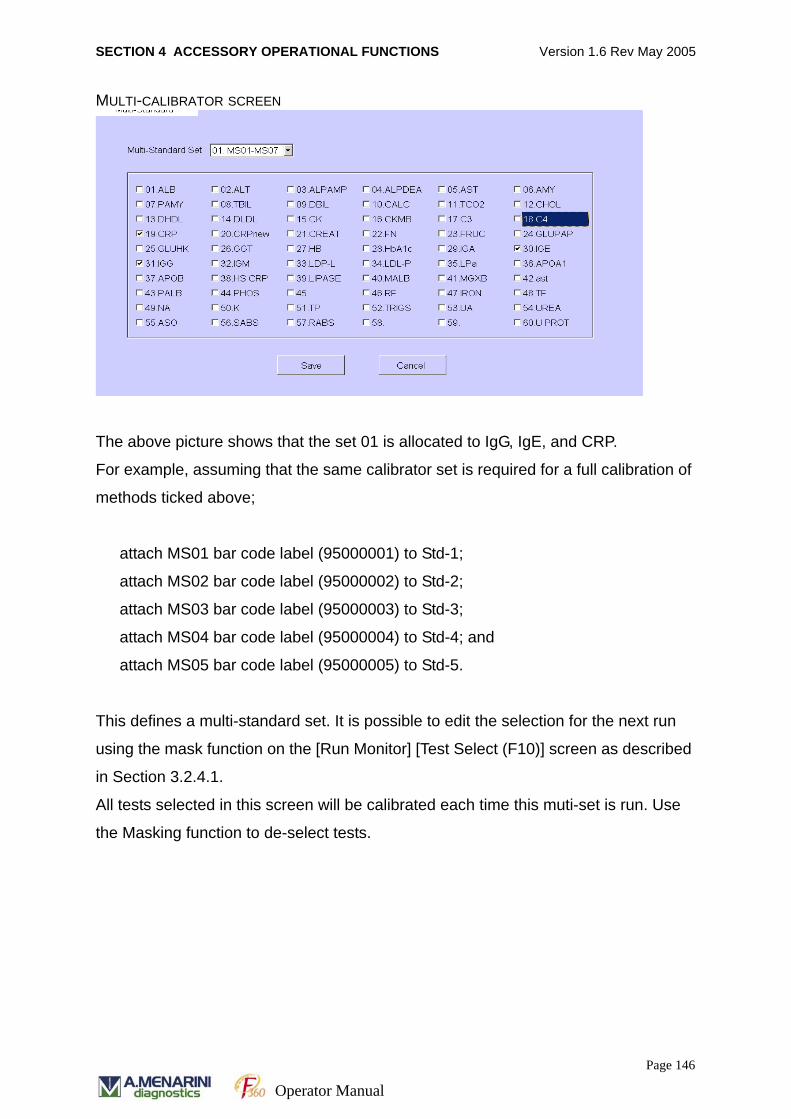
SECTION 4 ACCESSORY OPERATIONAL FUNCTIONS Version 1.6 Rev May 2005
MULTI-CALIBRATOR SCREEN
The above picture shows that the set 01 is allocated to IgG, IgE, and CRP.
For example, assuming that the same calibrator set is required for a full calibration of
methods ticked above;
attach MS01 bar code label (95000001) to Std-1;
attach MS02 bar code label (95000002) to Std-2;
attach MS03 bar code label (95000003) to Std-3;
attach MS04 bar code label (95000004) to Std-4; and
attach MS05 bar code label (95000005) to Std-5.
This defines a multi-standard set. It is possible to edit the selection for the next run
using the mask function on the [Run Monitor] [Test Select (F10)] screen as described
in Section 3.2.4.1.
All tests selected in this screen will be calibrated each time this muti-set is run. Use
the Masking function to de-select tests.
Page 146
Operator Manual
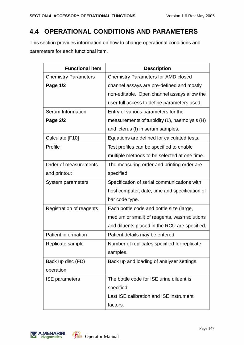
SECTION 4 ACCESSORY OPERATIONAL FUNCTIONS Version 1.6 Rev May 2005
4.4 OPERATIONAL CONDITIONS AND PARAMETERSThis section provides information on how to change operational conditions and
parameters for each functional item.
Functional item DescriptionChemistry Parameters
Page 1/2
Chemistry Parameters for AMD closed
channel assays are pre-defined and mostly
non-editable. Open channel assays allow the
user full access to define parameters used.
Serum Information
Page 2/2
Entry of various parameters for the
measurements of turbidity (L), haemolysis (H)
and icterus (I) in serum samples.
Calculate [F10] Equations are defined for calculated tests.
Profile Test profiles can be specified to enable
multiple methods to be selected at one time.
Order of measurements
and printout
The measuring order and printing order are
specified.
System parameters Specification of serial communications with
host computer, date, time and specification of
bar code type.
Registration of reagents Each bottle code and bottle size (large,
medium or small) of reagents, wash solutions
and diluents placed in the RCU are specified.
Patient information Patient details may be entered.
Replicate sample Number of replicates specified for replicate
samples.
Back up disc (FD)
operation
Back up and loading of analyser settings.
ISE parameters The bottle code for ISE urine diluent is
specified.
Last ISE calibration and ISE instrument
factors.
Page 147
Operator Manual
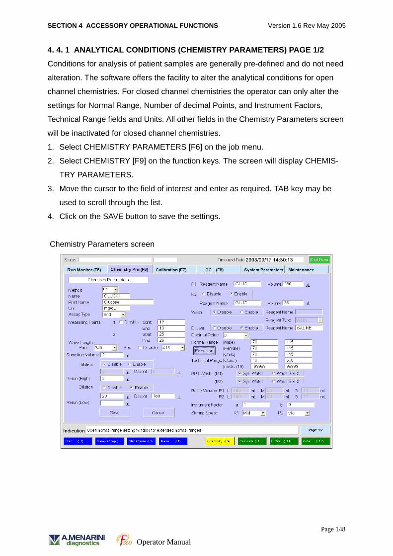
SECTION 4 ACCESSORY OPERATIONAL FUNCTIONS Version 1.6 Rev May 2005
4. 4. 1 ANALYTICAL CONDITIONS (CHEMISTRY PARAMETERS) PAGE 1/2
Conditions for analysis of patient samples are generally pre-defined and do not need
alteration. The software offers the facility to alter the analytical conditions for open
channel chemistries. For closed channel chemistries the operator can only alter the
settings for Normal Range, Number of decimal Points, and Instrument Factors,
Technical Range fields and Units. All other fields in the Chemistry Parameters screen
will be inactivated for closed channel chemistries.
1. Select CHEMISTRY PARAMETERS [F6] on the job menu.
2. Select CHEMISTRY [F9] on the function keys. The screen will display CHEMIS-
TRY PARAMETERS.
3. Move the cursor to the field of interest and enter as required. TAB key may be
used to scroll through the list.
4. Click on the SAVE button to save the settings.
Chemistry Parameters screen
Page 148
Operator Manual
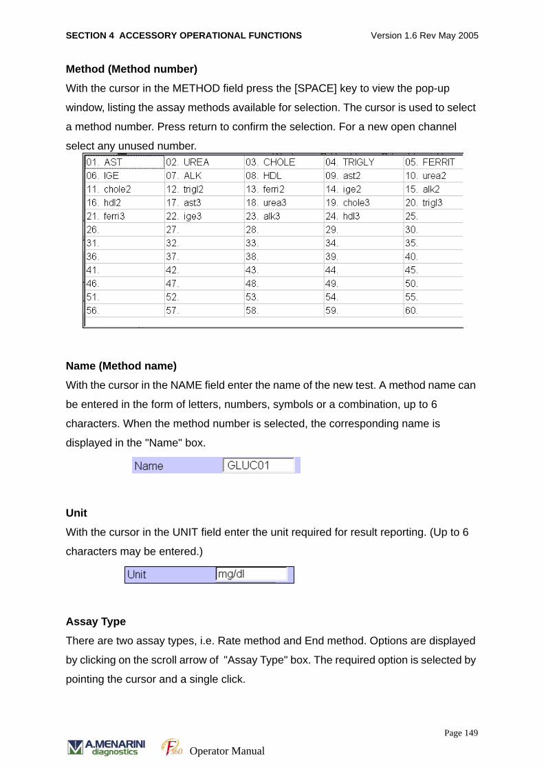
SECTION 4 ACCESSORY OPERATIONAL FUNCTIONS Version 1.6 Rev May 2005
Method (Method number)
With the cursor in the METHOD field press the [SPACE] key to view the pop-up
window, listing the assay methods available for selection. The cursor is used to select
a method number. Press return to confirm the selection. For a new open channel
select any unused number.
Name (Method name)
With the cursor in the NAME field enter the name of the new test. A method name can
be entered in the form of letters, numbers, symbols or a combination, up to 6
characters. When the method number is selected, the corresponding name is
displayed in the "Name" box.
Unit
With the cursor in the UNIT field enter the unit required for result reporting. (Up to 6
characters may be entered.)
Assay Type
There are two assay types, i.e. Rate method and End method. Options are displayed
by clicking on the scroll arrow of "Assay Type" box. The required option is selected by
pointing the cursor and a single click.
Page 149
Operator Manual
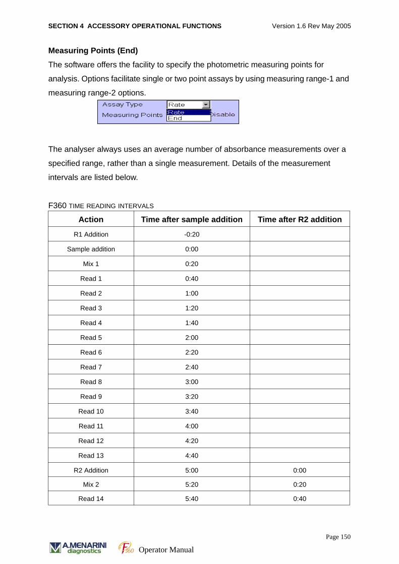
SECTION 4 ACCESSORY OPERATIONAL FUNCTIONS Version 1.6 Rev May 2005
Measuring Points (End)
The software offers the facility to specify the photometric measuring points for
analysis. Options facilitate single or two point assays by using measuring range-1 and
measuring range-2 options.
The analyser always uses an average number of absorbance measurements over a
specified range, rather than a single measurement. Details of the measurement
intervals are listed below.
F360 TIME READING INTERVALS
Action Time after sample addition Time after R2 addition
R1 Addition -0:20
Sample addition 0:00
Mix 1 0:20
Read 1 0:40
Read 2 1:00
Read 3 1:20
Read 4 1:40
Read 5 2:00
Read 6 2:20
Read 7 2:40
Read 8 3:00
Read 9 3:20
Read 10 3:40
Read 11 4:00
Read 12 4:20
Read 13 4:40
R2 Addition 5:00 0:00
Mix 2 5:20 0:20
Read 14 5:40 0:40
Page 150
Operator Manual
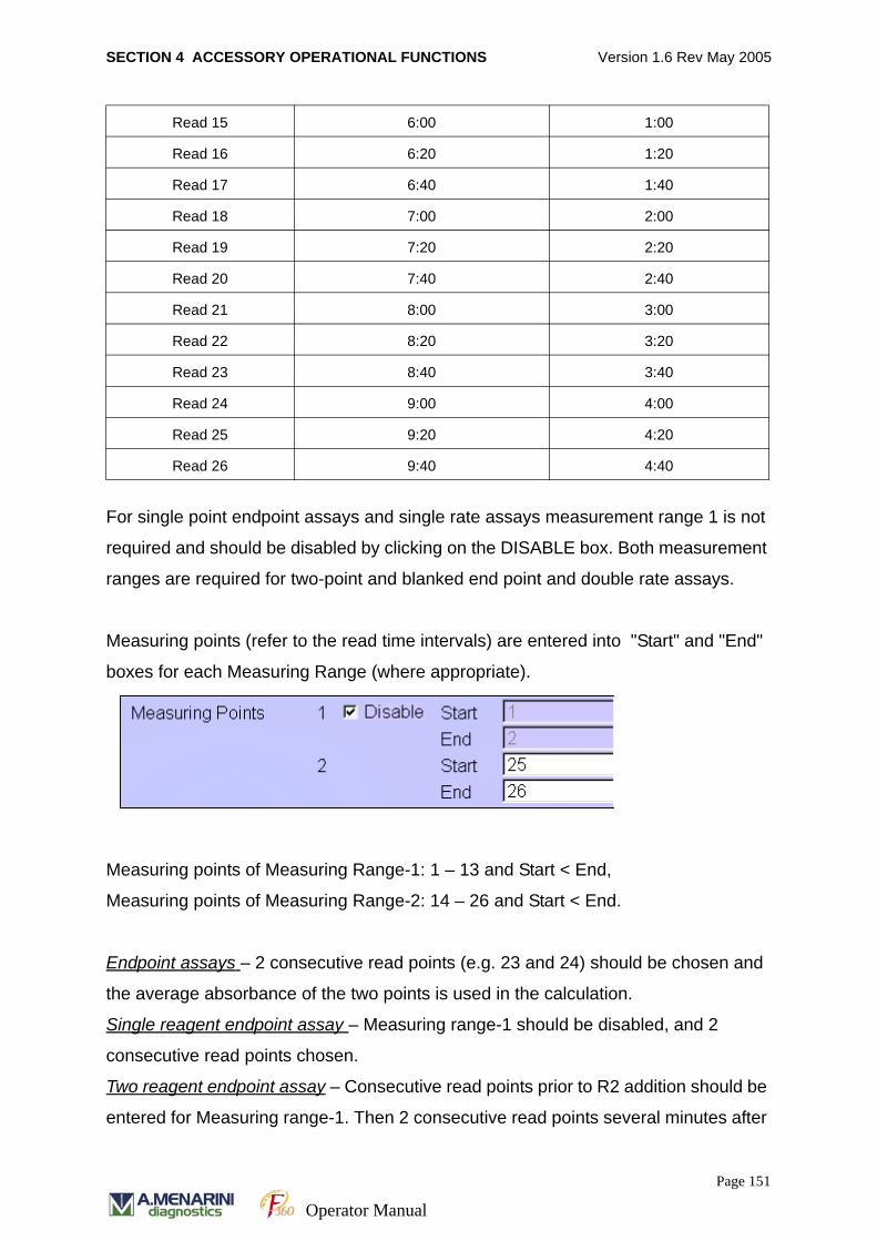
SECTION 4 ACCESSORY OPERATIONAL FUNCTIONS Version 1.6 Rev May 2005
For single point endpoint assays and single rate assays measurement range 1 is not
required and should be disabled by clicking on the DISABLE box. Both measurement
ranges are required for two-point and blanked end point and double rate assays.
Measuring points (refer to the read time intervals) are entered into "Start" and "End"
boxes for each Measuring Range (where appropriate).
Measuring points of Measuring Range-1: 1 – 13 and Start < End,
Measuring points of Measuring Range-2: 14 – 26 and Start < End.
Endpoint assays – 2 consecutive read points (e.g. 23 and 24) should be chosen and
the average absorbance of the two points is used in the calculation.
Single reagent endpoint assay – Measuring range-1 should be disabled, and 2
consecutive read points chosen.
Two reagent endpoint assay – Consecutive read points prior to R2 addition should be
entered for Measuring range-1. Then 2 consecutive read points several minutes after
Read 15 6:00 1:00
Read 16 6:20 1:20
Read 17 6:40 1:40
Read 18 7:00 2:00
Read 19 7:20 2:20
Read 20 7:40 2:40
Read 21 8:00 3:00
Read 22 8:20 3:20
Read 23 8:40 3:40
Read 24 9:00 4:00
Read 25 9:20 4:20
Read 26 9:40 4:40
Page 151
Operator Manual
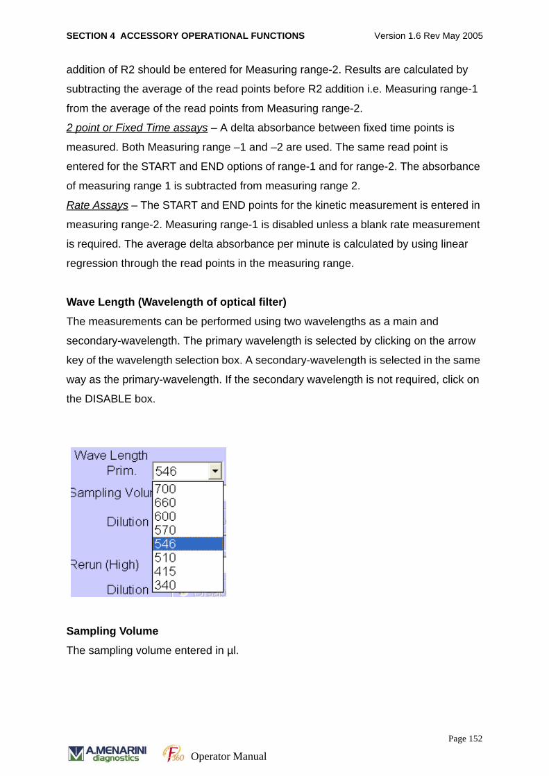
SECTION 4 ACCESSORY OPERATIONAL FUNCTIONS Version 1.6 Rev May 2005
addition of R2 should be entered for Measuring range-2. Results are calculated by
subtracting the average of the read points before R2 addition i.e. Measuring range-1
from the average of the read points from Measuring range-2.
2 point or Fixed Time assays – A delta absorbance between fixed time points is
measured. Both Measuring range –1 and –2 are used. The same read point is
entered for the START and END options of range-1 and for range-2. The absorbance
of measuring range 1 is subtracted from measuring range 2.
Rate Assays – The START and END points for the kinetic measurement is entered in
measuring range-2. Measuring range-1 is disabled unless a blank rate measurement
is required. The average delta absorbance per minute is calculated by using linear
regression through the read points in the measuring range.
Wave Length (Wavelength of optical filter)
The measurements can be performed using two wavelengths as a main and
secondary-wavelength. The primary wavelength is selected by clicking on the arrow
key of the wavelength selection box. A secondary-wavelength is selected in the same
way as the primary-wavelength. If the secondary wavelength is not required, click on
the DISABLE box.
Sampling Volume
The sampling volume entered in µl.
Page 152
Operator Manual
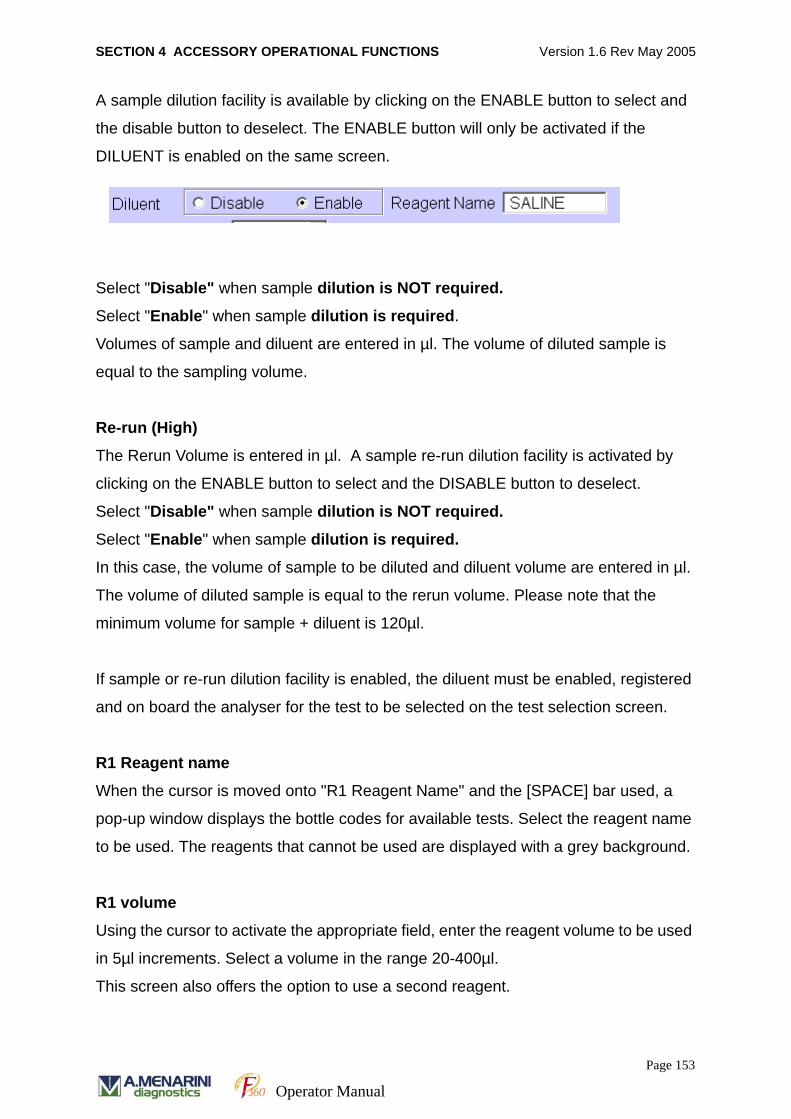
SECTION 4 ACCESSORY OPERATIONAL FUNCTIONS Version 1.6 Rev May 2005
A sample dilution facility is available by clicking on the ENABLE button to select and
the disable button to deselect. The ENABLE button will only be activated if the
DILUENT is enabled on the same screen.
Select "Disable" when sample dilution is NOT required.
Select "Enable" when sample dilution is required.
Volumes of sample and diluent are entered in µl. The volume of diluted sample is
equal to the sampling volume.
Re-run (High)
The Rerun Volume is entered in µl. A sample re-run dilution facility is activated by
clicking on the ENABLE button to select and the DISABLE button to deselect.
Select "Disable" when sample dilution is NOT required.
Select "Enable" when sample dilution is required.
In this case, the volume of sample to be diluted and diluent volume are entered in µl.
The volume of diluted sample is equal to the rerun volume. Please note that the
minimum volume for sample + diluent is 120µl.
If sample or re-run dilution facility is enabled, the diluent must be enabled, registered
and on board the analyser for the test to be selected on the test selection screen.
R1 Reagent name
When the cursor is moved onto "R1 Reagent Name" and the [SPACE] bar used, a
pop-up window displays the bottle codes for available tests. Select the reagent name
to be used. The reagents that cannot be used are displayed with a grey background.
R1 volume
Using the cursor to activate the appropriate field, enter the reagent volume to be used
in 5µl increments. Select a volume in the range 20-400µl.
This screen also offers the option to use a second reagent.
Page 153
Operator Manual
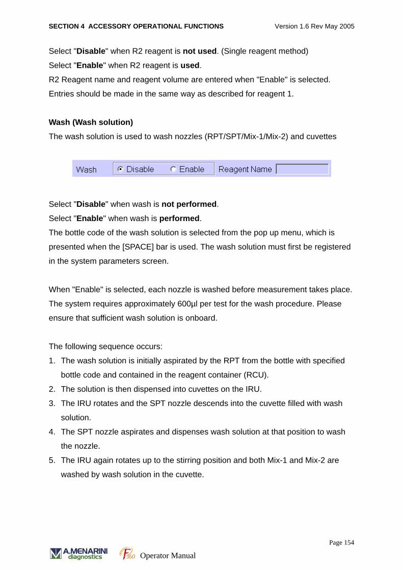
SECTION 4 ACCESSORY OPERATIONAL FUNCTIONS Version 1.6 Rev May 2005
Select "Disable" when R2 reagent is not used. (Single reagent method)
Select "Enable" when R2 reagent is used.
R2 Reagent name and reagent volume are entered when "Enable" is selected.
Entries should be made in the same way as described for reagent 1.
Wash (Wash solution)
The wash solution is used to wash nozzles (RPT/SPT/Mix-1/Mix-2) and cuvettes
Select "Disable" when wash is not performed.
Select "Enable" when wash is performed.
The bottle code of the wash solution is selected from the pop up menu, which is
presented when the [SPACE] bar is used. The wash solution must first be registered
in the system parameters screen.
When "Enable" is selected, each nozzle is washed before measurement takes place.
The system requires approximately 600µl per test for the wash procedure. Please
ensure that sufficient wash solution is onboard.
The following sequence occurs:
1. The wash solution is initially aspirated by the RPT from the bottle with specified
bottle code and contained in the reagent container (RCU).
2. The solution is then dispensed into cuvettes on the IRU.
3. The IRU rotates and the SPT nozzle descends into the cuvette filled with wash
solution.
4. The SPT nozzle aspirates and dispenses wash solution at that position to wash
the nozzle.
5. The IRU again rotates up to the stirring position and both Mix-1 and Mix-2 are
washed by wash solution in the cuvette.
Page 154
Operator Manual
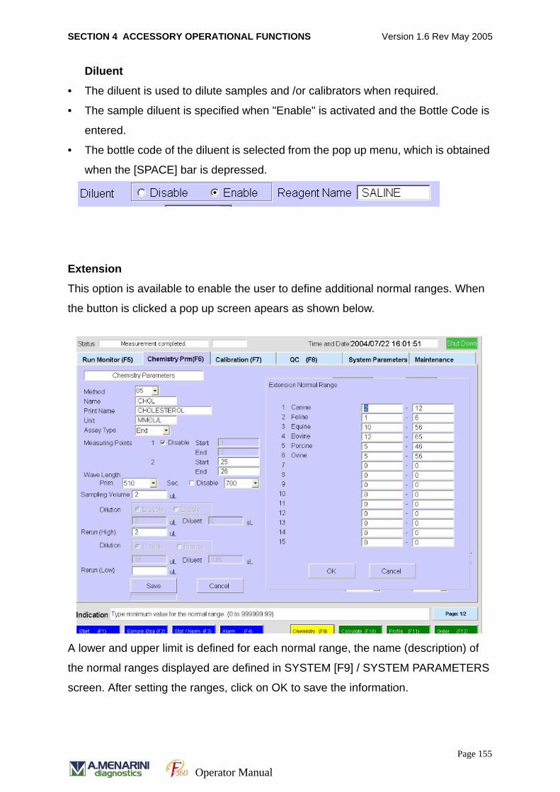
SECTION 4 ACCESSORY OPERATIONAL FUNCTIONS Version 1.6 Rev May 2005
Diluent
• The diluent is used to dilute samples and /or calibrators when required.
• The sample diluent is specified when "Enable" is activated and the Bottle Code is
entered.
• The bottle code of the diluent is selected from the pop up menu, which is obtained
when the [SPACE] bar is depressed.
Extension
This option is available to enable the user to define additional normal ranges. When
the button is clicked a pop up screen apears as shown below.
A lower and upper limit is defined for each normal range, the name (description) of
the normal ranges displayed are defined in SYSTEM [F9] / SYSTEM PARAMETERS
screen. After setting the ranges, click on OK to save the information.
Page 155
Operator Manual
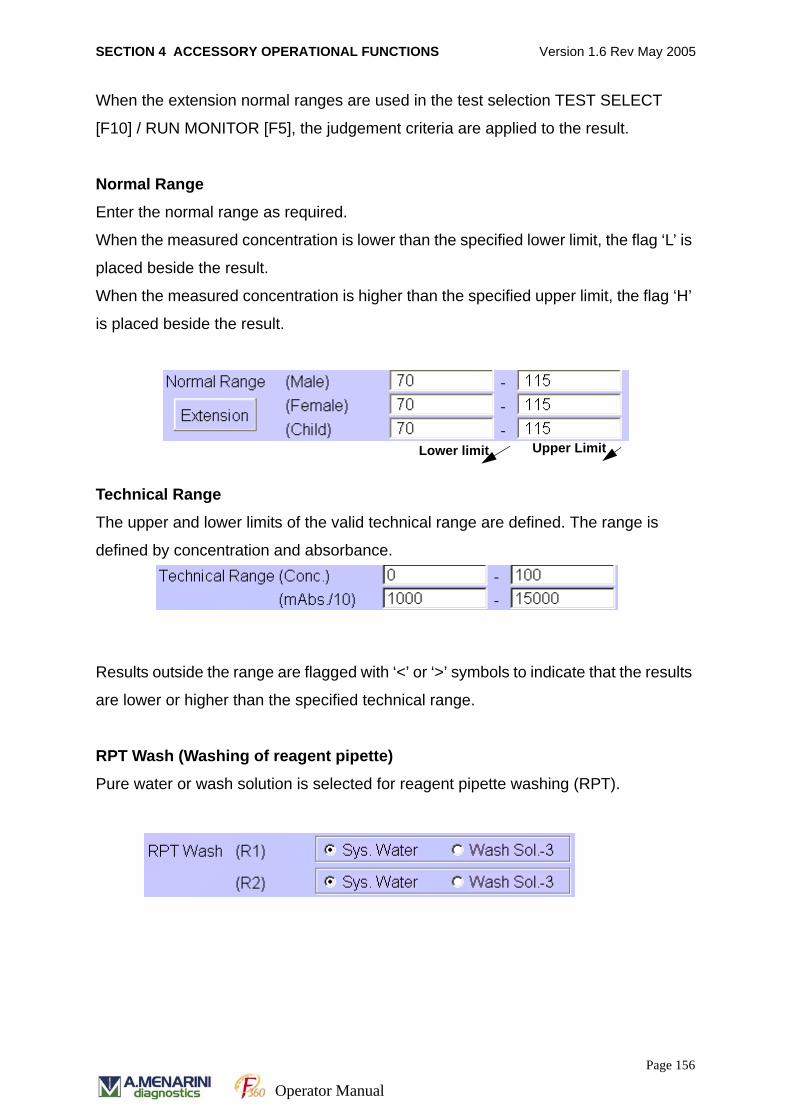
SECTION 4 ACCESSORY OPERATIONAL FUNCTIONS Version 1.6 Rev May 2005
When the extension normal ranges are used in the test selection TEST SELECT
[F10] / RUN MONITOR [F5], the judgement criteria are applied to the result.
Normal Range
Enter the normal range as required.
When the measured concentration is lower than the specified lower limit, the flag ‘L’ is
placed beside the result.
When the measured concentration is higher than the specified upper limit, the flag ‘H’
is placed beside the result.
Technical Range
The upper and lower limits of the valid technical range are defined. The range is
defined by concentration and absorbance.
Results outside the range are flagged with ‘<’ or ‘>’ symbols to indicate that the results
are lower or higher than the specified technical range.
RPT Wash (Washing of reagent pipette)
Pure water or wash solution is selected for reagent pipette washing (RPT).
Lower limit Upper Limit
Page 156
Operator Manual
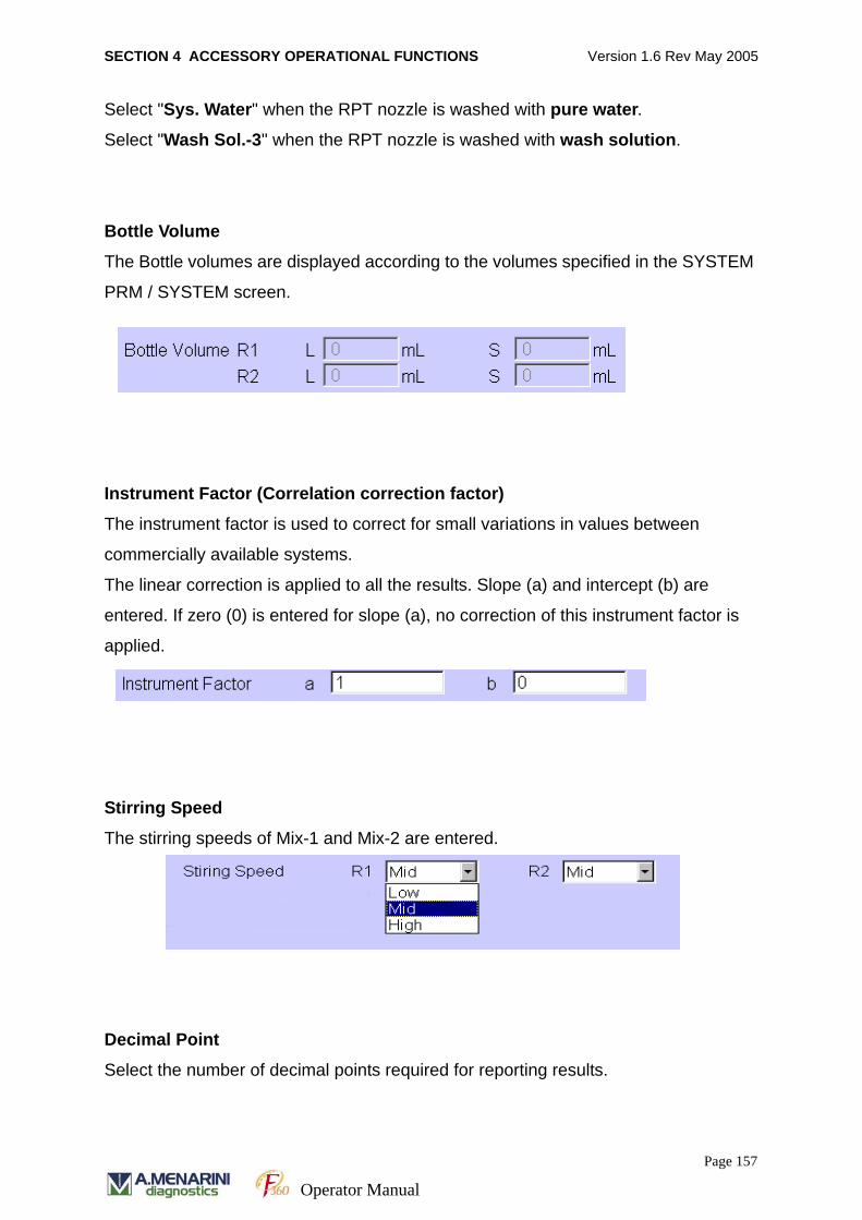
SECTION 4 ACCESSORY OPERATIONAL FUNCTIONS Version 1.6 Rev May 2005
Select "Sys. Water" when the RPT nozzle is washed with pure water.
Select "Wash Sol.-3" when the RPT nozzle is washed with wash solution.
Bottle Volume
The Bottle volumes are displayed according to the volumes specified in the SYSTEM
PRM / SYSTEM screen.
Instrument Factor (Correlation correction factor)
The instrument factor is used to correct for small variations in values between
commercially available systems.
The linear correction is applied to all the results. Slope (a) and intercept (b) are
entered. If zero (0) is entered for slope (a), no correction of this instrument factor is
applied.
Stirring Speed
The stirring speeds of Mix-1 and Mix-2 are entered.
Decimal Point
Select the number of decimal points required for reporting results.
Page 157
Operator Manual
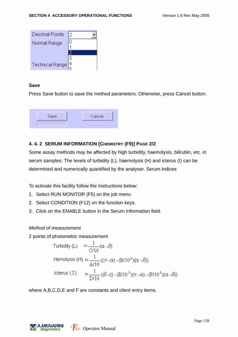
SECTION 4 ACCESSORY OPERATIONAL FUNCTIONS Version 1.6 Rev May 2005
Save
Press Save button to save the method parameters. Otherwise, press Cancel button.
4. 4. 2 SERUM INFORMATION [CHEMISTRY (F9)] PAGE 2/2
Some assay methods may be affected by high turbidity, haemolysis, bilirubin, etc. in
serum samples. The levels of turbidity (L), haemolysis (H) and icterus (I) can be
determined and numerically quantified by the analyser. Serum indices
To activate this facility follow the instructions below:
1. Select RUN MONITOR (F5) on the job menu
2. Select CONDITION (F12) on the function keys.
3. Click on the ENABLE button in the Serum Information field.
Method of measurement
2 points of photometric measurement
where A,B,C,D,E and F are constants and client entry items.
Page 158
Operator Manual

SECTION 4 ACCESSORY OPERATIONAL FUNCTIONS Version 1.6 Rev May 2005
= λ600, =λ700, = λ570, = λ415, = λ510
λxxx represents the absorbance values of each wavelength λrxxx which are obtained
from measurements of sample and phosphoric acid buffer and corrected by water
blank λwxxx. For example, in the case of wavelength of 600 nm,
λ600 = λ r600 - λ w600.
L = Turbidity Index
C = Scaling factor for Lipemia.
H = Hemolysis Index
A = Scaling factor for hemoglobin
B = Corrects hemoglobin measurement for lipemia.
I = Icterus index
D = Scaling factor for bilirubin
E = Corrects bilirubin measurement for for hemoglobin
B = Corrects hemoglobin measurement for lipemia
F = Corrects bilirubin measurement for lipemia.
Follow the instructions below to access the serum information screen.
1. Select CHEMISTRY PRM (F6) on the job menu
2. Select CHEMISTRY (F9) on the function keys.
3. Select Page 2 / 2 screen.
TurbidityNADH
Absorbance Icterus Hemolysis
340 415 450 510 570 600 700 800
Page 159
Operator Manual
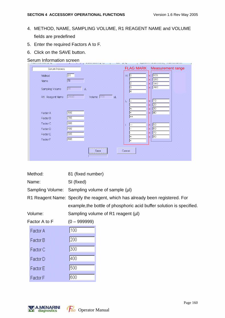
SECTION 4 ACCESSORY OPERATIONAL FUNCTIONS Version 1.6 Rev May 2005
4. METHOD, NAME, SAMPLING VOLUME, R1 REAGENT NAME and VOLUME
fields are predefined
5. Enter the required Factors A to F.
6. Click on the SAVE button.
Serum Information screen
Method: 81 (fixed number)
Name: SI (fixed)
Sampling Volume: Sampling volume of sample (µl)
R1 Reagent Name: Specify the reagent, which has already been registered. For
example,the bottle of phosphoric acid buffer solution is specified.
Volume: Sampling volume of R1 reagent (µl)
Factor A to F (0 – 999999)
FLAG MARK Measurement range
Page 160
Operator Manual
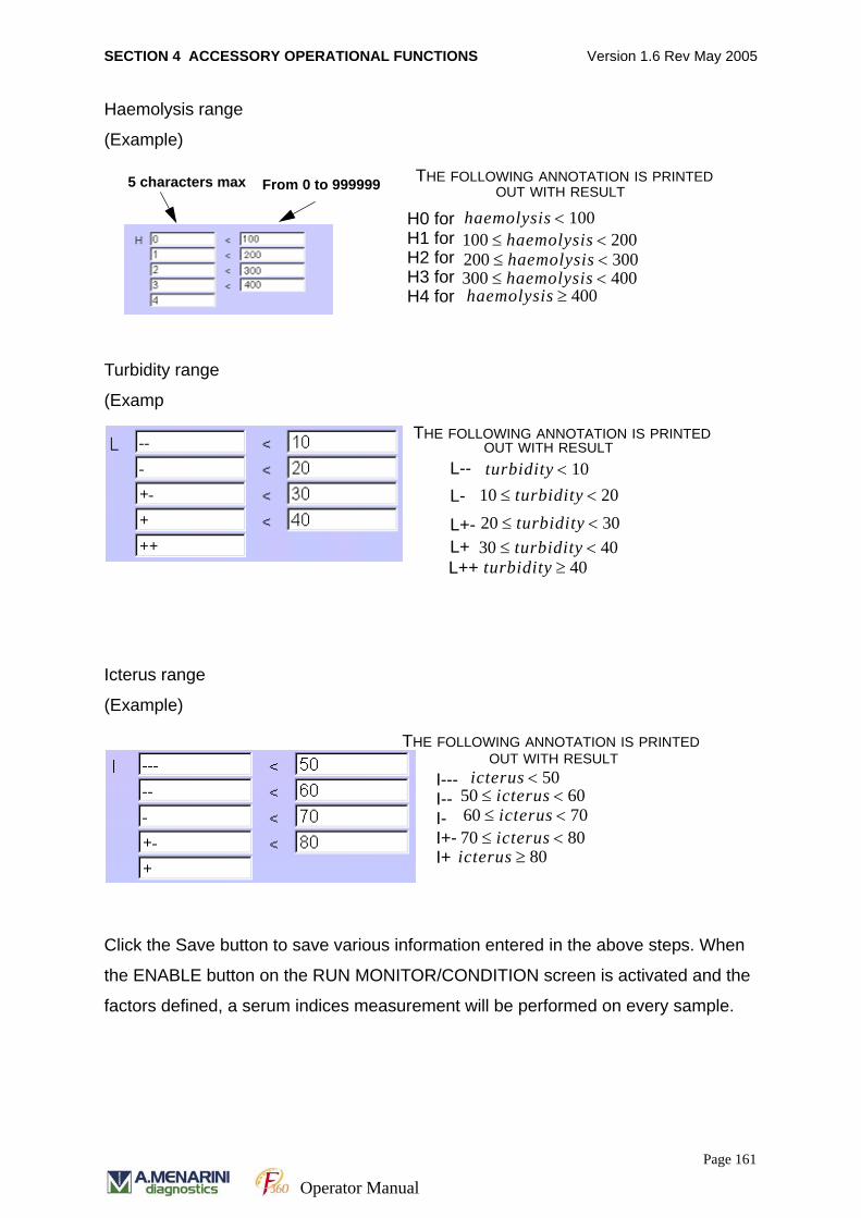
SECTION 4 ACCESSORY OPERATIONAL FUNCTIONS Version 1.6 Rev May 2005
Haemolysis range
(Example)
Turbidity range
(Examp
Icterus range
(Example)
Click the Save button to save various information entered in the above steps. When
the ENABLE button on the RUN MONITOR/CONDITION screen is activated and the
factors defined, a serum indices measurement will be performed on every sample.
5 characters max From 0 to 999999 THE FOLLOWING ANNOTATION IS PRINTED OUT WITH RESULT
H0 forH1 for H2 forH3 forH4 for
300 haemolysis 400<≤haemolysis 400≥
haemolysis 100<
200 haemolysis 300<≤100 haemolysis 200<≤
THE FOLLOWING ANNOTATION IS PRINTED OUT WITH RESULT
L--L-
L+-L+L++
turbidity 10<10 turbidity 20<≤
20 turbidity 30<≤30 turbidity 40<≤turbidity 40≥
THE FOLLOWING ANNOTATION IS PRINTED OUT WITH RESULT
icterus 50<
60 icterus 70<≤
icterus 80≥
50 icterus 60<≤
70 icterus 80<≤
I---I--I-I+-I+
Page 161
Operator Manual

SECTION 4 ACCESSORY OPERATIONAL FUNCTIONS Version 1.6 Rev May 2005
When a result is printed, the result of normal sample and ISE is printed with the serum
information. An example is shown below.
4. 4. 3 METHOD TO METHOD COMPUTATION
The software provides the facility to report a calculated value of test result(s) using a
defined equation.
For example total cholesterol (TC) and HDL cholesterol values may be requested as
a ratio of TC/HDL. Therefore the user can program the software to perform the
calculation automatically using this facility.
The software uses test method numbers 1 to 60 to identify individual test parameters.
Test method numbers 71 to 80 are assigned for calculation values.
1. Select CHEMISTRY PRM [F6] on job menu
2. Select CALCULATE [F10] on function keys. The screen appears as shown below.
3. Move cursor to the METHOD field and press SPACE bar to view method 71-80.
4. Select a method by clicking on the method required.
5. Move cursor to the NAME field and enter the required information.
6. Enter the units and the number of decimal places in the required fields.
7. Enter the calculation in the EXPRESSION field. The calculation equation can be
specified using symbols of four fundamental operations (+, –, x, / ) and braces { }.
Square brackets are used to enclose method number. The method number may
be selected by clicking on the required method in the list or typed directly into the
field.
Sno. : 101 ID:2001082701 Date : 20020827 RoundNo : 006 UREA AST 15.1 20.5 SI H3 ( 358) L+- ( 32) I-- ( 68)
Method Name Result of Hemolysis Result of Turbidity Result of Icterus
Normalsample result
Page 162
Operator Manual
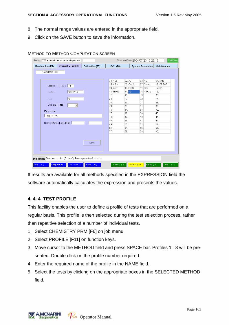
SECTION 4 ACCESSORY OPERATIONAL FUNCTIONS Version 1.6 Rev May 2005
8. The normal range values are entered in the appropriate field.
9. Click on the SAVE button to save the information.
METHOD TO METHOD COMPUTATION SCREEN
If results are available for all methods specified in the EXPRESSION field the
software automatically calculates the expression and presents the values.
4. 4. 4 TEST PROFILE
This facility enables the user to define a profile of tests that are performed on a
regular basis. This profile is then selected during the test selection process, rather
than repetitive selection of a number of individual tests.
1. Select CHEMISTRY PRM [F6] on job menu
2. Select PROFILE [F11] on function keys.
3. Move cursor to the METHOD field and press SPACE bar. Profiles 1 –8 will be pre-
sented. Double click on the profile number required.
4. Enter the required name of the profile in the NAME field.
5. Select the tests by clicking on the appropriate boxes in the SELECTED METHOD
field.
Page 163
Operator Manual
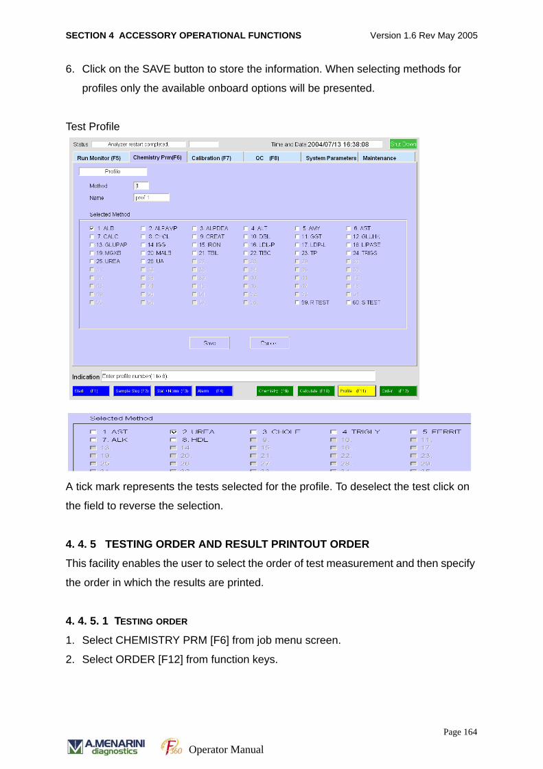
SECTION 4 ACCESSORY OPERATIONAL FUNCTIONS Version 1.6 Rev May 2005
6. Click on the SAVE button to store the information. When selecting methods for
profiles only the available onboard options will be presented.
Test Profile
A tick mark represents the tests selected for the profile. To deselect the test click on
the field to reverse the selection.
4. 4. 5 TESTING ORDER AND RESULT PRINTOUT ORDER
This facility enables the user to select the order of test measurement and then specify
the order in which the results are printed.
4. 4. 5. 1 TESTING ORDER
1. Select CHEMISTRY PRM [F6] from job menu screen.
2. Select ORDER [F12] from function keys.
Page 164
Operator Manual
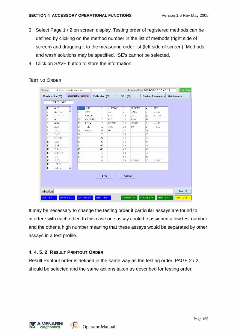
SECTION 4 ACCESSORY OPERATIONAL FUNCTIONS Version 1.6 Rev May 2005
3. Select Page 1 / 2 on screen display. Testing order of registered methods can be
defined by clicking on the method number in the list of methods (right side of
screen) and dragging it to the measuring order list (left side of screen). Methods
and wash solutions may be specified. ISE’s cannot be selected.
4. Click on SAVE button to store the information.
TESTING ORDER
It may be necessary to change the testing order if particular assays are found to
interfere with each other. In this case one assay could be assigned a low test number
and the other a high number meaning that these assays would be separated by other
assays in a test profile.
4. 4. 5. 2 RESULT PRINTOUT ORDER
Result Printout order is defined in the same way as the testing order. PAGE 2 / 2
should be selected and the same actions taken as described for testing order.
TESTING ORDER LIST
Page 165
Operator Manual

SECTION 4 ACCESSORY OPERATIONAL FUNCTIONS Version 1.6 Rev May 2005
PRINT ORDER SCREEN
4. 4. 6 ENTRY OF SYSTEM PARAMETERS
This facility enables the user to define the system parameters, registration of open
channel reagents, operation of floppy disk, and retrieval of results.
1. Select SYSTEM PRM [F6] on job menu
2. Select SYSTEM [F9] on the function keys. The system parameters are displayed
on screen as shown below.
3. Move the cursor to the field of interest and use the scroll arrow to view the list for
selection.
Page 166
Operator Manual

SECTION 4 ACCESSORY OPERATIONAL FUNCTIONS Version 1.6 Rev May 2005
SYSTEM PARAMETERS
Host Communication
The conditions for communication with the host computer are defined as follows.
Details
This is an optional settings button for setting the output of data to either Host
Communications, Floppy Disc or Printout.
Click on the DETAILS button and the following screen will appear.
Item Description Remarks
Baud
Rate
Selection of baud rate: 19200/9600/
4800 bps
Default: 9600 bps
Data Bit Data bit length: 7/8 bits Default: 8 bits
Stop Bit Stop bit length: 1/2 bits Default: 2 bits
Parity Bit Parity bit: None/Even/Odd Default: None
Page 167
Operator Manual
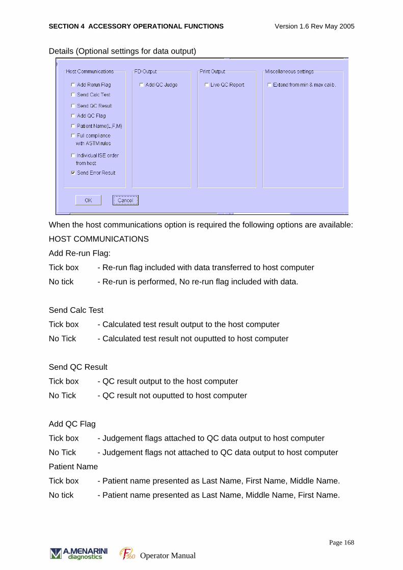
SECTION 4 ACCESSORY OPERATIONAL FUNCTIONS Version 1.6 Rev May 2005
Details (Optional settings for data output)
When the host communications option is required the following options are available:
HOST COMMUNICATIONS
Add Re-run Flag:
Tick box - Re-run flag included with data transferred to host computer
No tick - Re-run is performed, No re-run flag included with data.
Send Calc Test
Tick box - Calculated test result output to the host computer
No Tick - Calculated test result not ouputted to host computer
Send QC Result
Tick box - QC result output to the host computer
No Tick - QC result not ouputted to host computer
Add QC Flag
Tick box - Judgement flags attached to QC data output to host computer
No Tick - Judgement flags not attached to QC data output to host computer
Patient Name
Tick box - Patient name presented as Last Name, First Name, Middle Name.
No tick - Patient name presented as Last Name, Middle Name, First Name.
Page 168
Operator Manual
SECTION 4 ACCESSORY OPERATIONAL FUNCTIONS Version 1.6 Rev May 2005
Full compliance with ASTM rules
Tick box - Online communication compatible with ASTM rules.
No tick - Online communication is not fully compatible with ASTM rules. Please
refer to the Host Interface Software Specification document for further details. This
information is available from your local A. MENARINI Diagnostics representative.
Individual ISE order from host
Tick box - Testing order of ISE is on individual test basis e.g. No 61-Na, No 62-K,
No. 63-Cl, No64-Na (Diluted), No. 65-K (Diluted), No. 66-Cl(diluted).
No tick - Testing order of ISE is in standard form e.g. No 61-Na, K, Cl,
No 62-Na, K, Cl (DIluted).
Send error result
Tick box - Send error flag results to host
No tick - Do not send error flag results to host.
FD OUTPUT
Tick the box to attach the judgement condition flag to the QC results when transferred
to Floppy Disc and untick the box to detach the judgement flag to QC results
transferred to floppy disc.
PRINT OUTPUT
Tick the box to print the QC report in real time and untick the box to disable this
function. The QC data printout is available after measurement.
MISCELLANEOUS SETTINGS (EXTEND FROM MIN & MAX CALIBRATION)
Tick box - Min or Max point of calibration curve applied to result as a
concentration value.
No tick - Measurement result is calculated from an extended calibration curve
as a concentration value.
Page 169
Operator Manual
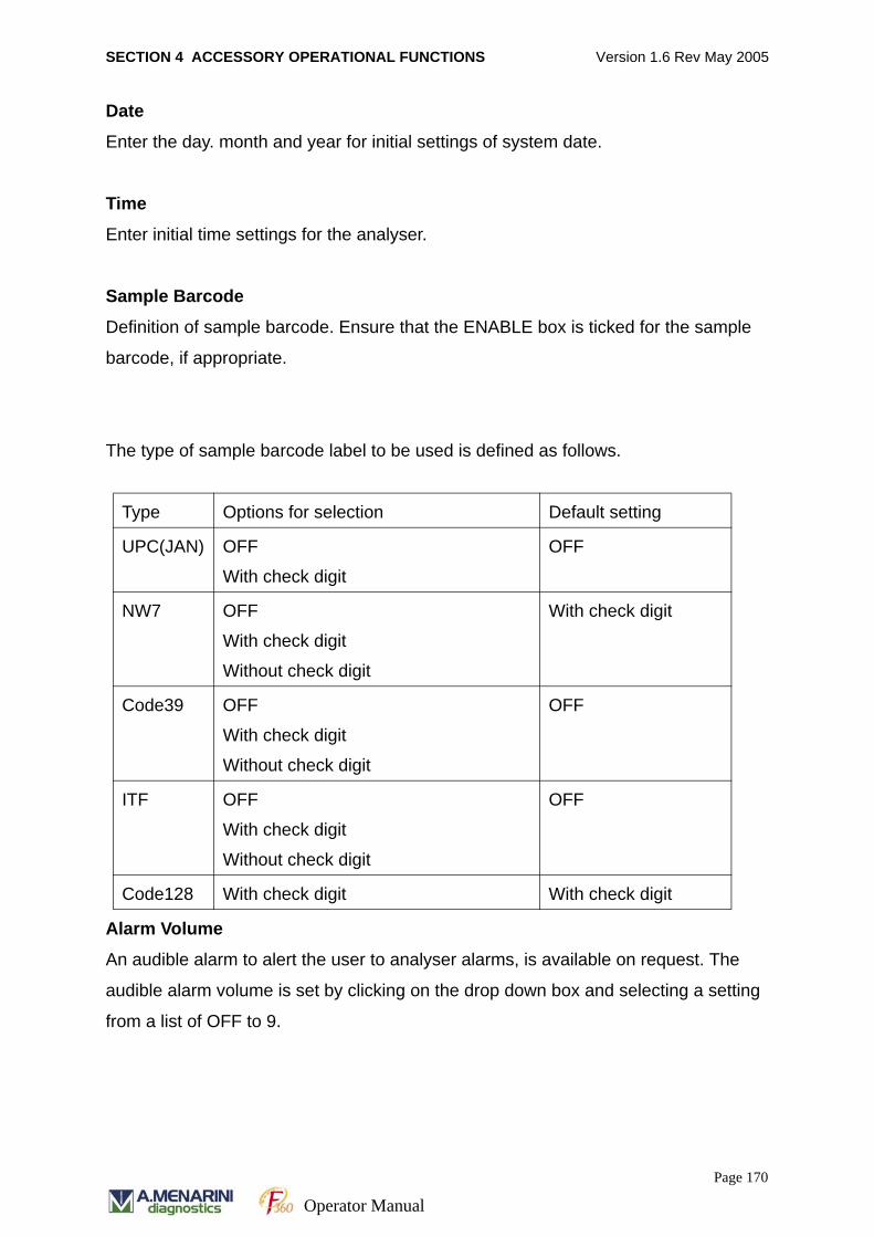
SECTION 4 ACCESSORY OPERATIONAL FUNCTIONS Version 1.6 Rev May 2005
Date
Enter the day. month and year for initial settings of system date.
Time
Enter initial time settings for the analyser.
Sample Barcode
Definition of sample barcode. Ensure that the ENABLE box is ticked for the sample
barcode, if appropriate.
The type of sample barcode label to be used is defined as follows.
Alarm Volume
An audible alarm to alert the user to analyser alarms, is available on request. The
audible alarm volume is set by clicking on the drop down box and selecting a setting
from a list of OFF to 9.
Type Options for selection Default setting
UPC(JAN) OFF
With check digit
OFF
NW7 OFF
With check digit
Without check digit
With check digit
Code39 OFF
With check digit
Without check digit
OFF
ITF OFF
With check digit
Without check digit
OFF
Code128 With check digit With check digit
Page 170
Operator Manual
SECTION 4 ACCESSORY OPERATIONAL FUNCTIONS Version 1.6 Rev May 2005
Alarm Setting
Options for alarm activation are available to the user.Click on the Alarm Setting button
to view the five alarm options. One or more options may be selected. Details are
listed below:
Alarm 1 Emergency Stop has been initiated
Alarm 2 Sampling Stop has been initiated
Alarm 3 Warning has been activated
Alarm 4 Error has occurred in the PC
Alarm 5 Error has occurred when ASP rotation is completed.
Click on the alarm option required and a Tick will appear in the associated box. Click
again to de-activate the alarm.
Printout header
Printout headers for hard copy reports. There are two header options:
1. Universal header – applied to all printed material. Click on the ‘Printout header’
field and enter the required header information directly.
2. Definitive header – defines specific headers for patient reports only. Click on the
‘Define header’ box and then enter the required information on the appropriate
field.
Sample Number Increment
Click on this option to define the method of sample number increment. Three choices
available as follows:
Numeric only Addition of 2 digits e.g. 01-99
Alphanumeric (Upper case) Addition of 2 digits e.g. 01-09, 0A-0Z, 10-99, 9A-ZZ
Alphanumeric (lower case) Addition of 2 digits e.g. 01-09, 0A-0Z, 10-99, 9A-ZZ,
Za-zz.
Program version
Details the program version number currently in use.
Page 171
Operator Manual
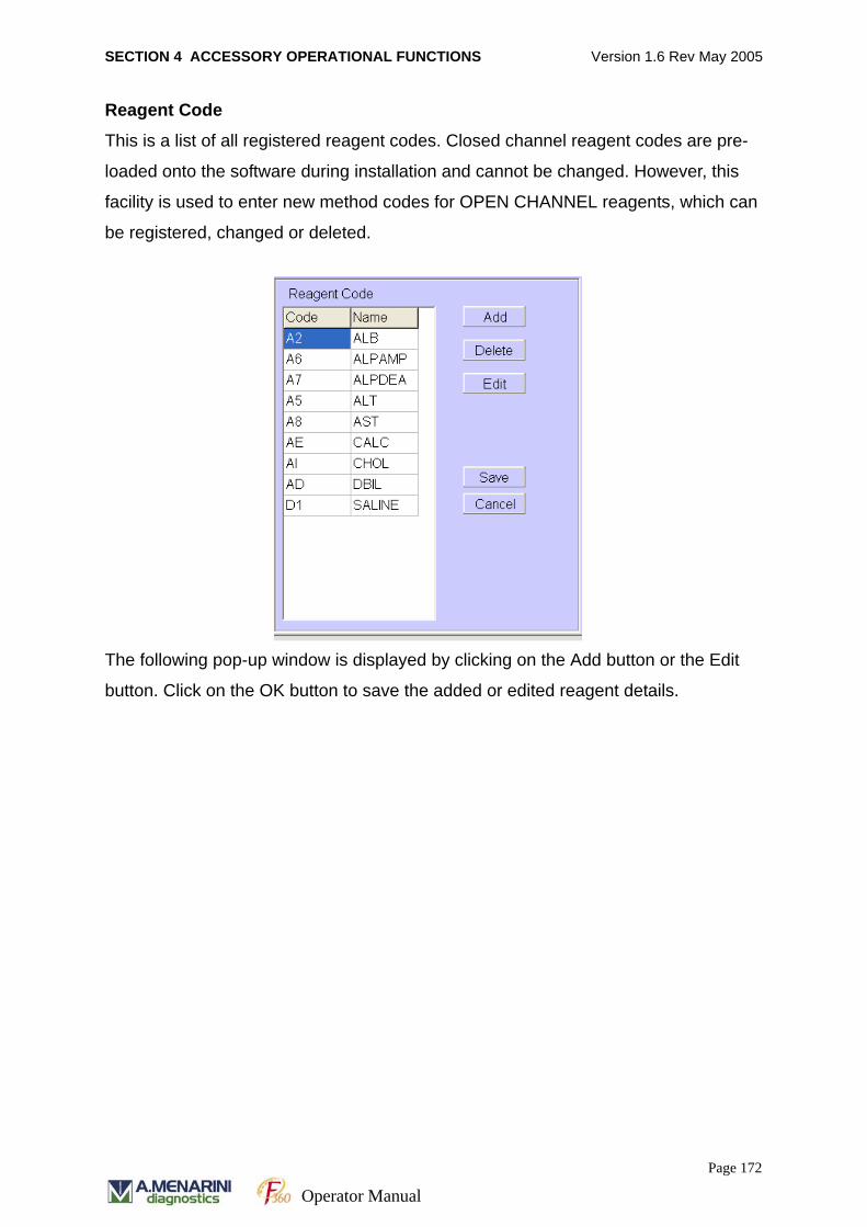
SECTION 4 ACCESSORY OPERATIONAL FUNCTIONS Version 1.6 Rev May 2005
Reagent Code
This is a list of all registered reagent codes. Closed channel reagent codes are pre-
loaded onto the software during installation and cannot be changed. However, this
facility is used to enter new method codes for OPEN CHANNEL reagents, which can
be registered, changed or deleted.
The following pop-up window is displayed by clicking on the Add button or the Edit
button. Click on the OK button to save the added or edited reagent details.
Page 172
Operator Manual
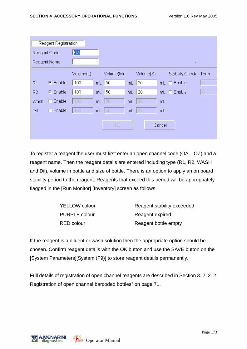
SECTION 4 ACCESSORY OPERATIONAL FUNCTIONS Version 1.6 Rev May 2005
To register a reagent the user must first enter an open channel code (OA – OZ) and a
reagent name. Then the reagent details are entered including type (R1, R2, WASH
and Dil), volume in bottle and size of bottle. There is an option to apply an on board
stability period to the reagent. Reagents that exceed this period will be appropriately
flagged in the [Run Monitor] [Inventory] screen as follows:
YELLOW colour Reagent stability exceeded
PURPLE colour Reagent expired
RED colour Reagent bottle empty
If the reagent is a diluent or wash solution then the appropriate option should be
chosen. Confirm reagent details with the OK button and use the SAVE button on the
[System Parameters][System (F9)] to store reagent details permanently.
Full details of registration of open channel reagents are described in Section 3. 2. 2. 2
Registration of open channel barcoded bottles” on page 71.
Page 173
Operator Manual
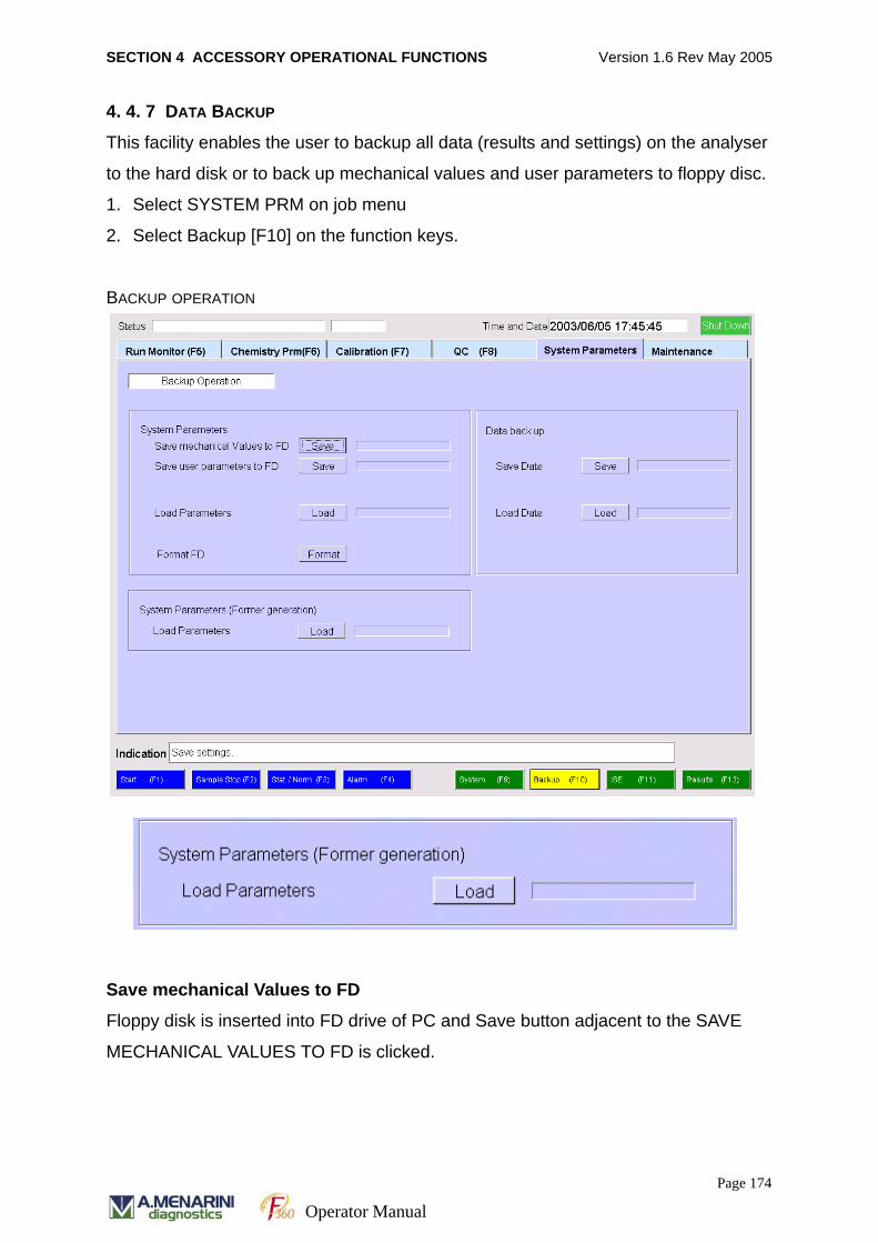
SECTION 4 ACCESSORY OPERATIONAL FUNCTIONS Version 1.6 Rev May 2005
4. 4. 7 DATA BACKUP
This facility enables the user to backup all data (results and settings) on the analyser
to the hard disk or to back up mechanical values and user parameters to floppy disc.
1. Select SYSTEM PRM on job menu
2. Select Backup [F10] on the function keys.
BACKUP OPERATION
Save mechanical Values to FD
Floppy disk is inserted into FD drive of PC and Save button adjacent to the SAVE
MECHANICAL VALUES TO FD is clicked.
Page 174
Operator Manual
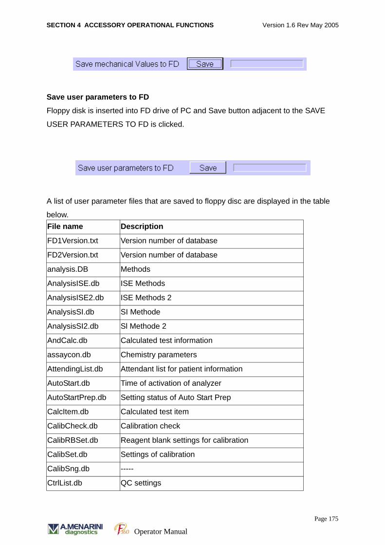
SECTION 4 ACCESSORY OPERATIONAL FUNCTIONS Version 1.6 Rev May 2005
Save user parameters to FD
Floppy disk is inserted into FD drive of PC and Save button adjacent to the SAVE
USER PARAMETERS TO FD is clicked.
A list of user parameter files that are saved to floppy disc are displayed in the table
below.File name Description
FD1Version.txt Version number of database
FD2Version.txt Version number of database
analysis.DB Methods
AnalysisISE.db ISE Methods
AnalysisISE2.db ISE Methods 2
AnalysisSI.db SI Methode
AnalysisSI2.db Sl Methode 2
AndCalc.db Calculated test information
assaycon.db Chemistry parameters
AttendingList.db Attendant list for patient information
AutoStart.db Time of activation of analyzer
AutoStartPrep.db Setting status of Auto Start Prep
CalcItem.db Calculated test item
CalibCheck.db Calibration check
CalibRBSet.db Reagent blank settings for calibration
CalibSet.db Settings of calibration
CalibSng.db -----
CtrlList.db QC settings
Page 175
Operator Manual
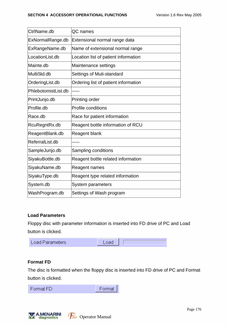
SECTION 4 ACCESSORY OPERATIONAL FUNCTIONS Version 1.6 Rev May 2005
Load Parameters
Floppy disc with parameter information is inserted into FD drive of PC and Load
button is clicked.
Format FD
The disc is formatted when the floppy disc is inserted into FD drive of PC and Format
button is clicked.
CtrlName.db QC names
ExNormalRange.db Extensional normal range data
ExRangeName.db Name of extensional normal range
LocationList.db Location list of patient information
Mainte.db Maintenance settings
MultiStd.db Settings of Muti-standard
OrderingList.db Ordering list of patient information
PhlebotomistList.db -----
PrintJunjo.db Printing order
Profile.db Profile conditions
Race.db Race for patient information
RcuRegntRx.db Reagent bottle information of RCU
ReagentBlank.db Reagent blank
ReferralList.db -----
SampleJunjo.db Sampling conditions
SiyakuBottle.db Reagent bottle related information
SiyakuName.db Reagent names
SiyakuType.db Reagent type related information
System.db System parameters
WashProgram.db Settings of Wash program
Page 176
Operator Manual
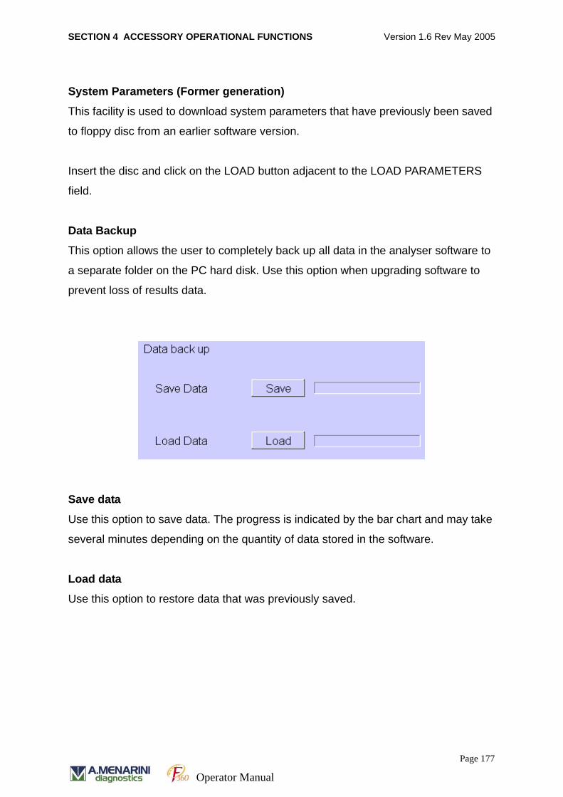
SECTION 4 ACCESSORY OPERATIONAL FUNCTIONS Version 1.6 Rev May 2005
System Parameters (Former generation)
This facility is used to download system parameters that have previously been saved
to floppy disc from an earlier software version.
Insert the disc and click on the LOAD button adjacent to the LOAD PARAMETERS
field.
Data Backup
This option allows the user to completely back up all data in the analyser software to
a separate folder on the PC hard disk. Use this option when upgrading software to
prevent loss of results data.
Save data
Use this option to save data. The progress is indicated by the bar chart and may take
several minutes depending on the quantity of data stored in the software.
Load data
Use this option to restore data that was previously saved.
Page 177
Operator Manual
SECTION 4 ACCESSORY OPERATIONAL FUNCTIONS Version 1.6 Rev May 2005
4. 4. 8 TEST SELECTION WHEN CONNECTED TO HOST COMPUTER
The software offers the facility to download test method selections for individual
patient samples directly from a host computer system. Patient Demographic
information for each sample may be transferred to the analyser PC if desired.
Data download is carried out in on-line batch or on-line real time mode.
1. Online Batch Mode 1 – the analyser is connected to the host and sample informa-
tion is ordered in batches. The results are automatically sent to the host computer
when they become available.
2. Online Batch Mode 2 - the analyser is connected to the host and sample informa-
tion is ordered in batches. The results are NOT automatically sent to the host com-
puter when they become available. The software requires user validation of
results and transfer of the data to the host computer.
3. Online Real Time Mode (Host Query Mode) – the analyser is in constant commu-
nication with the host computer. Sample information is requested for each sample
when the analyser reads the barcode. Results are automatically transferred back
to the host computer as they become available.
4. 4. 8. 1 TEST SELECTION FOR SAMPLE IN ON-LINE BATCH MODE 1 AND 2
Using on-line batch mode 1 or 2, test selection information for all samples is
transferred to the analyser PC before measurement is initiated.
1. Check on [System Parameters][System (F9)] screen and ensure the ‘Sample Bar-
code’ mode is set to ‘Enable’.
2. Select RUN MONITOR [F5] on job menu
3. Select CONDITION [F12] on function keys.
4. Move the cursor to the desired function within the HOST COMMUNICATION
MODE box.
5. Select by clicking on ON LINE BATCH 1 or 2 button. A pop up screen will appear
notifying the user to restart the computer.
6. After re-starting the computer the analyser software will now be in batch mode and
ready for information transfer.
7. Load barcoded samples onto the sample carousel.
Page 178
Operator Manual
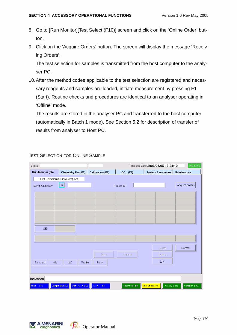
SECTION 4 ACCESSORY OPERATIONAL FUNCTIONS Version 1.6 Rev May 2005
8. Go to [Run Monitor][Test Select (F10)] screen and click on the ‘Online Order’ but-
ton.
9. Click on the ‘Acquire Orders’ button. The screen will display the message ‘Receiv-
ing Orders’.
The test selection for samples is transmitted from the host computer to the analy-
ser PC.
10.After the method codes applicable to the test selection are registered and neces-
sary reagents and samples are loaded, initiate measurement by pressing F1
(Start). Routine checks and procedures are identical to an analyser operating in
‘Offline’ mode.
The results are stored in the analyser PC and transferred to the host computer
(automatically in Batch 1 mode). See Section 5.2 for description of transfer of
results from analyser to Host PC.
TEST SELECTION FOR ONLINE SAMPLE
Page 179
Operator Manual
SECTION 4 ACCESSORY OPERATIONAL FUNCTIONS Version 1.6 Rev May 2005
4. 4. 8. 2 CONFIRMATION OF TEST SELECTION
The information of test selection sent from the host computer can be confirmed on the
screen of the main unit prior to measurement. Use the ‘List’ button to display all the
requested tests for each sample as follows.
1. Click on the LIST option. A list of all test selections is displayed on screen.
Selected tests are displayed in blue and non-selected tests displayed in black and
tests not available for selection are displayed in grey.
2. To select / deselect a test simply move the cursor to the test of interest and press
the SPACE bar.
3. Use the JUMP option to quickly find the defined sample number in a large list.
4. Click on the CLOSE button to save the changes.
4. 4. 8. 3 TEST SELECTION FOR SAMPLE IN ON-LINE REAL TIME MODE
The on-line real time mode function raises method codes for samples by sending a
query to the host computer when the sample bar code is read.
1. Select RUN MONITOR [F5] on job menu.
2. Select CONDITION [F12] on function keys.
3. Move the cursor to the desired function within the HOST COMMUNICATION
MODE box.
4. Select by clicking ON REAL TIME button. After the method codes are registered
and necessary reagents and samples are loaded, the measurement is initiated.
The analyser reads the bar code of sample and raises a query for the method
codes to the host computer, and then initiates measurement. This sequence is
repeated for each sample.
The measurement results are stored in the analyser PC and transferred to the
host computer in real time as well.
4. 4. 8. 4 CAUTIONS IN USING ON-LINE REAL TIME MODE
Test selection transferred to the analyser PC from a host computer in on-line real time
mode cannot be viewed in the analyser software.
Test selection can be made in the analyser software only for emergency samples.
Page 180
Operator Manual
SECTION 4 ACCESSORY OPERATIONAL FUNCTIONS Version 1.6 Rev May 2005
4. 4. 8. 5 SWITCH OFF HOST COMMUNICATION MODE
The host communication mode may be switched off when not required.
1. Select RUN MONITOR [F5] on job menu
2. Select CONDITION [F12] on function keys.
3. Move the cursor to the desired function within the HOST COMMUNICATION
MODE box.
4. Select by clicking OFF LINE.
4. 4. 9 INPUT OF PATIENT INFORMATION DETAILS
Each sample may be assigned a unique Patient ID number (Up to 13 alphanumeric
characters) that associates the sample with patient demographic information. Patient
ID numbers may either be predefined or entered at the time of test selection.
4. 4. 9. 1 INPUT OF PATENT ID NUMBER
Predefined Patient ID numbers are set up as follows.
1. Select SYSTEM PARAMETERS on job menu.
2. Select SYSTEM [F9] on function keys.
3. Click on the page number and go to Page 2/2 option.
4. Click on the Patient Information button. Enter the appropriate information in the
required field to complete the patient details. These include Patient ID number,
Patient Name (Last, First and Middle), Social Security number, Date of birth
(Month, Day, Year), Age (automatically calculated from Date of birth), Sex and
Race.
5. Click on the SAVE button to store the information. The software can store a maxi-
mum of 9999 patient information records. Patient records should be kept up to
date with the deletion of unnecessary records.
Page 181
Operator Manual
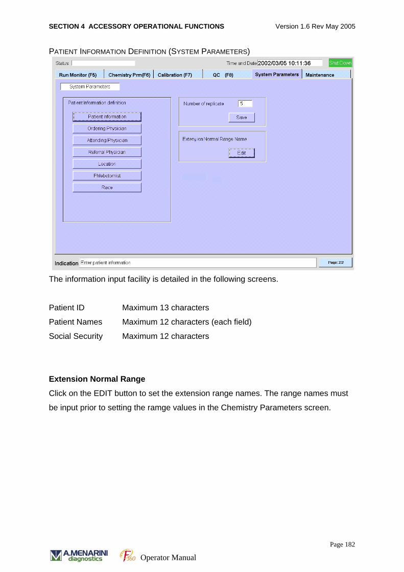
SECTION 4 ACCESSORY OPERATIONAL FUNCTIONS Version 1.6 Rev May 2005
PATIENT INFORMATION DEFINITION (SYSTEM PARAMETERS)
The information input facility is detailed in the following screens.
Patient ID Maximum 13 characters
Patient Names Maximum 12 characters (each field)
Social Security Maximum 12 characters
Extension Normal Range
Click on the EDIT button to set the extension range names. The range names must
be input prior to setting the ramge values in the Chemistry Parameters screen.
Page 182
Operator Manual
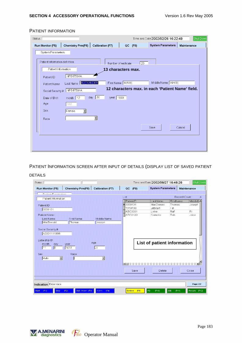
SECTION 4 ACCESSORY OPERATIONAL FUNCTIONS Version 1.6 Rev May 2005
PATIENT INFORMATION
PATIENT INFORMATION SCREEN AFTER INPUT OF DETAILS (DISPLAY LIST OF SAVED PATIENT
DETAILS
13 characters max.
12 characters max. in each ‘Patient Name’ field.
List of patient information
Page 183
Operator Manual

SECTION 4 ACCESSORY OPERATIONAL FUNCTIONS Version 1.6 Rev May 2005
4. 4. 9. 2 INPUT OF ORDERING PHYSICIAN, ATTENDING PHYSICIAN AND REFERRAL
PHYSICIAN DETAILS
The software offers the facility to input and store information on Ordering Physician,
Attending Physician and Referral Physician.
1. Select SYSTEM PARAMETERS on job menu.
2. Select SYSTEM [F9] on function keys.
3. Click on the page number and go to Page 2/2 option.
4. Click on the button required i.e.: Ordering Physician, Attending Physician or Refer-
ral Physician. Enter the appropriate information (Maximum 32 characters) in the
required field.
5. Click on the ADD button and enter the physician name in the NAME field.
6. Click on SAVE and the software will automatically add the new details to the list.
7. Click on CLOSE to exit the screen.
ORDERING PHYSICIAN DETAILS
Page 184
Operator Manual
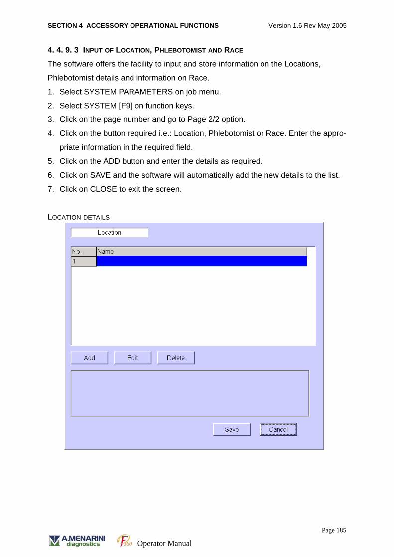
SECTION 4 ACCESSORY OPERATIONAL FUNCTIONS Version 1.6 Rev May 2005
4. 4. 9. 3 INPUT OF LOCATION, PHLEBOTOMIST AND RACE
The software offers the facility to input and store information on the Locations,
Phlebotomist details and information on Race.
1. Select SYSTEM PARAMETERS on job menu.
2. Select SYSTEM [F9] on function keys.
3. Click on the page number and go to Page 2/2 option.
4. Click on the button required i.e.: Location, Phlebotomist or Race. Enter the appro-
priate information in the required field.
5. Click on the ADD button and enter the details as required.
6. Click on SAVE and the software will automatically add the new details to the list.
7. Click on CLOSE to exit the screen.
LOCATION DETAILS
Page 185
Operator Manual
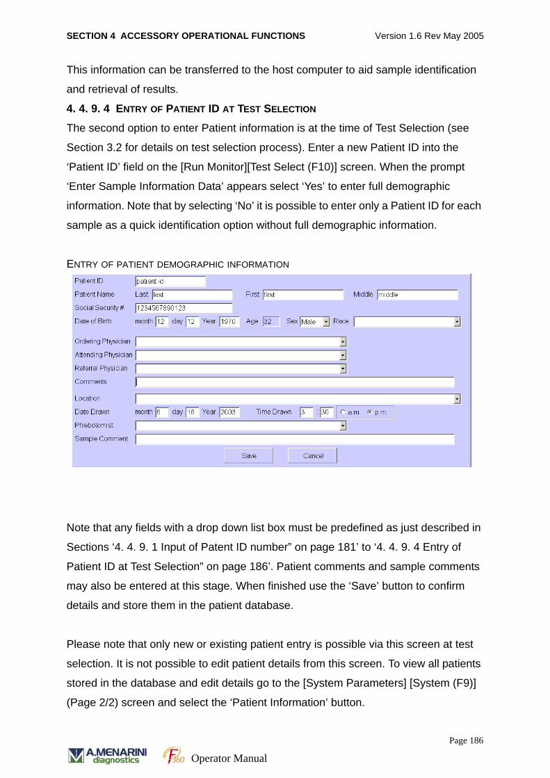
SECTION 4 ACCESSORY OPERATIONAL FUNCTIONS Version 1.6 Rev May 2005
This information can be transferred to the host computer to aid sample identification
and retrieval of results.
4. 4. 9. 4 ENTRY OF PATIENT ID AT TEST SELECTION
The second option to enter Patient information is at the time of Test Selection (see
Section 3.2 for details on test selection process). Enter a new Patient ID into the
‘Patient ID’ field on the [Run Monitor][Test Select (F10)] screen. When the prompt
‘Enter Sample Information Data’ appears select ‘Yes’ to enter full demographic
information. Note that by selecting ‘No’ it is possible to enter only a Patient ID for each
sample as a quick identification option without full demographic information.
ENTRY OF PATIENT DEMOGRAPHIC INFORMATION
Note that any fields with a drop down list box must be predefined as just described in
Sections ‘4. 4. 9. 1 Input of Patent ID number” on page 181’ to ‘4. 4. 9. 4 Entry of
Patient ID at Test Selection” on page 186’. Patient comments and sample comments
may also be entered at this stage. When finished use the ‘Save’ button to confirm
details and store them in the patient database.
Please note that only new or existing patient entry is possible via this screen at test
selection. It is not possible to edit patient details from this screen. To view all patients
stored in the database and edit details go to the [System Parameters] [System (F9)]
(Page 2/2) screen and select the ‘Patient Information’ button.
Page 186
Operator Manual
SECTION 5 RETRIEVAL OF RESULTS Version 1.6 Rev May 2005
SECTION 5
RETRIEVAL OF RESULTS
Page 187Operator Manual
SECTION 5 RETRIEVAL OF RESULTS Version 1.6 Rev May 2005
5.1 AUTOMATIC PRINTOUT OF RESULTSThe software offers two options for printout and retrieval of patient results.
• Automatic Printout
• Retrieval of stored results
The software offers an option to automatically print out hard copies of patient results
when they become available.
The facility offers two options:
• To print the results list when the sample run is complete.
• To print results in the form of a patient report which would include all the patient
details and test results required.
The automatic printout facility is activated according to the instructions below.
1. Select RUN MONITOR (F5) on the job menu.
2. Select CONDITION (F12) on the function keys.
3. In the AUTOMATIC PRINTOUT field select one of the three options by clicking on
the one of interest.
Patient – Print results in the form of a patient report
Result – Print result list only
Disable – To inactivate the automatic printout function.
Page 188Operator Manual
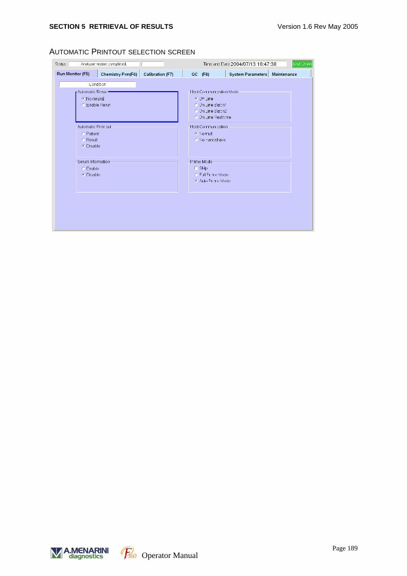
SECTION 5 RETRIEVAL OF RESULTS Version 1.6 Rev May 2005
AUTOMATIC PRINTOUT SELECTION SCREEN
Page 189Operator Manual
SECTION 5 RETRIEVAL OF RESULTS Version 1.6 Rev May 2005
5.2 RETRIEVAL OF STORED RESULTSAll results can be accessed in the SYSTEM PARAMETERS / RESULTS (F12) screen.
1. Select SYSTEM PARAMETERS on job menu.
2. Select RESULTS [F12] on function keys. The results screen will be displayed as
shown below. This screen enables the user to search for results on the basis of
sample type, sample number, date of analysis and Round number. Enter an * in
fields, except sample type, to represent the wild card and display the results of all
samples.
3. Click on the drop down box in the SAMPLE TYPE field and select by clicking on
the option of interest. The options include:
Normal – normal patient samples
Emergency - emergency patient samples
Online - patient samples requested online
Standard - Calibrators
ISE standard - ISE calibrators
Control - Quality Control samples
Replicate - Replicate samples
ALL - All Normal, Replicate and Control samples
4. Click on drop down box and select either option SAMPLE NUMBER or PATIENT
ID in the FROM field to enter specific sample number details. Enter an * in the
field to represent the wild card and display the results of all sample numbers.
5. Click on the field DATE FROM and enter the YEAR MONTH and DAY as required.
Then click on the DATE TO field and enter the YEAR, MONTH and DAY as
required. Enter an * in the field to represent the wild card and display the results of
all samples.
6. Click on ROUND # field and enter the number of the sample run if required. Enter
an * in the field to represent the wild card and display the results of all runs.
7. Click on the drop down box in the SEND field and and select by clicking on the
option of interest. The options include: ALL - All results, OK - Results that have
been successfully transferred to host, NG - Results that have not been success-
fully transferred to host
Page 190Operator Manual
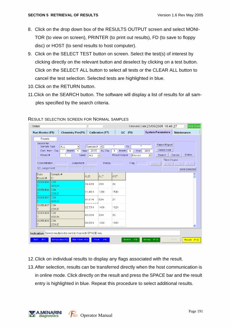
SECTION 5 RETRIEVAL OF RESULTS Version 1.6 Rev May 2005
8. Click on the drop down box of the RESULTS OUTPUT screen and select MONI-
TOR (to view on screen), PRINTER (to print out results), FD (to save to floppy
disc) or HOST (to send results to host computer).
9. Click on the SELECT TEST button on screen. Select the test(s) of interest by
clicking directly on the relevant button and deselect by clicking on a test button.
Click on the SELECT ALL button to select all tests or the CLEAR ALL button to
cancel the test selection. Selected tests are highlighted in blue.
10.Click on the RETURN button.
11.Click on the SEARCH button. The software will display a list of results for all sam-
ples specified by the search criteria.
RESULT SELECTION SCREEN FOR NORMAL SAMPLES
12.Click on individual results to display any flags associated with the result.
13.After selection, results can be transferred directly when the host communication is
in online mode. Click directly on the result and press the SPACE bar and the result
entry is highlighted in blue. Repeat this procedure to select additional results.
Page 191Operator Manual
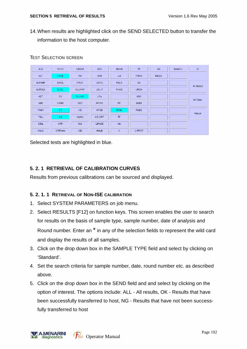
SECTION 5 RETRIEVAL OF RESULTS Version 1.6 Rev May 2005
14.When results are highlighted click on the SEND SELECTED button to transfer the
information to the host computer.
TEST SELECTION SCREEN
Selected tests are highlighted in blue.
5. 2. 1 RETRIEVAL OF CALIBRATION CURVES
Results from previous calibrations can be sourced and displayed.
5. 2. 1. 1 RETRIEVAL OF NON-ISE CALIBRATION
1. Select SYSTEM PARAMETERS on job menu.
2. Select RESULTS [F12] on function keys. This screen enables the user to search
for results on the basis of sample type, sample number, date of analysis and
Round number. Enter an * in any of the selection fields to represent the wild card
and display the results of all samples.
3. Click on the drop down box in the SAMPLE TYPE field and select by clicking on
‘Standard’.
4. Set the search criteria for sample number, date, round number etc. as described
above.
5. Click on the drop down box in the SEND field and and select by clicking on the
option of interest. The options include: ALL - All results, OK - Results that have
been successfully transferred to host, NG - Results that have not been success-
fully transferred to host
Page 192Operator Manual
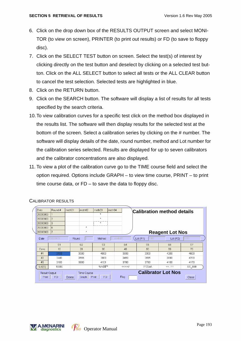
SECTION 5 RETRIEVAL OF RESULTS Version 1.6 Rev May 2005
6. Click on the drop down box of the RESULTS OUTPUT screen and select MONI-
TOR (to view on screen), PRINTER (to print out results) or FD (to save to floppy
disc).
7. Click on the SELECT TEST button on screen. Select the test(s) of interest by
clicking directly on the test button and deselect by clicking on a selected test but-
ton. Click on the ALL SELECT button to select all tests or the ALL CLEAR button
to cancel the test selection. Selected tests are highlighted in blue.
8. Click on the RETURN button.
9. Click on the SEARCH button. The software will display a list of results for all tests
specified by the search criteria.
10.To view calibration curves for a specific test click on the method box displayed in
the results list. The software will then display results for the selected test at the
bottom of the screen. Select a calibration series by clicking on the # number. The
software will display details of the date, round number, method and Lot number for
the calibration series selected. Results are displayed for up to seven calibrators
and the calibrator concentrations are also displayed.
11. To view a plot of the calibration curve go to the TIME course field and select the
option required. Options include GRAPH – to view time course, PRINT – to print
time course data, or FD – to save the data to floppy disc.
CALIBRATOR RESULTS
Calibrator Lot Nos
Reagent Lot Nos
Calibration method details
Page 193Operator Manual
SECTION 5 RETRIEVAL OF RESULTS Version 1.6 Rev May 2005
5. 2. 1. 2 RETRIEVAL OF ISE CALIBRATIONS
1. Select SYSTEM PARAMETERS on job menu.
2. Select RESULTS [F12] on function keys. This screen enables the user to search
for results on the basis of sample type, sample number, date of analysis and
Round number. Enter an * in any of the selection fields to represent the wild card
and display the results of all samples.
3. Click on the drop down box in the SAMPLE TYPE field and select by clicking on
‘ISE Standard’.
4. Set the search criteria for sample number, date, round number etc, as described
above.
5. Click on the drop down box in the SEND field and and select by clicking on the
option of interest. The options include: ALL - All results, OK - Results that have
been successfully transferred to host, NG - Results that have not been success-
fully transferred to host
6. Click on the drop down box of the RESULTS OUTPUT screen and select MONI-
TOR (to view on screen), PRINTER (to print out results), FD (to save to floppy
disc) or HOST (to send results to host computer).
7. Click on the SELECT TEST button on screen. Select the ISE test option by click-
ing directly on the button. Selected tests are highlighted in blue.
8. Click on the RETURN button.
9. Click on the SEARCH button. The software will display a list of results for all ISE
tests specified by the search criteria.
Page 194Operator Manual
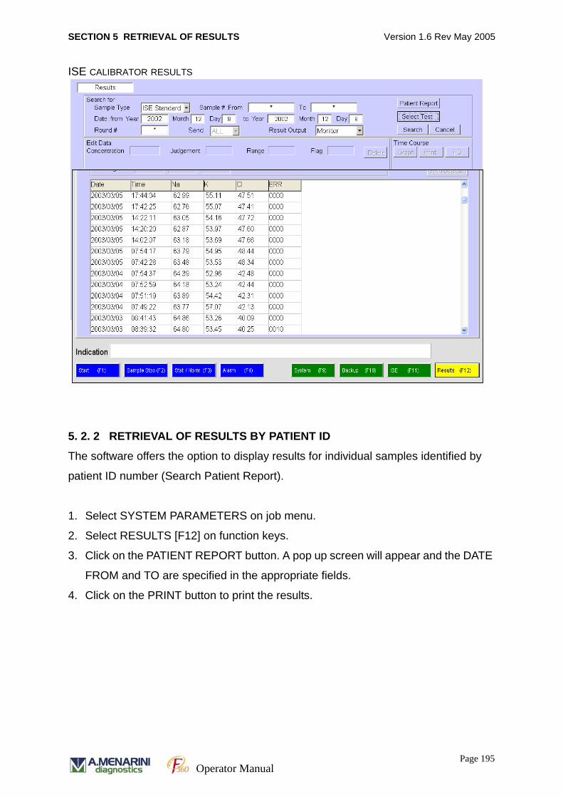
SECTION 5 RETRIEVAL OF RESULTS Version 1.6 Rev May 2005
ISE CALIBRATOR RESULTS
5. 2. 2 RETRIEVAL OF RESULTS BY PATIENT ID
The software offers the option to display results for individual samples identified by
patient ID number (Search Patient Report).
1. Select SYSTEM PARAMETERS on job menu.
2. Select RESULTS [F12] on function keys.
3. Click on the PATIENT REPORT button. A pop up screen will appear and the DATE
FROM and TO are specified in the appropriate fields.
4. Click on the PRINT button to print the results.
Page 195Operator Manual
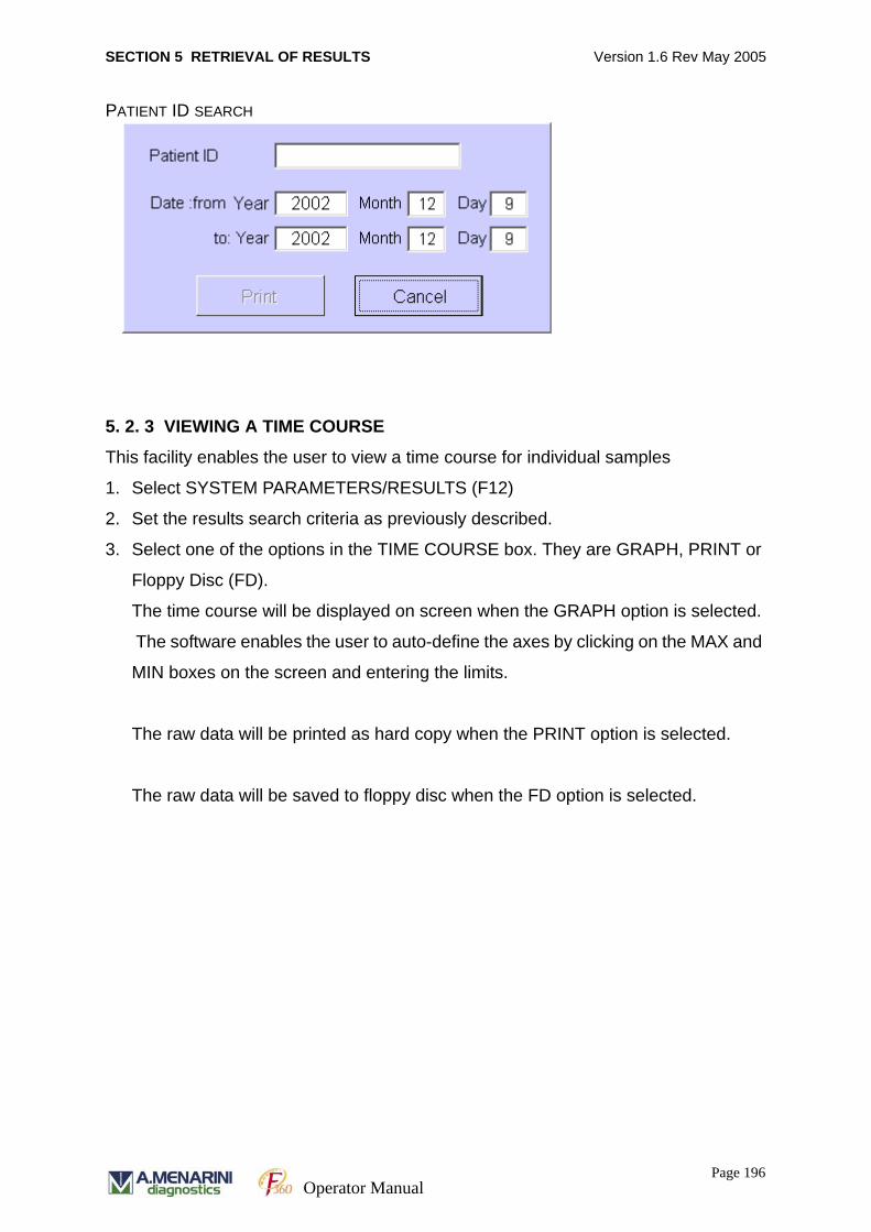
SECTION 5 RETRIEVAL OF RESULTS Version 1.6 Rev May 2005
PATIENT ID SEARCH
5. 2. 3 VIEWING A TIME COURSE
This facility enables the user to view a time course for individual samples
1. Select SYSTEM PARAMETERS/RESULTS (F12)
2. Set the results search criteria as previously described.
3. Select one of the options in the TIME COURSE box. They are GRAPH, PRINT or
Floppy Disc (FD).
The time course will be displayed on screen when the GRAPH option is selected.
The software enables the user to auto-define the axes by clicking on the MAX and
MIN boxes on the screen and entering the limits.
The raw data will be printed as hard copy when the PRINT option is selected.
The raw data will be saved to floppy disc when the FD option is selected.
Page 196Operator Manual
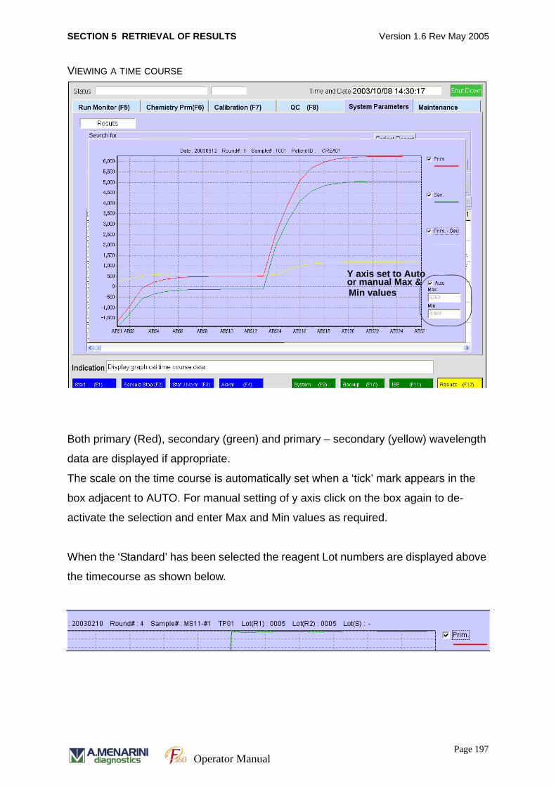
SECTION 5 RETRIEVAL OF RESULTS Version 1.6 Rev May 2005
VIEWING A TIME COURSE
Both primary (Red), secondary (green) and primary – secondary (yellow) wavelength
data are displayed if appropriate.
The scale on the time course is automatically set when a ‘tick’ mark appears in the
box adjacent to AUTO. For manual setting of y axis click on the box again to de-
activate the selection and enter Max and Min values as required.
When the ‘Standard’ has been selected the reagent Lot numbers are displayed above
the timecourse as shown below.
Y axis set to Autoor manual Max & Min values
Page 197Operator Manual
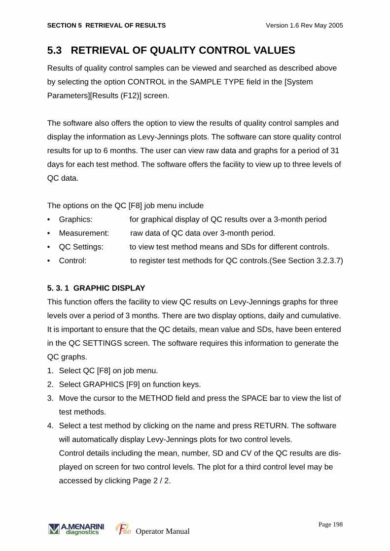
SECTION 5 RETRIEVAL OF RESULTS Version 1.6 Rev May 2005
5.3 RETRIEVAL OF QUALITY CONTROL VALUESResults of quality control samples can be viewed and searched as described above
by selecting the option CONTROL in the SAMPLE TYPE field in the [System
Parameters][Results (F12)] screen.
The software also offers the option to view the results of quality control samples and
display the information as Levy-Jennings plots. The software can store quality control
results for up to 6 months. The user can view raw data and graphs for a period of 31
days for each test method. The software offers the facility to view up to three levels of
QC data.
The options on the QC [F8] job menu include
• Graphics: for graphical display of QC results over a 3-month period
• Measurement: raw data of QC data over 3-month period.
• QC Settings: to view test method means and SDs for different controls.
• Control: to register test methods for QC controls.(See Section 3.2.3.7)
5. 3. 1 GRAPHIC DISPLAY
This function offers the facility to view QC results on Levy-Jennings graphs for three
levels over a period of 3 months. There are two display options, daily and cumulative.
It is important to ensure that the QC details, mean value and SDs, have been entered
in the QC SETTINGS screen. The software requires this information to generate the
QC graphs.
1. Select QC [F8] on job menu.
2. Select GRAPHICS [F9] on function keys.
3. Move the cursor to the METHOD field and press the SPACE bar to view the list of
test methods.
4. Select a test method by clicking on the name and press RETURN. The software
will automatically display Levy-Jennings plots for two control levels.
Control details including the mean, number, SD and CV of the QC results are dis-
played on screen for two control levels. The plot for a third control level may be
accessed by clicking Page 2 / 2.
Page 198Operator Manual

SECTION 5 RETRIEVAL OF RESULTS Version 1.6 Rev May 2005
5. In the DISPLAY TYPE field select the DAILY button to display QC results for each
day and CUMULATIVE to display cumulative values.
Results are plotted in black for normal values. If Westgard rules are applied,
results are plotted in YELLOW if they violate a WARNING rule and RED if they
violate an ERROR rule. Results indicated as an ERROR will not be included in the
overall mean, CV and SD values presented on screen.
QC RESULTS DISPLAY SCREEN.
Daily display: Individual QC sample results are displayed for each day.
Cumulative results QC sample results are plotted cumulatively for each day.
All the results in one day are plotted on the one vertical axis.
for both levelsResults summary
Click page no.to view Level 3 control
Page 199Operator Manual
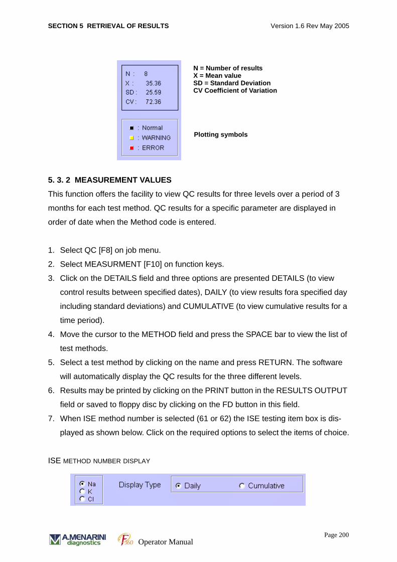
SECTION 5 RETRIEVAL OF RESULTS Version 1.6 Rev May 2005
5. 3. 2 MEASUREMENT VALUES
This function offers the facility to view QC results for three levels over a period of 3
months for each test method. QC results for a specific parameter are displayed in
order of date when the Method code is entered.
1. Select QC [F8] on job menu.
2. Select MEASURMENT [F10] on function keys.
3. Click on the DETAILS field and three options are presented DETAILS (to view
control results between specified dates), DAILY (to view results fora specified day
including standard deviations) and CUMULATIVE (to view cumulative results for a
time period).
4. Move the cursor to the METHOD field and press the SPACE bar to view the list of
test methods.
5. Select a test method by clicking on the name and press RETURN. The software
will automatically display the QC results for the three different levels.
6. Results may be printed by clicking on the PRINT button in the RESULTS OUTPUT
field or saved to floppy disc by clicking on the FD button in this field.
7. When ISE method number is selected (61 or 62) the ISE testing item box is dis-
played as shown below. Click on the required options to select the items of choice.
ISE METHOD NUMBER DISPLAY
Plotting symbols
N = Number of resultsX = Mean valueSD = Standard DeviationCV Coefficient of Variation
Page 200Operator Manual
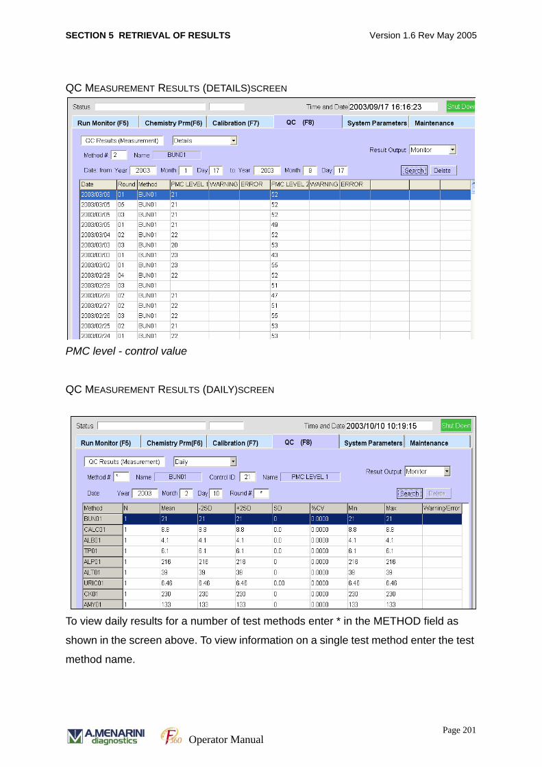
SECTION 5 RETRIEVAL OF RESULTS Version 1.6 Rev May 2005
QC MEASUREMENT RESULTS (DETAILS)SCREEN
PMC level - control value
QC MEASUREMENT RESULTS (DAILY)SCREEN
To view daily results for a number of test methods enter * in the METHOD field as
shown in the screen above. To view information on a single test method enter the test
method name.
Page 201Operator Manual
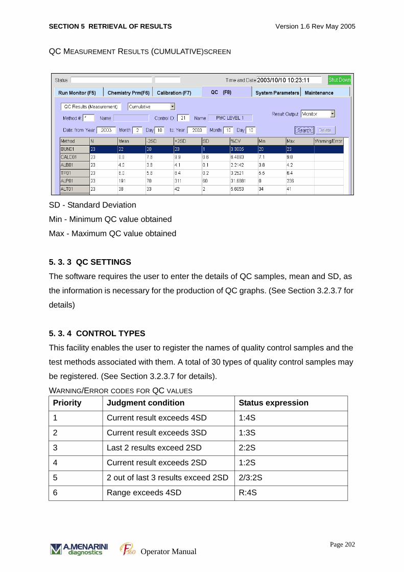
SECTION 5 RETRIEVAL OF RESULTS Version 1.6 Rev May 2005
QC MEASUREMENT RESULTS (CUMULATIVE)SCREEN
SD - Standard Deviation
Min - Minimum QC value obtained
Max - Maximum QC value obtained
5. 3. 3 QC SETTINGS
The software requires the user to enter the details of QC samples, mean and SD, as
the information is necessary for the production of QC graphs. (See Section 3.2.3.7 for
details)
5. 3. 4 CONTROL TYPES
This facility enables the user to register the names of quality control samples and the
test methods associated with them. A total of 30 types of quality control samples may
be registered. (See Section 3.2.3.7 for details).
WARNING/ERROR CODES FOR QC VALUES
Priority Judgment condition Status expression
1 Current result exceeds 4SD 1:4S
2 Current result exceeds 3SD 1:3S
3 Last 2 results exceed 2SD 2:2S
4 Current result exceeds 2SD 1:2S
5 2 out of last 3 results exceed 2SD 2/3:2S
6 Range exceeds 4SD R:4S
Page 202Operator Manual
SECTION 5 RETRIEVAL OF RESULTS Version 1.6 Rev May 2005
7 7 continue points trend 7:T[+] Increasing
7:T[-] Decreasing
8 Any 4 results exceed 1SD 4:1S
9 Any 3 results exceed 1SD 3:1S
10 10 results same side of mean 10:T[+] Greater than mean
10:T[-] Less than mean
10:X(-)F Reject when 10
consecutive control
measurements fall on one
side of the mean.
Page 203Operator Manual
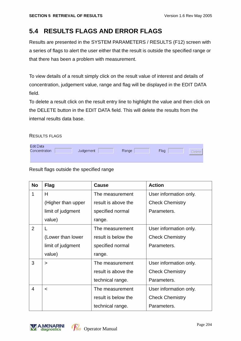
SECTION 5 RETRIEVAL OF RESULTS Version 1.6 Rev May 2005
5.4 RESULTS FLAGS AND ERROR FLAGSResults are presented in the SYSTEM PARAMETERS / RESULTS (F12) screen with
a series of flags to alert the user either that the result is outside the specified range or
that there has been a problem with measurement.
To view details of a result simply click on the result value of interest and details of
concentration, judgement value, range and flag will be displayed in the EDIT DATA
field.
To delete a result click on the result entry line to highlight the value and then click on
the DELETE button in the EDIT DATA field. This will delete the results from the
internal results data base.
RESULTS FLAGS
Result flags outside the specified range
No Flag Cause Action
1 H
(Higher than upper
limit of judgment
value)
The measurement
result is above the
specified normal
range.
User information only.
Check Chemistry
Parameters.
2 L
(Lower than lower
limit of judgment
value)
The measurement
result is below the
specified normal
range.
User information only.
Check Chemistry
Parameters.
3 > The measurement
result is above the
technical range.
User information only.
Check Chemistry
Parameters.
4 < The measurement
result is below the
technical range.
User information only.
Check Chemistry
Parameters.
Page 204Operator Manual

SECTION 5 RETRIEVAL OF RESULTS Version 1.6 Rev May 2005
Error flags on Routine measurement screen and Results printout
Flag Brief explanation Description
SS Sample short Insufficient sample in primary tube or sample cup.
SI1 No reagent in
cuvette
Reagent not detected in cuvette on sample
dispense.
SI2 No diluent in cuvette Diluent not detected in cuvette on sample dispense.
R1S Insufficient Reagent
1
Insufficient reagent in bottle or reagent volume is
zero on inventory.
R2S Insufficient Reagent
2
Insufficient reagent in bottle or reagent volume is
zero on inventory.
DS Insufficient Diluent Insufficient diluent in bottle or diluent volume is zero
on inventory.
WS Insufficient Wash
Solution
Insufficient wash solution in bottle or volume is zero
on inventory.
TE1 IRU temperature low IRU temperature is lower than 36.5ºC.
TE2 IRU temperature
high
IRU temperature is higher than 37.5ºC.
TE3 RCU temperature
high
RCU temperature is higher than 15 ºC.
R1B No Reagent 1 bottle Reagent 1 bottle is not registered.
R2B No Reagent 2 bottle Reagent 2 bottle is not registered.
DB No diluent bottle Diluent bottle is not registered.
WB No wash solution
bottle
Wash solution bottle is not registered.
IE1 No response from
ISE
ISE module is not responding to sample start
command sent from analyser.
IE2 No result from ISE ISE module is not sending result data to analyser.
EST Error during run Sampling has been terminated with an error.
LOT Erroneous lot number details input
R1W RPT wash failed Reagent 1 probe wash between defined methods
failed.
.
Page 205Operator Manual
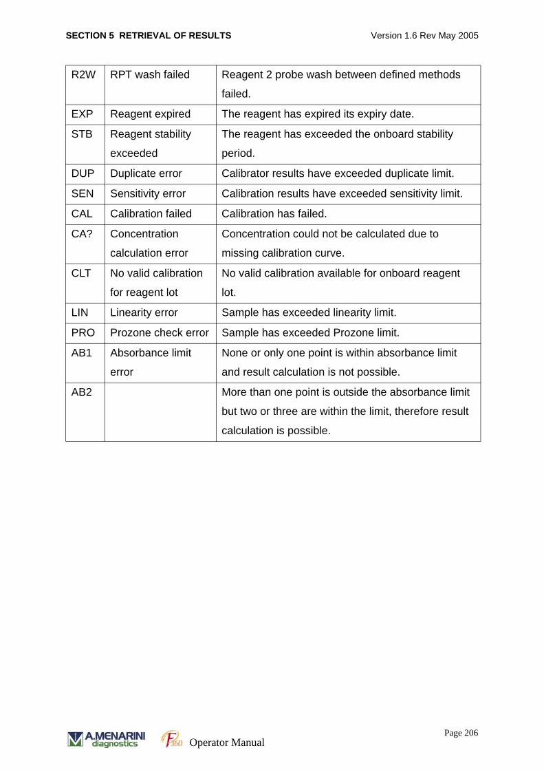
SECTION 5 RETRIEVAL OF RESULTS Version 1.6 Rev May 2005
R2W RPT wash failed Reagent 2 probe wash between defined methods
failed.
EXP Reagent expired The reagent has expired its expiry date.
STB Reagent stability
exceeded
The reagent has exceeded the onboard stability
period.
DUP Duplicate error Calibrator results have exceeded duplicate limit.
SEN Sensitivity error Calibration results have exceeded sensitivity limit.
CAL Calibration failed Calibration has failed.
CA? Concentration
calculation error
Concentration could not be calculated due to
missing calibration curve.
CLT No valid calibration
for reagent lot
No valid calibration available for onboard reagent
lot.
LIN Linearity error Sample has exceeded linearity limit.
PRO Prozone check error Sample has exceeded Prozone limit.
AB1 Absorbance limit
error
None or only one point is within absorbance limit
and result calculation is not possible.
AB2 More than one point is outside the absorbance limit
but two or three are within the limit, therefore result
calculation is possible.
Page 206Operator Manual
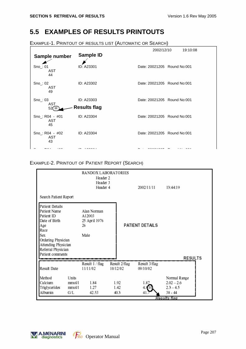
SECTION 5 RETRIEVAL OF RESULTS Version 1.6 Rev May 2005
5.5 EXAMPLES OF RESULTS PRINTOUTSEXAMPLE-1. PRINTOUT OF RESULTS LIST (AUTOMATIC OR SEARCH)
EXAMPLE-2. PRINTOUT OF PATIENT REPORT (SEARCH)
2002/12/10 19:10:08 Sno_: 01 ID: A23301 Date: 20021205 Round No:001 AST 44 Sno_: 02 ID: A23302 Date: 20021205 Round No:001 AST 49 Sno_: 03 ID: A23303 Date: 20021205 Round No:001 AST 52 H Sno_: R04 - #01 ID: A23304 Date: 20021205 Round No:001 AST 45 Sno_: R04 - #02 ID: A23304 Date: 20021205 Round No:001 AST 43 S R04 #03 ID A23304 D t 20021205 R d N 001
Sample number Sample ID
Results flag
Page 207Operator Manual
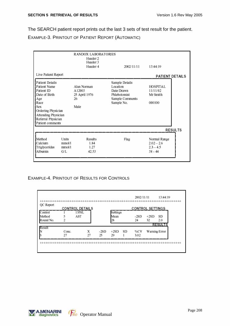
SECTION 5 RETRIEVAL OF RESULTS Version 1.6 Rev May 2005
The SEARCH patient report prints out the last 3 sets of test result for the patient.
EXAMPLE-3. PRINTOUT OF PATIENT REPORT (AUTOMATIC)
EXAMPLE-4. PRINTOUT OF RESULTS FOR CONTROLS
Page 208Operator Manual
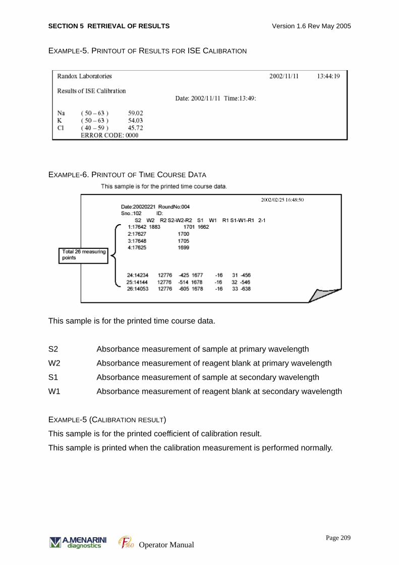
SECTION 5 RETRIEVAL OF RESULTS Version 1.6 Rev May 2005
EXAMPLE-5. PRINTOUT OF RESULTS FOR ISE CALIBRATION
EXAMPLE-6. PRINTOUT OF TIME COURSE DATA
This sample is for the printed time course data.
S2 Absorbance measurement of sample at primary wavelength
W2 Absorbance measurement of reagent blank at primary wavelength
S1 Absorbance measurement of sample at secondary wavelength
W1 Absorbance measurement of reagent blank at secondary wavelength
EXAMPLE-5 (CALIBRATION RESULT)
This sample is for the printed coefficient of calibration result.
This sample is printed when the calibration measurement is performed normally.
Page 209Operator Manual

SECTION 5 RETRIEVAL OF RESULTS Version 1.6 Rev May 2005
1. Linear
2. Point to point
3 Log-Logit
Page 210Operator Manual

SECTION 5 RETRIEVAL OF RESULTS Version 1.6 Rev May 2005
4. Spline
5. Exponential
Page 211Operator Manual
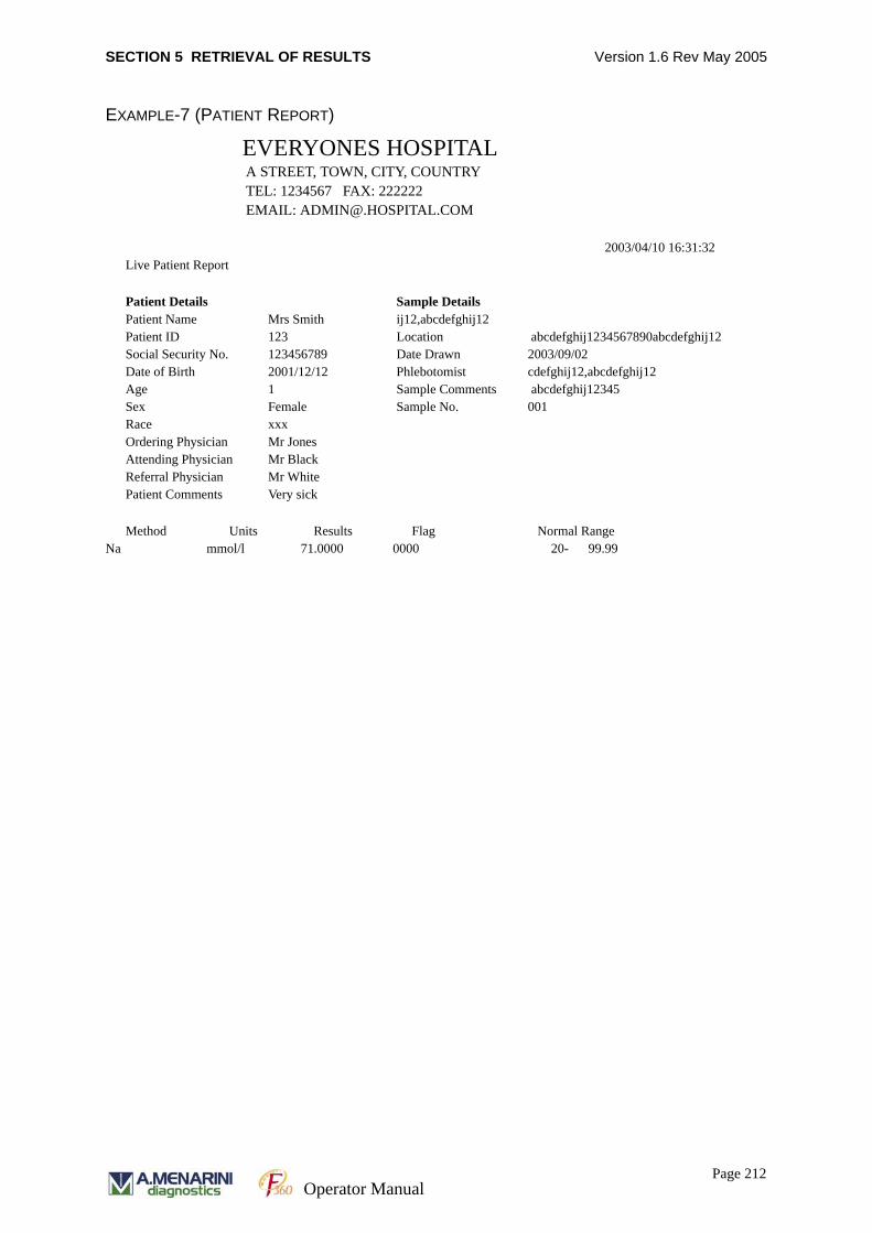
SECTION 5 RETRIEVAL OF RESULTS Version 1.6 Rev May 2005
EXAMPLE-7 (PATIENT REPORT)
EVERYONES HOSPITALA STREET, TOWN, CITY, COUNTRYTEL: 1234567 FAX: 222222EMAIL: [email protected]
2003/04/10 16:31:32Live Patient Report
Patient Details Sample DetailsPatient Name Mrs Smith ij12,abcdefghij12Patient ID 123 Location abcdefghij1234567890abcdefghij12Social Security No. 123456789 Date Drawn 2003/09/02Date of Birth 2001/12/12 Phlebotomist cdefghij12,abcdefghij12Age 1 Sample Comments abcdefghij12345Sex Female Sample No. 001Race xxxOrdering Physician Mr JonesAttending Physician Mr BlackReferral Physician Mr WhitePatient Comments Very sick
Method Units Results Flag Normal RangeNa mmol/l 71.0000 0000 20- 99.99
Page 212Operator Manual

SECTION 6 MAINTENANCE Version 1.6 Rev May 2005
SECTION 6
MAINTENANCE
Page 213
Operator Manual
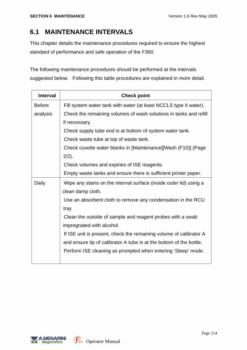
SECTION 6 MAINTENANCE Version 1.6 Rev May 2005
6.1 MAINTENANCE INTERVALS This chapter details the maintenance procedures required to ensure the highest
standard of performance and safe operation of the F360.
The following maintenance procedures should be performed at the intervals
suggested below. Following this table procedures are explained in more detail.
Interval Check point
Before
analysis
Fill system water tank with water (at least NCCLS type II water).
Check the remaining volumes of wash solutions in tanks and refill
if necessary.
Check supply tube end is at bottom of system water tank.
Check waste tube at top of waste tank.
Check cuvette water blanks in [Maintenance][Wash (F10)] (Page
2/2).
Check volumes and expiries of ISE reagents.
Empty waste tanks and ensure there is sufficient printer paper.
Daily Wipe any stains on the internal surface (inside outer lid) using a
clean damp cloth.
Use an absorbent cloth to remove any condensation in the RCU
tray
Clean the outside of sample and reagent probes with a swab
impregnated with alcohol.
If ISE unit is present, check the remaining volume of calibrator A
and ensure tip of calibrator A tube is at the bottom of the bottle.
Perform ISE cleaning as prompted when entering ‘Sleep’ mode.
Page 214
Operator Manual
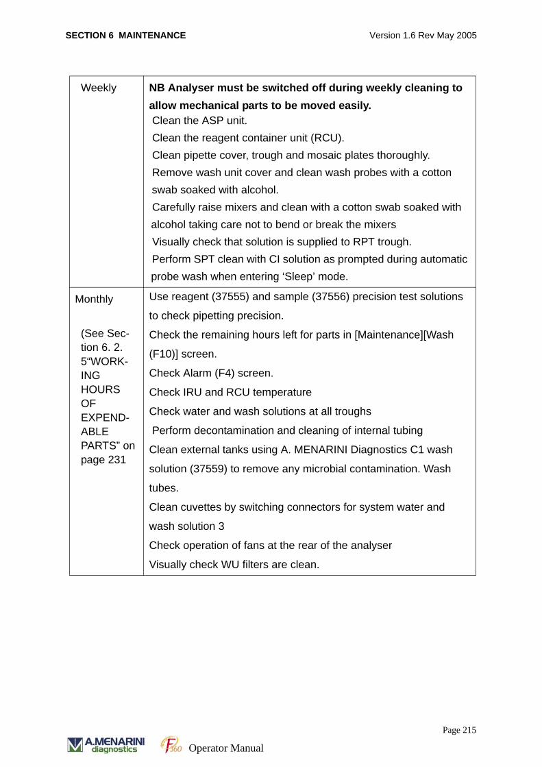
SECTION 6 MAINTENANCE Version 1.6 Rev May 2005
Weekly NB Analyser must be switched off during weekly cleaning to allow mechanical parts to be moved easily. Clean the ASP unit. Clean the reagent container unit (RCU). Clean pipette cover, trough and mosaic plates thoroughly. Remove wash unit cover and clean wash probes with a cotton swab soaked with alcohol. Carefully raise mixers and clean with a cotton swab soaked with alcohol taking care not to bend or break the mixers Visually check that solution is supplied to RPT trough. Perform SPT clean with CI solution as prompted during automatic probe wash when entering ‘Sleep’ mode.
Monthly
(See Sec-tion 6. 2. 5“WORK-ING HOURS OF EXPEND-ABLE PARTS” on page 231
Use reagent (37555) and sample (37556) precision test solutions
to check pipetting precision.
Check the remaining hours left for parts in [Maintenance][Wash
(F10)] screen.
Check Alarm (F4) screen.
Check IRU and RCU temperature
Check water and wash solutions at all troughs
Perform decontamination and cleaning of internal tubing
Clean external tanks using A. MENARINI Diagnostics C1 wash
solution (37559) to remove any microbial contamination. Wash
tubes.
Clean cuvettes by switching connectors for system water and
wash solution 3
Check operation of fans at the rear of the analyser
Visually check WU filters are clean.
Page 215
Operator Manual
SECTION 6 MAINTENANCE Version 1.6 Rev May 2005
6. 1. 1 DAILY MAINTENANCE
1. Pure Water and Effluent Tanks
Checks: pure water tank is full (fill as necessary)
effluent tanks are empty (empty as necessary)
tube tip of water tank is in contact with bottom of tank
tube tip of effluent tank is well above effluent level to avoid
back flow.
2. Detergent Tank
Checks: wash solution tanks are full (fill as necessary)
tube tip of detergent tank is in contact with bottom of tank
3. Click on [Maintenance] [Sequence (F9)] to perform a cuvette check. To view the
cuvette water blanks go to [Maintenance] [Wash (F10)] screen. If any cuvettes are
flagged as being over the judgement value perform a cuvette wash and recheck
screen. If still above judgement value, remove affected cuvette from IRU and
wash manually in 0.1 M HCl. Replace cuvette and perform cuvette check - contact
Service company if this does not resolve the problem.
4. Clean the inside of the sample and reagent probes with the probe cleaning tool.
Clean the outside of the probes with a piece of gauze soaked in methanol. Always
wipe downwards from nozzle body to tip.
As required Exchange of halogen lamp (every 1000 hours).
Exchange of syringe plunger tip (every approx. 600 hours).
Exchange of diaphragm pump (every 2000 hours).
Exchange of cuvette (based on the measurement of water blank).
Exchange of stirrer
Exchange of pipette nozzle
Replace ISE electrodes
Use probe cleaning tool to clean inside of the sample probe and
reagent probe.
Page 216
Operator Manual
SECTION 6 MAINTENANCE Version 1.6 Rev May 2005
5. Wipe all surfaces with a clean damp cloth.
6. Use an absorbent cloth to remove any condensation in the RCU tray.
7. Check printing paper and replace as necessary.
8. If ISE unit (optional) is present carry out additional checks below.
Ensure sufficient volume of Calibrator A – gently agitate Calibrator A bottle.
Ensure tip of the Calibrator A tube is in contact with the bottom of the bottle
In the event that the tube comes out of the calibrator A bottle perform ISE prime
10 times.
Remove ISE cover and swing out ISE module, checking for any spillage around
the sampling port. Clean with a swab impregnated with alcohol if requiredto
remove any crystalline deposits, taking care not to contaminate the sampling port.
Swing ISE module back into unit and replace ISE cover.
Daily cleaning procedure should take less than 5 minutes.
9. Perform ISE cleaning procedure at end of daily analysis by placing 500μl of ISE
cleaning solution in a sample cup at position 18 in the ASP tray and use the ‘ISE
Clean’ function in the [Maintenance] [Sequence (F9)] screen.
6. 1. 2 WEEKLY MAINTENANCE
Please note that to carry out these procedures effectively the analyser must be
completely powered off so that mechanical parts can be moved easily. It is suggested
that the RCU tray be removed and placed in a refrigerator while the cleaning is being
carried out.
1. Clean Automatic Sampling Unit (ASP) with a clean damp cloth.
2. Clean Reagent Container Unit (RCU) with a clean damp cloth.
Page 217
Operator Manual
SECTION 6 MAINTENANCE Version 1.6 Rev May 2005
3. Clean pipette cover, trough and mosaic plates thoroughly with a clean damp cloth
removing relevant sections if necessary.
4. Remove wash unit cover, carefully lift wash unit up to allow better access and
clean wash unit probes with a swab impregnated with alcohol.
5. Carefully raise mixers and clean with a swab impregnated with alcohol taking care
not to bend or break the mixers.
6. At the end of each day prior to putting the system into sleep mode, place a cup of
wash solution C1 in sample position 18 for the automatic probe wash.
Once cleaning procedure has been finished replace RCU tray and power on the
analyser and PC. Weekly cleaning procedure should take approximately 5 – 10
minutes. Please see Section 6.2.8 for details of cleaning procedures.
6. 1. 3 MONTHLY MAINTENANCE
1. Carry out a sample and reagent precision check using Reagent Precision Test
solution (Cat. No. 37555), Sample Precision Test solution (Cat. No. 37556) and
Acid Wash Solution (37557). See kit inserts for procedures. If the results of these
checks are outside defined acceptable limits please contact A. MENARINI Diag-
nostics Technical Support.
2. Check the remaining hours of parts on the maintenance wash screen.
3. Check Alarm Log and refer to error code section of this manual for any unex-
plained error codes.
4. Check IRU and RCU temperature.
5. Perform SPT/RPT (W) and SPT/RPT (C) washes from the [Maintenance] [Wash
(F10)] screen.
Page 218
Operator Manual
SECTION 6 MAINTENANCE Version 1.6 Rev May 2005
6. Visually check water and wash solutions at all troughs.
7. Perform decontamination and cleaning of internal tubing using the Tubing Wash
instructions . See section 6. 2. 3“TUBING WASH” on page 228.
8. Clean waste tanks using dilute hypochlorite solution to remove any microbial con-
tamination.
9. Check the condition of the three fans located at the rear of the chassis to ensure
that they are operating normally.
6. 1. 4 PERIODIC MAINTENANCE
Periodic checks should be carried out at regular intervals based on the use and
throughput of the analyser. To determine hours of use for various parts go to
[Maintenance][Wash (F10)] screen and perform the following if countdown timer has
reached zero hours.
• Exchange the halogen lamp
• Replace syringe tips
• Replace diaphragm pumps
• Replace pipette nozzles
• Replace cuvettes.
• Use probe cleaning jig to remove blockages if they occur.
During analysis, periodically check the levels and tube positions in the purified water
and waste tanks.
Page 219
Operator Manual

SECTION 6 MAINTENANCE Version 1.6 Rev May 2005
6.2 MAINTENANCE SCREEN The maintenance screen provides test function operations performed by each unit
and displays the status of various sensors.
6. 2. 1 SYSTEM CHECKS
The MECHANICAL MAINTENANCE screen enables the user to check various
operating functions and sensors in F360 analyser.
1. Select MAINTENANCE on the job menu.
2. Select SEQUENCE [F9] on the function keys.
3. Select each check by clicking on the START button as required. The instrument
will automatically commence the system check.
MAINTENANCE SCREEN
System Checks Sensor checks
Page 220
Operator Manual
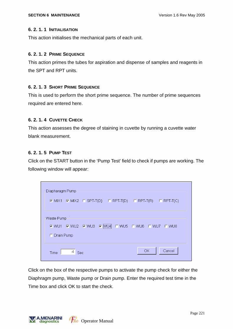
SECTION 6 MAINTENANCE Version 1.6 Rev May 2005
6. 2. 1. 1 INITIALISATION
This action initialises the mechanical parts of each unit.
6. 2. 1. 2 PRIME SEQUENCE
This action primes the tubes for aspiration and dispense of samples and reagents in
the SPT and RPT units.
6. 2. 1. 3 SHORT PRIME SEQUENCE
This is used to perform the short prime sequence. The number of prime sequences
required are entered here.
6. 2. 1. 4 CUVETTE CHECK
This action assesses the degree of staining in cuvette by running a cuvette water
blank measurement.
6. 2. 1. 5 PUMP TEST
Click on the START button in the ‘Pump Test’ field to check if pumps are working. The
following window will appear:
Click on the box of the respective pumps to activate the pump check for either the
Diaphragm pump, Waste pump or Drain pump. Enter the required test time in the
Time box and click OK to start the check.
Page 221
Operator Manual
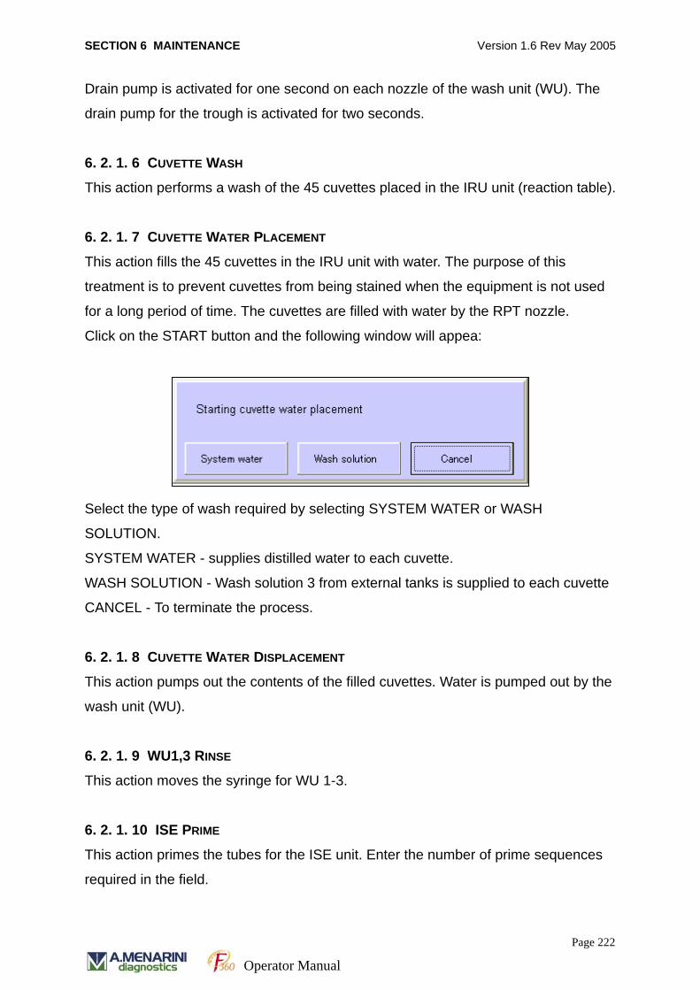
SECTION 6 MAINTENANCE Version 1.6 Rev May 2005
Drain pump is activated for one second on each nozzle of the wash unit (WU). The
drain pump for the trough is activated for two seconds.
6. 2. 1. 6 CUVETTE WASH
This action performs a wash of the 45 cuvettes placed in the IRU unit (reaction table).
6. 2. 1. 7 CUVETTE WATER PLACEMENT
This action fills the 45 cuvettes in the IRU unit with water. The purpose of this
treatment is to prevent cuvettes from being stained when the equipment is not used
for a long period of time. The cuvettes are filled with water by the RPT nozzle.
Click on the START button and the following window will appea:
Select the type of wash required by selecting SYSTEM WATER or WASH
SOLUTION.
SYSTEM WATER - supplies distilled water to each cuvette.
WASH SOLUTION - Wash solution 3 from external tanks is supplied to each cuvette
CANCEL - To terminate the process.
6. 2. 1. 8 CUVETTE WATER DISPLACEMENT
This action pumps out the contents of the filled cuvettes. Water is pumped out by the
wash unit (WU).
6. 2. 1. 9 WU1,3 RINSE
This action moves the syringe for WU 1-3.
6. 2. 1. 10 ISE PRIME
This action primes the tubes for the ISE unit. Enter the number of prime sequences
required in the field.
Page 222
Operator Manual
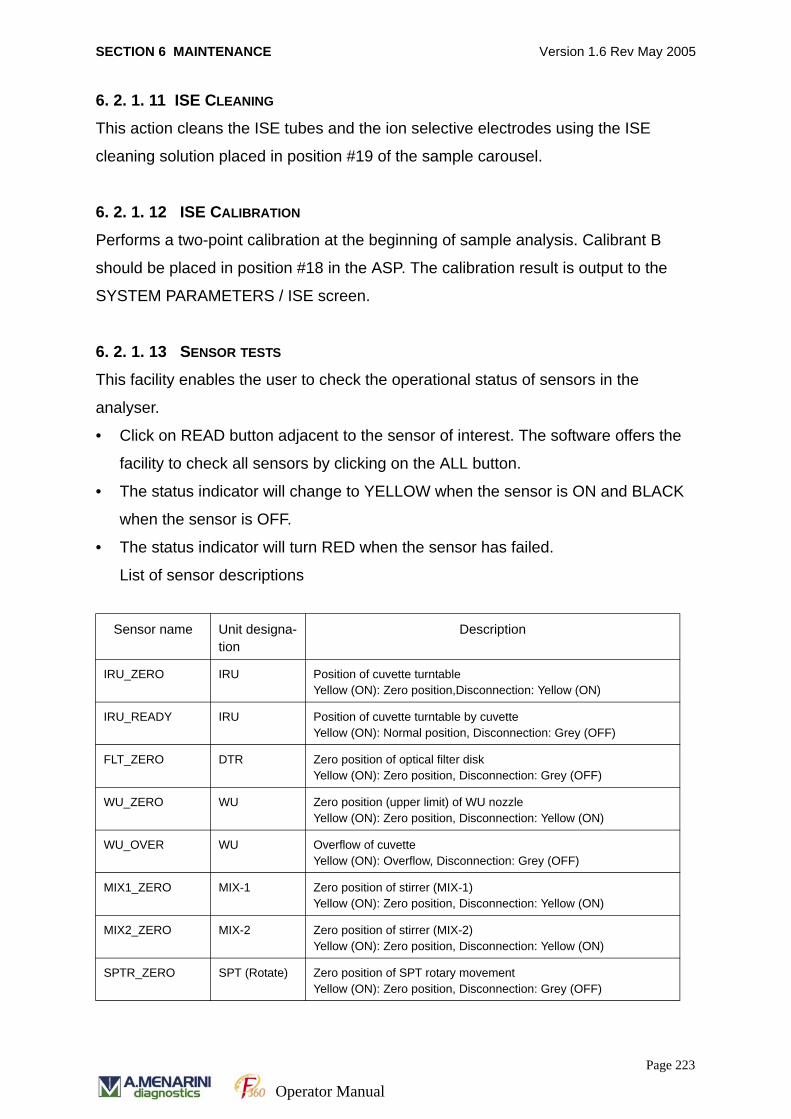
SECTION 6 MAINTENANCE Version 1.6 Rev May 2005
6. 2. 1. 11 ISE CLEANING
This action cleans the ISE tubes and the ion selective electrodes using the ISE
cleaning solution placed in position #19 of the sample carousel.
6. 2. 1. 12 ISE CALIBRATION
Performs a two-point calibration at the beginning of sample analysis. Calibrant B
should be placed in position #18 in the ASP. The calibration result is output to the
SYSTEM PARAMETERS / ISE screen.
6. 2. 1. 13 SENSOR TESTS
This facility enables the user to check the operational status of sensors in the
analyser.
• Click on READ button adjacent to the sensor of interest. The software offers the
facility to check all sensors by clicking on the ALL button.
• The status indicator will change to YELLOW when the sensor is ON and BLACK
when the sensor is OFF.
• The status indicator will turn RED when the sensor has failed.
List of sensor descriptions
Sensor name Unit designa-tion
Description
IRU_ZERO IRU Position of cuvette turntableYellow (ON): Zero position,Disconnection: Yellow (ON)
IRU_READY IRU Position of cuvette turntable by cuvetteYellow (ON): Normal position, Disconnection: Grey (OFF)
FLT_ZERO DTR Zero position of optical filter diskYellow (ON): Zero position, Disconnection: Grey (OFF)
WU_ZERO WU Zero position (upper limit) of WU nozzleYellow (ON): Zero position, Disconnection: Yellow (ON)
WU_OVER WU Overflow of cuvetteYellow (ON): Overflow, Disconnection: Grey (OFF)
MIX1_ZERO MIX-1 Zero position of stirrer (MIX-1)Yellow (ON): Zero position, Disconnection: Yellow (ON)
MIX2_ZERO MIX-2 Zero position of stirrer (MIX-2)Yellow (ON): Zero position, Disconnection: Yellow (ON)
SPTR_ZERO SPT (Rotate) Zero position of SPT rotary movementYellow (ON): Zero position, Disconnection: Grey (OFF)
Page 223
Operator Manual

SECTION 6 MAINTENANCE Version 1.6 Rev May 2005
SPTR_TS SPT (Rotate) Dispensation position of SPT rotary movement at troughYellow (ON): Dispensation position, Disconnection: Grey (OFF)
SPTU_ZERO SPT (Up &Down)
Zero position (upper limit) of SPT up-and-down movementYellow (ON): Zero position, Disconnection: Yellow (ON)
SPTU_DL SPT (Up &Down)
Zero position (lower limit) of SPT up-and-down movementYellow (ON): Lower limit, Disconnection: Yellow (ON)
SPTU_LL SPT (Up &Down)
Level detection of SPT up-and-down movementYellow (ON): Level, Disconnection: Grey (OFF)
SPTU_LOW SPT (Up &Down)
Not used
RPTR_ZERO RPT (Rotate) Zero position of RPT rotary movementYellow (ON): Zero position, Disconnection: Grey (OFF)
RPTR_TS RPT (Rotate) Dispensation position of RPT rotary movement at troughYellow (ON): Dispensation position, Disconnection: Grey (OFF)
RPTU_ZERO RPT (Up &Down)
Zero position (upper limit) of RPT up-and-down movementYellow (ON): Zero position, Disconnection: Yellow (ON)
RPTU_DL RPT (Up &Down)
Zero position (lower limit) of RPT up-and-down movementYellow (ON): Lower limit, Disconnection: Yellow (ON)
RPTU_LL RPT (Up &Down)
Level detection of RPT up-and-down movementYellow (ON): Level, Disconnection: Grey (OFF)
RPTU_LOW RPT (Up &Down)
Not used
TRF_OVER Trough Overflow at trough (SPT, RPT, MIX-1, MIX-2)Yellow (ON): Overflow, Disconnection: Grey (OFF)
IRU_24Vm IRU Monitor of 24 VDC (IRU motor)Yellow (ON): 24V
PP_24Vm PP Monitor of 24 VDC (SPP, RPP and WPP motors and solenoid valve)Yellow (ON): 24V
SWU_24Vm SWU Monitor of 24 VDC (SWU pump)Yellow (ON): 24V
BOT6_EMP External tank Spare
WPP_ZERO WPP Zero position (upper limit) of WPP syringeYellow (ON): Zero position, Disconnection: Yellow (ON)
SPP_ZERO SPP Zero position (upper limit) of SPP syringeYellow (ON): Zero position, Disconnection: Yellow (ON)
RPP_ZERO RPP Zero position (upper limit) of RPP syringeYellow (ON): Zero position, Disconnection: Yellow (ON)
BOT1_EMP External tank Empty detection of pure water tankYellow (ON): water exists (not empty)
Page 224
Operator Manual
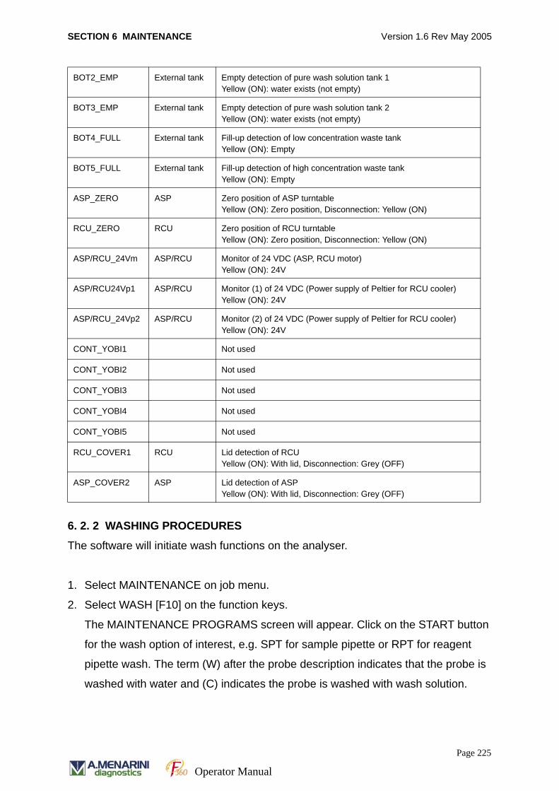
SECTION 6 MAINTENANCE Version 1.6 Rev May 2005
6. 2. 2 WASHING PROCEDURES
The software will initiate wash functions on the analyser.
1. Select MAINTENANCE on job menu.
2. Select WASH [F10] on the function keys.
The MAINTENANCE PROGRAMS screen will appear. Click on the START button
for the wash option of interest, e.g. SPT for sample pipette or RPT for reagent
pipette wash. The term (W) after the probe description indicates that the probe is
washed with water and (C) indicates the probe is washed with wash solution.
BOT2_EMP External tank Empty detection of pure wash solution tank 1Yellow (ON): water exists (not empty)
BOT3_EMP External tank Empty detection of pure wash solution tank 2Yellow (ON): water exists (not empty)
BOT4_FULL External tank Fill-up detection of low concentration waste tankYellow (ON): Empty
BOT5_FULL External tank Fill-up detection of high concentration waste tankYellow (ON): Empty
ASP_ZERO ASP Zero position of ASP turntableYellow (ON): Zero position, Disconnection: Yellow (ON)
RCU_ZERO RCU Zero position of RCU turntableYellow (ON): Zero position, Disconnection: Yellow (ON)
ASP/RCU_24Vm ASP/RCU Monitor of 24 VDC (ASP, RCU motor)Yellow (ON): 24V
ASP/RCU24Vp1 ASP/RCU Monitor (1) of 24 VDC (Power supply of Peltier for RCU cooler)Yellow (ON): 24V
ASP/RCU_24Vp2 ASP/RCU Monitor (2) of 24 VDC (Power supply of Peltier for RCU cooler)Yellow (ON): 24V
CONT_YOBI1 Not used
CONT_YOBI2 Not used
CONT_YOBI3 Not used
CONT_YOBI4 Not used
CONT_YOBI5 Not used
RCU_COVER1 RCU Lid detection of RCUYellow (ON): With lid, Disconnection: Grey (OFF)
ASP_COVER2 ASP Lid detection of ASPYellow (ON): With lid, Disconnection: Grey (OFF)
Page 225
Operator Manual
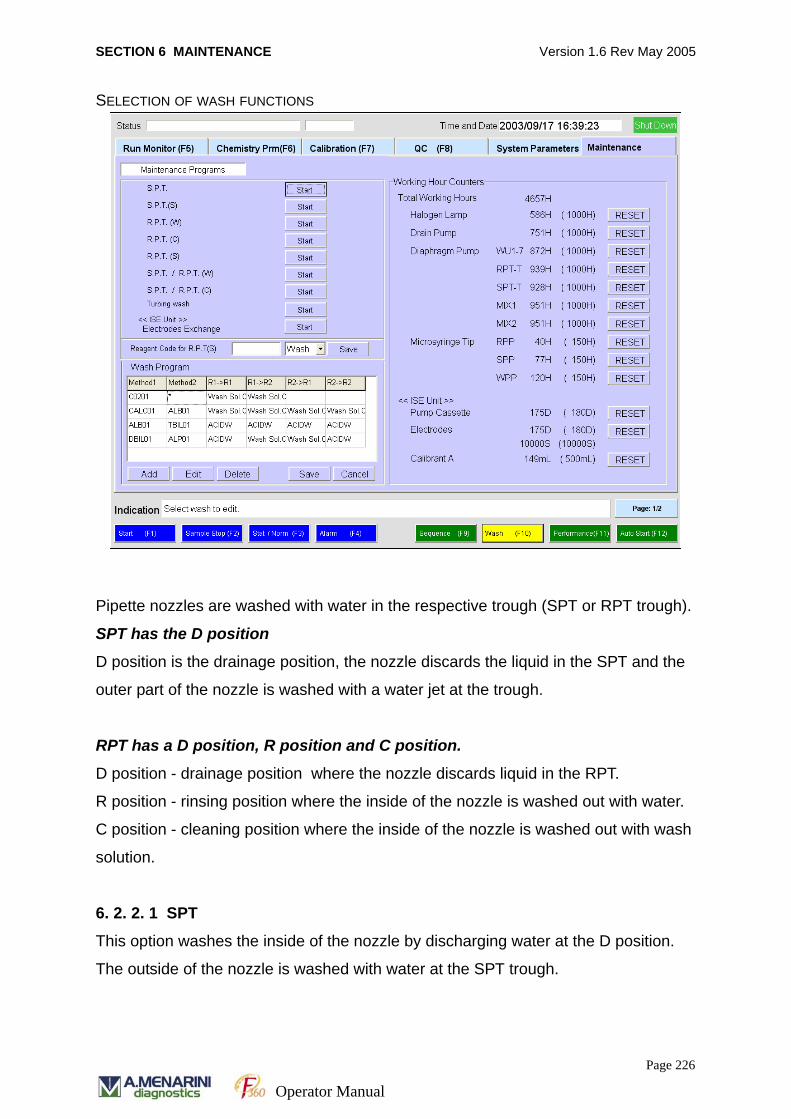
SECTION 6 MAINTENANCE Version 1.6 Rev May 2005
SELECTION OF WASH FUNCTIONS
Pipette nozzles are washed with water in the respective trough (SPT or RPT trough).
SPT has the D position
D position is the drainage position, the nozzle discards the liquid in the SPT and the
outer part of the nozzle is washed with a water jet at the trough.
RPT has a D position, R position and C position.
D position - drainage position where the nozzle discards liquid in the RPT.
R position - rinsing position where the inside of the nozzle is washed out with water.
C position - cleaning position where the inside of the nozzle is washed out with wash
solution.
6. 2. 2. 1 SPT
This option washes the inside of the nozzle by discharging water at the D position.
The outside of the nozzle is washed with water at the SPT trough.
Page 226
Operator Manual
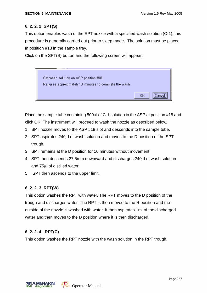
SECTION 6 MAINTENANCE Version 1.6 Rev May 2005
6. 2. 2. 2 SPT(S)
This option enables wash of the SPT nozzle with a specified wash solution (C-1), this
procedure is generally carried out prior to sleep mode. The solution must be placed
in position #18 in the sample tray.
Click on the SPT(S) button and the following screen will appear:
Place the sample tube containing 500μl of C-1 solution in the ASP at position #18 and
click OK. The instrument will proceed to wash the nozzle as described below.
1. SPT nozzle moves to the ASP #18 slot and descends into the sample tube.
2. SPT aspirates 240μl of wash solution and moves to the D position of the SPT
trough.
3. SPT remains at the D position for 10 minutes without movement.
4. SPT then descends 27.5mm downward and discharges 240μl of wash solution
and 75μl of distilled water.
5. SPT then ascends to the upper limit.
6. 2. 2. 3 RPT(W)
This option washes the RPT with water. The RPT moves to the D position of the
trough and discharges water. The RPT is then moved to the R position and the
outside of the nozzle is washed with water. It then aspirates 1ml of the discharged
water and then moves to the D position where it is then discharged.
6. 2. 2. 4 RPT(C)
This option washes the RPT nozzle with the wash solution in the RPT trough.
Page 227
Operator Manual
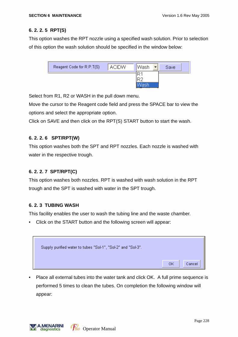
SECTION 6 MAINTENANCE Version 1.6 Rev May 2005
6. 2. 2. 5 RPT(S)
This option washes the RPT nozzle using a specified wash solution. Prior to selection
of this option the wash solution should be specified in the window below:
Select from R1, R2 or WASH in the pull down menu.
Move the cursor to the Reagent code field and press the SPACE bar to view the
options and select the appropriate option.
Click on SAVE and then click on the RPT(S) START button to start the wash.
6. 2. 2. 6 SPT/RPT(W)
This option washes both the SPT and RPT nozzles. Each nozzle is washed with
water in the respective trough.
6. 2. 2. 7 SPT/RPT(C)
This option washes both nozzles. RPT is washed with wash solution in the RPT
trough and the SPT is washed with water in the SPT trough.
6. 2. 3 TUBING WASH
This facility enables the user to wash the tubing line and the waste chamber.
• Click on the START button and the following screen will appear:
• Place all external tubes into the water tank and click OK. A full prime sequence is
performed 5 times to clean the tubes. On completion the following window will
appear:
Page 228
Operator Manual
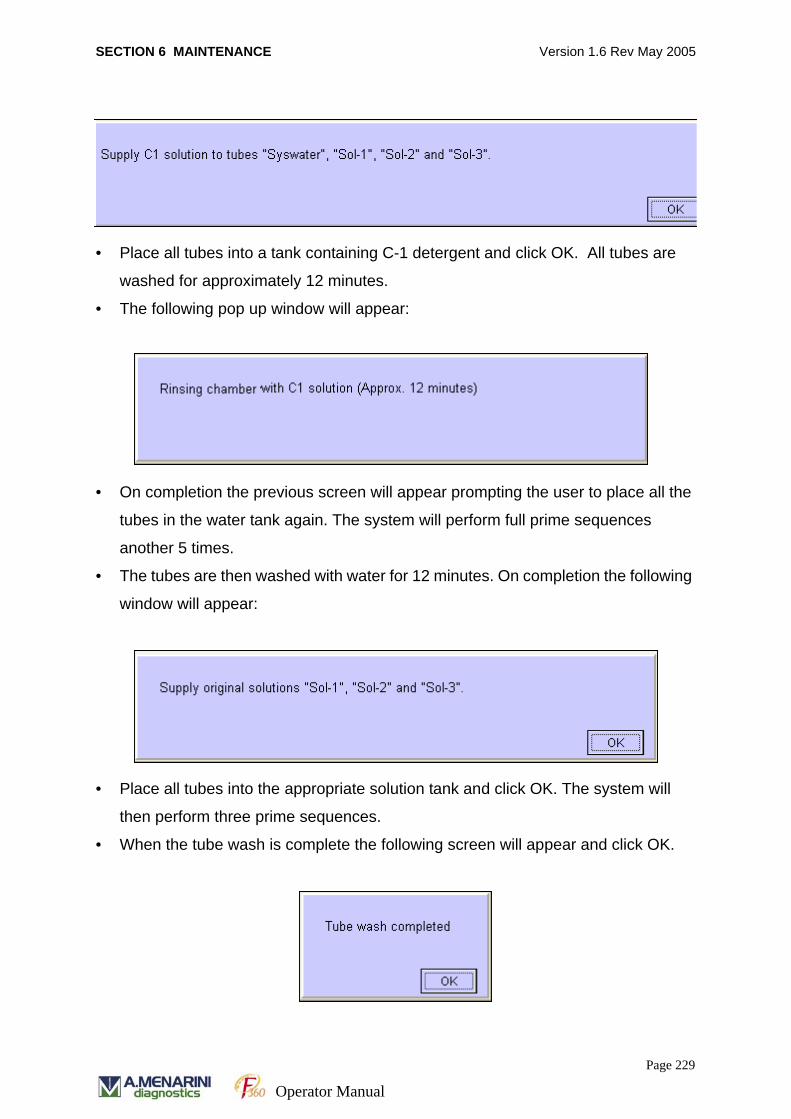
SECTION 6 MAINTENANCE Version 1.6 Rev May 2005
• Place all tubes into a tank containing C-1 detergent and click OK. All tubes are
washed for approximately 12 minutes.
• The following pop up window will appear:
• On completion the previous screen will appear prompting the user to place all the
tubes in the water tank again. The system will perform full prime sequences
another 5 times.
• The tubes are then washed with water for 12 minutes. On completion the following
window will appear:
• Place all tubes into the appropriate solution tank and click OK. The system will
then perform three prime sequences.
• When the tube wash is complete the following screen will appear and click OK.
Page 229
Operator Manual
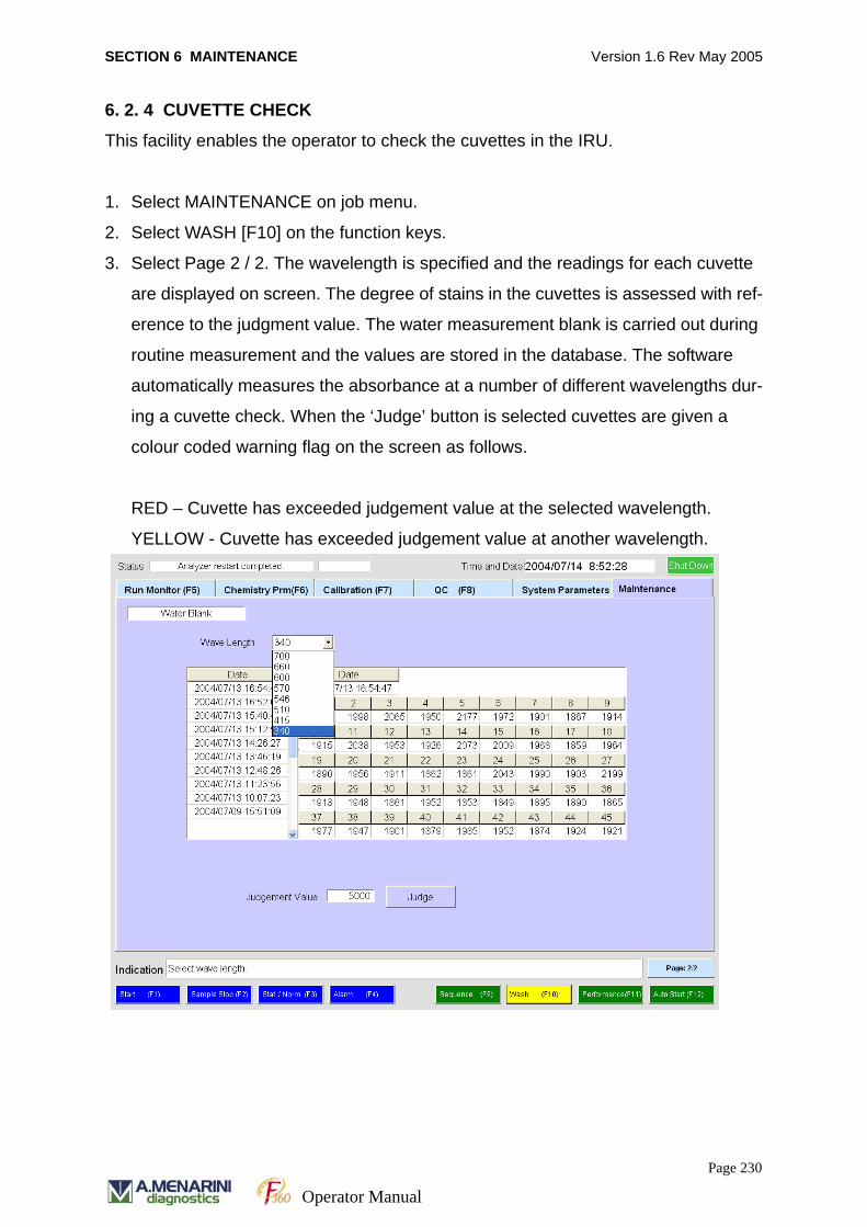
SECTION 6 MAINTENANCE Version 1.6 Rev May 2005
6. 2. 4 CUVETTE CHECK
This facility enables the operator to check the cuvettes in the IRU.
1. Select MAINTENANCE on job menu.
2. Select WASH [F10] on the function keys.
3. Select Page 2 / 2. The wavelength is specified and the readings for each cuvette
are displayed on screen. The degree of stains in the cuvettes is assessed with ref-
erence to the judgment value. The water measurement blank is carried out during
routine measurement and the values are stored in the database. The software
automatically measures the absorbance at a number of different wavelengths dur-
ing a cuvette check. When the ‘Judge’ button is selected cuvettes are given a
colour coded warning flag on the screen as follows.
RED – Cuvette has exceeded judgement value at the selected wavelength.
YELLOW - Cuvette has exceeded judgement value at another wavelength.
Page 230
Operator Manual
SECTION 6 MAINTENANCE Version 1.6 Rev May 2005
6. 2. 4. 1 WAVELENGTH
By specifying the wavelength, the relevant measurement result can be selected. Click
on the scroll bar in the wavelength box and select the required wavelength.
6. 2. 4. 2 DATE (DATE OF MEASUREMENT)
The water blank data obtained from the past measurements can be selected by
specifying the date of measurement. Click on the date of interest.
6. 2. 4. 3 JUDGEMENT VALUE
The maximum accepted value for the water blank at each wavelength.
6. 2. 4. 4 ACCEPTED RESULT
Water blank result for each cuvette (total 45 cuvettes) is compared with the judgment
value as indicated.
If a cuvette water blank measurement exceeds the judgment value, the cuvette will
NOT be used in the next sample run.
6. 2. 5 WORKING HOURS OF EXPENDABLE PARTS
The list of remaining working hours for analyser parts is displayed on the WASH
function screen shown above.
1. Select MAINTENANCE on the job menu.
2. Select WASH [F10] on the function keys.
3. Click on the RESET button after the system part has been changed. The software
will reset the values to the initial values displayed in brackets.
Page 231
Operator Manual
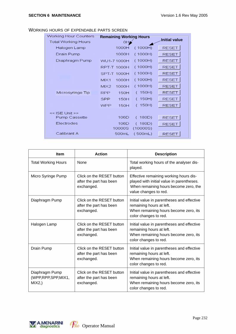
SECTION 6 MAINTENANCE Version 1.6 Rev May 2005
WORKING HOURS OF EXPENDABLE PARTS SCREEN
Item Action Description
Total Working Hours None Total working hours of the analyser dis-played.
Micro Syringe Pump Click on the RESET button after the part has been exchanged.
Effective remaining working hours dis-played with initial value in parentheses.When remaining hours become zero, the value changes to red.
Diaphragm Pump Click on the RESET button after the part has been exchanged.
Initial value in parentheses and effective remaining hours at left.When remaining hours become zero, its color changes to red.
Halogen Lamp Click on the RESET button after the part has been exchanged.
Initial value in parentheses and effective remaining hours at left.When remaining hours become zero, its color changes to red.
Drain Pump Click on the RESET button after the part has been exchanged.
Initial value in parentheses and effective remaining hours at left.When remaining hours become zero, its color changes to red.
Diaphragm Pump(WPP,RPP,SPP,MIX1,MIX2,)
Click on the RESET button after the part has been exchanged.
Initial value in parentheses and effective remaining hours at left.When remaining hours become zero, its color changes to red.
Remaining Working HoursInitial value
Page 232
Operator Manual
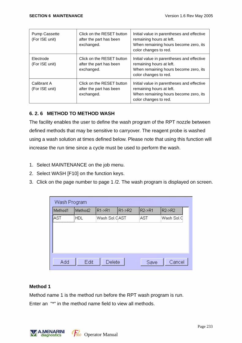
SECTION 6 MAINTENANCE Version 1.6 Rev May 2005
6. 2. 6 METHOD TO METHOD WASH
The facility enables the user to define the wash program of the RPT nozzle between
defined methods that may be sensitive to carryover. The reagent probe is washed
using a wash solution at times defined below. Please note that using this function will
increase the run time since a cycle must be used to perform the wash.
1. Select MAINTENANCE on the job menu.
2. Select WASH [F10] on the function keys.
3. Click on the page number to page 1 /2. The wash program is displayed on screen.
Method 1
Method name 1 is the method run before the RPT wash program is run.
Enter an "*" in the method name field to view all methods.
Pump Cassette(For ISE unit)
Click on the RESET button after the part has been exchanged.
Initial value in parentheses and effective remaining hours at left.When remaining hours become zero, its color changes to red.
Electrode(For ISE unit)
Click on the RESET button after the part has been exchanged.
Initial value in parentheses and effective remaining hours at left.When remaining hours become zero, its color changes to red.
Calibrant A(For ISE unit)
Click on the RESET button after the part has been exchanged.
Initial value in parentheses and effective remaining hours at left.When remaining hours become zero, its color changes to red.
Page 233
Operator Manual
SECTION 6 MAINTENANCE Version 1.6 Rev May 2005
Method 2
Method number 2 is the method run immediately after the RPT wash program has
been run.
The wildcard "*" as the method name means all methods.
R1 → R1
The R1 reagent for the method 2 is dispensed after the R1 reagent for method 1.
The nozzle wash is carried out using the defined wash solution after dispensing R1
for method 1.
R1 → R2
The R2 reagent for the method 2 is dispensed after the R1 reagent for method 1.
The nozzle wash is carried out using the defined wash solution after dispensing R1
for method 1.
R2 → R1
The R1 reagent for the method 2 is dispensed after the R2 reagent for method 1 was
dispensed.
The nozzle wash is carried out using the defined wash solution after dispensing R2
for method 1.
R2 → R2
The R2 reagent for the method 2 is dispensed after the R2 reagent for method 1 was
dispensed.
The nozzle wash is carried out using the defined wash solution after dispensing R2
for method 1.
Add (Addition of program)
Click on this button to add the method-to-method wash program of the RPT nozzle.
Page 234
Operator Manual
SECTION 6 MAINTENANCE Version 1.6 Rev May 2005
Edit (Editing of program)
Click on this button to edit the method-to-method wash program in the list of wash
programs.
Delete (Deletion of program)
Specify the method-to-method wash program in the list of wash programs and click on
this button to delete it.
Cancel
Click on this button to cancel the above addition or edition.
Save
Click on this button to save above addition, edition and deletion of the method-to-
method wash program.
Wash solutions are registered in the [System (F9)] on the job menu [System
Parameters].
This method-to-method wash has precedence over the "RPT wash" specified in the
[Chemistry Prm][Chemistry (F9)].
The detailed procedure for how to structure the method-to-method wash program is
shown below.
How to setup the method-to-method wash program
The method-to-method wash program is created using Add, Edit, Delete, Save and
Cancel buttons.
The following pop-up window appears by clicking on the Add or Edit button.
Page 235
Operator Manual
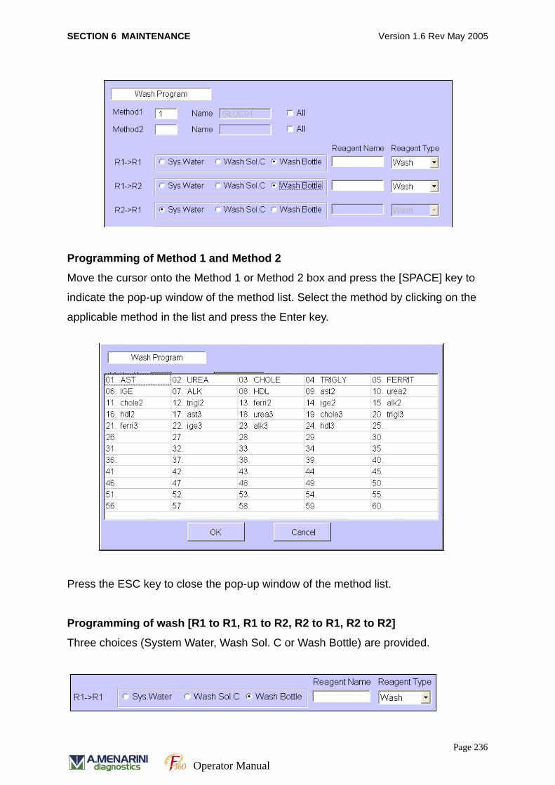
SECTION 6 MAINTENANCE Version 1.6 Rev May 2005
Programming of Method 1 and Method 2
Move the cursor onto the Method 1 or Method 2 box and press the [SPACE] key to
indicate the pop-up window of the method list. Select the method by clicking on the
applicable method in the list and press the Enter key.
Press the ESC key to close the pop-up window of the method list.
Programming of wash [R1 to R1, R1 to R2, R2 to R1, R2 to R2]
Three choices (System Water, Wash Sol. C or Wash Bottle) are provided.
Page 236
Operator Manual
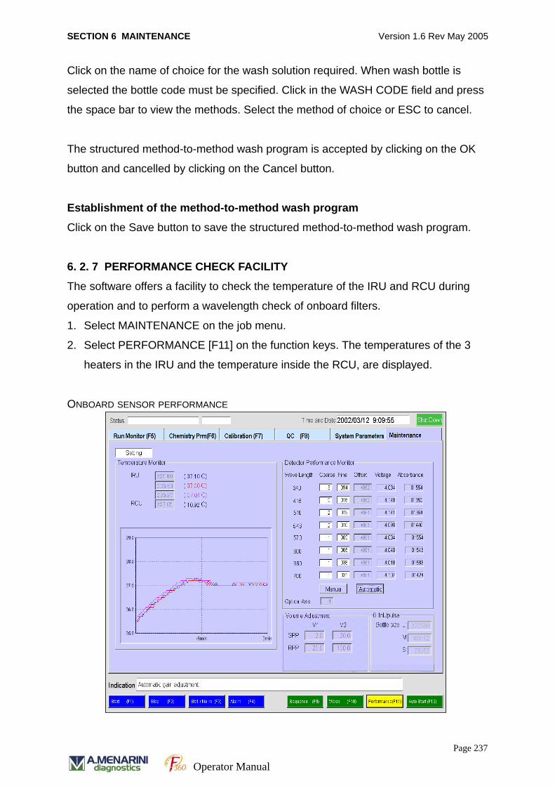
SECTION 6 MAINTENANCE Version 1.6 Rev May 2005
Click on the name of choice for the wash solution required. When wash bottle is
selected the bottle code must be specified. Click in the WASH CODE field and press
the space bar to view the methods. Select the method of choice or ESC to cancel.
The structured method-to-method wash program is accepted by clicking on the OK
button and cancelled by clicking on the Cancel button.
Establishment of the method-to-method wash program
Click on the Save button to save the structured method-to-method wash program.
6. 2. 7 PERFORMANCE CHECK FACILITY
The software offers a facility to check the temperature of the IRU and RCU during
operation and to perform a wavelength check of onboard filters.
1. Select MAINTENANCE on the job menu.
2. Select PERFORMANCE [F11] on the function keys. The temperatures of the 3
heaters in the IRU and the temperature inside the RCU, are displayed.
ONBOARD SENSOR PERFORMANCE
Page 237
Operator Manual
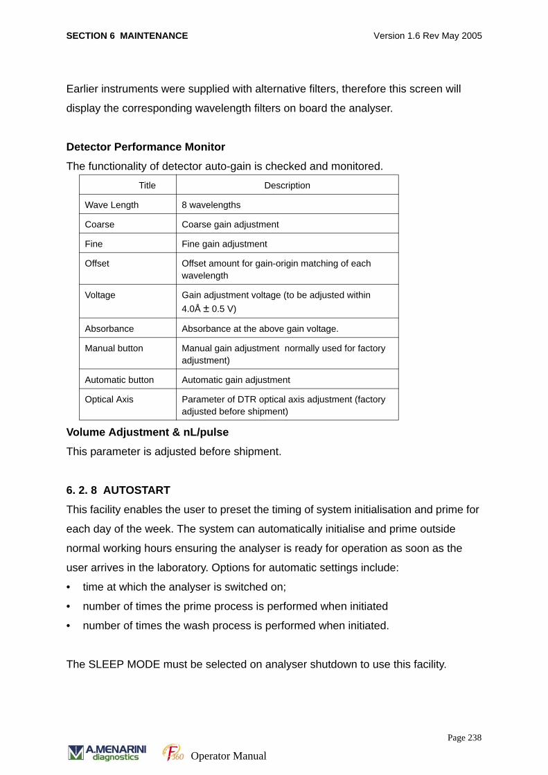
SECTION 6 MAINTENANCE Version 1.6 Rev May 2005
Earlier instruments were supplied with alternative filters, therefore this screen will
display the corresponding wavelength filters on board the analyser.
Detector Performance Monitor
The functionality of detector auto-gain is checked and monitored.
Volume Adjustment & nL/pulse
This parameter is adjusted before shipment.
6. 2. 8 AUTOSTART
This facility enables the user to preset the timing of system initialisation and prime for
each day of the week. The system can automatically initialise and prime outside
normal working hours ensuring the analyser is ready for operation as soon as the
user arrives in the laboratory. Options for automatic settings include:
• time at which the analyser is switched on;
• number of times the prime process is performed when initiated
• number of times the wash process is performed when initiated.
The SLEEP MODE must be selected on analyser shutdown to use this facility.
Title Description
Wave Length 8 wavelengths
Coarse Coarse gain adjustment
Fine Fine gain adjustment
Offset Offset amount for gain-origin matching of each wavelength
Voltage Gain adjustment voltage (to be adjusted within 4.0Å ± 0.5 V)
Absorbance Absorbance at the above gain voltage.
Manual button Manual gain adjustment normally used for factory adjustment)
Automatic button Automatic gain adjustment
Optical Axis Parameter of DTR optical axis adjustment (factory adjusted before shipment)
Page 238
Operator Manual
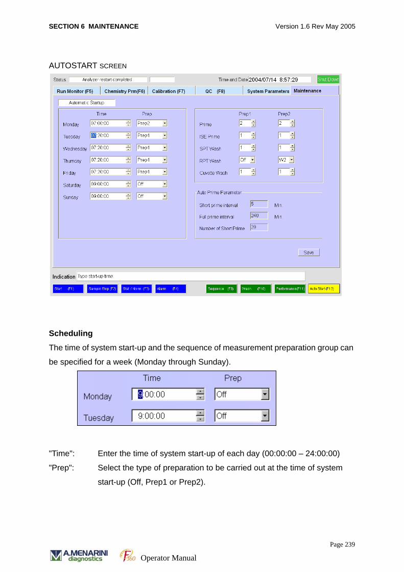
SECTION 6 MAINTENANCE Version 1.6 Rev May 2005
AUTOSTART SCREEN
Scheduling
The time of system start-up and the sequence of measurement preparation group can
be specified for a week (Monday through Sunday).
"Time": Enter the time of system start-up of each day (00:00:00 – 24:00:00)
"Prep": Select the type of preparation to be carried out at the time of system
start-up (Off, Prep1 or Prep2).
Page 239
Operator Manual
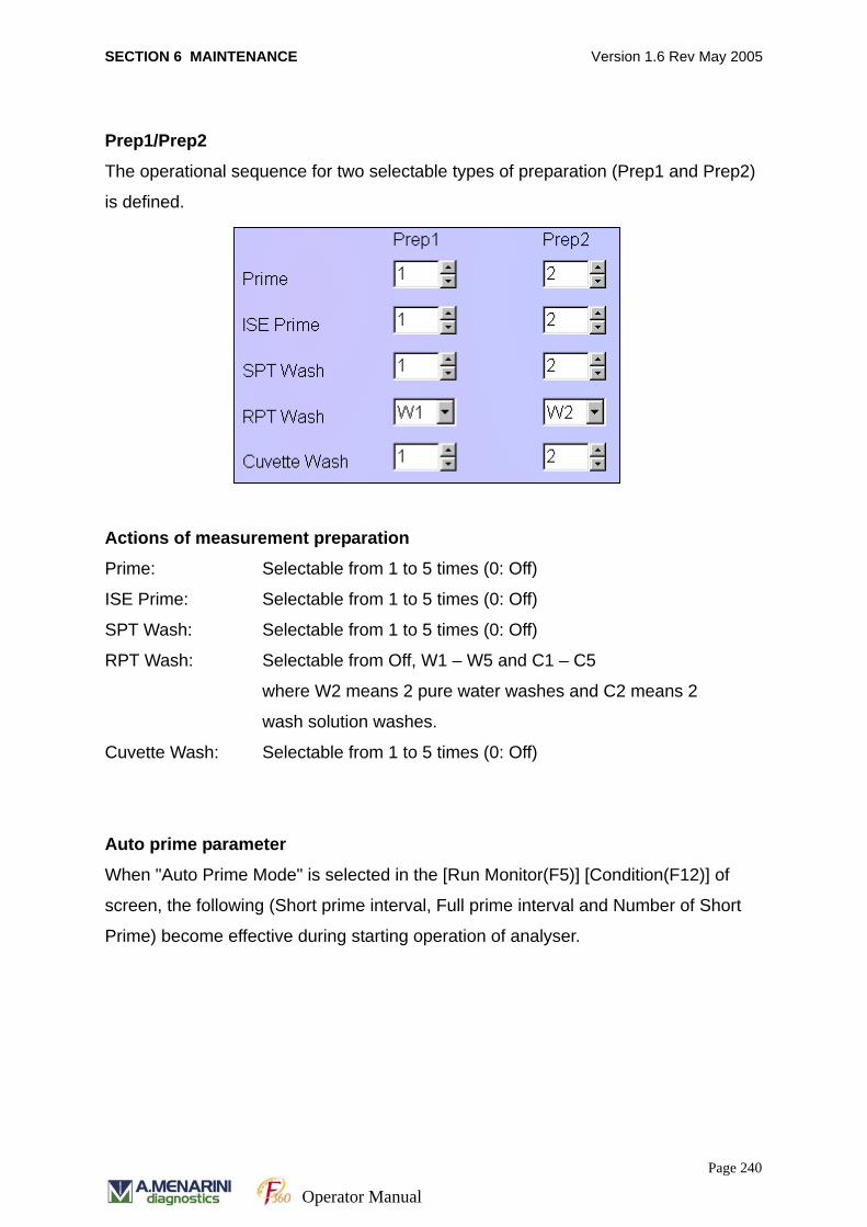
SECTION 6 MAINTENANCE Version 1.6 Rev May 2005
Prep1/Prep2
The operational sequence for two selectable types of preparation (Prep1 and Prep2)
is defined.
Actions of measurement preparation
Prime: Selectable from 1 to 5 times (0: Off)
ISE Prime: Selectable from 1 to 5 times (0: Off)
SPT Wash: Selectable from 1 to 5 times (0: Off)
RPT Wash: Selectable from Off, W1 – W5 and C1 – C5
where W2 means 2 pure water washes and C2 means 2
wash solution washes.
Cuvette Wash: Selectable from 1 to 5 times (0: Off)
Auto prime parameter
When "Auto Prime Mode" is selected in the [Run Monitor(F5)] [Condition(F12)] of
screen, the following (Short prime interval, Full prime interval and Number of Short
Prime) become effective during starting operation of analyser.
Page 240
Operator Manual
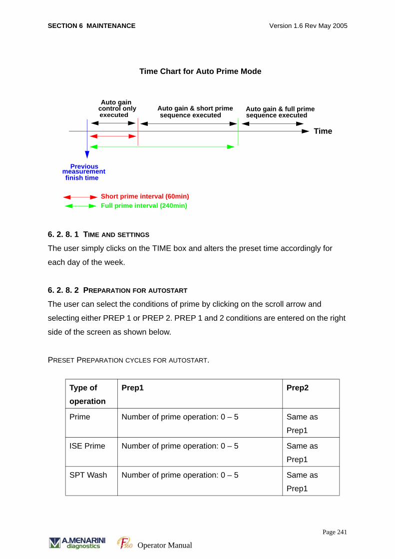
SECTION 6 MAINTENANCE Version 1.6 Rev May 2005
6. 2. 8. 1 TIME AND SETTINGS
The user simply clicks on the TIME box and alters the preset time accordingly for
each day of the week.
6. 2. 8. 2 PREPARATION FOR AUTOSTART
The user can select the conditions of prime by clicking on the scroll arrow and
selecting either PREP 1 or PREP 2. PREP 1 and 2 conditions are entered on the right
side of the screen as shown below.
PRESET PREPARATION CYCLES FOR AUTOSTART.
Type of operation
Prep1 Prep2
Prime Number of prime operation: 0 – 5 Same as
Prep1
ISE Prime Number of prime operation: 0 – 5 Same as
Prep1
SPT Wash Number of prime operation: 0 – 5 Same as
Prep1
Previousfinish time
measurement
Short prime interval (60min)Full prime interval (240min)
Auto gaincontrol only executed
Auto gain & short primesequence executed
Auto gain & full primesequence executed
Time Chart for Auto Prime Mode
Time
Page 241
Operator Manual
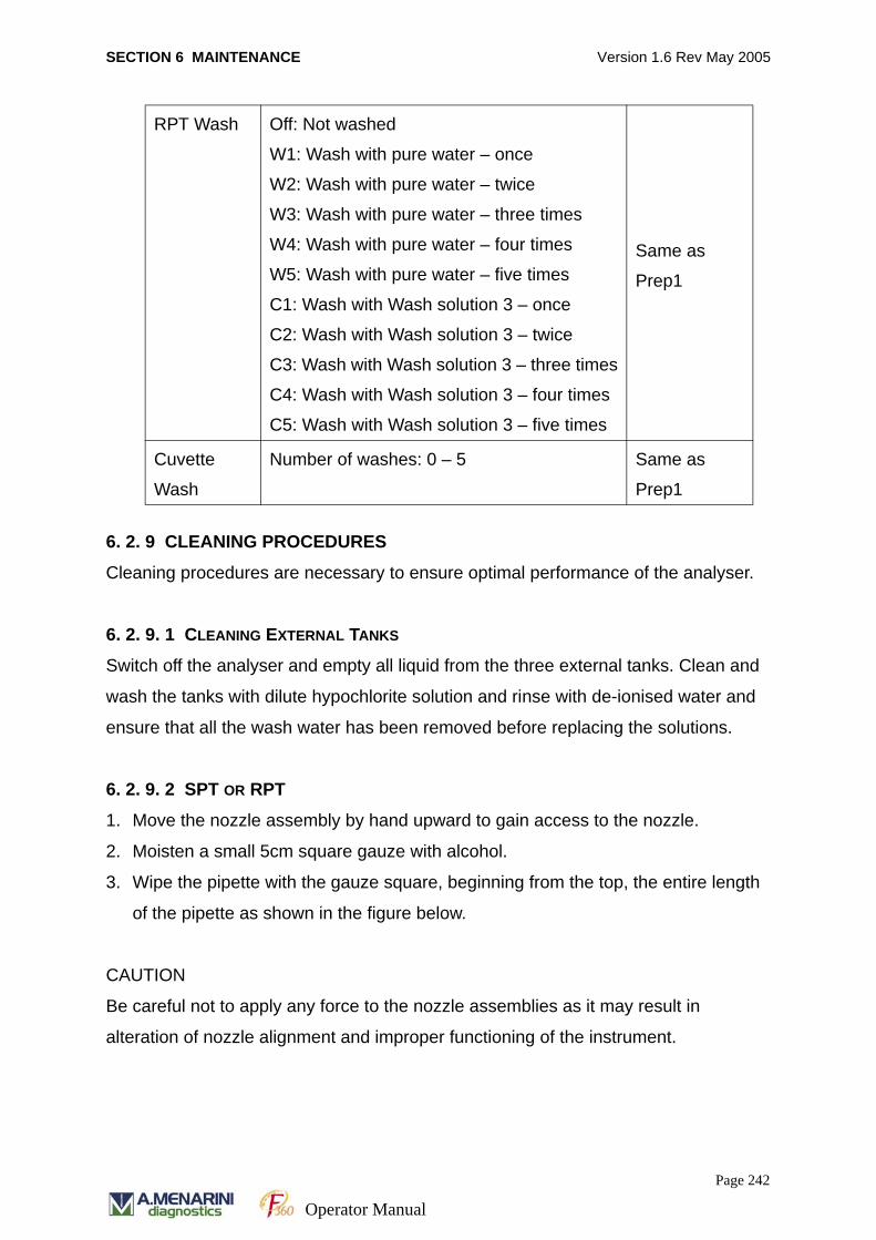
SECTION 6 MAINTENANCE Version 1.6 Rev May 2005
6. 2. 9 CLEANING PROCEDURES
Cleaning procedures are necessary to ensure optimal performance of the analyser.
6. 2. 9. 1 CLEANING EXTERNAL TANKS
Switch off the analyser and empty all liquid from the three external tanks. Clean and
wash the tanks with dilute hypochlorite solution and rinse with de-ionised water and
ensure that all the wash water has been removed before replacing the solutions.
6. 2. 9. 2 SPT OR RPT
1. Move the nozzle assembly by hand upward to gain access to the nozzle.
2. Moisten a small 5cm square gauze with alcohol.
3. Wipe the pipette with the gauze square, beginning from the top, the entire length
of the pipette as shown in the figure below.
CAUTION
Be careful not to apply any force to the nozzle assemblies as it may result in
alteration of nozzle alignment and improper functioning of the instrument.
RPT Wash Off: Not washed
W1: Wash with pure water – once
W2: Wash with pure water – twice
W3: Wash with pure water – three times
W4: Wash with pure water – four times
W5: Wash with pure water – five times
C1: Wash with Wash solution 3 – once
C2: Wash with Wash solution 3 – twice
C3: Wash with Wash solution 3 – three times
C4: Wash with Wash solution 3 – four times
C5: Wash with Wash solution 3 – five times
Same as
Prep1
Cuvette
Wash
Number of washes: 0 – 5 Same as
Prep1
Page 242
Operator Manual
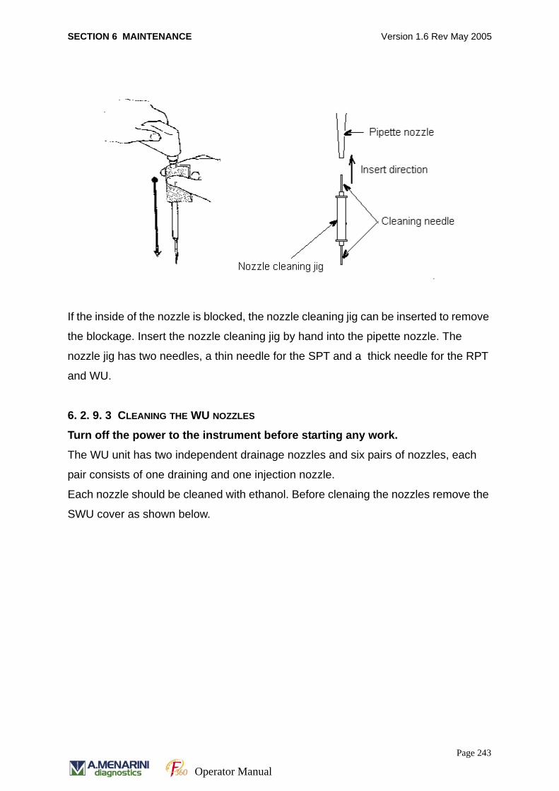
SECTION 6 MAINTENANCE Version 1.6 Rev May 2005
If the inside of the nozzle is blocked, the nozzle cleaning jig can be inserted to remove
the blockage. Insert the nozzle cleaning jig by hand into the pipette nozzle. The
nozzle jig has two needles, a thin needle for the SPT and a thick needle for the RPT
and WU.
6. 2. 9. 3 CLEANING THE WU NOZZLES
Turn off the power to the instrument before starting any work.
The WU unit has two independent drainage nozzles and six pairs of nozzles, each
pair consists of one draining and one injection nozzle.
Each nozzle should be cleaned with ethanol. Before clenaing the nozzles remove the
SWU cover as shown below.
Page 243
Operator Manual
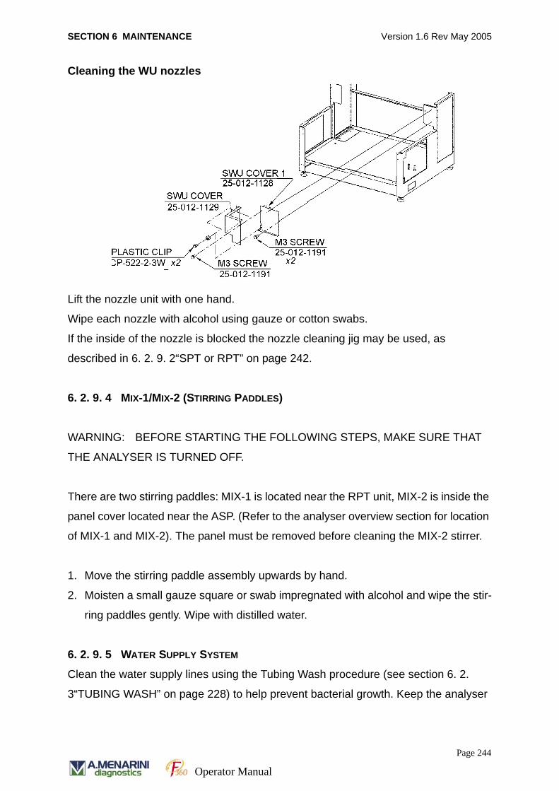
SECTION 6 MAINTENANCE Version 1.6 Rev May 2005
Cleaning the WU nozzles
Lift the nozzle unit with one hand.
Wipe each nozzle with alcohol using gauze or cotton swabs.
If the inside of the nozzle is blocked the nozzle cleaning jig may be used, as
described in 6. 2. 9. 2“SPT or RPT” on page 242.
6. 2. 9. 4 MIX-1/MIX-2 (STIRRING PADDLES)
WARNING: BEFORE STARTING THE FOLLOWING STEPS, MAKE SURE THAT
THE ANALYSER IS TURNED OFF.
There are two stirring paddles: MIX-1 is located near the RPT unit, MIX-2 is inside the
panel cover located near the ASP. (Refer to the analyser overview section for location
of MIX-1 and MIX-2). The panel must be removed before cleaning the MIX-2 stirrer.
1. Move the stirring paddle assembly upwards by hand.
2. Moisten a small gauze square or swab impregnated with alcohol and wipe the stir-
ring paddles gently. Wipe with distilled water.
6. 2. 9. 5 WATER SUPPLY SYSTEM
Clean the water supply lines using the Tubing Wash procedure (see section 6. 2.
3“TUBING WASH” on page 228) to help prevent bacterial growth. Keep the analyser
Page 244
Operator Manual
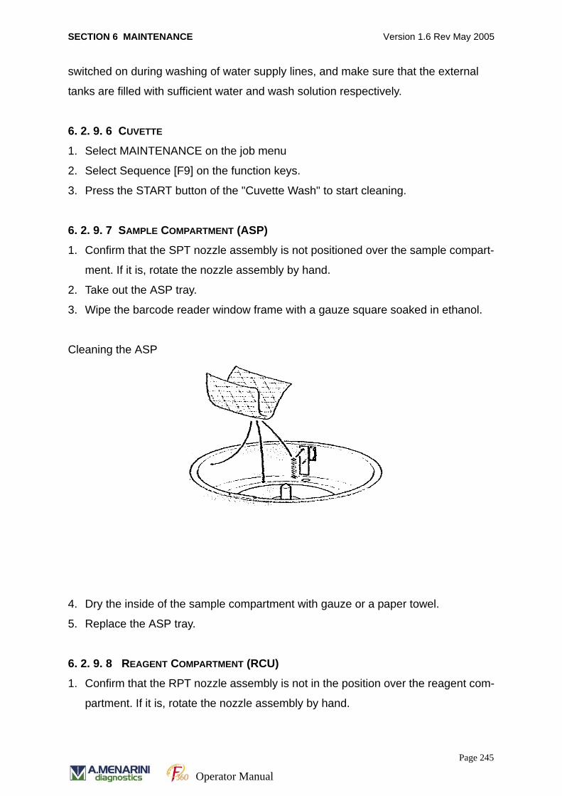
SECTION 6 MAINTENANCE Version 1.6 Rev May 2005
switched on during washing of water supply lines, and make sure that the external
tanks are filled with sufficient water and wash solution respectively.
6. 2. 9. 6 CUVETTE
1. Select MAINTENANCE on the job menu
2. Select Sequence [F9] on the function keys.
3. Press the START button of the "Cuvette Wash" to start cleaning.
6. 2. 9. 7 SAMPLE COMPARTMENT (ASP)
1. Confirm that the SPT nozzle assembly is not positioned over the sample compart-
ment. If it is, rotate the nozzle assembly by hand.
2. Take out the ASP tray.
3. Wipe the barcode reader window frame with a gauze square soaked in ethanol.
Cleaning the ASP
4. Dry the inside of the sample compartment with gauze or a paper towel.
5. Replace the ASP tray.
6. 2. 9. 8 REAGENT COMPARTMENT (RCU)
1. Confirm that the RPT nozzle assembly is not in the position over the reagent com-
partment. If it is, rotate the nozzle assembly by hand.
Page 245
Operator Manual

SECTION 6 MAINTENANCE Version 1.6 Rev May 2005
2. Take out the RCU tray.
Cleaning the RCU
3. Clean the inside of the reagent compartment with gauze or a paper towel as
shown. Make sure that all condensation is removed.
4. Replace the RCU tray and close the lid.
6. 2. 9. 9 MOSAIC PLATE
Clean the surface of the mosaic plates with ethanol moistened gauze or a paper
towel.
Page 246
Operator Manual
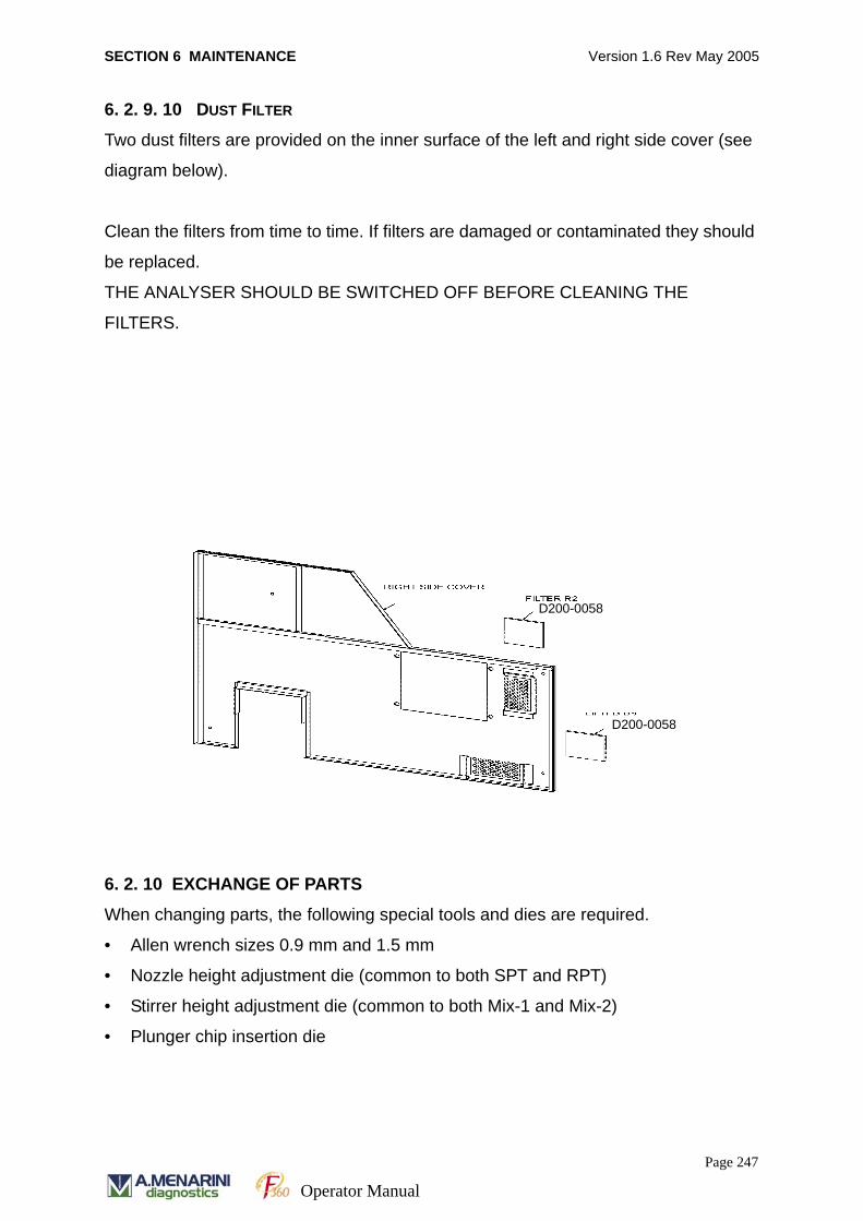
SECTION 6 MAINTENANCE Version 1.6 Rev May 2005
6. 2. 9. 10 DUST FILTER
Two dust filters are provided on the inner surface of the left and right side cover (see
diagram below).
Clean the filters from time to time. If filters are damaged or contaminated they should
be replaced.
THE ANALYSER SHOULD BE SWITCHED OFF BEFORE CLEANING THE
FILTERS.
6. 2. 10 EXCHANGE OF PARTS
When changing parts, the following special tools and dies are required.
• Allen wrench sizes 0.9 mm and 1.5 mm
• Nozzle height adjustment die (common to both SPT and RPT)
• Stirrer height adjustment die (common to both Mix-1 and Mix-2)
• Plunger chip insertion die
D200-0058
D200-0058
Page 247
Operator Manual
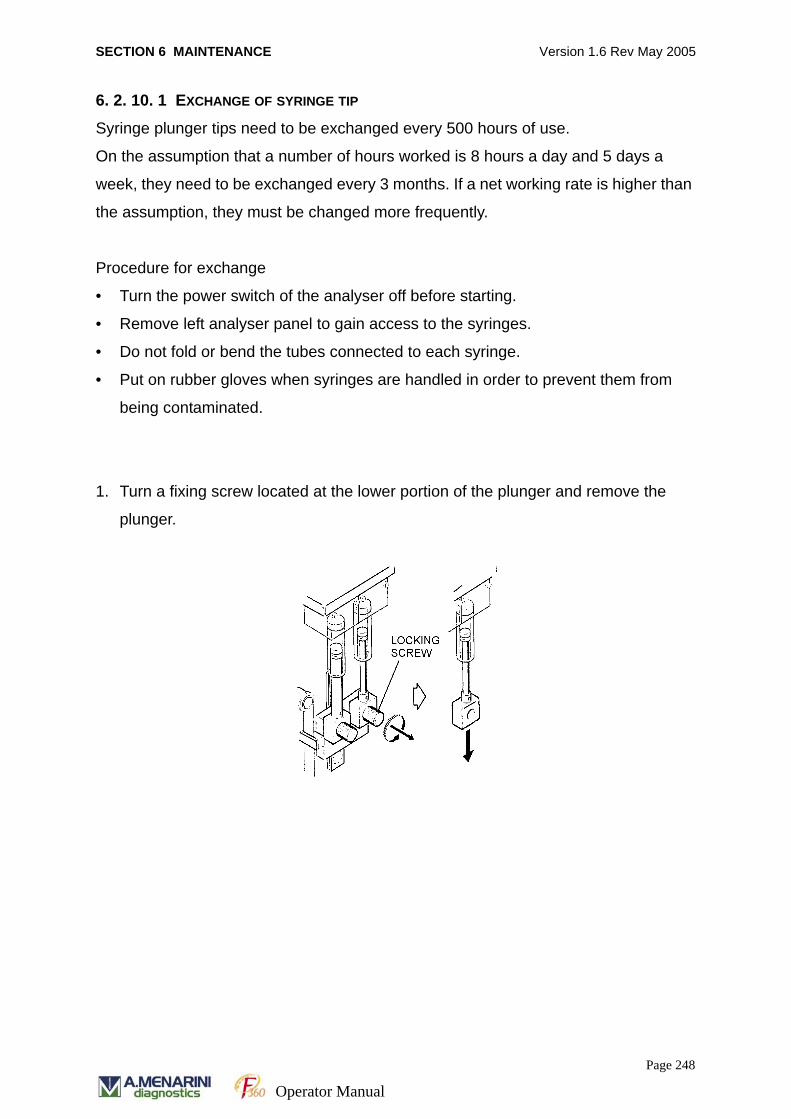
SECTION 6 MAINTENANCE Version 1.6 Rev May 2005
6. 2. 10. 1 EXCHANGE OF SYRINGE TIP
Syringe plunger tips need to be exchanged every 500 hours of use.
On the assumption that a number of hours worked is 8 hours a day and 5 days a
week, they need to be exchanged every 3 months. If a net working rate is higher than
the assumption, they must be changed more frequently.
Procedure for exchange
• Turn the power switch of the analyser off before starting.
• Remove left analyser panel to gain access to the syringes.
• Do not fold or bend the tubes connected to each syringe.
• Put on rubber gloves when syringes are handled in order to prevent them from
being contaminated.
1. Turn a fixing screw located at the lower portion of the plunger and remove the
plunger.
Page 248
Operator Manual
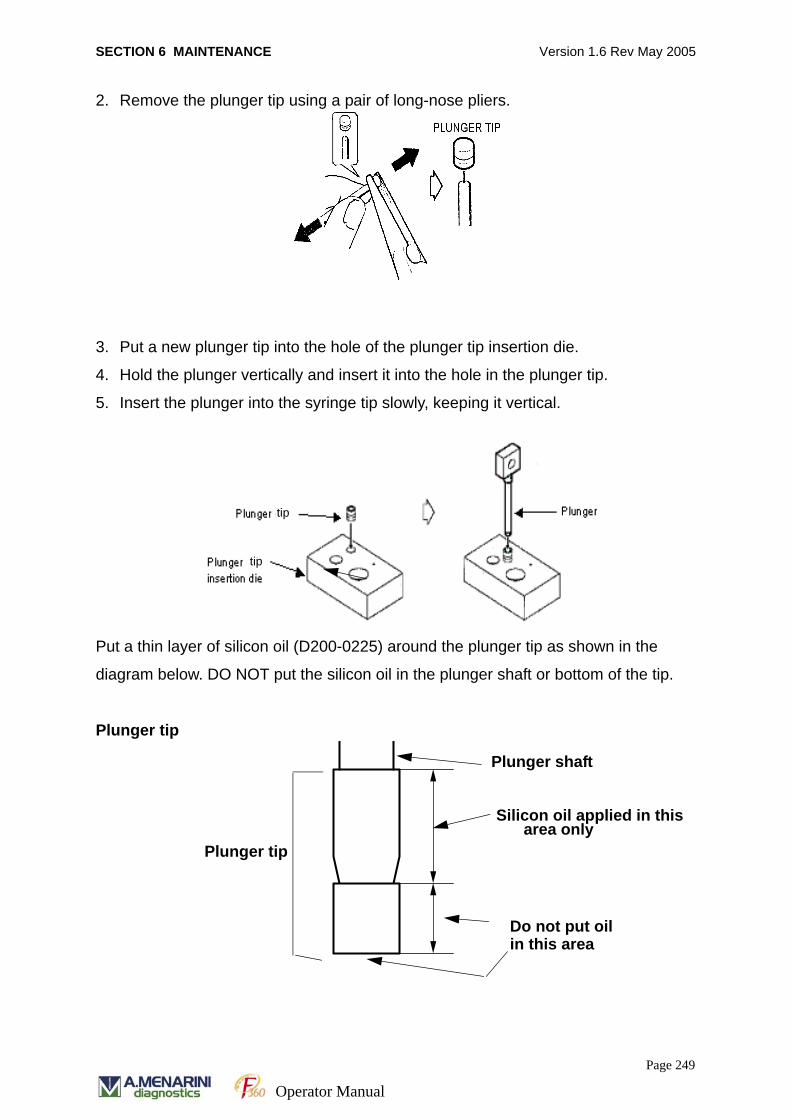
SECTION 6 MAINTENANCE Version 1.6 Rev May 2005
2. Remove the plunger tip using a pair of long-nose pliers.
3. Put a new plunger tip into the hole of the plunger tip insertion die.
4. Hold the plunger vertically and insert it into the hole in the plunger tip.
5. Insert the plunger into the syringe tip slowly, keeping it vertical.
Put a thin layer of silicon oil (D200-0225) around the plunger tip as shown in the
diagram below. DO NOT put the silicon oil in the plunger shaft or bottom of the tip.
Plunger tip
tip
tip
Silicon oil applied in thisarea only
in this area Do not put oil
Plunger shaft
Plunger tip
Page 249
Operator Manual
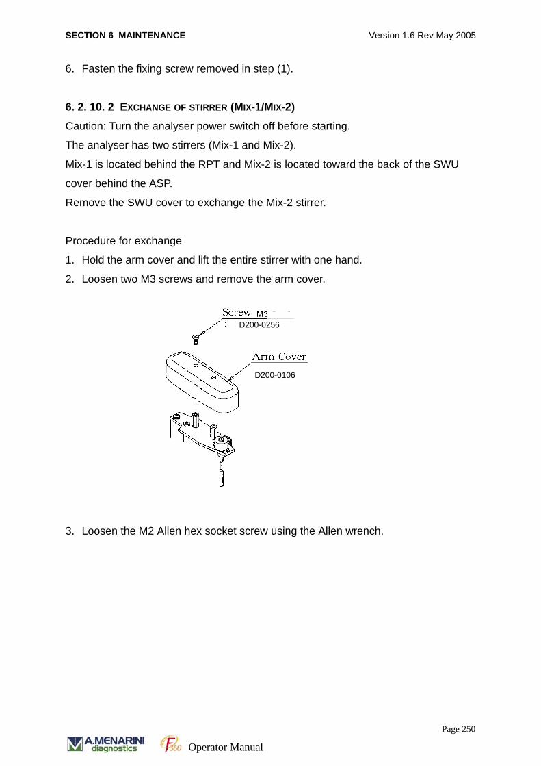
SECTION 6 MAINTENANCE Version 1.6 Rev May 2005
6. Fasten the fixing screw removed in step (1).
6. 2. 10. 2 EXCHANGE OF STIRRER (MIX-1/MIX-2)
Caution: Turn the analyser power switch off before starting.
The analyser has two stirrers (Mix-1 and Mix-2).
Mix-1 is located behind the RPT and Mix-2 is located toward the back of the SWU
cover behind the ASP.
Remove the SWU cover to exchange the Mix-2 stirrer.
Procedure for exchange
1. Hold the arm cover and lift the entire stirrer with one hand.
2. Loosen two M3 screws and remove the arm cover.
3. Loosen the M2 Allen hex socket screw using the Allen wrench.
D200-0256
D200-0106
Page 250
Operator Manual
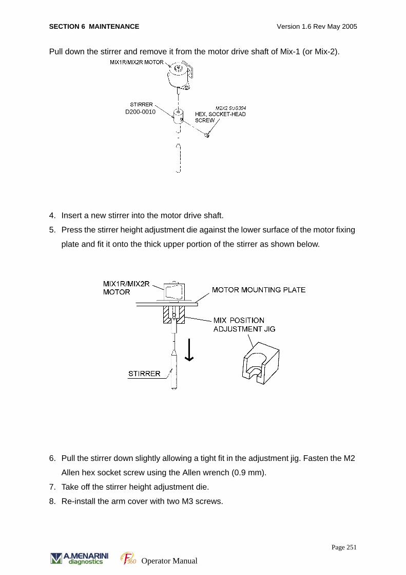
SECTION 6 MAINTENANCE Version 1.6 Rev May 2005
Pull down the stirrer and remove it from the motor drive shaft of Mix-1 (or Mix-2).
4. Insert a new stirrer into the motor drive shaft.
5. Press the stirrer height adjustment die against the lower surface of the motor fixing
plate and fit it onto the thick upper portion of the stirrer as shown below.
6. Pull the stirrer down slightly allowing a tight fit in the adjustment jig. Fasten the M2
Allen hex socket screw using the Allen wrench (0.9 mm).
7. Take off the stirrer height adjustment die.
8. Re-install the arm cover with two M3 screws.
D200-0010
Page 251
Operator Manual
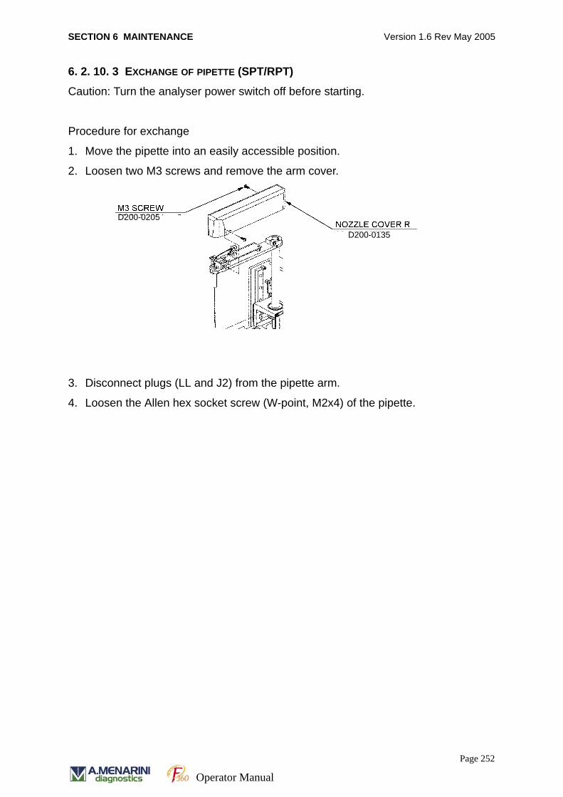
SECTION 6 MAINTENANCE Version 1.6 Rev May 2005
6. 2. 10. 3 EXCHANGE OF PIPETTE (SPT/RPT)
Caution: Turn the analyser power switch off before starting.
Procedure for exchange
1. Move the pipette into an easily accessible position.
2. Loosen two M3 screws and remove the arm cover.
3. Disconnect plugs (LL and J2) from the pipette arm.
4. Loosen the Allen hex socket screw (W-point, M2x4) of the pipette.
D200-0205
D200-0135
Page 252
Operator Manual

SECTION 6 MAINTENANCE Version 1.6 Rev May 2005
5. Remove the pipette nozzle from the pipette arm while the nozzle is lifted up.
6. Remove the tube from the pipette nozzle.
7. Follow the procedure below and install new pipette nozzle.
Adjust the height of the nozzle using the nozzle position adjustment jig.
(a) Cover the nozzle with the nozzle position adjustment jig so that the top
of the jig hits against the lower surface of the nozzle plate and the tip of the
nozzle touches the bottom of the jig.
(b) Push the nozzle down.
(c) Fix the nozzle by fastening the Allen hex socket screw (W-point, M2x4)
using the Allen wrench (0.9 mm).
(d) Make sure that the nozzle moves up and down smoothly.
The nozzle needs to move up and down smoothly in order for the lower limit
sensor to operate properly. This occurs when the tip of the nozzle hits the
bottom of the reagent bottle or sample tube.
D200-0139
D200-0125
Page 253
Operator Manual
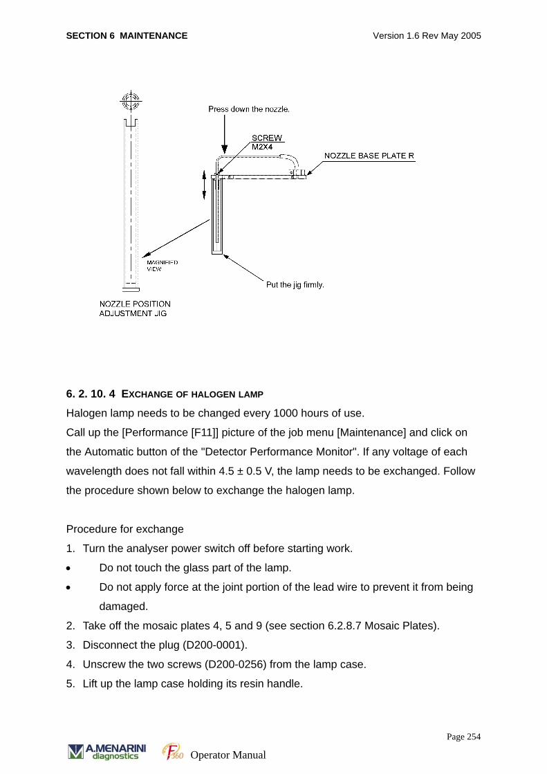
SECTION 6 MAINTENANCE Version 1.6 Rev May 2005
6. 2. 10. 4 EXCHANGE OF HALOGEN LAMP
Halogen lamp needs to be changed every 1000 hours of use.
Call up the [Performance [F11]] picture of the job menu [Maintenance] and click on
the Automatic button of the "Detector Performance Monitor". If any voltage of each
wavelength does not fall within 4.5 ± 0.5 V, the lamp needs to be exchanged. Follow
the procedure shown below to exchange the halogen lamp.
Procedure for exchange
1. Turn the analyser power switch off before starting work.
• Do not touch the glass part of the lamp.
• Do not apply force at the joint portion of the lead wire to prevent it from being
damaged.
2. Take off the mosaic plates 4, 5 and 9 (see section 6.2.8.7 Mosaic Plates).
3. Disconnect the plug (D200-0001).
4. Unscrew the two screws (D200-0256) from the lamp case.
5. Lift up the lamp case holding its resin handle.
Page 254
Operator Manual
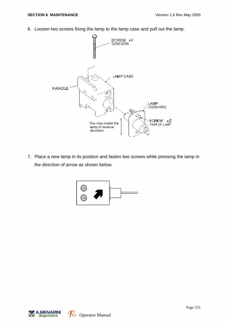
SECTION 6 MAINTENANCE Version 1.6 Rev May 2005
6. Loosen two screws fixing the lamp to the lamp case and pull out the lamp.
7. Place a new lamp in its position and fasten two screws while pressing the lamp in
the direction of arrow as shown below.
D200-0001
D200-0256
Page 255
Operator Manual
SECTION 6 MAINTENANCE Version 1.6 Rev May 2005
Page 256
Operator Manual

SECTION 7 TROUBLESHOOTING Version 1.6 Rev May 2005
SECTION 7
TROUBLESHOOTING
Page 257
Operator Manual
SECTION 7 TROUBLESHOOTING Version 1.6 Rev May 2005
7.1 TROUBLESHOOTINGWhen troubleshooting the F360 the following initial checks should be carried out:
• Preparation and storage of reagent
• Preparation and storage of sample
• Operational method of equipment
• System maintenance
Please contact A. MENARINI Diagnostics Technical Support department if electrical
or mechanical system faults are identified. For safety reasons the user should NOT
carry out internal inspections of the analyser.
7. 1. 1 ANALYTICAL PROBLEMS
When contacting our Technical Support department for troubleshooting problems
please have the following information available.
• Analyser serial number
• Details of the Method code
• Explanation of the problem
• Serial number and lot number of reagent, calibrator and quality control sample
used
• Recent results of calibrations
• Recent results of quality control samples
• Measurement results.
7. 1. 2 EQUIPMENT PROBLEMS
• Serial number
• Software version number in use
• Explanation of the problem and details of relevant alarm codes
• Any other information about equipment or maintenance.
Page 258
Operator Manual
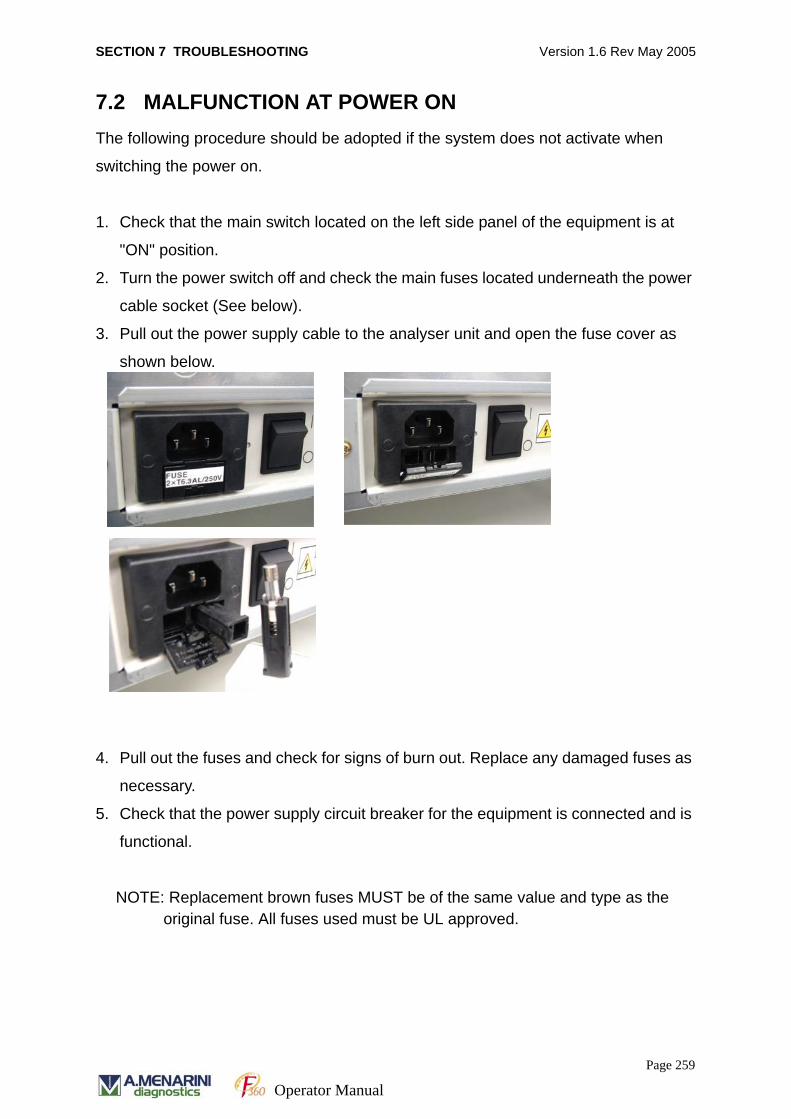
SECTION 7 TROUBLESHOOTING Version 1.6 Rev May 2005
7.2 MALFUNCTION AT POWER ON The following procedure should be adopted if the system does not activate when
switching the power on.
1. Check that the main switch located on the left side panel of the equipment is at
"ON" position.
2. Turn the power switch off and check the main fuses located underneath the power
cable socket (See below).
3. Pull out the power supply cable to the analyser unit and open the fuse cover as
shown below.
4. Pull out the fuses and check for signs of burn out. Replace any damaged fuses as
necessary.
5. Check that the power supply circuit breaker for the equipment is connected and is
functional.
NOTE: Replacement brown fuses MUST be of the same value and type as the original fuse. All fuses used must be UL approved.
Page 259
Operator Manual
SECTION 7 TROUBLESHOOTING Version 1.6 Rev May 2005
7.3 ANOMALOUS RESULTSAnalytical errors may be identified by on screen error flags or the appearance of
unexpected results. Error flags may appear for calibration results, quality control
sample results or normal sample results.
When anomalous results appear, assess the source of the problem by checking the
reagents, calibration samples and quality control samples. Then determine the
following:
• Are the anomalous results high in a specific method for all samples?
• Are the anomalous results low in a specific method for all samples?
• Are anomalous results random?
• Are there two or more anomalous measurement results for all methods or is there
no pattern to the erroneous results?
7. 3. 1 CHECK REAGENTS, CALIBRATORS, QC AND PATIENT SAMPLES
The following checks should be initiated to determine the cause of high, low or
random anomalous results.
• Storage, preparation and use of reagents, calibrators and QC samples adhere to
the manufacturer’s recommendations.
• The reagent has not expired.
• The control and calibrator samples have been prepared according to the manufac-
turer’s recommendations.
• Patient samples do not contain fibrin and blood cells. They should be removed
prior to analysis.
• Serum is not haemolysed, icteric or lipaemic.
• Evaporation has not caused sample concentration.
• Bubbles in the reagents or patient samples may affect aspiration volume.
• Routine system maintenance is up to date.
Page 260
Operator Manual
SECTION 7 TROUBLESHOOTING Version 1.6 Rev May 2005
Preparation of reagent
• Was there any change of reagent?
• Is the on board stability of the prepared reagent still valid?
• Was the reagent prepared according to the correct procedures?
• Is the expiry of the reagent lot still valid?
• Was the reagent prepared using fresh, non-bacteria contaminated and deionised
water or appropriate diluent?
• Has the reagent been scanned.
Preparation of QC sample
• Was the volume used for preparation correct?
• Has the sample been preserved as recommended?
• Is the stability of the sample still valid?
• Was the sample prepared using a calibrated pipette?
• Is the expiry of the control lot still valid?
• Was the sample prepared using appropriate diluents?
Preparation of calibrator
• Was there any change of the lot number?
• Was the calibrator prepared using the correct volume?
• Has the calibrator been preserved as recommended?
• Is the stability period of the calibrator still valid?
• Was the calibrator prepared using a calibrated pipette?
• Is the expiry of the calibrator lot still valid?
• Was the calibrator prepared using appropriate diluents?
For further investigation, refer to the following list after the above checks have been
completed.
Page 261
Operator Manual

SECTION 7 TROUBLESHOOTING Version 1.6 Rev May 2005
7. 3. 2 HIGH VALUES
7. 3. 3 LOW VALUES
Cause Action
1. Incorrect calibration Check the preparation of standard/calibration sample.
Check that the settings of calibration are correct. The
calibration should be repeated.
2. Incubation temperature
too high
Check the temperature indicated on the [Run Moni-
tor] Call customer service department when the indi-
cated temperature deviates from 37 ± 0.5ºC.
3. Improper preparation of
reagent
Check the preparation of reagent according to the
manufacturer’s recommendations.
4. Improper preparation of
standard sample
Check the preparation of standard sample according
to the manufacturer’s recommendations.
Cause Action
1. Reagent expired Check the expiry date of the reagents.
2. Improper reagent
preparation
Check the preparation of reagent.
3. Improper reagent storage Check the recommendations for storage condi-
tions.
4. Incubation temperature
too low
Check the temperature indicated on the [Run
Monitor] Call customer service department when
the indicated temperature deviates from 37 ±
0.5ºC.
5. Improper preparation of
calibration material
Check the preparation of calibration material.
7. Excessive volume of
sampled reagent
Check if there is any leakage at junction of
reagent sampling system.
Page 262
Operator Manual
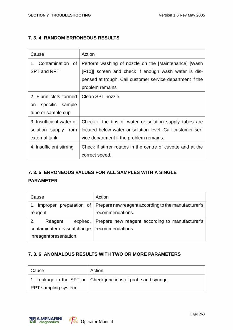
SECTION 7 TROUBLESHOOTING Version 1.6 Rev May 2005
7. 3. 4 RANDOM ERRONEOUS RESULTS
7. 3. 5 ERRONEOUS VALUES FOR ALL SAMPLES WITH A SINGLE
PARAMETER
7. 3. 6 ANOMALOUS RESULTS WITH TWO OR MORE PARAMETERS
Cause Action
1. Contamination of
SPT and RPT
Perform washing of nozzle on the [Maintenance] [Wash
[F10]] screen and check if enough wash water is dis-
pensed at trough. Call customer service department if the
problem remains
2. Fibrin clots formed
on specific sample
tube or sample cup
Clean SPT nozzle.
3. Insufficient water or
solution supply from
external tank
Check if the tips of water or solution supply tubes are
located below water or solution level. Call customer ser-
vice department if the problem remains.
4. Insufficient stirring Check if stirrer rotates in the centre of cuvette and at the
correct speed.
Cause Action
1. Improper preparation ofreagent
Prepare new reagent according to the manufacturer’srecommendations.
2. Reagent expired,contaminated or visual changein reagent presentation.
Prepare new reagent according to manufacturer’srecommendations.
Cause Action
1. Leakage in the SPT or
RPT sampling system
Check junctions of probe and syringe.
Page 263
Operator Manual
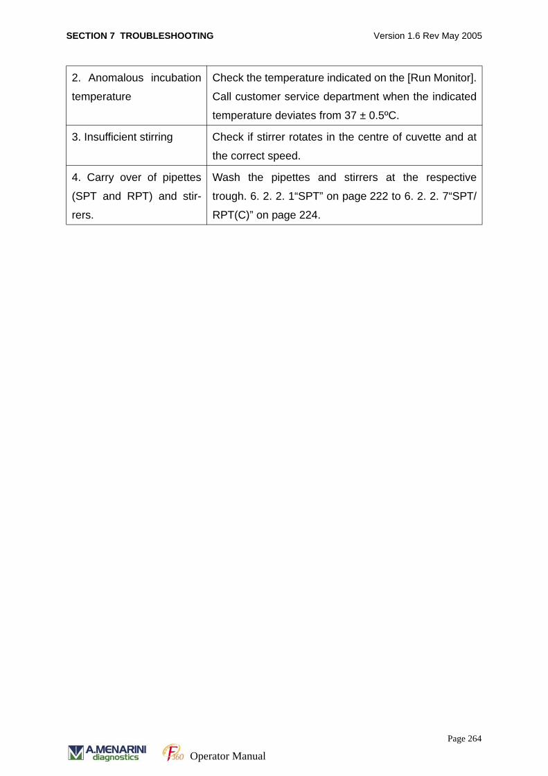
SECTION 7 TROUBLESHOOTING Version 1.6 Rev May 2005
2. Anomalous incubation
temperature
Check the temperature indicated on the [Run Monitor].
Call customer service department when the indicated
temperature deviates from 37 ± 0.5ºC.
3. Insufficient stirring Check if stirrer rotates in the centre of cuvette and at
the correct speed.
4. Carry over of pipettes
(SPT and RPT) and stir-
rers.
Wash the pipettes and stirrers at the respective
trough. 6. 2. 2. 1“SPT” on page 222 to 6. 2. 2. 7“SPT/
RPT(C)” on page 224.
Page 264
Operator Manual
SECTION 7 TROUBLESHOOTING Version 1.6 Rev May 2005
7.4 EQUIPMENT MALFUNCTIONTroubleshooting equipment malfunction is not recommended except in the cases
described below. If equipment problems arise that are not specified here, please
contact the Technical Support department. DO NOT attempt to perform mechanical or
electrical alterations to the analyser.
Page 265
Operator Manual
SECTION 7 TROUBLESHOOTING Version 1.6 Rev May 2005
7.5 MECHANICAL PROBLEMSAll mechanical system checks may be initiated using the software functions. If a
problem arises, the software will specify the source of the problem and visual alarms
are presented on screen.
If a problem arises that may affect the equipment performance, all sampling should
be stopped using the emergency stop action described in this manual. When
sampling stop mode is initiated the equipment will complete the processing steps of
samples that have already been aspirated.
Mechanical problems that are not controlled by the software will not appear on screen
as an error message. This would include problems such as abrasion of parts, leakage
in the sampling system, etc. If this happens, decide whether sample processing
should proceed or whether the measurement should be terminated based on the
possibility of damage to the equipment.
The equipment generates two types of error messages. They are result-related flags
and equipment alarms.
Page 266
Operator Manual
SECTION 7 TROUBLESHOOTING Version 1.6 Rev May 2005
7.6 RESULTS FLAGSWhen the measurement result of a sample is higher or lower than the defined value,
the appropriate flag is printed out together with the measurement result.
7. 6. 1 RESULTS OUTSIDE THE SPECIFIED RANGE
Results are printed out together with the result flags according to the following list.
No Flag Cause Action
1 H
(Higher than upper
limit of normal range)
The measurement
result is above the
specified normal range.
User information only.
2 L
(Lower than lower
limit of normal range)
The measurement
result is below the
specified normal range.
User information only.
3 > The measurement
result is above the tech-
nical range.
User information only.
4 < The measurement
result is below the tech-
nical range.
User information only.
5 r Result from re-run
Page 267
Operator Manual
SECTION 7 TROUBLESHOOTING Version 1.6 Rev May 2005
7.7 ERROR FLAGSResults are printed out with error flags shown in the following list. See error codes in
section 5.4“RESULTS FLAGS AND ERROR FLAGS” on page 200.
No. Flag Cause Action
1. SS Tip of the SPT hits the bottom of tube or cup at the time of aspiration of sample at the ASP unit. (Sample could not be aspirated.)
Check the sample volume in the sample tube or sample cup.
2. SI1 Tip of the SPT hits the bottom of cuvette at the time of dispensation of sample at the IRU. (Sample could not be dispensed.)
Check the level sensor and its associ-ated parts.
3. SI2 Tip of the SPT hits the bottom of cuvette at the time of dispensation of diluent at the IRU. (Diluent could not be dispensed.)
Check the level sensor and its associ-ated parts.
4. R1S Tip of the RPT hits the bottom of cuvette at the time of aspiration of R1 at the RCU. (Shortage of R1 reagent)
Check the volume of R1 reagent in its bottle.
5. R2S Tip of the RPT hits the bottom of cuvette of cuvette at the time of aspira-tion of R2 at the RCU. (Shortage of R2 reagent)
Check the volume of R2 reagent in its bottle.
6. DS Tip of the RPT hits the bottom at the time of aspiration of diluent at the RCU. (Shortage of diluent)
Check the volume of diluent in its bottle.
7. WS Tip of the RPT hits the bottom of cuvette at the time of aspiration of wash solution at the RCU. (Shortage of wash solution)
Check the volume of wash solution in its bottle.
8. TE1 Inside temperature of the IRU is lower than 37ºC.
Check the IRU unit.
9. TE2 Inside temperature of the IRU is higher than 37ºC.
Check the IRU unit.
10. TE3 Inside temperature of the RCU is higher than 15ºC.
Check the RCU unit.
11. R1B R1 reagent bottle has not been regis-tered.
Check that the bar code on the label is a registered reagent on [System Parame-ters][System] screen
12. R2B R2 reagent bottle has not been regis-tered.
Check that the bar code on the label is a registered reagent on [System Parame-ters][System] screen
Page 268
Operator Manual
SECTION 7 TROUBLESHOOTING Version 1.6 Rev May 2005
13. DB Diluent bottle has not been registered. Check that the bar code on the label is a registered reagent on [System Parame-ters][System] screen
14. WB Wash solution bottle has not been reg-istered.
Check that the bar code on the label is a registered reagent on [System Parame-ters][System] screen
15. IE1 No response from ISE unit to sampling start command.
Check the ISE unit.
16. IE2 No measurement result is sent from ISE unit.
Check the ISE unit.
17. EST Error arises during run and sampling is interrupted.
Check the error number.
18. LOT Mismatch of R1 and R2 lot numbers Check R1 & R2 lot numbers
19. R1W RPT wash between methods fails. (Timing of R1)
Repeat affected results
20. R2W RPT wash between methods fails. (Timing of R2)
Repeat affected results
21. EXP Term of validity of reagent has expired. Replace the reagent.
22. STB Term of validity of reagent stability has expired.
Replace the reagent.
23. SPW SPT wash has failed Check the relevant alarm
24. CTO Calibration has expired Run a new calibration for the test and re-apply to the measurement.
25. DUP Variation in calibration results exceeds allowable range. (Variation in duplicate and triplicate measurement results)
Repeat Calibration. If flag obtained again, contact A. MENARINI Diagnos-tics Technical Support
26. SEN Difference in absorbance between Std(min) and STD(max) is out of allow-able range for the calibration measure-ment.
Repeat Calibration. If flag obtained again, contact A. MENARINI Diagnos-tics Technical Support
27. CAL Calibration measurement failed. Repeat Calibration. If flag obtained again, contact A. MENARINI Diagnos-tics Technical Support
28. CA? Unable to calculate results. Repeat Calibration. If flag obtained again, contact A. MENARINI Diagnos-tics Technical Support
29. OVR Concentration is outside the valid cali-bration range.
Sample should be diluted and re-run if automatic re-run is not enabled.
30. LIN Linearity exceeds of allowable limit. Sample should be diluted and re-run if automatic re-run is not enabled.
31. PRO Exceeds prozone limit. Sample should be diluted and re-run if automatic re-run is not enabled.
Page 269
Operator Manual
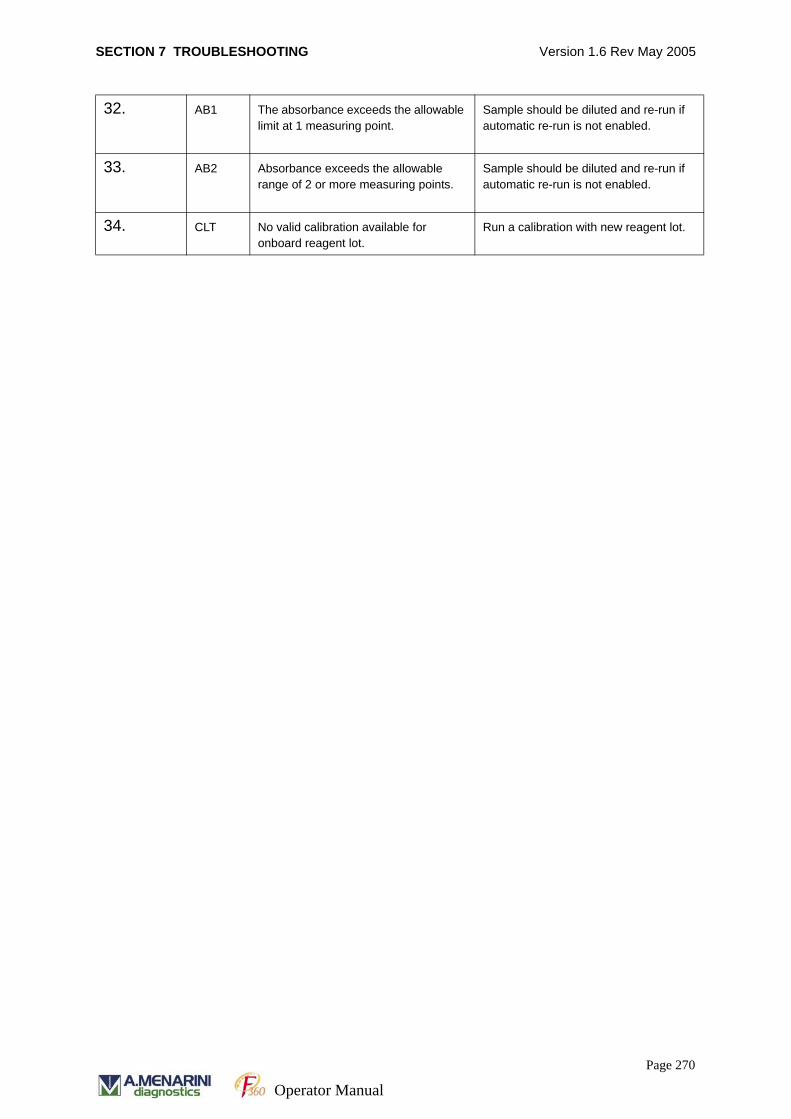
SECTION 7 TROUBLESHOOTING Version 1.6 Rev May 2005
32. AB1 The absorbance exceeds the allowable limit at 1 measuring point.
Sample should be diluted and re-run if automatic re-run is not enabled.
33. AB2 Absorbance exceeds the allowable range of 2 or more measuring points.
Sample should be diluted and re-run if automatic re-run is not enabled.
34. CLT No valid calibration available for onboard reagent lot.
Run a calibration with new reagent lot.
Page 270
Operator Manual
SECTION 7 TROUBLESHOOTING Version 1.6 Rev May 2005
7.8 5-MINUTE TROUBLESHOOTING GUIDE
How can you save hours, even days of problem solving time in just 5 minutes?
When you have a problem:
In the first instance you will have checked alarm codes against chapter 9 in your
Operators Manual and referred to the 'Trouble Shooting Guide'.
Often a quick phone call to our F360 support staff will be sufficient to solve the
problem immediately.
However if our F360 support staff don't know your programme settings, callibration
data and QC results it can make it very difficult to understand how to solve the
problem.
It takes only 5 minutes to collect the data and the following 6 points will help us to find
the solution for you quickly.
7. 8. 1 1. PROGRAM SETTINGS
Please forward a copy of the analyser program screen with every query to enable A.
MENARINI Diagnostics to check the settings.
• Select CHEMISTRY PRM / CHEMISTRY from the menu options to display the
program screen.
• Press CONTROL and F5 to print a copy of the screen to the printer. Then fax the
information to A. MENARINI Diagnostics technical support.
• To email a copy of the program settings follow the instructions below.
To send a copy by e-mail
• Select the screen as described above and press the PRINT SCREEN button
• Click on the Windows START button and and navigate to programs, accessories,
and then the paint program.
Page 271
Operator Manual
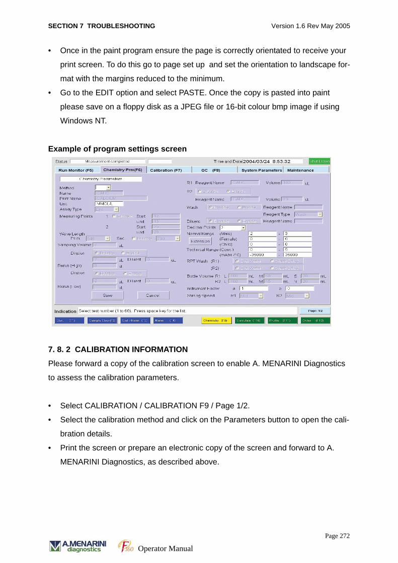
SECTION 7 TROUBLESHOOTING Version 1.6 Rev May 2005
• Once in the paint program ensure the page is correctly orientated to receive your
print screen. To do this go to page set up and set the orientation to landscape for-
mat with the margins reduced to the minimum.
• Go to the EDIT option and select PASTE. Once the copy is pasted into paint
please save on a floppy disk as a JPEG file or 16-bit colour bmp image if using
Windows NT.
Example of program settings screen
7. 8. 2 CALIBRATION INFORMATION
Please forward a copy of the calibration screen to enable A. MENARINI Diagnostics
to assess the calibration parameters.
• Select CALIBRATION / CALIBRATION F9 / Page 1/2.
• Select the calibration method and click on the Parameters button to open the cali-
bration details.
• Print the screen or prepare an electronic copy of the screen and forward to A.
MENARINI Diagnostics, as described above.
Page 272
Operator Manual
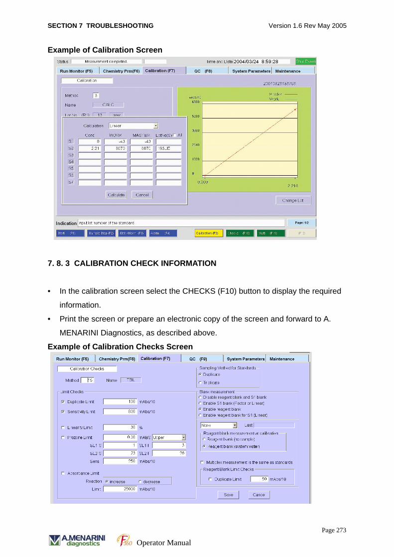
SECTION 7 TROUBLESHOOTING Version 1.6 Rev May 2005
Example of Calibration Screen
7. 8. 3 CALIBRATION CHECK INFORMATION
• In the calibration screen select the CHECKS (F10) button to display the required
information.
• Print the screen or prepare an electronic copy of the screen and forward to A.
MENARINI Diagnostics, as described above.
Example of Calibration Checks Screen
Page 273
Operator Manual
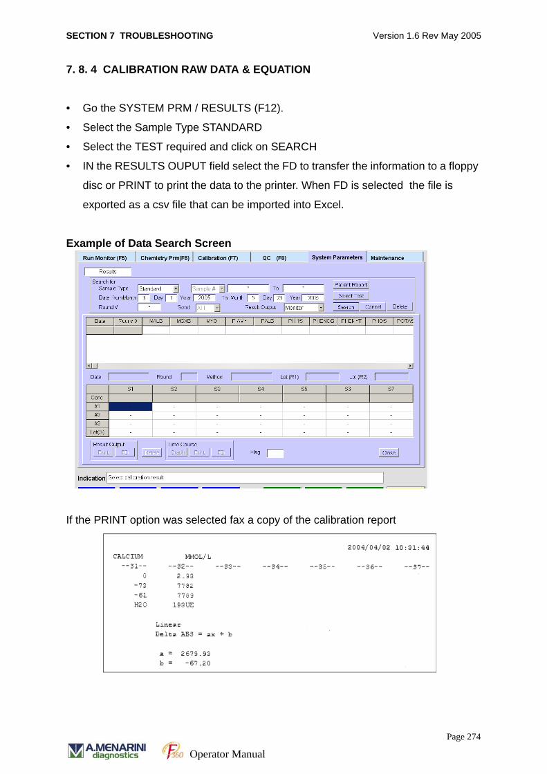
SECTION 7 TROUBLESHOOTING Version 1.6 Rev May 2005
7. 8. 4 CALIBRATION RAW DATA & EQUATION
• Go the SYSTEM PRM / RESULTS (F12).
• Select the Sample Type STANDARD
• Select the TEST required and click on SEARCH
• IN the RESULTS OUPUT field select the FD to transfer the information to a floppy
disc or PRINT to print the data to the printer. When FD is selected the file is
exported as a csv file that can be imported into Excel.
Example of Data Search Screen
If the PRINT option was selected fax a copy of the calibration report
Page 274
Operator Manual
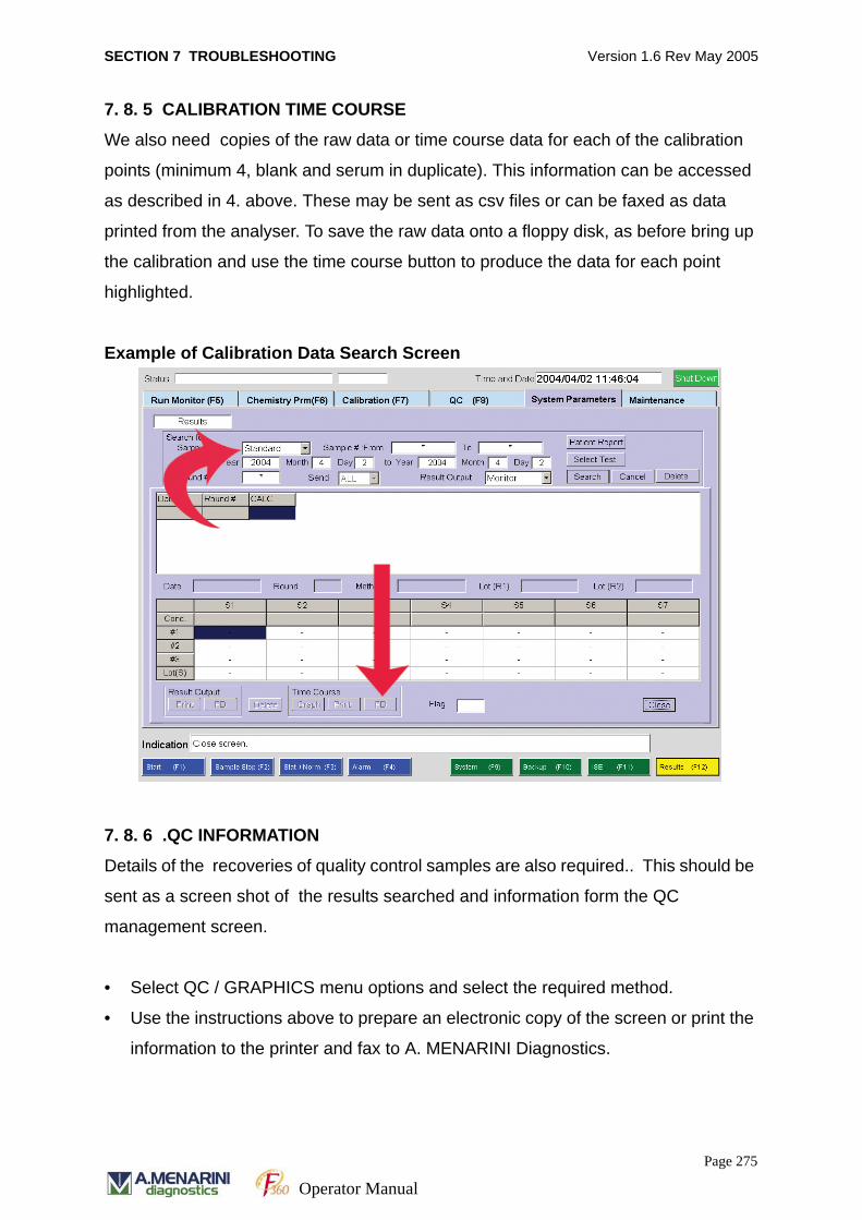
SECTION 7 TROUBLESHOOTING Version 1.6 Rev May 2005
7. 8. 5 CALIBRATION TIME COURSE
We also need copies of the raw data or time course data for each of the calibration
points (minimum 4, blank and serum in duplicate). This information can be accessed
as described in 4. above. These may be sent as csv files or can be faxed as data
printed from the analyser. To save the raw data onto a floppy disk, as before bring up
the calibration and use the time course button to produce the data for each point
highlighted.
Example of Calibration Data Search Screen
7. 8. 6 .QC INFORMATION
Details of the recoveries of quality control samples are also required.. This should be
sent as a screen shot of the results searched and information form the QC
management screen.
• Select QC / GRAPHICS menu options and select the required method.
• Use the instructions above to prepare an electronic copy of the screen or print the
information to the printer and fax to A. MENARINI Diagnostics.
Page 275
Operator Manual
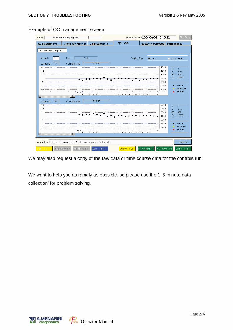
SECTION 7 TROUBLESHOOTING Version 1.6 Rev May 2005
Example of QC management screen
We may also request a copy of the raw data or time course data for the controls run.
We want to help you as rapidly as possible, so please use the 1 '5 minute data
collection' for problem solving.
Page 276
Operator Manual

SECTION 8 ALARM CODES Version 1.6 Rev May 2005
SECTION 8
ALARM CODES
Page 277Operator Manual
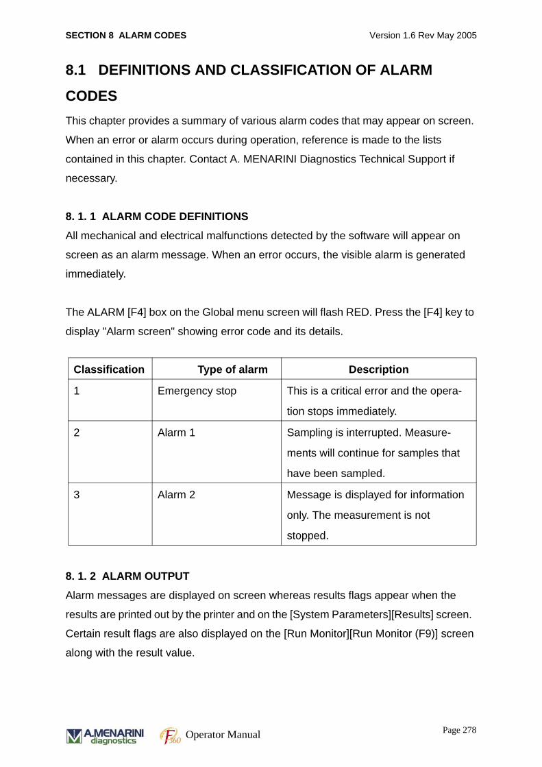
SECTION 8 ALARM CODES Version 1.6 Rev May 2005
8.1 DEFINITIONS AND CLASSIFICATION OF ALARM
CODESThis chapter provides a summary of various alarm codes that may appear on screen.
When an error or alarm occurs during operation, reference is made to the lists
contained in this chapter. Contact A. MENARINI Diagnostics Technical Support if
necessary.
8. 1. 1 ALARM CODE DEFINITIONS
All mechanical and electrical malfunctions detected by the software will appear on
screen as an alarm message. When an error occurs, the visible alarm is generated
immediately.
The ALARM [F4] box on the Global menu screen will flash RED. Press the [F4] key to
display "Alarm screen" showing error code and its details.
8. 1. 2 ALARM OUTPUT
Alarm messages are displayed on screen whereas results flags appear when the
results are printed out by the printer and on the [System Parameters][Results] screen.
Certain result flags are also displayed on the [Run Monitor][Run Monitor (F9)] screen
along with the result value.
Classification Type of alarm Description
1 Emergency stop This is a critical error and the opera-
tion stops immediately.
2 Alarm 1 Sampling is interrupted. Measure-
ments will continue for samples that
have been sampled.
3 Alarm 2 Message is displayed for information
only. The measurement is not
stopped.
Page 278Operator Manual

SECTION 8 ALARM CODES Version 1.6 Rev May 2005
8. 1. 3 ALARM CODE NUMBERS
The alarm code number consists of a combination of unit number and the error
number assigned to each error.
Each alarm code has 4 digits and consists of 2-digit unit number and 2-digit error
number (e.g. 2252, where 22 is the unit number and 52 is the error code number.).
• Unit numbers assigned: 01 – 99
• Error number assigned: 01 – 99
Page 279Operator Manual
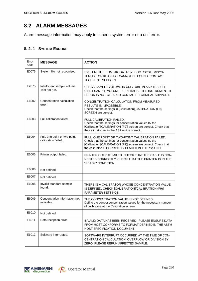
SECTION 8 ALARM CODES Version 1.6 Rev May 2005
8.2 ALARM MESSAGESAlarm message information may apply to either a system error or a unit error.
8. 2. 1 SYSTEM ERRORS
Error code
MESSAGE ACTION
E0075 System file not recognised SYSTEM FILE /HOME/KOGATA/SYSBOOT/SYSTEM/SYS-TEM.TXT OR KHAN.TXT CANNOT BE FOUND. CONTACT TECHNICAL SUPPORT.
E2875 Insufficient sample volume. Test not run.
CHECK SAMPLE VOLUME IN CUP/TUBE IN ASP. IF SUFFI-CIENT SAMPLE VOLUME RE-INITIALISE THE INSTRUMENT. IF ERROR IS NOT CLEARED CONTACT TECHNICAL SUPPORT.
E6002 Concentration calculation error.
CONCENTRATION CALCULATION FROM MEASURED RESULTS IS IMPOSSIBLE.Check that the settings in [Calibration][CALIBRATION (F9)] SCREEN are correct.
E6003 Full calibration failed. FULL CALIBRATION FAILED.Check that the settings for concentration values IN the [Calibration][CALIBRATION (F9)] screen are correct. Check that the calibrator set in the ASP unit is correct.
E6004 Full, one point or two-point calibration failed.
FULL, ONE POINT OR TWO-POINT CALIBRATION FAILED.Check that the settings for concentration values IN the [Calibration][CALIBRATION (F9)] screen are correct. Check that the calibrator IS CORRECTLY PLACED IN THE asp UNIT.
E6005 Printer output failed. PRINTER OUTPUT FAILED. CHECK THAT THE CABLE IS CON-NECTED CORRECTLY. CHECK THAT THE PRINTER IS IN THE "READY" CONDITION.
E6006 Not defined.
E6007 Not defined.
E6008 Invalid standard sample found.
THERE IS A CALIBRATOR WHOSE CONCENTRATION VALUE IS DEFINED. CHECK [CALIBRATION][CALIBRATION (F9)] PARAMETER SETTINGS.
E6009 Concentration information not available.
THE CONCENTRATION VALUE IS NOT DEFINED.Define the correct concentration values for the necessary number of calibrators at the Calibration screen
E6010 Not defined.
E6011 Data reception error. INVALID DATA HAS BEEN RECEIVED. PLEASE ENSURE DATA FROM HOST CONFORMS TO FORMAT DEFINED IN THE ASTM HOST SPECIFICATION DOCUMENT.
E6012 Software interrupted. SOFTWARE INTERRUPT OCCURRED AT THE TIME OF CON-CENTRATION CALCULATION, OVERFLOW OR DIVISION BY ZERO. PLEASE RERUN AFFECTED SAMPLE.
Page 280Operator Manual
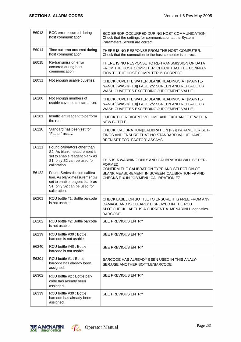
SECTION 8 ALARM CODES Version 1.6 Rev May 2005
E6013 BCC error occurred during host communication.
BCC ERROR OCCURRED DURING HOST COMMUNICATION.Check that the settings for communication at the System Parameters Screen are correct.
E6014 Time out error occurred during host communication.
THERE IS NO RESPONSE FROM THE HOST COMPUTER.Check that the connection to the host computer is correct.
E6015 Re-transmission error occurred during host communication.
THERE IS NO RESPONSE TO RE-TRANSMISSION OF DATA FROM THE HOST COMPUTER. CHECK THAT THE CONNEC-TION TO THE HOST COMPUTER IS CORRECT.
E6051 Not enough usable cuvettes. CHECK CUVETTE WATER BLANK READINGS AT [MAINTE-NANCE][WASH(F10)] PAGE 2/2 SCREEN AND REPLACE OR WASH CUVETTES EXCEEDING JUDGEMENT VALUE.
E6100 Not enough numbers of usable cuvettes to start a run.
CHECK CUVETTE WATER BLANK READINGS AT [MAINTE-NANCE][WASH(F10)] PAGE 2/2 SCREEN AND REPLACE OR WASH CUVETTES EXCEEDING JUDGEMENT VALUE.
E6101 Insufficient reagent to perform the run.
CHECK THE REAGENT VOLUME AND EXCHANGE IT WITH A NEW BOTTLE.
E6120 Standard has been set for “Factor” assay.
CHECK [CALIBRATION][CALIBRATION (F9)] PARAMETER SET-TINGS AND ENSURE THAT NO STANDARD VALUE HAVE BEEN SET FOR ‘FACTOR’ ASSAYS.
E6121 Found calibrators other than S2. As blank measurement is set to enable reagent blank as S1, only S2 can be used for calibration.
THIS IS A WARNING ONLY AND CALIBRATION WILL BE PER-FORMED.CONFIRM THE CALIBRATION TYPE AND SELECTION OF BLANK MEASUREMENT IN SCREEN ‘CALIBRATION F9 AND CHECKS F10 IN JOB MENU CALIBRATION F7
E6122 Found Series dilution calibra-tion. As blank measurement is set to enable reagent blank as S1, only S2 can be used for calibration.
E6201 RCU bottle #1: Bottle barcode is not usable.
CHECK LABEL ON BOTTLE TO ENSURE IT IS FREE FROM ANY DAMAGE AND IS CLEARLY DISPLAYED IN THE RCU SLOT.CHECK LABEL IS A CURRENT A. MENARINI Diagnostics BARCODE.
E6202 RCU bottle #2: Bottle barcode is not usable.
SEE PREVIOUS ENTRY
E6239 RCU bottle #39 : Bottle barcode is not usable.
SEE PREVIOUS ENTRY
E6240 RCU bottle #40 : Bottle barcode is not usable.
SEE PREVIOUS ENTRY
E6301 RCU bottle #1 : Bottle barcode has already been assigned.
BARCODE HAS ALREADY BEEN USED IN THIS ANALY-SER.USE ANOTHER BOTTLE/BARCODE
E6302 RCU bottle #2 : Bottle bar-code has already been assigned.
SEE PREVIOUS ENTRY
E6339 RCU bottle #39 : Bottle barcode has already been assigned.
SEE PREVIOUS ENTRY
Page 281Operator Manual
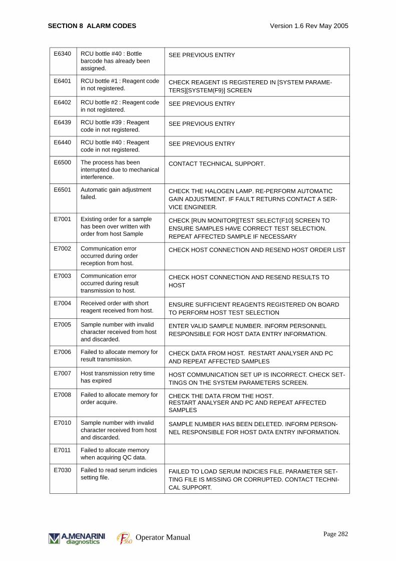
SECTION 8 ALARM CODES Version 1.6 Rev May 2005
E6340 RCU bottle #40 : Bottle barcode has already been assigned.
SEE PREVIOUS ENTRY
E6401 RCU bottle #1 : Reagent code in not registered.
CHECK REAGENT IS REGISTERED IN [SYSTEM PARAME-TERS][SYSTEM(F9)] SCREEN
E6402 RCU bottle #2 : Reagent code in not registered.
SEE PREVIOUS ENTRY
E6439 RCU bottle #39 : Reagent code in not registered.
SEE PREVIOUS ENTRY
E6440 RCU bottle #40 : Reagent code in not registered.
SEE PREVIOUS ENTRY
E6500 The process has been interrupted due to mechanical interference.
CONTACT TECHNICAL SUPPORT.
E6501 Automatic gain adjustment failed.
CHECK THE HALOGEN LAMP. RE-PERFORM AUTOMATIC GAIN ADJUSTMENT. IF FAULT RETURNS CONTACT A SER-VICE ENGINEER.
E7001 Existing order for a sample has been over written with order from host Sample
CHECK [RUN MONITOR][TEST SELECT(F10] SCREEN TO ENSURE SAMPLES HAVE CORRECT TEST SELECTION. REPEAT AFFECTED SAMPLE IF NECESSARY
E7002 Communication error occurred during order reception from host.
CHECK HOST CONNECTION AND RESEND HOST ORDER LIST
E7003 Communication error occurred during result transmission to host.
CHECK HOST CONNECTION AND RESEND RESULTS TO HOST
E7004 Received order with short reagent received from host.
ENSURE SUFFICIENT REAGENTS REGISTERED ON BOARD TO PERFORM HOST TEST SELECTION
E7005 Sample number with invalid character received from host and discarded.
ENTER VALID SAMPLE NUMBER. INFORM PERSONNEL RESPONSIBLE FOR HOST DATA ENTRY INFORMATION.
E7006 Failed to allocate memory for result transmission.
CHECK DATA FROM HOST. RESTART ANALYSER AND PC AND REPEAT AFFECTED SAMPLES
E7007 Host transmission retry time has expired
HOST COMMUNICATION SET UP IS INCORRECT. CHECK SET-TINGS ON THE SYSTEM PARAMETERS SCREEN.
E7008 Failed to allocate memory for order acquire.
CHECK THE DATA FROM THE HOST.RESTART ANALYSER AND PC AND REPEAT AFFECTED SAMPLES
E7010 Sample number with invalid character received from host and discarded.
SAMPLE NUMBER HAS BEEN DELETED. INFORM PERSON-NEL RESPONSIBLE FOR HOST DATA ENTRY INFORMATION.
E7011 Failed to allocate memory when acquiring QC data.
E7030 Failed to read serum indicies setting file.
FAILED TO LOAD SERUM INDICIES FILE. PARAMETER SET-TING FILE IS MISSING OR CORRUPTED. CONTACT TECHNI-CAL SUPPORT.
Page 282Operator Manual
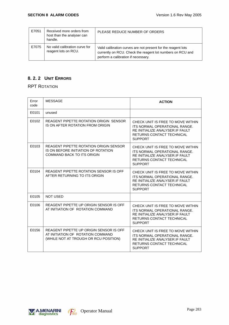
SECTION 8 ALARM CODES Version 1.6 Rev May 2005
8. 2. 2 UNIT ERRORS
RPT ROTATION
E7051 Received more orders from host than the analyser can handle.
PLEASE REDUCE NUMBER OF ORDERS
E7075 No valid calibration curve for reagent lots on RCU.
Valid calibration curves are not present for the reagent lots currently on RCU. Check the reagent lot numbers on RCU and perform a calibration if necessary.
Error code
MESSAGE ACTION
E0101 unused
E0102 REAGENT PIPETTE ROTATION ORIGIN SENSOR IS ON AFTER ROTATION FROM ORIGIN
CHECK UNIT IS FREE TO MOVE WITHIN ITS NORMAL OPERATIONAL RANGE.RE INITIALIZE ANALYSER.IF FAULT RETURNS CONTACT TECHNICAL SUPPORT
E0103 REAGENT PIPETTE ROTATION ORIGIN SENSOR IS ON BEFORE INITIATION OF ROTATION COMMAND BACK TO ITS ORIGIN
CHECK UNIT IS FREE TO MOVE WITHIN ITS NORMAL OPERATIONAL RANGE.RE INITIALIZE ANALYSER.IF FAULT RETURNS CONTACT TECHNICAL SUPPORT
E0104 REAGENT PIPETTE ROTATION SENSOR IS OFF AFTER RETURNING TO ITS ORIGIN
CHECK UNIT IS FREE TO MOVE WITHIN ITS NORMAL OPERATIONAL RANGE.RE INITIALIZE ANALYSER.IF FAULT RETURNS CONTACT TECHNICAL SUPPORT
E0105 NOT USED
E0106 REAGENT PIPETTE UP ORIGIN SENSOR IS OFF AT INITIATION OF ROTATION COMMAND
CHECK UNIT IS FREE TO MOVE WITHIN ITS NORMAL OPERATIONAL RANGE.RE INITIALIZE ANALYSER.IF FAULT RETURNS CONTACT TECHNICAL SUPPORT
E0156 REAGENT PIPETTE UP ORIGIN SENSOR IS OFF AT INITIATION OF ROTATION COMMAND(WHILE NOT AT TROUGH OR RCU POSITION)
CHECK UNIT IS FREE TO MOVE WITHIN ITS NORMAL OPERATIONAL RANGE.RE INITIALIZE ANALYSER.IF FAULT RETURNS CONTACT TECHNICAL SUPPORT
Page 283Operator Manual
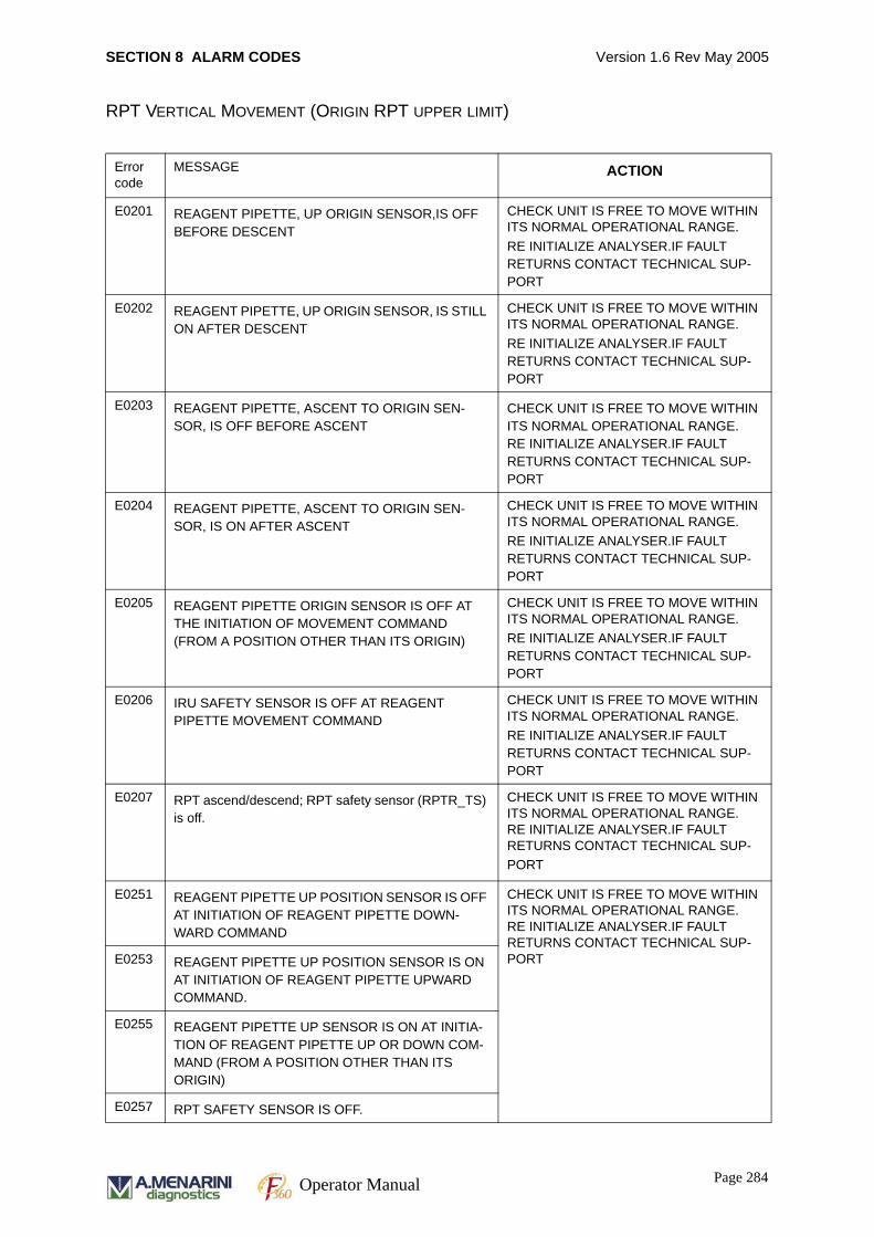
SECTION 8 ALARM CODES Version 1.6 Rev May 2005
RPT VERTICAL MOVEMENT (ORIGIN RPT UPPER LIMIT)
Error code
MESSAGE ACTION
E0201 REAGENT PIPETTE, UP ORIGIN SENSOR,IS OFF BEFORE DESCENT
CHECK UNIT IS FREE TO MOVE WITHIN ITS NORMAL OPERATIONAL RANGE.RE INITIALIZE ANALYSER.IF FAULT RETURNS CONTACT TECHNICAL SUP-PORT
E0202 REAGENT PIPETTE, UP ORIGIN SENSOR, IS STILL ON AFTER DESCENT
CHECK UNIT IS FREE TO MOVE WITHIN ITS NORMAL OPERATIONAL RANGE.RE INITIALIZE ANALYSER.IF FAULT RETURNS CONTACT TECHNICAL SUP-PORT
E0203 REAGENT PIPETTE, ASCENT TO ORIGIN SEN-SOR, IS OFF BEFORE ASCENT
CHECK UNIT IS FREE TO MOVE WITHIN ITS NORMAL OPERATIONAL RANGE. RE INITIALIZE ANALYSER.IF FAULT RETURNS CONTACT TECHNICAL SUP-PORT
E0204 REAGENT PIPETTE, ASCENT TO ORIGIN SEN-SOR, IS ON AFTER ASCENT
CHECK UNIT IS FREE TO MOVE WITHIN ITS NORMAL OPERATIONAL RANGE.RE INITIALIZE ANALYSER.IF FAULT RETURNS CONTACT TECHNICAL SUP-PORT
E0205 REAGENT PIPETTE ORIGIN SENSOR IS OFF AT THE INITIATION OF MOVEMENT COMMAND (FROM A POSITION OTHER THAN ITS ORIGIN)
CHECK UNIT IS FREE TO MOVE WITHIN ITS NORMAL OPERATIONAL RANGE.RE INITIALIZE ANALYSER.IF FAULT RETURNS CONTACT TECHNICAL SUP-PORT
E0206 IRU SAFETY SENSOR IS OFF AT REAGENT PIPETTE MOVEMENT COMMAND
CHECK UNIT IS FREE TO MOVE WITHIN ITS NORMAL OPERATIONAL RANGE.RE INITIALIZE ANALYSER.IF FAULT RETURNS CONTACT TECHNICAL SUP-PORT
E0207 RPT ascend/descend; RPT safety sensor (RPTR_TS) is off.
CHECK UNIT IS FREE TO MOVE WITHIN ITS NORMAL OPERATIONAL RANGE.RE INITIALIZE ANALYSER.IF FAULT RETURNS CONTACT TECHNICAL SUP-PORT
E0251 REAGENT PIPETTE UP POSITION SENSOR IS OFF AT INITIATION OF REAGENT PIPETTE DOWN-WARD COMMAND
CHECK UNIT IS FREE TO MOVE WITHIN ITS NORMAL OPERATIONAL RANGE.RE INITIALIZE ANALYSER.IF FAULT RETURNS CONTACT TECHNICAL SUP-PORTE0253 REAGENT PIPETTE UP POSITION SENSOR IS ON
AT INITIATION OF REAGENT PIPETTE UPWARD COMMAND.
E0255 REAGENT PIPETTE UP SENSOR IS ON AT INITIA-TION OF REAGENT PIPETTE UP OR DOWN COM-MAND (FROM A POSITION OTHER THAN ITS ORIGIN)
E0257 RPT SAFETY SENSOR IS OFF.
Page 284Operator Manual
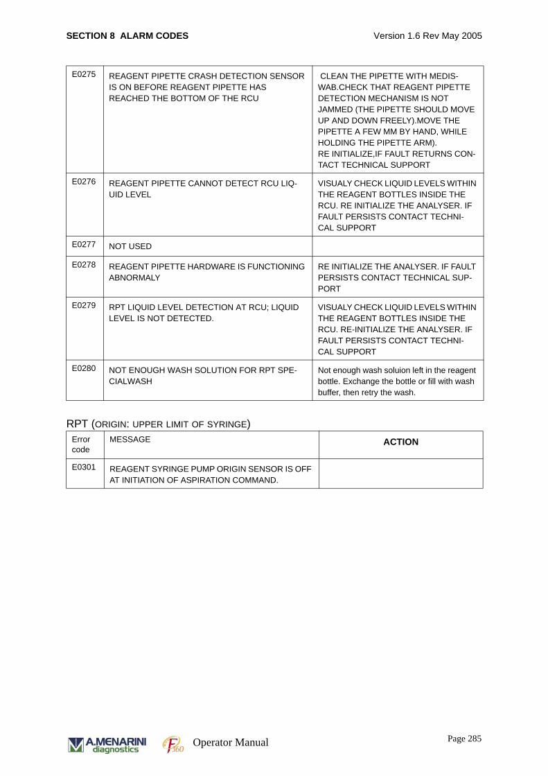
SECTION 8 ALARM CODES Version 1.6 Rev May 2005
RPT (ORIGIN: UPPER LIMIT OF SYRINGE)
E0275 REAGENT PIPETTE CRASH DETECTION SENSOR IS ON BEFORE REAGENT PIPETTE HAS REACHED THE BOTTOM OF THE RCU
CLEAN THE PIPETTE WITH MEDIS-WAB.CHECK THAT REAGENT PIPETTE DETECTION MECHANISM IS NOT JAMMED (THE PIPETTE SHOULD MOVE UP AND DOWN FREELY).MOVE THE PIPETTE A FEW MM BY HAND, WHILE HOLDING THE PIPETTE ARM).RE INITIALIZE,IF FAULT RETURNS CON-TACT TECHNICAL SUPPORT
E0276 REAGENT PIPETTE CANNOT DETECT RCU LIQ-UID LEVEL
VISUALY CHECK LIQUID LEVELS WITHIN THE REAGENT BOTTLES INSIDE THE RCU. RE INITIALIZE THE ANALYSER. IF FAULT PERSISTS CONTACT TECHNI-CAL SUPPORT
E0277 NOT USED
E0278 REAGENT PIPETTE HARDWARE IS FUNCTIONING ABNORMALY
RE INITIALIZE THE ANALYSER. IF FAULT PERSISTS CONTACT TECHNICAL SUP-PORT
E0279 RPT LIQUID LEVEL DETECTION AT RCU; LIQUID LEVEL IS NOT DETECTED.
VISUALY CHECK LIQUID LEVELS WITHIN THE REAGENT BOTTLES INSIDE THE RCU. RE-INITIALIZE THE ANALYSER. IF FAULT PERSISTS CONTACT TECHNI-CAL SUPPORT
E0280 NOT ENOUGH WASH SOLUTION FOR RPT SPE-CIALWASH
Not enough wash soluion left in the reagent bottle. Exchange the bottle or fill with wash buffer, then retry the wash.
Error code
MESSAGE ACTION
E0301 REAGENT SYRINGE PUMP ORIGIN SENSOR IS OFF AT INITIATION OF ASPIRATION COMMAND.
Page 285Operator Manual
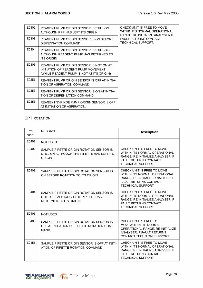
SECTION 8 ALARM CODES Version 1.6 Rev May 2005
SPT ROTATION
E0302 REAGENT PUMP ORIGIN SENSOR IS STILL ON ALTHOUGH RPP HAS LEFT ITS ORIGIN
CHECK UNIT IS FREE TO MOVE WITHIN ITS NORMAL OPERATIONAL RANGE. RE INITIALIZE ANALYSER.IF FAULT RETURNS CONTACT TECHNICAL SUPPORT.
E0303 REAGENT PUMP ORIGIN SENSOR IS ON BEFORE DISPENSATION COMMAND
E0304 REAGENT PUMP ORIGIN SENSOR IS STILL OFF ALTHOUGH REAGENT PUMP HAS RETURNED TO ITS ORIGIN
E0305 REAGENT PUMP ORIGIN SENSOR IS NOT ON AT INITIATION OF REAGENT PUMP MOVEMENT (WHILE REAGENT PUMP IS NOT AT ITS ORIGIN)
E0351 REAGENT PUMP ORIGIN SENSOR IS OFF AT INITIA-TION OF ASPIRATION COMMAND
E0353 REAGENT PUMP ORIGIN SENSOR IS ON AT INITIA-TION OF DISPENSATION COMMAND
E0355 REAGENT SYRINGE PUMP ORIGIN SENSOR IS OFF AT INITIATION OF ASPIRATION.
Error code
MESSAGE Description
E0401 NOT USED
E0402 SAMPLE PIPETTE ORIGIN ROTATION SENSOR IS STILL ON ALTHOUGH THE PIPETTE HAS LEFT ITS ORIGIN
CHECK UNIT IS FREE TO MOVE WITHIN ITS NORMAL OPERATIONAL RANGE. RE INITIALIZE ANALYSER.IF FAULT RETURNS CONTACT TECHNICAL SUPPORT
E0403 SAMPLE PIPETTE ORIGIN ROTATION SENSOR IS ON BEFORE ROTATION TO ITS ORIGIN
CHECK UNIT IS FREE TO MOVE WITHIN ITS NORMAL OPERATIONAL RANGE. RE INITIALIZE ANALYSER.IF FAULT RETURNS CONTACT TECHNICAL SUPPORT
E0404 SAMPLE PIPETTE ORIGIN ROTATION SENSOR IS STILL OFF ALTHOUGH THE PIPETTE HAS RETURNED TO ITS ORIGIN
CHECK UNIT IS FREE TO MOVE WITHIN ITS NORMAL OPERATIONAL RANGE. RE INITIALIZE ANALYSER.IF FAULT RETURNS CONTACT TECHNICAL SUPPORT
E0405 NOT USED
E0406 SAMPLE PIPETTE ORIGIN ROTATION SENSOR IS OFF AT INITIATION OF PIPETTE ROTATION COM-MAND
CHECK UNIT IS FREE TO MOVEWITHIN ITS NORMAL OPERATIONAL RANGE. RE INITIALIZE ANALYSER.IF FAULT RETURNS CONTACT TECHNICAL SUPPORT
E0456 SAMPLE PIPETTE ORIGIN SENSOR IS OFF AT INITI-ATION OF PIPETTE ROTATION COMMAND
CHECK UNIT IS FREE TO MOVE WITHIN ITS NORMAL OPERATIONAL RANGE. RE INITIALIZE ANALYSER.IF FAULT RETURNS CONTACT TECHNICAL SUPPORT
Page 286Operator Manual
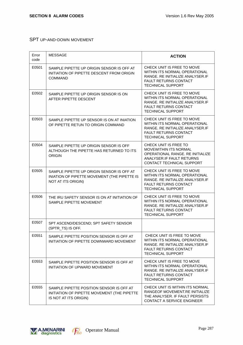
SECTION 8 ALARM CODES Version 1.6 Rev May 2005
SPT UP-AND-DOWN MOVEMENT
Error code
MESSAGE ACTION
E0501 SAMPLE PIPETTE UP ORIGIN SENSOR IS OFF AT INITIATION OF PIPETTE DESCENT FROM ORIGIN COMMAND
CHECK UNIT IS FREE TO MOVE WITHIN ITS NORMAL OPERATIONAL RANGE. RE INITIALIZE ANALYSER.IF FAULT RETURNS CONTACT TECHNICAL SUPPORT
E0502 SAMPLE PIPETTE UP ORIGIN SENSOR IS ON AFTER PIPETTE DESCENT
CHECK UNIT IS FREE TO MOVE WITHIN ITS NORMAL OPERATIONAL RANGE. RE INITIALIZE ANALYSER.IF FAULT RETURNS CONTACT TECHNICAL SUPPORT
E0503 SAMPLE PIPETTE UP SENSOR IS ON AT INIATION OF PIPETTE RETUN TO ORIGIN COMMAND
CHECK UNIT IS FREE TO MOVE WITHIN ITS NORMAL OPERATIONAL RANGE. RE INITIALIZE ANALYSER.IF FAULT RETURNS CONTACT TECHNICAL SUPPORT
E0504 SAMPLE PIPETTE UP ORIGIN SENSOR IS OFF ALTHOUGH THE PIPETTE HAS RETURNED TO ITS ORIGIN
CHECK UNIT IS FREE TO MOVEWITHIN ITS NORMAL OPERATIONAL RANGE. RE INITIALIZE ANALYSER.IF FAULT RETURNS CONTACT TECHNICAL SUPPORT
E0505 SAMPLE PIPETTE UP ORIGIN SENSOR IS OFF AT INIATION OF PIPETTE MOVEMENT (THE PIPETTE IS NOT AT ITS ORIGIN)
CHECK UNIT IS FREE TO MOVE WITHIN ITS NORMAL OPERATIONAL RANGE. RE INITIALIZE ANALYSER.IF FAULT RETURNS CONTACT TECHNICAL SUPPORT
E0506 THE IRU SAFETY SENSOR IS ON AT INITIATION OF SAMPLE PIPETTE MOVEMENT
CHECK UNIT IS FREE TO MOVE WITHIN ITS NORMAL OPERATIONAL RANGE. RE INITIALIZE ANALYSER.IF FAULT RETURNS CONTACT TECHNICAL SUPPORT
E0507 SPT ASCEND/DESCEND; SPT SAFETY SENSOR (SPTR_TS) IS OFF.
E0551 SAMPLE PIPETTE POSITION SENSOR IS OFF AT INITIATION OF PIPETTE DOWNWARD MOVEMENT
CHECK UNIT IS FREE TO MOVE WITHIN ITS NORMAL OPERATIONAL RANGE. RE INITIALIZE ANALYSER.IF FAULT RETURNS CONTACT TECHNICAL SUPPORT
E0553 SAMPLE PIPETTE POSITION SENSOR IS OFF AT INITIATION OF UPWARD MOVEMENT
CHECK UNIT IS FREE TO MOVE WITHIN ITS NORMAL OPERATIONAL RANGE. RE INITIALIZE ANALYSER.IF FAULT RETURNS CONTACT TECHNICAL SUPPORT
E0555 SAMPLE PIPETTE POSITION SENSOR IS OFF AT INITIATION OF PIPETTE MOVEMENT (THE PIPETTE IS NOT AT ITS ORIGIN)
CHECK UNIT IS WITHIN ITS NORMAL RANGEOF MOVEMENT.RE INITIALIZE THE ANALYSER. IF FAULT PERSISTS CONTACT A SERVICE ENGINEER
Page 287Operator Manual
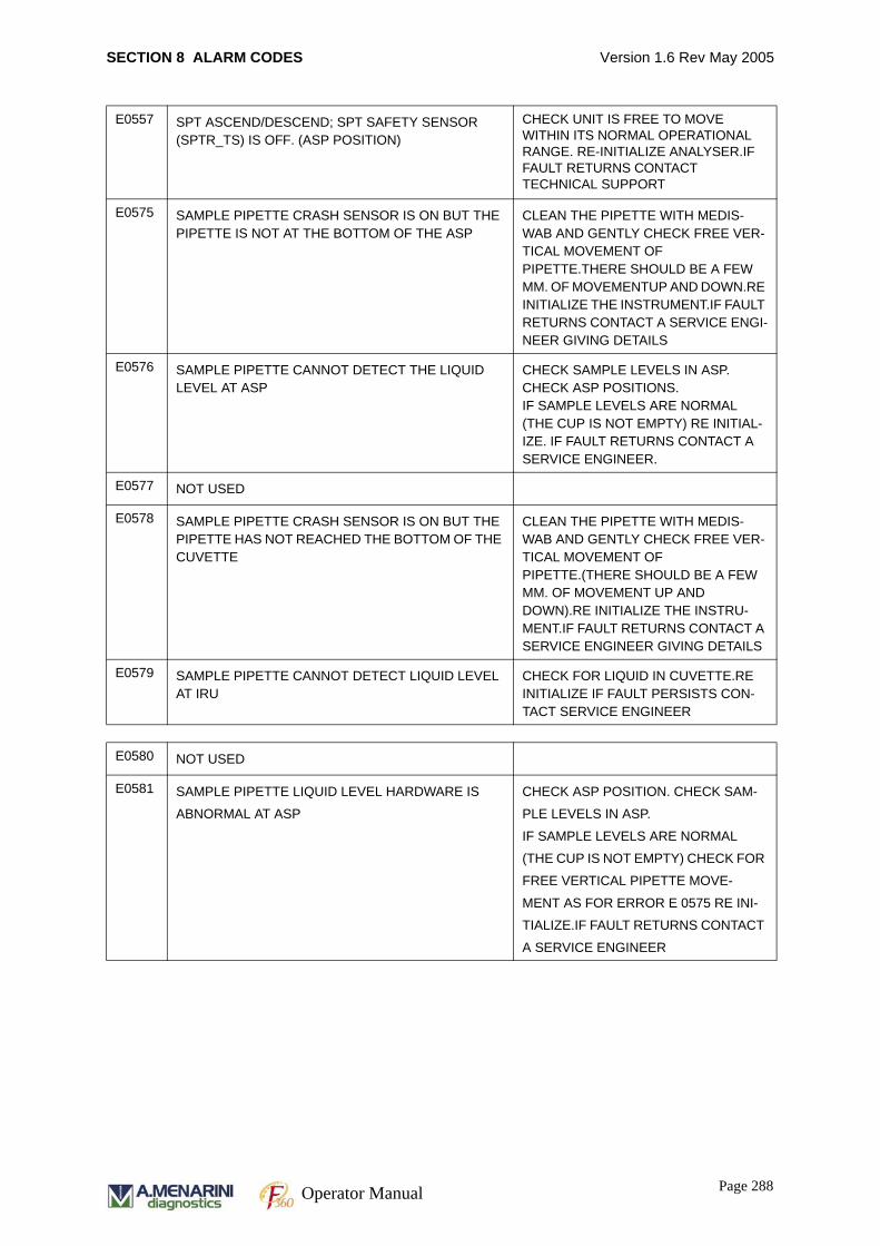
SECTION 8 ALARM CODES Version 1.6 Rev May 2005
E0557 SPT ASCEND/DESCEND; SPT SAFETY SENSOR (SPTR_TS) IS OFF. (ASP POSITION)
CHECK UNIT IS FREE TO MOVE WITHIN ITS NORMAL OPERATIONAL RANGE. RE-INITIALIZE ANALYSER.IF FAULT RETURNS CONTACT TECHNICAL SUPPORT
E0575 SAMPLE PIPETTE CRASH SENSOR IS ON BUT THE PIPETTE IS NOT AT THE BOTTOM OF THE ASP
CLEAN THE PIPETTE WITH MEDIS-WAB AND GENTLY CHECK FREE VER-TICAL MOVEMENT OF PIPETTE.THERE SHOULD BE A FEW MM. OF MOVEMENTUP AND DOWN.RE INITIALIZE THE INSTRUMENT.IF FAULT RETURNS CONTACT A SERVICE ENGI-NEER GIVING DETAILS
E0576 SAMPLE PIPETTE CANNOT DETECT THE LIQUID LEVEL AT ASP
CHECK SAMPLE LEVELS IN ASP. CHECK ASP POSITIONS.IF SAMPLE LEVELS ARE NORMAL (THE CUP IS NOT EMPTY) RE INITIAL-IZE. IF FAULT RETURNS CONTACT A SERVICE ENGINEER.
E0577 NOT USED
E0578 SAMPLE PIPETTE CRASH SENSOR IS ON BUT THE PIPETTE HAS NOT REACHED THE BOTTOM OF THE CUVETTE
CLEAN THE PIPETTE WITH MEDIS-WAB AND GENTLY CHECK FREE VER-TICAL MOVEMENT OF PIPETTE.(THERE SHOULD BE A FEW MM. OF MOVEMENT UP AND DOWN).RE INITIALIZE THE INSTRU-MENT.IF FAULT RETURNS CONTACT A SERVICE ENGINEER GIVING DETAILS
E0579 SAMPLE PIPETTE CANNOT DETECT LIQUID LEVEL AT IRU
CHECK FOR LIQUID IN CUVETTE.RE INITIALIZE IF FAULT PERSISTS CON-TACT SERVICE ENGINEER
E0580 NOT USED
E0581 SAMPLE PIPETTE LIQUID LEVEL HARDWARE IS
ABNORMAL AT ASP
CHECK ASP POSITION. CHECK SAM-
PLE LEVELS IN ASP.
IF SAMPLE LEVELS ARE NORMAL
(THE CUP IS NOT EMPTY) CHECK FOR
FREE VERTICAL PIPETTE MOVE-
MENT AS FOR ERROR E 0575 RE INI-
TIALIZE.IF FAULT RETURNS CONTACT
A SERVICE ENGINEER
Page 288Operator Manual
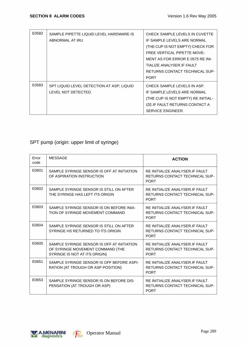
SECTION 8 ALARM CODES Version 1.6 Rev May 2005
SPT pump (origin: upper limit of syringe)
E0582 SAMPLE PIPETTE LIQUID LEVEL HARDWARE IS
ABNORMAL AT IRU
CHECK SAMPLE LEVELS IN CUVETTE
IF SAMPLE LEVELS ARE NORMAL
(THE CUP IS NOT EMPTY) CHECK FOR
FREE VERTICAL PIPETTE MOVE-
MENT AS FOR ERROR E 0575 RE INI-
TIALIZE ANALYSER.IF FAULT
RETURNS CONTACT TECHNICAL SUP-
PORT
E0583 SPT LIQUID LEVEL DETECTION AT ASP; LIQUID
LEVEL NOT DETECTED.
CHECK SAMPLE LEVELS IN ASP.
IF SAMPLE LEVELS ARE NORMAL
(THE CUP IS NOT EMPTY) RE INITIAL-
IZE.IF FAULT RETURNS CONTACT A
SERVICE ENGINEER.
Error code
MESSAGE ACTION
E0601 SAMPLE SYRINGE SENSOR IS OFF AT INITIATION OF ASPIRATION INSTRUCTION
RE INITIALIZE ANALYSER.IF FAULT RETURNS CONTACT TECHNICAL SUP-PORT
E0602 SAMPLE SYRINGE SENSOR IS STILL ON AFTER THE SYRINGE HAS LEFT ITS ORIGIN
RE INITIALIZE ANALYSER.IF FAULT RETURNS CONTACT TECHNICAL SUP-PORT
E0603 SAMPLE SYRINGE SENSOR IS ON BEFORE INIA-TION OF SYRINGE MOVEMENT COMMAND
RE INITIALIZE ANALYSER.IF FAULT RETURNS CONTACT TECHNICAL SUP-PORT
E0604 SAMPLE SYRINGE SENSOR IS STILL ON AFTER SYRINGE HS RETURNED TO ITS ORIGIN
RE INITIALIZE ANALYSER.IF FAULT RETURNS CONTACT TECHNICAL SUP-PORT
E0605 SAMPLE SYRINGE SENSOR IS OFF AT INITIATION OF SYRINGE MOVEMENT COMMAND (THE SYRINGE IS NOT AT ITS ORIGIN)
RE INITIALIZE ANALYSER.IF FAULT RETURNS CONTACT TECHNICAL SUP-PORT
E0651 SAMPLE SYRINGE SENSOR IS OFF BEFORE ASPI-RATION (AT TROUGH OR ASP POSITION)
RE INITIALIZE ANALYSER.IF FAULT RETURNS CONTACT TECHNICAL SUP-PORT
E0653 SAMPLE SYRINGE SENSOR IS ON BEFORE DIS-PENSATION (AT TROUGH OR ASP)
RE INITIALIZE ANALYSER.IF FAULT RETURNS CONTACT TECHNICAL SUP-PORT
Page 289Operator Manual
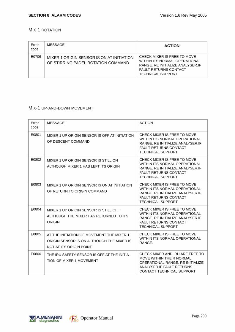
SECTION 8 ALARM CODES Version 1.6 Rev May 2005
MIX-1 ROTATION
MIX-1 UP-AND-DOWN MOVEMENT
Error code
MESSAGE ACTION
E0706 MIXER 1 ORIGIN SENSOR IS ON AT INITIATION OF STIRRING PADEL ROTATION COMMAND
CHECK MIXER IS FREE TO MOVE WITHIN ITS NORMAL OPERATIONAL RANGE. RE INITIALIZE ANALYSER.IF FAULT RETURNS CONTACT TECHNICAL SUPPORT
Error code
MESSAGE ACTION
E0801 MIXER 1 UP ORIGIN SENSOR IS OFF AT INITIATION
OF DESCENT COMMAND
CHECK MIXER IS FREE TO MOVE WITHIN ITS NORMAL OPERATIONAL RANGE. RE INITIALIZE ANALYSER.IF FAULT RETURNS CONTACT TECHNICAL SUPPORT
E0802 MIXER 1 UP ORIGIN SENSOR IS STILL ON
ALTHOUGH MIXER 1 HAS LEFT ITS ORIGIN
CHECK MIXER IS FREE TO MOVE WITHIN ITS NORMAL OPERATIONAL RANGE. RE INITIALIZE ANALYSER.IF FAULT RETURNS CONTACT TECHNICAL SUPPORT
E0803 MIXER 1 UP ORIGIN SENSOR IS ON AT INITIATION
OF RETURN TO ORIGIN COMMAND
CHECK MIXER IS FREE TO MOVE WITHIN ITS NORMAL OPERATIONAL RANGE. RE INITIALIZE ANALYSER.IF FAULT RETURNS CONTACT TECHNICAL SUPPORT
E0804 MIXER 1 UP ORIGIN SENSOR IS STILL OFF
ALTHOUGH THE MIXER HAS RETURNED TO ITS
ORIGIN
CHECK MIXER IS FREE TO MOVE WITHIN ITS NORMAL OPERATIONAL RANGE. RE INITIALIZE ANALYSER.IF FAULT RETURNS CONTACT TECHNICAL SUPPORT
E0805 AT THE INITIATION OF MOVEMENT THE MIXER 1
ORIGIN SENSOR IS ON ALTHOUGH THE MIXER IS
NOT AT ITS ORIGIN POINT
CHECK MIXER IS FREE TO MOVE WITHIN ITS NORMAL OPERATIONAL RANGE.
E0806 THE IRU SAFETY SENSOR IS OFF AT THE INITIA-
TION OF MIXER 1 MOVEMENT
CHECK MIXER AND IRU ARE FREE TO MOVE WITHIN THEIR NORMAL OPERATIONAL RANGE. RE INITIALIZE ANALYSER.IF FAULT RETURNS CONTACT TECHNICAL SUPPORT
Page 290Operator Manual
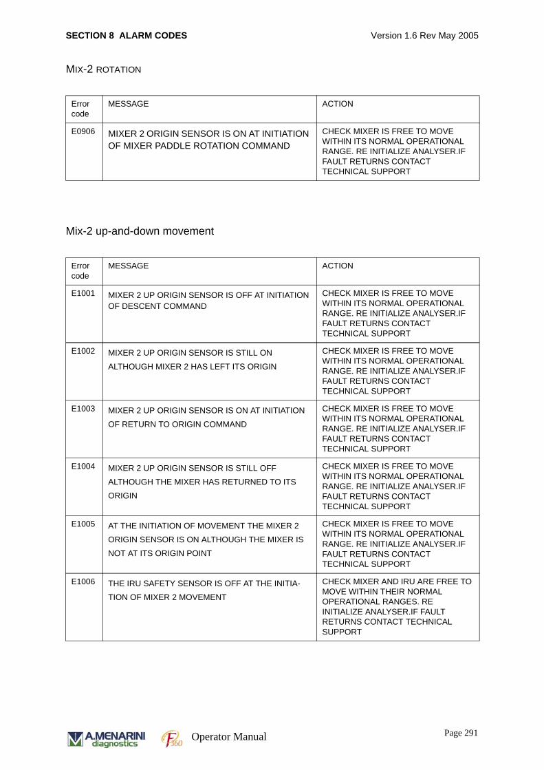
SECTION 8 ALARM CODES Version 1.6 Rev May 2005
MIX-2 ROTATION
Mix-2 up-and-down movement
Error code
MESSAGE ACTION
E0906 MIXER 2 ORIGIN SENSOR IS ON AT INITIATION OF MIXER PADDLE ROTATION COMMAND
CHECK MIXER IS FREE TO MOVE WITHIN ITS NORMAL OPERATIONAL RANGE. RE INITIALIZE ANALYSER.IF FAULT RETURNS CONTACT TECHNICAL SUPPORT
Error code
MESSAGE ACTION
E1001 MIXER 2 UP ORIGIN SENSOR IS OFF AT INITIATION OF DESCENT COMMAND
CHECK MIXER IS FREE TO MOVE WITHIN ITS NORMAL OPERATIONAL RANGE. RE INITIALIZE ANALYSER.IF FAULT RETURNS CONTACT TECHNICAL SUPPORT
E1002 MIXER 2 UP ORIGIN SENSOR IS STILL ON
ALTHOUGH MIXER 2 HAS LEFT ITS ORIGIN
CHECK MIXER IS FREE TO MOVE WITHIN ITS NORMAL OPERATIONAL RANGE. RE INITIALIZE ANALYSER.IF FAULT RETURNS CONTACT TECHNICAL SUPPORT
E1003 MIXER 2 UP ORIGIN SENSOR IS ON AT INITIATION
OF RETURN TO ORIGIN COMMAND
CHECK MIXER IS FREE TO MOVE WITHIN ITS NORMAL OPERATIONAL RANGE. RE INITIALIZE ANALYSER.IF FAULT RETURNS CONTACT TECHNICAL SUPPORT
E1004 MIXER 2 UP ORIGIN SENSOR IS STILL OFF
ALTHOUGH THE MIXER HAS RETURNED TO ITS
ORIGIN
CHECK MIXER IS FREE TO MOVE WITHIN ITS NORMAL OPERATIONAL RANGE. RE INITIALIZE ANALYSER.IF FAULT RETURNS CONTACT TECHNICAL SUPPORT
E1005 AT THE INITIATION OF MOVEMENT THE MIXER 2
ORIGIN SENSOR IS ON ALTHOUGH THE MIXER IS
NOT AT ITS ORIGIN POINT
CHECK MIXER IS FREE TO MOVE WITHIN ITS NORMAL OPERATIONAL RANGE. RE INITIALIZE ANALYSER.IF FAULT RETURNS CONTACT TECHNICAL SUPPORT
E1006 THE IRU SAFETY SENSOR IS OFF AT THE INITIA-
TION OF MIXER 2 MOVEMENT
CHECK MIXER AND IRU ARE FREE TO MOVE WITHIN THEIR NORMAL OPERATIONAL RANGES. RE INITIALIZE ANALYSER.IF FAULT RETURNS CONTACT TECHNICAL SUPPORT
Page 291Operator Manual

SECTION 8 ALARM CODES Version 1.6 Rev May 2005
WU UP-AND-DOWN MOVEMENT
WU PUMP (ORIGIN: UPPER LIMIT OF SYRINGE)
Error code
MESSAGE ACTION
E1101 WASH UNIT ORIGIN SENSOR IS OFF AT INITIATION OF DESCENT COMMAND
CHECK WASH UNIT IS FREE TO MOVE WITHIN ITS NORMAL OPERATIONAL RANGE. RE INITIALIZE ANALYSER.IF FAULT RETURNS CONTACT TECHNICAL SUPPORT
E1102 WASH UNIT ORIGIN SENSOR IS STILL ON ALTHOUGH THE WASH UNIT HAS LEFT ITS ORIGIN
CHECK WASH UNIT IS FREE TO MOVE WITHIN ITS NORMAL OPERATIONAL RANGE. RE INITIALIZE ANALYSER.IF FAULT RETURNS CONTACT TECHNICAL SUPPORT
E1103 WASH UNIT ORIGIN SENSOR IS ON AT INITIATION OF WASH UNIT RETURN TO ORIGIN COMMAND
CHECK WASH UNIT IS FREE TO MOVE WITHIN ITS NORMAL OPERATIONAL RANGE. RE INITIALIZE ANALYSER.IF FAULT RETURNS CONTACT TECHNICAL SUPPORT
E1104 WASH UNIT ORIGIN SENSOR IS STILL OFF ALTHOUGH THE WASH UNIT HAS RETURNED TO ITS ORIGIN
CHECK WASH UNIT IS FREE TO MOVE WITHIN ITS NORMAL OPERATIONAL RANGE. RE INITIALIZE ANALYSER.IF FAULT RETURNS CONTACT TECHNICAL SUPPORTE1105 WU ASCEND/DESCEND AT OFF-ORIGIN; WU ORI-
GIN SENSOR (WU_ZERO) SHOULD BE OFF BEFORE ACTION BUT IS NOT.
E1106 THE IRU SAFETY SENSOR IS OFF AT INITIATION OF WASH UNIT MOVEMENT
CHECK WASH UNIT AND IRU ARE FREE TO MOVE WITHIN THEIR NORMAL OPERATIONAL RANGES.RE INITIALIZE ANALYSER.IF FAULT RETURNS CONTACT TECHNICAL SUP-PORT
Error code
MESSAGE ACTION
E1201 WPP ASPIRATION; WPP ORIGIN SENSOR (WPP_ZERO) IS OFF BEFORE ASPIRATION.
RETRY THE ASPIRATION AND CON-TACT TECHNICAL SUPPORT IF PROB-LEM PERSISTS.
E1202 WASH PUMP SYRINGE ORIGIN SENSOR IS STILL ON ALTHOUGH THE WASH PUMP HAS LEFT ITS ORIGIN
RE INITIALIZE ANALYSER.IF FAULT RETURNS CONTACT TECHNICAL SUP-PORT
E1203 WASH PUMP SYRINGE ORIGIN SENSOR IS ON BEFORE INITIATION OF WASH PUMP MOVEMENT COMMAND (FROM FULLY DISPENSED POSITION)
RE INITIALIZE ANALYSER.IF FAULT RETURNS CONTACT TECHNICAL SUP-PORT
Page 292Operator Manual
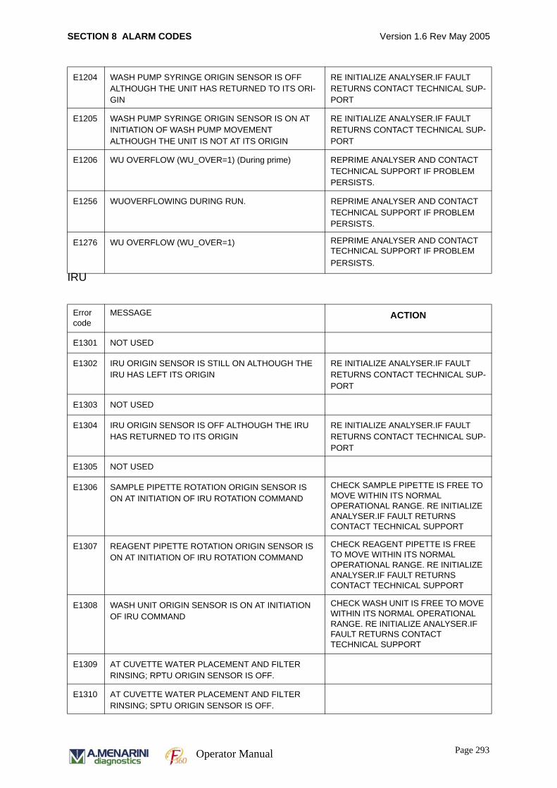
SECTION 8 ALARM CODES Version 1.6 Rev May 2005
IRU
E1204 WASH PUMP SYRINGE ORIGIN SENSOR IS OFF ALTHOUGH THE UNIT HAS RETURNED TO ITS ORI-GIN
RE INITIALIZE ANALYSER.IF FAULT RETURNS CONTACT TECHNICAL SUP-PORT
E1205 WASH PUMP SYRINGE ORIGIN SENSOR IS ON AT INITIATION OF WASH PUMP MOVEMENT ALTHOUGH THE UNIT IS NOT AT ITS ORIGIN
RE INITIALIZE ANALYSER.IF FAULT RETURNS CONTACT TECHNICAL SUP-PORT
E1206 WU OVERFLOW (WU_OVER=1) (During prime) REPRIME ANALYSER AND CONTACT TECHNICAL SUPPORT IF PROBLEM PERSISTS.
E1256 WUOVERFLOWING DURING RUN. REPRIME ANALYSER AND CONTACT TECHNICAL SUPPORT IF PROBLEM PERSISTS.
E1276 WU OVERFLOW (WU_OVER=1) REPRIME ANALYSER AND CONTACT TECHNICAL SUPPORT IF PROBLEM PERSISTS.
Error code
MESSAGE ACTION
E1301 NOT USED
E1302 IRU ORIGIN SENSOR IS STILL ON ALTHOUGH THE IRU HAS LEFT ITS ORIGIN
RE INITIALIZE ANALYSER.IF FAULT RETURNS CONTACT TECHNICAL SUP-PORT
E1303 NOT USED
E1304 IRU ORIGIN SENSOR IS OFF ALTHOUGH THE IRU HAS RETURNED TO ITS ORIGIN
RE INITIALIZE ANALYSER.IF FAULT RETURNS CONTACT TECHNICAL SUP-PORT
E1305 NOT USED
E1306 SAMPLE PIPETTE ROTATION ORIGIN SENSOR IS ON AT INITIATION OF IRU ROTATION COMMAND
CHECK SAMPLE PIPETTE IS FREE TO MOVE WITHIN ITS NORMAL OPERATIONAL RANGE. RE INITIALIZE ANALYSER.IF FAULT RETURNS CONTACT TECHNICAL SUPPORT
E1307 REAGENT PIPETTE ROTATION ORIGIN SENSOR IS ON AT INITIATION OF IRU ROTATION COMMAND
CHECK REAGENT PIPETTE IS FREE TO MOVE WITHIN ITS NORMAL OPERATIONAL RANGE. RE INITIALIZE ANALYSER.IF FAULT RETURNS CONTACT TECHNICAL SUPPORT
E1308 WASH UNIT ORIGIN SENSOR IS ON AT INITIATION OF IRU COMMAND
CHECK WASH UNIT IS FREE TO MOVE WITHIN ITS NORMAL OPERATIONAL RANGE. RE INITIALIZE ANALYSER.IF FAULT RETURNS CONTACT TECHNICAL SUPPORT
E1309 AT CUVETTE WATER PLACEMENT AND FILTER RINSING; RPTU ORIGIN SENSOR IS OFF.
E1310 AT CUVETTE WATER PLACEMENT AND FILTER RINSING; SPTU ORIGIN SENSOR IS OFF.
Page 293Operator Manual
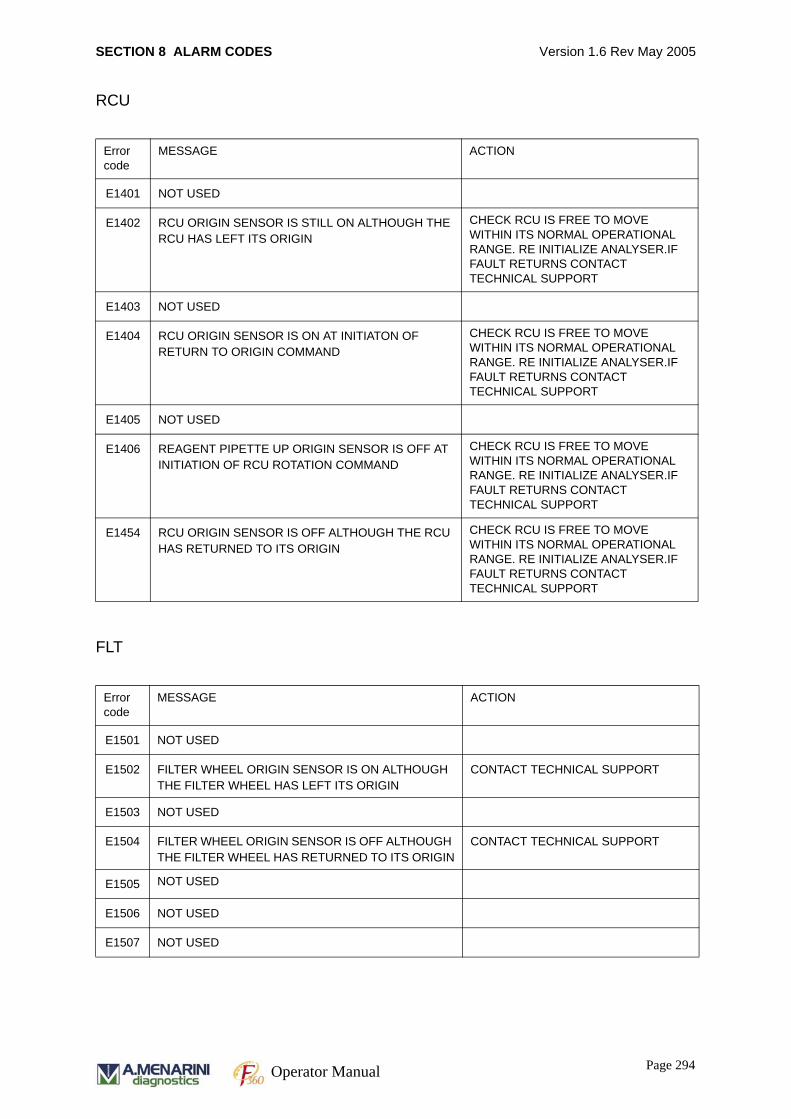
SECTION 8 ALARM CODES Version 1.6 Rev May 2005
RCU
FLT
Error code
MESSAGE ACTION
E1401 NOT USED
E1402 RCU ORIGIN SENSOR IS STILL ON ALTHOUGH THE RCU HAS LEFT ITS ORIGIN
CHECK RCU IS FREE TO MOVE WITHIN ITS NORMAL OPERATIONAL RANGE. RE INITIALIZE ANALYSER.IF FAULT RETURNS CONTACT TECHNICAL SUPPORT
E1403 NOT USED
E1404 RCU ORIGIN SENSOR IS ON AT INITIATON OF RETURN TO ORIGIN COMMAND
CHECK RCU IS FREE TO MOVE WITHIN ITS NORMAL OPERATIONAL RANGE. RE INITIALIZE ANALYSER.IF FAULT RETURNS CONTACT TECHNICAL SUPPORT
E1405 NOT USED
E1406 REAGENT PIPETTE UP ORIGIN SENSOR IS OFF AT INITIATION OF RCU ROTATION COMMAND
CHECK RCU IS FREE TO MOVE WITHIN ITS NORMAL OPERATIONAL RANGE. RE INITIALIZE ANALYSER.IF FAULT RETURNS CONTACT TECHNICAL SUPPORT
E1454 RCU ORIGIN SENSOR IS OFF ALTHOUGH THE RCU HAS RETURNED TO ITS ORIGIN
CHECK RCU IS FREE TO MOVE WITHIN ITS NORMAL OPERATIONAL RANGE. RE INITIALIZE ANALYSER.IF FAULT RETURNS CONTACT TECHNICAL SUPPORT
Error code
MESSAGE ACTION
E1501 NOT USED
E1502 FILTER WHEEL ORIGIN SENSOR IS ON ALTHOUGH THE FILTER WHEEL HAS LEFT ITS ORIGIN
CONTACT TECHNICAL SUPPORT
E1503 NOT USED
E1504 FILTER WHEEL ORIGIN SENSOR IS OFF ALTHOUGH THE FILTER WHEEL HAS RETURNED TO ITS ORIGIN
CONTACT TECHNICAL SUPPORT
E1505 NOT USED
E1506 NOT USED
E1507 NOT USED
Page 294Operator Manual
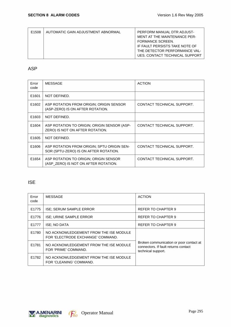
SECTION 8 ALARM CODES Version 1.6 Rev May 2005
ASP
ISE
E1508 AUTOMATIC GAIN ADJUSTMENT ABNORMAL PERFORM MANUAL DTR ADJUST-MENT AT THE MAINTENANCE PER-FORMANCE SCREEN.IF FAULT PERSISTS TAKE NOTE OF THE DETECTOR PERFORMANCE VAL-UES. CONTACT TECHNICAL SUPPORT
Error code
MESSAGE ACTION
E1601 NOT DEFINED.
E1602 ASP ROTATION FROM ORIGIN; ORIGIN SENSOR (ASP-ZERO) IS ON AFTER ROTATION.
CONTACT TECHNICAL SUPPORT.
E1603 NOT DEFINED.
E1604 ASP ROTATION TO ORIGIN; ORIGIN SENSOR (ASP-ZERO) IS NOT ON AFTER ROTATION.
CONTACT TECHNICAL SUPPORT.
E1605 NOT DEFINED.
E1606 ASP ROTATION FROM ORIGIN; SPTU ORIGIN SEN-SOR (SPTU-ZERO) IS ON AFTER ROTATION.
CONTACT TECHNICAL SUPPORT.
E1654 ASP ROTATION TO ORIGIN; ORIGIN SENSOR (ASP_ZERO) IS NOT ON AFTER ROTATION.
CONTACT TECHNICAL SUPPORT.
Error code
MESSAGE ACTION
E1775 ISE; SERUM SAMPLE ERROR REFER TO CHAPTER 9
E1776 ISE; URINE SAMPLE ERROR REFER TO CHAPTER 9
E1777 ISE; NO DATA REFER TO CHAPTER 9
E1780 NO ACKNOWLEDGEMENT FROM THE ISE MODULE FOR ‘ELECTRODE EXCHANGE’ COMMAND.
Broken communication or poor contact at connectors. If fault returns contact technical support.
E1781 NO ACKNOWLEDGEMENT FROM THE ISE MODULE FOR ‘PRIME’ COMMAND.
E1782 NO ACKNOWLEDGEMENT FROM THE ISE MODULE FOR ‘CLEANING’ COMMAND.
Page 295Operator Manual
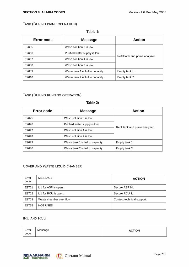
SECTION 8 ALARM CODES Version 1.6 Rev May 2005
TANK (DURING PRIME OPERATION)
TANK (DURING RUNNING OPERATION)
COVER AND WASTE LIQUID CHAMBER
IRU AND RCU
Table 1:
Error code Message Action
E2605 Wash solution 3 is low.
Refill tank and prime analyzer.E2606 Purified water supply is low.
E2607 Wash solution 1 is low.
E2608 Wash solution 2 is low.
E2609 Waste tank 1 is full to capacity. Empty tank 1.
E2610 Waste tank 2 is full to capacity. Empty tank 2.
Table 2:
Error code Message Action
E2675 Wash solution 3 is low.
Refill tank and prime analyzer.E2676 Purified water supply is low.
E2677 Wash solution 1 is low.
E2678 Wash solution 2 is low.
E2679 Waste tank 1 is full to capacity. Empty tank 1.
E2680 Waste tank 2 is full to capacity. Empty tank 2.
Error code
MESSAGE ACTION
E2701 Lid for ASP is open. Secure ASP lid.
E2702 Lid for RCU is open. Secure RCU lid.
E2703 Waste chamber over flow Contact technical support.
E2775 NOT USED
Error code
Message ACTION
Page 296Operator Manual
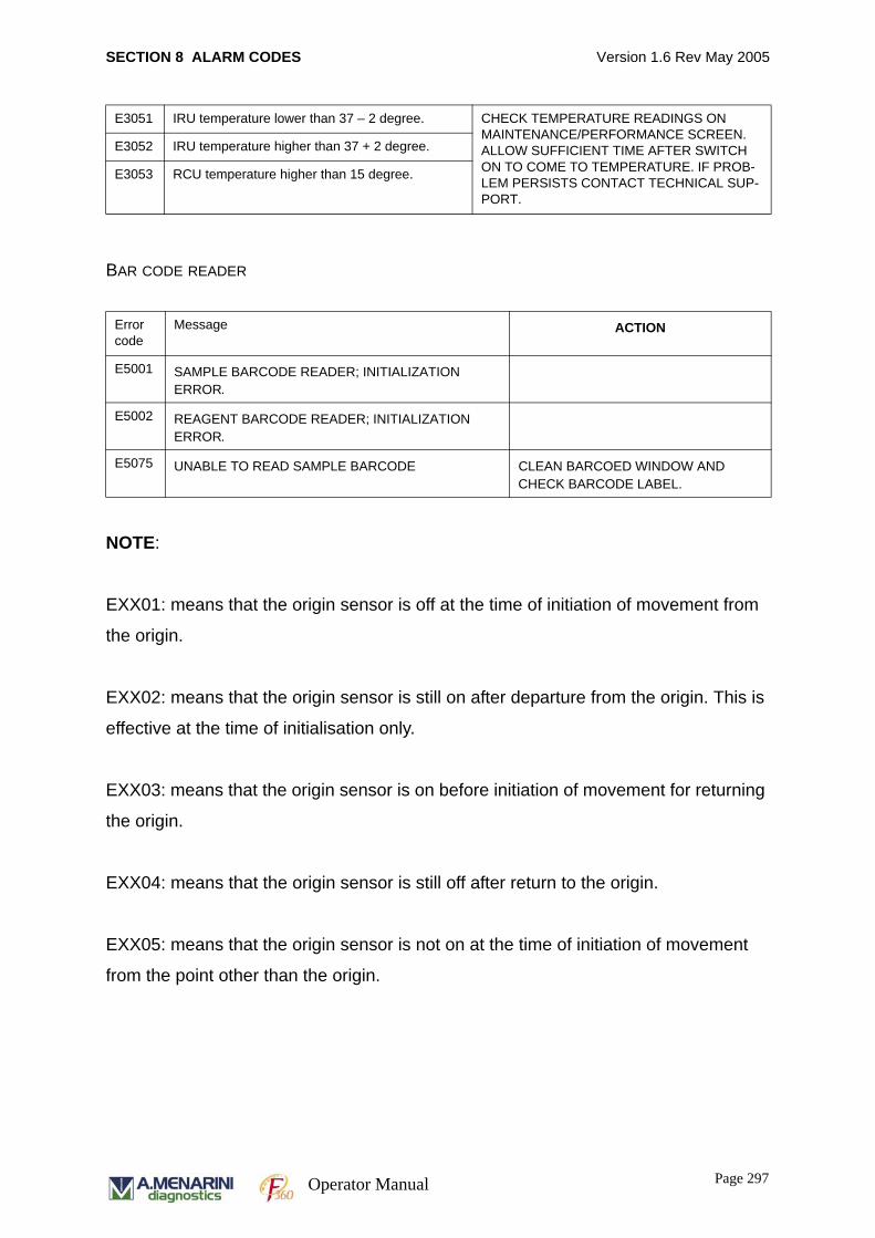
SECTION 8 ALARM CODES Version 1.6 Rev May 2005
BAR CODE READER
NOTE:
EXX01: means that the origin sensor is off at the time of initiation of movement from
the origin.
EXX02: means that the origin sensor is still on after departure from the origin. This is
effective at the time of initialisation only.
EXX03: means that the origin sensor is on before initiation of movement for returning
the origin.
EXX04: means that the origin sensor is still off after return to the origin.
EXX05: means that the origin sensor is not on at the time of initiation of movement
from the point other than the origin.
E3051 IRU temperature lower than 37 – 2 degree. CHECK TEMPERATURE READINGS ON MAINTENANCE/PERFORMANCE SCREEN. ALLOW SUFFICIENT TIME AFTER SWITCH ON TO COME TO TEMPERATURE. IF PROB-LEM PERSISTS CONTACT TECHNICAL SUP-PORT.
E3052 IRU temperature higher than 37 + 2 degree.
E3053 RCU temperature higher than 15 degree.
Error code
Message ACTION
E5001 SAMPLE BARCODE READER; INITIALIZATION ERROR.
E5002 REAGENT BARCODE READER; INITIALIZATION ERROR.
E5075 UNABLE TO READ SAMPLE BARCODE CLEAN BARCOED WINDOW AND CHECK BARCODE LABEL.
Page 297Operator Manual

SECTION 8 ALARM CODES Version 1.6 Rev May 2005
Page 298Operator Manual

SECTION 9 ISE USE AND MAINTENANCE Version 1.6 Rev May 2005
SECTION 9
ISE USE AND MAINTENANCE
Page 299Operator Manual
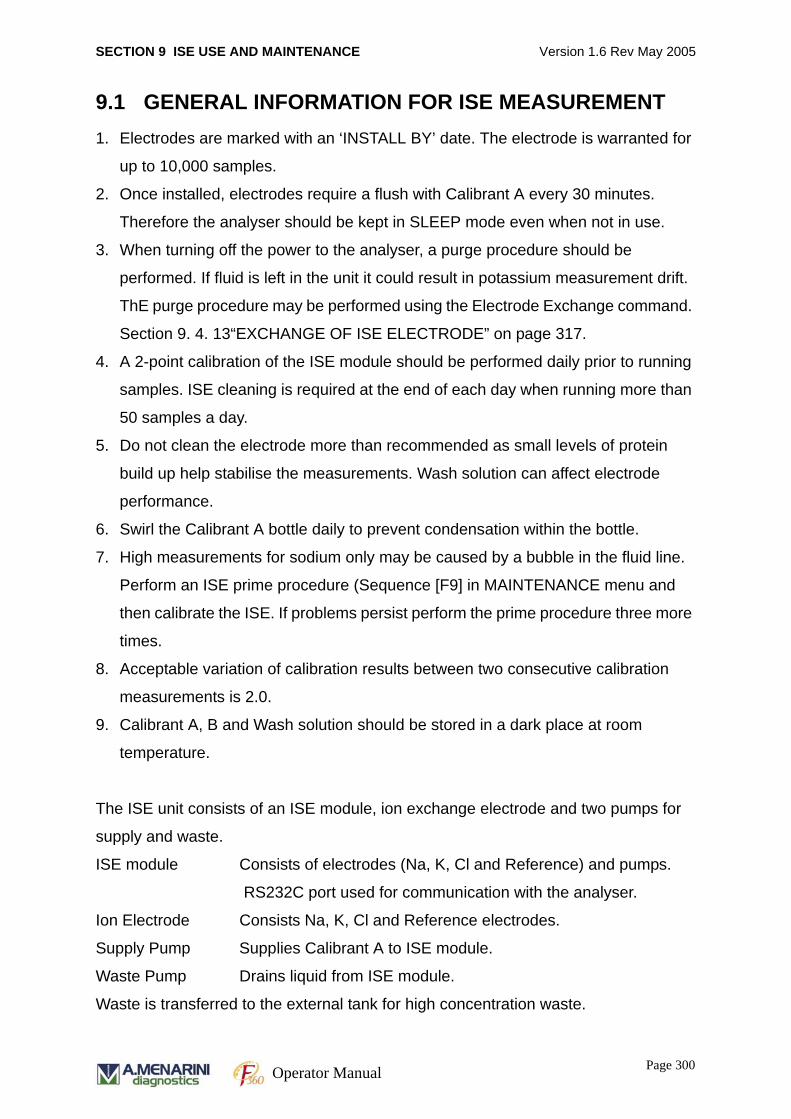
SECTION 9 ISE USE AND MAINTENANCE Version 1.6 Rev May 2005
9.1 GENERAL INFORMATION FOR ISE MEASUREMENT1. Electrodes are marked with an ‘INSTALL BY’ date. The electrode is warranted for
up to 10,000 samples.
2. Once installed, electrodes require a flush with Calibrant A every 30 minutes.
Therefore the analyser should be kept in SLEEP mode even when not in use.
3. When turning off the power to the analyser, a purge procedure should be
performed. If fluid is left in the unit it could result in potassium measurement drift.
ThE purge procedure may be performed using the Electrode Exchange command.
Section 9. 4. 13“EXCHANGE OF ISE ELECTRODE” on page 317.
4. A 2-point calibration of the ISE module should be performed daily prior to running
samples. ISE cleaning is required at the end of each day when running more than
50 samples a day.
5. Do not clean the electrode more than recommended as small levels of protein
build up help stabilise the measurements. Wash solution can affect electrode
performance.
6. Swirl the Calibrant A bottle daily to prevent condensation within the bottle.
7. High measurements for sodium only may be caused by a bubble in the fluid line.
Perform an ISE prime procedure (Sequence [F9] in MAINTENANCE menu and
then calibrate the ISE. If problems persist perform the prime procedure three more
times.
8. Acceptable variation of calibration results between two consecutive calibration
measurements is 2.0.
9. Calibrant A, B and Wash solution should be stored in a dark place at room
temperature.
The ISE unit consists of an ISE module, ion exchange electrode and two pumps for
supply and waste.
ISE module Consists of electrodes (Na, K, Cl and Reference) and pumps.
RS232C port used for communication with the analyser.
Ion Electrode Consists Na, K, Cl and Reference electrodes.
Supply Pump Supplies Calibrant A to ISE module.
Waste Pump Drains liquid from ISE module.
Waste is transferred to the external tank for high concentration waste.
Page 300Operator Manual

SECTION 9 ISE USE AND MAINTENANCE Version 1.6 Rev May 2005
9.2 ISE THEORYElectrolyte measurements in blood samples were traditionally performed using flame
photometry, in which a sample, diluted with a known concentration of a reference ion
(usually lithium or caesium), is aerosolised and passes through a flame which excites
the cations. They re-emit the energy as light of different frequencies, the amplitude of
emission is proportional to the ion concentration in the sample. The development of
selective organic compounds for sodium, potassium, chloride and other electrolytes
has permitted the development of sensors capable of directly measuring biological
fluids throughout the physiological range. These sensors are known as Ion Selective
Electrodes or ISEs.
The F360 electrolyte measurement system measures sodium, potassium and
chloride in biological fluids, using ion selective electrode technology. A diagram of the
electrode measurement system is shown below.
ELECTRODE MEASUREMENT DIAGRAM
Page 301Operator Manual
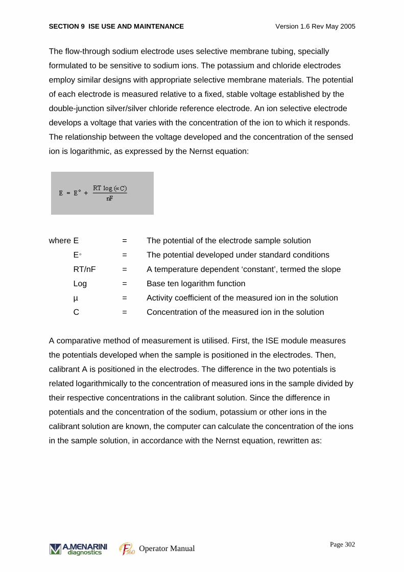
SECTION 9 ISE USE AND MAINTENANCE Version 1.6 Rev May 2005
The flow-through sodium electrode uses selective membrane tubing, specially
formulated to be sensitive to sodium ions. The potassium and chloride electrodes
employ similar designs with appropriate selective membrane materials. The potential
of each electrode is measured relative to a fixed, stable voltage established by the
double-junction silver/silver chloride reference electrode. An ion selective electrode
develops a voltage that varies with the concentration of the ion to which it responds.
The relationship between the voltage developed and the concentration of the sensed
ion is logarithmic, as expressed by the Nernst equation:
where E = The potential of the electrode sample solution
E = The potential developed under standard conditions
RT/nF = A temperature dependent ‘constant’, termed the slope
Log = Base ten logarithm function
µ = Activity coefficient of the measured ion in the solution
C = Concentration of the measured ion in the solution
A comparative method of measurement is utilised. First, the ISE module measures
the potentials developed when the sample is positioned in the electrodes. Then,
calibrant A is positioned in the electrodes. The difference in the two potentials is
related logarithmically to the concentration of measured ions in the sample divided by
their respective concentrations in the calibrant solution. Since the difference in
potentials and the concentration of the sodium, potassium or other ions in the
calibrant solution are known, the computer can calculate the concentration of the ions
in the sample solution, in accordance with the Nernst equation, rewritten as:
°
Page 302Operator Manual

SECTION 9 ISE USE AND MAINTENANCE Version 1.6 Rev May 2005
where E = ISE potential developed in sample solution
E = ISE potential developed in Calibrant A solution
S = Electrode slope calculated during calibration with Cal A
and B.
Cx = Concentration of ion in the sample
Cs = Concentration of ion in the Calibrant solution
‘S’, the slope, is determined during the calibration using Calibrants A and B, which
have known levels of sodium, potassium and chloride.
E - E° = S log ( Cx / Cs) or Cx = Cs x 10 [(E - E°) / S]
°
Page 303Operator Manual
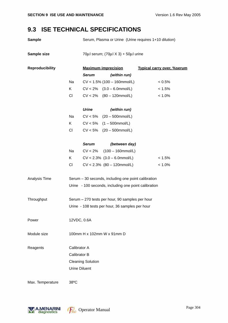
SECTION 9 ISE USE AND MAINTENANCE Version 1.6 Rev May 2005
9.3 ISE TECHNICAL SPECIFICATIONSSample Serum, Plasma or Urine (Urine requires 1+10 dilution)
Sample size 70μl serum; (70μl X 3) + 50μl urine
Reproducibility Maximum imprecision Typical carry over, %serum
Serum (within run)
Na CV < 1.5% (100 – 160mmol/L) < 0.5%
K CV < 2% (3.0 – 6.0mmol/L) < 1.5%
Cl CV < 2% (80 – 120mmol/L) < 1.0%
Urine (within run)
Na CV < 5% (20 – 500mmol/L)
K CV < 5% (1 – 500mmol/L)
Cl CV < 5% (20 – 500mmol/L)
Serum (between day)
Na CV < 2% (100 – 160mmol/L)
K CV < 2.3% (3.0 – 6.0mmol/L) < 1.5%
Cl CV < 2.3% (80 – 120mmol/L) < 1.0%
Analysis Time Serum – 30 seconds, including one point calibration
Urine - 100 seconds, including one point calibration
Throughput Serum – 270 tests per hour, 90 samples per hour
Urine - 108 tests per hour, 36 samples per hour
Power 12VDC, 0.6A
Module size 100mm H x 102mm W x 91mm D
Reagents Calibrator A
Calibrator B
Cleaning Solution
Urine Diluent
Max. Temperature 38ºC
Page 304Operator Manual
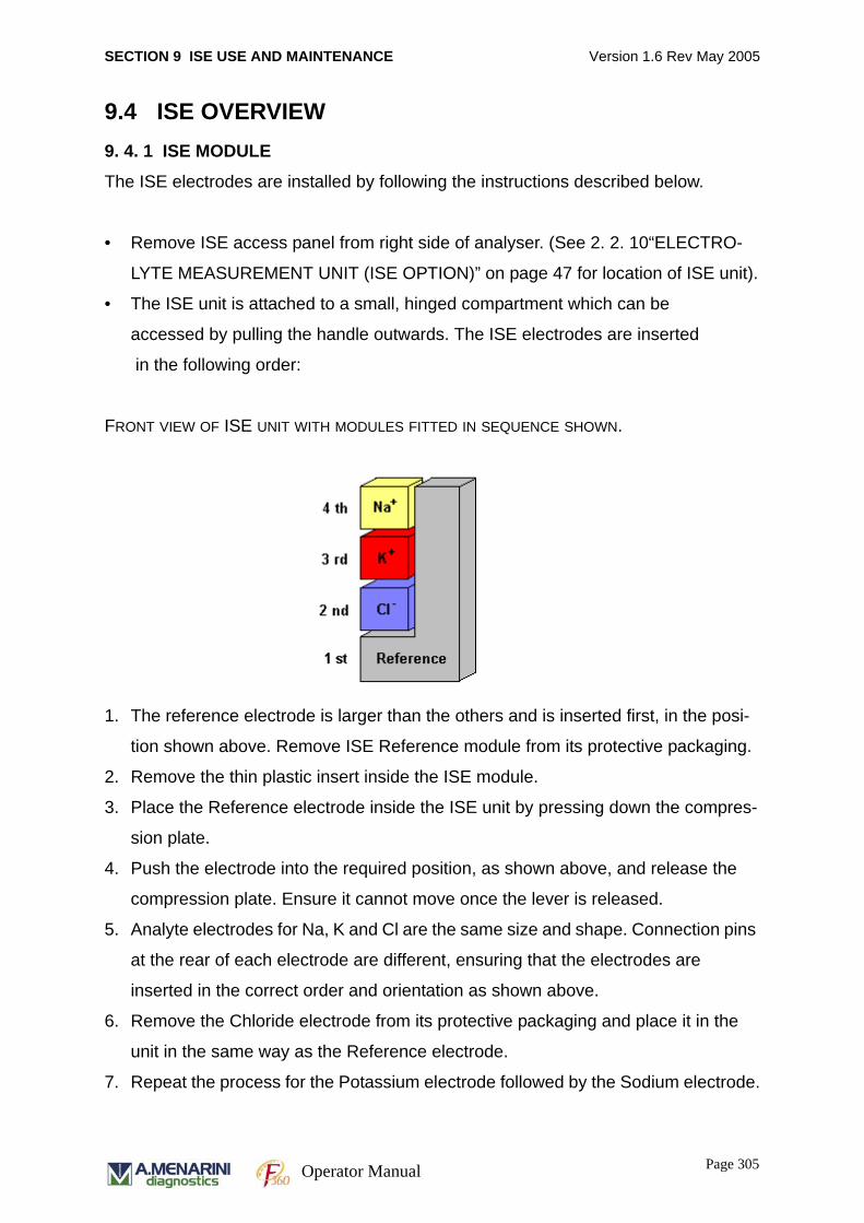
SECTION 9 ISE USE AND MAINTENANCE Version 1.6 Rev May 2005
9.4 ISE OVERVIEW9. 4. 1 ISE MODULE
The ISE electrodes are installed by following the instructions described below.
• Remove ISE access panel from right side of analyser. (See 2. 2. 10“ELECTRO-
LYTE MEASUREMENT UNIT (ISE OPTION)” on page 47 for location of ISE unit).
• The ISE unit is attached to a small, hinged compartment which can be
accessed by pulling the handle outwards. The ISE electrodes are inserted
in the following order:
FRONT VIEW OF ISE UNIT WITH MODULES FITTED IN SEQUENCE SHOWN.
1. The reference electrode is larger than the others and is inserted first, in the posi-
tion shown above. Remove ISE Reference module from its protective packaging.
2. Remove the thin plastic insert inside the ISE module.
3. Place the Reference electrode inside the ISE unit by pressing down the compres-
sion plate.
4. Push the electrode into the required position, as shown above, and release the
compression plate. Ensure it cannot move once the lever is released.
5. Analyte electrodes for Na, K and Cl are the same size and shape. Connection pins
at the rear of each electrode are different, ensuring that the electrodes are
inserted in the correct order and orientation as shown above.
6. Remove the Chloride electrode from its protective packaging and place it in the
unit in the same way as the Reference electrode.
7. Repeat the process for the Potassium electrode followed by the Sodium electrode.
Page 305Operator Manual
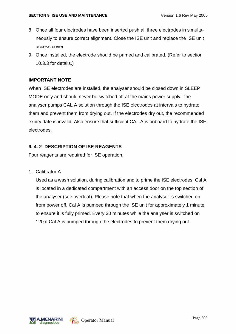
SECTION 9 ISE USE AND MAINTENANCE Version 1.6 Rev May 2005
8. Once all four electrodes have been inserted push all three electrodes in simulta-
neously to ensure correct alignment. Close the ISE unit and replace the ISE unit
access cover.
9. Once installed, the electrode should be primed and calibrated. (Refer to section
10.3.3 for details.)
IMPORTANT NOTE
When ISE electrodes are installed, the analyser should be closed down in SLEEP
MODE only and should never be switched off at the mains power supply. The
analyser pumps CAL A solution through the ISE electrodes at intervals to hydrate
them and prevent them from drying out. If the electrodes dry out, the recommended
expiry date is invalid. Also ensure that sufficient CAL A is onboard to hydrate the ISE
electrodes.
9. 4. 2 DESCRIPTION OF ISE REAGENTS
Four reagents are required for ISE operation.
1. Calibrator A
Used as a wash solution, during calibration and to prime the ISE electrodes. Cal A
is located in a dedicated compartment with an access door on the top section of
the analyser (see overleaf). Please note that when the analyser is switched on
from power off, Cal A is pumped through the ISE unit for approximately 1 minute
to ensure it is fully primed. Every 30 minutes while the analyser is switched on
120μl Cal A is pumped through the electrodes to prevent them drying out.
Page 306Operator Manual
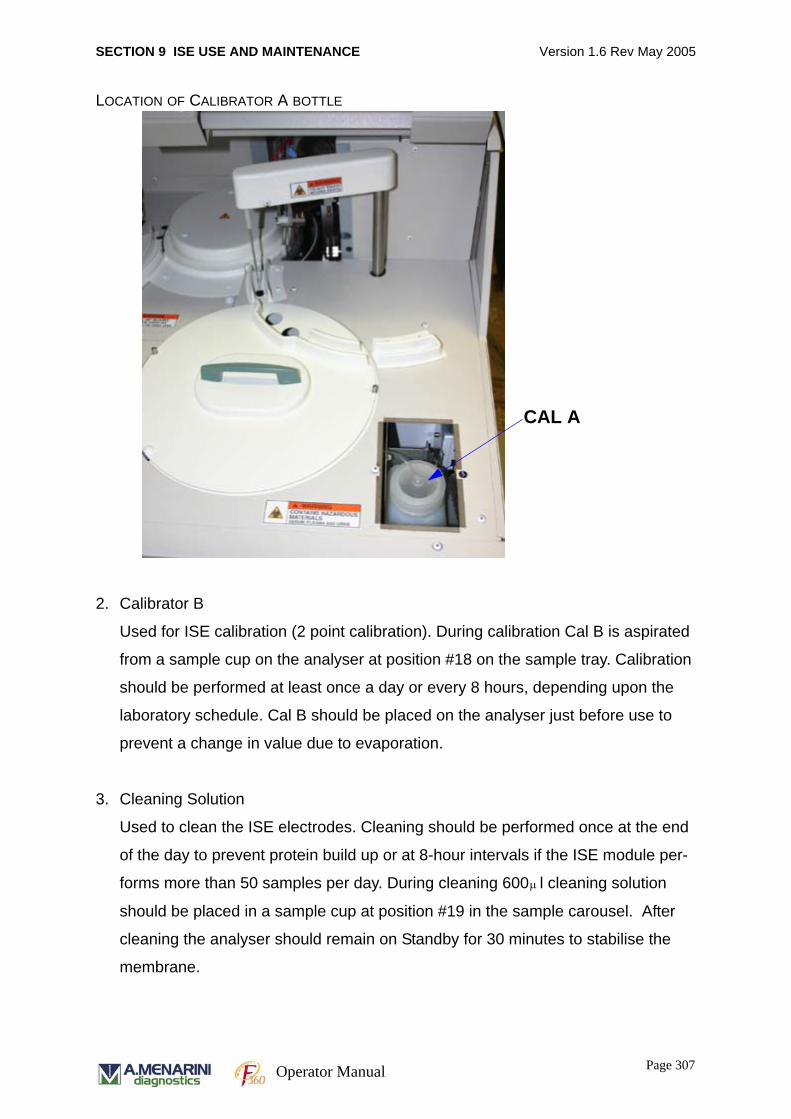
SECTION 9 ISE USE AND MAINTENANCE Version 1.6 Rev May 2005
LOCATION OF CALIBRATOR A BOTTLE
2. Calibrator B
Used for ISE calibration (2 point calibration). During calibration Cal B is aspirated
from a sample cup on the analyser at position #18 on the sample tray. Calibration
should be performed at least once a day or every 8 hours, depending upon the
laboratory schedule. Cal B should be placed on the analyser just before use to
prevent a change in value due to evaporation.
3. Cleaning Solution
Used to clean the ISE electrodes. Cleaning should be performed once at the end
of the day to prevent protein build up or at 8-hour intervals if the ISE module per-
forms more than 50 samples per day. During cleaning 600 l cleaning solution
should be placed in a sample cup at position #19 in the sample carousel. After
cleaning the analyser should remain on Standby for 30 minutes to stabilise the
membrane.
CAL A
μ
Page 307Operator Manual
SECTION 9 ISE USE AND MAINTENANCE Version 1.6 Rev May 2005
4. Urine Diluent
Urine samples are automatically diluted by a factor of 11 with urine diluent prior to
measurement. Urine diluent is located in a reagent position in the RCU tray and
should be registered as a reagent in the [System Parameters][System (F9)]
screen. A volume of 315μl is dispensed into a cuvette in the IRU where the dilution
takes place. The diluted sample is then dispensed into the ISE module.
9. 4. 3 STORAGE AND USAGE OF ISE REAGENTS
All ISE reagents should be stored in a cool dark environment. Cal B and ISE Cleaning
Solution should be dispensed from their containers just before use and once used
should not be kept since evaporation will alter the concentration of the solutions.
Reagents past the expiry date must never be used.
When using a new bottle of any reagent be careful never to mix it with the old
solution. Cal A bottle should be gently agitated before use to ensure it is
homogeneous.
9. 4. 4 ISE UNIT POWER OFF
Since Cal A is pumped through the electrodes every 30 minutes it isn’t recommended
to switch the analyser power off for any extended periods. At the end of the day the
analyser should be placed into sleep mode as described in section 3.2.11 so that Cal
A is pumped through the electrodes every 30 minutes. If the electrodes are kept for
over 2 hours without regular Cal A flow then it is possible for Na+ ions to pass from
the reference electrode into the Na electrode and affect sodium measurement.
If the ISE unit is switched off for more than 2 hours then the procedure below should
be followed to ensure correct storage of the electrode.
9. 4. 5 ISE MODULE STORAGE
If the ISE module is switched off for over 2 hours for any reason perform the following
steps to prevent the electrodes from drying out.
1. Unscrew Cal A bottle cap
Page 308Operator Manual
SECTION 9 ISE USE AND MAINTENANCE Version 1.6 Rev May 2005
2. Prime ISE 10 times from [Maintenance][Sequence(F9)] screen
3. Remove all electrodes from ISE unit (see Section 10.3.10). Place Na, Cl and Ref
electrodes into individual sealed bags. Inject Cal A into the lumen of the K elec-
trode and seal both sides of electrode with cellophane to ensure Cal A is retained.
Place K electrode into a sealed bag.
4. Remove Calibrator A bottle from the analyser and discard if storage period is
greater than the on board stability.
9. 4. 6 LOADING CALIBRATOR A
Calibrator A is loaded on the analyser using the following instructions.
• Remove Calibrator A access panel from top right of the analyser by loosening the
M3 screw and pulling the plastic clip.
• Remove tube and attached lid from existing Cal A bottle if present, ensuring any
remaining liquid on the lid is removed and insert the new bottle of Calibrator A into
the CAL A section of the ISE unit.
• Place the feed tube from the pump into the Calibrator A bottle. Screw on the bottle
cap attached to the feed tube, and ensure that the feed tube is touching the bot-
tom of the container.
• Reset working hour counter for Calibrant A in the [Maintenance][Wash (F10)]
screen
• Perform ISE prime in the [Maintenance][Sequence (F9)] screen 10 times to
ensure that the new Cal A has been thoroughly primed through the unit.
DO NOT MIX OLD CALIBRANT A SOLUTION WITH NEW SOLUTION. AFTER
CHANGING CALIBRANT A SOLUTION PRIME THE ISE 10 TIMES. WIPE ANY
MOISTURE ON THE CALIBRANT A BOTTLE CAP WITH CLEAN GAUZE.
9. 4. 7 ISE OPERATING CYCLES
The electrolyte measurement system performs 8 cycles.
Page 309Operator Manual
SECTION 9 ISE USE AND MAINTENANCE Version 1.6 Rev May 2005
Serum sample cycle
Calibrator A is pumped out of the electrodes, and sample is pumped in from the
sample port. The module acquires a sample reading, pumps Calibrator A to flush the
electrodes, and then acquires a Cal A reading.
Urine sample cycle
Calibrator A is pumped out of the electrodes, and a diluted urine sample is pumped in
from the sample port. Module acquires sample reading, pumps Calibrator A to flush
the electrodes, acquires a Cal A reading. The software then calculates the patient
result accounting for the 1+10 dilution.
Calibration cycle
Calibrator A is pumped from the electrodes. Module pumps Calibrator B from sample
port to the ion selective electrodes, acquires Calibrator B reading, pumps Calibrator A
to flush the ion selective electrodes, and then acquires a Calibrator A reading. The
software calculates the slope (S) from the two readings.
Prime cycle
Purges air from the electrodes by pumping Calibrator A from the container until
Calibrator A fills the lumens of all electrodes. Several cycles may be required to fully
purge air from the fluid lines.
Electrode exchange
Purges all fluid from the ISE module to allow removal of electrodes without fluid spills.
The cycle disables the automatic sipping (Stand-by cycle).
ISE Cleaning cycle
Pumps cleaning solution from the sample port into the ISE electrode, until cleaning is
complete. Pumps Calibrator A to flush ion selective electrodes, and then acquires a
Cal A reading.
Page 310Operator Manual
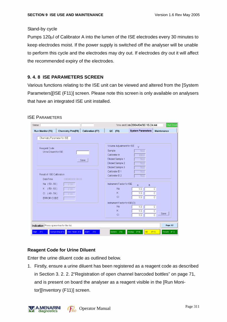
SECTION 9 ISE USE AND MAINTENANCE Version 1.6 Rev May 2005
Stand-by cycle
Pumps 120μl of Calibrator A into the lumen of the ISE electrodes every 30 minutes to
keep electrodes moist. If the power supply is switched off the analyser will be unable
to perform this cycle and the electrodes may dry out. If electrodes dry out it will affect
the recommended expiry of the electrodes.
9. 4. 8 ISE PARAMETERS SCREEN
Various functions relating to the ISE unit can be viewed and altered from the [System
Parameters][ISE (F11)] screen. Please note this screen is only available on analysers
that have an integrated ISE unit installed.
ISE PARAMETERS
Reagent Code for Urine Diluent
Enter the urine diluent code as outlined below.
1. Firstly, ensure a urine diluent has been registered as a reagent code as described
in Section 3. 2. 2. 2“Registration of open channel barcoded bottles” on page 71,
and is present on board the analyser as a reagent visible in the [Run Moni-
tor][Inventory (F11)] screen.
Page 311Operator Manual
SECTION 9 ISE USE AND MAINTENANCE Version 1.6 Rev May 2005
2. Go to [System Parameters][ISE (F11)] screen shown above.
3. Click on the field entitled ‘Urine Diluent for ISE’. Press SPACE bar and select the
ISE diluent, code [ISEDIL] using a double click on the required field. Click SAVE to
store the settings.
ISE Calibration
The results of the last ISE calibration along with error codes are displayed in this
screen.
Volume Adjustment for ISE
This is not accessible for the user and cannot be altered.
Instrument Factor for ISE
The operator can input linear correction factors for ISE and ISE diluent to adjust for
small variations between different analyser systems.
9. 4. 9 ISE PARAMETERS SCREEN -2
The normal range of the ISE measurements can be set using Page 2/2 function on
the ISE parameters screen.
Page 312Operator Manual
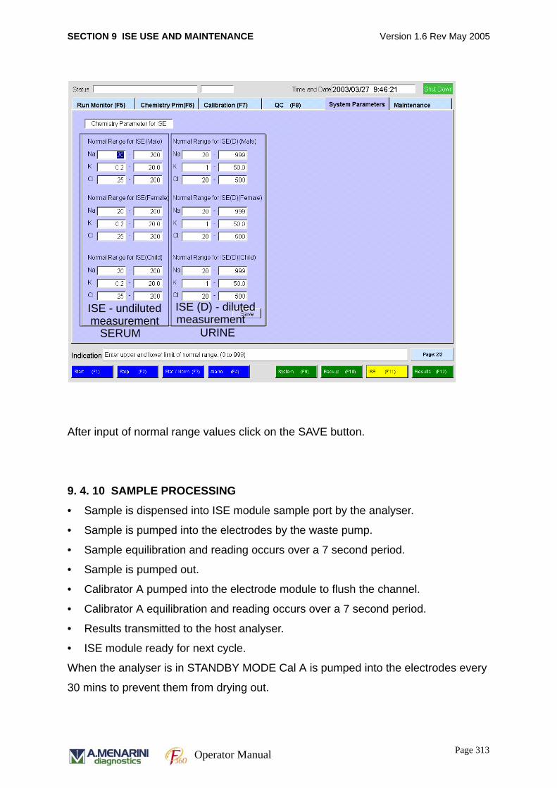
SECTION 9 ISE USE AND MAINTENANCE Version 1.6 Rev May 2005
After input of normal range values click on the SAVE button.
9. 4. 10 SAMPLE PROCESSING
• Sample is dispensed into ISE module sample port by the analyser.
• Sample is pumped into the electrodes by the waste pump.
• Sample equilibration and reading occurs over a 7 second period.
• Sample is pumped out.
• Calibrator A pumped into the electrode module to flush the channel.
• Calibrator A equilibration and reading occurs over a 7 second period.
• Results transmitted to the host analyser.
• ISE module ready for next cycle.
When the analyser is in STANDBY MODE Cal A is pumped into the electrodes every
30 mins to prevent them from drying out.
ISE - undiluted ISE (D) - diluted measurement measurement
SERUM URINE
Page 313Operator Manual
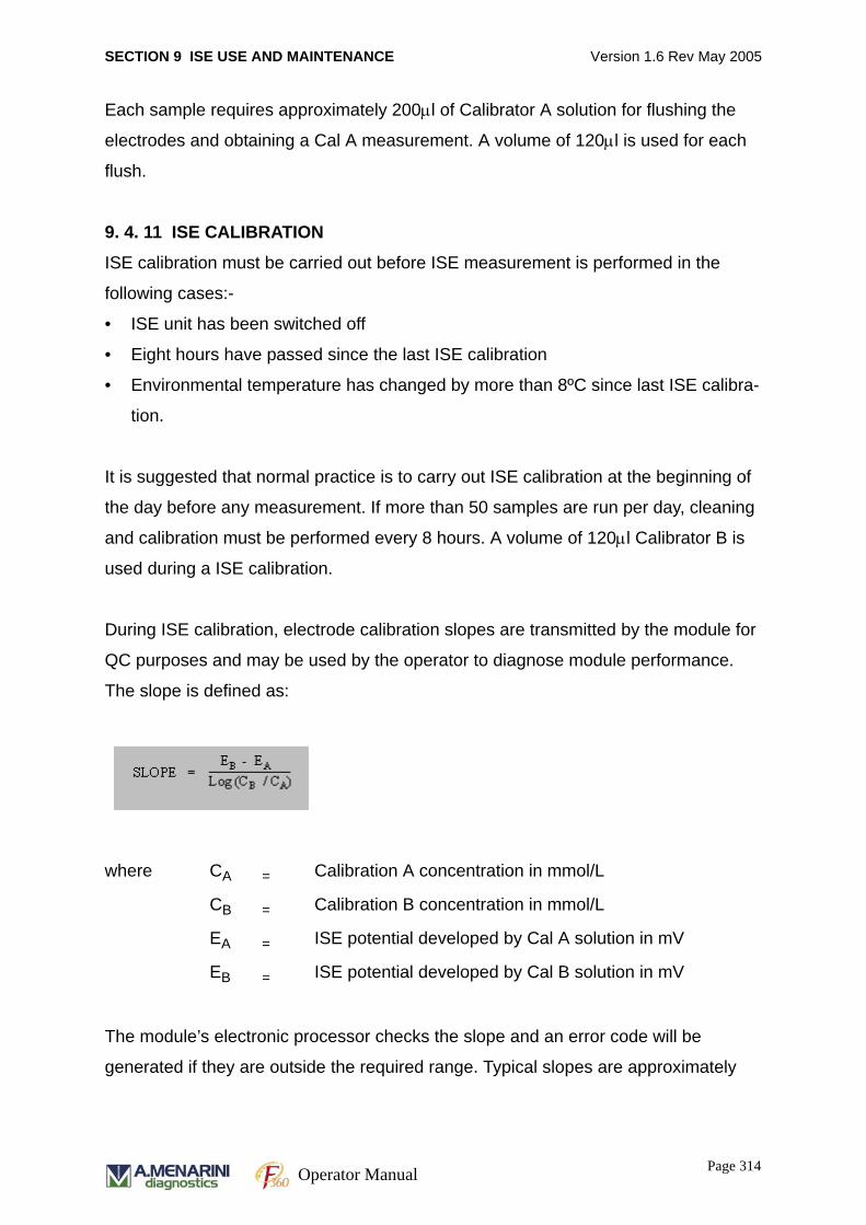
SECTION 9 ISE USE AND MAINTENANCE Version 1.6 Rev May 2005
Each sample requires approximately 200μl of Calibrator A solution for flushing the
electrodes and obtaining a Cal A measurement. A volume of 120μl is used for each
flush.
9. 4. 11 ISE CALIBRATION
ISE calibration must be carried out before ISE measurement is performed in the
following cases:-
• ISE unit has been switched off
• Eight hours have passed since the last ISE calibration
• Environmental temperature has changed by more than 8ºC since last ISE calibra-
tion.
It is suggested that normal practice is to carry out ISE calibration at the beginning of
the day before any measurement. If more than 50 samples are run per day, cleaning
and calibration must be performed every 8 hours. A volume of 120μl Calibrator B is
used during a ISE calibration.
During ISE calibration, electrode calibration slopes are transmitted by the module for
QC purposes and may be used by the operator to diagnose module performance.
The slope is defined as:
where CA = Calibration A concentration in mmol/L
CB = Calibration B concentration in mmol/L
EA = ISE potential developed by Cal A solution in mV
EB = ISE potential developed by Cal B solution in mV
The module’s electronic processor checks the slope and an error code will be
generated if they are outside the required range. Typical slopes are approximately
Page 314Operator Manual
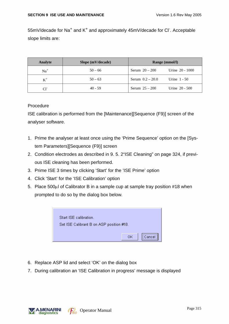
SECTION 9 ISE USE AND MAINTENANCE Version 1.6 Rev May 2005
55mV/decade for Na+ and K+ and approximately 45mV/decade for Cl-. Acceptable
slope limits are:
Procedure
ISE calibration is performed from the [Maintenance][Sequence (F9)] screen of the
analyser software.
1. Prime the analyser at least once using the ‘Prime Sequence’ option on the [Sys-
tem Parameters][Sequence (F9)] screen
2. Condition electrodes as described in 9. 5. 2“ISE Cleaning” on page 324, if previ-
ous ISE cleaning has been performed.
3. Prime ISE 3 times by clicking ‘Start’ for the ’ISE Prime’ option
4. Click ‘Start’ for the ‘ISE Calibration’ option
5. Place 500μl of Calibrator B in a sample cup at sample tray position #18 when
prompted to do so by the dialog box below.
6. Replace ASP lid and select ‘OK’ on the dialog box
7. During calibration an ‘ISE Calibration in progress’ message is displayed
Analyte Slope (mV/decade) Range (mmol/l)
Na+ 50 – 66 Serum 20 – 200 Urine 20 - 1000
K+ 50 – 63 Serum 0.2 – 20.0 Urine 1 - 50
Cl- 40 - 59 Serum 25 – 200 Urine 20 - 500
Page 315Operator Manual

SECTION 9 ISE USE AND MAINTENANCE Version 1.6 Rev May 2005
8. Once this message disappears the results of the ISE calibration are automatically
printed (if result printout is enabled) and can be viewed on the [System Parame-
ters][ISE (F11)] screen.
9. Check the calibration falls within the acceptable limits shown on the software (also
see above) and there are no error codes (0000 means no error).
10.Repeat ISE calibration until two consecutive measurements display no errors and
the values fall within 2.0 units.
9. 4. 12 REPLACING CALIBRATOR A REAGENT
Follow the procedure shown below to exchange the ISE Calibrant A bottle.
Procedure for exchange1. Take off the cover from the Cal A tank located on the right side of the upper panel
by removing a M3 screw and a latch.
2. Replace Calibrant-A bottle, place the feed tube in the bottle and screw on the
attached cap.
3. Go to MAINTENANCE / WASH (F10) in the software screen.
4. Click on the RESTART button adjacent to Calibrant A.
D200-0256
Page 316Operator Manual
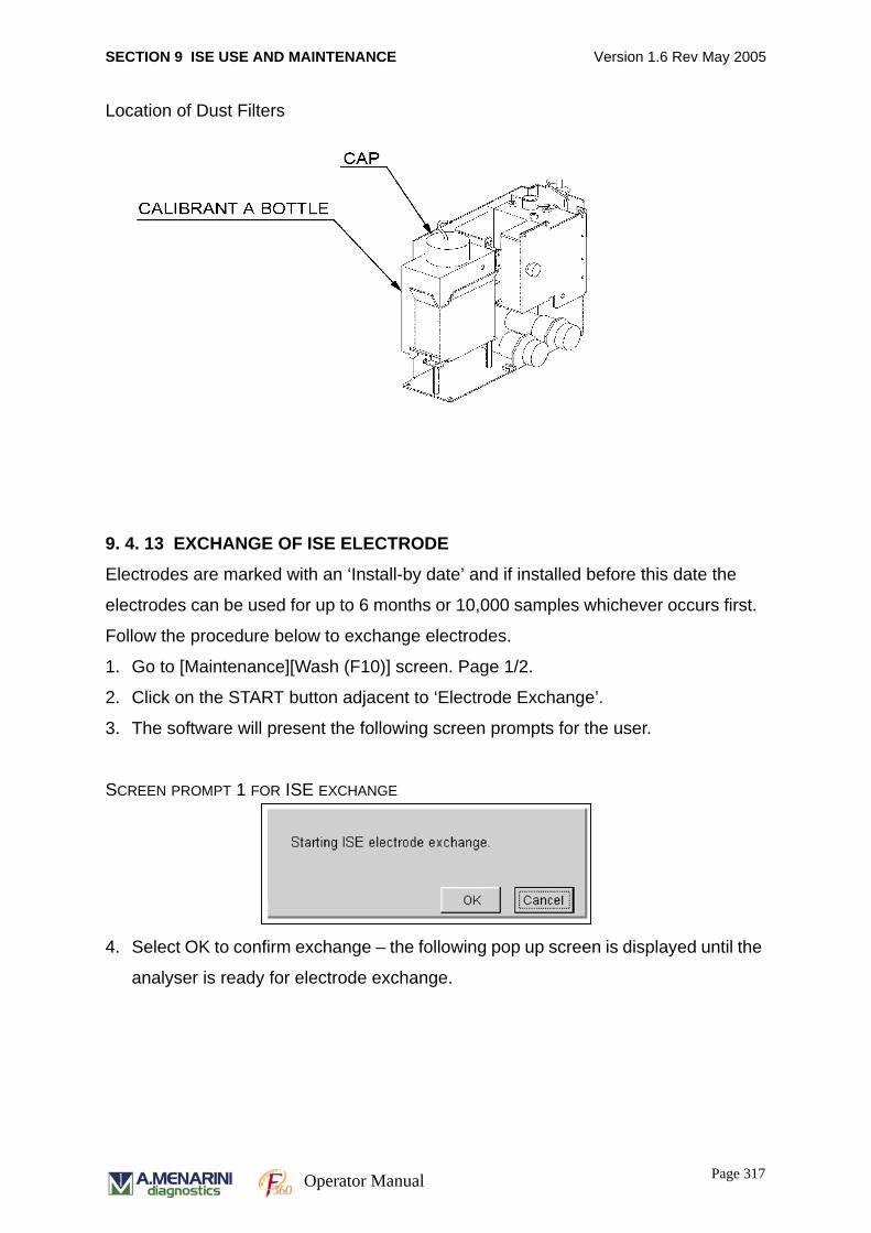
SECTION 9 ISE USE AND MAINTENANCE Version 1.6 Rev May 2005
Location of Dust Filters
9. 4. 13 EXCHANGE OF ISE ELECTRODE
Electrodes are marked with an ‘Install-by date’ and if installed before this date the
electrodes can be used for up to 6 months or 10,000 samples whichever occurs first.
Follow the procedure below to exchange electrodes.
1. Go to [Maintenance][Wash (F10)] screen. Page 1/2.
2. Click on the START button adjacent to ‘Electrode Exchange’.
3. The software will present the following screen prompts for the user.
SCREEN PROMPT 1 FOR ISE EXCHANGE
4. Select OK to confirm exchange – the following pop up screen is displayed until the
analyser is ready for electrode exchange.
Page 317Operator Manual
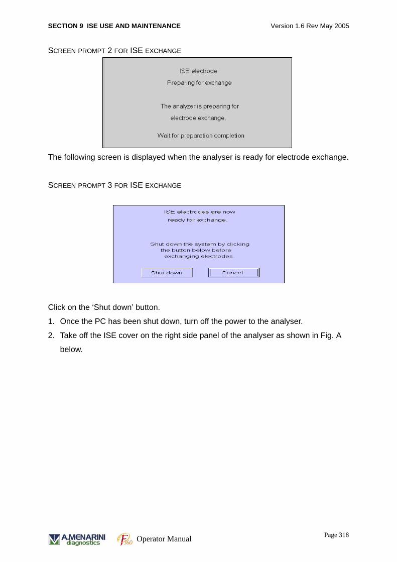
SECTION 9 ISE USE AND MAINTENANCE Version 1.6 Rev May 2005
SCREEN PROMPT 2 FOR ISE EXCHANGE
The following screen is displayed when the analyser is ready for electrode exchange.
SCREEN PROMPT 3 FOR ISE EXCHANGE
Click on the ‘Shut down’ button.
1. Once the PC has been shut down, turn off the power to the analyser.
2. Take off the ISE cover on the right side panel of the analyser as shown in Fig. A
below.
Page 318Operator Manual
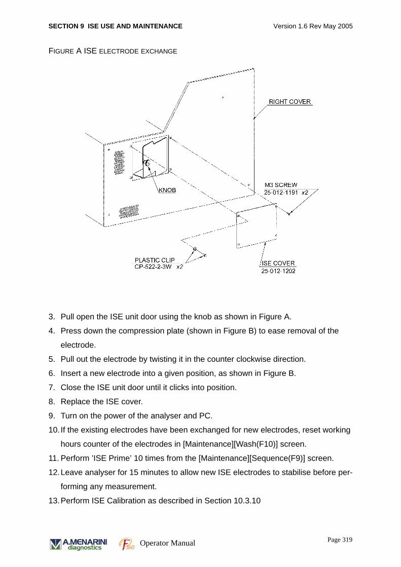
SECTION 9 ISE USE AND MAINTENANCE Version 1.6 Rev May 2005
FIGURE A ISE ELECTRODE EXCHANGE
3. Pull open the ISE unit door using the knob as shown in Figure A.
4. Press down the compression plate (shown in Figure B) to ease removal of the
electrode.
5. Pull out the electrode by twisting it in the counter clockwise direction.
6. Insert a new electrode into a given position, as shown in Figure B.
7. Close the ISE unit door until it clicks into position.
8. Replace the ISE cover.
9. Turn on the power of the analyser and PC.
10. If the existing electrodes have been exchanged for new electrodes, reset working
hours counter of the electrodes in [Maintenance][Wash(F10)] screen.
11. Perform ’ISE Prime’ 10 times from the [Maintenance][Sequence(F9)] screen.
12.Leave analyser for 15 minutes to allow new ISE electrodes to stabilise before per-
forming any measurement.
13.Perform ISE Calibration as described in Section 10.3.10
Page 319Operator Manual
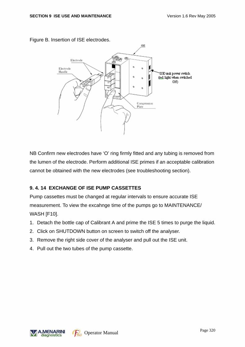
SECTION 9 ISE USE AND MAINTENANCE Version 1.6 Rev May 2005
Figure B. Insertion of ISE electrodes.
NB Confirm new electrodes have ‘O’ ring firmly fitted and any tubing is removed from
the lumen of the electrode. Perform additional ISE primes if an acceptable calibration
cannot be obtained with the new electrodes (see troubleshooting section).
9. 4. 14 EXCHANGE OF ISE PUMP CASSETTES
Pump cassettes must be changed at regular intervals to ensure accurate ISE
measurement. To view the excahnge time of the pumps go to MAINTENANCE/
WASH [F10].
1. Detach the bottle cap of Calibrant A and prime the ISE 5 times to purge the liquid.
2. Click on SHUTDOWN button on screen to switch off the analyser.
3. Remove the right side cover of the analyser and pull out the ISE unit.
4. Pull out the two tubes of the pump cassette.
Page 320Operator Manual
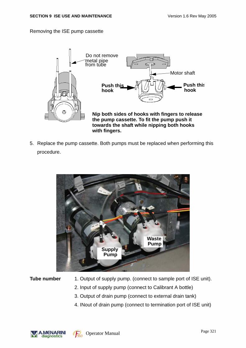
SECTION 9 ISE USE AND MAINTENANCE Version 1.6 Rev May 2005
Removing the ISE pump cassette
5. Replace the pump cassette. Both pumps must be replaced when performing this
procedure.
Tube number 1. Output of supply pump. (connect to sample port of ISE unit).
2. Input of supply pump (connect to Calibrant A bottle)
3. Output of drain pump (connect to external drain tank)
4. INout of drain pump (connect to termination port of ISE unit)
Do not remove metal pipe from tube
Motor shaft
Push thishookhook
Push this
Nip both sides of hooks with fingers to releasethe pump cassette. To fit the pump push it towards the shaft while nipping both hooks with fingers.
1 2
3 4
WastePump
SupplyPump
Page 321Operator Manual
SECTION 9 ISE USE AND MAINTENANCE Version 1.6 Rev May 2005
6. Attach the bottle cap for Calibrant A, turn the analyser power on and prime 10
times. During priming check that the fluid flows correctly into each tube and that
there are no leakages.
7. Reset the working hours of the pump cassette in the Maintenance/ WASH (F10) /
Page 2/2.
Page 322Operator Manual
SECTION 9 ISE USE AND MAINTENANCE Version 1.6 Rev May 2005
9.5 ISE MAINTENANCECorrect maintenance procedures should be followed to ensure optimal performance
of ISE electrodes.
• When properly maintained, each ISE can analyse up to 10,000 samples.
• Cleaning solution, aspirated from the sample cup in position #19, is used at least
once a day at the end of each day.
• An ISE calibration should be performed every 8 hours.
• If the ISE is performing more than 50 samples per day, then the cleaning proce-
dure should be performed every 8 hours if QC
• The entire double junction electrode is disposable. The reference electrode is
filled with sufficient KCl to ensure that no refilling of the solution is required
throughout the lifetime of the electrode.
• Electrodes require a Cal A flush every 30 minutes
• Urine samples are automatically diluted 1+10 before measurement.
• The ISE module is not refrigerated. Therefore, the operator must ensure that the
ambient temperature does not exceed 38ºC.
• Sampling port should be kept free from crystalline depositsat at all timesas these
can adversely affect the results.
9. 5. 1 MAINTENANCE SCHEDULE
The ISE module requires minimal operator maintenance and the only daily
maintenance is the cleaning procedure at the end of each day. Recommendations for
replacement of expendable items are listed below.
Page 323Operator Manual
SECTION 9 ISE USE AND MAINTENANCE Version 1.6 Rev May 2005
RECOMMENDED MAINTENANCE/REPLACEMENT INTERVALS
Pump cassette 9 months
Na Electrode 6 months
K electrode 6 months
Cl electrode 6 months
Ref. electrode 6 months
Reagent Refill as necessary
HIGH VOLUME USER
Pump cassette 6 months
Na Electrode 10,000 samples
K electrode 10,000 samples
Cl electrode 10,000 samples
Ref. electrode 10,000 samples
Reagent Refill as necessary
9. 5. 2 ISE CLEANING
ISE unit requires cleaning at least once a day or every 8 hours if the number of
samples measured is greater than 50 to prevent protein build up. It is recommended
that the cleaning procedure be performed at the end of the day to avoid down time
since the electrodes must be left to stabilise for 30 minutes after the cleaning
procedure. During this 30 min period it is recommended that the electrodes are
‘conditioned’ by performing ISE measurements on any control serum. The values of
this measurement are not significant. The purpose of the conditioning is to establish a
fine layer of protein over the ISE electrode membranes. Start ISE cleaning as
follows:-
1. Go to the [System Parameters][Sequence (F9)] screen
2. Click on ‘Start’ for the ‘ISE Cleaning’ option
3. Place 600 l of ISE Cleaning solution in a sample cup at sample tray position #19
when prompted to do so by the dialog box below.
μ
Page 324Operator Manual
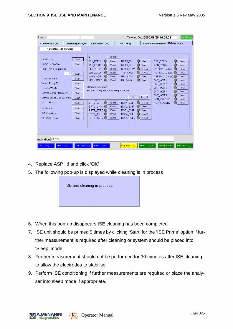
SECTION 9 ISE USE AND MAINTENANCE Version 1.6 Rev May 2005
4. Replace ASP lid and click ‘OK’
5. The following pop-up is displayed while cleaning is in process
6. When this pop-up disappears ISE cleaning has been completed
7. ISE unit should be primed 5 times by clicking ‘Start’ for the ‘ISE Prime’ option if fur-
ther measurement is required after cleaning or system should be placed into
‘Sleep’ mode.
8. Further measurement should not be performed for 30 minutes after ISE cleaning
to allow the electrodes to stabilise.
9. Perform ISE conditioning if further measurements are required or place the analy-
ser into sleep mode if appropriate.
Page 325Operator Manual
SECTION 9 ISE USE AND MAINTENANCE Version 1.6 Rev May 2005
ISE Conditioning
1. Load sample positions 1 - 5 with any control serum – the results are not significant
so any control serum may be used.
2. Go to [Run Monitor][Test Select (F11)] screen.
3. Select an ISE measurement to be performed as a normal (N) sample on each of
the samples in positions 1 - 5. See Sections 3.2.4 & 3.2.6 for full instructions on
test selection for barcoded and non-barcoded samples.
4. Press Start (F1).
5. Once analysis has been completed remove samples from the sample tray.
Page 326Operator Manual
SECTION 9 ISE USE AND MAINTENANCE Version 1.6 Rev May 2005
9.6 ERROR MESSAGES & ALARM CODESThis section provides a summary of the alarm codes that may appear on screen.
When an error or alarm occurs during operation, a reference can be made to the table
below. Contact the customer service department if necessary.
ISE UNIT ERROR CODES
E1775 //ISE ISE; Serum sample error
E1776 // ISE; Urine sample error
E1777 // ISE; no data
Page 327Operator Manual
SECTION 9 ISE USE AND MAINTENANCE Version 1.6 Rev May 2005
ISE MODULE ERROR CODES
Note-1: “S” = Sample
“A” = Calibrator A
“B” = Calibrator B
Note-2: When there is only a Na urine error and no out of range error, the error
code is “K”.
Cause Measurement Item Byte1 Byte2 Byte3 Byte4 Byte4
Noise or Air for-Sample or Calibrant-B
Noise or Air for Calibrant-A
Drift inCalibrant-A
Out of Rangefor-Sample orCalibrant-B or Urine
Noise,Drift orOut of Range
No error 0 0 0 0
Na 1 1 1 1
K 2 2 2 2
Na, K 3 3 3 3
Cl 4 4 4 4
Na, Cl 5 5 5 5
K, CL 6 6 6 6
Na, K, Cl 7 7 7 7
Air S or B(Note-1)
A(Note-1) -- --
Noise,Drift orOut of Range(Urine)
No error 0 0 0 0 K(Note-2)
Na 1 1 1 1 L
K 2 2 2 2 M
Na, K 3 3 3 3 N
Cl 4 4 4 4 O
Na, Cl 5 5 5 5 P
K, CL 6 6 6 6 Q
Na, K, Cl 7 7 7 7 R
SPT liquid detection error
9 9 9 7
SPT malfunction
9 9 9 8
Communication error
9 9 9 9
Page 328Operator Manual
SECTION 9 ISE USE AND MAINTENANCE Version 1.6 Rev May 2005
9.7 TROUBLESHOOTINGWhen troubleshooting the F360 ISE unit, the following initial checks should be carried
out:
• Correct electrode installation procedure has been followed
• ISE unit is receiving power from host analyser (check red LED is ON)
• Equipment is used according to the recommendations by trained personnel.
• System maintenance has been performed.
Please contact A. MENARINI Diagnostics Technical Support department if electrical
or mechanical system faults are identified. For safety reasons the user should NOT
carry out internal inspections of the analyser.
9. 7. 1 ANALYTICAL PROBLEMS
When contacting our Technical Support department for analytical troubleshooting
problems please have the following information available:
a. Analyser serial number
b. ISE unit serial number
c. Explanation of the problem
d. Serial number and lot number Reference, Na+, K+ and Cl- electrodes.
d. Serial number and lot number of Calibrator A and B, wash solution, diluent and
quality controls used.
e. Recent results of calibrations
f. Recent results of quality control samples
g. Measurement results.
For further investigation, refer to the following list after the above checks have been
completed.
Page 329Operator Manual
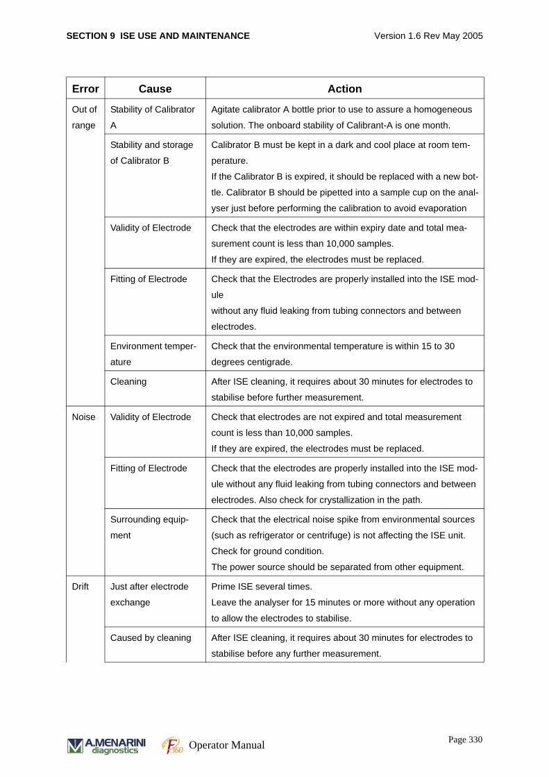
SECTION 9 ISE USE AND MAINTENANCE Version 1.6 Rev May 2005
Error Cause Action
Out of
range
Stability of Calibrator
A
Agitate calibrator A bottle prior to use to assure a homogeneous
solution. The onboard stability of Calibrant-A is one month.
Stability and storage
of Calibrator B
Calibrator B must be kept in a dark and cool place at room tem-
perature.
If the Calibrator B is expired, it should be replaced with a new bot-
tle. Calibrator B should be pipetted into a sample cup on the anal-
yser just before performing the calibration to avoid evaporation
Validity of Electrode Check that the electrodes are within expiry date and total mea-
surement count is less than 10,000 samples.
If they are expired, the electrodes must be replaced.
Fitting of Electrode Check that the Electrodes are properly installed into the ISE mod-
ule
without any fluid leaking from tubing connectors and between
electrodes.
Environment temper-
ature
Check that the environmental temperature is within 15 to 30
degrees centigrade.
Cleaning After ISE cleaning, it requires about 30 minutes for electrodes to
stabilise before further measurement.
Noise Validity of Electrode Check that electrodes are not expired and total measurement
count is less than 10,000 samples.
If they are expired, the electrodes must be replaced.
Fitting of Electrode Check that the electrodes are properly installed into the ISE mod-
ule without any fluid leaking from tubing connectors and between
electrodes. Also check for crystallization in the path.
Surrounding equip-
ment
Check that the electrical noise spike from environmental sources
(such as refrigerator or centrifuge) is not affecting the ISE unit.
Check for ground condition.
The power source should be separated from other equipment.
Drift Just after electrode
exchange
Prime ISE several times.
Leave the analyser for 15 minutes or more without any operation
to allow the electrodes to stabilise.
Caused by cleaning After ISE cleaning, it requires about 30 minutes for electrodes to
stabilise before any further measurement.
Page 330Operator Manual
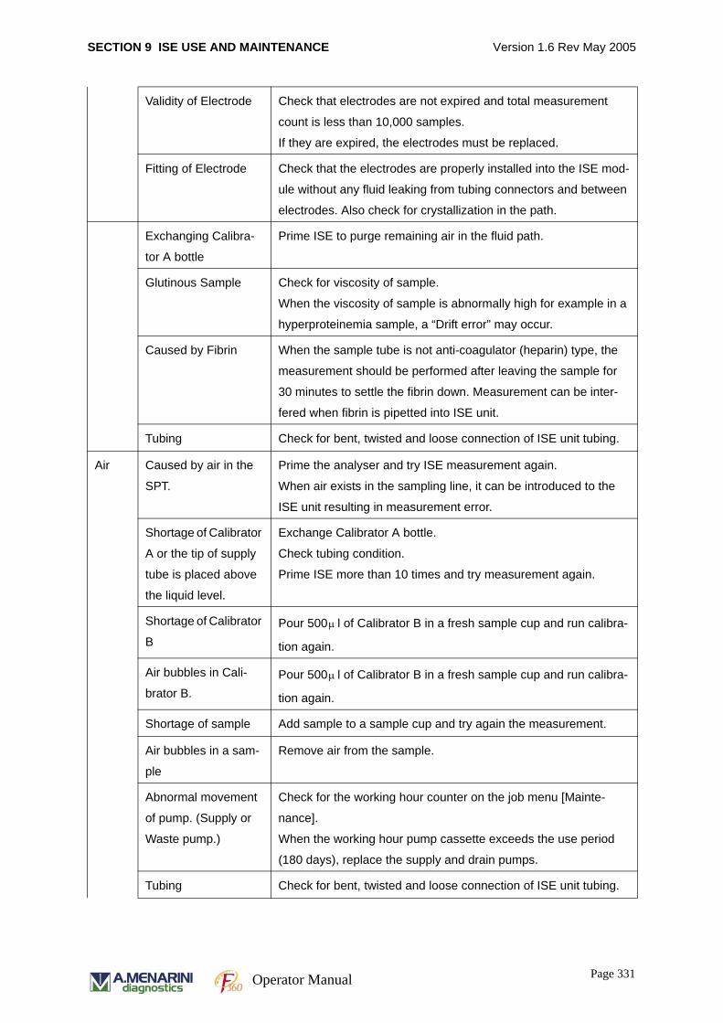
SECTION 9 ISE USE AND MAINTENANCE Version 1.6 Rev May 2005
Validity of Electrode Check that electrodes are not expired and total measurement
count is less than 10,000 samples.
If they are expired, the electrodes must be replaced.
Fitting of Electrode Check that the electrodes are properly installed into the ISE mod-
ule without any fluid leaking from tubing connectors and between
electrodes. Also check for crystallization in the path.
Exchanging Calibra-
tor A bottle
Prime ISE to purge remaining air in the fluid path.
Glutinous Sample Check for viscosity of sample.
When the viscosity of sample is abnormally high for example in a
hyperproteinemia sample, a “Drift error” may occur.
Caused by Fibrin When the sample tube is not anti-coagulator (heparin) type, the
measurement should be performed after leaving the sample for
30 minutes to settle the fibrin down. Measurement can be inter-
fered when fibrin is pipetted into ISE unit.
Tubing Check for bent, twisted and loose connection of ISE unit tubing.
Air Caused by air in the
SPT.
Prime the analyser and try ISE measurement again.
When air exists in the sampling line, it can be introduced to the
ISE unit resulting in measurement error.
Shortage of Calibrator
A or the tip of supply
tube is placed above
the liquid level.
Exchange Calibrator A bottle.
Check tubing condition.
Prime ISE more than 10 times and try measurement again.
Shortage of Calibrator
BPour 500 l of Calibrator B in a fresh sample cup and run calibra-
tion again.
Air bubbles in Cali-
brator B.Pour 500 l of Calibrator B in a fresh sample cup and run calibra-
tion again.
Shortage of sample Add sample to a sample cup and try again the measurement.
Air bubbles in a sam-
ple
Remove air from the sample.
Abnormal movement
of pump. (Supply or
Waste pump.)
Check for the working hour counter on the job menu [Mainte-
nance].
When the working hour pump cassette exceeds the use period
(180 days), replace the supply and drain pumps.
Tubing Check for bent, twisted and loose connection of ISE unit tubing.
μ
μ
Page 331Operator Manual
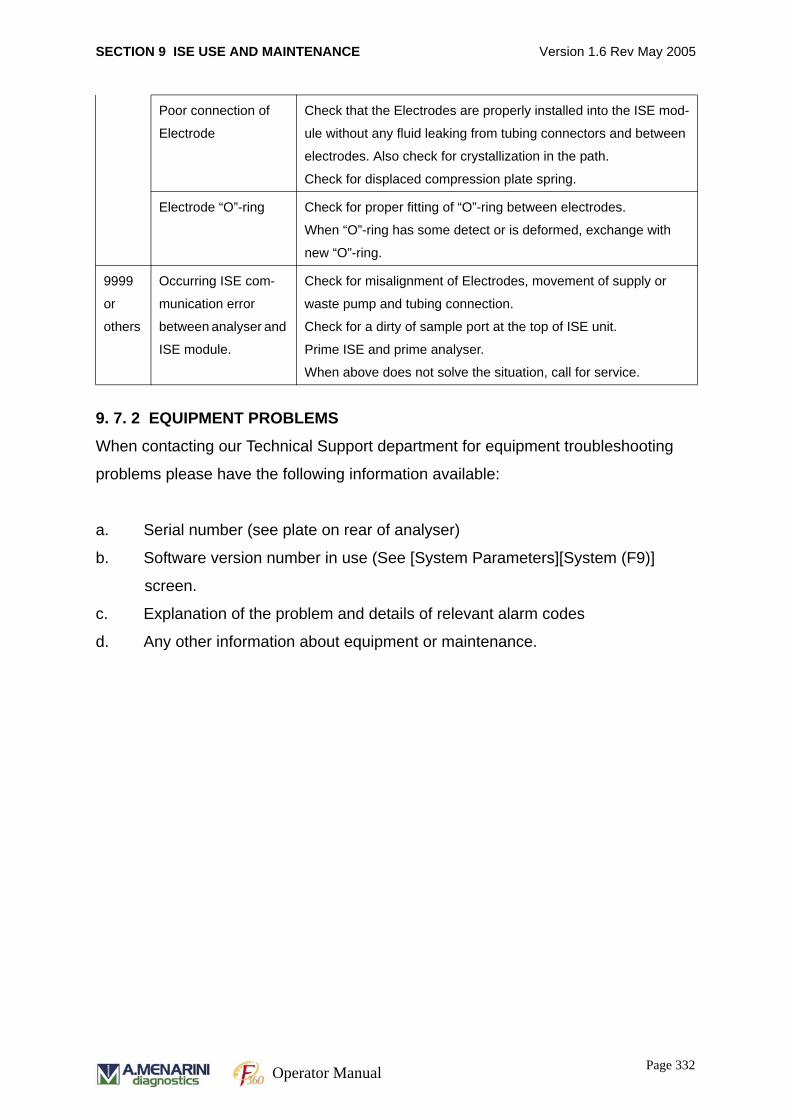
SECTION 9 ISE USE AND MAINTENANCE Version 1.6 Rev May 2005
9. 7. 2 EQUIPMENT PROBLEMS
When contacting our Technical Support department for equipment troubleshooting
problems please have the following information available:
a. Serial number (see plate on rear of analyser)
b. Software version number in use (See [System Parameters][System (F9)]
screen.
c. Explanation of the problem and details of relevant alarm codes
d. Any other information about equipment or maintenance.
Poor connection of
Electrode
Check that the Electrodes are properly installed into the ISE mod-
ule without any fluid leaking from tubing connectors and between
electrodes. Also check for crystallization in the path.
Check for displaced compression plate spring.
Electrode “O”-ring Check for proper fitting of “O”-ring between electrodes.
When “O”-ring has some detect or is deformed, exchange with
new “O”-ring.
9999
or
others
Occurring ISE com-
munication error
between analyser and
ISE module.
Check for misalignment of Electrodes, movement of supply or
waste pump and tubing connection.
Check for a dirty of sample port at the top of ISE unit.
Prime ISE and prime analyser.
When above does not solve the situation, call for service.
Page 332Operator Manual
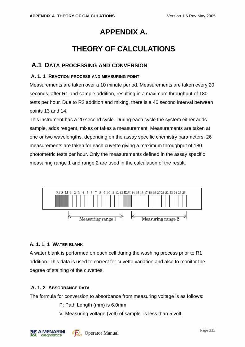
APPENDIX A THEORY OF CALCULATIONS Version 1.6 Rev May 2005
APPENDIX A.
THEORY OF CALCULATIONS
A.1 DATA PROCESSING AND CONVERSION
A. 1. 1 REACTION PROCESS AND MEASURING POINT
Measurements are taken over a 10 minute period. Measurements are taken every 20
seconds, after R1 and sample addition, resulting in a maximum throughput of 180
tests per hour. Due to R2 addition and mixing, there is a 40 second interval between
points 13 and 14.
This instrument has a 20 second cycle. During each cycle the system either adds
sample, adds reagent, mixes or takes a measurement. Measurements are taken at
one or two wavelengths, depending on the assay specific chemistry parameters. 26
measurements are taken for each cuvette giving a maximum throughput of 180
photometric tests per hour. Only the measurements defined in the assay specific
measuring range 1 and range 2 are used in the calculation of the result.
A. 1. 1. 1 WATER BLANK
A water blank is performed on each cell during the washing process prior to R1
addition. This data is used to correct for cuvette variation and also to monitor the
degree of staining of the cuvettes.
A. 1. 2 ABSORBANCE DATA
The formula for conversion to absorbance from measuring voltage is as follows:
P: Path Length (mm) is 6.0mm
V: Measuring voltage (volt) of sample is less than 5 volt
R1 S M 1 2 3 4 5 6 7
8 9 10 11 12 13 R2 M
14
15 16 17
Measuring range 1
18 20 19 25 24 23 22 21 26
Measuring range 2
Page 333Operator Manual
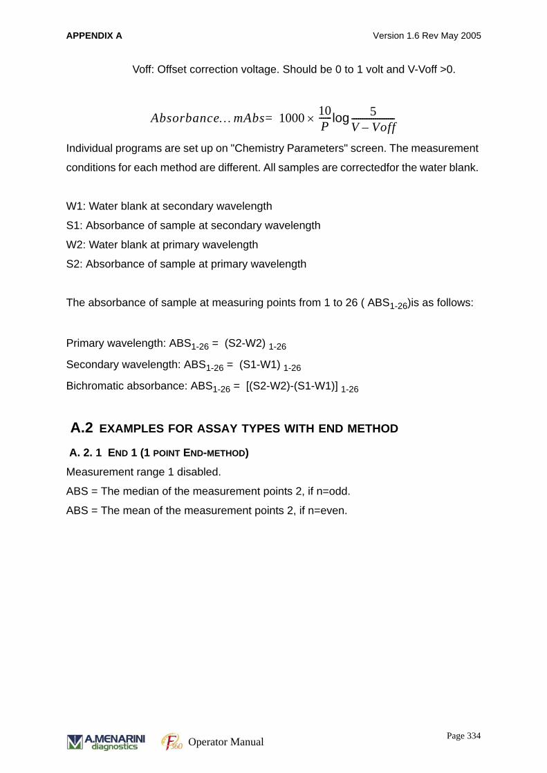
APPENDIX A Version 1.6 Rev May 2005
Voff: Offset correction voltage. Should be 0 to 1 volt and V-Voff >0.
Individual programs are set up on "Chemistry Parameters" screen. The measurement
conditions for each method are different. All samples are correctedfor the water blank.
W1: Water blank at secondary wavelength
S1: Absorbance of sample at secondary wavelength
W2: Water blank at primary wavelength
S2: Absorbance of sample at primary wavelength
The absorbance of sample at measuring points from 1 to 26 ( ABS1-26)is as follows:
Primary wavelength: ABS1-26 = (S2-W2) 1-26
Secondary wavelength: ABS1-26 = (S1-W1) 1-26
Bichromatic absorbance: ABS1-26 = [(S2-W2)-(S1-W1)] 1-26
A.2 EXAMPLES FOR ASSAY TYPES WITH END METHOD
A. 2. 1 END 1 (1 POINT END-METHOD)
Measurement range 1 disabled.
ABS = The median of the measurement points 2, if n=odd.
ABS = The mean of the measurement points 2, if n=even.
Absorbance…mAbs 1000 10P------× 5
V Voff–--------------------log=
Page 334Operator Manual
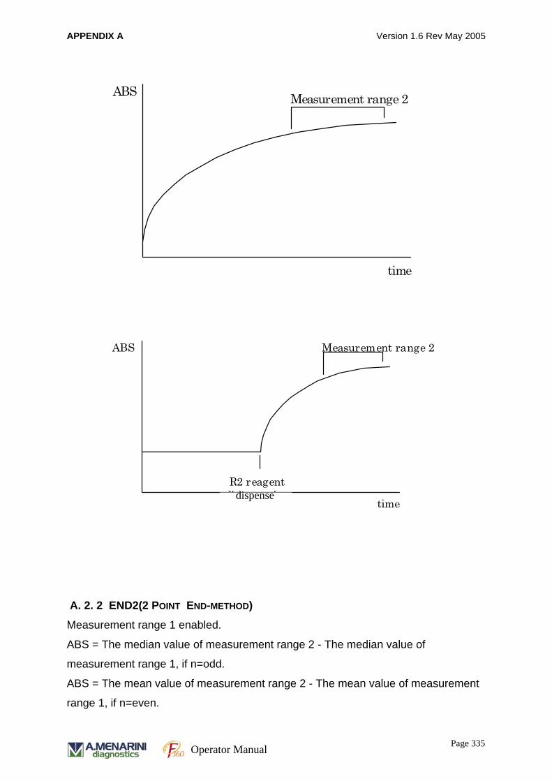
APPENDIX A Version 1.6 Rev May 2005
A. 2. 2 END2(2 POINT END-METHOD)
Measurement range 1 enabled.
ABS = The median value of measurement range 2 - The median value of
measurement range 1, if n=odd.
ABS = The mean value of measurement range 2 - The mean value of measurement
range 1, if n=even.
ABS
time
Measurement range 2
ABS
time
Measurement range 2
R2 reagent dispensation dispense
Page 335Operator Manual
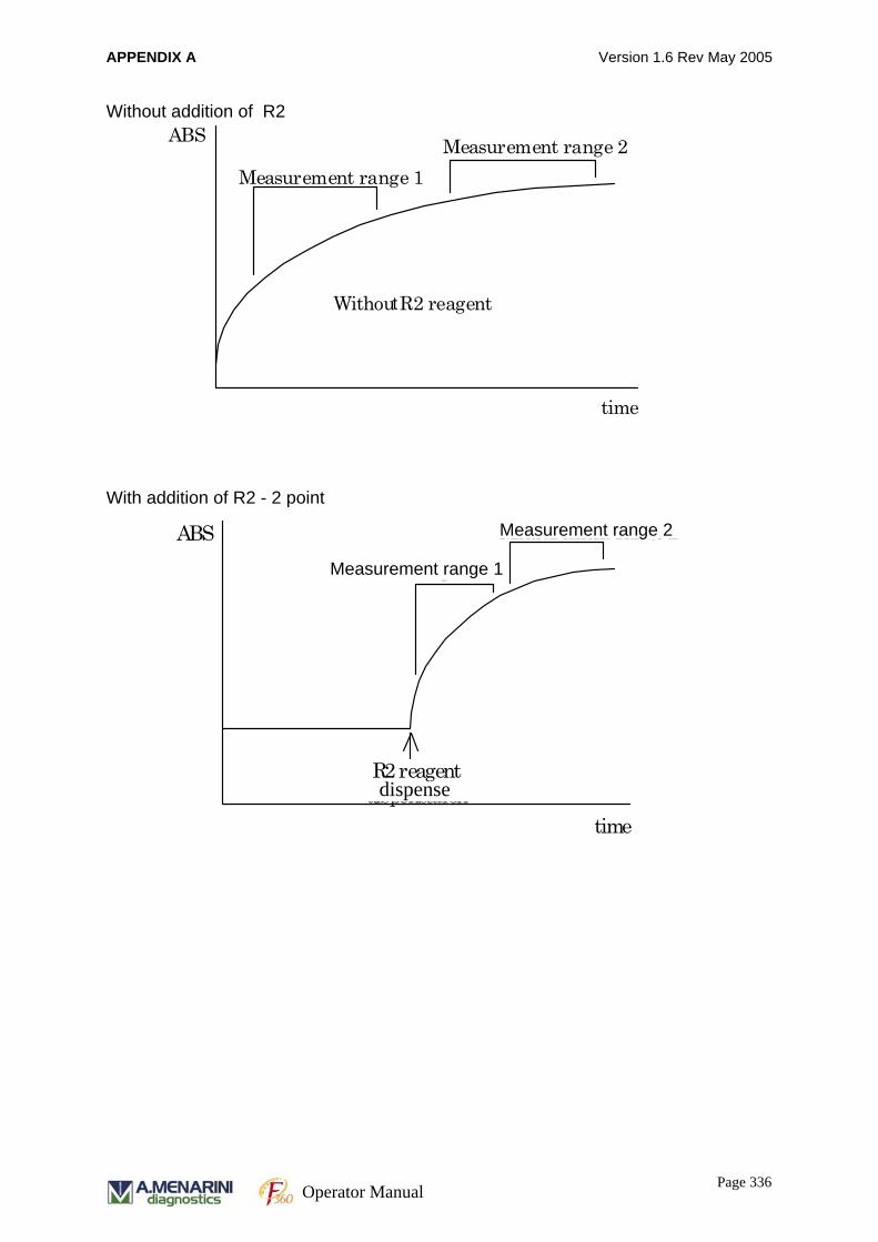
APPENDIX A Version 1.6 Rev May 2005
Without addition of R2
With addition of R2 - 2 point
ABS
time
Measurement range 2 Measurement range 1
Withou R2 reagent t
ABS
time
Measurement range 2 Measurement range 1
R2 reagent dispensation
Measurement range 2
Measurement range 1
dispense
Page 336Operator Manual
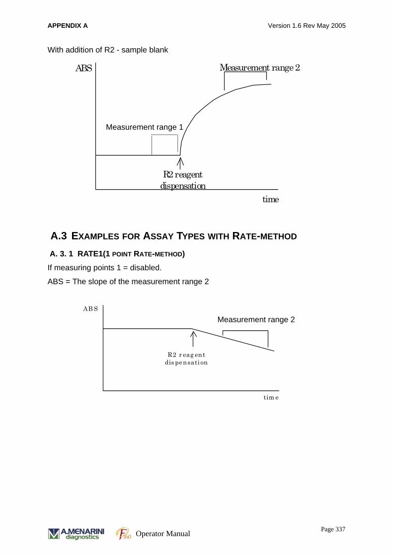
APPENDIX A Version 1.6 Rev May 2005
With addition of R2 - sample blank
A.3 EXAMPLES FOR ASSAY TYPES WITH RATE-METHOD
A. 3. 1 RATE1(1 POINT RATE-METHOD)
If measuring points 1 = disabled.
ABS = The slope of the measurement range 2
ABS
time
Measurement range 2 Measurement range 1
R2 reagent dispensation
Measurement range 1
AB S
tim e
M easur em ent ra ng e 2
R2 r eag ent dis pensati on
Measurement range 2
Page 337Operator Manual
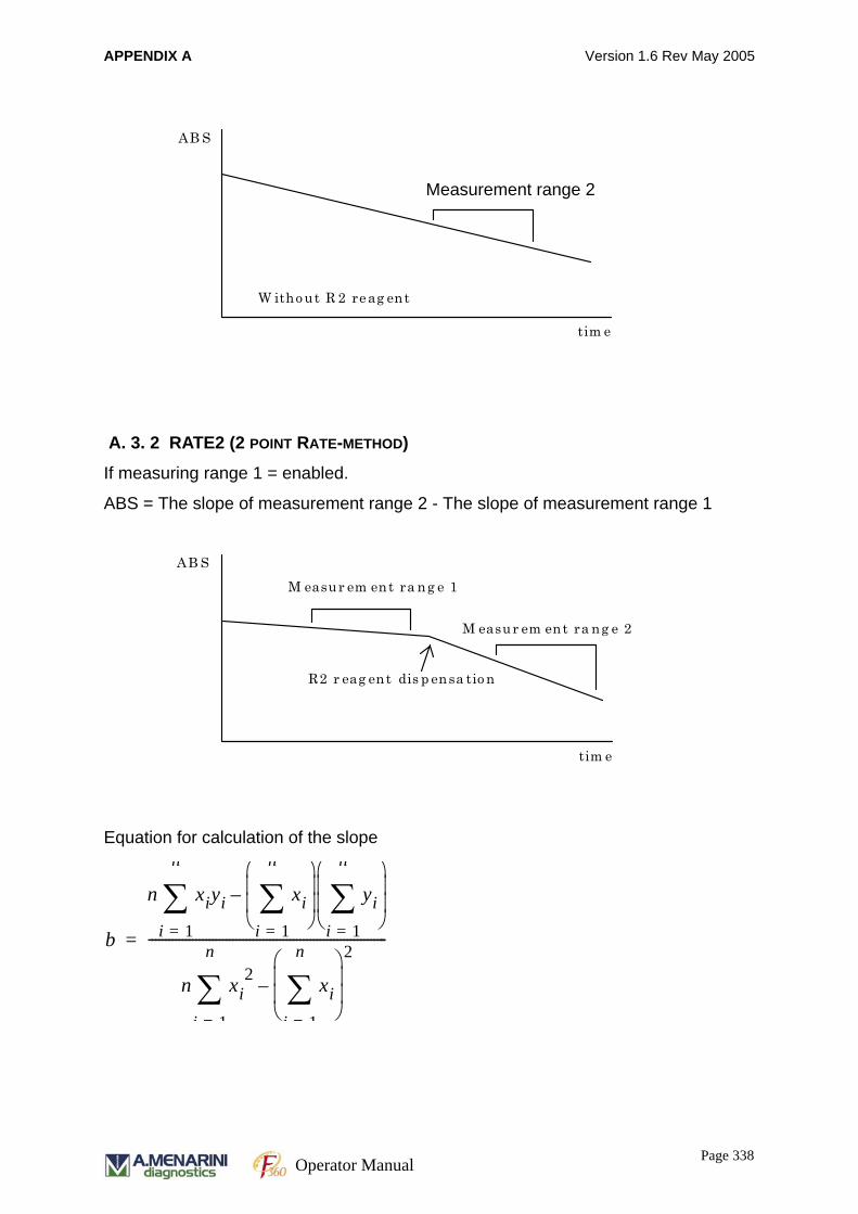
APPENDIX A Version 1.6 Rev May 2005
A. 3. 2 RATE2 (2 POINT RATE-METHOD)
If measuring range 1 = enabled.
ABS = The slope of measurement range 2 - The slope of measurement range 1
Equation for calculation of the slope
AB S
tim e
W itho ut R 2 re ag ent
M easur em ent ra ng e 2 Measurement range 2
AB S
tim e
M easur em ent ra ng e 2
M easur em ent ra ng e 1
R2 r eag ent dis p ensa tio n
b
n xiyi xii 1=
n
∑⎝ ⎠⎜ ⎟⎜ ⎟⎛ ⎞
yii 1=
n
∑⎝ ⎠⎜ ⎟⎜ ⎟⎛ ⎞
–
i 1=
n
∑
n xi2 xi
i 1=
n
∑⎝ ⎠⎜ ⎟⎜ ⎟⎛ ⎞ 2
–
i 1=
n
∑
-----------------------------------------------------------------------=
Page 338Operator Manual
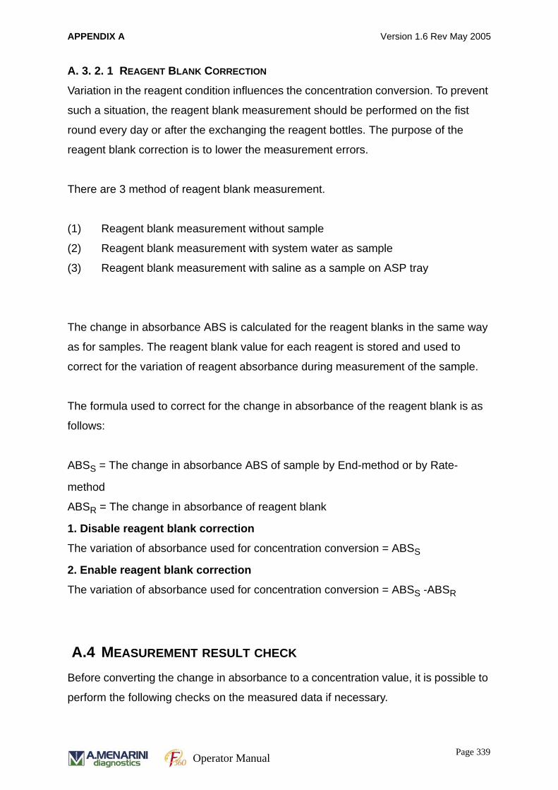
APPENDIX A Version 1.6 Rev May 2005
A. 3. 2. 1 REAGENT BLANK CORRECTION
Variation in the reagent condition influences the concentration conversion. To prevent
such a situation, the reagent blank measurement should be performed on the fist
round every day or after the exchanging the reagent bottles. The purpose of the
reagent blank correction is to lower the measurement errors.
There are 3 method of reagent blank measurement.
(1) Reagent blank measurement without sample
(2) Reagent blank measurement with system water as sample
(3) Reagent blank measurement with saline as a sample on ASP tray
The change in absorbance ABS is calculated for the reagent blanks in the same way
as for samples. The reagent blank value for each reagent is stored and used to
correct for the variation of reagent absorbance during measurement of the sample.
The formula used to correct for the change in absorbance of the reagent blank is as
follows:
ABSS = The change in absorbance ABS of sample by End-method or by Rate-
method
ABSR = The change in absorbance of reagent blank
1. Disable reagent blank correction
The variation of absorbance used for concentration conversion = ABSS
2. Enable reagent blank correction
The variation of absorbance used for concentration conversion = ABSS -ABSR
A.4 MEASUREMENT RESULT CHECK
Before converting the change in absorbance to a concentration value, it is possible to
perform the following checks on the measured data if necessary.
Page 339Operator Manual

APPENDIX A Version 1.6 Rev May 2005
Linearity Check
Absorbance Limit Check
Prozone Check
A. 4. 1 LINEARITY CHECK
The linearity of kinetic assays (RATE calculation) is calculated by measuring the
deviation of the reaction curve from the linear behaviour. If the specified value is
exceeded, the system gives a LIN flag indicating that the sample has failed the
linearity check, with the result.
The linearity value L is the difference in absorbance change between the first four and
the last four measured points (of the measuring range defined in chemistry
parameters) as a percentage of the total slope of the measuring range. If the linearity
ABS
time
dABS total
dABS last
dABS first
1. measuring point of the measuring range
n. measuring point of the measuring range
ABS
time
dABS last
dABS first
Change 4 measurement points by thecalculation using the moving average. Calculate slope by least squares method
Page 340Operator Manual
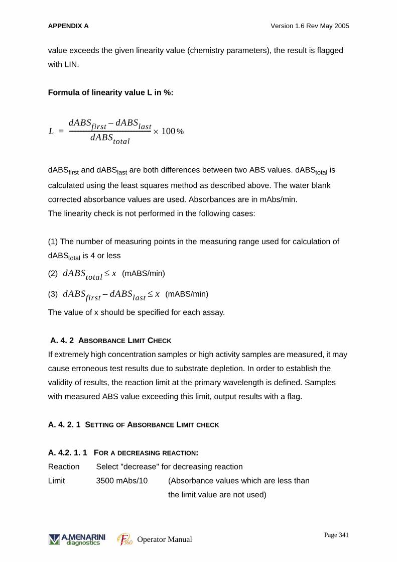
APPENDIX A Version 1.6 Rev May 2005
value exceeds the given linearity value (chemistry parameters), the result is flagged
with LIN.
Formula of linearity value L in %:
%
dABSfirst and dABSlast are both differences between two ABS values. dABStotal is
calculated using the least squares method as described above. The water blank
corrected absorbance values are used. Absorbances are in mAbs/min.
The linearity check is not performed in the following cases:
(1) The number of measuring points in the measuring range used for calculation of
dABStotal is 4 or less
(2) (mABS/min)
(3) (mABS/min)
The value of x should be specified for each assay.
A. 4. 2 ABSORBANCE LIMIT CHECK
If extremely high concentration samples or high activity samples are measured, it may
cause erroneous test results due to substrate depletion. In order to establish the
validity of results, the reaction limit at the primary wavelength is defined. Samples
with measured ABS value exceeding this limit, output results with a flag.
A. 4. 2. 1 SETTING OF ABSORBANCE LIMIT CHECK
A. 4.2. 1. 1 FOR A DECREASING REACTION:
Reaction Select "decrease" for decreasing reaction
Limit 3500 mAbs/10 (Absorbance values which are less than
the limit value are not used)
LdABSfirst dABSlast–
dABStotal----------------------------------------------------- 100×=
dABStotal x≤
dABSfirst dABSlast– x≤
Page 341Operator Manual
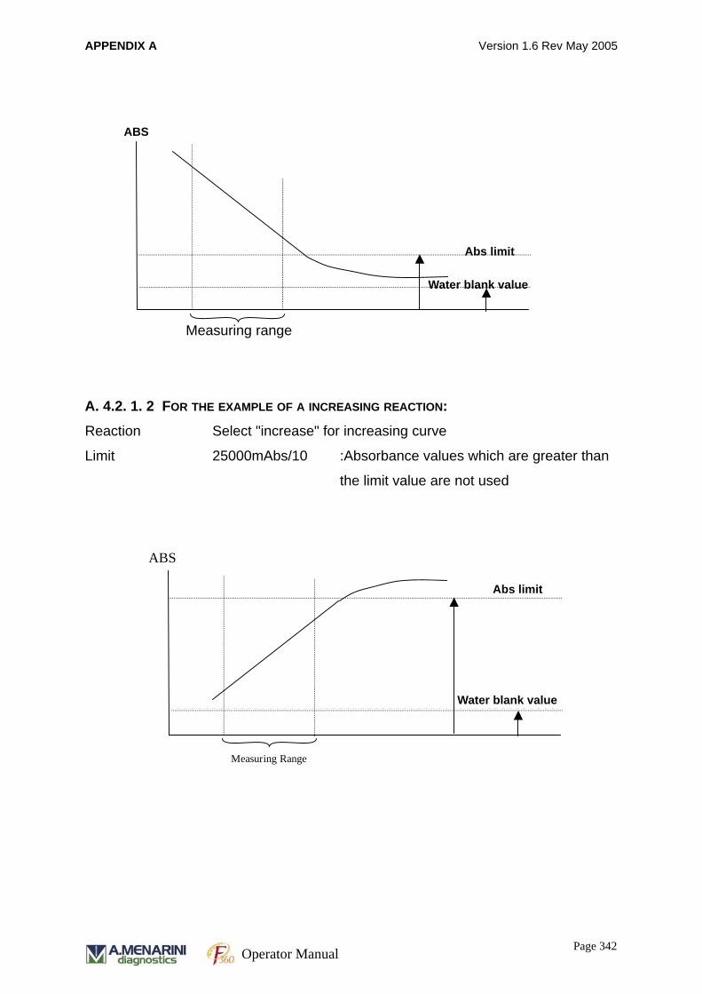
APPENDIX A Version 1.6 Rev May 2005
A. 4.2. 1. 2 FOR THE EXAMPLE OF A INCREASING REACTION:
Reaction Select "increase" for increasing curve
Limit 25000mAbs/10 :Absorbance values which are greater than
the limit value are not used
Measuring range
Abs limit
Water blank value
ABS
ABS
Measuring Range
Water blank value
Abs limit
Page 342Operator Manual
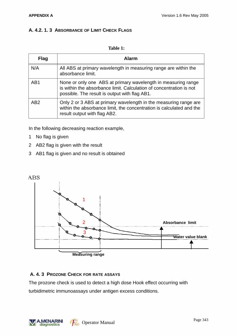
APPENDIX A Version 1.6 Rev May 2005
A. 4.2. 1. 3 ABSORBANCE OF LIMIT CHECK FLAGS
In the following decreasing reaction example,
1 No flag is given
2 AB2 flag is given with the result
3 AB1 flag is given and no result is obtained
A. 4. 3 PROZONE CHECK FOR RATE ASSAYS
The prozone check is used to detect a high dose Hook effect occurring with
turbidimetric immunoassays under antigen excess conditions.
Table 1:
Flag Alarm
N/A All ABS at primary wavelength in measuring range are within the absorbance limit.
AB1 None or only one ABS at primary wavelength in measuring range is within the absorbance limit. Calculation of concentration is not possible. The result is output with flag AB1.
AB2 Only 2 or 3 ABS at primary wavelength in the measuring range are within the absorbance limit, the concentration is calculated and the result output with flag AB2.
Absorbance limit
Water value blank
Measuring range
1
2
3
Page 343Operator Manual
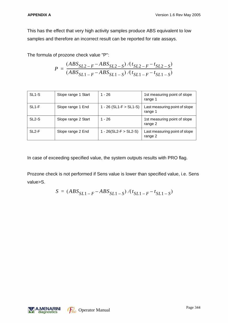
APPENDIX A Version 1.6 Rev May 2005
This has the effect that very high activity samples produce ABS equivalent to low
samples and therefore an incorrect result can be reported for rate assays.
The formula of prozone check value "P":
In case of exceeding specified value, the system outputs results with PRO flag.
Prozone check is not performed if Sens value is lower than specified value, i.e. Sens
value>S.
SL1-S Slope range 1 Start 1 - 26 1st measuring point of slope range 1
SL1-F Slope range 1 End 1 - 26 (SL1-F > SL1-S) Last measuring point of slope range 1
SL2-S Slope range 2 Start 1 - 26 1st measuring point of slope range 2
SL2-F Slope range 2 End 1 - 26(SL2-F > SL2-S) Last measuring point of slope range 2
PABSSL2 F– ABSSL2 S––( ) tSL2 F– tSL2 S––( )⁄
ABSSL1 F– ABSSL1 S––( ) tSL1 F– tSL1 S––( )⁄----------------------------------------------------------------------------------------------------------------------=
S ABSSL1 F– ABSSL1 S––( ) tSL1 F– tSL1 S––( )⁄=
Page 344Operator Manual

APPENDIX A Version 1.6 Rev May 2005
A. 4. 3. 1 PROZONE CHECK FOR END METHOD
Display menu
A. 4.3. 1. 1 PROZONE SETTING AT END METHOD
1. Input value in SL1 only
When *3 is ‘Upper’ case
Prozone limit error if actual measurement value > *2 setting value
When *3 is ‘Lower’ case
Prozone limit error if actual measurement value < *2 setting value
*1 *2 *3*4
*5
ABS
*2 Setting(Actual Measurement value)
Water blank value
*5 setting value
*4 SL1 range
}
Page 345Operator Manual
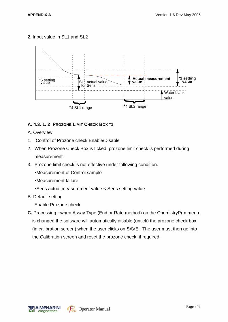
APPENDIX A Version 1.6 Rev May 2005
2. Input value in SL1 and SL2
A. 4.3. 1. 2 PROZONE LIMIT CHECK BOX *1
A. Overview
1. Control of Prozone check Enable/Disable
2. When Prozone Check Box is ticked, prozone limit check is performed during
measurement.
3. Prozone limit check is not effective under following condition.
•Measurement of Control sample
•Measurement failure
•Sens actual measurement value < Sens setting value
B. Default setting
Enable Prozone check
C. Processing - when Assay Type (End or Rate method) on the ChemistryPrm menu
is changed the software will automatically disable (untick) the prozone check box
(in calibration screen) when the user clicks on SAVE. The user must then go into
the Calibration screen and reset the prozone check, if required.
*2 setting Actual measurement value value
Water blankvalue
*5 setting value SL1 actual valuefor Sens.
*4 SL1 range *4 SL2 range
} }
Page 346Operator Manual
APPENDIX A Version 1.6 Rev May 2005
A. 4.3. 1. 3 PROZONE LIMIT CHECK BOX *2
A. Overview
1. Enter prozone limit value in 0.1mAbs unit (Ex: 50.0 = 5mAbs)
2. Boundary value is regarded as normal value.
Note: For end method, unit "mAbs" appears on the display since units for Rate
method are different.
B. Default setting
00
C. When Assay Type (End or Rate method) on the ChemistryPrm menu is changed
this parameter becomes ineffective.
A. 4.3. 1. 4 UPPER/LOWER SETTING *3
A. Overview
1. Judgment code (<, >) is used for prozone limit check error.
2. Boundary value is regarded as normal value.
B. Default setting
Upper
C. When Assay Type (End or Rate method) on the ChemistryPrm menu is changed
this parameter is ineffective.
A. 4.3. 1. 5 PROZONE LIMIT RANGE SETTING (*4)
A. Overview
1. Set up Prozone limit check range.
2. Enter measuring point (from 1 to 26).
3. SL1-S and SL1-F must be entered if prozone limit check is enabled.
4. If SL2-S and SL2-F are blank, prozone value is the difference between actual
measurement value and water blank value.
5. The following are checked when "Save" box is clicked.
a. If -S and -F are same at Rate method: Error
b. If -S and -F are same at End method: Normal
Page 347Operator Manual
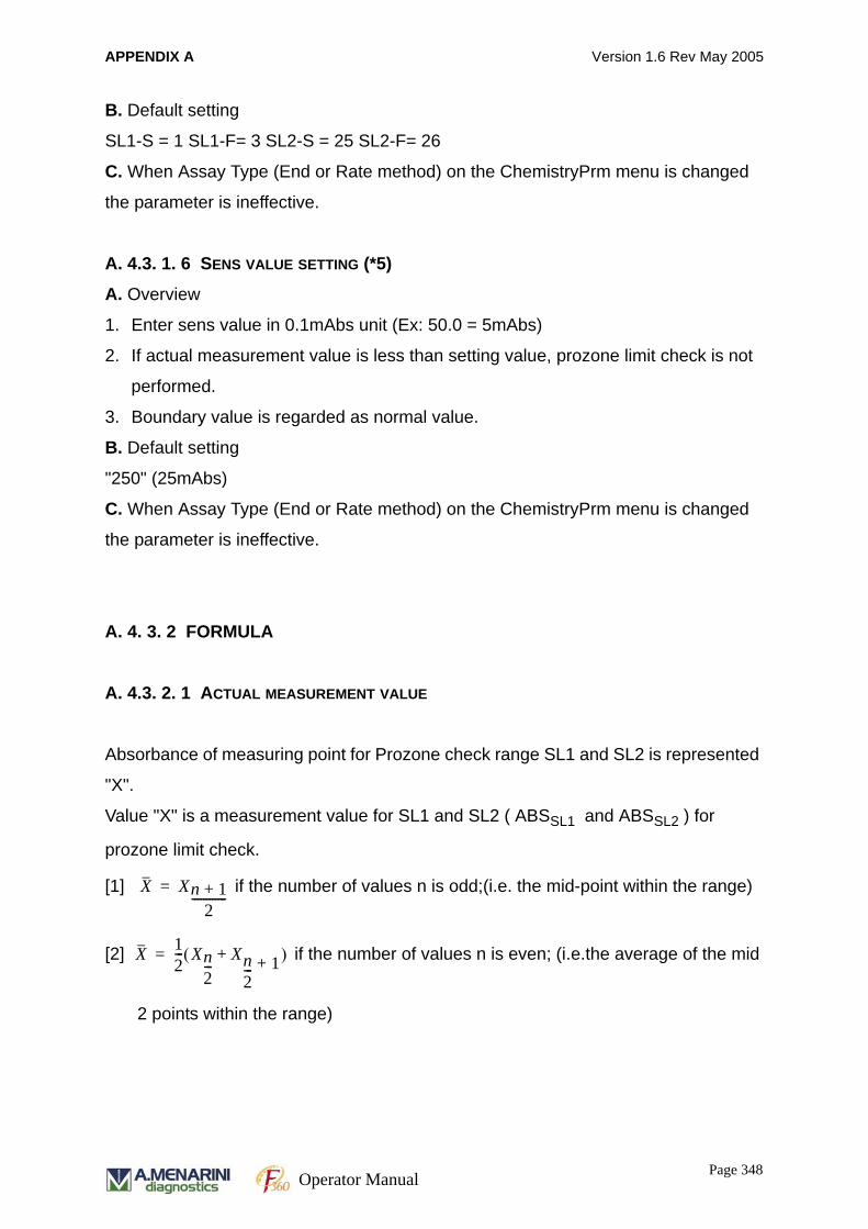
APPENDIX A Version 1.6 Rev May 2005
B. Default setting
SL1-S = 1 SL1-F= 3 SL2-S = 25 SL2-F= 26
C. When Assay Type (End or Rate method) on the ChemistryPrm menu is changed
the parameter is ineffective.
A. 4.3. 1. 6 SENS VALUE SETTING (*5)
A. Overview
1. Enter sens value in 0.1mAbs unit (Ex: 50.0 = 5mAbs)
2. If actual measurement value is less than setting value, prozone limit check is not
performed.
3. Boundary value is regarded as normal value.
B. Default setting
"250" (25mAbs)
C. When Assay Type (End or Rate method) on the ChemistryPrm menu is changed
the parameter is ineffective.
A. 4. 3. 2 FORMULA
A. 4.3. 2. 1 ACTUAL MEASUREMENT VALUE
Absorbance of measuring point for Prozone check range SL1 and SL2 is represented
"X".
Value "X" is a measurement value for SL1 and SL2 ( ABSSL1 and ABSSL2 ) for
prozone limit check.
[1] if the number of values n is odd;(i.e. the mid-point within the range)
[2] if the number of values n is even; (i.e.the average of the mid
2 points within the range)
X Xn 1+2
------------=
X 12--- Xn
2---
Xn2--- 1++( )=
Page 348Operator Manual
APPENDIX A Version 1.6 Rev May 2005
A. 4. 3. 3 PROZONE CHECK FORMULA
[1] Actual measurement value "P" is defined if the range SL1 and SL2 are defined.
P =ABSSL1-ABSSL2
[2] Actual measurement value "P" is defined if the range SL1 is defined.
P = ABSSL1 - ABSwaterblank ( ABSreagent blank is not subtracted)
If ‘Upper’ is selected
Error if "P > Prozone value" (Prozone value is defined on the display menu)
If ‘Lower’ is selected
Error if "P < Prozone value" (Prozone value is defined on the display menu)
A. 4. 3. 4 SENS CHECK FORMULA
Actual measurement value "S" for Sens is defined by the following formula whether
SL1 and SL2 ranges are defined or if SL1 range only is defined.
S = ABSSL1 - ABSwaterblank ( ABSreagent blank is not subtracted)
When "S < Sens value", Prozone Limit Check is not performed.
(Sens value is defined on the display menu)
A.5 CALIBRATION
A. 5. 1 MEASUREMENT PRINCIPLES OF CALIBRATION
By measuring a set of calibrators with known concentration and calculating the ΔABS
values, a calibration function can bw defined:
ABScalibratorΔ f concentrationcalibrator( )=
Page 349Operator Manual
APPENDIX A Version 1.6 Rev May 2005
The unknown concentration of a sample can be determined from measured/
calculated ΔABS values by using the inverse formula of the calibration function.
A. 5. 2 CALIBRATION CHECK
Standards/Calibrators are measured in duplicate or triplicate for each. The following
checks are carried out if the functions are enabled on the calibration checks menu.
A. 5. 2. 1 DUPLICATE LIMIT (ALLOWABLE VARIATION LIMIT)
The system judges if the difference between absorbance values obtained from the
duplicate measurement are within the specified variation limit or not. In the case of
the specified range being exceeded, the system judges calibration error and the last
calibration value is effective. The value is entered in absorbance mABS/10 in the
software.
A. 5. 2. 2 SENSITIVITY (ALLOWABLE SENSITIVITY LIMIT)
If the difference in absorbance ΔABS between the first and last calibrators after full
calibration is smaller than specified value on the menu, the system judges calibration
error and the last calibration value is effective.
concentrationsample finverse ABSsampleΔ( )=
Page 350Operator Manual
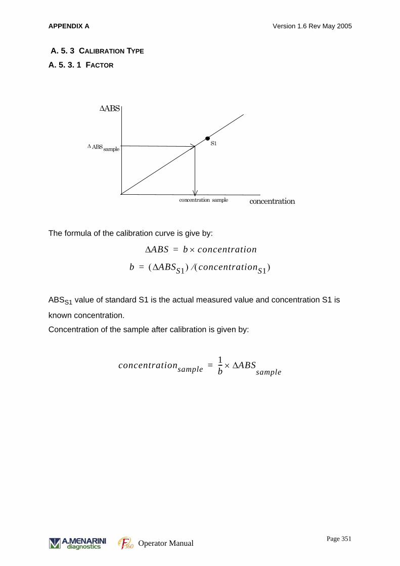
APPENDIX A Version 1.6 Rev May 2005
A. 5. 3 CALIBRATION TYPE
A. 5. 3. 1 FACTOR
The formula of the calibration curve is give by:
ABSS1 value of standard S1 is the actual measured value and concentration S1 is
known concentration.
Concentration of the sample after calibration is given by:
ABS Δ
ABS Δ sample
concentration sample
S1
concentration
ABSΔ b concentration×=
b ABSS1Δ( ) concentrationS1( )⁄=
concentrationsample1b--- ABSΔ×
sample=
Page 351Operator Manual

APPENDIX A Version 1.6 Rev May 2005
A. 5. 3. 2 LINEAR
The formula of the calibration curve is given by:
where intercept "a " and slope " b" are calculated according to the least squares
method with:
ABS Δ
concentration
ABS Δ sample
concentration sample
Sn
S1
S2
ABSΔ a b concentration×+=
a
yi b xii 1=
n
∑–
i 1=
n
∑n
---------------------------------------=
b
n xiyi xii 1=
n
∑⎝ ⎠⎜ ⎟⎜ ⎟⎛ ⎞
yii 1=
n
∑⎝ ⎠⎜ ⎟⎜ ⎟⎛ ⎞
–
i 1=
n
∑
n xi2 xi
i 1=
n
∑⎝ ⎠⎜ ⎟⎜ ⎟⎛ ⎞ 2
–
i 1=
n
∑
-----------------------------------------------------------------------=
Page 352Operator Manual
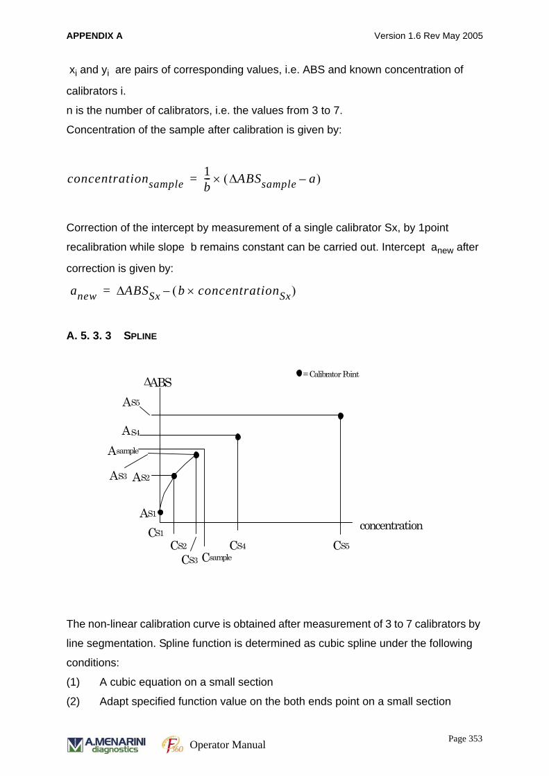
APPENDIX A Version 1.6 Rev May 2005
xi and yi are pairs of corresponding values, i.e. ABS and known concentration of
calibrators i.
n is the number of calibrators, i.e. the values from 3 to 7.
Concentration of the sample after calibration is given by:
Correction of the intercept by measurement of a single calibrator Sx, by 1point
recalibration while slope b remains constant can be carried out. Intercept anew after
correction is given by:
A. 5. 3. 3 SPLINE
The non-linear calibration curve is obtained after measurement of 3 to 7 calibrators by
line segmentation. Spline function is determined as cubic spline under the following
conditions:
(1) A cubic equation on a small section
(2) Adapt specified function value on the both ends point on a small section
concentrationsample1b--- ABSsampleΔ a–( )×=
anew ABSSxΔ b concentrationSx×( )–=
ABS Δ
A sample
sample
S2
S4
S3
S1
S5 C
A
A C S1
= Calibrator Point
C C S2
A
A
S3
A
C S4 C
S5
concentration
Page 353Operator Manual

APPENDIX A Version 1.6 Rev May 2005
(3) Lead derivatives to the second floor on the boundary of small section
continuously.
The formula of calibration curve on each small section is given by:
The procedure to convert the measured ABS to concentration is as follows:
(1) Find the section that the measured ABS fits into
(2) Substitute the ABS into the cubic equation for that section, and convert to the
concentration by Cardano's formula or by Newton-Raphson method
A. 5. 3. 4 POINT TO POINT
Each calibrator is connected to the next one by a straight line. For example, if there
are 5 standards, the calibration curve is composed of four straight lines k=1 to 4.
The formula for the point to point calibration curve is given by:
ABSΔ A∗concentration3 B∗concentration2 C∗concentration D+ + +=
ABS Δ
A sample
sample
S2
S4
S3
S1
S5 C
A
A C S1
= Calibrator Point
C C S2
A
A
S3
A
C S4 C
S5
concentration
ABSΔ a b∗concentration+=
Page 354Operator Manual
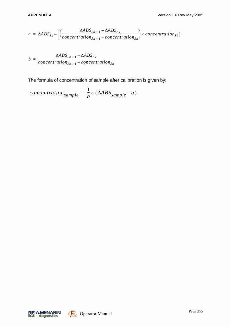
APPENDIX A Version 1.6 Rev May 2005
The formula of concentration of sample after calibration is given by:
a ABSSkΔABSSk 1+Δ ABSSkΔ–
concentrationSk 1+ concentrationSk–-------------------------------------------------------------------------------------------------⎠
⎞ concentrationSk ]×⎝⎛–=
bABSSk 1+Δ ABSSkΔ–
concentrationSk 1+ concentrationSk–-------------------------------------------------------------------------------------------------=
concentrationsample1b--- ABSsampleΔ a )–(×=
Page 355Operator Manual

APPENDIX A Version 1.6 Rev May 2005
Page 356Operator Manual
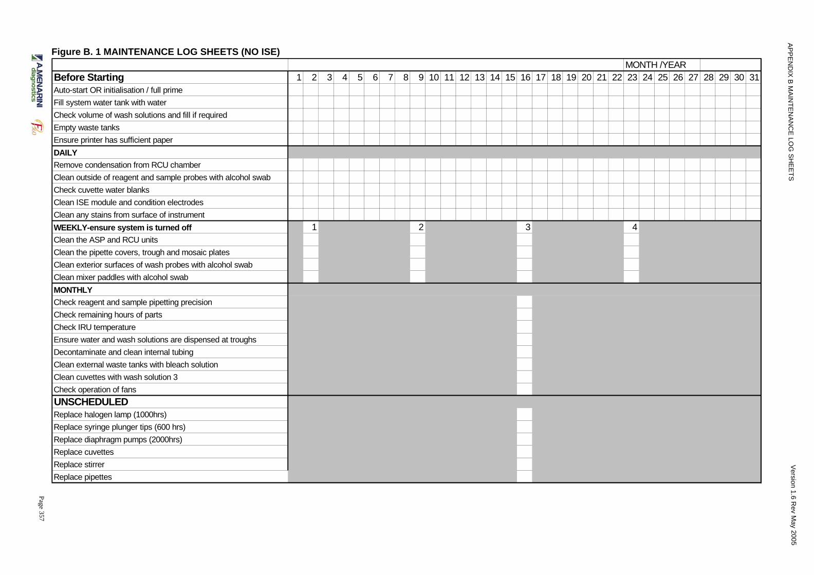
Page 357
AP
PE
ND
IX B
MA
INT E
NA
NC
E L O
G S
HE
ETS
Ve rs io n 1 .6 R
ev Ma y 2
Figure B. 1 MAINTENANCE LOG SHEETS (NO ISE)MONTH /YEAR
Before Starting 1 2 3 4 5 6 7 8 9 10 11 12 13 14 15 16 17 18 19 20 21 22 23 24 25 26 27 28 29 30 31Auto-start OR initialisation / full primeFill system water tank with waterCheck volume of wash solutions and fill if requiredEmpty waste tanksEnsure printer has sufficient paperDAILYRemove condensation from RCU chamberClean outside of reagent and sample probes with alcohol swabCheck cuvette water blanksClean ISE module and condition electrodesClean any stains from surface of instrumentWEEKLY-ensure system is turned off 1 2 3 4Clean the ASP and RCU unitsClean the pipette covers, trough and mosaic platesClean exterior surfaces of wash probes with alcohol swabClean mixer paddles with alcohol swabMONTHLYCheck reagent and sample pipetting precisionCheck remaining hours of partsCheck IRU temperatureEnsure water and wash solutions are dispensed at troughsDecontaminate and clean internal tubingClean external waste tanks with bleach solution Clean cuvettes with wash solution 3Check operation of fansUNSCHEDULEDReplace halogen lamp (1000hrs)Replace syringe plunger tips (600 hrs)Replace diaphragm pumps (2000hrs)Replace cuvettesReplace stirrerReplace pipettes
00 5

Page 358
AP
PE
ND
IX B
MA
INT E
NA
NC
E L O
G S
HE
ETS
Ve rs io n 1 .6 R
ev Ma y 2
Figure B. 2 MAINTENANCE LOG SHEETS (with ISE)MONTH /YEAR
Before Starting 1 2 3 4 5 6 7 8 9 10 11 12 13 14 15 16 17 18 19 20 21 22 23 24 25 26 27 28 29 30 31Auto-start OR initialisation / full primeFill system water tank with waterCheck volume of wash solutions and fill if requiredEmpty waste tanksEnsure printer has sufficient paperDAILYRemove condensation from RCU chamberClean outside of reagent and sample probes with alcohol swabCheck cuvette water blanksClean any stains from surface of instrumentClean ISE module and condition electrodesWEEKLY-ensure system is turned off 1 2 3 4Clean the ASP and RCU unitsClean the pipette covers, trough and mosaic platesClean exterior surfaces of wash probes with alcohol swabClean mixer paddles with alcohol swabMONTHLYCheck reagent and sample pipetting precisionCheck remaining hours of partsCheck IRU temperatureEnsure water and wash solutions are dispensed at troughsDecontaminate and clean internal tubingClean external waste tanks with bleach solution Clean cuvettes with wash solution 3Check operation of fansUNSCHEDULEDReplace halogen lamp (1000hrs)Replace syringe plunger tips (600 hrs)Replace diaphragm pumps (2000hrs)Replace cuvettesReplace stirrerReplace pipettes
00 5
APPENDIX C SOFTWARE UPGRADE PROCEDURE Version 1.6 Rev May 2005
APPENDIX C.
SOFTWARE UPGRADE PROCEDUREPC software upgrading procedure for the Clinical Chemistry Analyzer unit is
explained here. The following instructions assume that an Auto-Run CD is available
for user interface software and PC software version is PC114 or greater. Software
supplied on a different CD may differ significantly from this procedure. Please consult
the literature accompanying the CD.
C.1 BACKUP OF SYSTEM PARAMETERS
As for the backup procedure, refer to "Operator's Manual" (4. 4. 7“Data Backup” on
page 170).
(1)Start the analyzer system.
(2) Click on [System Parameters] of the job menu.
(3) Click on [Backup (F10)] of the function menu.
(4) Insert the floppy disk into the drive.
If the inserted floppy disk is unformatted, click on the Format button of "Format FD".
(5) Click on the Save button of "Save mechanical Values to FD".
(6) Click on the Save button of "Save user parameters to FD".
(7) Click on the Save button of "Save Data" at the data backup block.
C.2 TERMINATE ALL PROGRAMS ON THE PC.For the User-interface Program, terminate it as follows:
(1) While holding down the [Ctrl] key, press the [.](period) key. Soon the following
buttons are displayed:
"Sleep"
"Power Off"
"Cancel"
(2) Click on the [Power Off] button, and wait until the Windows desktop reappears.
Page 359Operator Manual

APPENDIX C SOFTWARE UPGRADE PROCEDURE Version 1.6 Rev May 2005
C.3 USER-INTERFACE SOFTWARE UPGRADE (ON WINDOWS XP) C. 3.1 REMOVAL OF OLD USER-INTERFACE PROGRAM
(1)On the Windows desktop, start "ADD/REMOVE PROGRAMS" as follows:
• Click on the [Start] button.
• Select "Setting".
• Click on "Control Panel".
• Double-click on "Add/Remove Programs", and soon its window opens.
(2) Click on "Analyzer" on the selection box, then click on the [Add/Remove]
button. In a while the installer/uninstaller "InstallShield Wizard" starts up.
(3) Click on the [Next>] button, and the "Program Maintenance" screen appears.
(4) Select the "Remove" radio button, then click on the [Next>] button. Soon, the
"Remove the Program" screen appears.
(5) Click on the [Remove] button. After a bar graph is displayed, "InstallShield
Wizard Completed" is displayed.
(6) Click on the [Finish] button, and the Windows desktop reappears.
(7) Proceed to B (1) below.
C. 3.2 INSTALLATION OF NEW USER-INTERFACE PROGRAM
(1) Insert the New Software CD into the drive, and soon the following message
reads automatically:
"Welcome to the InstallShield Wizard …"
(2) Click on the [Next>] button, and the "Customer Information" screen appears.
(3) Fill out the blanks as follows:
User Name: Analyzer
Organization: FEC
NOTE:Type "Analyzer" and "FEC" as shown above. Do not change the case of
letters.
(4) Click on the [Next>] button, and "Destination Folder" appears.
(5) Click on the [Next>] button, and "Ready to Install the Program" appears.
(6) Click on the [Install] button, and a bar graph is displayed. Wait until
"InstallShield Wizard Completed" appears.
Page 360Operator Manual
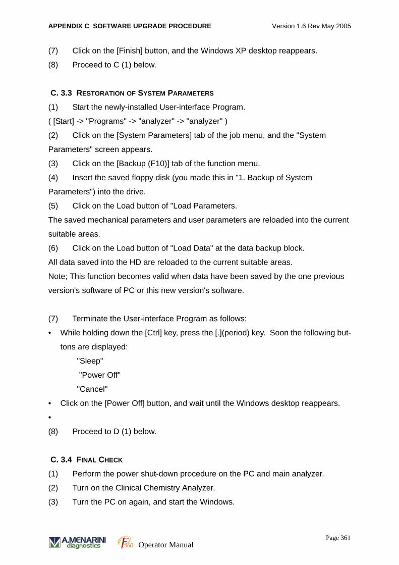
APPENDIX C SOFTWARE UPGRADE PROCEDURE Version 1.6 Rev May 2005
(7) Click on the [Finish] button, and the Windows XP desktop reappears.
(8) Proceed to C (1) below.
C. 3.3 RESTORATION OF SYSTEM PARAMETERS
(1) Start the newly-installed User-interface Program.
( [Start] -> "Programs" -> "analyzer" -> "analyzer" )
(2) Click on the [System Parameters] tab of the job menu, and the "System
Parameters" screen appears.
(3) Click on the [Backup (F10)] tab of the function menu.
(4) Insert the saved floppy disk (you made this in "1. Backup of System
Parameters") into the drive.
(5) Click on the Load button of "Load Parameters.
The saved mechanical parameters and user parameters are reloaded into the current
suitable areas.
(6) Click on the Load button of "Load Data" at the data backup block.
All data saved into the HD are reloaded to the current suitable areas.
Note; This function becomes valid when data have been saved by the one previous
version's software of PC or this new version's software.
(7) Terminate the User-interface Program as follows:
• While holding down the [Ctrl] key, press the [.](period) key. Soon the following but-
tons are displayed:
"Sleep"
"Power Off"
"Cancel"
• Click on the [Power Off] button, and wait until the Windows desktop reappears.
•
(8) Proceed to D (1) below.
C. 3.4 FINAL CHECK
(1) Perform the power shut-down procedure on the PC and main analyzer.
(2) Turn on the Clinical Chemistry Analyzer.
(3) Turn the PC on again, and start the Windows.
Page 361Operator Manual
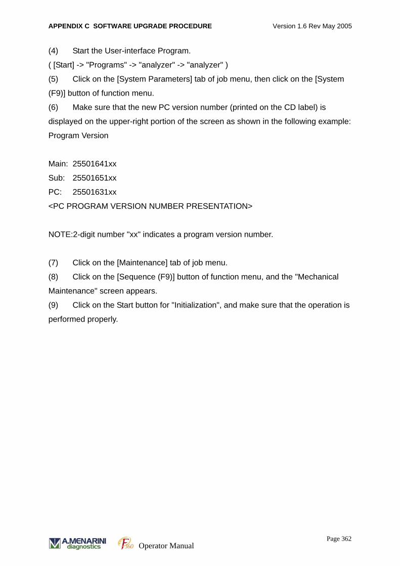
APPENDIX C SOFTWARE UPGRADE PROCEDURE Version 1.6 Rev May 2005
(4) Start the User-interface Program.
( [Start] -> "Programs" -> "analyzer" -> "analyzer" )
(5) Click on the [System Parameters] tab of job menu, then click on the [System
(F9)] button of function menu.
(6) Make sure that the new PC version number (printed on the CD label) is
displayed on the upper-right portion of the screen as shown in the following example:
Program Version
Main: 25501641xx
Sub: 25501651xx
PC: 25501631xx
<PC PROGRAM VERSION NUMBER PRESENTATION>
NOTE:2-digit number "xx" indicates a program version number.
(7) Click on the [Maintenance] tab of job menu.
(8) Click on the [Sequence (F9)] button of function menu, and the "Mechanical
Maintenance" screen appears.
(9) Click on the Start button for "Initialization", and make sure that the operation is
performed properly.
Page 362Operator Manual

APPENDIX C SOFTWARE UPGRADE PROCEDURE Version 1.6 Rev May 2005
Page 363Operator Manual

APPENDIX C SOFTWARE UPGRADE PROCEDURE Version 1.6 Rev May 2005
Page 364Operator Manual
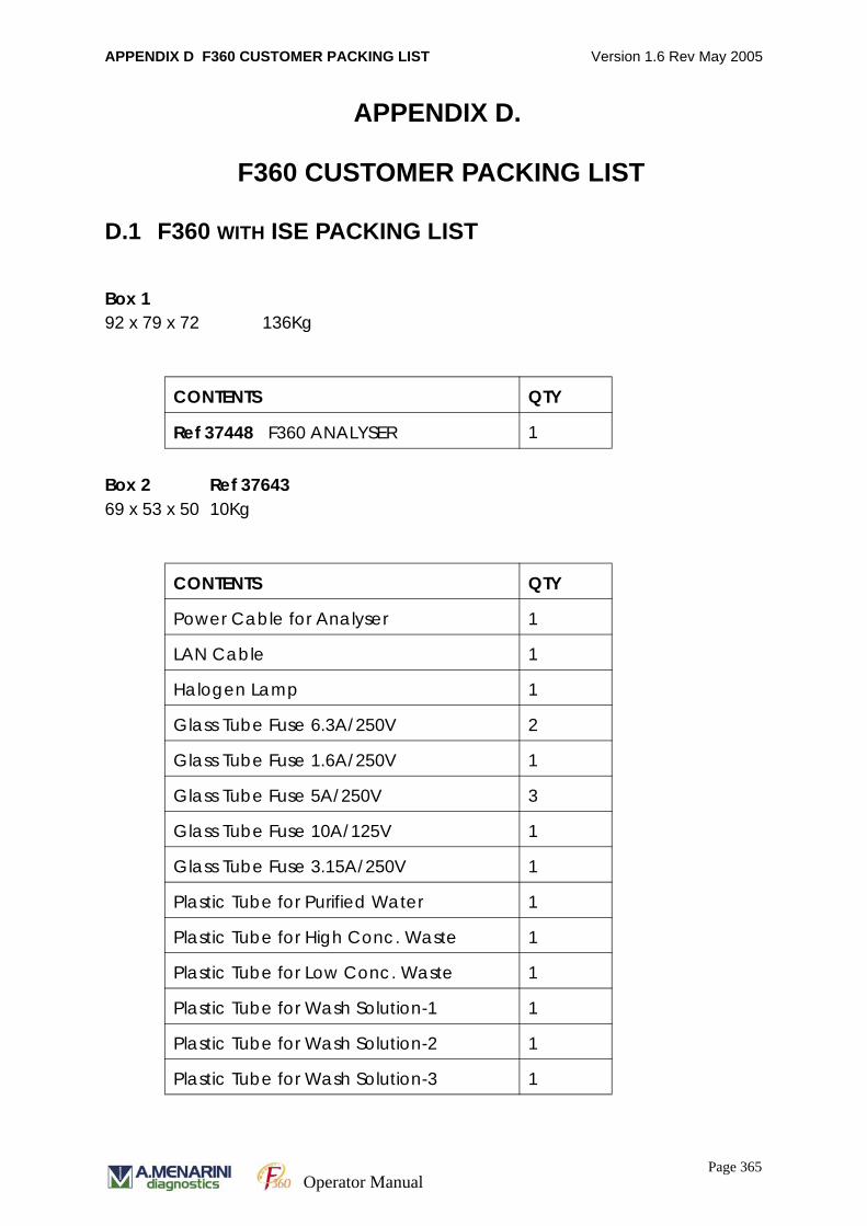
APPENDIX D F360 CUSTOMER PACKING LIST Version 1.6 Rev May 2005
APPENDIX D.
F360 CUSTOMER PACKING LIST
D.1 F360 WITH ISE PACKING LIST
Box 192 x 79 x 72 136Kg
Box 2 Ref 3764369 x 53 x 50 10Kg
CONTENTS QTY
Ref 37448 F360 ANALYSER 1
CONTENTS QTY
Power Cable for Analyser 1
LAN Cable 1
Halogen Lamp 1
Glass Tube Fuse 6.3A/250V 2
Glass Tube Fuse 1.6A/250V 1
Glass Tube Fuse 5A/250V 3
Glass Tube Fuse 10A/125V 1
Glass Tube Fuse 3.15A/250V 1
Plastic Tube for Purified Water 1
Plastic Tube for High Conc. Waste 1
Plastic Tube for Low Conc. Waste 1
Plastic Tube for Wash Solution-1 1
Plastic Tube for Wash Solution-2 1
Plastic Tube for Wash Solution-3 1
Page 365Operator Manual
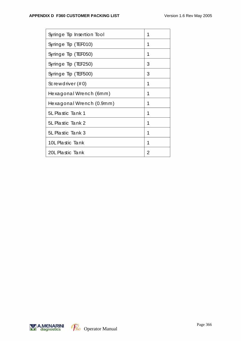
APPENDIX D F360 CUSTOMER PACKING LIST Version 1.6 Rev May 2005
Syringe Tip Insertion Tool 1
Syringe Tip (TEF010) 1
Syringe Tip (TEF050) 1
Syringe Tip (TEF250) 3
Syringe Tip (TEF500) 3
Screwdriver (#0) 1
Hexagonal Wrench (6mm) 1
Hexagonal Wrench (0.9mm) 1
5L Plastic Tank 1 1
5L Plastic Tank 2 1
5L Plastic Tank 3 1
10L Plastic Tank 1
20L Plastic Tank 2
Page 366Operator Manual

APPENDIX D F360 CUSTOMER PACKING LIST Version 1.6 Rev May 2005
Box 3 Ref 3764465 x 36 x 30 5Kg
Box 4 39 x 39 x 17 5Kg
Box 555 x 50 x 30 14Kg
Box 6 Ref 3765830 x 30 x 20 4Kg
CONTENTS QTY
Sample Tray Asm 1
ASP Lid 1
Reagent Bottle Tray Asm 1
RCU Lid 1
CONTENTS QTY
Ref 37645 F360 Flat Screen 1
CONTENTS QTY
Ref 37542 F360 PC 1
CONTENTS QTY
37544 FGENT Wash Solution No 1 (Acid) 1 x 25ml
37545 FGENT Wash Solution No 2 (Alkali) 1 x 25ml
37546 FGENT Wash Solution No 3 (Neutral) 1 x 25ml
D200-0052 Probe Adjustment Tool 1
D200-0219 Pipette Cleaning Probe 1
Page 367Operator Manual
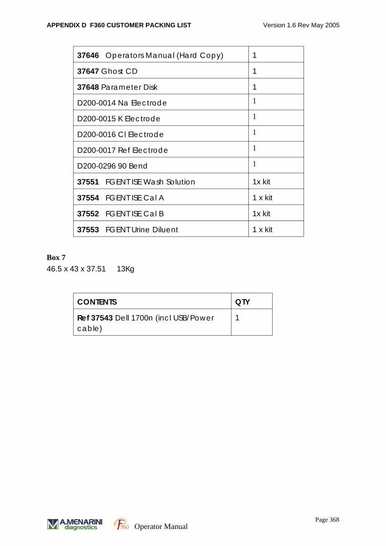
APPENDIX D F360 CUSTOMER PACKING LIST Version 1.6 Rev May 2005
Box 7 46.5 x 43 x 37.51 13Kg
37646 Operators Manual (Hard Copy) 1
37647 Ghost CD 1
37648 Parameter Disk 1
D200-0014 Na Electrode 1
D200-0015 K Electrode 1
D200-0016 Cl Electrode 1
D200-0017 Ref Electrode 1
D200-0296 90 Bend 1
37551 FGENT ISE Wash Solution 1x kit
37554 FGENT ISE Cal A 1 x kit
37552 FGENT ISE Cal B 1x kit
37553 FGENT Urine Diluent 1 x kit
CONTENTS QTY
Ref 37543 Dell 1700n (incl USB/Power cable)
1
Page 368Operator Manual
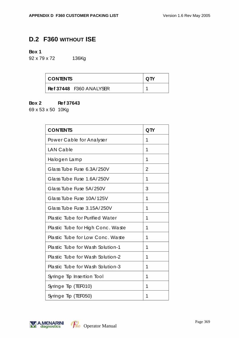
APPENDIX D F360 CUSTOMER PACKING LIST Version 1.6 Rev May 2005
D.2 F360 WITHOUT ISE
Box 192 x 79 x 72 136Kg
Box 2 Ref 37643 69 x 53 x 50 10Kg
CONTENTS QTY
Ref 37448 F360 ANALYSER 1
CONTENTS QTY
Power Cable for Analyser 1
LAN Cable 1
Halogen Lamp 1
Glass Tube Fuse 6.3A/250V 2
Glass Tube Fuse 1.6A/250V 1
Glass Tube Fuse 5A/250V 3
Glass Tube Fuse 10A/125V 1
Glass Tube Fuse 3.15A/250V 1
Plastic Tube for Purified Water 1
Plastic Tube for High Conc. Waste 1
Plastic Tube for Low Conc. Waste 1
Plastic Tube for Wash Solution-1 1
Plastic Tube for Wash Solution-2 1
Plastic Tube for Wash Solution-3 1
Syringe Tip Insertion Tool 1
Syringe Tip (TEF010) 1
Syringe Tip (TEF050) 1
Page 369Operator Manual
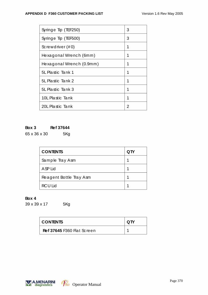
APPENDIX D F360 CUSTOMER PACKING LIST Version 1.6 Rev May 2005
Box 3 Ref 3764465 x 36 x 30 5Kg
Box 4 39 x 39 x 17 5Kg
Syringe Tip (TEF250) 3
Syringe Tip (TEF500) 3
Screwdriver (#0) 1
Hexagonal Wrench (6mm) 1
Hexagonal Wrench (0.9mm) 1
5L Plastic Tank 1 1
5L Plastic Tank 2 1
5L Plastic Tank 3 1
10L Plastic Tank 1
20L Plastic Tank 2
CONTENTS QTY
Sample Tray Asm 1
ASP Lid 1
Reagent Bottle Tray Asm 1
RCU Lid 1
CONTENTS QTY
Ref 37645 F360 Flat Screen 1
Page 370Operator Manual

APPENDIX D F360 CUSTOMER PACKING LIST Version 1.6 Rev May 2005
Box 555 x 50 x 30 14Kg
Box 6 Ref 3765830 x 30 x 20 2Kg
Box 7 46.5 x 43 x 37.51 13Kg
CONTENTS QTY
Ref 37542 F360 PC 1
CONTENTS QTY
37544 FGENT Wash Solution No 1 (Acid) 1
37545 FGENT Wash Solution No 2 (Alkali) 1
37546 FGENT Wash Solution No 3 (Neutral) 1
D200-0052 Probe Adjustment Tool 1
D200-0219 Pipette Cleaning Probe 1
37646 Operator Manual (Hard Copy) 1
37647 Ghost CD 1
37648 Parameter Disk 1
D200-0296 90 Bend 1
CONTENTS QTY
Ref 37543 Dell 1700n (incl USB/Power cable)
1
Page 371Operator Manual

APPENDIX D F360 CUSTOMER PACKING LIST Version 1.6 Rev May 2005
Page 372Operator Manual
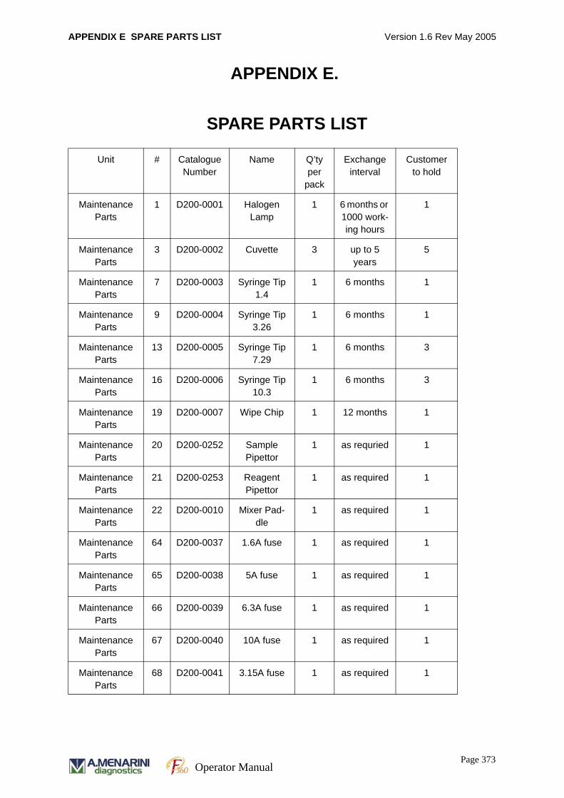
APPENDIX E SPARE PARTS LIST Version 1.6 Rev May 2005
APPENDIX E.
SPARE PARTS LIST
Unit # Catalogue Number
Name Q’ty per
pack
Exchange interval
Customer to hold
Maintenance Parts
1 D200-0001 Halogen Lamp
1 6 months or 1000 work-ing hours
1
Maintenance Parts
3 D200-0002 Cuvette 3 up to 5 years
5
Maintenance Parts
7 D200-0003 Syringe Tip 1.4
1 6 months 1
Maintenance Parts
9 D200-0004 Syringe Tip 3.26
1 6 months 1
Maintenance Parts
13 D200-0005 Syringe Tip 7.29
1 6 months 3
Maintenance Parts
16 D200-0006 Syringe Tip 10.3
1 6 months 3
Maintenance Parts
19 D200-0007 Wipe Chip 1 12 months 1
Maintenance Parts
20 D200-0252 Sample Pipettor
1 as requried 1
Maintenance Parts
21 D200-0253 Reagent Pipettor
1 as required 1
Maintenance Parts
22 D200-0010 Mixer Pad-dle
1 as required 1
Maintenance Parts
64 D200-0037 1.6A fuse 1 as required 1
Maintenance Parts
65 D200-0038 5A fuse 1 as required 1
Maintenance Parts
66 D200-0039 6.3A fuse 1 as required 1
Maintenance Parts
67 D200-0040 10A fuse 1 as required 1
Maintenance Parts
68 D200-0041 3.15A fuse 1 as required 1
Page 373Operator Manual
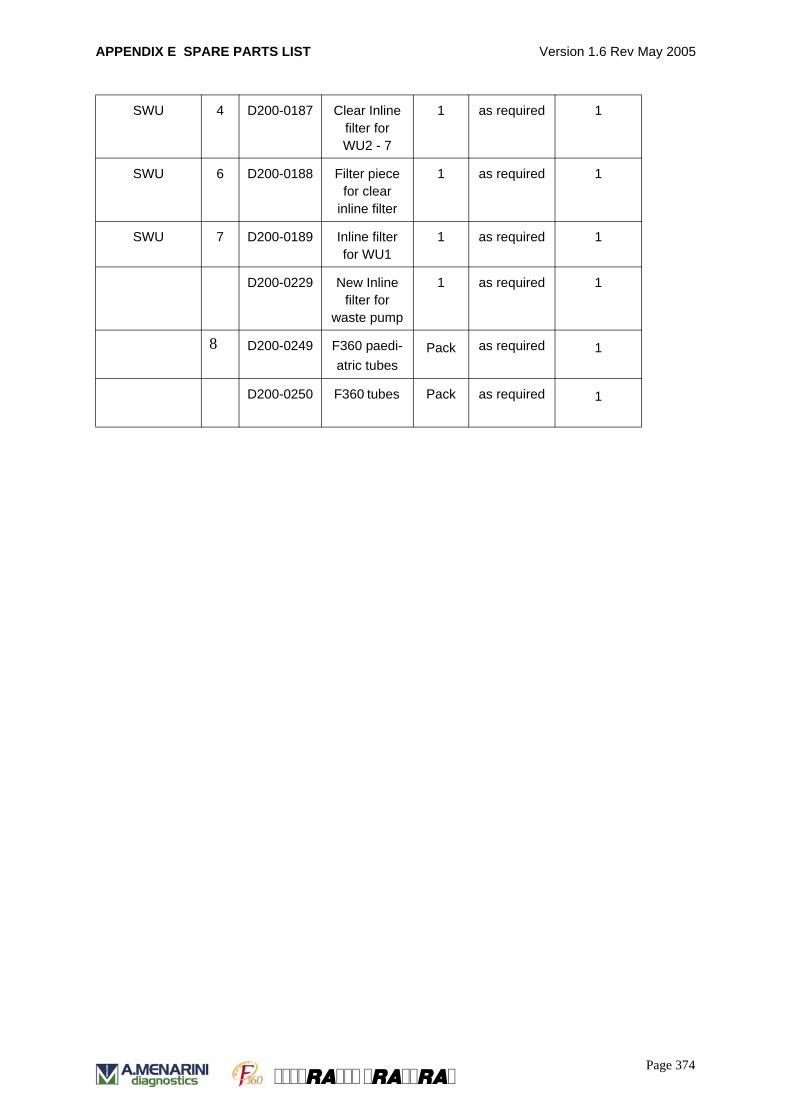
APPENDIX E SPARE PARTS LIST Version 1.6 Rev May 2005
SWU 4 D200-0187 Clear Inline filter for WU2 - 7
1 as required 1
SWU 6 D200-0188 Filter piece for clear
inline filter
1 as required 1
SWU 7 D200-0189 Inline filter for WU1
1 as required 1
D200-0229 New Inline filter for
waste pump
1 as required
1
8 D200-0249 F360 paedi-atric tubes
Pack as required 1
D200-0250 F360 tubes Pack as required 1
Page 374a a a
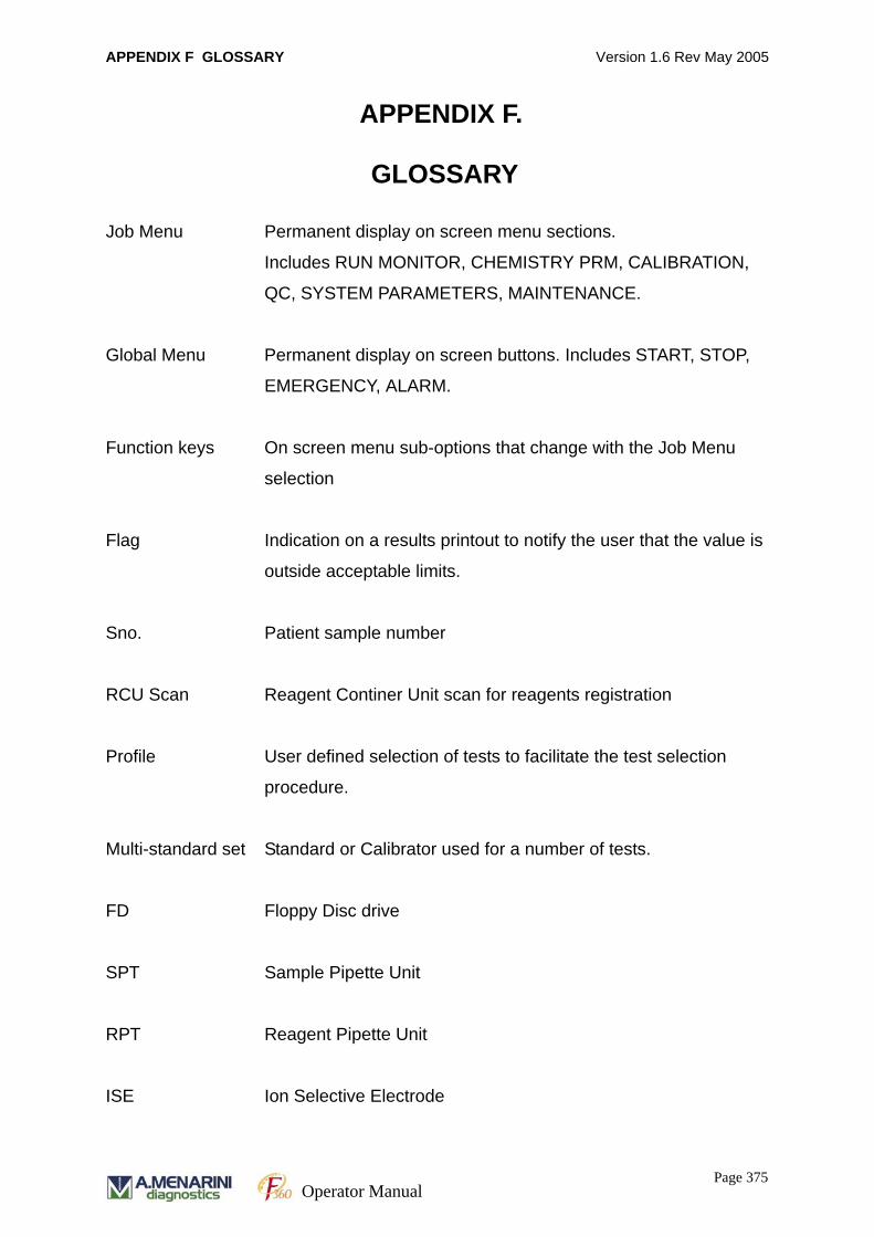
APPENDIX F GLOSSARY Version 1.6 Rev May 2005
APPENDIX F.
GLOSSARY
Job Menu Permanent display on screen menu sections.
Includes RUN MONITOR, CHEMISTRY PRM, CALIBRATION,
QC, SYSTEM PARAMETERS, MAINTENANCE.
Global Menu Permanent display on screen buttons. Includes START, STOP,
EMERGENCY, ALARM.
Function keys On screen menu sub-options that change with the Job Menu
selection
Flag Indication on a results printout to notify the user that the value is
outside acceptable limits.
Sno. Patient sample number
RCU Scan Reagent Continer Unit scan for reagents registration
Profile User defined selection of tests to facilitate the test selection
procedure.
Multi-standard set Standard or Calibrator used for a number of tests.
FD Floppy Disc drive
SPT Sample Pipette Unit
RPT Reagent Pipette Unit
ISE Ion Selective Electrode
Page 375Operator Manual
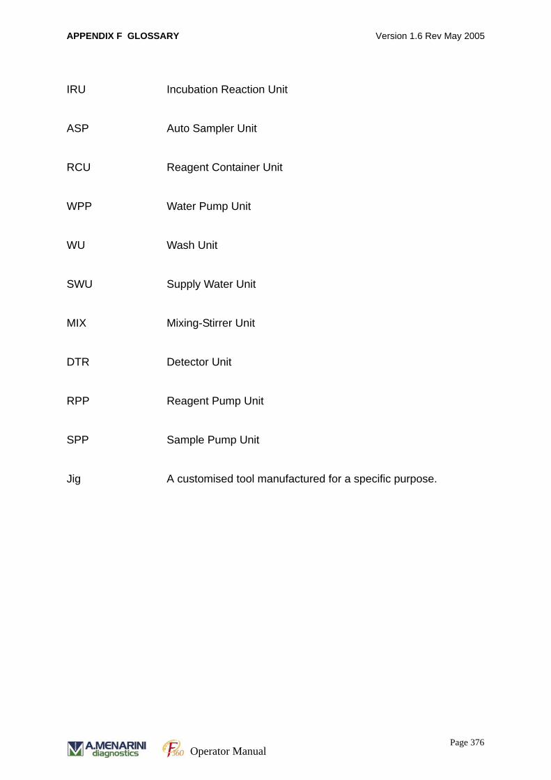
APPENDIX F GLOSSARY Version 1.6 Rev May 2005
IRU Incubation Reaction Unit
ASP Auto Sampler Unit
RCU Reagent Container Unit
WPP Water Pump Unit
WU Wash Unit
SWU Supply Water Unit
MIX Mixing-Stirrer Unit
DTR Detector Unit
RPP Reagent Pump Unit
SPP Sample Pump Unit
Jig A customised tool manufactured for a specific purpose.
Page 376Operator Manual
APPENDIX G Chemistry Parameter Importing Software Version 1.6 Rev May 2005
APPENDIX G.
Chemistry Parameter Importing Software
G.1 OVERVIEW
The software allows the download of chemistry parameter information from the PC to
the analyser. The software must be installed on a PC with "Analyser" user interface
software installed.
G. 1.1 SOFTWARE VERSIONS
The parameter importing software is updated during software releases so that
compatibility is maintained.
G. 1.2 MAXIMUM CAPACITY
The maximum number of methods that can be handled by "Download" software is
500. When downloading, the numbers of methods is counted at the selection of the
methods and when the total number exceeds 500, an error message "Error reading
master parameter data. 500 is the maximum" is shown. Further downloading
operation cannot be executed.
G. 1.3 LIMITATION
1) The language is English only. Multilingual software is available to users with
Windows XP running on their PC's.
2) "Download" software must be installed on a PC with "Analyser" user interface
software installed.
4) The "Analyser" user interface software must be terminated before running
"Download" software.
Page 377Operator Manual
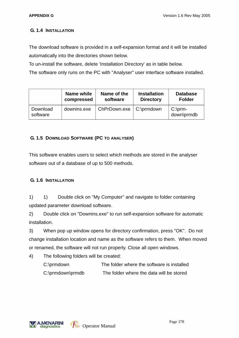
APPENDIX G Version 1.6 Rev May 2005
G. 1.4 INSTALLATION
The download software is provided in a self-expansion format and it will be installed
automatically into the directories shown below.
To un-install the software, delete 'Installation Directory' as in table below.
The software only runs on the PC with "Analyser" user interface software installed.
G. 1.5 DOWNLOAD SOFTWARE (PC TO ANALYSER)
This software enables users to select which methods are stored in the analyser
software out of a database of up to 500 methods.
G. 1.6 INSTALLATION
1) 1) Double click on "My Computer" and navigate to folder containing
updated parameter download software.
2) Double click on "Downins.exe" to run self-expansion software for automatic
installation.
3) When pop up window opens for directory confirmation, press "OK". Do not
change installation location and name as the software refers to them. When moved
or renamed, the software will not run properly. Close all open windows.
4) The following folders will be created:
C:\prmdown The folder where the software is installed
C:\prmdown\prmdb The folder where the data will be stored
Name while compressed
Name of the software
Installation Directory
Database Folder
Download software
downins.exe ChPrDown.exe C:\prmdown C:\prm-down\prmdb
Page 378Operator Manual

APPENDIX G Version 1.6 Rev May 2005
G. 1.7 USER INTERFACE
G. 1.8 OPERATION PROCEDURE
1) Launch 'Analyser' software (click on Start -> Programs -> Analyser ->
Analyser) if not already open.
2) If the analyser had previously been shut down the pop-up window
'Communicating with instrument' appears, click 'Stop', then click 'Cancel' on
the subsequent 'Communication link failed Retry?' pop-up window.
3) Delete unwanted methods as follows:
a. Click on Chemistry Parameters (F6) tab
b. Click on the 'Chemistry Parameters' title field on this screen
c. Enter current engineering code to unlock closed channel and Return
(contact A. MENARINI Diagnostics if you need this)
d. Click in the 'Method' field
e. Press spacebar to display method selection window
f. Double-click on unnecessary closed channel method to select it
Program version no.
METHOD NAME
METHOD NO.
NO. OF REGISTERED METHODSMETHOD NAMESSTORED ON PC
FILEPATH ON PC
Page 379Operator Manual
APPENDIX G Version 1.6 Rev May 2005
g. Click on 'Name' field and delete contents. Press Return. All parameters
for this method should now have reset to their default values.
h. Click on 'Save' to complete deletion of parameters
i. Select System Parameters -> System (F9) [page 1/2]
j. Click on the 'System Parameters' title field on this screen
k. Enter current engineering code and press Return
l. Click in the 'Reagent Code' window on the reagent that you wish to
remove
m. Click on 'Delete'
n. Click on 'Save' to complete deletion
4) Repeat step (3) for all undesired methods
5) When complete terminate 'Analyser' software (see Installation step 1).
G. 1.9 UPDATE PARAMETERS FILE TO LATEST VERSION
1) Ensure latest F360 parameters disk is present in the PC
2) Double click on "My Computer" and navigate to folder containing correct
parameters (prmdb file) for analyser.
NB Parameters are different depending on filter configuration of the analyser.
Please ensure correct version is used else measurements will be taken at
incorrect wavelengths.
a) 660nm optical filter installed
b) 380nm optical filter installed
3) Right click on "prmdb" folder and select Copy. Close open window.
4) Double click "C" then double click "prmdown" folder. Right click in white space
on "prmdown" folder window and select Paste. Confirm that you wish to
replace existing folder by clicking "Yes to All".
Page 380Operator Manual

APPENDIX G Version 1.6 Rev May 2005
G. 1.10 LOAD NEW METHODS INTO ANALYSER
1) Run the Chemistry Parameter Importing Software by double clicking on
"ChPrDown.exe" icon.
2) From the left hand side window, hold down left mouse button and drag
selected method to right hand side window at a blank position. Release the left
mouse button. The name of the method will appear in the selected box with a
white background.
NB Please note that the order selected here defines the order methods appear
in analyser software.
3) After all the desired methods are placed in the right side window, press
"COPY" button to download the information to the analyser. The background
of the transferred methods will appear in grey after transfer.
4) Terminate the software and close all open windows.
5) Restart PC (click Start -> Shut Down -> Restart -> OK)
6) Turn the Clinical Chemistry Analyser OFF then ON again with the main power
switch.
7) Once 'Analyser' software has loaded, click on Chemistry Prm (F6) tab, select
method field and press spacebar to confirm desired methods have been
transferred successfully to the analyser.
G. 1.11 UPDATE EXISTING METHODS STORED IN ANALYSER
1) Run the Chemistry Parameter Importing Software by double clicking on
"ChPrDown.exe" icon.
2) From the left hand side window, select the method name to be updated, hold
down left mouse button and drag to right hand side window over the same
method name. Release the left mouse button. The name of the updated
method will appear in the selected box with a white background.
Page 381Operator Manual
APPENDIX G Version 1.6 Rev May 2005
NB Please note that the order selected here defines the order methods appear
in analyser software.
3) After all the desired methods have been updated, press "COPY" button to
download the information to the analyser. The background of the transferred
methods will appear in grey after transfer.
4) Terminate the software and close all open windows.
5) Restart PC (click Start -> Shut Down -> Restart -> OK)
6) Turn the Clinical Chemistry Analyser OFF then ON again with the main power
switch.
7) Once 'Analyser' software has loaded, click on Chemistry Prm (F6) tab, select
method field and press spacebar to confirm desired methods have been
transferred successfully to the analyser.
Page 382Operator Manual

APPENDIX G Version 1.6 Rev May 2005
Page 383Operator Manual

APPENDIX G Version 1.6 Rev May 2005
Page 384Operator Manual