Embed Size (px)
Citation preview
F300EElectronic Air Cleaner
PRODUCT DATA
® U.S. Registered TrademarkCopyright © 2000 Honeywell • All Rights Reserved
APPLICATIONThe F300E Electronic Air Cleaner is mounted in the returnair duct of a forced air heating, cooling, or ventilating system.It captures a significant amount of the airborne particles 0.3microns and larger from the air circulated through it.
FEATURES• Available in four sizes to fit most ducts; adapts to
airflow from either side.• Capacity varies from 1200 cfm (2040 m3/hr) to
2000 cfm (3400 m3/hr), depending on size.• Solid state power supply is self-regulating and
maintains peak efficiency during a wide range ofcell dirt loading conditions.
• Pressure drop is approximately equal to that of aregular fiberglass filter.
• Optional W8600F Air Cleaner Monitor indicates aircleaner performance, reminds homeowner when acell and prefilter wash is due, and when to checkthe system.
• Optional wireless W8600A AIRWATCH™ LCDindicator provides reminder when air cleanerelectronic cells need washing, as well as reminderwhen UV lamps need replacing and when humidifierpad needs replacing.
• Galvanized cabinet protects against rust.• Neon light next to on-off switch tells if air cleaner is
powered and if high voltage is present.• Prefilter screens protect cells from large dirt
particles.
Contents
Application ........................................................................ 1Features ............................................................................ 1Specifications.................................................................... 2Ordering Information......................................................... 2Planning the Installation ................................................... 4Installation ......................................................................... 7Operation .......................................................................... 13Checkout ........................................................................... 13Service .............................................................................. 13Replacement Parts/Exploded View .................................. 18Electrical Troubleshooting ................................................. 20
68-0240-1
F300E ELECTRONIC AIR CLEANER
68-0240-1 2
SPECIFICATIONSIMPORTANT
The specifications given in this publication do notinclude normal manufacturing tolerances.Therefore, this unit may not exactly match the listedspecifications. This product is tested and calibratedunder closely controlled conditions, and someminor differences in performance can be expected ifthose conditions are changed.
Model:Electronic Air Cleaner: Includes cabinet, access door, solidstate power supply, two electronic cells and two prefilters.
Electrical Ratings:Voltage and Frequency: 120V, 60 Hz. Can be converted in
the field to 240V, 60 Hz or 220/240V,50 Hz with the 203365A Conversion Kit.
Power Consumption: 36W maximum.Current Draw: See Table 1.Ionizer Voltage: 8150 Vdc.Collector Voltage: 4075 Vdc.
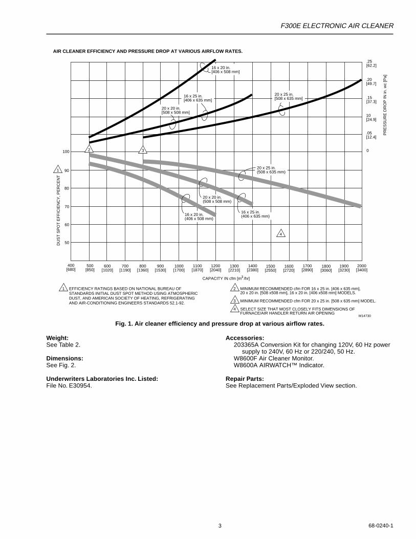
Capacity, Efficiency, Pressure Drop:See Fig. 1, for capacity, pressure drop and ASHRAE dustspot efficiencies.
Fractional Efficiency:70% efficient on 0.3 micron particles at 500 fpm.90% efficient on 1.0 micron particles at 500 fpm.99% efficient on 10.0 micron particles at 500 fpm.
Temperature Ratings:Operating Ambient: 40° to 125°F (4° to 52°C).Temperature of Airflow Through Cells: 40° to 125°F
(4° to 52°C).Maximum Cell Washing Temperature: 220°F (140°C).Storage and Shipping Ambient: Minus 40°F to plus 140°F
(minus 40°C to plus 60°C).
Mounting:Mounts in the return air duct of a forced air heating, cooling,or ventilating system. Mount upstream from the atomizinghumidifier. See the Planning the Installation section.
Table 1. Current Draw.
Table 2. Shipping and Installation Weight.
ORDERING INFORMATION
When purchasing replacement and modernization products from your TRADELINE® wholesaler or distributor, refer to theTRADELINE® Catalog or price sheets for complete ordering number, or specify1. Order number.2. Voltage and frequency.3. Dimensions: 16 x 20, 16 x 25, 20 x 20, or 20 x 25 in. (406 x 508, 406 x 635, 508 x 508, or 508 x 635 mm).4. Conversion kit for changing two cell 120V, 60 Hz models to 240V, 60 Hz or 220/240V, 50 Hz.5. W8600F Air Cleaner Monitor, if desired.
6. W8600A AIRWATCH™ Indicator, if desired.
If you have additional questions, need further information, or would like to comment on our products or services, please writeor phone:1. Home and Building Control Customer Assistance
Honeywell, 1885 Douglas Drive NorthGolden Valley, MN 55422-4386 (612) 951-1000
2. Visit our web site @ www.honeywell.com/yourhome/
In Canada—Honeywell Limited/Honeywell Limitée, 155 Gordon Baker Road, North York, Ontario M2H 3N7.International Sales and Service Offices in all principal cities of the world. Manufacturing in Australia, Canada, Finland, France,Germany, Japan, Mexico, Netherlands, Spain, Taiwan, United Kingdom, U.S.A.
Max. Current (A)
Size No. 220/in. mm Cells 120V 240V
16 x 20 406 x 508 2 0.4 0.2
16 x 25 406 x 635 2 0.4 0.2
20 x 20 508 x 508 2 0.4 0.2
20 x 25 508 x 635 2 0.4 0.2
Weight
16 x 20 in.(406 x 508 mm)
16 x 25 in.(406 x 635 mm)
20 x 20 in. (508 x 508 mm)
20 x 25 in.(508 x 635 mm)
lb kg lb kg lb kg lb kg
Electronic Cell (Each) 5 2.25 6 2.7 6-3/16 2.8 7-1/2 3.4
Shipping Weight 30 13.6 33 15.0 33 15.0 38 17.2
Installed Weight (Cells Included)
26 11.6 28 12.7 29 13.2 33 15.0
F300E ELECTRONIC AIR CLEANER
68-0240-13
Fig. 1. Air cleaner efficiency and pressure drop at various airflow rates.
Weight:See Table 2.
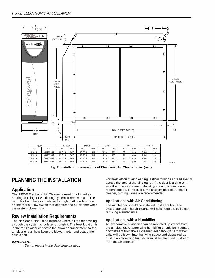
Dimensions:See Fig. 2.
Underwriters Laboratories Inc. Listed:File No. E30954.
Accessories:203365A Conversion Kit for changing 120V, 60 Hz power
supply to 240V, 60 Hz or 220/240, 50 Hz.W8600F Air Cleaner Monitor.W8600A AIRWATCH™ Indicator.
Repair Parts:See Replacement Parts/Exploded View section.
CAPACITY IN cfm [m /hr]3
1 EFFICIENCY RATINGS BASED ON NATIONAL BUREAU OF STANDARDS INITIAL DUST SPOT METHOD USING ATMOSPHERIC DUST, AND AMERICAN SOCIETY OF HEATING, REFRIGERATING AND AIR-CONDITIONING ENGINEERS STANDARDS 52.1-92.
2 MINIMUM RECOMMENDED cfm FOR 16 x 25 in. [406 x 635 mm], 20 x 20 in. [508 x508 mm], 16 x 20 in. [406 x508 mm] MODELS.
3 MINIMUM RECOMMENDED cfm FOR 20 x 25 in. [508 x 635 mm] MODEL.
4 SELECT SIZE THAT MOST CLOSELY FITS DIMENSIONS OF FURNACE/AIR HANDLER RETURN AIR OPENING
M14730
700[1190]
800[1360]
900[1530]
1000[1700]
1100[1870]
1200[2040]
1300[2210]
1400[2380]
1500[2550]
1600[2720]
1700[2890]
1800[3060]
1900[3230]
2000[3400]
.25[62.2]
.20[49.7]
.15[37.3]
10[24.9]
.05[12.4]
0
PR
ES
SU
RE
DR
OP
IN in
. wc
[Pa]
50
60
70
80
90
100
DU
ST
SP
OT
EF
FIC
IEN
CY
, PE
RC
EN
T
600[1020]
500[850]
400[680]
1
4
20 x 20 in.[508 x 508 mm]
16 x 25 in.[406 x 635 mm]
16 x 20 in.[406 x 508 mm]
20 x 20 in.(508 x 508 mm)
16 x 20 in.(406 x 508 mm)
16 x 25 in.(406 x 635 mm)
2 3
20 x 25 in.[508 x 635 mm]
20 x 25 in.(508 x 635 mm)
AIR CLEANER EFFICIENCY AND PRESSURE DROP AT VARIOUS AIRFLOW RATES.
F300E ELECTRONIC AIR CLEANER
68-0240-1 4
Fig. 2. Installation dimensions of Electronic Air Cleaner in in. (mm).
PLANNING THE INSTALLATION
ApplicationThe F300E Electronic Air Cleaner is used in a forced airheating, cooling, or ventilating system. It removes airborneparticles from the air circulated through it. All models havean internal air flow switch that operates the air cleaner whenthe system blower is on.
Review Installation RequirementsThe air cleaner should be installed where all the air passingthrough the system circulates through it. The best location isin the return air duct next to the blower compartment so theair cleaner can help keep the blower motor and evaporatorcoils clean.
IMPORTANTDo not mount in the discharge air duct.
For most efficient air cleaning, airflow must be spread evenlyacross the face of the air cleaner. If the duct is a differentsize than the air cleaner cabinet, gradual transitions arerecommended. If the duct turns sharply just before the aircleaner, turning vanes are recommended.
Applications with Air ConditioningThe air cleaner should be installed upstream from theevaporator coil. The air cleaner will help keep the coil clean,reducing maintenance.
Applications with a HumidifierAn evaporative humidifier can be mounted upstream fromthe air cleaner. An atomizing humidifier should be mounteddownstream from the air cleaner, even though hard watersalts will be blown into the living space and deposited asdust. If an atomizing humidifier must be mounted upstreamfrom the air cleaner:
M14731
F300IN.
16 X 25
16 X 20
20 X 25
20 X 20
MM
406 X 635
406 X 508
508 X 635
508 X 508
DIM. A
14 7/16
14 7/16
18 7/16
18 7/16
367
367
468
468
DIM. B
16 3/16
16 3/16
20 3/16
20 3/16
411
411
513
513
23 1/4
18 1/4
23 1/4
18 1/4
DIM. C
591
457
591
457
DIM. D
25
20
25
20
626
509
626
509
DIM. C (SEE TABLE)
DIM. D (SEE TABLE)
DIM. B(SEE TABLE)
58
(16)6
34
(172)2-1/2(63)
DIM. A(SEE
TABLE)
78
(22)
IN. MM IN. MM IN. MM IN. MM
DIM. E(SEE TABLE)
38 (162)
6
DIM. E
2 3/4
2 3/4
2 3/4
2 3/4
70
70
70
70
IN. MM
SYSTEM
F300E ELECTRONIC AIR CLEANER
68-0240-15
1. Mount it as far as possible upstream from the aircleaner.
2. Install a standard disposable furnace filter between thehumidifier and the air cleaner to trap water dropletsand hard water salts.
3. Frequently clean the air cleaner to prevent a hardwater salt buildup.
NOTE: The volume of water that passes through anatomizing humidifier can overload the aircleaner, resulting in hard water salts beingdeposited as dust in the living space.
Applications with an Activated Carbon FilterAn activated carbon (charcoal) filter can be used to removeodors or other gaseous contaminants (not particle-based)that are not removed by the air cleaner. Locate the carbonfilter:• Downstream from the air cleaner. This means that dust
from the carbon filter will not be collected by the aircleaner and will be deposited in the living space.
• Outside the air cleaner cabinet. Some carbon filters arecombustible and contact with high voltage could result insmoke or fire.
• Where carbon granules cannot fall into the electronic cell.If necessary, use a disposable furnace filter between thecarbon filter and the electronic cell.
• With proper transitions, if the activated carbon filterrequires a differently sized duct than the air cleaner. Allow20 degrees expansion per side, per fitting.
NOTE: Honeywell does not offer carbon filters. Refer toan activated carbon filter manufacturer for sizingand application.
Applications with Outdoor Air IntakeReturn air temperature must be at least 40°F (4°C). Lowertemperatures can cause ionizer wire failure. If outdoor air isused, warm it upstream from the air cleaner by:• Making sure the outdoor intake is far enough upstream
from the air cleaner so the return and outdoor air isthoroughly mixed. Stratified air can dump a stream of verycold air into one section of the air cleaner.
• Adding baffles upstream from the air cleaner to forcethorough air mixing.
• Installing a Honeywell Home Ventilation System thattransfers up to 80 percent of the heat from the exhaust airto the incoming outside air. This keeps the incoming airabove 40°F (4°C) and reduces energy usage.
• Installing a preheater if large amounts of outdoor air areused. The preheater, which could be an electric stripheater or hot water coil, should be controlled by athermostat. Hot water or steam coils should be protectedby a freeze-up control.
Optional W8600F Air Cleaner MonitorThe terminal board is recessed slightly so it or the wires willnot interfere with installation. The entire power supply boxcan be unplugged and removed to provide access to theterminals. The W8600F Air Cleaner Monitor can be mountedin the living area or in the furnace room. It should be locatedin a convenient location to observe the display.
Optional W8600A AIRWATCH™ IndicatorThe W8600A can be mounted next to the thermostat or inany other location in the living area of the home where thedisplay can be conveniently observed. No wiring isnecessary.
Choose LocationChoose a location that is readily accessible for regularinspection and cleaning. Allow at least 13 in. (330 mm) infront of the access door for removing the prefilter andelectronic cell. Allow enough room above the power supplyso it can be serviced without removing pipes, ducts, or otherheating system components.
The air cleaner must be installed where the temperature willnot exceed 40° to 125°F (4° to 52°C).
Choose Mounting Position
WARNINGHeavy Equipment.Can cause injury or equipment damage.Do not mount the air cleaner with the access doorfacing down. If the access door faces down, the latchmay not hold, and the cell and prefilter can fallunexpectedly. Also, nothing holds the cell andprefilter in place when the access door is opened.
The air cleaner can be mounted in any position except withthe access door facing down. Following is a list of air cleanermounting positions for a variety of furnace installations.
NOTE: At least 13 in. (330 mm) clearance is requiredbetween the access door and any obstructionsfor cell and prefilter maintenance.
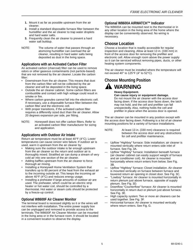
— Upflow “Highboy” furnace: Side installation; air cleaner ismounted vertically where return enters side inlet offurnace. See Fig. 3A.
— Upflow “Highboy” furnace: Installation beneath furnace(air cleaner cabinet can easily support weight of furnaceand air conditioner coil). Air cleaner is mountedhorizontally where return enters from below. See Fig.3B.
— Upflow “Highboy” furnace: Closet installation. Air cleaneris mounted vertically on furnace between furnace andlouvered return air opening in closet door. See Fig. 3C.
— “Lowboy” furnace: Air cleaner is mounted horizontally inreturn plenum just above furnace, opposite of supplyplenum. See Fig. 3D.
— Downflow “Counterflow” furnace: Air cleaner is mountedhorizontally in return duct or plenum just above furnace.See Fig. 3E.
— High capacity system: Two or more air cleaners can beused together. See Fig. 3F.
— Horizontal furnace: Air cleaner is mounted verticallywhere return enters. See Fig. G.
F300E ELECTRONIC AIR CLEANER
68-0240-1 6
Fig. 3. Mounting positions with variety of furnace installations.
Determine Duct Design RequirementsThe air cleaner is adaptable to all new or existing forced airheating, cooling and ventilating systems used in residentialapplications. Transitions, turning vanes, or offsets may beneeded in some applications for effective operation.
TransitionsTransitions are needed when the duct is a different size thanthe air cleaner cabinet. Gradual transitions reduce airturbulence and increase efficiency. Limit expansion to nomore than 20 degrees or about 4 in. per running foot (100mm per 300 linear mm) on each side of a transition fitting.See Fig. 4.
Turning VanesIf the air cleaner is installed close to an elbow or anglefitting, install turning vanes inside the angle to distributeairflow more evenly across the face of the cell. See Fig. 5.
OffsetsIf the duct connection to the furnace in a side installationallows less than 7 in. (178 mm) for mounting the air cleanercabinet, add an offset to the elbow. See Fig. 5.
Fig. 4. Change duct size graduallyto minimize turbulence.
20 DEGREE EXPANSION PER SIDE PER FITTING (4 in. PER LINEAR FOOT [100 mm PER 300 LINEAR mm]).
RETURN AIR DUCT
TRANSITION FITTING
ELECTRONIC AIR CLEANER CABINET M5626A
CHANGE DUCT SIZE GRADUALLY TO MINIMIZE TURBULENCE.
M14732A
AB
CD
E
F G
M14733
LESSTHAN7 in.(178 mm)
OFFSET
AT LEAST7 in.(178 mm)
1
1 TURNING VANES HELP DISTRIBUTE AIRFLOW EVENLY.
TYPICAL USE OF DUCT OFFSET TO ALLOW SPACE FOR ELECTRONIC AIR CLEANER.
Fig. 5. Typical use of duct offset to allowspace for electronic air cleaner.
F300E ELECTRONIC AIR CLEANER
68-0240-17
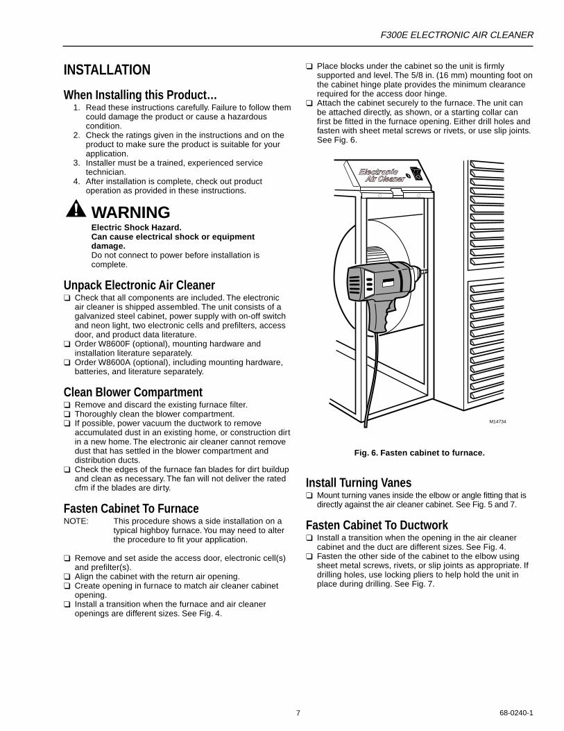
❑ Place blocks under the cabinet so the unit is firmlysupported and level. The 5/8 in. (16 mm) mounting foot onthe cabinet hinge plate provides the minimum clearancerequired for the access door hinge.
❑ Attach the cabinet securely to the furnace. The unit canbe attached directly, as shown, or a starting collar canfirst be fitted in the furnace opening. Either drill holes andfasten with sheet metal screws or rivets, or use slip joints.See Fig. 6.
INSTALLATION
When Installing this Product…1. Read these instructions carefully. Failure to follow them
could damage the product or cause a hazardouscondition.
2. Check the ratings given in the instructions and on theproduct to make sure the product is suitable for yourapplication.
3. Installer must be a trained, experienced servicetechnician.
4. After installation is complete, check out productoperation as provided in these instructions.
WARNINGElectric Shock Hazard.Can cause electrical shock or equipmentdamage.Do not connect to power before installation iscomplete.
Unpack Electronic Air Cleaner❑ Check that all components are included. The electronic
air cleaner is shipped assembled. The unit consists of agalvanized steel cabinet, power supply with on-off switchand neon light, two electronic cells and prefilters, accessdoor, and product data literature.
❑ Order W8600F (optional), mounting hardware andinstallation literature separately.
❑ Order W8600A (optional), including mounting hardware,batteries, and literature separately.
Clean Blower Compartment❑ Remove and discard the existing furnace filter.❑ Thoroughly clean the blower compartment.❑ If possible, power vacuum the ductwork to remove
accumulated dust in an existing home, or construction dirtin a new home. The electronic air cleaner cannot removedust that has settled in the blower compartment anddistribution ducts.
❑ Check the edges of the furnace fan blades for dirt buildupand clean as necessary. The fan will not deliver the ratedcfm if the blades are dirty.
Fasten Cabinet To FurnaceNOTE: This procedure shows a side installation on a
typical highboy furnace. You may need to alterthe procedure to fit your application.
❑ Remove and set aside the access door, electronic cell(s)and prefilter(s).
❑ Align the cabinet with the return air opening.❑ Create opening in furnace to match air cleaner cabinet
opening.❑ Install a transition when the furnace and air cleaner
openings are different sizes. See Fig. 4.
Fig. 6. Fasten cabinet to furnace.
Install Turning Vanes❑ Mount turning vanes inside the elbow or angle fitting that is
directly against the air cleaner cabinet. See Fig. 5 and 7.
Fasten Cabinet To Ductwork❑ Install a transition when the opening in the air cleaner
cabinet and the duct are different sizes. See Fig. 4.❑ Fasten the other side of the cabinet to the elbow using
sheet metal screws, rivets, or slip joints as appropriate. Ifdrilling holes, use locking pliers to help hold the unit inplace during drilling. See Fig. 7.
M14734
F300E ELECTRONIC AIR CLEANER
68-0240-1 8
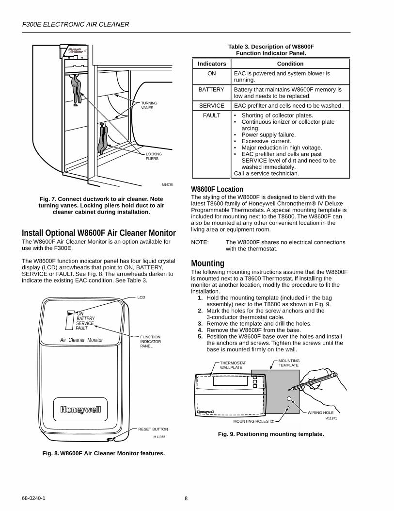
Fig. 7. Connect ductwork to air cleaner. Noteturning vanes. Locking pliers hold duct to air
cleaner cabinet during installation.
Install Optional W8600F Air Cleaner MonitorThe W8600F Air Cleaner Monitor is an option available foruse with the F300E.
The W8600F function indicator panel has four liquid crystaldisplay (LCD) arrowheads that point to ON, BATTERY,SERVICE or FAULT. See Fig. 8. The arrowheads darken toindicate the existing EAC condition. See Table 3.
Table 3. Description of W8600FFunction Indicator Panel.
ONBATTERYSERVICEFAULT
Air Cleaner MonitorFUNCTIONINDICATORPANEL
LCD
RESET BUTTON
M11965
W8600F LocationThe styling of the W8600F is designed to blend with thelatest T8600 family of Honeywell Chronotherm® IV DeluxeProgrammable Thermostats. A special mounting template isincluded for mounting next to the T8600. The W8600F canalso be mounted at any other convenient location in theliving area or equipment room.
NOTE: The W8600F shares no electrical connectionswith the thermostat.
MountingThe following mounting instructions assume that the W8600Fis mounted next to a T8600 Thermostat. If installing themonitor at another location, modify the procedure to fit theinstallation.
1. Hold the mounting template (included in the bagassembly) next to the T8600 as shown in Fig. 9.
2. Mark the holes for the screw anchors and the3-conductor thermostat cable.
3. Remove the template and drill the holes.4. Remove the W8600F from the base.5. Position the W8600F base over the holes and install
the anchors and screws. Tighten the screws until thebase is mounted firmly on the wall.
M11971
THERMOSTATWALLPLATE
MOUNTINGTEMPLATE
MOUNTING HOLES (2)
WIRING HOLE
M14735
LOCKINGPLIERS
TURNINGVANES
SYSTEM
Fig. 8. W8600F Air Cleaner Monitor features.
Fig. 9. Positioning mounting template.
Indicators Condition
ON EAC is powered and system blower isrunning.
BATTERY Battery that maintains W8600F memory islow and needs to be replaced.
SERVICE EAC prefilter and cells need to be washed .
FAULT • Shorting of collector plates.• Continuous ionizer or collector plate
arcing.• Power supply failure.• Excessive current.• Major reduction in high voltage.• EAC prefilter and cells are past
SERVICE level of dirt and need to bewashed immediately.
Call a service technician.
F300E ELECTRONIC AIR CLEANER
68-0240-19
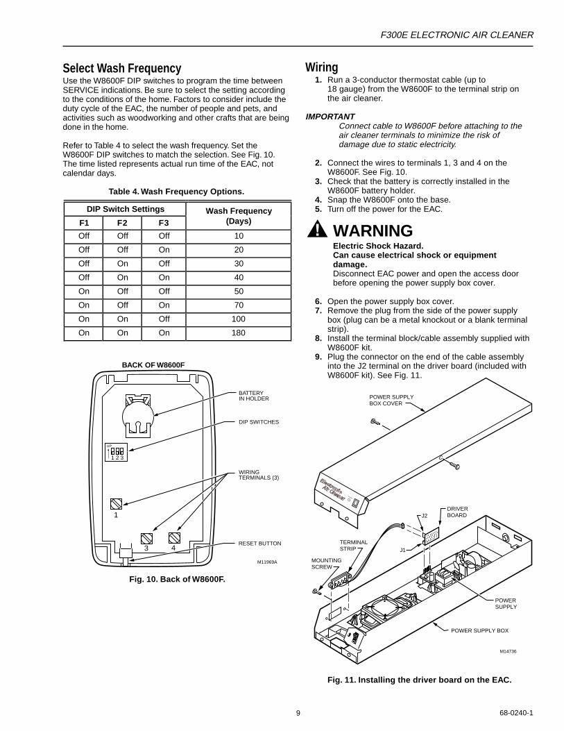
Select Wash FrequencyUse the W8600F DIP switches to program the time betweenSERVICE indications. Be sure to select the setting accordingto the conditions of the home. Factors to consider include theduty cycle of the EAC, the number of people and pets, andactivities such as woodworking and other crafts that are beingdone in the home.
Refer to Table 4 to select the wash frequency. Set theW8600F DIP switches to match the selection. See Fig. 10.The time listed represents actual run time of the EAC, notcalendar days.
Table 4. Wash Frequency Options.
Wiring1. Run a 3-conductor thermostat cable (up to
18 gauge) from the W8600F to the terminal strip onthe air cleaner.
IMPORTANTConnect cable to W8600F before attaching to theair cleaner terminals to minimize the risk ofdamage due to static electricity.
2. Connect the wires to terminals 1, 3 and 4 on theW8600F. See Fig. 10.
3. Check that the battery is correctly installed in theW8600F battery holder.
4. Snap the W8600F onto the base.5. Turn off the power for the EAC.
WARNINGElectric Shock Hazard.Can cause electrical shock or equipmentdamage.Disconnect EAC power and open the access doorbefore opening the power supply box cover.
6. Open the power supply box cover.7. Remove the plug from the side of the power supply
box (plug can be a metal knockout or a blank terminalstrip).
8. Install the terminal block/cable assembly supplied withW8600F kit.
9. Plug the connector on the end of the cable assemblyinto the J2 terminal on the driver board (included withW8600F kit). See Fig. 11.
Fig. 10. Back of W8600F.
M11969A
BATTERYIN HOLDER
DIP SWITCHES
RESET BUTTON
WIRING TERMINALS (3)
BACK OF W8600F
1
3 4
1 2 3
UP
DIP Switch Settings Wash FrequencyF1 F2 F3 (Days)
Off Off Off 10
Off Off On 20
Off On Off 30
Off On On 40
On Off Off 50
On Off On 70
On On Off 100
On On On 180
M14736
J2
J1
DRIVERBOARD
TERMINALSTRIP
MOUNTINGSCREW
POWER SUPPLY BOX
POWER SUPPLY BOX COVER
POWER SUPPLY
SYSTEM
Fig. 11. Installing the driver board on the EAC.
F300E ELECTRONIC AIR CLEANER
68-0240-1 10
10. Plug the driver board assembly into the J1 powersupply connector.
11. Replace the power supply box cover.12. Connect the three wires from the W8600F to the EAC
terminals 1, 3 and 4. See Fig 12.
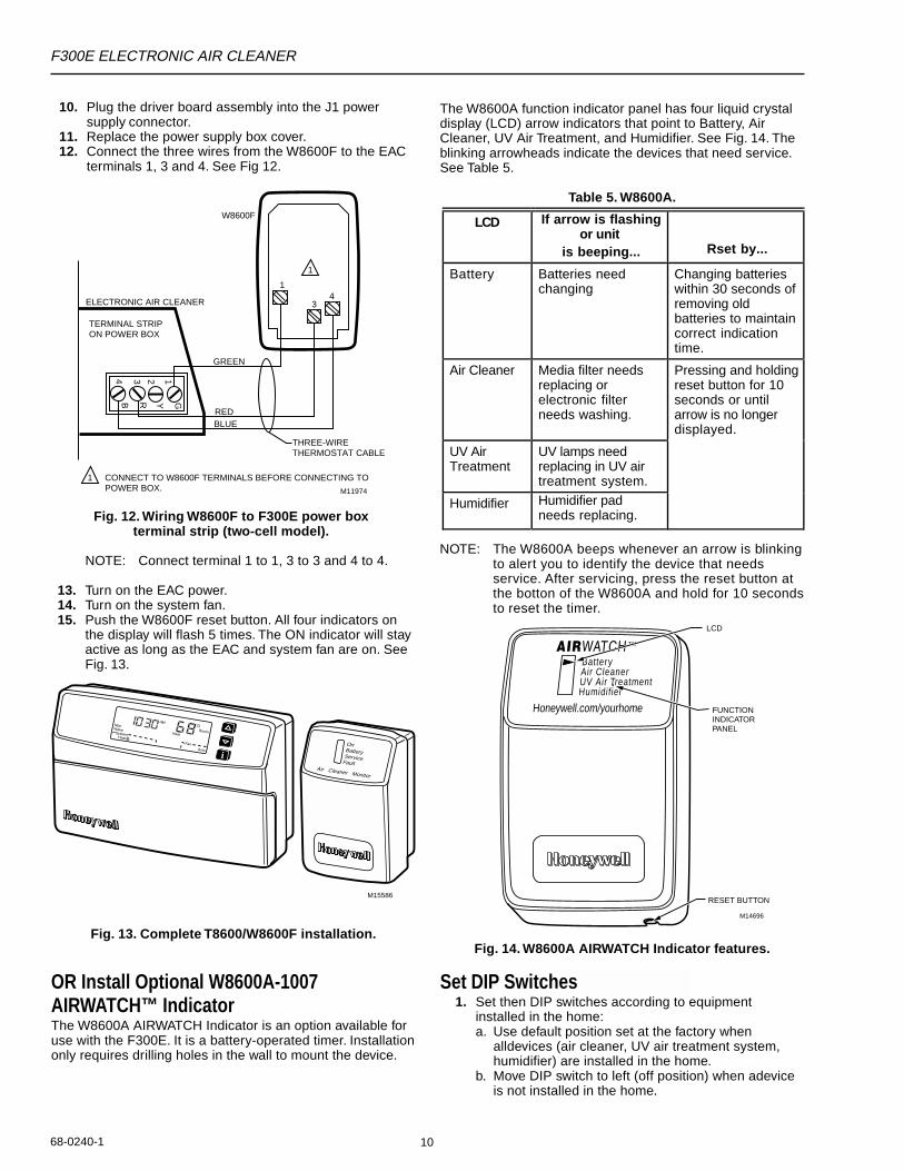
The W8600A function indicator panel has four liquid crystaldisplay (LCD) arrow indicators that point to Battery, AirCleaner, UV Air Treatment, and Humidifier. See Fig. 14. Theblinking arrowheads indicate the devices that need service.See Table 5.
Table 5. W8600A.
M11974
TERMINAL STRIP ON POWER BOX
THREE-WIRETHERMOSTAT CABLE
GREEN
REDBLUE
1234
GYRB
1
1 CONNECT TO W8600F TERMINALS BEFORE CONNECTING TOPOWER BOX.
ELECTRONIC AIR CLEANER
W8600F
1
34
Fig. 12. Wiring W8600F to F300E power boxterminal strip (two-cell model).
NOTE: Connect terminal 1 to 1, 3 to 3 and 4 to 4.
13. Turn on the EAC power.14. Turn on the system fan.15. Push the W8600F reset button. All four indicators on
the display will flash 5 times. The ON indicator will stayactive as long as the EAC and system fan are on. SeeFig. 13.
Fig. 14. W8600A AIRWATCH Indicator features.
Set DIP Switches1. Set then DIP switches according to equipment
installed in the home:a. Use default position set at the factory when
alldevices (air cleaner, UV air treatment system,humidifier) are installed in the home.
b. Move DIP switch to left (off position) when adeviceis not installed in the home.
M15586
OnBatteryServiceFault
Air Cleaner Monitor
Fig. 13. Complete T8600/W8600F installation.
OR Install Optional W8600A-1007AIRWATCH™ IndicatorThe W8600A AIRWATCH Indicator is an option available foruse with the F300E. It is a battery-operated timer. Installationonly requires drilling holes in the wall to mount the device.
Battery
TM
Air CleanerUV Air TreatmentHumidifier
Honeywell.com/yourhome FUNCTIONINDICATORPANEL
LCD
RESET BUTTON
M14696
NOTE: The W8600A beeps whenever an arrow is blinkingto alert you to identify the device that needsservice. After servicing, press the reset button atthe botton of the W8600A and hold for 10 secondsto reset the timer.
LCD If arrow is flashingor unit
is beeping... Rset by...
Battery Batteries needchanging
Changing batterieswithin 30 seconds ofremoving oldbatteries to maintaincorrect indicationtime.
Air Cleaner Media filter needsreplacing orelectronic filterneeds washing.
Pressing and holdingreset button for 10seconds or untilarrow is no longerdisplayed.
UV AirTreatment
UV lamps needreplacing in UV airtreatment system.
Humidifier Humidifier padneeds replacing.
F300E ELECTRONIC AIR CLEANER
68-0240-111
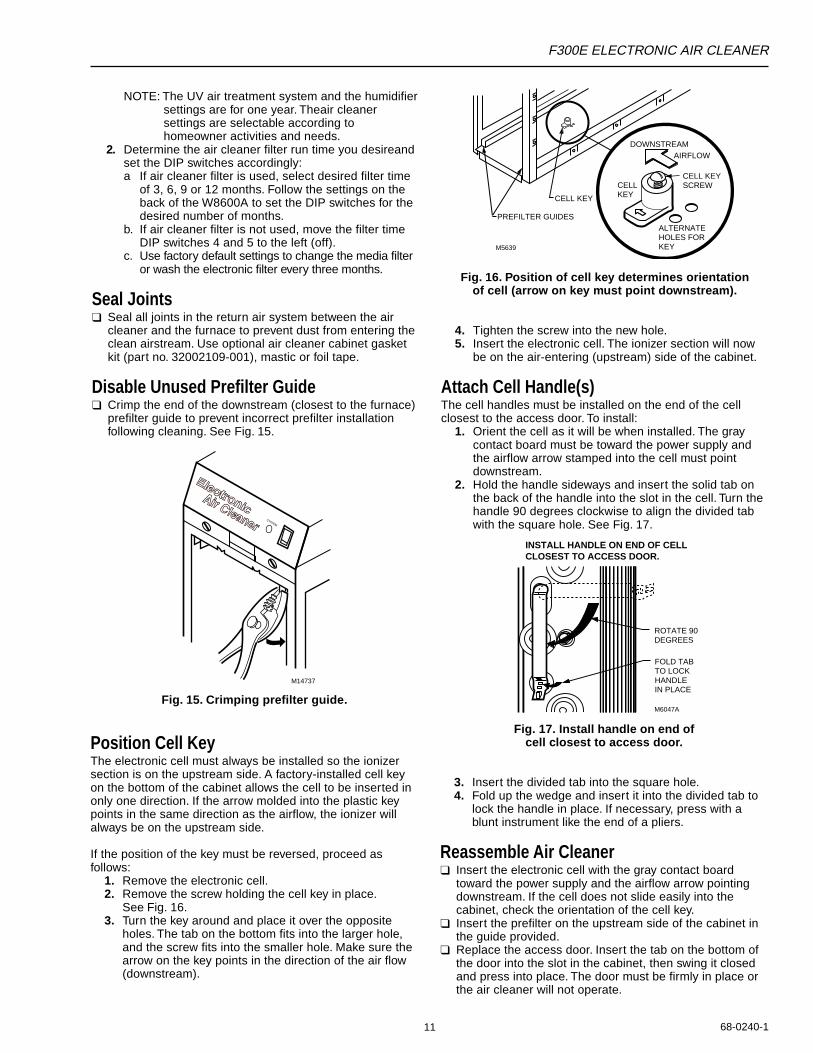
Fig. 16. Position of cell key determines orientationof cell (arrow on key must point downstream).
4. Tighten the screw into the new hole.5. Insert the electronic cell. The ionizer section will now
be on the air-entering (upstream) side of the cabinet.
Attach Cell Handle(s)The cell handles must be installed on the end of the cellclosest to the access door. To install:
1. Orient the cell as it will be when installed. The graycontact board must be toward the power supply andthe airflow arrow stamped into the cell must pointdownstream.
2. Hold the handle sideways and insert the solid tab onthe back of the handle into the slot in the cell. Turn thehandle 90 degrees clockwise to align the divided tabwith the square hole. See Fig. 17.
PREFILTER GUIDES
CELL KEY
M5639
CELL KEY
ALTERNATEHOLES FORKEY
CELL KEYSCREW
DOWNSTREAMAIRFLOW
M6047A
ROTATE 90 DEGREES
FOLD TABTO LOCK HANDLEIN PLACE
INSTALL HANDLE ON END OF CELL CLOSEST TO ACCESS DOOR.
M14737
SYSTEM
NOTE: The UV air treatment system and the humidifiersettings are for one year. Theair cleanersettings are selectable according tohomeowner activities and needs.
2. Determine the air cleaner filter run time you desireandset the DIP switches accordingly:a If air cleaner filter is used, select desired filter time
of 3, 6, 9 or 12 months. Follow the settings on theback of the W8600A to set the DIP switches for thedesired number of months.
b. If air cleaner filter is not used, move the filter timeDIP switches 4 and 5 to the left (off).
c. Use factory default settings to change the media filteror wash the electronic filter every three months.
Seal Joints❑ Seal all joints in the return air system between the air
cleaner and the furnace to prevent dust from entering theclean airstream. Use optional air cleaner cabinet gasketkit (part no. 32002109-001), mastic or foil tape.
Disable Unused Prefilter Guide❑ Crimp the end of the downstream (closest to the furnace)
prefilter guide to prevent incorrect prefilter installationfollowing cleaning. See Fig. 15.
Fig. 15. Crimping prefilter guide.
Position Cell KeyThe electronic cell must always be installed so the ionizersection is on the upstream side. A factory-installed cell keyon the bottom of the cabinet allows the cell to be inserted inonly one direction. If the arrow molded into the plastic keypoints in the same direction as the airflow, the ionizer willalways be on the upstream side.
If the position of the key must be reversed, proceed asfollows:
1. Remove the electronic cell.2. Remove the screw holding the cell key in place.
See Fig. 16.3. Turn the key around and place it over the opposite
holes. The tab on the bottom fits into the larger hole,and the screw fits into the smaller hole. Make sure thearrow on the key points in the direction of the air flow(downstream).
Fig. 17. Install handle on end ofcell closest to access door.
3. Insert the divided tab into the square hole.4. Fold up the wedge and insert it into the divided tab to
lock the handle in place. If necessary, press with ablunt instrument like the end of a pliers.
Reassemble Air Cleaner❑ Insert the electronic cell with the gray contact board
toward the power supply and the airflow arrow pointingdownstream. If the cell does not slide easily into thecabinet, check the orientation of the cell key.
❑ Insert the prefilter on the upstream side of the cabinet inthe guide provided.
❑ Replace the access door. Insert the tab on the bottom ofthe door into the slot in the cabinet, then swing it closedand press into place. The door must be firmly in place orthe air cleaner will not operate.
F300E ELECTRONIC AIR CLEANER
68-0240-1 12
P3
P4
P1P2
J3
BLACK
W4 W2 W1 W3
AIRFLOW SWITCH BOARD
ORANGE
GRAY
VIOLET
BLACK
1 INTERLOCK SWITCH.
2 SHORTING BAR.
3 AIRFLOW SWITCH DISABLE JUMPER.
4 OPTIONAL W8600F AIR CLEANER MONITOR. DRIVER BOARD AND CABLE PROVIDED WITH W8600F.
5 NEON LIGHT.M11975
POWERSUPPLY
2
5
BLACK
4
BLACK BLACK
BROWN
BLACK
BLA
CK
WH
ITE
GR
EE
N
3
1
J4
J5J1
J1
BLACK
RED
TESTBUTTON
CONTACTBOARD
RED IONIZER
BLACK COLLECTOR
4
J2
B4
R3
Y2
G1
2
56
GREEN
RED
BLUE
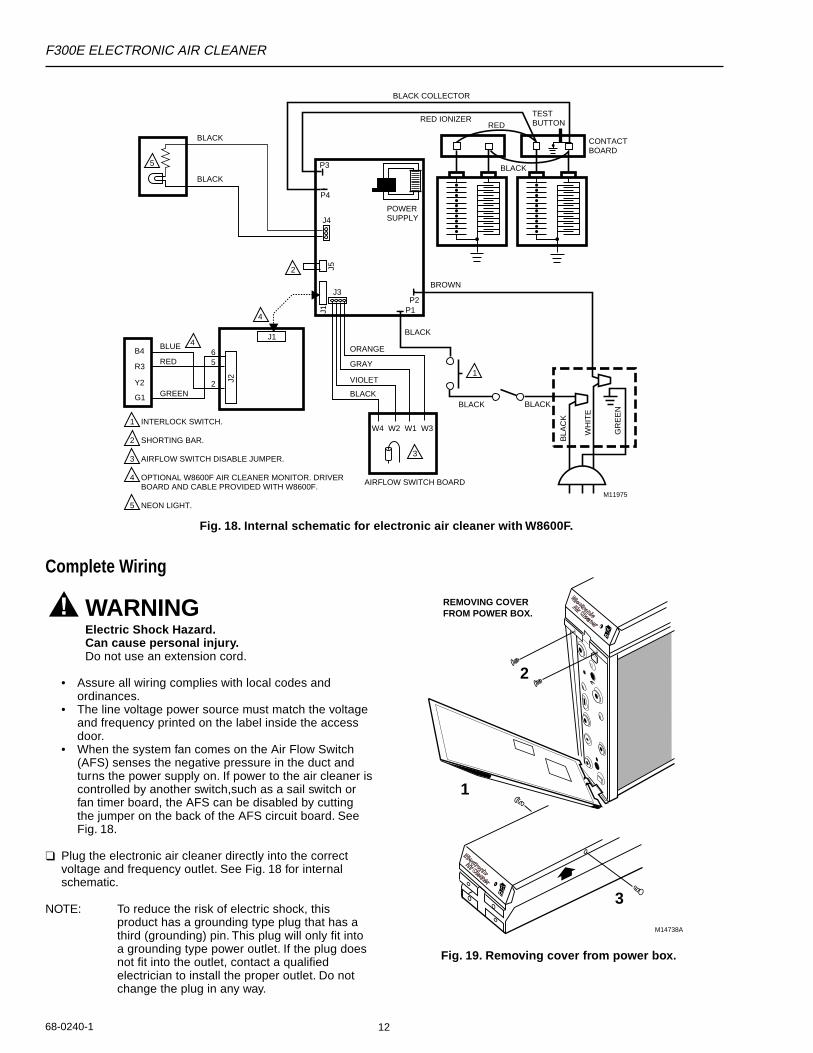
Complete Wiring
WARNINGElectric Shock Hazard.Can cause personal injury.Do not use an extension cord.
• Assure all wiring complies with local codes andordinances.
• The line voltage power source must match the voltageand frequency printed on the label inside the accessdoor.
• When the system fan comes on the Air Flow Switch(AFS) senses the negative pressure in the duct andturns the power supply on. If power to the air cleaner iscontrolled by another switch,such as a sail switch orfan timer board, the AFS can be disabled by cuttingthe jumper on the back of the AFS circuit board. SeeFig. 18.
❑ Plug the electronic air cleaner directly into the correctvoltage and frequency outlet. See Fig. 18 for internalschematic.
NOTE: To reduce the risk of electric shock, thisproduct has a grounding type plug that has athird (grounding) pin. This plug will only fit intoa grounding type power outlet. If the plug doesnot fit into the outlet, contact a qualifiedelectrician to install the proper outlet. Do notchange the plug in any way.
Fig. 18. Internal schematic for electronic air cleaner with W8600F.
Fig. 19. Removing cover from power box.
M14738A
3
1
2
REMOVING COVERFROM POWER BOX.
F300E ELECTRONIC AIR CLEANER
68-0240-113
• Outside air, if used, is mixed with return air or heated, asnecessary, before it can reach the air cleaner.
• Airflow arrows on the electronic cell point downstream.• Prefilter is on the upstream side of the cell.• Cell handle faces outward.• Electronic cell and prefilter are clean and dry.• W8600F (if included) wiring connections are properly
made.
Check Air Cleaner OperationWith all components in place, turn on the air cleaner switchand energize the system blower. Check the following pointsof operation:
1. The neon light next to the on-off switch is on. If aW8600F is part of the installation, also check the wallpanel and make sure the ON indicator is lit. TheW8600F FAULT indicator will come on if there is aproblem with the high voltage power supply.
2. Turn off the system blower. The neon light should gooff after a few seconds. The neon light shows that theair cleaner is energized and the high voltage powersupply is working properly.
3. With a multispeed blower, repeat steps 1 and 2 foreach fan speed.
4. If operation is not as described, refer to theTroubleshooting section.
SERVICE
CAUTIONSharp Edges.Can cause personal injury.Carefully handle the cell(s) or wear protective glovesto avoid cuts from the sharp metal edges.
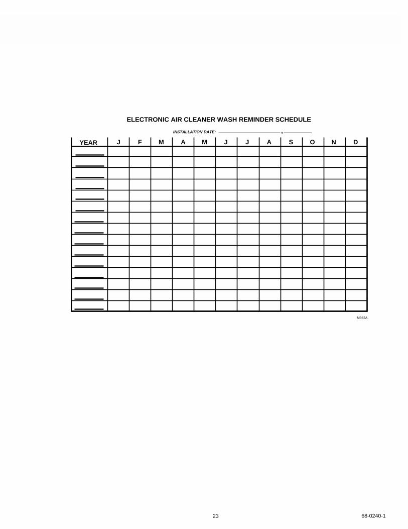
Cleaning the Cell(s) and Prefilter(s)To assure optimum performance from the air cleaner, thecell(s) and prefilter(s) must be cleaned regularly—every oneto six months. Washing frequency will vary depending on thenumber of family members, pets, activities (such as cookingor woodworking) and smoking habits. Use the washreminder schedule on the last page of this document to helpestablish and maintain a regular cleaning schedule. Keepyour wash reminder schedule in a convenient location.
If the air cleaner has a W8600F Air Cleaner Monitor theSERVICE indicator will activate to indicate that it is time towash the prefilter(s) and cell(s). The time between activationof the SERVICE indicator is based on air cleaner run timethat is selected by the installer at installation. See W8600Finstallation instructions, page 8, for instructions on selectingair cleaner run time. Pressing the Reset button on thebottom right corner of the housing resets the W8600FSERVICE indicator. See Fig. 8.
If the air cleaner has a W8600A AIRWATCH Indicator, the AirCleaner LCD arrow will blink to indicate it is time to wash theprefilter(s) and cell(s). The time between activation of the AirCleaner LCD is based on air cleaner run time that isselected at installation. See Set DIP Switches section in theW8600A installation instructions for information on selectingair cleaner run time. After servicing the filters, press and holdthe reset button for 10 seconds or until the LCD arrow is nolonger displayed to reset the W8600A AIRWATCH Indicator.
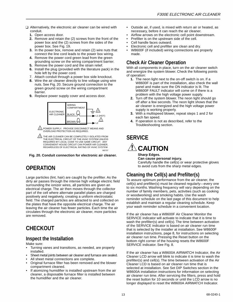
❑ Alternatively, the electronic air cleaner can be wired withconduit.1. Open access door.2. Remove and retain the (2) screws from the front of the
power box and the (2) screws from the sides of thepower box. See Fig. 19.
3. In the power box, remove and retain (2) wire nuts thatconnect the line cord leads to the power box wiring.
4. Remove the power cord green lead from the greengrounding screw on the wiring compartment barrier.
5. Remove the power cord and the strain relief.6. Install the plug (provided with the literature pack) in the
hole left by the power cord.7. Attach conduit through a power box side knockout.8. Wire the air cleaner directly to line voltage using wire
nuts. See Fig. 20. Secure ground connection to thegreen ground screw on the wiring compartmentbarrier.
9. Replace power supply cover and access door.
ELECTRONIC AIR CLEANER
WIRING COMPARTMENT
BLACK
BROWN
POWER SUPPLY. PROVIDE DISCONNECT MEANS AND OVERLOAD PROTECTION AS REQUIRED.
THE AIR CLEANER CAN BE COMPLETELY ISOLATED FROM THE ELECTRICAL CIRCUIT OF THE HVAC SYSTEM UNLESS REQUIRED BY LOCAL CODE TO USE SAME CIRCUIT. ANYCONVENIENT HOUSE CIRCUIT CAN POWER AIR CLEANER, REGARDLESS OF ELECTRICAL RATING OF HVAC SYSTEM.
M5707
2
1
2
L1 (HOT)
L21
Fig. 20. Conduit connection for electronic air cleaner.
OPERATIONLarge particles (lint, hair) are caught by the prefilter. As thedirty air passes through the intense high voltage electric fieldsurrounding the ionizer wires, all particles are given anelectrical charge. The air then moves through the collectorpart of the cell where alternate parallel plates are chargedpositively and negatively, creating a uniform electrostaticfield. The charged particles are attracted to and collected onthe plates that have the opposite electrical charge. The airleaving the air cleaner has fewer particles. Each time the aircirculates through the electronic air cleaner, more particlesare removed.
CHECKOUT
Inspect the InstallationMake sure:• Turning vanes and transitions, as needed, are properly
installed.• Sheet metal joints between air cleaner and furnace are sealed.• All sheet metal connections are complete.• Original furnace filter has been removed and the blower
compartment cleaned.• If atomizing humidifier is installed upstream from the air
cleaner, a disposable furnace filter is installed betweenthe humidifier and the air cleaner.
F300E ELECTRONIC AIR CLEANER
68-0240-1 14
NOTE: To let the heating or air conditioning systemoperate normally while the cell(s) are beingwashed, simply turn off the air cleaner switch.
Vacuum the prefilter or brush, or soak it in a tub. Do notwash the prefilter in the dishwasher or car wash.
Automatic Dishwasher
CAUTIONBurn Hazard.Can cause personal injury.Allow the cell(s) to cool completely in the dishwasherat the end of the wash cycle or wear protectivegloves to avoid burns. Hot water can accumulate inthe tubes supporting the collector plates. Tip thecell(s) so these tubes will drain.
Record wash times on the chart on last page.
IMPORTANT• Check the dishwasher owner’s manual. Some
manufacturers do not recommend washingelectronic cell(s) in their dishwashers.
• If the dishwasher has upper and lower arms,position the cell(s) carefully to allow good watercirculation.
• Be careful to avoid damaging the cell(s) whenplacing them in the dishwasher. Broken ionizerwires or bent collector plates are not included in thewarranty.
• Very dirty cell(s), especially from tobacco orcooking smoke, can discolor the plastic parts andthe lining of some dishwashers. This discoloration isnot harmful. To minimize it, wash the cell(s) morefrequently or try a different brand of detergent.
• Do not allow the dishwasher to run through thedry cycle. This will bake on any contaminants notremoved during the wash cycle and reduce aircleaner efficiency.
1. Put the cell(s) on the lower rack of the dishwasher withthe airflow arrow pointing up. It may be necessary toremove the upper rack. Do not block water flow to theupper arm.
HINT: Lay a few large water glasses between thespikes on the lower rack and rest the cell(s)on them so the spikes do not damage thealuminum collector blades.
2. Using regular dishwashing detergent, allow thedishwasher to run through the complete wash andrinse cycle. Do not use the dry cycle. To avoid burns,let the cell(s) cool completely before removing, or wearprotective gloves when removing the cell(s).Remember that water may be trapped inside thecell(s). Tip the cell(s) so the tubes can drain.
3. Wipe the ionizer wires and contact board on the end ofthe cell using thumb and forefinger with a small, dampcloth.
4. Inspect the dishwasher. Rerun the wash and/or rinsecycle with the dishwasher empty if there is dirt orresidue from washing the cell(s). If dirt or residueseems excessive, wash the cell(s) more often or try adifferent detergent.
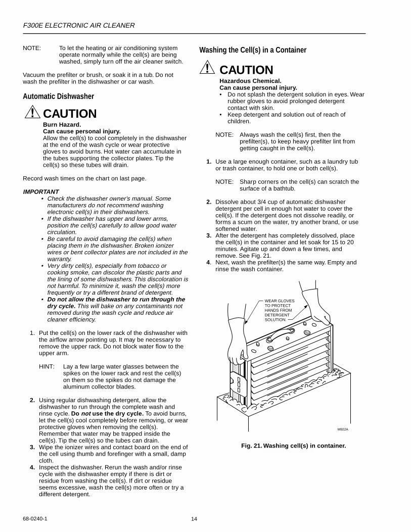
Washing the Cell(s) in a Container
CAUTIONHazardous Chemical.Can cause personal injury.• Do not splash the detergent solution in eyes. Wear
rubber gloves to avoid prolonged detergentcontact with skin.
• Keep detergent and solution out of reach ofchildren.
NOTE: Always wash the cell(s) first, then theprefilter(s), to keep heavy prefilter lint fromgetting caught in the cell(s).
1. Use a large enough container, such as a laundry tubor trash container, to hold one or both cell(s).
NOTE: Sharp corners on the cell(s) can scratch thesurface of a bathtub.
2. Dissolve about 3/4 cup of automatic dishwasherdetergent per cell in enough hot water to cover thecell(s). If the detergent does not dissolve readily, orforms a scum on the water, try another brand, or usesoftened water.
3. After the detergent has completely dissolved, placethe cell(s) in the container and let soak for 15 to 20minutes. Agitate up and down a few times, andremove. See Fig. 21.
4. Next, wash the prefilter(s) the same way. Empty andrinse the wash container.
Fig. 21. Washing cell(s) in container.
M922A
WEAR GLOVESTO PROTECTHANDS FROMDETERGENTSOLUTION.
F300E ELECTRONIC AIR CLEANER
68-0240-115
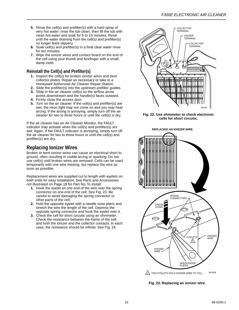
Fig. 23. Replacing an ionizer wire.
COLLECTORTERMINAL
COLLECTORTERMINAL
IONIZERTERMINAL
M6155
5. Rinse the cell(s) and prefilter(s) with a hard spray ofvery hot water; rinse the tub clean, then fill the tub withclean hot water and soak for 5 to 15 minutes. Rinseuntil the water draining from the cell(s) and prefilter(s)no longer feels slippery.
6. Soak cell(s) and prefilter(s) in a final clear water rinsefor ten minutes.
7. Wipe the ionizer wires and contact board on the end ofthe cell using your thumb and forefinger with a small,damp cloth.
Reinstall the Cell(s) and Prefilter(s)1. Inspect the cell(s) for broken ionizer wires and bent
collector plates. Repair as necessary or take to aHoneywell Authorized Air Cleaner Repair Station.
2. Slide the prefilter(s) into the upstream prefilter guides.3. Slide in the air cleaner cell(s) so the airflow arrow
points downstream and the handle(s) faces outward.4. Firmly close the access door.5. Turn on the air cleaner. If the cell(s) and prefilter(s) are
wet, the neon light may not come on and you may heararcing. If the arcing is annoying, simply turn off the aircleaner for two to three hours or until the cell(s) is dry.
If the air cleaner has an Air Cleaner Monitor, the FAULTindicator may activate when the cell(s) and prefilter(s) arewet. Again, if the FAULT indicator is annoying, simply turn offthe air cleaner for two to three hours or until the cell(s) andprefilter(s) are dry.
Replacing Ionizer WiresBroken or bent ionizer wires can cause an electrical short toground, often resulting in visible arcing or sparking. Do notuse cell(s) until broken wires are removed. Cells can be usedtemporarily with one wire missing, but replace the wire assoon as possible.
Replacement wires are supplied cut to length with eyelets onboth ends for easy installation. See Parts and Accessoriesnot illustrated on Page 18 for Part No. To install:
1. Hook the eyelet on one end of the wire over the springconnector on one end of the cell. See Fig. 23. Becareful to avoid damaging the spring connector orother parts of the cell.
2. Hold the opposite eyelet with a needle nose pliers andstretch the wire the length of the cell. Depress theopposite spring connector and hook the eyelet over it.
3. Check the cell for short circuits using an ohmmeter.Check the resistance between the frame of the celland both the ionizer and the collector contacts. In eachcase, the resistance should be infinite. See Fig. 24.
Fig. 22. Use ohmmeter to check electroniccells for short circuits.
M1540B
IONIZERWIRE
IONIZERWIRE
NEEDLENOSEPLIERS
SPRING CONNECTORS
PRESS DOWN
EYELETS
REPLACING AN IONIZER WIRE.
TWO EYELETS HOLD IONIZER WIRE TO CELL.
1
1
F300E ELECTRONIC AIR CLEANER
68-0240-1 16
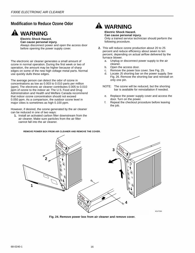
Modification to Reduce Ozone Odor
WARNINGElectric Shock Hazard.Can cause personal injury.Always disconnect power and open the access doorbefore opening the power supply cover.
The electronic air cleaner generates a small amount ofozone in normal operation. During the first week or two ofoperation, the amount may be higher because of sharpedges on some of the new high voltage metal parts. Normaluse quickly dulls these edges.
The average person can detect the odor of ozone inconcentrations as low as 0.003 to 0.010 parts per million(ppm). The electronic air cleaner contributes 0.005 to 0.010ppm of ozone to the indoor air. The U.S. Food and DrugAdministration and Health and Welfare Canada recommendthat indoor ozone concentration should not exceed0.050 ppm. As a comparison, the outdoor ozone level inmajor cities is sometimes as high 0.100 ppm.
However, if desired, the ozone generated by the air cleanercan be reduced in one of two ways:
1. Install an activated carbon filter downstream from theair cleaner. Make sure particles from the air filtercannot fall into the air cleaner.
WARNINGElectric Shock Hazard.Can cause personal injury.Only a trained service technician should perform thefollowing procedure.
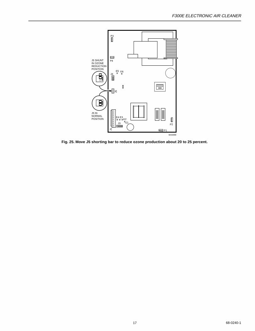
2. This will reduce ozone production about 20 to 25percent and reduce efficiency about seven to tenpercent, depending on actual airflow delivered by thefurnace blower.
a. Unplug or disconnect power supply to the aircleaner.
b. Open the access door.c. Remove the power box cover. See Fig. 25.d. Locate J5 shorting bar on the power supply. See
Fig. 26. Remove the shorting bar and reinstall ononly one pin.
NOTE: The ozone will be reduced, but the shortingbar is available for reinstallation if needed.
e. Replace the power supply cover and access thedoor. Turn on the power.
f. Repeat the checkout procedure before leavingthe job.
4
M14739A
3
1
2
REMOVE POWER BOX FROM AIR CLEANER AND REMOVE THE COVER.
Fig. 24. Remove power box from air cleaner and remove cover.
F300E ELECTRONIC AIR CLEANER
68-0240-117
Fig. 25. Move J5 shorting bar to reduce ozone production about 20 to 25 percent.
P3
P4
P1
P2
M15099
J3
J4
J5 SHUNT IN OZONEREDUCTIONPOSITION
J5 INNORMALPOSITION
J1
J5E4 E3
E1
E5 E6
E2
F300E ELECTRONIC AIR CLEANER
68-0240-1 18
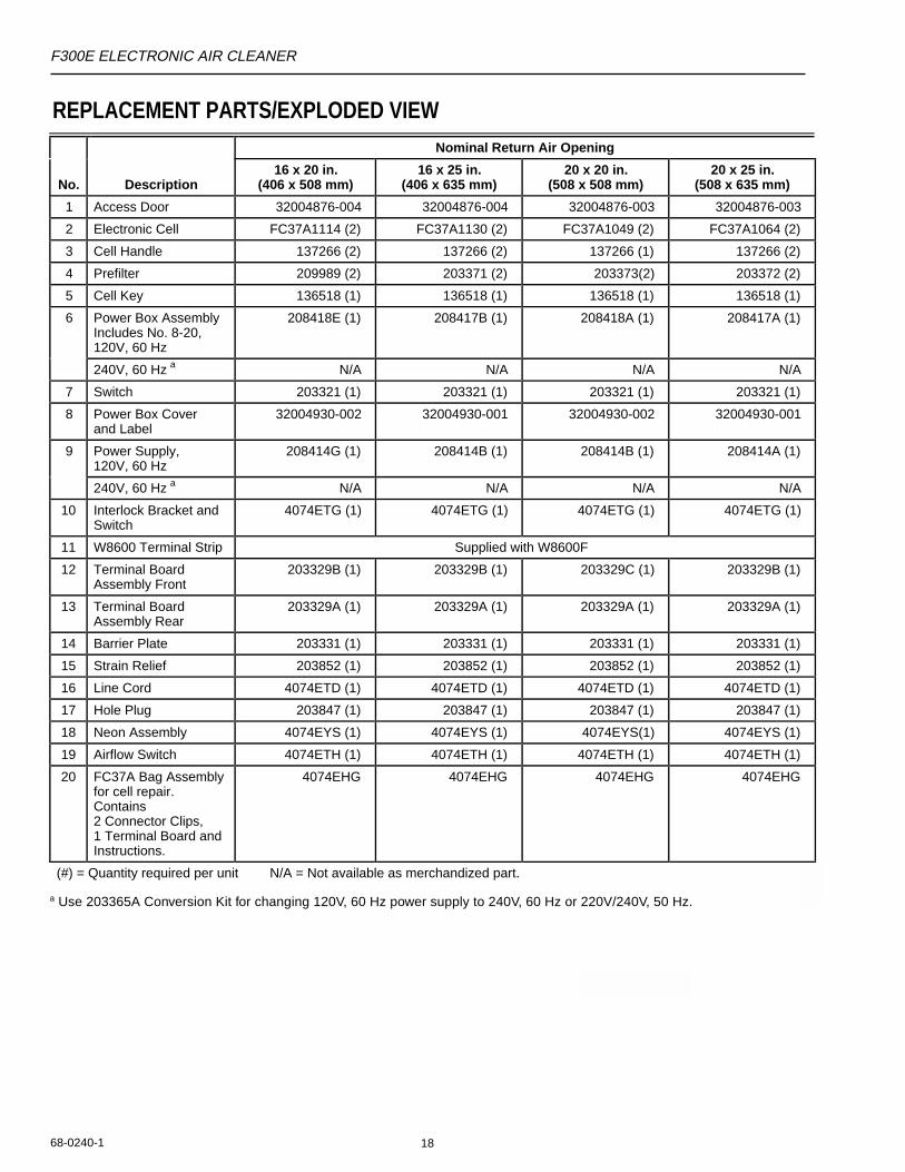
REPLACEMENT PARTS/EXPLODED VIEWNominal Return Air Opening
No. Description16 x 20 in.
(406 x 508 mm)16 x 25 in.
(406 x 635 mm)20 x 20 in.
(508 x 508 mm)20 x 25 in.
(508 x 635 mm)
1 Access Door 32004876-004 32004876-004 32004876-003 32004876-003
2 Electronic Cell FC37A1114 (2) FC37A1130 (2) FC37A1049 (2) FC37A1064 (2)
3 Cell Handle 137266 (2) 137266 (2) 137266 (1) 137266 (2)
4 Prefilter 209989 (2) 203371 (2) 203373(2) 203372 (2)
5 Cell Key 136518 (1) 136518 (1) 136518 (1) 136518 (1)
6 Power Box AssemblyIncludes No. 8-20, 120V, 60 Hz
208418E (1) 208417B (1) 208418A (1) 208417A (1)
240V, 60 Hz N/A N/A N/A N/A
7 Switch 203321 (1) 203321 (1) 203321 (1) 203321 (1)
8 Power Box Cover and Label
32004930-002 32004930-001 32004930-002 32004930-001
9 Power Supply, 120V, 60 Hz
208414G (1) 208414B (1) 208414B (1) 208414A (1)
240V, 60 Hz N/A N/A N/A N/A
10 Interlock Bracket andSwitch
4074ETG (1) 4074ETG (1) 4074ETG (1) 4074ETG (1)
11 W8600 Terminal Strip Supplied with W8600F
12 Terminal Board Assembly Front
203329B (1) 203329B (1) 203329C (1) 203329B (1)
13 Terminal Board Assembly Rear
203329A (1) 203329A (1) 203329A (1) 203329A (1)
14 Barrier Plate 203331 (1) 203331 (1) 203331 (1) 203331 (1)
15 Strain Relief 203852 (1) 203852 (1) 203852 (1) 203852 (1)
16 Line Cord 4074ETD (1) 4074ETD (1) 4074ETD (1) 4074ETD (1)
17 Hole Plug 203847 (1) 203847 (1) 203847 (1) 203847 (1)
18 Neon Assembly 4074EYS (1) 4074EYS (1) 4074EYS(1) 4074EYS (1)
19 Airflow Switch 4074ETH (1) 4074ETH (1) 4074ETH (1) 4074ETH (1)
20 FC37A Bag Assembly for cell repair.Contains 2 Connector Clips, 1 Terminal Board andInstructions.
4074EHG 4074EHG 4074EHG 4074EHG
(#) = Quantity required per unit N/A = Not available as merchandized part.
a Use 203365A Conversion Kit for changing 120V, 60 Hz power supply to 240V, 60 Hz or 220V/240V, 50 Hz.
a
a

F300E ELECTRONIC AIR CLEANER
68-0240-119
Fig. 27. Components of the Electronic Air Cleaner (2-cell model shown).
M147401
2
3
4
5
6
7
8 9
10
11
12
13
14 15
16
17
18
19
20
F300E ELECTRONIC AIR CLEANER
68-0240-1 20
Parts and Accessories Not Illustrated
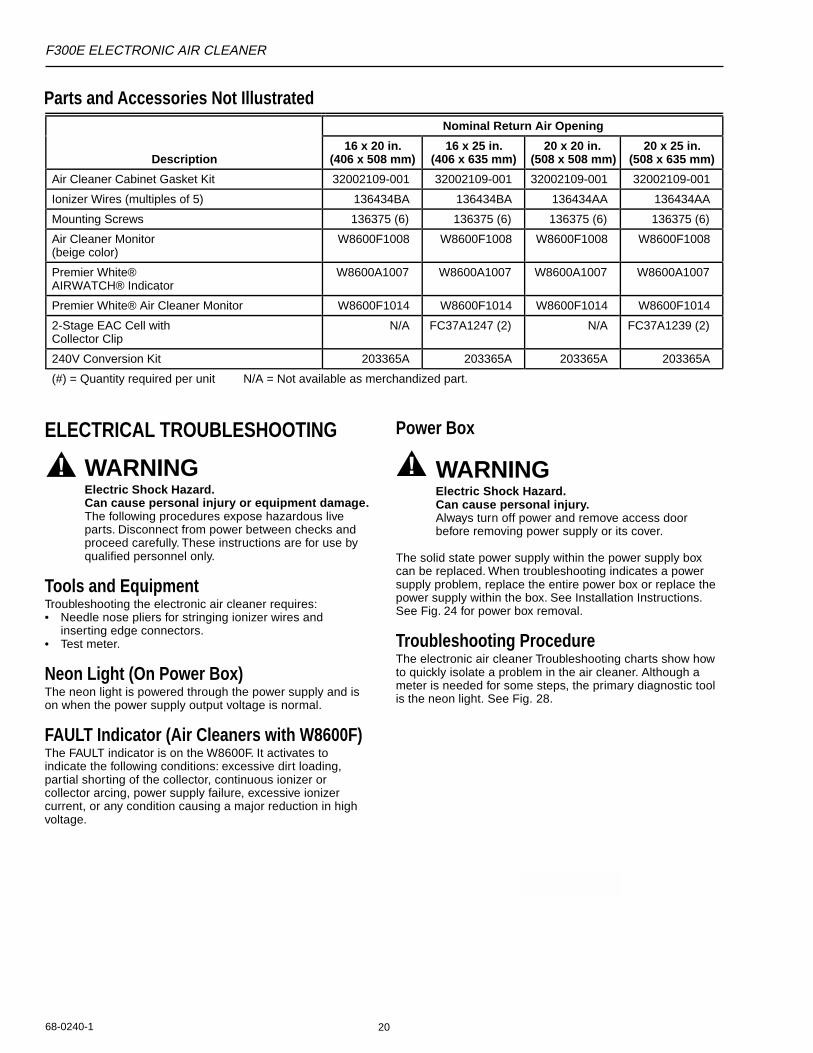
ELECTRICAL TROUBLESHOOTING
WARNINGElectric Shock Hazard.Can cause personal injury or equipment damage.The following procedures expose hazardous liveparts. Disconnect from power between checks andproceed carefully. These instructions are for use byqualified personnel only.
Tools and EquipmentTroubleshooting the electronic air cleaner requires:• Needle nose pliers for stringing ionizer wires and
inserting edge connectors.• Test meter.
Neon Light (On Power Box)The neon light is powered through the power supply and ison when the power supply output voltage is normal.
FAULT Indicator (Air Cleaners with W8600F)The FAULT indicator is on the W8600F. It activates toindicate the following conditions: excessive dirt loading,partial shorting of the collector, continuous ionizer orcollector arcing, power supply failure, excessive ionizercurrent, or any condition causing a major reduction in highvoltage.
Power Box
WARNINGElectric Shock Hazard.Can cause personal injury.Always turn off power and remove access doorbefore removing power supply or its cover.
The solid state power supply within the power supply boxcan be replaced. When troubleshooting indicates a powersupply problem, replace the entire power box or replace thepower supply within the box. See Installation Instructions.See Fig. 24 for power box removal.
Troubleshooting ProcedureThe electronic air cleaner Troubleshooting charts show howto quickly isolate a problem in the air cleaner. Although ameter is needed for some steps, the primary diagnostic toolis the neon light. See Fig. 28.
Nominal Return Air Opening
Description16 x 20 in.
(406 x 508 mm)16 x 25 in.
(406 x 635 mm)20 x 20 in.
(508 x 508 mm)20 x 25 in.
(508 x 635 mm)
Air Cleaner Cabinet Gasket Kit 32002109-001 32002109-001 32002109-001 32002109-001
Ionizer Wires (multiples of 5) 136434BA 136434BA 136434AA 136434AA
Mounting Screws 136375 (6) 136375 (6) 136375 (6) 136375 (6)
Air Cleaner Monitor (beige color)
W8600F1008 W8600F1008 W8600F1008 W8600F1008
Premier White® AIRWATCH® Indicator
W8600A1007 W8600A1007 W8600A1007 W8600A1007
Premier White® Air Cleaner Monitor W8600F1014 W8600F1014 W8600F1014 W8600F1014
2-Stage EAC Cell with Collector Clip
N/A FC37A1247 (2) N/A FC37A1239 (2)
240V Conversion Kit 203365A 203365A 203365A 203365A
(#) = Quantity required per unit N/A = Not available as merchandized part.
F300E ELECTRONIC AIR CLEANER
68-0240-121
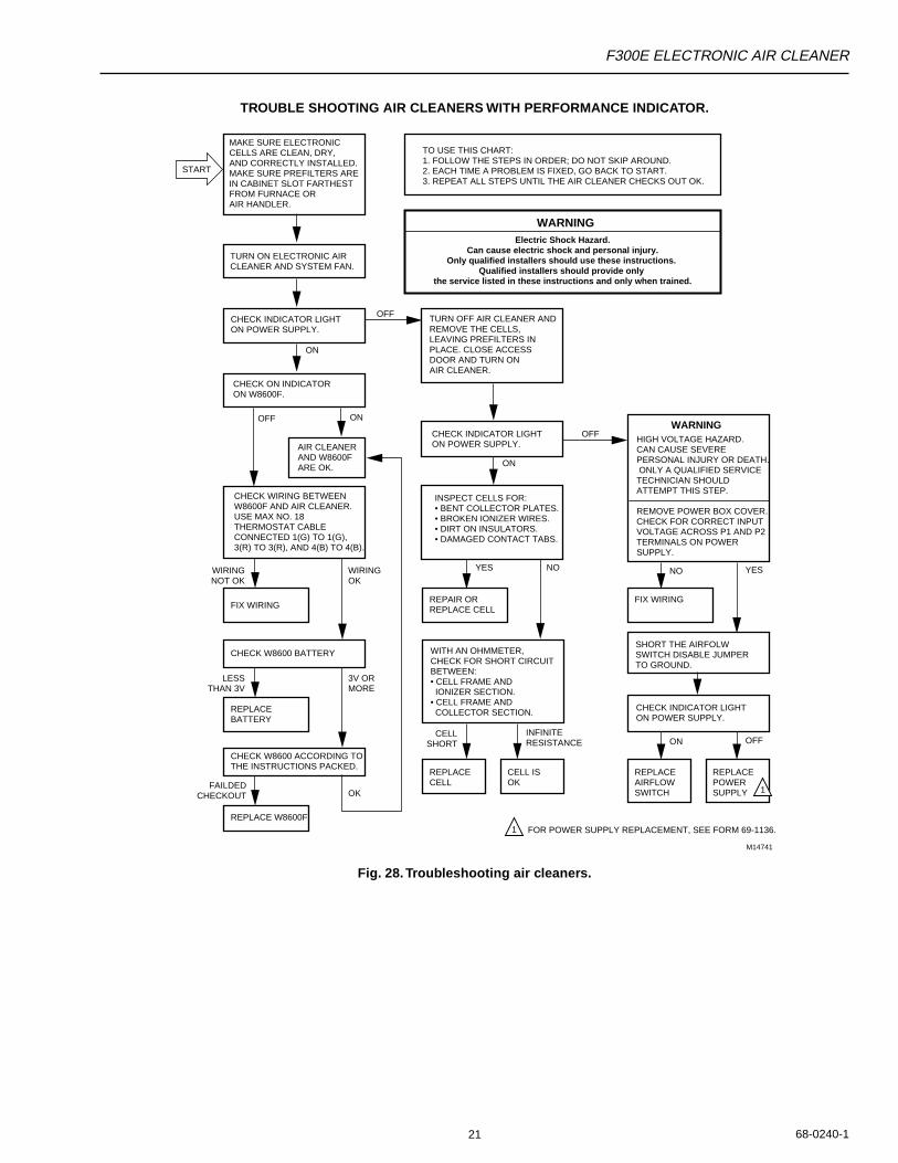
TROUBLE SHOOTING AIR CLEANERS WITH PERFORMANCE INDICATOR.
Fig. 28. Troubleshooting air cleaners.
MAKE SURE ELECTRONIC CELLS ARE CLEAN, DRY, AND CORRECTLY INSTALLED. MAKE SURE PREFILTERS ARE IN CABINET SLOT FARTHEST FROM FURNACE OR AIR HANDLER.
TURN ON ELECTRONIC AIR CLEANER AND SYSTEM FAN.
OFF
START
CHECK INDICATOR LIGHT ON POWER SUPPLY.
CHECK ON INDICATOR ON W8600F.
AIR CLEANERAND W8600F ARE OK.
CHECK WIRING BETWEEN W8600F AND AIR CLEANER.USE MAX NO. 18 THERMOSTAT CABLE CONNECTED 1(G) TO 1(G), 3(R) TO 3(R), AND 4(B) TO 4(B).
CHECK W8600 ACCORDING TO THE INSTRUCTIONS PACKED.
REPLACE W8600F
OK
YES NO
INFINITERESISTANCE
3V ORMORE
WIRINGOK
LESSTHAN 3V
FAILDEDCHECKOUT
CELLSHORT
WIRINGNOT OK
M14741
CHECK W8600 BATTERY
FIX WIRINGREPAIR ORREPLACE CELL
REPLACE CELL
CELL ISOK
REPLACE BATTERY
TURN OFF AIR CLEANER AND REMOVE THE CELLS, LEAVING PREFILTERS IN PLACE. CLOSE ACCESS DOOR AND TURN ONAIR CLEANER.
CHECK INDICATOR LIGHT ON POWER SUPPLY.
INSPECT CELLS FOR:• BENT COLLECTOR PLATES.• BROKEN IONIZER WIRES.• DIRT ON INSULATORS.• DAMAGED CONTACT TABS.
WITH AN OHMMETER,CHECK FOR SHORT CIRCUITBETWEEN:• CELL FRAME AND IONIZER SECTION.• CELL FRAME AND COLLECTOR SECTION.
FIX WIRING
REPLACE AIRFLOWSWITCH
REPLACEPOWERSUPPLY
SHORT THE AIRFOLWSWITCH DISABLE JUMPERTO GROUND.
CHECK INDICATOR LIGHTON POWER SUPPLY.
HIGH VOLTAGE HAZARD.CAN CAUSE SEVERE PERSONAL INJURY OR DEATH. ONLY A QUALIFIED SERVICE TECHNICIAN SHOULD ATTEMPT THIS STEP.
REMOVE POWER BOX COVER. CHECK FOR CORRECT INPUT VOLTAGE ACROSS P1 AND P2TERMINALS ON POWERSUPPLY.
WARNING
WARNINGElectric Shock Hazard.
Can cause electric shock and personal injury.Only qualified installers should use these instructions.
Qualified installers should provide only the service listed in these instructions and only when trained.
TO USE THIS CHART:1. FOLLOW THE STEPS IN ORDER; DO NOT SKIP AROUND.2. EACH TIME A PROBLEM IS FIXED, GO BACK TO START.3. REPEAT ALL STEPS UNTIL THE AIR CLEANER CHECKS OUT OK.
1
1 FOR POWER SUPPLY REPLACEMENT, SEE FORM 69-1136.
ON
ON
OFFON
OFF
ONOFF
YESNO

F300E ELECTRONIC AIR CLEANER
68-0240-1 22
F300E ELECTRONIC AIR CLEANER
68-0240-123
YEAR
ELECTRONIC AIR CLEANER WASH REMINDER SCHEDULE
,
M982A
J F M A M J J A S O N D
INSTALLATION DATE:
Home and Building ControlHoneywell Limited-Honeywell Limitée35 Dynamic DriveScarborough, OntarioM1V 4Z9
68-0240-1 G.H. Rev. 9-00
Home and Building ControlHoneywell1985 Douglas Drive NorthGolden Valley, MN 55422
Printed in U.S.A. on recycled paper containing at least 10% post-consumer paper fibers. www.honeywell.com
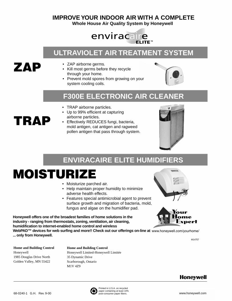
ZAP
TRAP
ULTRAVIOLET AIR TREATMENT SYSTEM
F300E ELECTRONIC AIR CLEANER
ENVIRACAIRE ELITE HUMIDIFIERS
• ZAP airborne germs.• Kill most germs before they recycle
through your home.• Prevent mold spores from growing on your
system cooling coils.
• TRAP airborne particles.• Up to 99% efficient at capturing
airborne particles.• Effectively REDUCES fungi, bacteria,
mold antigen, cat antigen and ragweedpollen antigen that pass through system.
• Moisturize parched air.• Help maintain proper humidity to minimize
adverse health effects.• Features special antimicrobial agent to prevent
surface growth and migration of bacteria, mold, fungus and algae on the humidifier pad.
M14757
Honeywell offers one of the broadest families of home solutions in the industry - ranging from thermostats, zoning, ventilation, air cleaning, humidification to internet-enabled home control and wireless WebPAD™ devices for web surfing and more!! Check out our offerings on-line at... only from Honeywell.
IMPROVE YOUR INDOOR AIR WITH A COMPLETEWhole House Air Quality System by Honeywell


![Electronic National Identity Card Technical Specifications · [DigitalIdentity] National Personalization specification . Ref.: Electronic National Identity Card – Technical Specifications](https://img.pdfslide.us/doc/110x75/60ba36966aecd162863fd1b2/electronic-national-identity-card-technical-specifications-digitalidentity-national.jpg)