Embed Size (px)
Citation preview
F2000EX EASY 02-23-00
CODDE 1 PAGE 1 / 2
DGT94085
ATA 23 – COMMUNICATION TABLE OF CONTENTS
ISSUE 3
DASSAULT AVIATION Proprietary Data
02-23 ATA 23 – COMMUNICATION
02-23-00 TABLE OF CONTENTS
02-23-05 GENERAL
Introduction Sources Communication interface Circuit breakers
02-23-10 VHF RADIO
Introduction VHF tuning Receiving Transmitting Interphone plug jacks Abnormal operations
02-23-15 HF RADIO
HF tuning HF modes Receiving Transmitting
02-23-20 RADIO-NAVIGATION
Introduction NAV (ILS / VOR / DME-VOR / VORTAC and TACAN) ADF ADF modes
02-23-30 CMF/AFIS
Introduction Status/config tab Winds tab Tem Wx tab Sigmet tab Rx Msg tab Tx Msg tab
02-23-00 F2000EX EASY
PAGE 2 / 2 CODDE 1
ISSUE 3
ATA 23 – COMMUNICATION TABLE OF CONTENTS
DGT94085
DASSAULT AVIATION Proprietary Data
02-23-35 ABNORMAL OPERATION
CAS messages
F2000EX EASY 02-23-05
CODDE 1 PAGE 1 / 12
DGT94085
ATA 23 – COMMUNICATION GENERAL
ISSUE 3
DASSAULT AVIATION Proprietary Data
INTRODUCTION
The present relates to radio-communications (VHF, HF), radio-navigation (NAV, ADF, DME) and CMF/AFIS (optional).
For ATC/TCAS, refer to CODDE1 / Chapter 02 / ATA 34 - 70 - Surveillance
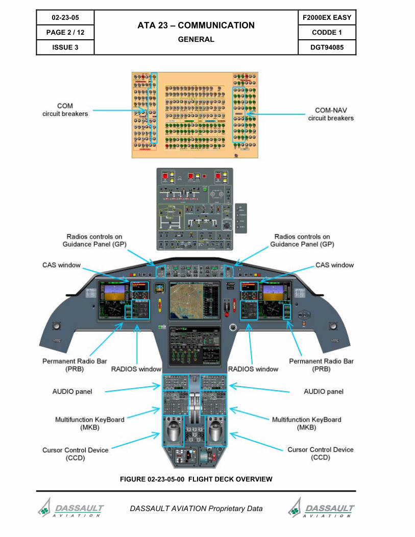
The communication system management can be done through controls located on the Guidance Panel (GP), the Cursor Control Device (CCD), the Multifunction Keyboard (MKB) and the AUDIO panel.
Radio indications are displayed on both Primary Display Units (PDU) in two dedicated areas, the Permanent Radio Bar (PRB) in the lower right hand corner of the Horizontal Situation Indicator (HSI), and the RADIOS page which appears on request in the 1/6 lower of the PDU.
CMF/AFIS is displayed on the either Multifunction Display Unit (MDU) in the 1/3 window. Only one CMF/AFIS window is allowed in a MDU at a time.
The F2000EX EASy basically features two independent sets of equipment:
- Set 1 including VHF 1, HF 1, NAV 1, DME 1, ADF 1, ATC 1,
- Set 2 including VHF 2, HF 2, NAV 2, DME 2, ADF 2, ATC 2.
02-23-05 F2000EX EASY
PAGE 2 / 12 CODDE 1
ISSUE 3
ATA 23 – COMMUNICATION GENERAL
DGT94085
DASSAULT AVIATION Proprietary Data
FIGURE 02-23-05-00 FLIGHT DECK OVERVIEW
F2000EX EASY 02-23-05
CODDE 1 PAGE 3 / 12
DGT94085
ATA 23 – COMMUNICATION GENERAL
ISSUE 3
DASSAULT AVIATION Proprietary Data
SOURCES
ELECTRICAL SOURCES
The radio system is fed by a 28V / 25A DC source through four buses: set 1 is powered through buses A1 and A2 and set 2 is powered through buses B1 and B2. The AUDIO panels are powered through bus A2 for the left hand and the third crew member AUDIO PANEL, and through bus B2 for the right hand AUDIO PANEL. Operations on mini-load provide full functionality of the entire radio Set 1, VHF 2 and HF 2.
For more information, refer to CODDE 1 / Chapter 02 / ATA 24.
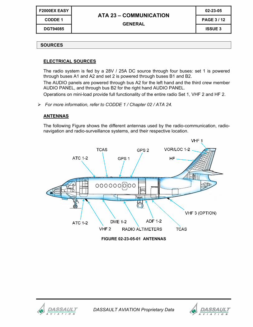
ANTENNAS
The following Figure shows the different antennas used by the radio-communication, radio-navigation and radio-surveillance systems, and their respective location.
FIGURE 02-23-05-01 ANTENNAS
02-23-05 F2000EX EASY
PAGE 4 / 12 CODDE 1
ISSUE 3
ATA 23 – COMMUNICATION GENERAL
DGT94085
DASSAULT AVIATION Proprietary Data
COMMUNICATION INTERFACE
PERMANENT RADIO BAR
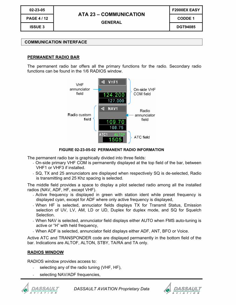
The permanent radio bar offers all the primary functions for the radio. Secondary radio functions can be found in the 1/6 RADIOS window.
Radioannunciator
field
VHFannunciator
field
FIGURE 02-23-05-02 PERMANENT RADIO INFORMATION
The permanent radio bar is graphically divided into three fields: - On-side primary VHF COM is permanently displayed at the top field of the bar, between
VHF1 or VHF3 if installed. - SQ, TX and 25 annunciators are displayed when respectively SQ is de-selected, Radio
is transmitting and 25 Khz spacing is selected. The middle field provides a space to display a pilot selected radio among all the installed radios (NAV, ADF, HF, except VHF).
- Active frequency is displayed in green with station ident while preset frequency is displayed cyan, except for ADF where only active frequency is displayed,
- When HF is selected, annuciator fields displays TX for Transmit Status, Emission selection of UV, LV, AM, LD or UD, Duplex for duplex mode, and SQ for Squelch Selection.
- When NAV is selected, annunciator field displays either AUTO when FMS auto-tuning is active or “H” with held frequency,
- When ADF is selected, annunciator field displays either ADF, ANT, BFO or Voice. Active ATC and TRANSPONDER code are displayed permanently in the bottom field of the bar. Indications are ALTOF, ALTON, STBY, TA/RA and TA only.
RADIOS WINDOW
RADIOS window provides access to: - selecting any of the radio tuning (VHF, HF),
- selecting NAV/ADF frequencies,
F2000EX EASY 02-23-05
CODDE 1 PAGE 5 / 12
DGT94085
ATA 23 – COMMUNICATION GENERAL
ISSUE 3
DASSAULT AVIATION Proprietary Data
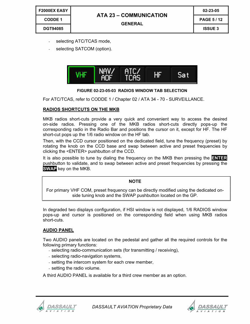
- selecting ATC/TCAS mode,
- selecting SATCOM (option).
FIGURE 02-23-05-03 RADIOS WINDOW TAB SELECTION
For ATC/TCAS, refer to CODDE 1 / Chapter 02 / ATA 34 - 70 - SURVEILLANCE.
RADIOS SHORTCUTS ON THE MKB
MKB radios short-cuts provide a very quick and convenient way to access the desired on-side radios. Pressing one of the MKB radios short-cuts directly pops-up the corresponding radio in the Radio Bar and positions the cursor on it, except for HF. The HF short-cut pops up the 1/6 radio window on the HF tab. Then, with the CCD cursor positioned on the dedicated field, tune the frequency (preset) by rotating the knob on the CCD base and swap between active and preset frequencies by clicking the <ENTER> pushbutton of the CCD. It is also possible to tune by dialing the frequency on the MKB then pressing the ENTER pushbutton to validate, and to swap between active and preset frequencies by pressing the SWAP key on the MKB.
NOTE
For primary VHF COM, preset frequency can be directly modified using the dedicated on-side tuning knob and the SWAP pushbutton located on the GP.
In degraded two displays configuration, if HSI window is not displayed, 1/6 RADIOS window pops-up and cursor is positioned on the corresponding field when using MKB radios short-cuts.
AUDIO PANEL
Two AUDIO panels are located on the pedestal and gather all the required controls for the following primary functions:
- selecting radio-communication sets (for transmitting / receiving), - selecting radio-navigation systems, - setting the intercom system for each crew member, - setting the radio volume.
A third AUDIO PANEL is available for a third crew member as an option.
02-23-05 F2000EX EASY
PAGE 6 / 12 CODDE 1
ISSUE 3
ATA 23 – COMMUNICATION GENERAL
DGT94085
DASSAULT AVIATION Proprietary Data
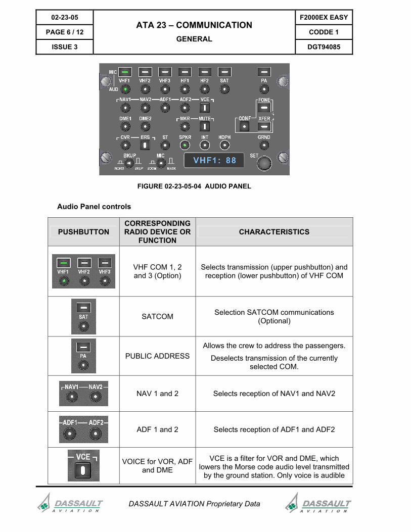
FIGURE 02-23-05-04 AUDIO PANEL
Audio Panel controls
PUSHBUTTON CORRESPONDING RADIO DEVICE OR
FUNCTION CHARACTERISTICS
VHF COM 1, 2 and 3 (Option)
Selects transmission (upper pushbutton) and reception (lower pushbutton) of VHF COM
SATCOM Selection SATCOM communications (Optional)
PUBLIC ADDRESS Allows the crew to address the passengers.
Deselects transmission of the currently selected COM.
NAV 1 and 2 Selects reception of NAV1 and NAV2
ADF 1 and 2 Selects reception of ADF1 and ADF2
VOICE for VOR, ADF and DME
VCE is a filter for VOR and DME, which lowers the Morse code audio level transmitted
by the ground station. Only voice is audible
F2000EX EASY 02-23-05
CODDE 1 PAGE 7 / 12
DGT94085
ATA 23 – COMMUNICATION GENERAL
ISSUE 3
DASSAULT AVIATION Proprietary Data
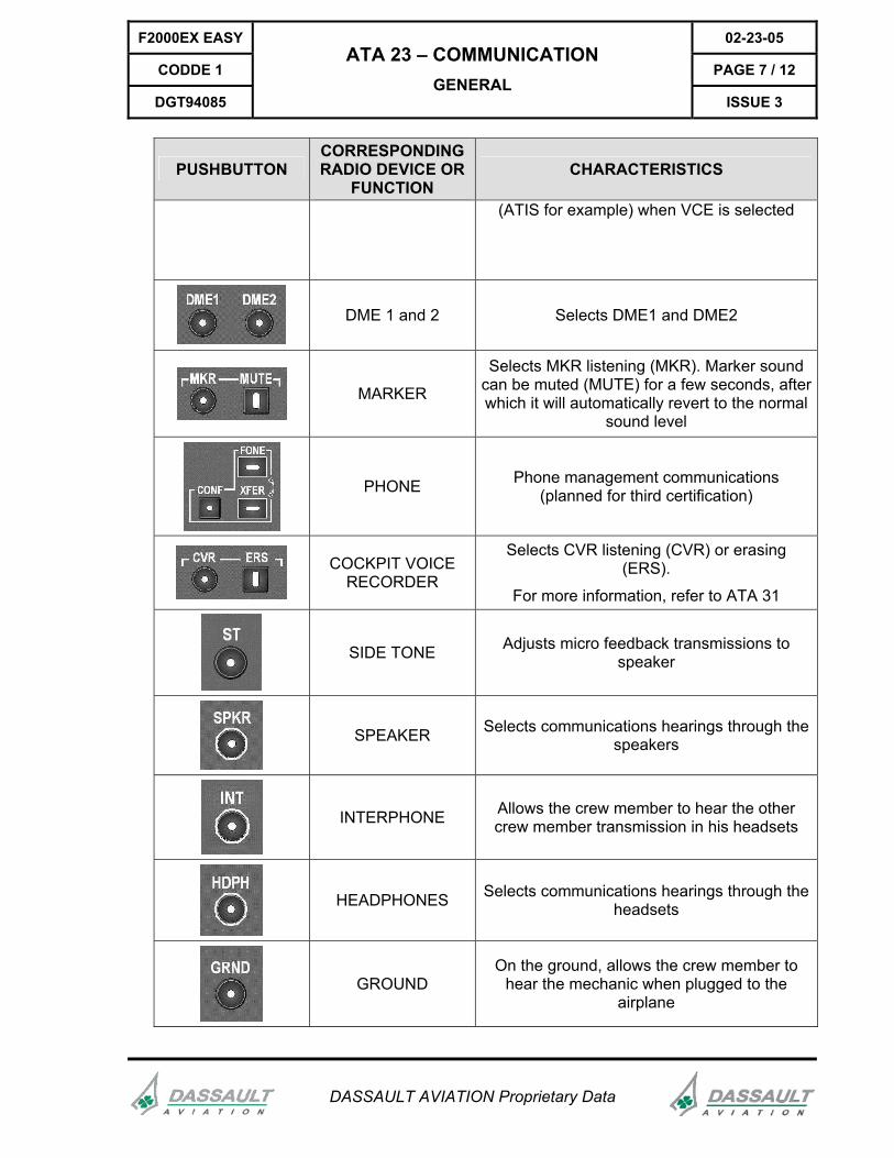
PUSHBUTTON CORRESPONDING RADIO DEVICE OR
FUNCTION CHARACTERISTICS
(ATIS for example) when VCE is selected
DME 1 and 2 Selects DME1 and DME2
MARKER
Selects MKR listening (MKR). Marker sound can be muted (MUTE) for a few seconds, after which it will automatically revert to the normal
sound level
PHONE Phone management communications (planned for third certification)
COCKPIT VOICE RECORDER
Selects CVR listening (CVR) or erasing (ERS).
For more information, refer to ATA 31
SIDE TONE Adjusts micro feedback transmissions to speaker
SPEAKER Selects communications hearings through the speakers
INTERPHONE Allows the crew member to hear the other crew member transmission in his headsets
HEADPHONES Selects communications hearings through the headsets
GROUND On the ground, allows the crew member to
hear the mechanic when plugged to the airplane
02-23-05 F2000EX EASY
PAGE 8 / 12 CODDE 1
ISSUE 3
ATA 23 – COMMUNICATION GENERAL
DGT94085
DASSAULT AVIATION Proprietary Data
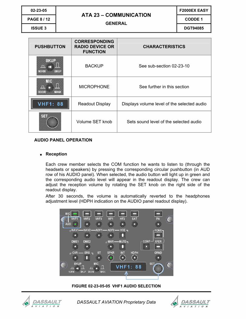
PUSHBUTTON CORRESPONDING RADIO DEVICE OR
FUNCTION CHARACTERISTICS
BACKUP See sub-section 02-23-10
MICROPHONE See further in this section
Readout Display Displays volume level of the selected audio
Volume SET knob Sets sound level of the selected audio
AUDIO PANEL OPERATION
■ Reception
Each crew member selects the COM function he wants to listen to (through the headsets or speakers) by pressing the corresponding circular pushbutton (in AUD row of his AUDIO panel). When selected, the audio button will light up in green and the corresponding audio level will appear in the readout display. The crew can adjust the reception volume by rotating the SET knob on the right side of the readout display. After 30 seconds, the volume is automatically reverted to the headphones adjustment level (HDPH indication on the AUDIO panel readout display).
FIGURE 02-23-05-05 VHF1 AUDIO SELECTION
F2000EX EASY 02-23-05
CODDE 1 PAGE 9 / 12
DGT94085
ATA 23 – COMMUNICATION GENERAL
ISSUE 3
DASSAULT AVIATION Proprietary Data
All the COM devices audio reception can be selected simulltaneously. To deselect one of them, press again on the associated AUD pushbutton.
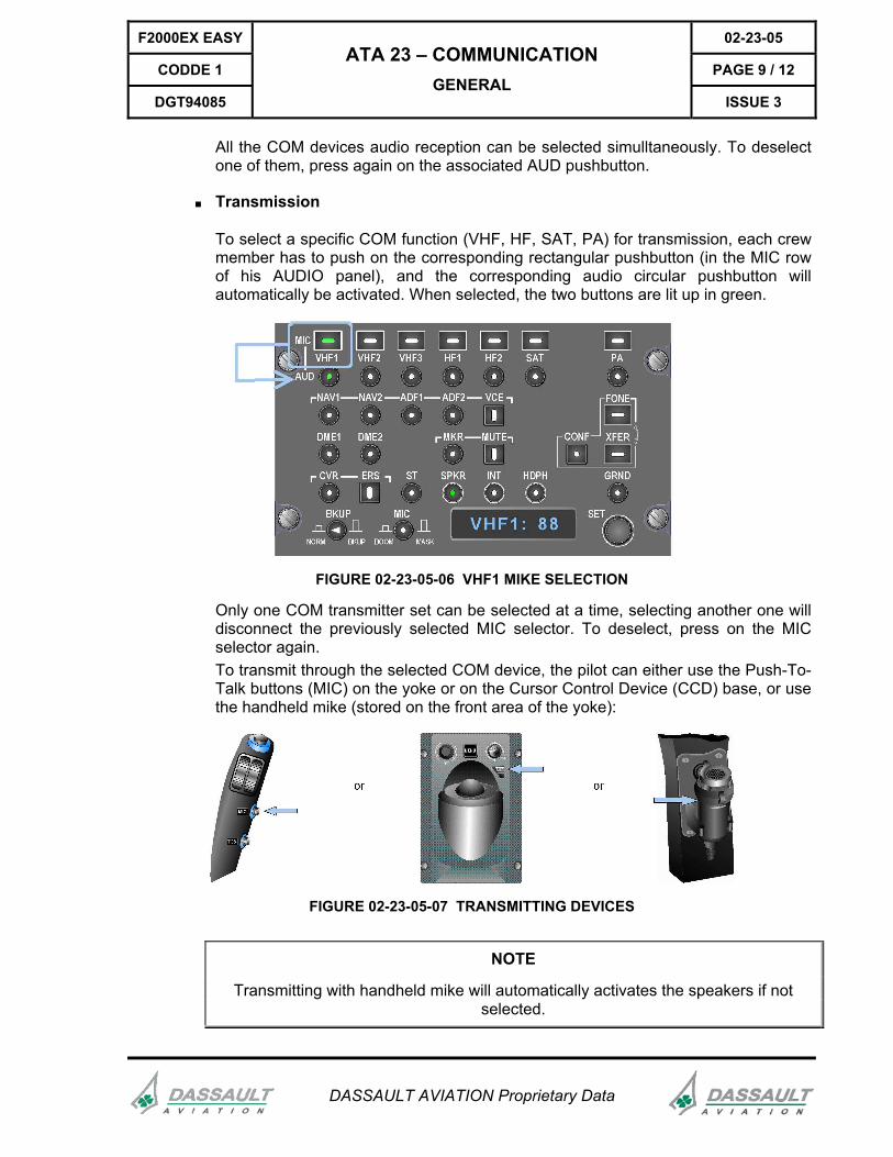
■ Transmission
To select a specific COM function (VHF, HF, SAT, PA) for transmission, each crew member has to push on the corresponding rectangular pushbutton (in the MIC row of his AUDIO panel), and the corresponding audio circular pushbutton will automatically be activated. When selected, the two buttons are lit up in green.
FIGURE 02-23-05-06 VHF1 MIKE SELECTION
Only one COM transmitter set can be selected at a time, selecting another one will disconnect the previously selected MIC selector. To deselect, press on the MIC selector again. To transmit through the selected COM device, the pilot can either use the Push-To-Talk buttons (MIC) on the yoke or on the Cursor Control Device (CCD) base, or use the handheld mike (stored on the front area of the yoke):
FIGURE 02-23-05-07 TRANSMITTING DEVICES
NOTE
Transmitting with handheld mike will automatically activates the speakers if not selected.
02-23-05 F2000EX EASY
PAGE 10 / 12 CODDE 1
ISSUE 3
ATA 23 – COMMUNICATION GENERAL
DGT94085
DASSAULT AVIATION Proprietary Data
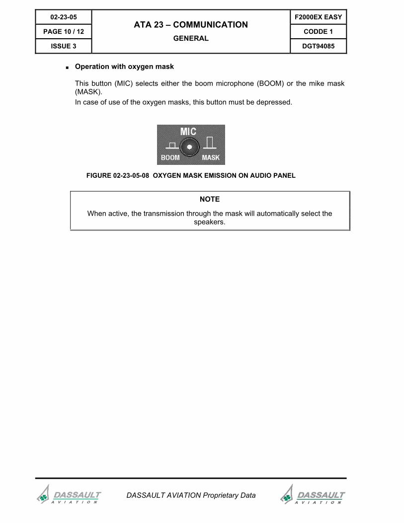
■ Operation with oxygen mask
This button (MIC) selects either the boom microphone (BOOM) or the mike mask (MASK). In case of use of the oxygen masks, this button must be depressed.
FIGURE 02-23-05-08 OXYGEN MASK EMISSION ON AUDIO PANEL
NOTE
When active, the transmission through the mask will automatically select the speakers.
F2000EX EASY 02-23-05
CODDE 1 PAGE 11 / 12
DGT94085
ATA 23 – COMMUNICATION GENERAL
ISSUE 3
DASSAULT AVIATION Proprietary Data
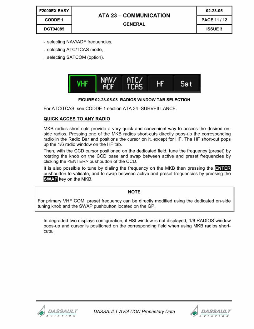
- selecting NAV/ADF frequencies,
- selecting ATC/TCAS mode,
- selecting SATCOM (option).
FIGURE 02-23-05-08 RADIOS WINDOW TAB SELECTION
For ATC/TCAS, see CODDE 1 section ATA 34 -SURVEILLANCE.
QUICK ACCES TO ANY RADIO
MKB radios short-cuts provide a very quick and convenient way to access the desired on-side radios. Pressing one of the MKB radios short-cuts directly pops-up the corresponding radio in the Radio Bar and positions the cursor on it, except for HF. The HF short-cut pops up the 1/6 radio window on the HF tab. Then, with the CCD cursor positioned on the dedicated field, tune the frequency (preset) by rotating the knob on the CCD base and swap between active and preset frequencies by clicking the <ENTER> pushbutton of the CCD. It is also possible to tune by dialing the frequency on the MKB then pressing the ENTER pushbutton to validate, and to swap between active and preset frequencies by pressing the SWAP key on the MKB.
NOTE
For primary VHF COM, preset frequency can be directly modified using the dedicated on-side tuning knob and the SWAP pushbutton located on the GP.
In degraded two displays configuration, if HSI window is not displayed, 1/6 RADIOS window pops-up and cursor is positioned on the corresponding field when using MKB radios short-cuts.
02-23-05 F2000EX EASY
PAGE 12 / 12 CODDE 1
ISSUE 3
ATA 23 – COMMUNICATION GENERAL
DGT94085
DASSAULT AVIATION Proprietary Data
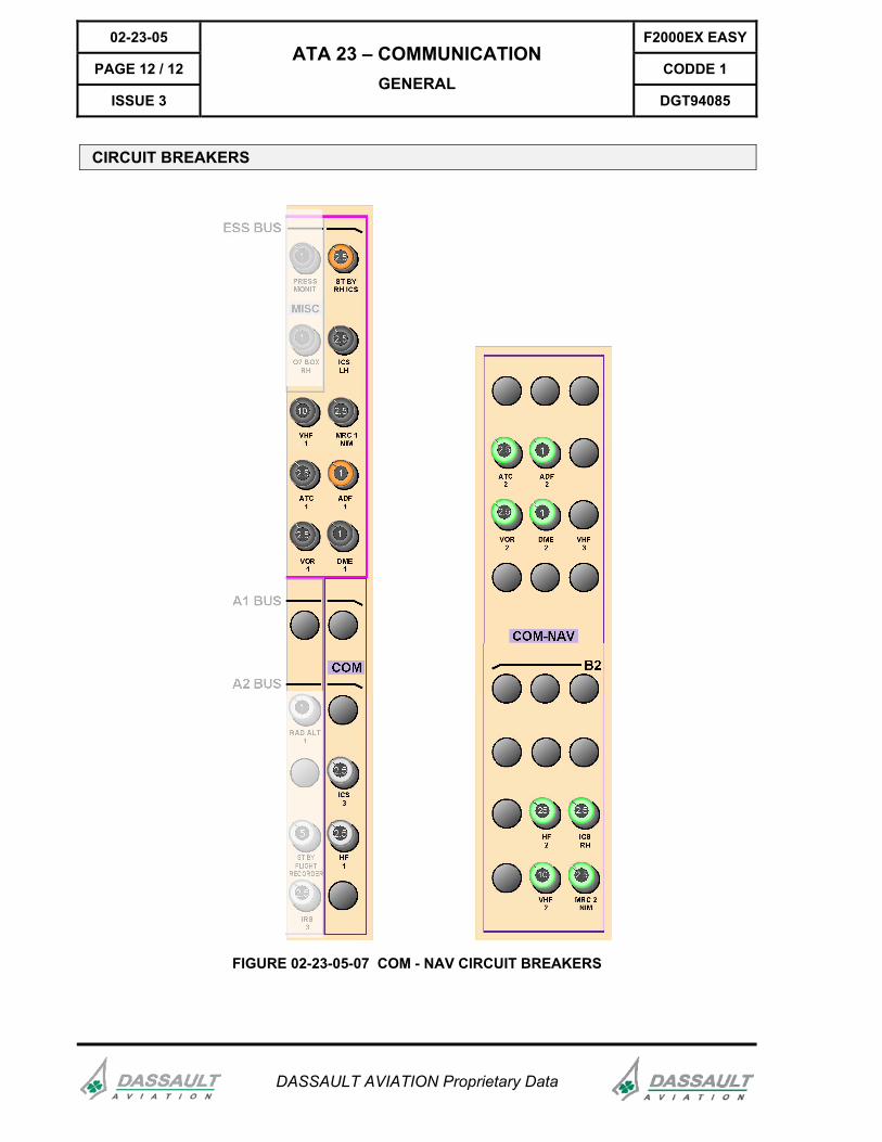
CIRCUIT BREAKERS
FIGURE 02-23-05-07 COM - NAV CIRCUIT BREAKERS
F2000EX EASY 02-23-10
CODDE 1 PAGE 1 / 12
DGT94085
ATA 23 – COMMUNICATION VHF RADIO
ISSUE 3
DASSAULT AVIATION Proprietary Data
INTRODUCTION
The VHF1, VHF2 and VHF3 (optional) are set and tuned by using one of the three sets of controls located on the Guidance Panel (GP), the Cursor Control Device (CCD) and the Multifunction KeyBoard (MKB).
VHF spacing can be set to 25 kHz or 8.33 kHz.
The VHF3 is a third VHF COM, usable for voice communication and for datalink (optional).
VHF TUNING
TUNING THROUGH THE GUIDANCE PANEL (GP)
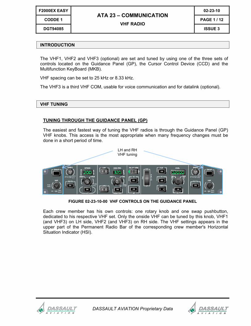
The easiest and fastest way of tuning the VHF radios is through the Guidance Panel (GP) VHF knobs. This access is the most appropriate when many frequency changes must be done in a short period of time.
LH and RHVHF tuning
FIGURE 02-23-10-00 VHF CONTROLS ON THE GUIDANCE PANEL
Each crew member has his own controls: one rotary knob and one swap pushbutton, dedicated to his respective VHF set. Only the onside VHF can be tuned by this knob, VHF1 (and VHF3) on LH side, VHF2 (and VHF3) on RH side. The VHF settings appears in the upper part of the Permanent Radio Bar of the corresponding crew member's Horizontal Situation Indicator (HSI).
02-23-10 F2000EX EASY
PAGE 2 / 12 CODDE 1
ISSUE 3
ATA 23 – COMMUNICATION VHF RADIO
DGT94085
DASSAULT AVIATION Proprietary Data
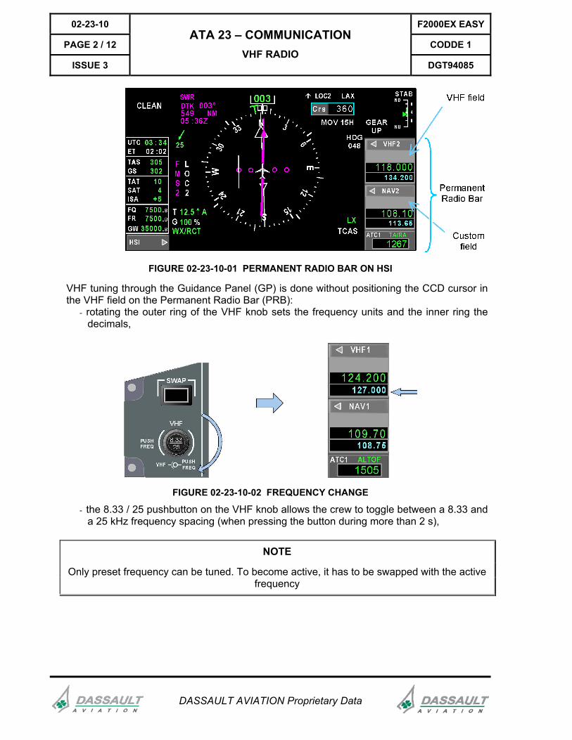
FIGURE 02-23-10-01 PERMANENT RADIO BAR ON HSI
VHF tuning through the Guidance Panel (GP) is done without positioning the CCD cursor in the VHF field on the Permanent Radio Bar (PRB):
- rotating the outer ring of the VHF knob sets the frequency units and the inner ring the decimals,
FIGURE 02-23-10-02 FREQUENCY CHANGE
- the 8.33 / 25 pushbutton on the VHF knob allows the crew to toggle between a 8.33 and a 25 kHz frequency spacing (when pressing the button during more than 2 s),
NOTE
Only preset frequency can be tuned. To become active, it has to be swapped with the active frequency
F2000EX EASY 02-23-10
CODDE 1 PAGE 3 / 12
DGT94085
ATA 23 – COMMUNICATION VHF RADIO
ISSUE 3
DASSAULT AVIATION Proprietary Data
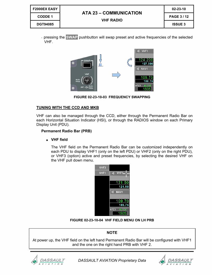
- pressing the SWAP pushbutton will swap preset and active frequencies of the selected VHF.
FIGURE 02-23-10-03 FREQUENCY SWAPPING
TUNING WITH THE CCD AND MKB
VHF can also be managed through the CCD, either through the Permanent Radio Bar on each Horizontal Situation Indicator (HSI), or through the RADIOS window on each Primary Display Unit (PDU).
Permanent Radio Bar (PRB)
■ VHF field
The VHF field on the Permanent Radio Bar can be customized independently on each PDU to display VHF1 (only on the left PDU) or VHF2 (only on the right PDU), or VHF3 (option) active and preset frequencies, by selecting the desired VHF on the VHF pull down menu.
FIGURE 02-23-10-04 VHF FIELD MENU ON LH PRB
NOTE
At power up, the VHF field on the left hand Permanent Radio Bar will be configured with VHF1 and the one on the right hand PRB with VHF 2.
02-23-10 F2000EX EASY
PAGE 4 / 12 CODDE 1
ISSUE 3
ATA 23 – COMMUNICATION VHF RADIO
DGT94085
DASSAULT AVIATION Proprietary Data
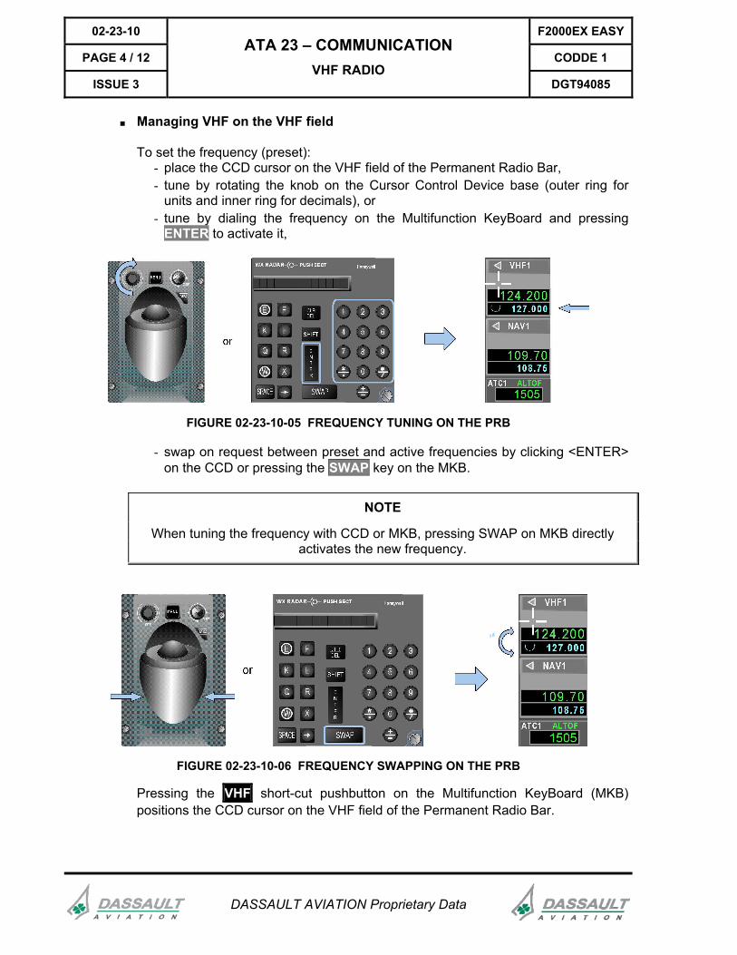
■ Managing VHF on the VHF field
To set the frequency (preset): - place the CCD cursor on the VHF field of the Permanent Radio Bar, - tune by rotating the knob on the Cursor Control Device base (outer ring for
units and inner ring for decimals), or - tune by dialing the frequency on the Multifunction KeyBoard and pressing
ENTER to activate it,
FIGURE 02-23-10-05 FREQUENCY TUNING ON THE PRB
- swap on request between preset and active frequencies by clicking <ENTER> on the CCD or pressing the SWAP key on the MKB.
NOTE
When tuning the frequency with CCD or MKB, pressing SWAP on MKB directly activates the new frequency.
FIGURE 02-23-10-06 FREQUENCY SWAPPING ON THE PRB
Pressing the VHF short-cut pushbutton on the Multifunction KeyBoard (MKB) positions the CCD cursor on the VHF field of the Permanent Radio Bar.
F2000EX EASY 02-23-10
CODDE 1 PAGE 5 / 12
DGT94085
ATA 23 – COMMUNICATION VHF RADIO
ISSUE 3
DASSAULT AVIATION Proprietary Data
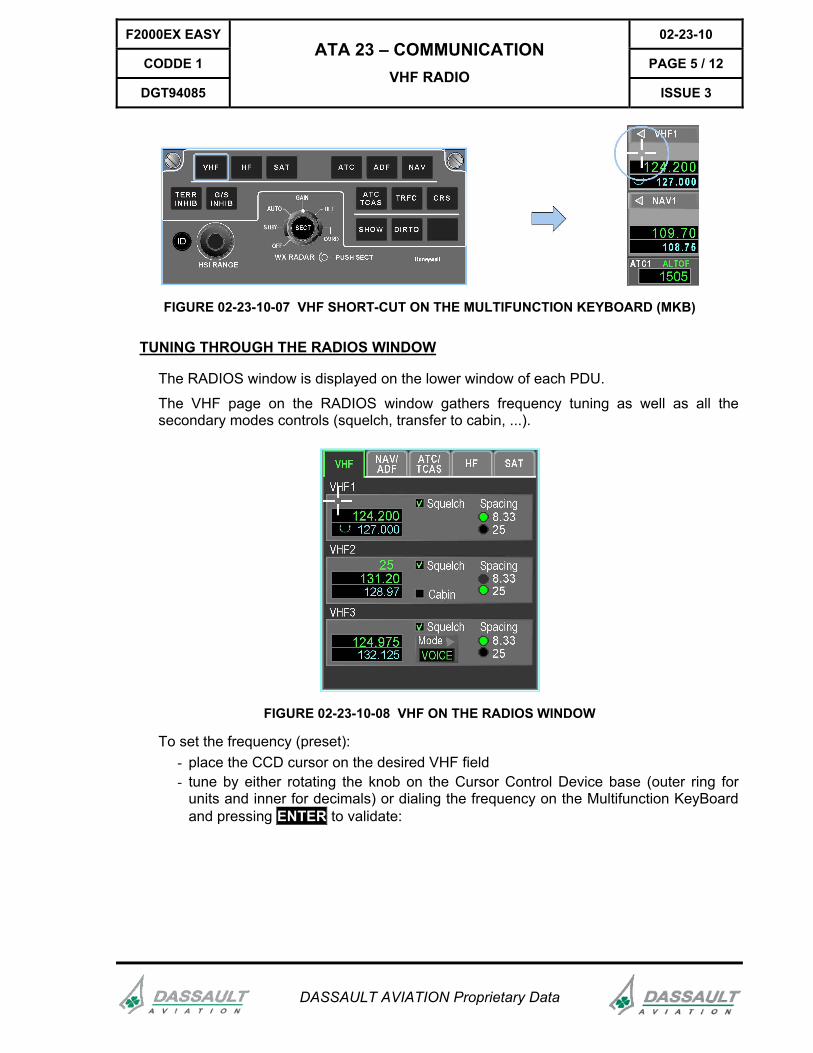
FIGURE 02-23-10-07 VHF SHORT-CUT ON THE MULTIFUNCTION KEYBOARD (MKB)
TUNING THROUGH THE RADIOS WINDOW
The RADIOS window is displayed on the lower window of each PDU.
The VHF page on the RADIOS window gathers frequency tuning as well as all the secondary modes controls (squelch, transfer to cabin, ...).
FIGURE 02-23-10-08 VHF ON THE RADIOS WINDOW
To set the frequency (preset): - place the CCD cursor on the desired VHF field - tune by either rotating the knob on the Cursor Control Device base (outer ring for
units and inner for decimals) or dialing the frequency on the Multifunction KeyBoard and pressing ENTER to validate:
02-23-10 F2000EX EASY
PAGE 6 / 12 CODDE 1
ISSUE 3
ATA 23 – COMMUNICATION VHF RADIO
DGT94085
DASSAULT AVIATION Proprietary Data
VHF NAV/ADF
ATC/TCAS HF SAT
VHF1
124.200127.000 25
8.33Squelch Spacing
VHF2or
E F
K L
Q R
W X
SPACE SWAP
1 2 3
4 5 6
7 8 9
0
ENTER
SHIFT
CLRDEL
WX RADAR HoneywellPUSH SECT
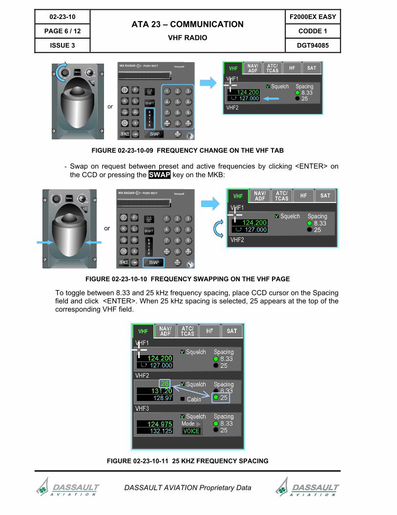
FIGURE 02-23-10-09 FREQUENCY CHANGE ON THE VHF TAB
- Swap on request between preset and active frequencies by clicking <ENTER> on the CCD or pressing the SWAP key on the MKB:
or
E F
K L
Q R
W X
SPACE SWAP
1 2 3
4 5 6
7 8 9
0
ENTER
SHIFT
CLRDEL
WX RADAR HoneywellPUSH SECTVHF NAV/
ADFATC/TCAS HF SAT
VHF1
124.200127.000 25
8.33Squelch Spacing
VHF2
FIGURE 02-23-10-10 FREQUENCY SWAPPING ON THE VHF PAGE
To toggle between 8.33 and 25 kHz frequency spacing, place CCD cursor on the Spacing field and click <ENTER>. When 25 kHz spacing is selected, 25 appears at the top of the corresponding VHF field.
FIGURE 02-23-10-11 25 KHZ FREQUENCY SPACING
F2000EX EASY 02-23-10
CODDE 1 PAGE 7 / 12
DGT94085
ATA 23 – COMMUNICATION VHF RADIO
ISSUE 3
DASSAULT AVIATION Proprietary Data
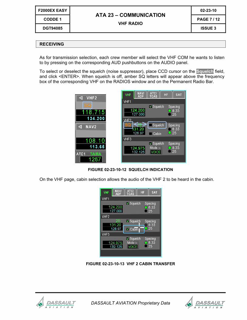
RECEIVING
As for transmission selection, each crew member will select the VHF COM he wants to listen to by pressing on the corresponding AUD pushbuttons on the AUDIO panel.
To select or deselect the squelch (noise suppressor), place CCD cursor on the Squelch field, and click <ENTER>. When squelch is off, amber SQ letters will appear above the frequency box of the corresponding VHF on the RADIOS window and on the Permanent Radio Bar.
FIGURE 02-23-10-12 SQUELCH INDICATION
On the VHF page, cabin selection allows the audio of the VHF 2 to be heard in the cabin.
FIGURE 02-23-10-13 VHF 2 CABIN TRANSFER
02-23-10 F2000EX EASY
PAGE 8 / 12 CODDE 1
ISSUE 3
ATA 23 – COMMUNICATION VHF RADIO
DGT94085
DASSAULT AVIATION Proprietary Data
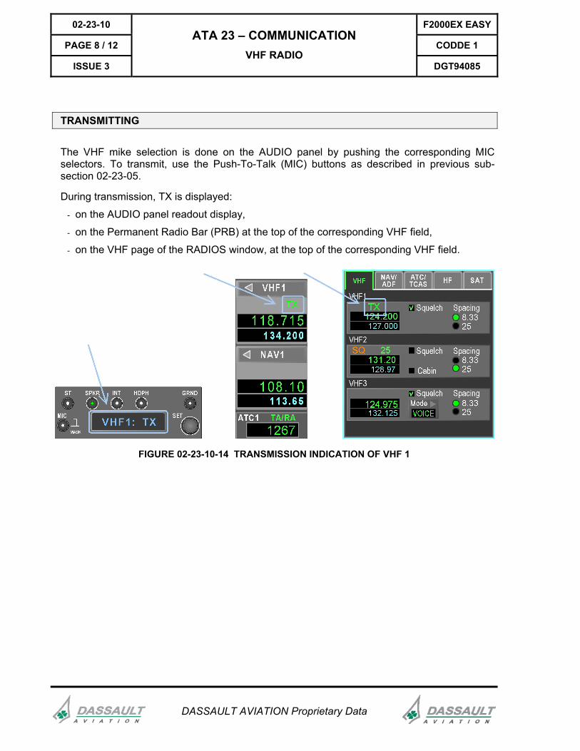
TRANSMITTING
The VHF mike selection is done on the AUDIO panel by pushing the corresponding MIC selectors. To transmit, use the Push-To-Talk (MIC) buttons as described in previous sub-section 02-23-05.
During transmission, TX is displayed:
- on the AUDIO panel readout display,
- on the Permanent Radio Bar (PRB) at the top of the corresponding VHF field,
- on the VHF page of the RADIOS window, at the top of the corresponding VHF field.
FIGURE 02-23-10-14 TRANSMISSION INDICATION OF VHF 1
F2000EX EASY 02-23-10
CODDE 1 PAGE 9 / 12
DGT94085
ATA 23 – COMMUNICATION VHF RADIO
ISSUE 3
DASSAULT AVIATION Proprietary Data
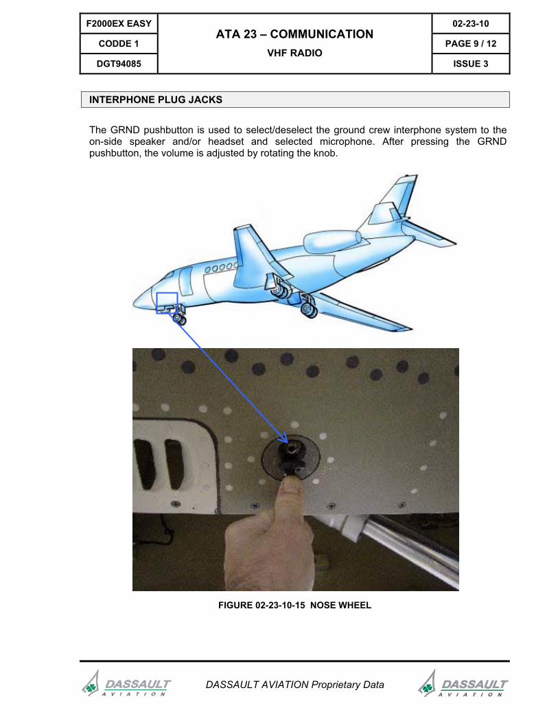
INTERPHONE PLUG JACKS
The GRND pushbutton is used to select/deselect the ground crew interphone system to the on-side speaker and/or headset and selected microphone. After pressing the GRND pushbutton, the volume is adjusted by rotating the knob.
FIGURE 02-23-10-15 NOSE WHEEL
02-23-10 F2000EX EASY
PAGE 10 / 12 CODDE 1
ISSUE 3
ATA 23 – COMMUNICATION VHF RADIO
DGT94085
DASSAULT AVIATION Proprietary Data
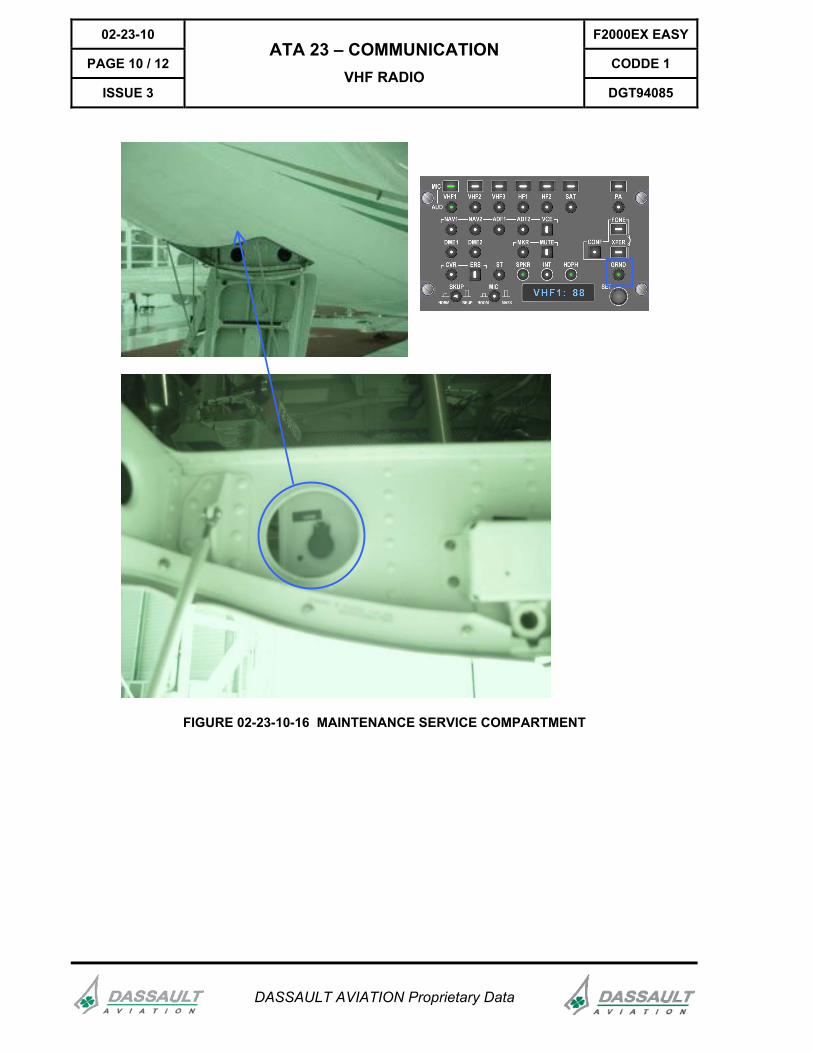
FIGURE 02-23-10-16 MAINTENANCE SERVICE COMPARTMENT
F2000EX EASY 02-23-10
CODDE 1 PAGE 11 / 12
DGT94085
ATA 23 – COMMUNICATION VHF RADIO
ISSUE 3
DASSAULT AVIATION Proprietary Data
ABNORMAL OPERATIONS
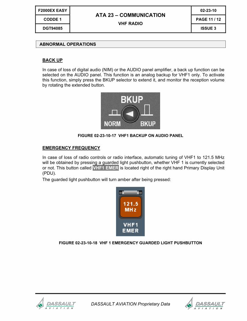
BACK UP
In case of loss of digital audio (NIM) or the AUDIO panel amplifier, a back up function can be selected on the AUDIO panel. This function is an analog backup for VHF1 only. To activate this function, simply press the BKUP selector to extend it, and monitor the reception volume by rotating the extended button.
FIGURE 02-23-10-17 VHF1 BACKUP ON AUDIO PANEL
EMERGENCY FREQUENCY
In case of loss of radio controls or radio interface, automatic tuning of VHF1 to 121.5 MHz will be obtained by pressing a guarded light pushbutton, whether VHF 1 is currently selected or not. This button called VHF1 EMER is located right of the right hand Primary Display Unit (PDU). The guarded light pushbutton will turn amber after being pressed:
FIGURE 02-23-10-18 VHF 1 EMERGENCY GUARDED LIGHT PUSHBUTTON

02-23-10 F2000EX EASY
PAGE 12 / 12 CODDE 1
ISSUE 3
ATA 23 – COMMUNICATION VHF RADIO
DGT94085
DASSAULT AVIATION Proprietary Data
INTENTIONALLY LEFT BLANK
F2000EX EASY 02-23-15
CODDE 1 PAGE 1 / 6
DGT94085
ATA 23 – COMMUNICATION HF RADIO
ISSUE 3
DASSAULT AVIATION Proprietary Data
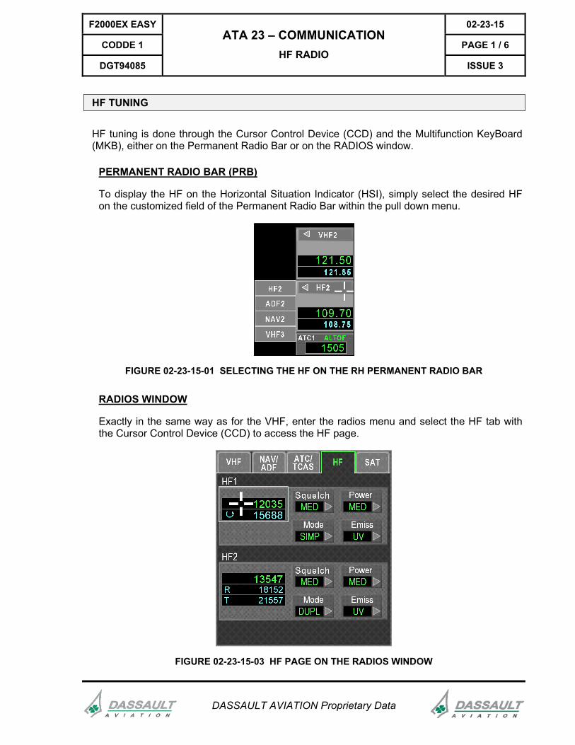
HF TUNING
HF tuning is done through the Cursor Control Device (CCD) and the Multifunction KeyBoard (MKB), either on the Permanent Radio Bar or on the RADIOS window.
PERMANENT RADIO BAR (PRB)
To display the HF on the Horizontal Situation Indicator (HSI), simply select the desired HF on the customized field of the Permanent Radio Bar within the pull down menu.
FIGURE 02-23-15-01 SELECTING THE HF ON THE RH PERMANENT RADIO BAR
RADIOS WINDOW
Exactly in the same way as for the VHF, enter the radios menu and select the HF tab with the Cursor Control Device (CCD) to access the HF page.
FIGURE 02-23-15-03 HF PAGE ON THE RADIOS WINDOW
02-23-15 F2000EX EASY
PAGE 2 / 6 CODDE 1
ISSUE 3
ATA 23 – COMMUNICATION HF RADIO
DGT94085
DASSAULT AVIATION Proprietary Data
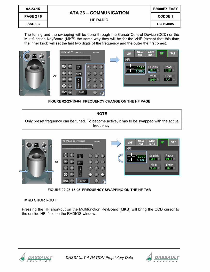
The tuning and the swapping will be done through the Cursor Control Device (CCD) or the Multifunction KeyBoard (MKB) the same way they will be for the VHF (except that this time the inner knob will set the last two digits of the frequency and the outer the first ones).
NAV/ADF
ATC/TCAS HF SAT
HF1
1203515688
or
E F
K L
Q R
W X
SPACE SWAP
1 2 3
4 5 6
7 8 9
0
ENTER
SHIFT
CLRDEL
WX RADAR HoneywellPUSH SECT VHF
ModeSIMP
SquelchMED
PowerMED
EmissUV
FIGURE 02-23-15-04 FREQUENCY CHANGE ON THE HF PAGE
NOTE
Only preset frequency can be tuned. To become active, it has to be swapped with the active frequency.
or
E F
K L
Q R
W X
SPACE SWAP
1 2 3
4 5 6
7 8 9
0
ENTER
SHIFT
CLRDEL
WX RADAR HoneywellPUSH SECT NAV/ADF
ATC/TCAS HF SAT
HF1
1203515688
VHF
ModeSIMP
SquelchMED
PowerMED
EmissUV
FIGURE 02-23-15-05 FREQUENCY SWAPPING ON THE HF TAB
MKB SHORT-CUT
Pressing the HF short-cut on the Multifunction KeyBoard (MKB) will bring the CCD cursor to the onside HF field on the RADIOS window.
F2000EX EASY 02-23-15
CODDE 1 PAGE 3 / 6
DGT94085
ATA 23 – COMMUNICATION HF RADIO
ISSUE 3
DASSAULT AVIATION Proprietary Data
ID
HSI RANGE
SEC T
AUTO
STBY
OFFOVRD
TILT
GAIN
WX RADAR HoneywellPUSH SECT
VHF HF SAT ATC ADF NAV
ATCTCAS TRFC CRS
SHOW DIRTO
TERRINHIB
G/SINHIB
NAV/ADF
ATC/TCAS HF SAT
HF1
1203515688
VHF
ModeSIMP
SquelchMED
PowerMED
EmissUV
1354718152
ModeSIMP
SquelchMED
PowerMED
EmissUV
21557TR
HF2
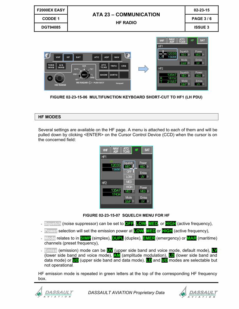
FIGURE 02-23-15-06 MULTIFUNCTION KEYBOARD SHORT-CUT TO HF1 (LH PDU)
HF MODES
Several settings are available on the HF page. A menu is attached to each of them and will be pulled down by clicking <ENTER> on the Cursor Control Device (CCD) when the cursor is on the concerned field:
NAV/ADF
ATC/TCAS HF SAT
HF1
1203515688
VHF
ModeSIMP
SquelchMED
PowerMED
EmissUV
1354717434
ModeSIMP
SquelchMED
PowerMED
EmissUV
HF2
OFF
HIGH
LOWMED
UV
FIGURE 02-23-15-07 SQUELCH MENU FOR HF
- Squelch (noise suppressor) can be set to OFF, LOW, MED, or HIGH (active frequency),
- Power selection will set the emission power at LOW, MED or HIGH (active frequency),
- Mode relates to in SIMP (simplex), DUPL (duplex), EMER (emergency) or MAR (maritime) channels (preset frequency),
- Emiss (emission) mode can be UV (upper side band and voice mode, default mode), LV (lower side band and voice mode), AM (amplitude modulation), LD (lower side band and data mode) or UD (upper side band and data mode). LD and UD modes are selectable but not operational.
HF emission mode is repeated in green letters at the top of the corresponding HF frequency box.
02-23-15 F2000EX EASY
PAGE 4 / 6 CODDE 1
ISSUE 3
ATA 23 – COMMUNICATION HF RADIO
DGT94085
DASSAULT AVIATION Proprietary Data
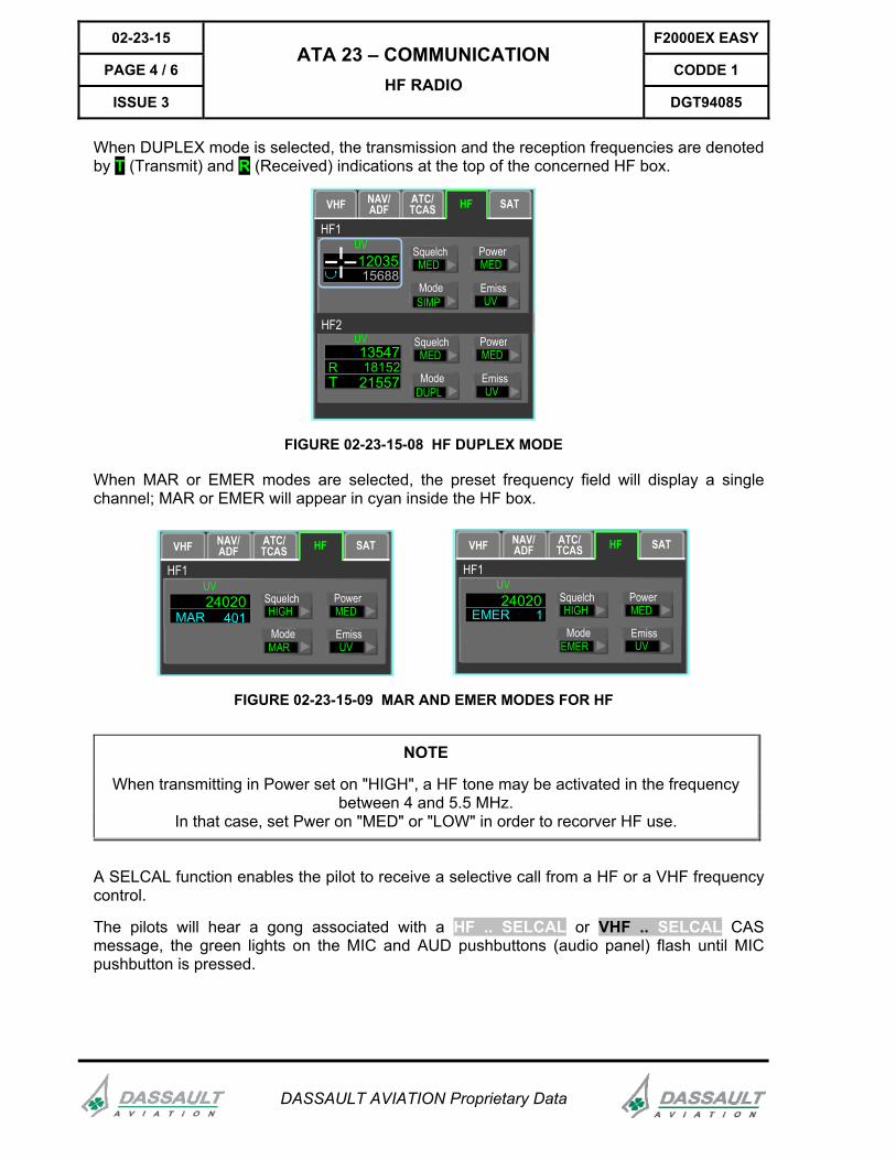
When DUPLEX mode is selected, the transmission and the reception frequencies are denoted by T (Transmit) and R (Received) indications at the top of the concerned HF box.
NAV/ADF
ATC/TCAS HF SAT
HF1
1203515688
VHF
ModeSIMP
SquelchMED
PowerMED
EmissUV
1354718152
ModeDUPL
SquelchMED
PowerMED
EmissUV21557T
R
HF2
UV
UV
FIGURE 02-23-15-08 HF DUPLEX MODE
When MAR or EMER modes are selected, the preset frequency field will display a single channel; MAR or EMER will appear in cyan inside the HF box.
NAV/ADF
ATC/TCAS HF SAT
HF1
24020401
VHF
ModeMAR
SquelchHIGH
PowerMED
EmissUV
MAR
NAV/ADF
ATC/TCAS HF SAT
HF1
240201
VHF
ModeEMER
SquelchHIGH
PowerMED
EmissUV
EMER
UVUV
FIGURE 02-23-15-09 MAR AND EMER MODES FOR HF
NOTE
When transmitting in Power set on "HIGH", a HF tone may be activated in the frequency between 4 and 5.5 MHz.
In that case, set Pwer on "MED" or "LOW" in order to recorver HF use.
A SELCAL function enables the pilot to receive a selective call from a HF or a VHF frequency control.
The pilots will hear a gong associated with a HF .. SELCAL or VHF .. SELCAL CAS message, the green lights on the MIC and AUD pushbuttons (audio panel) flash until MIC pushbutton is pressed.
F2000EX EASY 02-23-15
CODDE 1 PAGE 5 / 6
DGT94085
ATA 23 – COMMUNICATION HF RADIO
ISSUE 3
DASSAULT AVIATION Proprietary Data
RECEIVING
To receive, each crew member must select the HF he wants to listen to by pressing on the corresponding HF pushbuttons on the AUDIO panel.
For more information, refer to sub-section 02-23-05.
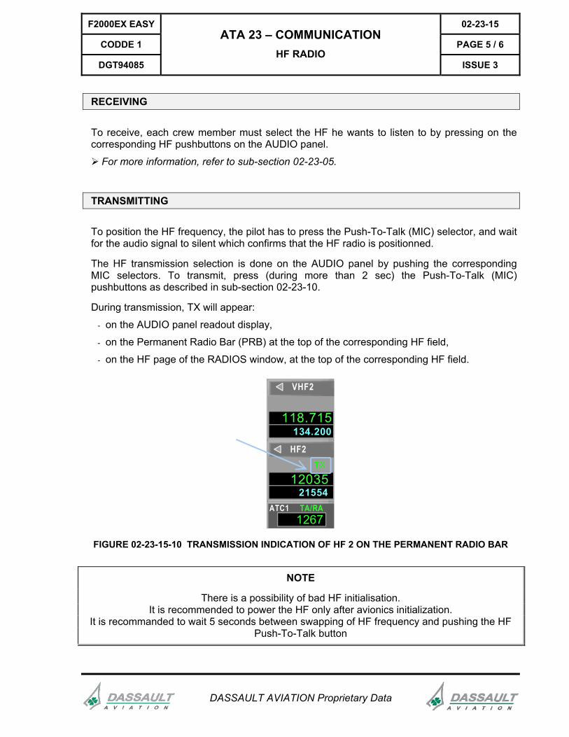
TRANSMITTING
To position the HF frequency, the pilot has to press the Push-To-Talk (MIC) selector, and wait for the audio signal to silent which confirms that the HF radio is positionned.
The HF transmission selection is done on the AUDIO panel by pushing the corresponding MIC selectors. To transmit, press (during more than 2 sec) the Push-To-Talk (MIC) pushbuttons as described in sub-section 02-23-10.
During transmission, TX will appear:
- on the AUDIO panel readout display,
- on the Permanent Radio Bar (PRB) at the top of the corresponding HF field,
- on the HF page of the RADIOS window, at the top of the corresponding HF field.
118.715134.200
VHF2
1203521554
HF2
ATC112771267
TA/RA
FIGURE 02-23-15-10 TRANSMISSION INDICATION OF HF 2 ON THE PERMANENT RADIO BAR
NOTE
There is a possibility of bad HF initialisation. It is recommended to power the HF only after avionics initialization.
It is recommanded to wait 5 seconds between swapping of HF frequency and pushing the HF Push-To-Talk button
02-23-15 F2000EX EASY
PAGE 6 / 6 CODDE 1
ISSUE 3
ATA 23 – COMMUNICATION HF RADIO
DGT94085
DASSAULT AVIATION Proprietary Data
INTENTIONALLY LEFT BLANK
F2000EX EASY 02-23-20
CODDE 1 PAGE 1 / 6
DGT94085
ATA 23 – COMMUNICATION RADIO-NAVIGATION
ISSUE 3
DASSAULT AVIATION Proprietary Data
INTRODUCTION
NAV (ILS / VOR / VOR-DME / VORTAC and TACAN) and ADF tuning and modes controls are done through the Cursor Control Device (CCD) or the Multifunction KeyBoard (MKB) either:
- on the Permanent Radio Bar (PRB),
- on the NAV / ADF tab of the RADIOS window.
NAV (ILS / VOR / VOR-DME / VORTAC AND TACAN)
NAV TUNING
Permanent Radio Bar (PRB)
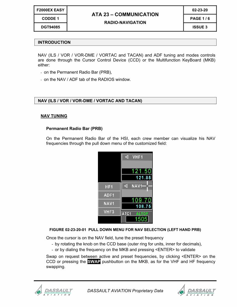
On the Permanent Radio Bar of the HSI, each crew member can visualize his NAV frequencies through the pull down menu of the customized field:
FIGURE 02-23-20-01 PULL DOWN MENU FOR NAV SELECTION (LEFT HAND PRB)
Once the cursor is on the NAV field, tune the preset frequency - by rotating the knob on the CCD base (outer ring for units, inner for decimals), - or by dialing the frequency on the MKB and pressing <ENTER> to validate
Swap on request between active and preset frequencies, by clicking <ENTER> on the CCD or pressing the SWAP pushbutton on the MKB, as for the VHF and HF frequency swapping.
02-23-20 F2000EX EASY
PAGE 2 / 6 CODDE 1
ISSUE 3
ATA 23 – COMMUNICATION RADIO-NAVIGATION
DGT94085
DASSAULT AVIATION Proprietary Data
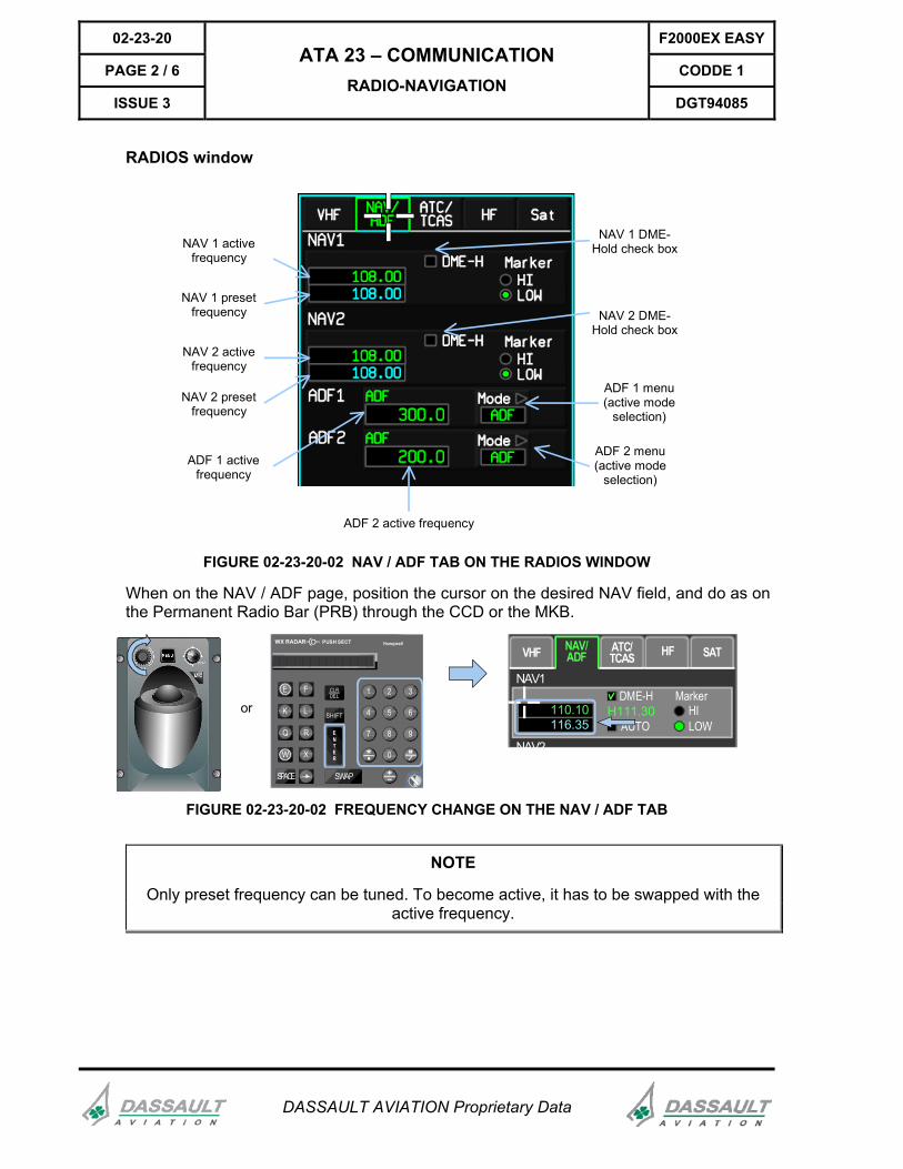
RADIOS window
NAV 2 activefrequency
NAV 1 presetfrequency
NAV 2 presetfrequency
NAV 1 activefrequency
NAV 2 DME-Hold check box
NAV 1 DME-Hold check box
ADF 1 menu(active mode
selection)
ADF 2 menu(active mode
selection)
ADF 2 active frequency
ADF 1 activefrequency
FIGURE 02-23-20-02 NAV / ADF TAB ON THE RADIOS WINDOW
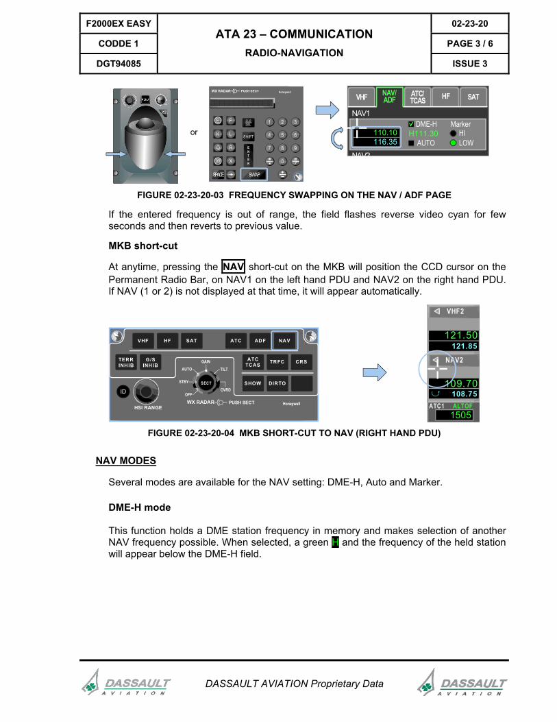
When on the NAV / ADF page, position the cursor on the desired NAV field, and do as on the Permanent Radio Bar (PRB) through the CCD or the MKB.
orE F
K L
Q R
W X
SPACE SWAP
1 2 3
4 5 6
7 8 9
0
ENTER
SHIFT
CLRDEL
WX RADAR HoneywellPUSH SECT NAV/ADF
NAV1
HFVHF
DME-H
AUTO
Marker
LOWHI110.10
116.35H111.30
ATC/TCAS SAT
NAV2
FIGURE 02-23-20-02 FREQUENCY CHANGE ON THE NAV / ADF TAB
NOTE
Only preset frequency can be tuned. To become active, it has to be swapped with the active frequency.
F2000EX EASY 02-23-20
CODDE 1 PAGE 3 / 6
DGT94085
ATA 23 – COMMUNICATION RADIO-NAVIGATION
ISSUE 3
DASSAULT AVIATION Proprietary Data
orE F
K L
Q R
W X
SPACE SWAP
1 2 3
4 5 6
7 8 9
0
ENTER
SHIFT
CLRDEL
WX RADAR HoneywellPUSH SECT NAV/ADF
NAV1
HFVHF
DME-H
AUTO
Marker
LOWHI110.10
116.35H111.30
ATC/TCAS SAT
NAV2
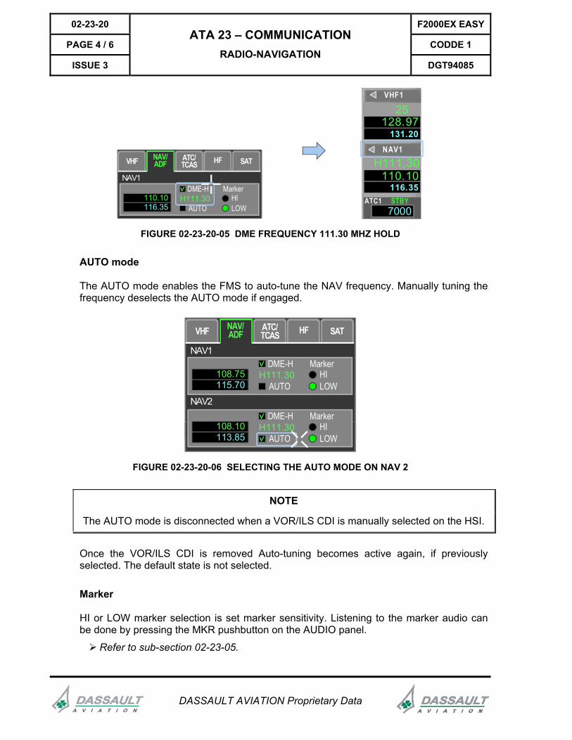
FIGURE 02-23-20-03 FREQUENCY SWAPPING ON THE NAV / ADF PAGE
If the entered frequency is out of range, the field flashes reverse video cyan for few seconds and then reverts to previous value.
MKB short-cut
At anytime, pressing the NAV short-cut on the MKB will position the CCD cursor on the Permanent Radio Bar, on NAV1 on the left hand PDU and NAV2 on the right hand PDU. If NAV (1 or 2) is not displayed at that time, it will appear automatically.
ID
HSI RANGE
SECT
AUTO
STBY
OFFOVRD
TILT
GAIN
WX RADAR HoneywellPUSH SECT
VHF HF SAT ATC ADF NAV
ATCTCAS TRFC CRS
SHOW DIRTO
TERRINHIB
G/SINHIB
121.50121.85
VHF2
109.70108.75
NAV2
ATC112771505
ALTOF
FIGURE 02-23-20-04 MKB SHORT-CUT TO NAV (RIGHT HAND PDU)
NAV MODES
Several modes are available for the NAV setting: DME-H, Auto and Marker.
DME-H mode
This function holds a DME station frequency in memory and makes selection of another NAV frequency possible. When selected, a green H and the frequency of the held station will appear below the DME-H field.
02-23-20 F2000EX EASY
PAGE 4 / 6 CODDE 1
ISSUE 3
ATA 23 – COMMUNICATION RADIO-NAVIGATION
DGT94085
DASSAULT AVIATION Proprietary Data
128.97131.20
VHF1
110.10116.35
NAV1
ATC112777000
STBY
H111.30
25
NAV/ADF
NAV1
HFVHF
DME-H
AUTO
Marker
LOWHI110.10
116.35H111.30
ATC/TCAS SAT
FIGURE 02-23-20-05 DME FREQUENCY 111.30 MHZ HOLD
AUTO mode
The AUTO mode enables the FMS to auto-tune the NAV frequency. Manually tuning the frequency deselects the AUTO mode if engaged.
NAV/ADF
NAV1
HFVHF
DME-H
AUTO
Marker
LOWHI108.75
115.70H111.30
ATC/TCAS SAT
NAV2DME-H
AUTO
Marker
LOWHI108.10
113.85H111.30
FIGURE 02-23-20-06 SELECTING THE AUTO MODE ON NAV 2
NOTE
The AUTO mode is disconnected when a VOR/ILS CDI is manually selected on the HSI.
Once the VOR/ILS CDI is removed Auto-tuning becomes active again, if previously selected. The default state is not selected.
Marker
HI or LOW marker selection is set marker sensitivity. Listening to the marker audio can be done by pressing the MKR pushbutton on the AUDIO panel.
Refer to sub-section 02-23-05.
F2000EX EASY 02-23-20
CODDE 1 PAGE 5 / 6
DGT94085
ATA 23 – COMMUNICATION RADIO-NAVIGATION
ISSUE 3
DASSAULT AVIATION Proprietary Data
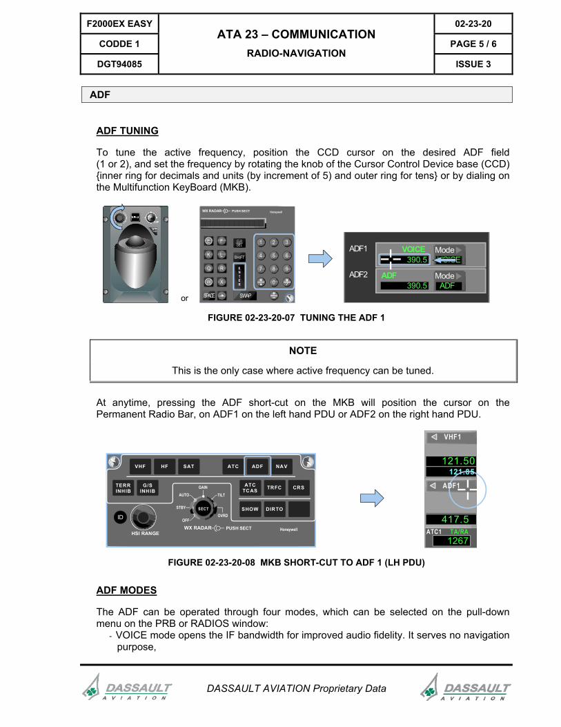
ADF
ADF TUNING
To tune the active frequency, position the CCD cursor on the desired ADF field (1 or 2), and set the frequency by rotating the knob of the Cursor Control Device base (CCD) {inner ring for decimals and units (by increment of 5) and outer ring for tens} or by dialing on the Multifunction KeyBoard (MKB).
or
E F
K L
Q R
W X
SPACE SWAP
1 2 3
4 5 6
7 8 9
0
ENTER
SHIFT
CLRDEL
WX RADAR HoneywellPUSH SECT
ADF1 ModeVOICE
VOICE390.5
ADF2 ModeADF
ADF390.5
FIGURE 02-23-20-07 TUNING THE ADF 1
NOTE
This is the only case where active frequency can be tuned.
At anytime, pressing the ADF short-cut on the MKB will position the cursor on the Permanent Radio Bar, on ADF1 on the left hand PDU or ADF2 on the right hand PDU.
ID
HSI RANGE
SECT
AUTO
STBY
OFFOVRD
TILT
GAIN
WX RADAR HoneywellPUSH SECT
VHF HF SAT ATC ADF NAV
ATCTCAS TRFC CRS
SHOW DIRTO
TERRINHIB
G/SINHIB
121.50121.85
VHF1
417.5ATC1
12771267TA/RA
ADF1
FIGURE 02-23-20-08 MKB SHORT-CUT TO ADF 1 (LH PDU)
ADF MODES
The ADF can be operated through four modes, which can be selected on the pull-down menu on the PRB or RADIOS window:
- VOICE mode opens the IF bandwidth for improved audio fidelity. It serves no navigation purpose,
02-23-20 F2000EX EASY
PAGE 6 / 6 CODDE 1
ISSUE 3
ATA 23 – COMMUNICATION RADIO-NAVIGATION
DGT94085
DASSAULT AVIATION Proprietary Data
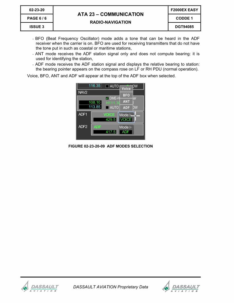
- BFO (Beat Frequency Oscillator) mode adds a tone that can be heard in the ADF receiver when the carrier is on. BFO are used for receiving transmitters that do not have the tone put in such as coastal or maritime stations,
- ANT mode receives the ADF station signal only and does not compute bearing: it is used for identifying the station,
- ADF mode receives the ADF station signal and displays the relative bearing to station: the bearing pointer appears on the compass rose on LF or RH PDU (normal operation).
Voice, BFO, ANT and ADF will appear at the top of the ADF box when selected.
AUTO LOW116.35
NAV2DME-H
AUTO
Marker
LOWHI108.10
113.85H111.30
ADF1 ModeVOICE
VOICE429.5
ADF2 ModeADF
ADF417.5
Voice
ADF
BFOANT
FIGURE 02-23-20-09 ADF MODES SELECTION
F2000EX EASY 02-23-30
CODDE 1 PAGE 1 / 8
DGT94085
ATA 23 – COMMUNICATION CMF/AFIS
ISSUE 3
DASSAULT AVIATION Proprietary Data
INTRODUCTION
The Communication Management Function (CMF)/Airborne Flight Information System (AFIS) is an option not part of basic certification.
The CMF/AFIS consists of the following airplane components:
- Communication Management Unit (CMU),
- Satellite Data Unit (optional),
- High Power Amplifier (optional),
- Satellite Antenna (optional),
- VHF3 in data mode (optional)
The CMF formats data for sending to the ground from the airplane using the VHF or satellite network. The CMF incorporates a data quality transceiver. The transceiver is tuned automatically by the CMF to use the appropriate VHF ground station for the purpose of transmitting data to and receiving data from the Global Data Center (GDC) while in flight.
The CMF can be interfaced to one printer.
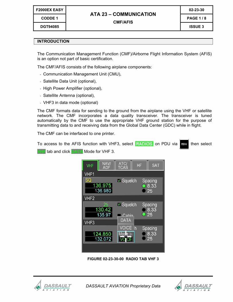
To access to the AFIS function with VHF3, select on PDU via then select
VHF tab and click DATA Mode for VHF 3.
FIGURE 02-23-30-00 RADIO TAB VHF 3
02-23-30 F2000EX EASY
PAGE 2 / 8 CODDE 1
ISSUE 3
ATA 23 – COMMUNICATION CMF / AFIS
DGT94085
DASSAULT AVIATION Proprietary Data
To access the AFIS function with SATCOM, select CMF/AFIS on MDU via then select
STATUS/CONFIG tab and click Auto in Satellite Links field.
When both VHF3 and SATCOM are installed, VHF3 will be automatically selected, unless VHF3 cannot receive data anymore or SATCOM is forced.
Only one CMF/AFIS window is allowed in an MDU at a time.
The AFIS window provides six main tabs:
- Status/Config (default tab),
- Winds,
- Term XW,
- SIGMETS,
- Rx Msg,
- Tx Msg.
F2000EX EASY 02-23-30
CODDE 1 PAGE 3 / 8
DGT94085
ATA 23 – COMMUNICATION CMF/AFIS
ISSUE 3
DASSAULT AVIATION Proprietary Data
STATUS / CONFIG TAB
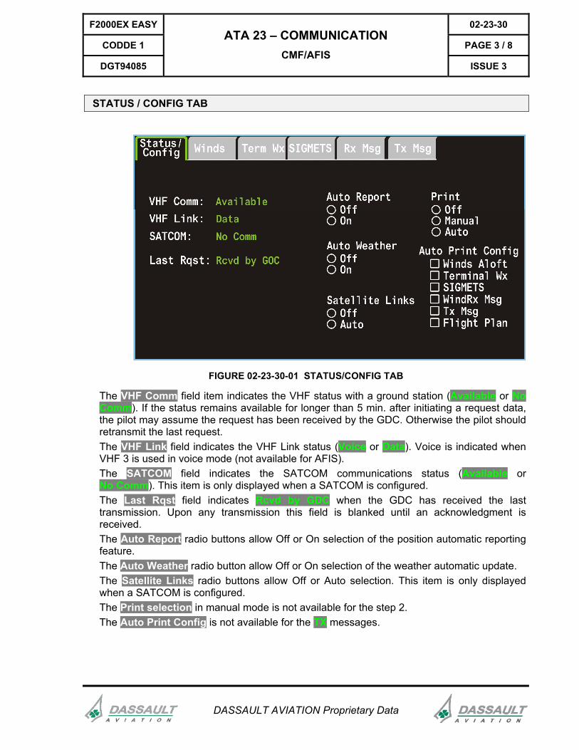
FIGURE 02-23-30-01 STATUS/CONFIG TAB
The VHF Comm field item indicates the VHF status with a ground station (Available or No Comm). If the status remains available for longer than 5 min. after initiating a request data, the pilot may assume the request has been received by the GDC. Otherwise the pilot should retransmit the last request. The VHF Link field indicates the VHF Link status (Voice or Data). Voice is indicated when VHF 3 is used in voice mode (not available for AFIS). The SATCOM field indicates the SATCOM communications status (Available or No Comm). This item is only displayed when a SATCOM is configured. The Last Rqst field indicates Rcvd by GDC when the GDC has received the last transmission. Upon any transmission this field is blanked until an acknowledgment is received. The Auto Report radio buttons allow Off or On selection of the position automatic reporting feature. The Auto Weather radio button allow Off or On selection of the weather automatic update. The Satellite Links radio buttons allow Off or Auto selection. This item is only displayed when a SATCOM is configured. The Print selection in manual mode is not available for the step 2. The Auto Print Config is not available for the TX messages.
02-23-30 F2000EX EASY
PAGE 4 / 8 CODDE 1
ISSUE 3
ATA 23 – COMMUNICATION CMF / AFIS
DGT94085
DASSAULT AVIATION Proprietary Data
WINDS TAB
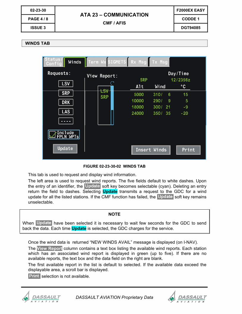
FIGURE 02-23-30-02 WINDS TAB
This tab is used to request and display wind information. The left area is used to request wind reports. The five fields default to white dashes. Upon the entry of an identifier, the soft key becomes selectable (cyan). Deleting an entry return the field to dashes. Selecting Update transmits a request to the GDC for a wind update for all the listed stations. If the CMF function has failed, the soft key remains unselectable.
NOTE
When have been selected it is necessary to wait few seconds for the GDC to send back the data. Each time Update is selected, the GDC charges for the service.
Once the wind data is returned “NEW WINDS AVAIL” message is displayed (on I-NAV). The View Report column contains a text box listing the available wind reports. Each station which has an associated wind report is displayed in green (up to five). If there are no available reports, the text box and the data field on the right are blank. The first available report in the list is default to selected. If the available data exceed the displayable area, a scroll bar is displayed.
selection is not available.
F2000EX EASY 02-23-30
CODDE 1 PAGE 5 / 8
DGT94085
ATA 23 – COMMUNICATION CMF/AFIS
ISSUE 3
DASSAULT AVIATION Proprietary Data
TERM WX TAB
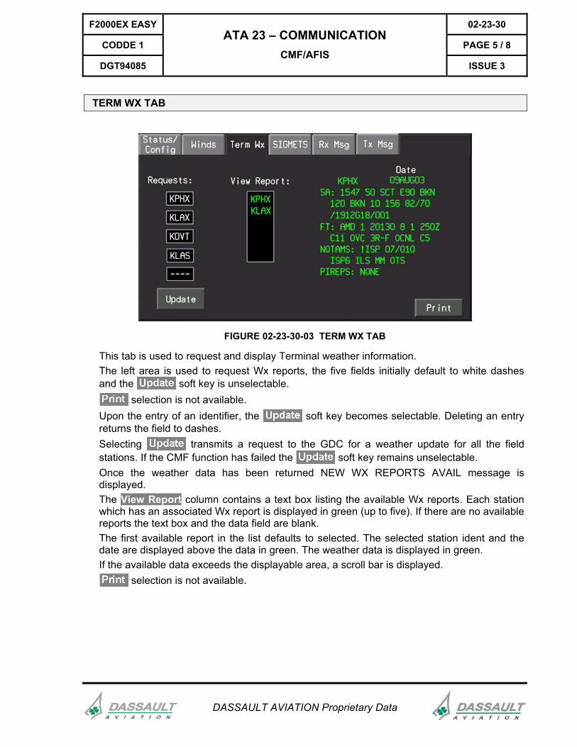
FIGURE 02-23-30-03 TERM WX TAB
This tab is used to request and display Terminal weather information. The left area is used to request Wx reports, the five fields initially default to white dashes and the soft key is unselectable.
selection is not available. Upon the entry of an identifier, the soft key becomes selectable. Deleting an entry returns the field to dashes. Selecting transmits a request to the GDC for a weather update for all the field stations. If the CMF function has failed the soft key remains unselectable. Once the weather data has been returned NEW WX REPORTS AVAIL message is displayed. The View Report column contains a text box listing the available Wx reports. Each station which has an associated Wx report is displayed in green (up to five). If there are no available reports the text box and the data field are blank. The first available report in the list defaults to selected. The selected station ident and the date are displayed above the data in green. The weather data is displayed in green. If the available data exceeds the displayable area, a scroll bar is displayed.
selection is not available.
02-23-30 F2000EX EASY
PAGE 6 / 8 CODDE 1
ISSUE 3
ATA 23 – COMMUNICATION CMF / AFIS
DGT94085
DASSAULT AVIATION Proprietary Data
SIGMETS TAB
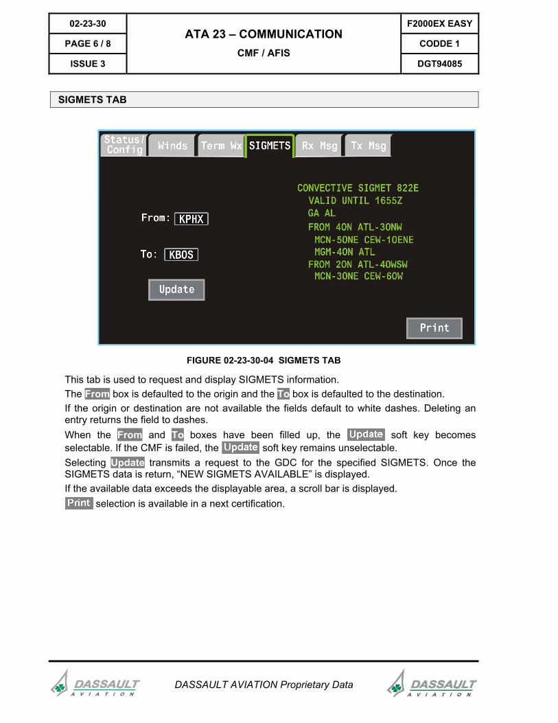
FIGURE 02-23-30-04 SIGMETS TAB
This tab is used to request and display SIGMETS information. The From box is defaulted to the origin and the To box is defaulted to the destination. If the origin or destination are not available the fields default to white dashes. Deleting an entry returns the field to dashes. When the From and To boxes have been filled up, the soft key becomes selectable. If the CMF is failed, the soft key remains unselectable. Selecting Update transmits a request to the GDC for the specified SIGMETS. Once the SIGMETS data is return, “NEW SIGMETS AVAILABLE” is displayed. If the available data exceeds the displayable area, a scroll bar is displayed.
selection is available in a next certification.
F2000EX EASY 02-23-30
CODDE 1 PAGE 7 / 8
DGT94085
ATA 23 – COMMUNICATION CMF/AFIS
ISSUE 3
DASSAULT AVIATION Proprietary Data
RX MSG TAB
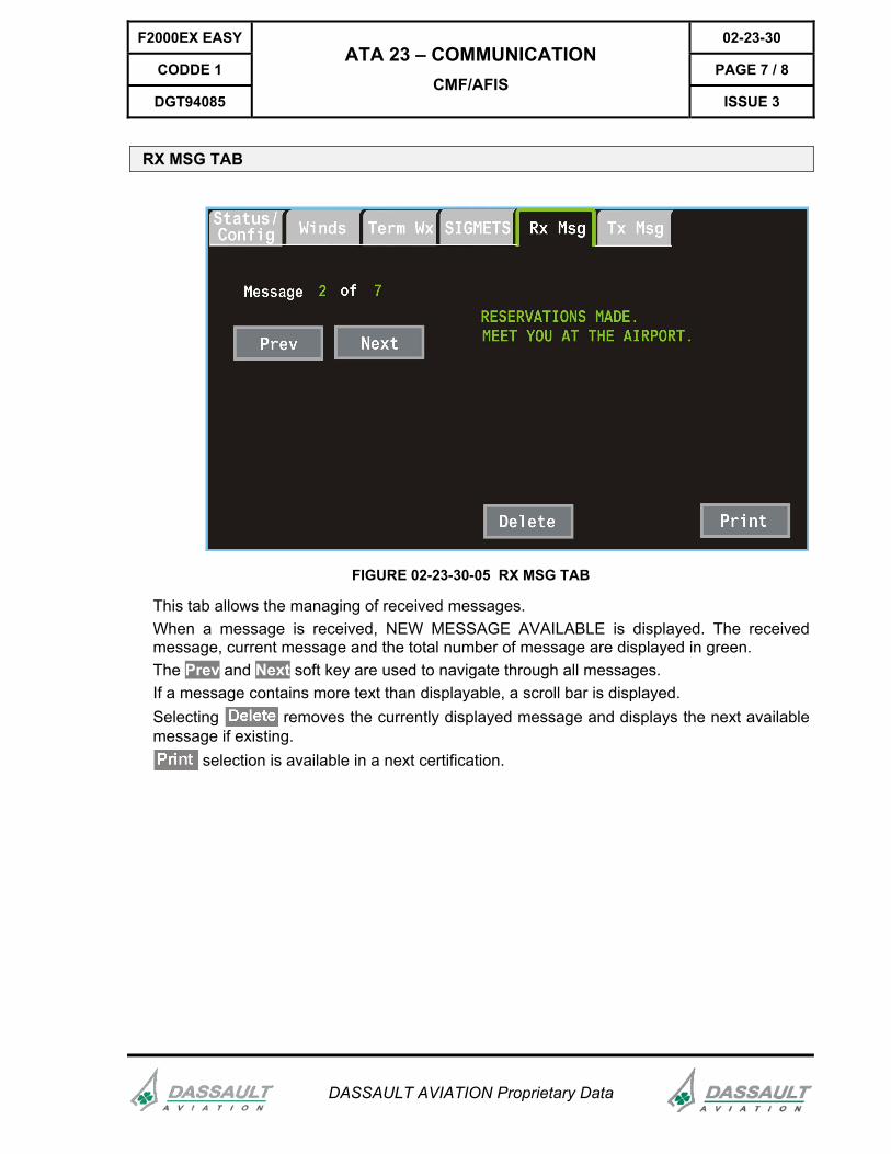
FIGURE 02-23-30-05 RX MSG TAB
This tab allows the managing of received messages. When a message is received, NEW MESSAGE AVAILABLE is displayed. The received message, current message and the total number of message are displayed in green. The Prev and Next soft key are used to navigate through all messages. If a message contains more text than displayable, a scroll bar is displayed. Selecting removes the currently displayed message and displays the next available message if existing.
selection is available in a next certification.
02-23-30 F2000EX EASY
PAGE 8 / 8 CODDE 1
ISSUE 3
ATA 23 – COMMUNICATION CMF / AFIS
DGT94085
DASSAULT AVIATION Proprietary Data
TX MSG TAB
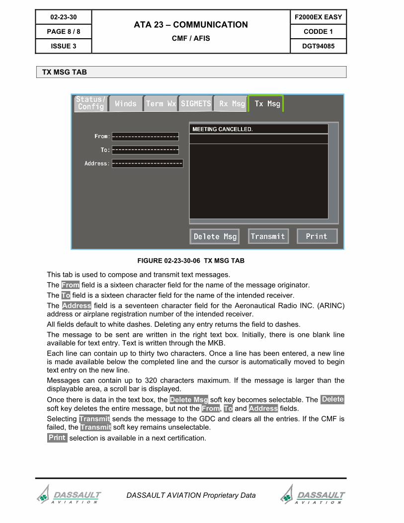
FIGURE 02-23-30-06 TX MSG TAB
This tab is used to compose and transmit text messages. The From field is a sixteen character field for the name of the message originator. The To field is a sixteen character field for the name of the intended receiver. The Address field is a seventeen character field for the Aeronautical Radio INC. (ARINC) address or airplane registration number of the intended receiver. All fields default to white dashes. Deleting any entry returns the field to dashes. The message to be sent are written in the right text box. Initially, there is one blank line available for text entry. Text is written through the MKB. Each line can contain up to thirty two characters. Once a line has been entered, a new line is made available below the completed line and the cursor is automatically moved to begin text entry on the new line. Messages can contain up to 320 characters maximum. If the message is larger than the displayable area, a scroll bar is displayed. Once there is data in the text box, the Delete Msg soft key becomes selectable. The soft key deletes the entire message, but not the From, To and Address fields. Selecting Transmit sends the message to the GDC and clears all the entries. If the CMF is failed, the Transmit soft key remains unselectable.
selection is available in a next certification.
F2000EX EASY 02-23-35
CODDE 1 PAGE 1 / 2
DGT94085
ATA 23 – COMMUNICATION ABNORMAL OPERATION
ISSUE 3
DASSAULT AVIATION Proprietary Data
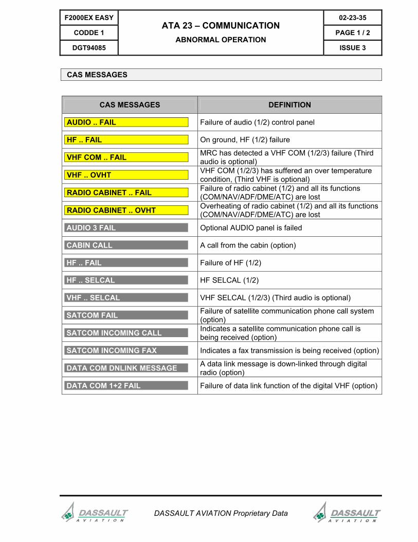
CAS MESSAGES
CAS MESSAGES DEFINITION
AUDIO .. FAIL Failure of audio (1/2) control panel
HF .. FAIL On ground, HF (1/2) failure
VHF COM .. FAIL MRC has detected a VHF COM (1/2/3) failure (Third audio is optional)
VHF .. OVHT VHF COM (1/2/3) has suffered an over temperature condition, (Third VHF is optional)
RADIO CABINET .. FAIL Failure of radio cabinet (1/2) and all its functions (COM/NAV/ADF/DME/ATC) are lost
RADIO CABINET .. OVHT Overheating of radio cabinet (1/2) and all its functions (COM/NAV/ADF/DME/ATC) are lost
AUDIO 3 FAIL Optional AUDIO panel is failed
CABIN CALL A call from the cabin (option)
HF .. FAIL Failure of HF (1/2)
HF .. SELCAL HF SELCAL (1/2)
VHF .. SELCAL VHF SELCAL (1/2/3) (Third audio is optional)
SATCOM FAIL Failure of satellite communication phone call system (option)
SATCOM INCOMING CALL Indicates a satellite communication phone call is being received (option)
SATCOM INCOMING FAX Indicates a fax transmission is being received (option)
DATA COM DNLINK MESSAGE A data link message is down-linked through digital radio (option)
DATA COM 1+2 FAIL Failure of data link function of the digital VHF (option)
02-23-35 F2000EX EASY
PAGE 2 / 2 CODDE 1
ISSUE 3
ATA 23 – COMMUNICATION ABNORMAL OPERATION
DGT94085
DASSAULT AVIATION Proprietary Data
INTENTIONALLY LEFT BLANK