Embed Size (px)
Citation preview
Advantech AE Technical Share DocumentDate 2016/02/16 Release Note ■Internal ■ External Category ■FAQ□SOP Related OS Windows
Abstract How to setup GPIO on PPC-6150/6170Keyword GPIO,PPC-6150/6170Related Product PPC-6150/6170
Problem Description Some customer would like to know how to control GPIO for their application in OS.
Brief Solution - Step by Step: Step1, Install SUSI.If the customer wants to configure the GPIO (I/O Write) on PPC-6150/6170, install the SUSIV4.0.The download link as belowhttp://support.advantech.com.tw/Support/SearchResult.aspx?keyword=PPC-6150&searchtabs=BIOS,Certificate,Datasheet,Driver,Firmware,Manual,Online Training,Software Utility,Utility,FAQ,Installation,Software API,Software API Manual&select_tab=Utility
During the SUSI installation, do a complete installation.
After SUSI is installed, in the direction of where you install SUSI:

User manual for SUSI The .h file location .lib and .dll file location
You can write your own software; these files can be used by them.
Step2. GPIO demo (multiple pin)
Please type in the Value”11111111” at multiple pin text box.Multiple Pin text box determine GPIO pin which was enable or disable. Multiple pinValue 1 0Function Enable Disable
Please type in the Value”00000000” at the Direction text box.Direction text box determine GPIO pin which was Input or Output. DirectionValue 1 0Pin Direction Input Output
Please type in the Value”11111111” at status text box.Status text box determine GPIO pin which was 5V or 0V. StatusValue 1 0Pin Voltage 5V 0V
Please click the “Set Direction” then click the”I/O Write”

All above the setting as below the picture
After you finished the all setting, will get the 5V from each pin as below
Note: The left bit represent GPIO 7 pin and the right bit represent GPIO 0 pin as below picture
If you type in the Value”00001111” at Status text box as below

GPIO 0-3 pins are 5V and GPIO 4-7 pins are 0V
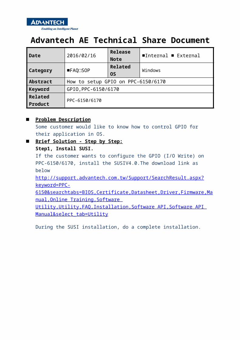
GPIO demo (single pin)Make it simple connect GPIO 0 and GPIO1 only Setting GPIO 0 direction to 0 (output), level to 0(Low), press “Set” for direction and level.
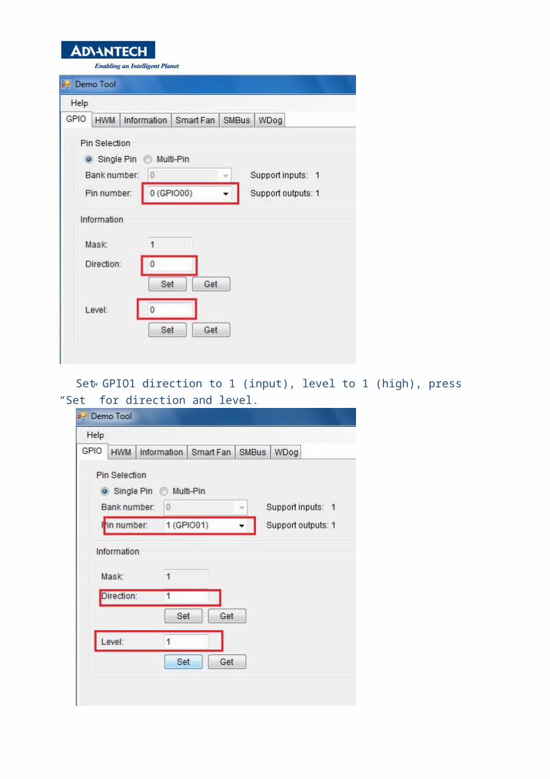
Set GPIO1 direction to 1 (input), level to 1 (high), press “Set” for direction and level.
Press “get” in level for GPIO1, After “get” is pressed, notice that the level goes from 1 to 0.