Embed Size (px)
Citation preview

Design Failure Mode and Effects Analysis (DFMEA) Instructions
NOTE: Design FMEAs must be prepared for all programs (components, subassemblies and assemblies)
where Johnson Controls has full program design responsibility. In cases where the OEM Customer has
design responsibility, every effort must be made to document special and safety critical special
characteristics for inclusion in the Design FMEA and Control Plan. (A matrix for this purpose and the
FMEA Form can be found in the AIAG APQP and Control Plan manual).
INSTRUCTIONS:
1. The System FMEA and/or Design FMEA are to be prepared using the DaimlerChrysler, Ford, and General
Motors Potential Failure Mode and Effects Analysis (FMEA) reference manual.
2. Historical campaign, warranty data, high mileage data and P-Diagram noise factors must be reviewed and
included in the DFMEA as applicable.
3. Similar part/program DFMEA's must be considered when preparing a DFMEA for all new programs.
4. The SFMEA and/or DFMEA must identify and address all Special Characteristics (both significant and
critical).
5. Design characteristics that affect high risk priority failure modes must be identified.
6. Appropriate corrective actions must be assigned to high risk priority numbers (RPN 70 and greater).
7. Appropriate corrective actions must be planned and/or taken for high severity numbers (severity of 7 and
greater).
8. Risk priorities must be revised when corrective actions have been completed and verified.
9. Customer system design specifications numbers must be indicated for each failure mode. (i.e. Ford SDS
v4.0, ST-0018 and GM SOR-SSTS xxx)
10. DFMEAs must address all failure modes in areas of Safety, Function, Service, Appearance, BSR,
Assembly, Packaging and Comfort.
WW-PLUS-FR-04-31-E / Rev 01 Page 1 of 29

POTENTIAL
FAILURE MODE AND EFFECTS ANALYSIS
(DESIGN FMEA)
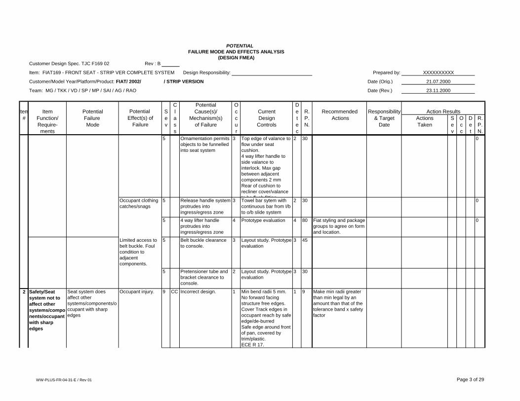
Customer Design Spec. TJC F169 02 Rev : B
Item: FIAT169 - FRONT SEAT - STRIP VER COMPLETE SYSTEM Design Responsibility: Prepared by: XXXXXXXXXX
Customer/Model Year/Platform/Product: FIAT/ 2002/ / STRIP VERSION Date (Orig.) 21.07.2000
Team: MG / TKK / VD / SP / MP / SAI / AG / RAO Date (Rev.) 23.11.2000
C Potential O D
Item Item Potential Potential S l Cause(s)/ c Current e R. Recommended Responsibility Action Results
# Function/ Failure Effect(s) of e a Mechanism(s) c Design t P. Actions & Target Actions S O D R.
Require- Mode Failure v s of Failure u Controls e N. Date Taken e c e P.
ments s r c v c t N.
Assy Front seat
238442, 238443
1 Safety/ Seat
System to
provide flush
fitting
components/mi
n. clearance to
components
with relative
motion
Seat System does not
provide flush fitting
components/min.
clearance to
components with
relative motion
Occupants finger
becomes trapped.
5 SC Incorrect gap size
specified on
valance/recliner covers
3 Seat side
valance/recliner cover
to cushion gap to be
less than 5 mm or
greater than 20 mm.
2 30 0
5 Incorrect gap size
specified on flip up
cushion system
3 Flip up cushion
mechanism to
occupant handle
location to be less than
5 mm or greater than
20 mm.
2 30 0
5 4 way lifter handle grip
area to side valance
gap size incorrectly
specified
3 During arc of
movement lever grip
area not to be within 30
mm of side
valance/door bin
3 45
5 Recliner handwheel
grip area to recliner
cover gap size
incorrectly specified
2 Recliner handwheel to
recliner cover to be
less than 5 mm or
greater than 20 mm.
2 20 0
Occupants
belongings fall into
seat system
5 Incorrect gap sizes
specified within seat
system
3 Layout study. Prototype
evaluation
2 30 0
WW-PLUS-FR-04-31-E / Rev 01 Page 2 of 29
POTENTIAL
FAILURE MODE AND EFFECTS ANALYSIS
(DESIGN FMEA)
Customer Design Spec. TJC F169 02 Rev : B
Item: FIAT169 - FRONT SEAT - STRIP VER COMPLETE SYSTEM Design Responsibility: Prepared by: XXXXXXXXXX
Customer/Model Year/Platform/Product: FIAT/ 2002/ / STRIP VERSION Date (Orig.) 21.07.2000
Team: MG / TKK / VD / SP / MP / SAI / AG / RAO Date (Rev.) 23.11.2000
C Potential O D
Item Item Potential Potential S l Cause(s)/ c Current e R. Recommended Responsibility Action Results
# Function/ Failure Effect(s) of e a Mechanism(s) c Design t P. Actions & Target Actions S O D R.
Require- Mode Failure v s of Failure u Controls e N. Date Taken e c e P.
ments s r c v c t N.
5 Ornamentation permits
objects to be funnelled
into seat system
3 Top edge of valance to
flow under seat
cushion.
4 way lifter handle to
side valance to
interlock. Max gap
between adjacent
components 2 mm
Rear of cushion to
recliner cover/valance
to be flush fitting
2 30 0
Occupant clothing
catches/snags
5 Release handle system
protrudes into
ingress/egress zone
3 Towel bar sytem with
continuous bar from I/b
to o/b slide system
2 30 0
5 4 way lifter handle
protrudes into
ingress/egress zone
4 Prototype evaluation 4 80 Fiat styling and package
groups to agree on form
and location.
0
Limited access to
belt buckle. Foul
condition to
adjacent
components.
5 Belt buckle clearance
to console.
3 Layout study. Prototype
evaluation
3 45
5 Pretensioner tube and
bracket clearance to
console.
2 Layout study. Prototype
evaluation
3 30
2 Safety/Seat
system not to
affect other
systems/compo
nents/occupant
with sharp
edges
Seat system does
affect other
systems/components/o
ccupant with sharp
edges
Occupant injury. 9 CC Incorrect design. 1 Min bend radii 5 mm.
No forward facing
structure free edges.
Cover Track edges in
occupant reach by safe
edge/de-burred
Safe edge around front
of pan, covered by
trim/plastic.
ECE R 17.
1 9 Make min radii greater
than min legal by an
amount than that of the
tolerance band x safety
factor
WW-PLUS-FR-04-31-E / Rev 01 Page 3 of 29

POTENTIAL
FAILURE MODE AND EFFECTS ANALYSIS
(DESIGN FMEA)
Customer Design Spec. TJC F169 02 Rev : B
Item: FIAT169 - FRONT SEAT - STRIP VER COMPLETE SYSTEM Design Responsibility: Prepared by: XXXXXXXXXX
Customer/Model Year/Platform/Product: FIAT/ 2002/ / STRIP VERSION Date (Orig.) 21.07.2000
Team: MG / TKK / VD / SP / MP / SAI / AG / RAO Date (Rev.) 23.11.2000
C Potential O D
Item Item Potential Potential S l Cause(s)/ c Current e R. Recommended Responsibility Action Results
# Function/ Failure Effect(s) of e a Mechanism(s) c Design t P. Actions & Target Actions S O D R.
Require- Mode Failure v s of Failure u Controls e N. Date Taken e c e P.
ments s r c v c t N.
9 SC Towel bar track release
sytem grip area
1 Dia 10 mm min tube.
Layout study and
prototype evaluation
1 9
9 SC 4 way lifter lever grip
area
2 Radii Min 2 mm.
Smooth profile
Plastic grip area with
no tool parting lines in
grip area
2 36
9 SC Recliner handwheel
grip area
2 Santoprene outer grip
area
Plastic housing - Min
rad 0.5 mm.
2 36
9 SC Valance/recliner cover
edge
2 Full rad around
perimeter (Styling
approval required from
Fiat)
No tooling split lines on
A surface or self
presenting to
2 36 0
Seat belt damage. 9 YC Incorrect desiign of
upper cross member
may make sharp edges
possible.
1 Protection cap fitted to
all front seat back
frames.
This fixture was POKE
YOKE in all JIT plants.
1 9
9 YC Forward facing edges 1 Layout study. Prototype
evaluation
1 9
3 Safety/Seat
system to
provide a fire
resistant
system.
Seat system does not
provide a fire resistant
system.
Occupant injury. 9 YC Incorrect material
specification.
2 Material specifications.
FMVSS 302.
2 36 0
WW-PLUS-FR-04-31-E / Rev 01 Page 4 of 29

POTENTIAL
FAILURE MODE AND EFFECTS ANALYSIS
(DESIGN FMEA)
Customer Design Spec. TJC F169 02 Rev : B
Item: FIAT169 - FRONT SEAT - STRIP VER COMPLETE SYSTEM Design Responsibility: Prepared by: XXXXXXXXXX
Customer/Model Year/Platform/Product: FIAT/ 2002/ / STRIP VERSION Date (Orig.) 21.07.2000
Team: MG / TKK / VD / SP / MP / SAI / AG / RAO Date (Rev.) 23.11.2000
C Potential O D
Item Item Potential Potential S l Cause(s)/ c Current e R. Recommended Responsibility Action Results
# Function/ Failure Effect(s) of e a Mechanism(s) c Design t P. Actions & Target Actions S O D R.
Require- Mode Failure v s of Failure u Controls e N. Date Taken e c e P.
ments s r c v c t N.
4 Safety/Seat
system to
provide an
electrically safe
system
Seat system does not
provide an electrically
safe system
Occupant injury. 9 YC Incorrect specification
ofelectrical
components.
2 Legal legislation.
Electrical system
specification.
Controlled by supplier
TRW according to Fiat
specifications.
2 36 0
9 YC Incorrect cable routing 1 Route cables to protect
from side impact. Fiat
approval required.
3 27 0
9 YC Water ingress into
connector system
2 Locate away from
water ingress zone.
If in zones use sealed
type connector
systems
2 36 0
Electrical system
failiure.
6 Loss of electrical signal 3 Connector to connector
latching strength - 100
N min.
Free cable length for
height adjust and flip
up cushion systems.
Mount connectors on
seat with fore/aft
2 36 0
5 Safety/Seat
system to
provide an
ocupant with a
protected
environment.
System does not
provide a protected
environment for the
occupant.
Occupant injury. 9 YC Headrestraint becomes
detached from seat
structure
3 Notch depth 2.0 mm
Button diameter 0.8
mm ECE R
25.04
ECE R 17.07
2 54
9 YC Incorrect Packaging. 2 Layout study, Prototype
evaluation, Customer
sign off.
2 36 0
10 YC Incorrect material
selection
2 Material specifications
based on FEA,
Surrogate parts
2 40
WW-PLUS-FR-04-31-E / Rev 01 Page 5 of 29

POTENTIAL
FAILURE MODE AND EFFECTS ANALYSIS
(DESIGN FMEA)
Customer Design Spec. TJC F169 02 Rev : B
Item: FIAT169 - FRONT SEAT - STRIP VER COMPLETE SYSTEM Design Responsibility: Prepared by: XXXXXXXXXX
Customer/Model Year/Platform/Product: FIAT/ 2002/ / STRIP VERSION Date (Orig.) 21.07.2000
Team: MG / TKK / VD / SP / MP / SAI / AG / RAO Date (Rev.) 23.11.2000
C Potential O D
Item Item Potential Potential S l Cause(s)/ c Current e R. Recommended Responsibility Action Results
# Function/ Failure Effect(s) of e a Mechanism(s) c Design t P. Actions & Target Actions S O D R.
Require- Mode Failure v s of Failure u Controls e N. Date Taken e c e P.
ments s r c v c t N.
6 Safety/Seat
system to
provide correct
package
clearances.
System does not
provide correct layout
clearances.
Customer
dissatisfaction.
7 YS Seat movemnts
incomplete due to
interference within
structure
2 Kinematic studies in
CAD, Functional seat
build
3 42 0
7 YS Seat movemnts
incomplete due to
interference with other
systems
3 Kinematic studies in
CAD, Prototype
evaluation in vehicle
2 42 0
7 Safety/Seat
system to
provide
adequate
strength under
static and/or
dynamic
loadings
Seat system does not
provide adequate
strength under static
and/or dynamic
loadings
Occupant injury. 10 YC New seat structure
design/Incorrect
design.
2 ECE R 14.05,ECE R
16.04,ECE 17.07,ECE
R 21.01,ECE R
25.04,ECE R
94.01,ECE R 95.01
Engineering issues list.
Customer sign off.
Homologation.
Surrogate structure
3 60
10 YC Flipup cushion self
activates
2 Front X tube interlock
load path with pan
ECE 17
ECE 14, Surrogate
mechanism
2 40
8 Safety/Seat
user adjust
components to
provide
adequate
strength under
static and/or
dynamic
loadings
Seat user adjust
components do not
provide adequate
strength under static
and/or dynamic
loadings
Loss of
adjustment/feature
function
8 YS Incorrect specification
on material section
2 FEA
Free body diagrams
Surrogate mechanisms
2 32
WW-PLUS-FR-04-31-E / Rev 01 Page 6 of 29

POTENTIAL
FAILURE MODE AND EFFECTS ANALYSIS
(DESIGN FMEA)
Customer Design Spec. TJC F169 02 Rev : B
Item: FIAT169 - FRONT SEAT - STRIP VER COMPLETE SYSTEM Design Responsibility: Prepared by: XXXXXXXXXX
Customer/Model Year/Platform/Product: FIAT/ 2002/ / STRIP VERSION Date (Orig.) 21.07.2000
Team: MG / TKK / VD / SP / MP / SAI / AG / RAO Date (Rev.) 23.11.2000
C Potential O D
Item Item Potential Potential S l Cause(s)/ c Current e R. Recommended Responsibility Action Results
# Function/ Failure Effect(s) of e a Mechanism(s) c Design t P. Actions & Target Actions S O D R.
Require- Mode Failure v s of Failure u Controls e N. Date Taken e c e P.
ments s r c v c t N.
8 YS Incorrect material
specification.
2 FEA
Free body diagrams
Surrogate mechanisms
2 32
8 YS Incorrect use abuse
loadings specified
2 For finger use levers -
150 N For
hand use levers - 250
N Surrogate
mechanisms
2 32
9 General/Seat
system to
resist
excessive
freeplay
Seat system does not
resist excessive
freeplay
Customer
experiences some
disatisfaction
5 Front seat back fore/aft
movement - recliner
heart
2 T2000 heart. 4 fixngs
of recliner to track
system - 5 dr. Latch
type claw Surrogate
mechanism
2 20
5 4 way linkage
mechanism
3 Reduce freeplay at
eack pivot location.
Rear lift system with
frre pivot at front.
Single likage system to
reduce interfaces.
Tolerance study.
Surrogate mechanism
2 30 0
10 Comfort/Seat
system to
provide
adequate
suspension
and support.
System does not
provide adequate
supension and support.
Customer
dissatisfaction.
7 YS Loss of cushion
support
2 Dead pan design
90 mm Foam depth
under H point at centre
line.
Engineering issues list.
Customer sign off.
JCI knee test -
simulate user kneeing
on cushion facing rear
of seat.
Pressure mapping.
2 28 0
WW-PLUS-FR-04-31-E / Rev 01 Page 7 of 29

POTENTIAL
FAILURE MODE AND EFFECTS ANALYSIS
(DESIGN FMEA)
Customer Design Spec. TJC F169 02 Rev : B
Item: FIAT169 - FRONT SEAT - STRIP VER COMPLETE SYSTEM Design Responsibility: Prepared by: XXXXXXXXXX
Customer/Model Year/Platform/Product: FIAT/ 2002/ / STRIP VERSION Date (Orig.) 21.07.2000
Team: MG / TKK / VD / SP / MP / SAI / AG / RAO Date (Rev.) 23.11.2000
C Potential O D
Item Item Potential Potential S l Cause(s)/ c Current e R. Recommended Responsibility Action Results
# Function/ Failure Effect(s) of e a Mechanism(s) c Design t P. Actions & Target Actions S O D R.
Require- Mode Failure v s of Failure u Controls e N. Date Taken e c e P.
ments s r c v c t N.
7 YS Incorrect package. 3 Layout study.
Customer sign off.
Packaging issues list.
Pressure mapping.
Rear occupant foot
zone profile - 25 mm
clearance to underside
of pan.
2 42 0
7 YS Loss of FSB
suspension mat
support
3 Clip suspension mat
direct to frame
2 42 0
Occupant
discomfort
6 YS Incorrect A surface
design.
2 JCI design guidelines.
Engineering issues list.
Customer sign off.
2 24 0
6 YS Loss of specified H
point, back angle, thigh
angle, heel point.
3 JCI knee test -
simulate user kneeing
on cushion facing rear
of seat.
H pt on complete seat
dwg.
2 36 0
6 YS Incorrect foam
hardness specified
3 Foam hardness,
density and weight to
be monitored. Link with
H-point checks
2 36
11 Comfort/Seat
system
provides an
optimum
pressure
distribution and
support.
System does not
provide optimum
pressure distribution
and support.
Customer
experiences some
disatisfaction
5 Incorrect A surface
design
3 Customer sign off on
ergonomic curves.
Pressure mapping.
2 30 0
WW-PLUS-FR-04-31-E / Rev 01 Page 8 of 29

POTENTIAL
FAILURE MODE AND EFFECTS ANALYSIS
(DESIGN FMEA)
Customer Design Spec. TJC F169 02 Rev : B
Item: FIAT169 - FRONT SEAT - STRIP VER COMPLETE SYSTEM Design Responsibility: Prepared by: XXXXXXXXXX
Customer/Model Year/Platform/Product: FIAT/ 2002/ / STRIP VERSION Date (Orig.) 21.07.2000
Team: MG / TKK / VD / SP / MP / SAI / AG / RAO Date (Rev.) 23.11.2000
C Potential O D
Item Item Potential Potential S l Cause(s)/ c Current e R. Recommended Responsibility Action Results
# Function/ Failure Effect(s) of e a Mechanism(s) c Design t P. Actions & Target Actions S O D R.
Require- Mode Failure v s of Failure u Controls e N. Date Taken e c e P.
ments s r c v c t N.
5 Incorrect Foam
specification
3 JCI design guidelines.
Engineering issues list.
Customer sign off.
Pressure mapping.
2 30 0
5 Incorrect location of B
surface on FSC and
FSB
3 Pan B surface to be 90
mm from A surface
under H point at seat
centre line
Prressure map test
Meat to metal
clearance to be min 30
mm
2 30 0
12 Comfort/seat
system
provides
adequate
movement and
adjustment.
System does not
provide adequate
movement and
adjustment.
Customer
experiences some
dissatisfaction.
5 Incorrect package
specification.
3 Seat slide travel 150
mm forward, 60 mm
rearward.
Height adjust range +/-
20 mm rear lift
Back angle design
position 25 deg,
rearward from vertical,
+/- 15 deg min for
comfort (larger angle
posible for additional
package requirements)
Track angle 2 deg
Height adjust lever
swing +/- 20 deg from
start position
Towel bar swing 10
deg from start position
System design
specification.
Engineering issues list.
Customer sign off.
2 30 0
WW-PLUS-FR-04-31-E / Rev 01 Page 9 of 29

POTENTIAL
FAILURE MODE AND EFFECTS ANALYSIS
(DESIGN FMEA)
Customer Design Spec. TJC F169 02 Rev : B
Item: FIAT169 - FRONT SEAT - STRIP VER COMPLETE SYSTEM Design Responsibility: Prepared by: XXXXXXXXXX
Customer/Model Year/Platform/Product: FIAT/ 2002/ / STRIP VERSION Date (Orig.) 21.07.2000
Team: MG / TKK / VD / SP / MP / SAI / AG / RAO Date (Rev.) 23.11.2000
C Potential O D
Item Item Potential Potential S l Cause(s)/ c Current e R. Recommended Responsibility Action Results
# Function/ Failure Effect(s) of e a Mechanism(s) c Design t P. Actions & Target Actions S O D R.
Require- Mode Failure v s of Failure u Controls e N. Date Taken e c e P.
ments s r c v c t N.
13 Comfort/Syste
m to provide
sufficient
vertical travel
System does not
provide sufficient
vertical travel.
Customert
experiences some
dissatisfaction.
5 Incorrect design. 3 Engineering issues list.
Customer sign off.
2 30 0
System
ergonomically
unsuitable for
occupant.
5 Incorrect design. 3 JCI design guidelines.
Engineering issues list.
Customer sign off.
2 30 0
0
Occupant
discomfort
6 YS Incorrect design. 3 JCI design guidelines.
Engineering issues list.
Customer sign off.
2 36 0
14 Comfort/Syste
m to provide
sufficient
recline
adjustment.
System does not
provide sufficient
recline adjustment.
Occupant
discomfort
6 YS Incorrect location of
end stops
3 Design position 25 deg
rearward of vertical.
Min comfort adjustment
range +/-15 deg about
design position.
Package review
Additional package
adjustment for
horizontal rearward
condition. (Seat fore aft
position can be forward
of design in vehicle to
prevent clash with rear
seat cushion)
2 36 0
6 YS Lower edge of front
seat back interfeance
with rear of cushion
when reclined
rearward. (Condition
worst when cushion is
raised to highest
vertical position)
4 Soft to soft interfance
with structure having
min40 mm clearance
between sweep paths.
(Trim bulging -
appearance affected.
Degree determined by
biteline overlap)
3 72
WW-PLUS-FR-04-31-E / Rev 01 Page 10 of 29

POTENTIAL
FAILURE MODE AND EFFECTS ANALYSIS
(DESIGN FMEA)
Customer Design Spec. TJC F169 02 Rev : B
Item: FIAT169 - FRONT SEAT - STRIP VER COMPLETE SYSTEM Design Responsibility: Prepared by: XXXXXXXXXX
Customer/Model Year/Platform/Product: FIAT/ 2002/ / STRIP VERSION Date (Orig.) 21.07.2000
Team: MG / TKK / VD / SP / MP / SAI / AG / RAO Date (Rev.) 23.11.2000
C Potential O D
Item Item Potential Potential S l Cause(s)/ c Current e R. Recommended Responsibility Action Results
# Function/ Failure Effect(s) of e a Mechanism(s) c Design t P. Actions & Target Actions S O D R.
Require- Mode Failure v s of Failure u Controls e N. Date Taken e c e P.
ments s r c v c t N.
15 Comfort/Syste
m to provide
sufficient
headrest
adjustment.
System does not
provide sufficient
headrest adjustment.
Occupant
discomfort
6 YS Incorrect noth location
specified
3 Package review 2 36 0
Does not meet
legal height
9 YC Incorrect package
location
3 ECE 17 2 54 0
16 Comfort/Seat to
provide
adequate
ingress -
egress
clearance.
Seat does not provide
adequate ingress -
egress clearance.
Customer
experiences some
dissatisfaction.
5 Track infringment into
rear footwell
3 Reduced length
outboard lower track
section
Customer sign off.
Packaging issues list.
Package checks.
3 45
5 Recliner cover/valance
infringement into
occupant path
3 Tailor plastic covers
close to structure. Min.
structure to be
determined.
Customer sign off.
Packaging issues list.
Package checks.
3 45
17 Comfort/Seat
system to
provide good
ergonomic
position
Seat system does not
provide good
ergonomic poition.
Customer
experiences some
dissatisfaction.
5 Incorrect H point, heel
point, back angle
specifed
3 Fiat approved
packaging details
2 30 0
5 Towel bar release
system incorrectly
positioned
3 Min 20 mm clearance
under lever to vehicle
carpet over front cross
member.
Jury evaluation for
reach
3 45 0
WW-PLUS-FR-04-31-E / Rev 01 Page 11 of 29

POTENTIAL
FAILURE MODE AND EFFECTS ANALYSIS
(DESIGN FMEA)
Customer Design Spec. TJC F169 02 Rev : B
Item: FIAT169 - FRONT SEAT - STRIP VER COMPLETE SYSTEM Design Responsibility: Prepared by: XXXXXXXXXX
Customer/Model Year/Platform/Product: FIAT/ 2002/ / STRIP VERSION Date (Orig.) 21.07.2000
Team: MG / TKK / VD / SP / MP / SAI / AG / RAO Date (Rev.) 23.11.2000
C Potential O D
Item Item Potential Potential S l Cause(s)/ c Current e R. Recommended Responsibility Action Results
# Function/ Failure Effect(s) of e a Mechanism(s) c Design t P. Actions & Target Actions S O D R.
Require- Mode Failure v s of Failure u Controls e N. Date Taken e c e P.
ments s r c v c t N.
5 4 way lifter handle
incorrectly positioned
3 Jury evaluation for
reach
Fiat package and
styling review
3 45 0
18 Comfort/Seat
system to
provide
optimum
pressures
distribution for
long term
comfort.
Seat system does not
provide optimum
pressures distribution
for long term comfort.
Customer
experiences some
dissatisfaction.
5 Incorrect A surface
profile
3 Presssure map
A surface profiles
generated from
surrogate and
benchmark data
2 30 0
5 Uncorrect B surface
location of Pan and
FSB suspension mat
3 FSC - 90 mm foam
depth under H point at
centre line of seat
Pressure map test
2 30 0
5 Incorrect foam
specification
3 Pressure map test
Component FMEA
control of foam
hardness, density and
weight.
2 30 0
5 Incorrect trim tension 3 Pressure map test
Combine with baggy
seat test evaluation.
2 30 0
5 Incorrect meat to metal
clearances
3 Min 30 mm
Package sections
Pressure map test
2 30 0
5 Incorrect seat system
adjustment
2 Fiat agreed adjustment
ranges.
Forward - 150 mm
Rearward - 60 mm
Vertical - +/- 20 mm
Recline - min +/- 15
deg
2 20 0
WW-PLUS-FR-04-31-E / Rev 01 Page 12 of 29

POTENTIAL
FAILURE MODE AND EFFECTS ANALYSIS
(DESIGN FMEA)
Customer Design Spec. TJC F169 02 Rev : B
Item: FIAT169 - FRONT SEAT - STRIP VER COMPLETE SYSTEM Design Responsibility: Prepared by: XXXXXXXXXX
Customer/Model Year/Platform/Product: FIAT/ 2002/ / STRIP VERSION Date (Orig.) 21.07.2000
Team: MG / TKK / VD / SP / MP / SAI / AG / RAO Date (Rev.) 23.11.2000
C Potential O D
Item Item Potential Potential S l Cause(s)/ c Current e R. Recommended Responsibility Action Results
# Function/ Failure Effect(s) of e a Mechanism(s) c Design t P. Actions & Target Actions S O D R.
Require- Mode Failure v s of Failure u Controls e N. Date Taken e c e P.
ments s r c v c t N.
19 Comfort/Seat
system to
provide lifetime
comfort.
Seat system does not
provide lifetime
comfort.
Customer
experiences some
disatisfaction
5 Foam collapse 2 Component FMEA to
identify controls.
ST-0036 followed by
pressure map and
Durability test
4 40
Loss of primary
function of FSC
8 YS Suspension system
collapse
3 Durability test
Dead pan FSC
2 48 0
20 Comfort/Seat
system to
provide
adequate meat
to metal
clearance
Seat system does not
provide adequate meat
to metal clearance
Occupant
dissatisfaction.
6 Incorrect location of
structure
3 Min 30 mm meat to
metal
2 36 0
21 Appearance/Se
at system to
provide no or
consistant
gaps at
component/sub
system
interfaces
Seat system does not
provide no or
consistant gaps at
component/sub system
interfaces
Defect noticed by
most customers
4 Incorrect profiles
specified
5 Customer sign-off
Eval 1 - exercise to
involve measuring
consistency of gaps.
4 80 0
4 Incorrect mating of
components/sub
systems
5 Interlock edges of
ornamentation
Customer sign-off
4 80 0
4 Incorrect profile of FSB
top surface and
underside of headrest
asy
5 Angle top of FSB to car
line
4 80 0
4 4 way lifter handle
profile mis-match with
valance
5 Fiat styling review 4 80 0
WW-PLUS-FR-04-31-E / Rev 01 Page 13 of 29

POTENTIAL
FAILURE MODE AND EFFECTS ANALYSIS
(DESIGN FMEA)
Customer Design Spec. TJC F169 02 Rev : B
Item: FIAT169 - FRONT SEAT - STRIP VER COMPLETE SYSTEM Design Responsibility: Prepared by: XXXXXXXXXX
Customer/Model Year/Platform/Product: FIAT/ 2002/ / STRIP VERSION Date (Orig.) 21.07.2000
Team: MG / TKK / VD / SP / MP / SAI / AG / RAO Date (Rev.) 23.11.2000
C Potential O D
Item Item Potential Potential S l Cause(s)/ c Current e R. Recommended Responsibility Action Results
# Function/ Failure Effect(s) of e a Mechanism(s) c Design t P. Actions & Target Actions S O D R.
Require- Mode Failure v s of Failure u Controls e N. Date Taken e c e P.
ments s r c v c t N.
22 Appearance/Se
at system to
conceal
internal
materials.
Seat system does not
conceal internal
materials.
Occupant some
dissatisfaction.
5 Visible foam at base of
FSB - recliner region
5 Lower J retainer to
run full length of FSB
Customer sign off.
4 100 0
5 Visible recliner
structure when FSB
reclined away from
design position
4 Recliner cover to
feature return edges.
Customer sign off.
4 80 0
5 Seat structure visible
when flip up cushion is
in up position - in order
to access stowage
compartment
3 Stowage box to cover
slide mechanism
Paint cross tubes
3 45 Clip in trim cover
system.
Stowage box to produce
false profile.
0
5 Cabling system visible
in car line
3 Dedicated fixed cable
routing
2 30 Check for cable
visibility during flip up
operation.
Check for cable visibility
with seat mounted in
vehicl in full package
range.
0
5 Ornamentation
disengages from seat
system occupant
3 Pull out forces to be
specified to all
ornamentation
3 45
WW-PLUS-FR-04-31-E / Rev 01 Page 14 of 29

POTENTIAL
FAILURE MODE AND EFFECTS ANALYSIS
(DESIGN FMEA)
Customer Design Spec. TJC F169 02 Rev : B
Item: FIAT169 - FRONT SEAT - STRIP VER COMPLETE SYSTEM Design Responsibility: Prepared by: XXXXXXXXXX
Customer/Model Year/Platform/Product: FIAT/ 2002/ / STRIP VERSION Date (Orig.) 21.07.2000
Team: MG / TKK / VD / SP / MP / SAI / AG / RAO Date (Rev.) 23.11.2000
C Potential O D
Item Item Potential Potential S l Cause(s)/ c Current e R. Recommended Responsibility Action Results
# Function/ Failure Effect(s) of e a Mechanism(s) c Design t P. Actions & Target Actions S O D R.
Require- Mode Failure v s of Failure u Controls e N. Date Taken e c e P.
ments s r c v c t N.
23 Apearance/Seat
system to
provide wrinkle
free trim
condition.
Seat system does not
provide wrinkle free
trim condition.
Occupant some
dissatisfaction.
5 Incorrect A surface
styling.
5 Smooth transition
between contours.
Back up trim with foam
and structure as
necessary.
Rear of front seat
cushion on top face of
bolster to have positive
crowning from front to
rear.
Joggle depression to
be minimised.
4 100 Design guidelines
needed for foam / trim
profiles to eliminate
wrinkle enducing areas.
0
5 Incorrect trim pattern
profile.
5 Development loop
together with Foam
overbuild.
4 100 0
5 Incorrect material
selection
5 Fiat spec for fabric.
Build trials
3 75 0
5 Sew margins not
cosidered for seat
style.
5 Tolerance study. 3 75 0
5 No alignment aids for
trim cover assembly to
structure
5 FSB - align headrest
holes with foam and
structure.
Alignment markers on
horizontal tie down.
Hog ring centre
position first.
4 100 FSC - centre seam with
depression marker at
front and rear edge of
cushion pan.
FSC trim - notches in
sew tag to define
centreline front & rear
alignment features.
Investigate solid
attachments of lower J
strip on FSB to
backframe
0
WW-PLUS-FR-04-31-E / Rev 01 Page 15 of 29

POTENTIAL
FAILURE MODE AND EFFECTS ANALYSIS
(DESIGN FMEA)
Customer Design Spec. TJC F169 02 Rev : B
Item: FIAT169 - FRONT SEAT - STRIP VER COMPLETE SYSTEM Design Responsibility: Prepared by: XXXXXXXXXX
Customer/Model Year/Platform/Product: FIAT/ 2002/ / STRIP VERSION Date (Orig.) 21.07.2000
Team: MG / TKK / VD / SP / MP / SAI / AG / RAO Date (Rev.) 23.11.2000
C Potential O D
Item Item Potential Potential S l Cause(s)/ c Current e R. Recommended Responsibility Action Results
# Function/ Failure Effect(s) of e a Mechanism(s) c Design t P. Actions & Target Actions S O D R.
Require- Mode Failure v s of Failure u Controls e N. Date Taken e c e P.
ments s r c v c t N.
5 Unsupported trim 5 FSB - lower J to run full
length across seat.
Back up trim with
sufficient foam
(overbuild as
necessary) and
structure.
4 100 0
24 Appearance/Se
at system to
provide
ingress/egress
durability
Seat system does not
provide ingress/egress
durability
Fabric wear
through - defect
noticed by most
customers
4 Incorrect
material/pattern/foam/s
eam specification
3 JCI ingress-egress test 4 48
25 Appearance/Se
at system to
provide a tight
fitting cover
prior to use.
Seat system does not
provide a tight fitting
cover prior to use.
Fabric bridging
foam - defect
noticed by average
customers
3 Concave foam profile 3 5mm crowning on
surfaces within contact
with occupant
Blunt hog ring to
prevent variability in
trim tension during
assembly process
4 36 0
3 Excess material 3 Prototype builds and
evaluation
4 36
26 Appearance/Se
at system to
provide a tight
fitting cover
after use.
Seat system does not
provide a tight fitting
cover after use.
Defect noticed by
most customers
5 Baggy/saggy trim cover 5 Durability tests 2 50
4 Baggy map pocket 4 Plastic strip along top
edge sewn into cover.
Trim retention along
complete lower egde of
FSB
3 48
WW-PLUS-FR-04-31-E / Rev 01 Page 16 of 29

POTENTIAL
FAILURE MODE AND EFFECTS ANALYSIS
(DESIGN FMEA)
Customer Design Spec. TJC F169 02 Rev : B
Item: FIAT169 - FRONT SEAT - STRIP VER COMPLETE SYSTEM Design Responsibility: Prepared by: XXXXXXXXXX
Customer/Model Year/Platform/Product: FIAT/ 2002/ / STRIP VERSION Date (Orig.) 21.07.2000
Team: MG / TKK / VD / SP / MP / SAI / AG / RAO Date (Rev.) 23.11.2000
C Potential O D
Item Item Potential Potential S l Cause(s)/ c Current e R. Recommended Responsibility Action Results
# Function/ Failure Effect(s) of e a Mechanism(s) c Design t P. Actions & Target Actions S O D R.
Require- Mode Failure v s of Failure u Controls e N. Date Taken e c e P.
ments s r c v c t N.
27 Appearance/Se
at system to
prevent visible
thread ends
Seat system does not
prevent visible thread
ends
Defect noticed by
average customers
3 Incorrect seam design 3 Control plan for sewing 6 54 0
28 Apearance/Seat
system to
prevent read
through on A
surface
Seat system does not
prevent read through
on A surface
Defect noticed by
most customers
4 Incorrect material
selection.
3 Min. 4 mm laminate
fabric
High loft or scrim
backed vinyl not to be
used over foam tool
split lines/channels
4 48 0
4 Incorrect foam profiles 3 Styling sign off from
Fiat
4 48 0
4 Foam tail on fsb wraps
around lower cross
member of FSB
structure. Produces
sharp edge over which
fabric runs.
4 Top rear tie down only.
Lower J at lowest point
on FSB
Prototype builds
3 48
19 Appearance/Se
at system to
provide
acceptable trim
seam
appearance
Seat system does not
provide acceptable trim
seam appearance
Customer
dissatisfaction.
4 Split seams during
assembly
3 Prototype builds 4 48
4 Split seams during
customer useage
4 Control plan for sewing 4 64
30 Apearance
/Seat system to
provide design
intent colours.
Seat system does not
provide design intent
colours.
Customer
dissatisfaction.
4 Incorrect colour shade
tolerance specified
3 Boundary samples
derived
Light box Customer
sign off - Design
studio.
Fiat issued colour
plaques
8 96 0
4 Incorrect material
selection.
2 Fiat spec for fabric.
Build trials
4 32 0
WW-PLUS-FR-04-31-E / Rev 01 Page 17 of 29

POTENTIAL
FAILURE MODE AND EFFECTS ANALYSIS
(DESIGN FMEA)
Customer Design Spec. TJC F169 02 Rev : B
Item: FIAT169 - FRONT SEAT - STRIP VER COMPLETE SYSTEM Design Responsibility: Prepared by: XXXXXXXXXX
Customer/Model Year/Platform/Product: FIAT/ 2002/ / STRIP VERSION Date (Orig.) 21.07.2000
Team: MG / TKK / VD / SP / MP / SAI / AG / RAO Date (Rev.) 23.11.2000
C Potential O D
Item Item Potential Potential S l Cause(s)/ c Current e R. Recommended Responsibility Action Results
# Function/ Failure Effect(s) of e a Mechanism(s) c Design t P. Actions & Target Actions S O D R.
Require- Mode Failure v s of Failure u Controls e N. Date Taken e c e P.
ments s r c v c t N.
31 Apearance
/Seat system to
provide design
intent colours
after design life
of vehicle.
Seat system does not
provide design intent
colours after design life
of vehicle.
Customer
dissatisfaction.
4 Incorrect material
selection.
2 Fiat spec for fabric.
Build trials
4 32 0
32 Appearance/Se
at system to
provide
required styling
Seat system does not
provide required
styling.
Customer
dissatisfaction.
4 Incorrect design. 3 STO lines approval
Prototype Builds
Styling Reviews
2 24 0
4 Incorrect Trimmed A
surface
4 STO vs scan line
analysis
3 48
4 Doming of top of seat
back between headrest
bezels
4 Localised overbuild of
foam around bezel
apertures.
Salvage groove at
centre line to
accommodate trim
seams
Review for prototypes
3 48
33 Appearance/Se
at system to
provide
resistance to
seat cover
soiling.
Seat system does not
provide resistance to
seat cover soiling.
Customer
dissatisfaction.
4 Incorrect material
selection.
2 Fiat spec for fabric,
Fleet evaluation
4 32 JCI to inform Fiat when
material selected for
program stains. Fiat to
improve vehicle leak
resistance.
0
WW-PLUS-FR-04-31-E / Rev 01 Page 18 of 29

POTENTIAL
FAILURE MODE AND EFFECTS ANALYSIS
(DESIGN FMEA)
Customer Design Spec. TJC F169 02 Rev : B
Item: FIAT169 - FRONT SEAT - STRIP VER COMPLETE SYSTEM Design Responsibility: Prepared by: XXXXXXXXXX
Customer/Model Year/Platform/Product: FIAT/ 2002/ / STRIP VERSION Date (Orig.) 21.07.2000
Team: MG / TKK / VD / SP / MP / SAI / AG / RAO Date (Rev.) 23.11.2000
C Potential O D
Item Item Potential Potential S l Cause(s)/ c Current e R. Recommended Responsibility Action Results
# Function/ Failure Effect(s) of e a Mechanism(s) c Design t P. Actions & Target Actions S O D R.
Require- Mode Failure v s of Failure u Controls e N. Date Taken e c e P.
ments s r c v c t N.
34 Appearance/Se
at system to
provide
adjustment
controls in
design position
prior and after
use
Seat system does not
provide adjustment
controls in design
position prior and after
use
Customer
dissatisfaction.
5 Sticking height adjust
lever
4 Balanced 3 point fixing
of lever to clutch mech.
Return spring
operating aroung
mechanism centre line.
Clearance of 5 mm
between lever and
valance.
Eval 1
3 60 0
4 Sticking track release
lever
2 Return spring on lever
Tolerance study for
free movement of lever
to housing
2 16 0
35 Seat system to
provide a
system free of
BSR
Seat system does not
provide a system free
of BSR
Defect noticed by
most customers
4 Excessive freeplay in 4
way height adjust
system
4 Tolerance study
Reduce linkage
interfaces
Pre-tension system
with assist spring.
Bush pivot points as
necessary
3 48 0
4 4 way lifter handle
contact with valance
induced by vibration
3 3 point retention of
handle to mechanism
Distance of handle free
end to valance Min 10
mm
2 24
4 Excessive freeplay in
Flip up cushion system
5 Tolerance study
Reduce linkage
interfaces
3 60 0
4 Excessive freeplay in
fsb system
4 Clamp 5 dr version at
front with M10 to
torque 45 - 50 Nm
3 48 0
WW-PLUS-FR-04-31-E / Rev 01 Page 19 of 29

POTENTIAL
FAILURE MODE AND EFFECTS ANALYSIS
(DESIGN FMEA)
Customer Design Spec. TJC F169 02 Rev : B
Item: FIAT169 - FRONT SEAT - STRIP VER COMPLETE SYSTEM Design Responsibility: Prepared by: XXXXXXXXXX
Customer/Model Year/Platform/Product: FIAT/ 2002/ / STRIP VERSION Date (Orig.) 21.07.2000
Team: MG / TKK / VD / SP / MP / SAI / AG / RAO Date (Rev.) 23.11.2000
C Potential O D
Item Item Potential Potential S l Cause(s)/ c Current e R. Recommended Responsibility Action Results
# Function/ Failure Effect(s) of e a Mechanism(s) c Design t P. Actions & Target Actions S O D R.
Require- Mode Failure v s of Failure u Controls e N. Date Taken e c e P.
ments s r c v c t N.
4 Excessive freeplay in
headrest system
4 Plunge apertures in
FSB frame at top and
bottom locations
Divorce bezel latching
into frame from stem.
Button system on one
side of stem only
3 48 0
4 Foam squeak against
metal structure
4 Flat surface interaction
Corovin with location
aids in Fsb
Size for size foam
agaist structure
3 48 0
4 Return spring vibration
form use and/or forced
excitation
4 Sleeve springs
Angle claw ends to lift
spring away from
adjacent component
edges
3 48 0
4 Recliner transmission
rod freeplay within
recliner heart
4 Plastic insert in recliner
heart
3 48 0
4 FSB suspension mat
contact with frame
4 Lock top fixing into
frame with pre-load
Clearance of mat to
frame through
movement
3 48 0
4 Track release wire
contact against
adjacent components
3 Tubular towel bar
system with integral
torque tube and end
stops. (Pre-loaded
tension)
3 36 0
4 Seat resonance 3 Vibration platform test 3 36
4 Track misalignment
resulting scrapping
noise during fore/aft
movement
3 Foot print tolerance
control SC on
GD & T controls Seat
build fixtures to align
with datum controls
4 48 Vehicle body tolerance
agreement with Fiat
WW-PLUS-FR-04-31-E / Rev 01 Page 20 of 29

POTENTIAL
FAILURE MODE AND EFFECTS ANALYSIS
(DESIGN FMEA)
Customer Design Spec. TJC F169 02 Rev : B
Item: FIAT169 - FRONT SEAT - STRIP VER COMPLETE SYSTEM Design Responsibility: Prepared by: XXXXXXXXXX
Customer/Model Year/Platform/Product: FIAT/ 2002/ / STRIP VERSION Date (Orig.) 21.07.2000
Team: MG / TKK / VD / SP / MP / SAI / AG / RAO Date (Rev.) 23.11.2000
C Potential O D
Item Item Potential Potential S l Cause(s)/ c Current e R. Recommended Responsibility Action Results
# Function/ Failure Effect(s) of e a Mechanism(s) c Design t P. Actions & Target Actions S O D R.
Require- Mode Failure v s of Failure u Controls e N. Date Taken e c e P.
ments s r c v c t N.
4 User adjustment lever
rub against vinyl trim
4 Vinyl not to be
specified against
moving plastic handle
or ornamentation
3 48
36 Efforts/Seat
system to
provide
acceptable
recline efforts
Seat system does not
provide acceptable
recline efforts
Customer
dissatisfaction.
7 YS Friction,
misalignments,
incorrect geomety
specified
4 Recliner lever effort
Max. 4 Nm. (Update
requirement with JCI
target of 2 - 3 Nm. (SC
4 fwd -15 deg to + 15
deg. SC 5 rwd + 15
deg to -15 deg. Both
taken either side of
design posn)
Recliner heart torque
0.9 Nm max
GD&T with common
datum for fixing
locations Width
across assembled seat
at front marriage = 439
+/-1mm SC4(FSB dwg)
Foot print control.
Document footprint
tolerance on complete
seat drawings
3 84
7 YS Uneven floor mounting
in vehcle specified
5 Foot print control.
Document footprint
tolerance and
mounting sequence on
complete seat
drawings
4 140
7 YS User hand clearance
intrusion from centre
console
5 Provide 60 mm
clearance zone around
hand wheel.
Buck package trials
Agreement with Fiat if
less than 60.
3 105
WW-PLUS-FR-04-31-E / Rev 01 Page 21 of 29

POTENTIAL
FAILURE MODE AND EFFECTS ANALYSIS
(DESIGN FMEA)
Customer Design Spec. TJC F169 02 Rev : B
Item: FIAT169 - FRONT SEAT - STRIP VER COMPLETE SYSTEM Design Responsibility: Prepared by: XXXXXXXXXX
Customer/Model Year/Platform/Product: FIAT/ 2002/ / STRIP VERSION Date (Orig.) 21.07.2000
Team: MG / TKK / VD / SP / MP / SAI / AG / RAO Date (Rev.) 23.11.2000
C Potential O D
Item Item Potential Potential S l Cause(s)/ c Current e R. Recommended Responsibility Action Results
# Function/ Failure Effect(s) of e a Mechanism(s) c Design t P. Actions & Target Actions S O D R.
Require- Mode Failure v s of Failure u Controls e N. Date Taken e c e P.
ments s r c v c t N.
7 YS User dificulty in
activating due to
incorrect size of
handwheel
3 Use diameter of 80 mm
max
2 42
37 Efforts/Seat
system to
provide
acceptable
height adjust
efforts
Seat system does not
provide acceptable
height adjust efforts
Customer
disatisfaction
7 YS Incorrect mechanical
advantage
3 Free body diagram
calculations.
Use assist spring if
necessary. JCI
target of 65 +/- 20 N
2 42
7 YS Misalignment of track
system
4 Foot print tolerance
control
3 84
38 Efforts/Seat
system to
provide
acceptable
track sliding
efforts
Seat system does not
provide acceptable
track sliding efforts
Customer
disatisfaction
7 YS Friction,
misalignments,
incorrect geomety
specified
4 Individual slide effort
15 - 50 N Slide
parallelism 2 mm
Bolting sequence to
body - As agreed with
Fiat
(Torque 24 - 28 Nm,
M8 fixing)
Track angle 2.0 deg.
Foot print tolerance
control
2 56
7 YS Uneven floor mounting
in vehcle specified
5 Foot print control.
Document footprint
tolerance and
mounting sequence on
complete seat
drawings
4 140
7 YS Package angle too
steep
4 Packaging checks
package angle 2.0 deg.
2 56
7 YS Seat weight 2 Target weight lower
than existing seat
structures
2 28
WW-PLUS-FR-04-31-E / Rev 01 Page 22 of 29

POTENTIAL
FAILURE MODE AND EFFECTS ANALYSIS
(DESIGN FMEA)
Customer Design Spec. TJC F169 02 Rev : B
Item: FIAT169 - FRONT SEAT - STRIP VER COMPLETE SYSTEM Design Responsibility: Prepared by: XXXXXXXXXX
Customer/Model Year/Platform/Product: FIAT/ 2002/ / STRIP VERSION Date (Orig.) 21.07.2000
Team: MG / TKK / VD / SP / MP / SAI / AG / RAO Date (Rev.) 23.11.2000
C Potential O D
Item Item Potential Potential S l Cause(s)/ c Current e R. Recommended Responsibility Action Results
# Function/ Failure Effect(s) of e a Mechanism(s) c Design t P. Actions & Target Actions S O D R.
Require- Mode Failure v s of Failure u Controls e N. Date Taken e c e P.
ments s r c v c t N.
39 Efforts/Seat
system to
provide
acceptable
track handle
efforts
Seat system does not
provide acceptable
track handle efforts
Defect noticed by
most customers
4 YS Incorrect
geometry/misalignment
tolerance specified.
Incorrect spring rates
specified
3 Free body diagram
calculations.
(handle effort 10-65 N.
JCI target 50 +/- 15N
Slide trigger spring rate
Seat foot print
tolerance documented
on complete seat
drawing.
Vehicle floor body
tolerance agreement
with Fiat. Vehicle plant
to record dimensional
data on mounting
locations between seat
and vehicle body
Provide min 35 mm
between handle bar
and vehicle floor
2 24
40 Efforts/Seat
system to
provide
acceptable
headtrest
adjust efforts
Seat system does not
provide acceptable
headrest adjust efforts
Customer
experiences
discomfort
6 SC Tolerance stack up of
frame, bezel, stem and
button spring rate.
4 Plunge top and bottom
holes in FSB frame.
Latch bezel into frame
with inner latch face
away from running
surface with rod.
Prevent bulging around
notch profiles.
Control button spring
efforts. target of 55 +/-
20 N
6 144
WW-PLUS-FR-04-31-E / Rev 01 Page 23 of 29

POTENTIAL
FAILURE MODE AND EFFECTS ANALYSIS
(DESIGN FMEA)
Customer Design Spec. TJC F169 02 Rev : B
Item: FIAT169 - FRONT SEAT - STRIP VER COMPLETE SYSTEM Design Responsibility: Prepared by: XXXXXXXXXX
Customer/Model Year/Platform/Product: FIAT/ 2002/ / STRIP VERSION Date (Orig.) 21.07.2000
Team: MG / TKK / VD / SP / MP / SAI / AG / RAO Date (Rev.) 23.11.2000
C Potential O D
Item Item Potential Potential S l Cause(s)/ c Current e R. Recommended Responsibility Action Results
# Function/ Failure Effect(s) of e a Mechanism(s) c Design t P. Actions & Target Actions S O D R.
Require- Mode Failure v s of Failure u Controls e N. Date Taken e c e P.
ments s r c v c t N.
41 Efforts/Seat
system to
provide
acceptable flip
up cushion
release and
closing efforts
Seat system does not
provide acceptable flip
up cushion release and
closing efforts
Customer
experiences
discomfort
6 SC Incorrect geometry 3 Kinematic study,
Surrogate system
4 72
6 SC Incorrect latch
retention specified
3 JCI target effort 40 +/-
15 N
6 108 0
42 Handling/Seat
system to
provide
adequate
handling
locations
Seat system does not
provide adequate
handling locations
Difficulty in
handling the seat
5 Sharp edges 4 Safe edge/de-burred
edges in potential lift
areas
2 40 0
5 Seat interferes with
vehicle door aperture
2
Package/manufacturin
g review - Fiat
2 20 0
43 Serviceability/S
eat system to
permit
economic
servicing
Seat system does not
permit economic
servicing
High replacement
costs
5 Headrest not
removable
3 Bezel button with stem
notch detent -
dedicated user
operation to remove
Fiat workshop manual
review
2 30 0
5 Headrest bezel not
removable
3 Feature on bezel to aid
removal.
Fiat workshop manual
review
2 30
5 Trim covers not
removable
3 Fiat workshop manual
review
2 30 0
5 Plastic covers not
removable
3 Fiat workshop manual
review
2 30 Investigate method of
releasing recliner
handwheel without
damage.
WW-PLUS-FR-04-31-E / Rev 01 Page 24 of 29
POTENTIAL
FAILURE MODE AND EFFECTS ANALYSIS
(DESIGN FMEA)
Customer Design Spec. TJC F169 02 Rev : B
Item: FIAT169 - FRONT SEAT - STRIP VER COMPLETE SYSTEM Design Responsibility: Prepared by: XXXXXXXXXX
Customer/Model Year/Platform/Product: FIAT/ 2002/ / STRIP VERSION Date (Orig.) 21.07.2000
Team: MG / TKK / VD / SP / MP / SAI / AG / RAO Date (Rev.) 23.11.2000
C Potential O D
Item Item Potential Potential S l Cause(s)/ c Current e R. Recommended Responsibility Action Results
# Function/ Failure Effect(s) of e a Mechanism(s) c Design t P. Actions & Target Actions S O D R.
Require- Mode Failure v s of Failure u Controls e N. Date Taken e c e P.
ments s r c v c t N.
5 FSB not removable
from tracks
3 Fiat workshop manual
review
2 30 0
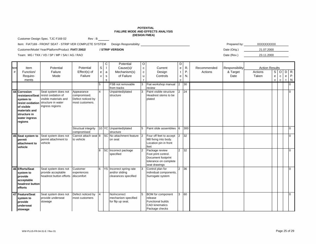
44 Corrosion
resistance/Seat
system to
resist oxidation
of visible
materials and
structure in
water ingress
regions
Seat system does not
resist oxidation of
visible materials and
structure in water
ingress regions
Appearance
compromised.
Defect noticed by
most customers.
4 Unpainted/plated
structure
3 Paint visible structure
Headrest stems to be
plated
2 24 0
Structual integrity
compromised
10 YC Unpainted/plated
structure
5 Paint slide assemblies 6 300 0
45 Seat system to
permit
attachment to
vehicle
Seat system does not
permit attachment to
vehicle
Cannot attach seat
to vehicle
8 SC No attachment feature
on seat
2 Four off feet to accept
M8 fixing into body.
Location pin in front
feet
2 32 0
8 SC Incorrect package
specified
2 Package review
Foot print control.
Document footprint
tolerance on complete
seat drawings
2 32 0
46 Efforts/Seat
system to
provide
acceptable
headrest button
efforts
Seat system does not
provide acceptable
headrest button efforts
Customer
experiences
discomfort
6 YS Incorrect spring rate
and/or sliding
clearances specified
3 Control plan for
individual components,
Surrogate system
2 36 0
47 Feature/Seat
system to
provide
underseat
stowage
Seat system does not
provide underseat
stowage
Defect noticed by
most customers
4 No/incorrect
mechanism specified
for flip up seat.
5 BOM for component
release
Functional builds
CAD kinematics
Package checks
3 60 0
WW-PLUS-FR-04-31-E / Rev 01 Page 25 of 29

POTENTIAL
FAILURE MODE AND EFFECTS ANALYSIS
(DESIGN FMEA)
Customer Design Spec. TJC F169 02 Rev : B
Item: FIAT169 - FRONT SEAT - STRIP VER COMPLETE SYSTEM Design Responsibility: Prepared by: XXXXXXXXXX
Customer/Model Year/Platform/Product: FIAT/ 2002/ / STRIP VERSION Date (Orig.) 21.07.2000
Team: MG / TKK / VD / SP / MP / SAI / AG / RAO Date (Rev.) 23.11.2000
C Potential O D
Item Item Potential Potential S l Cause(s)/ c Current e R. Recommended Responsibility Action Results
# Function/ Failure Effect(s) of e a Mechanism(s) c Design t P. Actions & Target Actions S O D R.
Require- Mode Failure v s of Failure u Controls e N. Date Taken e c e P.
ments s r c v c t N.
4 No stowage box
specified.
3 BOM for component
release
Functional builds
Package checks
3 36 0
WW-PLUS-FR-04-31-E / Rev 01 Page 26 of 29

Process Failure Mode Effects and Analysis (PFMEA) Instructions
NOTE: Process FMEA's must be prepared for all programs (components, subassemblies and assemblies)
where Johnson Controls has full program design responsibility. (A matrix for this purpose and the FMEA
Form can be found in the AIAG APQP and Control Plan manual).
INSTRUCTIONS:
1. Process FMEA's are to be prepared using the DaimlerChrysler, Ford, and General Motors guidelines.
2. All operations affecting fit, function, durability, governmental regulations and safety must be identified and
listed sequentially.
3. Similar part FMEAs must be considered.
4. Historical campaign, warranty data, high mileage and P-diagram data must be reviewed.
5. Appropriate corrective actions must be planned and/or taken for high risk priority items (RPN 70 and
greater).
6. Appropriate corrective actions must be planned and/or taken for high severity numbers (severity of 7 and
greater).
7. Risk priorities numbers must be revised when corrective actions are completed.
8. High severity numbers must be revised when a design change is completed.
9. The effects must consider the customer in terms of the subsequent operation, assembly, and product.
10. Warranty information must be used as an aid in developing the Process FMEA.
11. Customer plant problems must be used as an aid in developing the Process FMEA.
12. The causes must be described in terms of something that can be fixed or controlled.
13. Where detection is the major factor, provisions must be made to control the cause prior to the next
operation.
14. The PFMEA must identify and address all Special Characteristics (both significant and critical).
WW-PLUS-FR-04-31-E / Rev 01 Page 27 of 29

POTENTIAL
FAILURE MODE AND EFFECTS ANALYSIS
(PROCESS FMEA)
FMEA Number:
Item: Process Responsibility: Prepared by:
Model Year(s)/Vehicle(s) __________________________ Key Date Date (Orig.)
Team: Date (Rev.)
C Potential O D
Process Process Potential Potential S l Cause(s)/ c Current e R. Recommended Responsibility Action Results
# Function/ Failure Effect(s) of e a Mechanism(s) c Process t P. Actions & Target Actions S O D R.
Require- Mode Failure v s of Failure u Controls e N. Date Taken e c e P.
ments s r c v c t N.
WW-PLUS-FR-01-31-E / Rev 01 Page 28 of 29

Customer and Internal Special Char. Symbols
<tulip> North American Interiors ~Internal SC symbol
<S> Shield - DaimlerChrysler
<S/C> Safety Compliance - GM
<D> Diamond - DaimlerChrysler
<P> Pentagon - DaimlerChysler
CC or YC Critical Characteristic - Ford
<F/F> Fit/Function - Ford
SC or YS Significant Characteristic
WW-PLUS-FR-01-31-E / Rev 01 Page 29 of 29