Embed Size (px)
Citation preview

F160 VISION SENSOR

2
The F160’s specialized double-speed cameras can capture imagesup to 4 times faster than with previous cameras. In addition, cameras feature 8 user-selectable shutter speeds and an IntelligentLighting Interface. The F160’s high speed processing, inspectionand measurement results are generated 2 to 10 times faster thanbefore. In the Gray Search example image below, inspections can becompleted at a rate of 5,000 inspections per-minute. Because eachinspection is performed at high speed, the total inspection time forcomplex applications is dramatically reduced, leaving time for additional inspections that may not have been possible with previous products. This can lead to significant improvements in production line throughput and product quality.
Simple Gray Search Processing ofone area – 12ms
Gray Search Processing of multipleinspection areas – 11ms
Gray Search Processing of multipleinspection areas with position compensation enabled – 35ms
Creating New Possibilities with High-speed Vision
F160
Existing products
Image capture time Inspection processing time
Up to 4 times as fast 2 to 10 times as fast
The First Vision Sensor to Offer High-speed, Mid-range Machine
Vision PerformanceThe F160 is the industry’s first high-speed vision sensor to deliver mid-range
machine vision performance to meet more demanding vision applications. The F160 enlistshigh speed, two-camera image capture and vision algorithm processing to meet the needs oftoday’s high-speed production lines. The on-screen set up and configura-tion system offers beginners or experts fast and easy set up. A wizard-like prompted menu option helps new users with auto setup routines,while the "expert" menu option lets those with more experience directlyset configuration parameters. Several new and improved algorithms, likeOmron’s Quest OCR and "variable box" technology let users performmore precise and sophisticated applications. By using Flash-RAM memo-ry cards, the memory capacity of the F160 can be expanded to handlemultiple product lines. Choose from a selection of compact cameraoptions to satisfy many inspection and measurement needs. The F160also allows the customization of menus, "results" screen information andsymbol and text colors to ensure optimum on-site operability. Omron'smachine vision technology and know-how has come together to bring anew level of machine vision measurement and inspection capability.

3
ACME
BOX
ACME
BOX
ACME
BOX
ACME
BOX
Product SortingSort boxed product by size or labels and inspect seams.
Camera 0
Trigger sensor F160 Controller
Camera 1
High Speed Bottle Inspection PCB InspectionInspect dimensions, conformance and date code.
Camera 1
Trigger sensor
Camera 0
F160 Controller
Camera 0
Tooling
S.C.A.R.A. Robot I/O and RS-232C/422 position data
Camera 1F160 Controller
Position Reference High Speed Robotic Tool GuidanceIdentify random, odd-shaped product positioning on a conveyor. Communicate tool and part alignment and tool wear to robotics.
Trigger sensor
F160 Controller
I/O and RS-232C/422 position data
Camera
Optical Character RecognitionPill presence/absence and Lot/Date code confirmation on blister packs.
Trigger sensor
F160 Controller
RS-232C/422 label data
Camera
Electronic component inspection/board position measurement.
Trigger sensor
F160 Controller
RS-232C/422 component and position data
Camera
High-speed and Measurement Inspection Applications

4
Advanced Algorithms and Functions
Flexible search allows the use of several reference models for agray scale search. This method allows objects with modestlychanging features and varying shapes to be inspected with onetool.
New and improved visual inspection algorithms are available in the F160. All of the algorithmstake advantage of the high-speed processing and two-camera capability to maximize your visualinspection capability and functionality.
Quest is an Omron original OCR algorithm. No character teachingrequired. Quest has a high level of discrimination between similar charac-ters and adapts to changes in shape andsize. OCR of one character per region.
QUEST OpticalCharacter Recognition
The box measurement region can besetup to change automatically whenperforming Area or Defect inspectionson objects of varying sizes. Thisensures that the optimum measurementregion is always used for inspection.
"Variable Box"Measurements
Omron’s Edge Width measurement functionworks like a caliper tool. Two edges of anobject are detected to sub-pixel accuracy andfrom this the width of the object is calculated.
Advanced Model Search
Objects with unusual shapes (blobs) canbe detected and counted inside a meas-urement region. Detected objects are thensorted according to area or center ofgravity and measurement data for specific labels is output. Counting gears
Labeling
M
S
M SL
L123
Model 1 Model 2 Model 3
The F160 can compensate for an object’sposition by using only the outline or featureof an object or by two reference pointsfrom an object. Setting priorities for thecompensation direction are also possible.
Position Compensation
Expressions using up to 32 inspectionvariables or constants each can be usedto produce judgement or data output.Expressions allow for complex calcula-tions based on inspection data to deter-mine output results.
Result Expressions
Rotation Search can beperformed on an object todetect rotation up to 360º.The F160 performs thismeasurement 10 timesfaster than before and,using angle interpolation,detection angles can be detectedwith a degree of precision.
Rotation Search
Classification
The classification tool is ideally suited for sorting of multiple objects on the same production line. A search is preformed on an image from multiple reference models and the model numberwith the highest correlation is output.
Compensation in the X direction followed bycompensation in the Y direction
Searching in a rotationrange of 360˚ with askipping angle of 5˚
Object Width Measurement

5
User-friendly OperationThe F160 offers many features to increase its ease-of-use and make its operation asconvenient as possible. These features assist in the setup, operation and use of dataand images produced by the F160.
Images of menu settings, measurement screens, and camera imagescan be captured and stored in the memory card. This feature is veryuseful for creating setup and operation documentation.
Up to 35 measurement images can bestored in memory. These storedimages can consist of all images cap-tured or only the failed images. Thestored images can then be used tohelp diagnose production problems.
Increased ImageStorage
The status of the input and output termi-nals can be displayed on-screen. The I/Omonitor can be used for checking wiringwhen setting up or making adjustmentsto the F160.
I/O MonitorFrequently used F160 operations, likeresult display changes, can beassigned to specific console keys.Menus can also be switched at thetouch of a single console button.
Shortcut Keys
Screen Capture
To prevent unauthorized use or changesto the F160, passwords can be set torestrict access to operation levels. Thisfunction will help to improve securityand reduce incorrect operation.
Password Option
POWER
SYNC
Setting screen Documentation on computers
Capture
Memory card
Setup Manual
Procedure1.
2.
3.
Screen text messages can bechanged to best suit theoperating environment.Message position, charactersize and color and back-ground can also be changed.
ManageableScreen Text
Figures such as lines, boxes, circles and crosses can be drawnand positioned on the screen atmeasurement positions or userset coordinates. Text messageand figure colors can be set forbest viewing.
To save time and simplifysetup, menus can bemasked off from view tohelp minimize setup oper-ations. Masking menuscan also help prevent unauthorizeduse of menu operation.
MenuMasking
The output format of RS-232C data can beset to suit control system requirements.Settings include output format, number ofdata digits, field and record separators andzero suppression.
RS-232C OutputFormattingGood product image
Improper product images
On-screen Figuresand Display Colors

6
F160-SLC20
ObjectCamera distance: 15 to 25 mm
Field of vision (20 x 20 mm)
Object
F160-SLC50
Camera distance: 16.5 to 26.5 mm
Field of vision (50 x 50 mm)
13 5
2
4
Coaxial vertical lighting
15
37
26 84
Unique, Intelligent Light Sources (ILS)
Maximize Lighting Control
Sensing Distance & Field of Vision
The Right Lights & Camera For Your Action
Omron’s compact shutter camera is perfect for high-speed inspection applicationsand can be fitted with several different light sources, including those that supportthe Intelligent Light Source specification, depending on the application.
With an Intelligent Light Source camera, the F160’s controller menustake all of the guesswork out of proper lighting. Operators can con-trol the illuminated area and light intensity from the controllermenus. The settings are easily changed without direct adjustment tothe light source. Lighting positioning is stored with other scene dataso operators can change the lighting conditions to match differentoperating environments. Because the settings are numeric data, it ispossible to recreate the lighting conditions from machine to machine.
Field of vision: 20 mmLight intensity can be setseparately to one of 8 levelsfor 5 illuminated areas.
Field of vision: 50 mmLight intensity can be setseparately to one of 8 levelsfor 8 illuminated areas.
Omron’s ILSs and ILS integrated cameras are designed to enhance and simplify your vision applica-tions. The ILSs use a hood shape that reduces external interference, making conditions ideal forhighly accurate inspections. The combination of red and green LEDs also enables the F160 toinspect a wide range of objects. One ILS version offers the ability of adjustable coaxial vertical lighting in addition to the adjustable ring light. The adjustable ring light lets the user adjust bright-ness and light direction based on the application requirements.

7
System Configuration
Camera withIntelligent LightingF160-SLC20
Synchronous Sensor
Programmable Controller
Color LCD MonitorF150-M05L
Memory CardF160-N64S (64 Mbytes)
Camera withIntelligent LightingF160-SLC50
CameraF160-S1
Double-Speed Camera
Monitor
Camera CableF150-VS (3 m, double-speed camera)F160-VSR3 (3 m, F200/F300)F160-VSR4 (3 m, F300-S)
Parallel CableF160-VP
(2 m, loose-wirecable for parallelI/O connectors)
RCA/BNC Video Cablemonitor cable (2 m)
ControllerF160-C10E (NPN input/output)F160-C15E (PNP input/output)
ConsoleF160-KP
Power SupplyRecommended model:OMRON S82K-05024
8
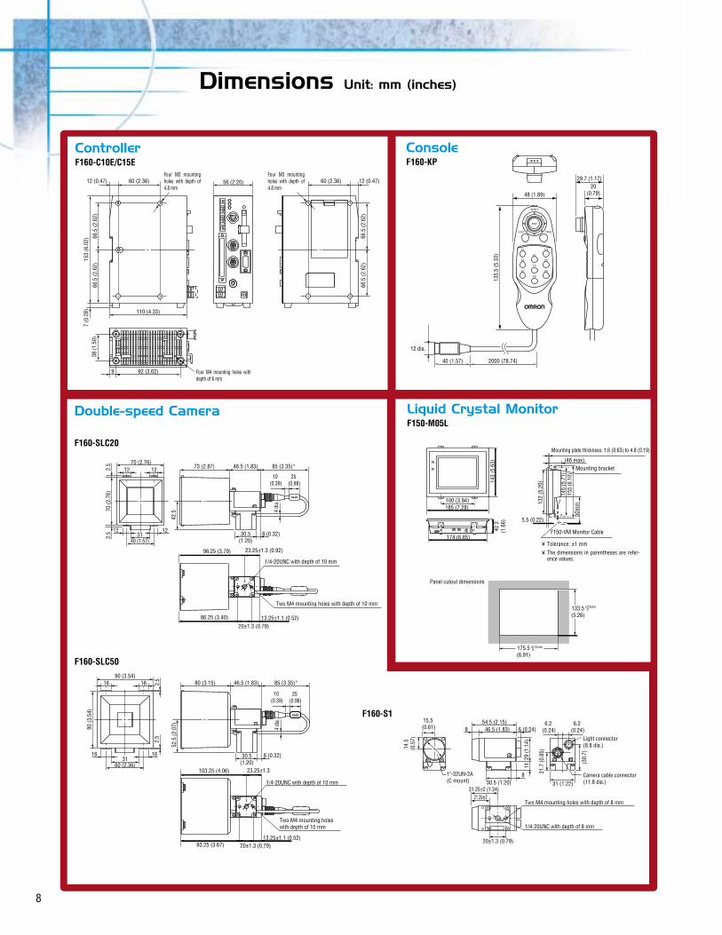
Dimensions Unit: mm (inches)
F160-C10E/C15E F160-KP
38 (1
.50)
7 (0
.28)
153
(6.0
2)
66.5
(2.6
2)66
.5 (2
.62)
66.5
(2.6
2)66
.5 (2
.62)
9 92 (3.62)
110 (4.33)
12 (0.47) 60 (2.36) 56 (2.20) 60 (2.36) 12 (0.47)
SHIFT
ENT
F1
F2
F4
F5
F6
F7
F8
F9
F3
ESC TRIG
135.
5 (5
.33)
48 (1.89)20
(0.79)
29.7 (1.17)
2000 (78.74)40 (1.57)
Controller
Four M3 mounting holes with depth of 4.8 mm
Four M4 mounting holes with depth of 6 mm
Four M3 mounting holes with depth of 4.8 mm
Console
12 dia.
Double-speed Camera
F160-S16.2
(0.24)
(30.
7)
21.7
(0.8
5)
29 (1
.14)
11
6.2 (0.24)
31 (1.22)8
30.5 (1.20)
8 46.5 (1.83)
15.5 (0.61)
54.5 (2.15)6 (0.24)
14.5
(0
.57)
20±1.3 (0.79)
21.25±231.25±2 (1.24)
1"-32UN-2A(C mount)
Light connector (8.8 dia.)
Camera cable connector (11.8 dia.)
Two M4 mounting holes with depth of 8 mm
1/4-20UNC with depth of 8 mm
F160-SLC20
4 di
a.
85 (3.35)*
10 (0.39)
25 (0.98)
10 (0.39)
25 (0.98)
46.5 (1.83)73 (2.87)70 (2.76)
122.5
2.5
70 (2
.76)
42.5
12
12 1230.5
(1.20)8 (0.32)31
40 (1.57)
23.25±1.3 (0.92)
13.25±1.1 (0.52)20±1.3 (0.79)
86.25 (3.40)
96.25 (3.79)
Two M4 mounting holes with depth of 10 mm
1/4-20UNC with depth of 10 mm
90 (3.54)
3160 (2.36)
16
16 16
16 2.5
90 (3
.54)
2.5
52.5
(2.0
7) 4 di
a.
80 (3.15) 46.5 (1.83) 85 (3.35)*
8 (0.32)30.5(1.20)
F160-SLC50
93.25 (3.67)
103.25 (4.06) 23.25±1.3
13.25±1.1 (0.52)20±1.3 (0.79)
Two M4 mounting holes with depth of 10 mm
1/4-20UNC with depth of 10 mm
F150-M05L
POWER
SYNC
143
(5.6
3)
145
(5.7
1)15
5 (6
.10)
132
(5.2
0)
50m
in
(46 max)
100 (3.94)185 (7.28)
5.5 (0.22)
174 (6.85)
42.2
(1.6
6)
133.5(5.26)
175.5(6.91)
+0.5mm 0
+0.5mm 0
Liquid Crystal Monitor
Mounting plate thickness: 1.6 (0.63) to 4.8 (0.19)
Mounting bracket
F150-VM Monitor Cable
Tolerance: ±1 mmThe dimensions in parentheses are refer-ence values.
¥
¥
Panel cutout dimensions

9
SpecificationsRating/FunctionController: F160-C10E/C15E
Item Conversational Menu Mode Expert Menu Mode
Connectable cameras
Number of cameras Connectable
Number of pixels
Number of scenes
F150-S1A/SL20A/SL50A/SLC20/SLC50, F160-S1/SLC20/SLC50, F300-S/S2R/S3DR/S4R etc.
1 2
512 x 484 (H x V)
32 (Expansion possible using Memory Card.)
Image storage function
Filtering
Position displacement compensation
Number of measurement regions
Applications
Maximum of 35 images stored
Smoothing (strong, weak), edge enhancement, edge extraction (horizontal, vertical, both horizontal and vertical), dilation, erosion, median, background suppression
Compensation directions: X, Y, and θ (360°) directionsDetection methods: Binary center of gravity, axis angle, labeling, rotation search, gray search, edge position
Set either automatically or manuallyCompensation directions: X, Y, and θ (360°) directions
32 regions per scene
7 types available (presence, orientation, dimensions, defects, conformity, position, chips and burs)
Automatically selected according to the application.Measurement data
Data operation functions (expressions)
Gravity and area, gravity and axis, gray search, precise search, rotation search, flexible search, relative search, defect, area (variable box), defect (variable box), edge position, edge pitch, edge width, density average, labeling, OCR for 1 character, classification
Number:Operations:
32 expressions can be set for judgements, data, and variables used in other expressionsArithmetic operations, square root, absolute value, remainder, distance, angle, maximum, minimum, SIN, COS, ATAN, AND, OR, NOT
Overall judgements, judgements for each measurement region Overall judgements, judgements for each measurement region, expression results, measurement/expression data
Menu masking, password setting, shortcut keys
1
1 channel (color, monochrome)
RS-232C/422A, 1 channel
13 inputs and 22 outputs including control I/O points
F160-C10E
F160-C15E
20.4 to 26.4 VDC
Approx. 1.6 A (with two F160-SLC50 Cameras connected)
56 x 160 x 110 (W x H x D) mm (not including connectors and other protruding parts)
Approx. 570 g (Controller only)
Results output
Functions for customizing operations
Functions for customizing screens
Number of slots for memory cards
Monitor interface
Serial communications
Parallel I/O
NPNInput/output type PNP
Operating: 0 to 50°C (32 to 122°F) Storage: -25 to 65°C (52 to 149°F) with no icing or condensation
Operating and storage: 35% to 85% (with no condensation)
Power supply voltage
Current consumption
Ambient temperature
Ambient humidity
External dimensions
Weight
Display items:
Specified parameters: Display color, position, size
Character strings (measurement values, judgement results, times, user-specified characters, measurement region names) Figures (lines, boxes, circles, cross cursors)
Double-speed Camera: F160-S1
1/3” Interline CCDPicture element
659 x 494 (H x V)Effective pixels
1/60-s non-interlace (frame) mode, 1/120-s 2:1 interlace (field) modeScanning method
Electronic shutter; select from 8 shutter-speed settings (1/120 to 1/20,000 s) using menu.Shutter
F160-SLC20 (field of vision: 20 mm), F160-SLC50 (field of vision: 50 mm)Camera with intelligent lighting
31 x 40 x 54.5 (W x H x D) mm (not including connectors and other protruding parts)External dimensions
Approx. 85 g (Camera only)Weight
Item
Size
Type
Resolution
Input signals
Power supply voltage
Current consumption
Ambient temperature
Ambient humidity
Weight (monitor only)
Accessories
F150-M05L Color LCD MonitorSpecifications
Item Specifications
5.5 inches; 111.36 x 83.52 mm (H x V)
Liquid crystal color TFT
320 x 240 dots
20.4 to 26.4 VDC
Approx. 700 mA
Operating: 0 to 50°C (32 to 122°F); Storage: -25 to 65°C (52 to 149°F) with no icing or condensation
Operating or storage: 35% to 85% (with no condensation)
Approx. 1 kg
Instruction manual and 4 mounting brackets
NTSC composite video (1.0 V/75 Ω)

10
F160 Vision Sensor Selection Guide
NPN Input/OutputPNP Input/Output
20 mm field of view50 mm field of viewWithout lens or light sourceKeypad with shortcut buttons5.5 inch color LCDMemory capacity: 64 MbytesFor double-speed camera & compatible F150 cameras; Cable length: 3 mFor compatible F200/F300 cameras; Cable length: 3 mFor F300-S only; Cable length: 3 mCable length: 2 mLoose-wire cable for parallel I/O connectors; Cable length: 2 mA set of six extension tubes that are 40, 20, 10, 5, 1, and 0.5 mm in length respectively
F160-C10EF160-C15E
F160-SLC20F160-SLC50F160-S1F160-KPF150-M05LF160-N64SF150-VS
F160-VSR3F160-VSR4RCA/BNC Video CableF160-VPF150-EXT
Controller
Double-speed camera with fixed lens &
intelligent lightingCamera only
ConsoleColor LCD monitor
Memory cardCamera cable
Monitor cableParallel I/O cable
Extension tubes
CommentsModel NumberName
Ordering Information
First: Start by selecting the controller part number with the correct input/output type, NPN or PNP, to meet the applications needs.
Second: Choose from the three F160 double-speed cameras. Select one or two cameras based on the application. If a 20 or 50 mm field of vision can be used with the Intelligent Light Source, choose from the F160-SLC20 or F160-SLC50. (See page 6 for SLC20 & SLC50 setting information.) If different field of view and lighting is required, use the F160-S1 camera without lens and light source.
Third: Choose camera cables, Parallel I/O cable, monitor and monitor cable as required. For additional camera cable and parallel I/O cable lengths and monitor options, please consult your Omron vision representative.
Fourth: If F160-S1 camera option is used, refer to the Lens Selection Guide next to choose a lens for the application. The F160-S1 camera also offers the intelligent lighting interface to allow the use of controllable external lighting options. Please consult your Omron vision representative for additional assistance in lens selection and lighting options.
+ + + +

11
Lens Selection Guide
5,000
3,000
2,000
1,000
500
300
200
100
504 5 10 20 30 50 100 200 300 500
Note: All values are approximate values. It is recommended that the camera distance be adjusted by sliding the camera forward or backward in actual operation.
Camera distance A (mm)
Field of view L (mm)
Optical Graph
t: Extension Tube thickness
Lens model: F150-________
L75L50
L25
L16L12
L8
Field of viewL (mm)
Extension Tube
Lens
Camera
Camera distanceA
(mm)
Unit: mm
30 dia.
Total length
1" -32UN -2A
Max. outer dia.
F150-L829 dia. x 34.5 L*8.0 mmF1.3
F150-L1230 dia. x 34.5 L*12.5 mmF1.4
F150-L1630 dia. x 24.5 L*16.0 mmF1.4
F150-L2530 dia. x 24.5 L*25.0 mmF1.4
F150-L5032 dia. x 37 L*50.0 mmF1.8
F150-L7532 dia. x 42.5 L*75.0 mmF2.7
ModelDimensionsFocal length
Brightness
CCTV Lens
First: Start by defining the field of view requirements for each camera. Refer to the diagram at bottom left. The field of view is considered to be the area or areas requiring inspection. This does not necessarily include the entire part or object in the field of view.
Second: Determine the camera distance, measured from the object surface to the camera. Refer to the lens setting illustration for additional information about setting distance. This distance can impose limitations on the field of view and lens choice. To get the greatest flexibility in lens selection, keep the camera setting distance as flexible as possible.
Third: Using the field of view and camera setting distance requirements, use the optical graph axis marked "Field of view L (mm)" to find the matching field of view size. Use the optical graph axis marked "Camera distance A (mm)" to find the approximate camera setting distance. Follow the values across the chart until they cross. Refer to the lens part reference on the right at the end of the graph line to find the correct lens size. (If a "t" value other than 0 is indicated, corresponding lens extension tubes will need to be added in between the camera and lens in order to properly focus the image. The "t" value indicates the thickness of the extension tubes required.) Note: Extension tube length should not exceed 10% of the focal length of the lens. When looking at other manufacturers’ lenses not referenced by Omron, please use a 1/3-inch CCD size as a selection value reference.
Fourth: If an appropriate lens cannot be found to satisfy your application, please consult your Omron vision representative for additional assistance in lens selection options.
* Lens diameter does not include lens ring lock screw height.
Note: Omron reserves the right to change lens suppliers and specifications without notification. Please verify all lenses with sales personnel.

CANADA REGIONAL SALES OFFICE
UNITED STATES REGIONAL SALES OFFICES
Sao Paulo 55.11.5564.6488BRAZIL SALES OFFICE
Buenos Aires 54.114.787.1129ARGENTINA SALES OFFICE
Florida 954.227.2121MEXICO/LATIN AMERICA SALES OFFICE
800.55.OMRON or 847.843.7900
Toronto 416.286.6465OMRON ELECTRONICS LLCTechnical Automation Solution DivisionSchaumburg, IL
OMRON CANADA, INC.Scarborough, Ontario
2001 OMRON ELECTRONICS LLC
SB F160-1 6/01/7.5M
www.omron.com/oei
Vision Composer SoftwareThis optional Windows®-based Vision Composersoftware allows you to use more sophisticatedfunctionality in a drag-and-drop flow chart environment with the F150-3 Vision Sensor.Vision Composer can also help collect andreport the measurement results without specialized programming.
F-30 Vision SensorCompact, self-contained vision sensor includesthe camera, light source, lens and controller allin one unit. This easy-to-use menu driven bina-ry vision sensor has a 256-level contrast settingand one inspection area that is perfect for mostpixel counting applications.
F-10 Vision SensorThe ultimate, easy-to-use, grayscale process-ing package for pattern and shape matching.Setup is ultra quick with no monitor requiredusing a one button teach function and a visi-ble target, integrated lens and light source.Four different camera choices are available,each with different sensing area sizes. Onemodel even includes 8-model bank memoryand RS-232C/422 communications capability.
F150-3 Vision SensorDelivers 2-camera performance and lighting control based on the F150-2’s easy-to-use for-mat. The camera splitter unit and built-in menusor PC software allows the controller to integrateimages from two cameras and perform multi-angle inspections on a single object simultaneously.
F400 Vision SensorThe industries first color Vision Sensor usingHue, Saturation, and Intensity to combine ColorPickup and 5 color filters into an easy-to-useand powerful color vision solution at an afford-able price. With Color Pickup, the F400 can bequickly configured to detect and measure up to8 colors simultaneously or use the industry’sfirst Colorgray filter to convert a color into 256level grayscale to analyze and measure very finedifferences in the isolated color’s image, even influctuating lighting conditions.
F150-2 Vision SensorUses drop down menus to setup functionsincluding filtering, adjusting the shutter speed,background suppression, X, Y, and Theta posi-tion compensation, and image calibration.Measurement tools include center of gravity,area, edge position, edge pitch, degree ofdefect, and more with 16 setup scenes and upto 16 measurements per scene. Other featuresinclude a 23-image storage memory, RS-232Cand DeviceNet communications.
Vision Sensors and Support Software Solve Your Toughest Inspection Problems