Embed Size (px)
Citation preview
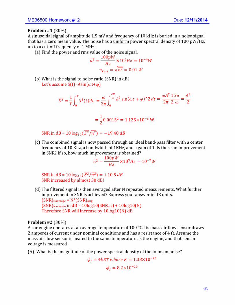
ME36500 Homework #12 Due: 12/11/2014
1/3
Problem #1 (30%) A sinusoidal signal of amplitude 1.5 mV and frequency of 10 kHz is buried in a noise signal that has a zero mean value. The noise has a uniform power spectral density of 100 pW/Hz, up to a cut-‐off frequency of 1 MHz.
(a) Find the power and rms value of the noise signal.
𝑛! =100𝑝𝑊𝐻𝑧 ×10!𝐻𝑧 = 10!!𝑊
𝑛!"# = 𝑛! = 0.01 𝑊 (b) What is the signal to noise ratio (SNR) in dB?
Let’s assume S(t)=Asin(ωt+φ)
𝑆! =1𝑇 𝑆! 𝑡 𝑑𝑡
!
!=𝜔2𝜋
𝐴! sin 𝜔𝑡 + 𝜑 ^2𝑑𝑡 =𝜔𝐴!
2𝜋122𝜋𝜔 =
𝐴!
2
!!!
!
=12 0.0015
! = 1.125×10!! W SNR in dB = 10 log!"( 𝑆!/𝑛!) = −19.48 𝑑𝐵
(c) The combined signal is now passed through an ideal band-‐pass filter with a center
frequency of 10 Khz, a bandwidth of 1KHz, and a gain of 1. Is there an improvement in SNR? If so, how much improvement is obtained?
𝑛! =100𝑝𝑊𝐻𝑧 ×10!𝐻𝑧 = 10!!𝑊
SNR in dB = 10 log!"( 𝑆!/𝑛!) = +10.5 𝑑𝐵 SNR increased by almost 30 dB!
(d) The filtered signal is then averaged after N repeated measurements. What further
improvement in SNR is achieved? Express your answer in dB units. (SNR)Naverage = N*(SNR)orig (SNR)Naverage in dB = 10log10(SNRorg) + 10log10(N) Therefore SNR will increase by 10log10(N) dB
Problem #2 (30%) A car engine operates at an average temperature of 100 °C. Its mass air flow sensor draws 2 amperes of current under nominal conditions and has a resistance of 4 Ω. Assume the mass air flow sensor is heated to the same temperature as the engine, and that sensor voltage is measured.
(A) What is the magnitude of the power spectral density of the Johnson noise?
𝜙! = 4𝑘𝑅𝑇 𝑤ℎ𝑒𝑟𝑒 𝐾 = 1.38×10!!"
𝜙! = 8.2×10!!"
ME36500 Homework #12 Due: 12/11/2014
2/3
(B) What is the magnitude of the power spectral density of the Shot noise?
𝜙! = 2𝐼𝑞𝑅! 𝑤ℎ𝑒𝑟𝑒 𝑞 = 1.6×10!!"
𝜙! = 1.0×10!!" (C) Find the maximum allowable cutoff frequency (𝑓!) for an ideal low pass filter that will
reduce the total power of Johnson and Shot noise below 1×10!!" 𝑊. Assume the low pass filter is characterized by 𝑇 2𝜋𝑓 = 1 𝑖𝑓 𝑓 ≤ 𝑓! and 𝑇 2𝜋𝑓 = 0 𝑖𝑓 𝑓 ≥ 𝑓! . Total noise is 𝜙!"# = 𝜙! + 𝜙! ≈ 𝜙! Using the low pass filter
𝑊!"! = 𝜙!𝑑𝑓 = 1.0×10!!"𝑓! = 1×10!!"!!
!
𝑠𝑜 𝑓! = 1000 𝐻𝑧
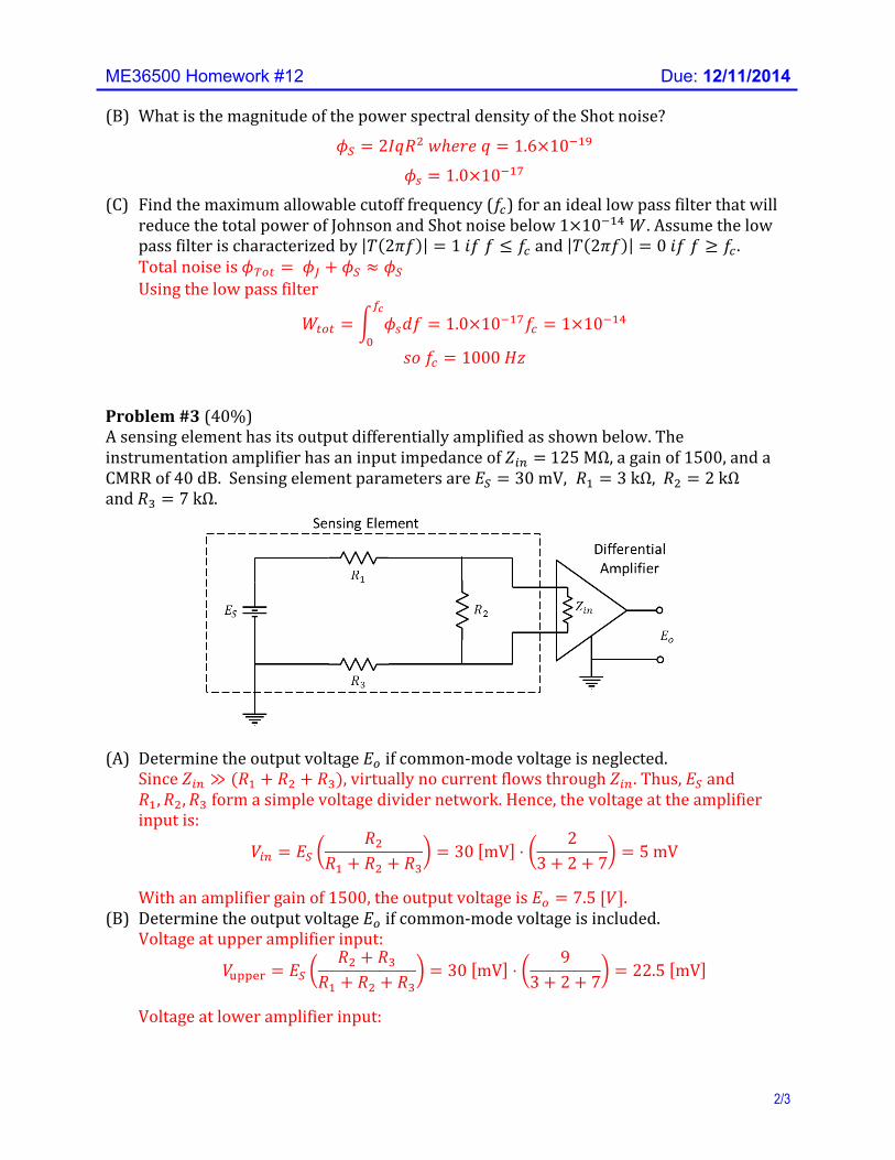
Problem #3 (40%) A sensing element has its output differentially amplified as shown below. The instrumentation amplifier has an input impedance of 𝑍!" = 125 MΩ, a gain of 1500, and a CMRR of 40 dB. Sensing element parameters are 𝐸! = 30 mV, 𝑅! = 3 kΩ, 𝑅! = 2 kΩ and 𝑅! = 7 kΩ.
(A) Determine the output voltage 𝐸! if common-‐mode voltage is neglected.
Since 𝑍!" ≫ (𝑅! + 𝑅! + 𝑅!), virtually no current flows through 𝑍!". Thus, 𝐸! and 𝑅!,𝑅!,𝑅! form a simple voltage divider network. Hence, the voltage at the amplifier input is:
𝑉!" = 𝐸!𝑅!
𝑅! + 𝑅! + 𝑅!= 30 mV ⋅
23+ 2+ 7 = 5 mV
With an amplifier gain of 1500, the output voltage is 𝐸! = 7.5 [𝑉].
(B) Determine the output voltage 𝐸! if common-‐mode voltage is included. Voltage at upper amplifier input:
𝑉!""#$ = 𝐸!𝑅! + 𝑅!
𝑅! + 𝑅! + 𝑅!= 30 mV ⋅
93+ 2+ 7 = 22.5 mV
Voltage at lower amplifier input:
ME36500 Homework #12 Due: 12/11/2014
3/3
𝑉!"#$% = 𝐸!𝑅!
𝑅! + 𝑅! + 𝑅!= 30 mV ⋅
73+ 2+ 7 = 17.5 [mV]
Hence, common-‐mode voltage is 𝑉!"#$% = 17.5 [mV]. Since 𝐶𝑀𝑅𝑅 !" = 40 dB, 𝐶𝑀𝑅𝑅 = 10
!"!" = 100. Thus, accounting for the common-‐
mode voltage:
𝐸! = 7.5+ 1500. 0175100 = 7.5+ 0.2625 = 7.7625 [V]
(C) The differential amplifier is used as the first stage of a digital data acquisition system
that employs a ±10 V, 12-‐bit ADC. How many effective bits of error are introduced by the common-‐mode voltage effect? Quantization interval: 𝑄 = 20 [𝑉] 2!" = 4.88 mV Voltage due to common-‐mode interference: 262.5 mV Q intervals spanned by interference: 262.5 mV 4.88 mV = 53.79 Effective bits of error: log! 53.79 = 5.75 ≈ 6 bits

![HW12,Math121A Spring,2004 UCBERKELEY · 2018-10-28 · HW12,Math121A Spring,2004 UCBERKELEY NasserM.Abbasi Spring,2004 CompiledonOctober28,2018at4:43pm [public] Contents 1 chapter15,problem4.12](https://img.pdfslide.us/doc/110x75/5f498e29df53537153674b1a/hw12math121a-spring2004-ucberkeley-2018-10-28-hw12math121a-spring2004-ucberkeley.jpg)

![[XLS] · Web viewF14/3437 F14/3433 F14/3432 F14/3431 F14/3430 F14/3422 F14/3417 F14/3411 F14/3398 F14/3397 F14/3396 F14/3394 F14/3393 F14/3392 F14/3391 F14/3388 F14/3387 F14/3386](https://img.pdfslide.us/doc/110x75/5af067057f8b9ad0618e00da/xls-viewf143437-f143433-f143432-f143431-f143430-f143422-f143417-f143411.jpg)


![BYU TMA201 historiography [f14]](https://img.pdfslide.us/doc/110x75/55a0f5071a28abd44f8b46f4/byu-tma201-historiography-f14.jpg)


