Embed Size (px)
Citation preview
407
F1) Influence of unsteady friction on trap seal depletion. Professor J. A. Swaffield, Drainage Research Group, School of the Built Environment, Heriot Watt University, Edinburgh, Scotland, EH14 4AS. [email protected]
Abstract Trap seal depletion is a severe concern as a route for cross contamination in building drainage and vent systems, as demonstrated by the SARS outbreak in 2003. The accurate prediction of trap seal water surface oscillation is essential if reliable design guidance is to be provided. While in most cases the rate of change of local pressure consequent upon the arrival of air pressure transients at a trap seal termination of a system branch will be sufficiently slow to allow the assumption of a quasi-steady frictional representation of the forces acting on the water column, there will be occasions, for example following a near instantaneous surcharge event, when this will not be the case and it will be necessary to introduce more complex and appropriate models of unsteady friction. This paper draws on the body of research in pressure surge over the past 40 years that has endeavoured to identify suitable unsteady friction models to represent the rapid changes in flow conditions present under transient propagation conditions. Application of these improved models confirms that the method of characteristics simulation available to determine trap seal depletion may be extended to deal effectively with rapid changes in local air pressure. Experimental validation of these historic models is provided together with the results of current experimental research aimed at providing an empirical friction modifier appropriate to trap seal oscillation. Keywords Unsteady friction, trap seal depletion, transient response.
408
1. Introduction The low amplitude air pressure transients propagated within building drainage and vent systems as a natural consequence of system operation interact with the appliance trap seals throughout the network. Incoming air pressure transients result in trap seal displacement and subsequent oscillations that may result in trap seal loss and enhanced risk of cross contamination from the drainage network to habitable space. The identification of depleted and lost trap seals is a major issue that cannot be addressed purely by observation in complex buildings. Swaffield (2005) and Kelly et al (2006) have discussed a non-invasive trap seal depletion detection method based on the introduction of low amplitude air pressure transients. The loss of a trap seal will be identifiable relative to a benchmark profile obtained while the trap was still complete as the dry trap will display a -1 reflection coefficient, effectively an open termination, compared to the +1 coefficient for a full trap, effectively a dead end termination. Kelly et al (2006) presented laboratory and site test data that confirmed the efficacy of the technique. However there were concerns as to the effect of the pulse generation on the integrity of the system - a non-invasive technique should not place the existing traps at risk. Laboratory and subsequent site testing has demonstrated that a sine wave excitation at frequencies around 10Hz will leave the trap seal unaffected and this approach is further discussed by Kelly (2007). Integral to the non-invasive testing methodology are simulations to ensure that the monitoring locations chosen are the most efficient to allow trap seal status to be assessed. Trap seal displacement depends upon the incoming transient and the design of the trap. Seal depth, water mass, diameter, initial level and wall roughness are all factors. A positive step pulse will displace the trap seal and the subsequent removal of this applied pressure will lead to oscillations that may deplete the trap. The simulation of system response must accurately reflect these oscillations. Previous simulation of building drainage response to low amplitude air pressure transient propagation has demonstrated that current trap modelling is sufficiently accurate to deal with the relatively slow changes in applied pressure that normally accompany the changes in system operation represented by appliance discharges where the rise time of the inflow waterflow is measured in seconds, Jack and Swaffield (2004). The introduction of sinusoidal excitation at frequencies up to 10 Hz introduces a more severe test of the current modelling as the rise time of the applied pressure at the trap is reduced, along with the duration of the applied transient. The overall effect would be to reduce the trap seal oscillation, a desired result for the development of a non-invasive technique but one that should be reproducible by the simulation. Low amplitude air pressure transient propagation in drainage systems belongs to a family of unsteady flow conditions solvable via the Method of Characteristics (MoC), first proposed by Lister (1960) and developed over the past 50 years into the industry standard for surge analysis, Wylie and Streeter (1967), Swaffield and Boldy (1993). Frictional representation is described as ‘quasi-steady’ – the steady state friction loss expressions, based on time local conditions, are deemed to apply sufficiently accurately as the transient propagation – following a pump shut down or controlled valve closure –
409
have been ‘slow’ relative to the system pipe period. This was the basis for the simulations supporting current research on building drainage and vent system design. When the rate of change of local conditions becomes rapid an alternative approach is necessary. Historical research has had as its objective the accurate representation of system unsteady frictional losses, most noteworthy the seminal work of Zilke (1968) who investigated unsteady friction during transient propagation through laminar oil flows in relatively small bore pipes. Zilke’s work is particularly interesting as its objective was to improve the accuracy of MoC simulations in laminar flows that may also be appropriate to trap oscillatory flow. Unsteady friction has remained a continuing strand of pressure surge research, Vitkovsky J. et al (2004). The passage of a transient through a fluid flow, or through a network where the flow is initially at rest, induces a local fluid velocity. However subsequent reflections induce further local fluid flow velocity changes so that the transient event for a particular fluid element may well consist of oscillatory motion rather than a continuous new flow velocity. Under these conditions it is not surprising that the steady state frictional loss expressions – based on, for example, the Darcy equation, or for open channels the Manning Coefficient, will not adequately reflect the frictional damping that will inevitably occur. These steady state expressions require that the flow is both steady – invariate with time – and uniform – invariate with distance in the flow direction. Neither of these conditions can be valid for an element of flow under transient conditions. However when the transient rise times are relatively long, in absolute terms or relative to the system pipe periods, it has been accepted that the relative importance of frictional damping can be regarded as a second order effect and the quasi-steady approach has been acceptable. It is likely that the quasi-steady approximations will not be adequate to represent trap seal response to a sinusoidal excitation and this paper will address that issue and demonstrate that acceptable models may be developed based on historical research designed to identify the importance of unsteady friction. 2. Trap seal retention under pulse and sinusoidal excitation The method of characteristics, MoC, representation of the low amplitude air pressure transient propagation in building drainage and vent systems requires that the available characteristic at a system termination be solved with a suitable boundary condition that links air pressure and velocity at the boundary or provides a time dependent representation of air pressure or velocity at the boundary. Air pressure transient propagation in drainage systems is defined by the St Venant equations of continuity and momentum, a pair of quasi-linear hyperbolic partial differential equations amenable to finite difference solution via the Method of Characteristics. Equations 1 to 4 link conditions at a node one time step in the future to current conditions at adjacent upstream and downstream nodes, Figure 1.
410
For the C+ characteristic : ( )u u c c f u u tDP R P R R R R− +
−− + =2
14
20
γ| | Δ (1)
when dxdt
u c= + (2)
and the C- characteristic : ( )u u c c f u u tDP S P S S S S− −
−− + =2
14
20
γ| | Δ (3)
when dxdt
u c= − (4)
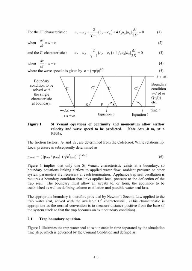
where the wave speed c is given by c = ( γp/ρ)0.5 (5) Figure 1. St Venant equations of continuity and momentum allow airflow
velocity and wave speed to be predicted. Note Δx<1.0 m, Δt < 0.003s.
The friction factors, Rf and Sf , are determined from the Colebrook White relationship. Local pressure is subsequently determined as plocal = [ (patm / ρatm) ( γ/c2
local)γ ]1/(1-γ) (6) Figure 1 implies that only one St Venant characteristic exists at a boundary, so boundary equations linking airflow to applied water flow, ambient pressure or other system parameters are necessary at each termination. Appliance trap seal oscillation is requires a boundary condition that links applied local pressure to the deflection of the trap seal. The boundary must allow an airpath to, or from, the appliance to be established as well as defining column oscillation and possible water seal loss. The appropriate boundary is therefore provided by Newton’s Second Law applied to the trap water seal, solved with the available C+ characteristic. (This characteristic is appropriate as the normal convention is to measure distance positive from the base of the system stack so that the trap becomes an exit boundary condition). 2.1 Trap boundary equation. Figure 1 illustrates the trap water seal at two instants in time separated by the simulation time step, which is governed by the Courant Condition and defined as
Boundary condition v=f(p) or Q=f(t) etc.
time, t
C- C- C+C+
xΔx +ve Equation 3 Equation 1
tt Δ+Boundary
condition to be solved with the single
characteristic at boundary. R P S
411
( )cuxt
+Δ=Δ (1)
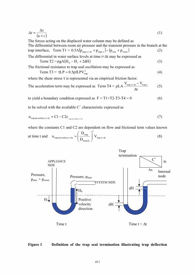
The forces acting on the displaced water column may be defined as The differential between room air pressure and the transient pressure in the branch at the trap interface, Term T1 = ( ) ( )roomatmt,pipett,pipe ppppA5.0 +−+Δ+ (2) The differential in water surface levels at time t+Δt may be expressed as
Term T2 = ( )dH2HHgA 10 +−ρ (3) The frictional resistance to trap seal oscillation may be expressed as Term T3 = 2
trapfLPV5.0LP ρ=τ (4) where the shear stress τ is represented via an empirical friction factor.
The acceleration term may be expressed as Term T4 = t
VVLA t,traptt,trap
Δ−
ρ Δ+ (5)
to yield a boundary condition expressed as F = T1+T2-T3-T4 = 0 (6) to be solved with the available C+ characteristic expressed as
tt,eerfaceinttrapc2C1Cu tt,eerfaceinttrap Δ+
−=Δ+ (7) where the constants C1 and C2 are dependent on flow and frictional term values known
at time t and tt,trap
2
branch
traptt,eerfaceinttrap V
DD
u Δ+Δ+ ⎟⎟⎠
⎞⎜⎜⎝
⎛= (8)
Figure 1 Definition of the trap seal termination illustrating trap deflection
SYSTEM SIDE
APPLIANCESIDE
H1
H0
Pressure, patm + proom
Pressure, ppipe
Positive velocity direction.
dH
dH
Time t Time t + Δt
Δx
Δt
Trap termination
Internal node
C+
412
across a time step. Note trap diameter, D, wetted perimeter P and trap seal water length L Solution may be achieved via the bisection method applied to the function F= T1+T2-T3-T4 between suitable air pressure limits. The C+ is included via Term 4 once the wave speed has been determined from the assumed trial air pressure, pX as
γ
⎟⎟⎠
⎞⎜⎜⎝
⎛ρ
γ=
Δ+ 1
atm
Xatm
X
pp
pc
tt,eerfaceinttrap (9)
2.2 Representation of the friction term. Trap seal oscillation may be identified as laminar based on Reynolds Number, Re, with the friction factor in Term 3 represented by the steady flow laminar friction relationship
trraptrapDV16
Re16f υ== (10)
The flow conditions in the trap are not steady as the water column oscillates in response to system air pressure and a damped oscillation will follow cessation of the transient pressure propagation. A study of trap seal response suggests that steady state friction severely underestimates the frictional forces acting on the oscillating column due to the rapid reversal of flow direction inherent in its oscillation. There is a requirement to include the local flow acceleration in the derivation of an appropriate friction term. Unsteady friction has been a constituent of mainstream pressure surge research for 40 years so that an enhanced frictional model may be developed from this previous work. The earliest and simplest model to include unsteady flow in a frictional representation was due to Daily et al (1956) and Carstens and Roller (1959) who developed an additional empirical term to be added to the friction factor,
tV
VD449.0ff 2steadyunsteady ∂
∂+= (11)
with frictional loss defined by D2
LVfp2ρ=Δ
Abreu and Almeida (2000) comment that this model is limited due to its neglect of a time evolution for the unsteady flow, however it has the advantage of being simple to introduce into a MoC simulation with no major increase in computational time. Vitkovsky et al (2004) present a review of later methods developed to represent unsteady friction in both laminar and turbulent flows. In the case of laminar flows the seminal work of Zilke (1968) is recognised as the basis of all later unsteady frictional research. Zilke defined the terms necessary to include the time evolution of unsteady flow in the friction term to be implemented within a MoC simulation. The Zilke
413
solution considers two dimensional axi-symmetric laminar flow, representing the secondary internal flows induced during the passage of a transient through a convolution of a weighting function and cumulative previous fluid accelerations
( ) **0
t
0 *2
2
dtttWtV
DL16
D2LVfp −
∂∂ρ+ρ=Δ ∫ (12)
where t* is non-dimensional time, 2*
Dt4t υ= (13)
and W is a weighting factor developed by Zilke. The Zilke model includes the two-dimensional pressure and flow gradients present within the unsteady flow. The weighting factors, W, were derived by assuming a constant kinematic viscosity across the pipe that remained unaffected by the passage of the transient and may be determined from the following coefficients.
( ) ( ) j2j
*6
1jj
* tmtW−
=∑= for 02.0t* ≤
( ) ∑=
−=5
1j
tn* *jetW for 02.0t* ⟩
mj = 0.282095, -1.25, 1.057855, 0.396696, -0.351563, j=1,6 nj = 26.3744, 70.8493, 218.9216, 322.5544, j=1,5 Vitkovsky et al review later work to extend Zilke’s model to turbulent flows and introduce various simplifications to reduce the time consuming determination of the frictional terms. They state that the Zilke integral may be approximated by using the rectangular rule and the acceleration term may be approximated using a central finite difference representation
( ) ( )[ ] ( )( )tjtWttjtimeVttjtimeVD
L16D2
LVfp *M
5,3,12
2
ΔΔ−Δ−−Δ+Δ−ρ+ρ=Δ ∑ (14)
where M = time/Δt -1 and ‘time’ is the current calculation time, referred to as t+Δt in Figure 1. This is similar to the Carstens and Roller expression in that it includes the steady state frictional loss along with a term dependent on the flow local accelerations and the time history of the flow – the latter missing from the earlier expression. Expansion of the summation in equation (14) yields a series of one unknown term based on local velocity at time t+Δt and M/2 terms based on historic values of local velocity.
( ) ( )[ ] ( )[ ] ( ) ( )[ ] ( )[ ] 3j1j2
2
t3Wt3tVttVtWtVttVD
L16D2
LVfp == ΔΔ−−Δ−+Δ−Δ+ρ+ρ=Δ ∑ (15)
In equation (15) the summation is only illustrated for j=1,3. In terms of the solution the known terms at j=3 onwards would be calculated once at each time step. The summed truncated series would then be added to term T3 in equation (6). The number of terms included in the summation increases with time. If the simulation time step is 0.001 and
414
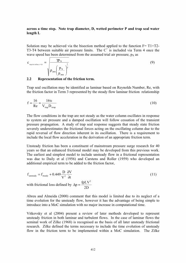
if the simulation runs for 60 seconds then the maximum number of terms included in the summation per node will increase to 0.5*60*103. In this application only one node is affected – the trap termination. However the arguments for an improved frictional representation also apply to every node in the network, with the obvious difference that the fluid would be air. If a typical application considered a 20 storey building with branches on each floor the total pipe length involved could be in excess of 100 m and if the internodal distance used was as low as 100 mm, a typical value then over 60 seconds the maximum number of terms summed across the network would increase 1000 fold to 0.5*60*106. 3. Trap displacement modelling via AIRNET for a pulse excitation Swaffield (2005) and Kelly et al (2006) defined a method to identify depleted trap seals by introducing a low amplitude air pressure pulse and monitoring the form of the recorded pressure trace relative to the status of the trap. Figure 2 illustrates laboratory equipment used to develop the technique while Figure 3 illustrates a typical AIRNET simulation a test where the piston generates a positive pressure transient that propagates along the system and displaces seal water into the appliance side of the trap.
Figure 2 Trial installation to demonstrate the efficacy of depleted trap seal identification based on the application of a single pulse to the network.
Piston, Pipe 1
Pipe 2
Pipe 3
Pipe 5
Pipe 4
Trap termination pipe 4
Pipe Length Diameter Number m mm 1 0.5 150 2 5.5 100 3 6.0 75 4 1.0 50 5 42.0 75
Trap dimensions Diameter 38 mm, Trap seal 100 mm, Centreline radius of U bend 125 mm
Open termination
415
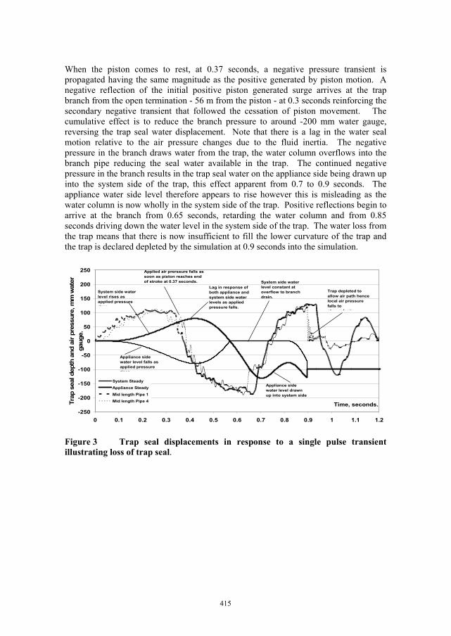
When the piston comes to rest, at 0.37 seconds, a negative pressure transient is propagated having the same magnitude as the positive generated by piston motion. A negative reflection of the initial positive piston generated surge arrives at the trap branch from the open termination - 56 m from the piston - at 0.3 seconds reinforcing the secondary negative transient that followed the cessation of piston movement. The cumulative effect is to reduce the branch pressure to around -200 mm water gauge, reversing the trap seal water displacement. Note that there is a lag in the water seal motion relative to the air pressure changes due to the fluid inertia. The negative pressure in the branch draws water from the trap, the water column overflows into the branch pipe reducing the seal water available in the trap. The continued negative pressure in the branch results in the trap seal water on the appliance side being drawn up into the system side of the trap, this effect apparent from 0.7 to 0.9 seconds. The appliance water side level therefore appears to rise however this is misleading as the water column is now wholly in the system side of the trap. Positive reflections begin to arrive at the branch from 0.65 seconds, retarding the water column and from 0.85 seconds driving down the water level in the system side of the trap. The water loss from the trap means that there is now insufficient to fill the lower curvature of the trap and the trap is declared depleted by the simulation at 0.9 seconds into the simulation.
-250
-200
-150
-100
-50
0
50
100
150
200
250
0 0.1 0.2 0.3 0.4 0.5 0.6 0.7 0.8 0.9 1 1.1 1.2
Time, seconds.Trap
sea
l dep
th a
nd a
ir pr
essu
re, m
m w
ater
ga
uge.
System Steady
Appliance Steady
Mid length Pipe 1Mid length Pipe 4
Appliance side water level falls as applied pressure rises
System side water level rises as applied pressure rises
Lag in response of both appliance and system side water levels as applied pressure falls.
Applied air prerssure falls as soon as piston reaches end of stroke at 0.37 seconds. System side water
level constant at overflow to branch drain.
Appliance side water level drawn up into system side
Trap depleted to allow air path hence local air pressure falls to atmospheric
Figure 3 Trap seal displacements in response to a single pulse transient illustrating loss of trap seal.
416
-150
-100
-50
0
50
100
150
0 0.5 1 1.5 2 2.5 3
Time seconds
Tra
p se
al d
ispl
acem
ent,
mm
wat
er gau
ge
System Side Carstens Zilke Friction
Appliance Side - Carstens ZilkeFrictionSystem Side Steady Friction
Appliance Side Steady Friction
Note trap seal loss predicted
Note trap seal retention predicted
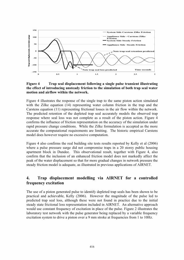
Figure 4 Trap seal displacement following a single pulse transient illustrating the effect of introducing unsteady friction to the simulation of both trap seal water motion and airflow within the network. Figure 4 illustrates the response of the single trap to the same piston action simulated with the Zilke equation (14) representing water column friction in the trap and the Carstens equation (11) representing frictional losses in the air flow within the network. The predicted retention of the depleted trap seal accurately models the observed trap response where seal loss was not complete as a result of the piston action. Figure 4 confirms the influence of friction representation on the accuracy of the simulation under rapid pressure change conditions. While the Zilke formulation is accepted as the more accurate the computational requirements are limiting. The historic empirical Carstens model does however require no excessive computation. Figure 4 also confirms the real building site tests results reported by Kelly et al (2006) where a pulse pressure surge did not compromise traps in a 20 storey public housing apartment block in Dundee. This observational result, together with Figure 4, also confirm that the inclusion of an enhanced friction model does not markedly affect the peak of the water displacement so that for more gradual changes in network pressure the steady friction model is adequate, as illustrated in previous applications of AIRNET. 4. Trap displacement modelling via AIRNET for a controlled frequency excitation The use of a piston generated pulse to identify depleted trap seals has been shown to be practical and achievable, Kelly (2006). However the magnitude of the pulse led to predicted trap seal loss, although these were not found in practice due to the initial steady state frictional loss representation included in AIRNET. An alternative approach would use constant frequency of excitation in place of the pulse. Figure 2 illustrates the laboratory test network with the pulse generator being replaced by a variable frequency excitation system to drive a piston over a 9 mm stroke at frequencies from 1 to 10Hz.
417
-80
-75
-70
-65
-60
-55
-50
-45
-40
-35
-30
0 1 2 3 4 5 6 7 8 9 10
Time, seconds
Tra
p se
al d
ispl
acem
ent,
mm
wat
er g
auge
. System Side Steady Friction Appliance Side Steady Friction
System Side Carstens Zilke Friction Appliance Side Carstens Zilke Friction
1 Hz excitation.
-80
-75
-70
-65
-60
-55
-50
-45
-40
-35
-30
0 1 2 3 4 5 6 7 8 9 10
Time, seconds
Tra
p se
al d
ispl
acem
ent,
mm
wat
er g
auge
System Side Steady Friction Appliance Side Steady Friction
System Side Carstens Zilke Friction Applaince Side Carstens Zilke Friction
10 Hz excitation.
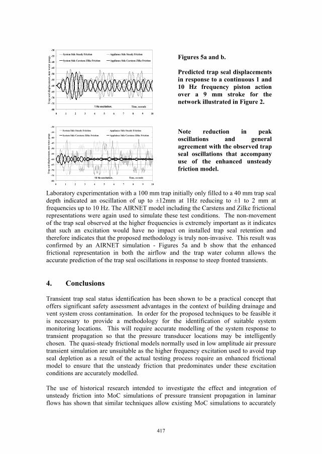
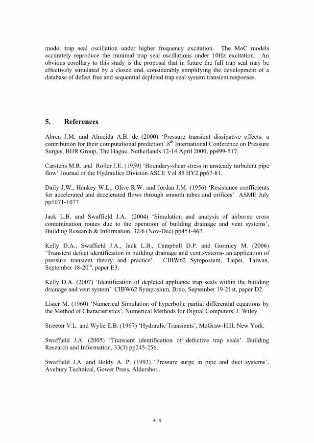
Laboratory experimentation with a 100 mm trap initially only filled to a 40 mm trap seal depth indicated an oscillation of up to ±12mm at 1Hz reducing to ±1 to 2 mm at frequencies up to 10 Hz. The AIRNET model including the Carstens and Zilke frictional representations were again used to simulate these test conditions. The non-movement of the trap seal observed at the higher frequencies is extremely important as it indicates that such an excitation would have no impact on installed trap seal retention and therefore indicates that the proposed methodology is truly non-invasive. This result was confirmed by an AIRNET simulation - Figures 5a and b show that the enhanced frictional representation in both the airflow and the trap water column allows the accurate prediction of the trap seal oscillations in response to steep fronted transients. 4. Conclusions Transient trap seal status identification has been shown to be a practical concept that offers significant safety assessment advantages in the context of building drainage and vent system cross contamination. In order for the proposed techniques to be feasible it is necessary to provide a methodology for the identification of suitable system monitoring locations. This will require accurate modelling of the system response to transient propagation so that the pressure transducer locations may be intelligently chosen. The quasi-steady frictional models normally used in low amplitude air pressure transient simulation are unsuitable as the higher frequency excitation used to avoid trap seal depletion as a result of the actual testing process require an enhanced frictional model to ensure that the unsteady friction that predominates under these excitation conditions are accurately modelled. The use of historical research intended to investigate the effect and integration of unsteady friction into MoC simulations of pressure transient propagation in laminar flows has shown that similar techniques allow existing MoC simulations to accurately
Figures 5a and b. Predicted trap seal displacements in response to a continuous 1 and 10 Hz frequency piston action over a 9 mm stroke for the network illustrated in Figure 2. Note reduction in peak oscillations and general agreement with the observed trap seal oscillations that accompany use of the enhanced unsteady friction model.
418
model trap seal oscillation under higher frequency excitation. The MoC models accurately reproduce the minimal trap seal oscillations under 10Hz excitation. An obvious corollary to this study is the proposal that in future the full trap seal may be effectively simulated by a closed end, considerably simplifying the development of a database of defect free and sequential depleted trap seal system transient responses. 5. References Abreu J.M. and Almeida A.B. de (2000) ‘Pressure transient dissipative effects: a contribution for their computational prediction’.8th International Conference on Pressure Surges, BHR Group, The Hague, Netherlands 12-14 April 2000, pp499-517. Carstens M.R. and Roller J.E. (1959) ‘Boundary-shear stress in unsteady turbulent pipe flow’ Journal of the Hydraulics Division ASCE Vol 85 HY2 pp67-81. Daily J.W., Hankey W.L., Olive R.W. and Jordan J.M. (1956) ‘Resistance coefficients for accelerated and decelerated flows through smooth tubes and orifices’ ASME July pp1071-1077 Jack L.B. and Swaffield J.A.. (2004) ‘Simulation and analysis of airborne cross contamination routes due to the operation of building drainage and vent systems’, Building Research & Information, 32/6 (Nov-Dec) pp451-467. Kelly D.A., Swaffield J.A., Jack L.B., Campbell D.P. and Gormley M. (2006) ‘Transient defect identification in building drainage and vent systems- an application of pressure transient theory and practice’. CIBW62 Symposium, Taipei, Taiwan, September 18-20th, paper E3. Kelly D.A. (2007) ‘Identification of depleted appliance trap seals within the building drainage and vent system’ CIBW62 Symposium, Brno, September 19-21st, paper D2. Lister M. (1960) ‘Numerical Simulation of hyperbolic partial differential equations by the Method of Characteristics’, Numerical Methods for Digital Computers, J. Wiley. Streeter V.L. and Wylie E.B. (1967) ‘Hydraulic Transients’, McGraw-Hill, New York. Swaffield J.A. (2005) ‘Transient identification of defective trap seals’. Building Research and Information, 33(3) pp245-256. Swaffield J.A. and Boldy A. P. (1993) ‘Pressure surge in pipe and duct systems’, Avebury Technical, Gower Press, Aldershot..
419
Vitkovsky J., Stephens M., Bergant A., Lambert M. and Simpson A. (2004) ‘Efficient and accurate calculation of Zilke and Vardy-Brown unsteady friction in pipe transients’. 9th Int. Pressure Surge Conf., BHR Group, Chester UK 24-26 March 2004, pp405-419 Zilke W. (1968) ‘Frequency dependent friction in transient pipe flow’. Journal of Basic Engineering, Trans. ASME, 90(1) pp109-115. Notation A Trap or pipe cross section atm Atmospheric pressure. C+- Characteristic equs. c Wave speed. D Branch or trap dia. dH Trap displacemet. f Friction factor. g Gravitational acc. H Trap water level. L Trap water column length. P Wetted perimeter. p Air pressure. t Time, seconds. u Mean air velocity. V Water velocity. x Distance. γ Ratio specific heats. Δt Time step. Δx Internodal length. ρ Density, kg/m3 τ Shear stress P Unknown conditions at node, t+Δt R,S Known conditions at nodes, time t.
Professor John Swaffield is Head of the School of the Built Environment and leads the Drainage Research Group at Heriot-Watt University. His research interests include water conservation and the development of mathematical simulations of unsteady flows in building drainage and vent systems. He has been involved in drainage and water conservation research, funded by government and industry, for 30 years and has contributed regularly to CIBW62 meetings since 1975.

420