Embed Size (px)
Citation preview
F1: A Fast and Programmable Acceleratorfor Fully Homomorphic Encryption (Extended Version)
Axel Feldmann1∗, Nikola Samardzic1∗, Aleksandar Krastev1, Srini Devadas1,Ron Dreslinski2, Karim Eldefrawy3, Nicholas Genise3, Chris Peikert2, Daniel Sanchez1
1 Massachusetts Institute of Technology 2 University of Michigan{axelf, nsamar, alexalex, devadas, sanchez}@csail.mit.edu {dreslin, cpeikert}@umich.edu
3 SRI International{karim.eldefrawy, nicholas.genise}@sri.com
ABSTRACTFully Homomorphic Encryption (FHE) allows computing on en-crypted data, enabling secure offloading of computation to un-trusted servers. Though it provides ideal security, FHE is expensivewhen executed in software, 4 to 5 orders of magnitude slower thancomputing on unencrypted data. These overheads are a major bar-rier to FHE’s widespread adoption.
We present F1, the first FHE accelerator that is programmable,i.e., capable of executing full FHE programs. F1 builds on an in-depth architectural analysis of the characteristics of FHE compu-tations that reveals acceleration opportunities. F1 is a wide-vectorprocessor with novel functional units deeply specialized to FHEprimitives, such as modular arithmetic, number-theoretic trans-forms, and structured permutations. This organization provides somuch compute throughput that data movement becomes the keybottleneck. Thus, F1 is primarily designed to minimize data move-ment. Hardware provides an explicitly managed memory hierarchyand mechanisms to decouple data movement from execution. Anovel compiler leverages these mechanisms to maximize reuse andschedule off-chip and on-chip data movement.
We evaluate F1 using cycle-accurate simulation and RTL synthe-sis. F1 is the first system to accelerate complete FHE programs, andoutperforms state-of-the-art software implementations by gmean5,400× and by up to 17,000×. These speedups counter most of FHE’soverheads and enable new applications, like real-time private deeplearning in the cloud.
1 INTRODUCTIONDespitemassive efforts to improve the security of computer systems,security breaches are only becoming more frequent and damaging,as more sensitive data is processed in the cloud [43, 69]. Currentencryption technology is of limited help, because servers mustdecrypt data before processing it. Once data is decrypted, it isvulnerable to breaches.
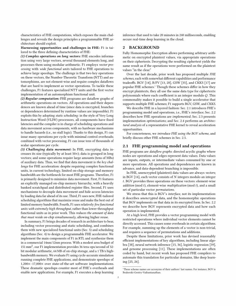
Fully Homomorphic Encryption (FHE) is a class of encryptionschemes that address this problem by enabling generic computationon encrypted data. Fig. 1 shows how FHE enables secure offloadingof computation. The client wants to compute an expensive function𝑓 (e.g., a deep learning inference) on some private data 𝑥 . To do
∗A. Feldmann and N. Samardzic contributed equally to this work.This is an extended version of a paper that will appear in the Proceedings ofthe 54th Annual IEEE/ACM International Symposium on Microarchitecture(MICRO), 2021 [29].
Trus
t bar
rier
Server F1 FHEAccelerator
Encrypted(x)
Encrypted(f(x))Decrypt
Encrypt
f(x)
x1 2 3
45Client
Figure 1: FHE allows a user to securely offload computationto an untrusted server.
this, the client encrypts 𝑥 and sends it to an untrusted server, whichcomputes 𝑓 on this encrypted data directly using FHE, and returnsthe encrypted result to the client. FHE provides ideal security prop-erties: even if the server is compromised, attackers cannot learnanything about the data, as it remains encrypted throughout.
FHE is a young but quickly developing technology. First real-ized in 2009 [33], early FHE schemes were about 109 times slowerthan performing computations on unencrypted data. Since then,improved FHE schemes have greatly reduced these overheads andbroadened its applicability [2, 59]. FHE has inherent limitations—for example, data-dependent branching is impossible, since datais encrypted—so it won’t subsume all computations. Nonetheless,important classes of computations, like deep learning inference [17,25, 26], linear algebra, and other inference and learning tasks [40]are a good fit for FHE. This has sparked significant industry andgovernment investments [4, 9, 23] to widely deploy FHE.
Unfortunately, FHE still carries substantial performance over-heads: despite recent advances [15, 25, 26, 61, 66], FHE is still10,000× to 100,000× slower than unencrypted computation whenexecuted in carefully optimized software. Though this slowdown islarge, it can be addressed with hardware acceleration: if a special-ized FHE accelerator provides large speedups over software execution,it can bridge most of this performance gap and enable new use cases.
For an FHE accelerator to be broadly useful, it should be pro-grammable, i.e., capable of executing arbitrary FHE computations.While prior work has proposed several FHE accelerators, they donot meet this goal. Prior FHE accelerators [20, 21, 27, 65, 66, 71]target individual FHE operations, and miss important ones that theyleave to software. These designs are FPGA-based, so they are smalland miss the data movement issues facing an FHE ASIC accelerator.These designs also overspecialize their functional units to specificparameters, and cannot efficiently handle the range of parametersneeded within a program or across programs.
In this paper we present F1, the first programmable FHE ac-celerator. F1 builds on an in-depth architectural analysis of the
1
arX
iv:2
109.
0537
1v2
[cs
.CR
] 2
5 Se
p 20
21
characteristics of FHE computations, which exposes the main chal-lenges and reveals the design principles a programmable FHE ar-chitecture should exploit.Harnessing opportunities and challenges in FHE: F1 is tai-lored to the three defining characteristics of FHE:(1) Complex operations on long vectors: FHE encodes informa-tion using very large vectors, several thousand elements long, andprocesses them using modular arithmetic. F1 employs vector pro-cessing with wide functional units tailored to FHE operations toachieve large speedups. The challenge is that two key operationson these vectors, the Number-Theoretic Transform (NTT) and au-tomorphisms, are not element-wise and require complex dataflowsthat are hard to implement as vector operations. To tackle thesechallenges, F1 features specialized NTT units and the first vectorimplementation of an automorphism functional unit.(2) Regular computation: FHE programs are dataflow graphs ofarithmetic operations on vectors. All operations and their depen-dences are known ahead of time (since data is encrypted, branchesor dependences determined by runtime values are impossible). F1exploits this by adopting static scheduling: in the style of Very LongInstruction Word (VLIW) processors, all components have fixedlatencies and the compiler is in charge of scheduling operations anddata movement across components, with no hardware mechanismsto handle hazards (i.e., no stall logic). Thanks to this design, F1 canissue many operations per cycle with minimal control overheads;combined with vector processing, F1 can issue tens of thousands ofscalar operations per cycle.(3) Challenging data movement: In FHE, encrypting data in-creases its size (typically by at least 50×); data is grouped in longvectors; and some operations require large amounts (tens of MBs)of auxiliary data. Thus, we find that data movement is the key chal-lenge for FHE acceleration: despite requiring complex functionalunits, in current technology, limited on-chip storage and memorybandwidth are the bottleneck for most FHE programs. Therefore, F1is primarily designed to minimize data movement. First, F1 featuresan explicitly managed on-chip memory hierarchy, with a heavilybanked scratchpad and distributed register files. Second, F1 usesmechanisms to decouple data movement and hide access latenciesby loading data far ahead of its use. Third, F1 uses new, FHE-tailoredscheduling algorithms that maximize reuse andmake the best out oflimited memory bandwidth. Fourth, F1 uses relatively few functionalunits with extremely high throughput, rather than lower-throughputfunctional units as in prior work. This reduces the amount of datathat must reside on-chip simultaneously, allowing higher reuse.
In summary, F1 brings decades of research in architecture to bear,including vector processing and static scheduling, and combinesthem with new specialized functional units (Sec. 5) and schedulingalgorithms (Sec. 4) to design a programmable FHE accelerator. Weimplement the main components of F1 in RTL and synthesize themin a commercial 14nm/12nm process. With a modest area budget of151mm2, our F1 implementation provides 36 tera-ops/second of 32-bit modular arithmetic, 64MB of on-chip storage, and a 1 TB/s high-bandwidthmemory.We evaluate F1 using cycle-accurate simulationrunning complete FHE applications, and demonstrate speedups of1,200×–17,000× over state-of-the-art software implementations.These dramatic speedups counter most of FHE’s overheads andenable new applications. For example, F1 executes a deep learning
inference that used to take 20 minutes in 240 milliseconds, enablingsecure real-time deep learning in the cloud.
2 BACKGROUNDFully Homomorphic Encryption allows performing arbitrary arith-metic on encrypted plaintext values, via appropriate operationson their ciphertexts. Decrypting the resulting ciphertext yields thesame result as if the operations were performed on the plaintextvalues “in the clear.”
Over the last decade, prior work has proposed multiple FHEschemes, eachwith somewhat different capabilities and performancetradeoffs. BGV [14], B/FV [13, 28], GSW [35], and CKKS [17] arepopular FHE schemes.∗ Though these schemes differ in how theyencrypt plaintexts, they all use the same data type for ciphertexts:polynomials where each coefficient is an integer modulo 𝑄 . Thiscommonality makes it possible to build a single accelerator thatsupports multiple FHE schemes; F1 supports BGV, GSW, and CKKS.
We describe FHE in a layered fashion: Sec. 2.1 introduces FHE’sprogramming model and operations, i.e., FHE’s interface; Sec. 2.2describes how FHE operations are implemented; Sec. 2.3 presentsimplementation optimizations; and Sec. 2.4 performs an architec-tural analysis of a representative FHE kernel to reveal accelerationopportunities.
For concreteness, we introduce FHE using the BGV scheme, andbriefly discuss other FHE schemes in Sec. 2.5.
2.1 FHE programming model and operationsFHE programs are dataflow graphs: directed acyclic graphs wherenodes are operations and edges represent data values. Data valuesare inputs, outputs, or intermediate values consumed by one ormore operations. All operations and dependences are known inadvance, and data-dependent branching is impossible.
In FHE, unencrypted (plaintext) data values are always vectors;in BGV [14], each vector consists of 𝑁 integers modulo an integer𝑡 . BGV provides three operations on these vectors: element-wiseaddition (mod 𝑡 ), element-wise multiplication (mod 𝑡 ), and a smallset of particular vector permutations.
We stress that this is BGV’s interface, not its implementation:it describes unencrypted data, and the homomorphic operationsthat BGV implements on that data in its encrypted form. In Sec. 2.2we describe how BGV represents encrypted data and how eachoperation is implemented.
At a high level, FHE provides a vector programming model withrestricted operations where individual vector elements cannot bedirectly accessed. This causes some overheads in certain algorithms.For example, summing up the elements of a vector is non-trivial,and requires a sequence of permutations and additions.
Despite these limitations, prior work has devised reasonablyefficient implementations of key algorithms, including linear alge-bra [38], neural network inference [15, 36], logistic regression [39],and genome processing [11]. These implementations are oftencoded by hand, but recent work has proposed FHE compilers toautomate this translation for particular domains, like deep learn-ing [25, 26].
∗These scheme names are acronyms of their authors’ last names. For instance, BGV isBrakerski-Gentry-Vaikuntanathan.
2
Finally, note that not all data must be encrypted: BGV providesversions of addition and multiplication where one of the operandsis unencrypted. Multiplying by unencrypted data is cheaper, soalgorithms can trade privacy for performance. For example, a deeplearning inference can use encrypted weights and inputs to keepthe model private, or use unencrypted weights, which does notprotect the model but keeps inputs and inferences private [15].
2.2 BGV implementation overviewWe now describe how BGV represents and processes encrypteddata (ciphertexts). The implementation of each computation onciphertext data is called a homomorphic operation. For example,the homomorphic multiplication of two ciphertexts yields anotherciphertext that, when decrypted, is the element-wise multiplicationof the encrypted plaintexts.Data types: BGV encodes each plaintext vector as a polynomialwith 𝑁 coefficients mod 𝑡 . We denote the plaintext space as 𝑅𝑡 , so
𝔞 = 𝑎0 + 𝑎1𝑥 + ... + 𝑎𝑁−1𝑥𝑁−1 ∈ 𝑅𝑡
is a plaintext. Each plaintext is encrypted into a ciphertext con-sisting of two polynomials of 𝑁 integer coefficients modulo some𝑄 ≫ 𝑡 . Each ciphertext polynomial is a member of 𝑅𝑄 .Encryption and decryption: Though encryption and decryptionare performed by the client (so F1 need not accelerate them), theyare useful to understand. In BGV, the secret key is a polynomial𝔰 ∈ 𝑅𝑄 . To encrypt a plaintext 𝔪 ∈ 𝑅𝑡 , one samples a uniformlyrandom 𝔞 ∈ 𝑅𝑄 , an error (or noise) 𝔢 ∈ 𝑅𝑄 with small entries, andcomputes the ciphertext 𝑐𝑡 as
𝑐𝑡 = (𝔞, 𝔟 = 𝔞𝔰 + 𝑡𝔢 +𝔪) .Ciphertext 𝑐𝑡 = (𝔞, 𝔟) is decrypted by recovering 𝔢′ = 𝑡𝔢 +𝔪 =
𝔟 − 𝔞𝔰 mod 𝑄 , and then recovering 𝔪 = 𝔢′ mod 𝑡 . Decryption iscorrect as long as 𝔢′ does not “wrap around” modulo 𝑄 , i.e., itscoefficients have magnitude less than 𝑄/2.
The security of any encryption scheme relies on the ciphertextsnot revealing anything about the value of the plaintext (or the se-cret key). Without adding the noise term 𝔢, the original message𝔪 would be recoverable from 𝑐𝑡 via simple Gaussian elimination.Including the noise term entirely hides the plaintext (under crypto-graphic assumptions) [49].
As we will see, homomorphic operations on ciphertexts increasetheir noise, so we can only perform a limited number of operationsbefore the resulting noise becomes too large and makes decryptionfail. We later describe noise management strategies (Sec. 2.2.2) tokeep this noise bounded and thereby allow unlimited operations.
2.2.1 Homomorphic operations.Homomorphic addition of ciphertexts 𝑐𝑡0 = (𝔞0, 𝔟0) and 𝑐𝑡1 =
(𝔞1, 𝔟1) is done simply by adding their corresponding polynomials:𝑐𝑡add = 𝑐𝑡0 + 𝑐𝑡1 = (𝔞0 + 𝔞1, 𝔟0 + 𝔟1).Homomorphic multiplication requires two steps. First, the fourinput polynomials are multiplied and assembled:
𝑐𝑡× = (𝔩2, 𝔩1, 𝔩0) = (𝔞0𝔞1, 𝔞0𝔟1 + 𝔞1𝔟0, 𝔟0𝔟1) .This 𝑐𝑡× can be seen as a special intermediate ciphertext encryptedunder a different secret key. The second step performs a key-switch-ing operation to produce a ciphertext encrypted under the originalsecret key 𝔰. More specifically, 𝔩2 undergoes this key-switching
process to produce two polynomials (𝔲1, 𝔲0) = KeySwitch(𝔩2). Thefinal output ciphertext is 𝑐𝑡mul = (𝔩1 + 𝔲1, 𝔩0 + 𝔲0).
As we will see later (Sec. 2.4), key-switching is an expensiveoperation that dominates the cost of a multiplication.Homomorphic permutations permute the 𝑁 plaintext values(coefficients) that are encrypted in a ciphertext. Homomorphicpermutations are implemented using automorphisms, which arespecial permutations of the coefficients of the ciphertext polynomi-als. There are 𝑁 automorphisms, denoted 𝜎𝑘 (𝔞) and 𝜎−𝑘 (𝔞) for allpositive odd 𝑘 < 𝑁 . Specifically,
𝜎𝑘 (𝔞) : 𝑎𝑖 → (−1)𝑠𝑎𝑖𝑘 mod 𝑁 for 𝑖 = 0, ..., 𝑁 − 1,
where 𝑠 = 0 if 𝑖𝑘 mod 2𝑁 < 𝑁 , and 𝑠 = 1 otherwise. For example,𝜎5 (𝔞) permutes 𝔞’s coefficients so that 𝑎0 stays at position 0, 𝑎1 goesfrom position 1 to position 5, and so on (these wrap around, e.g.,with 𝑁 = 1024, 𝑎205 goes to position 1, since 205 · 5 mod 1024 = 1).
To perform a homomorphic permutation, we first compute anautomorphism on the ciphertext polynomials: 𝑐𝑡𝜎 = (𝜎𝑘 (𝔞), 𝜎𝑘 (𝔟)).Just as in homomorphic multiplication, 𝑐𝑡𝜎 is encrypted undera different secret key, requiring an expensive key-switch to pro-duce the final output 𝑐𝑡perm = (𝔲1, 𝜎𝑘 (𝔟) + 𝔲0), where (𝔲1, 𝔲0) =KeySwitch(𝜎𝑘 (𝔞)).
We stress that the permutation applied to the ciphertext does notinduce the same permutation on the underlying plaintext vector.For example, using a single automorphism and careful indexing, itis possible to homomorphically rotate the vector of the 𝑁 encryptedplaintext values.
2.2.2 Noise growth and management.Recall that ciphertexts have noise, which limits the number of oper-ations that they can undergo before decryption gives an incorrectresult. Different operations induce different noise growth: additionand permutations cause little growth, but multiplication incursmuch more significant growth. So, to a first order, the amount ofnoise is determined by multiplicative depth, i.e., the longest chainof homomorphic multiplications in the computation.
Noise forces the use of a large ciphertext modulus𝑄 . For example,an FHE programwith multiplicative depth of 16 needs𝑄 to be about512 bits. The noise budget, and thus the tolerable multiplicativedepth, grow linearly with log𝑄 .
FHE uses two noise management techniques in tandem: boot-strapping and modulus switching.Bootstrapping [33] enables FHE computations of unbounded depth.Essentially, it removes noise from a ciphertext without access to thesecret key. This is accomplished by evaluating the decryption func-tion homomorphically. Bootstrapping is an expensive procedurethat consists of many (typically tens to hundreds) homomorphicoperations. FHE programs with a large multiplicative depth can bedivided into regions of limited depth, separated by bootstrappingoperations.
Even with bootstrapping, FHE schemes need a large noise bud-get (i.e., a large 𝑄) because (1) bootstrapping is computationallyexpensive, and a higher noise budget enables less-frequent boot-strapping, and (2) bootstrapping itself consumes a certain noisebudget (this is similar to why pipelining circuits hits a performanceceiling: registers themselves add area and latency).
3
Modulus switching rescales ciphertexts from modulus 𝑄 to amodulus 𝑄 ′, which reduces the noise proportionately. Modulusswitching is usually applied before each homomorphic multiplica-tion, to reduce its noise blowup.
For example, to execute an FHE program of multiplicative depth16, we would start with a 512-bit modulus 𝑄 . Right before eachmultiplication, we would switch to a modulus that is 32 bits shorter.So, for example, operations at depth 8 use a 256-bit modulus. Thus,beyond reducing noise, modulus switching reduces ciphertext sizes,and thus computation cost.
2.2.3 Security and parameters.The dimension 𝑁 and modulus 𝑄 cannot be chosen independently;𝑁 /log𝑄 must be above a certain level for sufficient security. Inpractice, this means that using a wide modulus to support deepprograms also requires a large 𝑁 . For example, with 512-bit 𝑄 ,𝑁 = 16𝐾 is required to provide an acceptable level of security,resulting in very large ciphertexts.
2.3 Algorithmic insights and optimizationsF1 leverages two optimizations developed in prior work:Fast polynomialmultiplication viaNTTs:Multiplying two poly-nomials requires convolving their coefficients, an expensive (naively𝑂 (𝑁 2)) operation. Just like convolutions can be made faster withthe Fast Fourier Transform, polynomial multiplication can be madefaster with the Number-Theoretic Transform (NTT) [54], a variantof the discrete Fourier transform for modular arithmetic. The NTTtakes an 𝑁 -coefficient polynomial as input and returns an 𝑁 -ele-ment vector representing the input in the NTT domain. Polynomialmultiplication can be performed as element-wise multiplication inthe NTT domain. Specifically,
𝑁𝑇𝑇 (𝔞𝔟) = 𝑁𝑇𝑇 (𝔞) ⊙ 𝑁𝑇𝑇 (𝔟),
where ⊙ denotes component-wise multiplication. (For this relationto hold with 𝑁 -point NTTs, a negacyclic NTT [49] must be used(Sec. 5.2).)
Because an NTT requires only 𝑂 (𝑁 log𝑁 ) modular operations,multiplication can be performed in𝑂 (𝑁 log𝑁 ) operations by usingtwo forward NTTs, element-wise multiplication, and an inverseNTT. And in fact, optimized FHE implementations often store poly-nomials in the NTT domain rather than in their coefficient formacross operations, further reducing the number of NTTs. This ispossible because the NTT is a linear transformation, so additionsand automorphisms can also be performed in the NTT domain:
𝑁𝑇𝑇 (𝜎𝑘 (𝔞)) = 𝜎𝑘 (𝑁𝑇𝑇 (𝔞))𝑁𝑇𝑇 (𝔞 + 𝔟) = 𝑁𝑇𝑇 (𝔞) + 𝑁𝑇𝑇 (𝔟)
Avoiding wide arithmetic via Residue Number System (RNS)representation: FHE requires wide ciphertext coefficients (e.g., 512bits), but wide arithmetic is expensive: the cost of a modular multi-plier (which takes most of the compute) grows quadratically withbit width in our range of interest. Moreover, we need to efficientlysupport a broad range of widths (e.g., 64 to 512 bits in 32-bit incre-ments), both because programs need different widths, and becausemodulus switching progressively reduces coefficient widths.
RNS representation [31] enables representing a single polyno-mial with wide coefficients as multiple polynomials with narrower
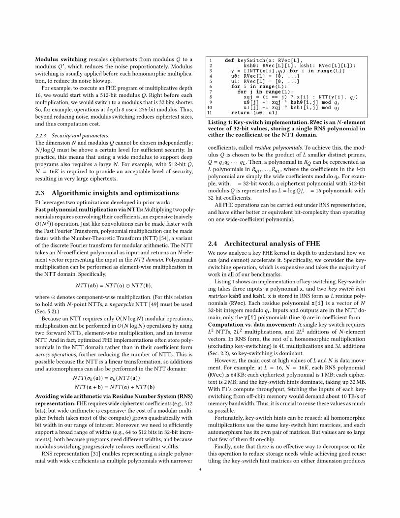
1 def keySwitch(x: RVec[L],2 ksh0: RVec[L][L], ksh1: RVec[L][L]):3 y = [INTT(x[i],𝑞𝑖 ) for i in range(L)]4 u0: RVec[L] = [0, ...]5 u1: RVec[L] = [0, ...]6 for i in range(L):7 for j in range(L):8 xqj = (i == j) ? x[i] : NTT(y[i], 𝑞 𝑗 )9 u0[j] += xqj * ksh0[i,j] mod 𝑞 𝑗
10 u1[j] += xqj * ksh1[i,j] mod 𝑞 𝑗
11 return (u0, u1)
Listing 1: Key-switch implementation. RVec is an 𝑁 -elementvector of 32-bit values, storing a single RNS polynomial ineither the coefficient or the NTT domain.
coefficients, called residue polynomials. To achieve this, the mod-ulus 𝑄 is chosen to be the product of 𝐿 smaller distinct primes,𝑄 = 𝑞1𝑞2 · · · 𝑞𝐿 . Then, a polynomial in 𝑅𝑄 can be represented as𝐿 polynomials in 𝑅𝑞1 , . . . , 𝑅𝑞𝐿 , where the coefficients in the 𝑖-thpolynomial are simply the wide coefficients modulo 𝑞𝑖 . For exam-ple, with𝑊 = 32-bit words, a ciphertext polynomial with 512-bitmodulus 𝑄 is represented as 𝐿 = log𝑄/𝑊 = 16 polynomials with32-bit coefficients.
All FHE operations can be carried out under RNS representation,and have either better or equivalent bit-complexity than operatingon one wide-coefficient polynomial.
2.4 Architectural analysis of FHEWe now analyze a key FHE kernel in depth to understand how wecan (and cannot) accelerate it. Specifically, we consider the key-switching operation, which is expensive and takes the majority ofwork in all of our benchmarks.
Listing 1 shows an implementation of key-switching. Key-switch-ing takes three inputs: a polynomial x, and two key-switch hintmatrices ksh0 and ksh1. x is stored in RNS form as 𝐿 residue poly-nomials (RVec). Each residue polynomial x[i] is a vector of 𝑁32-bit integers modulo 𝑞𝑖 . Inputs and outputs are in the NTT do-main; only the y[i] polynomials (line 3) are in coefficient form.Computation vs. data movement: A single key-switch requires𝐿2 NTTs, 2𝐿2 multiplications, and 2𝐿2 additions of 𝑁 -elementvectors. In RNS form, the rest of a homomorphic multiplication(excluding key-switching) is 4𝐿 multiplications and 3𝐿 additions(Sec. 2.2), so key-switching is dominant.
However, the main cost at high values of 𝐿 and 𝑁 is data move-ment. For example, at 𝐿 = 16, 𝑁 = 16𝐾 , each RNS polynomial(RVec) is 64 KB; each ciphertext polynomial is 1MB; each cipher-text is 2MB; and the key-switch hints dominate, taking up 32MB.With F1’s compute throughput, fetching the inputs of each key-switching from off-chip memory would demand about 10 TB/s ofmemory bandwidth. Thus, it is crucial to reuse these values as muchas possible.
Fortunately, key-switch hints can be reused: all homomorphicmultiplications use the same key-switch hint matrices, and eachautomorphism has its own pair of matrices. But values are so largethat few of them fit on-chip.
Finally, note that there is no effective way to decompose or tilethis operation to reduce storage needs while achieving good reuse:tiling the key-switch hint matrices on either dimension produces
4
many long-lived intermediate values; and tiling across RVec ele-ments is even worse because in NTTs every input element affectsevery output element.Performance requirements: We conclude that, to accommodatethese large operands, an FHE accelerator requires a memory systemthat (1) decouples data movement from computation, as demandmisses during frequent key-switches would tank performance; and(2) implements a large amount of on-chip storage (over 32MB inour example) to allow reuse across entire homomorphic operations(e.g., reusing the same key-switch hints across many homomorphicmultiplications).
Moreover, the FHE accelerator must be designed to use the mem-ory system well. First, scheduling data movement and computationis crucial: data must be fetched far ahead of its use to provide de-coupling, and operations must be ordered carefully to maximizereuse. Second, since values are large, excessive parallelism can in-crease footprint and hinder reuse. Thus, the system should userelatively few high-throughput functional units rather than manylow-throughput ones.Functionality requirements: Programmable FHE acceleratorsmust support a wide range of parameters, both 𝑁 (polynomial/vec-tor sizes) and 𝐿 (number of RNS polynomials, i.e., number of 32-bitprime factors of𝑄). While 𝑁 is generally fixed for a single program,𝐿 changes as modulus switching sheds off polynomials.
Moreover, FHE accelerators must avoid overspecializing in orderto support algorithmic diversity. For instance, we have describedan implementation of key-switching, but there are others [34, 45]with different tradeoffs. For example, an alternative implementationrequires much more compute but has key-switch hints that growwith 𝐿 instead of 𝐿2, so it becomes attractive for very large 𝐿 (∼20).
F1 accelerates primitive operations on large vectors: modular arith-metic, NTTs, and automorphisms. It exploits wide vector processingto achieve very high throughput, even though this makes NTTsand automorphisms costlier. F1 avoids building functional units forcoarser primitives, like key-switching, which would hinder algo-rithmic diversity.Limitations of prior accelerators: Prior work has proposed sev-eral FHE accelerators for FPGAs [20, 21, 27, 52, 53, 65, 66, 71]. Thesesystems have three important limitations. First, they work by accel-erating some primitives but defer others to a general-purpose hostprocessor, and rely on the host processor to sequence operations.This causes excessive data movement that limits speedups. Second,these accelerators build functional units for fixed parameters 𝑁 and𝐿 (or log𝑄 for those not using RNS). Third, many of these systemsbuild overspecialized primitives that limit algorithmic diversity.
Most of these systems achieve limited speedups, about 10× oversoftware baselines. HEAX [65] achieves larger speedups (200× vs.a single core). But it does so by overspecializing: it uses relativelylow-throughput functional units for primitive operations, so toachieve high performance, it builds a fixed-function pipeline forkey-switching.
2.5 FHE schemes other than BGVWe have so far focused on BGV, but other FHE schemes providedifferent tradeoffs. For instance, whereas BGV requires integerplaintexts, CKKS [17] supports “approximate” computation on
Vector RegisterFile (banked)M
emory hierarchy
x128 lanes
NTT
Distributed control
AutomorphismVector functional units
Compute cluster
Mem ctrlMem ctrlMem ctrlMem ctrl
High-Bandwidth Memory
Scratchpadbanks (x16)
On-chip network(3 16x16 crossbars)
Compute clusters(x16)
Mod mult...x x x
...
... ...
Mod mult...x x x
Mod add...+ + +
Mod add...+ + +
...
...
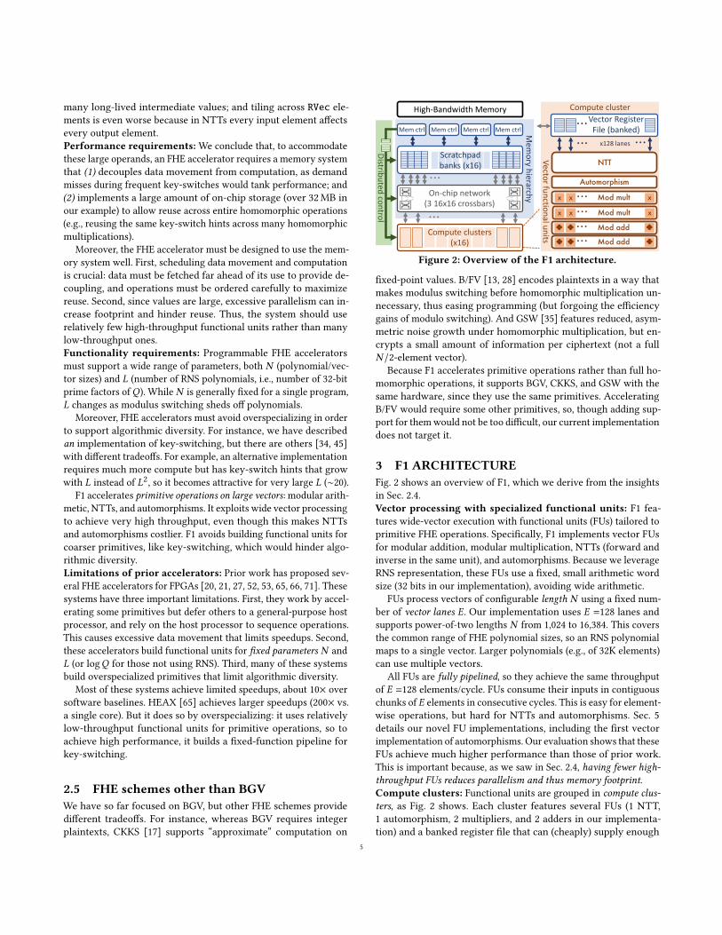
Figure 2: Overview of the F1 architecture.
fixed-point values. B/FV [13, 28] encodes plaintexts in a way thatmakes modulus switching before homomorphic multiplication un-necessary, thus easing programming (but forgoing the efficiencygains of modulo switching). And GSW [35] features reduced, asym-metric noise growth under homomorphic multiplication, but en-crypts a small amount of information per ciphertext (not a full𝑁 /2-element vector).
Because F1 accelerates primitive operations rather than full ho-momorphic operations, it supports BGV, CKKS, and GSW with thesame hardware, since they use the same primitives. AcceleratingB/FV would require some other primitives, so, though adding sup-port for themwould not be too difficult, our current implementationdoes not target it.
3 F1 ARCHITECTUREFig. 2 shows an overview of F1, which we derive from the insightsin Sec. 2.4.Vector processing with specialized functional units: F1 fea-tures wide-vector execution with functional units (FUs) tailored toprimitive FHE operations. Specifically, F1 implements vector FUsfor modular addition, modular multiplication, NTTs (forward andinverse in the same unit), and automorphisms. Because we leverageRNS representation, these FUs use a fixed, small arithmetic wordsize (32 bits in our implementation), avoiding wide arithmetic.
FUs process vectors of configurable length 𝑁 using a fixed num-ber of vector lanes 𝐸. Our implementation uses 𝐸 =128 lanes andsupports power-of-two lengths 𝑁 from 1,024 to 16,384. This coversthe common range of FHE polynomial sizes, so an RNS polynomialmaps to a single vector. Larger polynomials (e.g., of 32K elements)can use multiple vectors.
All FUs are fully pipelined, so they achieve the same throughputof 𝐸 =128 elements/cycle. FUs consume their inputs in contiguouschunks of 𝐸 elements in consecutive cycles. This is easy for element-wise operations, but hard for NTTs and automorphisms. Sec. 5details our novel FU implementations, including the first vectorimplementation of automorphisms. Our evaluation shows that theseFUs achieve much higher performance than those of prior work.This is important because, as we saw in Sec. 2.4, having fewer high-throughput FUs reduces parallelism and thus memory footprint.Compute clusters: Functional units are grouped in compute clus-ters, as Fig. 2 shows. Each cluster features several FUs (1 NTT,1 automorphism, 2 multipliers, and 2 adders in our implementa-tion) and a banked register file that can (cheaply) supply enough
5
operands each cycle to keep all FUs busy. The chip has multipleclusters (16 in our implementation).Memory system: F1 features an explicitly managed memory hier-archy. As Fig. 2 shows, F1 features a large, heavily banked scratch-pad (64MB across 16 banks in our implementation). The scratchpadinterfaces with both high-bandwidth off-chip memory (HBM2 inour implementation) and with compute clusters through an on-chipnetwork.
F1 uses decoupled data orchestration [60] to hide main memorylatency. Scratchpad banks work autonomously, fetching data frommain memory far ahead of its use. Since memory has relativelylow bandwidth, off-chip data is always staged in scratchpads, andcompute clusters do not access main memory directly.
The on-chip network connecting scratchpad banks and computeclusters provides very high bandwidth, which is necessary becauseregister files are small and achieve limited reuse. We implementa single-stage bit-sliced crossbar network [58] that provides fullbisection bandwidth. Banks and the network have wide ports (512bytes), so that a single scratchpad bank can send a vector to acompute unit at the rate it is consumed (and receive it at the rateit is produced). This avoids long staging of vectors at the registerfiles.Static scheduling: Because FHE programs are completely regular,F1 adopts a static, exposed microarchitecture: all components havefixed latencies, which are exposed to the compiler. The compileris responsible for scheduling operations and data transfers in theappropriate cycles to prevent structural or data hazards. This is inthe style of VLIW processors [30].
Static scheduling simplifies logic throughout the chip. For ex-ample, FUs need no stalling logic; register files and scratchpadbanks need no dynamic arbitration to handle conflicts; and theon-chip network uses simple switches that change their configura-tion independently over time, without the buffers and arbiters ofpacket-switched networks.
Because memory accesses do have a variable latency, we assumethe worst-case latency, and buffer data that arrives earlier (note that,because we access large chunks of data, e.g., 64 KB, this worst-caselatency is not far from the average).Distributed control: Though static scheduling is the hallmark ofVLIW, F1’s implementation is quite different: rather than having asingle stream of instructions with many operations each, in F1 eachcomponent has an independent instruction stream. This is possiblebecause F1 does not have any control flow: though FHE programsmay have loops, we unroll them to avoid all branches, and compileprograms into linear sequences of instructions.
This approach may appear costly. But vectors are very long, soeach instruction encodes a lot of work and this overhead is mini-mal. Moreover, this enables a compact instruction format, whichencodes a single operation followed by the number of cycles towait until running the next instruction. This encoding avoids thelow utilization of VLIW instructions, which leave many operationslots empty. Each FU, register file, network switch, scratchpad bank,and memory controller has its own instruction stream, which acontrol unit fetches in small blocks and distributes to components.Overall, instruction fetches consume less than 0.1% of memorytraffic.
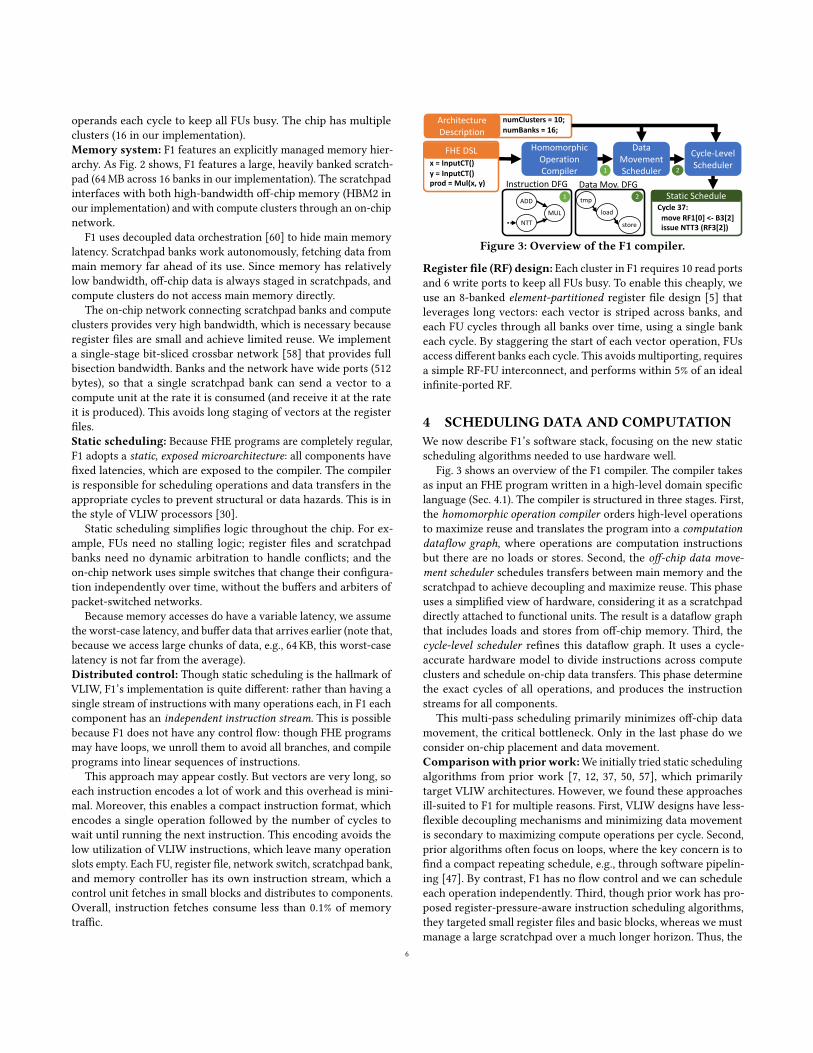
Homomorphic Operation Compiler
Data Movement Scheduler
Cycle-Level Scheduler
Cycle 37:move RF1[0] <- B3[2]issue NTT3 (RF3[2])
Architecture Description
numClusters = 10;numBanks = 16;
Static ScheduleInstruction DFG
1 2x = InputCT()y = InputCT()prod = Mul(x, y)
FHE DSL
Data Mov. DFG
MULNTT
ADD tmp
load
store
1 2
Figure 3: Overview of the F1 compiler.
Register file (RF) design: Each cluster in F1 requires 10 read portsand 6 write ports to keep all FUs busy. To enable this cheaply, weuse an 8-banked element-partitioned register file design [5] thatleverages long vectors: each vector is striped across banks, andeach FU cycles through all banks over time, using a single bankeach cycle. By staggering the start of each vector operation, FUsaccess different banks each cycle. This avoids multiporting, requiresa simple RF-FU interconnect, and performs within 5% of an idealinfinite-ported RF.
4 SCHEDULING DATA AND COMPUTATIONWe now describe F1’s software stack, focusing on the new staticscheduling algorithms needed to use hardware well.
Fig. 3 shows an overview of the F1 compiler. The compiler takesas input an FHE program written in a high-level domain specificlanguage (Sec. 4.1). The compiler is structured in three stages. First,the homomorphic operation compiler orders high-level operationsto maximize reuse and translates the program into a computationdataflow graph, where operations are computation instructionsbut there are no loads or stores. Second, the off-chip data move-ment scheduler schedules transfers between main memory and thescratchpad to achieve decoupling and maximize reuse. This phaseuses a simplified view of hardware, considering it as a scratchpaddirectly attached to functional units. The result is a dataflow graphthat includes loads and stores from off-chip memory. Third, thecycle-level scheduler refines this dataflow graph. It uses a cycle-accurate hardware model to divide instructions across computeclusters and schedule on-chip data transfers. This phase determinethe exact cycles of all operations, and produces the instructionstreams for all components.
This multi-pass scheduling primarily minimizes off-chip datamovement, the critical bottleneck. Only in the last phase do weconsider on-chip placement and data movement.Comparisonwith priorwork:We initially tried static schedulingalgorithms from prior work [7, 12, 37, 50, 57], which primarilytarget VLIW architectures. However, we found these approachesill-suited to F1 for multiple reasons. First, VLIW designs have less-flexible decoupling mechanisms and minimizing data movementis secondary to maximizing compute operations per cycle. Second,prior algorithms often focus on loops, where the key concern is tofind a compact repeating schedule, e.g., through software pipelin-ing [47]. By contrast, F1 has no flow control and we can scheduleeach operation independently. Third, though prior work has pro-posed register-pressure-aware instruction scheduling algorithms,they targeted small register files and basic blocks, whereas we mustmanage a large scratchpad over a much longer horizon. Thus, the
6
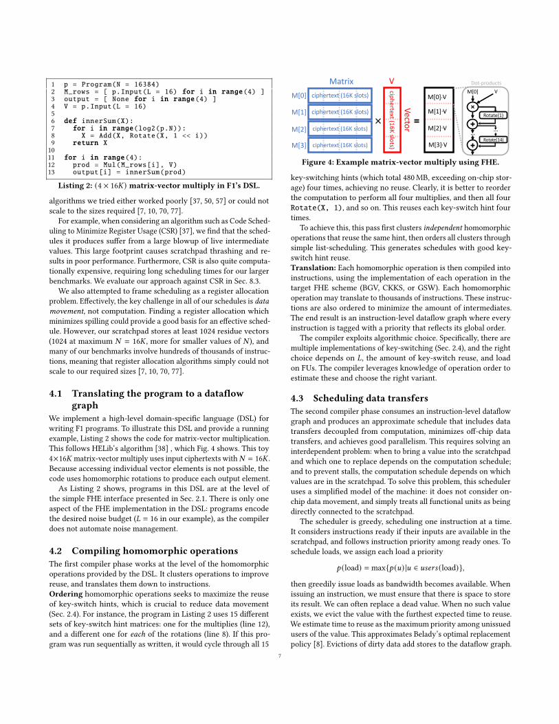
1 p = Program(N = 16384)2 M_rows = [ p.Input(L = 16) for i in range(4) ]3 output = [ None for i in range(4) ]4 V = p.Input(L = 16)56 def innerSum(X):7 for i in range(log2(p.N)):8 X = Add(X, Rotate(X, 1 << i))9 return X1011 for i in range(4):12 prod = Mul(M_rows[i], V)13 output[i] = innerSum(prod)
Listing 2: (4 × 16𝐾) matrix-vector multiply in F1’s DSL.
algorithms we tried either worked poorly [37, 50, 57] or could notscale to the sizes required [7, 10, 70, 77].
For example, when considering an algorithm such as Code Sched-uling to Minimize Register Usage (CSR) [37], we find that the sched-ules it produces suffer from a large blowup of live intermediatevalues. This large footprint causes scratchpad thrashing and re-sults in poor performance. Furthermore, CSR is also quite computa-tionally expensive, requiring long scheduling times for our largerbenchmarks. We evaluate our approach against CSR in Sec. 8.3.
We also attempted to frame scheduling as a register allocationproblem. Effectively, the key challenge in all of our schedules is datamovement, not computation. Finding a register allocation whichminimizes spilling could provide a good basis for an effective sched-ule. However, our scratchpad stores at least 1024 residue vectors(1024 at maximum 𝑁 = 16𝐾 , more for smaller values of 𝑁 ), andmany of our benchmarks involve hundreds of thousands of instruc-tions, meaning that register allocation algorithms simply could notscale to our required sizes [7, 10, 70, 77].
4.1 Translating the program to a dataflowgraph
We implement a high-level domain-specific language (DSL) forwriting F1 programs. To illustrate this DSL and provide a runningexample, Listing 2 shows the code for matrix-vector multiplication.This follows HELib’s algorithm [38] , which Fig. 4 shows. This toy4×16𝐾 matrix-vector multiply uses input ciphertexts with𝑁 = 16𝐾 .Because accessing individual vector elements is not possible, thecode uses homomorphic rotations to produce each output element.
As Listing 2 shows, programs in this DSL are at the level ofthe simple FHE interface presented in Sec. 2.1. There is only oneaspect of the FHE implementation in the DSL: programs encodethe desired noise budget (𝐿 = 16 in our example), as the compilerdoes not automate noise management.
4.2 Compiling homomorphic operationsThe first compiler phase works at the level of the homomorphicoperations provided by the DSL. It clusters operations to improvereuse, and translates them down to instructions.Ordering homomorphic operations seeks to maximize the reuseof key-switch hints, which is crucial to reduce data movement(Sec. 2.4). For instance, the program in Listing 2 uses 15 differentsets of key-switch hint matrices: one for the multiplies (line 12),and a different one for each of the rotations (line 8). If this pro-gram was run sequentially as written, it would cycle through all 15
ciphertext (16K slots)
ciphertext (16K slots)
ciphertext (16K slots)
ciphertext (16K slots)
ciphertext (16K slots)
Matrix
Vector
M[0]
M[1]
M[2]
M[3]
VM[0] V
Rotate(1)
Rotate(14)
Dot-products
M[0] V..
M[1] V..
M[2] V..
M[3] V..
……
Figure 4: Example matrix-vector multiply using FHE.
key-switching hints (which total 480MB, exceeding on-chip stor-age) four times, achieving no reuse. Clearly, it is better to reorderthe computation to perform all four multiplies, and then all fourRotate(X, 1), and so on. This reuses each key-switch hint fourtimes.
To achieve this, this pass first clusters independent homomorphicoperations that reuse the same hint, then orders all clusters throughsimple list-scheduling. This generates schedules with good key-switch hint reuse.Translation: Each homomorphic operation is then compiled intoinstructions, using the implementation of each operation in thetarget FHE scheme (BGV, CKKS, or GSW). Each homomorphicoperation may translate to thousands of instructions. These instruc-tions are also ordered to minimize the amount of intermediates.The end result is an instruction-level dataflow graph where everyinstruction is tagged with a priority that reflects its global order.
The compiler exploits algorithmic choice. Specifically, there aremultiple implementations of key-switching (Sec. 2.4), and the rightchoice depends on 𝐿, the amount of key-switch reuse, and loadon FUs. The compiler leverages knowledge of operation order toestimate these and choose the right variant.
4.3 Scheduling data transfersThe second compiler phase consumes an instruction-level dataflowgraph and produces an approximate schedule that includes datatransfers decoupled from computation, minimizes off-chip datatransfers, and achieves good parallelism. This requires solving aninterdependent problem: when to bring a value into the scratchpadand which one to replace depends on the computation schedule;and to prevent stalls, the computation schedule depends on whichvalues are in the scratchpad. To solve this problem, this scheduleruses a simplified model of the machine: it does not consider on-chip data movement, and simply treats all functional units as beingdirectly connected to the scratchpad.
The scheduler is greedy, scheduling one instruction at a time.It considers instructions ready if their inputs are available in thescratchpad, and follows instruction priority among ready ones. Toschedule loads, we assign each load a priority
𝑝 (load) = max{𝑝 (𝑢) |𝑢 ∈ 𝑢𝑠𝑒𝑟𝑠 (load)},
then greedily issue loads as bandwidth becomes available. Whenissuing an instruction, we must ensure that there is space to storeits result. We can often replace a dead value. When no such valueexists, we evict the value with the furthest expected time to reuse.We estimate time to reuse as the maximum priority among unissuedusers of the value. This approximates Belady’s optimal replacementpolicy [8]. Evictions of dirty data add stores to the dataflow graph.
7
When evicting a value, we add spill (either dirty or clean) and fillinstructions to our dataflow graph.
4.4 Cycle-level schedulingFinally, the cycle-level scheduler takes in the data movement sched-ule produced by the previous phase, and schedules all operationsfor all components considering all resource constraints and data de-pendences. This phase distributes computation across clusters andmanages their register files and all on-chip transfers. Importantly,this scheduler is fully constrained by its input schedule’s off-chipdata movement. It does not add loads or stores in this stage, but itdoes move loads to their earliest possible issue cycle to avoid stallson missing operands. All resource hazards are resolved by stalling.In practice, we find that this separation of scheduling into datamovement and instruction scheduling produces good schedules inreasonable compilation times.
This stage works by iterating through all instructions in theorder produced by the previous compiler phase (Sec. 4.3) and deter-mining the minimum cycle at which all required on-chip resourcesare available. We consider the availability of off-chip bandwidth,scratchpad space, register file space, functional units, and ports.
During this final compiler pass, we finally account for storebandwidth, scheduling stores (which result from spills) as needed.In practice, we find that this does not hurt our performance much,as stores are infrequent across most of our benchmarks due toour global schedule and replacement policy design. After the finalschedule is generated, we validate it by simulating it forward toensure that no clobbers or resource usage violations occur.
It is important to note that because our schedules are fully static,our scheduler also doubles as a performance measurement tool. Asillustrated in Fig. 3, the compiler takes in an architecture descriptionfile detailing a particular configuration of F1. This flexibility allowsus to conduct design space explorations very quickly (Sec. 8.4).
5 FUNCTIONAL UNITSIn this section, we describe F1’s novel functional units. These in-clude the first vectorized automorphism unit (Sec. 5.1), the firstfully-pipelined flexible NTT unit (Sec. 5.2), and a new simplifiedmodular multiplier adapted to FHE (Sec. 5.3).
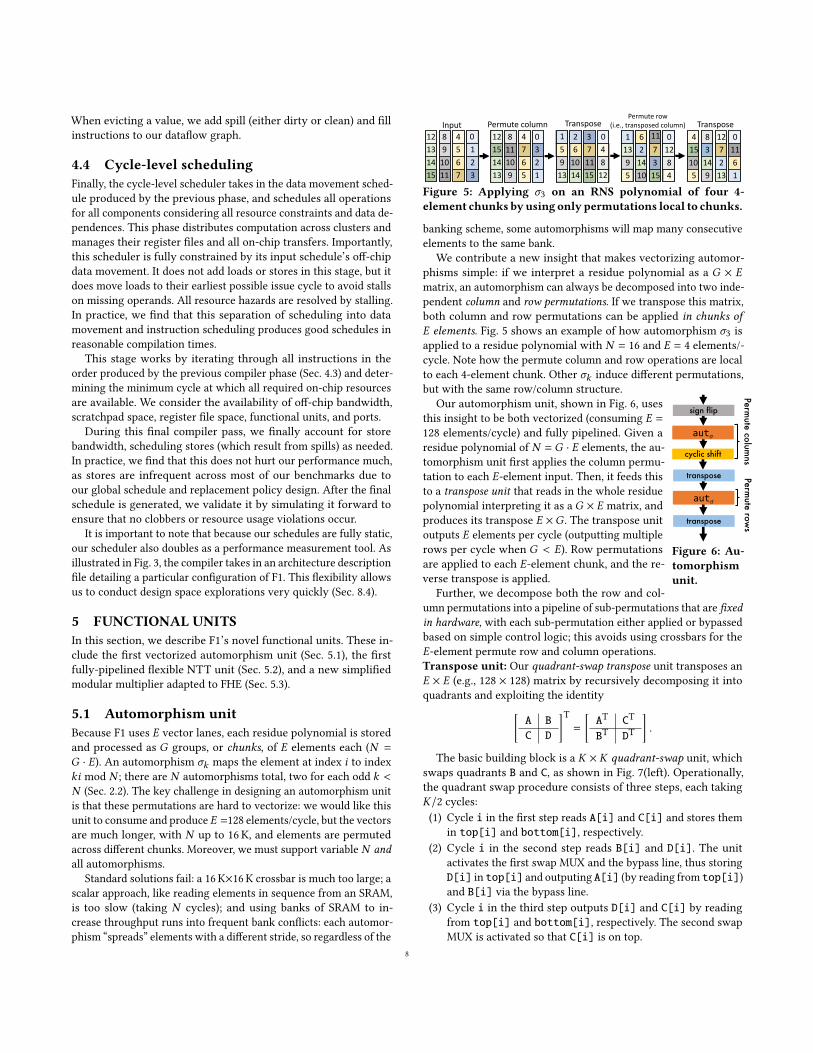
5.1 Automorphism unitBecause F1 uses 𝐸 vector lanes, each residue polynomial is storedand processed as 𝐺 groups, or chunks, of 𝐸 elements each (𝑁 =
𝐺 · 𝐸). An automorphism 𝜎𝑘 maps the element at index 𝑖 to index𝑘𝑖 mod 𝑁 ; there are 𝑁 automorphisms total, two for each odd 𝑘 <
𝑁 (Sec. 2.2). The key challenge in designing an automorphism unitis that these permutations are hard to vectorize: we would like thisunit to consume and produce 𝐸 =128 elements/cycle, but the vectorsare much longer, with 𝑁 up to 16K, and elements are permutedacross different chunks. Moreover, we must support variable 𝑁 andall automorphisms.
Standard solutions fail: a 16 K×16 K crossbar is much too large; ascalar approach, like reading elements in sequence from an SRAM,is too slow (taking 𝑁 cycles); and using banks of SRAM to in-crease throughput runs into frequent bank conflicts: each automor-phism “spreads” elements with a different stride, so regardless of the
Input Permute column Transpose TransposePermute row
(i.e., transposed column)
0123
4567
89
1011
12131415
0321
4765
811109
12151413
048
12
371115
26
1014
159
13
01161
1272
13
83
149
415105
01284
117315
62
1410
11395
Figure 5: Applying 𝜎3 on an RNS polynomial of four 4-element chunks byusing only permutations local to chunks.
banking scheme, some automorphisms will map many consecutiveelements to the same bank.
We contribute a new insight that makes vectorizing automor-phisms simple: if we interpret a residue polynomial as a 𝐺 × 𝐸
matrix, an automorphism can always be decomposed into two inde-pendent column and row permutations. If we transpose this matrix,both column and row permutations can be applied in chunks of𝐸 elements. Fig. 5 shows an example of how automorphism 𝜎3 isapplied to a residue polynomial with 𝑁 = 16 and 𝐸 = 4 elements/-cycle. Note how the permute column and row operations are localto each 4-element chunk. Other 𝜎𝑘 induce different permutations,but with the same row/column structure.
cyclic shift
sign flip
transpose
aut𝜎
Permute colum
nsPerm
ute rows
aut𝜎
transpose
Figure 6: Au-tomorphismunit.
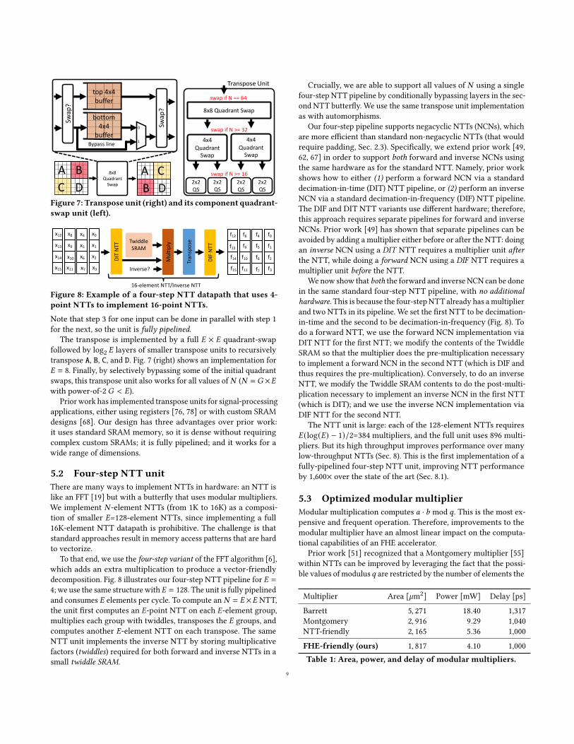
Our automorphism unit, shown in Fig. 6, usesthis insight to be both vectorized (consuming 𝐸 =
128 elements/cycle) and fully pipelined. Given aresidue polynomial of 𝑁 = 𝐺 · 𝐸 elements, the au-tomorphism unit first applies the column permu-tation to each 𝐸-element input. Then, it feeds thisto a transpose unit that reads in the whole residuepolynomial interpreting it as a 𝐺 × 𝐸 matrix, andproduces its transpose 𝐸 ×𝐺 . The transpose unitoutputs 𝐸 elements per cycle (outputting multiplerows per cycle when 𝐺 < 𝐸). Row permutationsare applied to each 𝐸-element chunk, and the re-verse transpose is applied.
Further, we decompose both the row and col-umn permutations into a pipeline of sub-permutations that are fixedin hardware, with each sub-permutation either applied or bypassedbased on simple control logic; this avoids using crossbars for the𝐸-element permute row and column operations.Transpose unit: Our quadrant-swap transpose unit transposes an𝐸 × 𝐸 (e.g., 128 × 128) matrix by recursively decomposing it intoquadrants and exploiting the identity[
A B
C D
]T=
[AT CT
BT DT
].
The basic building block is a 𝐾 × 𝐾 quadrant-swap unit, whichswaps quadrants B and C, as shown in Fig. 7(left). Operationally,the quadrant swap procedure consists of three steps, each taking𝐾/2 cycles:(1) Cycle i in the first step reads A[i] and C[i] and stores them
in top[i] and bottom[i], respectively.(2) Cycle i in the second step reads B[i] and D[i]. The unit
activates the first swap MUX and the bypass line, thus storingD[i] in top[i] and outputing A[i] (by reading from top[i])and B[i] via the bypass line.
(3) Cycle i in the third step outputs D[i] and C[i] by readingfrom top[i] and bottom[i], respectively. The second swapMUX is activated so that C[i] is on top.
8
8x8 Quadrant
Swap
A BDC
A CDB
Swap
?
top 4x4 buffer
bottom 4x4
buffer
Swap
?
1
0
Bypass line
8x8 Quadrant Swap
swap if N == 64
swap if N >= 16
4x4 Quadrant
Swap
2x2 QS
2x2 QS
4x4 Quadrant
Swap
2x2 QS
2x2 QS
swap if N >= 32
Transpose Unit
Figure 7: Transpose unit (right) and its component quadrant-swap unit (left).
Mul
tiply
DIT
NTT
Twiddle SRAM
Tran
spos
e
Inverse?
16-element NTT/Inverse NTT
DIF
NTT
x0
x1
x2
x3
x4
x5
x6
x7
x8
x9
x10
x11
x12
x13
x14
x15
f0
f1
f2
f3
f4
f5
f6
f7
f8
f9
f10
f11
f12
f13
f14
f15
Figure 8: Example of a four-step NTT datapath that uses 4-point NTTs to implement 16-point NTTs.
Note that step 3 for one input can be done in parallel with step 1for the next, so the unit is fully pipelined.
The transpose is implemented by a full 𝐸 × 𝐸 quadrant-swapfollowed by log2 𝐸 layers of smaller transpose units to recursivelytranspose A, B, C, and D. Fig. 7 (right) shows an implementation for𝐸 = 8. Finally, by selectively bypassing some of the initial quadrantswaps, this transpose unit also works for all values of 𝑁 (𝑁 = 𝐺 ×𝐸with power-of-2 𝐺 < 𝐸).
Priorwork has implemented transpose units for signal-processingapplications, either using registers [76, 78] or with custom SRAMdesigns [68]. Our design has three advantages over prior work:it uses standard SRAM memory, so it is dense without requiringcomplex custom SRAMs; it is fully pipelined; and it works for awide range of dimensions.
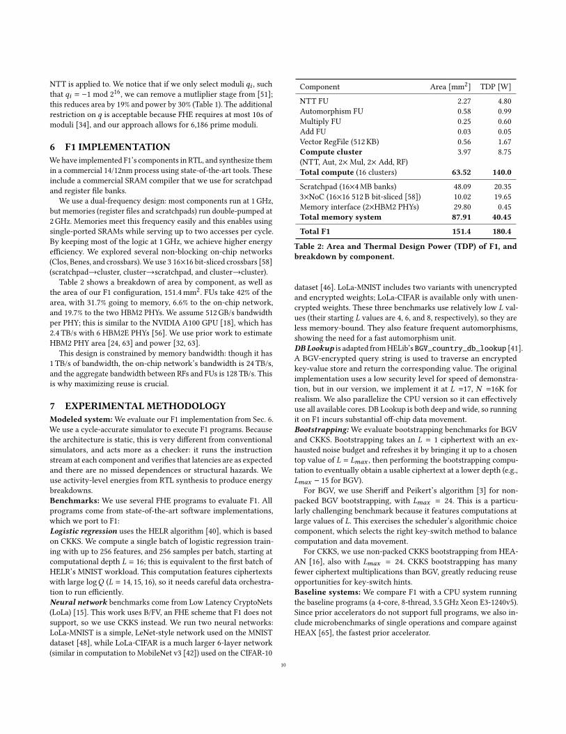
5.2 Four-step NTT unitThere are many ways to implement NTTs in hardware: an NTT islike an FFT [19] but with a butterfly that uses modular multipliers.We implement 𝑁 -element NTTs (from 1K to 16K) as a composi-tion of smaller 𝐸=128-element NTTs, since implementing a full16K-element NTT datapath is prohibitive. The challenge is thatstandard approaches result in memory access patterns that are hardto vectorize.
To that end, we use the four-step variant of the FFT algorithm [6],which adds an extra multiplication to produce a vector-friendlydecomposition. Fig. 8 illustrates our four-step NTT pipeline for 𝐸 =
4; we use the same structure with 𝐸 = 128. The unit is fully pipelinedand consumes 𝐸 elements per cycle. To compute an 𝑁 = 𝐸 ×𝐸 NTT,the unit first computes an 𝐸-point NTT on each 𝐸-element group,multiplies each group with twiddles, transposes the 𝐸 groups, andcomputes another 𝐸-element NTT on each transpose. The sameNTT unit implements the inverse NTT by storing multiplicativefactors (twiddles) required for both forward and inverse NTTs in asmall twiddle SRAM.
Crucially, we are able to support all values of 𝑁 using a singlefour-step NTT pipeline by conditionally bypassing layers in the sec-ond NTT butterfly. We use the same transpose unit implementationas with automorphisms.
Our four-step pipeline supports negacyclic NTTs (NCNs), whichare more efficient than standard non-negacyclic NTTs (that wouldrequire padding, Sec. 2.3). Specifically, we extend prior work [49,62, 67] in order to support both forward and inverse NCNs usingthe same hardware as for the standard NTT. Namely, prior workshows how to either (1) perform a forward NCN via a standarddecimation-in-time (DIT) NTT pipeline, or (2) perform an inverseNCN via a standard decimation-in-frequency (DIF) NTT pipeline.The DIF and DIT NTT variants use different hardware; therefore,this approach requires separate pipelines for forward and inverseNCNs. Prior work [49] has shown that separate pipelines can beavoided by adding a multiplier either before or after the NTT: doingan inverse NCN using a DIT NTT requires a multiplier unit afterthe NTT, while doing a forward NCN using a DIF NTT requires amultiplier unit before the NTT.
We now show that both the forward and inverse NCN can be donein the same standard four-step NTT pipeline, with no additionalhardware. This is because the four-step NTT already has amultiplierand two NTTs in its pipeline. We set the first NTT to be decimation-in-time and the second to be decimation-in-frequency (Fig. 8). Todo a forward NTT, we use the forward NCN implementation viaDIT NTT for the first NTT; we modify the contents of the TwiddleSRAM so that the multiplier does the pre-multiplication necessaryto implement a forward NCN in the second NTT (which is DIF andthus requires the pre-multiplication). Conversely, to do an inverseNTT, we modify the Twiddle SRAM contents to do the post-multi-plication necessary to implement an inverse NCN in the first NTT(which is DIT); and we use the inverse NCN implementation viaDIF NTT for the second NTT.
The NTT unit is large: each of the 128-element NTTs requires𝐸 (log(𝐸) − 1)/2=384 multipliers, and the full unit uses 896 multi-pliers. But its high throughput improves performance over manylow-throughput NTTs (Sec. 8). This is the first implementation of afully-pipelined four-step NTT unit, improving NTT performanceby 1,600× over the state of the art (Sec. 8.1).
5.3 Optimized modular multiplierModular multiplication computes 𝑎 · 𝑏 mod 𝑞. This is the most ex-pensive and frequent operation. Therefore, improvements to themodular multiplier have an almost linear impact on the computa-tional capabilities of an FHE accelerator.
Prior work [51] recognized that a Montgomery multiplier [55]within NTTs can be improved by leveraging the fact that the possi-ble values of modulus𝑞 are restricted by the number of elements the
Multiplier Area [`m2] Power [mW] Delay [ps]Barrett 5, 271 18.40 1,317Montgomery 2, 916 9.29 1,040NTT-friendly 2, 165 5.36 1,000FHE-friendly (ours) 1, 817 4.10 1,000Table 1: Area, power, and delay of modular multipliers.
9
NTT is applied to. We notice that if we only select moduli 𝑞𝑖 , suchthat 𝑞𝑖 = −1 mod 216, we can remove a mutliplier stage from [51];this reduces area by 19% and power by 30% (Table 1). The additionalrestriction on 𝑞 is acceptable because FHE requires at most 10s ofmoduli [34], and our approach allows for 6,186 prime moduli.
6 F1 IMPLEMENTATIONWehave implemented F1’s components in RTL, and synthesize themin a commercial 14/12nm process using state-of-the-art tools. Theseinclude a commercial SRAM compiler that we use for scratchpadand register file banks.
We use a dual-frequency design: most components run at 1 GHz,but memories (register files and scratchpads) run double-pumped at2 GHz. Memories meet this frequency easily and this enables usingsingle-ported SRAMs while serving up to two accesses per cycle.By keeping most of the logic at 1GHz, we achieve higher energyefficiency. We explored several non-blocking on-chip networks(Clos, Benes, and crossbars).We use 3 16×16 bit-sliced crossbars [58](scratchpad→cluster, cluster→scratchpad, and cluster→cluster).
Table 2 shows a breakdown of area by component, as well asthe area of our F1 configuration, 151.4mm2. FUs take 42% of thearea, with 31.7% going to memory, 6.6% to the on-chip network,and 19.7% to the two HBM2 PHYs. We assume 512GB/s bandwidthper PHY; this is similar to the NVIDIA A100 GPU [18], which has2.4 TB/s with 6 HBM2E PHYs [56]. We use prior work to estimateHBM2 PHY area [24, 63] and power [32, 63].
This design is constrained by memory bandwidth: though it has1 TB/s of bandwidth, the on-chip network’s bandwidth is 24 TB/s,and the aggregate bandwidth between RFs and FUs is 128 TB/s. Thisis why maximizing reuse is crucial.
7 EXPERIMENTAL METHODOLOGYModeled system:We evaluate our F1 implementation from Sec. 6.We use a cycle-accurate simulator to execute F1 programs. Becausethe architecture is static, this is very different from conventionalsimulators, and acts more as a checker: it runs the instructionstream at each component and verifies that latencies are as expectedand there are no missed dependences or structural hazards. Weuse activity-level energies from RTL synthesis to produce energybreakdowns.Benchmarks: We use several FHE programs to evaluate F1. Allprograms come from state-of-the-art software implementations,which we port to F1:Logistic regression uses the HELR algorithm [40], which is basedon CKKS. We compute a single batch of logistic regression train-ing with up to 256 features, and 256 samples per batch, starting atcomputational depth 𝐿 = 16; this is equivalent to the first batch ofHELR’s MNIST workload. This computation features ciphertextswith large log𝑄 (𝐿 = 14, 15, 16), so it needs careful data orchestra-tion to run efficiently.Neural network benchmarks come from Low Latency CryptoNets(LoLa) [15]. This work uses B/FV, an FHE scheme that F1 does notsupport, so we use CKKS instead. We run two neural networks:LoLa-MNIST is a simple, LeNet-style network used on the MNISTdataset [48], while LoLa-CIFAR is a much larger 6-layer network(similar in computation to MobileNet v3 [42]) used on the CIFAR-10
Component Area [mm2] TDP [W]NTT FU 2.27 4.80Automorphism FU 0.58 0.99Multiply FU 0.25 0.60Add FU 0.03 0.05Vector RegFile (512 KB) 0.56 1.67Compute cluster 3.97 8.75(NTT, Aut, 2× Mul, 2× Add, RF)Total compute (16 clusters) 63.52 140.0
Scratchpad (16×4MB banks) 48.09 20.353×NoC (16×16 512 B bit-sliced [58]) 10.02 19.65Memory interface (2×HBM2 PHYs) 29.80 0.45Total memory system 87.91 40.45
Total F1 151.4 180.4
Table 2: Area and Thermal Design Power (TDP) of F1, andbreakdown by component.
dataset [46]. LoLa-MNIST includes two variants with unencryptedand encrypted weights; LoLa-CIFAR is available only with unen-crypted weights. These three benchmarks use relatively low 𝐿 val-ues (their starting 𝐿 values are 4, 6, and 8, respectively), so they areless memory-bound. They also feature frequent automorphisms,showing the need for a fast automorphism unit.DBLookup is adapted fromHELib’s BGV_country_db_lookup [41].A BGV-encrypted query string is used to traverse an encryptedkey-value store and return the corresponding value. The originalimplementation uses a low security level for speed of demonstra-tion, but in our version, we implement it at 𝐿 =17, 𝑁 =16K forrealism. We also parallelize the CPU version so it can effectivelyuse all available cores. DB Lookup is both deep and wide, so runningit on F1 incurs substantial off-chip data movement.Bootstrapping: We evaluate bootstrapping benchmarks for BGVand CKKS. Bootstrapping takes an 𝐿 = 1 ciphertext with an ex-hausted noise budget and refreshes it by bringing it up to a chosentop value of 𝐿 = 𝐿𝑚𝑎𝑥 , then performing the bootstrapping compu-tation to eventually obtain a usable ciphertext at a lower depth (e.g.,𝐿𝑚𝑎𝑥 − 15 for BGV).
For BGV, we use Sheriff and Peikert’s algorithm [3] for non-packed BGV bootstrapping, with 𝐿𝑚𝑎𝑥 = 24. This is a particu-larly challenging benchmark because it features computations atlarge values of 𝐿. This exercises the scheduler’s algorithmic choicecomponent, which selects the right key-switch method to balancecomputation and data movement.
For CKKS, we use non-packed CKKS bootstrapping from HEA-AN [16], also with 𝐿𝑚𝑎𝑥 = 24. CKKS bootstrapping has manyfewer ciphertext multiplications than BGV, greatly reducing reuseopportunities for key-switch hints.Baseline systems: We compare F1 with a CPU system runningthe baseline programs (a 4-core, 8-thread, 3.5 GHz Xeon E3-1240v5).Since prior accelerators do not support full programs, we also in-clude microbenchmarks of single operations and compare againstHEAX [65], the fastest prior accelerator.
10
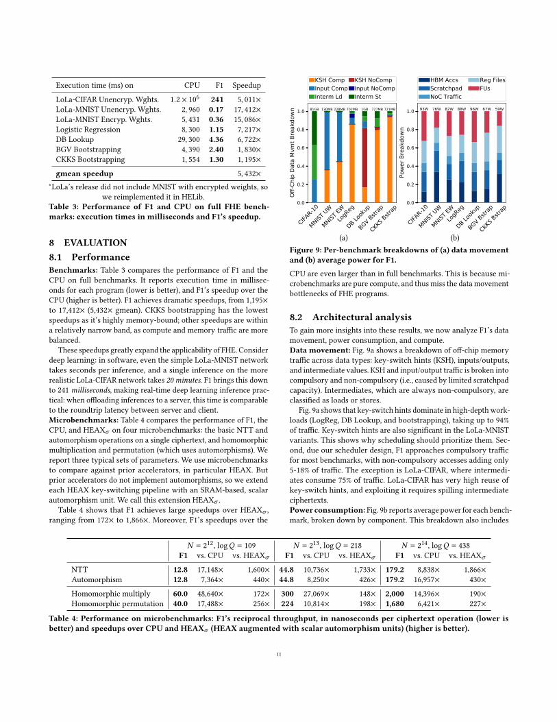
Execution time (ms) on CPU F1 Speedup
LoLa-CIFAR Unencryp. Wghts. 1.2 × 10⁶ 241 5, 011×LoLa-MNIST Unencryp. Wghts. 2, 960 0.17 17, 412×LoLa-MNIST Encryp. Wghts. 5, 431 0.36 15, 086×Logistic Regression 8, 300 1.15 7, 217×DB Lookup 29, 300 4.36 6, 722×BGV Bootstrapping 4, 390 2.40 1, 830×CKKS Bootstrapping 1, 554 1.30 1, 195×gmean speedup 5, 432×
∗LoLa’s release did not include MNIST with encrypted weights, sowe reimplemented it in HELib.
Table 3: Performance of F1 and CPU on full FHE bench-marks: execution times in milliseconds and F1’s speedup.
8 EVALUATION8.1 PerformanceBenchmarks: Table 3 compares the performance of F1 and theCPU on full benchmarks. It reports execution time in millisec-onds for each program (lower is better), and F1’s speedup over theCPU (higher is better). F1 achieves dramatic speedups, from 1,195×to 17,412× (5,432× gmean). CKKS bootstrapping has the lowestspeedups as it’s highly memory-bound; other speedups are withina relatively narrow band, as compute and memory traffic are morebalanced.
These speedups greatly expand the applicability of FHE. Considerdeep learning: in software, even the simple LoLa-MNIST networktakes seconds per inference, and a single inference on the morerealistic LoLa-CIFAR network takes 20 minutes. F1 brings this downto 241 milliseconds, making real-time deep learning inference prac-tical: when offloading inferences to a server, this time is comparableto the roundtrip latency between server and client.Microbenchmarks: Table 4 compares the performance of F1, theCPU, and HEAX𝜎 on four microbenchmarks: the basic NTT andautomorphism operations on a single ciphertext, and homomorphicmultiplication and permutation (which uses automorphisms). Wereport three typical sets of parameters. We use microbenchmarksto compare against prior accelerators, in particular HEAX. Butprior accelerators do not implement automorphisms, so we extendeach HEAX key-switching pipeline with an SRAM-based, scalarautomorphism unit. We call this extension HEAX𝜎 .
Table 4 shows that F1 achieves large speedups over HEAX𝜎 ,ranging from 172× to 1,866×. Moreover, F1’s speedups over the
CIFAR-10
MNIST UW
MNIST EWLog
Reg
DB Looku
p
BGV Bstrap
CKKS B
strap
0.0
0.2
0.4
0.6
0.8
1.0
Off-C
hip
Data
Mvm
t Bre
akdo
wn
81GB 130MB 228MB 702MB 1GB 727MB 721MB
KSH CompInput CompInterm Ld
KSH NoCompInput NoCompInterm St
CIFAR-10
MNIST UW
MNIST EWLog
Reg
DB Looku
p
BGV Bstrap
CKKS B
strap
0.0
0.2
0.4
0.6
0.8
1.0
Powe
r Bre
akdo
wn
93W 76W 82W 88W 96W 67W 59W
HBM AccsScratchpadNoC Traffic
Reg FilesFUs
(a) (b)Figure 9: Per-benchmark breakdowns of (a) data movementand (b) average power for F1.
CPU are even larger than in full benchmarks. This is because mi-crobenchmarks are pure compute, and thus miss the data movementbottlenecks of FHE programs.
8.2 Architectural analysisTo gain more insights into these results, we now analyze F1’s datamovement, power consumption, and compute.Data movement: Fig. 9a shows a breakdown of off-chip memorytraffic across data types: key-switch hints (KSH), inputs/outputs,and intermediate values. KSH and input/output traffic is broken intocompulsory and non-compulsory (i.e., caused by limited scratchpadcapacity). Intermediates, which are always non-compulsory, areclassified as loads or stores.
Fig. 9a shows that key-switch hints dominate in high-depthwork-loads (LogReg, DB Lookup, and bootstrapping), taking up to 94%of traffic. Key-switch hints are also significant in the LoLa-MNISTvariants. This shows why scheduling should prioritize them. Sec-ond, due our scheduler design, F1 approaches compulsory trafficfor most benchmarks, with non-compulsory accesses adding only5-18% of traffic. The exception is LoLa-CIFAR, where intermedi-ates consume 75% of traffic. LoLa-CIFAR has very high reuse ofkey-switch hints, and exploiting it requires spilling intermediateciphertexts.Power consumption: Fig. 9b reports average power for each bench-mark, broken down by component. This breakdown also includes
𝑁 = 212, log𝑄 = 109 𝑁 = 213, log𝑄 = 218 𝑁 = 214, log𝑄 = 438F1 vs. CPU vs. HEAX𝜎 F1 vs. CPU vs. HEAX𝜎 F1 vs. CPU vs. HEAX𝜎
NTT 12.8 17,148× 1,600× 44.8 10,736× 1,733× 179.2 8,838× 1,866×Automorphism 12.8 7,364× 440× 44.8 8,250× 426× 179.2 16,957× 430×Homomorphic multiply 60.0 48,640× 172× 300 27,069× 148× 2,000 14,396× 190×Homomorphic permutation 40.0 17,488× 256× 224 10,814× 198× 1,680 6,421× 227×
Table 4: Performance on microbenchmarks: F1’s reciprocal throughput, in nanoseconds per ciphertext operation (lower isbetter) and speedups over CPU and HEAX𝜎 (HEAX augmented with scalar automorphism units) (higher is better).
11
0 20 40 60 80 100 120 140 160Time ( s)
0
10
20
30
Func
tiona
l Uni
ts A
ctiv
e
NTT UnitsAutomorphism UnitsAddersMultipliersHBM Utilization %
0
20
40
60
80
100
HBM
Util
izatio
n %
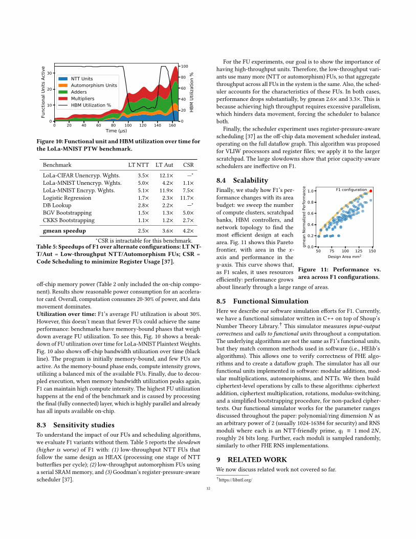
Figure 10: Functional unit andHBMutilization over time forthe LoLa-MNIST PTW benchmark.
Benchmark LT NTT LT Aut CSRLoLa-CIFAR Unencryp. Wghts. 3.5× 12.1× —∗
LoLa-MNIST Unencryp. Wghts. 5.0× 4.2× 1.1×LoLa-MNIST Encryp. Wghts. 5.1× 11.9× 7.5×Logistic Regression 1.7× 2.3× 11.7×DB Lookup 2.8× 2.2× —∗
BGV Bootstrapping 1.5× 1.3× 5.0×CKKS Bootstrapping 1.1× 1.2× 2.7×gmean speedup 2.5× 3.6× 4.2×
∗CSR is intractable for this benchmark.Table 5: Speedups of F1 over alternate configurations: LTNT-T/Aut = Low-throughput NTT/Automorphism FUs; CSR =Code Scheduling to minimize Register Usage [37].
off-chip memory power (Table 2 only included the on-chip compo-nent). Results show reasonable power consumption for an accelera-tor card. Overall, computation consumes 20-30% of power, and datamovement dominates.Utilization over time: F1’s average FU utilization is about 30%.However, this doesn’t mean that fewer FUs could achieve the sameperformance: benchmarks have memory-bound phases that weighdown average FU utilization. To see this, Fig. 10 shows a break-down of FU utilization over time for LoLa-MNIST PlaintextWeights.Fig. 10 also shows off-chip bandwidth utilization over time (blackline). The program is initially memory-bound, and few FUs areactive. As the memory-bound phase ends, compute intensity grows,utilizing a balanced mix of the available FUs. Finally, due to decou-pled execution, when memory bandwidth utilization peaks again,F1 can maintain high compute intensity. The highest FU utilizationhappens at the end of the benchmark and is caused by processingthe final (fully connected) layer, which is highly parallel and alreadyhas all inputs available on-chip.
8.3 Sensitivity studiesTo understand the impact of our FUs and scheduling algorithms,we evaluate F1 variants without them. Table 5 reports the slowdown(higher is worse) of F1 with: (1) low-throughput NTT FUs thatfollow the same design as HEAX (processing one stage of NTTbutterflies per cycle); (2) low-throughput automorphism FUs usinga serial SRAMmemory, and (3) Goodman’s register-pressure-awarescheduler [37].
For the FU experiments, our goal is to show the importance ofhaving high-throughput units. Therefore, the low-throughput vari-ants use many more (NTT or automorphism) FUs, so that aggregatethroughput across all FUs in the system is the same. Also, the sched-uler accounts for the characteristics of these FUs. In both cases,performance drops substantially, by gmean 2.6× and 3.3×. This isbecause achieving high throughput requires excessive parallelism,which hinders data movement, forcing the scheduler to balanceboth.
Finally, the scheduler experiment uses register-pressure-awarescheduling [37] as the off-chip data movement scheduler instead,operating on the full dataflow graph. This algorithm was proposedfor VLIW processors and register files; we apply it to the largerscratchpad. The large slowdowns show that prior capacity-awareschedulers are ineffective on F1.
8.4 Scalability
50 75 100 125 150Design Area mm2
0.0
0.2
0.4
0.6
0.8
1.0
gmea
n No
rmal
ized
Perfo
rman
ce F1 configuration
Figure 11: Performance vs.area across F1 configurations.
Finally, we study how F1’s per-formance changes with its areabudget: we sweep the numberof compute clusters, scratchpadbanks, HBM controllers, andnetwork topology to find themost efficient design at eacharea. Fig. 11 shows this Paretofrontier, with area in the 𝑥-axis and performance in the𝑦-axis. This curve shows that,as F1 scales, it uses resourcesefficiently: performance growsabout linearly through a large range of areas.
8.5 Functional SimulationHere we describe our software simulation efforts for F1. Currently,we have a functional simulator written in C++ on top of Shoup’sNumber Theory Library.† This simulator measures input-outputcorrectness and calls to functional units throughout a computation.The underlying algorithms are not the same as F1’s functional units,but they match common methods used in software (i.e., HElib’salgorithms). This allows one to verify correctness of FHE algo-rithms and to create a dataflow graph. The simulator has all ourfunctional units implemented in software: modular additions, mod-ular multiplications, automorphisms, and NTTs. We then buildciphertext-level operations by calls to these algorithms: ciphertextaddition, ciphertext multiplication, rotations, modulus-switching,and a simplified bootstrapping procedure, for non-packed cipher-texts. Our functional simulator works for the parameter rangesdiscussed throughout the paper: polynomial/ring dimension 𝑁 asan arbitrary power of 2 (usually 1024-16384 for security) and RNSmoduli where each is an NTT-friendly prime, 𝑞𝑖 ≡ 1 mod 2𝑁 ,roughly 24 bits long. Further, each moduli is sampled randomly,similarly to other FHE RNS implementations.
9 RELATEDWORKWe now discuss related work not covered so far.†https://libntl.org/
12
FHE accelerators: Prior work has proposed accelerators for indi-vidual FHE operations, but not full FHE computations [20, 21, 22,27, 52, 53, 65, 66, 71]. These designs target FPGAs and rely on ahost processor; Sec. 2.4 discussed their limitations. Early designsaccelerated small primitives like NTTs, and were dominated byhost-FPGA communication. State-of-the-art accelerators executea full homomorphic multiplication independently: Roy et al. [66]accelerate B/FV multiplication by 13× over a CPU; HEAWS [71]accelerates B/FV multiplication, and uses it to speed a simple bench-mark by 5×; and HEAX [65] accelerates CKKS multiplication andkey-switching by up to 200×. These designs suffer high data move-ment (e.g., HEAX does not reuse key-switch hints) and use fixedpipelines with relatively low-throughput FUs.
We have shown that accelerating FHE programs requires a differ-ent approach: data movement becomes the key constraint, requiringnew techniques to extract reuse across homomorphic operations;and fixed pipelines cannot support the operations of even a singlebenchmark. Instead, F1 achieves flexibility and high performanceby exploiting wide-vector execution with high-throughput FUs.This lets F1 execute not only full applications, but different FHEschemes.Hybrid HE-MPC accelerators: Recent work has also proposedASIC accelerators for some homomorphic encryption primitives inthe context of oblivious neural networks [44, 64]. These approachesare very different from FHE: they combine homomorphic encryp-tion with multi-party computation (MPC), executing a single layerof the network at a time and sending intermediates to the client,which computes the final activations. Gazelle [44] is a low-powerASIC for homomorphic evaluations, and Cheetah [64] introducesalgorithmic optimizations and a large ASIC design that achievesvery large speedups over Gazelle.
These schemes avoid high-depth FHE programs, so server-sidehomomorphic operations are cheaper. But they are limited by client-side computation and client-server communication: Cheetah andGazelle use ciphertexts that are up to ∼ 40× smaller than those usedby F1; however, they require the client to re-encrypt ciphertextsevery time they aremultiplied on the server to prevent noise blowup.CHOCO [72] shows that client-side computation costs for HE-MPCare substantial, and when they are accelerated, network latencyand throughput overheads dominate (several seconds per DNNinference). By contrast, F1 enables offloading the full inferenceusing FHE, avoiding frequent communication. As a result, a directcomparison between these accelerators and F1 is not possible.
F1’s hardware also differs substantially fromCheetah andGazelle.First, Cheetah and Gazelle implement fixed-function pipelines (e.g.,for output-stationary DNN inference in Cheetah), whereas F1 isprogrammable. Second, Cheetah, like HEAX, uses many FUs withrelatively low throughput, whereas F1 uses few high-throughputunits (e.g., 40× faster NTTs). Cheetah’s approach makes sense fortheir small ciphertexts, but as we have seen (Sec. 8.3), it is impracti-cal for FHE.GPU acceleration: Finally, prior work has also used GPUs to ac-celerate different FHE schemes, including GH [74, 75], BGV [73],and B/FV [1]. Though GPUs have plentiful compute and band-width, they lack modular arithmetic, their pure data-parallel ap-proach makes non-element-wise operations like NTTs expensive,and their small on-chip storage adds data movement. As a result,
GPUs achieve only modest performance gains. For instance, Badawiet al. [1] accelerate B/FV multiplication using GPUs, and achievespeedups of around 10× to 100× over single-thread CPU execution(and thus commensurately lower speedups over multicore CPUs,as FHE operations parallelize well).
10 CONCLUSIONFHE has the potential to enable computation offloading with guar-anteed security. But FHE’s high computation overheads currentlylimit its applicability to narrow cases (simple computations whereprivacy is paramount). F1 tackles this challenge, accelerating fullFHE computations by over 3-4 orders of magnitude. This enablesnew use cases for FHE, like secure real-time deep learning inference.
F1 is the first FHE accelerator that is programmable, i.e., capa-ble of executing full FHE programs. In contrast to prior accelera-tors, which build fixed pipelines tailored to specific FHE schemesand parameters, F1 introduces a more effective design approach:it accelerates the primitive computations shared by higher-leveloperations using novel high-throughput functional units, and hard-ware and compiler are co-designed to minimize data movement, thekey bottleneck. This flexibility makes F1 broadly useful: the samehardware can accelerate all operations within a program, arbitraryFHE programs, and even multiple FHE schemes. In short, our keycontribution is to show that, for FHE, we can achieve ASIC-levelperformance without sacrificing programmability.
ACKNOWLEDGMENTSWe thank the anonymous reviewers, Maleen Abeydeera, Hyun Ry-ong Lee, Quan Nguyen, Yifan Yang, Victor Ying, Guowei Zhang, andJoel Emer for feedback on the paper; Tutu Ajayi, Austin Rovinski,and Peter Li for help with the HDL toolchain setup; Shai Halevi, WeiDai, Olli Saarikivi, and Madan Musuvathi for email correspondence.This research was developed with funding from the Defense Ad-vanced Research Projects Agency (DARPA) under contract numberContract No. HR0011-21-C-0035. The views, opinions and/or find-ings expressed are those of the author and should not be interpretedas representing the official views or policies of the Department ofDefense or the U.S. Government. Nikola Samardzic was supportedby the Jae S. and Kyuho Lim Graduate Fellowship at MIT.
REFERENCES[1] A. Q. A. Al Badawi, Y. Polyakov, K. M. M. Aung, B. Veeravalli, and K. Rohloff,
“Implementation and performance evaluation of RNS variants of the BFV homo-morphic encryption scheme,” IEEE Transactions on Emerging Topics in Computing,vol. 9, no. 2, 2021.
[2] M. Albrecht, M. Chase, H. Chen, J. Ding, S. Goldwasser, S. Gorbunov, S. Halevi,J. Hoffstein, K. Laine, K. Lauter, S. Lokam, D. Micciancio, D. Moody, T. Morrison,A. Sahai, and V. Vaikuntanathan, “Homomorphic encryption security standard,”HomomorphicEncryption.org, Tech. Rep., 2018.
[3] J. Alperin-Sheriff and C. Peikert, “Practical bootstrapping in quasilinear time,” inAnnual Cryptology Conference, 2013.
[4] D. Altavilla, “Intel and Microsoft Collaborate on DARPA Program that PioneersA New Frontier Of Ultra-Secure Computing,” https://www.forbes.com/sites/davealtavilla/2021/03/08/intel-and-microsoft-collaborate-on-darpa-program-that-pioneers-a-new-frontier-of-ultra-secure-computing/?sh=60db31567c1aarchived at https://perma.cc/YYE6-5FT4, 2021.
[5] K. Asanovic, “Vector microprocessors,” Ph.D. dissertation, EECS Department,University of California, Berkeley, 1998.
[6] D. H. Bailey, “FFTs in external of hierarchical memory,” in Proceedings of the 1989ACM/IEEE conference on Supercomputing, 1989.
[7] G. Barany, “Register reuse scheduling,” in 9th Workshop on Optimizations for DSPand Embedded Systems (ODES-9), 2011.
13
[8] L. A. Belady, “A study of replacement algorithms for a virtual-storage computer,”IBM Systems journal, vol. 5, no. 2, 1966.
[9] F. Bergamaschi, “IBM Releases Fully Homomorphic Encryption Toolkit for Ma-cOS and iOS,” https://www.ibm.com/blogs/research/2020/06/ibm-releases-fully-homomorphic-encryption-toolkit-for-macos-and-ios-linux-and-android-coming-soon/ archived at https://perma.cc/U5TQ-K49C, 2020.
[10] D. A. Berson, R. Gupta, and M. L. Soffa, “URSA: A Unified ReSource Allocator forRegisters and Functional Units in VLIW Architectures,” in Proceedings of the IFIPWG10.3 Working Conference on Architectures and Compilation Techniques for Fineand Medium Grain Parallelism (PACT’93), 1993.
[11] M. Blatt, A. Gusev, Y. Polyakov, and S. Goldwasser, “Secure large-scale genome-wide association studies using homomorphic encryption,” Proceedings of theNational Academy of Sciences, vol. 117, no. 21, 2020.
[12] G. E. Blelloch, P. B. Gibbons, and Y. Matias, “Provably efficient scheduling forlanguages with fine-grained parallelism,” Journal of the ACM (JACM), vol. 46,no. 2, 1999.
[13] Z. Brakerski, “Fully homomorphic encryption without modulus switching fromclassical GapSVP,” in Annual Cryptology Conference, 2012.
[14] Z. Brakerski, C. Gentry, and V. Vaikuntanathan, “(leveled) fully homomorphicencryption without bootstrapping,” ACM Transactions on Computation Theory(TOCT), vol. 6, no. 3, 2014.
[15] A. Brutzkus, R. Gilad-Bachrach, and O. Elisha, “Low latency privacy preservinginference,” in Proceedings of the International Conference on Machine Learning(ICML), 2019.
[16] J. H. Cheon, K. Han, A. Kim, M. Kim, and Y. Song, “Bootstrapping for approximatehomomorphic encryption,” in Annual International Conference on the Theory andApplications of Cryptographic Techniques, 2018.
[17] J. H. Cheon, A. Kim, M. Kim, and Y. Song, “Homomorphic encryption for arith-metic of approximate numbers,” in International Conference on the Theory andApplication of Cryptology and Information Security, 2017.
[18] J. Choquette, W. Gandhi, O. Giroux, N. Stam, and R. Krashinsky, “Nvidia a100tensor core gpu: Performance and innovation,” IEEE Micro, vol. 41, no. 2, 2021.
[19] J. W. Cooley and J. W. Tukey, “An algorithm for the machine calculation ofcomplex Fourier series,” Mathematics of computation, vol. 19, no. 90, 1965.
[20] D. B. Cousins, K. Rohloff, and D. Sumorok, “Designing an FPGA-acceleratedhomomorphic encryption co-processor,” IEEE Transactions on Emerging Topics inComputing, vol. 5, no. 2, 2017.
[21] D. B. Cousins, J. Golusky, K. Rohloff, and D. Sumorok, “An FPGA co-processor im-plementation of homomorphic encryption,” in Proceedings of the IEEE Conferenceon High Performance Extreme Computing (HPEC), 2014.
[22] D. B. Cousins, K. Rohloff, C. Peikert, and R. Schantz, “An update on SIPHER(Scalable Implementation of Primitives for Homomorphic EncRyption) - FPGAimplementation using Simulink,” in Proceedings of the IEEE Conference on HighPerformance Extreme Computing (HPEC), 2012.
[23] DARPA, “DARPA Selects Researchers to Accelerate Use of Fully HomomorphicEncryption,” https://www.darpa.mil/news-events/2021-03-08 archived at https://perma.cc/6GHW-2MSN, 2021.
[24] S. Dasgupta, T. Singh, A. Jain, S. Naffziger, D. John, C. Bisht, and P. Jayaraman,“Radeon RX 5700 Series: The AMD 7nm Energy-Efficient High-PerformanceGPUs,” in Proceedings of the IEEE International Solid-State Circuits Conference(ISSCC), 2020.
[25] R. Dathathri, B. Kostova, O. Saarikivi, W. Dai, K. Laine, and M. Musuvathi, “EVA:An encrypted vector arithmetic language and compiler for efficient homomorphiccomputation,” in Proceedings of the 41st ACM SIGPLANConference on ProgrammingLanguage Design and Implementation, 2020.
[26] R. Dathathri, O. Saarikivi, H. Chen, K. Laine, K. Lauter, S. Maleki, M. Musuvathi,and T. Mytkowicz, “CHET: an optimizing compiler for fully-homomorphic neural-network inferencing,” in Proceedings of the 40th ACM SIGPLAN Conference onProgramming Language Design and Implementation, 2019.
[27] Y. Doröz, E. Öztürk, and B. Sunar, “Accelerating fully homomorphic encryptionin hardware,” IEEE Trans. Computers, vol. 64, no. 6, 2015.
[28] J. Fan and F. Vercauteren, “Somewhat practical fully homomorphic encryption.”IACR Cryptol. ePrint Arch., 2012.
[29] A. Feldmann, N. Samardzic, A. Krastev, S. Devadas, R. Dreslinski, C. Peikert, andD. Sanchez, “F1: A fast and programmable accelerator for fully homomorphicencryption,” in Proceedings of the 54th annual ACM/IEEE International Symposiumon Microarchitecture, 2021.
[30] J. A. Fisher, “Very long instruction word architectures and the ELI-512,” in Pro-ceedings of the 10th annual international symposium on Computer architecture,1983.
[31] H. L. Garner, “The residue number system,” in Papers presented at the the March3-5, 1959, Western Joint Computer Conference, 1959.
[32] W. Ge, M. Zhao, C. Wu, and J. He, “The design and implementation of ddrphy static low-power optimization strategies,” in Communication Systems andInformation Technology, 2011.
[33] C. Gentry et al., A fully homomorphic encryption scheme. Stanford University,2009, vol. 20, no. 9.
[34] C. Gentry, S. Halevi, and N. P. Smart, “Homomorphic evaluation of the AEScircuit,” in Annual Cryptology Conference, 2012.
[35] C. Gentry, A. Sahai, and B. Waters, “Homomorphic encryption from learning witherrors: Conceptually-simpler, asymptotically-faster, attribute-based,” in AnnualCryptology Conference, 2013.
[36] R. Gilad-Bachrach, N. Dowlin, K. Laine, K. Lauter, M. Naehrig, and J. Wernsing,“Cryptonets: Applying neural networks to encrypted data with high throughputand accuracy,” in Proceedings of the International Conference on Machine Learning(ICML), 2016.
[37] J. R. Goodman and W.-C. Hsu, “Code scheduling and register allocation in largebasic blocks,” in Proceedings of the 2nd International Conference on Supercomputing(ICS), 1988.
[38] S. Halevi and V. Shoup, “Algorithms in HElib,” in Annual Cryptology Conference,2014.
[39] K. Han, S. Hong, J. H. Cheon, and D. Park, “Efficient logistic regression on largeencrypted data,” IACR Cryptol. ePrint Arch., 2018.
[40] K. Han, S. Hong, J. H. Cheon, and D. Park, “Logistic regression on homomorphicencrypted data at scale,” in Proceedings of the AAAI Conference on ArtificialIntelligence, vol. 33, no. 01, 2019.
[41] HElib, “HElib country lookup example,” https://github.com/homenc/HElib/tree/master/examples/BGV_country_db_lookup archived at https://perma.cc/U2MW-QLRJ, 2019.
[42] A. Howard, M. Sandler, G. Chu, L.-C. Chen, B. Chen, M. Tan, W. Wang, Y. Zhu,R. Pang, V. Vasudevan et al., “Searching for mobilenet v3,” in Proceedings of theIEEE/CVF International Conference on Computer Vision, 2019.
[43] IBM, “Cost of a Data Breach Report,” Tech. Rep., 2020.[44] C. Juvekar, V. Vaikuntanathan, and A. Chandrakasan, “GAZELLE: A low latency
framework for secure neural network inference,” in 27th USENIX Security Sympo-sium (USENIX Security 18), 2018.
[45] M. Kim, Y. Song, S. Wang, Y. Xia, and X. Jiang, “Secure logistic regression basedon homomorphic encryption: Design and evaluation,” JMIR medical informatics,vol. 6, no. 2, 2018.
[46] A. Krizhevsky, “Learning multiple layers of features from tiny images,” Universityof Toronto, Tech. Rep., 2009.
[47] M. S. Lam, “Software pipelining,” in Proceedings of the ACM SIGPLAN Conferenceon Programming Language Design and Implementation (PLDI), 1988.
[48] Y. Lecun, L. Bottou, Y. Bengio, and P. Haffner, “Gradient-based learning appliedto document recognition,” Proceedings of the IEEE, vol. 86, no. 11, 1998.
[49] V. Lyubashevsky, C. Peikert, and O. Regev, “On ideal lattices and learning with er-rors over rings,” in Annual International Conference on the Theory and Applicationsof Cryptographic Techniques, 2010.
[50] L. Marchal, B. Simon, and F. Vivien, “Limiting the memory footprint when dy-namically scheduling dags on shared-memory platforms,” Journal of Parallel andDistributed Computing, vol. 128, 2019.
[51] A. C. Mert, E. Öztürk, and E. Savaş, “Design and implementation of a fast andscalable NTT-based polynomial multiplier architecture,” in 2019 22nd EuromicroConference on Digital System Design (DSD), 2019.
[52] A. C. Mert, E. Öztürk, and E. Savaş, “Design and Implementation of Encryp-tion/Decryption Architectures for BFV Homomorphic Encryption Scheme,” IEEETransactions on Very Large Scale Integration (VLSI) Systems, 2019.
[53] V. Migliore, C. Seguin, M. M. Real, V. Lapotre, A. Tisserand, C. Fontaine, G. Gog-niat, and R. Tessier, “A high-speed accelerator for homomorphic encryption usingthe karatsuba algorithm,” ACM Trans. Embedded Comput. Syst., vol. 16, no. 5s,2017.
[54] R. T. Moenck, “Practical fast polynomial multiplication,” in Proceedings of thethird ACM symposium on Symbolic and algebraic computation, 1976.
[55] P. L. Montgomery, “Modular multiplication without trial division,” Mathematicsof computation, vol. 44, no. 170, 1985.
[56] NVIDIA, “NVIDIA DGX station A100 system architecture,” https://images.nvidia.com/aem-dam/Solutions/Data-Center/nvidia-dgx-station-a100-system-architecture-white-paper.pdf archived at https://perma.cc/3CSS-PXU7, 2021.
[57] E. Ozer, S. Banerjia, and T. M. Conte, “Unified assign and schedule: A new ap-proach to scheduling for clustered register file microarchitectures,” in Proceedingsof the 31st annual ACM/IEEE International Symposium on Microarchitecture, 1998.
[58] G. Passas, M. Katevenis, and D. Pnevmatikatos, “Crossbar NoCs are scalablebeyond 100 nodes,” IEEE Transactions on Computer-Aided Design of IntegratedCircuits and Systems, vol. 31, no. 4, 2012.
[59] C. Peikert, “A decade of lattice cryptography,” Foundations and Trends in Theoret-ical Computer Science, vol. 10, no. 4, 2016.
[60] M. Pellauer, Y. S. Shao, J. Clemons, N. Crago, K. Hegde, R. Venkatesan, S. W. Keck-ler, C.W. Fletcher, and J. Emer, “Buffets: An efficient and composable storage idiomfor explicit decoupled data orchestration,” in Proceedings of the Twenty-FourthInternational Conference on Architectural Support for Programming Languages andOperating Systems, 2019.
[61] Y. Polyakov, K. Rohloff, and G. W. Ryan, “Palisade lattice cryptography libraryuser manual,” Cybersecurity Research Center, New Jersey Institute ofTechnology(NJIT), Tech. Rep, vol. 15, 2017.
14
[62] T. Pöppelmann, T. Oder, and T. Güneysu, “High-performance ideal lattice-basedcryptography on 8-bit atxmega microcontrollers,” in International Conference onCryptology and Information Security in Latin America, 2015.
[63] Rambus Inc., “White paper: HBM2E and GDDR6: Memory solutions for AI,” 2020.[64] B. Reagen, W. Choi, Y. Ko, V. Lee, G.-Y. Wei, H.-H. S. Lee, and D. Brooks, “Cheetah:
Optimizations and methods for privacy preserving inference via homomorphicencryption,” in Proceedings of the 27th IEEE international symposium on HighPerformance Computer Architecture (HPCA-27), 2021.
[65] M. S. Riazi, K. Laine, B. Pelton, andW. Dai, “HEAX: An architecture for computingon encrypted data,” in Proceedings of the 25th international conference on Architec-tural Support for Programming Languages and Operating Systems (ASPLOS-XXV),2020.
[66] S. S. Roy, F. Turan, K. Järvinen, F. Vercauteren, and I. Verbauwhede, “Fpga-based high-performance parallel architecture for homomorphic computing onencrypted data,” in Proceedings of the 25th IEEE international symposium on HighPerformance Computer Architecture (HPCA-25), 2019.
[67] S. S. Roy, F. Vercauteren, N. Mentens, D. D. Chen, and I. Verbauwhede, “Compactring-LWE cryptoprocessor,” in International workshop on cryptographic hardwareand embedded systems, 2014.
[68] Q. Shang, Y. Fan,W. Shen, S. Shen, and X. Zeng, “Single-port sram-based transposememory with diagonal data mapping for large size 2-d dct/idct,” IEEE Transactionson Very Large Scale Integration (VLSI) Systems, vol. 22, no. 11, 2014.
[69] Z. M. Smith, E. Lostri, and J. A. Lewis, “The Hidden Costs of Cybercrime,” Centerfor Strategic and International Studies, Tech. Rep., 2020.
[70] S.-A.-A. Touati, “Register saturation in instruction level parallelism,” InternationalJournal of Parallel Programming, vol. 33, 2005.
[71] F. Turan, S. Roy, and I. Verbauwhede, “HEAWS: An Accelerator for HomomorphicEncryption on the Amazon AWS FPGA,” IEEE Transactions on Computers, 2020.
[72] M. van der Hagen and B. Lucia, “Practical encrypted computing for iot clients,”arXiv preprint arXiv:2103.06743, 2021.
[73] W. Wang, Z. Chen, and X. Huang, “Accelerating leveled fully homomorphicencryption using gpu,” in Proceedings of the IEEE International Symposium onCircuits and Systems (ISCAS), 2014.
[74] W. Wang, Y. Hu, L. Chen, X. Huang, and B. Sunar, “Accelerating fully homo-morphic encryption using gpu,” in Proceedings fo the IEEE conference on HighPerformance Extreme Computing (HPEC), 2012.
[75] W. Wang, Y. Hu, L. Chen, X. Huang, and B. Sunar, “Exploring the feasibility offully homomorphic encryption,” IEEE Transactions on Computers, vol. 64, no. 3,2013.
[76] Y. Wang, Z. Ma, and F. Yu, “Pipelined algorithm and modular architecture formatrix transposition,” IEEE Transactions on Circuits and Systems II: Express Briefs,vol. 66, no. 4, 2018.
[77] W. Xu and R. Tessier, “Tetris: a new register pressure control technique for VLIWprocessors,” ACM SIGPLAN Notices, vol. 42, no. 7, 2007.
[78] B. Zhang, Z. Ma, and F. Yu, “A novel pipelined algorithm andmodular architecturefor non-square matrix transposition,” IEEE Transactions on Circuits and SystemsII: Express Briefs, 2020.
15


![iPIM: Programmable In-Memory Image Processing Accelerator ... · photography, image processing is becoming an increas-ingly important domain on workstations [48] and the data-](https://img.pdfslide.us/doc/110x75/5f4856a63777fc69b771802d/ipim-programmable-in-memory-image-processing-accelerator-photography-image.jpg)