Embed Size (px)
Citation preview
EN
Installation Guide
Network Interface Module
DX4020-EXP
DX4020-EXP | Installation Guide | 1. Introduction EN | 2
Bosch Security Sys | 8/04 | F01U002192B
Trademarks Microsoft®-and Windows® are either registered trademarks or trademarks of Microsoft Corporation in the United States and/or other countries.
Lantronix is a registered trademark of Lantronix Corporation, registered in the U.S. and other countries.
XPort with its patent-pending technology is a trademark of Lantronix, Inc.
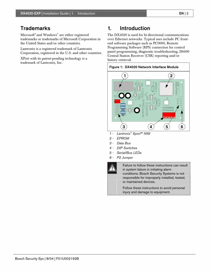
1. Introduction The DX4020 is used for bi-directional communications over Ethernet networks. Typical uses include PC front-end software packages such as PC9000, Remote Programming Software (RPS) connection for control panel programming, diagnostic troubleshooting, D6600 Central Station Receiver (CSR) reporting and/or history retrieval.
Figure 1: DX4020 Network Interface Module
1
3
2
4 5 6 1 - Lantronix® Xport™ NIM 2 - EPROM 3 - Data Bus 4 - DIP Switches 5 - Serial/Bus LEDs 6 - P2 Jumper
Failure to follow these instructions can result in system failure in initiating alarm conditions. Bosch Security Systems is not responsible for improperly installed, tested, or maintained devices.
Follow these instructions to avoid personal injury and damage to equipment.
DX4020-EXP | Installation Guide | 2. Overview EN | 3
Bosch Security Sys | 8/04 | F01U002192B
2. Overview 2.1 Specifications
Table 1: DX4020 Specifications
Dimensions 7.6 cm x 12.7 cm (3 in. x 5 in.) Current Draw 84 mA max, 80 mA nominal 10 Base-T
110 mA max, 100 mA nominal 100 Base-T Operation Voltage
12 VDC Nominal
Control Panel
Option/Data Bus Terminal Strip
Connectors
LAN/WAN RJ-45 Modular Jack (Ethernet)
Category 3 or better unshielded twisted pair
Ethernet Cable
Max Length 100 m (328 ft)
Interface IEEE 802.3 Control Panel Firmware D9412G, D7412G, D7212G, D9412, D9112, D7412, D7212
6.3 or later
DS7240V2, DS7220V2 2.xx or later
Compatibility
DS7400xi 4.10 or later Default IP Address
0.0.0.0 (DHCP mode)
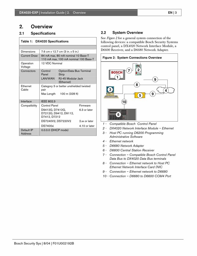
2.2 System Overview See Figure 2 for a general system connection of the following devices: a compatible Bosch Security Systems control panel, a DX4020 Network Interface Module, a D6600 Receiver, and a D6680 Network Adapter.
Figure 2: System Connections Overview
7
3 4
6
1
2
5
7
89
9
10
1 - Compatible Bosch Control Panel 2 - DX4020 Network Interface Module – Ethernet 3 - Host PC running D6200 Programming
Administrative Software 4 - Ethernet network 5 - D6680 Network Adapter 6 - D6600 Central Station Receiver 7 - Connection – Compatible Bosch Control Panel
Data Bus to DX4020 Data Bus terminals 8 - Connection – Ethernet network to Host PC
Ethernet Network Interface Card (NIC 9 - Connection – Ethernet network to D6680 10 - Connection – D6680 to D6600 COM4 Port
DX4020-EXP | Installation Guide | 3. Installation EN | 4
Bosch Security Sys | 8/04 | F01U002192B
3. Installation
Inform the operator and the local authority before installing the DX4020 in an existing system.
Disconnect all power to the control panel before installing the DX4020.
3.1 Mounting the DX4020 The DX4020 can be mounted inside the compatible control panel’s enclosure using any of the standard three-point mounting patterns.
See the control panel’s documentation for complete mounting instructions.
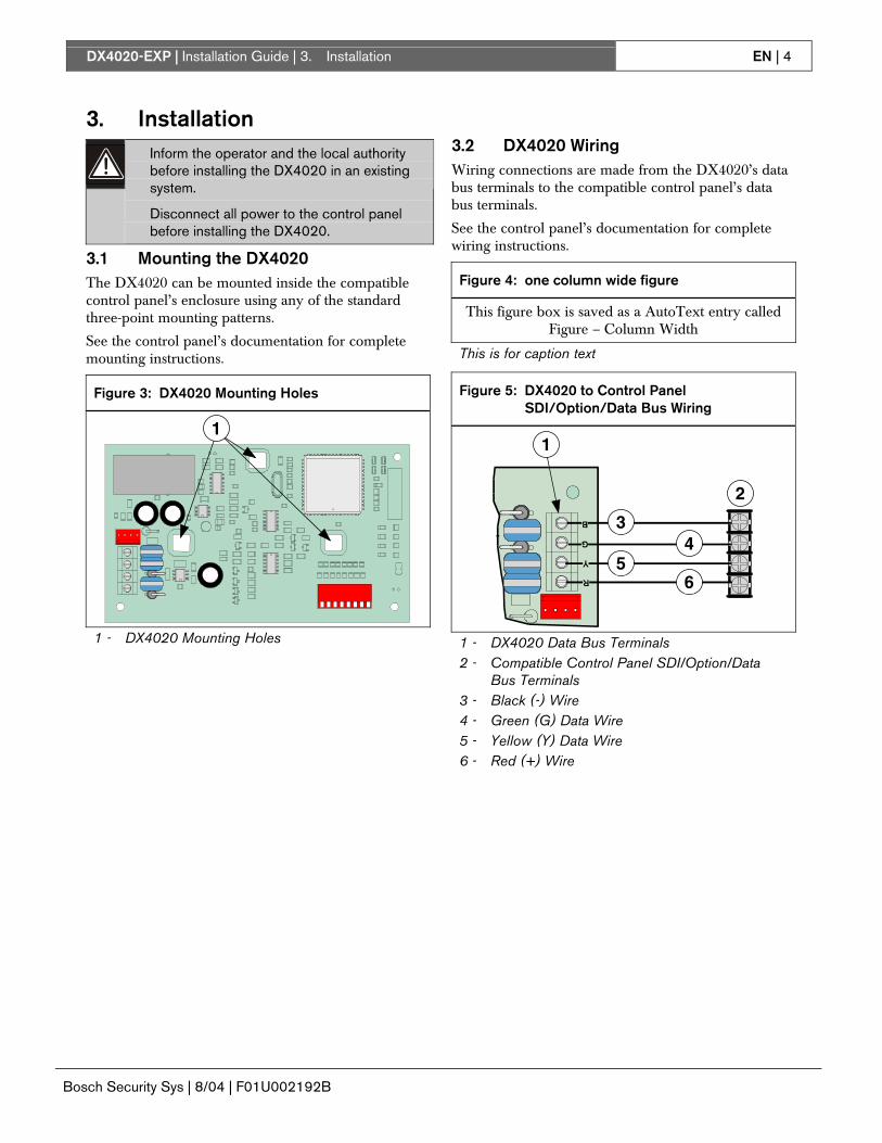
Figure 3: DX4020 Mounting Holes
1
1 - DX4020 Mounting Holes
3.2 DX4020 Wiring Wiring connections are made from the DX4020’s data bus terminals to the compatible control panel’s data bus terminals.
See the control panel’s documentation for complete wiring instructions.
Figure 4: one column wide figure
This figure box is saved as a AutoText entry called Figure – Column Width
This is for caption text
Figure 5: DX4020 to Control Panel SDI/Option/Data Bus Wiring
2
34
56
1
1 - DX4020 Data Bus Terminals 2 - Compatible Control Panel SDI/Option/Data
Bus Terminals 3 - Black (-) Wire 4 - Green (G) Data Wire 5 - Yellow (Y) Data Wire 6 - Red (+) Wire
DX4020-EXP | Installation Guide | 4. DX4020 DIP Switch Settings EN | 5
Bosch Security Sys | 8/04 | F01U002192B
4. DX4020 DIP Switch Settings
Use the following DIP Switch settings for network communication when using the DX4020.
4.1 DIP Switch Address Settings for the D9412G/D9412, D7412G/D7412, D7212G, D9112, D7212 Control Panels
The D9412G/D9412, D7412G/D7412, D7212G, D9112, D7212 control panels require firmware revision 6.3 or later for network communication.
Use SDI Bus Address 80 when using the DX4020 in conjunction with PC9000.
Use SDI Bus Address 88 when using the DX4020 in conjunction with RPS, or for network communication.
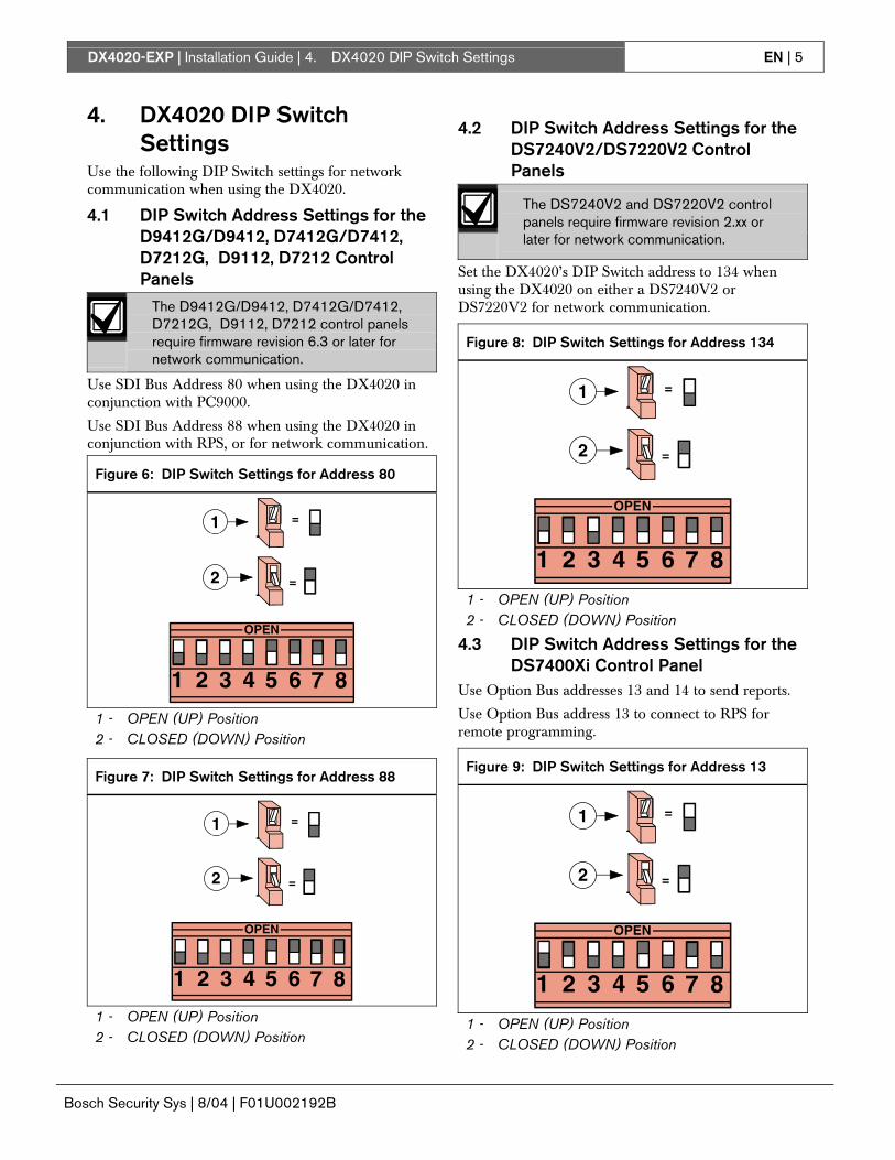
Figure 6: DIP Switch Settings for Address 80
OPEN
1 2 3 4 5 6 7 8
1
2
=
=
1 - OPEN (UP) Position 2 - CLOSED (DOWN) Position
Figure 7: DIP Switch Settings for Address 88
OPEN
1 2 3 4 5 6 7 8
1
2
=
=
1 - OPEN (UP) Position 2 - CLOSED (DOWN) Position
4.2 DIP Switch Address Settings for the DS7240V2/DS7220V2 Control Panels
The DS7240V2 and DS7220V2 control panels require firmware revision 2.xx or later for network communication.
Set the DX4020’s DIP Switch address to 134 when using the DX4020 on either a DS7240V2 or DS7220V2 for network communication.
Figure 8: DIP Switch Settings for Address 134
OPEN
1 2 3 4 5 6 7 8
=
=
1
2
1 - OPEN (UP) Position 2 - CLOSED (DOWN) Position
4.3 DIP Switch Address Settings for the DS7400Xi Control Panel
Use Option Bus addresses 13 and 14 to send reports.
Use Option Bus address 13 to connect to RPS for remote programming.
Figure 9: DIP Switch Settings for Address 13
OPEN
1 2 3 4 5 6 7 8
1
2
=
=
1 - OPEN (UP) Position 2 - CLOSED (DOWN) Position
DX4020-EXP | Installation Guide | EN | 6
Bosch Security Sys | 8/04 | F01U002192B
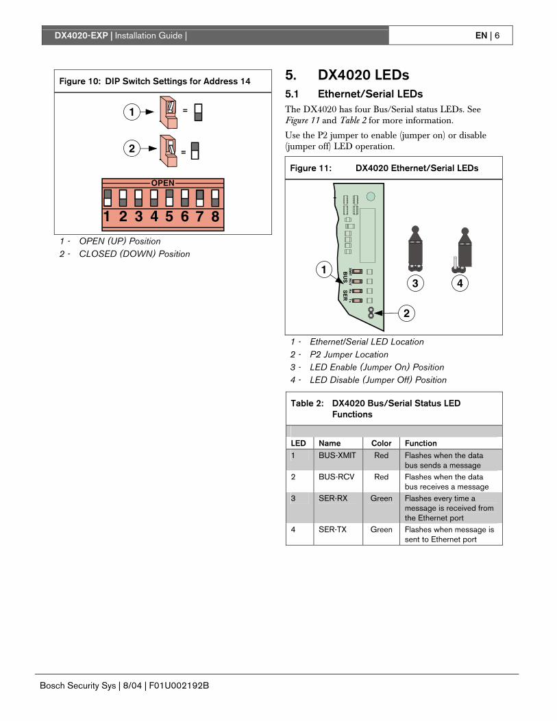
Figure 10: DIP Switch Settings for Address 14
OPEN
1 2 3 4 5 6 7 8
1
2
=
=
1 - OPEN (UP) Position 2 - CLOSED (DOWN) Position
5. DX4020 LEDs 5.1 Ethernet/Serial LEDs The DX4020 has four Bus/Serial status LEDs. See Figure 11 and Table 2 for more information.
Use the P2 jumper to enable (jumper on) or disable (jumper off) LED operation.
Figure 11: DX4020 Ethernet/Serial LEDs
13 4
2
1 - Ethernet/Serial LED Location 2 - P2 Jumper Location 3 - LED Enable (Jumper On) Position 4 - LED Disable (Jumper Off) Position
Table 2: DX4020 Bus/Serial Status LED Functions
LED Name Color Function 1 BUS-XMIT Red Flashes when the data
bus sends a message 2 BUS-RCV Red Flashes when the data
bus receives a message 3 SER-RX Green Flashes every time a
message is received from the Ethernet port
4 SER-TX Green Flashes when message is sent to Ethernet port
DX4020-EXP | Installation Guide | 6. IP Programming EN | 7
Bosch Security Sys | 8/04 | F01U002192B
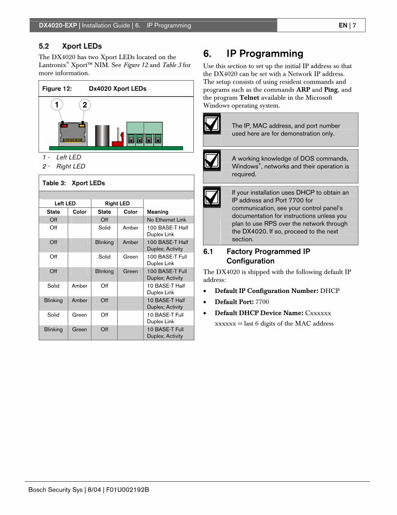
5.2 Xport LEDs The DX4020 has two Xport LEDs located on the Lantronix® Xport™ NIM. See Figure 12 and Table 3 for more information.
Figure 12: Dx4020 Xport LEDs
1 2
1 - Left LED 2 - Right LED
Table 3: Xport LEDs
Left LED Right LED
State Color State Color Meaning Off Off No Ethernet Link Off Solid Amber 100 BASE-T Half
Duplex Link Off Blinking Amber 100 BASE-T Half
Duplex; Activity Off Solid Green 100 BASE-T Full
Duplex Link Off Blinking Green 100 BASE-T Full
Duplex; Activity Solid Amber Off 10 BASE-T Half
Duplex Link Blinking Amber Off 10 BASE-T Half
Duplex; Activity Solid Green Off 10 BASE-T Full
Duplex Link Blinking Green Off 10 BASE-T Full
Duplex; Activity
6. IP Programming Use this section to set up the initial IP address so that the DX4020 can be set with a Network IP address. The setup consists of using resident commands and programs such as the commands ARP and Ping, and the program Telnet available in the Microsoft Windows operating system.
The IP, MAC address, and port number used here are for demonstration only.
A working knowledge of DOS commands, Windows®, networks and their operation is required.
If your installation uses DHCP to obtain an IP address and Port 7700 for communication, see your control panel’s documentation for instructions unless you plan to use RPS over the network through the DX4020. If so, proceed to the next section.
6.1 Factory Programmed IP Configuration
The DX4020 is shipped with the following default IP address:
• Default IP Configuration Number: DHCP
• Default Port: 7700
• Default DHCP Device Name: Cxxxxxx
xxxxxx = last 6 digits of the MAC address
DX4020-EXP | Installation Guide | 6. IP Programming EN | 8
Bosch Security Sys | 8/04 | F01U002192B
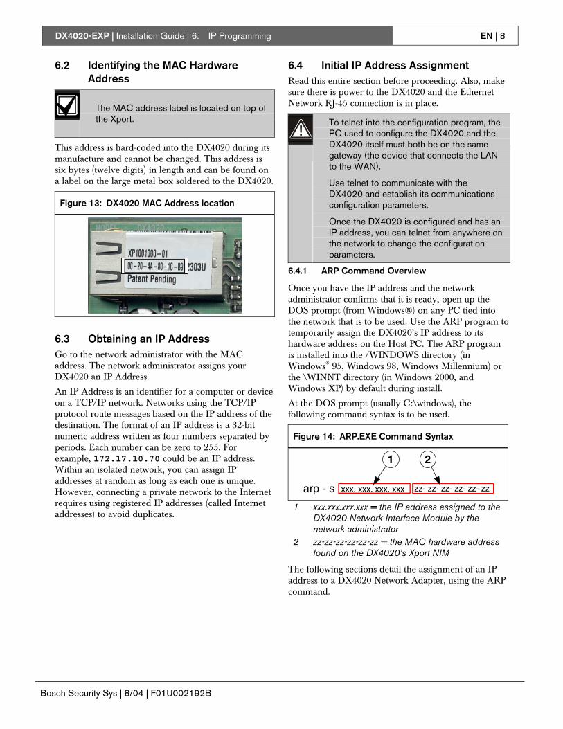
6.2 Identifying the MAC Hardware Address
The MAC address label is located on top of the Xport.
This address is hard-coded into the DX4020 during its manufacture and cannot be changed. This address is six bytes (twelve digits) in length and can be found on a label on the large metal box soldered to the DX4020.
Figure 13: DX4020 MAC Address location
6.3 Obtaining an IP Address Go to the network administrator with the MAC address. The network administrator assigns your DX4020 an IP Address.
An IP Address is an identifier for a computer or device on a TCP/IP network. Networks using the TCP/IP protocol route messages based on the IP address of the destination. The format of an IP address is a 32-bit numeric address written as four numbers separated by periods. Each number can be zero to 255. For example, 172.17.10.70 could be an IP address. Within an isolated network, you can assign IP addresses at random as long as each one is unique. However, connecting a private network to the Internet requires using registered IP addresses (called Internet addresses) to avoid duplicates.
6.4 Initial IP Address Assignment Read this entire section before proceeding. Also, make sure there is power to the DX4020 and the Ethernet Network RJ-45 connection is in place.
To telnet into the configuration program, the PC used to configure the DX4020 and the DX4020 itself must both be on the same gateway (the device that connects the LAN to the WAN).
Use telnet to communicate with the DX4020 and establish its communications configuration parameters.
Once the DX4020 is configured and has an IP address, you can telnet from anywhere on the network to change the configuration parameters.
6.4.1 ARP Command Overview
Once you have the IP address and the network administrator confirms that it is ready, open up the DOS prompt (from Windows®) on any PC tied into the network that is to be used. Use the ARP program to temporarily assign the DX4020’s IP address to its hardware address on the Host PC. The ARP program is installed into the /WINDOWS directory (in Windows® 95, Windows 98, Windows Millennium) or the \WINNT directory (in Windows 2000, and Windows XP) by default during install.
At the DOS prompt (usually C:\windows), the following command syntax is to be used.
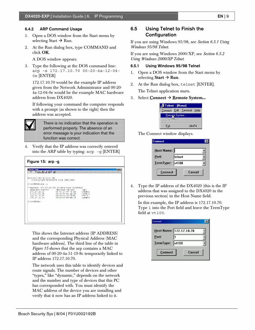
Figure 14: ARP.EXE Command Syntax
1 2
arp - s xxx. xxx. xxx. xxx zz- zz- zz- zz- zz- zz
1 xxx.xxx.xxx.xxx = the IP address assigned to the DX4020 Network Interface Module by the network administrator
2 zz-zz-zz-zz-zz-zz = the MAC hardware address found on the DX4020’s Xport NIM
The following sections detail the assignment of an IP address to a DX4020 Network Adapter, using the ARP command.
DX4020-EXP | Installation Guide | 6. IP Programming EN | 9
Bosch Security Sys | 8/04 | F01U002192B
6.4.2 ARP Command Usage
1. Open a DOS window from the Start menu by selecting Start � Run.
2. At the Run dialog box, type COMMAND and click OK.
A DOS window appears.
3. Type the following at the DOS command line: arp –s 172.17.10.70 00-20-4a-12-04-0e [ENTER]
172.17.10.70 would be the example IP address given from the Network Administrator and 00-20-4a-12-04-0e would be the example MAC hardware address from DX4020.
If following your command the computer responds with a prompt (as shown to the right) then the address was accepted.
There is no indication that the operation is performed properly. The absence of an error message is your indication that the function was correct.
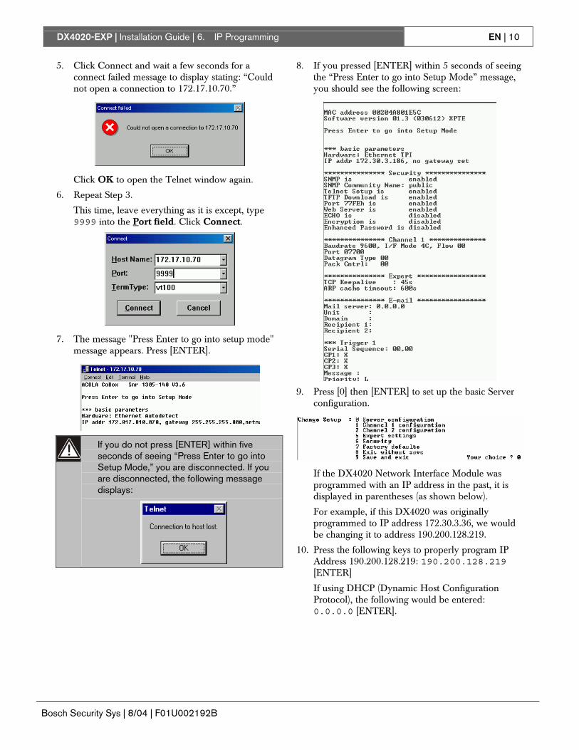
4. Verify that the IP address was correctly entered into the ARP table by typing: arp -g [ENTER]
Figure 15: arp -g
This shows the Internet address (IP ADDRESS) and the corresponding Physical Address (MAC hardware address). The third line of the table in Figure 15 shows that the arp contains a MAC address of 00-20-4a-51-19-8c temporarily linked to IP address 172.17.10.70.
The network uses this table to identify devices and route signals. The number of devices and other “types,” like “dynamic,” depends on the network and the number and type of devices that this PC has corresponded with. You must identify the MAC address of the device you are installing and verify that it now has an IP address linked to it.
6.5 Using Telnet to Finish the Configuration
If you are using Windows 95/98, see Section 6.5.1 Using Windows 95/98 Telnet.
If you are using Windows 2000/XP, see Section 6.5.2 Using Windows 2000/XP Telnet.
6.5.1 Using Windows 95/98 Telnet
1. Open a DOS window from the Start menu by selecting Start � Run.
2. At the Run dialog box, telnet [ENTER].
The Telnet application starts.
3. Select Connect � Remote System...
The Connect window displays.
4. Type the IP address of the DX4020 (this is the IP address that was assigned to the DX4020 in the previous section) in the Host Name field.
In this example, the IP address is 172.17.10.70. Type 1 into the Port field and leave the TermType field at vt100.
DX4020-EXP | Installation Guide | 6. IP Programming EN | 10
Bosch Security Sys | 8/04 | F01U002192B
5. Click Connect and wait a few seconds for a connect failed message to display stating: “Could not open a connection to 172.17.10.70.”
Click OK to open the Telnet window again.
6. Repeat Step 3.
This time, leave everything as it is except, type 9999 into the Port field. Click Connect.
7. The message "Press Enter to go into setup mode" message appears. Press [ENTER].
If you do not press [ENTER] within five seconds of seeing “Press Enter to go into Setup Mode,” you are disconnected. If you are disconnected, the following message displays:
8. If you pressed [ENTER] within 5 seconds of seeing the “Press Enter to go into Setup Mode” message, you should see the following screen:
9. Press [0] then [ENTER] to set up the basic Server
configuration.
If the DX4020 Network Interface Module was programmed with an IP address in the past, it is displayed in parentheses (as shown below).
For example, if this DX4020 was originally programmed to IP address 172.30.3.36, we would be changing it to address 190.200.128.219.
10. Press the following keys to properly program IP Address 190.200.128.219: 190.200.128.219 [ENTER]
If using DHCP (Dynamic Host Configuration Protocol), the following would be entered: 0.0.0.0 [ENTER].
DX4020-EXP | Installation Guide | 6. IP Programming EN | 11
Bosch Security Sys | 8/04 | F01U002192B
11. When asked to set the Gateway address, if it is not needed, or if it is using DHCP, type N [ENTER].
If it is needed, type Y and the gateway IP address as: 190.200.128.1 [ENTER].
The Gateway IP is only needed if using a Wide Area Network (WAN). In a Local Area Network (LAN), typically the Gateway is not needed.
The following displays:
If the Netmask needs to be changed from the default, enter the number of bits that correspond to the Netmask your network is using (see Table 4). If using DHCP, press [ENTER].
See your network administrator for more information.
Press [ENTER] after entering the correct number of bits for the netmask.
Table 4: Netmask Addresses
Host Bits
Netmask Host Bits
Netmask
1 255.255.255.254 17 255.254.0.0 2 255.255.255.252 18 255.252.0.0 3 255.255.255.248 19 255.248.0.0 4 255.255.255.240 20 255.240.0.0 5 255.255.255.224 21 255.224.0.0 6 255.255.255.192 22 255.192.0.0 7 255.255.255.128 23 255.128.0.0 8 255.255.255.0 24 255.0.0.0 9 255.255.254.0 25 254.0.0.0
10 255.255.252.0 26 252.0.0.0 11 255.255.248.0 27 248.0.0.0 12 255.255.240.0 28 240.0.0.0 13 255.255.224.0 29 224.0.0.0 14 255.255.192.0 30 192.0.0.0 15 255.255.128.0 31 128.0.0.0 16 255.255.0.0
12. If using DHCP, the following appears:
If you want to assign a name for this device for use on a LAN, type Y and enter up to 16 characters and [ENTER]. Otherwise just press [ENTER].
If planning to use RPS over a network through this device, a unique name must be entered here. This name should be known to the person who is programming the panel.
If no DHCP device name is entered, a default name of Cxxxxxx is used (where xxxxxx is the last six digits of the MAC address).
13. Change the Telnet password by pressing [Y] and entering a password or press [ENTER] to leave at default of “No.”
This screen shows the Setup Mode screen you saw previously.
If a password is entered, store it in a secured place. If the password is lost or forgotten you cannot telnet this unit again until the DX4020 is sent back to the factory and reconditioned.
14. Press [1] [ENTER] to go into setup Channel 1
configuration.
15. Press [Enter] to accept the Baud Rate default of (9600). If 9600 is not the default, type 9600 and press [ENTER] to change it.
DX4020-EXP | Installation Guide | 6. IP Programming EN | 12
Bosch Security Sys | 8/04 | F01U002192B
16. Press [Enter] to accept the default I/F Mode of (4C). If is not the default, type [4c] [ENTER] to change it.
17. Press [ENTER] to accept the default Flow of (00).
If 00 is not the default, type [00] [ENTER] to cange it.
18. Type a unique port number for the particular LAN
that the device is connected to and then press [ENTER].
Datagram Type 07 must be used if the unique port number is not the same one used for the D6680.
To use Datagram 02 or 07, you must have firmware version 1.5d or greater in the Xport module. See DeviceInstaller Operation and Installation Guide (P/N: 4998138688) for more information.
The port number displayed here is an example and might not be the same.
19. Press [Enter] to accept the default ConnectMode of (CC). If CC is not the default, type [cc] [ENTER] to change it.
20. Enter the appropriate Datagram value based on
your control panel type:
- DS7240V2/DS7220V2: Enter [02] and skip to Step 23.
- DS7400XiV4+: Enter [07] and go to Step 21.
For more information on Datagram Types, see the D6600 System Guide (P/N: 4998122712).
21. Press [ENTER] four times to specify 0.0.0.0 for remote IP address.
22. Enter the same port number that was used for the D6680.
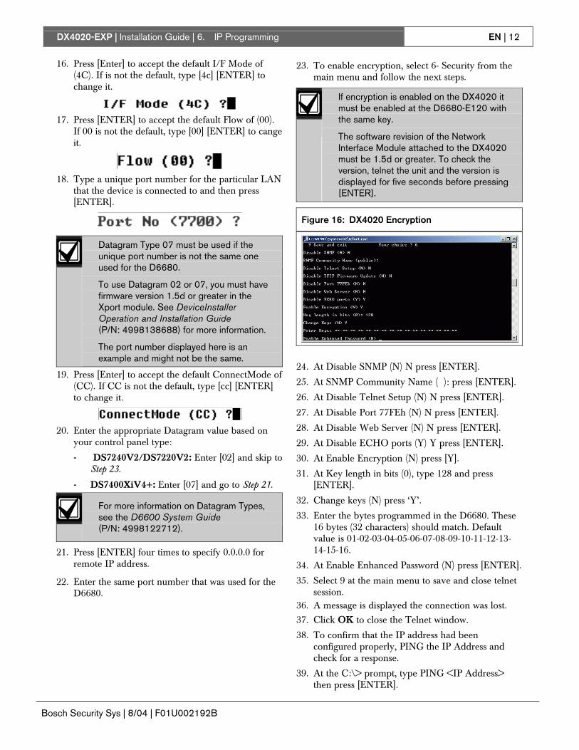
23. To enable encryption, select 6- Security from the main menu and follow the next steps.
If encryption is enabled on the DX4020 it must be enabled at the D6680-E120 with the same key.
The software revision of the Network Interface Module attached to the DX4020 must be 1.5d or greater. To check the version, telnet the unit and the version is displayed for five seconds before pressing [ENTER].
Figure 16: DX4020 Encryption
24. At Disable SNMP (N) N press [ENTER].
25. At SNMP Community Name ( ): press [ENTER].
26. At Disable Telnet Setup (N) N press [ENTER].
27. At Disable Port 77FEh (N) N press [ENTER].
28. At Disable Web Server (N) N press [ENTER].
29. At Disable ECHO ports (Y) Y press [ENTER].
30. At Enable Encryption (N) press [Y].
31. At Key length in bits (0), type 128 and press [ENTER].
32. Change keys (N) press ‘Y’.
33. Enter the bytes programmed in the D6680. These 16 bytes (32 characters) should match. Default value is 01-02-03-04-05-06-07-08-09-10-11-12-13-14-15-16.
34. At Enable Enhanced Password (N) press [ENTER].
35. Select 9 at the main menu to save and close telnet session.
36. A message is displayed the connection was lost.
37. Click OK to close the Telnet window.
38. To confirm that the IP address had been configured properly, PING the IP Address and check for a response.
39. At the C:\> prompt, type PING <IP Address> then press [ENTER].
DX4020-EXP | Installation Guide | 6. IP Programming EN | 13
Bosch Security Sys | 8/04 | F01U002192B
Four reply messages should be received, confirming that the DX4020 is talking to the network.
Configuration of the DX4020 Network Interface Module is complete. Perform this procedure for any additional DX4020’s you may have.
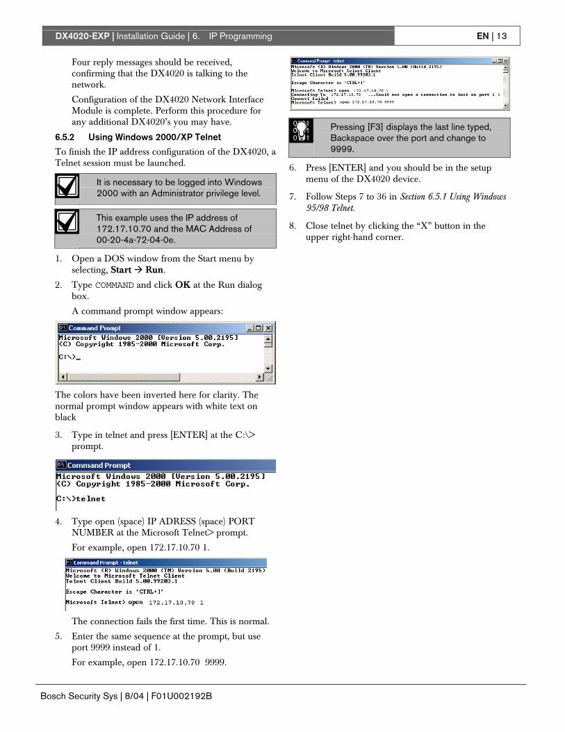
6.5.2 Using Windows 2000/XP Telnet
To finish the IP address configuration of the DX4020, a Telnet session must be launched.
It is necessary to be logged into Windows 2000 with an Administrator privilege level.
This example uses the IP address of 172.17.10.70 and the MAC Address of 00-20-4a-72-04-0e.
1. Open a DOS window from the Start menu by selecting, Start � Run.
2. Type COMMAND and click OK at the Run dialog box.
A command prompt window appears:
The colors have been inverted here for clarity. The normal prompt window appears with white text on black
3. Type in telnet and press [ENTER] at the C:\> prompt.
4. Type open (space) IP ADRESS (space) PORT
NUMBER at the Microsoft Telnet> prompt.
For example, open 172.17.10.70 1.
The connection fails the first time. This is normal.
5. Enter the same sequence at the prompt, but use port 9999 instead of 1.
For example, open 172.17.10.70 9999.
010101010101
Pressing [F3] displays the last line typed, Backspace over the port and change to 9999.
6. Press [ENTER] and you should be in the setup menu of the DX4020 device.
7. Follow Steps 7 to 36 in Section 6.5.1 Using Windows 95/98 Telnet.
8. Close telnet by clicking the “X” button in the upper right-hand corner.
DX4020-EXP | Installation Guide | 7. Control Panel Programming EN | 14
Bosch Security Sys | 8/04 | F01U002192B
7. Control Panel Programming See the control panel’s documentation for DX4020 to control panel programming.
8. Listings and Approvals The DX4020 Network Interface Module is listed for the following:
• FCC Part 15 Radiated/Conducted Emissions
• CE
DX4020-EXP | Installation Guide | Notes EN | 15
Bosch Security Sys | 8/04 | F01U002192B
Notes
© 2004 Bosch Security Systems
Bosch Security Systems 130 Perinton Parkway Fairport, NY 14450-9199 Customer Service: (800) 289-0096 Technical Support: (888) 886-6189 F01U002192B


![Application Package OF GOOD MORAL CHARACTER C.P.R. CARD [Mandatory] STATEMENT OF COMMITMENT INFECTION CONTROL [Signed] DESCRIPTION NUMBER EXP. DATE EXP. DATE EXP. DATE EXP. DATE EXP](https://img.pdfslide.us/doc/110x75/5abd9eef7f8b9a3a428bfa58/application-of-good-moral-character-cpr-card-mandatory-statement-of-commitment.jpg)