Embed Size (px)
Citation preview

ºf º Till º//? B = Diº ºf
- ARBORS AND WORK
HOLDING DEVICES
A TREATISE ON THE APPLIANCES USED FOR
HOLDING WORK FOR TURNING, BORING
AND GRINDING
MACHINERY'S REFERENCE BOOK NO. 120
PUBLISHED BY MACHINERY, NEW YORK

MACHINERY'S REFERENCE SERIES
EACH NUMBER IS ONE UNIT IN A COMPLETE LIBRARY OF
MACHINE DESIGN AND SHOP PRACTIC 7. REVISED AND
REPUBLISHED FROM MACHI '7RY
NUMBER 120
ARBORS AND WORK
HOLDING DEVICES
CONTENTS
Holding Devices for First-operation Work, by ALBERT
A. DOWD - - - - - - - - - - - 3
Arbors for Second-operation Work, by ALBERT A. DOWD 16
Work-holding Arbors and Methods for Turning Opera
tions - - - - - - - - - - - 31
Copyright, 1914, The Industrial Press, Publishers of MACHINERY,
140-148 Lafayette Street, New York City


CHAPTER I
HOLDING DEVICES FOR FIRST-OPERATION WORK
The methods of holding and clamping rough castings for the first or
chucking “operation” are so diversified that the subject must, neces
sarily, be treated by means of examples representing different varieties
of work. Nearly all of the examples shown are more or less cylindrical
in shape, for the reason that elliptical, rectangular, or odd-shaped
parts require special treatment and, therefore, can only be touched
upon in an article of this kind. In the general course of manufactur
ing, there are occasionally pieces of peculiar shape which require
chucking fixtures, but as this work is of such great variety, it is
difficult to give much information regarding its handling except in a
general way. Any piece of work of peculiar shape requires a thorough
knowledge of the conditions governing its use, in order that it may be
chucked properly and located from the surfaces which are of the great
est importance.
Important Points in Design of Chucking Devices
In the design and construction of chucking devices, there are a num
ber of points to which the most careful consideration must be given.
In some cases, the work must be held by the cored interior, as, for ex
ample, an automobile piston, or, in fact, any other work in which it is
necessary to have an equal division of metal throughout the cylindrical
walls. In other instances, however, some method of exterior holding
may be perfectly satisfactory. The term “exterior holding” does not
necessarily mean that chuck-jaws are referred to, for various devices
other than jaws will be cited during the following discussion of hold
ing methods.
Having determined whether the work is to be held externally or in
ternally, let us take up the important points in the design of holding
devices.
First: The important locating surfaces should be carefully con
sidered, always having in mind the future handling of the piece in its
various operations. Great care should be taken that no locating points
are so placed that they will come in contact with the work in places
where the pattern is gated, or where numbers or letters may appear.
Second: In setting up a rough casting there should never be more
than three fixed supporting points; any others which may be necessary
for the proper support of the work must be made adjustable, with some
approved method of clamping securely after adjustment.
Third: The work must be firmly secured so that no distortion can
take place under the strain of clamping.
Fourth: When the work is of such a nature that difficulty is experi
enced in obtaining proper clamping surfaces, it is sometimes advisable
34 7:536

4 . . . . No. 120—ARBORS
to consult with the patternmaker in regard to the addition of clamping
lugs to the pattérn. In cases of this sort, these lugs should be so ap
plied that their subsequent removal can be effected readily.
Fifth : In designing a chucking fixture the safety of the operator
should be considered carefully, and by that is meant that protruding
heads of screws, bolts, clamps and similar parts should be avoided as
much as possible. A little forethought in this regard may be the
means of saving an operator from mutilation or death.
Siarth : Convenience and accessibility in setting, locating and clamp
ing the work, are also of primary importance.
work
2. 2.
C
2. D
|-
2chuck H
º *~ …” NV.
24 on.' SSSSSS 22° 22'N-K > , zº ,
|-M
SSEłer
l
8PECIAL. JAw l
N !
N
Machinery
Fig. 1. (Upper View.) Two-jawed Chuck for holding Piston internally:
(Lower View) Chucking Fixture for Piston Ring Pot
Individual points regarding the work-holding devices shown in the
illustrations will be discussed. We shall consider holding devices for
the horizontal turret or chucking lathe, the vertical turret lathe, and
the vertical boring mill. In describing these devices, the work and
its requirements will be considered, as well as the important locat
ing surfaces, the method of handling the work and important points in
the design of different fixtures.
Two-jaw Chuck arranged for Internal Chucking
It is essential that the cast-iron piston shown in the upper part of
Fig. 1 be located from the cored interior, in order to have the outer
walls concentric with the core, thus obtaining an equal distribution
of metal throughout the piston walls. Due to the formation of this
casting, the core is poorly supported at the closed end and, therefore,
has a tendency to drop slightly when the metal is poured into the

WORK HOLDING DEVICES 5
mold, thereby producing a lack of concentricity between the cored
portion and the exterior surfaces. It is logical then, in order to ob
tain uniform results, to work from the cored portion when setting
up the casting. Many methods of holding have been devised for this
purpose. The fixture shown in Fig. 1 is one of the simplest, an
ordinary two-jaw chuck with special internal jaws being used for hold
ing and locating the work A. A steel bushing B, fastened into the
spindle, contains the stop-rod C, which comes against the head of
the piston, thus insuring a uniform thickness of metal at this point.
The chuck is supplied with the two special jaws D and E. The former
is a plain jaw with two bearing points, while the other has a swivel
jaw F, pivoted on the pin G, which allows it to conform to the in
equalities of the casting. This method of chucking is one of the
cheapest, and the results obtained by its use are fairly satisfactory.
There is a tendency toward inequality in the thickness of the piston
walls in the direction of the Wrist-pin bosses, due to the fact that the
centering action of a chuck of this type is in two directions only;
however, at least one large manufacturer in the East uses this method
entirely. The chuck is employed for rough-turning only, thus secur
ing a partially finished surface which is true with the core and which
may be used to Work from for Subsequent operations.
The work H, shown in the lower view of Fig. 1, is a cast-iron piston
ring pot, which must be held in such a way that it can be bored,
turned eccentrically, and separated into narrow rings for a gas engine
piston. As the ring pot is very thin, it must be carefully held to
avoid distortion and yet be very rigidly secured, as there are several
tools working at one time so that the torsion produced by the cut is
excessive. The pot is made with an internal gripping ring K, which
is slightly beveled to assist in keeping it back against the chuck jaws.
The chuck is an ordinary three-jaw, geared-scroll type, having jaws as
shown in section at N. These jaws are of steel and are drilled to re
ceive the hook-bolts L which pass entirely through them and grip the
ring from the inside. The heads of the bolts M come out through
slots in the jaws, the heel having a backing at O. When setting a
casting the bolts are left free while the jaws are brought up against
the outside of the casting with just enough pressure to get a bearing.
The bolts are then sét up tightly on the gripping ring, so that the
work is held firmly but without distortion. This method is very good
and can be applied successfully to many varieties of thin work. The
hook-bolts are of tool steel and are hardened and drawn to a deep
straw on the hook end. The backing up of the hook-bolt at O is very
important, for unless properly supported at this point its action is
greatly impaired and it soon becomes bent out of shape and is abso
lutely useless.
Ring Pot locating Fixture without Chuck-jaws
Another cast-iron ring pot of somewhat different form is shown in
Fig. 2. The operations on this piece are identical with those for the
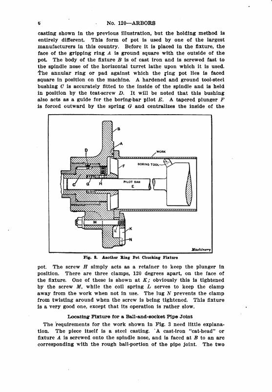
6 - . No. 120–ARBORS
casting shown in the previous illustration, but the holding method is
entirely different. This form of pot is used by one of the largest
manufacturers in this country. Before it is placed in the fixture, the
face of the gripping ring A is ground square with the outside of the
pot. The body of the fixture B is of cast iron and is screwed fast to
the spindle nose of the horizontal turret lathe upon which it is used.
The annular ring or pad against which the ring pot lies is faced
square in position on the machine. A hardened and ground tool-steel
bushing C is accurately fitted to the inside of the spindle and is held
in position by the teat-screw D. It will be noted that this bushing
also acts as a guide for the boring-bar pilot E. A tapered plunger F'
is forced outward by the spring G and centralizes the inside of the
B
A
D WoRK
F BORING Tool.
PILOT BAR
H E
M |
N I K
“I
Machinery
Fig. 2. Another Ring Pot Chucking Fixture
pot. The screw H simply acts as a retainer to keep the plunger in
position. There are three clamps, 120 degrees apart, on the face of
the fixture. One of these is shown at K, obviously this is tightened
by the screw M, while the coil spring L serves to keep the clamp
away from the work when not in use. The lug N prevents the clamp
from twisting around when the screw is being tightened. This fixture
is a very good one, except that its operation is rather slow.
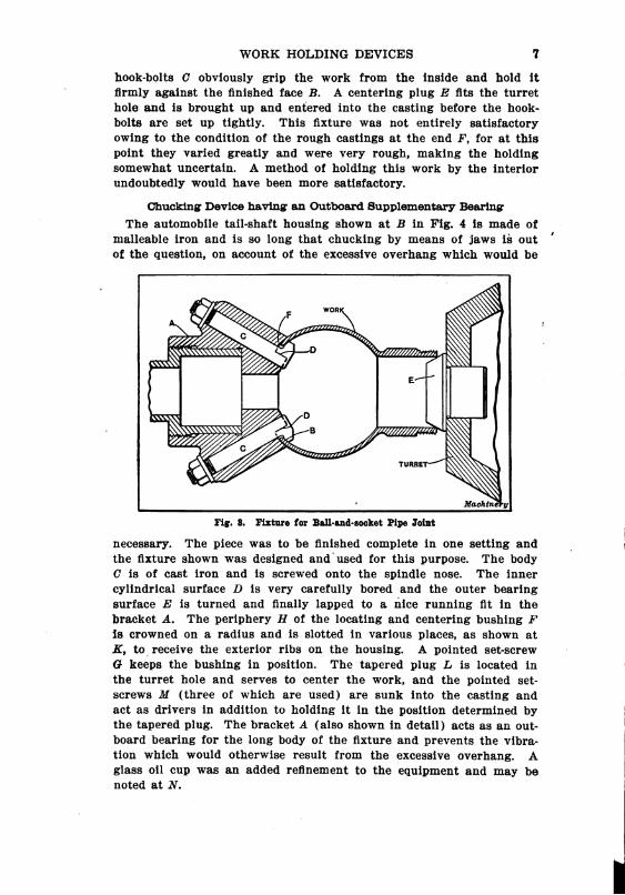
Locating Fixture for a Ball-and-socket Pipe Joint
The requirements for the work shown in Fig. 3 need little explana
tion. The piece itself is a steel casting. A cast-iron “cat-head” or
fixture A is screwed onto the spindle nose, and is faced at B to an arc
corresponding with the rough ball-portion of the pipe joint. The two
WORK HOLDING DEVICES 7
hook-bolts C obviously grip the work from the inside and hold it
firmly against the finished face B. A centering plug E fits the turret
hole and is brought up and entered into the casting before the hook
bolts are set up tightly. This fixture was not entirely satisfactory
owing to the condition of the rough castings at the end F, for at this
point they varied greatly and were very rough, making the holding
somewhat uncertain. A method of holding this work by the interior
undoubtedly would have been more satisfactory.
Chucking Device having an Outboard Supplementary Bearing
The automobile tail-shaft housing shown at B in Fig. 4 is made of
malleable iron and is so long that chucking by means of jaws is out
of the question, on account of the excessive overhang which would be
Fig. 3. Fixture for Ball-and-socket Pipe Joint
necessary. The piece was to be finished complete in one setting and
the fixture shown was designed and used for this purpose. The body
C is of cast iron and is screwed onto the spindle nose. The inner
cylindrical surface D is very carefully bored and the outer bearing
surface E is turned and finally lapped to a nice running fit in the
bracket A. The periphery H of the locating and centering bushing F
is crowned on a radius and is slotted in various places, as shown at
FC, to receive the exterior ribs on the housing. A pointed set-screw
G keeps the bushing in position. The tapered plug L is located in
the turret hole and serves to center the work, and the pointed set
screws M (three of which are used) are sunk into the casting and
act as drivers in addition to holding it in the position determined by
the tapered plug. The bracket A (also shown in detail) acts as an out
board bearing for the long body of the fixture and prevents the vibra
tion which would otherwise result from the excessive overhang. A
glass oil cup was an added refinement to the equipment and may be
noted at N.

8 No. 120–ARBORS
Method of Chucking One-half of a Rear-axle Housing
The male portion of an automobile rear axle housing is shown in
Fig. 5. This is machined in one setting on a horizontal turret lathe.
The body of the fixture B is of cast iron and is screwed onto the nose
of the spindle. Three steel pins C are located 120 degrees apart,
around the inside of the fixture body, the coil springs D forcing them
outward and the set-screws E securing them in place when properly
located against the work. The method of clamping is somewhat
peculiar and should be carefully noted. The swinging dogs F have
a knife-edge at K and are
pivoted on the pins G,
which are set back in
such a position that the
action of the dogs (con
trolled by the hollow set
Screws H) has a tendency
to carry the work back
against the body of the
fixture and the spring
jack pins. A steel bush
ing L is forced onto the
C. D A Small end of the work
H E. and assists in centering
it in the spindle. This
DETAIL OF BRACKET. A
F K B/ bushing is crowned on a
SPINDLE L. radius the same as that
shown in Fig. 4. The
taper locating plunger N
M is forced out by the
Y unre Spring O and is restricted
ways GiB | in its action by the pin
P. The two-arm support
Machinery
Fig. 4. Fixture for holding a Long Part—Outer
End is supported by Bracket
Q is of cast iron and is
of assistance in keeping
the work in position
while the various screws and dogs are being tightened. The bushing
M acts as a guide for the boring-bars and reamers used in machining
the work. The work is driven by the ribs R, which enter slots in the
body of the fixture. This method of holding gave satisfactory results,
although considerable care was necessary to avoid springing the casting
when tightening the clamping dogs.
Equalizing Pin Chuck for a Gas Engine Piston
One of the many varieties of internal holding piston chucks is
illustrated in Fig. 6. Although rather expensive, it is an excellent
example of this type of chuck, and is very well made. All working
parts are of steel or bronze and all parts requiring such treatment are
carefully hardened and ground. The body of the chuck is of ma

WORK HOLDING DEVICES 9
chine steel, carbonized, pack-hardened and ground; the pins, cams,
operating rod, screws and bushings are of tool steel; while the miter
gears are of bronze. The body of the chuck A is screwed onto the
spindle nose and is ground or lapped at all important points. The
operating cams B and C are slotted in three places around the
periphery at D and E, these slots being angular and forcing the six
pins F and G out
against the interior
walls of the piston. It
may be noted that the
steel plates H and K 3 F K
are let into the body of CŞ
the chuck, and act as D
retainers for the pins.
These plates are clearly Q
shown in the upper
view. The operating rod
L is revolved through
the action of the miter
gears M and N. The
latter has a key T en
gaging a long spline in N
the O p e r a ting rod, N
which is thereby per
mitted to move longi
tudinally. The threaded
portion U is 6-pitch
right-hand thread, while
that at V is 6-pitch left- -
hand thread. The for * * *.*.*.*.*.***ward cam is packed
with felt at X to keep out the dirt. The bushing O is of tool steel,
hardened and ground. The plug Q simply closes the hole which has
been put in for assembling purposes.
By referring to the upper view it will be seen that the chuck body
is cut away on the sides at R and S, on account of the wrist-pin bosses
in the piston, and the overhanging lip at R acts as a driver. In design
ing a chuck of this kind, it must be remembered that while the rear
clamping pins may be equally spaced, the position of the forward
pins will be determined by the diameter and spacing of the wrist
pin bosses, and an end view will be found essential to determine the
correct position. In general it will be found that two of the forward
pins seldom can be spaced more than 80 degrees apart and often the
spacing cannot be made more than 55 or 60 degrees. Another point
in design which is of great importance is the amount of clearance
between the ends of the wrist-pin bosses and the flattened sides of the
chuck body. It is seldom safe to allow a clearance of less than 3/16
inch on each side, over the finished sizes called for on the drawing
M/ L N P_d
TuRRET
wORK
Machinery

10 No. 120–ARBORS
of the piston. The location of the stop-pins W is also important, and
sufficient allowance should be made in the length of the cam slots to
take care of variations in the piston castings. A chuck of this type
gives results which are satisfactory in every respect.
An Equalizing Pin Chuck for an Electric Generator Frame
The examples which have been referred to in the foregoing are all
adapted for use on the horizontal type of turret lathe, but we shall
now go a step farther and take up chucking devices designed for the
vertical turret lathe and the vertical boring mill. As machines of
this type are adapted more to heavier classes of Work, the fixtures
M 5. R. "NK G
º,23
- E.
D
T :B I. X
Lºu-|VE||
O P NSJ 2
N --
Q É §: %
7/
Machinery
Fig. 6. Special Chuck for holding Gas Engine Pistons internally
should be designed with relation to the work and also to the power
of the machines upon which they are to be used. For machining the
steel generator frame shown on the fixture in Fig. 7, the working
points specified by the manufacturer are at B between the ribs C on
the upper portion of the casting A. It was further specified that the
work must be held by the core to insure an evenly balanced casting.
The design of this chuck resembles that shown in Fig. 6, in that
both chucks are fitted With pins and operating cams; the operating
mechanism, however, is entirely different. The body of the chuck
D is of cast iron; it is carefully reamed and lapped at important
points, and is securely fastened down to the table of the machine
by three screws having tee-shaped heads, which enter the table T-slots
—UCLJ-TT
Machinery
Fig.7.VerticalBoringMillFixturefor
holdingPartAinternally
Fig.8.
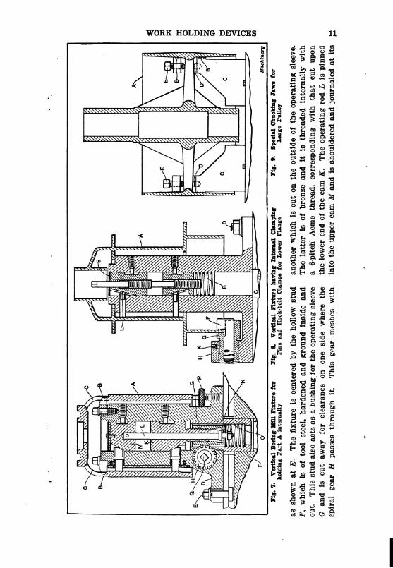
asshownatE.Thefixtureiscenteredbythehollowstud F',whichisoftoolsteel,hardenedandgroundinsideand out.ThisstudalsoactsasabushingfortheoperatingsleeveGandiscutawayforclearanceononesidewherethe spiralgearHpassesthroughit.Thisgearmesheswith
VerticalFixturehavingInternalClamping
PinsandHook-boltClampsforLowerFlange
Fig.9.SpecialChuckingJawsfor
LargePulley
anotherwhichiscutontheoutsideoftheoperatingsleeve. Thelatterisofbronzeanditisthreadedinternallywith a6-pitchAcmethread,correspondingwiththatcutupon thelowerendofthecamK.TheoperatingrodLispinned intotheuppercamMandisshoulderedandjournaledatits
E.

12 No. 120—ARBORS
lower end where it passes through the operating sleeve at N. The
coil spring O is so proportioned that it simply supports the cam
mechanism and assists in releasing. It will be noted that the arrange
ment of this internal mechanism permits a “floating” action for the
cams, so that the clamping pins all bear uniformly against the inner
walls of the casting. In setting up the work on the fixture, it is
dropped over the top until the lower end rests on the three adjusting
jacks P, which are placed 120 degrees apart and are knurled for finger
adjustment. The upper locating arms B are swung back out of the
way while the casting is being set in position, but as soon as this
has been done they are brought around into the position required.
The jacks are next raised until the casting has been properly located
against the arms; then a long-handled socket wrench is inserted at
Q and the gearing is revolved until the pins are securely seated
against the inner Walls of the work.
A Combination Device having Equalizing Pins and Hook-bolts
The piece shown at A in Fig. 8 is a clutch pulley for a gasoline
tractor. It is made of cast iron and the method of holding from the
inside was decided upon because it seemed to offer better facilities for
machining. As in a former example, the body of the fixture contains
the cams and the operating rod which is threaded right- and left-hand,
as before. The lower ends of the pins and the slots in the cams are
dovetailed in this instance, so that the outward and inward movements
are controlled mechanically, no springs or plates being required. The
fixture is centrally located on the machine table by the plug C, which
fits the center hole in the table and is held down in the usual manner
by the T-bolts shown at D. The coil spring B simply acts as a sup
port for the cams and rod. An annular groove is cut in the upper
cam at E and this is packed with felt to assist in keeping the dirt out
of the working parts. The lower part of the fixture has three bosses
(one of which is partially shown at H), which contain the floating
jaws and hook-bolts, G and F, for clamping the lower flange of the
pulley. The construction of these parts is more clearly shown in Fig.
10, and, as they are identical the reader is referred to the portions
marked C and D in that illustration. The results obtained by the
use of this fixture were at first very satisfactory, but, after a time, the
dirt which gradually accumulated in the dovetail cam slots, began to
cause trouble, until, finally, it became almost impossible to operate the
mechanism. Then, too, in several cases the dovetail part broke off
completely, necessitating new pins, so that the chuck as a whole can
not be considered an absolute success. No trouble would have been
experienced if the cam slots and pins had been made as shown in Fig.
7, with coil springs and retaining plates.
A Set of Special Jaws for a Large Crowned Pulley
The large farm engine pulley shown at A in Fig. 9 is of cast iron,
and it must be held by the inside in such a way that it will not be

WORK HOLDING DEVICES 13
distorted while fairly heavy cutting is being done on the periphery
of the pulley. A four-jaw table was selected on which to hold the
work, as there were eight spokes in the pulley. The chuck jaws C
were made of 0.40 per cent carbon steel and were slotted out for the
spokes as shown in the illustration. The hardened steel studs D were
set into the slots, and the set-screws E brought down tightly on them
after the jaw surfaces B had been brought out to center the pulley.
|| |Hºà
w I
x \º o o
\ & \ ||---Él--\ \, L (2)
x V
#SSY O/N
U >> C ** • * 1
N Ž 2R Ø -:
H+\G- K
W. / Ø º-º-V /\\\\\}: V
T
/ H
/2// |/ ,
//; H
/
U C D K
22:22 / r
2% gº l M
- O :\ | 2
|ſ|ºt--L. F
<Z E.
Machinery
Fig. 10. Ingenious Chucking Device for holding Odd-shaped Aluminum
Casting without Distortion
This method of holding pulleys or other spoked work gives very
satisfactory results and is used by many manufacturers throughout
the country.
A Chucking Device for a Difficult Piece of Electrical Work
The aluminum piece shown in Fig. 10 is one of the most difficult for
which there ever is an occasion to make a chucking fixture. The walls
of the entire piece were of very thin section, and the overhanging
portion A was elliptical in shape and entirely unsupported. It was
necessary to so hold this casting that it could be machined Without
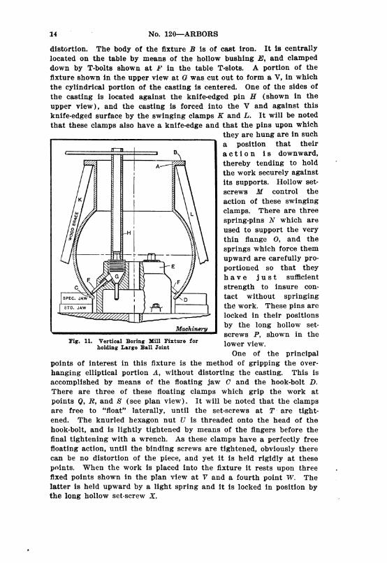
14 - No. 120–ARBORS
distortion. The body of the fixture B is of cast iron. It is centrally
located on the table by means of the hollow bushing E, and clamped
down by T-bolts shown at F in the table T-slots. A portion of the
fixture shown in the upper view at G was cut out to form a V, in which
the cylindrical portion of the casting is centered. One of the sides of
the casting is located against the knife-edged pin H (shown in the
upper view), and the casting is forced into the V and against this
knife-edged surface by the swinging clamps K and L. It will be noted
that these clamps also have a knife-edge and that the pins upon which
they are hung are in such
a position that their
a c ti o n is downward,
thereby tending to hold
the work securely against
its supports. Hollow set
screws M control the
action of these swinging
clamps. There are three
spring-pins N which are
used to support the very
thin flange O, and the
springs which force them
upward are carefully pro
portioned so that they
- h a v e just sufficient
C - // strength to insure Con
SPEC. J.Aw & tact without springingI D
STD. J.AW | ºr the work. These pins are
~2.2|IHC-" locked in their positions
Machinery by the long hollow set
screws P, shown in the
lower view.
One of the principal
points of interest in this fixture is the method of gripping the over
hanging elliptical portion A, without distorting the casting. This is
accomplished by means of the floating jaw C and the hook-bolt D.
There are three of these floating clamps which grip the work at
points Q, R, and S (see plan view). It will be noted that the clamps
are free to “float” laterally, until the set-screws at T are tight
ened. The knurled hexagon nut U is threaded onto the head of the
hook-bolt, and is lightly tightened by means of the fingers before the
final tightening with a wrench. As these clamps have a perfectly free
floating action, until the binding screws are tightened, obviously there
can be no distortion of the piece, and yet it is held rigidly at these
points. When the work is placed into the fixture it rests upon three
fixed points shown in the plan view at V and a fourth point W. The
latter is held upward by a light spring and it is locked in position by
the long hollow set-screw X.
A-T
>
§;
Fig. 11. Vertical Boring Mill Fixture for
holding Large Ball Joint
WORK HOLDING DEVICES 15
The Work accomplished by the use of this fixture was true and ac
curate, no evidence of springing out of true being apparent.
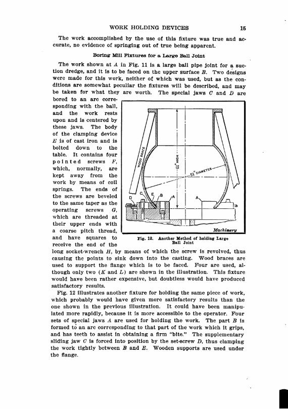
Boring Mill Fixtures for a Large Ball Joint
The work shown at A in Fig. 11 is a large ball pipe joint for a suc
tion dredge, and it is to be faced on the upper surface B. Two designs
Were made for this work, neither of which was used, but as the con
ditions are somewhat peculiar the fixtures will be described, and may
be taken for What they are worth. The special jaws C and D are
bored to an arc corre
sponding with the ball,
and the work rests
upon and is centered by
these jaws. The body
of the clamping device
E is of cast iron and is
bolted down to the
table. It contains four
p o in te d screws F,
which, normally, are
kept away from the
Work by means of coil
Springs. The ends of
the Screws are beveled
to the same taper as the
Operating screws G,
which are threaded at
their upper ends with
a coarse pitch thread, Machievery
and have squares to Fig. 12, Another Method of holding Large
receive the end of the Ban Joint
long socket-wrench H, by means of which the screw is revolved, thus
causing the points to sink down into the casting. Wood braces are
used to support the flange which is to be faced. Four are used, al
though only two (K and L) are shown in the illustration. This fixture
would have been rather expensive, but doubtless would have produced
satisfactory results.
Fig. 12 illustrates another fixture for holding the same piece of work,
which probably would have given more satisfactory results than the
one shown in the previous illustration. It could have been manipu
lated more rapidly, because it is more accessible to the operator. Four
sets of special jaws A are used for holding the work. The part B is
formed to an arc corresponding to that part of the work which it grips,
and has teeth to assist in obtaining a firm “bite.” The supplementary
sliding jaw C is forced into position by the set-screw D, thus clamping
the work tightly between B and E. Wooden supports are used under
the flange.

CHAPTER II
ARBORS FOR SECOND-OPERATION WORK
Cylindrical work which cannot be completely machined in one set
ting and which requires concentricity of the various surfaces obviously
makes necessary some method of holding it for the second operation
which utilizes a previously machined surface for securing the proper
location. When this surface is external, the use of soft jaws, a step
chuck or collet jaws is feasible, but when an internal surface is the
locating point the most efficient method is conceded to be some form
of arbor. This arbor may be either a plain stud made to fit the hole
work
5) [g
WORK
(O)
5||
Machtnery
Fig. 1. Two Types of Expansion Arbors with Split Sleeves
in question, or it may be so designed as to be susceptible of a certain
amount of expansion and contraction in order to take care of slight
variations in the finished hole. The degree of accuracy required in
the finished product determines the form of arbor which should be
used. If a variation of 0.002 to 0.003 inch in concentricity is permis
sible, a plain arbor with some method of driving the work will answer
the purpose very well. When very accurate work is required, however,
greater care must be used in the design, and the expanding type of
arbor is commonly used.

WORK HOLDING DEVICES 17
Inportant Points in Design of Arbors
The fundamental features which tend to make an arbor thoroughly
efficient are as follows: Expansion must be uniform along the entire
periphery; release must be quick and easy; ample driving facilities
must be provided; clamping the work must be effected without chance
of distortion. As an additional refinement, provision may be made
for truing up the arbor so that it will run accurately with the center
line of the spindle.
Lathe Arbors
Let us first consider the arbors designed for use in the engine lathe,
adapted to be held between centers and driven by means of a dog on
one end. The arbor shown in the upper part of Fig. 1 is the simplest
of all those which have a split sleeve or bushing capable of expansion
work
|
Machinery
Fig. 2. Arbor expanded by Internal Taper Plug
or contraction. The mandrel D is slightly tapered and is flattened on
each end to receive the dog for driving. The sleeve C is correspond
ingly tapered and is drilled entirely through at A, after which it is
saw-cut at B is allow for expansion. This arbor is the poorest of all
the expanding types in that the expansion is not uniform, being in
two directions only, and it cannot be depended upon to give results
which are absolutely accurate.
A much better arbor is shown in the lower part of the same illus
tration. It will be noted that the mandrel F, in addition to being
tapered, is threaded on one end to receive the hexagon nut D. This
does away with the necessity of using the arbor press to expand the
sleeve. The collar E is interposed between the nut and the split
bushing. This bushing C is saw-cut at A from one end and at B from
the other, thus allowing a uniform expansion along its entire periphery.
In this connection, it is well to note that the ends of the saw-cuts
should be left tied together until after the sleeve has been hardened
and ground; they can then be cut apart readily with a thin emery

18 No. 120–ARBORS
wheel. An arbor of this kind is mechanically correct and, if carefully
made, should give results which leave nothing to be desired as far as
accuracy is concerned.
Fig. 2 shows an arbor of a very different type, which might be called
a solid expanding arbor. Three holes B are drilled 120 degrees apart
and the saw-cuts A are milled as shown. The special screw E is
tapered at C and threaded at D in the body of the arbor. The end of
this screw is squared and contains the center F. When made as
shown there is nothing in this arbor to commend it. In the first place,
the expansion takes place at one end only and is not at all uniform,
and, in the second place, the center F in the end of the screw cannot
be depended upon to remain true for any length of time, even assum
ing that it may have been made reasonably true to start with, which,
in itself, is a difficult machining proposition.
C
H. H.DETAL OF SHOES
Machinery
Fig. 3. Expanding Arbor of Sliding-shoe Type
The arbor shown in Fig. 3 was at one time manufactured commer
cially by G. E. Le Count, South Norwalk, Conn., but the writer is
unable to state whether it is on the market at the present time or not.
It consists of the body A in which are milled the tapered slots B.
The shoes C (also shown in detail in the upper part of the illustration)
have a narrow rib running along each side and this rib engages with
the grooves in the sides of the slots B, thus preventing the shoes from
falling out. The collar D controls the action of the shoes and is
ground to a sliding fit on the cylindrical portion E of the arbor. It
may be noted that the shoes have two shoulders, thus increasing the
range of the arbor. By providing shoes of various diameters the
range can be increased considerably.
W. H. Nicholson & Co., Wilkesbarre, Pa., manufacture the expand
ing arbor shown in Fig. 9 in various sizes and to suit various con
ditions. The body A is made of tool steel, hardened and ground to a
cylindrical form. The centers are exceptionally large and are care
fully rounded and lead-lapped after hardening. There are four slots
in the body (shown in the Section A-B), and these slots are relieved at

WORK HOLDING DEVICES 19
each corner to prevent any interference by dirt. After hardening,
the slots are also ground to insure truth. The jaws C (also shown in
detail) are made of special steel and carefully ground to the same
taper as the slots. After assembling, they are also ground radially
on their own arbor. The sleeve D acts as a retainer for the jaws and
is a running fit on the cylindrical portion E of the arbor. Four
slots are cut through the sleeve and the jaws are held in position by
them. These arbors are too well known to need further comment, as
they are in general use throughout the country.
Turret Lathe Arbors
We will now go a step further and take up the type of arbors
adapted for use in the horizontal turret lathe. It is well to bear in
Machinery
Fig. 4. Arbor held in Collet and expanded by Internal Taper Plug
mind that arbors of this sort should be so designed that the work may
be easily and quickly put on and taken off without the assistance of
anything more than a wrench or spanner. Every precaution must
also be used in clamping and driving the work, so that no chance for
distortion is possible.
The arbor shown in Fig. 4 is somewhat similar in construction to
that in Fig. 2, except that it is adapted to be held in collet jaws in
stead of On centers, as in the former instance. This arbor gave satis
factory results on the work for which it was used, the surfaces B and
C being faced within the required limits of accuracy. The work was
a push fit on the cylindrical portion D, the expansion taking place at
E, controlled by the tapered screw F. In this case, the nature of the
work permitted a slight margin of error and the expansion was only
necessary to prevent chatter and act as a driver. The shank A is
held in the collet jaws.

20 No. 120–ARBORS
The arbor shown in Fig. 5 was made for the transmission gear which
is shown in position. After the taper hole had been “chucked” in the
work (which was done in a previous setting) the keyway. A was cut
for assistance in driving. The arbor body B is of cast iron, ground to
fit the spindle at C and D. The stem G is of steel, hardened and
ground to fit the body, into which it is keyed to resist the torsion of
the cut. It is held in position and drawn back by the nut and collar
L and M. The forward end is ground to the correct taper E, and the
key is inserted at A. The portion F is threaded with a six-pitch Acme
thread, right-hand, and the nut H is used,to remove the piece after the
work is finished, a piece of drill rod being used in the spanner hole
K to turn the nut. The screw N prevents the body from turning in
the spindle. This arbor has given very satisfactory results.
Machinery
Fig. 5. Taper Arbor mounted in Spindle and equipped with Nut
for removing Work
A somewhat extraordinary condition is shown in Fig. 6, which il
lustrates a steel automobile hub and arbor. In this case, the bearing
seats at A and B were required to be absolutely concentric. In order
to assist in machining, the portion C was bored to size in the first
setting, although no finish was required at this point. The body of
the arbor D is of tool steel, hardened and ground at all important
points. The small end is slotted at three places as shown at F and is
spring tempered at this end. The operating rod K has a very free
thread at H and is ground to a snug running fit in the cylindrical
portion G to insure true running, regardless of the condition of the
threaded part. All the tools used on surface B of the work were
piloted by the stem or extension of rod K, thus securing absolute truth
and concentricity of the ends A and B.
There are several important points to be noted in the construction
of this arbor. First, the method of obtaining a true running stem or

WORK HOLDING DEVICES 21
extension of rod K by means of the long cylindrical bearing at G.;
second, the use of the stem as a pilot for tools, thereby obtaining con
centricity in the two ends of the work A and B; third, the positive
location of One end at A, while using an expansion principle at the
other end to insure rigidity and freedom from chatter. This arbor
was very satisfactory, the two ends being within the extremely narrow
limits of concentricity required.
An entirely different type is illustrated in Fig. 7. This is used for
two different sizes of bronze bearing retainers, the use of adapters
making this feasible. In the construction of this arbor, the body A.
is screwed directly onto the spindle nose, bringing up snugly against
| " || ||
Fig. 6. Arbor with Split Expanding End and Pilot for steadying Tools
the end of the spindle at B. The body itself is of steel and is tapped
out at C to receive the operating screw E. As in Fig. 6, the thread is
a free fit, while the cylindrical portion D is ground to a Snug running
fit to insure concentricity. The bushing F is saw-cut in six places,
three cuts from one end running nearly through, and the other three
in like manner, in order to allow uniform expansion of the bushing.
Both the bushing and the operating screw are tapered correspondingly
at G. The adapter H slips onto the body of the arbor and is located
from shoulder M and secured in place by three screws N. A pin
driver L in the adapter relieves the bushing of excessive strain. The
larger retainer O (shown in detail) is also handled on this same arbor
by using the adapter K. The results obtained with this arbor were
perfectly satisfactory.
22 No. 120–ARBORS
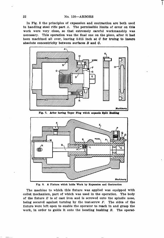
In Fig. 8 the principles of expansion and contraction are both used
in handling steel rifle part A. The permissible limits of error on this
work were very close, so that extremely careful workmanship was
necessary. This operation was the final one on the piece, after it had
been machined all over, leaving 0.015 inch at 0 for truing to insure
absolute concentricity between surfaces B and 0.
Machinery
Fig. 7. Arbor having Taper Plug which expands Split Bushing
Machinery
Fig. 8. A Fixture which holds Work by Expansion and Contraction
The machine to which this fixture was applied was equipped with
collet mechanism, part of which was used in the operation. The body
of the fixture E is of cast iron and is screwed onto the spindle nose,
being secured against turning by the teat-screw F. The sides of the
fixture were left open to enable the operator to reach in and grasp the
work, in order to guide it onto the locating bushing B. The operat
T

WORK HOLDING DEVICES 23
ing rod G was milled at an angle on the forward end H, in order to
force the pin K outward and thus insure rigidity at this point. The
collet operating sleeve M is secured to the rod by pin N, so that the
Collet closing mechanism can be used to operate the rod. At the
forward end of the fixture, the split bushing O is used to center the
Work which is gripped on the finished cylindrical surface D. The bush
ing is knurled at Q and is contracted by the action of the hollow set
screw P. All important surfaces were ground to an accurate fit and
parts subject to wear were hardened. No trouble was experienced
with this fixture and the work was machined within the limits of
accuracy required.
The Steel pinion blank shown at A in Fig. 10 has been previously
faced at B and the taper hole carefully bored, leaving the remainder
of the work to be accomplished at the setting shown. The body C,
in this instance, is of cast iron and is held in position by the teat
screw D. The arbor is of tool steel, carefully hardened and ground.
The shoe E is shaped as shown in the detail above. The operating
rod F is forced inward by screw G, and its release is effected by spring
H which bears against its inner end. It should be noted that the
action of shoe E is both outward and backward; therefore it has a
tendency to force the work back onto the tapered portion. Obviously
key K acts as a driver. In order to avoid any chance of springing the
arbor out of true a small, special wrench is used for turning screw G,
So that too much pressure cannot be applied. The nut L is threaded
On the arbor with a coarse-pitch Acme thread and is of hexagon
shape at the forward end. This nut is used to start the work off the
arbor when the piece is finished. The stem or arbor M enters a bush
ing in the turret and acts as a support while the beveled surface of
the work is being turned. This stem is also used as a pilot for the
face mills which form the end of the pinion at N. This arbor while
used for producing work of the best quality was somewhat fragile and
required careful handling.
The pinion blank shown in Fig. 11 has a straight hole instead of a
taper one, and the arbor for holding it, while somewhat similar in con
struction to that shown in Fig. 10, differs as regards a number of
points. There are three shoes. C, 120 degrees apart, controlled, as to
their outward movement, by the operating rod F. These shoes are re
tained in their positions by the thin circular spring G. The shoulder
H on the arbor acts as a positive longitudinal stop for the work. The
various sectional views give a good idea of the construction. This
arbor is also of tool steel and all important surfaces are hardened and
ground. It gave very Satisfactory results, but the rather delicate
construction necessitated careful handling.
Arbors for Vertical Boring Mill and Vertical Turret Lathe Work
We now come to a class of work of larger size, which can be more
conveniently handled in the vertical boring mill or the vertical turret
lathe. Arbors for comparatively large work frequently develop into

24 No. 120–ARBORS
Machinery
Fig. 9. Expanding Arbor with Sliding Shoes retained in Slotted Sleeve
A
%H'Z o: E K
º T- Ni- 7 ZZ N wº N
\
tºNº
Machinery
Fig. 10. Arbor having Adjustable Shoe E which bears against Taper Bore of Pinion Blank
iT
Machinery
Fig. 11. Arbor for Pinion Blanks, equipped with Three Expanding Shoes

WORK HOLDING DEVICES 25
combination locating and holding devices, so that they are more
nearly related to locating fixtures in the truest sense of the Word. It
is well to remember that in all fixtures of large size some efficient
means of driving the work must be provided, for the thrust of the
tool, incident to the cutting action, is much greater on Work of large
diameter; furthermore, the amount of stock to be removed is usually
considerably more than on smaller work. The fixtures themselves
G
D in Illiullllllllll
Machinery
Fig. 12. Vertical Boring Mill Fixture for holding Bevel Gear—The
Three Shoes L are forced outward by Plug in Center
should also be of exceptional strength and rigidly secured to the table
to prevent movement or breakage.
The large automobile bevel driving gear shown in Fig. 12 is of alloy
steel, and it has been previously bored and faced on the rear side; the
screw holes were also drilled in a jig before placing the gear on the
fixture shown. This fixture was rather expensive, being made entirely
of steel (except the base, which is of cast iron), and all working parts
were hardened and ground or lapped to a perfect fit. The base is

26 No. 120–ARBORS
located in the center of the table by means of the locating stud E, and
is securely fastened down by the three T-bolts B which enter T-slots
in the table. The adjustable part G is held onto the base by the three
screws F. It will be noted that the screw holes have a certain amount
of clearance over the body of the screw to permit adjustments to be
made. The screws and check-nuts at D are for the purpose of con
wRENCH
%
Fig. 13. Flywheel Centering Plug having Vertical Adjustment to
compensate for Slight Variation between Bore and Rim Face
veniently adjusting the fixture. A pin-driver H engages one of the
jig-drilled holes in the work. The upper plate K is square slotted at
three points L to receive the shoes L. The screws M and the dowels
N hold this plate in its proper position. The collar-head screw O
forces down the plunger P on which three angular flat spots are milled.
These angular surfaces control the action of the shoes L and force
them out, uniformly, against the work, thus centering it. The spring
Q Simply aids in releasing the shoes.
Machinery

WORK HOLDING DEVICES 27
This fixture is an exceptionally good one, for in its construction
every care is taken to insure a true-running arbor and one which
can readily be indicated for truth and brought into perfect concen
tricity by means of the adjusting screws. Its action was Satisfactory
in every respect.
Fig. 13 shows an automobile flywheel which has a finished taper
hole and has been turned, bored and faced in a previous setting. It
was essential that the surface A should be concentric with the taper
hole. As it was practically impossible to machine the face of the
flywheel B and the taper hole C so that they would always come in
exactly the same relation to each other, it was necessary to make the
taper plug adjustable in a vertical plane. The base of this fixture is
of cast iron and is located centrally by means of plug D which accur
ately fits into the hole in the table. The base is clamped in position
by three T-bolts E (see plan view) engaging the table T-slots. Three
clamps F are used to clamp the work down on the annular rim G of
the fixture. The plug D not only locates the fixture base, but extends
above the latter and is threaded at H, while above this portion it is
cylindrical and is carefully ground to a running fit in the taper bush
ing K. The threaded portion mentioned is a very free fit, so as to
permit the cylindrical part to do all the centralizing. In using the
fixture, the bushing K is screwed down and the flywheel placed in
position, after which, by the aid of the wrench, the bushing is raised
until it bears in the taper hole. After this, the clamps F are swung
around and tightened. This is a simple fixture, rather inexpensive,
and one which was thoroughly depeñdable.
Fig. 14 shows a cast-iron double-bevel gear used on harvesting ma
chinery, the gear rings A and B having cast teeth. These were not
machined, thus leaving a rough surface by which to clamp the work,
as some support was needed in order to properly machine the annular
ring C. The cylindrical hole D and the end E were machined at a
previous setting.
The cast-iron base of the fixture is centered by the stud F which
fits the center hole in the table. This stud extends up through the
fixture and is tapered at its upper end to receive the split bushing G.
This bushing is saw-cut in six places—three from each end—and is
shouldered at its upper end so that the vertical movement can be con
trolled by the operating screw H. The collar K was pinned in place
after the bushing was slipped over the screw. It will be noted that
the vertical movement of the bushing is entirely mechanical, no
springs being used to effect its release, as in previous instances. The
positive locating point of the fixture is at E, but as it was necessary
to have some support at B the four spring pins L were used; these
bear against the rough surface of the casting and are prevented from
being pushed down by the screws shown. The flat spot against which
the screws bear is milled back at an angle of ten degrees. The rim
of the gear has four cored holes and hook-bolts were necessary for
holding and driving. These are shown at M in the illustration. In
28 No. 120–ARBORS
this connection it is well to note that these hook-bolts are well backed
up by a portion of the fixture N, for a hook-bolt which is not backed
up in some way is worse than useless. This fixture was capable of
rapid manipulation and the results obtained by its use were within
the necessary limits of accuracy.
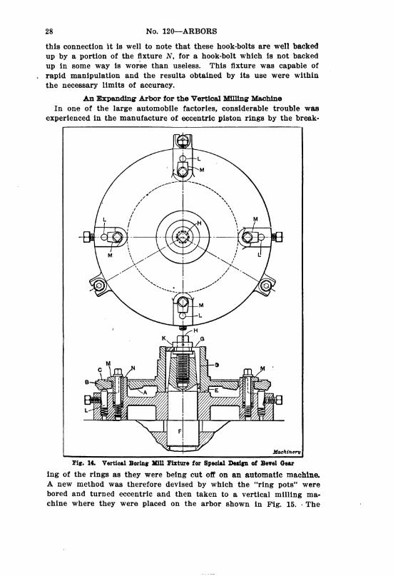
An Expanding Arbor for the Vertical Milling Machine
In one of the large automobile factories, considerable trouble was
experienced in the manufacture of eccentric piston rings by the break
!
Machinery
Fig. 14. Vertical Boring Mill Fixture for Special Design of Bevel Gear
ing of the rings as they were being cut off on an automatic machine.
A new method was therefore devised by which the “ring pots” were
bored and turned eccentric and then taken to a vertical milling ma
chine where they were placed on the arbor shown in Fig. 15. The

WORK HOLDING DEVICES 29
fixture of which the arbor forms a part is located in the center of a
circular milling table by the stud B, and is secured to the table by
means of the three screws A in the T-slots. The stud is tapered at its
upper end to receive the split bushing D, and is secured by the pointed
screw C and prevented from turning by the key E. The bushing was
saw-cut in six places to permit expansion, and was also counterbored
in three places at its lower end to make a pocket for the coil springs
F. These springs tend to make the releasing of the split bushing
easy after the work has been done. The collar G bears on the upper
Machiner”
Fig. 15. Expanding Arbor for holding Casting while Gang-sawing
Packing Rings
portion of the split bushing D and is operated by the screw H which
is threaded into the body of the arbor.
A special arbor K in the spindle of the vertical milling machine was
arranged with a gang of saw cutters properly spaced for the correct
width of ring. As the table is revolved by power feed, the gang of
cutters produce a set of nine clean and unbroken rings. It may be
noted that the split bushing is relieved on its periphery at the points
where the cutters pass through the work, in order to avoid dulling the
cutting edges on the hardened surface. This fixture was made up
very carefully and proved very satisfactory. To the best of the writer's
knowledge, it is still in use although made over six years ago.

|
&
M
Machinery
Fig.16.ArborforcompressingandholdingSplitPackingRingswhilegrinding
AGrindingArborforPistonRings
Theright-handview,Fig.16,showsaneccentricpiston ringforagasenginewhichhasbeenbored,turnedeccentric, groundparallelonthesidesandsplitapartatthepointA.Thearborshowntotheleftinthesameillustrationwas
usedforgrindingtheperipherytomakeitperfectlycylindricalafterithadbeensplitandclosedupatA.Thebody ofthearborBisoftoolsteelwithgenerouscentersineach end.Thesecenterswerelead-lappedafterhardeningand
beforegrindingthecylindricalportion.ThefacesCandDarealsocarefullyground.ThelocatingcollarEisoftool steel,hardenedandgroundtoaverycloserunningfitonthe arborandatthepointHwheretheringsfit.TheportionF isknurledtogiveagoodgrippingsurfaceforthehand whenpullingbackthesleeve.ThespringdetentGserves toholdthesleeveinpositionwhenitispulledbackout ofthewayforgrinding.TheholeKisanairholeandis veryessential,forasthepartsareallverycloselyfittedthe
§

WORK HOLDING DEVICES 31
suction is so great that it is almost impossible to pull back the sleeve
unless this relief hole is drilled. A longitudinal groove along the
arbor would answer the same purpose, but is more likely to catch
dirt and thus cause trouble. The nut N is of tool steel, has a coarse
pitch thread and is made hexagon at the small end. The faces which
bear against the rings are ground parallel with the thread. When in
use, the nut is slipped back out of the way and the two rings M are
sprung into place inside the locating collar after which the nut N is
brought up against the rings and tightened. The locating collar is
then pushed back out of the way, until the detent snaps into place,
and the work is then ready for the grinding operation on the
periphery. Arbors of this type are in daily use in nearly all of the
automobile factories in this country.
The various types of arbors and fixtures illustrated and described
in this article cover representative work of nearly all kinds, and may
be modified to suit almost all possible conditions whether they affect
the work part, the machine, or both, -
CHAPTER III
WORK-HOLDING ARBORS AND METHODS FOR
TURNING OPERATIONS
The developments in the design of machine tools during the last
ten or fifteen years have brought these machines to a high degree of
perfection. Many are provided with features which make great pre
cision possible, and a workman who understands how to get the most
out of one of these modern machine tools can produce very accurate
work. It should be remembered, however, that no matter how accur
ate and how well adapted to rapid production the machine may be, if
the methods of holding the work are not equally well thought out
there is comparatively little gained. As a matter of fact, this point
is neglected in a great many machine shops. In a few instances, we
find planning departments and efficient tool-designing departments
where the methods and appliances to be used in manufacturing are
carefully considered. In the majority of shops, however, the work
men, or at least the foremen, are left to devise for themselves the
methods by which the work is to be held in the machines. In the few
cases where the workman is unusually ingenious, this may be of ad
vantage, but it is seldom possible for the man at the machine to con
sider both the accuracy required and the rapidity of production with
anything like the care that can be done by a designer especially de
tailed to do this work.
Therefore, it is becoming generally recognized that in order to
take advantage of the full capacity and adaptability of modern ma

32 No. 120—ARBORS
chine tools, it is necessary that the work-holding and machining
methods be worked out by designers of equal ability to those who actu
ally design the machine. In the following a few methods will be
shown for holding different classes of work for turning and facing
operations in the lathe. The arbors and devices shown were designed
at the Jones & Lamson Machine Co., Springfield, Vt., for use in the Fay
automatic lathe; but as far as the methods for holding the work are
concerned, they may be employed with equal advantage in any engine
lathe, and are therefore capable of wide application. The tooling ar
rangements shown in each case are, of course, especially adapted to
::
Machinery
Fig. 1, Rear View of Head End of Fay Automatic Lathe
the Fay automatic lathe with its front and rear tool-holders, but by
means of a special tool-block many engine lathes could be rigged up
to perform the work in a similar manner. These tooling arrange
ments will probably suggest other machining methods.
Principles of Arrangement of the Fay Automatic Lathe
In order to make the following article intelligible in so far as the
arrangement of the tools is concerned, 1t will be necessary to refer
briefly to the construction of the Fay automatic lathe. The line en
graving Fig. 1 shows a rear view of the head end of the machine; Fig.
2 shows a sectional view. The main or work-spindle is driven by
worm gearing from a cone pulley mounted at right angles to it. A
series of cams is provided for controlling the cutting tools, and by
means of a clutch mechanism operated by adjustable dogs, the cam.

WORK HOLDING DEVICES 33
shaft may be given a slow feeding movement or a rapid idle move
ment over any portion of the periphery of the cam. Two heavy bars,
A and B, extend the full length of the machine and on these the vari
ous carriages and tool-holders are mounted. Each of these bars is
controlled by a cam both as regards the longitudinal and the rock
ing movement about their axes. The rocking movement of the front
tool-holder C is caused by templets or cam surfaces on the slide or
former bar at the front of the bed on which the outer end of the car
riage rests. These templets may be given any desired shape which will
be copied by the tool as the carriage is fed longitudinally. The car
Machinery
Fig. 2. Cross-sectional View of Fay Automatic Lathe
riage may also be held stationary and the former bar carrying the
templet may be fed to the right or left, thereby causing the tool to
feed directly in or out at right angles to the axis of the work. The
main tool bar is operated longitudinally by an internal cam surface
within the cam drum shown to the right in Fig. 1, and the tool slide
at the rear 1s rocked by a cam beneath the headstock. It will be
understood from this description that the front tool-block C is especi
ally adapted to straight turning, taper turning and forming operations,
while the rear tool-holder D is intended for operations requiring the
tool to be fed in toward the center of the work after which, of course,
the tool-bar can be fed longitudinally for ordinary straight turning
operations.

34 No. 120–ARBORS
Arbors for Holding Bushings made in Halves
The arbor shown in Fig. 3 is used for holding the type of half-bush
ings illustrated while turning the outside. When performing this
operation, it is necessary that the bushings be so held that the part
ing line comes exactly in the center, so that the two halves are inter
changeable. At the same time, they must be held so that the outside
will be true with the inside, which has already been finished by a
formed convex milling cutter. When the inside has been finished, the
two halves are clamped to an arbor and the ends are finished to a
beveled surface by a hollow mill. The half-bushings are then ready
to be placed on the arbor shown in Figs. 3 and 5, where they are held
in place by beveled collars slightly corrugated on the tapered surfaces
to form an effective drive. By holding the bushings in this manner
Fig. 3. Half-bushings to be machined and Arbor used for holding
them while turning Outside
the whole of the outside can be finished at one setting. The rear tool
block carries the roughing tools and is first fed inward in the direc
tion of arrow A, Fig. 5, and then to the left in the direction of arrow
B. The roughing cut is divided between the tools C, D, N and O, so
that the tool slide needs to feed from E to F only in order to complete
the roughing cut. The tool N roughs out the top of the shoulder on
the bushing, while the tool O roughs out the part of the bushing to
the right of the shoulder.
The finishing tools are held in the front tool-holder. Tool H is first
fed in the direction of arrow G, finishing one end of the bushing, and
then tool K is fed in the direction of arrow L to finish the other end
of the bushing; at the same time, tool M finishes the collar or shoulder
shown. The roughing is entirely completed before the finishing cut
begins. The finishing cut on the long surface to the left on the bush
ing is done by one tool K and not by two tools as in the case of the
roughing cut, because if two tools were used for finishing it would be

WORK HOLDING DEVICES 35
difficult to avoid a slight mark on the turned surface at the point
where the two cuts meet. Fig. 4 shows the work and tools as ar
ranged in the machine.
In Fig. 6 is shown an arbor used for holding a tapered bushing
while finishing the outside; the bushing is shown in Fig. 7, and Fig.
8 shows the work and tools sets up in the machine. In this case the
hole in the bushing, which is made in halves as in the preceding case,
is rough. The joint between the two halves must, however, come
exactly in the center of the finished bushing so that the two halves'
may be interchangeable. The first operation is to plane the joints;
then the two halves are clamped together and the ends are finished
by a hollow mill to form a bevel bearing for the clamping collars of
the arbor. When milling the ends, the joint must be held central in
Fig. 4. Tools illustrated in Oetail in Figs, 3 and 5 set up on Fay
- Automatic Lathe
a jig especially designed for the purpose. The half-bushing is then
clamped on the arbor shown in Fig. 7, the beveled surfaces of the
collar and shoulder holding it true. Fig. 6 shows the arrangement of
the roughing tools, the arrows indicating the direction in which they
are fed. The front and rear tools are in action simultaneously. The
front tools are guided by a taper former on the former bar. In the
roughing operation the Small surface at A will, of course, be turned
on a taper, but this will be corrected by the finishing operation, the
tooling arrangement for which is shown in Fig. 9. In this case the
tools in the back tool-holder finish the short taper on the shoulder and
the top of the projection. The long taper surface of the bushing is
finished by the tool held in the front tool-holder. Arrangements are
made for relieving the tool on the return.
Fig. 10 shows another tapered bushing made in halves, which is
turned on the outside before the inside is finished. Here the ends
are not finished because other means are available for holding the

36 No. 120–ARBORS
Work So as to locate the joint in the center of the finished bushing.
There are lugs on the inside of one of the half-bushings, which bear
against shoulders on the arbor, as shown by the section to the left.
After the two halves are finished by planing, the half provided with
the lugs is first placed on the arbor so that the lugs bear against these
-
——
Machinery
Fig. 5. Tool Arrangement for turning Half-bushings shown in Fig. 3
Jºº----,*Y--
Øzz->% %34/4-4-22%%%
iſ, % %2% **-44.2%
~~~~~~~~zz -- >z.
%2%ºzz- zz ^zz z-z-z-
ºØ---/
º,
Machinery
Fig. 6. Method of holding Tapered Bushings shown in Fig. 7
shoulders, which insures a correct location. As the ends are rough,
the clamping arrangements must be made to take care of any adjust
ment necessary to provide a full bearing. A bushing C is therefore
provided within which slide two half-bushings D, operated by adjust
ing screws. By means of these screws each half of the bushing to be
turned can be clamped tightly against the collar at the other end of
WORK HOLDING DEVICES 37
the arbor; at the same time the joint in the center will be held in
correct relation to the center of the arbor. The roughing cut is
divided between the two tools in the rear tool-holder and the finishing
is done by the tool in the front tool-holder. Only the short surface
from E to F is finished.
Zºº
Fig. 7. Arbor for turning Tapered Bushings and Work for which it
was designed
º
Fig. 8, Tools shown in Detail in Figs, 6 and 7, set up on Fay
Automatic Lathe
Holding Work with Square Holes
A piece of work with a square broached hole by which the piece is
held on a square arbor is shown in Fig. 11. In this case the cutting
is all done in one direction so that it is unnecessary to provide for
clamping the work for endwise motion. An illustration of the piece
38 No. 120—ARBORS
of work and the arbor, also showing the work in place on the arbor,
is given in Fig. 12. The tools, as inserted in their respective holders,
are shown in place on the machine in Fig. 14.
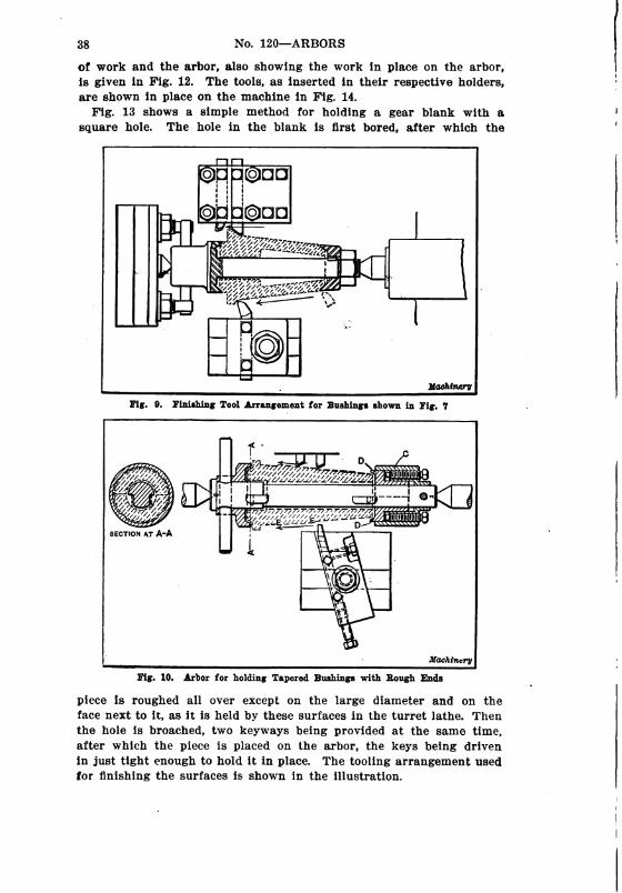
Fig. 13 shows a simple method for holding a gear blank with a
square hole. The hole in the blank is first bored, after which the
Machinery
Fig. 9. Finishing Tool Arrangement for Bushings shown in Fig. 7
Žiš.Zºś
77/7.
22.2%%22z/Z
~~~~~~~~~~~~ غHzz Zº:%22%2%ZZZZZZZZZZZZZZZZZ.4%f ſºØg%2.É222 FT, TTD %iáſ C
4. -e
SECTION AT A-A
Machinery
Fig. 10, Arbor for holding Tapered Bushings with Rough Ends
piece is roughed all over except on the large diameter and on the
face next to it, as it is held by these surfaces in the turret lathe. Then
the hole is broached, two keyways being provided at the same time,
after which the piece is placed on the arbor, the keys being driven
in just tight enough to hold it in place. The tooling arrangement used
for finishing the surfaces is shown in the illustration.

WORK HOLDING DEVICES 39
When a piece of work is to be finished on the Fay automatic lathe,
or in any lathe with multiple tools and fixed stops, it is necessary
that the endwise location of the work be always the Same; hence When
F.F-1
CGC
work bCC
I ! square work
> l -- -r o
i
i :
ARBoR
|
&
Fig. 11, Turning Work carried on Arbor passing through Square
Broached Hole
direction
OF FEED
KºG)| " |
| | ||
| | ||
| | | ||
idó, a|-
|
Machinery
work with a round hole is to be finished, it cannot be held on an
ordinary arbor with a slight taper unless the hole is so accurately
finished that the piece will come to a driving fit at a given place on
Fig. 12. Square Arbor for carrying Work with a Square Broached
Hole
the arbor, in which case the point to which the work is to be driven
may be determined by means of a simple gage which acts as a stop.
As a matter of fact, some firms make it a point to machine the holes
in work of this kind so accurately that the work can be driven onto
40 No. 120–ARBORS
an arbor and come to a driving fit at a given point. This can almost
always be done with bronze bushings, as there is enough elasticity in
this material to permit the pieces to be forced down to a certain po
sition. With this method of holding, both ends of the work can be
faced, as there are no clamping arrangements to obstruct the path of
the tools.
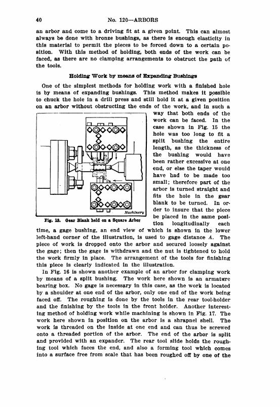
Holding Work by means of Expanding Bushings
One of the simplest methods for holding work with a finished hole
is by means of expanding bushings. This method makes it possible
to chuck the hole in a drill press and still hold it at a given position
on an arbor without obstructing the ends of the work, and in such a
— - Way that both ends of the
[] - WOrk can be faced. In the
TTI
- case shown in Fig. 15 theQQQQQQ g
hole was too long to fit a
Split bushing the entire
—N OCKPOGO length, as the thickness of
the bushing would have
been rather excessive at one
end, or else the taper would
have had to be made too
Small; therefore part of the
arbor is turned straight and
fits the hole in the gear
blank to be turned. In or
der to insure that the piece
be placed in the same posi
tion longitudinally each
time, a gage bushing, an end view of which is shown in the lower
left-hand corner of the illustration, is used to gage distance A. The
piece of work is dropped onto the arbor and secured loosely against
the gage; then the gage is withdrawn and the nut is tightened to hold
the work firmly in place. The arrangement of the tools for finishing
this piece is clearly indicated in the illustration.
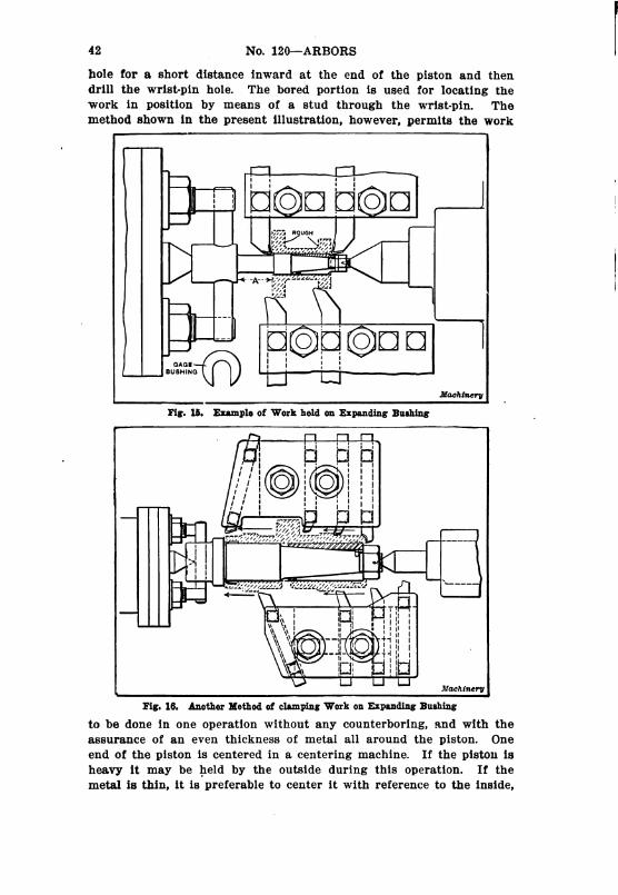
In Fig. 16 is shown another example of an arbor for clamping work
by means of a split bushing. The work here shown is an armature
bearing box. No gage is necessary in this case, as the work is located
by a shoulder at one end of the arbor, only one end of the work being
faced off. The roughing is done by the tools in the rear tool-holder
and the finishing by the tools in the front holder. Another interest
ing method of holding work while machining is shown in Fig. 17. The
work here shown in position on the arbor is a shrapnel shell. The
work is threaded on the inside at one end and can thus be screwed
onto a threaded portion of the arbor. The end of the arbor is split
and provided with an expander. The rear tool slide holds the rough
ing tool which faces the end, and also a forming tool which comes
into a surface free from scale that has been roughed off by one of the
Machinery
Fig. 13. Gear Blank held on a Square Arbor

WORK HOLDING DEVICES 41
tools in the front slide. The direction of the cut of the tools in the
front slide, first inward, then parallel, and then slightly outward, is
shown by the arrow. Fig. 18 shows the arrangement of the tools for
roughing and finishing the tapered end of the shell and for knurling
a groove at the closed end. In this case a special grooved former
must be used in place of the taper attachment of the machine at the
rear. When the front tool at the left has completed its cut the finish
ZººZºº
Fig. 14. Turning Work carried on a Square Arbor in a Fay
Automatic Lathe
ing tool-holder drops in, permitting the tool to the right to perform
the knurling operation. In this case a former is clamped to the former
bar of the machine.
Supporting Thin Work from the Inside
The most interesting holders for work that is to be machined in
the lathe are, perhaps, those that are arranged to support thin work
from the inside. In Fig. 19 is shown one example of a piston held by
an equalizing arrangement. This arrangement is applicable only to
pistons which are not to be ground. The usual method is to bore a
42 No. 120—ARBORS
hole for a short distance inward at the end of the piston and then
drill the wrist-pin hole. The bored portion is used for locating the
work in position by means of a stud through the wrist-pin. The
method shown in the present illustration, however, permits the work
| 1 T I
| I ; :
} |C(O)C C(O)C|
l |-4 S-4 N. Z
-
Ø-" Nº.(22. z
~~~~Z/2 -
i’z, 2. N —*Z-21
N. Z.
+ 1
|- | ! I
GAGE | | |
BUSHING T] UT
Fig. 15. Example of Work held on Expanding Bushing
Machinery
T Fl—Fl| | | i.
%22%
--~ %2
zzºzzº.
2 lay ---
3.273rºſ....)zzzzzzzzzzzzz
Machinery
Fig. 16. Another Method of clamping Work on Expanding Bushing
to be done in one operation without any counterboring, and with the
assurance of an even thickness of metal all around the piston. One
end of the piston is centered in a centering machine. If the piston is
heavy it may be held by the outside during this operation. If the
metal is thin, it is preferable to center it with reference to the inside,

WORK HOLDING DEVICES - 43
holding the work in a jig like the fixture used in the machine. The
holding device consists of three plungers A at each end of the piston,
which slide in slots cut in the head of bolt B and in collar C, and
which thus both center the work and support it on the inside. In the
case of Small pistons only two plungers are used at the closed end,
Machinery
Fig. 17. Combination Threaded and Expanding Arbor for holding
Shrapnel Shell in Lathe
95%azzzzzzzzzzz-z-z- 2.
*3222.2%;4%
%
%3%
Lºz727%ZZZZZZZZZZZZZA
2.4% 2^3~~~~<
Machinery
Fig. 18. Tool Arrangement for turning Shrapnel Shell Point and
knurling Groove at Closed End
because there is not enough room for three on account of the bosses
for the wrist-pin. The bolt with the tapered slot is tightened by means
of a nut having a slot in it, which can be reached from the end of the
arbor when the fixture is taken out of the machine, by means of a
special screwdriver. The tooling arrangement shown in the illustra
tion is that provided for roughing the piston. The two tools in the

44 No. 120—ARBORS
front holder divide the roughing cut between them so that the feed
motion needs to be only one-half of the length of the piston.
Fig. 20 shows a method used for supporting the overhanging rim of
a long pulley. In this case the pulley is centered by the hole which
fits the arbor, and the support must simply act as an equalizer. As will
be seen, two floating collars A and B are provided which are tapered
on one side. This tapered side bears against pins C and D. As the
collars are perfectly free to locate themselves with relation to the
arbor, it is evident that the pressure on the pins (of which there are
three for each collar) will be the same, and there will be no tendency
oo::#5
oğ.
$ººl-º--
%NS Žº ºzº –
goºoodMachinery
Fig. 19. Arbor for holding Pistons to be turned
to throw the work out of center, but to merely support it with equal
pressure at the six bearing points.
Holders for TWO Pieces of Work
In many instances it is possible to hold two pieces on the same
arbor, thus practically cutting the time of machining in half. The
simplest illustration of this is probably that shown in Fig. 21, where
two gear blanks, which have been faced on One side and have had the
holes bored, are clamped together and faced on the other side and
turned on the outside. The arrangement of the tools is of interest;
the arrows shown give the direction of the feed and indicate the
method of procedure. Fig. 22 shows another case where two pieces
held on the same arbor are machined at the same time. A spacer is
provided between the two pieces so as to locate the one to the right in

WORK HOLDING DEVICES
©CCCCC •
Machinery
Fig. 20. Method of supporting Pulley from Inside while turning
finishing
lºſ
~~->R S.
§; IM
i&§Ks'NROUGHING
Toolº->>S.>>>
º C©O
Machinery
Fig. 21. Example of Arbor designed to hold Two Pieces of Work
at One Time
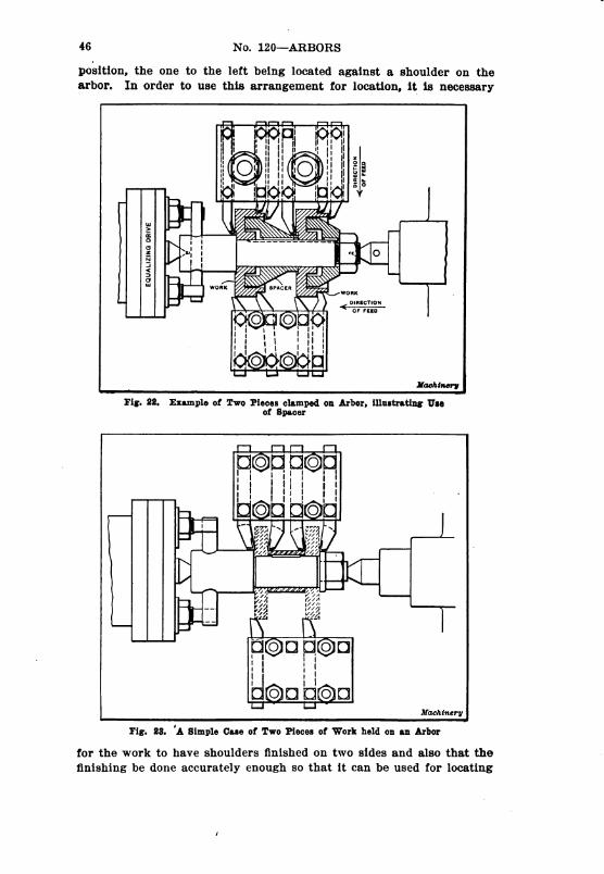
46 No. 120—ARBORS
position, the one to the left being located against a shoulder on the
arbor. In order to use this arrangement for location, it is necessary
i ;
|work SPACER
Work
direcTion
Gºodó "
gogogU-J
hMachinery
Fig. 22. Example of Two Pieces clamped on Arbor, illustrating Use
of Spacer
©d O
%i
•
i.l)
/1
-- 2 zzz —
Machinery
Fig. 23. 'A Simple Case of Two Pieces of Work held on an Arbor
for the work to have shoulders finished on two sides and also that the
finishing be done accurately enough so that it can be used for locating

woFK HOLDING DEVICEs. .. . . . .''.
the two pieces. In this case both the clamping collar and the spacer
are keyed to the arbor to make the drive more positive.
In Fig. 23 is shown another case of clamping two pieces using a
spacer between them. It is evident that if the two sides of the hubs
of the gear blanks had not previously been machined, this method
could not be used as the gear blank to the right would not come in
an accurate position to permit being machined by the tooling arrange
ment indicated.
In Fig. 24 is shown still another example of holding two pieces by
means of a spacer. Here the roughing and finishing are done at the
same time. The tools in the rear and front holders operate simultane
Machinery
Fig. 24. Another Example of Use of Spacer between Two Pieces
ously, the taper attachulent being used for the rear holder. A taper
former is used on the former bar for the front tool-holder. Fig. 25
shows an especially interesting arrangement for holding two pieces
and for supporting the thin walls of the bushings while machining.
In this case the ends and the inside of the bushing are rough. The
only difficulty that was met with was to machine them without dis
torting them on account of the thinness of the metal. The bushings
are both centered and supported by the rough inside surface. For this
purpose bushings B are provided on the arbor. These bushings hold
plugs C which are prevented from falling out of their seats by springs
when the pieces to be machined are to be removed from the arbor.
The arbor itself is provided with three flat spots or bearings, as shown
in the sectional view at the top. These act as cam sufrfaces when the

-
, -, * * *
48 . . . . . . . . No. 120–ARBORs- -
arbor is turned and force the plugs outward, thereby centering and
supporting the work on the inside. This arbor shows a different
method than those shown in the previous examples for holding two
pieces at once. Here the middle portion of the arbor is solid and
~~~~~
A SECTION AT A-A
ZŽ Ž
Fig. 25. Arbor for holding Two Pieces of Work which must be
supported from the Inside
provided with three bearing points on each side for the work. Then
collars are provided at each end of the arbor with nuts for clamping
the work. One disadvantage is present with this arbor. The dog at
the driving end must be removed to take off the pieces nearest to the
head. In practically all the other cases shown a driving pin driven
into the arbor can be used, as the work is removed in the other
direction.


MACH IN ERY'S
H A N D B O O. K.
For MACHINE SHOP
AND DRAFTING-ROOM
A REFERENCE BOOK ON MACHINE
DESIGN AND SHOP PRACTICE FOR
THE MECHANICAL ENGINEER,
DRAFTSMAN, TOOLMAKER AND
MACHINIST.
MACHINERy’s Handbook comprises nearly 1400 pages of carefully edited and
condensed data relating to the theory and practice of the machine-building
industries. It is the first and only complete handbook devoted exclusively to
the metal-working field, and contains in compact and condensed form the
information and data collected by MACHINERY during the past twenty years.
It is the one essential book in a library of mechanical literature, because it
contains all that is of importance in the text-books and treatises on mechanical
engineering practice. Price $5.00.
GENERAL CONTENTS
Mathematical tables-Principal methods and formulas in arithmetic and algebra
Logarithms and logarithmic tables—Areas and volumes—solution of triangles and
trigonometrical tables-Geometrical propositions and problems-Mechanics-strength of
materials-Riveting and riveted joints—Strength and properties of steel wire-strength
and properties of wire rope—Formulas and tables for spring design-Torsional strength
-Shafting-Friction–Plain, roller and ball bearings—Keys and keyways–Clutches and
couplings—Friction brakes—Cams, cam design and cam milling—spur gearing—Bevel
gearine-Spiral gearing-Herringbone gearing—Worm gearing—Epicyclic gearing–Belting
and rope drives—Transmission chain and chain drives—Crane chain-Dimensions of small
machine details—Speeds and feeds of machine tools-Shrinkage and force fit allowances
Measuring tools and gaging methods—Change gears for spiral milling-Milling machine
indexing-Jigs and fixtures-Grinding and grinding wheels—screw thread systems and
thread gages-Taps and threading dies—Milling cutters—Reamers, counterbores and
twist drills-Heat-treatment of steel—Hardening, casehardening, annealing—Testing the
hardness of metals—Foundry and pattern shop information—The welding of metals—
Autogenous welding-Thermit welding-Machine welding-Blacksmith shop information
-Die casting-Extrusion process—soldering and brazing–Etching and etching fluids—
Coloring metals-Machinery foundations—Application of motors to machine tools-Dynamo
and motor troubles-Weights and measures—Metric system—Conversion tables—Specific
gravity-weights of materials—Heat—Pneumatics–water pressure and flow of water—
Pipes and piping-Lutes and cements—Patents.
-
Macºnrºy, the leading journal in the machine-building field, the originator
of the 25-cent Reference and Data Books. Published monthly. Subscription,
$2.00 yearly. Foreign subscription, $3.00.
THE INDUSTRIAL PRESS, Publishers of MACHINERY
140-148 LAFAYETTE STREET NEW YORK CITY, U. S. A.
|-