Embed Size (px)
Citation preview
03 02 10
CONCRETE CURING MATERIALS 2.10 CURING MATERIALS
A. Evaporation Retarder: Waterborne, monomolecular film forming, manufactured for application to fresh concrete 1. Available Products:
a. Conspec Marketing & Manufacturing Co., Inc., a Dayton
Superior Company; Aquafilm. b. Dayton Superior Corporation; Sure Film. c. Euclid Chemical Company (The); Eucobar. d. L&M Construction Chemicals, Inc.; E-Con. e. Meadows, W.R., Inc.; Sealtight Evapre. f. Sika Corporation, Inc.; SikaFilm. g. Symons Corporation, a Dayton Superior Company; Finishing
Aid B. Absorptive Cover: AASHTO M 192, Class 2, burlap cloth made from jute or Kenaf, weighing approximately 9 oz. /sq. yd. when dry.
C. Moisture-Retaining cover: ASTM C 171, polyethylene film or white burlap-polyethylene sheet.
D. Water: Potable.
E. Clean, Waterborne, Membrane-Forming Curing Compound: ASTM C 309,
Type 1, Class B, dissipating.
1. Available Products:
a. Anti-Hydro International, Inc.; AH Curing Compound #2 DR WB.
b. Conspec Marketing & Manufacturing Co. Inc. a Dayton Superior Company; W.B. Resin Cure.
c. Dayton Superior Corporation; Day Chem Rez Cure (J-11-W).
d. Euclid Chemical Company (The); Kurez DR VOX. e. L&M Construction Chemicals, Inc.; L&M Cure. R. f. Meadows, W.R., Inc.; 1100 Clear. g. Symons Corporation, a Dayton Superior Company; Resi-
Chem Clear Cure.
Elderly Apartment 11/21/06 03 02 10 - 1 Concrete Curing Materials
F. Clear, Waterborne, Membrane-Forming Curing and Sealing Compound: ASTM C 1315, Type 1, Class A.
1. Available Products:
a. Conspec Marketing & Manufacturing Co., Inc., a Dayton
Superior Company; Sealcure 1315 WB b. Euclid Chemical Company (The); Super Diamond Clear
VOX. c. L&L Construction Chemicals, Inc.; Lumiseal WB Plus. d. Meadows, W.R., Inc.; Vocomp-30. e. Symons Corporation, a Dayton Superior Company; Cure
& Seal 31 Percent E.
Elderly Apartment 11/21/06 03 02 10 - 2 Concrete Curing Materials
Elderly Apartment / 04-28-06 03 05 00 - 1 Concrete
SECTION 03050 CAST-IN-PLACE CONCRETE
PART 1 GENERAL
1.01 SECTION INCLUDES
A. Mortar for unit masonry and stone veneer.
1.02 RELATED SECTIONS A. Fibrous Reinforcement: Section 03240.
B. Vapor Barrier Under Slabs on Grade: Section 072611.03 REFERENCES
A. Except as shown or specified otherwise, the Work of this Section shall conform to the requirements of Specifications for Structural Concrete for Buildings ACI 301-99 of the American Concrete Institute.
1.04 SUBMITTALS A. Submittals Package: Submit product data for design mix(es) and materials for
concrete specified below at the same time as a package.
B. Shop Drawings: Placing drawings for bar reinforcement.
C. Product Data: 1. Concrete design mix(es) with name and location of batching plant. 2. Portland Cement: Brand and manufacturer’s name. 3. Fly Ash: Name and location of source, and DOT test numbers. 4. Air-entraining Admixture: Brand and manufacturer’s name. 5. Water-reducing Admixture: Brand and manufacturer’s name. 6. Aggregates: Name and location of source, and DOT test numbers. 7. Lightweight Coarse Aggregate: Brand and manufacturer’s name
8. Chemical Hardener (Dustproofing): Brand and manufacturer’s name, and application instructions.
9. Chemical Curing and Anti-Spalling Compound: Brand and manufacturer’s name, and application instructions.
10. Bonding Agent (Adhesive): Brand and manufacturer’s name, and preparation and application instructions.
11. Expansion Joint Filler: Brand and manufacturer’s name. 12. Emery Aggregate: Brand and manufacturer’s name, and application
instructions. D. Samples: 1. Fabric Reinforcement: 8 inches square. 2. Bar Supports: Full size. E. Quality Control Submittals: 1. Certificates: Affidavit required under Quality Assurance Article.
Elderly Apartment / 04-28-06 03 05 00 - 2 Concrete
1.05 QUALITY ASSURANCE A. Concrete batching plant shall be currently approved as a concrete supplier by the
New York State Department of Transportation.
B. Fly ash supplier shall be currently approved as a fly ash supplier by the New York State Department of Transportation.
C. Certifications: Affidavit by the bar reinforcement manufacturer certifying that bar
material meets the contract requirements.
D. Source Quality Control: The Director reserves the right to inspect and approve the following items, at his own discretion, either with his own forces or with a designated inspection agency:
1. Batching and mixing facilities and equipment. 2. Sources of materials.
1.06 STORAGE
A. Store materials so as to insure the preservation of their quality and fitness for the Work. Materials, even though accepted prior to storage, are subject to inspection and shall meet the requirements of the Contract before their use in the Work.
PART 2 PRODUCTS
2.01 MATERIALS(AMENDMENTS TO ACI 301, SECTION 4, FOR NORMAL WEIGHT CONCRETE AND SECTION 7, FOR LIGHTWEIGHT CONCRETE):
A. Water-reducing Admixture: ASTM C 494, Type A, and on the New York State Department of Transportation’s current “Approved List”.
B. Fly Ash: ASTM C 618, including Table 1A (except for footnote A), Class
F except that loss on ignition shall not exceed 4.0 percent.
C. Chemical Curing and Anti-Spalling Compound: ASTM C-309, Type 1D, Class B, with a minimum 18 percent total solids content. No thinning of material allowed.
1. SureCure Emulsion, Kaufman Products, Inc. 3811 Curtis Avenue, Baltimore, MD 21226, (800) 637-6372.
2. Cure & Seal by Symons Corp., 200 East Touhy Ave., PO Box 5018, Des Plaines, IL 60017-5018, (847) 298-3200.
3. “Kure N Seal W” by Sonneborn Building Products, Chemrex, Inc., 889
Valley Park Dr., Shakopee, MN 55379, (800) 433-9517.
Elderly Apartment / 04-28-06 03 05 00 - 3 Concrete
4. Day-Chem Cure & Seal 26 percent (J-22) by Dayton Superior Corp., 721
Richard St., Miamisburg, OH 45342, (800) 745-3700.
5. Acrylseal HS by Master Builders, Inc., 23700 Chagrin Blvd., Cleveland,
OH 44122, (800) 628-9990.
D. Chemical Hardener (Dustproofing): Colorless aqueous solution of
magnesium-zinc fluosilicate. Approved products include: 1. Lapidolith by Sonneborn Building Products, Chemrex, Inc.,
889 Valley Park Dr., Shakopee, MN 55379, (800) 433-9517. 2. Surfhard by The Euclid Chemical Co., 19218 Redwood
Rd., Cleveland, OH 44110, (216) 531-9222. 3. Pena-Lith by W.R. Meadows, Inc., PO Box 543, Elgin, IL
60121, (847) 683-4500. 4. FluoHard by L & M Construction Chemicals, Inc., 14851
Calhoun Rd., Omaha, NE 68152, (402) 453-6600. 5. Armortop by Anti Hydro International, Inc., 265 Badger
Ave., Newark, NJ 07108, (800) 777-1773. 6. Diamond by Kaufman Products, Inc., 3811 Curtis Avenue, Baltimore, MD
21226, (800) 637-6372.
E. Type 1 Expansion Joint Filler: Preformed, resilient, non-extruding cork
units; ASTM D 1752, Type II.
F. Type 2 Expansion Joint Filler: Preformed, resilient, non-extruding, self-expanding cork units; ASTM D 1752, Type III.
G. Type 3 Expansion Joint Filler: Preformed, resilient, non-extruding
bituminous units; ASTM D 1751. H. Chamfer Strips: Wood, metal, PVC or rubber; one inch chamfer.
I. Epoxy Bonding Agent (Adhesive): 100 percent solids epoxy-resin-base bonding compound, complying with ASTM C 881, Types I, II, IV and V, Grade 2 (horizontal areas) or Grade 3 (overhead/vertical areas), and Class B (40-60 degrees Fahrenheit) or Class C (60 degree Fahrenheit and above).
1. SurePoxy HM Series by Kaufman Products, Inc., 3811 Curtis Avenue, Baltimore, MD 21226, (800) 637-6372.
2. Sikadur Hi-Mod 32 by Sika Corporation, 201 Polito Avenue, Lyndhurst, NJ 07071, (800) 933-7452.
Elderly Apartment / 04-28-06 03 05 00 - 4 Concrete
3. Epogrip by Sonneborn-Chemrex, 889 Valley Park Drive, Shakopee, MN 55379, (800) 433-9517 J. Emery Aggregate: Natural emery, crushed, polyhedral in shape, with not
more than 10 percent flat or elongated pieces, properly screened, graded and packaged in the manufacturer’s plant, and delivered to the site in sealed, labeled packages. Approved products include:
1. Emerundum by Anti Hydro International, Inc., 265 Badger Ave., Newark, NJ 07108, (800) 777-1773. 2. Non-Slip Aggregate by Setcon Industries, Inc., 5 Mathews Ave., Riverdale, NJ 07457-1020, (201) 283-0500. 3. Frictex H by Sonneborn Building Products, Chemrex, Inc., 889 Valley Park Dr., Shakopee, MN 55379, (800) 433-9517.
2.02 PROPORTIONING (AMENDMENTS TO ACI 301, SECTIONS 4 & 7):A. MORTAR FOR LOAD BEARING WALLS AND PARTITIONS: ASTM C270, TYPE S, USING PROPORTION METHOD.
A. Compressive Strength: Minimum 3000 psi, unless shown or specified otherwise.
1. Minimum 4000 psi for garage floor slabs, and exterior slabs, ramps and stairs.
B. Weight: Normal, except as indicated below:
1. Lightweight Concrete (for floor fills): Air-dry unit weight between 95 and 115 lb/cu ft.
C. Durability: Concrete shall be air-entrained. Design air content shall be 6
percent by volume, with an allowable tolerance of plus or minus 1.5 percent for total air content. Entrained air shall be provided by use of an approved air-entraining admixture. Air-entrained cement shall not be used.
D. Slump:
1. 3000 psi Normal Weight Concrete: Between 2 inches and 4 inches.
2. 4000 psi Normal Weight Concrete: Between 2 inches and 3 inches.
3. Lightweight Concrete: Between 1 inch and 4 inches.
E. Admixtures: Do not use admixtures in concrete unless specified or approved in writing by the Director.
F. Selection of Proportions: Concrete proportions shall be established on the basis of previous field experience or laboratory trial batches, unless otherwise approved in writing by the Director. Proportion mix with a minimum cement content of 564 pounds per cubic yard for 3000 psi concrete and 611 pounds per cubic yard for 4000 psi concrete.
1. Optional Material: Fly ash may be substituted for (Portland) cement in normal weight concrete up to a maximum of 15 percent by weight of the required
Elderly Apartment / 04-28-06 03 05 00 - 5 Concrete
minimum (Portland) cement. If fly ash is incorporated in a concrete design mix, make necessary adjustments to the design mix to compensate for the use of fly ash as a partial replacement for (Portland) cement.
a. Adjustments shall include the required increase in air-entraining admixture to provide the specified air content.
b. Lower early strength of the concrete shall be considered in deciding when to remove formwork.
2.03 REINFORCEMENT (AMENDMENTS TO ACI 301, SECTION 3): A. Bar Reinforcement: ASTM A 615, Grade 60, deformed steel bars.
B. Fabric Reinforcement: ASTM A 185, welded wire fabric, fabricated into
flat sheets unless otherwise indicated.
C. Bar Supports: Galvanized steel or AISI Type 430 stainless steel, and without plastic tips.
D. Tie Wire: Black annealed wire, 16-1/2 gage or heavier.
2.04 JOINTS AND EMBEDDED ITEMS (AMENDMENTS TO ACI 301, SECTION 5.3.2.6):
A. OBTAIN BOND AT CONSTRUCTION JOINTS BY THE USE OF BONDING AGENT (ADHESIVE) OR THE USE OF CEMENT GROUT.
2.05 PRODUCTION (AMENDMENTS TO ACI 301, SECTION 5):
A. Provide ready-mixed concrete, either central-mixed or truck-mixed.
PART 3 EXECUTION
3.01 EXAMINATION AND PREPARATION A. Do not use items of aluminum for mixing, chuting, conveying, forming or finishing concrete, except magnesium alloy tools may be used for finishing.
B. Keep excavations free of water. Do not deposit concrete in water. C. Hardened concrete, reinforcement, forms, and earth which will be in
contact with fresh concrete shall be free from frost at the time of concrete placement.
D. Prior to placement of concrete, remove all hardened concrete spillage and
foreign materials from the space to be occupied by the concrete.
Elderly Apartment / 04-28-06 03 05 00 - 6 Concrete
.
3.02 FORMWORK (AMENDMENTS TO ACI 301, SECTION 2):
A. Chamfer all exposed external corners of concrete. 3.03 PLACING REINFORCEMENT (Amendments to ACI 301, Section 3):
A. At the time concrete is placed, reinforcement shall be free of mud, oil, loose rust, loose mill scale, and other materials or coatings that may adversely affect or reduce the bond.
3.04 PLACING CONCRETE (Amendments to ACI 301, Section 5):
A. Operation of truck mixers and agitators and discharge limitations shall conform to the requirements of ASTM C 94.
B. Do not allow concrete to free fall more than 4 feet. 3.05 FINISHING FORMED SURFACES (Amendments to ACI 301, Section 5.3.3):
A. Finish Schedule: Except where indicated otherwise on the Drawings, provide the finishes below: 1. Rough Form Finish for concrete surfaces not exposed to
view. 2. Smooth Form Finish for concrete surfaces exposed to view.
3. Smooth Rubbed Finish for exterior concrete surfaces exposed to view.
4. Grout Cleaned Finish for interior concrete surfaces exposed to view.
3.06 FINISHING SLABS (Amendments to ACI 301, Section 5.3.4):
A. Slabs On Grade: Provide key type joints unless otherwise shown. Tool exposed joints.
B. Finish Schedule: Except where indicated otherwise on the
Drawings, provide the finishes below: 1. Floated Finish for: a. Treads and platforms of exterior steps and stairs.
b. Slabs and fill over which waterproofing, roofing, vapor barrier, insulation, terrazzo, or resin bound flooring is required.
2. Troweled Finish for: a. Interior slabs that are to be exposed to view.
b. Slabs and fill over which resilient wood flooring, resilient tile or sheet flooring, carpet, or thin-film coating system is required.
c. Slabs and fill over which thin-set ceramic tile is required, except fine-broom finished surface.
Elderly Apartment / 04-28-06 03 05 00 - 7 Concrete
d. Treads and platforms of interior steps and stairs. 3. Broom or Belt Finish for:
a. Exterior slabs. Texture, as approved by the Director’s Representative.
4. Scratched Finish for: a. Surfaces to be covered with ceramic tile set in a bonded thick
mortar bed, except screed to a Class B tolerance. b. Surfaces to be covered with floor topping. 5. Integral Emery Aggregate Surfacing with Floated Finish for: a. Interior pedestrian ramps.
C. Finishing, General: Provide monolithic finishes on concrete floors and slabs without the addition of mortar or other filler material. Finish surfaces in true planes, true to line, with particular care taken during screeding to maintain an excess of concrete in front of the screed so as to prevent low spots. Screed and darby concrete to true planes while plastic and before free water rises to the surface. Do not perform finishing operations during the time free water (bleeding) is on the surface.
D. Integral Emery Aggregate Surfacing: Provide a nonslip “dry shake” finish with
emery aggregate. Apply emery aggregate in accordance with the manufacturer’s printed application instructions for a moderate duty nonslip surface, unless otherwise indicated.
3.07 CURING AND PROTECTION (Amendments to ACI 301, Section 5.3.6):
A. Maintain concrete surfaces in a moist condition for at least 7 days after placing, except where otherwise indicated. Do not use curing compound.
1. For surfaces of exterior slabs (on grade), apply chemical curing and anti-spalling compound in accordance with the recommendations of the manufacturer.
3.08 CHEMICAL HARDENER (DUSTPROOFING)
A. Apply chemical hardener to all troweled finished interior floors which are to be left exposed.
B. Do not apply chemical hardener until concrete has cured the
number of days recommended in manufacturer’s instructions.
C. Prepare surfaces and apply chemical hardener in accordance with manufacturer’s printed instructions and recommendations.
3.09 FIELD QUALITY CONTROL (Amendments to ACI 301, Section 1):

Elderly Apartment / 04-28-06 03 05 00 - 8 Concrete
A. Make available to the Director’s Representatives whatever test samples are required to make tests. Furnish shipping boxes for compression test cylinders.
END OF SECTION
Elderly Apartment / 92-07 / 11-21-06 03 11 00 Wood Forms
SECTION 03 11 00
CONCRETE FORMING
PART 1 - GENERAL
1.01 SECTION INCLUDES
A. Layout of formwork.
B. Formwork construction.
C. Embedded items and openings in concrete.
D. Form release materials.
E. Removal of forms.
F. Field quality control.
G. Detection of movement.
H. Re-use of forms.
1.02 RELATED SECTIONS
A. Falsework for concrete structures is specified in Section 03 11 14 – Falsework. Coordinate formwork
supported by falsework with the requirements of Section 03 11 14.
B. Finishes for formed surfaces are specified in Section 03 35 00 - Concrete Finishing.
1.03 MEASUREMENT AND PAYMENT
A. Measurement: Concrete formwork will not be measured separately for payment.
B. Payment: Concrete formwork will be paid for as part of the indicated Contract unit price or lump-sum
price for the associated cast-in-place concrete work as indicated in the Bid Schedule of the Bid Form.
1.04 REFERENCES
A. American Concrete Institute (ACI):
1. ACI 117 Standard Specifications for Tolerances for Concrete Construction and
Materials
2. ACI 301 Standard Specifications for Structural Concrete
3. ACI 318 Building Code Requirements for Structural Concrete
Wood Forms 03 11 00 Elderly Apartment / 92-07 / 11-21-06
4. ACI 347 Formwork for Concrete
B. American Plywood Association (APA):
1. U.S. Product Standard PS 1 for Construction and Industrial Plywood
C. Federal Specifications (FS):
1. TT-S-230 Sealing Compound: Elastomeric Type, Single Component, (for Calking, Sealing,
and Glazing in Buildings and Other Structures)
2. TT-S-1543 Sealing Compound: Silicone Rubber Base (For Calking, Sealing and Glazing in
Buildings and Other Structures)
D. West Coast Lumber Inspection Bureau (WCLB):
1. WCLB No. 17 Standard Grading Rules
1.05 QUALITY ASSURANCE
A. Formwork Standards: Unless otherwise indicated, design, construct, erect, maintain, and remove forms
and related structures for concrete work in accordance with applicable requirements of ACI 301, ACI
318, and ACI 347.
1. Architectural Concrete: Forms for architectural concrete shall be designed and constructed in
accordance with ACI 301.
2. Deflection: Where dead and live loads on forms will be more than 20 percent greater than the
weight of the concrete, provide framing lumber of required strength, and comply with ACI
301 and ACI 347 for design of framing members. Deflection shall be kept within the herein
specified tolerances.
3. Concrete Mix Design: Design of formwork shall be coordinated with the concrete mix
design, as specified in Section 03 05 15 - Portland Cement Concrete, so that form materials,
form surfaces, and formwork strength will produce the desired concrete tolerances and
finishes.
Elderly Apartment / 92-07 / 11-21-06 03 11 00 Wood Forms
B. Formwork Surface Materials: Provide material and work quality which will produce clean and uniform
finished surfaces within the allowable tolerances specified and which will conform with the following
requirements:
1. Concrete Exposed to View: Provide material and work quality that will produce clean, smooth,
and uniform concrete surfaces. Refer to Section 03 35 00 - Concrete Finishing, and ACI 301
for requirements.
2. Concrete Concealed from View: Provide material and work quality that will produce aligned
concrete surfaces free of fins, honeycomb, and stains.
C. Special Formwork Sections: Provide openings, offsets, sinkages, keyways, recesses, moldings,
rustication strips, chamfers, blocking, screeds, bulkheads, anchorages, embedded items, and other
features. Select materials and provide workmanship that will ensure indicated finishes.
D. Chamfered Corners: All external corners shall be chamfered, unless otherwise indicated.
E. Removal Features: Design formwork to be readily removable without impact, shock, and damage to
concrete surfaces and adjacent materials.
F. Tolerances for Formed Surfaces: For buildings and similar structures, comply with the requirements of
ACI 301, as applicable. For those items of work or parts of the structure not covered by ACI 301,
comply with the requirements of ACI 117, as applicable. Coordinate with the requirements specified
in Section 03 30 00 - Cast-In-Place Concrete.
1.06 SUBMITTALS
A. General: Refer to Section 01 33 00 - Submittal Procedures, and Section 01 33 23 - ShopDrawings,
Product Data, and Samples, for submittal requirements and procedures. For formwork submittals
involving shoring or falsework, comply with requirements specified in Section 03 11 14 - Falsework.
B. Shop Drawings: Submit drawings that indicate and include the following details and requirements:
1. Forming system and method of erection with associated details.
Wood Forms 03 11 00 Elderly Apartment / 92-07 / 11-21-06
2. Shoring accompanied by design calculations. Include reshoring procedures. Bothdrawings and
calculations shall be signed by an engineer who is currently registered as a civil or structural
engineer in the State of California. Coordinate with Section 03 11 14 - Falsework.
3. Locations of construction joints in plan and elevation views.
4. Locations and sizes of conduits, openings, recesses, pipes, ducts, and other attached
orembedded products.
5. Beam intersections and other conditions where concrete casting by vertical drop may be
restricted.
6. Chamfer strips for corner treatment.
7. Method and schedule for removing forms and shoring.
8. Method for detecting formwork movement during concrete placement.
C. Product Data: Submit manufacturers' product data for manufactured products.
D. Samples: Submit form material, 12 inches by 12 inches or larger in size, for formed concrete which
will be exposed in the finished work to public view. Such samples require approval of the Engineer
before they may be used in the work.
1.07 DELIVERY, STORAGE, AND HANDLING
A. Storage: Store form panels to prevent warpage. Protect panels from damage and contamination which
could adversely affect concrete.
B. Handling: Lift form panels by methods that will protect panels from damage and distortion.
1.08 JOB CONDITIONS
A. Allow sufficient time between erection of forms and placing of concrete for the various trades to
properly install concrete reinforcement, embedded items, sleeves, and blockouts.
B. Do not apply superimposed loads to the structure until concrete has developed its specified 28-day
compressive strength.
Elderly Apartment / 92-07 / 11-21-06 03 11 00 Wood Forms
PART 2 - PRODUCTS
2.01 MATERIALS
A. Lumber: Boards and framing lumber shall be graded and grade-marked in accordance with WCLB No.
17. Provide framing lumber of required strength, conforming with the abovespecified WCLB No. 17.
1. Boards: Provide all West Coast Species, "Construction" or "Standard" Boards. Usedressed side
of lumber for surface in contact with the concrete, and provide boards with dressed or tongue-
and-groove edges to provide tight joints to prevent mortar leakage.
2. Framing Lumber:
a. Light Framing: Provide all West Coast Species, "Construction" or "Standard" Light
Framing, dressed or rough. Where loads are not a factor, "Utility" Light Framing will
be acceptable.
b. Joists and Planks: Provide all West Coast Species, "No. 2" Structural Joists and Planks,
dressed or rough.
c. Beams and Stringers: Provide all West Coast Species, "Standard" Beams and Stringers
or "No. 2 Structural" Beams and Stringers, dressed or rough.
B. Plywood (Plyform): Plywood shall be graded and grade-marked in accordance with U.S. Product
Standard PS-1.
1. B-B Plyform: Provide Class I, EXT-APA, sanded, APA trade marked.
2. B-C Plyform: Provide Class I, EXT-APA, APA trade marked.
3. High Density Overlay (HDO) Plyform: Provide A-A, 60-60, Class I, EXT-APA, APA trade
marked.
4. Thickness: As required to maintain surface smoothness without deflection, but notthinner than
5/8 inch.
C. Steel Forms: Proprietary, patented, or fabricated steel forms, using standard or commercial quality,
uncoated steel sheet or plate, 3/16-inch minimum thickness, for panel facings. Provide surfaces that
Wood Forms 03 11 00 Elderly Apartment / 92-07 / 11-21-06
will not impart corrosion residue to concrete. Include panel framing, reinforcement, and erection
accessories.
D. Waffle Slab Forms: Steel or reinforced plastic dome forms for two-way joist construction, smooth
surface, of sizes indicated.
E. Round Column Forms: Pressed or molded fiber-reinforced plastic or steel, manufactured round column
forms, seamless or one-piece (one vertical seam), smooth surface, of sizes indicated.
1. Provide forms with will not deflect under pressure of concrete placement, and which will not
deflect or blow off under added pressure of placement of fly-ash-modified concrete.
F. Formliners for Exposed and Architectural Concrete: Thermally formed, pressed or molded fiber-
reinforced plastic (FRP), ABS alloy plastic, PVC alloy plastic, or similar material, manufactured to
produce finished concrete of design, configuration, and surface textureindicated. Fromliners shall be
continuous, one piece. No horizontal joints shall be acceptable unless the applicable height exceeds the
available formliner height. Provide formliners with inherent form-release surface. Formliners may be
manufactured for single-use or multi-use service as appropriate.
G. Leakage Control Materials: Provide materials capable of producing flush, watertight, and
nonabsorbent surfaces and joints, and compatible with forming material and concreteingredients. Seal
form edges with gasketing material or sealant placed in the joint in such a way that neither a fin nor
groove is made in the face of the cast concrete.
1. Calking Compound: Silicone or polyurethane construction sealant conforming to FS TTS- 230
or TT-S-1543, as applicable.
2. Tapes: Form film tape of polypropylene plastic treated with waterproof adhesive, for joint
conditions not exposed to public view.
H. Form Release Agent: Commercial formulation, silicone-free form-release agent, designed for use on
all types of forms, which will not bond with, stain, nor adversely affect concrete surfaces, and which
will not impair subsequent treatment of concrete surfaces requiring bond or adhesion nor impede
wetting of surfaces which will be cured with water, steam, or curing compounds.
Elderly Apartment / 92-07 / 11-21-06 03 11 00 Wood Forms
I. Plugged Cone Form Ties: Rod type, with ends or end fasteners which can be removed without spalling
the concrete and which leave a hole equal in depth to the required reinforcement clearance. Form ties
shall be of a design in which the hole left by the removed end or end fastener is easily filled to match
the surface of the hardened concrete. Provide removable cones 1-1/4 inches in diameter by 1-1/2
inches deep. Provide preformed mortar plugs to match the color of the concrete, recessed 1/4 inch,
adhered with an approved epoxy adhesive.
J. Inserts: Cast stainless steel or welded stainless steel, Type 316 or similar 300 Series, complete with
anchors to concrete and fittings such as bolts, wedges, and straps. Provide hanger inserts spaced to
match grid of suspended ceiling.
K. Dovetail Anchor Slots: 22 gage or heavier galvanized steel dovetail anchor slots, for anchoring of
masonry veneer with galvanized steel dovetail anchors provided under Division 4, Masonry.
L. Chamfer Strips: 3/4 inch by 3/4 inch triangular fillets milled from clear, straight-grain pine, surfaced
each side, or extruded vinyl type with or without nailing flange.
M. Miscellaneous Joint Strips: Preformed strips for reveals, rustications, and similar joints fabricated of
wood, metal, or plastic.
N. Waterstops: Refer to Section 03 15 13 - Waterstops, for requirements.
2.02 FABRICATION
A. Formwork - General: Fabricate forms in accordance with approved Shop Drawings. Maintain forms
clean, smooth, and free from imperfections and distortion. Fabricate forms for architectural concrete in
accordance with applicable requirements of ACI 301.
B. Joints:
1. Arrange form panels in symmetrical patterns conforming to general lines of the structure.
2. Unless otherwise indicated, orient panels on vertical surfaces with long dimension horizontal,
and make horizontal joints level and continuous.
3. Align form panels on each side of the panel joint with fasteners common to both panels, and in
a manner which will result in a continuous, unbroken concrete plane surface.
Wood Forms 03 11 00 Elderly Apartment / 92-07 / 11-21-06
C. Steel Forms: Use material which is clean, smooth, and free from warps, bends, kinks, rust,cracks, and
matter which may stain concrete. Fabricate panels in accordance with approvedShop Drawings.
Deflection between form supports from concrete placement shall not exceed1/240 of the span length.
PART 3 - EXECUTION
3.01 LAYOUT OF FORMWORK
A. Locate and stake out all forms and establish all lines, levels, and elevations.
3.02 CONSTRUCTION
A. Formwork:
1. Construct formwork in accordance with the approved Shop Drawings, and in a manner that
will produce finished concrete surfaces conforming to indicated design and within specified
tolerances. Formwork for concrete not exposed to view in the finished work may be
constructed of any material that will adequately support the weight of the concrete.
2. Make joints and seams mortar-tight. Install leakage control materials in accordance with the
manufacturer's installation instructions, and in a manner that will maintain a smooth continuity
of plane between abutting form panels and which will resist displacement by concreting
operations.
3. Kerf wood inserts for forming keyways, reglets, and recesses in a manner that will prevent
swelling and ensure ease of removal.
4. Maintain forms clean and free from indentations and warpage. Do not use rust-stained steel
surfaces for forms in contact with concrete. Do not sandblast steel form surfaces to remove
rust or mill scale; remove these imperfections by grinding.
5. Brace temporary closures to prevent warpage or displacement and set tightly against forms in a
manner that will prevent loss of concrete mortar.
6. Support joints with extra studs or girts, and in a manner that will ensure true, square
intersections.
7. Assemble forms in a manner that will facilitate their removal without damage to the concrete.
Elderly Apartment / 92-07 / 11-21-06 03 11 00 Wood Forms
8. Construct molding shapes, recesses, and projections with smooth finish materials and install in
forms with sealed joints.
9. Provide camber in formwork as required to compensate for deflections caused by weight and
pressures of fresh concrete and construction loads and as otherwise indicated. Provide camber
strips to compensate for deflections due to permanent loads and longterm deflections due to
shrinkage and creep as required.
10. Provide construction openings in forms where required for concrete pour pockets, vibrator
access holes, and inspection openings to aid in proper placement and consolidation of
concrete, and close up openings during placement of concrete as applicable.
11. Provide inspection and cleanout openings in forms at bottom of walls and columns and
elsewhere as required. Do not close cleanouts until inspected and accepted by the Engineer
just before placing concrete.
12. Drill air escape holes in bottom members of blockouts.
13. Ensure that formed stair risers within a stair run are equal.
B. Edge Forms and Screeds for Slabs: Set edge forms or bulkheads and intermediate screeds for slabs to
obtain required elevations and contours in the finished slab surface. Support screeds substantially
without penetrating waterproof membranes and vapor barriers.
C. Corner Treatment: Form chamfers with 3/4 inch on each leg, unless otherwise indicated, and
accurately shape and surface in a manner which will produce uniformly straight lines and edge joints
and which will prevent mortar runs. Extend terminal edges to limits, and miter chamfer strips at
changes in direction.
D. Construction Joints:
1. Locate joints as indicated. Support forms for joints in concrete so as to rigidly maintain their
positions during placement, vibration, and curing of concrete. Install keys in all joints.
Wood Forms 03 11 00 Elderly Apartment / 92-07 / 11-21-06
2. Locate and install construction joints, for which locations are not indicated, so as not to impair
strength and appearance of the structure, and indicate such joints on Shop Drawings.
Locations of construction joints require approval of the Engineer.
3. Position joints perpendicular to longitudinal axis of pier, beam, or slab as the case may be.
4. Locate joints in walls, vertically as indicated; at top of footing; at top of slabs on grade; at
bottom of door openings; and at underside of the deepest beam or girder framing into wall; or
as required to conform to indicated details.
5. Provide keyways as indicated in construction joints in walls and slabs, and between walls and
footings unless otherwise indicated. Place construction joints perpendicular to the main
reinforcement. Continue reinforcement across construction joints.
E. Load Supports: Loads for construction of roof slab and suspended floor slabs shall be carried down to
on-grade base slabs. These loads shall not be carried by intermediate slabs at any time. Formwork
loads shall be carried only by structural elements that are supported directly by footings.
3.03 EMBEDDED ITEMS AND OPENINGS IN CONCRETE
A. Install conduit, pipe sleeves, waterstops, appliance boxes, frames for items recessed in walls, door
frames, drains, metal ties, inserts, nailing strips, blocking, grounds, and other fastening devices
required for anchorage or attachment of other work. Firmly secure products in position, located
accurately as indicated, before beginning concrete placement.
B. Provide openings in concrete for passage of ducts, and provide clearances therefor as indicated on
approved Shop Drawings.
C. Where masonry walls will be tied to concrete construction in future construction, use dovetail anchor
slots positioned for maximum flexibility for masonry installation.
3.04 FORM RELEASE MATERIAL
A. Coat form contact surfaces with approved form release material before reinforcement is placed. Do not
allow excess form release material to accumulate in the forms or to come into contact with surfaces
Elderly Apartment / 92-07 / 11-21-06 03 11 00 Wood Forms
that are required to be bonded to fresh concrete such as concrete reinforcement and embedded items.
Apply form release material in compliance with manufacturer's application instructions.
B. Coat steel forms with non-staining, rust-preventive form release material or otherwise protect against
rusting.
C. Apply form release material to bolts and rods that are to be removed or that are to be free to move.
3.05 REMOVAL OF FORMS
A. Remove forms by methods which will not injure, mar, gouge, or chip concrete surfaces, overstress
concrete members, or distort formwork. Use air pressure or other approved methods. Do not pry
against concrete. Cut off nails flush. Leave surfaces clean and unblemished.
1. Where early form removal is not necessary and will not impact the Contractor's schedule, leave
forms in place at least 72 hours, unless otherwise approved by the Engineer.
B. When repair of surface defects or finishing is required at an early age, forms may be removed as soon
as the concrete has hardened sufficiently to resist damage from removal operations and its own weight.
1. Concrete work that is damaged by removal operations shall be repaired as specified in Section
03 35 00 - Concrete Finishing. Where exposed surfaces are damaged beyond acceptable
repairing measures, the damaged concrete shall be removed and replaced with new concrete.
C. Top forms on sloping surfaces of concrete may be removed as soon as the concrete has attained
sufficient stiffness to prevent sagging. Any needed repairs or treatment required on such sloping
surfaces shall be performed at once and shall be followed by the specified curing.
D. Wood forms for wall openings shall be loosened as soon as this can be accomplished without damage
to the concrete.
E. Formwork for columns, walls, sides of beams, and other parts not supporting the weight of the concrete
may be removed as soon as the concrete has hardened sufficiently so as not to be damaged by removal
operations.
F. Forms and shoring in the formwork used to support the weight of concrete in beams, suspended slabs,
girders, and other structural members shall remain in place until the concrete has reached adequate
Wood Forms 03 11 00 Elderly Apartment / 92-07 / 11-21-06
strength and stiffness to support itself. Forms shall not be removed before the concrete has reached a
minimum of 70 percent of the indicated design compressive strength, unless otherwise approved in
writing by the Engineer.
G. When shores and other vertical supports are so arranged that the non-load-carrying form-facing
material may be removed without loosening or disturbing the shores and supports, the facing material
may be removed at an earlier age provided the concrete surfaces are not damaged by such earlier
removal.
H. Plan reshoring operations in a manner that will ensure that areas of new construction will not be
required to support their own weight. Reshoring shall be in place before shoring is removed. During
reshoring, do not permit live loads on new construction. Do not locate reshores in a manner and
location that will overstress members or induce tensile stresses where reinforcing bars have not been
provided.
I. When removal of formwork or reshoring is based on the concrete reaching a specified strength, the
concrete shall be presumed to have reached this strength when test cylinders, field cured along with
the concrete they represent, have reached the strength specified for removal of formwork or reshoring.
Except for the field curing and age at test, the cylinders shall be molded and tested as specified in
Section 03 05 15 - Portland Cement Concrete.
3.06 FIELD QUALITY CONTROL
A. Before placing concrete, check lines and grades of erected formwork and positioning of embedded
inserts, blockouts, and joints for correctness. Verify that embedded piping and conduit are free from
obstructions. Make corrections or adjustments to ensure proper size and location of concrete members
and stability of forming systems.
B. While placing concrete, provide quality control to assure that formwork and related supports have not
been displaced, that loss of cement paste through joints is prevented, and that completed work will be
within specified tolerances.
Elderly Apartment / 92-07 / 11-21-06 03 11 00 Wood Forms
C. During form removal, verify that architectural features meet the form and texture requirements of the
samples approved by the Engineer.
3.07 DETECTION OF MOVEMENT
A. Check movement using methods, such as plumb lines, tell tales, and survey equipment, to detect
movement of formwork during concrete placement.
3.08 RE-USE OF FORMS
A. Clean and repair surfaces of forms to be reused in the work. Split, frayed, delaminated, or otherwise
damaged form facing material will not be acceptable. Remove such material from the site. Apply form
release coating as specified for new formwork.
B. Align and secure joints in a manner that will preclude offsets. Do not use patched forms for exposed
concrete surfaces.
END OF SECTION
Elderly Apartments / 04-28-06 03 11 16 - 1 Concrete Forming
SECTION 03 11 16
CONCRETE FORMING
PART 1 GENERAL
1.01 SECTION INCLUDES
A. Layout of formwork.
B. Formwork construction.
C. Embedded items and openings in concrete.
D. Form release materials.
E. Removal of forms.
F. Field quality control.
G. Detection of movement.
H. Re-use of forms.
1.02 RELATED SECTIONS
A. Section 03 11 14 – Falsework: Falsework for concrete structures.
B. Section 03 35 00 – Stone Veneer: Finishes for formed surfaces.
1.03 REFERENCES
A. ACI 117 – Tolerances for Concrete Construction and Materials.
B. ACI 301 – Structural Concrete.
C. ACI 318 – Building Codes for Structural Concrete.
D. ACI 347 – Mortar for Unit Masonry
E. TT-S-230 Sealing Compound – Elastomeric Type, Single Component, (for Calking, Sealing, and Glazing in Buildings and Other Structures).
F. TT-S-1543 Sealing Compound – Silicone Rubber Base (For Calking, Sealing, and Glazing in Buildings and Other Structures).
G. WCLB No. 17 – Standard Grading Rules
Elderly Apartments / 04-28-06 03 11 16 - 2 Concrete Forming
1.04 DELIVERY, STORAGE, AND HANDLING
A. Lift form panels by methods that will protect panels from damage and distortion.
B. Store form panels to prevent warpage.
C. Protect panels from damage and contamination which could adversely affect concrete.
D. Store and protect products under provisions of Section 01 66 00.
1.05 MEASUREMENT AND PAYMENT
A. Measurement – Concrete formwork will not be measured separately for payment.
B. Payment – Concrete formwork will be paid for as part of the indicated Contract unit price or lump-sum price for the associated cast-in-place concrete work as indicated in the Bid Schedule of the Bid Form.
1.06 QUALITY ASSURANCE
A. Formwork Standards – Unless otherwise indicated, design, construct, erect, maintain, and remove forms and related structures for concrete work in accordance with applicable requirements of ACI 301, ACI 318, and ACI 347.
1. Architectural Concrete – Forms for architectural concrete shall be designed and constructed in accordance with ACI 301.
2. Deflection – Where dead and live loads on forms will be more than 20 percent greater than the weight of the concrete, provide framing lumber of required strength, and comply with ACI 301 and ACI 347 for design of framing members. Deflection shall be kept within the herein specified tolerances.
3. Concrete Mix Design – Design of formwork shall be coordinated with the concrete mix design, as specified in Section 03 05 15 - Portland Cement Concrete, so that form materials, form surfaces, and formwork strength will produce the desired concrete tolerances and finishes.
B. Formwork Surface Materials – Provide material and work quality which will produce clean and uniform finished surfaces within the allowable tolerances specified and which will conform with the following requirements:
1. Concrete Exposed to View: Provide material and work quality that will produce clean, smooth, and uniform concrete surfaces. Refer to Section 03 35 00 - Concrete Finishing, and ACI 301 for requirements.
2. Concrete Concealed from View: Provide material and work quality that will produce aligned concrete surfaces free of fins, honeycomb, and stains.
C. Special Formwork Sections: Provide openings, offsets, sinkages, keyways, recesses, moldings, rustication strips, chamfers, blocking, screeds, bulkheads, anchorages,
Elderly Apartments / 04-28-06 03 11 16 - 3 Concrete Forming
embedded items, and other features. Select materials and provide workmanship that will ensure indicated finishes.
D. Chamfered Corners: All external corners shall be chamfered, unless otherwise indicated.
E. Removal Features: Design formwork to be readily removable without impact, shock, and damage to concrete surfaces and adjacent materials.
F. Tolerances for Formed Surfaces: For buildings and similar structures, comply with the requirements of ACI 301, as applicable. For those items of work or parts of the structure not covered by ACI 301, comply with the requirements of ACI 117, as applicable. Coordinate with the requirements specified in Section 03 30 00 - Cast-In-Place Concrete.
1.06 SUBMITTALS
A. General: Refer to Section 01 33 00 - Submittal Procedures, and Section 01 33 23 – Shop Drawings, Product Data, and Samples, for submittal requirements and procedures. For formwork submittals involving shoring or falsework, comply with requirements specified in Section 03 11 14 - Falsework.
B. Shop Drawings: Submit drawings that indicate and include the following details and requirements:
1. Forming system and method of erection with associated details.
2. Shoring accompanied by design calculations. Include reshoring procedures. Both drawings and calculations shall be signed by an engineer who is currently registered as a civil or structural engineer in the State of California. Coordinate with Section 03 11 14 - Falsework.
3. Locations of construction joints in plan and elevation views.
4. Locations and sizes of conduits, openings, recesses, pipes, ducts, and other attached or embedded products.
5. Beam intersections and other conditions where concrete casting by vertical drop may be restricted.
6. Chamfer strips for corner treatment.
7. Method and schedule for removing forms and shoring.
8. Method for detecting formwork movement during concrete placement.
C. Product Data: Submit manufacturers' product data for manufactured products.
Elderly Apartments / 04-28-06 03 11 16 - 4 Concrete Forming
D. Samples: Submit form material, 12 inches by 12 inches or larger in size, for formed concrete which will be exposed in the finished work to public view. Such samples require approval of the Engineer before they may be used in the work.
1.08 JOB CONDITIONS
A. Allow sufficient time between erection of forms and placing of concrete for the various trades to properly install concrete reinforcement, embedded items, sleeves, and blockouts.
B. Do not apply superimposed loads to the structure until concrete has developed its specified 28-day compressive strength.
PART 2 PRODUCTS
2.01 MATERIALS
A. Lumber: Boards and framing lumber shall be graded and grade-marked in accordance with WCLB No. 17. Provide framing lumber of required strength, conforming with the above specified WCLB No. 17.
B. Plywood (Plyform): Plywood shall be graded and grade-marked in accordance with U.S. Product Standard PS-1.
C. Steel Forms: Proprietary, patented, or fabricated steel forms, using standard or commercial quality, uncoated steel sheet or plate, 3/16-inch minimum thickness, for panel facings. Provide surfaces that will not impart corrosion residue to concrete. Include panel framing, reinforcement, and erection accessories.
D. Waffle Slab Forms: Steel or reinforced plastic dome forms for two-way joist construction, smooth surface, of sizes indicated.
E. Round Column Forms: Pressed or molded fiber-reinforced plastic or steel, manufactured round column forms, seamless or one-piece (one vertical seam), smooth surface, of sizes indicated.
F. Formliners for Exposed and Architectural Concrete: Thermally formed, pressed or molded fiber-reinforced plastic (FRP), ABS alloy plastic, PVC alloy plastic, or similar material, manufactured to produce finished concrete of design, configuration, and surface texture indicated. Formliners shall be continuous, one piece. No horizontal joints shall be acceptable unless the applicable height exceeds the available formliner height. Provide formliners with inherent form-release surface. Formliners may be manufactured for single-use or multi-use service as appropriate.
G. Leakage Control Materials: Provide materials capable of producing flush, watertight, and nonabsorbent surfaces and joints, and compatible with forming material and concrete ingredients. Seal form edges with gasketing material or sealant placed in the
Elderly Apartments / 04-28-06 03 11 16 - 5 Concrete Forming
joint in such a way that neither a fin nor groove is made in the face of the cast concrete.
H. Form Release Agent: Commercial formulation, silicone-free form-release agent, designed for use on all types of forms, which will not bond with, stain, nor adversely affect concrete surfaces, and which will not impair subsequent treatment of concrete surfaces requiring bond or adhesion nor impede wetting of surfaces which will be cured with water, steam, or curing compounds.
I. Plugged Cone Form Ties: Rod type, with ends or end fasteners which can be removed without spilling the concrete and which leave a hole equal in depth to the required reinforcement clearance. Form ties shall be of a design in which the hole left by the removed end or end fastener is easily filled to match the surface of the hardened concrete. Provide removable cones 1-1/4 inches in diameter by 1-1/2 inches deep. Provide preformed mortar plugs to match the color of the concrete, recessed 1/4 inch, adhered with an approved epoxy adhesive.
J. Inserts: Cast stainless steel or welded stainless steel, Type 316 or similar 300 Series, complete with anchors to concrete and fittings such as bolts, wedges, and straps. Provide hanger inserts spaced to match grid of suspended ceiling.
K. Dovetail Anchor Slots: 22 gage or heavier galvanized steel dovetail anchor slots, for anchoring of masonry veneer with galvanized steel dovetail anchors provided under Division 4, Masonry.
L. Chamfer Strips: 3/4 inch by 3/4 inch triangular fillets milled from clear, straight-grain pine, surfaced each side, or extruded vinyl type with or without nailing flange.
M. Miscellaneous Joint Strips: Preformed strips for reveals, rustications, and similar joints fabricated of wood, metal, or plastic.
N. Waterstops: Refer to Section 03 15 13 - Waterstops, for requirements.
2.02 FABRICATION
A. Formwork - General: Fabricate forms in accordance with approved Shop Drawings. Maintain forms clean, smooth, and free from imperfections and distortion. Fabricate forms for architectural concrete in accordance with applicable requirements of ACI 301.
B. Joints:
1. Arrange form panels in symmetrical patterns conforming to general lines of the structure.
2. Unless otherwise indicated, orient panels on vertical surfaces with long dimension horizontal, and make horizontal joints level and continuous.
Elderly Apartments / 04-28-06 03 11 16 - 6 Concrete Forming
3. Align form panels on each side of the panel joint with fasteners common to both panels, and in a manner which will result in a continuous, unbroken concrete plane surface.
C. Steel Forms: Use material which is clean, smooth, and free from warps, bends, kinks, rust, cracks, and matter which may stain concrete. Fabricate panels in accordance with approved Shop Drawings. Deflection between form supports from concrete placement shall not exceed 1/240 of the span length.
PART 3 EXECUTION
3.01 LAYOUT OF FORMWORK
A. Locate and stake out all forms and establish all lines, levels, and elevations.
3.02 CONSTRUCTION
A. Formwork:
1. Construct formwork in accordance with the approved Shop Drawings, and in a manner that will produce finished concrete surfaces conforming to indicated design and within specified tolerances. Formwork for concrete not exposed to view in the finished work may be constructed of any material that will adequately support the weight of the concrete.
2. Make joints and seams mortar-tight. Install leakage control materials in accordance with the manufacturer's installation instructions, and in a manner that will maintain a smooth continuity of plane between abutting form panels and which will resist displacement by concreting operations.
3. Kerf wood inserts for forming keyways, reglets, and recesses in a manner that will prevent swelling and ensure ease of removal.
4. Maintain forms clean and free from indentations and warpage. Do not use rust- stained steel surfaces for forms in contact with concrete. Do not sandblast steel
form surfaces to remove rust or mill scale; remove these imperfections by grinding.
5. Brace temporary closures to prevent warpage or displacement and set tightly against forms in a manner that will prevent loss of concrete mortar.
6. Support joints with extra studs or girts, and in a manner that will ensure true, square intersections.
7. Assemble forms in a manner that will facilitate their removal without damage to the concrete.
8. Construct molding shapes, recesses, and projections with smooth finish materials
Elderly Apartments / 04-28-06 03 11 16 - 7 Concrete Forming
and install in forms with sealed joints.
9. Provide camber in formwork as required to compensate for deflections caused by weight and pressures of fresh concrete and construction loads and as otherwise indicated. Provide camber strips to compensate for deflections due to permanent loads and longterm deflections due to shrinkage and creep as required.
10. Provide construction openings in forms where required for concrete pour pockets, vibrator access holes, and inspection openings to aid in proper placement and consolidation of concrete, and close up openings during placement of concrete as applicable.
11. Provide inspection and cleanout openings in forms at bottom of walls and columns and elsewhere as required. Do not close cleanouts until inspected and accepted by the Engineer just before placing concrete.
12. Drill air escape holes in bottom members of blockouts. 13. Ensure that formed stair risers within a stair run are equal.
B. Edge Forms and Screeds for Slabs: Set edge forms or bulkheads and intermediate screeds for slabs to obtain required elevations and contours in the finished slab surface. Support screeds substantially without penetrating waterproof membranes and vapor barriers.
C. Corner Treatment: Form chamfers with 3/4 inch on each leg, unless otherwise
indicated, and accurately shape and surface in a manner which will produce uniformly straight lines and edge joints and which will prevent mortar runs. Extend terminal edges to limits, and miter chamfer strips at changes in direction.
D. Construction Joints:
1. Locate joints as indicated. Support forms for joints in concrete so as to rigidly Maintain their positions during placement, vibration, and curing of concrete. Install keys in all joints.
2. Locate and install construction joints, for which locations are not indicated, so as not to impair strength and appearance of the structure, and indicate such joints on Shop Drawings. Locations of construction joints require approval of the Engineer.
3. Position joints perpendicular to longitudinal axis of pier, beam, or slab as the case may be.
4. Locate joints in walls, vertically as indicated; at top of footing; at top of slabs on
grade; at bottom of door openings; and at underside of the deepest beam or girder framing into wall; or as required to conform to indicated details.
Elderly Apartments / 04-28-06 03 11 16 - 8 Concrete Forming
5. Provide keyways as indicated in construction joints in walls and slabs, and between walls and footings unless otherwise indicated. Place construction joints perpendicular to the main reinforcement. Continue reinforcement across construction joints.
E. Load Supports: Loads for construction of roof slab and suspended floor slabs shall be
carried down to on-grade base slabs. These loads shall not be carried by intermediate slabs at any time. Formwork loads shall be carried only by structural elements that are supported directly by footings.
3.03 EMBEDDED ITEMS AND OPENINGS IN CONCRETE
A. Install conduit, pipe sleeves, waterstops, appliance boxes, frames for items recessed in walls, door frames, drains, metal ties, inserts, nailing strips, blocking, grounds, and other fastening devices required for anchorage or attachment of other work. Firmly secure products in position, located accurately as indicated, before beginning concrete placement.
B. Provide openings in concrete for passage of ducts, and provide clearances therefore
as indicated on approved Shop Drawings.
C. Where masonry walls will be tied to concrete construction in future construction, use
dovetail anchor slots positioned for maximum flexibility for masonry installation. 3.04 FORM RELEASE MATERIAL
A. Coat form contact surfaces with approved form release material before reinforcement is placed. Do not allow excess form release material to accumulate in the forms or to come into contact with surfaces that are required to be bonded to fresh concrete such as concrete reinforcement and embedded items. Apply form release material in compliance with manufacturer's application instructions.
B. Coat steel forms with non-staining, rust-preventive form release material or
otherwise protect against rusting.
C. Apply form release material to bolts and rods that are to be removed or that are to be free to move.
3.05 REMOVAL OF FORMS
A. Remove forms by methods which will not injure, mar, gouge, or chip concrete surfaces, overstress concrete members, or distort formwork. Use air pressure or other approved methods. Do not pry against concrete. Cut off nails flush. Leave surfaces clean and unblemished.
1. Where early form removal is not necessary and will not impact the
Elderly Apartments / 04-28-06 03 11 16 - 9 Concrete Forming
Contractor's schedule, leave forms in place at least 72 hours, unless otherwise approved by the Engineer.
B. When repair of surface defects or finishing is required at an early age, forms may be
removed as soon as the concrete has hardened sufficiently to resist damage from removal operations and its own weight.
1. Concrete work that is damaged by removal operations shall be repaired as
specified in Section 03 35 00 - Concrete Finishing. Where exposed surfaces are damaged beyond acceptable repairing measures, the damaged concrete shall be removed and replaced with new concrete.
C. Top forms on sloping surfaces of concrete may be removed as soon as the concrete
has attained sufficient stiffness to prevent sagging. Any needed repairs or treatment required on such sloping surfaces shall be performed at once and shall be followed by the specified curing.
D. Wood forms for wall openings shall be loosened as soon as this can be accomplished
without damage to the concrete.
E. Formwork for columns, walls, sides of beams, and other parts not supporting the weight of the concrete may be removed as soon as the concrete has hardened sufficiently so as not to be damaged by removal operations.
F. Forms and shoring in the formwork used to support the weight of concrete in beams, suspended slabs, girders, and other structural members shall remain in place until the concrete has reached adequate strength and stiffness to support itself. Forms shall not be removed before the concrete has reached a minimum of 70 percent of the indicated design compressive strength, unless otherwise approved in writing by the Engineer.
F. When shores and other vertical supports are so arranged that the non-load-carrying
form-facing material may be removed without loosening or disturbing the shores and supports, the facing material may be removed at an earlier age provided the concrete surfaces are not damaged by such earlier removal.
G. Plan reshoring operations in a manner that will ensure that areas of new construction
will not be required to support their own weight. Reshoring shall be in place before shoring is removed. During reshoring, do not permit live loads on new construction. Do not locate reshores in a manner and location that will overstress members or induce tensile stresses where reinforcing bars have not been provided.
H. When removal of formwork or reshoring is based on the concrete reaching a
specified strength, the concrete shall be presumed to have reached this strength when test cylinders, field cured along with the concrete they represent, have reached the strength specified for removal of formwork or reshoring. Except for the field curing and age at test, the cylinders shall be molded and tested as specified in Section 03 05 15 - Portland Cement Concrete.
Elderly Apartments / 04-28-06 03 11 16 - 10 Concrete Forming
3.06 FIELD QUALITY CONTROL
A. Before placing concrete, check lines and grades of erected formwork and positioning of embedded inserts, blockouts, and joints for correctness. Verify that embedded piping and conduit are free from obstructions. Make corrections or adjustments to ensure proper size and location of concrete members and stability of forming systems.
B. While placing concrete, provide quality control to assure that formwork and related
supports have not been displaced, that loss of cement paste through joints is prevented, and that completed work will be within specified tolerances.
C. During form removal, verify that architectural features meet the form and texture
requirements of the samples approved by the Engineer. 3.07 DETECTION OF MOVEMENT
A. Check movement using methods, such as plumb lines, tell tales, and survey equipment, to detect movement of formwork during concrete placement.
3.08 RE-USE OF FORMS
A. Clean and repair surfaces of forms to be reused in the work. Split, frayed, delaminated, or otherwise damaged form facing material will not be acceptable. Remove such material from the site. Apply form release coating as specified for new formwork.
B. Align and secure joints in a manner that will preclude offsets. Do not use patched
forms for exposed concrete surfaces.
END OF SECTION
SECTION 03 15 00
CONCRETE ANCHORING
GENERAL
1.1 SECTION INCLUDES
A. General purpose anchors for horizontal and vertical applications.
B. Adhesive anchors and inserts.
C. Suspended ceiling hanger anchors.
D. Anchors for light duty horizontal applications where holding power is not critical.
E. Deck inserts for threaded rods or bolts.
1.2 RELATED SECTIONS
A. Section 03300 - Cast-in-Place Concrete: Concrete th
B.at anchors are to be installed in, and other types of cast in place inserts.
C. Section 04810 - Unit Masonry Assemblies: Masonry that anchors are to be installed in.
D. Section 05120 - Structural Steel: Steel members that anchors are to be installed in.
E. Section 05310 - Steel Deck: Deck that deck inserts are to be installed in.
F. Section 05400 - Cold Formed Metal Framing: Light gage metal framing to be fastened using anchors specified in this section.
G. Section 05500 - Metal Fabrications: Miscellaneous steel members that anchors are to be installed in.
H. Section 09260 - Gypsum Board Assemblies: Light gage metal framing to be fastened using anchors specified in this section.
I. Section 09512 - Suspended Acoustical Ceilings: Ceilings to be hung using anchors specified in this section.
J. Section 15060 - Hangers and Supports: Mechanical hangers and supports to be hung using anchors specified in this section.
K. Section 16070 - Hangers and Supports: Electrical hangers and supports to be hung using anchors specified in this section.
1.3 REFERENCES
A. ASTM A 193/A 193M - Standard Specification for Alloy-Steel and Stainless Steel Bolting Materials for High-Temperature Service; 2001b.
B. ASTM A 194/A 194M - Standard Specification for Carbon and Alloy Steel Nuts for Bolts for High-Pressure or High-Temperature Service, or Both; 2001a.
Elderly Apartment / 11-21-06 03 15 00 Concrete Anchoring
C. ASTM A 307 - Standard Specification for Carbon Steel Bolts and Studs, 60 000 PSI Tensile Strength; 2000.
D. ASTM A 563 - Standard Specification for Carbon and Alloy Steel Nuts; 2000.
E. ASTM A 615/A 615M - Standard Specification for Deformed and Plain Billet-Steel Bars for Concrete Reinforcement; 2001b.
F. ASTM B 633 - Standard Specification for Electrodeposited Coatings of Zinc on Iron and Steel; 1998.
G. ASTM B 695 - Standard Specification for Coatings of Zinc Mechanically Deposited on Iron and Steel; 2000.
H. ASTM C 881 - Standard Specification for Epoxy-Resin-Base Bonding Systems for Concrete; 1999.
I. ASTM F 436 - Standard Specification for Hardened Steel Washers; 1993 (Reapproved 2000).
J. ASTM F 593 - Standard Specification for Stainless Steel Bolts, Hex Cap Screws, and Studs; 2002.
K. SAE J429 - Mechanical and Material Requirements for Externally Threaded Fasteners; Society of Automotive Engineers; 1999.
1.4 SUBMITTALS
A. Submit under provisions of Section 01300.
B. Product Data: Manufacturer's data sheets on each product to be used, including: 1. Sizes, locations, and spacing. 2. Installation methods.
C. Engineering Design Data: For each structural application, provide data substantiating specified design requirements, signed by design engineer.
1.5 PROJECT CONDITIONS
A. For adhesive anchors, maintain environmental conditions (temperature, humidity, and ventilation) within limits recommended by manufacturer for optimum results. Do not install under environmental conditions outside manufacturer's absolute limits.
PART 2 PRODUCTS
2.1 MANUFACTURERS
A. Acceptable Manufacturer: Powers Fasteners, which is located at: 2 Powers Lane ; Brewster, NY 10509; Toll Free Tel: 800-524-3244; Tel: 914-235-6300; Fax: 914-576-6483; Email: [email protected]; Web: www.powers.com
B. Substitutions: Not permitted.
C. Requests for substitutions will be considered in accordance with provisions of Section 01600.
2.2 MATERIALS
A. Concrete Anchors - General: Select type and size to achieve required loading capacity using
Elderly Apartment / 11-21-06 03 15 00 Concrete Anchoring
information provided by manufacturer. 1. If required type is not indicated, select type appropriate to conditions and item being
fastened. 2. If required loading capacity is not indicated on the drawings, determine required
loading capacity in accordance with accepted engineering principles and as required by applicable code.
3. For structural applications, provide engineering design by professional engineer licensed in the State in which the project is located.
4. Use recommended and appropriate safety factors and load reduction factors. 5. For non-structural applications, space anchors as required to support the material
being anchored without sagging or deformation.
B. Anchors for Horizontal Light Duty Applications Where Holding Power is Not Critical: Use one of the following: 1. Acceptable Product: Bantam Plug or Fluted Plastic Anchor; injection molded plastic
expansion sleeve for sheet metal and wood screws. 2. Acceptable Product: Scru-Lead; tubular lead alloy with flange, for sheet metal and
wood screws. 3. Acceptable Product: Fiberplug; tubular shaped braided jute fiber screw anchor with
antimonial lead lining, for sheet metal and wood screws. 4. Acceptable Product: Hammer Drive Pins; 1/4 inch (6 mm) diameter knob head pin
with 0.14 inch (3.5 mm) shank and 3/8 inch (9.5 mm) diameter washer as tool guide; heat treated carbon steel, plated in accordance with ASTM B 633, SC1, Type III.
5. Acceptable Product: Calk-In; tool-set expansion type, pre-assembled antimonial lead alloy calking sleeve and Zamac alloy internally-threaded expander cone, into which machine bolt or screw is inserted and tightened.
6. Acceptable Product: Lag Shield; Zamac alloy screw style anchor for lag bolts. 7. Acceptable Product: Single; expansion type pre-assembled machine bolt anchor with
Zamac alloy expansion shield and internally threaded expander cone. 8. Acceptable Product: Double; dual expansion type pre-assembled machine bolt anchor
with twin tubular sleeves bound together with high tension spring steel bands that contain two protruding wedge shaped cones; Zamac alloy.
9. Acceptable Product: Nylon Nailin; driven type, pre-assembled nail drive anchor with nylon body. a. Mushroom head carbon steel nail plated in accordance with ASTM B 633,
SC1, Type III. b. Flat head carbon steel nail plated in accordance with ASTM B 633, SC1, Type
III. c. Round head carbon steel nail plated in accordance with ASTM B 633, SC1,
Type III. d. Mushroom head Type 304 stainless steel nail.
10. Acceptable Product: Zamac Nailin; driven type, pre-assembled nail drive anchor with Zamac alloy body. a. Mushroom head; carbon steel nail plated in accordance with ASTM B 633,
SC1, Type III. b. Flat head; carbon steel nail plated in accordance with ASTM B 633, SC1,
Type III. c. Mushroom head; Type 304 stainless steel nail.
C. Deck Inserts: For installation through deck or forms prior to placement of concrete; different diameters color coded for threaded rods or bolts in sizes from 1/4 inch (6 mm) to 3/4 inch (19 mm) diameter; six-sided impact plate providing resistance to rotation; heat treated carbon steel insert plated in accordance with ASTM B 633. 1. For Steel Deck: Bang-It; for installation in pre-drilled holes, with protective sleeve
protruding below deck to prevent applied materials from clogging threads or hiding location.
Elderly Apartment / 11-21-06 03 15 00 Concrete Anchoring
2. For Wood Forms: Wood-Knocker, color coded flange on surface of concrete after stripping. Prior to pouring concrete over the wood form, place the Wood-Knocker Concrete Insert (break-off nails down) on the surface of the wood form at the desired location. Strike the impact plate of the insert with a hand held hammer, until the plastic color-coded flange is flush with the wood surface.
D. Suspended Ceiling Hanger Anchors: Tie-wire head; use one of the following: 1. Acceptable Product: The Power-Stud; (formerly known as the Rawl-Stud), one piece,
wedge type expansion anchor. a. Mechanically galvanized carbon steel anchor body with stainless steel wedges. b. Stainless steel Type 304. c. Stainless steel Type 316.
2. Acceptable Product: Drive; driven type, pre-expanded one-piece unit, heat treated carbon steel, plated in accordance with ASTM B 633, SC1, Type III.
3. Acceptable Product: SPIKE; driven type, pre-expanded one-piece unit that develops compression forces at three different levels in bottom of anchor hole; carbon steel, Grade 8.2, plated in accordance with ASTM B 633, SC1, Type III.
4. Acceptable Product: Lok-Bolt; torqued expansion type; pre-assembled sleeve style, with triple tined expansion sleeve; carbon steel plated in accordance with ASTM B 633, SC1, Type III.
E. Vertical Rod Anchors: Rod hanger head internally threaded to accept steel threaded rod or threaded bolt; use one of the following: 1. Acceptable Product: The Power-Stud; (formerly known as the Rawl-Stud), one piece,
wedge type expansion anchor. a. Mechanically galvanized carbon steel anchor body with stainless steel wedges. b. Stainless steel Type 304. c. Stainless steel Type 316.
2. Acceptable Product: Rod Hanger Lok-Bolt; torqued expansion type; pre-assembled sleeve style, with triple tined expansion sleeve; carbon steel plated in accordance with ASTM B 633, SC1, Type III.
3. Acceptable Product: Vertigo; hardened carbon steel plated in accordance with ASTM B 633, SC1, Type III. a. For Wood: Thread forming wood screw; either vertical or side mounting of
rod/bolt. b. For Steel: Self-drilling, self-tapping screw; either vertical or side mounting of
rod/bolt. c. For Concrete: Double lead threaded bolt with integral washer, to be installed
in hole pre-drilled using matched tolerance bit; vertical mounting of rod/bolt.
F. Capsule Adhesive Anchors: Combination capsule adhesive and hardware; Chem-Stud; chisel pointed threaded rod, reinforcing bar (by Contractor), or internally threaded insert, installed into pre-drilled anchor hole using rotary hammer drill, crushing glass capsule containing two part epoxy acrylate resin (vinyl ester) with quartz aggregate and hardening agent, forming adhesive mortar. 1. ASTM A307, carbon steel, chisel pointed threaded rod. 2. ASTM A193, grade B7, chisel pointed threaded rod. 3. Type 304 stainless steel, chisel pointed threaded rod. 4. Carbon steel, internally threaded inserts.
G. Capsule Adhesive Anchors: Combination capsule adhesive and hardware; Hammer-Capsule; threaded rod or reinforcing bar (by Contractor), driven into pre-drilled anchor hole, crushing glass capsule containing two part epoxy acrylate resin (vinyl ester) with quartz aggregate and hardening agent, forming adhesive mortar; not requiring spinning action or special tools to mix adhesive. 1. Capsule shelf life of two years, minimum.
Elderly Apartment / 11-21-06 03 15 00 Concrete Anchoring
2. Threaded Rod: ASTM A 307, carbon steel plated in accordance with ASTM B 633, SC1, with Type III clear chromate treatment.
3. Threaded Rod: ASTM A 193 Grade B7, ASTM A 194 Grade 2H or ASTM A 563 Grade DH nuts, and ASTM F 436 washers; plated in accordance with ASTM B 633, SC1, with Type II yellow chromate treatment.
4. Threaded Rod: Type 304 stainless steel, passivated.
H. Injection Adhesive: Type recommended by manufacturer for application and use, rated for loadings and anchored items required. 1. Acceptable Product: AC100 PLUS; two component, all weather, high performance,
zero VOC, epoxy acrylate, complying with descriptive requirements of ASTM C 881, Type IV, Grade 3, Classes A, B, and C, except for gel time; mixed and dispensed through motionless, static mixing nozzle and dispensing tool; shelf life of 18 months, minimum.
2. Acceptable Product: Power-Fast Plus; two component, structural grade, odorless amine based epoxy resin, complying with ASTM C 881, Types I, II, IV, and V, Grade 3, Classes B and C; mixed and dispensed through motionless static mixing nozzle; shelf life of two years, minimum, NSF 61 approved.
I. Anchors and Inserts for Drilled Anchor Holes with Injection Adhesive: 1. Threaded Rod: ASTM A 307, carbon steel plated in accordance with ASTM B 633,
SC1, with Type III clear chromate treated. 2. Threaded Rod: ASTM A 193 Grade B7, ASTM A 194 Grade 2H or ASTM A 563
Grade DH nuts, and ASTM F 436 washers; plated in accordance with ASTM B 633, SC1, with Type II yellow chromate treatment.
3. Threaded Rod: Type 304 stainless steel, passivated. 4. Reinforcing Bars: ASTM A 615/A 615M, Grade 60.
J. General Purpose Anchors: Use one of the following: 1. Acceptable Product: Wedge-Bolt; one piece screw anchor with finished hex head
with integral washer, double lead thread, chamfered tip, ratchet teeth on underside of head to be installed in hole pre-drilled using matched tolerance bit; head stamped with diameter and length. a. Carbon Steel Wedge-Bolt installed with Wedge-Bit. Plated in accordance with
ASTM B 633, SC1, Type III. b. Carbon Steel Wedge-Bolt installed with ANSI Drill Bit. Plated in accordance
with ASTM B 633, SC1, Type III. c. Type 410 Stainless Steel Wedge-Bolt installed with Wedge-Bit.
2. Acceptable Product: Power-Bolt; torque-controlled, self-undercutting type; pre-assembled heavy duty sleeve style, with internal bolt, nylon compression ring, expansion cone with oversized annular ring that expands to undercut the base material. a. Hex head, Grade 5 carbon steel, plated in accordance with ASTM B 633, SC1,
Type III. b. Flat head, Grade 5 carbon steel, plated in accordance with ASTM B 633, SC1,
Type III. c. Type 303 or 304 stainless steel, ASTM F 593 hex head.
3. Acceptable Product: Power-Stud; torque-controlled, wedge type; one piece body with expansion mechanism consisting of two interlocking independent wedges; head marked with length code; for installation by driving into same diameter hole and expanding by turning nut. a. Carbon steel anchor body and wedges, plated in accordance with ASTM B
633, SC1, Type III. b. Mechanically galvanized carbon steel anchor body with stainless steel wedges. c. Type 304 stainless steel anchor body and wedges. d. Type 316 stainless steel anchor body and wedges.
Elderly Apartment / 11-21-06 03 15 00 Concrete Anchoring
4. Acceptable Product: Lok-Bolt; torque-controlled, expansion type; pre-assembled sleeve style, with nylon compression ring and triple tined expansion sleeve. a. Carbon steel plated in accordance with ASTM B 633, SC1, Type III. b. Stainless steel. c. Head: Hex nut. d. Head: Acorn nut. e. Head: Round head. f. Head: Flat head.
5. Acceptable Product: Set-Bolt; driven deformation type, one piece stud style anchor with bottom-bearing external expansion plug; carbon steel plated in accordance with ASTM B 633, SC1, Type III; attached fixture secured with nut and washer on exposed screw threads.
6. Acceptable Product: SPIKE; driven deformation type, pre-expanded one-piece unit that develops compression forces at three different levels in bottom of anchor hole. a. Carbon Steel, Mushroom Head. b. Carbon Steel, Flat Head. c. Type 316 Stainless Steel, Mushroom Head. d. Carbon Steel Pipe Spike. e. Carbon Steel Tie Wire.
7. Acceptable Product: Drive; driven deformation type, pre-expanded one-piece unit, heat treated carbon steel, plated in accordance with ASTM B 633, SC1, Type III. a. Head: Round (tamperproof). b. Head: Flat (tamperproof).
8. Acceptable Product: Zamac HAMMER-SCREW; driven deformation type, pre-assembled nail drive anchor with mushroom style head and Zamac alloy body; Phillips screw head for removal. a. Carbon steel screw plated in accordance with ASTM B 633, SC1, Type III. b. Type 304 stainless steel screw.
9. Acceptable Product: Zamac NAILIN; driven deformation type, pre-assembled nail drive anchor with Zamac alloy body. a. Zinc alloy, mushroom head, carbon steel drive pin. b. Zinc alloy, flat head, carbon steel drive pin. c. Zinc alloy, mushroom head, stainless steel drive pin.
10. Acceptable Product: Nylon NAILIN; driven deformation type, pre-assembled nail drive anchor with nylon body. a. Nylon, round head, carbon steel drive pin. b. Nylon, flat head, carbon steel drive pin. c. Nylon, mushroom head, carbon steel drive pin. d. Nylon, mushroom head, stainless steel drive pin.
11. Acceptable Product: TAPPER; one-piece screw anchor. a. Carbon steel with white Perma-Seal fluoropolymer coating. b. Carbon steel with blue Perma-Seal fluoropolymer coating. c. Carbon steel with silver Perma-Seal fluoropolymer coating. d. Carbon steel with bronze Perma-Seal fluoropolymer coating. e. Type 304 stainless steel. f. Type 410 stainless steel. g. Carbon steel. Zinc plated h. Head: Hex washer. i. Head: Flat Phillips.
12. Acceptable Product: Hollow-Set Dropin; tool-set expansion type, pre-assembled tapered slotted expansion sleeve of Zamac alloy with threaded steel expansion cone, into which machine bolt is inserted and tightened. a. Expansion Cone: Plated in accordance with ASTM B 633, SC1, Type III. b. Expansion Cone: Type 304 stainless steel.
13. Acceptable Product: Steel Dropin; tool-set expansion type, pre-assembled shell style with internal expansion plug, into which machine bolt is inserted and tightened.
Elderly Apartment / 11-21-06 03 15 00 Concrete Anchoring
a. Carbon steel, smooth wall b. Carbon steel, flange (lipped). c. Carbon steel, coil thread. d. Type 303 stainless steel, smooth wall. e. Type 316 stainless steel, smooth wall.
14. Acceptable Product: Mini Dropin; tool-set expansion type, pre-assembled shell style with internal expansion plug, into which machine bolt is inserted and tightened; embedment of 3/4 inch (19 mm) maximum; carbon steel plated in accordance with ASTM B 633, SC1, Type III. Sizes as required for application. a. Size: 1/4 inch (6 mm). b. Size: 3/8 inch (9.5 mm). c. Size: 1/2 inch (12 mm). d. As required.
15. Acceptable Product: Powder actuated drive pins and threaded studs, with guide washers or flutes; for standard low-velocity installation tools.
PART 3 EXECUTION
3.1 EXAMINATION
A. Do not begin installation until substrates have been properly prepared.
B. If substrate preparation is the responsibility of another installer, notify Architect of unsatisfactory preparation before proceeding.
3.2 PREPARATION
A. Clean surfaces thoroughly prior to installation.
B. Prepare surfaces using the methods recommended by the manufacturer for achieving the best result for the substrate under the project conditions.
3.3 INSTALLATION
A. Install in accordance with manufacturer's instructions and recommendations and as required by applicable code.
B. Apply anchor items neatly, with anchor mounted plumb and level unless otherwise indicated.
3.4 FIELD QUALITY CONTROL
A. The Architect/Engineer reserves the right to require the anchor manufacturer's representative to demonstrate proper installation procedures for post-installed anchors and to observe Contractor's installation procedures, at no extra cost to Owner.
B. The Architect/Engineer reserves the right to require pullout or shear tests to determine adequacy of anchors, at no extra cost to Owner.
END OF SECTION
Elderly Apartment / 11-21-06 03 15 00 Concrete Anchoring
Elderly Apartment / 04-28-06 03 21 11 - 1 Reinforcing Steel
SECTION 03 20 00
Reinforcing Steel
PART 1 GENERAL
1.01 SECTION INCLUDES A. The work under this Section consists of furnishing all labor, equipment, and materials for the installation of all concrete reinforcement and accessories as required by the Drawings and Specifications of this contract.
1.02 RELATED SECTIONS
A. Section 03100 – Concrete Formwork and Shoring.
B. Section 03300 – Cast-in-Place Concrete
1.03 REFERENCES A. Obtain Architect's complete final approval of shop and erection drawings before fabrication and/or erection of any material. B. Prepare shop drawings in accordance with the current edition of the MANUAL OF STANDARD PRACTICE FOR DETAILING REINFORCED CONCRETE STRUCTURES, ACI 315. C. Shop Drawings shall be complete working details indicating bending diagrams; assembly diagrams, splicing and laps of rods; shapes; bar schedules; type and grade of steel; dimension and details of bar position and location, including ties, stirrups, bar supports and other accessories. D. On bending diagrams, show full information regarding types, symbols, depth of bends, etc.
1.04 DELIVERY, STORAGE, AND HANDLING
A. Protect Reinforcing steel from moisture and salts.
PART 2 PRODUCTS
2.01 MATERIALS A. Reinforcing Steel:
1. Provide deformed bars, plain steel bars and wire, and welded wire fabric of the sizes shown or noted on the drawings conforming to the requirements listed herein for each item. a. All materials shall be new, clean stock. b. Clearly mark or tag materials. c. Provide copies of certified mill test reports for each heat in each shipment as requested under item 2.02 A. 2. Reinforcing bars for all concrete reinforcement including column ties, beam ties, and stirrups shall conform to: a. Standard Specification for DEFORMED BILLET-STEEL BARS FOR CONCRETE REINFORCEMENT, ASTM Designation A615, Grade 60. 3. Column spiral reinforcing shall conform to: a. ASTM A615, Grade 60 or; b. Cold drawn wire conforming to Standard Specifications for COLDDRAWN
Elderly Apartment / 04-28-06 03 21 11 - 2 Reinforcing Steel
STEEL WIRE FOR CONCRETE REINFORCEMENT, ASTM Designation A82, with a minimum yield strength of 70,000 psi. 4. Welded wire fabric for concrete reinforcement shall conform to Standard Specifications for WELDED STEEL WIRE FABRIC FOR CONCRETE REINFORCEMENT, ASTM Designation A185. 5. Weldable reinforcement shall conform to ASTM A706 Grade 60. B Accessories: 1. Provide all spacers, chairs, bolsters, ties and other devices necessary to properly place, space, support and fasten reinforcement in place. 2. Provide accessories which conform to requirements of the current edition of the CRSI MANUAL OF STANDARD PRACTICE FOR THE REINFORCING CONCRETE CONSTRUCTION. 3. Where accessory legs will be exposed in finished concrete surfaces, provide plastic tipped legs in a color to match concrete color when cured.
PART 3 EXECUTION
3.01 FABRICATION A. Bent Rods:
1. Fabricate all bent rods in the shop accurately and according to ACI "Manual of Standard Practice for Detailing Reinforced Concrete Structures." 2. Bars incorrectly bent will be rejected or may be corrected on the job only with the approval of the Superintendent. B. Ends Of Bars: Ends of bars shall be cut without distortion and shall not include ends flattened or splayed by the rolling mill. C. Straight Portions of Bent Bars: Straight portions of bent bars and straight bars may be out-of-straight not more than 1/4" in a length of ten feet. D. Ties for Column Steel and Stirrups for Beams: Ties for column steel and stirrups for beams shall be fabricated accurately so as to provide specified minimum concrete coverage for the ties and/or stirrups. E. Top Offset for Column Bars: The top offset for column bars, which are continuous, shall be offset a minimum of 1 1/2 bar diameters so as to fit inside of the upper cage.
3.02 INSTALLATION A. Placing of Reinforcing Bars:
1. ACI "Manual of Standard Practice for Detailing Reinforced Concrete Structures" shall apply except as provided hereinafter. 2. All reinforcement shall be free from flaky rust, grease, dirt, scale, paint, etc., at the time it is put in place, and at the time the concrete is pouted around it. Bars shall be cleaned before placement and not while tied in place. Bars that develop these defects while tied in place shall be removed and either cleaned thoroughly or removed from the job at once. 3. All bars shall be held firmly in position by suitable metal devices which shall insure accurate spacing in all directions. These devices shall not extend beyond the face of the concrete when poured; tie wires shall be cut off close to the bars or bent into contact with the bars. 4. Where concrete is deposited against the ground, the thickness of concrete outside the bars shall be 3 inches or more; if the concrete surface after removal of the forms is in contact with the ground or exposed to the weather, the thickness or concrete outside the rods shall be at least 2 inches for bars larger than #5, and 1 1/2 inches for beams, girders, and columns. When beams, girders, or columns are built into walls, the minimum concrete cover shall be as given as above. 5. In every case, the concrete covering on a bar shall be equal to the bar diameter or greater. 6. In floor construction every bar shall be supported at three points or more, and
Elderly Apartment / 04-28-06 03 21 11 - 3 Reinforcing Steel
chair spacing shall not exceed 5'. For slab bars, chairs shall be not more than 6" from the ends of bars (or from ends of straight portions of bars) whenever possible. 7. High chairs for top steel should be 1/4" less than the theoretical height needed, and shall rest on formwork below. No chairs are to rest on the mat or bars below. Extra bars shall be placed around openings; sleeves, etc.; and arranged to strengthen the adjacent construction and maintain the continuity of structural behavior; the Superintendent may require additional bars wherever he deems them necessary. 8. The placing of reinforcement shall be checked by the foreman before approval of the Superintendent is requested. No concrete shall be poured until the installation of the reinforcement has been approved by the Superintendent.
B. Reinforcing Bar Splices 1. All reinforcing bar splices shall be in accordance with ACI 318 and ACI 315. 2. Wherever reasonable for #11 bars or smaller, lap splices shall be used in lieu of welded or mechanical splices. Welded or mechanical splices may be used where constructibility, economy, or other pertinent issues dictate their use. 3. Welded splices shall be used only where indicated on the Drawings or specifically approved by the Superintendent. 4. Welded splices in reinforcing bars shall be in accordance with AWS D1.4. 5. In any case, welded or mechanical splices shall be designed and installed to develop 125% of the yield strength of the bar. 6. Spliced bars shall be tied securely with wire to prevent displacement during placement of concrete. 7. Bars shall be spliced only at locations shown on the Drawings unless otherwise approved by Superintendent.
C. Placing Welded Wire Fabric: 1. Install in longest practicable length. 2. Lap adjoining pieces one full mesh plus 2" minimum and secure laps with 16- gage tie wire. 3. Offset end laps in adjacent widths to prevent continuous lap joints.
D. Steel Adjustment: 1. Move within allowable tolerances to avoid interference with other reinforcing steel, conduits, or embedded items. 2. Do not move bars beyond allowable tolerances without concurrence of Superintendent. 3. Do not heat, bend, or cut bars without concurrence of Superintendent. 4. Keep reinforcing materials in their proper position during concrete placement. Do this by having qualified personnel on hand to correct and adjust position of reinforcement during concrete pouring.
E. Cleaning: 1. Remove dirt, grease, oil, loose mill scale, excessive rust, and foreign matter that will reduce bond with concrete - prior to placing materials. 2. Remove all debris resulting from the work of this Section from the Project Site.
3.03 FIELD QUALITY CONTROL A. Inspection and Approval:
1. No concrete shall be poured until the installation of reinforcement has been approved by the Superintendent. 2. After the foreman has checked each area of installation and made any correction required, he shall request the Superintendent's inspection and approval.
END OF SECTION
SECTION 03 39 00
CONCRETE CURING PART 1 GENERAL 1.1 SECTION INCLUDES A. Concrete curing materials and methods. 1.2 REFERENCES A. AASHTO M 148: Liquid Membrane-Forming Compounds for Curing Concrete B. ASTM C 156: Water Retention by Concrete Curing Materials C. ASTM C 309: Liquid Membrane-Forming Compounds for Curing Concrete
D. ASTM C 1315: Liquid Membrane-Forming Compounds Having Special Properties for Curing and Sealing Concrete
E. ASTM D 56: Test Method of Flash Point by Tag Closed Tester F. ASTM D 2369: Test Method for Volatile Content of Coatings G. ASTM D 2371: Test Method for Pigment Content of Solvent Reducible Paints
H. ASTM E 1347: Color and Color-Difference Measurement by Tristimulus (Filter) Colorimetry
1.3 SUBMITTALS A. For Concrete Curing Compound:
1. Provide a manufacturer’s certificate of compliance as verification for all concrete work.
2. Provide the Engineer with test results before placing concrete pavement.
Concrete Curing 03 39 00 - Page 1 of 7 Elderly Apartment/4-28-06
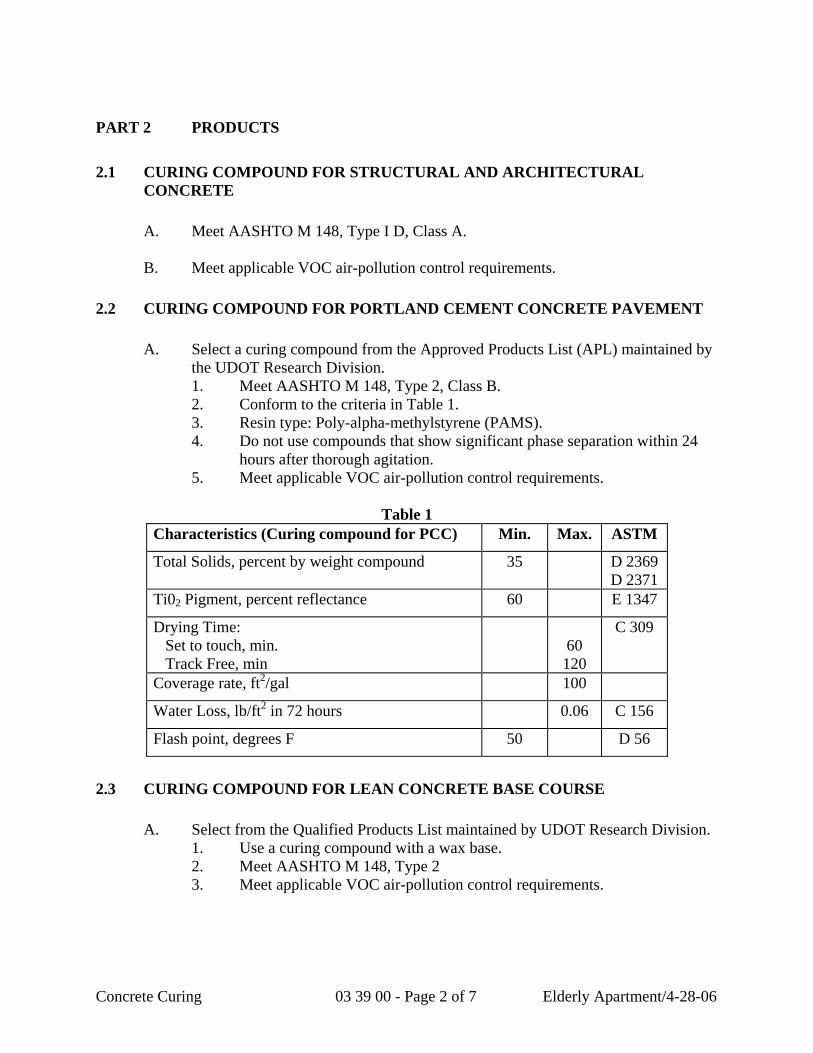
PART 2 PRODUCTS 2.1 CURING COMPOUND FOR STRUCTURAL AND ARCHITECTURAL
CONCRETE A. Meet AASHTO M 148, Type I D, Class A. B. Meet applicable VOC air-pollution control requirements. 2.2 CURING COMPOUND FOR PORTLAND CEMENT CONCRETE PAVEMENT
A. Select a curing compound from the Approved Products List (APL) maintained by the UDOT Research Division.
1. Meet AASHTO M 148, Type 2, Class B. 2. Conform to the criteria in Table 1. 3. Resin type: Poly-alpha-methylstyrene (PAMS).
4. Do not use compounds that show significant phase separation within 24 hours after thorough agitation.
5. Meet applicable VOC air-pollution control requirements.
Table 1 Characteristics (Curing compound for PCC) Min. Max. ASTM
Total Solids, percent by weight compound 35 D 2369 D 2371
Ti02 Pigment, percent reflectance 60 E 1347
Drying Time: Set to touch, min. Track Free, min
60 120
C 309
Coverage rate, ft2/gal 100
Water Loss, lb/ft2 in 72 hours 0.06 C 156
Flash point, degrees F 50 D 56
2.3 CURING COMPOUND FOR LEAN CONCRETE BASE COURSE A. Select from the Qualified Products List maintained by UDOT Research Division. 1. Use a curing compound with a wax base. 2. Meet AASHTO M 148, Type 2 3. Meet applicable VOC air-pollution control requirements.
Concrete Curing 03 39 00 - Page 2 of 7 Elderly Apartment/4-28-06
2.4 CURING COMPOUND FOR CONCRETE BARRIER
A. Select from the Accepted Products Listing maintained by UDOT Research Division.
1. Meet ASTM C 1315, Type 1, Class A. PART 3 EXECUTION 3.1 PREPARATION
A. Verify concrete surfaces are ready for curing. Correct conditions detrimental to timely and proper completion of the work. Do not proceed until unsatisfactory conditions are corrected.
B. Follow product manufacturer’s recommendations for preparing surfaces. C. For newly placed concrete using membrane-curing compound method:
1. Deliver the curing compound in a ready-mixed form with the pigment uniformly disbursed without diluting or altering the compound. If the compound is chilled and too viscous, warm it to a maximum of 100 degrees F.
2. Keep surfaces moist until the curing compound is applied. 3. Complete all patching or surface finishing before applying compound. D. For lean concrete base course curing: Do not dilute or alter the compound. 3.2 CURING STRUCTURES A. Bridge Decks, Approach Slabs, Curbs, and Parapets.
1. Apply membrane-curing compound at the manufacturer’s recommended rate so that no portion of the deck or approach slab is exposed to the atmosphere for more than 20 minutes after the tining or finishing operation.
2. Apply membrane-curing compound at a uniform rate of 100 ft2/gal. 3. Work bridge to follow immediately after the finishing machine to allow application of the curing compound while the concrete is still plastic.
Concrete Curing 03 39 00 - Page 3 of 7 Elderly Apartment/4-28-06
4. As soon as the concrete is sufficiently set to support the materials, cover bridge decks, approach slabs, curbs, and parapet walls with material that retains moisture and does not prevent evaporation, such as cotton or burlap mats. a. Restrain the cotton or burlap mats to prevent wind or other forces
from removing them. b. Do not damage the finish.
5. Keep concrete moist continuously for seven days after placement. Keep the entire surface damp, but do not wash away or erode the surface.
B. Other newly placed concrete: Use membrane-curing compound method. 1. Keep surfaces wet and moist until the curing compound is applied.
2. Complete all patching or surface finishing before applying compound. 3. Warm chilled compound that is too viscous to a maximum of
90 degrees F. 4. Apply curing compound immediately after finishing operations are
completed 5. Spray the entire surface of the concrete with a membrane curing
compound at a uniform rate of 100 ft2/gal. 6. Immediately re-spray any portion damaged before the seven-day curing
expires. 3.3 CURING CURB, GUTTER, FLATWORK, SIDEWALK, DRIVEWAY, AND
OTHER MISC CONCRETE ITEMS (CONCRETE SLOPE PROTECTION)
A. Refer to this Section, article 3.1, Preparation and article 3.2, Curing Structures, paragraph B, Other newly place concrete.
3.4 CURING PRE-STRESSED CONCRETE
A. Cure following this Section article 3.2, Curing Structures or article 3.10, Steam Curing, until concrete has reached a strength of 4,000 psi or as designated on the plans.
3.5 CURING PRE-CAST CONCRETE BARRIER A. Cure exposed surfaces immediately after finishing operations are completed. 1. Apply the curing compound at a rate of 100 ft2/gal.
B. After removing form, broom clean the surface of the barrier and apply two coats of curing compound.
1. Apply the first coat at a rate of 100 ft2/gal. 2. Allow the first coat to dry thoroughly before applying the second coat. 3. Apply the second coat at a rate of 200 ft2/gal.
Concrete Curing 03 39 00 - Page 4 of 7 Elderly Apartment/4-28-06
3.6 CURING CAST-IN-PLACE CONCRETE BARRIER A. Cure immediately after finishing operations are completed.
B. Apply two coats of curing compound as specified for Curing Pre-cast Concrete Barrier.
3.7 CURING PRE-CAST NOISE WALL
A. Cover surface of exposed aggregate noise wall panels with a moisture barrier or membrane immediately after initial finishing operations are completed.
B. Leave cover in place until final finishing operations (exposed aggregate) are
performed.
C. Remove cover, complete final finishing operations, and immediately apply curing compound.
1. Apply curing compound at a uniform rate of 100 ft2/gal. 2. After removing from forms, apply curing compound to all surfaces not
previously covered. D. Cure all other precast noise wall components.
1. Apply curing compound to all exposed surfaces immediately after finishing or form removal operations are completed.
2. Apply curing compound at a uniform rate of 100 ft2/gal. 3.8 CURING LEAN CONCRETE BASE COURSE A. After finishing operations are complete, apply curing compound. 1. Spray entire exposed area (top and sides) at a rate of 200 ft2/gal.
2. Use fully atomizing mechanical sprayers that have a wind-protective hood. 3. Hand spray on small areas and areas inaccessible to mechanical spraying
equipment. 4. Provide complete coverage with curing compound at edges, corners, sides,
and rough spots.
B. Damage to the film of curing compound occurring within 72 hours of application must be repaired immediately at no additional cost to Department.
Concrete Curing 03 39 00 - Page 5 of 7 Elderly Apartment/4-28-06
3.9 CURING PORTLAND CEMENT CONCRETE PAVEMENT
A. Pretest the liquid membrane curing compound using an infrared spectrometer to determine specification compliance.
B. Provide the Engineer with the test results before placing the concrete pavement.
C. Delay placing concrete pavement until an acceptable shipment of curing compound is received.
D. Warm viscous curing-sealing compound to a temperature not to exceed 100 degrees F if necessary.
E. Thoroughly mix the compound during use and uniformly disperse the pigment
throughout the vehicle. Stir continuously mechanically during application and do not dilute or alter in any manner.
F. Apply compound to the entire pavement surface and exposed edges immediately
after completing finishing operations: 1. Apply the curing compound in two approximately equal applications.
2. Apply the second application in the opposite longitudinal direction as the first at a combined application rate equal to 100 ft2/gal.
3. Allow at least 30 minutes between applications. 4. Small and irregular areas and areas inaccessible to mechanical spraying
equipment may be hand sprayed.
G. Stop paving operations if the application of the compound behind the paving machine is delayed until the problem is resolved. 1. Keep the pavement moist with water until the compound application
process is resumed. 2. Apply the water in a fog-mist spray without damaging the pavement
surface texture.
H. Immediately repair any damage to the compound film occurring until seven days after the initial application at no additional cost to Department.
3.10 STEAM CURING A. Steam curing.
1. Provide a complete steam curing system approved by the Engineer, including 24 hour temperature control and monitoring devices, and a suitable enclosure to contain live steam and minimize moisture and heat losses.
2. Do not apply steam until the concrete has set. Wait four to six hours if retarders are used. If no retarders are used, wait two to four hours.
3. Maintain 100 percent relative humidity in the steam curing enclosure.
Concrete Curing 03 39 00 - Page 6 of 7 Elderly Apartment/4-28-06
4. Do not apply steam directly on the concrete. 5. When applying steam, increase the ambient air temperature at a rate not to
exceed a 40 degrees F per hour until a temperature range of 140 degrees to 160 degrees F is reached.
6. Maintain the temperature range until the concrete has reached the specified strength.
7. When discontinuing the steam, decrease the ambient air temperature at a rate not to exceed a 40 degrees F per hour until reaching a temperature of not more than 20 degrees F above the air temperature to which the concrete will be exposed.
END OF SECTION
Concrete Curing 03 39 00 - Page 7 of 7 Elderly Apartment/4-28-06

Project Name / 92-07 / 10-6-92 04 05 13 - 1 Masonry Mortar
SECTION 04 05 13
MASONRY MORTAR
PART 1 GENERAL
1.01 SECTION INCLUDES
A. Mortar for unit masonry and stone veneer.
1.02 RELATED SECTIONS
A. Section 04 20 00 – Unit Masonry: Mortar for concrete unit masonry.
B. Section 04 43 00 – Stone Veneer: Mortar for natural stone veneer.
1.03 REFERENCES
A. ASTM C150 – Portland Cement.
B. ASTM C144 – Aggregate for Masonry Mortar.
C. ASTM C207 – Hydrated Lime for Masonry Mortar
D. ASTM C270 – Mortar for Unit Masonry
E. International Masonry Industry All-Weather Council (IMIAC) - Recommended Practices and Guide Specifications for Cold Weather Masonry Construction.
1.04 DELIVERY, STORAGE, AND HANDLING
A. Deliver products to site under provisions of Section 01 65 00.
B. Store and protect products under provisions of Section 01 66 00.
C. Protect cement from moisture and humidity
1.05 ENVIRONMENTAL REQUIREMENTS
A. Cold Weather Requirements: IMIAC requirements.
B. Maintain materials and surrounding air temperature to minimum 10 degrees C (40 degrees F) prior to, during, and 48 hours after completion of masonry work.
PART 2 PRODUCTS
2.01 MATERIALS
Masonry Mortar 04 05 13 - 2 Project Name / 92-07 / 10-6-92
A. Portland Cement: ASTM C150, Normal – Type I, white color for facebrick and grey color for common brick
B. Mortar aggregate: ASTM C144, standard masonry type; clean dry; protected from dampness, freezing, or foreign matter.
C. Hydrated Lime: ASTM C207, Type S.
D. Water: Clean and potable.
E. Mortar Color: Mineral oxide pigment; chocolate brown color; “Great Stuff” manufactured by Acme Manufacturing Co. Ltd.
2.02 MIXES
A. Mortar for Load Bearing Walls and Partitions: ASTM C270, Type S, using proportion method.
B. Mortar for Non-Load Bearing Walls and Partitions: ASTM C270, Type N, using proportion method.
2.03 MORTAR MIXING
A. Thoroughly mix mortar ingredients in quantities needed for immediate use in accordance with ASTM C270.
B. Add mortar color in accordance with manufacturer’s instructions. Provide uniformity of mix and coloration.
C. Do not use anti-freeze compounds to lower the freezing point of mortar.
PART 3 EXECUTION
3.01 INSTALLATION
A. Install mortar in conjunction with Sections 04 20 00 and 04 43 00.
3.02 FIELD QUALITY CONTROL
A. Field testing will be performed under provisions of Section 01 45 00.
END OF SECTION
SECTION 04 05 19
ADJUSTABLE MASONRY ANCHORS
PART 1 GENERAL
1.1 SECTION INCLUDES
A. Masonry veneer anchors and ties.
B. Stone veneer anchors and ties.
1.2 RELATED SECTIONS
A. Section 04810 - Unit Masonry Assemblies.
B. Section 04851 - Cut Stone Veneer.
C. Section 04852 - Stone Masonry Veneer.
D. Section 04853 - Cut Stone Assemblies.
1.3 REFERENCES
A. ACI 530.1/ASCE 6/TMS 602 - Specification for Masonry Structures; 1995.
B. ASTM A 153/A 153M - Standard Specification for Zinc Coating (Hot-Dip) on Iron and Steel Hardware; 1998.
C. ASTM A 167 - Standard Specification for Stainless and Heat-Resisting Chromium-Nickel Steel Plate, Sheet, and Strip; 1996.
D. ASTM A 240/A 240M - Standard Specification for Heat-Resisting Chromium and Chromium-Nickel Stainless Steel Plate, Sheet, and Strip for Pressure Vessels; 1998b.
E. ASTM A 276 - Standard Specification for Stainless Steel Bars and Shapes; 1998b.
F. ASTM A 479/A 479M - Standard Specification for Stainless and Heat-Resisting Steel Bars and Shapes for Use in Boilers and Other Pressure Vessels; 1997a.
G. ASTM A 580/A 580M - Standard Specification for Stainless Steel Wire; 1998.
H. ASTM A 641/A 641 M - Standard Specification for Zinc-Coated (Galvanized) Carbon Steel Wire; 1998.
I. ASTM A 653/A 653M - Standard Specification for Steel Sheet, Zinc-Coated (Galvanized) or Zinc-Iron Alloy-Coated (Galvannealed) by the Hot-Dip Process; 1998.
Elderly Apartment / 11-21-06 04 05 19 – 1 Adjustable Masonry Anchor
J. ASTM B 633 - Standard Specification for Electrodeposited Coatings of Zinc on Iron and Steel; 1985 (Reapproved 1994).
1.4 DELIVERY, STORAGE, AND HANDLING
A. Store products in manufacturer's unopened packaging until ready for installation.
PART 2 PRODUCTS
2.1 MANUFACTURERS
A. Acceptable Manufacturer: Heckmann Building Products Inc., 1501 N. 31st Avenue, Melrose Park, IL 60160-2911. ASD. Tel: (708) 865-2403. Tel: (800) 621-4140. Fax: (708) 865-2640.
B. Substitutions: Not permitted.
2.2 MATERIAL
A. Material for Anchors and Ties in Exterior Walls:
1. Stainless steel.
2. Hot-dip galvanized.
3. Structural Plates, Angles, and Bars: Hot-dip galvanized.
B. Material for Anchors and Ties Exposed to Air in Exterior Walls:
1. Stainless steel.
2. Hot-dip galvanized.
C. Material for Ties in Interior Wall Completely Embedded in Mortar Joints:
1. Mill galvanized.
2.3 MASONRY VENEER ANCHORS AND TIES
A. Adjustable Two Piece Masonry Veneer Ties: Requires minimum 1-1/2 inches (38 mm) embedment in brick mortar or a minimum of one half of the thickness of a block wall with at least 5/8 inches (15.9 mm) mortar cover to the outside face.
1. Pos-I-Tie Anchors and Pos-I-Tie Wire Tie.
a. Pos-I-Tie Barrel Screws:
1) Substrate and Screw Type:
a) Steel Studs: Self Drilling Screws.
Adjustable Masonry Anchor 04 05 19 – 2 Elderly Apartment / 11-21-06
b) Concrete, CMU, Brick or Wood: Tapcon screws.
c) Structural Steel: Dril-It screws.
2) Barrel Length:
a) 5/8 inch (15.9 mm).
b) 1 inch (25.4 mm).
c) 1-1/2 inch (39 mm).
d) 2 inch (51 mm).
e) 2-1/2 inch (63.5 mm).
f) 3 inch (76 mm).
g) 3-1/2 inch (89 mm).
b. Pos-I-Tie Wire Ties:
1) Triangle Wire Tie
2) Single Wire Tie
3) Seismic Triangle Tie
c. Wire Tie Length:
1) 3 inch (76 mm)
2) 3-1/2 inch (89 mm)
3) 4 inch (101.6 mm)
4) 5 inch (127 mm)
2. Strap Anchors with Triangle Ties
a. Strap Anchor for attachment to backup using triangle ties
1) Weld-On Anchor Rod No. 315:
a) 1/4 inch (6.3 mm) diameter by 5 inches (127 mm) long.
b) 1/4 inch (6.3 mm) diameter by 9 inches (228.6 mm) long.
2) Weld-On Anchor Strap No. 315-B:
Adjustable Masonry Anchor 04 05 19 – 3 Elderly Apartment / 11-21-06
a) 12 Gauge (2.7 mm) by 3/4 inches (19 mm) by 9 inches (228.6 mm).
b) 12 Gauge (2.7 mm) by 7/8 inch (22.2 mm) x 6-1/2 inches (165 mm).
3) Screw-On Anchor Strap No. 315-C:
a) 12 Gauge (2.7 mm) by 3/4 inches (19 mm) by 9 inches (228.6 mm)
b) 12 Gauge (2.7 mm) by 7/8 inches (22.2 mm) by 6-1/2 inches (165 mm)
4) Screw-On Anchor Plate No. 315-D: 1-1/4 inches wide by 6 inches long:
a) 12 Gauge (2.7 mm).
b) 14 Gauge.
c) 16 Gauge.
b. Triangle Tie: No. 316 Triangle Tie 3/16 inch diameter (4.76 mm):
1) 3 inch (76 mm) long.
2) 3-1/2 inch (89 mm) long.
3) 4 inch (101.6 mm) long.
4) 5 inch (127 mm) long.
5) 7 inch (178 mm) long.
6) 9 inch (228.6 mm) long.
7) 11 inch (279.4 mm) long.
3. Strap Anchors with Pintle Ties:
a. Strap Anchor for attachment to backup with Pintle tie
1) Wire Veneer Anchor System No. 213: 14 Gauge (1.9 mm) backplate for use with following insulation thickness:
a) No Insulation.
b) 1 inch (25.5 mm) insulation.
c) 1-1/2 inches (38 mm) insulation.
Adjustable Masonry Anchor 04 05 19 – 4 Elderly Apartment / 11-21-06
d) 2 inches (51 mm) insulation.
e) 3 inches (76 mm) insulation.
b. Double Pintle Wire Tie No. 282: 3/16 inch diameter.
1) 3-1/4 inch (82.5 mm) long.
2) 4-1/4 inch (108 mm) long.
3) 5-1/4 inch (133.3 mm) long.
c. Double eye rod anchor: No. 262.
1) Diameter: 3/16 inch (4.76 mm).
2) Length:
a) 2-3/4 inch (70 mm).
b) 4-3/4 inch (120 mm)
d. Double anchor tie (pintle): No. 263
1) Diameter: 3/16 inch (4.76 mm).
2) Length:
a) 3 inch (76 mm).
b) 4 inch (102 mm)
c) 5 inch (127 mm).
2.4 STONE VENEER ANCHORS AND TIES
A. For Anchoring Into Edge of Dimension Stone Panels:
1. Dovetail Stone Pin Anchor No. 118: (Use with concrete backup containing No. 100 Dovetail Anchor Slot)
a. Metal Thickness:
1) 3/16 inch (4.7 mm) - Standard
2) 1/8 inch (3.1 mm) - Special.
3) 12 gauge (2.7 mm) - Special.
b. Width: 1 inch (25.5 mm).
Adjustable Masonry Anchor 04 05 19 – 5 Elderly Apartment / 11-21-06
c. Length as indicated on the Drawings.
d. Length: _______ inches.
e. Pin:
1) Welded.
2) Loose.
3) Diameter:
a) 1/4 inch (6.35 mm).
b) 3/8 inch (9.52 mm).
c) 1/2 inch (12.5 mm).
d) 5/8 inch (15.87 mm).
4) Length: 3 inches (76 mm).
2. Channel Slot Pin Anchor No. 137: (Use with backup system with Channel Slots)
a. Metal Thickness:
1) 3/16 inch (4.7 mm) - Standard
2) 1/8 inch (3.1 mm) - Special.
3) 12 gauge (2.7 mm) - Special.
b. Width: 1-1/4 inch (31.71 mm).
c. Length as indicated on the Drawings.
d. Length: _______ inches.
e. Pin:
1) Welded.
2) Loose.
3) Diameter:
a) 1/4 inch (6.35 mm).
b) 3/8 inch (9.52 mm).
Adjustable Masonry Anchor 04 05 19 – 6 Elderly Apartment / 11-21-06
c) 1/2 inch (12.5 mm).
d) 5/8 inch (15.87 mm).
4) Length: 3 inches (76 mm).
B. For Anchoring Into Edge of Dimension Stone Panels: Use slot type;
1. Dovetail Bent Stone Anchor No.115 (For use with concrete backup with No. 100 Dovetail Anchor Slot)
a. Metal Thickness:
1) 3/16 inch (4.7 mm) - Standard
2) 1/8 inch (3.1 mm) - Special.
b. Width: 1 inch (25.5 mm).
c. Length as indicated on the Drawings.
d. Length: _______ inches.
e. Bend: 3/4 inch.
2. Dovetail Split-Bend Anchor No.117: Anchor (For use with concrete backup with No. 100 Dovetail Anchor Slot)
a. Metal Thickness:
1) 3/16 inch (4.7 mm) - Standard
b. Width: 1-1/4 inch (31.75 mm).
c. Length as indicated on the Drawings.
d. Length: _______ inches.
e. Split Bend: 3/4 inch.
3. Channel Slot Bent Anchor No.135: (Use with backup system with Channel Slots)
a. Metal Thickness:
1) 1/4 inch (6.35 mm).
2) 3/16 inch (4.7 mm).
3) 1/8 inch (3.17 mm).
Adjustable Masonry Anchor 04 05 19 – 7 Elderly Apartment / 11-21-06
4) 11 gauge (3.0 mm).
5) 12 gauge (2.7 mm).
6) 16 gauge (1.5 mm).
b. Width as indicated on the Drawings.
c. Width: _______ inches.
d. Length as indicated on the Drawings.
e. Length: _______ inches.
f. Bend: 3/4 inch (19 mm).
2.5 DOVETAIL SLOT ANCHORS AND TIES
A. Standard Dovetail Slots and Ties:
1. Dovetail Slots: No.100 Standard Dovetail Anchor Slot.
a. Size: 1 inch (25 mm) wide by 1 inch (25 mm) deep by 5/8 inch (16 mm) throat.
b. Thickness:
1) 20 Gauge (0.9 mm).
2) 22 Gauge (0.76 mm).
3) 24 Gauge (0.61 mm).
4) 26 Gauge (0.45).
2. For Use With Dovetail Slots: No.106; corrugated straps of length to suit application:
a. Gauge:
1) 12 gauge.
2) 16 gauge.
b. Width: 1 inch (25.5 mm).
c. Length from face of Concrete:
1) Length as indicated on the Drawings.
Adjustable Masonry Anchor 04 05 19 – 8 Elderly Apartment / 11-21-06
2) Length: _______ inches.
3. For Use With Dovetail Slots: No. 104; corrugated straps of length to suit application:
a. Gauge:
1) 16 gauge (1.5 mm) - Standard.
b. Width: 1-1/2 inch (38 mm).
c. Length from face of Concrete:
1) Length as indicated on the Drawings.
2) Length: _______ inches.
4. For Use With Dovetail Slots: No.115; bent straps:
a. Thickness:
1) 3/16 inch (4.7 mm).
2) 1/8 inch (3.1 mm).
b. Width: 1 inch (25.5 mm).
c. Length from face of Concrete:
1) Length as indicated on the Drawings.
2) Length: _______ inches.
d. Bend: 3/4 inch (19 mm).
5. Ties:
a. Dovetail Triangle Tie No. 103: 12 Gauge (2.7 mm) clip factory assembled to a No. 316 Triangle tie 3/16 inch (4.76 mm) diameter by tie length of:
1) 3 inch (76 mm).
2) 4 inch (102 mm).
3) 5 inch (127 mm).
4) 9 inch (229 mm).
Adjustable Masonry Anchor 04 05 19 – 9 Elderly Apartment / 11-21-06
5) 11 inch (279 mm).
2.6 MASONRY WALL STABILIZING ANCHORS
A. For use in anchoring top of wall to structure while allowing vertical deflection.
1. Type: No. 419; 12 Gauge (2.6 mm) plate with 3/8 inch (10 mm) diameter pin; plate anchored to structure overhead, pin sliding in plastic tube embedded in mortar at top of wall.Specify Type of Steel, Length of pin.
2. Type: No. 420; 12 Gauge (2.6 mm) channel cap; attached to structure overhead. Specify Gauge, Length, Width, bend lengths, type of steel.
3. Type: 138 Channel Slot Flat Anchor for structural beam with Welded Channel Slot:
a. Metal Thickness:
1) 1/8 inch (3.1 mm).
2) 11 gauge (3.0 mm).
3) 12 gauge (2.7 mm).
4) 14 gauge (1.9 mm).
5) 16 gauge (1.5 mm).
b. Width: 1-1/4 inches (32 mm) wide.
c. Length:
1) As indicated on the Drawings.
2) Define ____________.
4. Type: 138-R Channel Slot Threaded Rod Anchor: Threaded rod welded 1 inch (25.5 mm) onto a 12 gauge (2.7 mm) dovetail clip 1 inch with end extending 1 inch beyond the face of the dove tail slot.
a. Rod diameter:
1) 1/4 inch (6.35 mm).
2) 3/8 inch (9.52 mm).
3) 1/2 inch (12.5 mm).
4) 5/8 inch (15.87 mm).
b. Length of rod:
Adjustable Masonry Anchor 04 05 19 – 10 Elderly Apartment / 11-21-06
1) As indicated on the Drawings.
2) Define ____________.
c. Plastic Tube No. 421 over pin.
5. Type: No.121; threaded rod used with a No. 100 Dovetail Slot built into top of slab.
a. Dovetail anchor 12 gauge (2.5 mm) by 1 inch (25.5 mm) wide with length as indicated on the Drawings.
b. Diameter of threaded rod: 3/8 inch (9.52 mm).
c. Length of flat part from face of concrete: As indicated on the Drawings.
d. Length of threaded rod beyond flat part: As indicated on the Drawings.
e. Plastic Tube No. 421 over pin.
6. Type: No.109 Dovetail Flat Anchor used with a No. 100 Dovetail Slot built into top of slab.
a. Dovetail anchor 12 gauge (2.5 mm) by 1 inch (26 mm) wide with length as indicated on the Drawings.
b. Plastic Tube No. 421 over anchor.
2.7 ACCESSORIES
A. Remedial Ties: No.391; Spiro Remedial Tie screw-in anchors.
1. Length:
a. As indicated on the Drawings.
b. Define ____________.
B. Ledge Angle, Shelf Angle, and Lintel Angles:
1. Anchors in Concrete:
a. No. 425; malleable iron wedge inserts, cast in place with reinforcing bar anchor.
1) Size:
a) 3/4 inch (19 mm) regular
b) 3/4 inch (19 mm) long
Adjustable Masonry Anchor 04 05 19 – 11 Elderly Apartment / 11-21-06
b. No. 427 askew head bolts.
1) Length:
a) As indicated on the Drawings.
b) Define _________
2. Anchors in Concrete: Cast-in-place studded anchor plates as detailed.
• 3. Anchors to Steel: No. 700 series; field welded.
C. Control Joint Fillers: No. 352; flexible rubber seals fitting in sash block reveals.
1. Length:
a. As indicated on the Drawings.
• b. Define ____________.
D. Control Joint Anchors: Tie masonry together while allowing movement.
1. Type: No.350 Heavy Duty Control Joint Anchor.
2. Type: No.351 Corrugated Control Joint Anchor.
1. 3. Type: No. 353 Debonded Shear Anchor.
PART 3 EXECUTION
3.1 PREPARATION
A. Clean materials thoroughly prior to installation.
3.2 INSTALLATION
A. Install in masonry anchors and accessories in accordance with manufacturer's printed instructions.
B. Concrete unit masonry installation is specified in Section 04810.
C. Brick masonry installation is specified in Section 04810
D. Stone masonry installation is specified in Section 04850
3.3 PROTECTION
A. Protect installed products until completion of project.
B. Touch-up, repair or replace damaged products before Substantial Completion.
Adjustable Masonry Anchor 04 05 19 – 12 Elderly Apartment / 11-21-06

END OF SECTION
Adjustable Masonry Anchor 04 05 19 – 13 Elderly Apartment / 11-21-06
SECTION 04 05 23
MASONRY ACCESSORIES GENERAL
1.1 SECTION INCLUDES
A. Masonry cavity wall drainage systems.
B. Masonry wall weep vents.
1.2 RELATED SECTIONS
A. Section 04 05 00 - Common Work Results for Masonry.
B. Section 04 20 00 - Units Masonry.
C. Section 04 40 00 - Stone Assemblies.
D. Section 04 70 00 - Manufactured Masonry.
E. Section 07 10 00 - Water Repellents: Masonry wall coatings.
F. Section 07 20 00 - Thermal Protection: Building Insulation.
G. Section 07 60 00 - Flashing and Sheet Metal: Metal counter flashing installation and coordination requirements.
1.3 SUBMITTALS
A. Submit under provisions of Section 01 30 00.
B. [ Product Data ]: Manufacturer's data sheets on each product to be used, including: 1. Preparation instructions and recommendations. 2. Storage and handling requirements and recommendations.
C. Selection Samples: For Mortar Net Weep Vents specified, two complete sets of product representing manufacturer's full range of available colors and patterns.
D. Verification Samples: For each Mortar Net Weep Vents specified, two samples, minimum size 6 inches (150 mm) square, representing actual product, color, and configuration.
1.4 QUALITY ASSURANCE
A. Installer Qualifications: Minimum 2 years experience with similar masonry installations.
Elderly Apartment 4/26/06 04 05 23 – 1 Masonry Accessories
1.5 DELIVERY, STORAGE, AND HANDLING
A. Store products in manufacturer's unopened packaging until ready for installation.
B. Protect products from exposure to direct sunlight.
PART 2 PRODUCTS
2.1 MANUFACTURERS
A. Acceptable Manufacturer: Mortar Net USA Limited, which is located at: 541 S. Lake St. ; Gary, IN 46403; Toll Free Tel: 800-664-6638; Fax: 219-939-3877; Email: [email protected]; Web: www.mortarnet.com
B. Substitutions: Not permitted.
C. Requests for substitutions will be considered in accordance with provisions of Section 01 60 00.
2.2 MATERIALS
A. Brick Cavity Wall Drainage System: Mortar Net as manufactured by Mortar Net USA, Ltd., 90 percent open weave mesh, dovetail configuration with continuous bottom strip. 1. Material and Thickness: Nylon; 0.4 inches (10 mm). 2. Material and Thickness: High-density polyethylene (HDPE); 1 inch
(25 mm). 3. Material and Thickness: Recycled polyester; 2 inches (51 mm) thick.
B. Brick Cavity Wall Drainage System: House Net as manufactured by Mortar Net USA, Ltd., recycled polyester; 90 percent open weave mesh, dovetail configuration with continuous bottom strip. 1. Thickness: 0.4 inches (10 mm). 2. Thickness: 1 inch (25 mm). 3. Thickness: 2 inches (51 mm).
C. Brick Cavity Wall Weep Vents: Mortar Net Weep Vents as manufactured by Mortar Net, USA Ltd. UV-resistant recycled polyester; 90 percent open weave mesh, rectangular shape. 1. Color: Match mortar color with selection from manufacturer's standard
colors. 2. Color: White. 3. Color: Brown. 4. Color: Tan. 5. Color: Gray. 6. Color: Red. 7. Color: Almond.
D. Concrete Masonry Unit Cavity Wall Drainage System: Blok-Flash as
Elderly Apartment 4/26/06 04 05 23 – 2 Masonry Accessories
manufactured by Mortar Net USA, Ltd., high-density polyethylene, molded flashing pan with integral weep spout. 1. Width: Model US-8; 5-5/8 inches (143 mm). 2. Width: Model US-10; 7-5/8 inches (194 mm). 3. Width: Model US-12; 9-5/8 inches (245 mm).
E. Concrete Masonry Unit Cavity Wall Drainage System: BlockNet as manufactured by Mortar Net USA, Ltd. Stainless steel drainage strip with integrated drip edge, horizontal mesh, rear water dam, and 90 percent open weave polyester vertical mesh.
PART 3 EXECUTION
3.1 EXAMINATION
A. Do not begin installation until substrates have been properly prepared.
B. If substrate preparation is the responsibility of another installer, notify Architect of unsatisfactory preparation before proceeding.
3.2 INSTALLATION
A. Install in accordance with manufacturer's instructions.
B. Brick Cavity Wall Drainage System: Mortar Net as manufactured by Mortar Net USA, Ltd. Install in strict accordance with manufacturer's instructions and as follows: 1. Verify installation of flashing and completion of first two courses of
masonry. 2. Extend flashing from the bottom of the Mortar Net to at least 6 inches
(152 mm) above the top of the House Net to prevent mortar bridging between the outer wythe and inner wall.
3. Remove mortar droppings and debris from flashing and weep holes. 4. Install in cavity directly on flashing, with dovetail profile facing
upward. Butt ends together. Compress slightly if necessary.
C. Brick Cavity Wall Drainage System: House Net as manufactured by Mortar Net USA, Ltd. Install in strict accordance with manufacturer's instructions and as follows: 1. Verify installation of flashing and completion of first two courses of
masonry. 2. Extend flashing from the bottom of the House Net to at least 6 inches
(152 mm) above the top of the Mortar Net to prevent mortar bridging between the outer Wythe and inner wall.
3. Remove mortar droppings and debris from flashing and weep holes. 4. Install in cavity directly on flashing, with dovetail profile facing
upward. Butt ends together. Compress slightly if necessary.
D. Weep Vents: Mortar Net Weep Vents as manufactured by Mortar Net USA,
Elderly Apartment 4/26/06 04 05 23 – 3 Masonry Accessories
Ltd.: Install in strict accordance with manufacturer's instructions and as follows: 1. Clean flashing and weep holes free of mortar droppings and debris. 2. Align exterior face of insert with exterior plane of mortar. 3. For head joints taller than height of mesh insert, coordinate installation
of mortar above insert to prevent clogging. 4. Fill head joint with 1/8 inch (3 mm) recess from face of masonry.
E. Concrete Masonry Unit Cavity Wall Drainage System: Blok-Flash as manufactured by Mortar Net USA, Ltd. Install in strict accordance with manufacturer's instructions and as follows: 1. Install on top of foundation or under first concrete masonry unit course
closest to foundation, not less than 4 inches (102 mm) above finish grade.
2. Install with weep spouts slightly beyond the edge of foundation or concrete masonry unit course.
3. Install with standard mortar spreading techniques with mortar lapped, first over the inner and second over the outer flanges of the Blok-Flash units.
4. Install 2 to 3 inches (51 to 76 mm) of pea stone in concrete masonry unit core cavity above the Blok-Flash locations to reduce clogging from mortar and grout droppings.
5. Remove obstructions from weep spouts.
F. Concrete Masonry Unit Cavity Wall Drainage System: BlockNet as manufactured by Mortar Net USA, Ltd. Install in strict accordance with manufacturer's instructions and as follows: 1. Install mesh-side up, with weep spout in alignment with edge of
foundation or first concrete masonry unit course closest to foundation, but not above interior floor.
2. Caulk unmeshed end section of strip and align and butt edges of adjacent strip.
3. Install one vertical 7 inch by 7 inch (178 by 178 mm) mesh unit in the core of each concrete masonry unit in first course.
4. Remove obstructions from weep spouts.
3.3 PROTECTION
A. Protect installed products from damage until completion of project.
B. Repair or replace damaged products before covering with construction.
END OF SECTION
Elderly Apartment 4/26/06 04 05 23 – 4 Masonry Accessories
SECTION 04 09 0
MORTAR NET GENERAL
1.1 SECTION INCLUDES
A. Masonry cavity wall drainage systems.
B. Masonry wall weep vents.
1.2 RELATED SECTIONS
A. Section 04050 - Basic Masonry Materials and Methods: Additional masonry materials.
B. Section 04200 - Masonry Units: Masonry installation and coordination requirements.
C. Section 04400 - Stone: Stone installation and coordination requirements.
D. Section 04800 - Masonry Assemblies: Additional masonry assembly requirements.
E. Section 07190 - Water Repellents: Masonry wall coatings.
F. Section 07200 - Thermal Protection: Building Insulation.
G. Section 07600 - Flashing and Sheet Metal: Metal counter flashing installation and coordination requirements.
1.3 SUBMITTALS
A. Submit under provisions of Section 01300.
B. [ Product Data ]: Manufacturer's data sheets on each product to be used, including: 1. Preparation instructions and recommendations. 2. Storage and handling requirements and recommendations.
C. Selection Samples: For Mortar Net Weep Vents specified, two complete sets of product representing manufacturer's full range of available colors and patterns.
D. Verification Samples: For each Mortar Net Weep Vents specified, two samples, minimum size 6 inches (150 mm) square, representing actual product, color, and configuration.
1.4 QUALITY ASSURANCE
Elderly Apartment 11/18/06 04 09 0-1 Mortar Net
A. Installer Qualifications: Minimum 2 years experience with similar masonry installations.
1.5 DELIVERY, STORAGE, AND HANDLING
A. Store products in manufacturer's unopened packaging until ready for installation.
B. Protect products from exposure to direct sunlight.
PART 2 PRODUCTS
2.1 MANUFACTURERS
A. Acceptable Manufacturer: Mortar Net USA Limited, which is located at: 541 S. Lake St. ; Gary, IN 46403; Toll Free Tel: 800-664-6638; Fax: 219-939-3877; Email: [email protected]; Web: www.mortarnet.com
B. Substitutions: Not permitted.
C. Requests for substitutions will be considered in accordance with provisions of Section 01600.
2.2 MATERIALS
A. Brick Cavity Wall Drainage System: Mortar Net as manufactured by Mortar Net USA, Ltd., 90 percent open weave mesh, dovetail configuration with continuous bottom strip. 1. Material and Thickness: Nylon; 0.4 inches (10 mm). 2. Material and Thickness: High-density polyethylene (HDPE); 1 inch
(25 mm). 3. Material and Thickness: Recycled polyester; 2 inches (51 mm) thick.
B. Brick Cavity Wall Drainage System: House Net as manufactured by Mortar Net USA, Ltd ., recycled polyester; 90 percent open weave mesh, dovetail configuration with continuous bottom strip. 1. Thickness: 0.4 inches (10 mm). 2. Thickness: 1 inch (25 mm). 3. Thickness: 2 inches (51 mm).
C. Brick Cavity Wall Weep Vents: Mortar Net Weep Vents as manufactured by Mortar Net, USA Ltd. UV-resistant recycled polyester; 90 percent open weave mesh, rectangular shape. 1. Color: Match mortar color with selection from manufacturer's standard
colors. 2. Color: White. 3. Color: Brown. 4. Color: Tan. 5. Color: Gray. 6. Color: Red.
Elderly Apartment 11/18/06 04 09 0-2 Mortar Net
7. Color: Almond.
D. Concrete Masonry Unit Cavity Wall Drainage System: Blok-Flash as manufactured by Mortar Net USA, Ltd., high-density polyethylene, molded flashing pan with integral weep spout. 1. Width: Model US-8; 5-5/8 inches (143 mm). 2. Width: Model US-10; 7-5/8 inches (194 mm). 3. Width: Model US-12; 9-5/8 inches (245 mm).
E. Concrete Masonry Unit Cavity Wall Drainage System: BlockNet as manufactured by Mortar Net USA, Ltd. Stainless steel drainage strip with integrated drip edge, horizontal mesh, rear water dam, and 90 percent open weave polyester vertical mesh.
PART 3 EXECUTION
3.1 EXAMINATION
A. Do not begin installation until substrates have been properly prepared.
B. If substrate preparation is the responsibility of another installer, notify Architect of unsatisfactory preparation before proceeding.
3.2 INSTALLATION
A. Install in accordance with manufacturer's instructions.
B. Brick Cavity Wall Drainage System: Mortar Net as manufactured by Mortar Net USA, Ltd. Install in strict accordance with manufacturer's instructions and as follows: 1. Verify installation of flashing and completion of first two courses of
masonry. 2. Extend flashing from the bottom of the Mortar Net to at least 6 inches
(152 mm) above the top of the House Net to prevent mortar bridging between the outer wythe and inner wall.
3. Remove mortar droppings and debris from flashing and weep holes. 4. Install in cavity directly on flashing, with dovetail profile facing
upward. Butt ends together. Compress slightly if necessary.
C. Brick Cavity Wall Drainage System: House Net as manufactured by Mortar Net USA, Ltd. Install in strict accordance with manufacturer's instructions and as follows: 1. Verify installation of flashing and completion of first two courses of
masonry. 2. Extend flashing from the bottom of the House Net to at least 6 inches
(152 mm) above the top of the Mortar Net to prevent mortar bridging between the outer wythe and inner wall.
3. Remove mortar droppings and debris from flashing and weep holes. 4. Install in cavity directly on flashing, with dovetail profile facing
Elderly Apartment 11/18/06 04 09 0-3 Mortar Net
upward. Butt ends together. Compress slightly if necessary.
D. Weep Vents: Mortar Net Weep Vents as manufactured by Mortar Net USA, Ltd.: Install in strict accordance with manufacturer's instructions and as follows: 1. Clean flashing and weep holes free of mortar droppings and debris. 2. Align exterior face of insert with exterior plane of mortar. 3. For head joints taller than height of mesh insert, coordinate installation
of mortar above insert to prevent clogging. 4. Fill head joint with 1/8 inch (3 mm) recess from face of masonry.
E. Concrete Masonry Unit Cavity Wall Drainage System: Blok-Flash as manufactured by Mortar Net USA, Ltd. Install in strict accordance with manufacturer's instructions and as follows: 1. Install on top of foundation or under first concrete masonry unit course
closest to foundation, not less than 4 inches (102 mm) above finish grade.
2. Install with weep spouts slightly beyond the edge of foundation or concrete masonry unit course.
3. Install with standard mortar spreading techniques with mortar lapped, first over the inner and second over the outer flanges of the Blok-Flash units.
4. Install 2 to 3 inches (51 to 76 mm) of pea stone in concrete masonry unit core cavity above the Blok-Flash locations to reduce clogging from mortar and grout droppings.
5. Remove obstructions from weep spouts.
F. Concrete Masonry Unit Cavity Wall Drainage System: BlockNet as manufactured by Mortar Net USA, Ltd. Install in strict accordance with manufacturer's instructions and as follows: 1. Install mesh-side up, with weep spout in alignment with edge of
foundation or first concrete masonry unit course closest to foundation, but not above interior floor.
2. Caulk unmeshed end section of strip and align and butt edges of adjacent strip.
3. Install one vertical 7 inch by 7 inch (178 by 178 mm) mesh unit in the core of each concrete masonry unit in first course.
4. Remove obstructions from weep spouts.
3.3 PROTECTION
A. Protect installed products from damage until completion of project.
B. Repair or replace damaged products before covering with construction.
END OF SECTION
Elderly Apartment 11/18/06 04 09 0-4 Mortar Net
Elderly Apartment / 11-21-0604 21 13 - 1 Brick Masonry
SECTION 04 21 13
BRICK MASONRY PART 1 GENERAL 1.01 RELATED WORK SPECIFIED ELSEWHERE A. Mortar: Section 04061. B. Concrete Unit Masonry: Section 04220. C. Masonry Restoration: Section 04911. D. Built-In Flashings: Section 07620. 1.02 SUBMITTALS A. Samples: 1. Facing Brick: 25, each type, showing full range of color and texture. 2. Building Brick (Exposed Exterior): 12, showing full range of shading. 3. Building Brick (Exposed Interior): 12, showing full range of shading. 4. Building Brick (Back-up): 6. 5. Accessories: Each item specified, full size or 24 inch long sections as applicable. B. Quality Control Submittals: 1. Test Reports: At the written request of the Director, submit certified test reports for
each type of brick specified as follows: a. Compressive strength. b. Twenty-four hour cold water absorption. c. Five hour boiling water absorption. d. Saturation coefficient. e. Initial rate of absorption (suction). 1.03 QUALITY ASSURANCE A. Field Examples: 1. Prior to installation of brick masonry, construct a sample brick masonry wall panel at
the Site. 2. Build panel 4 feet long by 3 feet high by full wall thickness, with materials, bond,
joints, accessories, and back-up masonry required for the Work. 3. Construct a separate panel for each kind of exposed brick. 4. Do not start brick masonry until a sample panel has been approved by the Director's
Representative. 5. Approved panel will be the standard of workmanship required for all masonry built
of the same materials. Failure to maintain this standard will be cause for rejection of the masonry.
6. Maintain approved panel intact until all brick masonry has been installed and approved; then remove panel from the Site.
1.04 DELIVERY, STORAGE AND HANDLING
Brick Masonry 04 05 13 - 2 Elderly Apartment / 11-21-06
A. Deliver brick for use in exposed Work on pallets. Handle by mechanical means, by hand or
tongs. Dumping will not be permitted. B. Store brick off the ground to prevent contamination by mud, dust or other materials likely
to cause staining or other defects. C. Cover brick, when necessary, to protect from the elements. D. Protect accessories from the elements. 1.05 PROJECT CONDITIONS A. Environmental Requirements; Cold Weather Conditions: 1. At temperatures below 40 degrees F, maintain mortar temperature between 40
degrees F and 120 degrees F. If necessary, heat mixing water and sand to produce the required results.
2. At temperatures between 40 degrees F and 32 degrees F, protect masonry from rain and snow for 24 hours after laying.
3. At temperatures between 32 degrees F and 20 degrees F, provide wind breaks and cover the masonry to prevent wetting and freezing. Maintain masonry above freezing for not less than 24 hours using auxiliary heat or insulating blankets.
4. At temperatures below 20 degrees F, provide heated enclosures for laying the masonry. At the end of the workday, maintain the enclosures and keep the Work from freezing for not less than 24 hours.
5. Do not lower freezing point of mortar by use of antifreeze, calcium chloride or other additives.
6. Do not use frozen materials or materials coated with ice or frost. PART 2 PRODUCTS 2.01 FACING BRICK A. Facing Brick (Exterior): ASTM C 216, Grade SW, Type FBS. 1. Size, Color, and Texture: 1. Size, Color, and Texture: Match existing adjacent brickwork. B. Facing Brick (Interior): ASTM C 216, Grade MW, Type FBS. 1. Size, Color, and Texture: 1. Size, Color, and Texture: Match existing adjacent brickwork. C. Option: Facing brick may be either cored or solid except that only solid brick shall be used
for corbeling and where cores would be exposed to view. If cored brick are furnished, core holes shall be not less than 3/4 inch from any edge and no more than 25 percent of the gross area of the brick.
D. Special Moulded Shapes: Furnish for applications where units cannot be sawn from
standard sizes. 2.02 BUILDING (COMMON) BRICK
Elderly Apartment / 11-21-0604 21 13 - 3 Brick Masonry
A. Building Brick (Exterior): ASTM C 62, Grade SW. 1. Size, Color, and Appearance: 1. Size, Color, and Appearance: Match existing adjacent brickwork. B. Building Brick (Interior and Back-Up): ASTM C 62, Grade MW. 1. Size, Color, and Appearance: 1. Size, Color, and Appearance: Match existing adjacent brickwork. 2.03 ACCESSORIES A. Masonry Wall Reinforcement: Joint reinforcement factory fabricated from cold-drawn
steel wire, ASTM A 82, truss or ladder design, with 9 gage deformed steel wire longitudinal rods welded to 9 gage steel wire cross ties spaced 16 inches oc; width 1-1/2 to 2 inches less than total wall thickness. Furnish factory fabricated corner and tee sections for corners and wall intersections.
1. Finish for Exterior Walls: 1.5 oz per sq ft hot dipped galvanized after fabrication, ASTM A 153, Class B-2.
2. Finish for Interior Walls: 0.8 oz per sq ft mill galvanized, ASTM A 641, Class 3, except interior walls exposed to moist environment shall have finish specified for exterior walls.
3. Cavity Wall Construction: Ladder design fabricated with drip notch in cross ties centered over cavity.
4. For walls with concrete masonry unit back-up wythe, reinforcement shall have a third longitudinal rod located for proper embedment at internal face shell of concrete masonry units.
5. Provide units with adjustable 2 piece rectangular ties where horizontal joints of facing wythe do not align with those of back-up.
B. Adjustable Wall Ties: 3/16 inch dia cold-drawn steel wire, ASTM A 82; 2 piece
construction consisting of pintle section with 2 legs and corresponding eye section. Maximum clearance between connecting parts shall be 1/16 inch. Wall tie shall be of size for at least 1-1/2 inch embedment into the mortar bed of solid masonry units.
1. Finish for Exterior Walls: 1.5 oz per sq ft hot dipped galvanized after fabrication, ASTM A 153, Class B-2.
2. Finish for Interior Walls: 0.8 oz per sq ft mill galvanized, ASTM A 641, Class 3, except interior walls exposed to moist environment shall have finish specified for exterior walls.
3. For solid masonry wythes, provide z-shaped ties. 4. For composite wythes (face brick with hollow concrete masonry backing), provide
rectangular shaped ties. C. Flexible Anchors: 1.5 oz per sq ft hot dipped galvanized steel anchors which will permit
horizontal and vertical movement of masonry but will maintain lateral restraint, and as follows:
1. For Anchorage To Concrete Framework: 2 piece anchors with 14 gage sheet steel dovetail section and rectangular or vee-shaped 3/16 inch dia wire tie section sized to extend to within one inch of face of masonry.
2. For Anchorage To Steel Framework: 2 piece anchors with crimped 1/4 inch dia bar for welding to steel and rectangular or vee-shaped 3/16 inch dia wire tie section sized to extend to within one inch of face of masonry.
Brick Masonry 04 05 13 - 4 Elderly Apartment / 11-21-06
D. Dovetail Anchor Slot Concrete Inserts: 24 gage galvanized steel, with filler strip; slot sized to fit dovetail anchor.
E. Corrugated Wall Ties: 22 gage corrugated steel, 7/8 inch wide, 7 inches long, ASTM A
153, Class B-2, 1.5 oz per sq ft hot dipped galvanized after fabrication. F. Tiebars: 1-1/4 x 1/4 x 28 inch long steel bars with 3 inch long right angle bent ends, 1.5 oz
per sq ft hot dipped galvanized after fabrication. Adjust length of bars as required when obstructions are encountered.
G. Buck Anchors (For Anchoring New Masonry To Existing Construction): 1-1/4 x 1/8 x 8
inch long z-type steel buck anchor with 2 inch long right angle bent ends, bolt hole in one bent end, 1.5 oz per sq ft hot dipped galvanized after fabrication. Furnish 3/8 inch dia galvanized machine bolt and non-ferrous metal expansion shield.
2.04 CLEANING AGENTS A. Powder: 1. Trisodium phosphate. 2. Detergent, biodegradable type. B. Liquid: "Once Again Re-Stor" by Syndet Products, Inc., Manchester, CT; "Quick Kleen"
by L & M Construction Chemicals, Inc., Omaha, NE; or "Sure Klean #600" by Pro So Co, Inc., Kansas City, KS.
2.05 SOURCE QUALITY CONTROL A. Brick Tests: Test brick in accordance with ASTM C 67. Have tests performed by a
qualified independent testing laboratory. PART 3 EXECUTION 3.01 PREPARATION A. Wetting Brick: 1. Wet brick that absorb 20 drops of water (placed in a one inch circle) in less than 90
seconds. 2. One day before use of brick (or several hours in extremely warm weather), play a
waterhose on the brick pile until excess water runs off. Allow brick surfaces to dry before use.
B. Clean loose and foreign materials off supporting surfaces just prior to laying brick. C. Protection: 1. Protect face materials against staining. 2. Remove misplaced mortar immediately. 3. Protect sills, ledges, off-sets, and similar items from mortar drippings and other
damage during construction. 4. Protect newly laid masonry from exposure to precipitation, excessive drying,
freezing, soiling, and other harmful elements. 5. Cover top of walls with non-staining waterproof covering when Work is not in
Elderly Apartment / 11-21-0604 21 13 - 5 Brick Masonry
progress. Place with minimum 2 foot overhang of protective covering on each side of wall and securely anchor.
3.02 INSTALLATION A. General: 1. Pattern Bond: a. Lay exposed brick in running bond, unless otherwise indicated. b. Bond unexposed brick by lapping units at least 2 inches. 2. Joining of Work: a. When a run of brickwork cannot be completed by the end of the day, stop off
horizontal run of brickwork by racking back 1/2 length of unit in each course. b. Toothing is not permitted unless approved in writing by the Director's
Representative. c. Where fresh brickwork joins set brickwork, remove loose brick and mortar.
Clean and lightly wet exposed bond surfaces of set brickwork. 3. Cutting Brick: Cut exposed brick with a motor-driven saw or by other methods
which provide straight and true cuts. 4. Mortar Joint Thickness: a. Lay brick with 3/8 inch joints. a. Match existing joint thickness. 5. Joint Tooling: a. Tool exposed joints when "thumb-print" hard with a rounded jointer which is
slightly larger than thickness of joint. b. Trowel-point or concave-tool exterior joints below grade. c. Flush-cut all other joints not required to be tooled. 6. Movement Joints: a. Install expansion joints and control joints as required by the Drawings. b. Keep joints free of mortar and debris. c. Do not bridge expansion joints and control joints in wall system with
reinforcement, anchors or ties. 7. Sealant Recesses: a. Unless otherwise shown on the Drawings, leave 3/4 inch deep by 1/4 inch
wide open joints around outside perimeters of exterior door frames, window frames, and other framed wall openings.
8. Weep Holes: a. Form weep holes in mortar joints of exterior wythe of cavity walls along
bottom of cavity over foundations, bond beams, through wall flashings, and other water stops in wall.
b. Form weep holes by leaving head joint free and clean of mortar, and raking out bed joint at weep hole.
c. Space weep holes approximately 24 inches oc. Keep weep holes free of mortar droppings and other obstructions.
9. Flashings: a. Clean contact surfaces and remove projections which might puncture the
flashing. b. Place flashing on bed of mortar and cover with mortar. 10. Built-In Work: a. Fit brick closely around built-in Work. b. Except where cavities are required, fill all spaces between built-in Work
(including metal frames and structural steel) and brickwork solidly with mortar.
Brick Masonry 04 05 13 - 6 Elderly Apartment / 11-21-06
B. Laying Brick: 1. Unless otherwise required by the design, lay brick plumb, true to line and with level
courses accurately spaced within allowable tolerances. 2. Completely fill mortar joints. Do not furrow bed joints. Butter ends of brick with
sufficient mortar to fill head joints. Point closure joints full. 3. Collar Joints: Except in cavity walls, fill vertical-longitudinal joint between wythes
by slushing and rodding the joint full of mortar. 4. Do not pound corners and jambs to fit stretcher units after they are set in position.
Where an adjustment must be made after mortar has started to harden, remove units and clean units and joints of mortar and re-lay with fresh mortar.
C. Cavity Walls: 1. Keep cavity clean by placing wood strips with attached wire pulls on cross ties.
Before placing next level of ties, remove and clean wood strips. 2. As Work progresses, trowel protruding mortar fins in cavity flat onto inner face of
wythe. D. Non-Bearing Partitions: 1. Unless otherwise shown on the Drawings, extend partitions from top of structural
floor to bottom surface of floor construction. Wedge with small pieces of tile, slate or brick. Fill topmost joint with mortar.
E. Structural Bonding: 1. Use masonry bond method for corners and intersections of loadbearing brick walls
wherever possible. 2. Anchoring Intersecting Bearing or Shear Walls Required to be Erected Separately: a. Regularly block vertical joint with 8 inch maximum offsets. b. Place tiebars in horizontal joints at not more than 3 foot centers vertically. 3. Bond multi-wythe brick walls with continuous masonry wall reinforcement, spaced
not more than 16 inches vertically. Lap individual lengths of reinforcement 6 inches. 4. Stack Bond: Embed continuous masonry wall reinforcement in horizontal joints at vertical
intervals not to exceed 16 inches. Reinforcement shall have not less than one wire longitudinal rod for each 6 inches of wall (wythe) thickness or fraction thereof. Lap individual lengths of reinforcement 6 inches.
F. Anchoring Brick to Concrete Unit Masonry: 1. Tie adjacent wythes of masonry walls together with continuous masonry wall
reinforcement spaced vertically not more than 16 inches oc. Lap individual lengths of reinforcement 6 inches.
a. Where horizontal mortar joints of back-up wythe and face wythe do not align or where one wythe is required to be constructed before the other, tie adjacent wythes of masonry walls together with adjustable wall ties spaced 16 inches vertically and 24 inches horizontally, in conjunction with continuous masonry wall reinforcement.
G. Anchoring Brick to Concrete: 1. Insert dovetail section of flexible anchors in dovetail anchor slot built into concrete.
Space anchors 16 inches oc vertically and 24 inches oc horizontally. 2. Maintain a space not less than 1/2 inch wide between brick and concrete. Keep
space free of mortar and other rigid material to permit differential movement
Elderly Apartment / 11-21-0604 21 13 - 7 Brick Masonry
between concrete and brick. H. Anchoring Non-Bearing Partitions: 1. Anchor partitions abutting or intersecting other walls or partitions with adjustable
wall ties, placed at vertical intervals of not more than 24 inches. I. Anchoring Partitions and Infill Abutting Existing Construction: Install buck anchors in bed
joints 16 inches oc vertically. Build one bent end into the masonry. Expansion bolt other bent end to existing construction.
J. Anchoring Brick Veneer to Wood Construction: 1. Use one corrugated wall tie for each 4 sq ft of wall area. 2. Space ties not more than 24 inches horizontally and vertically. 3. Embed ties at least 2 inches in horizontal joint of facing. 4. Install additional ties around openings. Place ties within 12 inches of opening,
spaced at not more than 24 inch centers around perimeter. 3.03 TOLERANCES A. Maximum Allowable Variation From Plumb: 1. In lines and surfaces of columns, walls and arises: a. 1/4 inch in 10 ft. b. 3/8 inch in any story or 20 ft maximum. c. 1/2 inch in 40 ft. 2. For external corners, expansion joints and other conspicuous lines. a. 1/4 inch in any story or 20 ft maximum. b. 1/2 inch in 40 ft. B. Maximum allowable variation from level or grades for exposed lintels, sills, parapets,
horizontal grooves, and other conspicuous lines: 1. 1/4 inch in any bay or 20 ft. 2. 1/2 inch in 40 ft. C. Maximum allowable variation of linear building line from an established position in plan
and related portions of columns, walls and partitions: 1. 1/2 inch in any bay or 20 ft maximum. 2. 3/4 inch in 40 ft. D. Maximum allowable variation in cross-sectional dimensions of columns and thickness of
walls: Not less than 1/4 inch smaller nor more than 1/2 inch larger than walls. 3.04 FIELD QUALITY CONTROL A. Tests: 25 sample bricks of each kind specified may be selected by the Director's
Representative from the brick delivered to the site for testing purposes. Package and ship selected sample bricks to the Division of Construction's Albany address for transmittals indicated in Section 01330.
3.05 CLEANING A. Dry brush brickwork after mortar has set, at end of each day's Work.
Brick Masonry 04 05 13 - 8 Elderly Apartment / 11-21-06
B. Clean brickwork, using the following steps: 1. Clean initially with stiff brushes and water. 2. If staining or soiling persists, reclean with stiff brushes and a solution of trisodium
phosphate, detergent, and water (1/2 cup of each in one gallon of water). Rinse with clean water.
3. If the above methods are unsuccessful, use specified liquid cleaning agent in conformance with the manufacturer's instructions. Test the cleaning agent on a sample area, selected by the Director's Representative. Proceed with the cleaning of the Work after the sample has been approved by the Director's Representative. Protect adjacent non-masonry Work from contact with the cleaning solution.
END OF SECTION
Elderly Apartment / 4-28-06 04 22 00 - 1 CONCRETE UNIT MASONRY
SECTION 04 22 00
CONCRETE UNIT MASONRY
PART 1 – GENERAL 1.01 SECTION INCLUDES A. Concrete Masonry Units B. Epoxy Bonding Adhesive C. Control Joint Materials D. Joint Reinforcement E. Reinforcing Steel F. Precast Beams, Lintels and Copings G. Mortar H. Grout I. Surface Sealer 1.02 RELATED SECTIONS A. Reinforcing steel for concrete and connecting dowels for grouted unit masonry are
specified in Section 03 20 00 - Concrete Reinforcing. 1.03 MEASUREMENT AND PAYMENT
A. General: Measurement and payment for concrete unit masonry will be either by the lumpsum method or by the unit-price method as determined by the listing of the bid item for concrete unit masonry indicated in the Bid Schedule of the Bid Form.
B. Lump Sum: If the Bid Schedule indicates a lump sum for concrete unit masonry, the
lumpsum method of measurement and payment will be in accordance with Section 01 20 00 - Price and Payment Procedures, Article 1.03.
C. Unit Price: If the Bid Schedule indicates a unit price for concrete unit masonry, the
unitprice method of measurement and payment will be as follows:
1. Measurement:
a. Concrete unit masonry will be measured by the square foot or square yard for each type of masonry unit and thickness of wall. No deductions will be made for openings less than 64 inches square.
b. Vertical and horizontal steel reinforcement, control joints, mortar,
grout, anchors, ties, masonry cleaning, sealer, and miscellaneous
Elderly Apartment / 4-28-06 04 22 00 - 2 CONCRETE UNIT MASONRY
accessories will not be measured separately for payment; such items will be considered incidental to, and included with, the concrete unit masonry work.
2. Payment: Concrete unit masonry will be paid for at the indicated Contract unit
prices for the computed quantities as determined by the measurement method specified in Article 1.03.C.1.
1.04 REFERENCES
A. American Concrete Institute (ACI): 1. ACI 530 Building Code Requirements for Masonry Structures 2. ACI 530.1 Specifications for Masonry Structures B. American Society for Testing and Materials (ASTM): 1. ASTM C33 Specification for Concrete Aggregates 2. ASTM C90 Specification for Hollow Load-Bearing Concrete Masonry Units 3. ASTM C91 Specification for Masonry Cement 4. ASTM C94 Specification for Ready-Mixed Concrete 5. ASTM C109 Test Method for Compressive Strength of Hydraulic Cement
Mortars (Using 2-in. or 50-mm Cube Specimens) 6. ASTM C143 Test Method for Slump of Hydraulic Cement Concrete 7. ASTM C144 Specification for Aggregate for Masonry Mortar 8. ASTM C150 Specification for Portland Cement 9. ASTM C207 Specification for Hydrated Lime for Masonry Purposes 10. ASTM C270 Specification for Mortar for Unit Masonry 11. ASTM C404 Specification for Aggregates for Masonry Grout 12. ASTM C476 Specification for Grout Masonry 13. ASTM C881 Specification for Epoxy-Resin-Base Bonding Systems for
Concrete 14. ASTM C979 Specification for Pigments for Integrally Colored Concrete 15. ASTM C1006 Test Method for Splitting Tensile Strength of Masonry Units 16. ASTM C1019 Test Method for Sampling and Testing Grout
Elderly Apartment / 4-28-06 04 22 00 - 3 CONCRETE UNIT MASONRY
1.05 REGULATORY REQUIREMENTS A. In addition to the foregoing referenced standards, the regulatory requirements that govern
the work of this Section include the following governing code: California Code of Regulations (CCR), Title 24, Part 2, California Building Code, Chapter 21, “Masonry,” and Chapter 21A, “Masonry.” 1.06 SUBMITTALS A. General: Refer to Section 01 33 00 - Submittal Procedures, and Section 01 33 23 – Shop
Drawings, Product Data, and Samples, for submittal requirements and procedures. B. Shop Drawings: When not indicated in sufficient detail or definition, submit detailed
drawings of unit masonry, showing type of mortar joints, bond pattern, reinforcing steel, connecting dowels, joint reinforcement, grouted cells, and control joints.
C. Product Data: Submit manufacturer's product data for block, including available color
range, epoxy adhesive, joint reinforcement, and control-joint materials, along with installation instructions where applicable.
D. Samples: Submit full-size sample of block and samples of colored mortar for approval.
Block and colored joint mortar require approval of the Engineer before they may be used in the concrete masonry work.
E. Certificates: Submit certification stating that concrete masonry units meet specification
requirements and that masonry units conform with the special strength requirements of these Specifications. Each certificate shall be signed by the masonry unit manufacturer and shall contain the name of the manufacturer, the project location, and the quantity and dates of shipment or delivery to which the certificate applies.
1.07 QUALITY ASSURANCE A. Concrete unit masonry work shall conform with applicable requirements of the California
Building Code, Chapters 21 and 21A, ACI 530, and ACI 530.1, except as modified in these Specifications.
B. Construction tolerances for concrete unit masonry shall conform with ACI 530.1. C. Refer to Section 01 45 00 - Quality Control, for additional requirements and procedures. PART 2 – PRODUCTS 2.01 MATERIALS A. Concrete Masonry Units (Concrete Block): 1. Concrete masonry units shall be of modular face dimensions and thicknesses
indicated. Furnish necessary shapes and sizes, bond-beam units, and corner units as required to satisfy conditions indicated. Include half-size units where indicated or required.
Elderly Apartment / 4-28-06 04 22 00 - 4 CONCRETE UNIT MASONRY
2. Concrete masonry units shall be hollow load-bearing units conforming to ASTM C90, and shall be No. 1 Normal Weight, No. 2 Medium Weight, or No. 3 Light Weight, as applicable, Type I - Moisture Controlled Units. Units shall have a maximum linear shrinkage of 0.06 percent, and shall meet water absorption requirements of ASTM C90.
3. Concrete masonry units shall be normal cement-colored units with standard
face surfaces. Cinders or ingredients that might stain paint finishes will not be permitted in the manufacture of concrete masonry units.
B. Split-Face Concrete Masonry Units: 1. Split-face concrete masonry units shall conform with ASTM C90, as specified
above for concrete masonry units, of modular face dimensions and thicknesses indicated. Face of units shall have special surface texture split-face, scored to dimensional module indicated. Minimum strength requirements shall conform with foregoing specified concrete masonry units.
2. Block shall have integral color as selected by the Engineer from
manufacturer's standards. C. Cement: ASTM C150, Type I or Type II Portland cement, low alkali. Provide white
cement when required to achieve the mortar color selected by the Engineer. ASTM C91, Type S, masonry cement may be used together with ASTM C150 portland cement as herein specified under "Mortar."
D. Lime: ASTM C207, hydrated, Type S. E. Mortar Sand: ASTM C144, natural sand, clean and graded. F. Mortar Coloring Pigment: ASTM C979, manufactured, inert mineral oxides in color or
colors as selected and approved by the Engineer. G. Grout Aggregate: ASTM C33 or ASTM C404, clean and graded concrete aggregates,
proportioned by volume as follows: 3 parts fine and graded concrete aggregate to 2 parts of graded 3/8-inch maximum size coarse aggregate.
H. Water: Fresh, clean and potable, and free from such amounts of mineral and organic
substances as would adversely affect the hardening of cement mortar. I. Epoxy Bonding Adhesive: Adhesive for bonding of mortar bed to concrete slabs shall be
an epoxy-based bonding agent conforming to ASTM C881, Type V, tinted to show by visual inspection where it has been applied.
J. Control Joint Materials: Conform with requirements of ACI 530.1. K. Joint Reinforcement: No. 9 gage ladder or truss type steel wire conforming to ACI 530.1. L. Reinforcing Steel: Provide reinforcing steel for grouted block masonry under this Section
in accordance with the requirements of Section 03 20 00 - Concrete Reinforcing, and ACI 530.1.
Elderly Apartment / 4-28-06 04 22 00 - 5 CONCRETE UNIT MASONRY
M. Precast Beams, Lintels, and Copings: Precast concrete of configuration indicated, conforming to requirements of Section 03 40 00 - Precast Concrete, and ACI 530.1. Provide exposed surfaces with light sand-blasted finish matching finish of masonry units as closely as possible.
2.02 MORTAR A. Mortar Type and Mixing Requirements: 1. Mortar for grouted unit masonry shall be Type S mortar in accordance with
the California Building Code, Chapter 21 and 21A, ACI 530.1, and ASTM C270, with a minimum compressive strength at 28 days of 1,500 psi. A minimum of two 94-pound sacks of portland cement (ASTM C150) shall be provided per cubic yard of mortar when using ASTM C91 masonry cement.
2. The use of an admixture for the purpose of reducing water content in mortar
will be permitted, provided the strength of the mortar is not reduced. 3. Mortar shall be job mixed and, in lieu of specific requirements specified
herein, shall conform with ASTM C270, including measurement, mixing, proportioning, and water retention.
4. Accurately measure mortar ingredients and mix a minimum of three minutes
after water has been added, in a mechanical batch mixer, using sufficient water to produce a workable and plastic consistency. Hand mixing will be permitted for small quantities only.
5. Use mortar within 2-1/2 hours after mixing when air temperature is 80 degrees
or higher, and within 3-1/2 hours when air temperature is below 80 degrees. Discard any mortar that has been mixed longer or that has begun to set. If necessary, mortar may be retempered within this time limit, by replacing only water lost due to evaporation and by thorough remixing.
B. Colored Joint Mortar: Provide colored mortar for exposed masonry joints where
indicated. Color shall be as approved by the Engineer from samples prepared and submitted by the Contractor. Pigment amount for selected color and mixing of colored mortar shall conform with the pigment manufacturer's instructions.
2.03 GROUT A. Grout shall be Coarse Grout, as defined in ASTM C476, with a minimum compressive
strength at 28 days of 2,000 psi, and shall be proportioned by volume in accordance with ACI 530.1.
B. Grout mix shall be designed in accordance with ASTM C94 for manufacturer designed
mixes, and for handling by an approved grout pump. Slump shall be 10 inches. C. The use of an admixture for the purpose of reducing water content in grout and adding
flowability will be permitted, provided the strength of the grout is not reduced. Admixture shall be added to the mix as recommended by the manufacturer for the purpose intended.
2.04 SURFACE SEALER
Elderly Apartment / 4-28-06 04 22 00 - 6 CONCRETE UNIT MASONRY
A. Provide a water-based, VOC-compliant, clear, penetrating water-repellent sealer,
designed to provide long-term protection against water absorption, for exterior concrete unit masonry surfaces. Submit sealer performance data and VOC compliance verification for approval.
PART 3 – EXECUTION 3.01 LAYING CONCRETE MASONRY UNITS A. Installation Standards: Comply with applicable requirements of ACI 530.1. B. Requirements: Construct concrete unit masonry to dimensions indicated. Concrete
masonry units shall be dry when laid. Avoid using less than half-size units in exposed locations. Do not expose cells on any surface. Where concealed, spaces not large enough for full or half-size units may be filled with concrete building brick or mortar.
C. Work Quality: 1. Masonry work shall be performed by skilled and experienced masons. Erect
walls plumb and true to line, with courses level and joints uniform in width, using specified mortar. Vertical joints shall line up plumb in exposed walls.
2. Concrete masonry units shall be sound and free of cracks and surface defects.
Handle units carefully to avoid chipping and breaking. Do not substitute cut units where special shapes are available.
3. Where steel beams or joists frame into masonry, fill spaces with mortar and
finish off flush with masonry surface, neatly pointed around steel. Where pipes and ducts penetrate masonry, point neatly and accurately around pipes and ducts.
D. Cutting of Units: Cutting of units shall be kept to a minimum. Perform cutting accurately
to accommodate items passing through or embedded in masonry, to meet surfaces that masonry abuts, and to fit various conditions. Cutting of masonry units shall be performed with a powerdriven masonry saw. Rub cuts smooth and even with carborundum or emery stone.
E. Bedding and Jointing: 1. Use full mortar bed and coverage on horizontal and vertical face shells of
hollow units. Webs also shall be bedded in mortar. Shove vertical joints tight. 2. Top surfaces of concrete foundations or other bed joints shall be clean
concrete with aggregate exposed before start of laying. Tops of foundations shall be roughened and cleaned to remove laitance for exposing aggregates in the concrete. Where block is to be laid on slabs, bed joints shall be roughened and cleaned, and an epoxy bonding adhesive shall be applied before laying first course of block.
Elderly Apartment / 4-28-06 04 22 00 - 7 CONCRETE UNIT MASONRY
F. Joint Reinforcement: Provide ladder or truss type joint reinforcement, spaced a maximum of 16 inches on center vertically. Place in accordance with ACI 530.1, fully embedded in mortar.
G. Bond Pattern: Lay masonry units in stretcher bond or running bond, unless otherwise
indicated. H. Alignment of Vertical Cells: Masonry shall be built to preserve the unobstructed vertical
continuity of the cells. The vertical alignment shall be sufficient to maintain a clear, unobstructed vertical flue, measuring not less than 3 inches in all directions for grouted masonry.
I. Cleanouts: Cleanout openings shall be provided at the bottoms of cells to be filled with
grout. Mortar droppings shall be removed from cells, and cleanouts shall be sealed after inspection and before grout placement.
J. Pipe Chases: Chases and recesses for conduits, pipes, and ducts shall be formed as
masonry ork is constructed. Do not enclose conduit runs until complete and approved, or piping until it has been tested and approved. Make such chases and recesses plumb, with inside joints struck flush, and the interiors kept free of obstructions and cleaned-out upon completion.
K. Anchorage and Embedded Items: 1. Set accurately in place and bond into masonry, as the masonry work
progresses, bolts, straps, hangers, sleeves, anchors, inserts, frames for doors and windows, and any other anchorage items or attachments as indicated. Provide suitable recesses for cabinets, junction boxes, panels, and other items to be built into masonry. Consult with other trades in advance so their work can be accommodated at correct locations, as masonry work progresses, to avoid cutting and patching.
2. Cells containing anchorage or built-in items shall be grouted solid. 3. Where masonry is laid against concrete or metal, the joints between shall be
filled with mortar as each course is laid. L. Joint Finishing: 1. Pack mortar tightly in joints and wipe wall faces clean as work progresses.
Unless otherwise indicated, exposed joints shall be densely tooled concave and smooth with joint tool when mortar is thumbprint hard.
2. Joints in work concealed by other finishes shall be cut or struck off flush.
Rake out joints around metal frames in openings 3/4-inch deep for sealant to be applied under Section 07 90 00 - Joint Protection.
3. Nominal joint size, both vertical and horizontal, shall be 3/8 inch. M. Joining Work: Step back unfinished work for joining with new work. Toothing shall be
resorted to only where unavoidable. Before starting or resuming work, remove loose mortar and foreign matter from work in place, and clean all surfaces of work to be joined.
Elderly Apartment / 4-28-06 04 22 00 - 8 CONCRETE UNIT MASONRY
N. Control Joints: Provide control joints where indicated. Comply with ACI 530.1. O. Precast Beams, Lintels, and Copings: Provide precast concrete units where indicated.
Comply with ACI 530.1, and applicable requirements of Section 03 40 00 - Precast Concrete.
3.02 REINFORCING STEEL A. Provide reinforcing steel for grouted masonry as indicated. Comply with applicable
requirements of ACI 530.1. B. Vertical reinforcing bars shall be placed prior to laying the wall and shall be held in place
by standard reinforcing supports. Vertical bars shall be held in position at top and bottom and at intervals not exceeding 190 diameters of the reinforcement or 9 feet, whichever is less. Vertical reinforcing steel shall have a minimum clearance of 1 inch from the masonry.
C. When a foundation dowel does not line up with a vertical core, it shall not be sloped
more than one horizontal in six vertical. Dowels shall be grouted into a core in vertical alignment, even though it is an adjacent cell to the vertical wall reinforcing.
D. Horizontal reinforcing bars for bond-beam or channel units shall be laid on the webs of
the units in continuous masonry courses, and shall be solidly embedded in mortar and grout. Horizontal bars shall be tied to vertical bars as the block work progresses. Placing of horizontal reinforcing bars in mortar joints will not be permitted.
E. Reinforcing bars shall be straight except for bends around corners and where bends or
hooks are indicated. F. Reinforcing steel shall be lapped in accordance with ACI 530, Chapter 8. Length of
lapped splices shall be not less than 30 bar diameters for bars in compression and 40 bar diameters for bars in tension. Lapped splice bars shall be wire-tied together for the entire length of the splice.
3.03 GROUTING A. Grouting Requirements: 1. Cells of concrete unit masonry shall be filled solid with grout where indicated.
Cells containing reinforcement and anchorage or built-in items shall be filled solid with grout. Comply with applicable requirements of ACI 530.1.
2. Spaces around metal frames and other built-in items shall be filled solid with
grout or mortar. 3. Reinforcing steel shall be secured in place, inspected, and approved before
grouting starts. 4. Mortar droppings and projections shall be kept out of the grout space. Webs,
wythes, and reinforcement shall be cleaned of mortar droppings before grout is placed.
5. Grout shall be rodded, puddled, or vibrated in place.
Elderly Apartment / 4-28-06 04 22 00 - 9 CONCRETE UNIT MASONRY
6. Cells shall be filled solid with grout, and pours shall be stopped 1-1/2 inches
below the top of a course to form a key at pour joints. 7. Grouting of beams over openings shall be performed in one continuous
operation. Tops of unfilled cell columns under a horizontal masonry beam shall be covered with metal lath, or special units shall be used to confine the grout fill to the beam section.
B. Grout Construction: 1. Grout construction, including grout placement and consolidation, shall
conform with applicable requirements of ACI 530.1, except as otherwise specified herein.
2. Grout shall be placed in lifts not to exceed 4 feet, with a waiting period of one
hour between lifts. The full height of the wall or masonry section shall be placed in one day.
3. Rod or vibrate grout thoroughly the entire height of the pour when first placed
to push grout into all spaces and interstices. After the waiting period of an hour, place second lift and rod or vibrate the pour again to penetrate not more than half way into the first lift. Repeat this placing operation, waiting period, and consolidating technique until the top is reached. The top pour or lift shall likewise be reconsolidated after waiting period to allow excess water to be absorbed and escape.
3.04 REPAIRING AND POINTING A. Upon completion of the work, carefully examine masonry surfaces and cut out and
replace broken or defective units. Rake out defective mortar joints and repoint. 3.05 CLEANING A. After erection and pointing, masonry shall be cleaned down with stiff brushes and water,
followed by a thorough rinsing with clean water. All mortar deposits, stains, or other foreign matter shall be removed from masonry surfaces.
B. After masonry has been fully grouted, laitance and stains that have percolated through the
blocks and mortar joints shall be hosed off with water under pressure. C. The Engineer may direct that certain masonry surfaces or areas be cleaned with a
commercial masonry cleaner manufactured for the purpose, in which case follow the instructions or recommendations of the masonry-cleaner manufacturer for cleaning method.
3.06 CURING A. Masonry work and top of the grout pour shall be damp-cured for at least 7 days to
prevent too rapid drying during hot or drying weather, and drying winds. B. Walls shall be kept moist or damp with water from a fogging nozzle, but shall not be wet
to the point that free water drops from the surface.
Elderly Apartment / 4-28-06 04 22 00 - 10 CONCRETE UNIT MASONRY
3.07 SEALER APPLICATION A. Preparation: Surfaces receiving sealer shall be thoroughly dry and free of all construction
stains, surface dirt, and efflorescence. B. Application: Apply sealer, where concrete unit masonry is exposed to the weather, in
accordance with the manufacturer's application instructions and recommendations. 3.08 FIELD QUALITY CONTROL A. Slump Tests: Perform slump tests of grout during grout placement in accordance with
ASTM C1019 and ASTM C143. B. Strength Tests: Provide laboratory tests conforming to the following requirements: 1. Concrete Masonry Units: Tensile strength tests shall be performed in
accordance with ASTM C1006. Three units shall be tested for each 2,000 square feel of wall area.
2. Mortar: Compressive strength tests shall be performed in accordance with
ASTM C109. Three cubes shall be tested for each 2,000 square feet of wall area, one at seven days and two at 28 days.
3. Grout: Compressive strength tests shall be performed in accordance with
ASTM C1019. Three square prisms shall be tested for each 2,000 square feet, or fraction thereof, of wall area.
C. Test Reports: Submit certified copies of all test results to the Engineer for record
purposes. D. Rejection of Masonry; Repair and Replacement: The Engineer shall have authority to
reject concrete masonry work that does not meet specification requirements, and to require repair or replacement as necessary to complete the concrete masonry work.
3.09 ACCEPTANCE OF STRUCTURE A. Acceptance of the completed concrete masonry work requires conformance with the
dimensional tolerances, appearance, and strengths specified in these Specifications and in ACI 530 and ACI 530.1.
END OF SECTION 04 22 00
SECTION 04 22 00
CONCRETE UNIT MASONRY
PART 1 - GENERAL
1.01 SECTION INCLUDES
A. Concrete Masonry Units
B. Epoxy Bonding Adhesive
C. Control Joint Materials
D. Joint Reinforcement
E. Reinforcing Steel
F. Precast Beams, Lintels and Copings
G. Mortar
H. Grout
I. Surface Sealer
1.02 RELATED SECTIONS
A. Reinforcing steel for concrete and connecting dowels for grouted unit masonry are specified in Section 03 20 00 - Concrete Reinforcing.
1.03 MEASUREMENT AND PAYMENT
A. General: Measurement and payment for concrete unit masonry will be either by the lump sum method or by the unit-price method as determined by the listing of the bid item for concrete unit masonry indicated in the Bid Schedule of the Bid Form.
B. Lump Sum: If the Bid Schedule indicates a lump sum for concrete unit masonry,
the lump sum method of measurement and payment will be in accordance with Section 01 20 00 -Price and Payment Procedures, Article 1.03.
C. Unit Price: If the Bid Schedule indicates a unit price for concrete unit masonry,
the unit price method of measurement and payment will be as follows: 1. Measurement:
a. Concrete unit masonry will be measured by the square foot or square yard for each type of masonry unit and thickness of wall. No deductions will be made for openings less than 64 inches square.
Elderly Apartment / 11-21-06 04 22 00 -1 Concrete Masonry Units
b. Vertical and horizontal steel reinforcement, control joints, mortar, grout, anchors, ties, masonry cleaning, sealer, and miscellaneous accessories will not be measured separately for payment; such items will be considered incidental to, and included with, the concrete unit masonry work.
2. Payment: Concrete unit masonry will be paid for at the indicated Contract unit prices for the computed quantities as determined by the measurement method specified in Article 1.03.C.1.
1.04 REFERENCES
A. American Concrete Institute (ACI): 1. ACI 530 Building Code Requirements for Masonry Structures 2. ACI 530.1 Specifications for Masonry Structures
B. American Society for Testing and Materials (ASTM): 1. ASTM C33 Specification for Concrete Aggregates 2. ASTM C90 Specification for Hollow Load-Bearing Concrete Masonry
Units 3. ASTM C91 Specification for Masonry Cement 4. ASTM C94 Specification for Ready-Mixed Concrete 5. ASTM C109 Test Method for Compressive Strength of Hydraulic
Cement Mortars (Using 2-in. or 50-mm Cube Specimens) 6. ASTM C143 Test Method for Slump of Hydraulic Cement Concrete 7. ASTM C144 Specification for Aggregate for Masonry Mortar 8. ASTM C150 Specification for Portland Cement 9. ASTM C207 Specification for Hydrated Lime for Masonry Purposes 10. ASTM C270 Specification for Mortar for Unit Masonry 11. ASTM C404 Specification for Aggregates for Masonry Grout 12. ASTM C476 Specification for Grout Masonry 13. ASTM C881 Specification for Epoxy-Resin-Base Bonding Systems
for Concrete 14. ASTM C979 Specification for Pigments for Integrally Colored
Concrete 15. ASTM C1006 Test Method for Splitting Tensile Strength of Masonry
Units 16. ASTM C1019 Test Method for Sampling and Testing Grout
1.05 REGULATORY REQUIREMENTS
A. In addition to the foregoing referenced standards, the regulatory requirements that govern the work of this Section include the following governing code: California Code of Regulations (CCR), Title 24, Part 2, California Building Code, Chapter 21, “Masonry,” and Chapter 21A, “Masonry.”
1.06 SUBMITTALS
A. General: Refer to Section 01 33 00 - Submittal Procedures, and Section 01 33 23 – Shop Drawings, Product Data, and Samples, for submittal requirements and procedures.
Elderly Apartment / 11-21-06 04 22 00 -2 Concrete Masonry Units
B. Shop Drawings: When not indicated in sufficient detail or definition, submit detailed drawings of unit masonry, showing type of mortar joints, bond pattern, reinforcing steel, connecting dowels, joint reinforcement, grouted cells, and control joints.
C. Product Data: Submit manufacturer's product data for block, including available
color range, epoxy adhesive, joint reinforcement, and control-joint materials, along with installation instructions where applicable.
D. Samples: Submit full-size sample of block and samples of colored mortar for
approval. Block and colored joint mortar require approval of the Engineer before they may be used in the concrete masonry work.
E. Certificates: Submit certification stating that concrete masonry units meet
specification requirements and that masonry units conform with the special strength requirements of these Specifications. Each certificate shall be signed by the masonry unit manufacturer and shall contain the name of the manufacturer, the project location, and the quantity and dates of shipment or delivery to which the certificate applies.
1.07 QUALITY ASSURANCE
A. Concrete unit masonry work shall conform with applicable requirements of the California Building Code, Chapters 21 and 21A, ACI 530, and ACI 530.1, except as modified in these Specifications.
B. Construction tolerances for concrete unit masonry shall conform with ACI 530.1. C. Refer to Section 01 45 00 - Quality Control, for additional requirements and
procedures.
PART 2 – PRODUCTS 2.01 MATERIALS
A. Concrete Masonry Units (Concrete Block): 1. Concrete masonry units shall be of modular face dimensions and thicknesses indicated. Furnish necessary shapes and sizes, bond-beam units, and corner units as required to satisfy conditions indicated. Include half-size units where indicated or required. 2. Concrete masonry units shall be hollow load-bearing units conforming to ASTM C90, and shall be No. 1 Normal Weight, No. 2 Medium Weight, or No. 3 Light Weight, as applicable, Type I - Moisture Controlled Units. Units shall have a maximum linear shrinkage of 0.06 percent, and shall meet water absorption requirements of ASTM C90. 3. Concrete masonry units shall be normal cement-colored units with standard face surfaces. Cinders or ingredients that might stain paint finishes will not be permitted in the manufacture of concrete masonry units.
B. Split-Face Concrete Masonry Units:
Elderly Apartment / 11-21-06 04 22 00 -3 Concrete Masonry Units
1. Split-face concrete masonry units shall conform with ASTM C90, as specified above for concrete masonry units, of modular face dimensions and thicknesses indicated. Face of units shall have special surface texture split-face, scored to dimensional module indicated. Minimum strength requirements shall conform with foregoing specified concrete masonry units. 2. Block shall have integral color as selected by the Engineer from manufacturer's standards.
C. Cement: ASTM C150, Type I or Type II Portland cement, low alkali. Provide
white cement when required to achieve the mortar color selected by the Engineer. ASTM C91, Type S, masonry cement may be used together with ASTM C150 portland cement as herein specified under "Mortar."
D. Lime: ASTM C207, hydrated, Type S. E. Mortar Sand: ASTM C144, natural sand, clean and graded. F. Mortar Coloring Pigment: ASTM C979, manufactured, inert mineral oxides in
color or colors as selected and approved by the Engineer. G. Grout Aggregate: ASTM C33 or ASTM C404, clean and graded concrete
aggregates, proportioned by volume as follows: 3 parts fine and graded concrete aggregate to 2 parts of graded 3/8-inch maximum size coarse aggregate.
H. Water: Fresh, clean and potable, and free from such amounts of mineral and
organic substances as would adversely affect the hardening of cement mortar. I. Epoxy Bonding Adhesive: Adhesive for bonding of mortar bed to concrete slabs
shall be an epoxy-based bonding agent conforming to ASTM C881, Type V, tinted to show by visual inspection where it has been applied.
J. Control Joint Materials: Conform with requirements of ACI 530.1. K. Joint Reinforcement: No. 9 gage ladder or truss type steel wire conforming to
ACI 530.1. L. Reinforcing Steel: Provide reinforcing steel for grouted block masonry under this
Section in accordance with the requirements of Section 03 20 00 - Concrete Reinforcing, and ACI 530.1.
M. Precast Beams, Lintels, and Copings: Precast concrete of configuration indicated,
conforming to requirements of Section 03 40 00 - Precast Concrete, and ACI 530.1. Provide exposed surfaces with light sand-blasted finish matching finish of masonry units as closely as possible.
2.02 MORTAR
A. Mortar Type and Mixing Requirements: 1. Mortar for grouted unit masonry shall be Type S mortar in accordance with the California Building Code, Chapter 21 and 21A, ACI 530.1, and
Elderly Apartment / 11-21-06 04 22 00 -4 Concrete Masonry Units
ASTM C270, with a minimum compressive strength at 28 days of 1,500 psi. A minimum of two 94-pound sacks of portland cement (ASTM C150) shall be provided per cubic yard of mortar when using ASTM C91 masonry cement. 2. The use of an admixture for the purpose of reducing water content in mortar will be permitted, provided the strength of the mortar is not reduced. 3. Mortar shall be job mixed and, in lieu of specific requirements specified herein, shall conform with ASTM C270, including measurement, mixing, proportioning, and water retention. 4. Accurately measure mortar ingredients and mix a minimum of three minutes after water has been added, in a mechanical batch mixer, using sufficient water to produce a workable and plastic consistency. Hand mixing will be permitted for small quantities only. 5. Use mortar within 2-1/2 hours after mixing when air temperature is 80 degrees or higher, and within 3-1/2 hours when air temperature is below 80 degrees. Discard any mortar that has been mixed longer or that has begun to set. If necessary, mortar may be retempered within this time limit, by replacing only water lost due to evaporation and bythorough remixing.
B. Colored Joint Mortar: Provide colored mortar for exposed masonry joints where indicated. Color shall be as approved by the Engineer from samples prepared and submitted by the Contractor. Pigment amount for selected color and mixing of colored mortar shall conform with the pigment manufacturer's instructions.
2.03 GROUT
A. Grout shall be Coarse Grout, as defined in ASTM C476, with a minimum compressive strength at 28 days of 2,000 psi, and shall be proportioned by volume in accordance with ACI 530.1.
B. Grout mix shall be designed in accordance with ASTM C94 for manufacturer
designed mixes, and for handling by an approved grout pump. Slump shall be 10 inches.
C. The use of an admixture for the purpose of reducing water content in grout and
adding flowability will be permitted, provided the strength of the grout is not reduced. Admixture shall be added to the mix as recommended by the manufacturer for the purpose intended.
2.04 SURFACE SEALER
A. Provide a water-based, VOC-compliant, clear, penetrating water-repellent sealer, designed to provide long-term protection against water absorption, for exterior concrete unit masonry surfaces. Submit sealer performance data and VOC compliance verification for approval.
PART 3 – EXECUTION 3.01 LAYING CONCRETE MASONRY UNITS
Elderly Apartment / 11-21-06 04 22 00 -5 Concrete Masonry Units
A. Installation Standards: Comply with applicable requirements of ACI 530.1. B. Requirements: Construct concrete unit masonry to dimensions indicated.
Concrete masonry units shall be dry when laid. Avoid using less than half-size units in exposed locations. Do not expose cells on any surface. Where concealed, spaces not large enough for full or half-size units may be filled with concrete building brick or mortar.
C. Work Quality:
1. Masonry work shall be performed by skilled and experienced masons. Erect walls plumb and true to line, with courses level and joints uniform in width, using specified mortar. Vertical joints shall line up plumb in exposed walls. 2. Concrete masonry units shall be sound and free of cracks and surface defects. Handle units carefully to avoid chipping and breaking. Do not substitute cut units where special shapes are available. 3. Where steel beams or joists frame into masonry, fill spaces with mortar and finish off flush with masonry surface, neatly pointed around steel. Where pipes and ducts penetrate masonry, point neatly and accurately around pipes and ducts.
D. Cutting of Units: Cutting of units shall be kept to a minimum. Perform cutting accurately to accommodate items passing through or embedded in masonry, to meet surfaces that masonry abuts, and to fit various conditions. Cutting of masonry units shall be performed with a powerdriven masonry saw. Rub cuts smooth and even with carborundum or emery stone.
E. Bedding and Jointing:
1. Use full mortar bed and coverage on horizontal and vertical face shells of hollow units. Webs also shall be bedded in mortar. Shove vertical joints tight. 2. Top surfaces of concrete foundations or other bed joints shall be clean concrete with aggregate exposed before start of laying. Tops of foundations shall be roughened and cleaned to remove laitance for exposing aggregates in the concrete. Where block is to be laid on slabs, bed joints shall be roughened and cleaned, and an epoxy bonding adhesive shall be applied before laying first course of block.
F. Joint Reinforcement: Provide ladder or truss type joint reinforcement, spaced a maximum of 16 inches on center vertically. Place in accordance with ACI 530.1, fully embedded in mortar.
G. Bond Pattern: Lay masonry units in stretcher bond or running bond, unless
otherwise indicated. H. Alignment of Vertical Cells: Masonry shall be built to preserve the unobstructed
vertical continuity of the cells. The vertical alignment shall be sufficient to maintain a clear, unobstructed vertical flue, measuring not less than 3 inches in all directions for grouted masonry.
Elderly Apartment / 11-21-06 04 22 00 -6 Concrete Masonry Units
I. Cleanouts: Cleanout openings shall be provided at the bottoms of cells to be filled with grout. Mortar droppings shall be removed from cells, and cleanouts shall be sealed after inspection and before grout placement.
J. Pipe Chases: Chases and recesses for conduits, pipes, and ducts shall be formed as masonry work is constructed. Do not enclose conduit runs until complete and approved, or piping until it has been tested and approved. Make such chases and recesses plumb, with inside joints struck flush, and the interiors kept free of obstructions and cleaned-out upon completion.
K. Anchorage and Embedded Items:
1. Set accurately in place and bond into masonry, as the masonry work progresses, bolts, straps, hangers, sleeves, anchors, inserts, frames for doors and windows, and any other anchorage items or attachments as indicated. Provide suitable recesses for cabinets, junction boxes, panels, and other items to be built into masonry. Consult with other trades in advance so their work can be accommodated at correct locations, as masonry work progresses, to avoid cutting and patching. 2. Cells containing anchorage or built-in items shall be grouted solid. 3. Where masonry is laid against concrete or metal, the joints between shall be filled with mortar as each course is laid.
L. Joint Finishing: 1. Pack mortar tightly in joints and wipe wall faces clean as work progresses. Unless otherwise indicated, exposed joints shall be densely tooled concave and smooth with joint tool when mortar is thumbprint hard. 2. Joints in work concealed by other finishes shall be cut or struck off flush. Rake out joints around metal frames in openings 3/4-inch deep for sealant to be applied under Section 07 90 00 - Joint Protection. 3. Nominal joint size, both vertical and horizontal, shall be 3/8 inch.
M. Joining Work: Step back unfinished work for joining with new work. Toothing shall be resorted to only where unavoidable. Before starting or resuming work, remove loose mortar and foreign matter from work in place, and clean all surfaces of work to be joined.
N. Control Joints: Provide control joints where indicated. Comply with ACI 530.1. O. Precast Beams, Lintels, and Copings: Provide precast concrete units where
indicated. Comply with ACI 530.1, and applicable requirements of Section 03 40 00 - Precast Concrete.
3.02 REINFORCING STEEL
A. Provide reinforcing steel for grouted masonry as indicated. Comply with applicable requirements of ACI 530.1.
B. Vertical reinforcing bars shall be placed prior to laying the wall and shall be held
in place by standard reinforcing supports. Vertical bars shall be held in position at top and bottom and at intervals not exceeding 190 diameters of the
Elderly Apartment / 11-21-06 04 22 00 -7 Concrete Masonry Units
reinforcement or 9 feet, whichever is less. Vertical reinforcing steel shall have a minimum clearance of 1 inch from the masonry.
C. When a foundation dowel does not line up with a vertical core, it shall not be
sloped more than one horizontal in six vertical. Dowels shall be grouted into a core in vertical alignment, even though it is an adjacent cell to the vertical wall reinforcing.
D. Horizontal reinforcing bars for bond-beam or channel units shall be laid on the
webs of the units in continuous masonry courses, and shall be solidly embedded in mortar and grout. Horizontal bars shall be tied to vertical bars as the block work progresses. Placing of horizontal reinforcing bars in mortar joints will not be permitted.
E. Reinforcing bars shall be straight except for bends around corners and where
bends or hooks are indicated. F. Reinforcing steel shall be lapped in accordance with ACI 530, Chapter 8. Length
of lapped splices shall be not less than 30 bar diameters for bars in compression and 40 bar diameters for bars in tension. Lapped splice bars shall be wire-tied together for the entire length of the splice.
3.03 GROUTING
A. Grouting Requirements: 1. Cells of concrete unit masonry shall be filled solid with grout where indicated. Cells containing reinforcement and anchorage or built-in items shall be filled solid with grout. Comply with applicable requirements of ACI 530.1. 2. Spaces around metal frames and other built-in items shall be filled solid with grout or mortar. 3. Reinforcing steel shall be secured in place, inspected, and approved before grouting starts. 4. Mortar droppings and projections shall be kept out of the grout space. Webs, wythes, and reinforcement shall be cleaned of mortar droppings before grout is placed. 5. Grout shall be rodded, puddled, or vibrated in place. 6. Cells shall be filled solid with grout, and pours shall be stopped 1-1/2 inches below the top of a course to form a key at pour joints. 7. Grouting of beams over openings shall be performed in one continuous operation. Tops of unfilled cell columns under a horizontal masonry beam shall be covered with metal lath, or special units shall be used to confine the grout fill to the beam section.
B. Grout Construction: 1. Grout construction, including grout placement and consolidation, shall conform with applicable requirements of ACI 530.1, except as otherwise specified herein. 2. Grout shall be placed in lifts not to exceed 4 feet, with a waiting period of one hour between lifts. The full height of the wall or masonry section shall be placed in one day.
Elderly Apartment / 11-21-06 04 22 00 -8 Concrete Masonry Units
3. Rod or vibrate grout thoroughly the entire height of the pour when first placed to push grout into all spaces and interstices. After the waiting period of an hour, place second lift and rod or vibrate the pour again to penetrate not more than half way into the first lift. Repeat this placing operation, waiting period, and consolidating technique until the top is reached. The top pour or lift shall likewise be reconsolidated after waiting period to allow excess water to be absorbed and escape.
3.04 REPAIRING AND POINTING
A. Upon completion of the work, carefully examine masonry surfaces and cut out and replace broken or defective units. Rake out defective mortar joints and repoint.
3.05 CLEANING
A. After erection and pointing, masonry shall be cleaned down with stiff brushes and water, followed by a thorough rinsing with clean water. All mortar deposits, stains, or other foreign matter shall be removed from masonry surfaces.
B After masonry has been fully grouted, laitance and stains that have percolated
through the blocks and mortar joints shall be hosed off with water under pressure. C. The Engineer may direct that certain masonry surfaces or areas be cleaned with a
commercial masonry cleaner manufactured for the purpose, in which case follow the instructions or recommendations of the masonry-cleaner manufacturer for cleaning method.
3.06 CURING
A. Masonry work and top of the grout pour shall be damp-cured for at least 7 days to prevent too rapid drying during hot or drying weather, and drying winds.
B. Walls shall be kept moist or damp with water from a fogging nozzle, but shall not
be wet to the point that free water drops from the surface.
3.07 SEALER APPLICATION
A. Preparation: Surfaces receiving sealer shall be thoroughly dry and free of all construction stains, surface dirt, and efflorescence.
B. Application: Apply sealer, where concrete unit masonry is exposed to the
weather, in accordance with the manufacturer's application instructions and recommendations.
3.08 FIELD QUALITY CONTROL
A. Slump Tests: Perform slump tests of grout during grout placement in accordance with ASTM C1019 and ASTM C143.
Elderly Apartment / 11-21-06 04 22 00 -9 Concrete Masonry Units
B. Strength Tests: Provide laboratory tests conforming to the following requirements:
1. Concrete Masonry Units: Tensile strength tests shall be performed in accordance with ASTM C1006. Three units shall be tested for each 2,000 square feel of wall area. 2. Mortar: Compressive strength tests shall be performed in accordance with ASTM C109. Three cubes shall be tested for each 2,000 square feet of wall area, one at seven days and two at 28 days. 3. Grout: Compressive strength tests shall be performed in accordance with ASTM C1019. Three square prisms shall be tested for each 2,000 square feet, or fraction thereof, of wall area.
C. Test Reports: Submit certified copies of all test results to the Engineer for record purposes.
D. Rejection of Masonry; Repair and Replacement: The Engineer shall have
authority to reject concrete masonry work that does not meet specification requirements, and to require repair or replacement as necessary to complete the concrete masonry work.
3.09 ACCEPTANCE OF STRUCTURE
A. Acceptance of the completed concrete masonry work requires conformance with the dimensional tolerances, appearance, and strengths specified in these Specifications and in ACI 530 and ACI 530.1.
END OF SECTION 04 22 00
Elderly Apartment / 11-21-06 04 22 00 -10 Concrete Masonry Units
SECTION 054100
COLD FORMED METAL FRAMING GENERAL
1.1 SECTION INCLUDES
A. Cold formed steel framing for: 1. Exterior load-bearing walls. 2. Exterior non-load-bearing walls. 3. Interior load-bearing walls. 4. Interior non-load-bearing walls and ceilings.
B. Bridging, bracing, clips, accessories, fasteners and other materials.
1.2 RELATED SECTIONS
A. Section 04851 - Cut Stone Veneer.
B. Section 05120 - Structural Steel: Rolled steel shapes.
C. Section 07240 - Exterior Insulation and Finish System.
D. Section 09220 - Portland Cement Plaster: Interior plaster, soffits, and stucco.
E. Section 09260 - Gypsum Board Assemblies.
1.3 REFERENCES
A. AISI - Specification For The Design Of Cold Formed Steel Structural Members With Commentary; American Iron and Steel Institute; 1996 Edition with Supplement No. 1 (2000).
B. ASTM A 65 /A 653M - Standard Specification for Steel Sheet, Zinc-Coated (Galvanized) or Zinc-Iron Alloy Coated (Galvannealed) by the Hot Dip Process; 2001a.
C. ASTM A 101 /A 1011M - Standard Specification for Steel, Sheet and Strip, Hot-Rolled, Carbon, Structural, High-Strength Low Alloy and High-Strength Low-Alloy With Improved Formability; 2001a.
D. ASTM C 645- Standard Specification for Nonstructural Steel Framing Members; 2000.
E. ASTM C 754- Standard Specification for Installation of Steel Framing Members to Receive Screw-Attached Gypsum Panel Products; 2000.
F. ASTM C 954- Standard Specification for Steel Drill Screws for the Application of Gypsum Board or Metal Plaster Bases to Steel Framing
Elderly Apartment/4-28-06 05 41 00 Cold Formed Steel Framing
Members from 0.033 in. to 0.112 in. Thickness; 2000.
G. ASTM C 955- Standard Specification for Load-Bearing (Transverse and Axial) Steel Studs, Runners (Tracks), and Bracing or Bridging for Screw Application of Gypsum Panel Products and Metal Plaster Bases; 2001.
H. ASTM C 1007- Standard Specification for the Installation of Structural (Axial and Transverse) Steel Framing Members and Accessories; 2000.
I. AWS D1.3 - Structural Welding Code - Sheet Steel; American Welding Society; 1998.
J. SSPC Paint 20 - Zinc-Rich Primers (Type I, Inorganic and Type II, Organic); Society for Protective Coatings; 1982 (Ed. 2000).
K. SSPC-Paint 25.1 - Zinc Oxide, Alkyd, Linseed Oil Primer for Use Over Hand Cleaned Steel; or SSPC-Paint 25.1BCS - Zinc Oxide, Alkyd, Linseed Oil Primer for Use Over Blast Cleaned Steel; Society for Protective Coatings; 1997 (Ed. 2000).
1.4 DEFINITIONS
A. Prime Mill Certified Steel: Steel ordered by metal framing manufacturer and produced by mill specifically for making cold formed steel framing; mill test reports for mechanical and physical properties are included with shipment of the steel from the mill.
Re-Rolled Steel: Steel that undergoes additional cold reduction after it has been produced by the mill; mill certificates not available.
C. Indicated: Where requirements are referenced as 'as indicated' or 'indicated', the applicable requirements are to be found in the Contract Documents unless engineering responsibility is assigned in this section to the Contractor, in which case the most stringent requirements found in the shop drawings and calculations prepared by the design engineer and in the Contract Documents govern.
1.5 SUBMITTALS
A. Submit under provisions of Section 01300.
B. [ Product Data ]: List of materials and manufacturer's product information showing compliance with specified requirements, including ICBO-ES or NER research reports.
C. Design Calculations: Calculations and details showing that the design complies with specified requirements; include design of axially-loaded walls, shear walls, wind-load-bearing walls, vertical movement connections, joists, and trusses.
Elderly Apartment/4-28-06 05 41 00 Cold Formed Steel Framing
D. Shop Drawings: Show the following: 1. Location of framing assemblies in project. 2. Sizes and spacing of framing components. 3. Methods of fastening framing members to each other and to
adjacent materials and structure. 4. Details of vertical movement devices and connection to framing
and structure. 5. Bearing and anchor points and anchor details. 6. Accessory products required for complete installation. 7. Pre-fabricated assemblies and special details. 8. Alternative elements or components and substitutions requested
by Contractor. Certificates: Submit mill certificates verifying that products furnished
comply with specified requirements, including: 1. Bare metal thickness, measured to 1/1000 inch (0.025 mm). 2. Yield strength of steel. 3. Tensile strength of steel. 4. Total elongation of steel in 2 inch (50 mm) gauge length. 5. Chemical analysis of steel. 6. Coating thickness, measured by mass or thickness.
1.6 QUALITY ASSURANCE
A. Design Engineer Qualifications: Professional engineer licensed to practice in the State where the project is located and: 1. Experienced in providing engineering services for installations of
light gauge steel systems similar in material, design, and extent to that required for this project.
2. Able to procure and maintain Professional Liability (Errors and Omissions) insurance with minimum limit of $ ____________ and provide certificates of such insurance to Architect/Engineer of record.
B. Installer Qualifications: Adequate number of skilled craftsmen thoroughly trained and experienced in the necessary crafts and who are familiar with the specified requirements and methods needed for proper performance of the work.
C. Pre-installation Conference: Conduct conference at project site to coordinate work with other trades and address any special tolerances or conditions.
D. Code Requirements: Comply with pertinent codes and regulations of agencies having jurisdiction.
1.7 DELIVERY, STORAGE AND HANDLING
A. Notify manufacturer of damaged materials received prior to installing.
Elderly Apartment/4-28-06 05 41 00 Cold Formed Steel Framing
B. Provide adequate storage area to protect materials from damage by other installers.
C. Deliver and store products in their original unopened packages protected from damage. Do not store material directly on grade. Provide support so that material is not in direct contact with ground.
D. Provide adequate support to prevent bowing of framing members prior to installation.
E. Store framing members at slight angle to allow drainage of moisture.
F. Inspect material before installing to determine its suitability for the work.
1.8 COORDINATION
A. Coordinate work with other installers.
PART 2 PRODUCTS
2.1 MANUFACTURERS
A. Acceptable Manufacturer: CEMCO / California Expanded Metal Products Co.
B. Substitutions: Not permitted.
C. Requests for substitutions will be considered in accordance with provisions of Section 01600.
2.2 DESIGN REQUIREMENTS
A. Engineering Responsibility: Design metal framing system in compliance with applicable codes and as follows.
B. Design in accordance with AISI Specification For The Design Of Cold Formed Steel Structural Members.
C. Loads: Design framing system to withstand the following loads in compliance with the building code. 1. Floor Load: _______ psf (_____ kg/sq m) uniform load. 2. Roof Load: _______ psf (_____ kg/sq m) uniform load. 3. Wind Load, Positive: _______ psf (_____ kg/sq m). 4. Wind Load, Negative: _______ psf (_____ kg/sq m).
D. Deflection: Design framing system to withstand the design loads with the following maximum deflections: 1. Exterior Load Bearing Walls: L/120. 2. Exterior Load Bearing Walls: L/240. 3. Exterior Load Bearing Walls: L/360.
Elderly Apartment/4-28-06 05 41 00 Cold Formed Steel Framing
4. Exterior Load Bearing Walls: L/600. 5. Exterior Non-Load Bearing Walls: L/120. 6. Exterior Non-Load Bearing Walls: L/240. 7. Exterior Non-Load Bearing Walls: L/360. 8. Exterior Non-Load Bearing Walls: L/600. 9. Exterior Non-Load Bearing Walls: L/720. 10. Interior Load Bearing Walls: L/240. 11. Interior Load Bearing Walls: L/360. 12. Interior Non-Load Bearing Walls: L/120. 13. Interior Non-Load Bearing Walls: L/240. 14. Interior Non-Load Bearing Walls: L/360.
E. Trusses: Size and shape indicated in the Contract Documents.
F. Axially-Loaded and Wind-Load-Bearing Walls: Provide bridging, bracing, and/or blocking to prevent stud rotation.
G. Axially-Loaded and Wind-Load-Bearing Walls: Provide bridging, bracing, and/or blocking to provide resistance to minor axis bending and rotation.
H. Structural Movement Isolation: Isolate non-axially-loaded wall framing from building structure to prevent transfer of vertical loads while providing lateral support.
2.3 APPLICATIONS
A. Studs: 1. Section Designation: _________. 2. Nominal Gauge: _______. 3. Effective Modulus of Elasticity(Ix): _______ inch^4 (_____
mm^4). 4. Effective Section Modulus (Sx): _______ inch^3 (_____ mm^3). 5. Effective Area: _____ sq inches (____ sq mm). 6. Allowable Moment: ______ inch pounds (_____ N m).
2.4 MATERIALS
A. Steel Framing Members - General: Manufactured from Prime Mill Certified Steel; re-rolled steel without mill certificates is not acceptable. 1. Load-Bearing Members: Comply with AISI Specification For The
Design Of Cold Formed Steel Structural Members, and ASTM C 955
2. Non-Load-Bearing Members: Comply with ASTM C 645 3. Provide galvanized framing members. 4. Provide painted framing members. 5. Galvanized Members: Manufactured from ASTM A 65 /A 653M
Elderly Apartment/4-28-06 05 41 00 Cold Formed Steel Framing
steel sheet. a. Galvanizing Coating: G40. b. Galvanizing Coating: G60. c. Galvanizing Coating: G90.
6. Painted Members: Manufactured from ASTM A 101 /A 1011M sheet steel, skin passed, dry, no oil. a. Grade: Gr. 33. b. Grade: Gr. 50. c. Paint: SSPC-Paint 25.1 or 25.1BCS lead- and chromate-
free red oxide rust inhibitive primer, baked-on, minimum 0.001 inch (0.025 mm) thick.
7. Nominal 20 Gauge Members: Color code white. a. Design Thickness: 0.0346 inch (0.88 mm). b. Minimum Thickness (Delivered): 0.0329 inch (0.84 mm). c. Galvanized Members: SQ Grade 33.
8. Nominal 18 Gauge Members: Color code yellow. a. Design Thickness: 0.0451 inch (1.14 mm). b. Minimum Thickness (Delivered): 0.0428 inch (1.09 mm). c. Galvanized Members: SQ Grade 33.
9. Nominal 16 Gauge Members: Color code green. a. Design Thickness: 0.0566 inch (1.44 mm). b. Minimum Thickness (Delivered): 0.0538 inch (1.37 mm). c. Galvanized Members: SQ Grade 50.
10. Nominal 14 Gauge Members: Color code orange. a. Design Thickness: 0.0713 inch (1.81 mm). b. Minimum Thickness (Delivered): 0.0677 inch (1.72 mm). c. Galvanized Members: SQ Grade 50.
11. Nominal 12 Gauge Members: Color code red. a. Design Thickness: 0.0966 inch (2.45 mm). b. Minimum Thickness (Delivered): 0.1017 inch (2.58 mm). c. Galvanized Members: SQ Grade 50.
B. Framing Accessories: Comply with ASTM C 955; provide all accessories indicated on the drawings or as required for complete and proper installation, including, but not limited to, tracks, bracing, bridging and blocking, attachment clips, web stiffeners, gusset plates, vertical slide clips, deflection track, kickers, backing, anchors and fastening devices.
C. Mechanical Fasteners: ASTM C 954, corrosion-resistant self-drilling threaded steel drill screws of sufficient size to ensure the strength of the connection and as indicated on the drawings.
D. Powder or Power Actuated Fasteners: Type suitable for intended application, fabricated from corrosion-resistant material, and as indicated on the drawings.
E. Expansion Anchors: Fabricated from corrosion-resistant materials,
Elderly Apartment/4-28-06 05 41 00 Cold Formed Steel Framing
with capability to sustain, without failure, load equal to ____ times the design load, and as indicated on the drawings.
F. Welding Rods: Complying with AWS D1.3, and as indicated on the drawings. 1. Touch up welds on galvanized surfaces with zinc-rich paint. 2. Do not weld steel less than 0.0428 inch (1.08 mm) in thickness.
G. Grout: Good grade of commercial non-shrink cement grout; apply to bearing surfaces to ensure full contact of bearing flanges or track webs on supporting concrete or masonry construction.
H. Touch-Up Primer for Galvanized Surfaces: Zinc rich spray or liquid, with dry film containing minimum of 94 percent zinc dust by weight. 1. SSPC Paint 20 Type I Inorganic. 2. SSPC Paint 20 Type II Organic.
I. Touch-Up Primer For Painted Surfaces: Lead- and chromate-free red oxide rust inhibitive primer complying with SSPC-Paint 25.1 or 25.1BCS.
J. Shear Wall Panels: 5/8 inch (16 mm) thick Type X gypsum board or water resistant gypsum sheathing laminated to 22 gage, 0.027 inch (0.686 mm) thick galvanized steel sheet complying with ASTM A 65 /A 653M with G40 coating, evaluated by ICBO-ES; Intermat Sure-Board Series 200 Structural Panels.
K. Vertical Deflection Track And Vertical Slide Clips: SLP-TRK by Sliptrack Systems, Los Angeles, CA. Tel: (800) 775-2362.
PART 3 EXECUTION
3.1 EXAMINATION
A. Examine supporting substrates and abutting structural framing for compliance with requirements, including installation tolerances and other conditions affecting performance of framing members.
B. Verify that bearing surfaces and supporting structures are ready to receive the work.
C. Verify that work by other trades is complete and accurate to the point where installation of the framing can begin.
D. Verify that field measurements are as indicated in the drawings. Notify Architect in writing of any deviation between the drawings and actual conditions prior to starting work.
E. Immediately notify Architect of any discrepancies in the work, on the drawings or in the specification that will interfere with the work.
Elderly Apartment/4-28-06 05 41 00 Cold Formed Steel Framing
F. Correct conditions detrimental to the timely and proper completion of the work.
G. Do not proceed with installation until unsatisfactory conditions have been corrected.
3.2 COORDINATION WITH SPRAYED-ON FIREPROOFING
A. Before fireproofing is applied, attach the cold formed framing members that are to be in contact with the structural members to receive fireproofing, including continuous angles, supplementary framing and track.
B. After fireproofing has been applied, remove only as much fireproofing as needed to complete the installation of cold formed framing without reducing thickness of fireproofing below that required to obtain fire-resistance rating indicated.
C. Protect remaining fireproofing from damage.
3.3 ERECTION - GENERAL
A. Install in accordance with requirements of the Contract Documents, the manufacturer's instructions and recommendations, and approved shop drawings.
B. Install framing to support the design loads and to accommodate movement of the primary building structure and clearances of intended openings.
C. Framing may be shop or field fabricated; fabricate prefabricated assemblies square, with framing members attached in manner to prevent racking and minimize distortion while lifting and transporting.
D. Install framing and accessories plumb, square, true to line, and with connections securely fastened, in accordance with the Contract Documents, approved shop drawings, and ASTM C 754
E. Do not splice framing members, except track.
F. Do not splice framing members, except track and studs in non-axial-load bearing walls.
G. Cut framing members by sawing or shearing; do not torch cut. 1. Exception: plasma cutting shall be permitted. 2. Cut framing members square for attachment to perpendicular
members.
H. Fasten framing members by welding or screws. Wire tying of framing members is not permitted.
Elderly Apartment/4-28-06 05 41 00 Cold Formed Steel Framing
I. Comply with AWS requirements and procedures for welding, appearance and quality of welds, and methods used in correcting weld work. 1. Do not weld steel less than 0.0428 inch (1.08 mm) in thickness. 2. Touch up welds on galvanized surfaces with zinc-rich paint. 3. Touch up welds on painted surfaces with primer to match original
primer.
J. Locate mechanical fasteners and install according to the Contract Documents, approved shop drawings, building code requirements, or manufacturer's recommendations, whichever is more stringent. 1. Screws: Penetrate joined members by not less than three screw
threads. 2. Bolted Connections: Drill holes maximum of 1/16 inch (1.5 mm)
larger than specified bolt size; torch cutting of holes is not permitted.
K. Anchors to Concrete: Installed after full compressive strength of concrete has been achieved.
L. Install insulation in spaces inside built-up exterior framing members that will be inaccessible upon completion of framing work, including headers, sills, boxed joists, and double studs.
M. When holes must be field cut into framing members, locate and size as follows: 1. Comply with the limitations of the product and its design. 2. Obtain approval of web openings larger than manufacturer's
punchout. 3. Where web openings exceed 50 percent of web dimension,
install reinforcement plates. 4. Where holes are cut through load bearing members, install
reinforcement in accordance with manufacturer's or design engineer's recommendations.
5. Locate web punchouts not closer than 10 inches (254 mm) or 1.5 times web dimension , which ever is greater, from ends of bearing points.
N. Provide temporary bracing and leave in place until framing is permanently stabilized; determination of all bracing requirements, location of bracing, design and installation, is responsibility of Contractor.
O. Do not bridge building expansion joints and control joints with framing members; frame both sides of joints independently.
P. Install miscellaneous framing and connections, including supplementary framing, web stiffeners, closure pieces, clip angles,
Elderly Apartment/4-28-06 05 41 00 Cold Formed Steel Framing
hold-down angles, stud girts, anchors and fasteners to provide complete and proper framing system.
Q. Installation Tolerances: 1. Variation From Plumb, Level, and True to Line: 1/8 inch in 10
feet (1:960), maximum. 2. Variation From Plan Location of Individual Framing Members:
Plus/minus 1/8 inch (3 mm), with cumulative error not more than minimum fastening requirements of sheathing or other finish materials.
3.4 STUD WALLS - GENERAL
A. Stud Spacing: 12 inches (305 mm) on center.
B. Stud Spacing: 16 inches (406 mm) on center.
C. Stud Spacing: 24 inches (610 mm) on center.
D. Stud Spacing: As indicated on the drawings.
E. Install continuous top and bottom track of size to accommodate studs.
F. Align tracks accurately and securely anchor at corners and ends and at spacing required by the design, but not greater than the following: 1. Using Power Driven Fasteners: At 24 inches (610 mm) on
center. 2. Using Cast-In-Place or Expansion Anchors: At 32 inches (810
mm) on center.
G. Install studs with open side facing in same direction, plumb, and aligned in accordance with ASTM C 754
H. Wall Openings Larger Than Stud Spacing: Frame with headers and supporting studs as indicated on drawings. 1. Install headers so that they lie entirely within the width of the
wall. 2. Install king studs, jack studs and cripple studs below window
sills, above window and door heads, and elsewhere as necessary to support openings, securely attached to adjacent supporting members.
3. Design studs above openings to support all imposed loads. 4. Do not use wall track to support any loads unless specifically
designed for that purpose.
I. Wall Openings Not More Than Stud Spacing in Width: Frame top and bottom with stud headers.
3.5 AXIALLY-LOADED BEARING WALLS
Elderly Apartment/4-28-06 05 41 00 Cold Formed Steel Framing
A. Install in accordance with ASTM C 1007 and as indicated.
B. Provide complete, uniform and level bearing support for bottom track; use grout if necessary to level.
C. Walls Directly Supported by Concrete Foundations or Slabs on Grade: Install continuous strip of Dow Styrofoam Products Sill Seal or acoustical sealant the full width of the track under the track.
D. Do not splice studs in axially loaded walls.
E. Align studs vertically and transfer all loads to the structural support and foundations; maintain vertical alignment at floor/wall intersections and where wall framing continuity is interrupted at floor framing. 1. Where studs can not be aligned, continuously reinforce track to
transfer the loads. 2. Alignment refers to plane of the webs of wall framing. 3. Alignment Tolerance: Plus/minus 1/4 inch (6 mm) per floor and
plus/minus 3/4 inch (19 mm) over entire height of structure. 4. Extend additional framing members used to support members
that are out of alignment continuously to foundation or structural support.
F. Install studs with ends tightly nested and squarely seated against webs of the top and bottom tracks and attached to both flanges of both tracks. 1. Gap Between End of Studs and Track: 1/8 inch (3 mm),
maximum. 2. Gap Between End of Studs and Track: 1/16 inch (1.5 mm),
maximum. 3. Gap Between End of Studs and Track: 1/32 inch (0.8 mm),
maximum.
G. Install axially loaded members in built-up headers, beams and columns, and sections squarely against web of their track members.
H. Brace and reinforce load bearing assemblies as indicated or as required to achieve full strength design.
I. Install studs at spacing indicated and no more than 2 inches (50 mm) from adjoining walls.
J. Construct corners with minimum of three studs.
K. Install horizontal bridging, using one of the following types: 1. Cold-rolled steel channel, fastened to web of stud by a piece of
angle of same thickness as the framing member. 2. Flat steel straps of the width and thickness indicated, attached to
both stud flanges.
Elderly Apartment/4-28-06 05 41 00 Cold Formed Steel Framing
3. Combination of flat steel straps of width and thickness indicated and stud or track solid blocking of width and thickness of studs; fasten flat straps to stud flanges and secure solid blocking to stud webs and flanges by coping of angles fabricated for this purpose.
L. Space bridging as indicated but not less than 48 inches (1220 mm) on center if no supporting calculations are provided.
M. Install sheathing and gypsum board prior to loading of the wall.
3.6 SHEAR WALLS
A. Install in accordance with ASTM C 1007 and as indicated.
B. Construct shear walls to achieve required frame stability and lateral load resistance. 1. Provide bracing using specified shear wall panels or diagonal
bracing. 2. Provide bracing using specified shear wall panels. 3. Provide bracing using diagonal bracing. 4. Install additional studs positioned as indicated and properly
anchored to structure to resist vertical loads.
C. Diagonal Bracing: Install straps to both stud flanges, terminate at and fasten to reinforce top and bottom tracks. 1. Install gusset plates at ends of diagonal bracing to connect the
bracing to the framing. 2. Install cross bracing so that working point is located at mid-span
point of wall and angle of bracing is concentric. 3. Use screws of size and quantity as indicated. 4. Install 12 inch (305 mm) wide flat straps to stud flanges and
connect to top and bottom track and chord studs.
D. Install hold down hardware and anchor bolts as indicated.
3.7 EXTERIOR WALLS - NON-AXIALLY LOADED
A. Install horizontal bridging, using one of the following types: 1. Cold-rolled steel channel, fastened to web of stud by a piece of
angle of same thickness as the framing member. 2. Flat steel straps of the width and thickness indicated, attached to
both stud flanges. 3. Combination of flat steel straps of width and thickness indicated
and stud or track solid blocking of width and thickness of studs; fasten flat straps to stud flanges and secure solid blocking to stud webs and flanges by coping of angles fabricated for this purpose.
Elderly Apartment/4-28-06 05 41 00 Cold Formed Steel Framing
B. Space bridging as indicated but not less than 48 inches (1220 mm) on center if no supporting calculations are provided.
C. Structural Movement Isolation: Isolate wall framing from building structure to prevent transfer of vertical loads while providing lateral support, using one of the following methods attached to continuous angles or supplementary framing anchored to the building structure: 1. Slotted flange track. 2. Vertical slide clips. 3. Deep leg slip track. 4. Double deflection track.
3.8 INTERIOR NON-LOAD-BEARING WALLS AND PARTITIONS
A. Install studs securely attached to flanges of top and bottom tracks at corners, openings and partition intersections.
B. Structural Movement Isolation: Isolate wall framing from building structure to prevent transfer of vertical loads while providing lateral support, using one of the following methods attached to continuous angles or supplementary framing anchored to the building structure: 1. Slotted flange track. 2. Vertical slide clips. 3. Deep leg slip track. 4. Double deflection track.
3.9 PROTECTION
A. Protect installed products until completion of project.
B. Touch-up, repair or replace damaged products before Substantial Completion.
END OF SECTION
Elderly Apartment/4-28-06 05 41 00 Cold Formed Steel Framing
Elderly Apartment /11-13-06 06 07 01 - 1 Pressure Treated Wood
SECTION 06 07 01
PRESSURE-TREATED WOOD PRODUCTS
PART 1 GENERAL
1.01 SECTION INCLUDES
A. Preservative treatment of lumber and plywood
B. Fire-retardant treatment of lumber and plywood
1.02 RELATED SECTIONS
A. Section 06100 - Rough Carpentry.
B. Section 06200 - Finish Carpentry.
1.03 REFERENCES
A. APA A400 - Permanent Wood Foundation Guide to Design and Construction; American Plywood Association.
B. ASTM A 15 3/A 153M - Standard Specification for Zinc Coating (Hot-Dip) on Iron And Steel Hardware.
C. AWPA C2 - Lumber, Timber, Bridge Ties and Mine Ties -- Preservative Treatment by Pressure Processes; American Wood-Preservers' Association.
D. AWPA C27 - Plywood -- Fire-Retardant Treatment by Pressure Processes; American Wood-Preservers' Association.
E. NFPA Permanent Wood Foundation System: Design, Fabrication, Installation Manual; National Forest Products Association.
1.04 SUBMITTALS
A. Submit under provisions of Section 01 30 00
B. Treating plant’s instructions for use, including requirements for storage, cutting, and finishing.
C. Preservative treatment certification: Treating plant’s certification of compliance with specified standards, process employed, and preservation retention values.
D. Fire-Retardant Treatment Certification: Treating plant's certification of compliance with specified requirements.
Elderly Apartment /11-13-06 06 07 01 - 2 Pressure Treated Wood
1.05 DELIVERY, STORAGE, AND HANDLING
A. Protect wood products against moisture and dimensional changes, in accordance with instructions from treating plant.
PART 2 PRODUCTS
2.01 MANUFACTURERS
A. Provide wood treatment by or under license from Chemical Specialties, Inc., One Woodlawn Green, Suite 250, 200 E. Woodlawn Road, Charlotte, NC 28217. ASD. Tel: (800) 421-8661.
B. Requests for substitutions will be considered in accordance with provisions of Section 01600.
C. Substitutions: Not permitted.
2.01 MATERIALS
A. Dimension Lumber: As specified in Section 06100.
B. Structural Plywood: As specified in Section 06100.
C. Hydrated Lime: ASTM C207, Type S.
D. Finish Lumber and Plywood: As specified in Section 06200.
E. Fasteners: For treated wood and where wood is in ground contact, subject to high relative humidity, or exposed to weather, provide steel fasteners with hot-dip zinc coating per ASTM A 15 3/A 153M.
2.02 PRESSURE TREATMENT OF WOOD
A. Preservative Treatment for Above Ground Use:
1. Treatment: ACQ(R) Preserve(R).
2. Treatment: UltraWood(R).
3. Treatment: SupaTimber(R).
4. Treatment: DesignWood(R) SupaTimber(R).
5. Use 0.25 lb/cu ft (4.0 kg/cu m) retention.
6. Kiln dry after treatment to 19 percent maximum moisture content for lumber and 18 percent for plywood.
7. Treat wood in the following locations:
Elderly Apartment /11-13-06 06 07 01 - 3 Pressure Treated Wood
a. In contact with roofing, flashing, or waterproofing.
b. In contact with masonry or concrete.
c. Within 18 inches (450 mm) of grade.
d. Exposed to weather.
e. Other locations indicated.
B. Preservative Treatment, Ground and Fresh Water Contact:
1. Treatment: ACQ(R) Preserve(R).
2. Treatment: UltraWood(R).
3. Treatment: SupaTimber(R).
4. Treatment: DesignWood(R) SupaTimber(R).
5. Use 0.40 lb/cu ft (6.4 kg/cu m) retention.
6. Kiln dry after treatment to 19 percent maximum moisture content for lumber and 18 percent for plywood.
7. Treat wood in the following locations:
a. In contact with ground.
b. In contact with fresh water.
c. Used as posts, landscaping timbers, retaining walls, piers, or docks.
C. Preservative Treatment for wood foundation systems:
1. Pressure-treat softwood lumber, timber, and plywood for wood foundation systems with waterborne preservatives to comply with AWPA C22-96 .
2. Treatment: ACQ(R) Preserve(R).
3. Treatment: UltraWood(R).
4. Treatment: SupaTimber(R).
5. Treatment: DesignWood(R) SupaTimber(R).
6. Use 0.60 lb/cu ft (9.6 kg/cu m) retention.
D. Fire-Retardant Treatment:
1. Lumber: Comply with AWPA C20 .
Elderly Apartment /11-13-06 06 07 01 - 4 Pressure Treated Wood
2. Plywood: Comply with AWPA C2 7, Type A.
3. Surface Burning Characteristics: UL FRS rating; flame spread and smoke developed ratings of 25 or less in a test of 30 minutes' duration.
4. Treatment: D-Blaze(R).
5. Treat wood used for the following applications:
a. Roof and floor trusses.
b. Roof decks and sheathing
c. Subflooring
d. Beams and Purlins
e. Millwork and trim
PART 3 EXECUTION
3.01 INSTALLATION
A. Framing and Sheathing: Comply with installation requirements in Section
06100.
B. Millwork and Trim: Comply with installation requirements in Section 06200.
C. Fire-Retardant Treated Wood: End cuts and drilling are permitted. Do not rip
or mill lumber or plywood after fire-retardant treatment.
D. Wood Foundation System: Install in accordance with the following:
1. NFPA 'Permanent Wood Foundation System.'
2. NFPA Technical Report No. 7.
3. APA Form A400.
3.02 FIELD QUALITY CONTROL
A. Field testing will be performed under provisions of Section 01 45 00.
END OF SECTION
Elderly Apartment / 11-21-06 06 10 00 - 1 Rough Carpentry
SECTION 061000
ROUGH CARPENTRY
PART 1 GENERAL 1.01 SECTION INCLUDES A. Heavy Timber Construction: Section 061323. B. Wood Trusses: Section 061753. 1.02 REFERENCES A. American Softwood Lumber Standard PS 20 (U.S. Department of Commerce) – lumber B. Product Standard PS 1 for Softwood Plywood, Construction and Industrial (U.S.
Department of Commerce) – Plywood. C. American Plywood Association Design/Construction Guide – Plywood Installation. D. Western Wood Products Association (WWPA) or West Coast Lumber Inspection
Bureau (WCLIB) – Douglas Fir, Hem-Fir, Idaho White Pine, and other Western Woods.
E. Southern Pine Inspection Bureau (SPIB) – Southern Pine. F. Redwood Inspection Service (RIS) – Redwood. G. National Lumber Grades Authority (NLGA) – Spruce-Pine-Fir. H. American Wood Preservers’ Association (AWPA) and American Wood Preservers
Bureau (AWPB) – Preservative Treatment Standards, Quality Control Methods, and Inspection Requirements.
I. American Wood Preservers’ Association (AWPA) – Fire-Retardant Treatment. J. American Forest and Paper Association (AFPA) – Framing Installation. 1.03 SUBMITTALS A. Quality Control Submittals: 1. Certificates – Certification for the following wood treatments:
a. Dip Treatment: Certification by treating plant stating chemical solutions used, submersion period, and conformance with applicable standards.
Rough Carpentry 06 10 00 - 2 Elderly Apartment / 11-21-06
b. Pressure Treatment: Certification by treating plant stating chemicals and process used, net amount of chemical preservative retained, and conformance with specified standards.
c. Waterbourne Preservatives: Certified written statement that moisture content of treated materials was reduced to a maximum of 19 percent prior to shipment to Project site.
d. Fire-Retardant Treatment: Certification by treating plant stating treated material complies with specified standards and treatment will not bleed through specified finishes.
1.04 QUALITY ASSURANCE A. Mill and Producers Mark: Each piece of lumber and plywood shall be gradestamped
indicating type, grade, mill, and grading agency certified by the Board of Review of the American Lumber Standards Committee. Mark shall appear on unfinished surface, or ends of pieces with finished surfaces.
1. Pressure Preservative Treated Material: Accredited agency quality mark on each
piece of wood indicating treatment. 2. Fire-Retardant Treated Material: Accredited testing agency mark on each piece of
wood indicating compliance with the fire hazard classification. 1.05 DELIVERY, STORAGE, AND HANDLING A. Keep materials dry during delivery. Store materials 6 inches minimum above ground
surface. Protect against exposure to weather and contact with damp or wet surfaces. Stack lumber and plywood, and provide air circulation between stacks.
B. Cover stored materials until ready for use for protection from moisture. Place and
anchor covering in a manner which will assure good ventilation under the covering. 1.06 PROJECT CONDITIONS A. Correlate location of supporting members to allow proper attachment of other Work. PART 2 PRODUCTS 2.01 LUMBER A. General: Furnish seasoned dimension lumber dressed to nominal sizes indicated with
19 percent maximum moisture content at time of dressing, marked “S-DRY”. Comply with dry size requirements of PS 20.
1. Dress: Surfaced 4 sides (S4S) unless otherwise indicated. B. Framing Lumber: Species: Douglas Fir or Hem-Fir (WWPA or WCLIB), Southern
Pine (SPIB), Redwood (RIS), or Spruce-Pine-Fir (NLGA) unless otherwise indicated.
Elderly Apartment / 11-21-06 06 10 00 - 3 Rough Carpentry
1. Light Framing; 2 inches through 4 inches thick, less than 6 inches wide: a. Standard and Better grade. b. Standard grade. c. Utility grade.
d. Stud grade lumber for stud framing and Standard grade lumber for other light framing.
2. Structural Framing; 2 inches through 4 inches thick, 6 inches and wider: a. Select Structural grade. b. No. 1 grade. c. No. 2 grade. d. No. 3 grade. 3. Exposed Framing; 2 inches through 4 inches thick: Furnish the following species
and grade where framing will not be concealed by other Work: a. Douglas Fir, Select Structural grade (WWPA or WCLIB).
b. Southern Pine, Select Structural grade (SPIB). c. Douglas Fir, Appearance grade (WWPA or WCLIB). d. Southern Pine, Appearance grade, kiln dried (SPIB). e. Redwood, Clear All Heart (RIS). f. Spruce-Pine-Fir, Appearance grade (NLGA). C. Board Lumber; less than 2 inches thick: 1. Exposed Board Lumber, for Paint Finish: Southern Pine No. 1 (SPIB), Douglas Fir
2 Common (WWPA) or Select Merchantable (WCLIB), Redwood Construction Common (RIS), or Spruce-Pine-Fir No. 1 / No. 2 (NLGA).
2. Exposed Board Lumber, for Transparent Finish: Redwood Clear (RIS). 3. Concealed Board Lumber: Southern Pine No. 3 (SPIB), any species No. 4 (WWPA)
or any species Standard (WCLIB), Redwood Merchantable (RIS), or Spruce-Pine-Fir No. 1 / No. 2 (NLGA)
D. Miscellaneous Lumber: Standard grade, No. 3 grade, or better grade of the following
species unless otherwise indicated: 1. Nailers and Blocking: Douglas Fir, Hem-Fir, Idaho White Pine, Southern Pine, or
Spruce-Pine-Fir. 2. Furring: Douglas Fir, Southern Pine, or Spruce-Pine-Fir. 3. Plaster Grounds: a. Interior Use: Douglas Fir, Southern Pine, or Spruce-Pine-Fir. b. Exterior Use: Western Red Cedar or Redwood. 4. Floor Sleepers: Western Red Cedar or Redwood Construction Heart. 5. Door Bucks: Western Red Cedar or Redwood. 2.02 PLYWOOD A. Sheathing and Subflooring: APA RATED SHEATHING, EXPOSURE 1. Furnish
APA PS 1 veneered panels.
Rough Carpentry 06 10 00 - 4 Elderly Apartment / 11-21-06
B. Underlayment: APA UNDERLAYMENT, EXPOSURE 1. 1. For use under resilient tile flooring and resilient sheet flooring: Sanded face. 2. For use under carpet and “liquid” flooring: Touch-sanded. 2.03 PARTICLEBOARD A. Underlayment: ANSI A 208.1, Type 1, Density Range M (40 lb/cu ft minimum
average). 2.04 HARDBOARD A. Hardboard: PS 58, Class “Tempered”, S1S, plain board. 2.05 MISCELLANEOUS MATERIALS A. Underlayment Patching Compound: Hardsetting, quicksetting type with latex or
polyvinyl acetate binder. B. Asphalt Felt: Asphalt-saturated felt without perforations, complying with ASTM D
226. C. Rosin Paper: Commercial, rosin-sized building paper, 0.010 inch thick. 2.06 PRESERVATIVE TREATMENT A. Treat lumber and plywood where indicated and as specified. Comply with applicable
AWPA and AWPB Standards and quality control and inspection requirements. 1. Fasteners and anchoring devices to be used with wood treated with waterbourne
preservatives shall be hot-dipped galvanized or stainless steel if the wood will be exposed to moisture.
B. Complete fabrication of items to be treated to the greatest extent possible prior to
treatment. Where items must be cut after treatment, coat cut surfaces with heavy brush coat of the same chemical used for treatment or other solution recommended by AWPA Standards for the treatment.
C. Inspect wood after treating and drying. Discard warped or twisted items. D. Pressure Treatment (Above Ground Use): Treat the following wood items with
waterbourne preservatives for above ground use, complying with AWPB LP-2. Redry wood to a maximum moisture content of 19 percent after treatment.
Elderly Apartment / 11-21-06 06 10 00 - 5 Rough Carpentry
1. Nailers, blocking, cants, shim stock, and similar members used in conjunction with roofing (including related flashings, trim and vapor barrier), coping, and waterproofing.
2. Nailers, blocking, furring, stripping, and similar concealed members in contact with exterior masonry and concrete (including interior wythe of exterior walls), and all sills for framing.
3. Wood items indicated or scheduled on the Drawings to be preservative treated. E. Pressure Treatment (Ground Contact Use): Treat the following wood items with
waterbourne preservatives for below ground use, complying with AWPB LP-22: 1. Wood members placed in the ground. 2. Wood members immersed in fresh water. 2.07 FIRE-RETARDANT TREATMENT A. Furnish “FR-S” lumber where indicated, complying with AWPA Standards for pressure
impregnation with fire-retardant chemicals to achieve a flamespread rating of 25 or less, when tested in accordance with UL Test 723, ASTM E 84 or NFPA Test 255.
1. Where treated items are indicated to receive a transparent or paint finish, use a fire-
retardant treatment which will not bleed through or adversely affect bond of finish. 2. Provide UL label or identifying mark on each piece of fire-retardant lumber. 3. Redry treated items to a maximum moisture content of 19 percent after treatment. 2.08 FRAMING HARDWARE A. Fasteners and Anchoring Devices: Select and furnish items of type, size, style, grade,
and class as required for secure installation of the Work. Items shall be galvanized for exterior use. Unless shown or specified otherwise, comply with the following:
1. Nails and Staples: FS FF-N-105. 2. Wood Screws: FS FF-S-111. 3. Bolts and Studs: FS FF-B-575. 4. Nuts: FS FF-N-836. 5. Washers: FS FF-W-92. 6. Lag Bolts or Lag Screws: FS FF-B-561. 7. Masonry Anchoring Devices: Expansion shields, masonry nails and drive screws:
FS FF-S-325. 8. Toggle Bolts: FS FF-B-588. 9. Bar or Strap Anchors: ASTM A575 carbon steel bars. 10. Wall Plugs: Corrugated type, galvanized steel, 24 USS gage min, not less than 2
inches wide x 2-1/2 inches deep. 11. Cross Bridging: Nailable type, galvanized steel, 16 USS gage min, by 3/4 inch
wide. 12. Metal Hangers and Framing Anchors: Size and type for intended use, galvanized
finish, manufacturer’s recommended fasteners.

Rough Carpentry 06 10 00 - 6 Elderly Apartment / 11-21-06
13. Buck Anchors: Corrugated type, galvanized steel not lighter than 12 USS gage min, 4 inches wide (except where partitions are less than 4 inches thick) by 8 inches long, punched for two 5/16 inch carriage bolts at buck end.
14. Sleeper Anchors: Approved type, galvanized steel not lighter than 20 USS gage min, not less than 1-1/4 inches wide, designed to anchor into concrete not less than 1-1/2 inches and permit height adjustment of sleeper.
PART 3 EXECUTION 3.01 EXAMINATION A. Verification of Conditions: Examine substrate and supporting structure on which rough
carpentry is to be installed for defects that will adversely affect the execution and quality of the Work. Do not proceed with installation until unsatisfactory conditions are corrected.
3.02 INSTALLATION - GENERAL A. Do not use units of material with defects which impair the quality of the Work and units
which are too small to fabricate the Work with minimum joints or with optimum joint arrangement.
B. Install Work accurately to required lines and levels with members plumb and true,
accurately cut and fitted and securely fastened. Closely fit rough carpentry to other associated construction.
C. Securely attach carpentry Work to substrates by anchoring and fastening as indicated
or, if not indicated, as required by the referenced standards. Select fasteners of size that will not penetrate through members where opposite side will be exposed to view or will receive finish materials. Make tight connections between members. Install fasteners without splitting wood; predrill as required. Set nail heads in exposed Work which is to be painted or stained and fill resulting holes.
D. Treated Wood: Apply heavy brush coat of treatment material to field cut surfaces. 3.03 WOOD FRAMING A. Install framing members of nominal sizes indicated or of units built-up to dimensions
indicated, on spacings shown. Unless otherwise indicated, comply with the recommendations of the AFPA “Manual for Wood Frame Construction”. Construct required openings for installation of related work. Do not splice structural members between supports.
B. Anchor and nail members as indicated. If not indicated, comply with the
“Recommended Nailing Schedule - Table 1” of the “Manual for Wood Frame Construction” and other applicable recommendations of the AFPA.
Elderly Apartment / 11-21-06 06 10 00 - 7 Rough Carpentry
C. Install miscellaneous blocking and framing indicated and as required for attachment and support of facing materials, fixtures, specialty items, and trim.
D. Firestop concealed spaces with wood blocking not less than 2 inches thick, if not
blocked by other framing members. Install blocking at each building story level and at ends of each joist.
E. Stud Framing: Install stud framing indicated. Unless otherwise shown, use 2 x 4 inch
wood studs spaced 16 inches oc with 4 inch face perpendicular to direction of wall or partition. Install single bottom plate and double top plates 2 inches thick by width of studs; except single top plate may be used for non-load-bearing partitions. Nail or anchor plates to supporting construction.
1. Construct corners and intersections with not less than 3 studs. Frame openings with
multiple studs and headers. Install nailed header members of thickness equal to width of studs.
2. Install diagonal bracing in exterior wall stud framing unless otherwise indicated. Brace both walls at each external corner, full story height, at 45 degree angle. Use either a let-in 1 x 4 inch board or 2 x 4 inch blocking.
F. Joist Framing: Install framing of sizes and on spacings shown. Install with crown edge
up and support ends of each member with not less than 1-1/2 inches of bearing on wood or metal, or 3 inches on masonry. Attach to wood bearing members by toe nailing or metal connectors; frame to wood supporting members with wood ledgers or with metal connectors. Fire-cut members built into masonry (if any). Frame openings with headers and trimmers supported by metal joist hangers; double headers and trimmers where span of header exceeds 4 feet. Do not notch in middle third of joists; limit notches to 1/6-depth of joist, 1/4 at ends. Do not bore holes larger than 1/3-depth of joist or locate closer than 2 inches from top or bottom. Install solid blocking (2 inches thick by depth of joist) at ends of joists unless nailed to header or band member.
1. Lap members framing from opposite sides of beams, girders or partitions not less
than 4 inches or securely tie opposing members together. Install solid blocking (2 inches thick by depth of joist) over supports.
2. Anchor masonry bearing members with 1/4 x 1-1/4 inch metal strap or “T” anchors with wall ends bent 4 inches at every second joist. Extend anchors not less than 1’-4” along bottom of joist end and nail.
3. Anchor members paralleling masonry with 1/4 x 1-1/4 inch metal strap anchors spaced not more than 8 feet oc. Extend anchors at least 4 inches into masonry, turn up 4 inches and extend over and fasten to 3 joists.
4. Install solid blocking between joists under jamb studs at openings. 5. Under non-load-bearing partitions, install double joists separated by solid blocking
equal to depth of studs above. a.) Install triple-joists separated as above, under partitions receiving ceramic tile
and similar heavy finishes or fixtures, unless otherwise shown. G. Install bridging between joists where nominal depth-to-thickness ratio exceeds 4, at
intervals of 8 feet.
Rough Carpentry 06 10 00 - 8 Elderly Apartment / 11-21-06
3.04 WOOD NAILERS, BLOCKING, AND GROUNDS A. Install required items where indicated and where required for support, attachment or
screeding of other Work. Form to shapes indicated or required. Coordinate locations and cut and shim as required to provide items at true and level planes to receive Work to be attached. Install closure strips for nailers at all edges.
1. Attach to substrates as indicated; if not indicated, size and space fasteners as
required to support applied loading. Maximum spacing of fasteners shall not exceed 16 inches. Unless otherwise shown on the Drawings, install and secure material to non-wood construction as follows:
a. To Concrete: Attach material less than 1-1/2 inches thick with screws and non-ferrous metal expansion shields. Attach material 1-1/2 inches and thicker with machine bolts and non-ferrous metal compound type anchors.
b. To Concrete Unit Masonry: Attach material to new masonry with annular ring nails driven into wall plugs where fastening occurs at joints of masonry or with special hardened steel masonry nails where fastening occurs in the masonry units. Attach material to existing masonry with machine screws and non-ferrous metal expansion shields where fastening occurs in solid portions of masonry. If fastening occurs at cells of masonry, secure material in place with toggle bolts.
c. To Brick Masonry: Attach material to new masonry with annular ring nails driven into wall plugs. Attach material to existing masonry with machine screws and non-ferrous metal expansion shields.
d. To Steel: Attach material with galvanized bolts and nuts or stainless steel machine screws tapped into the metal, as required by conditions.
e. To Non-Ferrous Metal: Attach material with stainless steel or other approved non-ferrous metal bolts and nuts or self-tapping screws, as required by conditions.
2. Counter-sink bolts and nuts flush with surfaces, unless otherwise shown. Build into masonry during installation of masonry Work. Where possible, anchor to formwork before concrete placement. Bevel both edges of members to be anchored in concrete. Shims shall be cedar shingles or redwood wedges.
3. Install permanent grounds of dressed, preservative treated, key- beveled lumber not less than 1-1/2 inches wide and of the thickness required to bring face of ground to exact thickness of finish material involved. Remove temporary grounds when no longer required.
3.05 PLYWOOD SHEATHING, SUBFLOORING, AND UNDERLAYMENT A. Comply with printed installation requirements of the APA Design/ Construction Guide,
Residential & Commercial for plywood application required, unless otherwise indicated.
B. Plywood Underlayment: Install underlayment just prior to installation of finish
flooring. Stagger end joints between panels in relation to each other and stagger all joints in relation to substrate jointing. Allow 1/32 inch space between panel ends and
Elderly Apartment / 11-21-06 06 10 00 - 9 Rough Carpentry
edges for expansion. Fasten in accordance with APA recommendations. Prior to installation of finish flooring, patch damaged areas wider than 1/16 inch. Set nails 1/16 inch, but do not fill. Sand rough areas smooth and uneven joints flush.
3.06 PARTICLEBOARD UNDERLAYMENT A. Install underlayment in accordance with National Particleboard Association
recommendations for the type of subfloor condition. Fasten to subflooring in accordance with APA recommendations. Patch and sand gouges, gaps, and chipped edges. Sand uneven joints flush.
1. Nail underlayment to subflooring. 2. Glue-nail underlayment to subflooring. 3.07 WOOD FURRING A. Install members plumb and level with closure strips at all edges. Shim with wood as
required to achieve tolerance specified. 1. Fastening: Attach to substrates as indicated; if not indicated, attach material as
specified for nailers and blocking. 2. Tolerance: Shim and level wood furring to a tolerance of 1/8 inch in 10 feet. 3. Firestop furred spaces on walls at each floor level, with wood blocking or other
approved non-combustible materials. Fit members accurately to close furred spaces.
4. Furring to Receive Plywood Paneling: Unless otherwise indicated, 1 x 3 inch furring at 2 feet oc, horizontally and vertically.
5. Furring to Receive Gypsum Drywall: Unless otherwise indicated, 1 x 2 inch furring at 16 inches oc, vertically.
6. Furring to Receive Plaster Lath: Unless otherwise indicated, 1 x 2 inch furring at 16 inches oc, vertically.
7. Suspended Furring: Size and spacing indicated, including hangers and attachment devices.
3.08 FLOOR SLEEPERS A. Unless otherwise indicated, install 3 x 3 inch strips, 12 inches oc and across abutting
walls and restricting features. Anchor to slab with sleeper anchors 16 inches oc. Shim level to required height with redwood wedges 8 inches oc. Fill space between sleepers and floor slab solid with 1 part Portland cement and 2-1/2 parts sand mortar.
END OF SECTION

Project Name / 92-07 / 10-6-92 04 05 13 - 1 Masonry Mortar
SECTION 06 11 00
WOOD STUDS
PART 1 GENERAL
1.01 SECTION INCLUDES
A. Mortar for unit masonry and stone veneer.
1.02 RELATED SECTIONS
A. Section 04 20 00 – Unit Masonry: Mortar for concrete unit masonry.
B. Section 04 43 00 – Stone Veneer: Mortar for natural stone veneer.
1.03 REFERENCES
A. ASTM C150 – Portland Cement.
B. ASTM C144 – Aggregate for Masonry Mortar.
C. ASTM C207 – Hydrated Lime for Masonry Mortar
D. ASTM C270 – Mortar for Unit Masonry
E. International Masonry Industry All-Weather Council (IMIAC) - Recommended Practices and Guide Specifications for Cold Weather Masonry Construction.
1.04 DELIVERY, STORAGE, AND HANDLING
A. Deliver products to site under provisions of Section 01 65 00.
B. Store and protect products under provisions of Section 01 66 00.
C. Protect cement from moisture and humidity
1.05 ENVIRONMENTAL REQUIREMENTS
A. Cold Weather Requirements: IMIAC requirements.
B. Maintain materials and surrounding air temperature to minimum 10 degrees C (40 degrees F) prior to, during, and 48 hours after completion of masonry work.
PART 2 PRODUCTS
2.01 MATERIALS

Masonry Mortar 04 05 13 - 2 Project Name / 92-07 / 10-6-92
A. Portland Cement: ASTM C150, Normal – Type I, white color for facebrick and grey color for common brick
B. Mortar aggregate: ASTM C144, standard masonry type; clean dry; protected from dampness, freezing, or foreign matter.
C. Hydrated Lime: ASTM C207, Type S.
D. Water: Clean and potable.
E. Mortar Color: Mineral oxide pigment; chocolate brown color; “Great Stuff” manufactured by Acme Manufacturing Co. Ltd.
2.02 MIXES
A. Mortar for Load Bearing Walls and Partitions: ASTM C270, Type S, using proportion method.
B. Mortar for Non-Load Bearing Walls and Partitions: ASTM C270, Type N, using proportion method.
2.03 MORTAR MIXING
A. Thoroughly mix mortar ingredients in quantities needed for immediate use in accordance with ASTM C270.
B. Add mortar color in accordance with manufacturer’s instructions. Provide uniformity of mix and coloration.
C. Do not use anti-freeze compounds to lower the freezing point of mortar.
PART 3 EXECUTION
3.01 INSTALLATION
A. Install mortar in conjunction with Sections 04 20 00 and 04 43 00.
3.02 FIELD QUALITY CONTROL
A. Field testing will be performed under provisions of Section 01 45 00.
END OF SECTION
Project Name / 92-07 / 10-6-92 04 05 13 - 3 Masonry Mortar
SECTION 06 10 00
ROUGH CARPENTRY PART 1 GENERAL 1.01 SECTION INCLUDES A. Heavy Timber Construction: Section 061323. B. Wood Trusses: Section 061753. 1.02 REFERENCES A. American Softwood Lumber Standard PS 20 (U.S. Department of Commerce) - lumber B. Product Standard PS 1 for Softwood Plywood, Construction and Industrial (U.S.
Department of Commerce) – Plywood. C. American Plywood Association Design/Construction Guide – Plywood Installation. 4. Grading Rules: a. Douglas Fir, Hem-Fir, Idaho White Pine,
and other Western Woods: Western Wood Products Association (WWPA) or West Coast Lumber Inspection Bureau (WCLIB).
b. Southern Pine: Southern Pine Inspection Bureau (SPIB).
c. Redwood: Redwood Inspection Service (RIS).
d. Spruce-Pine-Fir: National Lumber Grades Authority (NLGA).
5. Preservative Treatment: American Wood Preservers’ Association (AWPA) and American Wood Preservers Bureau (AWPB) Standards, quality control methods, and inspection requirements.
6. Fire-Retardant Treatment: American Wood Preservers’ Association (AWPA) Standards.
7. Framing Installation: American Forest and Paper Association (AFPA).
1.03 SUBMITTALS A. Quality Control Submittals: 1. Certificates: Certification for the following wood
treatments: . a. Dip Treatment: Certification by treating
plant stating chemical solutions used, submersion period, and conformance with applicable standards.
b. Pressure Treatment: Certification by treating plant stating chemicals and process used, net amount of
Masonry Mortar 04 05 13 - 4 Project Name / 92-07 / 10-6-92
chemical preservative retained, and conformance with specified standards.
c. Waterbourne Preservatives: Certified written statement that moisture content of treated materials was reduced to a maximum of 19 percent prior to shipment to Project site.
d. Fire-Retardant Treatment: Certification by treating plant stating treated material complies with specified standards and treatment will not bleed through specified finishes.
1.04 QUALITY ASSURANCE A. Mill and Producers Mark: Each piece of lumber and plywood shall be
gradestamped indicating type, grade, mill, and grading agency certified by the Board of Review of the American Lumber Standards Committee. Mark shall appear on unfinished surface, or ends of pieces with finished surfaces.
1. Pressure Preservative Treated Material: Accredited agency quality mark on each piece of wood indicating treatment.
2. Fire-Retardant Treated Material: Accredited testing agency mark on each piece of wood indicating compliance with the fire hazard classification.
1.05 DELIVERY, STORAGE, AND HANDLING A. Keep materials dry during delivery. Store materials 6 inches minimum
above ground surface. Protect against exposure to weather and contact with damp or wet surfaces. Stack lumber and plywood, and provide air circulation between stacks.
B. Cover stored materials until ready for use for protection from moisture.
Place and anchor covering in a manner which will assure good ventilation under the covering.
1.06 PROJECT CONDITIONS A. Correlate location of supporting members to allow proper attachment of
other Work. PART 2 PRODUCTS 2.01 LUMBER A. General: Furnish seasoned dimension lumber dressed to nominal sizes
indicated with 19 percent maximum moisture content at time of dressing, marked “S-DRY”. Comply with dry size requirements of PS 20.
1. Dress: Surfaced 4 sides (S4S) unless otherwise indicated.
Project Name / 92-07 / 10-6-92 04 05 13 - 5 Masonry Mortar
B. Framing Lumber: Species: Douglas Fir or Hem-Fir (WWPA or WCLIB), Southern Pine (SPIB), Redwood (RIS), or Spruce-Pine-Fir (NLGA) unless otherwise indicated.
1. Light Framing; 2 inches through 4 inches thick, less than 6 inches wide:
a. Standard and Better grade. b. Standard grade. c. Utility grade. d. Stud grade lumber for stud framing and
Standard grade lumber for other light framing. 2. Structural Framing; 2 inches through 4 inches thick, 6
inches and wider: a. Select Structural grade. b. No. 1 grade. c. No. 2 grade. d. No. 3 grade. 3. Exposed Framing; 2 inches through 4 inches thick: Furnish
the following species and grade where framing will not be concealed by other Work:
a. Douglas Fir, Select Structural grade (WWPA or WCLIB).
b. Southern Pine, Select Structural grade (SPIB).
c. Douglas Fir, Appearance grade (WWPA or WCLIB).
d. Southern Pine, Appearance grade, kiln dried (SPIB).
e. Redwood, Clear All Heart (RIS). f. Spruce-Pine-Fir, Appearance grade
(NLGA). C. Board Lumber; less than 2 inches thick: 1. Exposed Board Lumber, for Paint Finish: Southern Pine
No. 1 (SPIB), Douglas Fir 2 Common (WWPA) or Select Merchantable (WCLIB), Redwood Construction Common (RIS), or Spruce-Pine-Fir No. 1 / No. 2 (NLGA).
2. Exposed Board Lumber, for Transparent Finish: Redwood Clear (RIS).
3. Concealed Board Lumber: Southern Pine No. 3 (SPIB), any species No. 4 (WWPA) or any species Standard (WCLIB), Redwood Merchantable (RIS), or Spruce-Pine-Fir No. 1 / No. 2 (NLGA).
D. Miscellaneous Lumber: Standard grade, No. 3 grade, or better grade of
the following species unless otherwise indicated: 1. Nailers and Blocking: Douglas Fir, Hem-Fir, Idaho White
Pine, Southern Pine, or Spruce-Pine-Fir. 2. Furring: Douglas Fir, Southern Pine, or Spruce-Pine-Fir. 3. Plaster Grounds:
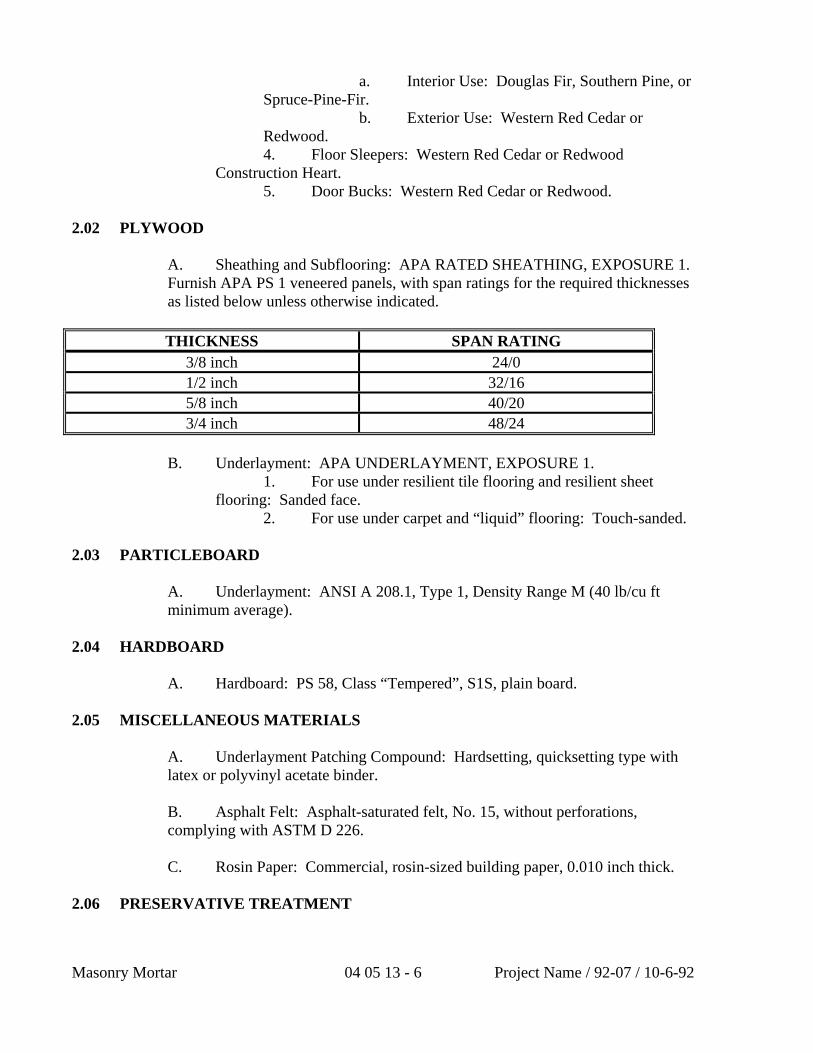
Masonry Mortar 04 05 13 - 6 Project Name / 92-07 / 10-6-92
a. Interior Use: Douglas Fir, Southern Pine, or Spruce-Pine-Fir.
b. Exterior Use: Western Red Cedar or Redwood.
4. Floor Sleepers: Western Red Cedar or Redwood Construction Heart.
5. Door Bucks: Western Red Cedar or Redwood. 2.02 PLYWOOD A. Sheathing and Subflooring: APA RATED SHEATHING, EXPOSURE 1.
Furnish APA PS 1 veneered panels, with span ratings for the required thicknesses as listed below unless otherwise indicated.
THICKNESS SPAN RATING
3/8 inch 24/0 1/2 inch 32/16 5/8 inch 40/20 3/4 inch 48/24
B. Underlayment: APA UNDERLAYMENT, EXPOSURE 1. 1. For use under resilient tile flooring and resilient sheet
flooring: Sanded face. 2. For use under carpet and “liquid” flooring: Touch-sanded. 2.03 PARTICLEBOARD A. Underlayment: ANSI A 208.1, Type 1, Density Range M (40 lb/cu ft
minimum average). 2.04 HARDBOARD A. Hardboard: PS 58, Class “Tempered”, S1S, plain board. 2.05 MISCELLANEOUS MATERIALS A. Underlayment Patching Compound: Hardsetting, quicksetting type with
latex or polyvinyl acetate binder. B. Asphalt Felt: Asphalt-saturated felt, No. 15, without perforations,
complying with ASTM D 226. C. Rosin Paper: Commercial, rosin-sized building paper, 0.010 inch thick. 2.06 PRESERVATIVE TREATMENT
Project Name / 92-07 / 10-6-92 04 05 13 - 7 Masonry Mortar
A. Treat lumber and plywood where indicated and as specified. Comply with applicable AWPA and AWPB Standards and quality control and inspection requirements.
1. Fasteners and anchoring devices to be used with wood treated with waterbourne preservatives shall be hot-dipped galvanized or stainless steel if the wood will be exposed to moisture.
B. Complete fabrication of items to be treated to the greatest extent possible
prior to treatment. Where items must be cut after treatment, coat cut surfaces with heavy brush coat of the same chemical used for treatment or other solution recommended by AWPA Standards for the treatment.
C. Inspect wood after treating and drying. Discard warped or twisted items. D. Pressure Treatment (Above Ground Use): Treat the following wood items
with waterbourne preservatives for above ground use, complying with AWPB LP-2. Redry wood to a maximum moisture content of 19 percent after treatment.
1. Nailers, blocking, cants, shim stock, and similar members used in conjunction with roofing (including related flashings, trim and vapor barrier), coping, and waterproofing.
2. Nailers, blocking, furring, stripping, and similar concealed members in contact with exterior masonry and concrete (including interior wythe of exterior walls), and all sills for framing.
3. Wood items indicated or scheduled on the Drawings to be preservative treated.
E. Pressure Treatment (Ground Contact Use): Treat the following wood
items with waterbourne preservatives for below ground use, complying with AWPB LP-22:
1. Wood members placed in the ground. 2. Wood members immersed in fresh water. F. Dip Treatment: Treat the following wood items with a 3 minute dip in 5
percent solution of pentachlorophenol with water repellant added: 1. 2. 2.07 FIRE-RETARDANT TREATMENT A. Furnish “FR-S” lumber where indicated, complying with AWPA
Standards for pressure impregnation with fire-retardant chemicals to achieve a flamespread rating of 25 or less, when tested in accordance with UL Test 723, ASTM E 84 or NFPA Test 255.
1. Where treated items are indicated to receive a transparent or paint finish, use a fire-retardant treatment which will not bleed through or adversely affect bond of finish.
2. Provide UL label or identifying mark on each piece of fire-retardant lumber.
Masonry Mortar 04 05 13 - 8 Project Name / 92-07 / 10-6-92
3. Redry treated items to a maximum moisture content of 19 percent after treatment.
2.08 FRAMING HARDWARE A. Fasteners and Anchoring Devices: Select and furnish items of type, size,
style, grade, and class as required for secure installation of the Work. Items shall be galvanized for exterior use. Unless shown or specified otherwise, comply with the following:
1. Nails and Staples: FS FF-N-105. 2. Wood Screws: FS FF-S-111. 3. Bolts and Studs: FS FF-B-575. 4. Nuts: FS FF-N-836. 5. Washers: FS FF-W-92. 6. Lag Bolts or Lag Screws: FS FF-B-561. 7. Masonry Anchoring Devices: Expansion shields, masonry
nails and drive screws: FS FF-S-325. 8. Toggle Bolts: FS FF-B-588. 9. Bar or Strap Anchors: ASTM A575 carbon steel bars. 10. Wall Plugs: Corrugated type, galvanized steel, 24 USS
gage min, not less than 2 inches wide x 2-1/2 inches deep. 11. Cross Bridging: Nailable type, galvanized steel, 16 USS
gage min, by 3/4 inch wide. 12. Metal Hangers and Framing Anchors: Size and type for
intended use, galvanized finish, manufacturer’s recommended fasteners. 13. Buck Anchors: Corrugated type, galvanized steel not
lighter than 12 USS gage min, 4 inches wide (except where partitions are less than 4 inches thick) by 8 inches long, punched for two 5/16 inch carriage bolts at buck end.
14. Sleeper Anchors: Approved type, galvanized steel not lighter than 20 USS gage min, not less than 1-1/4 inches wide, designed to anchor into concrete not less than 1-1/2 inches and permit height adjustment of sleeper.
PART 3 EXECUTION 3.01 EXAMINATION A. Verification of Conditions: Examine substrate and supporting structure on
which rough carpentry is to be installed for defects that will adversely affect the execution and quality of the Work. Do not proceed with installation until unsatisfactory conditions are corrected.
3.02 INSTALLATION - GENERAL
Project Name / 92-07 / 10-6-92 04 05 13 - 9 Masonry Mortar
A. Do not use units of material with defects which impair the quality of the Work and units which are too small to fabricate the Work with minimum joints or with optimum joint arrangement.
B. Install Work accurately to required lines and levels with members plumb
and true, accurately cut and fitted and securely fastened. Closely fit rough carpentry to other associated construction.
C. Securely attach carpentry Work to substrates by anchoring and fastening
as indicated or, if not indicated, as required by the referenced standards. Select fasteners of size that will not penetrate through members where opposite side will be exposed to view or will receive finish materials. Make tight connections between members. Install fasteners without splitting wood; predrill as required. Set nail heads in exposed Work which is to be painted or stained and fill resulting holes.
D. Treated Wood: Apply heavy brush coat of treatment material to field cut
surfaces. 3.03 WOOD FRAMING A. Install framing members of nominal sizes indicated or of units built-up to
dimensions indicated, on spacings shown. Unless otherwise indicated, comply with the recommendations of the AFPA “Manual for Wood Frame Construction”. Construct required openings for installation of related work. Do not splice structural members between supports.
B. Anchor and nail members as indicated. If not indicated, comply with the
“Recommended Nailing Schedule - Table 1” of the “Manual for Wood Frame Construction” and other applicable recommendations of the AFPA.
C. Install miscellaneous blocking and framing indicated and as required for
attachment and support of facing materials, fixtures, specialty items, and trim. D. Firestop concealed spaces with wood blocking not less than 2 inches thick,
if not blocked by other framing members. Install blocking at each building story level and at ends of each joist.
E. Stud Framing: Install stud framing indicated. Unless otherwise shown,
use 2 x 4 inch wood studs spaced 16 inches oc with 4 inch face perpendicular to direction of wall or partition. Install single bottom plate and double top plates 2 inches thick by width of studs; except single top plate may be used for non-load-bearing partitions. Nail or anchor plates to supporting construction.
1. Construct corners and intersections with not less than 3 studs. Frame openings with multiple studs and headers. Install nailed header members of thickness equal to width of studs.
2. Install diagonal bracing in exterior wall stud framing unless otherwise indicated. Brace both walls at each external corner, full story
Masonry Mortar 04 05 13 - 10 Project Name / 92-07 / 10-6-92
height, at 45 degree angle. Use either a let-in 1 x 4 inch board or 2 x 4 inch blocking.
F. Joist Framing: Install framing of sizes and on spacings shown. Install
with crown edge up and support ends of each member with not less than 1-1/2 inches of bearing on wood or metal, or 3 inches on masonry. Attach to wood bearing members by toe nailing or metal connectors; frame to wood supporting members with wood ledgers or with metal connectors. Fire-cut members built into masonry (if any). Frame openings with headers and trimmers supported by metal joist hangers; double headers and trimmers where span of header exceeds 4 feet. Do not notch in middle third of joists; limit notches to 1/6-depth of joist, 1/4 at ends. Do not bore holes larger than 1/3-depth of joist or locate closer than 2 inches from top or bottom. Install solid blocking (2 inches thick by depth of joist) at ends of joists unless nailed to header or band member.
1. Lap members framing from opposite sides of beams, girders or partitions not less than 4 inches or securely tie opposing members together. Install solid blocking (2 inches thick by depth of joist) over supports.
2. Anchor masonry bearing members with 1/4 x 1-1/4 inch metal strap or “T” anchors with wall ends bent 4 inches at every second joist. Extend anchors not less than 1’-4” along bottom of joist end and nail.
3. Anchor members paralleling masonry with 1/4 x 1-1/4 inch metal strap anchors spaced not more than 8 feet oc. Extend anchors at least 4 inches into masonry, turn up 4 inches and extend over and fasten to 3 joists.
4. Install solid blocking between joists under jamb studs at openings.
5. Under non-load-bearing partitions, install double joists separated by solid blocking equal to depth of studs above.
a. Install triple-joists separated as above, under partitions receiving ceramic tile and similar heavy finishes or fixtures, unless otherwise shown.
G. Install bridging between joists where nominal depth-to-thickness ratio
exceeds 4, at intervals of 8 feet. 3.04 WOOD NAILERS, BLOCKING, AND GROUNDS A. Install required items where indicated and where required for support,
attachment or screeding of other Work. Form to shapes indicated or required. Coordinate locations and cut and shim as required to provide items at true and level planes to receive Work to be attached. Install closure strips for nailers at all edges.
1. Attach to substrates as indicated; if not indicated, size and space fasteners as required to support applied loading. Maximum spacing of fasteners shall not exceed 16 inches. Unless otherwise shown on the Drawings, install and secure material to non-wood construction as follows:
Project Name / 92-07 / 10-6-92 04 05 13 - 11 Masonry Mortar
a. To Concrete: Attach material less than 1-1/2 inches thick with screws and non-ferrous metal expansion shields. Attach material 1-1/2 inches and thicker with machine bolts and non-ferrous metal compound type anchors.
b. To Concrete Unit Masonry: Attach material to new masonry with annular ring nails driven into wall plugs where fastening occurs at joints of masonry or with special hardened steel masonry nails where fastening occurs in the masonry units. Attach material to existing masonry with machine screws and non-ferrous metal expansion shields where fastening occurs in solid portions of masonry. If fastening occurs at cells of masonry, secure material in place with toggle bolts.
c. To Brick Masonry: Attach material to new masonry with annular ring nails driven into wall plugs. Attach material to existing masonry with machine screws and non-ferrous metal expansion shields.
d. To Steel: Attach material with galvanized bolts and nuts or stainless steel machine screws tapped into the metal, as required by conditions.
e. To Non-Ferrous Metal: Attach material with stainless steel or other approved non-ferrous metal bolts and nuts or self-tapping screws, as required by conditions.
2. Counter-sink bolts and nuts flush with surfaces, unless otherwise shown. Build into masonry during installation of masonry Work. Where possible, anchor to formwork before concrete placement. Bevel both edges of members to be anchored in concrete. Shims shall be cedar shingles or redwood wedges.
3. Install permanent grounds of dressed, preservative treated, key- beveled lumber not less than 1-1/2 inches wide and of the thickness required to bring face of ground to exact thickness of finish material involved. Remove temporary grounds when no longer required.
3.05 PLYWOOD SHEATHING, SUBFLOORING, AND UNDERLAYMENT A. Comply with printed installation requirements of the APA Design/
Construction Guide, Residential & Commercial for plywood application required, unless otherwise indicated.
B. Plywood Underlayment: Install underlayment just prior to installation of
finish flooring. Stagger end joints between panels in relation to each other and stagger all joints in relation to substrate jointing. Allow 1/32 inch space between panel ends and edges for expansion. Fasten in accordance with APA recommendations. Prior to installation of finish flooring, patch damaged areas wider than 1/16 inch. Set nails 1/16 inch, but do not fill. Sand rough areas smooth and uneven joints flush.
3.06 PARTICLEBOARD UNDERLAYMENT
Masonry Mortar 04 05 13 - 12 Project Name / 92-07 / 10-6-92
A. Install underlayment in accordance with National Particleboard Association recommendations for the type of subfloor condition. Fasten to subflooring in accordance with APA recommendations. Patch and sand gouges, gaps, and chipped edges. Sand uneven joints flush.
1. Nail underlayment to subflooring. 2. Glue-nail underlayment to subflooring. 3.07 WOOD FURRING A. Install members plumb and level with closure strips at all edges. Shim
with wood as required to achieve tolerance specified. 1. Fastening: Attach to substrates as indicated; if not
indicated, attach material as specified for nailers and blocking. 2. Tolerance: Shim and level wood furring to a tolerance of
1/8 inch in 10 feet. 3. Firestop furred spaces on walls at each floor level, with
wood blocking or other approved non-combustible materials. Fit members accurately to close furred spaces.
4. Furring to Receive Plywood Paneling: Unless otherwise indicated, 1 x 3 inch furring at 2 feet oc, horizontally and vertically.
5. Furring to Receive Gypsum Drywall: Unless otherwise indicated, 1 x 2 inch furring at 16 inches oc, vertically.
6. Furring to Receive Plaster Lath: Unless otherwise indicated, 1 x 2 inch furring at 16 inches oc, vertically.
7. Suspended Furring: Size and spacing indicated, including hangers and attachment devices.
3.08 FLOOR SLEEPERS A. Unless otherwise indicated, install 3 x 3 inch strips, 12 inches oc and
across abutting walls and restricting features. Anchor to slab with sleeper anchors 16 inches oc. Shim level to required height with redwood wedges 8 inches oc. Fill space between sleepers and floor slab solid with 1 part Portland cement and 2-1/2 parts sand mortar.
END OF SECTION
Elderly Apartment/ 4-28-06 06 11 13 - 1 2x6 Wood Studs
SECTION 06 11 13
2x6 WOOD STUDS
PART 1 GENERAL
1.01 SECTION INCLUDES
A. 2x6 wood studs
1.02 RELATED SECTIONS
A. Section 06 01 00 – Wood Repair, Restoration, and Cleaning
B. Section 06 05 73 – Wood Treatment
C. Section 06 12 00 – Wood Product Panels.
D. Section 06 17 00 – Fabricated Wood Framing
E. Section 06 48 00 – Wood Frames
F. Section 06 66 00 – Simulated Wood
1.03 REFERENCES
A. ASTM Volume 04.10 Wood
B. ASTM WK3155 – Revision of D9-87(1999) Standard Terminology Relating to Wood
C. ASTM E69 – Standard Test Method for Combustible Properties of Treated Wood by the Fire-Tube Apparatus
D. ASTM E661 – Standard Test Method for Performance of Wood
E. ASTM E695 – Standard Method for Measuring Relative Resistance of Wall, Floor, and Roof Construction to Impact Loading
F. ASTM D2555-06 – Standard Practice for Establishing Clear Wood Strength Values
1.04 DELIVERY, STORAGE, AND HANDLING
A. Deliver products to site under provisions of Section 01 65 00.
B. Store and protect products under provisions of Section 01 66 00.
C. Protect wood from excessive moisture and humidity
1.05 ENVIRONMENTAL REQUIREMENTS
2x6 Wood Studs 06 11 13 - 2 Elderly Apartment/ 4-28-06
A. Requirements: Western Wood Preservers Institute requirements.
PART 2 PRODUCTS
2.01 MATERIALS
A. Wood shall be southern pine and treated as per Section 06 05 73
B. Wood shall be in 2”x6” units
PART 3 EXECUTION
3.01 INSTALLATION
A. Installer must meet qualifications in section 01 43 00.
B. Install wood studs in conjunction with Sections 06 06 00 and 06 11 00.
3.02 FIELD QUALITY CONTROL
A. Field testing will be performed under provisions of Section 01 45 00.
END OF SECTION
SECTION 06 16 00
SHEATHING
PART 1 GENERAL 1.1 SECTION INCLUDES
A. Oriented strand board (OSB) panel floor sheathing.
B. Oriented strand board (OSB) panel subflooring. 1.2 RELATED SECTIONS
A. Section 06100 - Rough Carpentry: Installation and requirements for wood composite backing panels.
B. Section 06163 - Underlayment: Installation and requirements for floor
underlayment.
C. Section 07212 - Radiant Barriers; OSB panels with a radiant barrier.
D. Section 07260 - Vapor Retarders: Installation and requirements for vapor retarders.
E. Section 07270 - Air and Moisture Barriers: Installation and
requirements for air and moisture barriers.
F. Section 09600 - Flooring: Installation and requirements for finish flooring.
1.3 REFERENCES
A. APA The Engineered Wood Association (APA): 1. APA AFG, specification for field gluing subfloors. 2. APA Exposure 1 and Sturd-I-Floor construction requirements. 3. APA Form No. E30R, Engineered Wood Construction Guide. 4. APA PRP-108: Performance Standards and Qualification Policy
for Structural-Use Panels.
B. Canadian Standards Association (CSA): 1. CSA 0325 - Construction Sheathing. 2. CSA 0437 - OSB and Waferboard.
1.4 SUBMITTALS
Elderly Apartment 11/27/2006 06 16 00 - 1 Sheathing
A. Submit under provisions of Section 01300.
B. [ Product Data ]: Manufacturer's data sheets on each product to be used, including: 1. Wood preservative treatment data and certification. 2. Fire retardant treatment data and certification. 3. Preparation instructions and recommendations. 4. Storage and handling requirements and recommendations. 5. Installation methods.
1.5 QUALITY ASSURANCE
A. Provide products in compliance with APA Exposure 1 and Sturd-I-Floor construction requirements.
B. Provide products in compliance with CSA 0325 and CSA 0437.
1.6 DELIVERY, STORAGE, AND HANDLING
A. Store products in manufacturer's unopened packaging with labels intact until ready for installation.
B. Store products in clean, dry area indoors and under cover, stacked on
pallets.
C. Store products under water resistant cover. Keep cover open and away from sides and bottom of panels to allow for air circulation.
D. Identify products with the markings of applicable testing and
inspecting organizations and APA Sturd-I-Floor rating. 1.7 PROJECT CONDITIONS
A. Maintain environmental conditions (temperature, humidity, and ventilation) within limits recommended by manufacturer for optimum results. Do not install products under environmental conditions outside manufacturer's absolute limits.
B. Acclimatize panels to existing moisture conditions before installation.
1.8 WARRANTY
A. Manufacturer's standard limited lifetime warranty against material and manufacturing defects.
B. Manufacturer's standard 90 day warranty against sanding due to
Elderly Apartment 11/27/2006 06 16 00 - 2 Sheathing
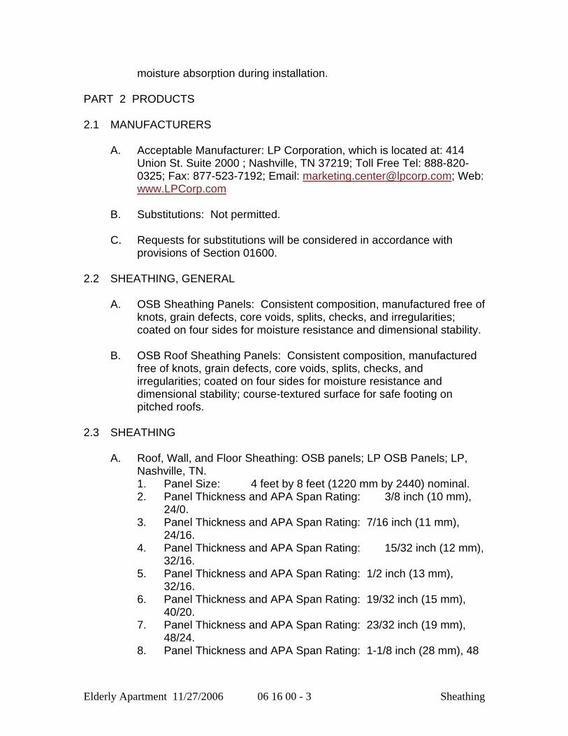
moisture absorption during installation. PART 2 PRODUCTS 2.1 MANUFACTURERS
A. Acceptable Manufacturer: LP Corporation, which is located at: 414 Union St. Suite 2000 ; Nashville, TN 37219; Toll Free Tel: 888-820-0325; Fax: 877-523-7192; Email: [email protected]; Web: www.LPCorp.com
B. Substitutions: Not permitted.
C. Requests for substitutions will be considered in accordance with
provisions of Section 01600. 2.2 SHEATHING, GENERAL
A. OSB Sheathing Panels: Consistent composition, manufactured free of knots, grain defects, core voids, splits, checks, and irregularities; coated on four sides for moisture resistance and dimensional stability.
B. OSB Roof Sheathing Panels: Consistent composition, manufactured
free of knots, grain defects, core voids, splits, checks, and irregularities; coated on four sides for moisture resistance and dimensional stability; course-textured surface for safe footing on pitched roofs.
2.3 SHEATHING
A. Roof, Wall, and Floor Sheathing: OSB panels; LP OSB Panels; LP, Nashville, TN. 1. Panel Size: 4 feet by 8 feet (1220 mm by 2440) nominal. 2. Panel Thickness and APA Span Rating: 3/8 inch (10 mm),
24/0. 3. Panel Thickness and APA Span Rating: 7/16 inch (11 mm),
24/16. 4. Panel Thickness and APA Span Rating: 15/32 inch (12 mm),
32/16. 5. Panel Thickness and APA Span Rating: 1/2 inch (13 mm),
32/16. 6. Panel Thickness and APA Span Rating: 19/32 inch (15 mm),
40/20. 7. Panel Thickness and APA Span Rating: 23/32 inch (19 mm),
48/24. 8. Panel Thickness and APA Span Rating: 1-1/8 inch (28 mm), 48
Elderly Apartment 11/27/2006 06 16 00 - 3 Sheathing
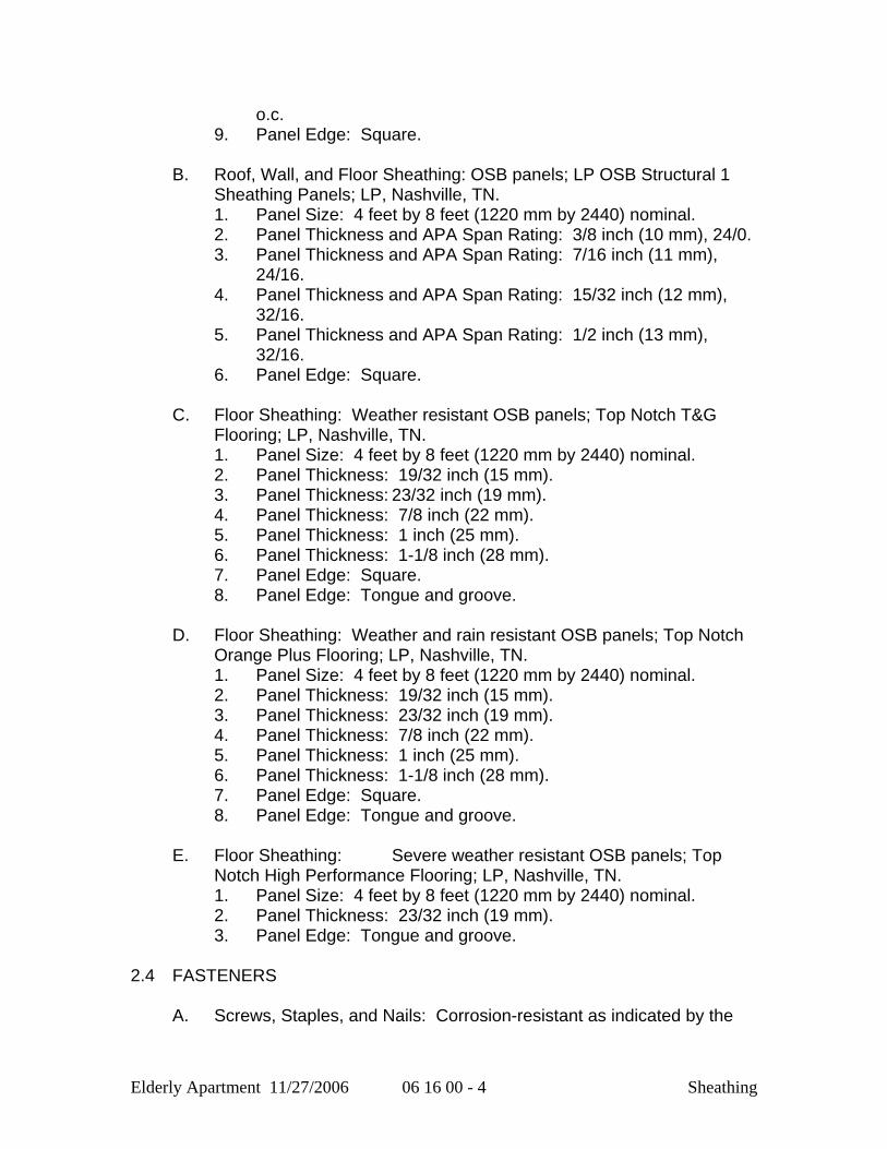
o.c. 9. Panel Edge: Square.
B. Roof, Wall, and Floor Sheathing: OSB panels; LP OSB Structural 1
Sheathing Panels; LP, Nashville, TN. 1. Panel Size: 4 feet by 8 feet (1220 mm by 2440) nominal. 2. Panel Thickness and APA Span Rating: 3/8 inch (10 mm), 24/0. 3. Panel Thickness and APA Span Rating: 7/16 inch (11 mm),
24/16. 4. Panel Thickness and APA Span Rating: 15/32 inch (12 mm),
32/16. 5. Panel Thickness and APA Span Rating: 1/2 inch (13 mm),
32/16. 6. Panel Edge: Square.
C. Floor Sheathing: Weather resistant OSB panels; Top Notch T&G
Flooring; LP, Nashville, TN. 1. Panel Size: 4 feet by 8 feet (1220 mm by 2440) nominal. 2. Panel Thickness: 19/32 inch (15 mm). 3. Panel Thickness: 23/32 inch (19 mm). 4. Panel Thickness: 7/8 inch (22 mm). 5. Panel Thickness: 1 inch (25 mm). 6. Panel Thickness: 1-1/8 inch (28 mm). 7. Panel Edge: Square. 8. Panel Edge: Tongue and groove.
D. Floor Sheathing: Weather and rain resistant OSB panels; Top Notch
Orange Plus Flooring; LP, Nashville, TN. 1. Panel Size: 4 feet by 8 feet (1220 mm by 2440) nominal. 2. Panel Thickness: 19/32 inch (15 mm). 3. Panel Thickness: 23/32 inch (19 mm). 4. Panel Thickness: 7/8 inch (22 mm). 5. Panel Thickness: 1 inch (25 mm). 6. Panel Thickness: 1-1/8 inch (28 mm). 7. Panel Edge: Square. 8. Panel Edge: Tongue and groove.
E. Floor Sheathing: Severe weather resistant OSB panels; Top
Notch High Performance Flooring; LP, Nashville, TN. 1. Panel Size: 4 feet by 8 feet (1220 mm by 2440) nominal. 2. Panel Thickness: 23/32 inch (19 mm). 3. Panel Edge: Tongue and groove.
2.4 FASTENERS
A. Screws, Staples, and Nails: Corrosion-resistant as indicated by the
Elderly Apartment 11/27/2006 06 16 00 - 4 Sheathing
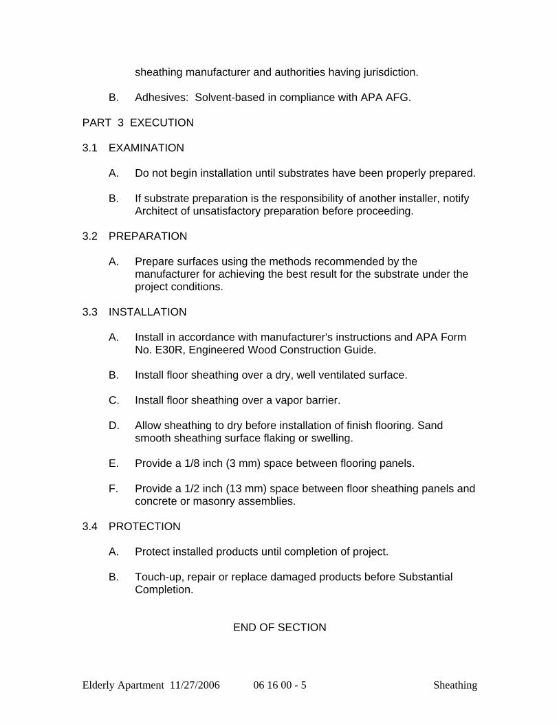
sheathing manufacturer and authorities having jurisdiction.
B. Adhesives: Solvent-based in compliance with APA AFG. PART 3 EXECUTION 3.1 EXAMINATION
A. Do not begin installation until substrates have been properly prepared.
B. If substrate preparation is the responsibility of another installer, notify Architect of unsatisfactory preparation before proceeding.
3.2 PREPARATION
A. Prepare surfaces using the methods recommended by the manufacturer for achieving the best result for the substrate under the project conditions.
3.3 INSTALLATION
A. Install in accordance with manufacturer's instructions and APA Form No. E30R, Engineered Wood Construction Guide.
B. Install floor sheathing over a dry, well ventilated surface.
C. Install floor sheathing over a vapor barrier.
D. Allow sheathing to dry before installation of finish flooring. Sand
smooth sheathing surface flaking or swelling.
E. Provide a 1/8 inch (3 mm) space between flooring panels.
F. Provide a 1/2 inch (13 mm) space between floor sheathing panels and concrete or masonry assemblies.
3.4 PROTECTION
A. Protect installed products until completion of project.
B. Touch-up, repair or replace damaged products before Substantial Completion.
END OF SECTION
Elderly Apartment 11/27/2006 06 16 00 - 5 Sheathing

Elderly Apartment 11/27/2006 06 16 00 - 6 Sheathing
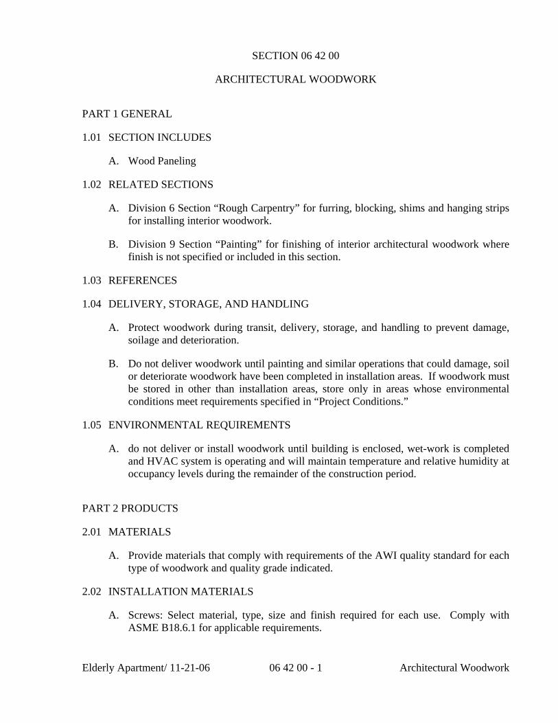
Elderly Apartment/ 11-21-06 06 42 00 - 1 Architectural Woodwork
SECTION 06 42 00
ARCHITECTURAL WOODWORK
PART 1 GENERAL
1.01 SECTION INCLUDES
A. Wood Paneling
1.02 RELATED SECTIONS
A. Division 6 Section “Rough Carpentry” for furring, blocking, shims and hanging strips for installing interior woodwork.
B. Division 9 Section “Painting” for finishing of interior architectural woodwork where finish is not specified or included in this section.
1.03 REFERENCES
1.04 DELIVERY, STORAGE, AND HANDLING
A. Protect woodwork during transit, delivery, storage, and handling to prevent damage, soilage and deterioration.
B. Do not deliver woodwork until painting and similar operations that could damage, soil or deteriorate woodwork have been completed in installation areas. If woodwork must be stored in other than installation areas, store only in areas whose environmental conditions meet requirements specified in “Project Conditions.”
1.05 ENVIRONMENTAL REQUIREMENTS
A. do not deliver or install woodwork until building is enclosed, wet-work is completed and HVAC system is operating and will maintain temperature and relative humidity at occupancy levels during the remainder of the construction period.
PART 2 PRODUCTS
2.01 MATERIALS
A. Provide materials that comply with requirements of the AWI quality standard for each type of woodwork and quality grade indicated.
2.02 INSTALLATION MATERIALS
A. Screws: Select material, type, size and finish required for each use. Comply with ASME B18.6.1 for applicable requirements.
Elderly Apartment/ 11-21-06 06 42 00 - 2 Architectural Woodwork
B. Nails: Select material, type, size and finish required for each use. Comply with FS-FF-N-105 for applicable requirements.
C. Anchors: Select material, type, size and finish required for each substrate for secure anchorage. Provide nonferrous metal or hot-dip galvanized anchors and inserts on inside face of exterior walls and elsewhere as required for corrosion resistance. Provide toothed steel or lead expansion bolt devices for drilled in place anchors.
PART 3 EXECUTION
3.01 INSTALLATION
A. Quality Standard: Install woodwork to comply with AWI Section 1700 for the same grade specified in Part 2 of this Section for type of woodwork involved.
B. Install woodwork plumb, level, true and straight with no distortions. Shim as required with concealed shims. Install to a tolerance of 1/8th inch in 96 inches for plumb and level.
C. Scribe and cut woodwork to fit adjoining work and refinish cut surfaces or repair damaged finish at cuts.
D. Anchor woodwork to anchors or blocking built in or directly attached to substrates. Secure to grounds, stripping and blocking with countersunk, concealed fasteners and blind nailing as required for complete installation. Use fine finishing nails for exposed nailing, countersunk and filled flush with woodwork and matching final finish where transparent finish is indicated.
E. Anchor paneling to supporting substrate with concealed panel-hanger clips and by blind nailing on backup strips, splined-connection strips and similar associated trim and framing. Do not face nail unless otherwise indicated.
1. Install flush paneling with no more than 1/16th inch in 96 inch horizontal variation from a true plane.
3.02 FIELD QUALITY CONTROL
A. Field testing will be performed under provisions of this Section.
END OF SECTION
SECTION 06 47 01
CLOSET DOORS
GENERAL
1.1 SECTION INCLUDES
A. Closet Doors.
1.2 RELATED SECTIONS
A. Section 09 09 00 - Paints and Coatings.
1.3 SUBMITTALS
A. Submit under provisions of Section 01 03 00.
B. [ Product Data ]: Manufacturer's data sheets on each product to be used, including: 1. Materials, dimensions, profiles, fasteners and anchors, hardware, finishes,
and interface with adjacent construction 2. Storage and handling requirements and recommendations. 3. Installation methods. 4. Field finishing instruction, to be forwarded to paint applicator.
1.4 DELIVERY, STORAGE, AND HANDLING
A. Deliver materials to site in manufacturer's original, packaging, with labels clearly identifying product name and manufacturer.
B. Store products in manufacturer's packaging until ready for installation.
C. Store materials in a clean, dry area in accordance with manufacturer's instructions.
D. Protect materials during handling and installation to prevent damage.
PART 2 PRODUCTS
2.1 MANUFACTURER
A. Acceptable Manufacturer: Kestrel Shutters, which is located at: 9 E. Race St. ; Stowe, PA 19464; Toll Free Tel: 800-494-4321; Tel: 610-326-6679; Fax: 610-326-6779; Email: [email protected]; Web: www.DIYShutters.com
B. Requests for substitutions will be considered in accordance with provisions of Section 01 06 00.
2.2 CLOSET DOORS
A. General: Interior closet doors FAS grade clear, kiln dried Basswood; frames constructed with pegged, mortise and tenon joints. Louver blades solid 3/8 inch (9.5 mm) thick and mortised into the stiles. Frame thickness as follows: 1. 1-1/4 inch (32 mm).
PART 3 EXECUTION
Closet Doors 06 47 01-1 Elderly Apartment/11-21-06
3.1 EXAMINATION
A. Do not begin installation until substrates have been properly prepared.
B. If substrate preparation is the responsibility of another installer, notify Architect of any unsatisfactory preparation before proceeding.
C. Commencement of work will imply acceptance of substrate.
3.2 PREPARATION
A. Clean surfaces thoroughly prior to installation.
B. Prepare surfaced using the methods recommended by the manufacturer for achieving the best result for the substrate under the project conditions.
3.3 INSTALLATION
A. Install in accordance with manufacturer's instructions.
3.4 PROTECTION
A. Protect exterior work from weather until paint or transparent finish is applied.
B. Protect installed products from damage by weather and other work until Date of Substantial Completion.
C. Touch-up and repair damaged products before Date of Substantial Completion.
D. Replace damaged products where touch-up or repair cannot be made indistinguishable from undamaged products.
END OF SECTION
Closet Doors 06 47 01-2 Elderly Apartment/11-21-06

Exterior Insulation
SECTION 07 21 00
BUILDING INSULATION
PART 1 GENERAL
1.01 SUMMARY
A. Section includes: Expanded Polystyrene (EPS) Insulation used as building insulation.
1.02 REFERENCES
A. General: Standards listed by reference, including revisions by issuing authority, form a part of this specification section to the extent indicated. Standards listed are identified by issuing authority, authority abbreviation, designation number, title or other designation established by issuing authority. Standards subsequently referenced herein are referred to by issuing authority abbreviation and standard designation.
B. American Society for Testing and Materials (ASTM):
1. ASTM C578 Standard Specification for Rigid, Cellular Polystyrene Thermal Insulation.
2. ASTM E84 Standard Test Method for Surface Burning Characteristics of Building Materials.
C. Factory Mutual Research Corporation (FMRC):
1. Factory Mutual Research Corporation Approval Guide (current edition). Contact manufacturer for approval standard and number.
1.03 DELIVERY, STORAGE & HANDLING
A. General: Comply with Division 1 Product Requirement Section.
B. Comply with manufacturer’s ordering instructions and lead time requirements to avoid construction delays.
C. Delivery: Deliver materials in manufacturer’s original, unopened, undamaged containers with identification labels intact.
D. Storage and Protection: Store materials protected from exposure to harmful environmental conditions and at temperature and humidity conditions recommended by the manufacturer.
Elderly Apartment / 11-21-06 07 21 00 – 1 Building Insulation
1. Prolonged exposure to sunlight will cause slight discoloration and surface dusting of EPS insulation.
2. EPS insulation exposed to moisture should be replaced or thoroughly dried prior to application of finish orcovering materials.
PART 2 PRODUCTS
2.01 EPS INSULATION BOARD
A. Manufacturer: EPS Molders Association.
1. Contact: 1298 Cronson Blvd., Crofton, MD 21114; Telephone: (800) 607-3772; Fax: (410) 451-8343; website:www.epsmolders.org.
B. Proprietary Products/Systems: EPS insulation boards, including the following:
1. Flat Stock Board:
a. Material Description: Rigid, closed cell, expanded polystyrene (EPS) board stock.
b. Material Standard: Comply with ASTM C578.
c. Thickness: [Specify thickness.].
d. Nominal Density: [1.0 pcf (Type I)] [1.25 pcf (Type VIII)] [1.5 pcf (Type II)] [2.0 pcf (Type IX)].
e. Flamespread Index (ASTM E84): Contact manufacturer for test results.
f. Smoke Development Index (ASTM E84): Contact manufacturer for test results.
g. Facing: [Unfaced] [Foil faced (aluminum kraft paper laminate)] [Poly faced (polyethylene skin kraft paper laminate)].
2.02 PRODUCT SUBSTITUTIONS
A. Substitutions: No substitutions permitted.
2.03 ACCESSORIES
A. Provide installation accessories as follows:
1. Adhesive:
Building Insulation 07 21 00 – 2 Elderly Apartment / 11-21-06
a. Material, Type and Manufacturer: [Compatible with EPS insulation board and acceptable to EPS insulation board manufacturer] [Specify material, type and manufacturer.].
2. Wall Ties:
a. Material, Type and Manufacturer: [Compatible with EPS insulation board and acceptable to EPS insulation board manufacturer] [Specify material, type and manufacturer.].
3. Mechanical Fasteners:
a. Material Type and Manufacturer: [Compatible with EPS insulation board and acceptable to EPS insulation board manufacturer] [Specify material, type and manufacturer.].
4. Furring Channels:
a. Material, Type and Manufacturer: [Compatible with EPS insulation board and acceptable to EPS insulation board manufacturer] [Specify material, type and manufacturer.].
PART 3 EXECUTION
3.01 INSTALLATION
A. Comply with the instructions and recommendations of the EPS insulation board manufacturer.
3.02 EXAMINATION
A. Site Verification of Conditions:
1. Verify that site conditions are acceptable for installation of EPS insulation board.
2. Do not proceed with installation of EPS insulation board until unacceptable conditions are corrected.
3.03 INSTALLATION
A. General:
1. Install EPS board insulation in a [Single] [Double] layer to achieve required R-value(s) as indicated in drawings. Cut and fit tightly around projections and penetrations.
Building Insulation 07 21 00 – 3 Elderly Apartment / 11-21-06
2. Secure insulation to substrate with [Mechanical fasteners] [Or] [Spot adhesive applied to back of board] using quantity and pattern recommended by manufacturer.
B. Insulation Board Joints: Stagger EPS insulation board joints in one direction for each course. Butt edges and ends tightly to adjacent EPS boards.
C. Sheathing and Underlayment Installation: On exterior side of stud framing, install EPS insulation board [Vertically] [Horizontally]. Fasten vertically 12" (300 mm) maximum on centers using fasteners recommended by manufacturer. On interior side of stud framing, install minimum 1/2" (12.7 mm) thick gypsum wallboard over EPS board.
D. Concrete and Masonry Walls: Install EPS insulation board over furring channels attached to concrete and unit masonry substrates. Fasten vertically 12" (300 mm) maximum on centers using fasteners recommended by manufacturer.
E. Cavity Walls: Install EPS insulation board on exterior surface of interior wythe of cavity wall, fitting board between wall ties and other projections and penetrations.
F. Perimeter Foundation: Install EPS insulation board on exterior surface of perimeter foundation walls. Secure board with spot adhesive applied to back of board using quantity and pattern recommended by manufacturer.
G. Slab-On-Grade: Install EPS insulation board under slab-on-grade and over properly prepared subgrade of compacted fill and vapor retarder. Place EPS board with sides and ends butted.
3.04 PROTECTION
A. Protect installed work from damage due to subsequent construction activity on the site.
END OF SECTION
Building Insulation 07 21 00 – 4 Elderly Apartment / 11-21-06
Elderly Apartments 11/13/06 07 65 00 - 1 Flashing
SECTION 07 65 00
FLEXIBLE FLASHING SYSTEMS
PART 1 GENERAL 1.01 SECTION INCLUDES
A. Masonry veneer flashing system. 1.02 RELATED SECTIONS
A. Section 04810- Unit Masonry Assemblies.
B. Section 04850- Stone Assemblies.
C. Section 07600- Flashing and Sheet Metal.
D. Section 07920- Sealants. 1.03 REFERENCES
A. ASTM A 666- Standard Specification for annealed or Cold-Worked Austenitic Stainless Steel Sheet, Strip, Plate, and Flat Bar.
B. ASTM D 412- Standard Test Methods for Vulcanized Rubber and Thermoplastic
Rubbers and Thermoplastic Elastomers- Tension.
C. ASTM D 2240- Standard Test Method for Rubber Property Durometer Hardness.
1.04 DELIVERY, STORAGE, AND HANDLING
A. Store products in manufacturer’s unopened packaging until ready for installation.
B. Store and dispose of solvent-based materials, and materials used with solvent-
based materials, in accordance with requirements of local authorities having jurisdiction.
1.05 ENVIRONMENTAL REQUIREMENTS
A. Maintain environmental conditions (temperature, humidity, and ventilation) within limits recommended by manufacturer for optimum results. Do not install products under environmental conditions outside manufacturer’s absolute limits.
Elderly Apartments 11/13/06 07 65 00 - 2 Flashing
PART 2 PRODUCTS 2.01 MANUFACTURERS
A. Acceptable Acceptable Manufacturer: Hohmann & Barnard, Inc.; 30 Rasons Ct., Hauppauge, NY 11788-0270. ASD. Tel: (631) 234-0600 . Fax: (631) 234-0683. Email: [email protected]. Web: http://www.h-b.com.
B. Requests for substitutions will be considered in accordance with provisions of
Section 01600. 2.02 SYSTEM COMPONENTS
A. Provide veneer cavity flashing system where indicated or required. Provide flashing fabric and accessories as a complete assembly unless noted otherwise.
B. Flashing System:
a. Self Adhering Flexible Flashing: Flex-Flash as manufactured by Hohmann and barnard, Inc.
b. Termination Bar and Reglets: 1. Foam-Tite Seal Flange (T2-FTS) as manufactured by
Hohmann and Barnard, Inc. 2. #307 Metal Reglet as manufactured by Hohmann and
Barnard, Inc. c. Drip Plates:
1. Stainless Steel for standard installation. d. Backer Rod and Sealand: To comply with Section 07920.
2.03 MATERIALS
A. Self Adhering Flexible Flashing: a. Tensile Strength: 2000 psi (14 MPa) per ASTM D 412. b. Ultimate Elongation: 25 percent. c. Shore A Hardness: 83 per ASTM D 2240. d. Corners and End Dams: Preformed.
B. Termination Bars and Reglets:
a. Termination Bars: AISI Type 304, ASTM A 666 Stainless Steel. Predrilled ¼ inch (6 mm) holes on 8 inches (203 mm) centers.
b. Reglets: Metal reglets, 24 gage type 304 stainless steel with foam filled closure strip.
C. Drip Plates:
a. Fabrication: Suitable lengths with hemmed exposed edge and provided with inside and outside factory fabricated corners.
Elderly Apartments 11/13/06 07 65 00 - 3 Flashing
b. Stainless Steel: AISI Type 304, ASTM A 666. c. Size: As indicated d. Foam Seal: Provide 1/8 inch (3 mm) foam compressible filler adhered
to bottom of drip plate to inhibit air and moisture infiltration.
D. Relief Angle Compressible Filler: Neoprene foam filler strip placed below relief angle.
Part 3 EXECUTION 3.01 EXAMINATION
A. Do not begin installation until substrates have been properly prepared.
B. If substrate preparation is the responsibility of another installer, notify Architect of unsatisfactory preparation before preceeding.
3.02 PREPARATION
A. Clean surfaces thoroughly prior to installation.
B. Prepare surfaces using the methods recommended by the manufacturer for achieving the best result for the substrate under the project conditions.
3.03 INSTALLATION
A. Install in accordance with manufacturer’s instructions. 3.04 PROTECTION
A. Protect installed products until completion of project.
B. Touch-up, repair or replace damaged Work before proceeding with construction on or concealing work
END OF SECTION
SECTION 07 84 43
FIRE RESISTIVE JOINT SYSTEMS
PART 1 – GENERAL 1.1 RELATED DOCUMENTS
A. Drawings and general provisions of the Contract, including General and
Supplementary Conditions and Division 1 Specification Sections, apply to this Section.
1.2 SUMMARY
A. This section includes fire-resistive joint systems for linear voids within or
between fire-resistance rated floor and roof-ceiling assemblies and walls and partitions, including the following types of joints: 1. Expansion joints and control joints or joints between floor structures. 2. Floor-to-wall joints where a floor structure intersects a wall structure. 3. Head-of-wall joints where a wall or partition intersects a roof or floor-
ceiling assembly. 4. Control joints within or between wall structures.
B. Related Sections include the following:
1. Division 3 – Section 03 30 00 – Cast-In-Place Concrete 2. Division 4 – Section 04 22 00 – Concrete Unit Masonry 3. Division 7 – Section 07 21 00 – Thermal Insulation 4. Division 7 – Section 07 84 13 – Penetration Firestopping
5. Division 7 – Section 07 84 53 – Building Perimeter Firestopping 6. Division 7 – Section 07 90 00 – Joint Protection 7. Division 7 – Section 07 95 00 – Expansion Control 8. Division 9 – Section 09 20 00 – Plaster and Gypsum Board
1.3 PERFORMANCE CRITERIA
A. FIRE AND CYCLIC MOVEMENT TEST REQUIREMENTS
1. ASTM E-1966, “Test Method for Fire Resistive Joint Systems”.
Elderly Apartment / 11-21-06 078443-1 Joint System
2. ANSI/ UL2079, “Tests for Fire Resistance of Building Joint Systems”
3. ASTM E-1399, “Cyclic Movement and Measuring the Minimum and Maximum Joint Widths of Architectural Joint Systems”.
4. ASTM E-119, “Fire Tests of Building Construction and Materials”. 5. ANSI/ UL263, “Fire Tests of Building Construction and Materials”.
6. ASTM E-84, “Surface Burning Characteristics of Building Materials”. 7. ANSI/ UL723, “Surface Burning Characteristics of Building Materials”.
B. REFERENCES
1. Underwriters Laboratories (UL) of Northbrook, IL “Fire Resistance Directory”.
a. Joint Systems (XHBN)
b. Fill, Void or Cavity Materials (XHHW)
c. Forming Materials (XHKU)
2. All major building codes: ICBO, SBCCI, BOCA and IBC. (Note to specifier: Retain or delete building codes listed above as applicable).
3. National Fire Protection Association (NFPA) of Quincy, MA “NFPA 101: Life Safety Code”.
4. American Society of Testing and Materials (ASTM) of Conshohocken,
PA “ ASTM C-1193: Standard Guide for the Use of Joint Sealants”.
C. PERFORMANCE REQUIREMENTS 1. Provide products that upon curing, do not re-emulsify, dissolve, leach,
breakdown or otherwise deteriorate over time from exposure to atmospheric moisture, ponding water or other forms of moisture characteristic during and after construction.
2. Provide fire-resistive joint sealants sufficiently flexible to accommodate
movement such as thermal expansion and other normal building movement without damage to the seal.
3. Provide fire-resistive joint sealants designed to accommodate a specific
range of movement and tested for this purpose in accordance with a cyclic movement test criteria as outlined in Standards, ASTM E-1399, ASTM E-1966 or ANSI/ UL 2079.
Elderly Apartment / 11-21-06 078443-2 Joint System
4. Provide fire-resistive joint systems subjected to an air leakage test
conducted in accordance with Standard, ANSI/ UL2079 with published L-Ratings for ambient and elevated temperatures as evidence of the ability of the fire-resistive joint system to restrict the movement of smoke.
5.
1.4 SUBMITTALS
A. Product Data: For each type of fire-resistive joint system product indicated. B. System Drawings: Submit documentation from a qualified testing and inspection
agency that is applicable to each fire-resistive joint system configuration for construction and linear void width.
C. Product Certificates: Certificate of conformance signed by manufacturers of fire-
resistive joint system products certifying that products comply with requirements.
1.5 QUALITY ASSURANCE
A. Provide fire-resistive joint systems that comply with the following requirements and those specified in “Performance Criteria” Article: 1. Firestopping tests are performed by a qualified, testing and inspection
agency. A qualified testing and inspection agency is UL, or another agency performing testing and follow-up inspection services for fire-resistive joint systems acceptable to authorities having jurisdiction.
2. Fire-resistive joint system products bear classification marking of
qualified testing and inspection agency.
B. Engage an experienced installer who is certified, licensed or otherwise qualified
by the firestopping manufacturer as having been provided the necessary training to install firestop products per specified requirements. A manufacturer’s willingness to sell its fire-resistive joint system products to Contractor or to an installer engaged by Contractor does not in itself confer qualifications on buyer.
C. Obtain fire-resistive joint systems for each type of joint configuration and
construction condition indicated from a single manufacturer.
D. Conduct conference at Project site to comply with requirements in Division 1
Section “Project Meetings”.
1.6 DELIVERY, STORAGE AND HANDLING
A. Deliver fire-resistive joint system products to Project site in original, unopened containers or packages with intact and legible manufacturer’s labels identifying
Elderly Apartment / 11-21-06 078443-3 Joint System
product and manufacturer, date of manufacture; lot number; shelf life, if applicable; qualified testing and inspection agency’s classification marking; and mixing instructions for multicomponent materials.
B. Store and handle materials for fire-resistive joint systems to prevent their
deterioration or damage due to moisture, temperature changes, contaminants or other causes.
1.7 PROJECT CONDITIONS
A. Do not install fire-resistive joint systems when ambient or substrate temperatures are outside limitations recommended by manufacturer.
B. Do not install fire-resistive joint systems when substrates are wet due to rain,
frost, condensation, or other causes.
C. Do not use materials that contain flammable solvents.
PART 2 – PRODUCTS 2.1 FIRESTOPPING, GENERAL
A. Provide fire-resistive joint system products that are compatible with one another, with the substrates forming openings, under conditions of service and application, as demonstrated by fire-resistive joint system product manufacturer based on testing and field experience.
B. Provide components for each fire-resistive joint system that are needed to install
fill materials. Use only components specified by the firestopping manufacturer and approved by the qualified testing agency for the designated fire-resistance-rated systems.
2.2 ACCEPTABLE MANUFACTURERS
A. Subject to compliance with joint systems (XHBN) listed in Volume 2 of the UL Fire Resistance Directory, provide products of the following manufacturers as identified below: 1. Specified Technologies, Inc. (STI), Somerville, New Jersey
800 – 992 – 1180
2. Other manufacturers listed in the UL Fire Resistance Directory – Volume 2.
2.3 MATERIALS
A. General: Use only fire-resistive joint system products that have been tested for specific fire-resistance-rated construction conditions conforming to construction
Elderly Apartment / 11-21-06 078443-4 Joint System
assembly type, linear void width, movement capabilities, and fire-rating involved for each separate instance.
B. Latex Sealants: Single component latex formulations that upon cure do not re-
emulsify during exposure to moisture for use in interior joint applications, the following products are acceptable:
1. Specified Technologies, Inc. (STI) SpecSeal Series ES Elastomeric
Sealant 2. Specified Technologies, Inc. (STI) SpecSeal Series AS Elastomeric
Spray
C. Silicone Sealants: Moisture curing, single component, silicone elastomeric sealant for horizontal surfaces (pourable or nonsag) or vertical surface (nonsag) in interior or exterior joint applications, the following products are acceptable:
1. Specified Technologies, Inc. (STI) Pensil 300 Silicone Sealant 2. Specified Technologies, Inc. (STI) Pensil 300 SL Self-Leveling Silicone
Sealant PART 3 – EXECUTION 3.1 PREPARATION
A. Examination of Conditions: Examine areas and conditions under which work is to be performed and identify conditions detrimental to proper or timely completion.
C. Surfaces to which firestop materials will be applied shall be free of dirt, grease,
oil, scale, laitance, rust, release agents, water repellents, and any other substances that may inhibit optimum adhesion.
D. Provide masking and temporary covering to prevent soiling of adjacent surfaces
by firestopping materials.
E. Do not proceed until unsatisfactory conditions have been corrected.
3.2 FIRE-RESISTIVE JOINT SYSTEM INSTALLATION
B. General Requirements: Install fire-resistive joint systems in accordance with “Performance Criteria” Article and in accordance with the conditions of testing and classification as specified in the published design.
C. Manufacturer’s Instructions: Comply with manufacturer’s instructions for
installation of fire-resistive joint systems products.
1. Seal all joint openings to ensure an air and water resistant seal. 2. Protect materials from damage on surfaces subjected to traffic.
Elderly Apartment / 11-21-06 078443-5 Joint System
3. Apply a suitable bond-breaker to prevent three-sided adhesion in
applications where this condition might occur such as the intersection of a gypsum wallboard/steel stud wall to floor or roof assembly where the joint is backed by a steel ceiling runner or track.
4. Where joint application is exposed to the elements, fire-resistive joint
sealant must be approved by manufacturer for use in exterior applications and shall comply with ASTM C-920, “Specification for Elastomeric Joint Sealants”.
3.3 FIELD QUALITY CONTROL
A. Inspections: Owner shall engage a qualified independent inspection agency to inspect fire-resistive joint systems.
B. Keep areas of work accessible until inspection by authorities having jurisdiction.
C. Where deficiencies are found, repair or replace fire-resistive joint systems so they
comply with requirements.
3.4 ADJUSTING AND CLEANING
A. Remove equipment, materials and debris, leaving area in undamaged, clean condition.
B. Clean all surfaces adjacent to sealed joint openings to be free of excess fire-
resistive joint system materials and soiling as work progresses.
END OF SECTION
Elderly Apartment / 11-21-06 078443-6 Joint System
Elderly Apartment / 4-28-06 08 11 13 HM Doors and Frames
SECTION 08 11 13
HOLLOW METAL DOORS AND FRAMES
PART 1 GENERAL
1.01 SUMMARY
A. Section Includes: Prefinished and primed steel door frames for interior and exterior doors, including sidelites, borrowed lites and transom assemblies.
1. Frame Type: Fixed throat door frame type, double rabbet profile with integral stops. 2. Frame Type: Fixed throat door frame with formed kerf pocket to accept weatherstrip.
B. Related Sections: Section(s) related to this section include:
1. Metal Doors: Division 08 Steel Door Section.
2. Wood Doors: Division 08 Wood Door Section.
3. Finish Hardware: Division 08 Hardware Section.
4. Glass and Glazing: Division 08 Glass and Glazing Sections.
1.02 REFERENCES
A. General: Standards listed by reference, including revisions by issuing authority, form a part of this specification section to extent indicated. Standards listed are identified by issuing authority, authority abbreviation, designation number, title, or other designation established by issuing authority. Standards subsequently referenced herein are referred to by issuing authority abbreviation and standard designation. B. ASTM International:
1. ASTM A366 Standard Specification for Commercial Steel (CS) Sheet, Carbon (0.15 Maximum Percent) Cold-Rolled 2. ASTM A653 Standard Specification for Steel Sheet, Zinc-Coated (Galvanized) or Zinc-Iron Alloy-Coated (Galvannealed) by the Hot-Dip Process. 3. ASTM B117 Standard Practice for Operating Salt Spray (Fog) Apparatus. 4. ASTM D1735 Standard Practice for Testing Water Resistance of Coatings Using Water Fog Apparatus.
Elderly Apartment / 4-28-06 08 11 13 HM Doors and Frames
C. Steel Door Institute (SDI):
1. SDI-107 Hardware on Steel Doors (Reinforcement Application).
D. American National Standards Institute (ANSI):
1. ANSI 115.1 Specifications for Steel Door and Frame Preparation for Hardware.
1.03 SUBMITTALS
A. General: Submit listed submittals in accordance with Conditions of the Contract and Division 01 Submittal Procedures Section. B. Product Data: Submit product data, including manufacturer’s SPEC-DATA® product sheet, for specified products.
1. Submit manufacturer’s product data showing details of design and construction and printed instructions covering installation.
C. Shop Drawings: Submit shop drawings showing layout, profiles and product components, including anchorage, accessories, finish colors and textures.
1. Indicate installation requirements of finish hardware and reinforcements. Shop drawings to be submitted to and approved by architect prior to fabrication.
D. Samples: Submit selection and verification samples for finishes, colors and textures.
1. Submit sample of door frame corner construction, complete with snap-on casings. 2. Submit color samples of prefinished components for selection and approval.
E. Quality Assurance Submittals: Submit the following:
1. Test Reports: Certified test reports showing compliance with specified performance characteristics and physical properties. 2. Certificates: Product certificates signed by manufacturer certifying materials comply with specified performance characteristics and physical requirements. 3. Manufacturer’s Instructions: Manufacturer’s installation instructions.
F. Closeout Submittals: Submit the following:
1. Warranty: Warranty documents specified herein.
Elderly Apartment / 4-28-06 08 11 13 HM Doors and Frames
1.04 QUALITY ASSURANCE
A. Installer Qualifications: Installer experienced in performing work of this section who has specialized in the installation of work similar to that required for this project.
1. Personnel: Assembly and installation, including field modifications, shall be performed by qualified personnel who have been approved by manufacturer. 2. Certificate: When requested, submit certificate indicating qualification.
B. Regulatory Requirements: Fire-rated steel frames shall be of types tested and approved by Intertek Testing Services, Warnock Hersey and shall bear labels of same. Three-sided frames shall receive a permanent embossed 90 minute label. Sidelite and borrowed lite frames shall receive a Mylar Warnock Hersey label when specified.
1.05 DELIVERY, STORAGE & HANDLING
A. General: Comply with Division 01 Product Requirements Sections.
B. Ordering: Comply with manufacturer’s ordering instructions and lead time requirements to avoid construction delays. C. Delivery: Deliver materials in manufacturer’s original, unopened, undamaged containers with identification labels intact.
1. Factory package components in protective cartons to prevent damage during shipping.
D. Storage and Protection: Store materials protected from exposure to harmful weather conditions and at temperature conditions recommended by manufacturer.
1. Store material in a protected area, under cover, on wooden skids and keep material vented to avoid condensation until ready for installation.
1.06 PROJECT CONDITIONS
A. Field Measurements: Verify actual measurements/openings by field measurements before fabrication; show recorded measurements on shop drawings. Coordinate field measurements, and fabrication schedule with construction progress schedule to avoid construction delays.
1.07 WARRANTY
A. Project Warranty: Refer to Conditions of the Contract for project warranty provisions. B. Manufacturer’s Warranty: Submit, for Owner’s acceptance, manufacturer’s standard warranty document executed by authorized company official. Manufacturer’s warranty is
Elderly Apartment / 4-28-06 08 11 13 HM Doors and Frames
in addition to, and not a limitation of, other rights Owner may have under the Contract Documents.
1. Warranty Period: [Specify term.] years commencing on Date of Substantial Completion.
1.08 MAINTENANCE
A. Extra Materials: Deliver to Owner extra materials from same production run as products installed. Package products with protective covering and identify with descriptive labels. Comply with Division 01 Closeout Submittals (Maintenance Materials) Section.
1. Quantity: Furnish quantity of full-size units equal to 2% of amount installed. 2. Delivery, Storage and Protection: Comply with Owner’s requirements for delivery, storage and protection of extra materials.
PART 2 PRODUCTS
2.01 STEEL DOOR FRAMES
A. Manufacturer: Rediframe Products, a Division of The Dunbarton Corporation.
1. Contact: 868 Murray Road, Dothan, AL 36303; Telephone: (800) 633-7553, (334) 794-0661; Fax: (334) 793-7022; E-mail: [email protected]; website: www.rediframe.com.
B. Proprietary Product(s)/System(s): Rediframe prefinished and primed steel door frames.
1. Refer to drawings, door schedule and details for required types and sizes of frames. 2. Product modifications shall be performed by manufacturer or a modification distributor approved by manufacturer.
2.02 PRODUCT SUBSTITUTIONS
A. Substitutions: No substitutions permitted.
2.03 MATERIALS
A. Header and Jamb Members: Form interior door frames of ASTM A366 commercial quality cold rolled steel. Form exterior door frames of galvanized steel (A40) per ASTM A653. Provide frames in the following gauges:
Elderly Apartment / 4-28-06 08 11 13 HM Doors and Frames
1. Fire Rated Standard Frames for 1 3/4 Inch (44 mm) Doors: 18 or 20 gauge. 2. 1 3/8 Inch (35 mm) or 1 3/4 Inch (44 mm) Door Frames: 18 or 20 gauge. 3. 1 3/4 Inch (44 mm) Door Sidelite Frames: 18 or 20 gauge. 4. Borrowed Lite Frames: 18 or 20 gauge.
B. Casings:
1. Steel: Form members from 22 gauge galvanized (A40) steel per ASTM A653. 2. Aluminum: Form interior and exterior members from 0.050 inch (1.3 mm) aluminum extrusion 6063-T5 alloy. 3. S56 Steel Colonial: Form members from 24 gauge galvanized (A40) steel per ASTM A653. Profile to a minimum of 2 1/4 inches (57 mm) width. 4. Wood: Decorative mouldings. [Refer to Division 06 Carpentry Section for decorative moulding material.].
C. Hinge Reinforcements:
1. 3 1/2 inch × 3 1/2 inch × 1/4 inch (89 × 89 × 6.4 mm) radius template (1 3/8 inch (35 mm) doors) - Factory installed 14 gauge hot dipped galvanized (G60) steel per ASTM A653 (10 gauge equivalent number of threads, SDI-107). 2. 3 1/2 inch × 3 1/2 inch × 5/8 inch (89 × 89 × 15.9 mm) radius template (1 3/8 inch (35 mm) doors) - Factory installed 14 gauge hot dipped galvanized (G60) steel per ASTM A653 (10 gauge equivalent number of threads, SDI-107). 3. 4 inch × 4 inch × 1/4 inch (102 × 102 × 6.4 mm) radius template (1 3/4 inch (44 mm) doors) - Factory installed 14 gauge hot dipped galvanized (G60) steel per ASTM A653 (10 gauge equivalent number of threads, SDI-107). 4. 4 1/2 inch × 4 1/2 inch (114 × 114 mm) square template (1 3/4 inch (44 mm) doors) - Factory installed 14 gauge hot dipped galvanized (G60) steel per ASTM A653 (10 gauge equivalent number of threads, SDI-107). 5. 4 inch × 4 inch × 5/8 inch (102 × 102 × 15.9 mm) radius template or nontemplate (1 3/4 inch (44 mm) doors) - Factoryinstalled 14 gauge hot dipped galvanized (G60) steel per ASTM A653 (10 gauge equivalent number of threads, SDI-107).
D. Strikes and Deadbolt Covers and Dust Box: 18 gauge, ASTM A366 commercial quality cold rolled steel.
Elderly Apartment / 4-28-06 08 11 13 HM Doors and Frames
1. Finishes: [US 2D Brasstone Zinc Dichromate] [US 10 Bronze] [US26D Dull Chrome] [US 10B Oil-Rubbed Bronze].
E. Door Closer Reinforcement: Steel or aluminum in accordance with manufacturer’s standard.
1. Standard Arm Mounting: Aluminum extrusion 6063-T5 alloy in accordance with manufacturer’s standard.
a. Door Guard: Aluminum extrusion 6063-T5 alloy in accordance with manufacturer’s standard.
2. Parallel Arm Mounting: 16 gauge galvanized (A40) steel per ASTM A653.
F. Casing Corner Alignment Clips: Prepainted 22 gauge ASTM A366 commercial quality cold rolled steel.
1. Colors: [Black] [White].
G. Felt Silencers, Weatherstripping and Smoke Gasketing (Standard Profile): In accordance with manufacturer’s standard.
1. Interior Frames: Felt silencers shall be installed on the header and strike jamb. Single door opening, 1 per header, 2 per strike jamb. Pair door opening, 2 per header. 2. Exterior and Fire-Rated Frames: Weatherstripping and smoke gasket material to seal opening. Material must compress to 1/16 inch (2 mm) such as Ultra WS176, Pemko S88 or Pemko S44.
H. Weatherstripping and Smoke Gasketing (Kerf Profile):
1. Interior and Exterior Frames: Kerf weatherstrip to seal opening such as Schlegel QDS500 or equivalent.
I. Removable Glazing Bead for Sidelite and Borrowed Lite Frames:
1. Gauge: 3/4 inch × 5/8 inch (19.1 × 15.9 mm) 18 gauge galvanized (A60) steel per ASTM A653. 2. Prepunch: Prepunched for #6 × 1 1/4 inch (32 mm) bugle-head self-tapping screws.
J. Fasteners: In accordance with manufacturer’s standards, to comply with labeling agency for fire-rated frames.
Elderly Apartment / 4-28-06 08 11 13 HM Doors and Frames
1. Fastener shall be a minimum of 1/2 inch (12.7 mm) longer than combined thickness of drywall.
a. Fastener: 1 1/4 inch (32 mm) minimum Type “S” bugle-head self-tapping screws. b. Fastener: 1 1/4 inch (32 mm) minimum drywall screws (coarse thread).
K. Paint: Frame manufacturer’s standard baked-on synthetic enamel, applied over a cleaned and phosphate coated surface. Paint dry film thickness shall be approximately 1 mil (0.03 mm) for finished paint. Paint dry film thickness shall be approximately 0.5 mil (0.013 mm) for prime painted frames.
1. Prime painted frames shall be field painted within 30 days with a good quality oil based enamel as recommended, or a high quality water base latex. A flash rust inhibitor shall be used with water base latex method. Consult factory. 2. Factory finish paint shall pass 200 hour salt spray test in accordance with ASTM B117 and 700 hour humidity test in accordance with ASTM D1735, with no blistering.
2.04 MANUFACTURED UNITS
A. General: Frames shall be prefinished or primed knock-down type designed for installation at rough wall openings including over prefinished walls.
1. Provide steel frames with prefinished or primed steel, aluminum or decorative cellular casings to conceal fasteners. Prepare steel frames to receive decorative wood mouldings, by others, to conceal fasteners. 2. Provide accessories and fasteners necessary for field assembly and installation in accordance with frame manufacturer’s standards. 3. Prepare for and provide reinforcements in accordance with manufacturer’s standards as required to receive finished hardware.
B. Frames: Construct steel door frames for 1 3/4 inch (44 mm) or 1 3/8 inch (35 mm) thick doors as scheduled. C. Frame Construction: Construct frames to fit the finished wall thickness shown. Frame manufacturer shall have standard frames for the following finished wall thicknesses:
1. For 1 3/4 Inch (44 mm) Doors: 2 7/8 inches (73 mm), 3 1/2 inches (89 mm), 3 5/8 inches (92 mm), 3 3/4 inches (95 mm), 4 inches (102 mm), 4 1/2 inches (114 mm) 4 5/8 inches (117 mm), 4 3/4 inches (121 mm), 4 7/8 inches (124 mm), 5 1/4 inches (133 mm), 5 3/8 inches (137 mm), 6 1/8 inches (156 mm), 6 3/4 inches (171 mm), 6 7/8 inches (175 mm), 7 1/4 inches (184 mm) and 7 3/8 inches (187 mm). For 1 3/8 Inch (35 mm) Doors: 2 5/8 inches (67 mm), 2 7/8 inches (73 mm),
Elderly Apartment / 4-28-06 08 11 13 HM Doors and Frames
3 1/2 inches (89 mm), 3 5/8 inches (92 mm), 3 3/4 inches (95 mm), 4 inches (102 mm), 4 1/2 inches(114 mm), 4 5/8 inches (117 mm), 4 3/4 inches (121 mm), 4 7/8 inches (124 mm), 5 1/4 inches (133 mm), 5 3/8 inches(137 mm), 6 1/8 inches (156 mm), 6 3/4 inches (171 mm) 6 7/8 inches (175 mm), 7 1/4 inches (184 mm) and 7 3/8inches (187 mm).
D. Hardware Preparations:
1. For 1 3/4 Inch (44 mm) Doors (Standard or Kerf Profile): a. Hinges: Frames shall be mortised for 4 inch × 4 inch × 1/4 inch (102 × 102 × 6.4 mm) radius standard weight template hinges, 4 1/2 inch × 4 1/2 inch (114 × 114 mm) square standard weight template hinges or 4 inch × 4 inch × 5/8 inch (102 × 102 × 15.9 mm) radius residential weight template or nontemplate hinges. b. Strikes: Frames shall be mortised for a 2 3/4 inch (70 mm) strike or a 4 7/8 inch (124 mm) [ANSI 115.1] adjustable strike.
2. For 1 3/8 Inch (35 mm) Doors (Standard Profile): a. Hinges: Frames shall be mortised for 3 1/2 inch × 3 1/2 inch × 1/4 inch (89 × 89 × 6.4 mm) or 3 1/2 inch × 3 1/2 inch × 5/8 inch (89 × 89 × 15.9 mm) radius standard weight template hinges. b. Strikes: Frames shall be mortised for a 2 3/4 inch (70 mm) strike.
E. Standard Frames: Along with standard door frames, provide the following:
1. Sidelites, knock-down, arranged and sized as shown. Provide accessories for field assembly and installation in accordance with manufacturer‘s standards. 2. Borrowed lites, knock-down, arranged and sized as shown. Provide accessories for field assembly and installation in accordance with manufacturer’s standards.
F. Door Frames:
1. Frame members shall be of a double rabbet profile with integral stops. Construct jamb member to interlock and align with header members to form a strong joint. 2. Frames shall receive die cut mitered steel or aluminum casings held tight together and in alignment with concealed corner backing pieces. Casings shall conceal all frame fasteners. Provide concealed clips to receive snap-on casings.
G. Sidelite and Borrowed Lite Frames:
1. Construct same as specified for door frames. Where required, provide concealed field applied mullion clips for securing mullions to head/jamb members.
Elderly Apartment / 4-28-06 08 11 13 HM Doors and Frames
2. Form fixed glazing stops integral with frame members, provide removable metal stops with prepunched screw holes complete with installation screws.
2.05 FABRICATION
A. Frames: Fabricate frames as shown and as indicated on shop drawings.
2.06 FINISHES
A. Finishes: Finish door frames, sidelite and borrowed lites as follows: 1. Prefinished with factory-applied baked enamel in standard colors. Provide [Rediframe Brown] [Bright White] [Ivory] [Prime Grey]. Provide standard with upcharge [Mojave Brown] [Light Grey] [Tan] [Black] [Alusteel]. 2. Prime finished, suitable for field applied finish paint, in the standard grey prime color.
2.07 SOURCE QUALITY
A. Source Quality: Obtain steel door frame products from a single manufacturer.
PART 3 EXECUTION 3.01 MANUFACTURER’S INSTRUCTIONS
A. Compliance: Comply with manufacturer’s product data, including product technical bulletins, product catalog installation instructions and product carton instructions for installation.
3.02 EXAMINATION
A. Site Verification of Conditions: Verify that substrate conditions, which have been previously installed under other sections, are acceptable for product installation in accordance with manufacturer’s instructions.
3.03 PREPARATION
A. Adjacent Surfaces Protection: Protect adjacent work areas and finish surfaces from damage during product installation. B. Surface Preparation: Contact manufacturer.
3.04 INSTALLATION
A. Steel Door Frames:
Elderly Apartment / 4-28-06 08 11 13 HM Doors and Frames
1. Install frames plumb and square, in accordance with shop drawings and manufacturer’s instructions. Verify opening and dimensions with shop drawings. Use door as a template to ensure proper alignment and clearances. 2. Attach hinges and hang door in frame. Adjust frame to door for equal and uniform clearance between top and sides of door and frame. 3. Secure frame to wall with the appropriate type fasteners. Install casing on frame. 4. Install silencers on interior door frames. Install weatherstripping on exterior door frames. Install smoke gaskets as required. 5. Adjust strike plate to hold door tight to stops when closed.
3.05 CLEANING
A. Cleaning: Remove temporary coverings and protection of adjacent work areas. Repair or replace damaged installed products. Clean installed products in accordance with manufacturer’s instructions prior to Owner’s acceptance. Remove construction debris from project site and legally dispose of debris.
3.06 PROTECTION
A. Protection: Protect installed product and finish surfaces from damage during construction.
1. Repair or replace damaged or defective frames. 2. Touch up damaged areas of factory-applied finishes with aerosol spray cans of same paint as used in factory.
END OF SECTION
SECTION 08460 Bi-fold Closet Door
I. PART ONE GENERAL 1.01 SUMMARY:
A. Work included: Furnishing and installing factory fabricated and finished automatic folding door system. B. Related Work: [Insert applicable sections including:]. 1. Section 07900 - Caulking 2. Section 08710 - Finish Hardware 3. Section 08400 - Entrances and Storefronts 4. Section 08800 - Glass and Glazing 5. Section 16120 - Electrical Supply and Termination 120 Volts AC, 20 Amp Power circuit for each four-panel door assembly. 120 Volts AC, 20 Amp Power circuit for 2 quantity, two-panel door assemblies. Low voltage control wiring to remote switch devices, i.e., card reader, key pad, press switch, pull cord.
1.02 REFERENCES: A. Underwriters Laboratories (UL), 333 Pfingsten Road, Northbrook, IL 60062, 847-272-8800, Fax: 847-272-8129. B. American National Standards Institute (ANSI), 11 W. 42nd St., 13th Floor, New York, NY 10036, 212-642-4900, Fax: 212-398-0023. C. National Fire Protection Association (NFPA), 1 Batterymarch Park, Quincy, MA 02269, 800-344-3555, 617-770-3000, Fax: 617-984-7057. D. Canadian Standards Association (CSA), 178 Rexdale Blvd., Rexdale, ON, Canada M9W 1R3, 416-747-4000, Fax: 416-747-4149. E. ICBO Evaluation Services, 5360 Workman Mill Road, Whittier, CA 90601, 562-699-0543, Fax: 562-695-4694. F. International Standards Organization (ISO).
1.03 SUBMITTALS: A. Product Data: Provide manufacturer’s product and complete installation data for all materials in this specification. B. Shop drawings: Show profiles, joining method, location of components, anchorage details, adjacent construction interface, and dimensions as well as all necessary wiring and electrical requirements. C. Samples: Sized to adequately represent material. D. Contract Closeout: Submit the Manufacturer’s warranty and performance certifications [if applicable]. E. Installation Guide: Provide a written installation guide and/or installation recommendations.
Elderly Apartment / 11-21-06 08 04 60 - 1 Bi-fold doors
1.04 QUALITY ASSURANCE: A. Automatic folding door system shall be CERTIFIED by the manufacturer to meet performance design criteria according to the following test standards: [select, if applicable]: 1. ANSI A156.10. 2. NFPA 101. 3. Underwriter's Laboratories 325 (UL) listed. 4. C-UL Certified (equivalent to CSA certified). 5. ICBO (UBC Standard 10-1). B. Automatic Folding Door System: Shall be manufactured in an ISO 9001 registered manufacturing facility.
1.05 PRODUCT HANDLING: A. All materials shall arrive in the manufacturer’s original sealed, labeled containers. B. Store materials in a dry, protected, well-vented area. Report damaged material immediately to the delivering carrier and note such damage on the carrier’s freight bill of lading. C. Remove all protective materials after installation.
1.06 SUBSTITUTIONS: A. Proposals for substitution products will be accepted only from bidding contractors a minimum of 10 working days before the bid due date. The proposed substitution shall meet the performance and quality standards of this specification.
1.07 JOB CONDITIONS: A. Verify that other trades are complete before installing the automatic folding door system. B. Mounting surfaces shall be plumb, straight and secure; substrates shall be of proper dimension and material. C. Refer to the construction documents, shop drawings and manufacturer’s installation instructions. D. Coordinate installation with the glass, glazing and electrical work. E. Observe all appropriate OSHA safety guidelines for this work.
1.08 WARRANTY/GUARANTEE: A. Manufacturer’s Standard Warranty: Warranted materials shall be free of defects in material and workmanship for one year after installation.
II. PART TWO PRODUCTS 2.01 MANUFACTURER:
A. Stanley Access Technologies 65 Scott Swamp Road Farmington, CT 06032 1-800-722-2377 (7-ACCESS) Local: 860-677-2861 Fax: 1-860-679-6436 Internet
Elderly Apartment / 11-21-06 08 04 60 - 2 Bi-fold doors
address - http://www.stanleyworks.com For local rep, contact: Sweet’s BuyLine 1-800-892-1165 (#0202)
2.02. AUTOMATIC FOLDING DOOR SYSTEMS: A. Automatic Folding Door System: Shall be Stanley Bifold SB600 Series. The system shall consist of Magic-Swing electromechanical swing door operator, electronic controller, aluminum header, connecting hardware, aluminum doors (unglazed) joined by a low profile hinges, plus actuating and safety sensors and a 3-position on/off/hold open switch. B. Operator: Shall be a Magic-Swing electromechanical system installed in a header to resist dust, dirt and corrosion. Bearings are fully lubricated and sealed to minimize wear and friction. The entire operator shall be removable from the header as a unit. The operator shall open the door with a fractional horsepower DC motor, through reduction gears, ball screw actuator, forged steel rack and pinion and door arm. The drive train shall have positive, constant engagement. The operator shall hold the door in the open position by electrically reducing the motor voltage and stalling against an adjustable 90º stop. All bearings shall be roller type. No bushings shall be used. The operator shall close the door by spring energy. Closing speed shall be controlled by employing the motor as a dynamic brake. Door closing time shall be 2.5-4.0 seconds from fully open to latch check (90º-10º) and not less than 1.5 seconds from latch check to fully closed (10º-0º). The closing spring shall be a helical compression spring preloaded for positive closing action at a low material stress level for long spring life. The operator shall have built-in emergency release. While the door is in the emergency release mode, a disconnect switch shall prevent powered operation. No header or jamb mounted stops or cams shall be required for emergency function. No more than 50 lbF at the lock stile shall be required for emergency use, per ANSI A156.10. all equipment must operate between -30º F and +130º F in various climate conditions. Doors shall be capable of “breaking out” at any point in their travel to allow full opening for emergency egress. The operator shall be disabled during break out condition.
C. Controller (mounted inside the header): • A solid state, electronic controller with quick connect plugs shall interface
with the operator. • One controller shall be sufficient for 1 or 2 operators. • The controller can process signals from motion sensors, safety sensors, mats,
wall plates or radio signals. • Includes open and open check adjustability [option: close speed module]. • Incorporates reduction in opening speed to check speed on-obstruction.
Elderly Apartment / 11-21-06 08 04 60 - 3 Bi-fold doors
D. Sensors for Actuation and Safety: The actuating devices shall be microwave motion sensors. The sensor shall be mounted to the header. The location of the detention zone and the sensitivity of the detection zone shall be adjustable. Adjustability shall be accessible only when the tamper resistant cover is removed by an authorized technician. The sensor will operate between -30·F and +130·F in all ambient environmental conditions. The motion sensor shall have discriminating signal input circuitry that automatically compensates for line voltage variations and rejects fixed objects within the detection zone. The unit shall operate on 12 volts AC, 50/60 Hz, 5.1 VA. The unit shall comply with FCC Rules Part 15 subpart C and the operation of the device shall not cause harmful interference. The threshold area presence sensing device shall be the Stanguard™, manufactured by Access Technologies, Farmington, CT. The Stanguard™ shall work in conjunction with the motion sensors. The Stanguard™ sensor shall emit a 30” deep by 72” (minimum) wide elliptical shaped active infrared zone centered on the doorway threshold line. A safety presence sensor shall provide safety in the fold side path area. The door shall not close until the motion sensors and safety sensors detect a clear surveillance field. E. Aluminum Frame and Extrusions: Shall be a minimum .125” wall thickness. F. Aluminum Extrusion Finish: Standard anodized finish shall be [select one: AA-M12-C22-A31 clear of AA-M12-C22-A44 dark bronze. Special and painted finishes available upon request. Color of finish to be _________________. G. Header Case: Shall be 5-1/2” wide by 6” high, aluminum extrusion (minimum wall thickness of 0.125”) with structurally integrated end caps or brackets. Access to the operator and electronic control box shall be provided by a full length removable cover. The header shall conceal and protect the operating system and shall provide a replaceable guide track, on its bottom surface, for the sliding panel and emergency breakout. The guide track shall direct a follower mounted on the top of the leading edge of the slide panel while at the same time allowing breakaway at any point in the slide panel’s travel. The swing leaf shall pivot at the jamb, connected at the top to the operator shaft and set on a floor mounted bottom pivot. No floor track shall be required. H. Door Panels: 1. Rigid construction for highest resistance of torque tendencies associated with swing door panels. 2. Low profile, non-maintenance 3/8” thick extruded hinges. 3. Low profile stiles at fold point. 4. Top and bottom rails, extrusion thickness over .150”. Doors to be constructed with through bolt tie rod system. 5. Top rail extrusion of .233” at power operator door arm attachment.
Elderly Apartment / 11-21-06 08 04 60 - 4 Bi-fold doors
I. Power Units: 1. Operation: Power open, spring close operation. 2. Operator: Magic-Swing Commercial Grade Operator. Magic-Swing operator to have heavy duty rack and pinion drive mechanism with a pre-load compression spring. 3. Electric Type: Fractional horsepower DC motor with microprocessor based controller with reverse-on-obstruction programming. 4. Control box is microprocessor based with an encoder to monitor door position. 5. Automatic pivot slide/swing fold door assembly. Folding panels hinge location to have silicone rubber fingerguard. Pivot side at door power panel to have a silicone rubber fingerguard. The lead edge stiles of the FX panel to have Lead Edge Safety Seal(s), a silicone rubber cushion insert with double pile weather stripping. 6. Flush set neoprene insets to provide crush point protection at lead edge stiles of door panels. 7. Equipment to be configured with a two-point locking system. 8-1. Equipment to include surface adjustable pivots, surface applied with matching threshold. 8-2. Equipment to include recess adjustable pivots with a recess dust proof strike. J. Electrical Characteristics And Components: 1. 120 Volts AC 2. Single phase 60 Hz K. Optional Controls: Stanley shall furnish and install specified controls as indicated in Section C, [specify as applicable: push plates, mats, ratio controls, rail mounted push buttons, access control lock, alarm contact, power close module, timer module for lock delay, closing speed control].
III. PART THREE EXECUTION 3.01 EXAMINATION:
A. Section 01039 — Coordination and Meetings: Verification of existing conditions before starting work. B. Verify that surfaces and openings are ready to receive work and dimensions are as indicated on shop drawings. It is critical that the flooring adjacent to the fold path of the doors is level and adjacent flooring will not interfere with door fold motion. C. Verify that electric power is available and of the correct characteristics.
3.02 INSTALLATION: A. Install equipment in accordance with manufacturer’s instructions by factory authorized, trained and certified installers. Installation by any other means voids all expressed and implied warranties.
Elderly Apartment / 11-21-06 08 04 60 - 5 Bi-fold doors
B. Provide for thermal expansion and contraction of door and frame units. C. Provide for dimensional stressing during operation.
3.03 ADJUSTING: A. Section 01700 — Contract Close-out. B. Adjust Bifold Door Operating System for correct function and fit. Verify system operation for proper and safe cycle operation.
3.04 CLEANING: A. Clean all exposed surfaces and remove any temporary protective coverings. Touch up where required.
3.05 DEMONSTRATION AND INSTRUCTIONS: A. Demonstrate installed work. B. Demonstrate operations and functions. C. Explain the Daily Safety Check Procedure.
END OF SECTION
Elderly Apartment / 11-21-06 08 04 60 - 6 Bi-fold doors
SECTION 08 17 23
INTEGRATED WOOD DOOR OPENING SYSTEMS
PART 1 GENERAL
1.01 GENERAL NOTE
A. The General Conditions, Supplementary General Conditions, and Division 1 - General Requirements are hereby made a part of this Section as fully as if repeated herein.
1.02 SUMMARY
A. Section Includes 1. Integrated wood door opening assemblies with doors, operating hardware, accessories,
and installation for a complete assembly.
1.03 RELATED SECTIONS
A. Section 01 33 00, Submittal Procedures.
B. Section 01 25 13, Product Substitution Procedures.
C. Section 08 71 00, Door Hardware.
1.04 REFERENCES A. ANSI Z97.1 – Standard for Safety Glazing Materials Used in Buildings, Safety
Performance Specifications and Methods of Test, American National Standards Institute, 1984 (R1994).
B. ANSI/BHMA A156.3 – Exit Devices, American National Standards Institute/ Building Hardware Manufacturers Association, 2001.
C. ANSI/BHMA A156.4 – Closers, American National Standards Institute/ Building Hardware Manufacturers Association, 2000.
D. ANSI/BHMA A156.13 – Mortise Locks/Latches, American National Standards Institute/ Building Hardware Manufacturers Association, 2002.
E. ANSI/BHMA A156.26 – Continuous Hinges, American National Standards Institute/ Building Hardware Manufacturers Association, 2000.
F. ASTM C1036 – Standard Specification for Flat Glass, American Society of Testing and Materials, 1991 (1997).
G. ASTM E1300 - Standard Practice for Determining Load Resistance of Glass in Buildings, American Society of Testing and Materials, 2004e1.
H. ASTM E2010 - Standard Test Method for Positive Pressure Fire Tests of Window Assemblies, American Society of Testing and Materials, 2001.
I. ASTM E2074 - Standard Test Method for Fire Tests of Door Assemblies, Including Positive Pressure Testing of Side-Hinged and Pivoted Swinging Door Assemblies, American Society of Testing and Materials, 2000.
J. AWI AWQS - Architectural Woodwork Quality Standards P-208; The Architectural Woodwork Institute; 8th Edition.
K. CPSC 16 CFR 1201 - Safety Standard for Architectural Glazing Materials - codified at Title 16, Part 1201 of the Code of Federal Regulations, Consumer Products Safety Commission, 1977.
L. AWI AWQS - Architectural Woodwork Quality Standards P-208; The Architectural Woodwork Institute; 8th Edition.
Integrated Wood Door Opening Systems 08 17 23 - 1 Elderly Apartment / 11-21-06
M. NFPA 101 – Life Safety Code, National Fire Protection Association, 2003.
N. NFPA 252 - Standard Methods of Fire Tests of Door Assemblies, National Fire Protection Association, 2003.
O. SDI 111 A - Recommended Steel Door Frame Details, Steel Door Institute; 2002.
P. SDI 112 - Zinc-Coated (Galvanized/Galvannealed) Standard Steel Doors and Frames, Steel Door Institute, 1997.
Q. UL 305 - Standard for Panic Hardware, Underwriters Laboratories Inc., 1997
1.05 SYSTEM DESCRIPTION
A. Performance Requirements 1. Integrated wood door opening assemblies: Exceed minimum performance standards.
a. Not less than 5,000,000 cycles. b. Exit Devices: In accordance with ANSI/BHMA A156.3, Grade 1, but not less than
5,000,000 cycles. c. Mortise Locks/Latches: In accordance with ANSI/ BHMA A156.13, Grade 1, but not
less than 5,000,000 cycles. d. Full-height Hinges: In accordance with ANSI/ BHMA A156.26, Grade 1, but not less
than 5,000,000 cycles.
1.06 SUBMITTALS
A. Shop Drawings 1. In accordance with Section 01 33 00. 2. Indicate each door and frame condition; frame type, profile and installation detail; items of
finish hardware, finishes and electrical rough-in requirements.
B. Samples 1. In accordance with Section 01 33 00.
1.07 QUALITY ASSURANCE
A. Qualifications 1. Manufacturer: Firm with not less than 5 years successful experience in fabrication of
integrated wood door opening assemblies with full-height latch/lock and full-height hinge. 2. Supplier: Authorized distributor of manufacturer. 3. Installer: Manufacturer certified, employed by supplier.
B. Regulatory Requirements 1. Rated door assemblies shall have been tested to meet conditions of NFPA 252 as
required by NFPA 101 section 6-2.3.3.
1.08 DELIVERY, STORAGE AND HANDLING
A. Packaging: Polyvinyl wrapped clearly marked for each opening.
B. Delivery: Deliver to site in original unopened containers and pallets bearing system manufacturers name, and brand.
C. Store: Horizontally on level surface, not less than 2 inches off floor in a clean, dry well-ventilated area protected from sunlight, extreme heat, dryness and moisture.
D. Receiving, off loading, and site distribution should be handled by an authorized Total Door Distributor unless otherwise stipulated by contract. If the G.C. or other entity handles all or any portion of the receiving, off loading, and site distribution, they are held responsible for any and all damages that may result from potential miss handling of the product.
1.09 PROJECT CONDITIONS
A. Do not bring door systems to site until building temperature and humidity ranges are compatible with recommended values for preservation of wood moisture content as listed by
Integrated Wood Door Opening Systems 08 17 23 - 2 Elderly Apartment / 11-21-06
AWI AWQS. Building shall be stabilized at 30 to 60 percent humidity.
B. Store doors in a clear, dry ventilated space having controlled temperature and a relative humidity range between 30 and 60 percent. Stack doors flat and off the floor to prevent warpage.
1.10 WARRANTY
A. Integrated wood door opening assembly: Manufacturer’s standard 2 year warranty against defects in material and workmanship.
B. Locks, hanger rods, and panic exit devices: Manufacturer’s lifetime limited warranty against defects in material and workmanship.
C. Unfinished wood veneers on wood doors are subject to atmospheric changes and moisture collection, and shall be finished within 10 days from factory ship date or warranty on lamination is made void. Building shall be stabilized at 30 to 60 percent humidity.
PART 2 PRODUCTS
2.01 MANUFACTURERS
A. Integrated wood door opening systems. 1. Total Door: www.totaldoor.com. 2. Substitutions: <<Refer to Section 01 25 13, Not permitted>>.
B. Hardware 1. Total Door: www.totaldoor.com. 2. Substitutions: <<Refer to Section 01 25 13, Not permitted>>.
2.02 MATERIALS
A. Frames 1. In accordance with ANSI/SDI A250.8, SDI 111A, and SDI 112. 2. Construction: <<All-welded unit, Inter-lock>> type. 3. Material: Steel, cold rolled, ASTM A1008, 16 gauge. 4. Fire Resistance Rating: Where indicated in Contract Documents for doors. 5. Spreader Bar: Removable, at sill.
B. Frame Anchorage Devices 1. To securely fasten to wall construction without distortion or stress. 2. In accordance with fire resistance rating indicated in Contract Documents.
C. Door Systems 1. In accordance with ANSI/SDI A250.8. 2. General Use, Interior
a. Top and Bottom Rails: 5-1/2 inch, kiln-dried lumber. b. Stiles: Aluminum c. Cores: Composite wood. d. Thickness: 1-3/4 inches. e. Face veneer:
1) Oak, red, flat cut. 2) Birch, white, rotary cut. 3) Oak, red, rift cut. 4) Oak, white, flat cut. 5) Mahogany, African, flat cut. 6) Cherry, flat cut. 7) Maple, select white, flat cut. 8) Maple, white, quarter cut. 9) Birch, select white, flat cut. 10) Walnut, flat cut. 11) Cherry, quarter cut. 12) Oak, white, rift cut.
Integrated Wood Door Opening Systems 08 17 23 - 3 Elderly Apartment / 11-21-06
13) Other as selected by architect.
D. System Accessories 1. Gasketing
a. U.L. approved for fire doors. b. Jambs: Factory applied to latch/locking and full-height hinge channels. c. Locations at doors indicated << Fire Rated, Smoke Control, and Gasketed>>.
2. Lite Kits a. Material: Steel, galvannealed, 16 gauge. b. Construction: Welded mitered corners. c. Projection: Not more than 1/16 inch beyond door face. d. Finish: Baked polyurethane.
3. Glazing a. Wired Glass
1) Fire Rating: Listed and labeled by UL for fire rating scheduled at opening locations when tested in accordance with ASTM E2010 and ASTM E2074.
2) Thickness: 1/4 inch. 3) Fire-rating: 20 to 90 minutes. 4) Impact Safety Resistance: None. 5) Surface Finish: Polished
b. Clear Fire Rated (Ceramic) Glass 1) Fire Rating: Listed and labeled by UL for fire rating scheduled at opening
locations when tested in accordance with ASTM E2010 and ASTM E2074. 2) Thickness: 3/16 inch. 3) Fire-rating: 20 to 180 minutes. 4) Impact Safety Resistance: In accordance with ANSI Z97.1 Standard and Federal
Standard CPSC 16 CFR 1201. 5) Positive Pressure Test:: Passes In accordance with UL 10C. 6) Surface Finish: Polished 7) Acceptable Product
a) Technical Glass Products: FireLite Plus, www.fireglass.com. b) Substitutions: <<Refer to Section 01 25 13, Not permitted>>.
c. Laminated Safety Glass 1) Fire-rating: 20 minutes 2) Glass layers: Clear, annealed to ASTM C1036, pane thickness to resist lateral
load according to ASTM E1300. 3) Interlayer: polyvinyl butyral, thickness of <<0.015, 0.030, 0.045, 0.060>> inch. 4) Impact Safety Resistance: In accordance with ANSI Z97.1 Standard and Federal
Standard CPSC 16 CFR 1201. 5) Surface Finish: Polished
d. Tempered glass 1) Glass: Clear, ASTM C1036. 2) Impact Safety Resistance: In accordance with ANSI Z97.1 Standard and Federal
Standard CPSC 16 CFR 1201. 3) Surface Finish: Polished
E. System Hardware 1. Full-height Hinge
a. Full-height, semi-concealed. b. Acceptable products:
1) Total Door: H-13. 2) Substitutions: <<Refer to Section 01 25 13, Not permitted>>.
2. Full-height Latching/Locking Channel a. Full-height. b. Acceptable products:
1) Total Door: L-11.
Integrated Wood Door Opening Systems 08 17 23 - 4 Elderly Apartment / 11-21-06
2) Substitutions: <<Refer to Section 01 25 13, Not permitted>>. 3. Grip
a. Size: Nominal 2-3/4 by 5-3/4 inches. b. Clearance: 1-5/8 inches. c. Acceptable products:
1) Total Door: M32. 2) Substitutions: <<Refer to Section 01 25 13, Not permitted>>.
4. Grip a. Size: Nominal 2-3/4 by 5-3/4 inches. b. Clearance: 1-1/32 inches. c. Acceptable products:
1) Total Door: M33. 2) Substitutions: <<Refer to Section 01 25 13, Not permitted>>.
5. Push a. Size: Nominal 2-3/4 by 5-3/4 inches. b. Flush, non operating. c. Engraved: Push. d. Acceptable products:
1) Total Door: M52. 2) Substitutions: <<Refer to Section 01 25 13, Not permitted>>.
6. Pull a. Solid bar grip with 1-5/8 inches clearance. b. Acceptable products:
1) Total Door: M35. 2) Substitutions: <<Refer to Section 01 25 13, Not permitted>>.
7. Lever a. Acceptable Products:
1) Total Door: <<60, 82, 83>>. 2) Substitutions: <<Refer to Section 01 25 13, Not permitted>>.
8. Exit Devices, Standard, 24 inch Width a. Height: 6-11/16 inches. b. Width: 24 inches. c. Projection: 1-5/16 inches. d. Acceptable products:
1) Total Door: P14STP. 2) Substitutions: <<Refer to Section 01 25 13, Not permitted>>.
9. Exit Devices, Standard, Full Width a. Height: 6-11/16 inches. b. Width: Standard based on door width. c. Projection: 1-5/16 inches. d. Acceptable products:
1) Total Door: P14. a) Substitutions: <<Refer to Section 01 25 13, Not permitted>>.
10. Exit Devices, Push Pad a. Height: 6-11/16 inches. b. Width: 6-11/16 inches.
1) If electrical functions, 9 inches. c. Projection: 1-5/16 inches. d. Acceptable products:
1) Total Door: SP14. 2) Substitutions: <<Refer to Section 01 25 13, Not permitted>>.
11. Functions a. Dogging
1) For fire rated doors: Not available, always latched. 2) For nonrated accidental hazard doors: Trim dogged by <<hex key, cylinder>>.
b. Passage: Operated by trim outside and push plate inside at all times.
Integrated Wood Door Opening Systems 08 17 23 - 5 Elderly Apartment / 11-21-06
c. Egress: Operated by push plate inside only. Outside trim is inoperative. No cylinder.
d. Classroom: Operated by trim outside and push plate inside except when outside is locked by key from outside. Inside is always operable.
e. Storeroom: Operated from trim outside and push plate inside except when outside is locked by key from outside. Key cannot be withdrawn in unlocked position. Inside is always operable.
f. Exit Only: Operated from push plate inside. No outside trim. Inside is always operable.
12. Functions for locksets: a. Passage: Operated from either side at all times.
1) Acceptable products: a) Total Door: L01/G01. b) Substitutions: <<Refer to Section 01 25 13, Not permitted>>.
b. Egress: Operated by inside trim only. Outside trim is inoperative. No cylinder. 1) Acceptable products:
a) Total Door: L01-1/2 /G0 1-1/2. b) Substitutions: <<Refer to Section 01 25 13, Not permitted>>.
c. Privacy: Operated from either side except when outside trim is locked by inside turnpiece. Unlocked by operation of inside lever, turnpiece inside, or emergency key outside. 1) Acceptable products:
a) Total Door: L02. b) Substitutions: <<Refer to Section 01 25 13, Not permitted>>.
d. Patio: Operated from either side except when both sides are locked by inside turnpiece. 1) Acceptable products:
a) Total Door: L02P/G02P. b) Substitutions: <<Refer to Section 01 25 13, Not permitted>>.
e. Entry: Operated from either side except when outside is locked by turnpiece inside or key outside. Inside is always operable. 1) Acceptable products:
a) Total Door: L04/G04. b) Substitutions: <<Refer to Section 01 25 13, Not permitted>>.
f. Classroom: Operated from either side except when outside is locked by key from outside. Inside is always operable. 1) Acceptable products:
a) Total Door: L05/G05. b) Substitutions: <<Refer to Section 01 25 13, Not permitted>>.
g. Storeroom: Operated from either side except when outside is locked by key outside. Key cannot be withdrawn in unlocked position. Inside is always operable. 1) Acceptable products:
a) Total Door: L07/G07. b) Substitutions: <<Refer to Section 01 25 13, Not permitted>>.
h. Apartment:: Operated from either side except when outside is locked by key outside or key inside. Inside is always operable. 1) Acceptable products:
a) Total Door: L09/G09. b) Substitutions: <<Refer to Section 01 25 13, Not permitted>>.
i. Dormitory or Convalescent: Operated from either side except when outside is locked by key outside or turnpiece inside. Unlocks by operation of inside lever, turnpiece, or key. 1) Acceptable products:
a) Total Door: L13. b) Substitutions: <<Refer to Section 01 25 13, Not permitted>>.
j. Store Door: Operated from either side except when locked by key either side.
Integrated Wood Door Opening Systems 08 17 23 - 6 Elderly Apartment / 11-21-06
1) Acceptable products: a) Total Door: L14/G14. b) Substitutions: <<Refer to Section 01 25 13, Not permitted>>.
k. Deadlock: Operated from either side except when both sides are locked by key outside or turnpiece inside. 1) Acceptable products:
a) Total Door: L17/G17. b) Substitutions: <<Refer to Section 01 25 13, Not permitted>>.
l. Deadlock: Operated from either side except when both sides are locked by key outside. 1) Acceptable products:
a) Total Door: L18/G18. b) Substitutions: <<Refer to Section 01 25 13, Not permitted>>.
13. Closers, Regular Arm a. Mounting: Surface mounted on pull side. b. Size: In accordance with manufacturer’s published recommendations. c. Acceptable products:
1) Dorma: <<Write in>>. 2) LCN: <<Write in>>. 3) Substitutions: <<Refer to Section 01 25 13, Not permitted>>.
14. Closers, Parallel Arm a. Mounting: Surface mounted on push side. b. Size: In accordance with manufacturer’s published recommendations. c. Acceptable products:
1) Dorma: <<Write in>>. 2) LCN: <<Write in>>. 3) Substitutions: <<Refer to Section 01 25 13, Not permitted>>.
15. Closers, Concealed a. Mounting: Concealed in door. b. Size: In accordance with manufacturer’s published recommendations. c. Acceptable products:
1) Total Door: TDC 96. 2) Substitutions: <<Refer to Section 01 25 13, Not permitted>>.
16. Closers, Wall Mount 90 degree a. Mounting: Closer body on wall, foot to door. b. Size: In accordance with manufacturers’ published recommendations. c. Acceptable products;
1) Total Door: TDC 96. 2) Substitutions: <<Refer to Section 01 25 13, Not permitted>>.
17. Closers, Wall Mount 180 degree a. Mounting: Closer body on wall, foot to door. b. Size: In accordance with manufacturers’ published recommendations. c. Acceptable products;
1) Dorma: 8500 2) LCN: ST2710 3) Substitutions: <<Refer to Section 01 25 13, Not permitted>>.
18. Magnetic Holders a. Holding force: 40 pounds. b. Voltage: 24 DC. c. Mounting: mortise in door body. d. Acceptable products:
1) Total Door: TDH 100. 2) Substitutions: <<Refer to Section 01 25 13, Not permitted>>.
19. Magnetic Holders a. Holding force: 20 pounds. b. Voltage: 24v/120v.
Integrated Wood Door Opening Systems 08 17 23 - 7 Elderly Apartment / 11-21-06
c. Mounting: On wall. d. Acceptable products:
1) Total Door: CH-11. 2) Substitutions: <<Refer to Section 01 25 13, Not permitted>>.
20. Kickplates a. Mounting: Bonded with wrap-around edges. No screws or fasteners. b. Height: <<4, 6, 8, 12, 16>> inches. c. Width: Full door width.
21. Stretcher Plates a. Mounting: Bonded with wrap-around edges. No screws or fasteners. b. Height: 16 inches. c. Width: Full door width.
22. Armor Plates, Half Height a. Mounting: Bonded with wrap-around edges. No screws or fasteners. b. Height: 36 inches or to within 1/8 inch of door trim. c. Width: Full door width.
23. Armor Plates, Full-height a. Bonded with wrap-around edges. No screws or fasteners. b. Height: Full door height. c. Width: Full door width.
2.03 FINISHES
A. Frames: Factory prime painted for field-applied finish.
B. Hinge and Locking Channel 1. Finish: 2 part infrared baked polyurethane paint. 2. Color: <<Black, White Sand - selected from manufacturer’s standard colors by
Architect.>>. 3. Color: Custom color selected by Architect. <<Set up charges apply>>
C. Door Faces 1. Vinyl veneer, colors as selected by Architect. 2. Fiber Reinforced Plastic (FRP): Manufacturer’s standard colors as selected by Architect. 3. <<Write in>> (IPC): Manufacturer’s standard colors as selected by Architect. 4. Wood Veneer:
a. Species: <<Write in>>. b. Cut: <<Write in>>. c. Finish: <<Write in>>.
5. High pressure Plastic Laminate (HPL: Colors as selected by Architect. 6. <<Write in>>.
D. System Hardware 1. Exit Devices, Standard, 24 inch Width
a. Metal: <<628 Satin anodized aluminum (US28), 710 Dark bronze anodized aluminum (DC13), 716C Champaign anodized aluminum>>.
b. Insert: <<High pressure laminate, Prime painted to receive field applied finish, Factory applied, 2 part infrared baked polyurethane paint, colors selected by Architect, 630 Satin stainless steel (US32D), 710 Dark bronze anodized aluminum (DC13)>>.
2. Exit Devices, Standard, Full Width a. Metal: <<628 Satin anodized aluminum (US28), 710 Dark bronze anodized
aluminum (DC13), 716C Champaign anodized aluminum>>. b. Insert: <<High pressure laminate, Prime painted to receive field applied finish,
Factory applied, 2 part infrared baked polyurethane paint, colors selected by Architect, 630 Satin stainless steel (US32D), 710 Dark bronze anodized aluminum DC13)>>.
3. Exit Devices, Push Pad a. Metal: <<628 Satin anodized aluminum (US28), 710 Dark bronze anodized
Integrated Wood Door Opening Systems 08 17 23 - 8 Elderly Apartment / 11-21-06
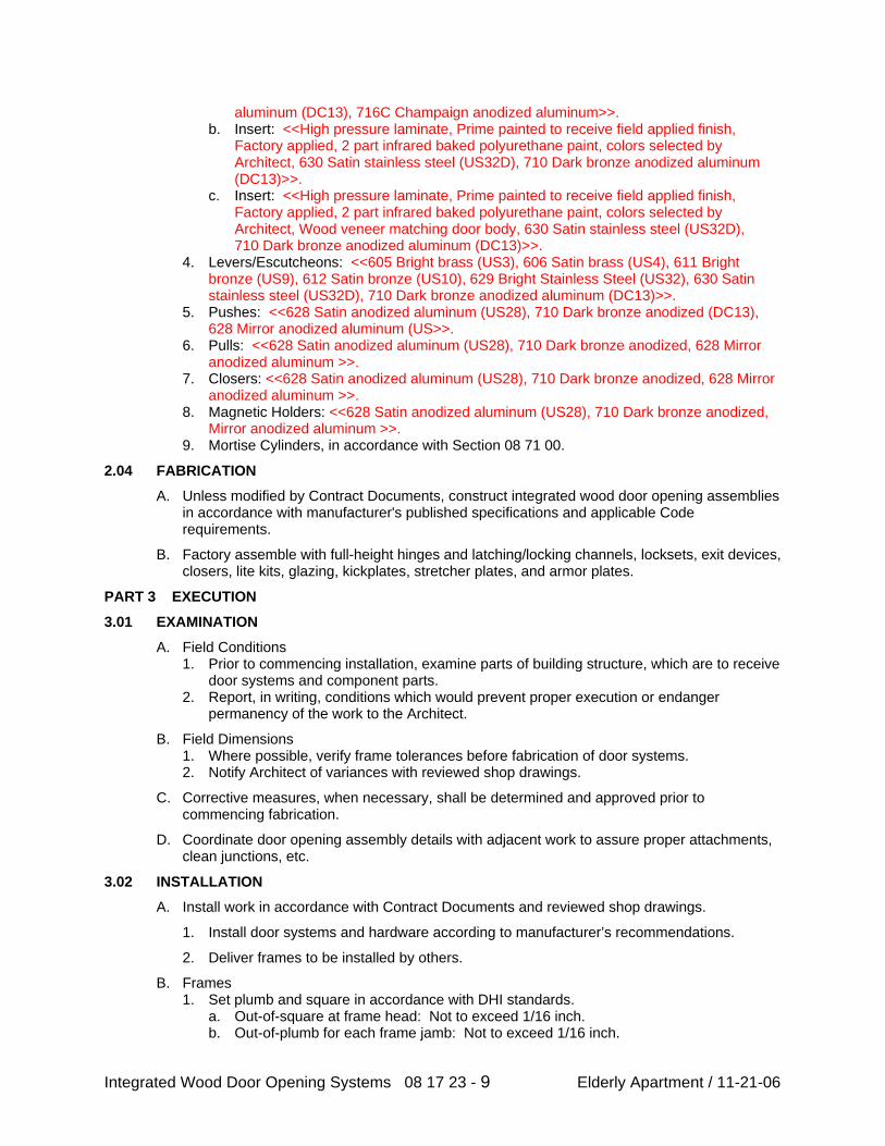
aluminum (DC13), 716C Champaign anodized aluminum>>. b. Insert: <<High pressure laminate, Prime painted to receive field applied finish,
Factory applied, 2 part infrared baked polyurethane paint, colors selected by Architect, 630 Satin stainless steel (US32D), 710 Dark bronze anodized aluminum (DC13)>>.
c. Insert: <<High pressure laminate, Prime painted to receive field applied finish, Factory applied, 2 part infrared baked polyurethane paint, colors selected by Architect, Wood veneer matching door body, 630 Satin stainless steel (US32D), 710 Dark bronze anodized aluminum (DC13)>>.
4. Levers/Escutcheons: <<605 Bright brass (US3), 606 Satin brass (US4), 611 Bright bronze (US9), 612 Satin bronze (US10), 629 Bright Stainless Steel (US32), 630 Satin stainless steel (US32D), 710 Dark bronze anodized aluminum (DC13)>>.
5. Pushes: <<628 Satin anodized aluminum (US28), 710 Dark bronze anodized (DC13), 628 Mirror anodized aluminum (US>>.
6. Pulls: <<628 Satin anodized aluminum (US28), 710 Dark bronze anodized, 628 Mirror anodized aluminum >>.
7. Closers: <<628 Satin anodized aluminum (US28), 710 Dark bronze anodized, 628 Mirror anodized aluminum >>.
8. Magnetic Holders: <<628 Satin anodized aluminum (US28), 710 Dark bronze anodized, Mirror anodized aluminum >>.
9. Mortise Cylinders, in accordance with Section 08 71 00.
2.04 FABRICATION
A. Unless modified by Contract Documents, construct integrated wood door opening assemblies in accordance with manufacturer's published specifications and applicable Code requirements.
B. Factory assemble with full-height hinges and latching/locking channels, locksets, exit devices, closers, lite kits, glazing, kickplates, stretcher plates, and armor plates.
PART 3 EXECUTION
3.01 EXAMINATION
A. Field Conditions 1. Prior to commencing installation, examine parts of building structure, which are to receive
door systems and component parts. 2. Report, in writing, conditions which would prevent proper execution or endanger
permanency of the work to the Architect.
B. Field Dimensions 1. Where possible, verify frame tolerances before fabrication of door systems. 2. Notify Architect of variances with reviewed shop drawings.
C. Corrective measures, when necessary, shall be determined and approved prior to commencing fabrication.
D. Coordinate door opening assembly details with adjacent work to assure proper attachments, clean junctions, etc.
3.02 INSTALLATION
A. Install work in accordance with Contract Documents and reviewed shop drawings.
1. Install door systems and hardware according to manufacturer’s recommendations.
2. Deliver frames to be installed by others.
B. Frames 1. Set plumb and square in accordance with DHI standards.
a. Out-of-square at frame head: Not to exceed 1/16 inch. b. Out-of-plumb for each frame jamb: Not to exceed 1/16 inch.
Integrated Wood Door Opening Systems 08 17 23 - 9 Elderly Apartment / 11-21-06
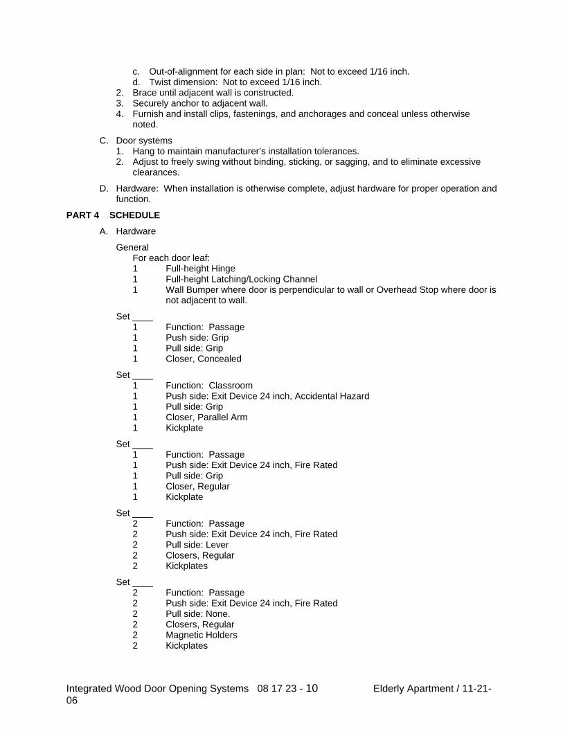
c. Out-of-alignment for each side in plan: Not to exceed 1/16 inch. d. Twist dimension: Not to exceed 1/16 inch.
2. Brace until adjacent wall is constructed. 3. Securely anchor to adjacent wall. 4. Furnish and install clips, fastenings, and anchorages and conceal unless otherwise
noted.
C. Door systems 1. Hang to maintain manufacturer’s installation tolerances. 2. Adjust to freely swing without binding, sticking, or sagging, and to eliminate excessive
clearances.
D. Hardware: When installation is otherwise complete, adjust hardware for proper operation and function.
PART 4 SCHEDULE
A. Hardware
General For each door leaf: 1 Full-height Hinge 1 Full-height Latching/Locking Channel 1 Wall Bumper where door is perpendicular to wall or Overhead Stop where door is
not adjacent to wall.
Set ____ 1 Function: Passage 1 Push side: Grip 1 Pull side: Grip 1 Closer, Concealed
Set ____ 1 Function: Classroom 1 Push side: Exit Device 24 inch, Accidental Hazard 1 Pull side: Grip 1 Closer, Parallel Arm 1 Kickplate
Set ____ 1 Function: Passage 1 Push side: Exit Device 24 inch, Fire Rated 1 Pull side: Grip 1 Closer, Regular 1 Kickplate
Set ____ 2 Function: Passage 2 Push side: Exit Device 24 inch, Fire Rated 2 Pull side: Lever 2 Closers, Regular 2 Kickplates
Set ____ 2 Function: Passage 2 Push side: Exit Device 24 inch, Fire Rated 2 Pull side: None. 2 Closers, Regular 2 Magnetic Holders 2 Kickplates
Integrated Wood Door Opening Systems 08 17 23 - 10 Elderly Apartment / 11-21-06
Set ____ 1 Function: Passage 1 Push side: Exit Device 24 inch, Fire Rated 1 Pull side: Lever. 1 Closer, Regular 1 Magnetic Holder 1 Kickplate
Set ____ 2 Function: Passage 2 Push side: Exit Device 24 inch, Fire Rated 2 Pull side: Lever. 2 Closers, Regular 2 Magnetic Holders 2 Kickplates
END OF SECTION
Integrated Wood Door Opening Systems 08 17 23 - 11 Elderly Apartment / 11-21-06
Elderly Apartment / 11-21-06 08 17 23 - 1 Prehung Wood Doors
SECTION 08 17 23
PREHUNG WOOD DOORS
PART 1 GENERAL
1.01 SECTION INCLUDES
A. Prehung wood doors.
1.02 RELATED SECTIONS
A. Section 08 17 23 – Prehung Metal Doors.
B. Section 08 20 0 – Wood Doors.
C. Section 08 71 0 – Door Hardware.
D. Section 08 80 0- Glazing: Glass for vision panels.
1.03 REFERENCES
A. AWI Architectural Wood Work Quality Standards, Architectural Woodwork Institute.
B. WDMA Window and Door Manufacturers Association Industry Standard I.S. I-A, Architectural Wood Flush Doors.
1.04 DELIVERY, STORAGE, AND HANDLING
A. Comply with Section 01600.
1. Protect during transit, storage, and handling to prevent damage, soiling and deterioration.
2. Comply with manufacturer’s instructions and AWI requirements for care and handling of doors.
3. Deliver to site after wet construction operations are completed and dry and building has reached prevailing relative humidity.
4. Deliver components in manufacturer’s original unopened protective covering or container, clearly marked with manufacturer’s name, brand name, and identifying door opening number on covering.
B. Storage: Store in clean, dry, well ventilated area protected from sun light.
1. Avoid extreme heat, cold, dryness or humidity.
2. Store flat over level surface above floor on wood blocking.
Elderly Apartment / 11-21-06 08 17 23 - 2 Prehung Wood Doors
3. Under bottom door and over top of stack; furnish plywood or corrugated cardboard for protection.
C. Handling: Do not drag doors across one another or across other surfaces.
1.05 ENVIRONMENTAL REQUIREMENTS
A. Comply with manufacturers written requirements under which products can be installed.
1. Condition doors to average prevailing humidity of not less than 25% and not greater than 55%, typically, in installation area.
PART 2 PRODUCTS
2.01 PREHUNG WOOD DOOR MANUFACTURERS
A. Acceptable Five Ply Door Manufacturers
1. Woodharbor Doors and Cabinetry, Mason City, IA
2. Karona, Caledonia, MI
3. Buell Door Company, Dallas, TX
2.02 MATERIALS
A. Composite core, lumber core, or solid wood jambs: ANSI A208.1, Grade I-LD-2.
B. Wood Face Veneer: AWI Quality Standard, AWI Grade A.
C. Wood Species: As selected by architect.
D. Profiles: As selected by architect.
2.03 WOOD PREHUNG DOORS
A. General: AWI Section 1300
1. Door Thickness: 1 3/8”
2. Stills: 4 ¾” Wide
3. Top Rail: 4 3/ 4” Wide
4. Bottom Rail: 8” Wide
5. Raised Panel: ¾” Solid Wood or MDF
6. Flat Panel: 3/8” Composite-Core Plywood or MDF
Elderly Apartment / 11-21-06 08 17 23 - 3 Prehung Wood Doors
B. Fire Rated doors: AWI FD-5 ME, Premium.
2.04 ACCESSORIES
A. Vision Panel Molding.
1. Fire Rated Doors.
2.05 FINISHINGS
A. Comply with AWI Section 1500 for types of factory applied finish systems indicated.
B. Provide transparent factory applied finishes at locations scheduled.
C. AWI Section TR-4 Conversion Varnish: AWI Premium Grade.
1. Stain: to match sample.
2. Degree of sheen: semi-gloss.
D. Finish edge stiles to match door face finish.
E. Find hardwood molding to match face veneers.
PART 3 EXECUTION
3.01 INSTALLATION
A. Install in accordance with Section 01600, AWI Section 01700, approved shop drawings and manufacturer’s written instructions.
3.02 ADJUSTING
A. After installation of hardware, adjust and check each door to ensure proper operation and function.
3.03 CLEANING AND PROTECTION
A. Protect finish work in accordance with Section 01500.
B. Cleaning: Comply with Section 01740. Clean as recommended by manufacturer. Do not use materials or methods which may damage finish.
END OF SECTION
Ederly Apartment /4-28-06 08 50 20 Window
SECTION 08 50 20
ALUMINUM WINDOWS PART 1 GENERAL 1.01 RELATED WORK SPECIFIED ELSEWHERE A. Joint Sealers: Section 07900. B. Glass and Glazing: Section 08800. 1.02 REFERENCES A. Voluntary Specifications for Aluminum Prime Windows & Sliding Glass Doors,
ANSI/AAMA 101, sponsored and published by American Architectural Manufacturers Association.
1.03 SUBMITTALS A. Shop Drawings: Show fabrication details and connections to adjacent
construction. B. Product Data: Catalog sheets, specifications, and installation instructions for
each type window unit. C. Samples: 1. One window unit of each type, with insect screen, and hardware. 1. Corner section of frame, sash, and insect screen. 2. Color Samples: Manufacturer's standard color finishes. 1.04 QUALITY ASSURANCE A. Certification: Each window unit shall bear the AAMA Certification label. 1.05 DELIVERY, STORAGE, AND HANDLING A. Deliver windows in protective containers, marked with identification for window
location. B. Store and handle windows in a manner that will not cause damage to the finish. PART 2 PRODUCTS 2.01 ALUMINUM WINDOW TYPES/GRADE/PERFORMANCE CLASS A. Comply with the ANSI/AAMA 101 requirements for the following window
designation(s): 1. A-R15 Awning Window, Residential Grade. 2. A-C20 Awning Window, Commercial Grade. 3. C-R15 Casement Window, Residential Grade.
Ederly Apartment /4-28-06 08 50 20 Window
4. C-C20 Casement Window, Commercial Grade. 5. C-HC40 Casement Window, Heavy Commercial Grade. 6. DH-R15 Double Hung Window, Residential Grade. 7. DH-DW-R15 Double Hung Dual Window, Residential Grade. 8. DH-C20 Double Hung Window, Commercial Grade. 9. DH-DW-C20 Double Hung Dual Window, Commercial Grade. 10. DH-HC40 Double Hung Window, Heavy Commercial Grade. 11. HS-R15 Horizontal Sliding Window, Residential Grade. 12. HS-DW-R15 Horizontal Sliding Dual Window, Residential
Grade. 13. HS-C20 Horizontal Sliding Window, Commercial Grade. 14. HS-DW-C20 Horizontal Sliding Dual Window, Commercial
Grade. 15. HS-HC40 Horizontal Sliding Window, Heavy Commercial
Grade. 16. P-R15 Projected Window, Residential Grade. 17. P-C20 Projected Window, Commercial Grade. 18. P-HC40 Projected Window, Heavy Commercial Grade. 19. TH-C20 Top Hinged Window, Commercial Grade. 20. TH-HC40 Top Hinged Window, Heavy Commercial Grade. 21. VP-C20 Vertically Pivoted Window, Commercial Grade. 22. VP-HC40 Vertically Pivoted Window, Heavy Commercial
Grade. 23. F-R15 Fixed Window, Residential Grade. 24. F-DW-R15 Fixed Dual Window, Residential Grade. 25. F-C20 Fixed Window, Commercial Grade. 26. F-DW-C20 Fixed Dual Window, Commercial Grade. 27. F-HC40 Fixed Window, Heavy Commercial Grade. 2.02 MATERIALS A. Frame and Sash Members: Extruded Aluminum, 6063 alloy T5 temper. B. Fasteners: Aluminum or Stainless steel. 1. Exposed Fasteners: Phillips flat-head screws. Match the finish
of the member being fastened. 1. Exposed Fasteners: Flat spanner head screws. Match the finish
of the member being fastened. C. Compression Weatherstripping: 1. Neoprene Gaskets: ASTM D 2000. 2. PVC Gaskets: ASTM D 2287. 3. Expanded Neoprene Gaskets: ASTM C 509, Grade 4. D. Sliding Weatherstripping: 1. Woven Pile: AAMA 701.2. E. Thermal Break: Provide manufacturer's standard continuous thermal barrier. F. Insect Screens: Manufacturer's standard removable unit for each operable sash,
designed not to interfere with sash operation. 1. Frame: Extruded or formed aluminum 0.040 inch min wall
thickness, mitred or coped joints, concealed mechanical fasteners.
Ederly Apartment /4-28-06 08 50 20 Window
2. Retainer Spline: Vinyl. 3. Screen Mesh: a. Aluminum mesh, 18 x 16, .011 inch wire
diameter, black or charcoal color finish; FS RR-W-365, Type VII. b. Stainless steel mesh, 18 x 18, 0.009 inch wire
diameter; AISI Type 316; FS RR-W-365, Type VI. c. Glass fiber mesh, plastic coated, 18 x 14, 0.013
inch filament diameter; FS L-S-125, Type II, Class 2. G. Bituminous Coating: Cold-applied asphalt mastic complying with SSPC-PAINT
12, compounded for 30-mil thickness per coat. 2.03 FINISHES A. Prepare the aluminum surfaces for finishing in accordance with the Aluminum
Association recommendations and standards. B. Finish all exposed aluminum surfaces. Process all components of each assembly
simultaneously to attain uniform color. C. Finish: Natural Anodized, NAAMM AA-M21C22A41, (minimum thickness 0.7
mils), natural aluminum color. D. Finish: Color Anodized, NAAMM AA-M21C22A42, heavy colored, (minimum
thickness 0.7 mils), integral color anodized finish. 1. Color: E. Finish: Color Anodized, NAAMM AA-M21C22A32 medium colored,
(minimum thickness 0.4 mils) integral color anodized finish. 1. Color: F. Finish: Manufacturer's standard factory applied baked enamel finish. 1. Color: 2.04 ACCESSORIES A. Poles: Manufacturer's standard; one pole for each room or space where a sash
locking rail is over 6'-6" above the floor. PART 3 EXECUTION 3.01 EXAMINATION A. Verification of Conditions: Examine surfaces to receive aluminum windows for
defects that will adversely affect the execution and quality of the Work. Do not proceed until unsatisfactory conditions are corrected.
3.02 INSTALLATION A. Install the Work of this Section in accordance with the manufacturer's printed
instructions, except as shown or specified otherwise.
Ederly Apartment /4-28-06 08 50 20 Window
B. Paint aluminum surfaces in contact with masonry or incompatible metals with bituminous coating.
C. Anchor window units securely in place, plumb, level, aligned, without warp of
frames or sash. 3.03 ADJUSTING A. Adjust operating sash and hardware for smooth operation and weathertight
closure. Lubricate hardware and other moving parts, except parts in contact with weatherstripping.
3.04 CLEANING A. Clean aluminum surfaces promptly after installation.
END OF SECTION
SECTION 08 71 00
DOOR HARDWARE
PART 1 GENERAL
1.01 SUMMARY
A. Section Includes:
1. Butt hinges.
2. Geared continuous hinges.
3. Locksets and Latchsets [Mechanical] [Electromechanical].
a. Mortise type.
4. Knob cylinder locksets.
5. Lever cylinder locksets.
6. Closers.
7. Exit devices.
Specifier Note: Revise paragraph below to suit project requirements. Add section
numbers and titles per CSI MasterFormat and specifier’s practice.
B. Related Sections:
1. Section [01 33 00 - Submittal Procedures] [______].
2. Section [01 45 00 - Quality Control] [______].
3. Section [01 78 00 - Closeout Submittals] [______].
4. Section [08 11 00 - Metal Doors and Frames] [______].
5. Section [08 11 16 Aluminum Doors and Frames] [______].
6. Section [08 14 16 - Flush Wood Doors] [______].
Specifier Note: Article below may be omitted when specifying manufacturer.s
proprietary products and recommended installation. Retain Reference Article when
specifying products and installation by an industry reference standard. If retained, list
standard(s) referenced in this section. Indicate issuing authority name, acronym, standard
designation and title. Establish policy for indicating edition date of standard referenced.
Conditions of the Contract or Division 01 References Section may establish the edition
date of standards. This article does not require compliance with standard, but is merely a
listing of references used. Article below should list only those industry standards
Elderly Apartment / 11-21-06 08 71 00 Door Hardware
referenced in this section. Retain only those reference standards to be used within the text
of this Section. Add and delete as required for specific project.
1.02 REFERENCES
A. American National Standards Institute/Builders Hardware Manufacturers
Association (ANSI/BHMA):
1. ANSI/BHMA A156.1 Butts & Hinges.
2. ANSI/BHMA A156.2 Bored and Preassembled Locks and Latches.
3. ANSI/BHMA A156.3 Exit Devices.
4. ANSI/BHMA A156.4 Door Controls - Closers.
5. ANSI/BHMA A156.13 Mortise Locks & Latches.
6. ANSI/BHMA A156.18 Materials & Finishes.
7. ANSI/BHMA A156.21 Thresholds.
8. ANSI/BHMA A156.22 Door Gasketing Systems.
9. ANSI/BHMA A156.26 Continuous Hinges.
B. American National Standards Institute (ANSI):
1. ANSI A117.1 Accessible and Usable Buildings and Facilities.
C. Underwriters Laboratories, Inc. (UL):
1. UL 10B Fire Tests of Door Assemblies.
2. UL 10C Positive Pressure Fire Tests of Door Assemblies.
3. UL 305 Panic Hardware.
4. UL 1034 Burglary-Resistant Electric Locking Mechanisms.
Specifier Note: Article below includes submittal of relevant data to be furnished by
Contractor before, during or after construction. Coordinate this article with Architect’s
and Contractor’s duties and responsibilities in Conditions of the Contract and Division 01
Submittal Procedures Section.
1.03 SUBMITTALS
A. General: Submit listed submittals per Conditions of the Contract and
Division 01 Submittal Procedures.
B. Product Data: Submit manufacturer’s complete product literature for
specified hardware items, detailed installation diagrams and instructions,
including:
Elderly Apartment / 11-21-06 08 71 00 Door Hardware
1. Preparation instructions and recommendations.
2. Storage and handling requirements and recommendations.
3. Installation methods.
C. Samples:
Specifier Note: Describe specific types and quantities of samples required to determine
style, finish or other characteristics.
1. Submit [One] [______] sample[s] of each type of threshold or
accessory.
2. Identify each sample by label indicating applicable specification
paragraph number, brand name and number, finish and hardware package
number.
3. After approval, samples will be returned for incorporation into work.
D. Shop Drawings: Submit shop drawings detailing installation procedures,
including layout, dimensions and placement of hardware.
E. Quality Assurance:
1. Certificates: Product certificates signed by manufacturer certifying
materials comply with specified performance characteristics and criteria
and physical requirements.
2. Manufacturer’s Instructions: Manufacturer’s installation instructions.
Specifier Note: Coordinate paragraph below with Part 3 Field Quality Requirements
Article. Retain or delete as applicable.
F. Closeout Submittals: Submit the following:
1. Warranty: Manufacturer’s standard warranty document executed by
authorized company official. Manufacturer’s warranty is in addition to,
and not a limitation of, other rights Owner may have under Contract
Documents.
2. Operation and Maintenance Data: Operation and maintenance data for
installed products per Division 01 Closeout Submittals (Maintenance Data
and Operation Data) Section. Include methods for maintaining installed
products and
Elderly Apartment / 11-21-06 08 71 00 Door Hardware
precautions against cleaning materials and methods detrimental to finishes
and performance.
1.04 QUALITY ASSURANCE
A. Qualifications: Installer experienced in performing work of this section
who has specialized in installation of work similar to that required for this
project.
B. Hardware Supplier: Company specializing in the supply of door hardware,
approved by manufacturer with [Specify years.] years documented
experience and an Architectural Hardware Consultant (AHC) to properly
handle, detail and service hardware in a satisfactory manner.
Specifier Note: Paragraph below should list obligations for compliance with specific code
requirements particular to this section. General statements to comply with a particular
code are typically addressed in Conditions of the Contract and Division 01 Regulatory
Requirements Section. Repetitive statements should be avoided.
C. Preinstallation Meetings: Conduct preinstallation meeting to verify project
requirements, manufacturer’s installation instructions and manufacturer’s
warranty requirements. Comply with Division 01 Project Management and
Coordination (Project Meetings).
1.05 DELIVERY, STORAGE & HANDLING
A. General: Comply with Division 01 Product Requirements.
B. Ordering: Comply with manufacturer’s ordering instructions and lead time
requirements to avoid construction delays.
C. Delivery, Storage and Protection:
1. Deliver, store and handle per Section [01 61 00 - Common Product
Requirements].
2. Deliver, store and handle materials per manufacturer’s written
instructions.
3. Deliver in original packaging with labels and identification intact.
4. Ship hardware items in lots coordinated with openings, as numbered in
door schedule.
Elderly Apartment / 11-21-06 08 71 00 Door Hardware
5. Inspect hardware items upon delivery to ensure that specified products
have been received.
6. Store hardware items in secure dry location, protected from weather
until ready for installation.
D. Waste Management and Disposal:
Specifier Note: ENVIRONMENT: The disposal of packaging waste into landfill site
demonstrates an inefficient use of natural resources and consumes valuable landfill space.
1. Separate waste materials for [Reuse] [And] [Recycling] [_____] per
Section [01 74 19 - Construction Waste Management and Disposal]
[______].
2. Remove from site and dispose of packaging materials at appropriate
recycling facilities.
3. Collect and separate for disposal [Paper] [Plastic] [Polystyrene]
[Corrugated cardboard] packaging material [In appropriate onsite bins]
[_____] for recycling.
1.06 PROJECT CONDITIONS
A. Maintain environmental conditions (temperature, humidity and
ventilation) within limits recommended by manufacturer for optimum
results. Do not install products under environmental conditions outside
manufacturer’s absolute limits.
Specifier Note: Coordinate article below with Conditions of the Contract and with
Division 01 Closeout Submittals (Warranty).
1.07 WARRANTY
A. Project Warranty: Refer to Conditions of the Contract for project warranty
provisions.
B. Manufacturer’s Warranty: Submit, for Owner’s acceptance,
manufacturer’s standard warranty document executed by authorized
company official. Manufacturer’s warranty is in addition to, and not a
limitation of, other rights Owner may have under Contract Documents.
Manufacturer’s standard warranty: One calendar year from date of
delivery to Project.
Elderly Apartment / 11-21-06 08 71 00 Door Hardware
1.08 EXTRA MATERIALS
A. Deliver to Owner extra materials from same production run as products
installed. Package products with protective covering
and identify with descriptive labels. Comply with Division 01 Closeout
Submittals (Maintenance Materials) Section.
Specifier Note: Revise Paragraph below specifying size and percentage as required for
project.
1. Quantity: Furnish quantity of full-size units equal to 5% of amount
installed.
a. Provide [10] [__] extra interchangeable cores for each [Master]
keyed group.
2. Special Tools: Provide special wrenches and tools applicable to each
different or special hardware component.
3. Maintenance Tools: Provide maintenance tools and accessories supplied
by hardware component manufacturer.
4. Delivery, Storage and Protection: Comply with Owner’s requirements
for delivery, storage and protection of extra materials.
PART 2 PRODUCTS
Specifier Note: Retain article below for proprietary method specification. Add product
attributes, performance characteristics, material standards and descriptions as applicable.
Use of such phrases as .or equal. or .or approved equal. or similar phrases may cause
ambiguity in specifications. Such phrases require verification (procedural, legal and
regulatory) and assignment of responsibility for determining .or equal. products.
2.01 DOOR HARDWARE
A. Manufacturer: Stanley Security Solutions, Inc.
1. Contact: 6161 E 75th St., Indianapolis, IN 46250-2701; Telephone:
(317) 849-2250; Fax: (317) 806-3276; website:
www.stanleysecuritysolutions.com.
B. Proprietary Products/Systems: Stanley Security Solutions door hardware.
2.02 HINGES
Elderly Apartment / 11-21-06 08 71 00 Door Hardware
A. Butt Hinges: To ANSI/BHMA A156.1, [Two] [Three] [Five] [______]
knuckle, flush concealed bearings, non-handed, material [Steel] [Brass]
[Stainless steel] [______], finish to ANSI/BHMA A156.18, BHMA
[______], [______].
Specifier Note: Only steel hinges can be used on fire-rated openings.
1. Cold headed, drawn stock steel pin.
2. Template screw hole locations.
3. Permanently lubricated non-detachable hardened chrome alloy vertical-
thrust ball-bearings, 2 minimum.
4. Easily seated, non-rising pins.
5. Sufficient size to allow 180 degree swing of door.
B. Geared Continuous Hinges: To ANSI A156.26 Grade 1, UL10B listed,
non-handed, anti-spinning through fastener, pins [______], [Fire pins for
3-hour fire ratings] [______].
2.03 LOCKSETS & LATCHSETS [MECHANICAL] [ELECTROMECHANICAL]
A. Mortise Type:
1. Locksets and Latchsets: To ANSI A156.13, [Series 1000, Operational
Grade 1] [Security Grade 2] UL listed.
2. Mortise lock to offer multi-function case with ability to be field
configured to ANSI function[s] [______] [______].
3. Heavy duty mortise type with 1-piece 3/4 inch (19.1 mm) throw
latchbolt, made with self-lubricating stainless steel, self-aligning, through-
bolted trim, ability to change handing without opening case.
4. Deadbolt and latchbolt extension into lock case minimum of 3/8 inch
(9.5 mm) when fully extended.
5. Handles: [Knob] [Lever] type, [Both sides] [______].
6. Locksets with 7-pin [______], interchangeable core cylinders; with
[Restricted] [Patented] [Mortise cylinders with concealed internal set
screw accessible only by removing core from cylinder body].
7. Locksets with tactile, abrasive or knurled notes or levers for
identification of hazardous areas.
Elderly Apartment / 11-21-06 08 71 00 Door Hardware
8. Lever Handles: To ANSI A117.1, solid forged or cast construction.
9. Spindle: Design when forced will twist first, then break, preventing
forced entry.
10. Knobs and Levers: Operate with roller bearing spindle hub
mechanism.
11. Permanent core face same finish as lockset finish.
12. Cylinder Retaining Screw, Auxiliary Latch and Strike: [Non-handed]
[______].
13. Locking toggle indication on door face to show mortise lock is locked
or unlocked.
14. Cover and armored front to interlock at latch, preventing cover from
spreading or bowing.
15. Acceptable Material: Best Series [35HW] [45H] [______].
B. Knob Cylinder Locksets:
1. Locksets and Latchsets: To ANSI A156.2, Series 4000, Grade 1, UL
listed, extra heavy-duty cylindrical type.
2. Backset 2 3/4 inches (70 mm).
3. Latchbolt throw 9/16 inch (14.3 mm).
4. 7 Pin Interchangeable Core: [Restricted] [Patented] [______] keyway.
a. Acceptable Material: Best Series [____].
5. Knobs: Brass or bronze material, minimum of 0.100 inches (2.5 mm)
thick at thinnest point of knob wall.
6. Locksets with tactile, abrasive or knurled notes or levers for
identification of hazardous areas.
7. Shank: Solid with no opening for access to keyed knob keeper.
8. Keyed Knob:
a. Removable only after core is removed, by authorized control
key, to allow access to knob keeper.
b. Protected by breakaway mechanism to prevent forced entry.
c. Capable of changing hand before and after installation by
rotating knob face.
Elderly Apartment / 11-21-06 08 71 00 Door Hardware
9. Permanent Core Face: Same finish as lockset finish.
10. Acceptable Material: Best Access Systems Series [8K], trim [______].
C. Lever Cylinder Locksets:
1. Locksets and Latchsets: To ANSI A156.2, Series 4000, Grade 1, UL
listed, extra heavy-duty cylindrical type.
2. Backset 2 3/4 inches (70 mm).
3. Interchangeable Core: [Restricted keyway] [Patented] [Standard]
[______].
4. Locksets to have anti-rotational studs that are through-bolted.
5. Keyed lever with no exposed keeper hole.
6. Each lever to have independent spring mechanism designed to control
lever only.
7. Outside lever sleeve seamless, 1-piece construction, hardened steel
alloy.
8. Keyed Lever: Removable only after core is removed, by authorized
control key, to allow access to knob keeper.
9. Hub, side plate, anti-rotational studs 1-piece casting with shrouded
locking lug.
10. Permanent core face same finish as lockset finish.
Specifier Note: Use the following article for electromechanical lever locksets and
latchsets.
11. Lock solenoid, door status sensor and Request-to-Exit sensor included
within mortise case.
12. Acceptable Material: Best Access Systems Series [9K] [9KW], trim
[______].
2.04 DOOR CLOSERS
A. Closers: To ANSI A156.4 Grade 1, non-handed, sizes 1 - 6, with
adjustable latching, closing and backcheck using 3 separate non-critical V-
slot hydraulic control valves.
1. ANSI A156.4 PT4-C 50%.
2. Conforms to ANSI A117.1.
Elderly Apartment / 11-21-06 08 71 00 Door Hardware
3. UL10C listed.
4. Opening and closing cycle controlled hydraulically.
5. Hydraulic fluid viscosity range of 0 - 100 degrees F (-18 - 38 degreesC).
6. Extra-duty arms and knuckle with forged or cast main arm, forearms
and mounting shoes.
7. Full rack-and-pinion operation.
8. Covers: High impact, self-extinguishing.
9. Closer Body: R14 cast silicon aluminum.
10. Piston diameter minimum of 1 1/2 inches (38 mm).
11. Acceptable Material: Stanley door closer model number [______].
2.05 EXIT DEVICES
A. Exit Devices: To ANSI A156.3 Grade 1, stainless steel, with stainless steel
deadlocking latchbolts and complete with:
1. Touch-pad device with pad covering half of door width, minimum, with
sound reduction dampening feature of touchpad during depression and
extension.
2. Lock stile chassis of investment cast steel.
3. UL 305 listed for panic hardware.
4. UL 10C listed for fire (as specified).
5. Adjustable, investment cast stainless steel strikes.
6. 14 gauge (0.075 mm thick) device housing exposed surfaces, 16 gauge
(0.060 mm thick) stainless steel.
7. Outside Trim: Cast or forged brass/bronze, full escutcheon, through-
bolted to chassis.
8. Field convertible handing and function.
9. Vandal resistant lever trim.
10. Metal end caps secured to bracket interlocking with devices channel
base and hinge side filler.
11. Key removable mullions by device manufacturer.
12. Device to provide 1/4 inch (6.4 mm) between door face and housing.
13. Acceptable Material: Precision Exit Devices catalog number [______].
Elderly Apartment / 11-21-06 08 71 00 Door Hardware
Specifier Note: Use the following article to specify heavy duty high security exit devices.
These devices can be specified with, or without, an internal alarm; wired directly to a
building alarm system. No outside trim is available, and these devices are for egress only.
B. Security Exit Devices: To ANSI A156.3 Grade 1, heavy duty high security
exit devices with UL 305 listed for panic
hardware, UL 10B listed for fire (as specified) and UL 1034 forced entry
tested, complete with:
1. Touch pad operated.
2. 2 point locking, 1 bolt into hinge jamb/1 bolt into strike jamb with 2
inch (51 mm) engagement each side.
3. Device to span entire door and frame, non-handed, factory
preassembled, locking bar to show security visually with automatic re-
locking.
4. 1 1/4 inch (32 mm) square telescoping steel bolts with roller bearing
tips.
5. 3/8 inch (9.5 mm) grade 5 hardened through-bolt mounting with tamper
resistant outside washers and internal support
sleeve.
6. [Alarmed] [Non-alarmed] components contained within device and
activated by mortise cylinder.
7. Direct wiring to external alarm.
8. Alarm: [92db 9V] [______].
9. Acceptable Material: Sargent and Greenleaf High Security Exit Devices
model number [______].
2.06 KEYS & KEYING
A. Cylinders: 7-pin, interchangeable core and keyed into a [New] [Existing]
factory registered Grand Masterkey System with a [Standard] [Restricted]
[Patented] keyway.
1. Acceptable Material: Cylinders as manufactured by Best Access
Systems.
Elderly Apartment / 11-21-06 08 71 00 Door Hardware
B. Provide construction cores and keys during construction period.
Construction control and operating keys and cores are not part of
permanent keying system or furnished on same keyway (or key section) as
permanent keying system.
C. Permanent Keys and Cores: Prepare permanent cores and keys in
accordance with keying schedule. [Stamp with applicable key mark for
identification.] [Do not stamp.] [______].
D. Provide Grand Masterkeys, Masterkeys and other Security Keys.
E. Furnish keys in the following quantities:
1. [4] [______] each Grand Masterkeys.
2. [4] [______] each Masterkeys per set.
3. [2] [______] each Change keys each keyed core.
4. [6] [______] each Construction masterkeys.
5. [2] [______] each Control keys.
6. Install permanent cores in locksets.
F. Return construction cores to [{Best} factory representative] [Hardware
manufacturer’s representative].
Specifier Note: Edit Paragraph below to suit project requirements. If substitutions are
permitted, edit text below. Add text to refer to Division 01 Project Requirements (Product
Substitution Procedures) Section.
2.07 PRODUCT SUBSTITUTIONS
A. Substitutions: No substitutions permitted.
PART 3 EXECUTION
3.01 MANUFACTURER.S INSTRUCTIONS
Specifier Note: Article below is an addition to the CSI SectionFormat and a supplement
to MANU-SPEC. Revise article below to suit project requirements and specifier’s
practice.
A. Compliance: Comply with manufacturer’s written data, including product
technical bulletins, product catalog installation
instructions and product carton installation instructions.
Elderly Apartment / 11-21-06 08 71 00 Door Hardware
B. Furnish metal door and frame manufacturers with complete instructions
and templates for preparation of their work to receive hinges.
1. Furnish manufacturers. instructions for proper installation of each hinge
component.
3.02 EXAMINATION
A. Site Verification of Conditions: Verify that substrate conditions are
acceptable for product installation per manufacturer’s instructions.
3.03 INSTALLATION
Specifier Note: Note there are special hinge mounting height requirements for elementary
schools and accessible doors.
Specifier Note: Check frame types for hinge mounting locations. Some frame
manufacturers have predetermined mounting heights for hinges.
A. Install hinges to standard hardware location dimensions per
manufacturer’s instructions.
B. Use only manufacturer’s supplied fasteners. Failure to comply may void
manufacturer’s warranties and applicable licensed labels. Use of .quick.
type fasteners, unless specifically supplied by manufacturer, is
unacceptable.
3.04 ADJUSTING
A. Adjust door hardware for optimum, smooth operating condition.
1. Lubricate hinges and other moving hardware where directed by
manufacturer.
2. Adjust door hinges to provide tight fit at contact points with frames.
B. Adjust weatherstrip and seals to allow for unobstructed door operation.
C. Adjust thresholds and accessories to allow for unobstructed door
operation.
D. Adjust door closers to manufacturer’s instructions and as follows:
1. Adjust closing time based on expected usage.
2. Adjust latch speed so door completely closes and latches.
3. Adjust backcheck accordingly to prevent excessive opening speed.
4. Adjust delay action accordingly to obtain desired delay time.
Elderly Apartment / 11-21-06 08 71 00 Door Hardware
5. Use 5/32 inch (4 mm) hex wrench to adjust door closer for
corresponding door size.
6. Lubricate where directed by manufacturer.
E. Adjust locking components for optimum, smooth operating condition.
1. Lubricate where directed by manufacturer.
F. Adjust installed pull plates and pushplates and protection items for proper
function.
3.05 PROTECTION
A. Protect installed products until completion of project.
B. Touch up, repair or replace damaged products before Substantial
Completion.
3.06 FIELD QUALITY CONTROL
A. Site Tests, Inspection: Inspect completed assembly for proper locknut
screw-in depth, after installation and prior to final acceptance. Report
component damage to [Supplier] [______].
3.07 CLEANUP
A. Proceed in accordance with Section [01 74 00 - Cleaning and Waste
Management] [______].
B. Clean hinges with damp rag and approved nonabrasive cleaner, and polish
hinges per manufacturer’s instructions.
C. Remove protective material from hinges where present.
D. Upon completion and verification of performance of installation, remove
surplus materials, excess materials, rubbish, tools and equipment.
END OF SECTION
Elderly Apartment / 11-21-06 08 71 00 Door Hardware
Elderly Apartment / 4-28-06 09 21 16 – 1 Gypsum Board Assemblies
SECTION 09 21 16
GYPSUM BOARD ASSEMBLIES ON METAL FRAMING
PART 1 GENERAL 1.1 SUMMARY
A. Description of Work: Work of this section includes, but is not limited to, the following:
1. Gypsum board and accessories 2. Veneer plaster 3. Metal studs and furring 4. Metal shaftwall systems 5. Metal suspension systems 6. Sound-rated construction and accessories 7. Gypsum board finishing 8. Trim and accessories
1.2 RELATED WORK SPECIFIED ELSEWHERE
A. See Section 09310 CERAMIC TILE for tile facing on cement backer board.
B. See Section 09510 ACOUSTICAL CEILINGS for suspended acoustical ceilings.
C. See Section 09900 PAINTING AND FINISHING for gypsum board prime and finish
coats. 1.3 SUBMITTALS
A. Product Data: Submit manufacturer's specifications and installation instructions with
project conditions and materials clearly identified or detailed for each required system. 1.4 SYSTEM REQUIREMENTS
A. Performance Requirements: Fabricate and install systems as indicated but not less than
that required to comply with ASTM C754 under the following conditions: 1. Gypsum board partitions:
a. Standard systems: Maximum deflection of l/240 of partition height. b. Systems to receive water resistant gypsum board or backer board: Maximum
deflection of l/360 of partition height.
Elderly Apartment / 4-28-06 09 21 16 – 2 Gypsum Board Assemblies
2. Cavity shaftwall systems: Withstand minimum positive and negative pressure of 5 psf.
3. Interior suspended ceilings and soffits: Maximum deflection of l/360 of distance
between supports. 4. Exterior soffits: Withstand minimum positive and negative pressure of 20 psf with
maximum deflection of l/360 of distance between supports.
B. Fire Resistance Ratings: Where fire resistance classifications are indicated, provide materials and application procedures identical to those listed by UL or tested according to ASTM E119 for type of construction shown.
C. Acoustical Ratings: Where sound ratings are indicated, provide materials and
application procedures identical to those tested by manufacturer to achieve Sound Transmission Class (STC) scheduled or indicated in accordance with ASTM E90.
1.5 QUALITY ASSURANCE
A. Reference Standards:
1. Applicable requirements of ASTM C754 for installation of steel framing. 2. Install gypsum board in accordance with applicable requirements and
recommendations of Gypsum Association GA 216, "Recommended Specifications for the Application and Finishing of Gypsum Board", except for more stringent requirements of manufacturer.
3. Apply acoustical sealant in accordance with applicable requirements of ASTM
C919. 1.6 DELIVERY, STORAGE AND HANDLING
A. Delivery:
1. Deliver material to site promptly without undue exposure to weather. 2. Deliver in manufacturer's unopened containers or bundles, fully identified with
name, brand, type and grade.
B. Storage: 1. Store above ground in dry, ventilated space. 2. Protect materials from soiling, rusting and damage. 3. Store board to be directly applied to masonry walls at 70°F for 24 hours prior to
installation. 1.7 PROJECT CONDITIONS
A. Environmental Requirements:
1. Do not install gypsum board when ambient temperature is below 40°F.
Elderly Apartment / 4-28-06 09 21 16 – 3 Gypsum Board Assemblies
2. For adhesive attachment of gypsum board, and for finishing of gypsum board, maintain ambient temperature above 55°F from one week prior to attachment or joint treatment, and until joint treatment is complete and dry.
1.8 ALTERNATE CONSTRUCTION WASTE DISPOSAL
A. Reuse: 1. Separate clean waste drywall pieces from contaminants for landfilling or recycling.
Do not include vinyl-faced, mold-resistant or asphalt impregnated gypsum boards. Pulverize and apply to site soil in accordance to landscape specifications. Protect scrapes and pulverized material from moisture and contamination. Alternate to on-site soil amendment, work to supply local farming granular material for their use.
B. Recycle:
1. Separate clean waste drywall pieces from contaimants for landfilling or reuse.
Working with local waste hauler and local drywall manufacturer, provide proper storage of waste for pickup and return. Protect scrapes material from moisture and contamination.
PART 2 PRODUCTS 2.1 PRODUCTS AND MANUFACTURERS
A. Gypsum Board and Accessories: Listed products establish standard of quality and are
manufactured by United States Gypsum Company (USG), Chicago, IL.
B. Steel Framing and Furring: Company acceptable to installer.
C. Grid Suspension Assemblies: Listed products establish standard of quality and are manufactured by United States Gypsum Company (USG), Chicago, IL.
2.2 BOARD MATERIALS
A. Gypsum Board:
1. ASTM C36, regular type except where Type X fire-resistant type is indicated or
required to meet UL assembly types. 2. Edges: Tapered.
3. Thickness: 1/4 3/8 ½ 5/8 3/4 inch, unless otherwise indicated (½ 5/8 only for FIBEROCK Panels).
1. Where curved gypsum board construction is indicated, use 1/4 inch thick
flexible facing board. 4. Acceptable products:
a. Typical partitions and ceilings: Equivalent to Sheetrock Brand SW, Firecode or Firecode "C" Gypsum Panels by USG.
Elderly Apartment / 4-28-06 09 21 16 – 4 Gypsum Board Assemblies
b. OR depends on edge condition option: Equivalent to Sheetrock Brand Regular, Firecode or Firecode "C" Gypsum Panels by USG.
c. Acceptable product for fire-rated walls: Equivalent to Ultracode Core, 3/4
inch thick, by USG.
d. Acceptable product for curved walls: 1/4" Flexible Gypsum Panels.
e. Where foil-backed gypsum board is indicated: Equivalent to Sheetrock Brand SW Foil-Back, Firecode or Firecode "C" Gypsum Panels by USG. OR Sheetrock Brand Regular Foil-Back, Firecode or Firecode "C" Gypsum Panels by USG.
f. Use gypsum board and joint compound with little or no VOCs and
formaldehyde emissions. Gypsum board shall have a minimum of 5% Post-consumer and 20% Post-industrial (nation-wide average for company) as defined by FTC (Federal Trade Commision) by USG.
B. Ceiling Board:
1. ASTM C36, non-sag type. 2. Thickness: ½ inch. 3. Acceptable product: Equivalent to Interior Gypsum Ceiling Board by USG.
C. Water-Resistant Gypsum Board:
1. ASTM C630, regular type except where Type X fire-resistant type is indicated or required to meet UL assembly types.
2. Edges: Tapered. 3. Thickness: 5/8 ½ inch, unless otherwise indicated. 4. Acceptable products: Equivalent to Sheetrock Brand W/R, W/R Firecode "C" or
W/R Firecode Type X Gypsum Panels by USG.
D. Shaftwall: 1. Liner boards:
a. ASTM C442, Type SLX. b. Edges: Beveled. c. Thickness: 1 inch. d. Acceptable product: Equivalent to Gypsum Liner Panels by USG.
2. Face boards:
a. ASTM C36, Type X.
Elderly Apartment / 4-28-06 09 21 16 – 5 Gypsum Board Assemblies
b. Thickness: 5/8 ½ inch, unless otherwise indicated. c. Acceptable product: Equivalent to Sheetrock Brand Firecode "C" and
Firecode Gypsum Panels by USG.
E. Exterior Soffit Board: 1. Manufacturer's special weather and sag-resistant gypsum board manufactured
specifically for use in exterior soffit applications with indirect exposure to weather; complying with ASTM C931.
2. Edges: Eased and tapered. 3. Thickness: ½ 5/8 inch, except as otherwise indicated. 4. Acceptable product: Equivalent to Exterior Gypsum Ceiling Board (with Firecode
Core) by USG.
F. Cement Backer Board: 1. Aggregated Portland cement board with woven glass fiber mesh facing; complying
with ANSI A118.9. 2. Thickness: ½ 5/8 inch. 3. Acceptable product and manufacturer: Durock Cement Board by USG.
G. Veneer Plaster Partitions:
1. Base: Manufacturer's standard size gypsum base sheets in maximum available
lengths to minimize end-to-end joints; manufacturer's standard edge profile. a. Comply with ASTM C588. b. Regular type except where Type X fire-resistant type is indicated or required
to meet UL assembly types. c. Thickness: 5/8 ½ inch, unless otherwise indicated. d. Acceptable product: IMPERIAL Gypsum Base by USG.
2. Bonding agent: USG Plaster Bonder. 3. Plaster basecoat: Ready-mixed material, mill-prepared, high-strength gypsum
veneer plaster for two-coat application. Acceptable product: Equivalent to DIAMOND Basecoat by USG.
4. Plaster finish coat: Ready-mixed material.
a. Smooth trowel finish: Add water in accordance with manufacturer's
instructions. Acceptable product: Equivalent to IMPERIAL Finish by USG.
Elderly Apartment / 4-28-06 09 21 16 – 6 Gypsum Board Assemblies
b. Float finish: Add water and aggregate in accordance with manufacturer's instructions. Acceptable product: Equivalent to DIAMOND Interior Finish by USG.
2.3 METAL FRAMING AND FURRING MATERIALS
A. Metal Studs and Runners:
1. ASTM C645, "C" shaped, gauge:
a. Provide gauge as indicated for studs; runner gauge as recommended by stud
manufacturer. b. Provide 25 gauge studs, except as otherwise indicated or specified. Provide
heavier gauge if required. c. At door and borrowed light frames, provide (2) 25 gage minimum studs at
each jamb. Where wall is indicated or specified to be typically framed with 20 gauge studs, provide (2) 20 gauge studs at each jamb.
d. Provide 20 gauge studs at walls to receive cement backer board , and water
resistant gypsum board with ceramic tile facing. e. Provide runner gauge as recommended by stud manufacturer.
2. Depth of sections: As indicated. 3. Corrosion protection: G40 hot-dipped galvanized coating per ASTM A525.
B. Shaft Wall Supports:
1. Conform to ASTM A446, Grade A, with G40 hot-dipped galvanized coating per
ASTM A525. 2. Studs:
a. Shape: "CH", “J” or “E” or as standard with manufacturer. b. Gauge: As required to fulfill performance criteria, minimum 25 gauge.
Provide 20 gauge for jamb and lintel components. c. Size: As indicated. d. J runners: 24 gauge, size as required for coordination with studs. e. Jamb struts: 20 gauge with 3 inch back leg for use at elevator frames.
C. Metal Furring Channels:
1. Hat-shaped:
Elderly Apartment / 4-28-06 09 21 16 – 7 Gypsum Board Assemblies
a. ASTM C645, 7/8 inch high, 25 gauge, with G40 hot-dipped galvanized coating per ASTM A525.
b. Provide 20 gauge at furring to receive tile backer board. c. Acceptable products: DWC-25 for ½" and 5/8" gypsum board and DWC-20
by USG. 2. Z-shaped: ASTM C645, depths as indicated, 24 gauge minimum, with G40 hot-
dipped galvanized coating per ASTM A525. 3. Resilient: Manufacturer's standard type designed to reduce sound transmission; ½
inch deep, 25 gauge steel with G40 hot-dipped galvanized coating per ASTM A525.
2.4 CEILING AND SOFFIT SUPPORT MATERIALS
A. Hanger Anchorage Devices: Screws, clips, bolts or other devices compatible with
indicated structural anchorage for ceiling hangers and whose suitability has been proven through standard construction practices or by certified test data.
B. Powder-Actuated Fasteners in Concrete: Fabricated from corrosion-resistant materials,
with clips or other accessory devices for attaching hangers and with capability to sustain, without failure, a load equal to 10x calculated loads.
C. Post-tensioned Concrete Slabs:
1. For inserts placed in post-tensioned concrete work, maintain 3 inch clearance
between inserts and prestressing strands. 2. If insert is in conflict with strand, insert must be moved to avoid strand. Do not
move strands to avoid inserts.
D. Hangers: 1. Steel wire or rods, sizes to comply with requirements of ASTM C754 for ceiling or
soffit area and loads to be supported. 2. Wire: ASTM A 641, soft, Class 1 galvanized. 3. Rods and flats:
1. Mild steel components. 2. Finish: Galvanized or painted with rust-inhibitive paint for interior work;
galvanized for exterior work.
E. Framing System: 1. Main runners:
1. Cold-rolled, "C" shaped steel channels, 16 gauge minimum.
Elderly Apartment / 4-28-06 09 21 16 – 8 Gypsum Board Assemblies
2. Finish: Galvanized with G40 hot-dip galvanized coating per ASTM A525 for exterior work; galvanized or painted with rust-inhibitive paint for other interior work.
3. Form to required radius at curved ceilings.
2. Cross furring: Hat-shaped steel furring channels, ASTM C645, 7/8 inch high, 25
gauge, galvanized. 3. Furring anchorages: 16 gauge galvanized wire ties, manufacturer's standard
wire-type clips, bolts, nails or screws recommended by furring manufacturer and complying with ASTM C754.
4. Provide compression posts and other accessories as required to comply with
seismic requirements.
F. Proprietary Framing System: 1. Framing system for gypsum board panels consisting of cold-rolled steel members
conforming to ASTM C635, with exposed surfaces finished in manufacturer’s standard enamel paint finish.
2. Fire rating: 1 1-1/2 2 3 hour rating in accordance with UL assembly indicated. 3. Components: Main tees, furring cross channels, furring cross tees, and cross tees. 4. Accessories:
a. U-shaped channel molding. b. Galvanized carbon steel (12 ga.) hanger wire.
5. Acceptable product: Equivalent to Drywall Suspension System by USG.
2.5 ACCESSORIES
A. Metal Trim for Gypsum Board:
1. Conform to profile and dimensions indicated. 2. Material for interior work: Galvanized steel, 26 gauge minimum. 3. Corner beads: Equivalent to Dur-A-Bead No. 103 104 800 900 by USG. 4. Casing beads (edge beads): Equivalent to 200A 200B 401 402 P-1 701-B 801-A
801-B by USG. 5. Control joints:
a. Roll-formed zinc with perforated flanges. b. Size: 1-3/4 inch wide, with ¼ inch wide center channel.
Elderly Apartment / 4-28-06 09 21 16 – 9 Gypsum Board Assemblies
c. Provide with removable tape strip over channel. d. Acceptable product: Equivalent to No. 093 by USG.
B. Paper-Faced Metal Trim for Gypsum Board:
1. Conform to profile and dimensions indicated. 2. Material for interior work: Comply with ASTM C1047. 3. Outside corners: Paper Faced Metal Bead and Trim B1W series by USG. 4. Outside Bullnose corners: Paper Faced Metal Bead and Trim SLOC Danish by
USG. 5. Inside corners: Paper Faced Metal Bead and Trim B2 SLIC by USG. 6. Trims: L shape – B4 SERIES Premasked L series B8 series by USG; J shape: B9
SERIES by USG.
C. Metal Trim for Veneer Plaster: 1. Conform to profile and dimensions indicated. 2. Material: Galvanized steel, 26 gauge minimum. 3. Corner beads: Equivalent to No. 900 by USG. 4. Casing beads: Equivalent to No. 701-A (channel-type edge) or No. 701-B (angle
edge) by USG. 5. Control joints: Roll-formed zinc with perforated flanges. Acceptable product:
Equivalent to No. 093 by USG.
D. Trim for Exterior Soffits: Rolled zinc complying with ASTM C1047.
E. Special Trim and Reveals: Extruded aluminum alloy 6063-T5, profiles as indicated.
F. Molding and Trim for Vinyl-Faced Panels: 1. Manufacturer’s standard rigid plastic molding. 2. Include inside corners, end caps, battens and ceiling drive-in trim, as indicated. 3. Color: Almond Ash Blue Factory-laminated with matching vinyl.
G. Backer Plates:
1. Steel, galvanized; 6 inches wide x 20 16 gauge minimum x lengths to suit size of
items to be attached; fastened to studs for attachment of surface mounted fittings and accessories.
Elderly Apartment / 4-28-06 09 21 16 – 10 Gypsum Board Assemblies
2. Elimination of backer plates or direct attachment of accessories or equipment to
studs will not be allowed.
H. Hanger Wire Sound Isolators: Provide where indicated for sound-rated suspended ceilings.
I. Adhesives and Joint Treatment Materials: Adhesives and Joint Treatment Materials:
1. Conform to requirements of ASTM C475. 2. Joint compounds:
a. Drying-type (ready-mixed): Equivalent to SHEETROCK Taping Joint
Compound and Topping Joint Compound, or SHEETROCK All Purpose Joint Compound or Lightweight All Purpose Joint Compound Ready-Mixed by USG.
b. Setting (chemically-hardening) type: Equivalent to SHEETROCK Setting-
Type Joint Compound by USG. Note: this is default for veneer plaster and FIBEROCK Brand Panels.
c. Primer-Surfacer, TUFF-HIDE™: Finish Level 4 (GA-214/ASTM C-840) drywall
surface with vinyl acrylic latex-based coating to achieve Level 5 gypsum board finish.
d. Laminating adhesive for multiple layers: Special adhesive or joint compound
specifically recommended for laminating gypsum boards. e. Laminating adhesive for direct application: Special adhesive or joint compound
specifically recommended for laminating gypsum boards and for adhering gypsum boards to solid substrates.
f. Reinforcing joint tape:
1. ASTM C475, 2 inch nominal width. 2. For backer board, provide fiberglass tape as recommended by board
manufacturer and acceptable to manufacturer of ceramic tile setting materials.
J. Gypsum Board Screws: Self-drilling, self-tapping steel screws. 1. For steel framing less than 0.03 inch thick: Comply with ASTM C1002. 2. For steel framing from 0.033 inch thick to 0.112 inch thick: Comply with ASTM
C954. 3. Provide Type S or Type S-12 screws.
K. Backer Board Accessories: Provide accessories and corrosion-resistant-coated steel
screws as recommended by backer board manufacturer and required for complete installation.
Elderly Apartment / 4-28-06 09 21 16 – 11 Gypsum Board Assemblies
L. Acoustical Sealant: Equivalent to Acoustical Sealant by USG.
M. Sound Attenuation Blankets:
1. Mineral fiber, conforming to ASTM C665, Type I. 2. Surface burning characteristics per ASTM E84:
a. Flame spread: 15 or less. b. Smoke developed: 0.
3. Thicknesses: As indicated. 4. Acceptable product and manufacturer: Equivalent to Thermafiber LLC Sound
Attenuation Fire Blankets SAFB (Fire Safety FS-15 Blankets).
N. Z-Furring Insulation: See Section 07210 BUILDING INSULATION.
O. Miscellaneous Accessories: Provide as required for complete installations. PART 3 EXECUTION 3.1 EXAMINATION
A. Examine substrates and adjoining construction and conditions under which work is to be
installed. Do not proceed with work until unsatisfactory conditions are corrected.
3.2 GENERAL INSTALLATION REQUIREMENTS
A. Install in accordance with reference standards and manufacturer's instructions and as required to comply with seismic requirements.
B. Tolerances:
1. Do not exceed 1/8 inch in 8'-0" variation from plumb or level in exposed lines of
surface, except at joints between gypsum board units. 2. Do not exceed 1/16 inch variation between planes of abutting edges or ends. 3. Shim as required to comply with specified tolerances.
C. Install framing to comply with ASTM C754 and with ASTM C840 requirements that
apply to framing installation.
D. Install supplementary framing, blocking and bracing at terminations in gypsum board assemblies to support fixtures, equipment, heavy trim, grab bars, toilet accessories, furnishings or similar construction.
3.3 METAL SUPPORT INSTALLATION
Elderly Apartment / 4-28-06 09 21 16 – 12 Gypsum Board Assemblies
A. Metal Runners:
1. Align and secure runner tracks accurately to partition layout at both floor and
ceiling. 2. Provide fasteners appropriate to substrate construction as recommended by
manufacturer.
B. Metal Studs: 1. Position metal studs vertically in the runners, spaced as indicated.
2. Place studs so that flanges face in same direction. 3. Cut studs ½ inch short of full height to provide perimeter relief. 4. Align and plumb partition framing accurately. 5. Where partitions abut ceiling or deck construction or vertical structural elements,
provide slip or cushion type joint between partition and structure as recommended by stud manufacturer to prevent transfer of structural loads or movements to partitions, and to provide lateral support.
6. Provide horizontal bracing where necessary for lateral support.
7. Chase walls:
a. Position steel studs on opposite sides of chase directly across from each other. b. Cut cross-bracing from gypsum board 12 inches high by chase wall width.
8. Backer plates and blocking:
a. Where handrails, grab bars, cabinets, wall-mounted door stops, or other wall-
hung items are attached to partitions, install backer plates or wood blocking accurately positioned and firmly secured to metal studs, whether or not such backer plates or blocking are indicated on Drawings.
b. Do not use wood blocking in fire-rated construction.
9. Curved partitions:
a. Cut top and bottom runners through leg and web at 2-inch intervals for arc
length. b. Bend runners to uniform curve of radius indicated and locate straight lengths
tangent to arcs. c. Support outside (cut) leg of runners by clinching a 1-inch high x 25 gauge
thick sheet steel strip to inside of cut legs using metal lock fasteners.
Elderly Apartment / 4-28-06 09 21 16 – 13 Gypsum Board Assemblies
d. Attach studs to runners with 3/8 inch long pan head framing screws. e. On straight lengths at ends of arcs, place studs 6 inches on center with last
stud left free standing.
C. Hat Channel Furring: 1. Attach hat-shaped furring channels either vertically or horizontally with fasteners
through alternate wing flanges (staggered). 2. Space furring channels at 24 inches on center, unless otherwise indicated. Where
furring is indicated to receive backer board, water resistant gypsum board with ceramic tile, or veneer plaster, space at 16 inches on center.
3. Install furring channels within 4 inches of floor line and ceiling line.
D. Z-Furring:
1. Securely attach narrow flanges of members to wall with concrete stub nails or
power-driven fasteners, except as otherwise indicated. 2. Sequence furring installation with installation of insulation.
E. Ceiling and Soffit Support Systems:
1. Secure hangers or rods to structural support by connecting directly to structure
where possible; otherwise connect to inserts, clips or other anchorage devices or fasteners indicated.
2. Space main runners, hangers and furring according to requirements of ASTM
C754, except as otherwise indicated. 3. Where spacing of structural members, or width of ducts or other equipment,
prevents regular spacing of hangers, provide supplemental hangers and suspension members and reinforce nearest affected hangers to span extra distance.
3.4 BOARD INSTALLATION
A. Single Layer Gypsum Board on Metal Studs:
1. Loosely butt gypsum board joints together and neatly fit. 2. Do not place butt ends against tapered edges. 3. Maximum allowable gap at end joints: 1/8 inch. 4. Stagger joints on opposite sides of partitions. 5. Apply ceiling boards first where gypsum board ceilings and wall occur.
Elderly Apartment / 4-28-06 09 21 16 – 14 Gypsum Board Assemblies
6. Cut openings in gypsum board to fit electrical outlets, plumbing, light fixtures and piping snugly and small enough to be covered by plates and escutcheons. Cut both face and back paper.
7. Screw board in place securely with screws spaced according to manufacturer's
recommendations.
B. Single Layer Gypsum Board on Furring: 1. Apply gypsum board with long dimension at right angles to furring channel. 2. Center end joints over channel web; stagger end joints from those in adjacent rows
of board. 3. Fasten boards to furring channels with screws spaced according to manufacturer's
recommendations.
C. Double Layer Gypsum Board: 1. Fasten base layer to studs or furring with screws, and attach face layer using
laminating adhesive and screws, applied according to manufacturer's instructions. 2. Offset face-layer joints at least 10 inches from parallel base-layer joints.
3. Screw both layers to metal supports at double layer ceiling applications and where
required for fire-rated construction.
D. Direct Gypsum Board Adhesive Application: 1. Apply adhesive with manufacturer's recommended spreader to backs of gypsum
boards in band of four beads each to center of each board and along edges. 2. Position boards vertically and press firmly in place to insure good bond. 3. Fasten top and bottom of board if required.
E. Water-Resistant Gypsum Board:
1. Complete plumbing rough-in before gypsum board panels are erected. 2. Separate gypsum panels from rough-in and fixtures by 1/4 inch space. 3. Make necessary cut-outs and seal cut or exposed panel edges with thinned-down
ceramic tile adhesive or with waterproof flexible sealant, as recommended by gypsum board manufacturer.
4. Install water-resistant board horizontally. 5. Do not place water-resistant board directly over vapor retarder. 6. Prior to tile application, fill openings around pipes, fittings, fixtures, interior angles
and other penetrations with waterproof flexible sealant, as recommended by gypsum board manufacturer. Do not fill 1/4 inch gap at bottom of panels.
Elderly Apartment / 4-28-06 09 21 16 – 15 Gypsum Board Assemblies
F. Cementitious Backer Board Installation:
1. Install as indicated to comply with ANSI A108.11 and in accordance with
manufacturer's instructions. 2. Complete plumbing rough-in before boards are erected. 3. Separate board from rough-in and fixtures and fill space as recommended by
manufacturer. 4. Securely fasten boards to substrate as required. 5. Follow manufacturer's instructions for treatment of edge terminations. 6. At joints and corners, embed fiberglass tape in skim coat of mortar.
G. Exterior Soffits:
1. Apply soffit board with long dimension across supports. 2. Position end joints over supports. 3. Allow at least 1/4 inch between edge of soffit board and adjacent construction,
unless otherwise indicated. 4. Fasten with corrosion-resistant screws.
H. Gypsum Shaftwall:
1. Erect gypsum board shaft liner for use as temporary shaft enclosure. 2. Screw attach base and face layers according to manufacturer's instructions, for both
vertical (shaft enclosure) and horizontal (duct enclosure) applications. 3. Seal perimeters and openings to provide airtight installation. 4. Install sloped gypsum board cants on hoistway side of shaftwall where slabs or
beams project beyond shaftwall.
I. Curved Gypsum Board: 1. Provide board length such that one single board covers curved surface. Provide
board thickness as recommended by manufacturer for minimum bending radius. 2. Install boards perpendicular to framing. 3. On concave installations, start fastening board at center of curve and work outward
to ends of boards. 4. On convex installations, begin board installation at one end of curved surface and
fasten board to framing as it is wrapped around curve.
Elderly Apartment / 4-28-06 09 21 16 – 16 Gypsum Board Assemblies
5. Do not cut openings for penetrations until boards are installed and thoroughly dry. 3.5 VENEER PLASTER INSTALLATION
A. Base:
1. Install gypsum base in accordance with ASTM C844. Apply gypsum base with
face side out. 2. Butt and fit abutting edges and ends together for light contact; do not force into
place. 3. Do not locate fasteners closer than 3/8 inch from ends or edges of sheets. Set
heads slightly below surface of gypsum base, but do not break paper face. 4. Drive screws with power screwdriver.
B. Single Layer Applications:
1. Position edges over support flanges. 2. To maintain true surface plane for installation on studs, arrange direction of
application so that leading edge of base is attached first to open edge of stud flange.
B. Double Layer Applications:
3. Apply gypsum base layer and face layer with long dimension parallel to supports.
Offset joints of face layer at least 16 inches from base layer joints. 4. Fasten both base and face layers separately to supports. 5. Stagger and space fasteners in accordance with gypsum base manufacturer's
instructions.
C. Curved Applications: 1. Provide sheet length such that one single sheet covers curved surface. Provide
sheet thickness as recommended by manufacturer for minimum bending radius. 2. Install sheets perpendicular to framing. 3. On concave installations, start fastening sheet at center of curve and work outwards
to ends of sheets. 4. On convex installations, begin sheet installation at one end of curved surface and
fasten sheet to framing as it is wrapped around curve. Do not cut openings for penetrations until sheets are installed and thoroughly dry.
D. Ceilings:
1. Install gypsum base sheets with long direction at right angles to furring channels
with end joints occurring over channels.
Elderly Apartment / 4-28-06 09 21 16 – 17 Gypsum Board Assemblies
2. Stagger end joints. 3. Install ceiling boards prior to adjoining partition boards where feasible. 4. Fasten at not less than 12 inches on center at furring channels. 5. Double layer applications:
a. Apply base layer prior to base layer application on adjoining partitions; apply
face layers in same sequence. b. Apply gypsum base layer and face layer with long dimension parallel to
supports. Offset joints of face layer at least 16 inches from base layer joints. c. Fasten both base and face layers separately to supports. d. Stagger and space fasteners in accordance with gypsum base manufacturer's
instructions. 6. Vaulted (curved) applications:
a. Provide sheet length such that one single sheet covers curved surface.
Provide sheet thickness as recommended by manufacturer for minimum bending radius.
b. Install sheets perpendicular to furring channels. c. Start fastening sheets at center of curve and work outwards to ends of sheets. d. Do not cut openings for ceiling penetrations until sheets are installed and
thoroughly dry. 3.6 SOUND-RATED CONSTRUCTION
A. Insulation: 1. Install sound attenuation blankets in sound-rated partitions and ceilings where
indicated.
2. Completely fill space between studs and framing to full height of partition wall or full area of ceiling.
3. Fit carefully behind electrical outlets and other work penetrating sound-rated
construction. B. Gypsum Board:
1. Install gypsum board same as for interior partitions and ceilings. 2. Coordinate with installation of perimeter sealants.
C. Acoustical Sealant:
Elderly Apartment / 4-28-06 09 21 16 – 18 Gypsum Board Assemblies
1. At partition walls, provide continuous beads of acoustic sealant at juncture of both
faces of runners with floor and ceiling construction, and wherever gypsum board abuts dissimilar materials, prior to installation of gypsum board.
2. At ceilings, provide continuous beads of sealant wherever gypsum board abuts
dissimilar materials. 3. Provide continuous bead of sealant behind faces of control joints prior to
installation of control joint accessories. 4. After installation of gypsum board base layers, cut face layer sheets ½ inch less
than floor-to-ceiling height and position with 1/4 inch open space between gypsum board and floor, ceiling and dissimilar vertical construction. Fill 1/4 inch open space with continuous sealant beads after installation of face layer.
5. At openings and cutouts, fill open spaces between gypsum board and fixtures,
cabinets, ducts and other flush or penetrating items, with continuous bead of sealant.
6. Seal sides and backs of electrical boxes to completely close off openings and
joints.
D. Sound Flanking Paths: 1. Where sound-rated partition walls intersect non-rated gypsum board partition
walls, extend sound-rated construction to completely close sound flanking paths through non-rated construction.
2. Seal joints between face layers at vertical interior angles of intersecting partitions.
3.7 ACCESSORY INSTALLATION
A. Trim:
1. Use same fasteners to anchor trim accessory flanges as required to fasten gypsum
board to supports, unless otherwise recommended by trim manufacturer. 2. Install metal corner beads at external corners. 3. Install metal casing bead trim whenever edge of gypsum board would otherwise be
exposed or semi-exposed.
B. Control Joints: 1. Install control joints at junction of gypsum board partitions with walls or partitions
of other finish material. 2. Install control joints within long runs of partitions, ceilings or soffits at
approximately 30'-0" on center or as indicated.

Elderly Apartment / 4-28-06 09 21 16 – 19 Gypsum Board Assemblies
3. Where gypsum board is vertically continuous, as at stairwells, provide horizontal control joints at each floor level.
C. Special Trim: Install as indicated on drawings and in accordance with manufacturer's
instructions. 3.8 FINISHING
A. Provide levels of gypsum board finish for locations as follows, in accordance with
Gypsum Association GA 214, "Recommended Specification: Levels of Gypsum Board Finish". 1. Level 1: Ceiling plenum areas and concealed areas, except provide higher level of
finish as required to comply with fire resistance ratings and acoustical ratings. 2. Level 2: Gypsum board substrate at tile stone, except remove tool marks and
ridges. 3. Level 3: Gypsum board surfaces, where textured finishes or heavy vinyl wall
papering will be used High-build Primer required as specified in Section 09911 or USG First Coat primer.
4. Level 4: Gypsum board surfaces, except where another finish level is indicated
High-build Primer required as specified in Section 09911 or USG First Coat primer.
5. Level 5: Gypsum board surfaces requiring extra smooth surface for critical light,
where indicated using spray-applied Primer-Surfacer, TUFF-HIDE or watered-down joint compound skim coat over whole surface and High-build Primer required as specified in Section 09911 or USG First Coat primer.
a. Surface Preparation: Complete gypsum board surface to Level 4 before applying
Primer-Surfacer, TUFF-HIDE. b. Primer-Surfacer, TUFF-HIDE Application: Machine apply with airless sprayer in
conformance with USG application instructions to a wet film thickness of 15 to 20 mils 9-12 mils dry film thickness. Surface may be painted after overnight drying.
B. Interior Gypsum Board:
1. Prefill:
a. Use setting-type joint compound. Mix joint compound according to
manufacturer's directions. b. Fill joints between boards flush to top of eased or beveled edge. c. Fill joints of gypsum board above suspended ceilings in fire-rated partitions. d. Wipe off excess compound and allow compound to harden.
Elderly Apartment / 4-28-06 09 21 16 – 20 Gypsum Board Assemblies
2. Taping (Level 1): a. Use taping or all purpose conventional weight, lightweight or midweight
compound. b. Butter taping compound into inside corners and joints. c. Center tape over joints and press down into fresh compound. d. Remove excess compound. e. Tape joints of gypsum board above suspended ceilings.
3. First coat (Level 2):
a. Use taping or all-purpose conventional weight, lightweight or midweight
drying-type compound, or setting-type joint compound. b. Immediately after bedding tape, apply skim coat of compound over body of
tape and allow to dry completely in accordance with manufacturer's instructions.
c. Apply first coat of compound over flanges of trim and accessories, and over
exposed fastener heads and finish level with board surface. 4. Second coat (Level 3): Use all purpose or topping (conventional weight,
lightweight or midweight) drying type joint compound. After first coat treatment is dried, apply second coat of compound over tape and trim, feathering compound 2 inches beyond edge of first coat.
5. Third coat (Level 4):
a. Use all purpose or topping conventional weight, lightweight or midweight
drying type joint compound. b. After second coat has dried, sand surface lightly and apply thin finish coat to
joints, fasteners and trim, feathering compound 2 inches beyond edge of second coat.
c. Allow third coat to dry. Apply additional compound, and touch-up and sand,
to provide surface free of visual defects, tool marks, and ridges, and ready for application of finish.
6. Skim coat (Level 5):
a. Apply skim coat of all-purpose (conventional weight) drying-type compound
or spray-applied Primer-Surfacer, TUFF-HIDE over exposed surfaces of gypsum board.
b. After skim coat has dried, touch-up and sand to provide surface free of visual
defects, tool marks, and ridges, and ready for application of finish.
Elderly Apartment / 4-28-06 09 21 16 – 21 Gypsum Board Assemblies
C. Water-Resistant Gypsum Board: Treat fastener heads and joints with setting-type joint compound. 1. For joints to be covered with tile, apply tape and joint compound bedding coat and
skim coat only; do not apply finish coats. a. Do not crown joints or leave excess compound on panels. b. Remove tool marks and ridges. c. For fastener heads to be covered with tile, apply one coat of joint compound.
D. Cementitious Backer Board: Prepare and finish joints in accordance with
manufacturer's instructions.
E. Exterior Gypsum Board Soffits: 1. Use setting-type joint compound. 2. Prefill:
a. Fill joints between boards with joint compound. b. Wipe off excess compound and allow to harden.
3. Taping:
a. Cover joint with thin layer of joint compound. b. Center tape over joints and press down into fresh compound. c. Remove excess compound.
4. First coat:
a. Immediately after bedding tape, apply skim coat of joint compound over body
of tape and allow to dry completely in accordance with manufacturer's instructions.
b. Apply first coat of compound over flanges of trim and accessories. c. Smooth tool lap marks and other imperfections prior to hardening action of
compound. 5. Second coat:
a. After first coat treatment has dried, apply second coat of joint compound over
tape and trim, feathering compound 2 inches beyond edge of first coat. b. Spot fasteners with second coat of compound. c. Smooth tool lap marks and other imperfections prior to hardening action of
compound.
Elderly Apartment / 4-28-06 09 21 16 – 22 Gypsum Board Assemblies
6. Third coat:
a. After second coat has dried, apply thin finish coat to joints and fasteners,
feathering compound 2 inches beyond edge of second coat. b. Smooth tool lap marks and other imperfections prior to hardening action of
compound.
F. Veneer Plaster Finishing: Reinforcing Tape: 1. Install full length over all gypsum base and cement board joints, including internal
corners. Do not overlap at intersections. 2. Butter joints with setting-type joint compound, press Sheetrock Joint Tape into
compound; apply skim coat of compound over tape.
G. Joint Compound: 1. After skim coat sets, apply finish coat of compound feathering 3 to 4 inches
beyond tape edges. 2. Feather coats onto adjoining surfaces so that camber is maximum 1/32 inch. 3. Allow joint compound to completely set before applying veneer plaster finish.
H. Trim:
1. Use same fasteners to anchor trim accessory flanges as required to fasten gypsum
board to supports, unless otherwise recommended by trim manufacturer. 2. Install metal corner beads at external corners. 3. Install metal casing bead trim whenever edge of gypsum base would otherwise be
exposed or semi-exposed, and where gypsum base terminates against dissimilar material.
I. Control Joints: Install where indicated and specified.
J. Special Trim and Reveal Joints: Install as indicated on drawings and in accordance with
manufacturer's instructions. 3.9 VENEER PLASTER APPLICATION
A. Apply veneer plaster in accordance with ASTM C843, except for more stringent
requirements of manufacturer or these specifications. Apply 1 or 2-coat system of uniform thickness as indicated.
B. Mixing:
1. Use mechanical mixers for mixing plaster in accordance with USG
recommendations.
Elderly Apartment / 4-28-06 09 21 16 – 23 Gypsum Board Assemblies
2. Clean mechanical mixers, mixing containers and tools after mixing each batch;
keep free of plaster from previous mixes. 3. Thoroughly mix plaster with proper amount of water until uniform in color and
consistency. 4. Retempering not permitted; discard plaster that has begun to stiffen.
C. Base Coat:
1. Trowel apply base coat plaster over gypsum base to 1/16 to 3/32 inch thickness. 2. Where plaster is flush with metal frames, groove at junction to reduce possibility of
chipping. Cut plaster free from these metal sections before plaster sets.
D. Finish Coat: 1. Trowel apply finish coat plaster to a maximum 1/16 inch thickness over basecoat
plaster. 2. Scratch finish coat in thoroughly over dry base coat and immediately double back
to true even surface. 3. Finish surface to flat, smooth, hard trowel finish.
E. Perform cutting, patching, repairing and pointing-up operations neatly and thoroughly.
Repair cracks and indented surfaces by moistening plaster and filling with new material, troweled flush with adjoining surfaces.
3.10 ADJUSTING
A. Correct damage and defects which may telegraph through finish work.
B. Leave work smooth and uniform.
END OF SECTION
Elderly Apartment / 11/21/06 Suspension Systems
SECTION 09 22 26
SUSPENSION SYSTEMS
PART 1 GENERAL 1.01 SUMMARY
A. Section Includes: Ceiling suspension, including fiberglass ceiling grid system and fiberglass ceiling panels.
B. Related Sections: Section(s) related to this section include: 1. 09 53 00 – Acoustical Ceiling Suspension Assemblies
1.02 REFERENCES A. General: Standards listed by reference, including revisions by issuing authority, form a part of
this specification section to extent indicated. Standards listed are identified by issuing authority, authority abbreviation, designation number, title or other designation established by issuing authority. Standards subsequently referenced herein are referred to by issuing authority abbreviation and standard designation.
B. ASTM International: 1. ASTM D2583 Standard Test Method for Indentation Hardness of Rigid Plastics by
Means of a Barcol Impressor. 2. ASTM D5420 Standard Test Method for Impact Resistance of Flat, Rigid Plastic
Specimen by Means of a Striker Impacted by a Falling Weight (Gardner Impact). 3. ASTM E84 Standard Test Method for Surface Burning Characteristics of Building
Materials. 1.03 SYSTEM DESCRIPTION
A. Performance Requirements: Provide fiberglass reinforced plastic (FRP) panels which have been manufactured and installed to maintain performance criteria stated by manufacturer without defects, damage or failure.
1.04 SUBMITTALS A. General: Submit listed submittals in accordance with Conditions of the Contract and Division
1 Submittal Procedures Section. B. Product Data: Submit product data, including manufacturer’s SPEC-DATA® product sheet,
for specified products. C. Shop Drawings: Submit shop drawings showing layout, profiles and product components,
including anchorage, accessories, finish colors, patterns and textures. 1. Indicate the location of main tees and cross tees. 2. Indicate the location and dimension of joints and fastener attachments.
D. Samples: Submit selection and verification samples for finishes, colors and textures. 1. Submit samples of each grid member and attachment clip. 2. Submit samples of each type of panel, trim and fastener.
E. Quality Assurance Submittals: Submit the following:
Elderly Apartment / 11/21/06 Suspension Systems
1. Test Reports: Certified test reports showing compliance with specified performance characteristics and physical properties.
2. Certificates: Product certificates signed by manufacturer certifying materials comply with specified performance characteristics and criteria and physical requirements.
3. Manufacturer’s Instructions: Manufacturer’s installation instructions. Submit manufacturer’s Installation Guide #6211.
4. Manufacturer’s Field Reports: Manufacturer’s field reports specified herein. F. Closeout Submittals: Submit the following:
1. Operation and Maintenance Data: Operation and maintenance data for installed products in accordance with Division 1 Closeout Submittals (Maintenance Data and Operation Data) Section. Include methods for maintaining installed products, precautions against cleaning materials and methods detrimental to finishes and performance.
2. Warranty: Warranty documents specified herein. 1.05 QUALITY ASSURANCE
A. Qualifications: 1. Installer Qualifications: Installer should be experienced in performing work of this
section and should have specialized in installation of work similar to that required for this project.
a. Certificate: When requested, submit certificate indicating qualifications. 2. Manufacturer Qualifications: Manufacturer should be capable of providing field service
representation during construction and should be capable of approving the application method.
B. Regulatory Requirements: [Specify applicable requirements of regulatory agencies.]. 1. Specific Regulatory Requirement:
C. Mock-Ups: Install at project site a job mock-up using acceptable products and manufacturer approved installation methods. Obtain Owner’s and Architect’s acceptance of finish color, texture, pattern and workmanship standards. Comply with Division 1 Quality Control (Mock-Up Requirements) Section. 1. Mock-Up Size: [Specify mock-up size.]. 2. Maintenance: Maintain mock-up during construction for workmanship comparison;
remove and legally dispose of mock-up when no longer required. 3. Incorporation: Mock-up may be incorporated into final construction upon Owner’s
approval. D. Preinstallation Meetings: Conduct preinstallation meeting to verify project requirements,
substrate conditions, manufacturer’s installation instructions and manufacturer’s warranty requirements. Comply with Division 1 Project Management and Coordination (Project Meetings) Section.
1.06 DELIVERY, STORAGE & HANDLING A. General: Comply with Division 1 Product Requirements Sections.
Elderly Apartment / 11/21/06 Suspension Systems
B. Ordering: Comply with manufacturer’s ordering instructions and lead time requirements to avoid construction delays.
C. Delivery: Deliver materials in manufacturer’s original, unopened, undamaged containers with identification labels intact. Deliver grid and accessories in manufacturer’s unopened cartons. Package sheets on skids or pallets for shipment to project site.
D. Storage and Protection: Store materials protected from exposure to harmful weather conditions and at temperature and humidity conditions recommended by manufacturer. Store cartons and panels indoors in a dry place at the project site.
E. Handling: Remove foreign matter from the face of the panel by using a soft bristle brush. Avoid abrasive action.
1.07 PROJECT CONDITIONS A. Environmental Requirements:
1. Installation shall not begin until building is enclosed, permanent heating and cooling equipment is in operation, and residual moisture from plaster, concrete or terrazzo work has dissipated.
B. Field Measurements: Verify actual measurements and openings by field measurements before fabrication; show recorded measurements on shop drawings. Coordinate field measurements and fabrication schedule with construction progress to avoid construction delays.
1.08 WARRANTY A. Project Warranty: Refer to Conditions of the Contract for project warranty provisions. B. Manufacturer’s Warranty: Submit, for Owner’s acceptance, manufacturer’s standard warranty
document executed by authorized company official. Manufacturer’s warranty is in addition to, and not a limitation of, other rights Owner may have under Contract Documents. 1. Warranty Period: [Specify term.] years commencing on Date of Substantial
Completion. 1.09 MAINTENANCE
A. Extra Materials: Deliver to Owner extra materials from same production run as products installed. Package products with protective covering and identify with descriptive labels. Comply with Division 1 Closeout Submittals (Maintenance Materials) Section. 1. Quantity: Furnish quantity of [Identify items.] units equal to [Specify %.] of amount
installed. 2. Delivery, Storage and Protection: Comply with Owner’s requirements for delivery,
storage and protection of extra materials. PART 2 PRODUCTS 2.01 FIBERGLASS CEILING GRID SYSTEM
A. Manufacturer: Kemlite Company, Inc. 1. Contact: Joliet Sales Office, PO Box 2429, Joilet, IL 60434; Telephone: (800) 435-
0080, (815) 467-8600; Fax: (815) 467-8666; E-mail: [email protected]; website: www.sanigrid.com.
B. Proprietary Product(s)/System(s): Kemlite Sanigrid II Pultruded FRP Grid System.
Elderly Apartment / 11/21/06 Suspension Systems
1. Components: a. Wall Angles: 12 foot (4 m) length fastened directly to the wall with Kemlite nylon drive rivets. b. Hanger Wire: Provided by others, manufacturer’s standard; secured with stainless steel anchors. c. Main Runners: 12' 1 1/2" (3.7 m), notched on 24 1/4 inch (0.6 m) centers. d. Cross Tee: 48 1/2 inch, 24 1/4 inch and 24 1/2 inch (1.2, 0.62 and 0.62 m) lengths, prenotched ends. e. Connector Clip: Joins main runners. f. Hold-Down Clips: Provide hold-down clips (Part #C-24) for use with ceiling panels up to 9/32 inch (7.1 mm) thick; and provide hold-down clips (Part #C-25) for use with ceiling panels 9/32 inch - 1/2 inch (7.1 - 12.7 mm) thick. g. Wall Anchor (Part #C-20): Secures main and cross tees to wall angle.
2. Color: a. Grid Members: Manufacturer’s standard white. b. Clips: Manufacturer’s standard white.
2.02 FIBERGLASS CEILING PANELS A. Proprietary Product(s)/System(s): Kemlite FRP Panels.
1. Glasbord-CGI/FX Lay-In Ceiling Panels: a. Color: [Specify color.] Special colors can be custom matched and manufactured provided there is a minimum square footage order of 12,000 ft
2 (1116 m
2). Allow 4 -
6 weeks lead time. b. Size: [Specify size, or as indicated on drawings. Standard ceiling panel sizes are 23 3/4 inches × 47 3/4 inches and 23 3/4 inches × 23 3/4 inches (0.6 × 1.21 and 0.6 × 0.6 m).] Sanigrid II ceiling panels are 23 3/4 inches × 48 inches and 23 3/4 inches × 23 3/4 inches (0.6 × 1.22 and 0.6 × 0.6 m).
2. Glasbord PCI Lay-In Ceiling Panels: a. Color: [Specify color. Special colors can be custom matched and manufactured provided there is a minimum square footage order of 12,000 ft
2 (1116 m
2). Allow 4 -
6 weeks lead time. b. Size: [Specify size, or as indicated on drawings. Ceiling panels are 23 3/4 inches × 47 3/4 inches and 23 3/4 inches × 23 3/4 inches (0.6 × 0.6 m and 0.6 × 0.6 m] Sanigrid II ceiling panels are 23 3/4 inches × 48 inches and 23 3/4 inches × 23 3/4 inches (0.6 × 1.22 and 0.6 × 0.6 m). c. Embossed Glasbord-PCI: Identified by a trademarked single dark gray thread manufactured into the back of the panel and a trademarked single fluorescent embedded thread on the front of the panel (visible only under UV light).
3. Kemply Panels:
Elderly Apartment / 11/21/06 Suspension Systems
a. Color: [Specify color.] Special colors can be custom matched and manufactured provided there is a minimum square footage order of 12,000 ft
2 (1116 m
2). Allow 4 -
6 weeks lead time. b. Size: [Specify size, or as indicated on drawings.]. 1) Standard Ceiling Panel Sizes:
a) 23 3/4 inches × 47 3/4 inches (0.6 × 1.21 m). b) 23 3/4 inches × 23 3/4 inches (0.6 × 0.6 m).
2) Ceiling Panel Size (Grid Size 2 feet × 2 feet (0.6 × 0.6 m)): Panel thickness [1/4 inch (6.4 mm): 23 3/4 inches × 23 3/4 inches (603 × 603 mm)] [1/2 inch (12.7 mm): 23 3/4 inches × 23 3/4 inches (603 × 603 mm)] [5/8 inch (15.9 mm): 23 3/4 inches × 23 3/4 inches (603 × 603 mm)] [1 inch (25.4 mm) and over: 23.63 inches × 23.63 inches (600 × 600 mm)]. 3) Ceiling Panel Size (Grid Size 2 feet × 4 feet (0.6 × 1.2 m)): Panel thickness [1/4 inch (6.4 mm): 23 3/4 inches × 48 inches (603 × 1219 mm)] [1/2 inch (12.7 mm): 23 3/4 inches × 48 inches (603 × 1219 mm)] [5/8 inch (15.9 mm): 23 3/4 inches × 48 inches (603 × 1219 mm)] [1 inch (25.4 mm) and over: 23 3/4 inches × 47 1/2 inches (600 × 1207 mm)].
4. Surfaseal Surface Protection: Provide manufacturer’s proprietary Surfaseal surface protection for FRP panels.
2.03 PRODUCT SUBSTITUTIONS A. Substitutions: No substitutions permitted.
2.04 MANUFACTURED UNITS A. Kemlite Fire-X Glasbord Fiberglass Panels with Surfaseal Surface Protection:
1. Rating: Class I (A) Interior Finish. 2. Lay-In Ceiling Panels: Finish, thickness and color to be:
a. Embossed 0.10 inch (2.5 mm) Fire-X Glasbord with Surfaseal Color: 85 white. b. Embossed 0.12 inch (3.0 mm) Fire-X Glasbord with Surfaseal Color: 85 white.
3. Panel length and width as recommended by manufacturer. 4. Performance Properties: Provide products with the following properties:
a. Underwriters Laboratories, Inc. (UL), classified - embossed FX 0.10 inch (2.5 mm) only. b. Class A flamespread of less than 25, smoke developed less than 450 per ASTM E84 latest version. c. Barcol Hardness (scratch resistance) of 55 as per ASTM D2583. d. Panels will exhibit no more than a 0.038% weight loss after a 25 cycle Taber Abrasion Test using CS-17 abrasive wheels with 1000 g weight. e. Gardner Impact Strength of 22 in-lb (2.49 J) showing no visible damage on front side per ASTM D5420. f. Meets USDA/FSIS requirements.
Elderly Apartment / 11/21/06 Suspension Systems
g. Complies with ICBO Report Number 4583. h. A means of frontside identification and confirmation of meeting Class I (A) interior finish requirements after installation and while in service (without labels) - embossed FX only.
B. Kemlite Glasbord-CGI Fiberglass Panels with Surfaseal Surface Protection: 1. Rating: Class III (C) Interior Finish. 2. Lay-In Ceiling Panels: Finish, thickness and color shall be:
a. Embossed 0.10 inch (2.5 mm) Glasbord-CGl with Surfaseal Color: 85 white. b. Embossed 0.12 inch (3.05 mm) Glasbord-PWI with Surfaseal Color: 85 white.
3. Panel length and width as recommended by manufacturer. 4. Performance Properties: Provide products with the following properties:
a. Class C flamespread of 200 or less, smoke developed of 450 or lower per ASTM E84 latest version. b. Barcol Hardness (scratch resistance) per ASTM D2583 of: 1) 60 for embossed 0.10 inch (2.5 mm) Glasbord-CGI. 2) 55 for embossed 0.12 inch (3.05 mm) Glasbord-PWI. 3) 55 for smooth 0.075 inch (1.9 mm) Glasbord-PSI. c. Panels shall exhibit no more than a 0.038% weight loss after a 25 cycle Taber Abrasion Test using CS-17 abrasive wheels with 1000 g weight. d. Meets USDA/FSIS requirements. e. Complies with ICBO Report Number 4583. f. A means of frontside identification and confirmation of meeting Class III (C) the interior finish requirement after installation and while in service (without labels) embossed panels only.
C. Kemlite Glasbord-PCI Fiberglass Panels with Surfaseal Surface Protection: 1. Lay-In Ceiling Panels: Finish, thickness and color shall be:
a. Embossed 0.09 inch (2.3 mm) Glasbord-PCI with Surfaseal 2. Performance Properties: Provide products with the following properties:
a. Flamespread of 150 or less, smoke developed of 300 or lower per CAN/ULC-S102M latest version. b. Barcol Hardness (scratch resistance) of 55 per ASTM D2583. c. Panels will exhibit no more than a 0.038% weight loss after a 25 cycle Taber Abrasion Test, when C-17 abrasive wheels are used with 1000 g weight. d. A means of frontside identification and confirmation of meeting the interior finish requirement after installation and while in service (without labels).
3. Panel length and width as recommended by manufacturer. D. Kemlite Kemply Fiberglass Laminated Lay-In Ceiling Panels with Surfaseal Surface Protection:
Elderly Apartment / 11/21/06 Suspension Systems
1. Lay-In Ceiling Panels: Manufacturer’s standard factory laminated panels with specified substrate and specified skin; size shall be as recommended by manufacturer. Panels shall meet USDA/FSIS Requirements. 2. Lay-In Ceiling Panel Substrate:
a. Gypsum Substrate: [Specify: 1/2 inch (12.7 mm) Regular or 5/8 inch (15.9 mm) Firecode-X.]. b. Fluted Polypropylene Substrate: [Specify: 0.32 inch (8.1 mm) black, or 0.32 inch (8.1 mm) white, or 0.40 inch (10.2 mm) black, or 0.40 inch (10.2 mm) white.].
3. Lay-In Ceiling Panel Skin: a. Class C Skin: [Specify: 0.05 inch (1.3 mm) embossed Glasbord-PWI, or 0.09 inch (2.3 mm) embossed Glasbord-PIF, or 0.075 inch (1.9 mm) smooth Glasbord-PSI.]. b. Class A Skin: [Specify: 0.09 inch (2.3 mm) embossed Fire-X Glasbord or 0.075 inch (1.9 mm) smooth Glasbord-FSI.].
2.05 RELATED MATERIALS A. Related Materials: Refer to other sections listed in Related Sections paragraph herein for
related materials. 2.06 SOURCE QUALITY
A. Source Quality: Obtain FRP panels from a single manufacturer. 1. Provide grid and clips only from the manufacturer specified to ensure warranty. 2. Provide panels only from manufacturer specified to ensure warranty and color
harmonization of accessories. PART 3 EXECUTION 3.01 MANUFACTURER’S INSTRUCTIONS
A. Compliance: Comply with manufacturer’s product data, including product technical bulletins, product catalog installation instructions and product carton instructions for installation.
3.02 EXAMINATION A. Site Verification of Conditions: Verify substrate conditions, which have been previously
installed under other sections, are acceptable for product installation in accordance with manufacturer’s instructions. 1. Examine backup surfaces to determine that corners are plumb and straight, surfaces are
smooth, uniform, clean and free from foreign matter, nails are countersunk and joints and cracks are filled flush and smooth with the adjoining surface.
2. Do not begin installation until backup surfaces are in satisfactory condition. 3.03 PREPARATION
A. Surface Preparation: [Specify applicable product preparation requirements.]. 3.04 INSTALLATION
A. Fiberglass Ceiling Grid System Installation:
Elderly Apartment / 11/21/06 Suspension Systems
1. Ensure HVAC, electrical, plumbing and similar work above the ceiling level have been completed.
2. Cut grid components with carbide tipped saw blade. 3. Comply with grid manufacturer’s Installation Guide #6214.
B. FRP Panel Installation: 1. Cut and drill panels with carbide tipped saw blades or drill bits, or cut with snips. 2. Using products acceptable to panel manufacturer, install FRP panel system in
accordance with panel manufacturer’s printed instructions. Comply with panel manufacturer’s Installation Guide #6244.
C. Site Tolerances: [Specify applicable site tolerances for specified product(s) installation.]. D. Finish Color/Patterns: [Specify installation finishes coordinated with finishes specified in Part
2 Products.]. E. Related Products Installation: Refer to other sections listed in Related Sections paragraph
herein for related materials installation. 3.05 FIELD QUALITY REQUIREMENTS
A. Manufacturer’s Field Services: Upon Owner’s request, provide manufacturer’s field service consisting of product use recommendations and periodic site visit for inspection of product installation in accordance with manufacturer’s instructions. 1. Site Visits: [Specify number and duration of periodic site visits.].
3.06 CLEANING A. Cleaning: Remove temporary coverings and protection of adjacent work areas. Repair or
replace products that have been installed and are damaged. Clean installed products in accordance with manufacturer’s instructions prior to Owner’s acceptance. Remove construction debris from project site and legally dispose of debris.
3.07 PROTECTION A. Protection: Protect installed product and finish surfaces from damage during construction.
END OF SECTION
Elderly Apartment /11-13-06 09 29 00 - 1 Gypsum Board
SECTION 09 29 00
GYPSUM BOARD
PART 1 GENERAL 1.01 SUMMARY A. Section Includes: 1. Metal framing for the support of gypsum board partitions and ceilings. 2. Gypsum board and joint treatment products. 3. Accessories for the installation and trimming of gypsum board partitions and ceilings. B. Related Sections: 1. Section 06 10 00, Rough Carpentry. 2. Section 09 26 13, Veneer Plaster. 3. Section 09 21 16.23, Shaftwall Systems 4. Section 09 21 16.33, Area Separation Walls. 5. Section 09 28 00, Cement Board. 6. Section 09 72 00, Prefinished Gypsum Wall Panels. C. Alternates: 1.02 REFERENCES A. American National Standards Institute (ANSI): 1. A108.11, American National Standard for Interior Installation of Cementitious Backer
Units. B. American Society for Testing and Materials (ASTM): 1. C 473, Test Methods for Physical Testing of Gypsum Panel Products. 2. C 514, Specification for Nails for the Application of Gypsum Wallboard. 3. C 645, Specification for Non-Load (Axial) Bearing Steel Studs, Runners (Track), and
Rigid Furring Channels for Screw Application of Gypsum Board.
Elderly Apartment /11-13-06 09 29 00 - 2 Gypsum Board
4. C 754, Specification for Installation of Steel Framing Members to Receive Screw-
Attached Gypsum Board. 5. C 840, Specification for Application and Finishing of Gypsum Board. 6. C 954, Specification for Steel Drill Screws for the Application of Gypsum Board or
Metal Plaster Bases to Steel Studs from 0.33 in. (0.84 mm) to 0.112 in. (2.84 mm) in Thickness.
7. C 1002, Specification for Steel Drill Screws for the Application of Gypsum Board or
Metal Plaster Bases. 8. C 1047, Specification for Accessories for Gypsum Wallboard and Gypsum Veneer
Base. 9. C 1280, Specification for Application of Gypsum Sheathing Board. 10. C 1396, Specification for Gypsum Board. 11. C 1629, Classification for Abuse-Resistant Nondecorated Interior Gypsum Panel Products and Fiber-Reinforced Cement Panels. 12. D 3273, Test Method for Resistance to Growth of Mold on the Surface of Interior Coatings in an Environmental Chamber. 13. D 4977, Test Method for Granule Adhesion to Mineral Surfaced Roofing by Abrasion. 14. D 5420, Test Method for Impact Resistance of Flat, Rigid Plastic Specimen by Means
of a Striker Impacted by a Falling Weight (Gardner Impact) 15. E 695, Standard Method of Measuring Relative Resistance of Wall, Floor, and Roof
Construction to Impact Loading. C. Gypsum Association (GA): 1. GA-214, Recommended Specifications: Levels of Gypsum Board Finish. 1.03 SYSTEM DESCRIPTION A. Performance Requirements: 1. Select steel studs in accordance with the manufacturer's standard load tables and
following design pressures and deflections: a. At stairs, elevator hoistways, and other vertical shafts: L/120 at 10 psf. b. At ground floor lobbies: L/120 at 15 psf.
Elderly Apartment /11-13-06 09 29 00 - 3 Gypsum Board
c. At partitions to receive stone cladding, lath and plaster, or veneer plaster: L/360 at
15 psf. d. At all other partitions: L/240 at 5 psf. B. Fire-Rated Impact-Resistant Board: Provide boards with indicated impact resistance when
tested in accordance with industry proposed standard. C. Fire-Rated Abuse-Resistant Board: Provide boards with indicated surface indentation
resistance and impact resistance when tested in accordance with the test procedures referenced as modified by National Gypsum Co.
1.04 SUBMITTALS A. Product Data: Manufacturers' specifications and installation instructions for each product
specified. B. Samples: Min. 12 in. by 12 in. coated gypsum board panel for of each type and texture of
textured coating. 1.05 QUALITY ASSURANCE A. Single-Source Responsibility: Obtain gypsum board products, joint treatment products, and
textured coatings from a single manufacturer. 1.06 DELIVERY, STORAGE, AND HANDLING A. Packaging and Shipping: Have materials shipped in manufacturer's original packages
showing manufacturer's name and product brand name. B. Storage and Protection: Store materials inside and protected from damage by the elements.
Protect ends, edges, and faces of gypsum boards from damage. Protect steel studs and accessories from bending.
1.07 PROJECT CONDITIONS A. Environmental Requirements: Establish and maintain application and finishing
environment in accordance with ASTM C 840. PART 2 PRODUCTS 2.01 MANUFACTURERS A. National Gypsum Company: 1. Gypsum Board:
Elderly Apartment /11-13-06 09 29 00 - 4 Gypsum Board
a. Regular Board: Gold Bond Brand Gypsum Wallboard. b. Mold-Resistant Board: Gold Bond Brand XP Wallboard c. Fire-Rated Board: Gold Bond Brand Fire-Shield Wallboard. d. Fire-Rated Mold-Resistant Board: Gold Bond Brand XP Fire-Shield Wallboard e. Fire-Rated Board: Gold Bond Brand Fire-Shield C Wallboard. f. Fire-Rated Mold-Resistant Board: Gold Bond Brand XP Fire-Shield C Wallboard. g. Fire-Rated Abuse-Resistant Mold-Resistant Board: Hi-Abuse Brand XP
Wallboard. h. Fire-Rated Impact/Penetration-Resistant Mold-Resistant Board: Hi-Impact Brand XP Wallboard. i. Water-Resistant Backing Board: Gold Bond Brand MR Board. j. Fire-Rated Water-Resistant Backing Board: Gold Bond Brand Fire-Shield MR
Board. k. Fire-Rated Water-Resistant Backing Board: Gold Bond Brand Fire-Shield C MR
Board. l. Ceiling Board: High Strength Brand Ceiling Board. m. Sheathing Board: Gold Bond Brand Gypsum Sheathing. n. Sheathing Board: Gold Bond Brand Jumbo Gypsum Sheathing. o. Fire-Rated Sheathing Board: Gold Bond Brand Fire-Shield Jumbo Gypsum
Sheathing. p. Fire-Rated Shaftliner Board: Gold Bond Brand Fire-Shield Shaftliner. q. Fire-Rated Mold-Resistant Shaftliner Board: Gold Bond Brand Fire-Shield
Shaftliner XP. r. Exterior Soffit Board: Gold Bond Brand Exterior Soffit Board. s. Fire-Rated Exterior Soffit Board: Gold Bond Brand Fire-Shield Exterior Soffit
Board. t. Flexible Board: High Flex Brand Gypsum Wallboard. u. Fire-Rated Vinyl Laminated Ceiling Board: Gridstone Brand Ceiling Panel.
Elderly Apartment /11-13-06 09 29 00 - 5 Gypsum Board
v. Fire-Rated Sealed Vinyl Laminated Ceiling Board: Gridstone Brand CleanRoom
Ceiling Panel. w. Vinyl Laminated Ceiling Board: Gridstone Brand Hi-Strength Ceiling Panel. 2. Joint Treatment: a. Tape: ProForm Brand Joint Tape. b. Tape: ProForm Brand Multi-Flex Tape Bead. c. Tape: ProForm Brand Fiberglass Mesh Tape. d. Compound: ProForm Brand All Purpose Joint Compound. e. Compound: ProForm Brand XP Joint Compound f. Compound: ProForm Brand Multi-Use Joint Compound. g. Compound: ProForm Brand Lite Joint Compound. h. Compound: ProForm Brand Ultra Joint Compound. i. Compound: ProForm Brand Topping Joint Compound. j. Compound: Proform Brand Taping joint Compound k. Compound: ProForm Brand Triple-T Compound l. Compound: ProForm Brand Sta-Smooth Joint Compound. m. Compound: ProForm Brand Sta-Smooth Lite Joint Compound. n. Compound: ProForm Brand Sta-Smooth HS Joint Compound. 3. Primer: Proform Brand Surfacer/Primer. 4. Textured Coatings: a. Ceiling Coating: ProForm Brand Perfect Spray, Fine. b. Ceiling Coating: ProForm Brand Perfect Spray, Medium. c. Ceiling Coating: ProForm Brand Perfect Spray, Coarse.
Elderly Apartment /11-13-06 09 29 00 - 6 Gypsum Board
d. Ceiling Coating: ProForm Brand Perfect Spray II. e. Ceiling Coating: ProForm Brand Spray Quick, Fine. f. Ceiling Coating: ProForm Brand Spray Quick, Medium. g. Ceiling Coating: ProForm Brand Spray Quick, Course. h. Wall Coating: ProForm Brand Perfect Spray EM, Spatter + Knockdown. i. Wall Coating: ProForm Brand Perfect Spray EM, Spatter Finish. j. Wall Coating: ProForm Brand Perfect Spray EM, Orange Peel. k. Wall Coating: ProForm Brand Perfect Spray HF, Spatter + Knockdown. l. Wall Coating: ProForm Brand Perfect Spray HF, Spatter Finish. m. Wall Coating: ProForm Brand Perfect Spray HF, Orange Peel 2.02 MATERIALS A. Metal Framing: 1. Studs: 1-5/8 in., 2-1/2 in., 3-5/8 in., 4 in. and 6 in. C shaped studs, weighing 312 lbs.,
370 lbs., 448 lbs., 472 lbs. and 607 lbs. per 1000 lin. ft. with min. base steel of 0.0179 in., galvanized, and complying with ASTM C 645.
2. Studs: 1-5/8 in., 2-1/2 in., 3-5/8 in., 4 in. and 6 in. C shaped studs, weighing 389 lbs.,
467 lbs., 692 lbs., 707 lbs. and 776 lbs. per 1000 lin. ft. with min. base steel of 0.0255 in., galvanized, and complying with ASTM C 645.
3. Studs: 2-1/2 in., 3-5/8 in., 4 in. and 6 in. C shaped studs weighing 579 lbs., 717 lbs.,
747 lbs. and 971 lbs. per 1000 lin. ft. with min. base metal of 0.0312 in., galvanized and complying with ASTM C 645.
4. Track: 1-5/8 in., 2-1/2 in., 3-5/8 in., 4 in. and 6 in. U shaped track with 1 in. legs,
weighing 244 lbs., 303 lbs., 378 lbs., 404 lbs. and 539 lbs. per 1000 lin. ft. with min. base metal of 0.0179 in., galvanized and complying with ASTM C 645.
5. Track: 1-5/8 in., 2-1/2 in., 3-5/8 in., 4 in. and 6 in. U shaped track with 1-1/4 in. legs,
weighing 278 lbs., 337 lbs., 412 lbs., 438 lbs. and 572 lbs. per 1000 lin. ft. with min. base metal of 0.0179 in., galvanized and complying with ASTM C 645.
Elderly Apartment /11-13-06 09 29 00 - 7 Gypsum Board
6. Track: 1-5/8 in., 2-1/2 in., 3-5/8 in., 4 in. and 6 in. U shaped track with hemmed legs, weighing 278 lbs., 353 lbs., 432 lbs., 459 lbs. and 600 lbs. per 1000 lin. ft. with min. base metal of 0.0179 in., galvanized and complying with ASTM C 645.
7. Track: 1-5/8 in., 2-1/2 in., 3-5/8 in., 4 in. and 6 in. U shaped track with 1.177 in. legs,
weighing 352 lbs., 430 lbs., 650 lbs., 663 lbs. and 739 lbs. per 1000 lin. ft. with min. base metal of 0.0225 in., galvanized and complying with ASTM C 645.
8. Track: 2-1/2 in., 3-5/8 in., 4 in. and 6 in. U shaped track with 1.177 in. legs, weighing
545 lbs., 664 lbs., 713 lbs. and 945 lbs. per 1000 lin. ft. with min. base metal of 0.0312 in., galvanized and complying with ASTM C 645.
9. Main Runner Channels: 2 in. cold rolled steel channel, weighing 590 lbs. per 1000 lin.
ft. with min. base steel of 0.054 in., galvanized or painted. 10. Main Runner Channels: 1-1/2 in. cold rolled steel channel, weighing 475 lbs. per 1000
lin. ft. with min. base steel of 0.054 in., galvanized or painted. 11. Cross Furring Channels: 3/4 in. cold rolled steel channel, weighing 300 lbs. per lin. ft.
with min. base steel of 0.054 in., galvanized or painted. 12. Rigid Furring Channels: 7/8 in. hat shaped channels, weighing 287 lbs. per 1000 lin.
ft. with min. base steel of 0.0179 in., galvanized, and complying with ASTM C 645. 13. Resilient Furring Channels: ½ in. hat shaped channel with resilient legs, weighing 220
lbs. per 1000 lin. ft. with min. base steel of 0.019 in., galvanized. 14. Z Furring Channels: 1 in., 1-1/2 in. and 2 in. Z shaped channels, weighing 201 lbs.,
236 lbs. and 268 lbs. per 1000 lin. ft. with min. base steel of 0.0179 in., galvanized, and complying with ASTM C 645.
B. Wood Framing: See Section 06 10 00. C. Regular Gypsum Board: A gypsum core wall panel surfaced with paper on front, back, and
long edges and complying with ASTM C 1396 (Gold Bond Brand Gypsum Wallboard). 1. Thickness: 1/4 in., 3/8 in. or ½ in. 2. Width: 4 ft. 3. Length: 6 ft. through 16 ft. 4. Edges: Square, Tapered, or Beveled Taper (Sta-Smooth Edge). D. Mold-Resistant Gypsum Board: A gypsum core wall panel with additives to enhance the
mold and water resistance of the core; surfaced with moisture/mold resistant paper on front, back and long edges and complying with ASTM C 1396 (Gold Bond Brand XP Wallboard)
Elderly Apartment /11-13-06 09 29 00 - 8 Gypsum Board
1. Thickness: ½ in. 2. Width: 4 ft. 3. Length: 8 ft., 10 ft. or 12 ft. 4. Edges: Square or tapered 5. Mold and Mildew Resistance: Panel score of 10, when tested in accordance with ASTM D 3273. E. Fire-Rated Gypsum Board: A gypsum core wall panel with additives to enhance fire
resistance of the core and surfaced with paper on front, back, and long edges and complying with ASTM C 1396, Type X.
1. Thickness: ½ in. (Gold Bond Brand Fire-Shield C Wallboard), 5/8 in. (Gold Bond
Brand Fire-Shield Wallboard), or 5/8 in. (Gold Bond Brand Fire-Shield C Wallboard). 2. Width: 4 ft. 3. Length: 6 ft. through 16 ft. ½ in. (Gold Bond Brand Fire-Shield C Wallboard) 5/8 in. (Gold Bond Brand Fire-Shield Wallboard) Length: 8 ft. through 14 ft. 5/8 in. (Gold Bond Brand Fire-Shield C Wallboard) 4. Edges: Square, Tapered, or Beveled Taper (Sta-Smooth Edge). F. Fire-Rated Mold-Resistant Gypsum Board: A gypsum core wall panel with additives to
enhance the fire resistance of the core and the mold and water resistance of the core; surfaced with a moisture/mold resistant paper on the front, back and long edges and complying with ASTM C 1396, Type X.
1. Thickness: ½ in. (Gold Bond Brand XP Fire-Shield C Wallboard), 5/8 in. (Gold Bond Brand XP Fire-Shield Wallboard). 2. Width: 4 ft. 3. Length: 8 ft., 10 ft. or 12 ft 4. Edges: Square or Tapered 5. Mold and Mildew Resistance: Panel score of 10, when tested in accordance ith ASTM D 3273.
Elderly Apartment /11-13-06 09 29 00 - 9 Gypsum Board
G. Fire-Rated Abuse-Resistant Mold-Resistant Gypsum Board: A gypsum core wall panel with additives to enhance fire resistance, mold resistance, surface indentation resistance, and impact resistance of the core and surfaced with abrasion, moisture/mold/mildew resistant paper on front, back and long edges; and complying with ASTM C 1396, Type X (Hi-Abuse Brand XP Fire-Shield Wallboard).
1. Thickness: 5/8 in. 2. Width: 4 ft. 3. Length: 8 ft. through 12 ft. 4. Edges: Tapered.
5. Surface Abrasion Resistance: Not greater than 0.009” depth when tested at 50 cycles in
accordance with ASTM D 4977, Modified. 6. Indentation Resistance: Not greater than 0.132” depth when tested at an impact load of
72 in.-lbs. In accordance with ASTM D5420. 7. Impact/Penetration Resistance: Not less than 210 ft.-lbs. when tested in accordance
with ASTM E 695, Modified. 8. Mold and Mildew Resistance: Panel score of 10, when tested in accordance with
ASTM D 3273.
H. Fire-Rated Impact/Penetration-Resistant Mold-Resistant Gypsum Board: A gypsum core wall panel with additives to enhance fire resistance, water resistance, mold resistance, surface indentation resistance and impact resistance of the core; surfaced with abrasion, moisture/mold resistant paper on the front, back, and long edges with a fiberglass mesh embedded in the board to enhance impact/penetration resistance; and complying with ASTM C 1396, Type X.
(Hi-Impact Brand XP Wallboard). 1. Thickness: 5/8 in. 2. Width: 4 ft. 3. Length: 8 ft. through 12 ft. 4. Edges: Tapered.
5. Surface Abrasion Resistance: Not greater than 0.009” depth when tested at 50 cycles in
accordance with ASTM D 4977, Modified. 6. Indentation Resistance: Not greater than 0.114” depth when tested at an impact load of
72 in.-lbs. in accordance with ASTM D5420.
Elderly Apartment /11-13-06 09 29 00 - 10 Gypsum Board
7. Impact/Penetration Resistance: Not less than 720 ft.-lbs. when tested in accordance
with ASTM E 695, Modified. 8. Mold and Mildew Resistance: Panel score of 10, when tested in accordance with
ASTM D 3273.
I. Water-Resistant Gypsum Backing Board: A gypsum core wall panel with additives to enhance the water resistance of the core; surfaced with water repellant paper on front, back, and long edges; and complying with ASTM C 1396 (Gold Bond Brand MR Board).
1. Thickness: ½ in. 2. Width: 4 ft. 3. Length: 6 ft. through 16 ft. 4. Edges: Tapered. J. Fire-Rated Water-Resistant Gypsum Backing Board: A gypsum core wall panel with
additives to enhance the fire resistance of the core and the water resistance of the core; surfaced with water repellant paper on front, back, and long edges; and complying with ASTM C 1396, Type X.
1. Thickness: ½ in. (Gold Bond Brand Fire-Shield C MR Board) or 5/8 in. (Gold Bond
Brand Fire-Shield MR Board). 2. Width: 4 ft. 3. Length: 6 ft. through 16 ft. 4. Edges: Square, Tapered, or Beveled Taper (Sta-Smooth Edge). K. Gypsum Ceiling Board: A gypsum core ceiling panel with additives to enhance the sag
resistance of the core and surfaced with paper on front, back, and long edges; and complying with ASTM C 1396 (High Strength Brand Ceiling Board).
1. Thickness: ½ in. 2. Width: 4 ft. 3. Length: 6 ft. through 16 ft. 4. Edges: Tapered.
Elderly Apartment /11-13-06 09 29 00 - 11 Gypsum Board
L. Gypsum Sheathing Board: A gypsum core sheathing panel with additives to enhance the water resistance of the core; surfaced with water repellant paper on front, back, and long edges; and complying with ASTM C 1396.
1. Regular Board, 2 ft. by 8 ft.: ½ in. thick with tongue and groove edge (Gold Bond
Brand Gypsum Sheathing). 2. Regular Board, 4 ft. by 8 ft. or 9 ft. or 10 ft.: ½ in. thick with square edge (Gold Bond
Brand Jumbo Gypsum Sheathing). 3. Fire-Rated Board (Type X): 5/8 in. thick by 4 ft. wide by 8 ft. or 9 ft. or 10 ft. long
with additives in the core to enhance fire resistance (Gold Bond Brand Fire-Shield Jumbo Gypsum Sheathing).
M. Fire-Rated Gypsum Shaftliner Board: A gypsum core shaftwall panel with additives to
enhance fire resistance of the core and surfaced with water repellant paper on front, back, and long edges and complying with ASTM C 1396, Type X (Gold Bond Brand Fire-Shield Shaftliner).
1. Thickness: 1 in. 2. Width: 2 ft. 3. Length: 7 ft. through 14 ft. 4. Edges: Beveled. N. Fire-Rated Mold-Resistant Gypsum Shaftliner Board: A gypsum core shaftwall panel with
additives to enhance fire resistance of the core and mold resistance of the core; surfaced with moisture/mold resistant paper on the front, back, and long edges and complying with ASTM C 1396, Type X (Gold Bond Brand Fire-Shield Shaftliner XP).
1. Thickness: 1 in. 2. Width: 2 ft. 3. Length: 7 ft. through 14 ft. 4. Edges: Beveled. 5. Mold and Mildew Resistance: Panel score of 10, indicating no mold growth, when
tested in accordance with ASTM D 3273. O. Exterior Gypsum Soffit Board: A gypsum core soffit panel with additives to enhance the
sag resistance of the core; surfaced with water repellant paper on front, back, and long edges; and complying with ASTM C 1396 (Gold Bond Brand Exterior Soffit Board).
Elderly Apartment /11-13-06 09 29 00 - 12 Gypsum Board
1. Thickness: ½ in. 2. Width: 4 ft. 3. Length: 8 ft. through 12 ft. 4. Edges: Beveled Taper (Sta-Smooth Edge). P. Fire-Rated Exterior Gypsum Soffit Board: A gypsum core soffit panel with additives to
enhance the fire-resistance and the sag resistance of the core; surfaced with water repellant paper on front, back, and long edges; and complying with ASTM C 1396, Type X (Gold Bond Brand Fire-Shield Exterior Soffit Board).
1. Thickness: 5/8 in. 2. Width: 4 ft. 3. Length: 8 ft. through 12 ft. 4. Edges: Beveled Taper (Sta-Smooth Edge). Q. Flexible Gypsum Board: A gypsum core wall panel with additives to enhance flexibility,
surfaced with paper on front, back, and long edges; and complying with ASTM C 1396 (High Flex Brand Gypsum Wallboard).
1. Thickness: 1/4 in. 2. Width: 4 ft. 3. Length: 8 ft. through 12 ft. 4. Edges: Tapered. R. Fire-Rated Vinyl Laminated Gypsum Ceiling Board: A gypsum core lay-in ceiling panel
with additives to enhance sag and fire resistance, surfaced with paper on front and back and finished on the front with a 2-mil-thick white stipple textured vinyl laminate; and complying with ASTM C 1396, Type X, Class 1; and E 1264, Type XX, patterns E and G (Gridstone Brand Ceiling Panel).
1. Thickness: ½ in. 2. Width: 2 ft. 3. Length: 2 ft. and 4 ft. 4. Edges: Square.
Elderly Apartment /11-13-06 09 29 00 - 13 Gypsum Board
S. Fire-Rated Sealed Vinyl Laminated Gypsum Ceiling Board: A gypsum core lay-in ceiling panel with additives to enhance sag and fire resistance, sealed on the front, back, and long edges with a 2-mil-thick rigid vinyl film, short edges sealed with a durable coating; and complying with ASTM C 1396, Type X, Class 1; and E 1264, Type XX, patterns E and G (Gridstone Brand CleanRoom Ceiling Panel).
1. Thickness: ½ in. 2. Width: 2 ft. 3. Length: 2 ft. and 4 ft. 4. Edges: Square. T. Vinyl Laminated Gypsum Ceiling Board: A gypsum core lay-in ceiling panel with additives
to enhance sag resistance, surfaced with paper on front and back and finished on the front with a 2-mil-thick white stipple textured vinyl laminate; and complying with ASTM C 1396, Class 1; and E 1264, Type XX, patterns E and G (Gridstone Brand Hi-Strength Ceiling Panel).
1. Thickness: 5/16 in. 2. Width: 2 ft. 3. Length: 2 ft. and 4 ft. 4. Edges: Square. U. Joint Treatment: 1. Tape: 2-1/16 in. wide paper reinforcing tape (ProForm Brand Joint Tape). 2. Tape: 2 in. wide paper reinforcing tape with metal strips laminated along the center
crease to form inside and outside corners (ProForm Brand Multi-Flex Tape Bead). 3. Tape: 2 in. wide self adhering fiberglass tape (ProForm Brand Fiberglass Mesh Tape). 4. Compound: Drying type pre-mixed vinyl base compound (ProForm Brand All Purpose
Joint Compound, regular grade and machine grade, ProForm Brand XP Joint Compound, ProForm Brand Multi-Use Joint Compound, ProForm Brand Lite Joint Compound, and ProForm Brand Ultra Joint Compound.
5. Compound: Drying type job mixed vinyl base compound (ProForm Brand Triple-T
Compound). 6. Compound: Drying type vinyl base topping compound, pre-mixed (ProForm Brand
Topping Compound). 7. Compound: Drying type vinyl based taping compound, pre-mixed (ProForm Brand
Taping Joint Compound).
Elderly Apartment /11-13-06 09 29 00 - 14 Gypsum Board
8. Compound: Setting type job mixed chemical-hardening compound (ProForm Brand
Sta-Smooth Joint Compound, ProForm Brand Sta-Smooth Lite Joint Compound, and ProForm Brand Sta-Smooth HS Joint Compound).
W. Primer: Acrylic latex, high-build, spray applied coating to provide a Level 5 finish
(ProForm Brand Surfacer/Primer). X. Textured Coatings: 1. Ceiling Coating: Compound of minerals and clays for mixing with a mineral or
polystyrene aggregate and water (ProForm Brand Perfect Spray, Perfect Spray II, and Spray Quick).
2. Wall Coating: Compound of minerals and clays for mixing with water (ProForm
Brand Perfect Spray EM and Perfect Spray HF). 2.03 ACCESSORIES A. Corner Bead: Formed galvanized steel angle, min. base steel 0.014 in. thick, and
complying with ASTM C 1047. B. Casing Bead: Formed galvanized steel trim, min. base steel 0.014 in. thick, and complying
with ASTM C 1047, Type as follows: 1. LC-Bead. 2. L-Bead. 3. U-Bead. C. Control Joint: Extruded vinyl formed with V shaped slot covered with removable flexible
vinyl strip and complying with ASTM C 1047. D. Control Joint: Bent zinc sheet formed with V shaped slot, covered with plastic tape, with
perforated flanges and Complying with ASTM C 1047. E. Floor and Ceiling Runners: L shaped runner, weighing 545 lbs. per 1000 lin. ft. with min.
base steel of 0.0329 in., galvanized. F. Floor and Ceiling Runners: Perforated L shaped runner, weighing 281 lbs. per 1000 lin. ft.
with min. base steel of 0.0179 in., galvanized. G. Floor and Ceiling Runners: L shaped runner, weighing 281 lbs. per 1000 lin. ft. with min.
base steel of 0.0179 in., galvanized.
Elderly Apartment /11-13-06 09 29 00 - 15 Gypsum Board
H. Screws: ASTM C 954 or ASTM C 1002 or both with heads, threads, points, and finish as recommended by the manufacturer.
I. Nails: ASTM C 514 with heads, lengths, configurations, and finish as recommended by the
manufacturer. J. Acoustical Sealant: Nondrying, nonhardening, nonskinning, nonstaining, nonbleeding,
gunnable type as recommended by the manufacturer. PART 3 EXECUTION 3.01 INSTALLATION A. General: In accordance with the following reference standards and manufacturer's
recommendations:
1. Metal Framing: ASTM C 754.
2. Gypsum Sheathing Board: ASTM C 1280.
3. Gypsum Board and Joint Treatment: ASTM C 840.
2. Manufacturer's Recommendations:
a. “Gypsum Construction Guide,” National Gypsum Co.
B. Finishing: In accordance with GA-214 as follows: 1. Level 1: Plenums and service corridors.
2. Level 2: Water resistant gypsum backing board scheduled to receive tile.
3. Level 3: Gypsum board scheduled to receive heavy or medium textured coatings and
heavy-grade wall coverings.
4. Level 4: Gypsum board scheduled to receive light textured coatings and light-grade
wall coverings.
5. Level 5: All other gypsum board.
Elderly Apartment /11-13-06 09 29 00 - 16 Gypsum Board
3.02 PROTECTION A. Protect gypsum board installations from damage and deterioration until the date of
Substantial Completion.
END OF SECTION
SECTION 09 29 00
GYPSUM BOARD
PART 1 - GENERAL
1.1 SECTION INCLUDES
A. Gypsum board wall panels
B. Gypsum Board soffit and ceiling panels
C. Accessories and Trim
1.2 REFERENCES
A. ASTM International (ASTM) 1. ASTM C 475 - Standard Specification for Joint Compound and Joint Tape
for Finishing Gypsum Board. 2. ASTM C 514 - Standard Specifications for Nails for the Application of
Gypsum Board. 3. ASTM C 665 - Standard Specification for Mineral-Fiber Blanket Thermal
Insulation for Light Frame Construction and Manufactured Housing 4. ASTM C 840 - Standard Specification for Application and Finishing of
Gypsum Board 5. ASTM C 954 - Standard Specification for Steel Drill Screws for the
Application of Gypsum Panel Products or Metal Plaster Bases to Steel Studs From 0.033 in. to 0.112 in. in Thickness
6. ASTM C 1002 - Standard Specification for Steel Self-Piercing Tapping Screws for the Application of Gypsum Panel Products or Metal Plaster Bases to Wood Studs or Steel Studs
7. ASTM C 1047 - Standard Specification for Accessories For Gypsum Wallboard and Gypsum Veneer Base
8. ASTM C 1396 - Standard Specification for Gypsum Board
B. Gypsum Association
1. GA-214 - Recommended Levels of Gypsum Board Finish 2. GA-216 - Application and Finishing of Gypsum Board 3. GA-231 - Assessing Water damage to Gypsum Board 4. GA-238 - Guidelines for the Prevention of Mold Growth on Gypsum Board
Moisture Resistant Gypsum Board 09 29 00 - 1 Elderly Apartment/11-17-06/27-Nov-06.
1.3 SUBMITTALS
A. Refer to Section 01 33 00 Submittal Procedures manufacturer current technical literature for each component.
B. Samples: 1. Board: Submit sample of each panel product specified, 6 inches square
[insert size]. 2. Trim: Submit sample of each type of trim specified, 12 inches long 3. Texture: Submit sample 12 inches square of textured coated gypsum
board.
C. Quality Assurance Submittals
1. Design Data, Test Reports: Provide manufacturer test reports indicating product compliance with indicated requirements.
2. Manufacturer Instructions: Provide manufacturer’s written installation instructions.
D. Closeout Submittals
1. Refer to Section 01 78 00 Closeout Submittals
1.4 QUALITY ASSURANCE
A. Qualifications: Installer shall have experience with installation of gypsum board under similar conditions.
B. Mock-ups:
1. Install mock-up using approved gypsum products, including fasteners and related accessories per manufacturer’s current printed instructions and recommendations.
a. Mock-up size: 10 feet by 10 feet b. Mockup for each level of exposed gypsum board finish] AND/OR
designated texture finish indicated c. Mock-up Substrate: Match wall assembly construction. d. Mock-up may not remain as part of the work.
1.5 DELIVERY, STORAGE AND HANDLING
A. Deliver materials in manufacturer’s original packages, indicating manufacturer and product name.
B. Store gypsum in accordance with GA-238 and manufacturer recommendations.
Moisture Resistant Gypsum Board 09 29 00 - 2 Elderly Apartment/11-17-06/27-Nov-06
1.6 PROJECT CONDITIONS
A. In accordance with ASTM C 840.
PART 2 - PRODUCTS.
2.1 MANUFACTURER
A. Basis of Design: BPB America Inc.; 5301 West Cypress Street, Suite 300, Tampa, FL 33607; 1-866-4 BPB USA (1-866-427-2872); www.bpb-na.com
B. Equivalent Design: Manufacturer with products of equivalent design may include, but are not limited to:
1. National Gypsum Company 2. USG Corporation
2.2 GYPSUM BOARD WALL PANELS
A. Standard Gypsum Board Products
1. Regular Gypsum Board: Gypsum core panel solid set core enclosed in paper. Complying with ASTM C1396.
a. Basis of Design: ProRoc® Regular or Evenwall, manufactured by BPB America Inc.
b. Thickness: 1/2 inch c. Width: 48 inches d. Length: 8 feet e. Edges: Square
B. Moisture Resistant Products
1. Water-Resistant Gypsum Board: Gypsum core panel with enhanced water resistant core for use behind tile in wet areas. Complying with ASTM C1396.
a. Basis of Design: ProRoc® Moisture Resistant, manufactured by BPB America Inc.
b. Thickness: 1/2 inch c. Width: 48 inches d. Length: 8 feet e. Edges: Tapered
Moisture Resistant Gypsum Board 09 29 00 - 3 Elderly Apartment/11-17-06/27-Nov-06.
2. Fire Rated Water-Resistant Gypsum Board: Gypsum core panel with enhanced fire-resistance and water resistance core for use in fire-resistive Type X designs. Complying with ASTM C 1396, Type X.
a. Basis of Design: ProRoc® Moisture Resistant Type X, manufactured by BPB America Inc.
b. Thickness: 5/8 inch c. Width: 48 inches d. Length: 8 feet e. Edges: Tapered
C. Specialty Products
1. Flexible Gypsum Board: Gypsum core panel with enhanced core to allow for flexibility; Complying with ASTM C 1396
a. Basis of Design: ProRoc® ¼” Flex, manufactured by BPB America Inc. b. Thickness: 1/4 inch c. Width: 48 inches d. Length: 8 feet e. Edges: Tapered
2. Gypsum Backer Board: Gypsum core panel for use as first layer in multi-layer applications or as base layer in ceilings for adhesive title applications. Complying with ASTM C 1396.
a. Basis of Design: ProRoc® Backer Board, manufactured by BPB America Inc.
b. Thickness: 1/2 inch c. Width: 48 inches d. Length: 8 feet e. Edges: Square
3. Fire Rated Gypsum Backer Board: Gypsum core panel with enhanced fire-resistant core for use as first layer in multi-layer applications or as base layer in ceilings for adhesive title applications in Type X designs. Complying with ASTM C 1396, Type X.
a. Basis of Design: ProRoc® Backer Board Type X, manufactured by BPB America Inc.
b. Thickness: 5/8 inch c. Width: 48 inches d. Length: 8 feet e. Edges: Square
D. High Performance Products
1. Abuse Resistant Gypsum Board: Gypsum core panel with enhanced core to provide resistance to abuse. Complying with ASTM C 1396.
Moisture Resistant Gypsum Board 09 29 00 - 4 Elderly Apartment/11-17-06/27-Nov-06
a. Basis of Design: ProRoc® Abuse Resistant, manufactured by BPB America Inc.
b. Thickness: 1/2 inch c. Width: 48 inches d. Length: 8 feet e. Edges: Tapered
2. Fire Rated Abuse Resistant Gypsum Board: Gypsum core panel with enhanced core to provide resistance to abuse for use in fire-resistive Type X designs. Complying with ASTM C 1396, Type X.
a. Basis of Design: ProRoc® Abuse Resistant Type X, manufactured by BPB America Inc.
b. Thickness: 5/8 inch c. Width: 48 inches d. Length: 8 feet e. Edges: Tapered
3. Fire Rated Shaft Liner Gypsum Board: Gypsum core shaftwall panel with enhanced fire resistant core. Complying with ASTM C 1396 Type X.
a. Basis of Design: ProRoc® Shaftliner Type X, manufactured by BPB America Inc.
b. Thickness: 1 inch c. Width: 24 inches d. Length: 8 feet e. Edges: Modified Tapered
2.3 ACCESSORIES
A. Interior Trim: Complying with ASTM C 1047.
1. Corner Bead 2. Casing Beads: LC-Bead 3. Control Joint
B. Fasteners:
1. Screws: ASTM C 954 as recommended by panel manufacturer. 2. Nails: ASTM C 514 with heads, lengths, configurations, and finish as
recommended by panel manufacturer. 3. Adhesive: Recommended by panel manufacturer.
C. Joint Treatment
1. Tape: Comply with ASTM C 475 2. Joint Compound: Comply with ASTM C 475
Moisture Resistant Gypsum Board 09 29 00 - 5 Elderly Apartment/11-17-06/27-Nov-06.
D. Texture Finishes
1. Primer 2. Wall Texture: Fine 3. Ceiling Texture: Fine
E. Sealant
1. Refer to Section 07 92 00 Joint Sealants
OR
2. Acoustical Sealant: Nondrying, non-hardening, non-skinning, non-staining, non-bleeding, gunnable type as recommended by panel manufacturer.
F. Insulation
1. Refer to Section 09 81 00 Acoustic Insulation
OR
2. Insulation: ASTM C 665, Type I, mineral fiber insulation blankets without membrane facing.
PART 3 - EXECUTION
3.1 EXAMINATION
A. Examine gypsum board panels for damage and existence of mold. Install undamaged panels
B. Examine gypsum board in accordance with GA 231 for water damage.
3.2 INSTALLATION
A. Comply with ASTM C 840
3.3 FINISHING
A. General: Comply with ASTM C 840
1. Level 1: Plenums, service corridors; above ceilings 2. Level 2: Areas of water resistant gypsum backing board under tile;
exposed areas where appearance is not critical. 3. Level 3: Areas to receive heavy or medium textured coatings; heavy-
grade wallcoverings.
Moisture Resistant Gypsum Board 09 29 00 - 6 Elderly Apartment/11-17-06/27-Nov-06
4. Level 4: Areas to receive flat sheen paint finish; light textured coatings; lightweight wallcoverings.
5. Level 5: Areas to receive gloss, semi-gloss sheen paints; critical lighting conditions.
3.4 PROTECTION
A. Protect installed products from damage during remainder of the construction period.
B. Remove and replace panels that are damaged.
END OF SECTION
Moisture Resistant Gypsum Board 09 29 00 - 7 Elderly Apartment/11-17-06/27-Nov-06.
Elderly Apartment / 11-15-06 09 30 13 - 1 Ceramic Tile
SECTION 09 30 13
CERAMIC TILE
PART 1 GENERAL
1.01 SECTION INCLUDES
A. Ceramic tile and related items necessary to complete the Project as indicated on the Drawings and specified herein. This Section also includes:
1. Installation of metal access doors in ceramic tile surfaces.
2. Flexible waterproof membrane system where waterproofing is required under thin-set tile floor finish.
3. Latex underlayment required for drainage slopes.
4. Granite thresholds.
1.02 RELATED SECTIONS
A. Division 4: Stone flooring.
B. Modified Bituminous Membrane Waterproofing (except when specified herein for thin-set installations.)
C. Section 07900: Joint sealers (except when specified herein)
D. Section 08305: Furnishing of access doors in tile surfaces.
E. Section 09250: Gypsum Board: backing for tile.
F. Section 10800: Toilet accessories.
G. Mechanical and Electrical Divisions: Furnishing of access doors in tile surfaces.
1.03 REFERENCES
A. "ANS Specifications for Ceramic Tile", Specification 137.1.
B. "ANS Standard Specifications for Installation of Glazed Wall Tile, Ceramic Mosaic Tile, Quarry Tile and Paver Tile with Portland Cement Mortar", Specification A 108.1.
C. "ANS Standard Specifications for Installation of Ceramic Tile with Water Resistant organic Adhesives", Specification A 108.4.
D. "ANS Standard Specifications for Installation of Ceramic Tile with Dry-Set Portland Cement Mortar or Latex-Portland Cement Mortar", Specification A 108.5.
Ceramic Tile 09 30 13 - 2 Elderly Apartment / 11-15-06
E. "ANS Standard Specifications for Installation of Ceramic Tile with Chemical Resistant, Water Cleanable Tile-Setting and Grouting Epoxy", Specification A 108.6.
F. "ANS Standard Specifications for Installation of Grout in Tilework", Specification A108.10.
G. BAAQMD Regulation 8-51 - Adhesive and Sealant Products.
H. "Handbook for Ceramic Tile Installation", published by Tile Council of America, Inc., latest eidition.
1.03 SUBMITTALS
A. Product Data: Material safety data sheets.
B. Samples: 1. Submit for approval of color, pattern and finish. Four samples each are required for each type, color and/or pattern selected and shall be submitted in sufficient size and quantity to portray overall range. 2. Where colored grouts are required (typical), submit with respective tiles for approval of color.
C. CLOSEOUT SUBMITTALS:
1. MATERIAL SAFETY DATA: Submit seven (7) copies of sealant and adhesive quantity use for in accordance with requirements of BAAQMD Regulation 8-51.
1.04 QUALITY ASSURANCE
A. Regulatory Requirements: Materials and installation methods shall conform to requirements of the Bay Area Air Quality Management District Regulation 8-51.
B. Tile Mock-Ups: Mock-up areas indicated on Drawings shall have ceramic floor and wall tile completely installed, grouted and cleaned. These mock-up areas shall be approved by the University before proceeding with any other tile work and shall establish the standard of appearance for subsequent work.
1.05 DELIVERY STORAGE AND HANDLING
A. Deliver materials in manufacturer's original sealed containers with labels legible and intact identifying brand name and contents.
B. Tile cartons shall be grade sealed in accord with ANS A137.1.
C. Store materials under cover in a manner to prevent damage or contamination.
1.06 ENVIRONMENTAL CONDITIONS
Install tile and installation materials when ambient temperature is at least 50 degrees F. and rising.
Elderly Apartment / 11-15-06 09 30 13 - 3 Ceramic Tile
1.07 PROTECTION
Protect adjacent finishes and surfaces from damage or stains during the installation operations.
PART 2 PRODUCTS
2.01 MATERIALS
A. General Requirements:
1. Tile shall be Standard Grade and comply with requirements of TCA A137.1 with modifications as specified herein.
2. Ceramic mosaic tile is required to be furnished in "factory mounted" sheets in patterns and colors selected. Unless otherwise specified, mounting is optional with tile manufacturer except that back-mounting shall comply with requirements of ANS A137.1 governing bond strength and mounting shall be recommended by tile manufacturer as suitable for the intended installation.
3. Where not otherwise noted in the Tile Schedule on the Drawings, colors and patterns will be selected by the Architect after award of contract.
B. Tile: Ceramic tile required for the Project is scheduled on the Drawings as to manufacturer, type, size, thickness and color. Special patterns are so detailed.
C. Tile Trim Shapes and Bases: Unless otherwise noted, trim units and shapes shall be of same type as the tile with which they are used and shall comply with TCA A 137.1. Include bases, bullnoses, caps, coves, stops, angles, returns, trimmers and other shapes indicated or required to produce a completely finished installation. Trim shapes shall match tile in color and finish unless otherwise noted. Use surface type trim for thin-set installations.
D. Cement: ASTM C 150, Type II (no plastic cement permitted).
E. Lime: ASTM C 207, Type "S".
F. Sand: Sharp, clean, salt and silt free conforming to ASTM C 144.
G. Water: Clean and potable, suitable for use with tile materials.
H. Latex-Portland Cement Mortar: Commercially formulated, latex modified, thin-set Portland cement mortar conforming to American National Standard Specification A 118.4 for “Latex-Portland Cement Mortar”.
I. Tile Adhesive: Organic adhesive conforming to “American National Standard for Organic Adhesives for Installation of Ceramic Tile”, ANS A 136.1, Type II.
Ceramic Tile 09 30 13 - 4 Elderly Apartment / 11-15-06
1. Primers and Sealers: Of type and consistency recommended by adhesive manufacturer.
J. Tile Adhesive (where Used Over Membrane): Water resistant, tin-set tile adhesive especially recommended and approved by the manufacturer for setting floor tile over waterproof membrane system specified. Include primers required by Project conditions.
K. Epoxy Adhesive: Custom Building Products “Epoxy-Crete”, Laticrete “Latipoxy 10”, or equal.
L. Prepared Grouts: Unless otherwise noted, use products of Custom Building Products, Laticrete, L & M, Macco, Upcon, USG “Durabond”, or equal.
1. Commercial Sand/Cement Grout: Commercially prepared and formulated and factory mixed and colored. Grout shall be waterproof sand/cement dry type requiring addition of water only and shall be of the type recommended by the manufacturer for the installed joint widths. Grout color shall be as selected and from approved samples.
2. Dry-Set Grout: Commercially prepared cement grout with additives providing water retentivity, sanded or nonsanded as per installed joint widths, factory mixed and colored, requiring addition of water only. Grout color shall be as selected and approved from samples.
M. Reinforcing Mesh: Welded fabric, 2" x 2"/16 x 16, or 3" x 3"/13 x 13, or 1-1/2" x 2"/16 x 13, conforming to ASTM A 185.
N. Metal Lath: 3.4# galvanized diamond mesh expanded metal lath, self-furring, conforming to ASTM C 847.
O. Sealants (Concealed): Butyl rubber, non-drying, nonskinning, non-bleeding, gun grade; Pecora BR-96, Tremco, or approved equal. oil base compounds will not be permitted.
P. Cleavage Membrane: No. 15 asphalt saturated felt conforming to ASTM D 226, duplex building paper conforming to Fed. Spec. UU-B-790, Type I or 4 mil polyethylene sheeting conforming to ASTM D 2103.
Waterproof Membrane System: Mer-Kote Products, Inc. "MerKrete B.F.P. Waterproof Membrane", or approved equal, asphalt modified, stabilized latex elastomeric system reinforced with glass fabric, specially recommended for use with thin-set tile systems.
2.02 MIXES
A. Mortar for Load Bearing Walls and Partitions: ASTM C270, Type S, using proportion method.
B. Mortar for Non-Load Bearing Walls and Partitions: ASTM C270, Type N, using proportion method.
Elderly Apartment / 11-15-06 09 30 13 - 5 Ceramic Tile
PART 3 EXECUTION
3.01 CONDITION OF SURFACES
A. Backing surfaces shall be dry, firm, plumb, level within required tolerances, clean, free of dust, oil, grease, wax and other coatings or stains which would inhibit bond of setting materials, free of loose particles and of proper thickness and grade to provide finished surfaces as indicated. Refer to "Concrete Finishes", "Concrete Block" and "Gypsum Wallboard" Sections for tolerances of backing surface. Contractor shall note that internal corners are to be coved, outside corners bullnosed and that certain areas have been dimensioned to permit the installation of tile without cutting, and he shall verify that backing surfaces will permit these types of installations.
B. Wood surfaces to receive tile shall be well nailed with nail heads driven flush with surface of wood. Where tile is set with epoxy adhesive, joints between adjacent plywood sheets shall be at least 1/4 wide.
C. Ascertain that plumbing work and other items concealed behind or to be mounted on or through tile are set up in place or provided for.
D. Commencing work implies acceptance of surfaces and areas.
3.02 PREPARATION
A. Prepare slabs to promote positive bond with mortar. Where slabs have been steel trowelled to a smooth, glass-like finish, etch slabs with muriatic acid solution, rinse and allow surface to dry completely prior to application of topping. Protect adjacent finished surfaces from acid damage.
B. Provide latex underlayment drainage slopes as per Drawing requirements. Comply with requirements of Latex Underlayment Section.
3.03 INSTALLATION
A. Waterproof Membrane System (Thin-Set Tile): Mix and install waterproof membrane in strict accord with membrane manufacturer's directions. Follow manufacturer's directions for integral flashings at projecting vertical elements, drains and other penetrations. Turn up membrane at base conditions.
B. Installation Methods: In general, Drawings indicate the setting method required.
1. Where noted to be set in mortar setting beds, install in accord with Reference Standard 1.02 B. Mortar setting beds shall be reinforced. Except where waterproof membranes occur, install floor setting beds over cleavage membranes. At Contractor option, tile may be installed with latex Portland cement thin-set mortar (as hereinafter specified) over cement mortar backing. Refer to following Methods included in Reference Standard 1.02 F.
a. Floors: F111 and F121.
Ceramic Tile 09 30 13 - 6 Elderly Apartment / 11-15-06
b. Walls: W211.
c. Fountain Walls: W222.
2. Install wall tile directly on concrete or masonry and floor tile directly on concrete with latex Portland cement thin-set mortar in accord with manufacturer's directions and Reference Standards 1.02 D and 1.02 F, Methods W202 (walls) and F113 (floors). Keep mixing equipment clean and avoid contamination of mortar mixture. Deliver mortar mix to job site in branded, unopened containers. Do not extend mix or add any ingredients other than latex liquid. Prepare surfaces for proper bond with mortar. Apply mortar over properly prepared surfaces using a notched trowel to obtain a nominal 1/8~ bed thickness unless otherwise required to maintain plane surface. Mortar bed shall be applied to full coverage area of tile and shall not be spotted. Apply leveling coat if required to produce a plane surface.
3. Install thin-set floor tile over flexible membrane waterproofing with specified adhesive in strict accord with waterproofing and adhesive manufacturer's directions and recommendations and Reference Standard 1.02 F, Method F-122.
4. Mortar applied to concrete and masonry surfaces shall be applied over bonding agent when so required to obtain proper bond.
5. Install tile directly on wood and metal surfaces with epoxy adhesive in accord with manufacturer's directions and Reference Standard 1.02 E.
6. Install wall tile over gypsum wallboard with organic adhesive as per manufacturer's directions and Reference Standards 1.02 C and 1.02 F, Method W242. When required by adhesive manufacturer, wallboard backing shall be sealed by means of (1) a full 1/16" smooth skim coat of adhesive evenly applied to surfaces to receive tile and to bottom edge of wallboard -or- (2) a waterproof primer and sealer applied in accord with manufacturer's directions. Adhesive skim coat or primer-sealer shall be allowed to harden or thoroughly dry before application of adhesive bed for tile.
C. Tolerances: Except as otherwise noted, finished tile floor and wall surfaces shall be level and plumb with no variations exceeding 1/8" in 8 feet from the required plane.
D. Prior to setting tile, calk around pipes and conduits penetrating tile surface using specified sealant. Such calking shall be concealed.
E. Grouting:
1. Comply with applicable requirements of Reference Standard 1.02 G.
2. Allow tile installation to thoroughly dry before commencing grouting; 24 hours minimum for thin-set installations and 72 hours minimum for mortar beds.
Elderly Apartment / 11-15-06 09 30 13 - 7 Ceramic Tile
3. Wall Tile (Not otherwise Specified): "Commercial" or "dry-set" prepared grout at Subcontractor option and as per installed joint widths except use "dry-set" only for adhesive set tile.
4. Ceramic Mosaic and Quarry/Paver Tile: Commercial sand/cement grout.
5. Commercially prepared grouts shall be mixed and applied as per manufacturer's directions. Care shall be taken to use the same minimum amount of water for each uniform sized batch of grout and to do all mixing in the same way so as to provide uniform color.
6. Saturate joints and wet tile surface prior to placing "commercial" grout. Grout joints full using a rubber float; do not use sponges. When grout is firm enough to work, use dampened cheesecloth to clean tile surface and to wipe out grout to match contour of cushion edge tile. Compact and strike joints of square edge tile flush with surface. When haze appears, polish surface with dry cheesecloth.
F. Use no grout or mortar once initial set has begun; do not retemper mixes.
G. Unless otherwise noted, set tile with joints uniform, continuous and aligned in both directions.
H. Where joint widths are not noted or specified or otherwise standard for the tile selected, secure directions from the Architect before proceeding.
I. Adjust wainscot heights slightly as required to utilize full tile.
J. Lay out tile with fields centered; avoid use of tile less than 1/2 size except at irregularly shaped areas. In general, toilet rooms have been dimensioned to permit installation of tile without cutting. Unless otherwise noted, align tile square with room walls, parallel and straight with joints standard and uniform including miters. When cutting is required, grind edges smooth. Make cuts on outer edge of the field. Accurately cut tile around work of other trades so that coverings will completely cover cut edges. Firmly embed tile in setting material with finished surfaces brought to true planes (corners of tile flush and level with corners of adjacent tile), sloped uniformly, where required, to drain.
K. Thoroughly back-up trim units and molded and special shapes with mortar bed or thin-set bonding material as appropriate.
L. Where same size and type of tile is used for walls and floor, joints in wall and floor shall align.
M. Cove bases to floor; no "topset" bases permitted.
N. Unless noted otherwise, make inside corners coved; outside corners bullnose (including ceramic mosaic tile bases).
O. Sealant Expansion Joints: Clean joints out full depth of setting bed and leave free of loose mortar, dirt and debris, ready for application of sealant specified under Calking
Ceramic Tile 09 30 13 - 8 Elderly Apartment / 11-15-06
and Sealants Section. Provide such other protection as may be required to prevent joint contamination. Ensure that no mortar or grout adheres to tile edges.
P. Clean tile and adjacent surfaces free of setting materials and grout as work progresses.
Q. Provide proper temperature and humidity conditions for curing the work. Moist cover cure cement grouts for not less than 72 hours. Add moisture as required and cover with a nonstaining membrane.
3.04 CLEANING
When work is otherwise complete, thoroughly clean entire tile installation using no acid or acid cleaners except that mild acid cleaners may be used for quarry and paver tile where specifically recommended by manufacturer. Polish glazed tile surfaces with clean, dry cloths. Cleaning agents and methods shall not damage or discolor tile or grout.
3.05 PROTECTION
Protect finished installation from damage until final acceptance of entire project.
3.06 EXTRA STOCK
Furnish to the owner the following types and quantities of ceramic tile material. Material shall be furnished in closed and sealed cartons. Cartons shall be identified with name of material, manufacturer's name and product designation, color and the location(s) where the item was installed on the Project. All items of extra stock shall be delivered to the Project Manager not less than 30 days prior to completion of Project.
A. Wall tile: ___ square feet.
B. Floor tile: __ square feet.
B. Trim pieces: 10 each shape.
D. Color accent tiles: __ each color.
E. Grout: 1 bag each color.
F. Thin-Set Mortar: Sufficient quantity to install ___ sq. ft. of tile.
END OF SECTION
Elderly Apartment 4/28/06 09 30 16 - 1 Quarry Tile
SECTION 09 30 16
QUARRY TILE PART 1 GENERAL 1.01 RELATED WORK SPECIFIED ELSEWHERE A. Ceramic Tile: Section 09 31 00. 1.02 REFERENCES A. Tile Manufacturing Standard: Comply with the requirements of ANSI A 137.1 - 1980. B. Installation Standards: Comply with the requirements of ANSI Specifications for the Installation
of Ceramic Tile, and Correlating Tile Council of America (TCA) Details, except as shown or specified otherwise.
1.03 SUBMITTALS A. Product Data: Manufacturer's printed specifications and installation instructions for the following: 1. Each tile material specified. 2. Each Setting Material specified except for reinforcement, membrane, and primer. 3. Each Grouting Material specified. 4. Marble Door Thresholds specified. B. Samples: 1. Flat Tile: Each type and color specified. 2. Trim Units: Each type and shape specified. 3. Grout: Each type specified. 4. Color Samples: a. Tile manufacturer's standard range of colors and textures for each tile type specified. b. Grout manufacturer's standard range of colors for each grout type specified. C. Quality Control Submittals: 1. Tile Grade Certificates: Furnish tile manufacturer's Master Grade Certificate bearing the
manufacturer's certification for each shipment of tile. D. Contract Closeout Submittals: 1. Maintenance Data: Manufacturer's recommended cleaning and stain removal methods and
materials. 1.04 QUALITY ASSURANCE A. Manufacturer: 1. Obtain each color, grade, finish, type, composition, and variety of tile from one source with
resources to provide products from the same production run for each contiguous area of consistent quality in appearance and physical properties without delaying the Work.
2. Obtain ingredients of a uniform quality for each mortar, waterproof membrane, adhesive,
and grout component from a single manufacturer and each aggregate from one source or
Elderly Apartment 4/28/06 09 30 16 - 2 Quarry Tile
producer. B. Certifications: 1. Tile manufacturer's grade certification for each shipment of tile. C. Installers' Qualifications: The persons installing the work of this Section and their Supervisor shall
be personally experienced in quarry or ceramic tile installation and shall have been regularly employed by a Company installing quarry or ceramic tile for a minimum of 5 years.
D. Pre-installation Conference: Before the work of this Section is scheduled to begin, a conference will be called by the Director's Representative at the site for the purpose of reviewing the Drawings and the Specifications and discussing the requirements for the Work. The conference shall be attended by the Contractor, the quarry tile installers, and if needed the quarry tile distributor.
1.05 DELIVERY, STORAGE, AND HANDLING A. Deliver and store packaged materials in original containers with seals unbroken and labels intact
until time of use. Comply with requirements of ANSI A137.1 for labeling sealed tile packages. B. Prevent damage or contamination to materials by water, freezing, foreign matter, and other causes. 1.06 PROJECT CONDITIONS A. Environmental Requirements: Do not install tile until construction in spaces is completed. Set and
grout tile when ambient temperature is 50 degrees F (10 degrees C) or higher and humidity conditions are being maintained. Substrate must be free of ice. All work to meet material manufacturer's recommendations.
1.07 MAINTENANCE A. Extra Materials: Furnish extra tile, equal to 3 percent of the tile installed, of each type, size and
color of tile required for the Work. Also furnish a proportionate number of trim units. Place extra materials in storage at the site where directed.
PART 2 PRODUCTS 2.01 TILE MATERIALS A. Unglazed Quarry Tile: Ground square edge unglazed units complying with Section 5.2, ANSI A
137.1; Standard Grade, and of the following requirements: 1. Wearing Surface: Nonabrasive. 2. Wearing Surface: Abrasive aggregate embedded in surface. 3. Facial Dimensions: 3 by 3 inches. 4. Facial Dimensions: 4 by 4 inches. 5. Facial Dimensions: 6 by 3 inches. 6. Facial Dimensions: 6 by 6 inches. 7. Facial Dimensions: 8 by 3-7/8 inches. 8. Facial Dimensions: 7-5/8 by 7-5/8 inches. 9. Facial Dimensions: 8 by 8 inches. 10. Thickness: 3/8 inch. 11. Thickness: 1/2 inch.
12. Face: Plain.
Elderly Apartment 4/28/06 09 30 16 - 3 Quarry Tile
13. Face: Pattern of design indicated. 14. For furan-grouted quarry tile, precoat with temporary protective coating. B. Glazed Quarry Tile: Square-edge flat tile complying with Section 6.3, ANSI A 137.1; Standard
Grade, and the following requirements: 1. Wearing Surface: Nonabrasive. 2. Wearing Surface: Abrasive aggregate embedded in surface. 3. Facial Dimensions: 3 by 3 inches. 4. Facial Dimensions: 4 by 4 inches. 5. Facial Dimensions: 6 by 3 inches. 6. Facial Dimensions: 6 by 6 inches. 7. Facial Dimensions: 8 by 3-7/8 inches. 8. Facial Dimensions: 8 by 8 inches. 9. Thickness: 3/8 inch. 10. Thickness: 1/2 inch. 11. Face: Plain. 12. Face: Pattern of design indicated. C. Trim Units: Furnish necessary trim shapes of same material, grade, type, and finish as flat tile
unless otherwise indicated. Furnish trim shapes required for a complete finished installation. 1. Base: Sanitary cove units. 2. Base for Portland Cement Mortar Installations: Coved. 3. Base for Thin-Set Mortar Installations: Straight. 4. Wainscot Cap for Portland Cement Mortar Installations: Bullnose cap. 5. Wainscot Cap for Thin-Set Mortar Installations: Surface bullnose. 6. Wainscot Cap for Flush Conditions: Regular flat tile for conditions where tile wainscot is
shown flush with wall surface above. 7. External Corners for Portland Cement Mortar Installations: Bullnose shape with a radius of
at least 3/4 inch, unless otherwise indicated. 8. External Corners for Thin-Set Mortar Installations: Surface bullnose. 9. Internal Corners: Field-butted square corners, except with coved base and cap angle pieces
designed to member with stretcher shapes. D. Colors: Quarry tile colors shall be as indicated on the Drawings, or if not indicated, as selected by the Director from tile manufacturer's standard range of colors. E. Temporary Coating: Tiles requiring furan grout shall have a removable paraffin wax coating on
exposed tile face. Do not wax tile edge surfaces. 1. Slip-resistant tile shall have 2 coats of paraffin wax. 2.02 SETTING MATERIALS A. Portland Cement Mortar: Complying with ANSI A 108.1, or ANSI A 108.5 in combination with
ANSI A 108.1. 1. Portland Cement: ASTM C 150, Type 1. 2. Sand: ASTM C 144. 3. Hydrated Lime: ASTM C 206 or ASTM C 207, Type S. 4. Water: Clean and potable. 5. Reinforcement: a. Wire Fabric: ASTM A 185, welded steel wire fabric fabricated into flat sheets. 6. Cleavage Membrane: Asphalt felt, ASTM D 226, Type I (No. 15), or polyethylene sheeting
Elderly Apartment 4/28/06 09 30 16 - 4 Quarry Tile
ASTM D 4397, 4.0 mils thick. B. Dry-Set Mortar: Complying with ANSI A 118.1, and meeting the requirements for setting the
particular type of tile to be set with the mortar. C. Epoxy Mortar: Complying with ANSI A 118.3, two or three component epoxy resin, filler
powder, and epoxy hardener, chemical resistant, and water cleanable before setting. D. Primer: As recommended by the mortar manufacturer. 2.03 GROUTING MATERIALS A. Commercial Portland Cement Grout: Compound of Portland cement and additives, factory
blended to decrease shrinkage and increase moisture resistance, and complying with ANSI A 118.6.
B. Epoxy Grout: Two or three component epoxy resin and hardener, filler, formulated for chemical
resistance, water cleanable before setting, and complying with ANSI A 118.3. C. Furan Grout: Two component furan resin and hardener, formulated for chemical resistance, and
complying with ANSI A 118.5. D. Colors: As selected by the Director from grout manufacturer's standard range of colors. 2.04 MISCELLANEOUS MATERIALS A. Metal Edge Strips: White-zinc alloy terrazzo strips, 1/8 inch (3.2mm) wide at top edge with
integral provision for anchorage to mortar bed or substrate, unless otherwise indicated. B. Expansion Joint Materials: 1. Sealants: a. Traffic Areas: Polyurethane sealant with a Shore A hardness greater than 35; Federal
Specification TT-S-00227 or TT-S-00230, Type I. b. Interior Wet Surfaces and Exterior Vertical Surfaces: Silicone sealant; Federal
Specification TT-S-001543, Class A or TT-S-00230, Type I or Type II (Class A) as applicable.
c. Other Surfaces: Polysulfide or polyurethane sealant; Federal Specification TT-S-00227 or TT-S-00230, Type I or Type II (Class A) as applicable.
2. Back-up Strip: Non-staining, flexible and compressible type of closed cell foam polyethylene or butyl rubber compatible with sealants used.
C. Trowelable Underlayments and Patching Compounds: Latex-modified, portland-cement-based
formulation provided or approved by manufacturer of tile-setting materials for installations indicated.
PART 3 EXECUTION 3.01 EXAMINATION A. Examine substrates, areas, and conditions where tile will be installed, with Installer present, for
compliance with requirements for installation tolerances and other conditions affecting
Elderly Apartment 4/28/06 09 30 16 - 5 Quarry Tile
performance of installed tile. B. Do not proceed with installation until unsatisfactory conditions have been corrected. 3.02 PREPARATION A. Provide concrete substrates for tile floors installed with dry-set or latex-portland cement mortars
that comply with flatness tolerances specified in referenced ANSI A 108 series of tile installation standards for installations indicated.
1. Use trowelable leveling and patching compounds per tile-setting material manufacturer's written instructions to fill cracks, holes, and depressions.
2. Remove protrusions, bumps, and ridges by sanding or grinding. B. Protection: Protect adjacent surfaces before tile work begins. C. Cleaning: Clean substrate surfaces in accordance with applicable reference standards and
manufacturer's installation instructions. 3.03 INSTALLATION A. Install quarry tile in accordance with ANSI A 108.1, 108.5, or 108.6, as applicable for type of tile
and method of installation, and in accordance with the printed installation instructions of the tile and setting material manufacturers.
1. Neutralize and seal substrate as required by the mortar manufacturer's instructions. 2. Mix and apply proprietary setting and grouting materials in compliance with the
manufacturer's instructions. B. Setting Beds: 1. Floors: Portland cement mortar. 2. Floors: Dry-set mortar. 3. Floors: Epoxy mortar. 4. Reinforcement: Install reinforcement for Portland cement mortar setting beds on floors. C. Joint Pattern: Install tile in grid pattern with 1/4 inch joint width, unless otherwise indicated. D. Layout tile work on principal walls, with tile field centered in both directions on the floor in each
space, so that no tile less than one-half full size will occur along principal walls, unless otherwise approved to suit the features of the space. Align joints (parallel to the space axis in both directions) when adjoining tiles are the same size, unless otherwise indicated. Maintain uniform joint width.
E. Extend tile work into recesses and under equipment and fixtures, to form a complete covering
without interruptions, except as otherwise shown. Terminate tile work neatly at obstructions, edges, and corners without disruption of pattern or joint alignments.
F. Accurately form intersections and returns. Perform cutting and drilling of tile without marring
visible surfaces. Carefully grind cut edges of tile abutting trim, finish, or built-in items for straight aligned joints. Fit tile closely to electrical outlets, piping, fixtures, and other penetrations so plates, collars, or covers overlap tile.
G. Expansion and Control Joints: Comply with preparation, joint depths and widths, and installation
requirements in the ANSI installation specifications. Keep expansion and control joints free of
Elderly Apartment 4/28/06 09 30 16 - 6 Quarry Tile
setting and grouting materials. Do not saw-cut joints after installing tiles. 1. Install continuous expansion joint at perimeter of floor/wall juncture. 2. Install sealants in accordance with manufacturer's printed instructions. H. Metal Edge Strips: Install metal edge strips at edge of tile meeting other types of flooring, unless
otherwise indicated. I. Grouting: Comply with ANSI A 108.10, 108.8, or 108.6, as applicable; for type of grout, and
grout manufacturer's installation instructions. Make joints watertight, and without voids, cracks and excess grout. Damp cure in accordance with reference standards and manufacturer's instructions when applicable.
J. Install waterproofing to comply with waterproofing manufacturer's written instructions to produce
a waterproof membrane of uniform thickness bonded securely to substrate. 1. Do not install tile over waterproofing until waterproofing has cured and been tested to
determine that it is watertight. 3.04 ADJUSTING A. Check the tile work installation. Remove defective tile and retile. Leave finished installation free
of cracked, chipped, broken, unbonded, and otherwise defective tile work. 3.05 CLEANING A. On completion of placement and grouting, clean all quarry tile surfaces so they are free of foreign
matter. Comply with grouting specifications and with grout manufacturer's printed instructions for materials and method.
1. Unglazed tile may be cleaned with acid solutions only when permitted by tile and grout manufacturer's written instructions, but no sooner than 10 days after installation. Protect metal surfaces, cast iron, and vitreous plumbing fixtures from effects of acid cleaning. Flush surface with clean water before and after cleaning.
3.06 PROTECTION A. Apply heavy kraft paper, or other approved heavy protective covering, masked in place over tile
work to prevent surface damage. B. Prohibit foot and wheel traffic on newly tiled areas for seven days after completion of installation
unless otherwise approved by the Director's Representative. C. Before final inspection, remove protective coverings and rinse neutral cleaner from tile surfaces.
END OF SECTION
SECTION 09 51 00
ACOUSTICAL CEILINGS
GENERAL
1.01 SECTION INCLUDES
A. Tectum Cementitious wood fiber plank acoustical ceiling system.
B. Ceiling Grid System.
1.02 RELATED SECTIONS
A. Section 05 10 00 - Structural Metal Framing: Wall and ceiling framing.
B. Section 06 10 00 - Rough Carpentry: Wall and ceiling framing.
C. Section 09 90 00 - Coatings: Interior ceiling finish.
1.03 REFERENCES
A. ASTM C635 Standard Specification for the Manufacture, Performance, and Testing of Metal Suspension Systems for Acoustical Tile and Lay-in Panel Ceilings.
B. ASTM E84 Standard Test Method for Surface Burning Characteristics of Building Materials.
C. ASTM E1264 Standard Classification for Acoustical Ceiling Products.
D. Ceilings and Interior Systems Construction Association (CISCA) Code of Practices.
1.04 SYSTEM DESCRIPTION
A. Performance Requirements: 1. Provide acoustical ceiling assembly designed and tested to provide
surface burning characteristics (ASTM E84) as follows: a. Flame Spread: 25 or less. b. Smoke Developed: 25 or less.
2. Provide acoustical ceiling system which has been manufactured, fabricated and installed to provide Noise Reduction Coefficient (NRC) rating of 1.0.
3. Provide acoustical ceiling system which has been manufactured, fabricated and installed to provide Noise Reduction Coefficient (NRC)
Elderly Apartment/4-28-06 09 51 00-1 Acoustical Ceilings
rating of ____.
1.05 SUBMITTALS
A. Submit under provisions of Section 01300.
B. Product Data: Manufacturer's data sheets on each product to be used, including: 1. Preparation instructions and recommendations. 2. Storage and handling requirements and recommendations. 3. Installation methods.
C. Shop Drawings: Provide drawings indicating locations and spacing of planks and purlins.
D. Selection and Verification Samples: 1. Submit samples: 6 inch square (152 x 152mm) samples for each wood
fiber ceiling unit required, showing full range of exposed texture to be expected in completed work.
E. Product Control Submittals: 1. Product Performance: Submit manufacturer's certificate that products
meet or exceed specified requirements.
1.06 QUALITY ASSURANCE
A. Manufacturer Qualifications: Manufacturer will have a minimum of ten (10) years experience manufacturing all products listed in this section.
B. Installer Qualifications: Installer will have a minimum of five (5) years experience successfully installing products from this section on projects of similar type and scope.
C. Regulatory Requirements and Approvals: 1. New York City Board of Standards and Appeals: Calendar No. L391-
52-SM. 2. Corps of Engineers Guide Specification CE-219.01. 3. Southern Building Code Congress International (SBCCI) Report
9406A. 4. International Conference of Building Officials (ICBO) Research Report
No. 1116. 5. Building Officials and Code Administrators International, Inc. (BOCA)
Research Report No. 86-39. 6. City of Los Angeles Research Report RR25165. 7. State of California DSA Number PA-008. 8. Underwriters' Laboratories of Canada (ULC) label.
D. Mock-Up: Provide a mock-up for evaluation of surface preparation techniques and application workmanship.
Elderly Apartment/4-28-06 09 51 00-2 Acoustical Ceilings
1. Finish areas designated by Architect. 2. Do not proceed with remaining work until workmanship, color, and
sheen are approved by Architect. 3. Refinish mock-up area as required to produce acceptable work.
1.07 DELIVERY, STORAGE, AND HANDLING
A. Store products in manufacturer's unopened packaging until ready for installation.
B. Provide labels indicating brand name, deck style and plank dimensions.
C. Storage and Protection: Store materials protected from exposure to harmful environmental conditions and at temperature and humidity conditions recommended by the manufacturer. 1. Prevent soiling, physical damage or wetting. 2. Store cartons open at each end to stabilize moisture content and
temperature.
1.08 PROJECT CONDITIONS
A. Do not install ceiling panels until building is closed in and HVAC system is operational.
B. Locate materials onsite at least 24 hours before beginning installation to allow materials to reach temperature and moisture content equilibrium.
C. Maintain the following conditions in areas where acoustical materials are to be installed 24 hours before, during and after installation: 1. Relative Humidity: 65 - 75 percent. 2. Uniform Temperature: 55 - 70 degrees F (13 - 21 C).
1.09 EXTRA MATERIALS
A. Provide new unopened cartons of extra materials, packaged with protective covering for storage and identified with appropriate labels for use by owner in building maintenance and repair.
1.10 WARRANTY
A. Manufacturer's Warranty: At project closeout submit to the owner or owner's representative the manufacturer's standard warranty document executed by authorized company official.
PART 2 PRODUCTS
2.01 MANUFACTURERS
A. Acceptable Manufacturer: Tectum Inc., which is located at: P. O. Box 3002 ; Newark, OH 43058; Toll Free Tel: 888-977-9691; Tel: 740-345-9691; Fax: 800-832-8869; Email: [email protected]; Web: www.tectum.com
Elderly Apartment/4-28-06 09 51 00-3 Acoustical Ceilings
B. Substitutions: Not permitted.
C. Requests for substitutions will be considered in accordance with provisions of Section 01 60 00.
2.02 ACOUSTICAL CEILING SYSTEM
A. Tectum Lay-IN Grid Panels: 1. Material: Aspen wood fibers bonded with inorganic hydraulic cement. 2. Thickness and Back Rabbet: 1 inch (25mm) thick. 3. Thickness and Back Rabbet: 1 1/2 inches (38mm) thick, 3/4 inch
(19mm) rabbet. 4. Thickness and Back Rabbet: 2 inches (51mm) thick, 1 1/4 inch (32mm)
rabbet. 5. Length: 24 inches (610mm), 48 inches (2438mm). 6. Width: 24 inches (610mm), 48 inches (1219mm) 7. Finish: Natural. 8. Finish: Factory painted white. 9. Finish: Custom Colors.
B. Tectum Tonico Ceiling Panels: 1. Material: Aspen wood fibers bonded with inorganic hydraulic cement. 2. Thickness and Reveal: 1 inch (25mm) thick, 13/32 inch (10mm) reveal. 3. Thickness and Reveal: 1 1/2 inches (38mm) thick, 3/4 inch (19mm)
reveal. 4. Thickness and Reveal: 2 inches (51mm) thick, 1 inch (25mm) reveal. 5. Length: 24 inches (610mm), 48 inches (2438mm). 6. Width: 24 inches (610mm), 48 inches (1219mm) (11/2, 2 inch only). 7. Finish: Natural. 8. Finish: Factory painted white. 9. Finish: Custom Colors.
C. Tectum Soft Look Tonico Ceiling Panels: 1. Material: Aspen wood fibers bonded with inorganic hydraulic cement. 2. Thickness and Reveal: 1 inch (25mm) thick, 13/32 inch (10mm) reveal. 3. Length: 24 inches (610mm). 4. Width: 24 inches (610mm). 5. Finish: Natural. 6. Finish: Factory painted white. 7. Finish: Custom Colors.
D. Tectum Designer Ceiling Panels: 1. Material: Aspen wood fibers bonded with inorganic hydraulic cement. 2. Thickness and Reveal: 1 inch (25mm) thick, 13/32 inch (10mm) reveal. 3. Thickness and Reveal: 1 1/2 inches (38mm) thick, 3/4 inch (19mm)
reveal. 4. Length: 24 inches (610mm) up to 96 inches (2438mm). 5. Width: 24 inches (610mm).
Elderly Apartment/4-28-06 09 51 00-4 Acoustical Ceilings
6. Finish: Natural. 7. Finish: Factory painted white. 8. Finish: Custom Colors.
E. Tectum Designer Series Plus Ceiling Panels: 1. Material: Aspen wood fibers bonded with inorganic hydraulic cement. 2. Thickness and Reveal: 1 inch (25mm) thick, 13/32 inch (10mm) reveal. 3. Thickness and Reveal: 1 1/2 inches (38mm) thick, 3/4 inch (19mm)
reveal. 4. Length: 24 inches (610mm). 5. Width: 24 inches (610mm). 6. Finish: Natural. 7. Finish: Factory painted white. 8. Finish: Custom Colors.
F. Tectum V-Line Ceiling Panels: 1. Material: Aspen wood fibers bonded with inorganic hydraulic cement. 2. Thickness and Reveal: 1 inch (25mm) thick, 1/4 inch (6mm) reveal. 3. Thickness and Reveal: 1 1/2 inches (38mm) thick, 1/4 inch (6mm)
reveal. 4. Thickness and Reveal: 2 inches (51mm) thick, 1/4 inch (6mm) reveal. 5. Length: 24 inches (610mm) up to 96 inches (2438mm) 6. Width: 233/4 inches (603mm). 7. Finish: Natural. 8. Finish: Factory painted white. 9. Finish: Custom Colors.
G. Tectum Multi-Plane Ceiling Panels: 1. Material: Aspen wood fibers bonded with inorganic hydraulic cement. 2. Thickness and Reveal: 1 inch (25mm) thick, 13/32 inch (10mm) reveal. 3. Thickness and Reveal: 2 inches (51mm) thick, 1 1/16 inch (27mm)
reveal. 4. Thickness and Reveal: 2 1/2 inches (64mm) thick, 1 15/16 inch
(49mm) reveal. 5. Thickness and Reveal: 3 inches (76mm) thick, 2 7/16 inch (62mm)
reveal. 6. Length: 24 inches (610mm), 48 inches (1219mm), 60 inches
(1524mm). 7. Width: 24 inches (610mm), 30 inches (762mm). 8. Finish: Natural. 9. Finish: Factory painted white. 10. Finish: Custom Colors.
H. Tectum Full-Span Corridor Panels: 1. Material: Aspen wood fibers bonded with inorganic hydraulic cement. 2. Thickness: 1 inch (25mm). 3. Thickness: 1 1/2 inches (38mm). 4. Thickness: 2 inches (51mm).
Elderly Apartment/4-28-06 09 51 00-5 Acoustical Ceilings
5. Finish: Natural. 6. Finish: Factory painted white. 7. Finish: Custom Colors. 8. Size: As indicated in drawings. 9. Size: ___________________________.
I. Tectum Radius Cloud Panels: 1. Material: Aspen wood fibers bonded with inorganic hydraulic cement. 2. Thickness: 1 1/2 inches (38mm). 3. Thickness: 2 inches (51mm). 4. Length: 24 inches (610mm) up to 96 inches (2438mm). 5. Width: 23 3/4 inches (603mm). 6. Width: 47 3/4 inches (1213mm). 7. Finish: Natural. 8. Finish: Factory painted white. 9. Finish: Custom Colors.
J. Tectum Square Cloud Panels: 1. Material: Aspen wood fibers bonded with inorganic hydraulic cement. 2. Thickness: 1 1/2 inches (38mm). 3. Thickness: 2 inches (51mm). 4. Length: 24 inches (610mm) up to 144 (3657mm). 5. Width: 23 3/4 inches (603mm). 6. Width: 47 3/4 inches (1213mm). 7. Finish: Natural. 8. Finish: Factory painted white. 9. Finish: Custom Colors.
K. Tectum Acousti-Tough Ceiling System: 1. Material: Aspen wood fibers bonded with inorganic hydraulic cement. 2. Thickness: 1 inch (25mm). 3. Thickness: 1 1/2 inches (38mm). 4. Length: 24 inches (610mm) 5. Length: 48 inches (1219 mm) 6. Width: 24 inches (610 mm) 7. Width: 48 inches (1219 mm) 8. Finish: Natural. 9. Finish: Factory painted white. 10. Finish: Custom Colors.
L. Tectum Security Ceilings System: 1. Panel Material: Aspen wood fibers bonded with inorganic hydraulic
cement, 25 gauge steel backing. 2. Grid Material (ASTM C635): 6063 T-5 aluminum alloy, heavy duty. 3. Suspension Rods: 1/4 inch (6mm) steel. 4. NRC Rating: 0.40. 5. Flame Spread: Conforms to ASTM E1264. 6. Panel Thickness: 1 inch (25mm).
Elderly Apartment/4-28-06 09 51 00-6 Acoustical Ceilings
7. Length: 24 inches (610 mm) 8. Length: 96 inches (2438mm). 9. Width: 24 inches (610mm). 10. Finish: Custom Colors.
M. Tectum Bevel/Bevel Direct Attachment Panels: 1. Material: Aspen wood fibers bonded with inorganic hydraulic cement. 2. Thickness: 1 inch (25mm). 3. Thickness: 1 1/2 inches (38mm). 4. Thickness: 2 inches (51mm). 5. Length: 23 3/4 inches (603 mm) up to 96 inches (2438 mm). 6. Width: 23 3/4 inches (603 mm). 7. Width: 47 3/4 inches (1213 mm). 8. Finish: Natural. 9. Finish: Factory painted white. 10. Finish: Custom Colors.
2.03 ACCESSORIES
A. Acousti-Tough Keep Clips: 1. Material: Steel. 2. Manufacturer Designation: ARC-100. 3. Manufacturer Designation: ARC-200.
B. Tectum Painted Head Drywall Screws: 1. Material: Steel. 2. Length: 1 5/8 inches (41mm). 3. Length: 2 1/4 inches (57mm). 4. Length: 3 inches (76mm). 5. Finish: Natural. 6. Finish: White.
C. Tectum Molding: 1. Material: Plastic. 2. Designation: CHC. 3. Designation: CHH.
D. Tectum Touch-Up Paint: 1. Finish: Natural. 2. Finish: White.
PART 3 EXECUTION
3.01 EXAMINATION
A. Do not begin installation until substrates have been properly prepared.
B. If substrate preparation is the responsibility of another installer, notify Architect of unsatisfactory preparation before proceeding.
Elderly Apartment/4-28-06 09 51 00-7 Acoustical Ceilings
3.02 PREPARATION
A. Clean surfaces thoroughly prior to installation.
B. Prepare surfaces using the methods recommended by the manufacturer for achieving the best result for the substrate under the project conditions.
3.03 INSTALLATION
A. Do not begin installation until materials sufficient to complete an entire room are received and prepared for installation.
B. Measure each ceiling area and establish layout of acoustical units to balance border widths at opposite edges of each ceiling. Avoid use of less-than-half width units at borders.
C. Symmetrically locate grid layout in each space. Coordinate work with other trades so that lighting fixtures, grilles and other ceiling fixtures work with grid layout.
D. Do not use universal splices or other splices which would obstruct passage of recessed lighting fixtures through grid openings or limit fixture relocation upon flanges of ceiling grids.
E. Support suspension system from structure above, not from ductwork, metal deck, equipment or piping.
F. Space hangers not more than 6 inches (152mm) from ends and not more than 4 feet (1219mm) on centers on runners.
G. Install wall moldings at the perimeter of each acoustical ceiling area and at locations where edge of units would otherwise be exposed. 1. Secure moldings to supporting construction by fastening with screw
anchors into the substrate, through holes drilled in vertical leg. Space holes not more than 3 inches (76mm) from each end and not more than 16 inches (406mm) on center along each molding.
2. Level moldings with ceiling suspension system, to a level tolerance of 1/8 inch (3.2mm) in 12 feet (3658mm).
3. Miter corners of moldings accurately to provide hairline joints, securely connected to prevent dislocation. Cope exposed flanges of intersecting suspension system members, so that flange faces will be flush.
4. Furnish additional tees for supporting grilles, diffusers and light fixtures. Refer to reflected ceiling, HVAC and electrical plans for locations.
5. Provide reveal edge at walls, other abutting vertical surfaces.
H. Field paint cut edges to match surface color and sheen.
I. Arrange acoustical units and orient directionally patterned units, if any, in manner shown on reflected ceiling plans.
Elderly Apartment/4-28-06 09 51 00-8 Acoustical Ceilings
3.04 PROTECTION
A. Protect installed products until completion of project.
B. Touch-up, repair or replace damaged products before Substantial Completion.
END OF SECTION
Elderly Apartment/4-28-06 09 51 00-9 Acoustical Ceilings
Elderly Apartment 4/28/06 09 51 23 - 1 Acoustical Ceiling Tile
SECTION 09 51 23
ACOUSTICAL CEILING TILE
PART 1 GENERAL
1.01 SECTION INCLUDES
A. Acoustical Ceiling Panels. Versatile, deep-sculpted appearance, lightweight, and easy, low-cost installation. Standard and custom designs.
B. Lay-in and adhesive applied installations.
APPLICATION LOCATIONS WHERE MAXIMUM NOISE REDUCTION IS REQUIRED WITH HIGH STYLING.
1.02 RELATED SECTIONS
A. Section 09 53 00 – Acoustical Suspension Systems
B. Section 09 51 00 – Suspended Acoustical Ceilings
C. Section 09 29 00 – Gypsum Board Systems
D. Section 09 21 16 – Gypsum Board Assemblies
E. Division 14 – Fire Suppression Equipment
F. Division 15 – Mechanical. Diffusers, vents and other mechanical items.
G. Division 16 – Electrical. Lights and other ceiling mounted electrical items.
1.03 REFERENCES
A. ASTM C423: Standard Specification for Testing Noise Reduction Coefficient.
B. ASTM E84: Standard Test Method for Surface Burning Characteristic of Building Materials
C. ASTM E580: Standard Practice for Application of Ceiling Suspension Systems for Acoustical Tile and Lay-in Panels in Areas Requiring Seismic Restraint.
1.04 SYSTEM DESCRIPTION
A. Acoustical Performance Requirements: NRC (Noise Reduction Coefficient) complying with ASTM C423-90a.
1.05 SUBMITTALS
A. Comply with Section [01 30 00] [01 33 00] [01 34 00]
B. Product Data: Manufacturer’s technical data for each type of panel and baffle including fire-resistive characteristics, finishes, details of installation, and the following:
1. Manufacturer's installation instructions.
Elderly Apartment 4/28/06 09 51 23 - 2 Acoustical Ceiling Tile
2. Certified test reports indicating compliance with Performance
Requirements specified herein.
C. 2 full size sets of samples of each specified panel for color selection
D. Closeout submittals: Comply with Section [01 70 00]
1. Operating and Maintenance Manual
2. Extra Material for Owner’s stock.
3. Material Safety Data Sheets (MSDS).
1.06 QUALITY ASSURANCE
A. Single Source Responsibility: Obtain panel units for entire Project
B. Manufacturer's Qualifications: Firm with not less than Closeout Submittals: Comply with Section [3] [__] years experience in manufacturing of products similar in complexity to those required for this Project.
C. Installer's Qualifications: Firm with not less than [3] [__] years experience in installation of products similar in complexity to those required for this Project, including specific requirements indicated.
1. Successfully completed not that less [5] [__] comparable scale projects.
1.07 DELIVERY, STORAGE AND HANDLING
A. Comply with Section [01 60 00] [_______].
B. Deliver and store materials in manufacturer's original unopened containers with brands, names, and production lot numbers clearly marked on these containers.
C. Storage and Protection: Comply with manufacturer's recommendations.
1. Store products in a cool, dry place out of direct sunlight.
2. Protect from the elements and from damage.
1.08 PROJECT CONDITIONS
A. Environmental Requirements within building:
1. Panels do not require special environmental conditions.
2. Systems may be installed at any stage of construction.
1.09 SCHEDULING
A. Do not install acoustical ceilings until work to be performed in plenum space above is completed, tested, and approved.
1.10 WARRANTY
A. Provide manufacturer's written warranty per Section [01 79 50].

Elderly Apartment 4/28/06 09 51 23 - 3 Acoustical Ceiling Tile
1.11 MAINTENANCE
A. Extra Materials for Owner's Stock: Deliver not less than [3 percent] [5 percent] [1 carton] [_______] of each type, color, and pattern of material, exclusive of material required to properly complete installation.
1. Furnish Extra Materials from same production run to verify run for color.
2. Package replacement materials with protective covering, identified with appropriate labels.
PART 2 PRODUCTS
2.01 MANUFACTURERS
A. Illbruck Architectural Products inc. 3800 Washington Avenue North Minneapolis, Minnesota 55412.
1. Telephone: 1-800-662-0032 1-612-520-3620
2. Fax: 1-612-521-5639
3. Website: www.illbruck-archprod.com
4. Email: [email protected]
B. Substitutions: Comply with Section [01 60 00] [01 63 00].
2.02 MAUFACTURED UNITS
SELECT THE FOLLOWING SYSTEM FOR LAY-IN INSTALLED PANELS.
A. Acoustical Ceiling Panels (for lay-in applications): Sag resistant acoustical foam panel consisting of lightweight, open-cell willtec® foam core, with applied Hypalon® finish surface, adhered to 5/8 inch foil backed, honeycomb substrate.
1. Density: 0.5 to 0.7 pounds per cubic foot.
2. Tensile Strength: 8 PSI.
3. Flammability: Class 1 per ASTM E84.
4. Flame Spread: 25
5. Smoke Density: 65
THIRTEEN SCULPTURED DESIGNS AVAILABLE CUSTOM DESIGN CEILING TILES ARE AVAILABLE. CONTACT ILLBRUCK ARCHITECTURAL PRODUCTS FOR MORE INFORMATION.
6. Patterned Design: [Crosspoint], [Allusion], [Mosaic], [Matrix 2], [Vision], [Horizon], [Panorama], [Spectrum], [Classic], [Matrix 4], [Matrix 6], [TriLine Corner], [TriLine].
Elderly Apartment 4/28/06 09 51 23 - 4 Acoustical Ceiling Tile
7. Flat Design: [Basix 1] [Basix 2]
8. Custom Design: Provide custom CNC routing of patterns, images, and designs as indicated on Drawings.
9. Size: Nominal 24 inch by 24 inch.
10. Panel Thickness: 2-3/8 inch total thickness. (Patterned panels and Basix 2)
11. Panel Thickness: 1-5/8 inch total thickness. (Basix 1)
EDIT NOTE: CUSTOM COLORS ARE AVAILABLE.
EDIT NOTE: HYPALON USED IN THESE MATERIALS HAS BEEN SPECIALLY FORMULATED BY DUPONT CORPORATION FOR ILLBRUCK TO IMPROVE STAIN RESISTANCE AND CLEANABILITY.
12. Standard Colors: Hypalon-coated [Arctic White] [Black Onyx] [Gray Mist] [Almond]
13. Special Order Colors: Hypalon-coated [Dove] [Ocean] [Sunset] [Wheat] [Mica] [Jasper]. Minimum orders and longer lead time may apply.
14. [Custom colors are available]. Minimum orders and longer lead time may apply.
15. Sound Absorption Coefficients (for lay-in panels): Type E mountings (16 inch air space), ASTM C423-90a.
Frequencies (Hz) 125 250 500 1,000 2,000 4,000 NRC
Basix 1: 0.63 0.54 0.81 1.24 1.30 1.36 0.95
Basix 2: 0.43 0.73 1.18 1.44 1.44 1.54 1.20
CONTOUR Pat. 0.61 0.67 1.01 1.33 1.43 1.56 1.10
SELECT THE FOLLOWING SYSTEM FOR ADHESIVE APPLIED PANELS
B. Acoustical Ceiling Panels (for adhesive applied applications): No-sag acoustical foam panel consisting of lightweight, open-cell willtec® foam core, with applied Hypalon® finish surface, and without 5/8 inch foil backed, honeycomb substrate.
1. COUNTOUR Ceilings
a. Density: 0.5 to 0.7 pounds per cubic foot.
b. Tensile Strength: 8 PSI.
c. Flammability: Class 1 per ASTM E84.
Elderly Apartment 4/28/06 09 51 23 - 5 Acoustical Ceiling Tile
d. Flame Spread: 25
e. Smoke Density: 65
THIRTEEN SCULPTURED DESIGNS AVAILABLE CUSTOM DESIGN CEILING TILES ARE AVAILABLE. CONTACT ILLBRUCK ARCHITECTURAL PRODUCTS FOR MORE INFORMATION.
f. Patterned Design: [Crosspoint], [Allusion], [Mosaic], [Matrix 2], [Vision], [Horizon], [Panorama], [Spectrum], [Classic], [Matrix 4], [Matrix 6], [TriLine Corner], [TriLine].
g. Flat Design: Basix
h. Custom Design: Provide custom CNC routing of patterns, images, and designs as indicated on Drawings.
i. Size: Nominal 24 inch by 24 inch.
j. Panel Thickness: 1-3/4 inch total thickness.
EDIT NOTE: CUSTOM COLORS ARE AVAILABLE.
EDIT NOTE: HYPALON USED IN THESE MATERIALS HAS BEEN SPECIALLY FORMULATED BY DUPONT CORPORATION FOR ILLBRUCK TO IMPROVE STAIN RESISTANCE AND CLEANABILITY.
k. Standard Colors: Hypalon-coated [Arctic White] [Black Onyx] [Gray Mist] [Almond]
l. Special Order Colors: Hypalon-coated [Dove] [Wheat] [Ocean] [Sunset] [Mica] [Jasper]. Minimum orders and longer lead time may apply.
m. [Custom colors are available]. Minimum orders and longer lead time may apply.
n. Sound Absorption Coefficients (for adhesive applied panels): Type A mountings, ASTM C423-90a.
Frequencies (Hz) 125 250 500 1,000 2,000 4,000 NRC
Basix: 0.08 0.17 0.60 0.88 0.88 0.93 0.65
Patterns: 0.22 0.29 0.79 0.93 0.94 1.00 0.75
2.03 SUSPENSION SYSTEM
SELECT THE FOLLOWING SUSPENSION SYSTEM ARTICLE, AND ONE OF THE TWO PARAGRAPHS, WHEN INSTALLING PANELS BY LAY-IN APPLICATION. THIS ARTICLE IS NOT NECESSARY FOR ADHESIVE APPLIED PANEL APPLICATIONS.
A. Suspension System: Refer to Section [09 12 00] [09 51 00] for acoustical panel support system.
Elderly Apartment 4/28/06 09 51 23 - 6 Acoustical Ceiling Tile
OR
B. Suspension System: [Architect to insert acoustical tile ceiling system suspension system specifications here.]
SELECT THE FOLLOWING ACCESSORIES ARTICLE WHEN INSTALLING PANELS WITH ADHESIVE. THIS ARTICLE IS NOT NECESSARY FOR LAY-IN PANEL APPLICATIONS.
2.04 ACCESSORIES
A. Adhesive: Non-toxic, water-based adhesive, for use with foam products.
1. Illbruck AcouSTIC™ foam adhesive or approved substitute.
PART 3 EXECUTION
3.01 EXAMINATION
A. Verification of Conditions: Examine areas and conditions under which work is to be performed and identify conditions detrimental to proper and or timely completion.
1. Do not proceed until unsatisfactory conditions have been corrected.
USE THE FOLLOWING PREPARATION ARTICLE FOR ADHESIVE APPLIED INSTALLATIONS ONLY.
3.02 PREPARATION
A. Prior to installing ceiling panels, make certain that surfaces to which adhesive will be applied are clean and free of dust, dirt, and other residues that would inhibit a proper bond.
3.03 INSTALLATION
A. General Installation:
1. Coordinate with mechanical and electrical installers in locating and spacing fixtures, diffusers, and similar items located in ceiling.
2. Lay out pattern in compliance with reflected ceiling plans. Where not otherwise indicated, lay out in such manner that margins on opposite sides of rooms are equal or greater than 1/2 tile in width.
3. Where acoustical ceilings of different heights abut, install acoustical material matching ceiling at vertical surface at ceiling break match ceiling, unless otherwise indicated.
B. Suspension system: Refer to Section [09 12 00] [09 51 00] for installation.
OR
C. Suspension System: [Architect to insert acoustical tile ceiling system suspension system installation requirements here.]
Elderly Apartment 4/28/06 09 51 23 - 7 Acoustical Ceiling Tile
D. Acoustical Panels:
1. Refer to manufacturer’s written installation instructions.
USE THE FOLLOWING THREE PARAGRAPHS FOR ADHESIVELY APPLIED INSTALLATION.
2. Cut adhesive tube end to produce a 1/4 inch bead 3. Apply adhesive to panels per manufacturer's recommended pattern and
press panel firmly into place per manufacturer's installation requirements.
4. Install panels true to lines and plane indicated.
USE THE FOLLOWING PARAGRAPH FOR LAY-IN APPLIED INSTALLATION.
5. Install lay in acoustical ceiling panels flush and level in suspension system.
6. Basix panels (non-patterned panels) : Use straight edge to cut panels to
fit. a. Sculpted Panels: Manufacturer recommends use of Basix
style where non-full sized panels occur.
CUTTING OF SCULPTED PANELS MAY BE DONE, HOWEVER STRAIGHT CUT PANELS AT WALL IS RECOMMENDED. BECAUSE OF THE FINISH SURFACE, DO NOT ATTEMPT TO BEVEL CUT SCULPTED PANELS. CONSULT MANUFACTURER FOR SPECIFIC CUTTING INSTRUCTIONS.
7. Install panels with hand protection to avoid soiling. 8. Install panels having a directional pattern or to conform to custom
design.
9. Press panels from above to set into grids. Do not pull from face. 3.04 CLEANING
A. Clean adjacent surfaces and remove unused product and debris from site.
B. After installation is completed, clean soiled surfaces of materials.
C. Remove and reinstall improperly installed material.
D. Remove damaged or discolored material, or material that cannot be properly cleaned, and install new material.
END OF SECTION
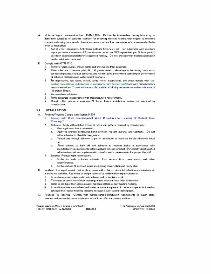
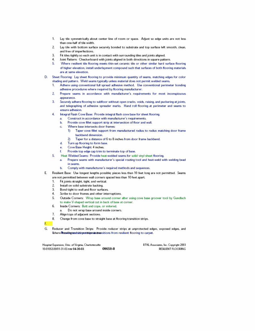
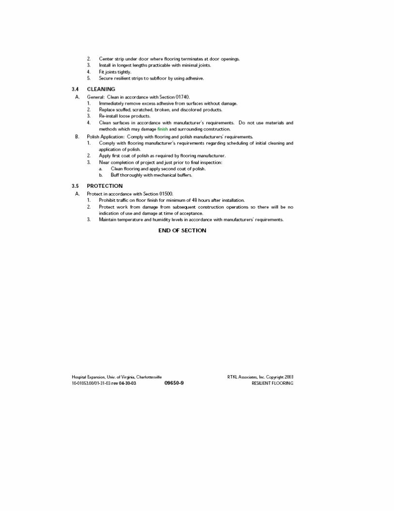
Elderly Apartment / 4-28-06 09 65 19 RESILIENT FLOORING
SECTION 09 65 19
RESILIENT TILE FLOORING
PART 1 GENERAL
1.01 SECTION INCLUDES
A. Resilient tile.
B. Edging strips.
C. Base.
D. Underlayment and floor patch.
E. Adhesives and primers.
1.02 MEASUREMENT AND PAYMENT
A. General: Resilient tile flooring and base will not be measured separately for payment
but will be paid for as part of the Contract lump sum price for Architectural Work.
1.03 REFERENCES
A. American Society for Testing and Materials (ASTM):
1. ASTM E84 Test Method for Surface Burning Characteristics of Building Materials
2. ASTM E648 Test Method for Critical Radiant Flux of Floor-Covering Systems
Using a Radiant Heat Energy Source
RESILIENT FLOORING 09 65 19 Elderly Apartment / 4-28-06
3. ASTM E662 Test Method for Specific Optical Density of Smoke Generated by
Solid Materials
B. Federal Specifications (FS):
1. SS-T-312 Tile, Floor: Asphalt, Rubber, Vinyl, Vinyl-Asbestos
2. SS-W-40 Wall Base: Rubber, and Vinyl Plastic
C. Resilient Floor Covering Institute (RFCI):
1. RFCI Installation Specifications
2. RFCI Wall Base
1.04 SUBMITTALS
A. General: Refer to Section 01 33 00 - Submittal Procedures, and Section 01 33 23 – Shop
Drawings, Product Data, and Samples, for submittal requirements and procedures.
B. Samples: Submit samples of resilient tile, resilient base, edge trim, and accessories.
Resilient tile and base require approval of the Engineer before they may be purchased
for this work.
PART 2 PRODUCTS
2.01 MATERIALS
A. Tile: Fed. Spec. SS-T-312, Type IV (composition). Resilient tile shall meet the
following requirements:
Elderly Apartment / 4-28-06 09 65 19 RESILIENT FLOORING
1. Flame Spread: 25 maximum when tested in accordance with ASTM E84.
2. Smoke Developed: 450 maximum when tested in accordance with ASTM E662.
3. Critical Radiant Flux: 0.45 minimum when tested in accordance with ASTM E648.
4. Gage: 1/8 inch.
5. Size, Color, and Pattern: As indicated, or as selected by the Engineer from
manufacturer’s standard colors and patterns. Color and pattern shall extend through
the body of the tile.
B. Edging Strips: Molded vinyl 1-1/2 inch by 1/8-inch thick, with exposed edge ¼-
rounded, in color as selected by the Engineer from manufacturer’s standards.
C. Base: Fed. Spec. SS-W-40, topset cove, solid vinyl or rubber.
1. Size: 4 inches high, unless otherwise indicated.
2. Color: As indicated, or as selected by the Engineer from manufacturer’s standard
colors.
D. Underlayment and Floor Patch: Floor patch and leveling compound or underlayment
shall be products manufactured for the purpose as recommended by the manufacturer
of the resilient flooring furnished.
E. Adhesives and Primers: Products specified or recommended by the manufacturers of the
particular resilient flooring and base furnished.
PART 3 EXECUTION
RESILIENT FLOORING 09 65 19 Elderly Apartment / 4-28-06
3.01 INSPECTION AND PREPARATION OF SURFACES
A. Inspection of Substrate Surfaces: Before starting the installation of resilient flooring and base,
examine all surfaces on which the finish flooring and base are to be applied. Examination
includes bond, moisture, and alkali testing of concrete subfloors. Any defective surfaces or
conditions preventing proper execution of the work shall be corrected as required.
B. Cleaning and Preparation of Substrate Surfaces: Subsurfaces and backing surfaces shall be dry,
clean of dust, paint spots, grease, and bond breaking or curing compounds. Subsurfaces shall
also be free from roughness and sharp edges to prevent protrusions and bulges after resilient
material is laid or applied. Fill all joints, cracks, and depressions in concrete slabs with
specified floor patch and underlayment material.
C. Beginning Work: Installation shall not begin until the work of other trades in the area, including
painting, has been completed.
D. Responsibility: Nothing specified herein shall be construed as relieving the Contractor of any
responsibility for the quality of the finished installation. Surfaces on which resilient flooring
and base are to be applied shall be level and in proper condition in every respect for an
acceptable installation and long life without defects.
3.02 INSTALLATION
A. Installation Standards: Comply with RFCI Installation Specifications and RFCI Wall Base.
B. Installation Requirements: Keep materials at a temperature of 70 degrees F or higher for at least
48 hours before using, and maintain 70 degrees F or higher room temperatures at least 3 days
before, during, and after application of materials. Apply materials in accordance with the
Elderly Apartment / 4-28-06 09 65 19 RESILIENT FLOORING
flooring manufacturer’s installation instructions. Materials shall be installed only by skilled
and experienced applicators authorized and approved by the flooring manufacturer.
C. Resilient Tile:
1. Tile Layout: Lay out center lines in both directions of room parallel to walls. Adjust to make
cut tile borders of equal width on opposite sides. Avoid using less-than-half-width tiles.
Lay tile with joints aligned and without contrasting borders. Lay tile with grain running in
the same direction.
2. Application of Adhesive: After joints, cracks, and depressions in concrete slabs have
been filled with floor patch and leveling compound, and floors have been primed (if
recommended by flooring manufacturer), apply the specified adhesive with a
notched steel trowel to ensure an even bed of adhesive for the tile. Cross-trowel to
achieve an even thickness.
3. Laying of Tile: Lay tile when adhesive has set tacky, starting at the center of the
room and working toward walls. Embed each tile in adhesive with closely fitted,
straight, hairline joints. Do not cut tile except at walls or obstructions. Neatly scribe
around pipes, fixtures, and equipment to form tight joints free of gaps. Finished
floors shall be smooth and free from buckles, cracks, breaks, waves, and projecting
edges and shall fit neatly at pipes and other installations and obstructions. Remove
excess adhesive.
4. Tile at Permanent Cabinets: Tile is not required under fixed cabinets having
covered fronts and integral bottoms and which are permanently anchored to the
structure.
RESILIENT FLOORING 09 65 19 Elderly Apartment / 4-28-06
5. Edging Strips: Install edging strips wherever tile terminates at an opening or where
there is an unprotected edge. Top of strips shall be flush with top of tile.
D. Base: Complete resilient flooring installation before applying base. Install base on all
walls as indicated and on fronts, toe spaces, and finished backs and ends of cabinets
with adhesive recommended by manufacturer of base. Apply adhesive to both wall and
base and press firmly into place. Maintain top edge at true horizontal line. Toe of coved
base shall contact floor for entire length. Closely butt end joints, top edge, and faces
flush. Remove excess adhesive.
3.03 CLEANING, SEALING, AND PROTECTION
A. Traffic: Until floors are well seated, at least 72 hours, at a maintained temperature of not
less than 70 degrees F, traffic shall be kept to a minimum, and fixtures, equipment,
trucks, and similar equipment or vehicles shall not be permitted to travel over floors.
B. Cleaning and Sealing: Just before turning station structure or building over to the District,
and not before, clean resilient flooring and base thoroughly in accordance with the
flooring manufacturer’s recommendations. After cleaning, apply one coat of approved
non-skid finish to floors and polish with a mechanical buffer.
C. Protection: Install clean plywood or board walks over clean, non-staining building paper
where any traffic from other trades must pass over completed resilient floors. Maintain
protection until acceptance by the District and Contract substantial completion.
END OF SECTION
SECTION 09 65 20
RESILIENT TILE FLOORING
PART 1 GENERAL 1.01 RELATED WORK SPECIFIED ELSEWHERE
A. Plywood Underlayment: Section 06100.
1.02 SUBMITTALS
A. Product Data: Manufacturer's specifications, and surface preparation and installation instructions, for each material specified except primer.
B. Samples:
1. Resilient Tile: Full size, each type, size, and color required. 2. Base: 12 inch long sections, each type, size, and color required. 3. Edge Strips: 12 inch long sections, each type and color required. 4. Color Samples: Manufacturer's standard colors, patterns, and textures.
C. Quality Control Submittals:
1. Certificates: Certificates required under Quality Assurance Article. D. Contract Closeout Submittals:
1. Maintenance Data: Deliver 2 copies covering the installed products, to the Director's Representative.
1.03 QUALITY ASSURANCE
A. Compatibility of Materials: For each type of tile specified, furnish associated
materials made by or recommended by the tile manufacturer. B. Certifications: Furnish certification from flooring installer that the substrate
surfaces have been examined and are acceptable for installation of the Work of this Section.
1.04 PROJECT CONDITIONS
A. Environmental Requirements: Continuously heat spaces to receive flooring to
a temperature of 68 degrees F for at least 48 hours prior to flooring installation, during the installation, and for 48 hours after installation.
B. Environmental Requirements: Make arrangements thru the Director's
Representative for having the temperature in the spaces to receive flooring
Elderly Apartment/11-21-06 09 65 20 - 1 Resilient Tile Flooring
maintained at 68 degrees F for 48 hours prior to flooring installation, during the installation, and for 48 hours after installation.
C. Condition flooring materials by placing them in the spaces where they will be
installed for at least 48 hours prior to installation.
1.05 MAINTENANCE
A. Extra Materials: 1. Furnish extra tile, equal to 2 percent of the tile installed, of each type
and color of tile required. The extra tile shall be from the same run and lot number as the installed tile.
2. Place extra materials in storage at the site where directed. PART 2 PRODUCTS 2.01 MATERIALS
A. Vinyl Composition Tile: FS SS-T-312, Type IV, Composition 1; 12 x 12 inch
size, 1/8 inch gage.
B. Vinyl Tile: FS SS-T-312, Type III; 12 x 12 inch size, 1/8 inch gage. C. Rubber Tile: FS SS-T-312, Type II; 12 x 12 inch size, 1/8 inch gage; smooth
surface.
D. Rubber Tile: Virgin rubber and finely ground stabilizing fillers, with fade-resistant color pigments, fire retardant compounds, migrating waxes and soil releasing agents; nominal 18 x 18 inch or 24 x 24 inch size, minimum 0.100 inch gage.
1. Surface Design: Raised circle, low profile (0.025 inch).
E. Asphalt Tile: FS SS-T-312, Type I; 9 x 9 inch size, 1/8 inch gage.
F. Rubber Base: FS SS-W-40, Type I; 4 inches high, 1/8 inch gage; with matching preformed external corner units.
G. Vinyl Base: FS SS-W-40, Type II; 4 inches high, 0.080 inch gage, with
matching preformed external corner units.
1. Style: Cove wall base with standard toe. 2. Style: Straight wall base without cove. 3. Adhesive and Filler/Wall Patch: As recommended by the base
manufacturer for the type of substrate indicated.
Elderly Apartment/11-21-06 09 65 20 - 2 Resilient Tile Flooring
H. Metal Edge Strips: Extruded aluminum, mill finish; butt type for concealed anchorage; countersunk stainless steel fasteners, with anchors suitable for type of subfloor indicated.
I. Resilient Edge Strips: Homogeneous vinyl; not less than one inch wide, 1/8
inch gage; tapered bullnose edge. 1. Color/Pattern: Matching floor tile.
J. Resilient Feature Strips: Same material composition and gage as adjoining floor
tile. Size and color/pattern shall be as shown on the Drawings.
K. Stair Covering Materials:
1. Stair Treads: Molded rubber, 1/4 inch thick at nose tapering to 1/8 inch thick at back edge; FS RR-T-650, Composition A, Type 2 - Designed; full width and depth of stair subtread in one piece; raised pattern design; square nose returning down edge of tread 1-1/2 inches.
2. Stair Risers: Molded rubber cove riser, 1/8 inch thick; full height and length of riser in one piece.
3. Stair Skirting: Sheet vinyl, minimum 0.080 inch thick; width sufficient to provide skirting (without longitudinal joints) extending 2 inches above stair nose, measured perpendicular to stair slope, unless otherwise shown.
4. Stair Nosings: Rubber, 1/4 inch thick; butt type, round nose; 3-1/2 inch serrated horizontal return and 1-1/2 inch return down edge of tread; full width of stair tread in one piece.
5. Adhesive: As recommended by the stair covering material manufacturer for the type of substrate indicated.
6. Void Filler: As recommended by the stair tread manufacturer to fill voids and open spaces at the nosing between the stair tread and stair substrate.
L. Underlayment:
1. Mastic Type: Latex underlayment or other mastic underlayment recommended by flooring material manufacturer for the type of substrate indicated.
2. Felt: No. 15 asphalt saturated felt.
M. Primer for Porous or Dusty Concrete: Tile adhesive manufacturer's recommended primer for preparation of porous or dusty concrete.
N. Tile Adhesive: Water resistant, formulated for application on type of subfloor
indicated, and recommended by the tile manufacturer.
O. Floor Finish: FS P-W-155; heavy traffic water emulsion floor wax, minimum 16 percent total solids.
Elderly Apartment/11-21-06 09 65 20 - 3 Resilient Tile Flooring
PART 3 EXECUTION 3.01 EXAMINATION
A. Verification of Conditions: 1. Examine substrate surfaces to receive the Work of this Section for
defects that will adversely affect the execution and quality of the Work. Do not proceed until unsatisfactory conditions are corrected, and installer's substrate surface acceptability certification has been acknowledged by the Director's Representative.
a. Concrete Subfloor Bond Tests: Check for surface moisture and coatings on concrete subfloor by bond tests as recommended by the tile manufacturer.
2. Do not install the Work of this Section until after all other finishing operations, including painting, have been completed unless otherwise indicated or directed by the Director's Representative.
a. Where movable partitions are indicated, install flooring before partitions are erected without interrupting floor pattern.
3.02 SURFACE PREPARATION
A. Unless otherwise specified, follow the materials manufacturers' written instructions.
B. Remove dirt, grease, oil, paint, varnish, wax, sealers, and other contaminants
which may impair the full bonding of the materials.
C. Concrete Subfloor: 1. Remove trowel marks or other projections by grinding or sanding. 2. Level uneven surfaces with smooth troweling of mastic underlayment.
Follow underlayment manufacturer's application and curing instructions. 3. Provide a substrate surface with not more than 1/8 inch in 10'-0"
variation from level or required slope. 4. If recommended by flooring material manufacturer, treat porous and
dusty concrete with primer after vacuum cleaning the surface. Apply primer at the rate recommended by the primer manufacturer.
D. Wood Strip Subfloor:
1. Renail loose boards. Remove broken and rotted boards and provide replacement boards.
2. Remove surface irregularities such as cups and warps by sanding. 3. Vacuum clean the entire subfloor. 4. If recommended by flooring material manufacturer, apply felt
underlayment to the entire subfloor, at right angles to the direction of the
Elderly Apartment/11-21-06 09 65 20 - 4 Resilient Tile Flooring
boards, with tight butt joints. Fit felt to the floor area. Fully cement the felt with linoleum paste or other approved adhesive. Press felt with a heavy roller to attain full adhesion and eliminate trapped air and voids.
E. Immediately before application of the flooring adhesive, vacuum clean the
prepared subfloor surface. 3.03 INSTALLATION
A. Install the flooring from center marks established with principal walls; lay out the tile field and adjust to avoid use of cut units less than one-half tile wide at perimeters. Match tile units for color and pattern by using the tile in manufactured and packaged sequence.
1. Lay all tile units with grain running in the same direction. 2. Lay tile units in "checkerboard" pattern with grain direction reversed in
alternate tiles.
B. Install tile units in adhesive bed in compliance with manufacturer's printed instructions. Butt tile units tightly to vertical surfaces, thresholds, nosings, and edgings. Scribe tile around obstructions and openings as necessary to produce neat joints. Install tile evenly in straight, parallel lines. Extend tile into toe spaces, door reveals, closets and other similar openings.
C. Install tile on pan type access cover plates for electrical and telephone ducts
and other such items which occur within finished resilient tile floor areas. Maintain color and pattern continuity with tile installed on such areas.
D. Install resilient edge strips at unprotected edges of flooring, unless otherwise
indicated.
E. Install metal edge strips where indicated. Securely fasten in place.
F. Install resilient base in compliance with manufacturer's printed instructions. Install base on walls, partitions, columns, and permanent fixtures unless otherwise indicated. Install base in as long lengths as practicable, with preformed external corner units. Miter internal corners. Scribe and fit base to door frames and other interruptions.
1. On masonry and other irregular surfaces, fill voids behind base with filler/wall patch.
G. Install stair covering materials in compliance with manufacturer's printed
instructions. Treads, risers, and nosings shall be installed in one piece per step. Closely fit each piece, and adhere over entire substrate surface. Closely fit skirting to stair and stringer profile.
1. Fill voids and open spaces at the nosing between the stair tread and stair substrate with void filler.
Elderly Apartment/11-21-06 09 65 20 - 5 Resilient Tile Flooring
3.04 CLEANING
A. Remove any excess adhesive and other surface soiling from face of installed materials with cleaning agents recommended by the manufacturer of the material being cleaned.
3.05 PROTECTION
A. Protect installed flooring from traffic and damage. Apply non-staining kraft paper covering where necessary. Maintain covering until directed to remove it by the Director's Representative.
3.06 FINISHING
A. Prior to the final inspection, when directed by the Director's Representative, thoroughly clean tile floors and accessories. Apply 2 coats of floor finish and buff to finish. Comply with the tile manufacturer's recommended cleaning, finishing, and buffing procedures.
END OF SECTION
Elderly Apartment/11-21-06 09 65 20 - 6 Resilient Tile Flooring
SECTION 09 68 00
CARPET
PART 1 GENERAL 1.01 SUBMITTALS
A. Shop Drawings: Show dimensions of carpeted areas, pattern direction, and seam diagram showing locations of all cuts, seams, edge strips, and other installation details. Where possible, locate seams in areas of least amount of traffic.
B. Product Data: Catalog sheets, specifications, and installation instructions for the following: 1. Carpet:
a. Trade name and number. b. Manufacturer. c. Address of mill constructing carpet. d. Construction type. e. Gage. f. Stitches per inch. g. Pile height. h. Face yarn. i. Face yarn weight. j. Weight density factor. k. Primary backing. l. Secondary backing. m. Total weight. n. Dye method. o. Tuft bind. p. Static resistance. q. Flammability.
2. Edge strips. 3. Adhesive and seam sealer.
C. Samples: 1. Carpet: One piece 18 inches x 27 inches of each type, color and pattern
specified. 2. Edge Strip: 12 inches long, each type specified. 3. Adhesive: One pint. 4. Color Samples: Manufacturer's standard color samples for carpet type
specified.
D. Quality Control Submittals: 1. Certificates: Affidavits required under Quality Assurance Article.
E. Contract Closeout Submittals: 1. Maintenance and Cleaning Instructions: Furnish 2 copies to the Director's
Representative. 2. Warranty: Copy of specified warranty.
Elderly Apartment / 11-21-06 09 68 00 Carpet
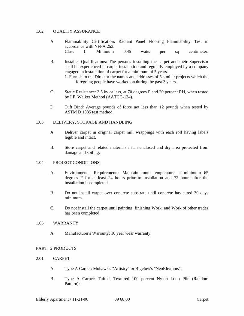
1.02 QUALITY ASSURANCE
A. Flammability Certification: Radiant Panel Flooring Flammability Test in accordance with NFPA 253. Class I: Minimum 0.45 watts per sq centimeter.
B. Installer Qualifications: The persons installing the carpet and their Supervisor
shall be experienced in carpet installation and regularly employed by a company engaged in installation of carpet for a minimum of 5 years. 1. Furnish to the Director the names and addresses of 5 similar projects which the
foregoing people have worked on during the past 3 years.
C. Static Resistance: 3.5 kv or less, at 70 degrees F and 20 percent RH, when tested by I.F. Walker Method (AATCC-134).
D. Tuft Bind: Average pounds of force not less than 12 pounds when tested by
ASTM D 1335 test method.
1.03 DELIVERY, STORAGE AND HANDLING
A. Deliver carpet in original carpet mill wrappings with each roll having labels legible and intact.
B. Store carpet and related materials in an enclosed and dry area protected from
damage and soiling.
1.04 PROJECT CONDITIONS
A. Environmental Requirements: Maintain room temperature at minimum 65 degrees F for at least 24 hours prior to installation and 72 hours after the installation is completed.
B. Do not install carpet over concrete substrate until concrete has cured 30 days
minimum. C. Do not install the carpet until painting, finishing Work, and Work of other trades
has been completed.
1.05 WARRANTY
A. Manufacturer's Warranty: 10 year wear warranty. PART 2 PRODUCTS 2.01 CARPET
A. Type A Carpet: Mohawk's "Artistry" or Bigelow's "NeoRhythms". B. Type A Carpet: Tufted, Textured 100 percent Nylon Loop Pile (Random
Pattern):
Elderly Apartment / 11-21-06 09 68 00 Carpet
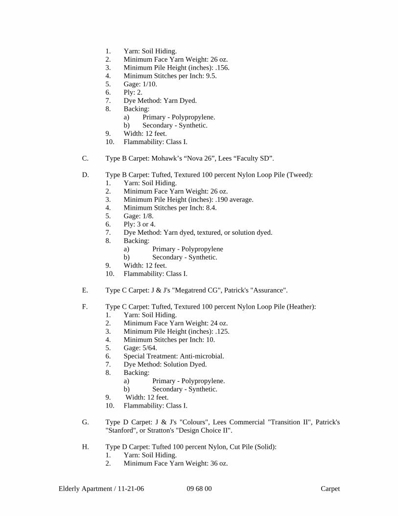
1. Yarn: Soil Hiding. 2. Minimum Face Yarn Weight: 26 oz. 3. Minimum Pile Height (inches): .156. 4. Minimum Stitches per Inch: 9.5. 5. Gage: 1/10. 6. Ply: 2. 7. Dye Method: Yarn Dyed. 8. Backing:
a) Primary - Polypropylene. b) Secondary - Synthetic.
9. Width: 12 feet. 10. Flammability: Class I.
C. Type B Carpet: Mohawk’s “Nova 26”, Lees “Faculty SD”. D. Type B Carpet: Tufted, Textured 100 percent Nylon Loop Pile (Tweed):
1. Yarn: Soil Hiding. 2. Minimum Face Yarn Weight: 26 oz. 3. Minimum Pile Height (inches): .190 average. 4. Minimum Stitches per Inch: 8.4. 5. Gage: 1/8. 6. Ply: 3 or 4. 7. Dye Method: Yarn dyed, textured, or solution dyed. 8. Backing:
a) Primary - Polypropylene b) Secondary - Synthetic.
9. Width: 12 feet. 10. Flammability: Class I.
E. Type C Carpet: J & J's "Megatrend CG", Patrick's "Assurance".
F. Type C Carpet: Tufted, Textured 100 percent Nylon Loop Pile (Heather): 1. Yarn: Soil Hiding. 2. Minimum Face Yarn Weight: 24 oz. 3. Minimum Pile Height (inches): .125. 4. Minimum Stitches per Inch: 10. 5. Gage: 5/64. 6. Special Treatment: Anti-microbial. 7. Dye Method: Solution Dyed. 8. Backing:
a) Primary - Polypropylene. b) Secondary - Synthetic.
9. Width: 12 feet. 10. Flammability: Class I.
G. Type D Carpet: J & J's "Colours", Lees Commercial "Transition II", Patrick's "Stanford", or Stratton's "Design Choice II".
H. Type D Carpet: Tufted 100 percent Nylon, Cut Pile (Solid):
1. Yarn: Soil Hiding. 2. Minimum Face Yarn Weight: 36 oz.
Elderly Apartment / 11-21-06 09 68 00 Carpet
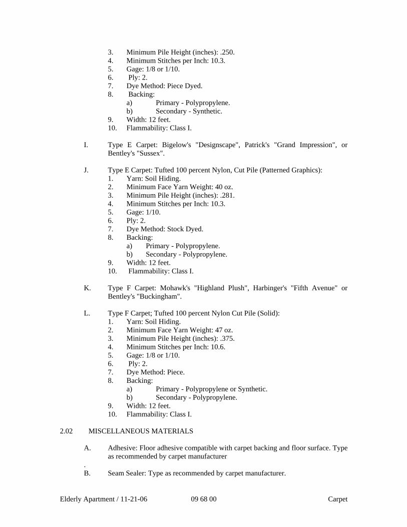
3. Minimum Pile Height (inches): .250. 4. Minimum Stitches per Inch: 10.3. 5. Gage: 1/8 or 1/10. 6. Ply: 2. 7. Dye Method: Piece Dyed. 8. Backing:
a) Primary - Polypropylene. b) Secondary - Synthetic.
9. Width: 12 feet. 10. Flammability: Class I.
I. Type E Carpet: Bigelow's "Designscape", Patrick's "Grand Impression", or Bentley's "Sussex".
J. Type E Carpet: Tufted 100 percent Nylon, Cut Pile (Patterned Graphics):
1. Yarn: Soil Hiding. 2. Minimum Face Yarn Weight: 40 oz. 3. Minimum Pile Height (inches): .281. 4. Minimum Stitches per Inch: 10.3. 5. Gage: 1/10. 6. Ply: 2. 7. Dye Method: Stock Dyed. 8. Backing:
a) Primary - Polypropylene. b) Secondary - Polypropylene.
9. Width: 12 feet. 10. Flammability: Class I.
K. Type F Carpet: Mohawk's "Highland Plush", Harbinger's "Fifth Avenue" or Bentley's "Buckingham".
L. Type F Carpet; Tufted 100 percent Nylon Cut Pile (Solid):
1. Yarn: Soil Hiding. 2. Minimum Face Yarn Weight: 47 oz. 3. Minimum Pile Height (inches): .375. 4. Minimum Stitches per Inch: 10.6. 5. Gage: 1/8 or 1/10. 6. Ply: 2. 7. Dye Method: Piece. 8. Backing:
a) Primary - Polypropylene or Synthetic. b) Secondary - Polypropylene.
9. Width: 12 feet. 10. Flammability: Class I.
2.02 MISCELLANEOUS MATERIALS
A. Adhesive: Floor adhesive compatible with carpet backing and floor surface. Type as recommended by carpet manufacturer
. B. Seam Sealer: Type as recommended by carpet manufacturer.
Elderly Apartment / 11-21-06 09 68 00 Carpet
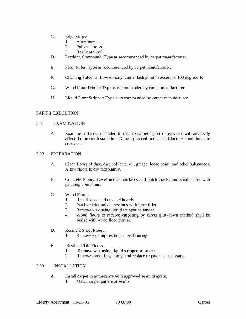
C. Edge Strips:
1. Aluminum. 2. Polished brass. 3. Resilient vinyl.
D. Patching Compound: Type as recommended by carpet manufacturer. E. Floor Filler: Type as recommended by carpet manufacturer. F. Cleaning Solvents: Low toxicity, and a flash point in excess of 100 degrees F. G. Wood Floor Primer: Type as recommended by carpet manufacturer. H. Liquid Floor Stripper: Type as recommended by carpet manufacturer.
PART 3 EXECUTION 3.01 EXAMINATION
A. Examine surfaces scheduled to receive carpeting for defects that will adversely affect the proper installation. Do not proceed until unsatisfactory conditions are corrected.
3.02 PREPARATION
A. Clean floors of dust, dirt, solvents, oil, grease, loose paint, and other substances. Allow floors to dry thoroughly.
B. Concrete Floors: Level uneven surfaces and patch cracks and small holes with
patching compound. C. Wood Floors:
1. Renail loose and cracked boards. 2. Patch cracks and depressions with floor filler. 3. Remove wax using liquid stripper or sander. 4. Wood floors to receive carpeting by direct glue-down method shall be
sealed with wood floor primer.
D. Resilient Sheet Floors: 1. Remove existing resilient sheet flooring.
E. Resilient Tile Floors: 1. Remove wax using liquid stripper or sander. 2. Remove loose tiles, if any, and replace or patch as necessary.
3.03 INSTALLATION
A. Install carpet in accordance with approved seam diagram. 1. Match carpet pattern at seams.
Elderly Apartment / 11-21-06 09 68 00 Carpet
B. Seaming: Treat edges cut for seaming with seam sealer. Apply the sealer along the edge of the carpet at the point where the face yarn goes into the back. Immediately remove excess sealer from face of pile with cleaning solvent recommended by seam sealer manufacturer.
C. Cut and fit carpet neatly around projections through floor and to walls and other
vertical surfaces. D. Direct Glue-Down Method: Apply adhesive in accordance with manufacturer's
instructions. Broom or roll carpet to remove air bubbles and insure bond. E. Stairs and Steps: Secure carpeting by anchorage methods recommended by carpet
manufacturer. F. Install edge strips where carpet terminates at other floor coverings or finishes.
Use one full length piece where possible. Where splicing cannot be avoided, butt ends tight and flush.
3.04 CLEANING AND PROTECTION
A. Upon completion of the carpet installation, immediately remove spots and smears of excessive adhesive from carpet with cleaning solvent. Remove loose pieces of face yard with sharp scissors.
B. Place all usable remnants of carpet in an area designated by the Director's
Representative. C. Remove all waste materials and tools. D. Upon completion, thoroughly vacuum clean carpeted areas.
E. After each area of carpet has been installed, protect from soiling and damage. F. Allow glue-down installation a minimum of 48 hours to cure before subjecting it
to any traffic, moving of furniture, or other heavy equipment.
END OF SECTION
Elderly Apartment / 11-21-06 09 68 00 Carpet
Elderly Apartment/ 4-28-06 09 72 10 - 1 Vinyl Wall Covering
SECTION 09 72 10
VINYL WALL COVERING
PART 1 GENERAL
1.01 SUMMARY
A. Section Includes:
1. Vinyl wall covering and trim.
1.02 SUBMITTALS
A. General: Submit in accordance with section 01330.
1. Submit submittals for Division 9 Sections involving exposed interior finishes with color, texture, pattern, etc. selections simultaneously with submittals for this section.
B. Product Data: Submit new for each product.
C. Shop Drawings: Submit drawings showing wall elevations without seaming layout.
D. Samples:
1. Submit manufacturer’s full range of 4 by 6 inch samples of wall covering specified for Architect’s color selection.
2. Submit 12 inch long sample of trim for each color specified.
E. Informational Submittals: Submit following packaged separately from other submittals:
1. Test Reports: Submit test report verifying flame/fuel/smoke rating tested by UL.
2. Manufacturer’s instructions.
1.03 QUALITY ASSURANCE
A. Applicator Qualifications: Company specializing in wall covering installation.
B. Regulatory Requirements: Test: ASTM E84
1. Flame Spread Index: Not exceed 25.
2. Smoke Density Index: Not exceed 50.
1.04 FIELD SAMPLES
A. General: Comply with Section 01400.
Vinyl Wall Covering 09 72 10 - 2 Elderly Apartment/ 4-28-06
B. Sample Installation: Install three full sized panels in each color and pattern in full height and width in area designated by Architect.
1. Show edge treatment and installed wall covering and joint seaming techniques.
2. Accepted Field Sample: May remain part of completed work.
1.05 DELIVERY, STORAGE AND HANDLING
A. Delivery, store, handle, and protect products under provisions of Section 01600.
1. Inspect roll materials on site to verify acceptance.
2. Protect packaged adhesive from temperature cycling and cold temperatures.
3. Do not store roll goods on end.
1.06 ENVIRONMENTAL REQUIREMENTS
A. Provide continuous ventilation and heating to maintain surface and ambient temperatures above 65 F within area of work once wall covering installation is started.
1. Do not apply adhesive when substrate surface temperature or ambient temperature is below 60 F, or when relative humidity is above 40 percent, unless otherwise required by manufacturer’s instructions.
2. [Indoor Air Quality Procedures: Ventilate in accordance with Section 01355.]
B. Provide illumination of greater than 80 foot candles measured mid-height at substrate surface while painting is in progress.
1.07 MAINTENANCE
A. Extra Materials: Furnish in accordance with Section 1780.
1. Provide 25 lineal feet of each color and type of wall covering.
2. Package and label each roll by installation room number; store where directed.
3. Furnish replacement materials from same production run as installed materials.
PART 2 PRODUCTS
2.01 MANUFACTURERS
A. Acceptable Manufacturers: Refer to Finish Schedule.
2.02 MATERIALS
A. Vinyl Wall Covering: ASTM F793 Category V, Type II Commercial Serviceability.
Elderly Apartment/ 4-28-06 09 72 10 - 3 Vinyl Wall Covering
1. Style, Color, Pattern, Texture: Refer to Finish Schedule.
B. Adhesives: Type recommended by wall covering manufacturer to suit application to substrate; water based.
1. Provide adhesive which is mildew resistant and non-staining.
2. Volatile Organic Compound: Meet code requirements.
C. Substrate Filler: As recommended by adhesive and wall covering manufacturers; compatible with substrate.
D. Substrate Primer and Sealer: As recommended by wall covering manufacturer.
E. Termination Trim: Extruded plastic; color to be selected.
PART 3 EXECUTION
3.01 EXAMINATION
A. Examine conditions and proceed with work in accordance with Section 01400.
3.02 PREPARATION
A. Remove electrical and telephone plates.
1. Correct minor defects and clean substrates.
2. Sand glassy surfaces; shellac marks which may bleed.
3. Vacuum clean surfaces free of loose particles.
4. Apply one coat [two coats] of primer sealer to substrate surfaces.
B. Remove wall covering materials from packaging and allow to acclimatize to area of installation 24 hours before application.
3.03 VINYL WALL COVERING INSTALLATION
A. Apply adhesive and wall covering in accordance with Section 01600.
B. Use wall covering in roll number sequence.
1. Razor trim edges on flat work table. Do not razor cut on gypsum board surfaces.
C. Wall Covering Installation: Apply wall covering smooth, without wrinkles, gaps or overlaps.
1. Eliminate air pockets and fully bond to substrate surface.
Vinyl Wall Covering 09 72 10 - 4 Elderly Apartment/ 4-28-06
2. Butt edges tight.
3. Hang by reversing alternate strips except on matched patterns.
4. Install seams vertically and plumb, at least 6 inches away from any corner.
5. Trim selvages to provide color uniformity and pattern match at seams.
6. Install wall covering before installation of bases, hardware, [cabinets], or items attached to or spaced slightly from wall surface.
7. Do not install wall covering more than 1/4 inch below top of resilient base.
D. Termination Trim: Install at exposed terminations of wall covering.
E. Remove excess wet adhesive from seam before proceeding to next wall covering sheet. Wipe clean with dry cloth.
3.04 CLEANING AND PROTECTION
A. Cleaning: Comply with Section 01740. Clean as recommended by manufacturer. Do not use materials or methods which may damage finish or surrounding construction.
1. Clean wall covering of excess adhesive, dust, dirt and other contaminants.
2. Replace wall plates and accessories removed prior to installation.
B. Protection: Protect finished work in accordance with Section 01500.
END OF SECTION
SECTION 09 90 00
PAINTING AND COATING
PART 1 GENERAL 1.01 RELATED DOCUMENTS
A. Drawings and general provisions of the Contract, including General and Supplementary Conditions and Division 1 Specification Sections, apply to this section.
1.02 SUMMARY
A. This section includes surface preparation and field painting of the following:
1. Exposed exterior items and surfaces. 2. Exposed interior items and surfaces. 3. Surface preparation, priming, and finish coats specified in this Section are
in addition to shop priming and surface treatment specified in other Sections. Revise paragraph below to suit the Project.
B. Related Sections include the following:
1. Division 5 Section “Structural Steel” for shop priming structural steel. 2. Division 5 Section “Metal Fabrications” for shop priming ferrous metal. 3. Division 8 Section “Steel Doors and Frames” for shop priming steel doors
and frames. 4. Division 9 Section “Gypsum Board Assemblies” for surface preparation
for gypsum board. 5. Division 9 Section “Special Coatings” for industrial paints and
maintenance and special coatings. 6. Division 9 Section “Multicolored Interior Coatings” for spray-applied
multicolored coatings. 1.03 DEFINITIONS
A. General: Standard coating terms defined in ASTM D16 apply to this section.
1. Eggshell refers to a low-sheen finish with a gloss range between 5 and 20 when measured with a 60-degree meter.
2. Satin refers to a low-sheen finish with a gloss range between 15 and 35 when measured with a 60-degree meter.
3. Full gloss refers to a high-sheen finish with a gloss range higher than 65 when measured with a 60-degree meter.
PAINTING AND COATING 09 90 00 - 1 Elderly Apartment / 11-20-06
Section 09 90 00
1.04 SUBMITTALS
A. Product Data: For each paint system specified. Include block fillers and primers.
1. Material List: Provide an inclusive list of required coating materials. Indicate each material and cross-reference specific coating, finish system, and application. Identify each material by manufacturer’s catalog number and coating material proposed for use.
2. Manufacturer’s Information: Provide manufacturer’s technical
information, including label analysis and instructions for handling, storing and applying each coating material proposed for use.
3. Certification by the manufacturer that products supplied comply with local
regulations controlling use of volatile organic compounds (VOC’s). B. Samples for Initial Selection: Manufacturer’s color charts showing the full range of colors available for each type of finish-coat material indicated.
1. After color selection, the Architect will furnish color chips for surfaces to
be coated.
C. Product Data Sheets and MSDS for each product to be used as required by the U.S.G.B.C. as proof that each product meets the requirements of either Green Seal’s GS-11 or GC-03 documents. This is a requirement in order to receive the possible one point for Credit 4.2 for Low-Emitting Materials in the Indoor Environmental Quality section of the Leadership in Energy and Environmental Design initiative of the U.S. Green Building Council.
1.05 QUALITY ASSURANCE
A. Applicator Qualifications: Engage an experienced applicator that has completed painting system applications similar in material and extent to that indicated for this Project with a record of successful in-service performance.
B. Source Limitations: Obtain block fillers, primers and undercoat materials for each
coating system from the same manufacturer as the finish coats. 1.06 DELIVERY, STORAGE AND HANDLING
A. Deliver materials to the Project Site in manufacturer’s original, unopened packages and containers bearing manufacturer’s name and label, and the following information:
PAINTING AND COATING 09 90 00 - 2 Elderly Apartment / 11-20-06
Section 09 90 00
1. Product name or title of material. 2. Product description (generic classification or binder type). 3. Manufacturer’s stock number and date of manufacture. 4. Contents by volume, for pigment and vehicle constituents. 5. Thinning instructions. 6. Application instructions. 7. Color name and number. 8. VOC content.
B. Store materials not in use in tightly covered containers in a well-ventilated area at a minimum ambient temperature of 45 degrees F (7 degrees C). Maintain containers used in storage in a clean condition, free of foreign materials and residue.
1. Protect from freezing. Keep storage area neat and orderly. Remove oily
rags and waste daily. Take necessary measures to ensure that workers and work areas are protected from fire and health hazards resulting from handling, mixing and application.
1.07 PROJECT CONDITIONS
A. Apply water-based paints only when the temperature of surfaces to be painted and surrounding air temperatures are between 50 and 90 degrees F (10 and 32 degrees C).
B. Apply solvent-thinned paints only when the temperature of surfaces to be painted
and surrounding air temperatures are between 45 and 95 degrees F (7.2 and 35 degrees C).
C. Do not apply paint in snow, rain, fog, or mist, or when the relative humidity
exceeds 85 percent, or at temperatures less than 5 degrees F (3 degrees C) above the dew point, or to damp or wet surfaces.
1. Painting may continue during inclement weather if surfaces and areas to be painted are enclosed and heated within temperature limits specified by manufacturer during application and drying periods.
PART 2 PRODUCTS 2.01 MANUFACTURERS
PAINTING AND COATING 09 90 00 - 3 Elderly Apartment / 11-20-06
Section 09 90 00
A. Products: Subject to compliance with requirements, provide one of the products in the paint schedules.
B. Manufacturers Names: The following manufacturer is referred to in the paint schedule by use if shortened versions of the name, which is shown below.
1. Pittsburgh Paints, PPG Industries, Inc.
2.02 PAINT MATERIALS, GENERAL
Material Compatibility: Provide block fillers, primers, undercoaters, and finish-coat materials that are compatible with one another and the substrates indicated under conditions of service and application, as demonstrated by manufacturer based on testing and field experience.
B. Material Quality: Provide manufacturer’s best-quality “professional” paint
material of the various coating types specified. Paint-material containers not displaying manufacturer’s product identification will not be acceptable.
1. Proprietary Names: Use of manufacturer’s proprietary product names to
designate colors or materials is not intended to imply that products named are required to be used to the exclusion of equivalent products of other manufacturers. Furnish manufacturer’s material data and certificates of performance for proposed substitutions.
C. Colors: Provide color matches indicated by reference to manufacturer’s color
designations. 2.03 CONCRETE MASONRY UNIT BLOCK FILLERS (Note: Block fillers are
classified by LEED as sealants and allowed to contain up to 250 g/L VOC and fall under Credit 4.1)
A. Concrete Masonry Unit Block Fillers: Factory formulated high-performance latex
block fillers
1. Pittsburgh Paints®; 6-7 SPEEDHIDE® Interior/ Exterior Masonry Latex Block Filler (28 g/L VOC): Applied at a dry film thickness of not less than 4.8 to 14.0 mils.
PAINTING AND COATING 09 90 00 - 4 Elderly Apartment / 11-20-06
Section 09 90 00
2. Pittsburgh Paints®; 6-15 SPEEDHIDE® Int./Ext. Acrylic Masonry Block Filler (47.50 g/L VOC) Applied at a dry film thickness of not less than 7.0mils.
2.04 EXTERIOR PRIMERS (DOES NOT AFFECT LEED STATUS BUT THE PRODUCTS LISTED HERE ARE COMPLIANT WITH GREENSEAL DOCUMENT GS-11)
A. Exterior Concrete and Masonry Primer: Factory-formulated alkali-resistant acrylic-latex primer for exterior application.
1. Pittsburgh Paints®; 4-603 PERMA-CRETE® Interior/Exterior Alkali Resistant Primer (110 g/L VOC): Applied at a dry film thickness of not less than 1.2 mils
B. Exterior Gypsum Soffit Board Primer: Factory-formulated alkyd- or alkali-resistant acrylic-latex primer for exterior application.
1. Pittsburgh Paints®; 6-609 SPEEDHIDE® Exterior House & Trim Wood Primer 100 Percent Acrylic Latex (89 g/L VOC): Applied at a dry film thickness of not less than 1.3 mils
C. Exterior Wood Primer for Acrylic Enamels: Factory-formulated alkyd or latex wood primer for exterior application.
1. Pittsburgh Paints®; 17-21 SEAL GRIP® Interior/Exterior Acrylic Latex Stain Blocking Primer (96 g/L VOC): Applied at a dry film thickness of not less than 1.2 mils
D. Exterior Ferrous-Metal Primer: Factory-formulated rust-inhibitive metal primer for exterior application.
1. Pittsburgh Paints®; 90-715 Pitt-Tech® One Pack Interior/Exterior Primer Finish DTM Industrial Enamel (250 g/L VOC corrosion protection product): Applied at a dry film thickness of not less than 3.0 mils
E. Exterior Galvanized Metal Primer: Factory-formulated galvanized metal primer for exterior application.
1. Pittsburgh Paints®; 90-715 Pitt-Tech® One Pack Interior/Exterior Primer/Finish DTM Industrial Enamel (250 g/L VOC corrosion protection product): Applied at a dry film thickness of not less than 3.0 mils
F. Exterior Aluminum Primer under Acrylic Finishes: Factory-formulated acrylic-based metal primer for exterior application.
PAINTING AND COATING 09 90 00 - 5 Elderly Apartment / 11-20-06
Section 09 90 00
1. Pittsburgh Paints®; 90-715 Pitt-Tech® One Pack Interior/Exterior Primer/Finish DTM Industrial Enamel (250 g/L VOC corrosion protection product): Applied at a dry film thickness of not less than 3.0 mils
2.05 INTERIOR PRIMERS
A. Interior Concrete and Masonry Primer: Factory-formulated alkali-resistant acrylic-latex interior primer for interior application.
1. Pittsburgh Paints®; 4-603 PERMA-CRETE® Interior/Exterior Alkali Resistant Primer (110 g/L VOC): Applied at a dry film thickness of not less than 1.2 mils
2. Pittsburgh Paints®; 9-900 Pure Performance® Interior Latex Primer Sealer (0 g/L VOC). Applied at a dry film thickness of not less than 1.4 mils.
B. Interior Gypsum Board Primer: Factory-formulated latex-based primer for interior application.
1. Pittsburgh Paints®; 4-603 PERMA-CRETE® Interior/Exterior Alkali Resistant Primer (110 g/L VOC): Applied at a dry film thickness of not less than 1.2 mils
2. Pittsburgh Paints®; 9-900 Pure Performance Interior Latex Primer (0.00 g/L VOC): Applied at a dry film thickness of not less than 1.4 mils.
C. Interior Plaster Primer: Factory-formulated latex-based primer for interior application.
1. Pittsburgh Paints; 4-603 PERMA-CRETE® Interior/Exterior Alkali Resistant Primer (110 g/L VOC): Applied at a dry film thickness of not less than 1.2 mils
2. Pittsburgh Paints®; 9-900 Pure Performance Interior Latex Primer (0.00 g/L VOC): Applied at a dry film thickness of not less than 1.4 mils.
D. Interior Wood Primer for Acrylic-Enamel and Semigloss Alkyd-Enamel Finishes: Factory-formulated acrylic-latex-based interior wood primer.
1. Pittsburgh Paints®; 17-21 SEAL GRIP® Interior/Exterior Acrylic Latex Stain Blocking Primer (96 g/L VOC): Applied at a dry film thickness of not less than 1.2 mils
2. Pittsburgh Paints®; 9-900 Pure Performance Interior Latex Primer (0.00 g/L VOC): Applied at a dry film thickness of not less than 1.4 mils.
PAINTING AND COATING 09 90 00 - 6 Elderly Apartment / 11-20-06
Section 09 90 00
E. Interior Wood Primer for Full-Gloss Enamel Finishes: Factory-formulated acrylic-latex-based interior wood primer.
1. Pittsburgh Paints®; 17-21 SEAL GRIP® Interior/Exterior Acrylic Latex Stain Blocking Primer (96 g/L VOC): Applied at a dry film thickness of not less than 1.2 mils
2. Pittsburgh Paints®; 9-900 Pure Performance Interior Latex Primer (0.00 g/L VOC): Applied at a dry film thickness of not less than 1.2 mils.
F. Interior Ferrous-Metal Primer: Factory-formulated quick-drying rust-inhibitive alkyd-based metal primer.
1. Pittsburgh Paints®; 90-715 Pitt-Tech® One Pack Interior/Exterior Primer/Finish DTM Industrial Enamel (250 g/L VOC Compliant due to anti-corrosive properties): Applied at a dry film thickness of not less than 2.0 mils
G. Interior Zinc-Coated Metal Primer: Factory-formulated galvanized metal primer.
1. Pittsburgh Paints®; 90-715 Pitt-Tech® One Pack Interior/Exterior Primer/Finish DTM Industrial Enamel (250 g/L VOC Compliant due to anti-corrosive properties : Applied at a dry film thickness of not less than 2.0 mils
2.06 EXTERIOR FINISH COATS (DOES NOT AFFECT LEED STATUS BUT THE PRODUCTS LISTED HERE ARE COMPLIANT WITH GREENSEAL DOCUMENT GS-11)
A. Exterior Flat Acrylic Paint: Factory-formulated flat acrylic-emulsion latex paint for exterior application.
1. Pittsburgh Paints®; 6-610 Series SpeedHide® Exterior House Paint Flat Latex (85.2 g/L VOC): Applied at a dry film thickness of not less than 1.0 mils
B. Exterior Low-Luster Acrylic Paint: Factory-formulated low-sheen (eggshell) acrylic-latex paint for exterior application.
1. Pittsburgh Paints®; 6-2045 Series SpeedHide® Exterior House & Trim Satin--Acrylic Latex (128 g/L VOC): Applied at a dry film thickness of not less than 0.8 mil
2. Pittsburgh Paints®; 90-474 Series Pitt-Tech® One Pack High Performance Waterborne Satin DTM Industrial Enamels (227 g/L VOC corrosion protection product): Applied at a dry film thickness of not less than 2.0 mils
PAINTING AND COATING 09 90 00 - 7 Elderly Apartment / 11-20-06
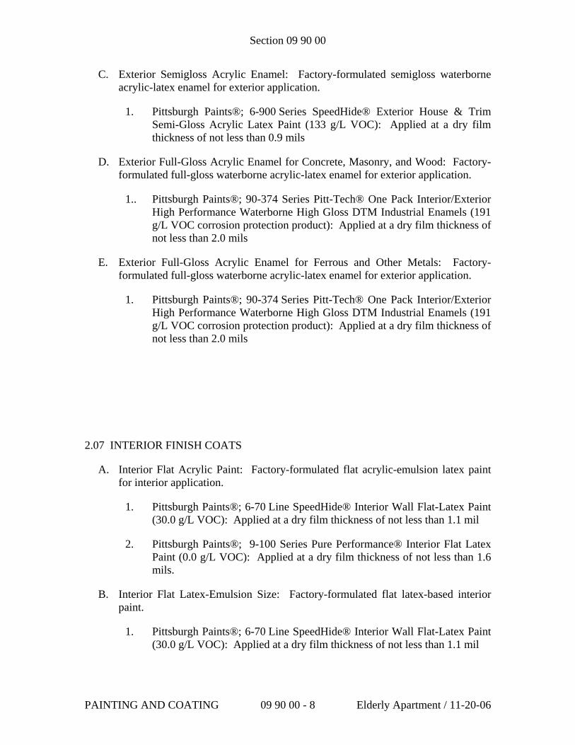
Section 09 90 00
C. Exterior Semigloss Acrylic Enamel: Factory-formulated semigloss waterborne acrylic-latex enamel for exterior application.
1. Pittsburgh Paints®; 6-900 Series SpeedHide® Exterior House & Trim Semi-Gloss Acrylic Latex Paint (133 g/L VOC): Applied at a dry film thickness of not less than 0.9 mils
D. Exterior Full-Gloss Acrylic Enamel for Concrete, Masonry, and Wood: Factory-formulated full-gloss waterborne acrylic-latex enamel for exterior application.
1.. Pittsburgh Paints®; 90-374 Series Pitt-Tech® One Pack Interior/Exterior High Performance Waterborne High Gloss DTM Industrial Enamels (191 g/L VOC corrosion protection product): Applied at a dry film thickness of not less than 2.0 mils
E. Exterior Full-Gloss Acrylic Enamel for Ferrous and Other Metals: Factory-formulated full-gloss waterborne acrylic-latex enamel for exterior application.
1. Pittsburgh Paints®; 90-374 Series Pitt-Tech® One Pack Interior/Exterior High Performance Waterborne High Gloss DTM Industrial Enamels (191 g/L VOC corrosion protection product): Applied at a dry film thickness of not less than 2.0 mils
2.07 INTERIOR FINISH COATS
A. Interior Flat Acrylic Paint: Factory-formulated flat acrylic-emulsion latex paint for interior application.
1. Pittsburgh Paints®; 6-70 Line SpeedHide® Interior Wall Flat-Latex Paint (30.0 g/L VOC): Applied at a dry film thickness of not less than 1.1 mil
2. Pittsburgh Paints®; 9-100 Series Pure Performance® Interior Flat Latex Paint (0.0 g/L VOC): Applied at a dry film thickness of not less than 1.6 mils.
B. Interior Flat Latex-Emulsion Size: Factory-formulated flat latex-based interior paint.
1. Pittsburgh Paints®; 6-70 Line SpeedHide® Interior Wall Flat-Latex Paint (30.0 g/L VOC): Applied at a dry film thickness of not less than 1.1 mil
PAINTING AND COATING 09 90 00 - 8 Elderly Apartment / 11-20-06
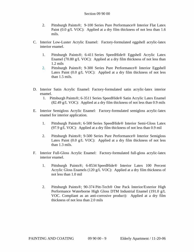
Section 09 90 00
2. Pittsburgh Paints®; 9-100 Series Pure Performance® Interior Flat Latex Paint (0.0 g/L VOC): Applied at a dry film thickness of not less than 1.6 mils.
C. Interior Low-Luster Acrylic Enamel: Factory-formulated eggshell acrylic-latex interior enamel.
1. Pittsburgh Paints®; 6-411 Series SpeedHide® Eggshell Acrylic Latex Enamel (70.80 g/L VOC): Applied at a dry film thickness of not less than 1.2 mils
2. Pittsburgh Paints®; 9-300 Series Pure Performance® Interior Eggshell Latex Paint (0.0 g/L VOC): Applied at a dry film thickness of not less than 1.5 mils.
D. Interior Satin Acrylic Enamel: Factory-formulated satin acrylic-latex interior enamel.
1. Pittsburgh Paints®; 6-3511 Series SpeedHide® Satin Acrylic Latex Enamel (82.49 g/L VOC): Applied at a dry film thickness of not less than 0.9 mils
E. Interior Semigloss Acrylic Enamel: Factory-formulated semigloss acrylic-latex enamel for interior application.
1. Pittsburgh Paints®; 6-500 Series SpeedHide® Interior Semi-Gloss Latex (97.9 g/L VOC): Applied at a dry film thickness of not less than 0.9 mil
2. Pittsburgh Paints®; 9-500 Series Pure Performance® Interior Semigloss Latex Paint (0.0 g/L VOC): Applied at a dry film thickness of not less than 1.3 mils.
F. Interior Full-Gloss Acrylic Enamel: Factory-formulated full-gloss acrylic-latex interior enamel.
1. Pittsburgh Paints®; 6-8534 SpeedHide® Interior Latex 100 Percent Acrylic Gloss Enamels (120 g/L VOC): Applied at a dry film thickness of not less than 1.0 mil
2. Pittsburgh Paints®; 90-374 Pitt-Tech® One Pack Interior/Exterior High
Performance Waterborne High Gloss DTM Industrial Enamel (191.0 g/L VOC. Compliant as an anti-corrosive product): Applied at a dry film thickness of not less than 2.0 mils
PAINTING AND COATING 09 90 00 - 9 Elderly Apartment / 11-20-06
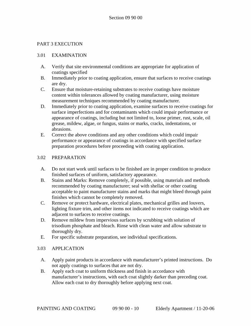
Section 09 90 00
PART 3 EXECUTION
3.01 EXAMINATION
A. Verify that site environmental conditions are appropriate for application of coatings specified
B. Immediately prior to coating application, ensure that surfaces to receive coatings are dry.
C. Ensure that moisture-retaining substrates to receive coatings have moisture content within tolerances allowed by coating manufacturer, using moisture measurement techniques recommended by coating manufacturer.
D. Immediately prior to coating application, examine surfaces to receive coatings for surface imperfections and for contaminants which could impair performance or appearance of coatings, including but not limited to, loose primer, rust, scale, oil grease, mildew, algae, or fungus, stains or marks, cracks, indentations, or abrasions.
E. Correct the above conditions and any other conditions which could impair performance or appearance of coatings in accordance with specified surface preparation procedures before proceeding with coating application.
3.02 PREPARATION
A. Do not start work until surfaces to be finished are in proper condition to produce finished surfaces of uniform, satisfactory appearance.
B. Stains and Marks: Remove completely, if possible, using materials and methods recommended by coating manufacturer; seal with shellac or other coating acceptable to paint manufacturer stains and marks that might bleed through paint finishes which cannot be completely removed.
C. Remove or protect hardware, electrical plates, mechanical grilles and louvers, lighting fixture trim, and other items not indicated to receive coatings which are adjacent to surfaces to receive coatings.
D. Remove mildew from impervious surfaces by scrubbing with solution of trisodium phosphate and bleach. Rinse with clean water and allow substrate to thoroughly dry.
E. For specific substrate preparation, see individual specifications. 3.03 APPLICATION
A. Apply paint products in accordance with manufacturer’s printed instructions. Do not apply coatings to surfaces that are not dry.
B. Apply each coat to uniform thickness and finish in accordance with manufacturer’s instructions, with each coat slightly darker than preceding coat. Allow each coat to dry thoroughly before applying next coat.
PAINTING AND COATING 09 90 00 - 10 Elderly Apartment / 11-20-06
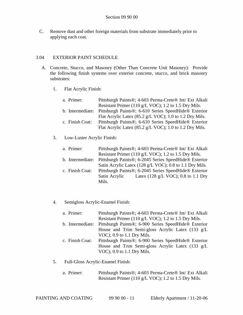
Section 09 90 00
C. Remove dust and other foreign materials from substrate immediately prior to applying each coat.
3.04 EXTERIOR PAINT SCHEDULE
A. Concrete, Stucco, and Masonry (Other Than Concrete Unit Masonry): Provide the following finish systems over exterior concrete, stucco, and brick masonry substrates:
1. Flat Acrylic Finish: a. Primer: Pittsburgh Paints®; 4-603 Perma-Crete® Int/ Ext Alkali
Resistant Primer (110 g/L VOC); 1.2 to 1.5 Dry Mils. b. Intermediate: Pittsburgh Paints®; 6-610 Series SpeedHide® Exterior
Flat Acrylic Latex (85.2 g/L VOC); 1.0 to 1.2 Dry Mils. c. Finish Coat: Pittsburgh Paints®; 6-610 Series SpeedHide® Exterior
Flat Acrylic Latex (85.2 g/L VOC); 1.0 to 1.2 Dry Mils.
3. Low-Luster Acrylic Finish:
a. Primer: Pittsburgh Paints®; 4-603 Perma-Crete® Int/ Ext Alkali Resistant Primer (110 g/L VOC); 1.2 to 1.5 Dry Mils.
b. Intermediate: Pittsburgh Paints®; 6-2045 Series SpeedHide® Exterior Satin Acrylic Latex (128 g/L VOC); 0.8 to 1.1 Dry Mils.
c. Finish Coat: Pittsburgh Paints®; 6-2045 Series SpeedHide® Exterior Satin Acrylic Latex (128 g/L VOC); 0.8 to 1.1 Dry Mils.
4. Semigloss Acrylic-Enamel Finish:
a. Primer: Pittsburgh Paints®; 4-603 Perma-Crete® Int/ Ext Alkali Resistant Primer (110 g/L VOC); 1.2 to 1.5 Dry Mils.
b. Intermediate: Pittsburgh Paints®; 6-900 Series SpeedHide® Exterior House and Trim Semi-gloss Acrylic Latex (133 g/L VOC); 0.9 to 1.1 Dry Mils.
c. Finish Coat: Pittsburgh Paints®; 6-900 Series SpeedHide® Exterior House and Trim Semi-gloss Acrylic Latex (133 g/L VOC); 0.9 to 1.1 Dry Mils.
5. Full-Gloss Acrylic-Enamel Finish:
a. Primer: Pittsburgh Paints®; 4-603 Perma-Crete® Int/ Ext Alkali Resistant Primer (110 g/L VOC); 1.2 to 1.5 Dry Mils.
PAINTING AND COATING 09 90 00 - 11 Elderly Apartment / 11-20-06
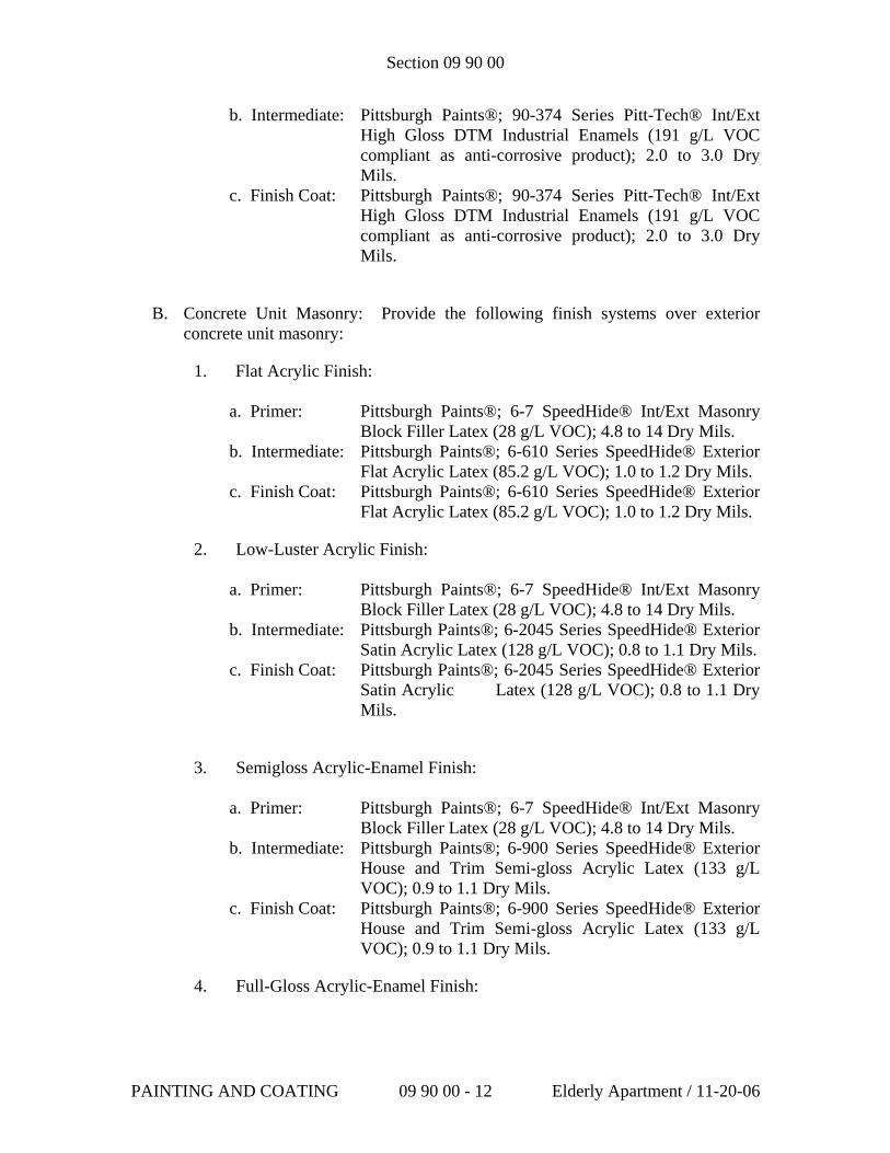
Section 09 90 00
b. Intermediate: Pittsburgh Paints®; 90-374 Series Pitt-Tech® Int/Ext High Gloss DTM Industrial Enamels (191 g/L VOC compliant as anti-corrosive product); 2.0 to 3.0 Dry Mils.
c. Finish Coat: Pittsburgh Paints®; 90-374 Series Pitt-Tech® Int/Ext High Gloss DTM Industrial Enamels (191 g/L VOC compliant as anti-corrosive product); 2.0 to 3.0 Dry Mils.
B. Concrete Unit Masonry: Provide the following finish systems over exterior concrete unit masonry:
1. Flat Acrylic Finish: a. Primer: Pittsburgh Paints®; 6-7 SpeedHide® Int/Ext Masonry
Block Filler Latex (28 g/L VOC); 4.8 to 14 Dry Mils. b. Intermediate: Pittsburgh Paints®; 6-610 Series SpeedHide® Exterior
Flat Acrylic Latex (85.2 g/L VOC); 1.0 to 1.2 Dry Mils. c. Finish Coat: Pittsburgh Paints®; 6-610 Series SpeedHide® Exterior
Flat Acrylic Latex (85.2 g/L VOC); 1.0 to 1.2 Dry Mils.
2. Low-Luster Acrylic Finish:
a. Primer: Pittsburgh Paints®; 6-7 SpeedHide® Int/Ext Masonry Block Filler Latex (28 g/L VOC); 4.8 to 14 Dry Mils.
b. Intermediate: Pittsburgh Paints®; 6-2045 Series SpeedHide® Exterior Satin Acrylic Latex (128 g/L VOC); 0.8 to 1.1 Dry Mils.
c. Finish Coat: Pittsburgh Paints®; 6-2045 Series SpeedHide® Exterior Satin Acrylic Latex (128 g/L VOC); 0.8 to 1.1 Dry Mils.
3. Semigloss Acrylic-Enamel Finish:
a. Primer: Pittsburgh Paints®; 6-7 SpeedHide® Int/Ext Masonry Block Filler Latex (28 g/L VOC); 4.8 to 14 Dry Mils.
b. Intermediate: Pittsburgh Paints®; 6-900 Series SpeedHide® Exterior House and Trim Semi-gloss Acrylic Latex (133 g/L VOC); 0.9 to 1.1 Dry Mils.
c. Finish Coat: Pittsburgh Paints®; 6-900 Series SpeedHide® Exterior House and Trim Semi-gloss Acrylic Latex (133 g/L VOC); 0.9 to 1.1 Dry Mils.
4. Full-Gloss Acrylic-Enamel Finish:
PAINTING AND COATING 09 90 00 - 12 Elderly Apartment / 11-20-06
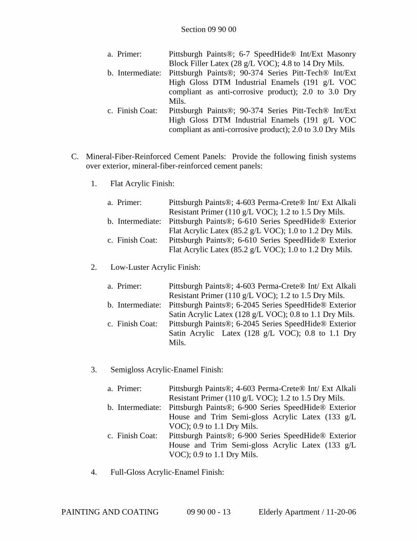
Section 09 90 00
a. Primer: Pittsburgh Paints®; 6-7 SpeedHide® Int/Ext Masonry Block Filler Latex (28 g/L VOC); 4.8 to 14 Dry Mils.
b. Intermediate: Pittsburgh Paints®; 90-374 Series Pitt-Tech® Int/Ext High Gloss DTM Industrial Enamels (191 g/L VOC compliant as anti-corrosive product); 2.0 to 3.0 Dry Mils.
c. Finish Coat: Pittsburgh Paints®; 90-374 Series Pitt-Tech® Int/Ext High Gloss DTM Industrial Enamels (191 g/L VOC compliant as anti-corrosive product); 2.0 to 3.0 Dry Mils
C. Mineral-Fiber-Reinforced Cement Panels: Provide the following finish systems over exterior, mineral-fiber-reinforced cement panels:
1. Flat Acrylic Finish: a. Primer: Pittsburgh Paints®; 4-603 Perma-Crete® Int/ Ext Alkali
Resistant Primer (110 g/L VOC); 1.2 to 1.5 Dry Mils. b. Intermediate: Pittsburgh Paints®; 6-610 Series SpeedHide® Exterior
Flat Acrylic Latex (85.2 g/L VOC); 1.0 to 1.2 Dry Mils. c. Finish Coat: Pittsburgh Paints®; 6-610 Series SpeedHide® Exterior
Flat Acrylic Latex (85.2 g/L VOC); 1.0 to 1.2 Dry Mils.
2. Low-Luster Acrylic Finish:
a. Primer: Pittsburgh Paints®; 4-603 Perma-Crete® Int/ Ext Alkali Resistant Primer (110 g/L VOC); 1.2 to 1.5 Dry Mils.
b. Intermediate: Pittsburgh Paints®; 6-2045 Series SpeedHide® Exterior Satin Acrylic Latex (128 g/L VOC); 0.8 to 1.1 Dry Mils.
c. Finish Coat: Pittsburgh Paints®; 6-2045 Series SpeedHide® Exterior Satin Acrylic Latex (128 g/L VOC); 0.8 to 1.1 Dry Mils.
3. Semigloss Acrylic-Enamel Finish:
a. Primer: Pittsburgh Paints®; 4-603 Perma-Crete® Int/ Ext Alkali Resistant Primer (110 g/L VOC); 1.2 to 1.5 Dry Mils.
b. Intermediate: Pittsburgh Paints®; 6-900 Series SpeedHide® Exterior House and Trim Semi-gloss Acrylic Latex (133 g/L VOC); 0.9 to 1.1 Dry Mils.
c. Finish Coat: Pittsburgh Paints®; 6-900 Series SpeedHide® Exterior House and Trim Semi-gloss Acrylic Latex (133 g/L VOC); 0.9 to 1.1 Dry Mils.
4. Full-Gloss Acrylic-Enamel Finish:
PAINTING AND COATING 09 90 00 - 13 Elderly Apartment / 11-20-06
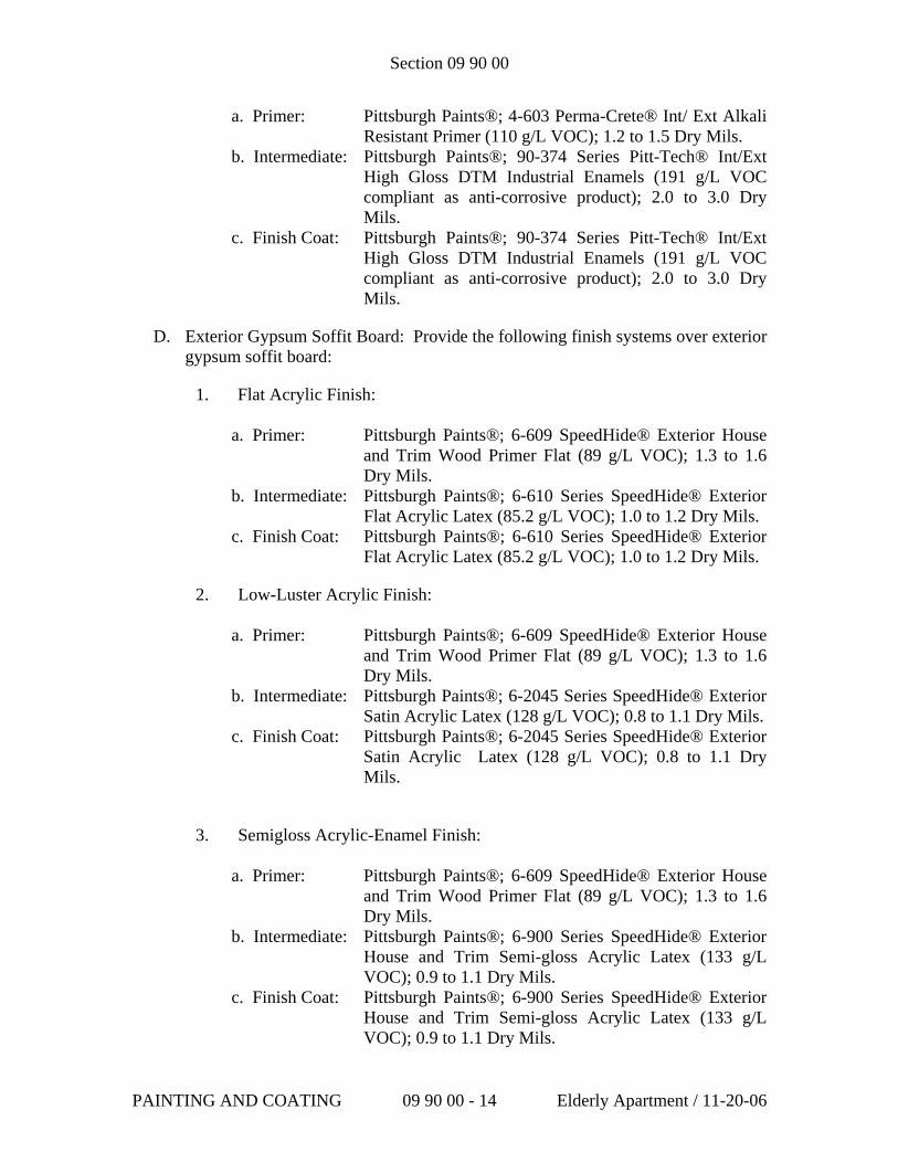
Section 09 90 00
a. Primer: Pittsburgh Paints®; 4-603 Perma-Crete® Int/ Ext Alkali Resistant Primer (110 g/L VOC); 1.2 to 1.5 Dry Mils.
b. Intermediate: Pittsburgh Paints®; 90-374 Series Pitt-Tech® Int/Ext High Gloss DTM Industrial Enamels (191 g/L VOC compliant as anti-corrosive product); 2.0 to 3.0 Dry Mils.
c. Finish Coat: Pittsburgh Paints®; 90-374 Series Pitt-Tech® Int/Ext High Gloss DTM Industrial Enamels (191 g/L VOC compliant as anti-corrosive product); 2.0 to 3.0 Dry Mils.
D. Exterior Gypsum Soffit Board: Provide the following finish systems over exterior gypsum soffit board:
1. Flat Acrylic Finish: a. Primer: Pittsburgh Paints®; 6-609 SpeedHide® Exterior House
and Trim Wood Primer Flat (89 g/L VOC); 1.3 to 1.6 Dry Mils.
b. Intermediate: Pittsburgh Paints®; 6-610 Series SpeedHide® Exterior Flat Acrylic Latex (85.2 g/L VOC); 1.0 to 1.2 Dry Mils.
c. Finish Coat: Pittsburgh Paints®; 6-610 Series SpeedHide® Exterior Flat Acrylic Latex (85.2 g/L VOC); 1.0 to 1.2 Dry Mils.
2. Low-Luster Acrylic Finish:
a. Primer: Pittsburgh Paints®; 6-609 SpeedHide® Exterior House and Trim Wood Primer Flat (89 g/L VOC); 1.3 to 1.6 Dry Mils.
b. Intermediate: Pittsburgh Paints®; 6-2045 Series SpeedHide® Exterior Satin Acrylic Latex (128 g/L VOC); 0.8 to 1.1 Dry Mils.
c. Finish Coat: Pittsburgh Paints®; 6-2045 Series SpeedHide® Exterior Satin Acrylic Latex (128 g/L VOC); 0.8 to 1.1 Dry Mils.
3. Semigloss Acrylic-Enamel Finish:
a. Primer: Pittsburgh Paints®; 6-609 SpeedHide® Exterior House and Trim Wood Primer Flat (89 g/L VOC); 1.3 to 1.6 Dry Mils.
b. Intermediate: Pittsburgh Paints®; 6-900 Series SpeedHide® Exterior House and Trim Semi-gloss Acrylic Latex (133 g/L VOC); 0.9 to 1.1 Dry Mils.
c. Finish Coat: Pittsburgh Paints®; 6-900 Series SpeedHide® Exterior House and Trim Semi-gloss Acrylic Latex (133 g/L VOC); 0.9 to 1.1 Dry Mils.
PAINTING AND COATING 09 90 00 - 14 Elderly Apartment / 11-20-06
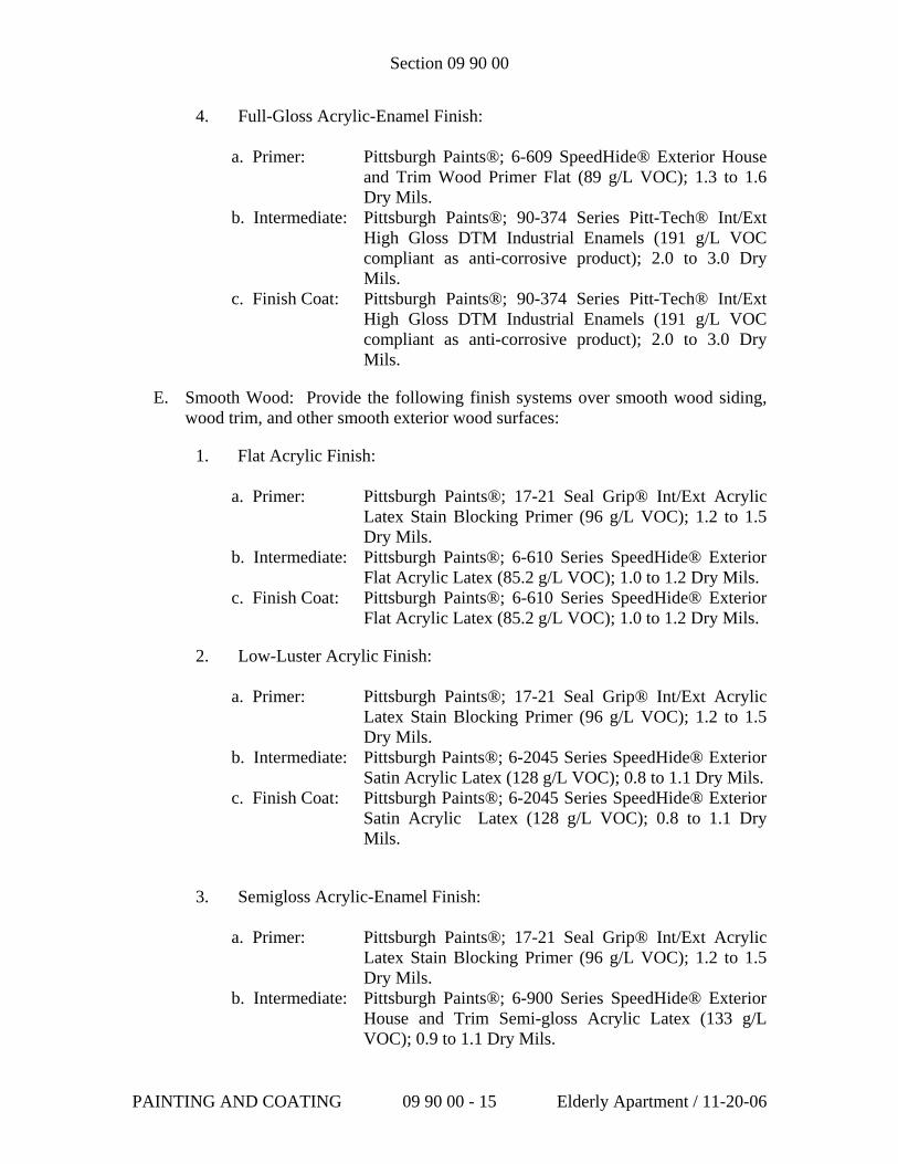
Section 09 90 00
4. Full-Gloss Acrylic-Enamel Finish:
a. Primer: Pittsburgh Paints®; 6-609 SpeedHide® Exterior House and Trim Wood Primer Flat (89 g/L VOC); 1.3 to 1.6 Dry Mils.
b. Intermediate: Pittsburgh Paints®; 90-374 Series Pitt-Tech® Int/Ext High Gloss DTM Industrial Enamels (191 g/L VOC compliant as anti-corrosive product); 2.0 to 3.0 Dry Mils.
c. Finish Coat: Pittsburgh Paints®; 90-374 Series Pitt-Tech® Int/Ext High Gloss DTM Industrial Enamels (191 g/L VOC compliant as anti-corrosive product); 2.0 to 3.0 Dry Mils.
E. Smooth Wood: Provide the following finish systems over smooth wood siding, wood trim, and other smooth exterior wood surfaces:
1. Flat Acrylic Finish: a. Primer: Pittsburgh Paints®; 17-21 Seal Grip® Int/Ext Acrylic
Latex Stain Blocking Primer (96 g/L VOC); 1.2 to 1.5 Dry Mils.
b. Intermediate: Pittsburgh Paints®; 6-610 Series SpeedHide® Exterior Flat Acrylic Latex (85.2 g/L VOC); 1.0 to 1.2 Dry Mils.
c. Finish Coat: Pittsburgh Paints®; 6-610 Series SpeedHide® Exterior Flat Acrylic Latex (85.2 g/L VOC); 1.0 to 1.2 Dry Mils.
2. Low-Luster Acrylic Finish:
a. Primer: Pittsburgh Paints®; 17-21 Seal Grip® Int/Ext Acrylic Latex Stain Blocking Primer (96 g/L VOC); 1.2 to 1.5 Dry Mils.
b. Intermediate: Pittsburgh Paints®; 6-2045 Series SpeedHide® Exterior Satin Acrylic Latex (128 g/L VOC); 0.8 to 1.1 Dry Mils.
c. Finish Coat: Pittsburgh Paints®; 6-2045 Series SpeedHide® Exterior Satin Acrylic Latex (128 g/L VOC); 0.8 to 1.1 Dry Mils.
3. Semigloss Acrylic-Enamel Finish:
a. Primer: Pittsburgh Paints®; 17-21 Seal Grip® Int/Ext Acrylic Latex Stain Blocking Primer (96 g/L VOC); 1.2 to 1.5 Dry Mils.
b. Intermediate: Pittsburgh Paints®; 6-900 Series SpeedHide® Exterior House and Trim Semi-gloss Acrylic Latex (133 g/L VOC); 0.9 to 1.1 Dry Mils.
PAINTING AND COATING 09 90 00 - 15 Elderly Apartment / 11-20-06
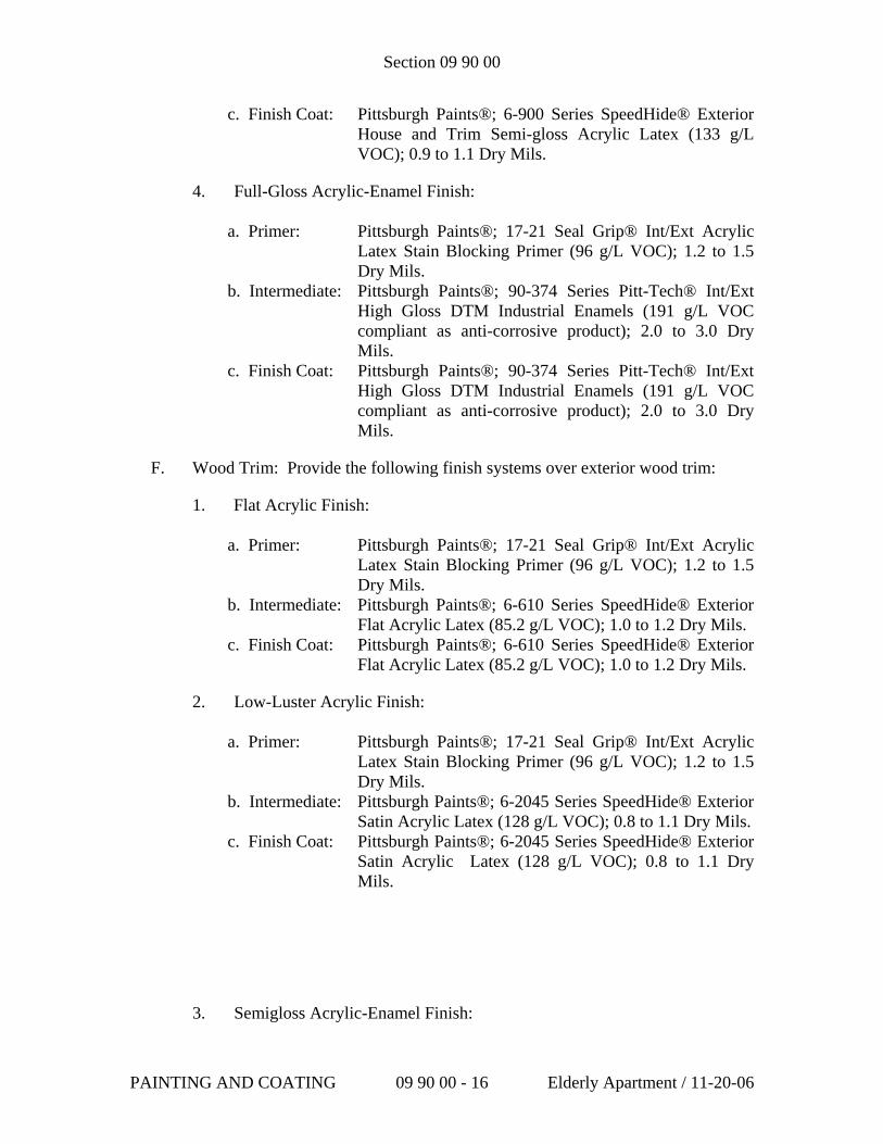
Section 09 90 00
c. Finish Coat: Pittsburgh Paints®; 6-900 Series SpeedHide® Exterior House and Trim Semi-gloss Acrylic Latex (133 g/L VOC); 0.9 to 1.1 Dry Mils.
4. Full-Gloss Acrylic-Enamel Finish:
a. Primer: Pittsburgh Paints®; 17-21 Seal Grip® Int/Ext Acrylic Latex Stain Blocking Primer (96 g/L VOC); 1.2 to 1.5 Dry Mils.
b. Intermediate: Pittsburgh Paints®; 90-374 Series Pitt-Tech® Int/Ext High Gloss DTM Industrial Enamels (191 g/L VOC compliant as anti-corrosive product); 2.0 to 3.0 Dry Mils.
c. Finish Coat: Pittsburgh Paints®; 90-374 Series Pitt-Tech® Int/Ext High Gloss DTM Industrial Enamels (191 g/L VOC compliant as anti-corrosive product); 2.0 to 3.0 Dry Mils.
F. Wood Trim: Provide the following finish systems over exterior wood trim:
1. Flat Acrylic Finish: a. Primer: Pittsburgh Paints®; 17-21 Seal Grip® Int/Ext Acrylic
Latex Stain Blocking Primer (96 g/L VOC); 1.2 to 1.5 Dry Mils.
b. Intermediate: Pittsburgh Paints®; 6-610 Series SpeedHide® Exterior Flat Acrylic Latex (85.2 g/L VOC); 1.0 to 1.2 Dry Mils.
c. Finish Coat: Pittsburgh Paints®; 6-610 Series SpeedHide® Exterior Flat Acrylic Latex (85.2 g/L VOC); 1.0 to 1.2 Dry Mils.
2. Low-Luster Acrylic Finish:
a. Primer: Pittsburgh Paints®; 17-21 Seal Grip® Int/Ext Acrylic Latex Stain Blocking Primer (96 g/L VOC); 1.2 to 1.5 Dry Mils.
b. Intermediate: Pittsburgh Paints®; 6-2045 Series SpeedHide® Exterior Satin Acrylic Latex (128 g/L VOC); 0.8 to 1.1 Dry Mils.
c. Finish Coat: Pittsburgh Paints®; 6-2045 Series SpeedHide® Exterior Satin Acrylic Latex (128 g/L VOC); 0.8 to 1.1 Dry Mils.
3. Semigloss Acrylic-Enamel Finish:
PAINTING AND COATING 09 90 00 - 16 Elderly Apartment / 11-20-06
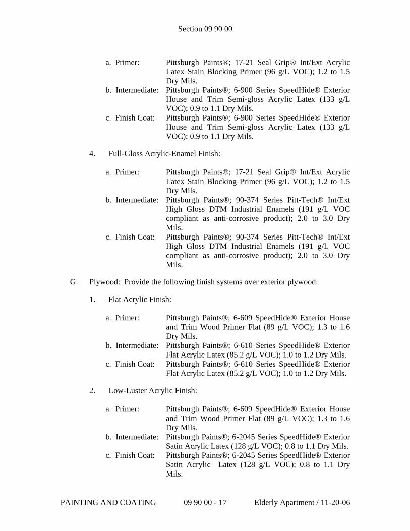
Section 09 90 00
a. Primer: Pittsburgh Paints®; 17-21 Seal Grip® Int/Ext Acrylic
Latex Stain Blocking Primer (96 g/L VOC); 1.2 to 1.5 Dry Mils.
b. Intermediate: Pittsburgh Paints®; 6-900 Series SpeedHide® Exterior House and Trim Semi-gloss Acrylic Latex (133 g/L VOC); 0.9 to 1.1 Dry Mils.
c. Finish Coat: Pittsburgh Paints®; 6-900 Series SpeedHide® Exterior House and Trim Semi-gloss Acrylic Latex (133 g/L VOC); 0.9 to 1.1 Dry Mils.
4. Full-Gloss Acrylic-Enamel Finish:
a. Primer: Pittsburgh Paints®; 17-21 Seal Grip® Int/Ext Acrylic Latex Stain Blocking Primer (96 g/L VOC); 1.2 to 1.5 Dry Mils.
b. Intermediate: Pittsburgh Paints®; 90-374 Series Pitt-Tech® Int/Ext High Gloss DTM Industrial Enamels (191 g/L VOC compliant as anti-corrosive product); 2.0 to 3.0 Dry Mils.
c. Finish Coat: Pittsburgh Paints®; 90-374 Series Pitt-Tech® Int/Ext High Gloss DTM Industrial Enamels (191 g/L VOC compliant as anti-corrosive product); 2.0 to 3.0 Dry Mils.
G. Plywood: Provide the following finish systems over exterior plywood:
1. Flat Acrylic Finish: a. Primer: Pittsburgh Paints®; 6-609 SpeedHide® Exterior House
and Trim Wood Primer Flat (89 g/L VOC); 1.3 to 1.6 Dry Mils.
b. Intermediate: Pittsburgh Paints®; 6-610 Series SpeedHide® Exterior Flat Acrylic Latex (85.2 g/L VOC); 1.0 to 1.2 Dry Mils.
c. Finish Coat: Pittsburgh Paints®; 6-610 Series SpeedHide® Exterior Flat Acrylic Latex (85.2 g/L VOC); 1.0 to 1.2 Dry Mils.
2. Low-Luster Acrylic Finish:
a. Primer: Pittsburgh Paints®; 6-609 SpeedHide® Exterior House and Trim Wood Primer Flat (89 g/L VOC); 1.3 to 1.6 Dry Mils.
b. Intermediate: Pittsburgh Paints®; 6-2045 Series SpeedHide® Exterior Satin Acrylic Latex (128 g/L VOC); 0.8 to 1.1 Dry Mils.
c. Finish Coat: Pittsburgh Paints®; 6-2045 Series SpeedHide® Exterior Satin Acrylic Latex (128 g/L VOC); 0.8 to 1.1 Dry Mils.
PAINTING AND COATING 09 90 00 - 17 Elderly Apartment / 11-20-06
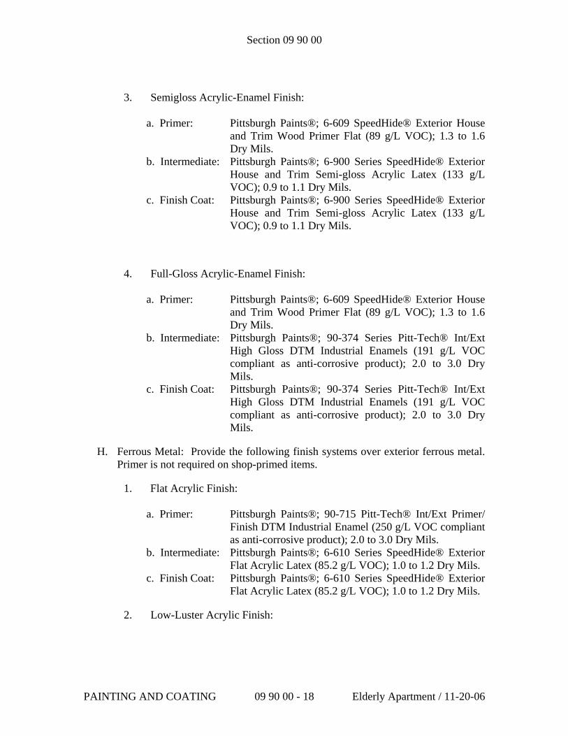
Section 09 90 00
3. Semigloss Acrylic-Enamel Finish:
a. Primer: Pittsburgh Paints®; 6-609 SpeedHide® Exterior House and Trim Wood Primer Flat (89 g/L VOC); 1.3 to 1.6 Dry Mils.
b. Intermediate: Pittsburgh Paints®; 6-900 Series SpeedHide® Exterior House and Trim Semi-gloss Acrylic Latex (133 g/L VOC); 0.9 to 1.1 Dry Mils.
c. Finish Coat: Pittsburgh Paints®; 6-900 Series SpeedHide® Exterior House and Trim Semi-gloss Acrylic Latex (133 g/L VOC); 0.9 to 1.1 Dry Mils.
4. Full-Gloss Acrylic-Enamel Finish:
a. Primer: Pittsburgh Paints®; 6-609 SpeedHide® Exterior House and Trim Wood Primer Flat (89 g/L VOC); 1.3 to 1.6 Dry Mils.
b. Intermediate: Pittsburgh Paints®; 90-374 Series Pitt-Tech® Int/Ext High Gloss DTM Industrial Enamels (191 g/L VOC compliant as anti-corrosive product); 2.0 to 3.0 Dry Mils.
c. Finish Coat: Pittsburgh Paints®; 90-374 Series Pitt-Tech® Int/Ext High Gloss DTM Industrial Enamels (191 g/L VOC compliant as anti-corrosive product); 2.0 to 3.0 Dry Mils.
H. Ferrous Metal: Provide the following finish systems over exterior ferrous metal. Primer is not required on shop-primed items.
1. Flat Acrylic Finish: a. Primer: Pittsburgh Paints®; 90-715 Pitt-Tech® Int/Ext Primer/
Finish DTM Industrial Enamel (250 g/L VOC compliant as anti-corrosive product); 2.0 to 3.0 Dry Mils.
b. Intermediate: Pittsburgh Paints®; 6-610 Series SpeedHide® Exterior Flat Acrylic Latex (85.2 g/L VOC); 1.0 to 1.2 Dry Mils.
c. Finish Coat: Pittsburgh Paints®; 6-610 Series SpeedHide® Exterior Flat Acrylic Latex (85.2 g/L VOC); 1.0 to 1.2 Dry Mils.
2. Low-Luster Acrylic Finish:
PAINTING AND COATING 09 90 00 - 18 Elderly Apartment / 11-20-06
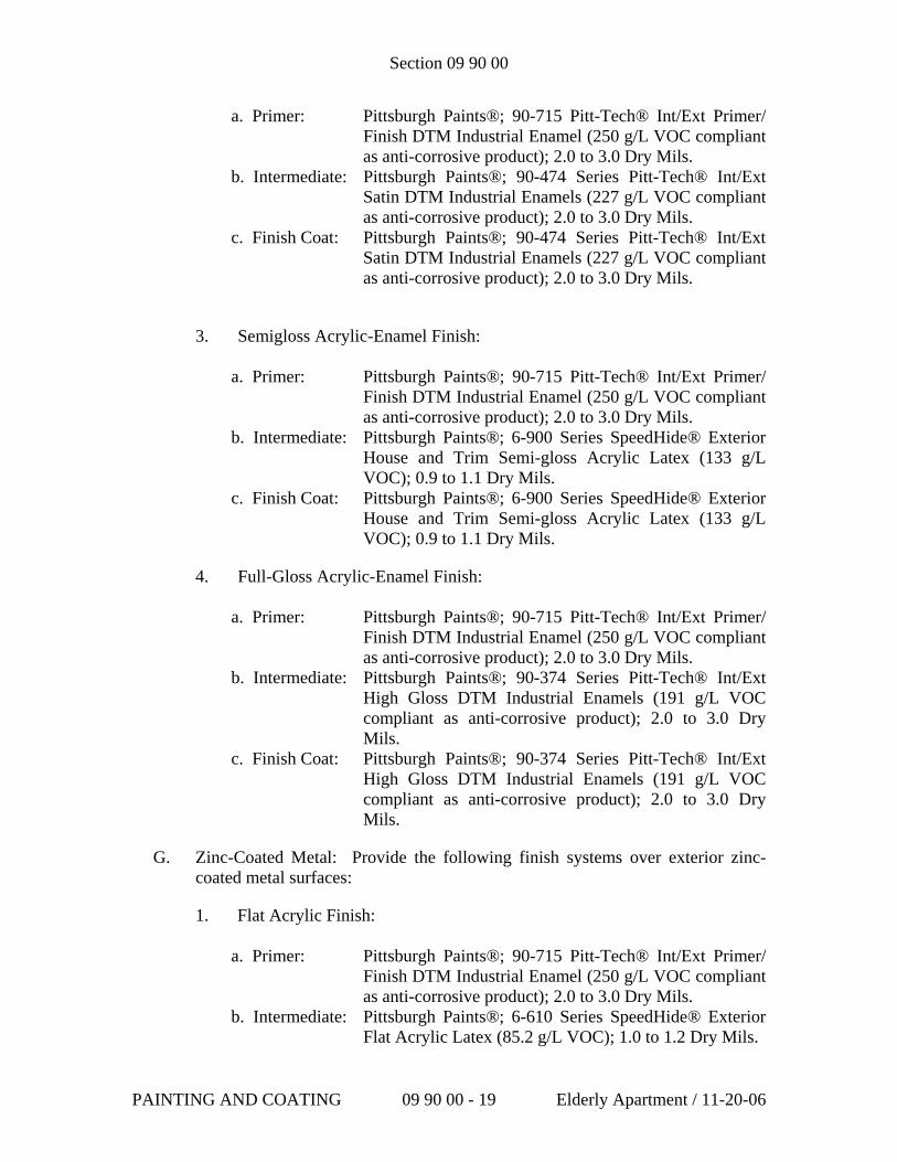
Section 09 90 00
a. Primer: Pittsburgh Paints®; 90-715 Pitt-Tech® Int/Ext Primer/ Finish DTM Industrial Enamel (250 g/L VOC compliant as anti-corrosive product); 2.0 to 3.0 Dry Mils.
b. Intermediate: Pittsburgh Paints®; 90-474 Series Pitt-Tech® Int/Ext Satin DTM Industrial Enamels (227 g/L VOC compliant as anti-corrosive product); 2.0 to 3.0 Dry Mils.
c. Finish Coat: Pittsburgh Paints®; 90-474 Series Pitt-Tech® Int/Ext Satin DTM Industrial Enamels (227 g/L VOC compliant as anti-corrosive product); 2.0 to 3.0 Dry Mils.
3. Semigloss Acrylic-Enamel Finish:
a. Primer: Pittsburgh Paints®; 90-715 Pitt-Tech® Int/Ext Primer/ Finish DTM Industrial Enamel (250 g/L VOC compliant as anti-corrosive product); 2.0 to 3.0 Dry Mils.
b. Intermediate: Pittsburgh Paints®; 6-900 Series SpeedHide® Exterior House and Trim Semi-gloss Acrylic Latex (133 g/L VOC); 0.9 to 1.1 Dry Mils.
c. Finish Coat: Pittsburgh Paints®; 6-900 Series SpeedHide® Exterior House and Trim Semi-gloss Acrylic Latex (133 g/L VOC); 0.9 to 1.1 Dry Mils.
4. Full-Gloss Acrylic-Enamel Finish:
a. Primer: Pittsburgh Paints®; 90-715 Pitt-Tech® Int/Ext Primer/ Finish DTM Industrial Enamel (250 g/L VOC compliant as anti-corrosive product); 2.0 to 3.0 Dry Mils.
b. Intermediate: Pittsburgh Paints®; 90-374 Series Pitt-Tech® Int/Ext High Gloss DTM Industrial Enamels (191 g/L VOC compliant as anti-corrosive product); 2.0 to 3.0 Dry Mils.
c. Finish Coat: Pittsburgh Paints®; 90-374 Series Pitt-Tech® Int/Ext High Gloss DTM Industrial Enamels (191 g/L VOC compliant as anti-corrosive product); 2.0 to 3.0 Dry Mils.
G. Zinc-Coated Metal: Provide the following finish systems over exterior zinc-coated metal surfaces:
1. Flat Acrylic Finish: a. Primer: Pittsburgh Paints®; 90-715 Pitt-Tech® Int/Ext Primer/
Finish DTM Industrial Enamel (250 g/L VOC compliant as anti-corrosive product); 2.0 to 3.0 Dry Mils.
b. Intermediate: Pittsburgh Paints®; 6-610 Series SpeedHide® Exterior Flat Acrylic Latex (85.2 g/L VOC); 1.0 to 1.2 Dry Mils.
PAINTING AND COATING 09 90 00 - 19 Elderly Apartment / 11-20-06
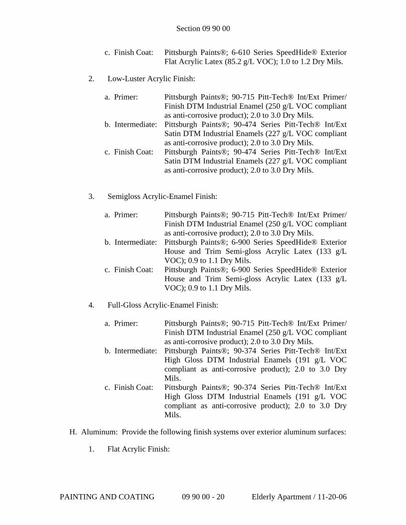
Section 09 90 00
c. Finish Coat: Pittsburgh Paints®; 6-610 Series SpeedHide® Exterior Flat Acrylic Latex (85.2 g/L VOC); 1.0 to 1.2 Dry Mils.
2. Low-Luster Acrylic Finish:
a. Primer: Pittsburgh Paints®; 90-715 Pitt-Tech® Int/Ext Primer/ Finish DTM Industrial Enamel (250 g/L VOC compliant as anti-corrosive product); 2.0 to 3.0 Dry Mils.
b. Intermediate: Pittsburgh Paints®; 90-474 Series Pitt-Tech® Int/Ext Satin DTM Industrial Enamels (227 g/L VOC compliant as anti-corrosive product); 2.0 to 3.0 Dry Mils.
c. Finish Coat: Pittsburgh Paints®; 90-474 Series Pitt-Tech® Int/Ext Satin DTM Industrial Enamels (227 g/L VOC compliant as anti-corrosive product); 2.0 to 3.0 Dry Mils.
3. Semigloss Acrylic-Enamel Finish:
a. Primer: Pittsburgh Paints®; 90-715 Pitt-Tech® Int/Ext Primer/ Finish DTM Industrial Enamel (250 g/L VOC compliant as anti-corrosive product); 2.0 to 3.0 Dry Mils.
b. Intermediate: Pittsburgh Paints®; 6-900 Series SpeedHide® Exterior House and Trim Semi-gloss Acrylic Latex (133 g/L VOC); 0.9 to 1.1 Dry Mils.
c. Finish Coat: Pittsburgh Paints®; 6-900 Series SpeedHide® Exterior House and Trim Semi-gloss Acrylic Latex (133 g/L VOC); 0.9 to 1.1 Dry Mils.
4. Full-Gloss Acrylic-Enamel Finish:
a. Primer: Pittsburgh Paints®; 90-715 Pitt-Tech® Int/Ext Primer/ Finish DTM Industrial Enamel (250 g/L VOC compliant as anti-corrosive product); 2.0 to 3.0 Dry Mils.
b. Intermediate: Pittsburgh Paints®; 90-374 Series Pitt-Tech® Int/Ext High Gloss DTM Industrial Enamels (191 g/L VOC compliant as anti-corrosive product); 2.0 to 3.0 Dry Mils.
c. Finish Coat: Pittsburgh Paints®; 90-374 Series Pitt-Tech® Int/Ext High Gloss DTM Industrial Enamels (191 g/L VOC compliant as anti-corrosive product); 2.0 to 3.0 Dry Mils.
H. Aluminum: Provide the following finish systems over exterior aluminum surfaces:
1. Flat Acrylic Finish:
PAINTING AND COATING 09 90 00 - 20 Elderly Apartment / 11-20-06
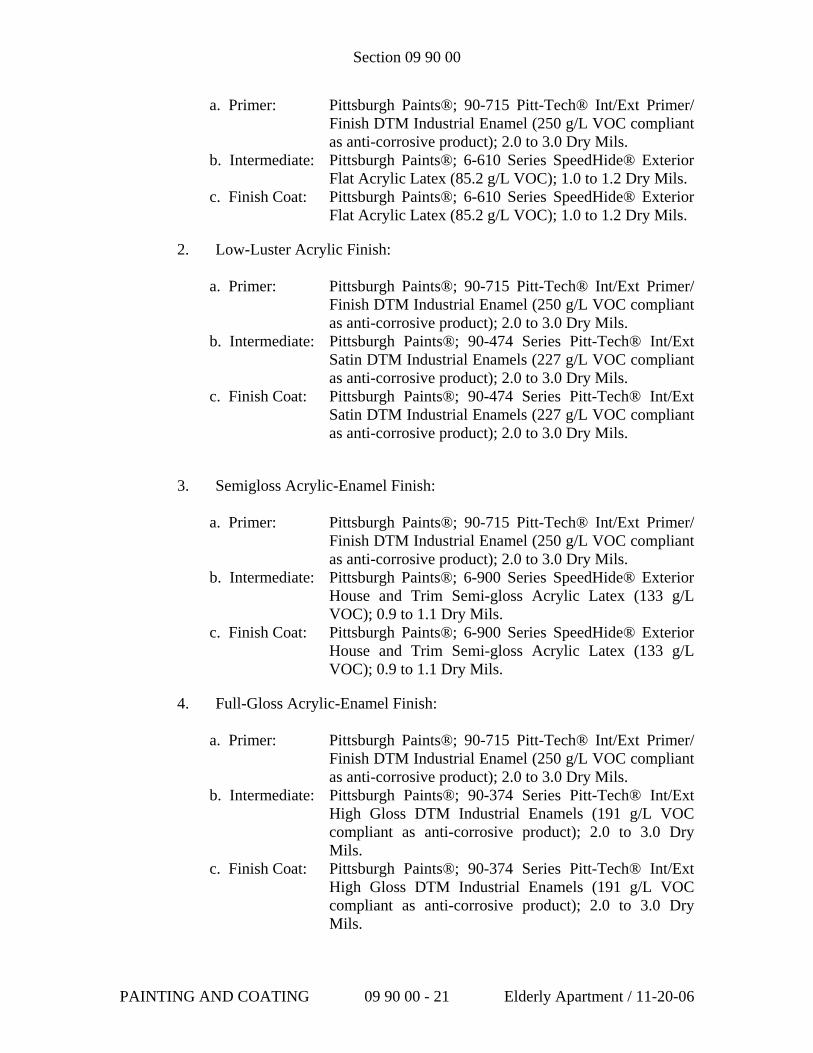
Section 09 90 00
a. Primer: Pittsburgh Paints®; 90-715 Pitt-Tech® Int/Ext Primer/ Finish DTM Industrial Enamel (250 g/L VOC compliant as anti-corrosive product); 2.0 to 3.0 Dry Mils.
b. Intermediate: Pittsburgh Paints®; 6-610 Series SpeedHide® Exterior Flat Acrylic Latex (85.2 g/L VOC); 1.0 to 1.2 Dry Mils.
c. Finish Coat: Pittsburgh Paints®; 6-610 Series SpeedHide® Exterior Flat Acrylic Latex (85.2 g/L VOC); 1.0 to 1.2 Dry Mils.
2. Low-Luster Acrylic Finish:
a. Primer: Pittsburgh Paints®; 90-715 Pitt-Tech® Int/Ext Primer/ Finish DTM Industrial Enamel (250 g/L VOC compliant as anti-corrosive product); 2.0 to 3.0 Dry Mils.
b. Intermediate: Pittsburgh Paints®; 90-474 Series Pitt-Tech® Int/Ext Satin DTM Industrial Enamels (227 g/L VOC compliant as anti-corrosive product); 2.0 to 3.0 Dry Mils.
c. Finish Coat: Pittsburgh Paints®; 90-474 Series Pitt-Tech® Int/Ext Satin DTM Industrial Enamels (227 g/L VOC compliant as anti-corrosive product); 2.0 to 3.0 Dry Mils.
3. Semigloss Acrylic-Enamel Finish:
a. Primer: Pittsburgh Paints®; 90-715 Pitt-Tech® Int/Ext Primer/ Finish DTM Industrial Enamel (250 g/L VOC compliant as anti-corrosive product); 2.0 to 3.0 Dry Mils.
b. Intermediate: Pittsburgh Paints®; 6-900 Series SpeedHide® Exterior House and Trim Semi-gloss Acrylic Latex (133 g/L VOC); 0.9 to 1.1 Dry Mils.
c. Finish Coat: Pittsburgh Paints®; 6-900 Series SpeedHide® Exterior House and Trim Semi-gloss Acrylic Latex (133 g/L VOC); 0.9 to 1.1 Dry Mils.
4. Full-Gloss Acrylic-Enamel Finish:
a. Primer: Pittsburgh Paints®; 90-715 Pitt-Tech® Int/Ext Primer/ Finish DTM Industrial Enamel (250 g/L VOC compliant as anti-corrosive product); 2.0 to 3.0 Dry Mils.
b. Intermediate: Pittsburgh Paints®; 90-374 Series Pitt-Tech® Int/Ext High Gloss DTM Industrial Enamels (191 g/L VOC compliant as anti-corrosive product); 2.0 to 3.0 Dry Mils.
c. Finish Coat: Pittsburgh Paints®; 90-374 Series Pitt-Tech® Int/Ext High Gloss DTM Industrial Enamels (191 g/L VOC compliant as anti-corrosive product); 2.0 to 3.0 Dry Mils.
PAINTING AND COATING 09 90 00 - 21 Elderly Apartment / 11-20-06
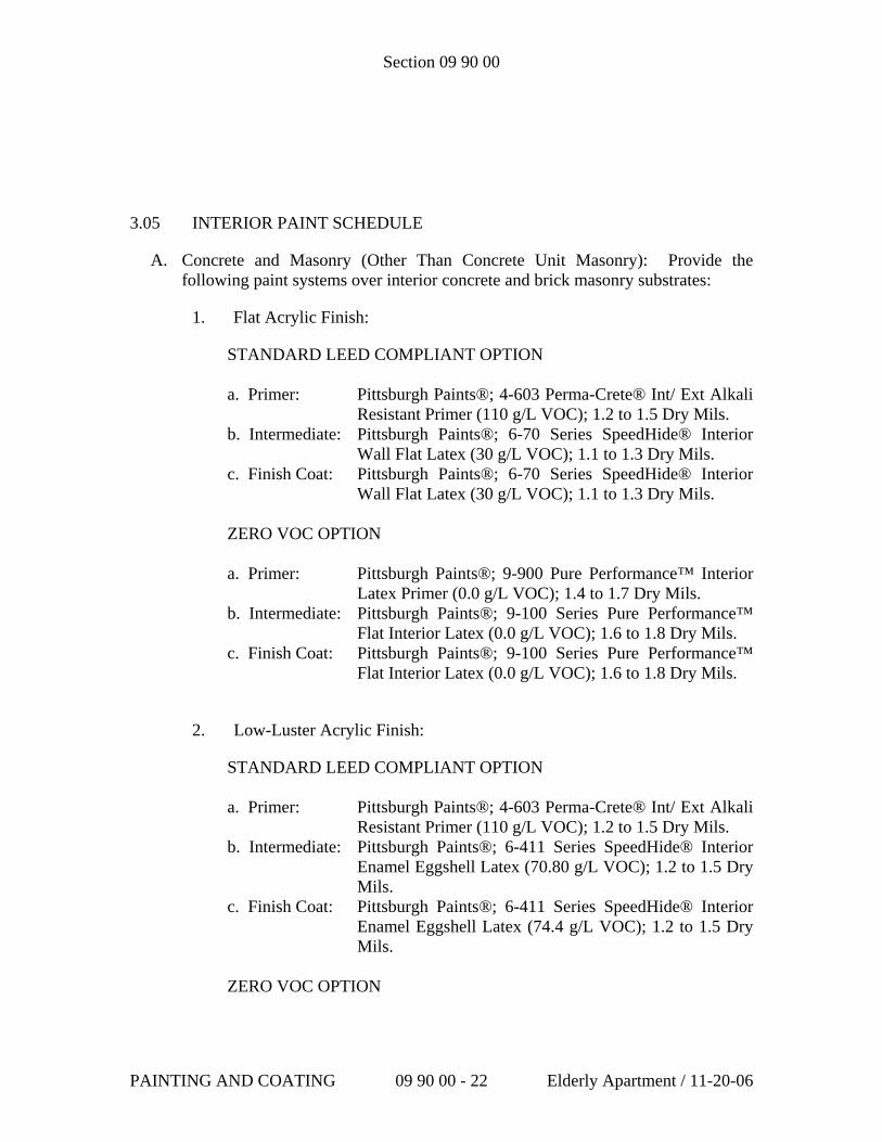
Section 09 90 00
3.05 INTERIOR PAINT SCHEDULE
A. Concrete and Masonry (Other Than Concrete Unit Masonry): Provide the following paint systems over interior concrete and brick masonry substrates:
1. Flat Acrylic Finish:
STANDARD LEED COMPLIANT OPTION a. Primer: Pittsburgh Paints®; 4-603 Perma-Crete® Int/ Ext Alkali
Resistant Primer (110 g/L VOC); 1.2 to 1.5 Dry Mils. b. Intermediate: Pittsburgh Paints®; 6-70 Series SpeedHide® Interior
Wall Flat Latex (30 g/L VOC); 1.1 to 1.3 Dry Mils. c. Finish Coat: Pittsburgh Paints®; 6-70 Series SpeedHide® Interior
Wall Flat Latex (30 g/L VOC); 1.1 to 1.3 Dry Mils. ZERO VOC OPTION a. Primer: Pittsburgh Paints®; 9-900 Pure Performance™ Interior
Latex Primer (0.0 g/L VOC); 1.4 to 1.7 Dry Mils. b. Intermediate: Pittsburgh Paints®; 9-100 Series Pure Performance™
Flat Interior Latex (0.0 g/L VOC); 1.6 to 1.8 Dry Mils. c. Finish Coat: Pittsburgh Paints®; 9-100 Series Pure Performance™
Flat Interior Latex (0.0 g/L VOC); 1.6 to 1.8 Dry Mils.
2. Low-Luster Acrylic Finish:
STANDARD LEED COMPLIANT OPTION
a. Primer: Pittsburgh Paints®; 4-603 Perma-Crete® Int/ Ext Alkali Resistant Primer (110 g/L VOC); 1.2 to 1.5 Dry Mils.
b. Intermediate: Pittsburgh Paints®; 6-411 Series SpeedHide® Interior Enamel Eggshell Latex (70.80 g/L VOC); 1.2 to 1.5 Dry Mils.
c. Finish Coat: Pittsburgh Paints®; 6-411 Series SpeedHide® Interior Enamel Eggshell Latex (74.4 g/L VOC); 1.2 to 1.5 Dry Mils.
ZERO VOC OPTION
PAINTING AND COATING 09 90 00 - 22 Elderly Apartment / 11-20-06
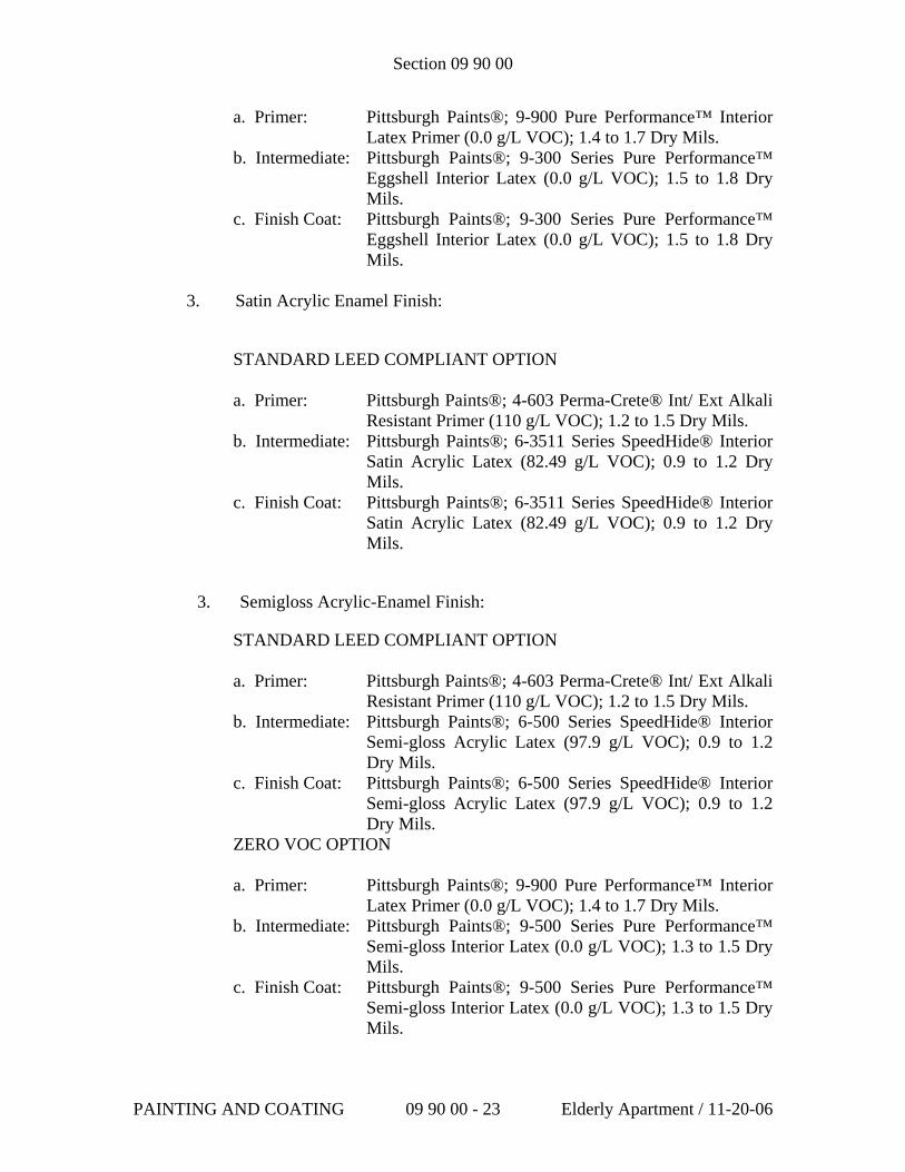
Section 09 90 00
a. Primer: Pittsburgh Paints®; 9-900 Pure Performance™ Interior Latex Primer (0.0 g/L VOC); 1.4 to 1.7 Dry Mils.
b. Intermediate: Pittsburgh Paints®; 9-300 Series Pure Performance™ Eggshell Interior Latex (0.0 g/L VOC); 1.5 to 1.8 Dry Mils.
c. Finish Coat: Pittsburgh Paints®; 9-300 Series Pure Performance™ Eggshell Interior Latex (0.0 g/L VOC); 1.5 to 1.8 Dry Mils.
3. Satin Acrylic Enamel Finish:
STANDARD LEED COMPLIANT OPTION
a. Primer: Pittsburgh Paints®; 4-603 Perma-Crete® Int/ Ext Alkali Resistant Primer (110 g/L VOC); 1.2 to 1.5 Dry Mils.
b. Intermediate: Pittsburgh Paints®; 6-3511 Series SpeedHide® Interior Satin Acrylic Latex (82.49 g/L VOC); 0.9 to 1.2 Dry Mils.
c. Finish Coat: Pittsburgh Paints®; 6-3511 Series SpeedHide® Interior Satin Acrylic Latex (82.49 g/L VOC); 0.9 to 1.2 Dry Mils.
3. Semigloss Acrylic-Enamel Finish:
STANDARD LEED COMPLIANT OPTION
a. Primer: Pittsburgh Paints®; 4-603 Perma-Crete® Int/ Ext Alkali Resistant Primer (110 g/L VOC); 1.2 to 1.5 Dry Mils.
b. Intermediate: Pittsburgh Paints®; 6-500 Series SpeedHide® Interior Semi-gloss Acrylic Latex (97.9 g/L VOC); 0.9 to 1.2 Dry Mils.
c. Finish Coat: Pittsburgh Paints®; 6-500 Series SpeedHide® Interior Semi-gloss Acrylic Latex (97.9 g/L VOC); 0.9 to 1.2 Dry Mils.
ZERO VOC OPTION
a. Primer: Pittsburgh Paints®; 9-900 Pure Performance™ Interior Latex Primer (0.0 g/L VOC); 1.4 to 1.7 Dry Mils.
b. Intermediate: Pittsburgh Paints®; 9-500 Series Pure Performance™ Semi-gloss Interior Latex (0.0 g/L VOC); 1.3 to 1.5 Dry Mils.
c. Finish Coat: Pittsburgh Paints®; 9-500 Series Pure Performance™ Semi-gloss Interior Latex (0.0 g/L VOC); 1.3 to 1.5 Dry Mils.
PAINTING AND COATING 09 90 00 - 23 Elderly Apartment / 11-20-06
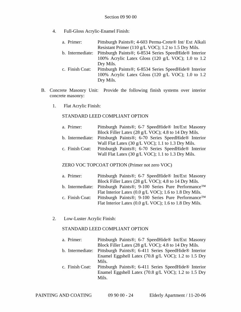
Section 09 90 00
4. Full-Gloss Acrylic-Enamel Finish:
a. Primer: Pittsburgh Paints®; 4-603 Perma-Crete® Int/ Ext Alkali Resistant Primer (110 g/L VOC); 1.2 to 1.5 Dry Mils.
b. Intermediate: Pittsburgh Paints®; 6-8534 Series SpeedHide® Interior 100% Acrylic Latex Gloss (120 g/L VOC); 1.0 to 1.2 Dry Mils.
c. Finish Coat: Pittsburgh Paints®; 6-8534 Series SpeedHide® Interior 100% Acrylic Latex Gloss (120 g/L VOC); 1.0 to 1.2 Dry Mils.
B. Concrete Masonry Unit: Provide the following finish systems over interior concrete masonry:
1. Flat Acrylic Finish:
STANDARD LEED COMPLIANT OPTION a. Primer: Pittsburgh Paints®; 6-7 SpeedHide® Int/Ext Masonry
Block Filler Latex (28 g/L VOC); 4.8 to 14 Dry Mils. b. Intermediate: Pittsburgh Paints®; 6-70 Series SpeedHide® Interior
Wall Flat Latex (30 g/L VOC); 1.1 to 1.3 Dry Mils. c. Finish Coat: Pittsburgh Paints®; 6-70 Series SpeedHide® Interior
Wall Flat Latex (30 g/L VOC); 1.1 to 1.3 Dry Mils. ZERO VOC TOPCOAT OPTION (Primer not zero VOC) a. Primer: Pittsburgh Paints®; 6-7 SpeedHide® Int/Ext Masonry
Block Filler Latex (28 g/L VOC); 4.8 to 14 Dry Mils. b. Intermediate: Pittsburgh Paints®; 9-100 Series Pure Performance™
Flat Interior Latex (0.0 g/L VOC); 1.6 to 1.8 Dry Mils. c. Finish Coat: Pittsburgh Paints®; 9-100 Series Pure Performance™
Flat Interior Latex (0.0 g/L VOC); 1.6 to 1.8 Dry Mils.
2. Low-Luster Acrylic Finish:
STANDARD LEED COMPLIANT OPTION
a. Primer: Pittsburgh Paints®; 6-7 SpeedHide® Int/Ext Masonry Block Filler Latex (28 g/L VOC); 4.8 to 14 Dry Mils.
b. Intermediate: Pittsburgh Paints®; 6-411 Series SpeedHide® Interior Enamel Eggshell Latex (70.8 g/L VOC); 1.2 to 1.5 Dry Mils.
c. Finish Coat: Pittsburgh Paints®; 6-411 Series SpeedHide® Interior Enamel Eggshell Latex (70.8 g/L VOC); 1.2 to 1.5 Dry Mils.
PAINTING AND COATING 09 90 00 - 24 Elderly Apartment / 11-20-06
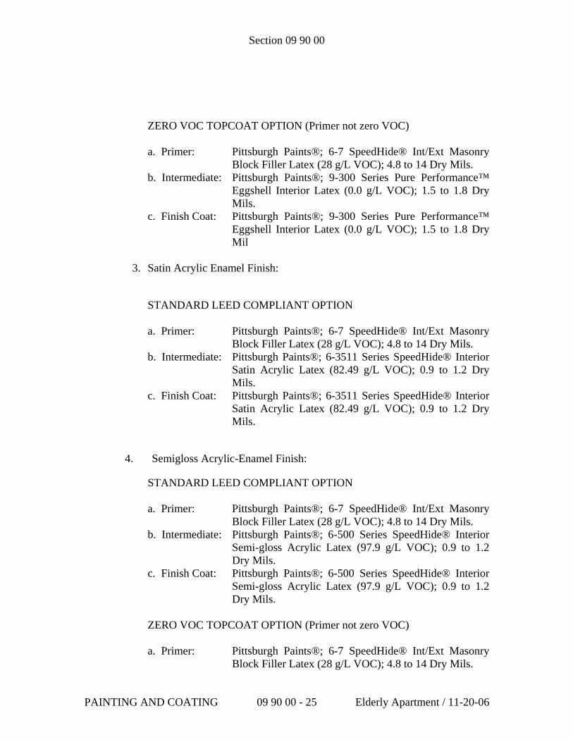
Section 09 90 00
ZERO VOC TOPCOAT OPTION (Primer not zero VOC) a. Primer: Pittsburgh Paints®; 6-7 SpeedHide® Int/Ext Masonry
Block Filler Latex (28 g/L VOC); 4.8 to 14 Dry Mils. b. Intermediate: Pittsburgh Paints®; 9-300 Series Pure Performance™
Eggshell Interior Latex (0.0 g/L VOC); 1.5 to 1.8 Dry Mils.
c. Finish Coat: Pittsburgh Paints®; 9-300 Series Pure Performance™ Eggshell Interior Latex (0.0 g/L VOC); 1.5 to 1.8 Dry Mil
3. Satin Acrylic Enamel Finish:
STANDARD LEED COMPLIANT OPTION
a. Primer: Pittsburgh Paints®; 6-7 SpeedHide® Int/Ext Masonry Block Filler Latex (28 g/L VOC); 4.8 to 14 Dry Mils.
b. Intermediate: Pittsburgh Paints®; 6-3511 Series SpeedHide® Interior Satin Acrylic Latex (82.49 g/L VOC); 0.9 to 1.2 Dry Mils.
c. Finish Coat: Pittsburgh Paints®; 6-3511 Series SpeedHide® Interior Satin Acrylic Latex (82.49 g/L VOC); 0.9 to 1.2 Dry Mils.
4. Semigloss Acrylic-Enamel Finish:
STANDARD LEED COMPLIANT OPTION
a. Primer: Pittsburgh Paints®; 6-7 SpeedHide® Int/Ext Masonry Block Filler Latex (28 g/L VOC); 4.8 to 14 Dry Mils.
b. Intermediate: Pittsburgh Paints®; 6-500 Series SpeedHide® Interior Semi-gloss Acrylic Latex (97.9 g/L VOC); 0.9 to 1.2 Dry Mils.
c. Finish Coat: Pittsburgh Paints®; 6-500 Series SpeedHide® Interior Semi-gloss Acrylic Latex (97.9 g/L VOC); 0.9 to 1.2 Dry Mils.
ZERO VOC TOPCOAT OPTION (Primer not zero VOC)
a. Primer: Pittsburgh Paints®; 6-7 SpeedHide® Int/Ext Masonry Block Filler Latex (28 g/L VOC); 4.8 to 14 Dry Mils.
PAINTING AND COATING 09 90 00 - 25 Elderly Apartment / 11-20-06
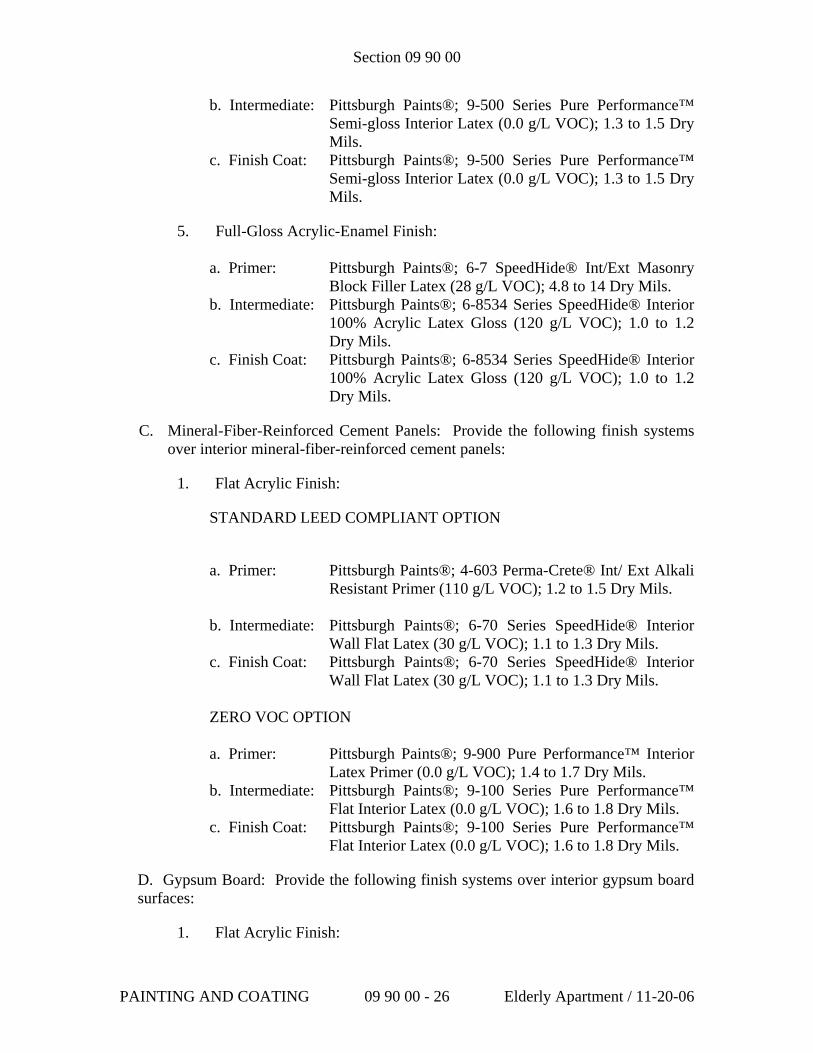
Section 09 90 00
b. Intermediate: Pittsburgh Paints®; 9-500 Series Pure Performance™ Semi-gloss Interior Latex (0.0 g/L VOC); 1.3 to 1.5 Dry Mils.
c. Finish Coat: Pittsburgh Paints®; 9-500 Series Pure Performance™ Semi-gloss Interior Latex (0.0 g/L VOC); 1.3 to 1.5 Dry Mils.
5. Full-Gloss Acrylic-Enamel Finish:
a. Primer: Pittsburgh Paints®; 6-7 SpeedHide® Int/Ext Masonry Block Filler Latex (28 g/L VOC); 4.8 to 14 Dry Mils.
b. Intermediate: Pittsburgh Paints®; 6-8534 Series SpeedHide® Interior 100% Acrylic Latex Gloss (120 g/L VOC); 1.0 to 1.2 Dry Mils.
c. Finish Coat: Pittsburgh Paints®; 6-8534 Series SpeedHide® Interior 100% Acrylic Latex Gloss (120 g/L VOC); 1.0 to 1.2 Dry Mils.
C. Mineral-Fiber-Reinforced Cement Panels: Provide the following finish systems over interior mineral-fiber-reinforced cement panels:
1. Flat Acrylic Finish:
STANDARD LEED COMPLIANT OPTION
a. Primer: Pittsburgh Paints®; 4-603 Perma-Crete® Int/ Ext Alkali
Resistant Primer (110 g/L VOC); 1.2 to 1.5 Dry Mils. b. Intermediate: Pittsburgh Paints®; 6-70 Series SpeedHide® Interior
Wall Flat Latex (30 g/L VOC); 1.1 to 1.3 Dry Mils. c. Finish Coat: Pittsburgh Paints®; 6-70 Series SpeedHide® Interior
Wall Flat Latex (30 g/L VOC); 1.1 to 1.3 Dry Mils. ZERO VOC OPTION a. Primer: Pittsburgh Paints®; 9-900 Pure Performance™ Interior
Latex Primer (0.0 g/L VOC); 1.4 to 1.7 Dry Mils. b. Intermediate: Pittsburgh Paints®; 9-100 Series Pure Performance™
Flat Interior Latex (0.0 g/L VOC); 1.6 to 1.8 Dry Mils. c. Finish Coat: Pittsburgh Paints®; 9-100 Series Pure Performance™
Flat Interior Latex (0.0 g/L VOC); 1.6 to 1.8 Dry Mils.
D. Gypsum Board: Provide the following finish systems over interior gypsum board surfaces:
1. Flat Acrylic Finish:
PAINTING AND COATING 09 90 00 - 26 Elderly Apartment / 11-20-06
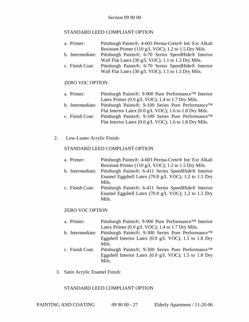
Section 09 90 00
STANDARD LEED COMPLIANT OPTION a. Primer: Pittsburgh Paints®; 4-603 Perma-Crete® Int/ Ext Alkali
Resistant Primer (110 g/L VOC); 1.2 to 1.5 Dry Mils. b. Intermediate: Pittsburgh Paints®; 6-70 Series SpeedHide® Interior
Wall Flat Latex (30 g/L VOC); 1.1 to 1.3 Dry Mils. c. Finish Coat: Pittsburgh Paints®; 6-70 Series SpeedHide® Interior
Wall Flat Latex (30 g/L VOC); 1.1 to 1.3 Dry Mils. ZERO VOC OPTION a. Primer: Pittsburgh Paints®; 9-900 Pure Performance™ Interior
Latex Primer (0.0 g/L VOC); 1.4 to 1.7 Dry Mils. b. Intermediate: Pittsburgh Paints®; 9-100 Series Pure Performance™
Flat Interior Latex (0.0 g/L VOC); 1.6 to 1.8 Dry Mils. c. Finish Coat: Pittsburgh Paints®; 9-100 Series Pure Performance™
Flat Interior Latex (0.0 g/L VOC); 1.6 to 1.8 Dry Mils.
2. Low-Luster Acrylic Finish:
STANDARD LEED COMPLIANT OPTION
a. Primer: Pittsburgh Paints®; 4-603 Perma-Crete® Int/ Ext Alkali Resistant Primer (110 g/L VOC); 1.2 to 1.5 Dry Mils.
b. Intermediate: Pittsburgh Paints®; 6-411 Series SpeedHide® Interior Enamel Eggshell Latex (70.8 g/L VOC); 1.2 to 1.5 Dry Mils.
c. Finish Coat: Pittsburgh Paints®; 6-411 Series SpeedHide® Interior Enamel Eggshell Latex (70.8 g/L VOC); 1.2 to 1.5 Dry Mils.
ZERO VOC OPTION a. Primer: Pittsburgh Paints®; 9-900 Pure Performance™ Interior
Latex Primer (0.0 g/L VOC); 1.4 to 1.7 Dry Mils. b. Intermediate: Pittsburgh Paints®; 9-300 Series Pure Performance™
Eggshell Interior Latex (0.0 g/L VOC); 1.5 to 1.8 Dry Mils.
c. Finish Coat: Pittsburgh Paints®; 9-300 Series Pure Performance™ Eggshell Interior Latex (0.0 g/L VOC); 1.5 to 1.8 Dry Mils.
3. Satin Acrylic Enamel Finish:
STANDARD LEED COMPLIANT OPTION
PAINTING AND COATING 09 90 00 - 27 Elderly Apartment / 11-20-06
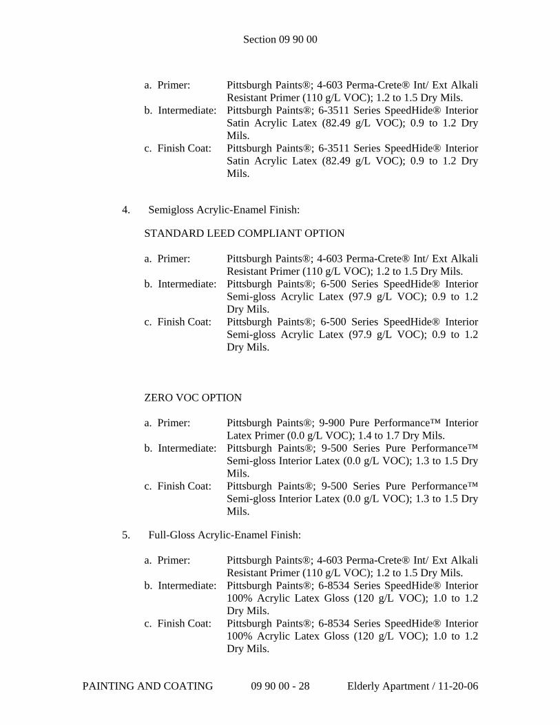
Section 09 90 00
a. Primer: Pittsburgh Paints®; 4-603 Perma-Crete® Int/ Ext Alkali
Resistant Primer (110 g/L VOC); 1.2 to 1.5 Dry Mils. b. Intermediate: Pittsburgh Paints®; 6-3511 Series SpeedHide® Interior
Satin Acrylic Latex (82.49 g/L VOC); 0.9 to 1.2 Dry Mils.
c. Finish Coat: Pittsburgh Paints®; 6-3511 Series SpeedHide® Interior Satin Acrylic Latex (82.49 g/L VOC); 0.9 to 1.2 Dry Mils.
4. Semigloss Acrylic-Enamel Finish:
STANDARD LEED COMPLIANT OPTION
a. Primer: Pittsburgh Paints®; 4-603 Perma-Crete® Int/ Ext Alkali Resistant Primer (110 g/L VOC); 1.2 to 1.5 Dry Mils.
b. Intermediate: Pittsburgh Paints®; 6-500 Series SpeedHide® Interior Semi-gloss Acrylic Latex (97.9 g/L VOC); 0.9 to 1.2 Dry Mils.
c. Finish Coat: Pittsburgh Paints®; 6-500 Series SpeedHide® Interior Semi-gloss Acrylic Latex (97.9 g/L VOC); 0.9 to 1.2 Dry Mils.
ZERO VOC OPTION
a. Primer: Pittsburgh Paints®; 9-900 Pure Performance™ Interior Latex Primer (0.0 g/L VOC); 1.4 to 1.7 Dry Mils.
b. Intermediate: Pittsburgh Paints®; 9-500 Series Pure Performance™ Semi-gloss Interior Latex (0.0 g/L VOC); 1.3 to 1.5 Dry Mils.
c. Finish Coat: Pittsburgh Paints®; 9-500 Series Pure Performance™ Semi-gloss Interior Latex (0.0 g/L VOC); 1.3 to 1.5 Dry Mils.
5. Full-Gloss Acrylic-Enamel Finish:
a. Primer: Pittsburgh Paints®; 4-603 Perma-Crete® Int/ Ext Alkali Resistant Primer (110 g/L VOC); 1.2 to 1.5 Dry Mils.
b. Intermediate: Pittsburgh Paints®; 6-8534 Series SpeedHide® Interior 100% Acrylic Latex Gloss (120 g/L VOC); 1.0 to 1.2 Dry Mils.
c. Finish Coat: Pittsburgh Paints®; 6-8534 Series SpeedHide® Interior 100% Acrylic Latex Gloss (120 g/L VOC); 1.0 to 1.2 Dry Mils.
PAINTING AND COATING 09 90 00 - 28 Elderly Apartment / 11-20-06
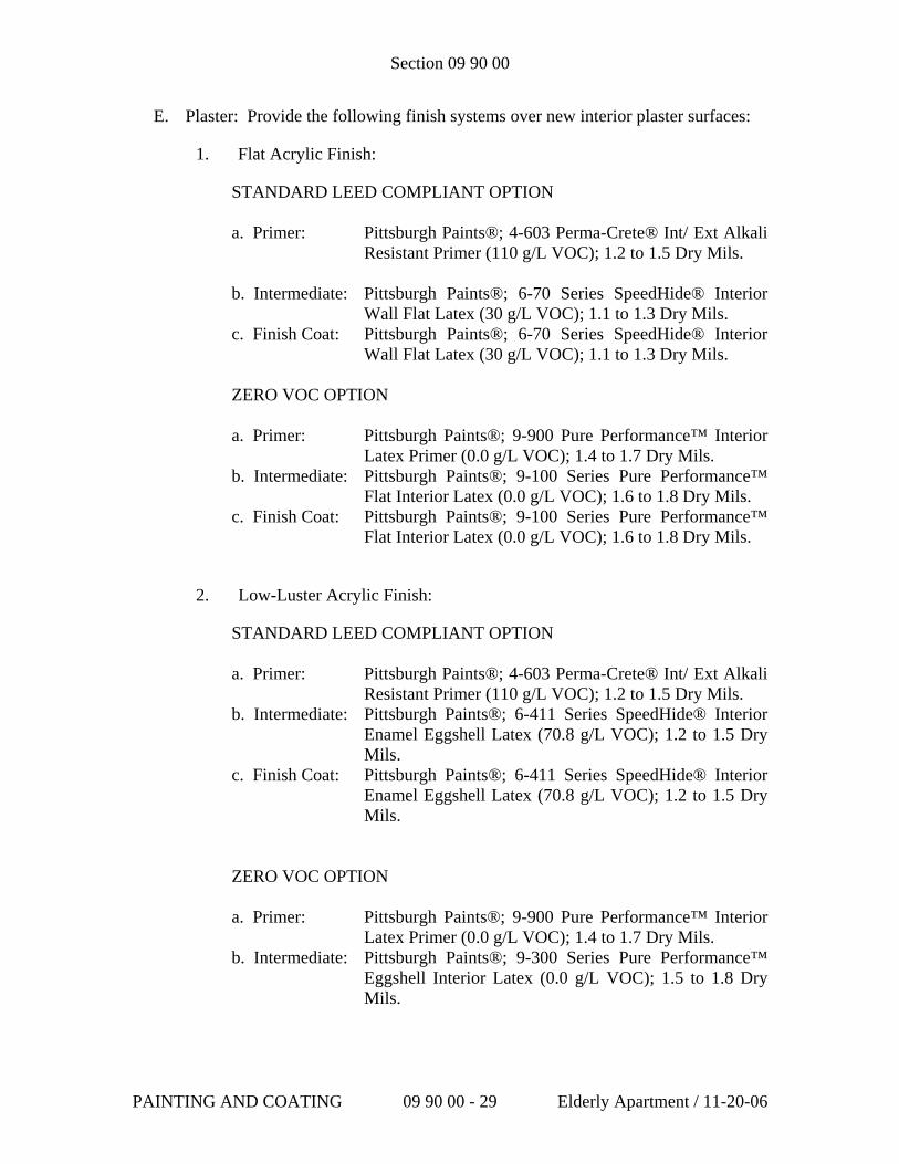
Section 09 90 00
E. Plaster: Provide the following finish systems over new interior plaster surfaces:
1. Flat Acrylic Finish:
STANDARD LEED COMPLIANT OPTION a. Primer: Pittsburgh Paints®; 4-603 Perma-Crete® Int/ Ext Alkali
Resistant Primer (110 g/L VOC); 1.2 to 1.5 Dry Mils. b. Intermediate: Pittsburgh Paints®; 6-70 Series SpeedHide® Interior
Wall Flat Latex (30 g/L VOC); 1.1 to 1.3 Dry Mils. c. Finish Coat: Pittsburgh Paints®; 6-70 Series SpeedHide® Interior
Wall Flat Latex (30 g/L VOC); 1.1 to 1.3 Dry Mils. ZERO VOC OPTION a. Primer: Pittsburgh Paints®; 9-900 Pure Performance™ Interior
Latex Primer (0.0 g/L VOC); 1.4 to 1.7 Dry Mils. b. Intermediate: Pittsburgh Paints®; 9-100 Series Pure Performance™
Flat Interior Latex (0.0 g/L VOC); 1.6 to 1.8 Dry Mils. c. Finish Coat: Pittsburgh Paints®; 9-100 Series Pure Performance™
Flat Interior Latex (0.0 g/L VOC); 1.6 to 1.8 Dry Mils.
2. Low-Luster Acrylic Finish:
STANDARD LEED COMPLIANT OPTION
a. Primer: Pittsburgh Paints®; 4-603 Perma-Crete® Int/ Ext Alkali Resistant Primer (110 g/L VOC); 1.2 to 1.5 Dry Mils.
b. Intermediate: Pittsburgh Paints®; 6-411 Series SpeedHide® Interior Enamel Eggshell Latex (70.8 g/L VOC); 1.2 to 1.5 Dry Mils.
c. Finish Coat: Pittsburgh Paints®; 6-411 Series SpeedHide® Interior Enamel Eggshell Latex (70.8 g/L VOC); 1.2 to 1.5 Dry Mils.
ZERO VOC OPTION a. Primer: Pittsburgh Paints®; 9-900 Pure Performance™ Interior
Latex Primer (0.0 g/L VOC); 1.4 to 1.7 Dry Mils. b. Intermediate: Pittsburgh Paints®; 9-300 Series Pure Performance™
Eggshell Interior Latex (0.0 g/L VOC); 1.5 to 1.8 Dry Mils.
PAINTING AND COATING 09 90 00 - 29 Elderly Apartment / 11-20-06
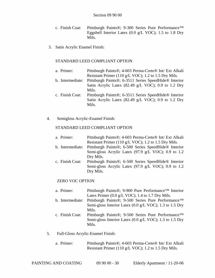
Section 09 90 00
c. Finish Coat: Pittsburgh Paints®; 9-300 Series Pure Performance™ Eggshell Interior Latex (0.0 g/L VOC); 1.5 to 1.8 Dry Mils.
3. Satin Acrylic Enamel Finish:
STANDARD LEED COMPLIANT OPTION
a. Primer: Pittsburgh Paints®; 4-603 Perma-Crete® Int/ Ext Alkali Resistant Primer (110 g/L VOC); 1.2 to 1.5 Dry Mils.
b. Intermediate: Pittsburgh Paints®; 6-3511 Series SpeedHide® Interior Satin Acrylic Latex (82.49 g/L VOC); 0.9 to 1.2 Dry Mils.
c. Finish Coat: Pittsburgh Paints®; 6-3511 Series SpeedHide® Interior Satin Acrylic Latex (82.49 g/L VOC); 0.9 to 1.2 Dry Mils.
4. Semigloss Acrylic-Enamel Finish:
STANDARD LEED COMPLIANT OPTION
a. Primer: Pittsburgh Paints®; 4-603 Perma-Crete® Int/ Ext Alkali Resistant Primer (110 g/L VOC); 1.2 to 1.5 Dry Mils.
b. Intermediate: Pittsburgh Paints®; 6-500 Series SpeedHide® Interior Semi-gloss Acrylic Latex (97.9 g/L VOC); 0.9 to 1.2 Dry Mils.
c. Finish Coat: Pittsburgh Paints®; 6-500 Series SpeedHide® Interior Semi-gloss Acrylic Latex (97.9 g/L VOC); 0.9 to 1.2 Dry Mils.
ZERO VOC OPTION
a. Primer: Pittsburgh Paints®; 9-900 Pure Performance™ Interior
Latex Primer (0.0 g/L VOC); 1.4 to 1.7 Dry Mils. b. Intermediate: Pittsburgh Paints®; 9-500 Series Pure Performance™
Semi-gloss Interior Latex (0.0 g/L VOC); 1.3 to 1.5 Dry Mils.
c. Finish Coat: Pittsburgh Paints®; 9-500 Series Pure Performance™ Semi-gloss Interior Latex (0.0 g/L VOC); 1.3 to 1.5 Dry Mils.
5. Full-Gloss Acrylic-Enamel Finish:
a. Primer: Pittsburgh Paints®; 4-603 Perma-Crete® Int/ Ext Alkali Resistant Primer (110 g/L VOC); 1.2 to 1.5 Dry Mils.
PAINTING AND COATING 09 90 00 - 30 Elderly Apartment / 11-20-06
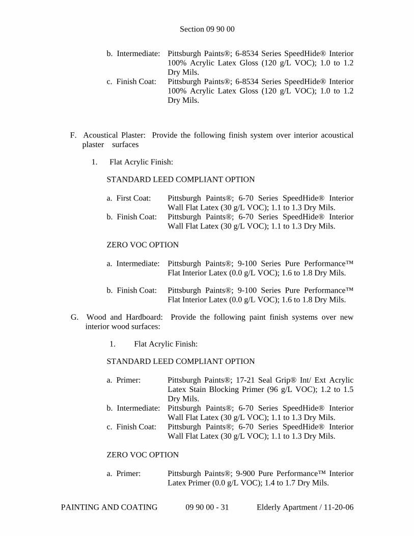
Section 09 90 00
b. Intermediate: Pittsburgh Paints®; 6-8534 Series SpeedHide® Interior 100% Acrylic Latex Gloss (120 g/L VOC); 1.0 to 1.2 Dry Mils.
c. Finish Coat: Pittsburgh Paints®; 6-8534 Series SpeedHide® Interior 100% Acrylic Latex Gloss (120 g/L VOC); 1.0 to 1.2 Dry Mils.
F. Acoustical Plaster: Provide the following finish system over interior acoustical plaster surfaces
1. Flat Acrylic Finish:
STANDARD LEED COMPLIANT OPTION a. First Coat: Pittsburgh Paints®; 6-70 Series SpeedHide® Interior
Wall Flat Latex (30 g/L VOC); 1.1 to 1.3 Dry Mils. b. Finish Coat: Pittsburgh Paints®; 6-70 Series SpeedHide® Interior
Wall Flat Latex (30 g/L VOC); 1.1 to 1.3 Dry Mils. ZERO VOC OPTION a. Intermediate: Pittsburgh Paints®; 9-100 Series Pure Performance™
Flat Interior Latex (0.0 g/L VOC); 1.6 to 1.8 Dry Mils.
b. Finish Coat: Pittsburgh Paints®; 9-100 Series Pure Performance™ Flat Interior Latex (0.0 g/L VOC); 1.6 to 1.8 Dry Mils.
G. Wood and Hardboard: Provide the following paint finish systems over new interior wood surfaces:
1. Flat Acrylic Finish:
STANDARD LEED COMPLIANT OPTION a. Primer: Pittsburgh Paints®; 17-21 Seal Grip® Int/ Ext Acrylic
Latex Stain Blocking Primer (96 g/L VOC); 1.2 to 1.5 Dry Mils.
b. Intermediate: Pittsburgh Paints®; 6-70 Series SpeedHide® Interior Wall Flat Latex (30 g/L VOC); 1.1 to 1.3 Dry Mils.
c. Finish Coat: Pittsburgh Paints®; 6-70 Series SpeedHide® Interior Wall Flat Latex (30 g/L VOC); 1.1 to 1.3 Dry Mils.
ZERO VOC OPTION a. Primer: Pittsburgh Paints®; 9-900 Pure Performance™ Interior
Latex Primer (0.0 g/L VOC); 1.4 to 1.7 Dry Mils.
PAINTING AND COATING 09 90 00 - 31 Elderly Apartment / 11-20-06
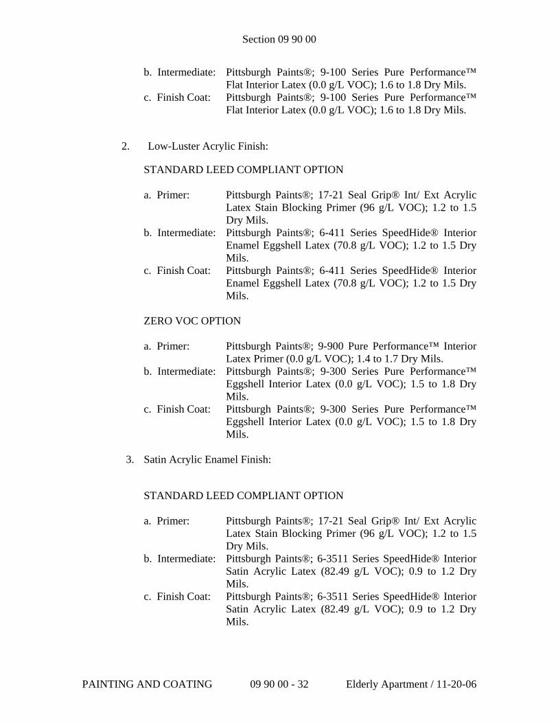
Section 09 90 00
b. Intermediate: Pittsburgh Paints®; 9-100 Series Pure Performance™ Flat Interior Latex (0.0 g/L VOC); 1.6 to 1.8 Dry Mils.
c. Finish Coat: Pittsburgh Paints®; 9-100 Series Pure Performance™ Flat Interior Latex (0.0 g/L VOC); 1.6 to 1.8 Dry Mils.
2. Low-Luster Acrylic Finish:
STANDARD LEED COMPLIANT OPTION
a. Primer: Pittsburgh Paints®; 17-21 Seal Grip® Int/ Ext Acrylic Latex Stain Blocking Primer (96 g/L VOC); 1.2 to 1.5 Dry Mils.
b. Intermediate: Pittsburgh Paints®; 6-411 Series SpeedHide® Interior Enamel Eggshell Latex (70.8 g/L VOC); 1.2 to 1.5 Dry Mils.
c. Finish Coat: Pittsburgh Paints®; 6-411 Series SpeedHide® Interior Enamel Eggshell Latex (70.8 g/L VOC); 1.2 to 1.5 Dry Mils.
ZERO VOC OPTION a. Primer: Pittsburgh Paints®; 9-900 Pure Performance™ Interior
Latex Primer (0.0 g/L VOC); 1.4 to 1.7 Dry Mils. b. Intermediate: Pittsburgh Paints®; 9-300 Series Pure Performance™
Eggshell Interior Latex (0.0 g/L VOC); 1.5 to 1.8 Dry Mils.
c. Finish Coat: Pittsburgh Paints®; 9-300 Series Pure Performance™ Eggshell Interior Latex (0.0 g/L VOC); 1.5 to 1.8 Dry Mils.
3. Satin Acrylic Enamel Finish:
STANDARD LEED COMPLIANT OPTION
a. Primer: Pittsburgh Paints®; 17-21 Seal Grip® Int/ Ext Acrylic Latex Stain Blocking Primer (96 g/L VOC); 1.2 to 1.5 Dry Mils.
b. Intermediate: Pittsburgh Paints®; 6-3511 Series SpeedHide® Interior Satin Acrylic Latex (82.49 g/L VOC); 0.9 to 1.2 Dry Mils.
c. Finish Coat: Pittsburgh Paints®; 6-3511 Series SpeedHide® Interior Satin Acrylic Latex (82.49 g/L VOC); 0.9 to 1.2 Dry Mils.
PAINTING AND COATING 09 90 00 - 32 Elderly Apartment / 11-20-06
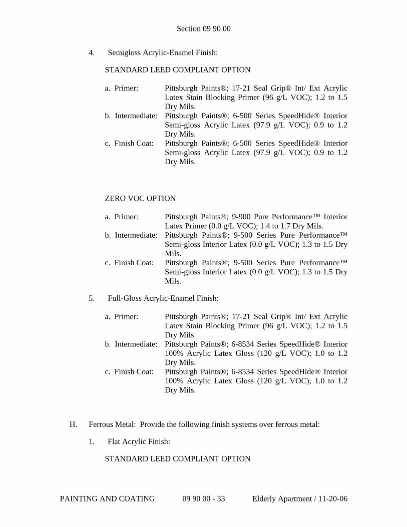
Section 09 90 00
4. Semigloss Acrylic-Enamel Finish:
STANDARD LEED COMPLIANT OPTION
a. Primer: Pittsburgh Paints®; 17-21 Seal Grip® Int/ Ext Acrylic Latex Stain Blocking Primer (96 g/L VOC); 1.2 to 1.5 Dry Mils.
b. Intermediate: Pittsburgh Paints®; 6-500 Series SpeedHide® Interior Semi-gloss Acrylic Latex (97.9 g/L VOC); 0.9 to 1.2 Dry Mils.
c. Finish Coat: Pittsburgh Paints®; 6-500 Series SpeedHide® Interior Semi-gloss Acrylic Latex (97.9 g/L VOC); 0.9 to 1.2 Dry Mils.
ZERO VOC OPTION
a. Primer: Pittsburgh Paints®; 9-900 Pure Performance™ Interior Latex Primer (0.0 g/L VOC); 1.4 to 1.7 Dry Mils.
b. Intermediate: Pittsburgh Paints®; 9-500 Series Pure Performance™ Semi-gloss Interior Latex (0.0 g/L VOC); 1.3 to 1.5 Dry Mils.
c. Finish Coat: Pittsburgh Paints®; 9-500 Series Pure Performance™ Semi-gloss Interior Latex (0.0 g/L VOC); 1.3 to 1.5 Dry Mils.
5. Full-Gloss Acrylic-Enamel Finish:
a. Primer: Pittsburgh Paints®; 17-21 Seal Grip® Int/ Ext Acrylic Latex Stain Blocking Primer (96 g/L VOC); 1.2 to 1.5 Dry Mils.
b. Intermediate: Pittsburgh Paints®; 6-8534 Series SpeedHide® Interior 100% Acrylic Latex Gloss (120 g/L VOC); 1.0 to 1.2 Dry Mils.
c. Finish Coat: Pittsburgh Paints®; 6-8534 Series SpeedHide® Interior 100% Acrylic Latex Gloss (120 g/L VOC); 1.0 to 1.2 Dry Mils.
H. Ferrous Metal: Provide the following finish systems over ferrous metal:
1. Flat Acrylic Finish:
STANDARD LEED COMPLIANT OPTION
PAINTING AND COATING 09 90 00 - 33 Elderly Apartment / 11-20-06
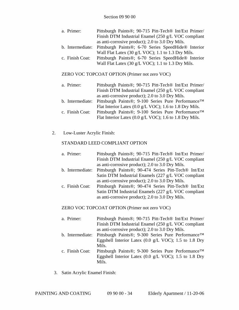
Section 09 90 00
a. Primer: Pittsburgh Paints®; 90-715 Pitt-Tech® Int/Ext Primer/ Finish DTM Industrial Enamel (250 g/L VOC compliant as anti-corrosive product); 2.0 to 3.0 Dry Mils.
b. Intermediate: Pittsburgh Paints®; 6-70 Series SpeedHide® Interior Wall Flat Latex (30 g/L VOC); 1.1 to 1.3 Dry Mils.
c. Finish Coat: Pittsburgh Paints®; 6-70 Series SpeedHide® Interior Wall Flat Latex (30 g/L VOC); 1.1 to 1.3 Dry Mils.
ZERO VOC TOPCOAT OPTION (Primer not zero VOC) a. Primer: Pittsburgh Paints®; 90-715 Pitt-Tech® Int/Ext Primer/
Finish DTM Industrial Enamel (250 g/L VOC compliant as anti-corrosive product); 2.0 to 3.0 Dry Mils.
b. Intermediate: Pittsburgh Paints®; 9-100 Series Pure Performance™ Flat Interior Latex (0.0 g/L VOC); 1.6 to 1.8 Dry Mils.
c. Finish Coat: Pittsburgh Paints®; 9-100 Series Pure Performance™ Flat Interior Latex (0.0 g/L VOC); 1.6 to 1.8 Dry Mils.
2. Low-Luster Acrylic Finish:
STANDARD LEED COMPLIANT OPTION
a. Primer: Pittsburgh Paints®; 90-715 Pitt-Tech® Int/Ext Primer/ Finish DTM Industrial Enamel (250 g/L VOC compliant as anti-corrosive product); 2.0 to 3.0 Dry Mils.
b. Intermediate: Pittsburgh Paints®; 90-474 Series Pitt-Tech® Int/Ext Satin DTM Industrial Enamels (227 g/L VOC compliant as anti-corrosive product); 2.0 to 3.0 Dry Mils.
c. Finish Coat: Pittsburgh Paints®; 90-474 Series Pitt-Tech® Int/Ext Satin DTM Industrial Enamels (227 g/L VOC compliant as anti-corrosive product); 2.0 to 3.0 Dry Mils.
ZERO VOC TOPCOAT OPTION (Primer not zero VOC) a. Primer: Pittsburgh Paints®; 90-715 Pitt-Tech® Int/Ext Primer/
Finish DTM Industrial Enamel (250 g/L VOC compliant as anti-corrosive product); 2.0 to 3.0 Dry Mils.
b. Intermediate: Pittsburgh Paints®; 9-300 Series Pure Performance™ Eggshell Interior Latex (0.0 g/L VOC); 1.5 to 1.8 Dry Mils.
c. Finish Coat: Pittsburgh Paints®; 9-300 Series Pure Performance™ Eggshell Interior Latex (0.0 g/L VOC); 1.5 to 1.8 Dry Mils.
3. Satin Acrylic Enamel Finish:
PAINTING AND COATING 09 90 00 - 34 Elderly Apartment / 11-20-06
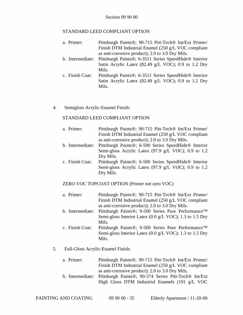
Section 09 90 00
STANDARD LEED COMPLIANT OPTION
a. Primer: Pittsburgh Paints®; 90-715 Pitt-Tech® Int/Ext Primer/ Finish DTM Industrial Enamel (250 g/L VOC compliant as anti-corrosive product); 2.0 to 3.0 Dry Mils.
b. Intermediate: Pittsburgh Paints®; 6-3511 Series SpeedHide® Interior Satin Acrylic Latex (82.49 g/L VOC); 0.9 to 1.2 Dry Mils.
c. Finish Coat: Pittsburgh Paints®; 6-3511 Series SpeedHide® Interior Satin Acrylic Latex (82.49 g/L VOC); 0.9 to 1.2 Dry Mils.
4. Semigloss Acrylic-Enamel Finish:
STANDARD LEED COMPLIANT OPTION
a. Primer: Pittsburgh Paints®; 90-715 Pitt-Tech® Int/Ext Primer/ Finish DTM Industrial Enamel (250 g/L VOC compliant as anti-corrosive product); 2.0 to 3.0 Dry Mils.
b. Intermediate: Pittsburgh Paints®; 6-500 Series SpeedHide® Interior Semi-gloss Acrylic Latex (97.9 g/L VOC); 0.9 to 1.2 Dry Mils.
c. Finish Coat: Pittsburgh Paints®; 6-500 Series SpeedHide® Interior Semi-gloss Acrylic Latex (97.9 g/L VOC); 0.9 to 1.2 Dry Mils.
ZERO VOC TOPCOAT OPTION (Primer not zero VOC)
a. Primer: Pittsburgh Paints®; 90-715 Pitt-Tech® Int/Ext Primer/ Finish DTM Industrial Enamel (250 g/L VOC compliant as anti-corrosive product); 2.0 to 3.0 Dry Mils.
b. Intermediate: Pittsburgh Paints®; 9-500 Series Pure Performance™ Semi-gloss Interior Latex (0.0 g/L VOC); 1.3 to 1.5 Dry Mils.
c. Finish Coat: Pittsburgh Paints®; 9-500 Series Pure Performance™ Semi-gloss Interior Latex (0.0 g/L VOC); 1.3 to 1.5 Dry Mils.
5. Full-Gloss Acrylic-Enamel Finish:
a. Primer: Pittsburgh Paints®; 90-715 Pitt-Tech® Int/Ext Primer/ Finish DTM Industrial Enamel (250 g/L VOC compliant as anti-corrosive product); 2.0 to 3.0 Dry Mils.
b. Intermediate: Pittsburgh Paints®; 90-374 Series Pitt-Tech® Int/Ext High Gloss DTM Industrial Enamels (191 g/L VOC
PAINTING AND COATING 09 90 00 - 35 Elderly Apartment / 11-20-06
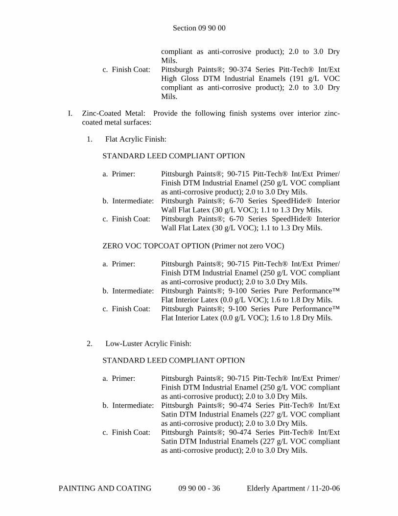
Section 09 90 00
compliant as anti-corrosive product); 2.0 to 3.0 Dry Mils.
c. Finish Coat: Pittsburgh Paints®; 90-374 Series Pitt-Tech® Int/Ext High Gloss DTM Industrial Enamels (191 g/L VOC compliant as anti-corrosive product); 2.0 to 3.0 Dry Mils.
I. Zinc-Coated Metal: Provide the following finish systems over interior zinc-coated metal surfaces:
1. Flat Acrylic Finish:
STANDARD LEED COMPLIANT OPTION a. Primer: Pittsburgh Paints®; 90-715 Pitt-Tech® Int/Ext Primer/
Finish DTM Industrial Enamel (250 g/L VOC compliant as anti-corrosive product); 2.0 to 3.0 Dry Mils.
b. Intermediate: Pittsburgh Paints®; 6-70 Series SpeedHide® Interior Wall Flat Latex (30 g/L VOC); 1.1 to 1.3 Dry Mils.
c. Finish Coat: Pittsburgh Paints®; 6-70 Series SpeedHide® Interior Wall Flat Latex (30 g/L VOC); 1.1 to 1.3 Dry Mils.
ZERO VOC TOPCOAT OPTION (Primer not zero VOC) a. Primer: Pittsburgh Paints®; 90-715 Pitt-Tech® Int/Ext Primer/
Finish DTM Industrial Enamel (250 g/L VOC compliant as anti-corrosive product); 2.0 to 3.0 Dry Mils.
b. Intermediate: Pittsburgh Paints®; 9-100 Series Pure Performance™ Flat Interior Latex (0.0 g/L VOC); 1.6 to 1.8 Dry Mils.
c. Finish Coat: Pittsburgh Paints®; 9-100 Series Pure Performance™ Flat Interior Latex (0.0 g/L VOC); 1.6 to 1.8 Dry Mils.
2. Low-Luster Acrylic Finish:
STANDARD LEED COMPLIANT OPTION
a. Primer: Pittsburgh Paints®; 90-715 Pitt-Tech® Int/Ext Primer/ Finish DTM Industrial Enamel (250 g/L VOC compliant as anti-corrosive product); 2.0 to 3.0 Dry Mils.
b. Intermediate: Pittsburgh Paints®; 90-474 Series Pitt-Tech® Int/Ext Satin DTM Industrial Enamels (227 g/L VOC compliant as anti-corrosive product); 2.0 to 3.0 Dry Mils.
c. Finish Coat: Pittsburgh Paints®; 90-474 Series Pitt-Tech® Int/Ext Satin DTM Industrial Enamels (227 g/L VOC compliant as anti-corrosive product); 2.0 to 3.0 Dry Mils.
PAINTING AND COATING 09 90 00 - 36 Elderly Apartment / 11-20-06
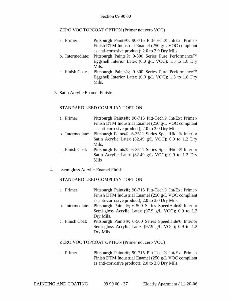
Section 09 90 00
ZERO VOC TOPCOAT OPTION (Primer not zero VOC) a. Primer: Pittsburgh Paints®; 90-715 Pitt-Tech® Int/Ext Primer/
Finish DTM Industrial Enamel (250 g/L VOC compliant as anti-corrosive product); 2.0 to 3.0 Dry Mils.
b. Intermediate: Pittsburgh Paints®; 9-300 Series Pure Performance™ Eggshell Interior Latex (0.0 g/L VOC); 1.5 to 1.8 Dry Mils.
c. Finish Coat: Pittsburgh Paints®; 9-300 Series Pure Performance™ Eggshell Interior Latex (0.0 g/L VOC); 1.5 to 1.8 Dry Mils.
3. Satin Acrylic Enamel Finish:
STANDARD LEED COMPLIANT OPTION
a. Primer: Pittsburgh Paints®; 90-715 Pitt-Tech® Int/Ext Primer/ Finish DTM Industrial Enamel (250 g/L VOC compliant as anti-corrosive product); 2.0 to 3.0 Dry Mils.
b. Intermediate: Pittsburgh Paints®; 6-3511 Series SpeedHide® Interior Satin Acrylic Latex (82.49 g/L VOC); 0.9 to 1.2 Dry Mils.
c. Finish Coat: Pittsburgh Paints®; 6-3511 Series SpeedHide® Interior Satin Acrylic Latex (82.49 g/L VOC); 0.9 to 1.2 Dry Mils
4. Semigloss Acrylic-Enamel Finish:
STANDARD LEED COMPLIANT OPTION
a. Primer: Pittsburgh Paints®; 90-715 Pitt-Tech® Int/Ext Primer/ Finish DTM Industrial Enamel (250 g/L VOC compliant as anti-corrosive product); 2.0 to 3.0 Dry Mils.
b. Intermediate: Pittsburgh Paints®; 6-500 Series SpeedHide® Interior Semi-gloss Acrylic Latex (97.9 g/L VOC); 0.9 to 1.2 Dry Mils.
c. Finish Coat: Pittsburgh Paints®; 6-500 Series SpeedHide® Interior Semi-gloss Acrylic Latex (97.9 g/L VOC); 0.9 to 1.2 Dry Mils.
ZERO VOC TOPCOAT OPTION (Primer not zero VOC)
a. Primer: Pittsburgh Paints®; 90-715 Pitt-Tech® Int/Ext Primer/ Finish DTM Industrial Enamel (250 g/L VOC compliant as anti-corrosive product); 2.0 to 3.0 Dry Mils.
PAINTING AND COATING 09 90 00 - 37 Elderly Apartment / 11-20-06
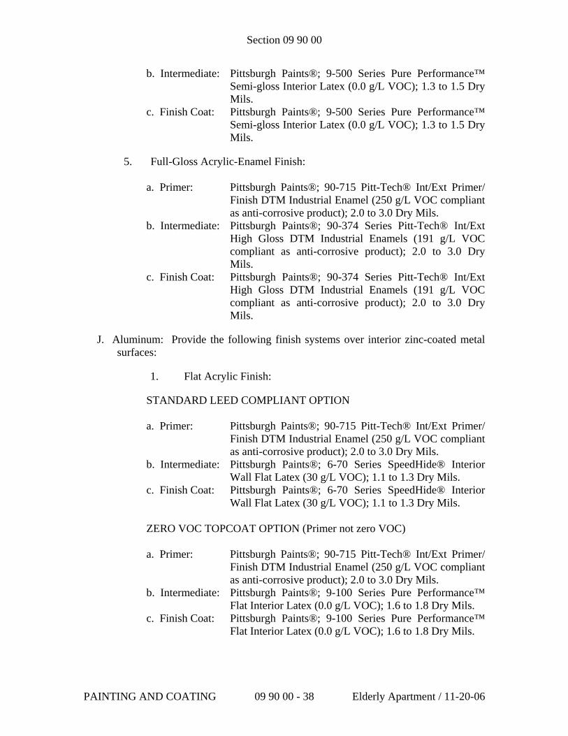
Section 09 90 00
b. Intermediate: Pittsburgh Paints®; 9-500 Series Pure Performance™ Semi-gloss Interior Latex (0.0 g/L VOC); 1.3 to 1.5 Dry Mils.
c. Finish Coat: Pittsburgh Paints®; 9-500 Series Pure Performance™ Semi-gloss Interior Latex (0.0 g/L VOC); 1.3 to 1.5 Dry Mils.
5. Full-Gloss Acrylic-Enamel Finish:
a. Primer: Pittsburgh Paints®; 90-715 Pitt-Tech® Int/Ext Primer/ Finish DTM Industrial Enamel (250 g/L VOC compliant as anti-corrosive product); 2.0 to 3.0 Dry Mils.
b. Intermediate: Pittsburgh Paints®; 90-374 Series Pitt-Tech® Int/Ext High Gloss DTM Industrial Enamels (191 g/L VOC compliant as anti-corrosive product); 2.0 to 3.0 Dry Mils.
c. Finish Coat: Pittsburgh Paints®; 90-374 Series Pitt-Tech® Int/Ext High Gloss DTM Industrial Enamels (191 g/L VOC compliant as anti-corrosive product); 2.0 to 3.0 Dry Mils.
J. Aluminum: Provide the following finish systems over interior zinc-coated metal surfaces:
1. Flat Acrylic Finish:
STANDARD LEED COMPLIANT OPTION a. Primer: Pittsburgh Paints®; 90-715 Pitt-Tech® Int/Ext Primer/
Finish DTM Industrial Enamel (250 g/L VOC compliant as anti-corrosive product); 2.0 to 3.0 Dry Mils.
b. Intermediate: Pittsburgh Paints®; 6-70 Series SpeedHide® Interior Wall Flat Latex (30 g/L VOC); 1.1 to 1.3 Dry Mils.
c. Finish Coat: Pittsburgh Paints®; 6-70 Series SpeedHide® Interior Wall Flat Latex (30 g/L VOC); 1.1 to 1.3 Dry Mils.
ZERO VOC TOPCOAT OPTION (Primer not zero VOC) a. Primer: Pittsburgh Paints®; 90-715 Pitt-Tech® Int/Ext Primer/
Finish DTM Industrial Enamel (250 g/L VOC compliant as anti-corrosive product); 2.0 to 3.0 Dry Mils.
b. Intermediate: Pittsburgh Paints®; 9-100 Series Pure Performance™ Flat Interior Latex (0.0 g/L VOC); 1.6 to 1.8 Dry Mils.
c. Finish Coat: Pittsburgh Paints®; 9-100 Series Pure Performance™ Flat Interior Latex (0.0 g/L VOC); 1.6 to 1.8 Dry Mils.
PAINTING AND COATING 09 90 00 - 38 Elderly Apartment / 11-20-06
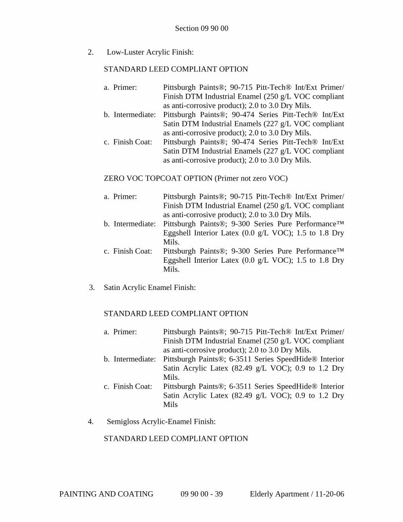
Section 09 90 00
2. Low-Luster Acrylic Finish:
STANDARD LEED COMPLIANT OPTION
a. Primer: Pittsburgh Paints®; 90-715 Pitt-Tech® Int/Ext Primer/ Finish DTM Industrial Enamel (250 g/L VOC compliant as anti-corrosive product); 2.0 to 3.0 Dry Mils.
b. Intermediate: Pittsburgh Paints®; 90-474 Series Pitt-Tech® Int/Ext Satin DTM Industrial Enamels (227 g/L VOC compliant as anti-corrosive product); 2.0 to 3.0 Dry Mils.
c. Finish Coat: Pittsburgh Paints®; 90-474 Series Pitt-Tech® Int/Ext Satin DTM Industrial Enamels (227 g/L VOC compliant as anti-corrosive product); 2.0 to 3.0 Dry Mils.
ZERO VOC TOPCOAT OPTION (Primer not zero VOC) a. Primer: Pittsburgh Paints®; 90-715 Pitt-Tech® Int/Ext Primer/
Finish DTM Industrial Enamel (250 g/L VOC compliant as anti-corrosive product); 2.0 to 3.0 Dry Mils.
b. Intermediate: Pittsburgh Paints®; 9-300 Series Pure Performance™ Eggshell Interior Latex (0.0 g/L VOC); 1.5 to 1.8 Dry Mils.
c. Finish Coat: Pittsburgh Paints®; 9-300 Series Pure Performance™ Eggshell Interior Latex (0.0 g/L VOC); 1.5 to 1.8 Dry Mils.
3. Satin Acrylic Enamel Finish:
STANDARD LEED COMPLIANT OPTION
a. Primer: Pittsburgh Paints®; 90-715 Pitt-Tech® Int/Ext Primer/ Finish DTM Industrial Enamel (250 g/L VOC compliant as anti-corrosive product); 2.0 to 3.0 Dry Mils.
b. Intermediate: Pittsburgh Paints®; 6-3511 Series SpeedHide® Interior Satin Acrylic Latex (82.49 g/L VOC); 0.9 to 1.2 Dry Mils.
c. Finish Coat: Pittsburgh Paints®; 6-3511 Series SpeedHide® Interior Satin Acrylic Latex (82.49 g/L VOC); 0.9 to 1.2 Dry Mils
4. Semigloss Acrylic-Enamel Finish:
STANDARD LEED COMPLIANT OPTION
PAINTING AND COATING 09 90 00 - 39 Elderly Apartment / 11-20-06
Section 09 90 00
a. Primer: Pittsburgh Paints®; 90-715 Pitt-Tech® Int/Ext Primer/ Finish DTM Industrial Enamel (250 g/L VOC compliant as anti-corrosive product); 2.0 to 3.0 Dry Mils.
b. Intermediate: Pittsburgh Paints®; 6-500 Series SpeedHide® Interior Semi-gloss Acrylic Latex (97.9 g/L VOC); 0.9 to 1.2 Dry Mils.
c. Finish Coat: Pittsburgh Paints®; 6-500 Series SpeedHide® Interior Semi-gloss Acrylic Latex (97.9g/L VOC); 0.9 to 1.2 Dry Mils.
ZERO VOC TOPCOAT OPTION (Primer not zero VOC)
a. Primer: Pittsburgh Paints®; 90-715 Pitt-Tech® Int/Ext Primer/ Finish DTM Industrial Enamel (250 g/L VOC compliant as anti-corrosive product); 2.0 to 3.0 Dry Mils.
b. Intermediate: Pittsburgh Paints®; 9-500 Series Pure Performance™ Semi-gloss Interior Latex (0.0 g/L VOC); 1.3 to 1.5 Dry Mils.
c. Finish Coat: Pittsburgh Paints®; 9-500 Series Pure Performance™ Semi-gloss Interior Latex (0.0 g/L VOC); 1.3 to 1.5 Dry Mils.
5. Full-Gloss Acrylic-Enamel Finish:
a. Primer: Pittsburgh Paints®; 90-715 Pitt-Tech® Int/Ext Primer/ Finish DTM Industrial Enamel (250 g/L VOC compliant as anti-corrosive product); 2.0 to 3.0 Dry Mils.
b. Intermediate: Pittsburgh Paints®; 90-374 Series Pitt-Tech® Int/Ext High Gloss DTM Industrial Enamels (191 g/L VOC compliant as anti-corrosive product); 2.0 to 3.0 Dry Mils.
c. Finish Coat: Pittsburgh Paints®; 90-374 Series Pitt-Tech® Int/Ext High Gloss DTM Industrial Enamels (191 g/L VOC compliant as anti-corrosive product); 2.0 to 3.0 Dry Mils.
J. All-Service Jacket over Insulation: Provide the following finish system on cotton or canvas insulation covering:
1. Flat Acrylic Finish:
STANDARD LEED COMPLIANT OPTION a. First Coat: Pittsburgh Paints®; 6-70 Series SpeedHide® Interior
Wall Flat Latex (30 g/L VOC); 1.1 to 1.3 Dry Mils.
PAINTING AND COATING 09 90 00 - 40 Elderly Apartment / 11-20-06
Section 09 90 00
b. Finish Coat: Pittsburgh Paints®; 6-70 Series SpeedHide® Interior Wall Flat Latex (30 g/L VOC); 1.1 to 1.3 Dry Mils.
ZERO VOC OPTION a. Intermediate: Pittsburgh Paints®; 9-100 Series Pure Performance™
Flat Interior Latex (0.0 g/L VOC); 1.6 to 1.8 Dry Mils.
b. Finish Coat: Pittsburgh Paints®; 9-100 Series Pure Performance™ Flat Interior Latex (0.0 g/L VOC); 1.6 to 1.8 Dry Mils.
END OF SECTION 09900
PAINTING AND COATING 09 90 00 - 41 Elderly Apartment / 11-20-06
SECTION 09 93 00
STAINS AND TRANSPARENT FINISHES PART 1 GENERAL 1.1 SECTION INCLUDES
A. Filling and patching wood surfaces.
B. Penetrating wood floor finish.
C. Pastel wood floor stain.
D. Fast drying wood floor stain. 1. Wood floors. 2. Unglazed tile floors.
E. Fast drying floor sealer.
1. Wood floors. 2. Unglazed terra cotta tile.
F. Polyurethane wood floor finish.
1. New wood floors. 2. Recoating. 3. Old wood floors.
G. Waterborne wood floor finish.
1. Single component type. 2. Two component, non-ambering type.
H. Putty for finished wood floors.
I. Floor cleaner and reconditioner.
1. Hardwood floors. 2. Terrazzo. 3. Concrete. 4. Unglazed terra cotta tile.
J. Paste wax floor finish.
1. New wood floors. 2. Old wood floors.
K. Liquid wax finish.
Elderly Apartment / 4-28-06 09 93 00-1 Stains and Transparent Finishes
1. Wood floors. 2. Unglazed tile.
L. Floor wax and cleaner.
M. Hardwood floor cleaner.
N. Gym floor sealer and finish.
O. Gym floor penetrating finish.
1.2 RELATED SECTIONS
A. Section 03300 - Cast-In-Place Concrete.
B. Section 09300 - Tile.
C. Section 09340 - Paver Tile.
D. Section 09400 - Terrazzo.
E. Section 09640 - Wood Flooring.
F. Section 09690 - Flooring Restoration. 1.3 REFERENCES
A. NOFMA - National Oak Flooring Manufacturers Association.
B. NWFA - National Wood Flooring Association. 1.4 SUBMITTALS
A. Submit under provisions of Section 01300.
B. Three copies of manufacturer's current technical data sheets for materials.
C. Samples: 1. Opaque: One draw down of each specified color. 2. Semi-Transparent: Substrate with two transparent variations.
1.5 QUALITY ASSURANCE
A. Installer Qualifications: Minimum five years experience regularly engaged and specializing in the application of stains and transparent finishes to floors.
Elderly Apartment / 4-28-06 09 93 00-2 Stains and Transparent Finishes
B. Pre-Installation Meetings: 1. Before Application: Installer shall inspect surfaces to be treated, noting
in writing to the Architect, deficiencies or flaws which would affect the performance or appearance of the finish.
2. Beginning of Application: Manufacturer's Representative shall assure utilization of proper equipment, verify material quantities, and supervise material application techniques upon a substantial floor section. This section shall act as a comparative standard for the project.
C. Installer shall not proceed with material application until all deficiencies
noted in pre-application inspection report have been corrected.
D. Installer shall notify manufacturer no less than 5 days before starting application.
1.6 DELIVERY, STORAGE AND HANDLING
A. Deliver materials in original sealed containers, clearly marked with manufacturer's name, type of material, and batch number.
B. Inspect the materials upon delivery to assure that specified products have
been received.
C. Store materials where temperatures are not less than 40 degrees F (4.5 degrees C).
D. Use all means necessary to protect material before, during, and after
installation, and to protect work of other trades. 1.7 ENVIRONMENTAL REQUIREMENTS
A. Comply with current Federal and State environmental requirements. PART 2 PRODUCTS 2.1 MANUFACTURERS
A. Acceptable Manufacturer: Dura Seal, 224 Catherine Street, Ft. Erie, Ontario L2A 5M9. ASD. Te1: (905) 871-2724, Tel: (800) 364-1359, Fax: (905) 871-5455
B. Requests for substitutions will be considered in accordance with provisions
of Section 01600.
C. Substitutions: Not permitted.
Elderly Apartment / 4-28-06 09 93 00-3 Stains and Transparent Finishes
D. Provide all stains and transparent finishes from a single manufacturer. 2.2 MATERIALS
A. Filler and Patching Compound: Dura Seal(R) "Filler and Patch" products, designed to fill open grain and patch nail holes in bare and unfinished wood. 1. Color: White Oak. 2. Color: Red Oak. 3. Color: Maple/Ash/Pine.
B. Penetrating Wood Floor Finish: Dura Seal(R) "Penetrating Wood Finish"
semitransparent stain; oil and resin blend. 1. Color: No. 200 Natural. 2. Color: No. 202 Nutmeg. 3. Color: No. 204 Chestnut. 4. Color: No. 208 Royal Mahogany. 5. Color: No. 210 Neutral. 6. Color: No. 216 Antique Brown. 7. Color: No. 221 Golden Brown. 8. Color: No. 223 Coffee Brown. 9. Color: No. 228 Medium Brown. 10. Color: No. 231 Ebony. 11. Color: No. 237 Spice Brown. 12. Color: No. 239 Rosewood. 13. Color: No. 243 Sedona Red.
C. Pastel Wood Floor Stain: Dura Seal(R) "Pastels Stain" penetrating oil-based
stain. 1. Color: Country White. 2. Color: Golden Wheat. 3. Color: Stone Gray.
D. Fast Drying Wood Floor Stain: Dura Seal "Fast Dry Wood Stain."
1. Color: Antique Brown. 2. Color: Golden Brown. 3. Color: Medium Brown. 4. Color: Spice Brown.
E. Fast Drying Floor Sealer: Dura Seal(R) "500 Fast Drying Sealer" penetrating
sealer.
F. Polyurethane Floor Finish: Dura Seal(R) "Polyurethane" transparent oil-based finish.
G. Waterborne Wood Floor Finish, Single Component Type: Dura Seal(R) 1000
one-component, 100 percent urethane wood floor finish formulated for all
Elderly Apartment / 4-28-06 09 93 00-4 Stains and Transparent Finishes
traffic areas. 1. Sheen: Gloss. 2. Sheen: Semi-gloss. 3. Sheen: Satin.
H. Waterborne Wood Floor Finish, Two Component, Non-Ambering Type:
Dura Seal(R) 2000 two-component, non-ambering urethane/acrylic wood floor finish formulated for all traffic areas. 1. Sheen: Semi-gloss. 2. Sheen: Satin.
I. Putty for Finished Wood Floors: Dura Seal Wood Putty, non-hardening and
designed to fill nail holes and cover minor imperfections in stained and finished wood. 1. Color: Red Oak. 2. Color: White Oak. 3. Color: Maple Ash Pine. 4. Color: Antique Spice Brown. 5. Color: Chestnut/Gold Brown. 6. Color: Coffee Brown. 7. Color: Ebony. 8. Color: Medium Brown. 9. Color: Rosewood. 10. Color: Royal Mahogany. 11. Color: Sedona Red. 12. Color: White.
J. Floor Cleaner and Reconditioner: Dura Seal(R) "Renovator(tm)" blend of
solvent and resin.
K. Paste Wax Floor Finish: Dura Seal "Paste Wax" blend of four waxes. 1. Color: Neutral. 2. Color: Coffee Brown.
L. Liquid Floor Wax Finish: Dura Seal(R) "Dura Finish" liquid wax blend.
M. Floor Wax and Cleaner: Dura Seal(R) "Wax & Cleaner" blend of cleaning
agents and wax.
N. Hardwood Floor Cleaner: Dura Seal(R) "Hardwood Floor Cleaner."
O. Gym Floor Sealer and Finish: Dura Seal(R) "Gymthane(R)."
P. Gym Floor Penetrating Finish: Dura Seal(R) "Penetrating Gym Finish." PART 3 EXECUTION
Elderly Apartment / 4-28-06 09 93 00-5 Stains and Transparent Finishes
3.1 EXAMINATION
A. Verify that surfaces to be coated are in proper condition. 3.2 PREPARATION
A. Before application, completely remove existing finishes to bare wood.
B. Properly prepare surfaces according to NOFMA or NWFA approved methods. 1. Use No. 100 grit screen for final sanding cut. 2. Use No. 80 grit screen for final sanding cut before 201 White. 3. Use No. 80 grit screen for final sanding cut to allow deeper penetration
of stain. 4. Use No. 100 grit screen for final screening. 5. Use No. 100 grit screen for final cut. 6. Use No. 80 grit screen for final screening.
C. Remove all dust with broom and/or vacuum; tack surface with a clean towel
moistened with mineral spirits.
D. Protect work of other trades against damage from coatings.
E. Ensure proper ventilation, application equipment, and safety precautions as recommended by manufacturer.
3.3 APPLICATION
A. Penetrating Wood Floor Finish: 1. Stir material thoroughly before and occasionally during use. 2. Ensure uniform color and appearance by confirming the same product
code on each can. 3. Apply a test sample on a small inconspicuous area before proceeding
with entire job. 4. Use "Penetrating Wood Finish No. 210 Neutral" to lighten standard
colors as directed by Architect. 5. Apply first coat liberally with brush, lambswool applicator, or cloth at
approximately 500 square feet per gallon (12.27 square m/L). 6. Allow material to penetrate 5 to 8 minutes, then remove excess by
wiping with rags or buffing with No. 2 steel wool. Remove all excess material to ensure proper dry time.
7. If required to obtain expected results, apply thin second coat at 800 square feet per gallon (19.63 square m/L).
8. Allow material to penetrate and remove excess as for first coat. 9. Allow to dry at least 8 hours and apply finish coat as specified.
Elderly Apartment / 4-28-06 09 93 00-6 Stains and Transparent Finishes
Increase drying time for conditions of high humidity, low temperature, lack of air movement, or incomplete removal of excess stain.
10. IMPORTANT: Rags, steel wool, or other waste soaked in Dura Seal(R) Penetrating Finish may spontaneously catch fire if disposed of improperly. Immediately after use, place rags, steel wool, or other waste soaked in Dura Seal(R) Penetrating Wood Finish into a sealed, water-filled metal container. Dispose of in accordance with local fire department regulations.
B. Pastel Wood Floor Stain:
1. Stir material thoroughly before and occasionally during use. 2. Apply a test sample on a small inconspicuous area before proceeding
with entire job. 3. Always stain with the grain. 4. Apply liberally with brush, lambswool applicator, or cloth at
approximately 400 square feet per gallon (9.81 square m/L); maintain wet edge.
5. Allow material to penetrate 2 to 4 minutes, then remove excess by wiping with clean rags. If stain becomes tacky, wipe surface with rag moistened with mineral spirits.
6. Allow to dry at least 8 hours and apply finish coat as specified. Increase drying time for conditions of high humidity, low temperature, lack of air movement, or incomplete removal of excess stain.
7. Allow to dry and apply finish coat as specified. Increase drying time for conditions of high humidity, low temperature, lack of air movement, or incomplete removal of excess stain.
8. Apply only one coat of Fast Drying Wood Floor Stain as specified below.
C. Fast Drying Wood Floor Stain:
1. Ensure temperature of wood surface and stain are approximately 70 degrees F (21 degrees C).
2. Stir material thoroughly before and occasionally during use. 3. Apply a test sample on a small inconspicuous area before proceeding
with entire job. 4. Apply liberally with brush, lambswool applicator, or cloth at
approximately 500 square feet per gallon (12.27 square m/L). 5. Remove excess stain by wiping with clean rags within 10 minutes.
Work in areas small enough to ensure removal of stain within 10 minutes.
6. Allow to dry at least 3 hours and apply finish coat as specified. Increase drying time for conditions of high humidity, low temperature, lack of air movement, or incomplete removal of excess stain.
D. 500 Fast Drying Sealer over Wood Floors:
1. Apply liberally with lambswool applicator at 600 square feet per gallon
Elderly Apartment / 4-28-06 09 93 00-7 Stains and Transparent Finishes
(14.72 square m/L). 2. Allow to dry at least 2 hours or until dry to the touch. Increase drying
time for conditions of high humidity, low temperature, lack of air movement, or heavy application.
3. Buff with No. 2 steel wool and remove all excess material. 4. Apply finish coat as specified.
E. Fast Drying Floor Sealer over Unglazed Terra Cotta Tile:
1. Apply first coat with lambswool applicator at 300 square feet per gallon (7.36 square m/L).
2. Allow to dry at least 6 hours. Increase drying time for conditions of high humidity, low temperature, lack of air movement, or heavy application.
3. Apply second coat in same manner as first, 300 square feet per gallon (7.36 square m/L).
4. Allow to dry at least 6 hours. Increase drying time for conditions of high humidity, low temperature, lack of air movement, or heavy application.
5. Buff with medium stiff scrubbing brush under buffing machine, removing all excess material.
6. Apply finish coat or paste wax as specified.
F. Polyurethane Floor Finish over New Wood Floors: 1. Seal wood floors as specified above and allow to dry thoroughly. 2. Stir material thoroughly before and occasionally during use. 3. Apply first coat liberally with brush or lambswool applicator in thin
coats, approximately 750 square feet per gallon (18.40 square m/L). 4. Apply first coat liberally with brush or lambswool applicator in thin
coats, approximately 500 square feet per gallon (12.27 square m/L). 5. Allow to dry at least 8 hours. Extend drying time for thicker
applications. 6. Screen lightly with No. 120 grit screen. 7. Tack floor with a cloth moistened with mineral spirits to remove dust. 8. Apply second coat in same manner and application rate as first coat. 9. Allow to dry at least 8 hours. Extend drying time for thicker
applications.
G. Recoating Wood Floors with Polyurethane Floor Finish: 1. Clean floors with an abrasive pad moistened with mineral spirits,
removing all grease, oil, dirt, soap residue, and other foreign material. 2. Screen with No. 100 grit screen. 3. Tack floor with a cloth moistened with mineral spirits to remove dust. 4. Stir material thoroughly before and occasionally during use. 5. Apply first coat liberally with brush or lambswool applicator in thin
coats, approximately 750 square feet per gallon (18.40 square m/L). 6. Apply first coat liberally with brush or lambswool applicator in thin
Elderly Apartment / 4-28-06 09 93 00-8 Stains and Transparent Finishes
coats, approximately 500 square feet per gallon (12.27 square m/L). 7. Allow to dry at least 8 hours. Extend drying time for thicker
applications. 8. Screen lightly with No. 120 grit screen. 9. Tack floor with a cloth moistened with mineral spirits to remove dust. 10. Apply second coat in same manner and application rate as first coat. 11. Allow to dry at least 8 hours. Extend drying time for thicker
applications.
H. Polyurethane Floor Finish over Old Wood Floors: 1. Sand floors to bare wood according to NOFMA or NWFA approved
methods. Remove all existing stain and finish. 2. Tack floor with a cloth moistened with mineral spirits to remove dust. 3. Stir material thoroughly before and occasionally during use. 4. Apply first coat liberally with brush or lambswool applicator in thin
coats, approximately 750 square feet per gallon (18.40 square m/L). 5. Apply first coat liberally with brush or lambswool applicator in thin
coats, approximately 500 square feet per gallon (12.27 square m/L). 6. Allow to dry at least 8 hours. Extend drying time for thicker
applications. 7. Screen lightly with No. 120 grit screen. 8. Tack floor with a cloth moistened with mineral spirits to remove dust. 9. Apply second coat in same manner and application rate as first coat. 10. Allow to dry at least 8 hours. Extend drying time for thicker
applications.
I. Waterborne Wood Floor Finish, Single Component Type: 1. For new or refinished floors, sand according to NOFMA or NWFA
recommendations. Completely remove old finish. a. For natural floors, finish sanding with 120 or 150 grit screen. b. For stained floors, finish with 100 grit screen, or 80 grit if white
stain is used. c. Do not use steel wool.
2. Vacuum thoroughly; tack floor with cloth moistened with mineral spirits to remove dust.
3. For stained floors, apply stain following manufacturer's application and dry time instructions. Verify that stain is thoroughly cured before proceeding with finish.
4. Verify that floor finish material is at room temperature; invert container several times before and occasionally during use.
5. Apply sealer in accordance with label instructions, using synthetic bar applicator.
6. Pour a 4-6 inch (100-150 mm) wide line of floor finish along starting wall, going with direction of grain. Pull finish with moistened applicator toward other wall with an angled, squeegee motion. At approach to opposite wall, turn applicator and pad out excess material
Elderly Apartment / 4-28-06 09 93 00-9 Stains and Transparent Finishes
parallel to wet edge. Feather all turns, stopping, and starting points. 7. Allow finish to dry for 2-3 hours before applying next coat. 8. Buff with medium grit pad to achieve smoother final finish. 9. Apply second coat in same manner as first coat. 10. If floor was not stained, apply third coat after cleaning entire floor with
dust mop moistened with Dura Seal Hardwood Floor Cleaner.
J. Waterborne Wood Floor Finish, Two Component Non-Ambering Type: 1. For new or refinished floors, sand according to NOFMA or NWFA
recommendations. Completely remove old finish. a. For natural floors, finish sanding with 120 or 150 grit screen. b. For stained floors, finish with 100 grit screen, or 80 grit if white
stain is used. c. Do not use steel wool.
2. Vacuum thoroughly; tack floor with cloth moistened with water to remove dust.
3. For stained floors, apply stain following manufacturer's application and dry time instructions. Verify that stain is thoroughly cured before proceeding with finish. If high solids stain is used, before topcoating buff cured stain with green synthetic pad, then tack with water dampened cloth.
4. Add crosslinker in strict accordance with manufacturer's instructions. Do not use finish without crosslinker, and use all crosslinked material within 48 hours.
5. Verify that floor finish material is at room temperature; invert container several times before and occasionally during use.
6. Apply sealer in accordance with label instructions, using synthetic bar applicator.
7. Pour a 4-6 inch (100-150 mm) wide line of floor finish along starting wall, going with direction of grain. Pull finish with moistened applicator toward other wall with an angled, squeegee motion. At approach to opposite wall, turn applicator and pad out excess material parallel to wet edge. Feather all turns, stopping, and starting points.
8. Allow finish to dry for 2-3 hours before applying next coat. 9. Buff with medium grit pad to achieve smoother final finish. 10. Apply second coat in same manner as first coat. 11. If floor was not stained, apply third coat after cleaning entire floor with
dust mop moistened with Dura Seal Hardwood Floor Cleaner.
K. Putty for finished Wood Floors: 1. Floors must be free of dust, oil, wax, and moisture before application. 2. Stain, seal, and topcoat before applying putty. 3. Press putty into nail holes or minor imperfections.
a. Intermix colors as necessary to achieve custom matches and to accommodate variations in wood coloration.
4. Wipe excess putty from surrounding area with damp cloth. Clean up
Elderly Apartment / 4-28-06 09 93 00-10 Stains and Transparent Finishes
with soap and water.
L. Floor Cleaner and Reconditioner: 1. Mix four parts floor cleaner and reconditioner with one part Dura
Seal(R) penetrating wood floor finish, color as specified. 2. Apply floor cleaner and reconditioner using lambswool applicator or
sprayer at 900 square feet per gallon (22.08 square m/L). 3. Allow 5 minutes for floor cleaner and reconditioner to act. 4. Scrub floor with No. 2 steel wool until floor cleaner and reconditioner
and dirt have been removed and surface is dry to the touch. Periodically change steel wool to ensure proper removal.
5. Allow to dry at least 4 hours. Increase drying time for conditions of high humidity, low temperature, or inadequate removal of excess material.
6. IMPORTANT: Rags, steel wool, or other waste soaked in Dura Seal(R) Renovator(tm) Cleaner and Reconditioner may spontaneously catch fire if disposed of improperly. Immediately after use, place rags, steel wool buffing pads, or other waste soaked in Dura Seal(R) Renovator Cleaner and Reconditioner into a sealed, water-filled metal container. Dispose of in accordance with local fire department regulations.
M. Paste Wax Floor Finish over New Wood Floors:
1. Stain and seal wood floors as specified above and allow to dry thoroughly.
2. Place a small amount of paste wax in the center of a piece of cheese cloth; fold the cloth so that paste wax will not come in direct contact with floor.
3. Wipe floors with cheese cloth in circular motion, applying light pressure to force paste wax through the cloth.
4. Apply paste wax in small enough areas so that surface can be buffed before wax has set and hardened, approximately five minutes.
5. Buff each area to a soft sheen with a soft, dry cloth, weighted buffer, or polisher.
N. Paste Wax Floor Finish over Old Wood Floors:
1. Clean floor with floor cleaner and reconditioner as specified above. 2. Place a small amount of paste wax in the center of a piece of cheese
cloth; fold the cloth so that paste wax will not come in direct contact with floor.
3. Wipe floors with cheese cloth in circular motion, applying light pressure to force paste wax through the cloth.
4. Apply paste wax in small enough areas so that surface can be buffed before wax has set and hardened, approximately five minutes.
5. Buff each area to a soft sheen with a soft, dry cloth, weighted buffer, or polisher.
Elderly Apartment / 4-28-06 09 93 00-11 Stains and Transparent Finishes
O. Liquid Wax Finish:
1. Apply with cloth, lambswool applicator, or fine steel wool pad, approximately 2,000 square feet per gallon (49.08 square m/L).
2. Allow to dry and buff to satin luster using a cloth or floor polishing machine. Drying time will be increased for conditions of high humidity, low temperature, or heavy application.
3. Allow overnight drying before subjecting floor to traffic or replacing rugs and furniture.
P. Floor Wax and Cleaner:
1. Shake container well before use. 2. Apply with cloth or fine steel wool pad, approximately 500 square feet
per gallon (12.27 square m/L). 3. Gently rub surface to remove dirt. 4. Wipe away loosened dirt and allow to dry 20 to 30 minutes. Drying
time will be increased for conditions of high humidity, low temperature, or heavy application.
5. Polish using a clean cloth or polishing machine.
Q. Hardwood Floor Cleaner: 1. Use full strength; do not add water. 2. Sweep or vacuum to pick up loose dirt. 3. Squirt cleaner lightly in an "S" pattern directly onto floor in a 3 to 4
square foot (0.279 to 0.372 square m) area; avoid puddling. 4. Damp mop using a well wrung-out mop; rinse mop as needed to
remove dirt.
R. Gymthane(R) Gym Floor Sealer and Finish: 1. Tack floor with a clean cloth moistened with mineral spirits to remove
dust. 2. Apply one coat of sealer with lambswool applicator at 500 square feet
per gallon (12.27 square m/L). 3. Allow to dry at least 8 hours. Increase drying time for conditions of
high humidity, low temperature, lack of air movement, or heavy application.
4. Screen with No. 100 disc. 5. Tack floor with a clean cloth moistened with mineral spirits to remove
dust. 6. Apply gym line paint according to label directions. 7. Allow to dry thoroughly. 8. Screen with No. 120 screen or finer. 9. Tack floor with a clean cloth dampened with mineral spirits to remove
dust. 10. Apply one coat of finish with lambswool applicator at 500 square feet
per gallon (12.27 square m/L).
Elderly Apartment / 4-28-06 09 93 00-12 Stains and Transparent Finishes
11. Allow to dry at least 8 hours. Increase drying time for conditions of high humidity, low temperature, lack of air movement, or heavy application.
12. Screen with No. 100 disc. 13. Tack floor with a clean cloth moistened with mineral spirits to remove
dust. 14. Apply second coat of finish in the same manner as the first.
S. Penetrating Gym Finish:
1. Apply first coat with lambswool applicator at 500 square feet per gallon (12.27 square m/L).
2. Allow to penetrate 5 to 10 minutes. 3. Remove excess material by wet buffing with No. 2 steel wool until
surface is dry to the touch. 4. Allow to dry at least 8 hours. Increase drying time for conditions of
high humidity, low temperature, or inadequate removal of excess material.
5. Apply second coat in the same manner as the first and allow to dry at least 8 hours.
6. Apply game lines using a moisture-cure urethane line paint or a two-component epoxy line paint according to label directions.
7. IMPORTANT: Rags, steel wool, or other waste soaked in Dura Seal(R) Penetrating Gym Finish may spontaneously catch fire if disposed of improperly. Immediately after use, place rags, steel wool and other waste soaked in Dura Seal(R) Penetrating Gym Finish into a sealed, water-filled metal container. Dispose of in accordance with local fire department regulations.
3.4 ADJUSTING AND CLEANING
A. Clean equipment and adjacent surfaces using paint thinner, turpentine, or mineral spirits.
END OF SECTION
Elderly Apartment / 4-28-06 09 93 00-13 Stains and Transparent Finishes
TOILET ACCESSORIES 10 28 13 - 1 Elderly Apartment / 4-28-06
SECTION 10 28 13
TOILET ACCESSORIES
PART 1 GENERAL
1.01 SECTION INCLUDES
A. Toilet accessories.
1.02 RELATED SECTIONS
A. Section 10 21 16 –Shower.
B. Section 09 30 13 – Ceramic Tiling.
C. Section 23 34 13 – Axial HVAC fans.
D. Section 22 40 00 – Water closets.
E. Section 08 17 00 – Prehung door.
F. Section 10 28 19 – Tub enclosures.
1.03 REFERENCES
A. ASTM A167 – Stainless and Heat-Resisting Chromium Nickel Steel Plate Sheet, and Strip.
1.04 DELIVERY, STORAGE, AND HANDLING
A. Deliver, store, and handle products in accordance with Section 01600 - Product Requirements. Deliver in original, unopened packaging. Store in dry location. Handle to prevent damage.
PART 2 PRODUCTS
2.01 ACCEPTABLE MANUFACTURERS
A. Manufacturers shall be subject to compliance with descriptive requirements.
B. Provide toilet accessories by Bradley Corporation.
2.02 MATERIALS
A. Stainless Steel: ASTM A167 Type 304 (18-8); satin finish exposed surfaces unless otherwise specified.
TOILET ACCESSORIES 10 28 13 - 2 Elderly Apartment / 4-28-06
B. Provide corrosion resistant fasteners and attachment devices, and other fittings necessary to assure function and operation of accessories.
2.03 GRAB BARS
A. GENERAL
1. Straight, 1½ inches (38 mm) o.d., Stainless Steel
2. Size changes as scheduled.
B. Bradley Model No. 812, finish option: 4.
PART 3 EXECUTION
3.01 INSTALLATION
A. Install accessories in accordance with manufacturer’s instructions.
B. Install plumb, level, and rigidly anchored to substrates.
3.02 ADJUSTING AND CLEANING
A. Protect accessories from damage due to construction. Remove protective coverings when no longer required.
B. Test accessories and adjust for proper operation.
C. Clean exposed surfaces.
END OF SECTION
Section 12370 Residential Cabinets
Part 1 - General 1.1 SUMMARY A. Section Includes: 1. Remove existing cabinets and countertops. 2. Normal/ Elderly Use: a. Kitchen wall and base cabinets and countertops. b. Bathroom vanity cabinets and countertops. 3. HUD Severe Use: a. Kitchen wall and base cabinets and countertops. b. Bathroom vanity cabinets and countertops. 4. Metal grease splash. 5. Wood soffits above wall cabinets. B. Related Requirements: Comply with requirements of following sections:
1. Contractor Use of Premises and Work Sequence: Section 01010 - Summary of Work.
2. Section 01120 - Alteration Project Procedures. C. Related Sections:
1. Bathroom Renovation Requirements: Section 01010 – Summary of Work.
2. Kitchen Renovation Requirements: Section 01010 - Summary of Work.
3. Reference Standards: Section 01091. 4. Gypsum Board or Plaster Soffits above Cabinets: Section
01120 Alteration Project Procedures. 1.2 REFERENCES A. Reference Standards: See Section 01091. Comply with following: 1. Cabinets:
a. HUD Minimum Property Standards for Housing, 1984 Edition (with changes). b. ANSI/KCMAA161.1 - Recommended Performance and Construction Standards for Kitchen and Vanity Cabinets, 1990.
c. Plywood: (1) ANSI/HPMA HP = Hardwood and Decorative Plywood, 1983.
HUD GUIDE SPECIFICATIONS (9/93) 12370-1 RESIDENTIAL CABINETS
(2) US Product Standard PS 1-83 – Softwood Plywood. Construction and Industrial.
d. Particleboard: ANSI A208.1 - Particleboard, Mat-Formed Wood, 1989. e. Pressure Treated Lumber: AWPA Standard C2 - Lumber, Timbers, Bridge Ties and Mine Ties - Preservative Treatment by Pressure Processes, 1992.
2. Cabinet Hardware: ANSI/BHMA A156.9 Cabinet Hardware, 1988.
3. Plastic Laminate Countertops: ANSI A161.2 - Performance Standards for Fabricated High Pressure Decorative Laminate Countertops, 1979 (R1987). a. Plastic Laminate: NEMA Standards Publication No. LD 3- High-Pressure Decorative Laminates, 1991.
4. Cultured Marble Countertops: a. ANSI Z124.3 - Plastic Lavatories, 1986, including addenda Z124, 3a, 1990.
b. HUD Use of Materials Bulletin No. UM 73a. 5. Joint Sealant:
a. Federal Specification (FS) TT-S-001543A – Sealing Compound: Silicone Rubber Base (For Calking, Sealing, and Glazing in Buildings and other Structures).
b. ASTM C920 - Elastomeric Joint Sealants. 6. Certification:
a. ANSI Z34.1 - Certification, Third-Party Certification Program, 1987.
1.3 DEFINITIONS A. Supply and Delivery Only: Include supply and delivery to site(s) FOB
destination freight prepaid. Unless otherwise specified or scheduled, unloading and handling at site it by PHA/IHA.
1.4 SYSTEM DESCRIPTION A. Performance Requirements:
1. Comply with tests procedures and required performances of ANSI/KCMA A161.1. a. Tests: Performed on standard 760 mm (30 inch) wall and base cabinets.
2. Drawers and Drawer Hardware for HUD Severe Use: Apply 330 N (75 pound) point load to exterior edge of drawer extended 150mm (6inches) from it's closed position for a period of 15 minutes. a. Successful Test: No failure in any part of drawer assembly or operating system and drawer remain operable with no mechanical interference with any part of cabinet assembly.
HUD GUIDE SPECIFICATIONS (9/93) 12370-2 RESIDENTIAL CABINETS 1.5 SUBMITTALS
A. Product Data: Submit product data for cabinets and countertops to Contracting Officer.
B. Shop Drawings: Submit Shop Drawings for cabinets and countertops to Contracting Officer for each type of kitchen.
C. Samples: Submit samples of the following to Contracting Officer for selection: 1. Wood veneers with stain finishes. 2. Plastic laminate patterns and colors. D. Quality Assurance/Control Submittals: Submit following to Contracting Officer:
1. Certificates: Manufacturer's written certification that cabinets and countertops meet or exceed specified requirements.
1.6 QUALITY ASSURANCE A. Certifications: 1. Cabinets: Continuously tested, certified and display label or
seal of Kitchen Cabinet Manufacturer's Association (KCMA) or Southern California Association of Cabinet Manufacturers Association in accordance with ANSI Z34.1. a. HUD Severe Use Cabinets: Bear KCMA Certification Seal and additional label indicating conformance to HUD Severe Use specifications.
b. Normal/Elderly Use: Bear KCMA Certification Seal. B. Regulatory Requirements: Comply with following: 1. Accessibility:
a. Architectural Barriers Act of 1968 as amended (42 USC 4152-4157) and HUD implementing regulations (24 CFR Part 40).
(1) Uniform Federal Accessibility Standards (UFAS).
b. Section 504 of the Rehabilitation Act of 1973 as amended (28 USC 794) and HUD implementing regulations 24 CFR Part 8.
c. Fair Housing Accessibility Guidelines (24 CFR Chapter1). d. Americans with Disabilities Act of 1990 (ADA) (28 CFR Part 35).
C. Mock-ups: 1. Install mock-up of cabinets and countertops in kitchen as
part of kitchen renovation mock-up. See section 01010. 2. Install mock-up of cabinets and countertops in bathroom as
part of bathroom renovation mock-up. See Section 01010. 3. Locations: As directed by Contracting Officer 4. Approved Mock-Up: Standard for rest of work. 5. Approved Mock-Up: May remain part of completed project. HUD GUIDE SPECIFICATIONS (9/93) 12370-3 RESIDENTIAL CABINETS 1.7 DELIVERY, STORAGE, AND HANDLING
A. Packing, Shipping, Handling and Unloading:
1. Do not deliver cabinets until building or storage area is enclosed and sufficiently dry to prevent damage from excessive changes in moisture content.
2. Protect casework and equipment from damage during delivery, storage, installation and subsequent building operations.
1.8 SCHEDULING A. Scheduling and Completion: Comply with requirements of Section 01010. 1.9 PROJECT CONDITIONS A. Field Measurements: Field measure spaces to receive cabinets before beginning
fabrication. 1. Cabinets: Conform to building lines and neatly fitted around
openings, pipes, and other obstructions. PART 2 - PRODUCTS 2.1 NORMAL/ELDERLY USE CABINETS A. Cabinets: Standard size factory manufactured, assembled and finished for
normal/elderly and severe use as scheduled. Comply with: 1. HUD Minimum Property Standards for Housing, Paragraph
611-1. 2. ANSI/KCMA A161.1. B. Cabinet Construction: Hardwood face frames and reveal overlay construction. 1. Base and Wall Cabinets: Same construction and same appearance. C. Cabinet Materials: 1. Plywood: ANSI/HPMA HP and PS 1. 2. Particleboard, ANSI A208. 1, medium density. 3. Pressure Treated Lumber: AWPA C2. 4. Cabinet Hardware: ANSI/BHMA A156.9.
a. Cabinet Hardware: Finishing requirements of ANSI/BHMA A156, corrosion resisting.
D. Vanity Cabinets: Sizes as indicated on drawings. 1. Size if Not Indicated: 460 mm (18 inches) to 610 mm (24
inches) wide and 410 mm (16 inches) to 530 mm (21 inches) deep.
E. Cabinet Finish: Comply with ANSI/KCMA A161.1 finish test and performance requirements.
HUD GUIDE SPECIFICATIONS (9/93) 12370-4 RESIDENTIAL CABINETS
1. Exposed Surfaces and Interior of Cabinet: factory finished consisting of stain, sealer and top coat, lightly sanded between application.
a. Sealer and Top Coats: Oven dried. b. Stain color: Selected by Contracting Officer from manufacturer's standard colors.
2. Toe Kick: Painted as directed by Contracting Officer. 3. Alternate Finish: High-pressure Decorative Laminates
(HPDL) may be supplied in lieu of finish described above. a. HPDL: Comply with NEMA LD 3, Type GP 28, 0.7 mm (0.028 inch) thickness.
F. Fillers and Molding: Use scribe mold and fillers to assure accurate job fit. 1. Molding and Fillers: Outside corners, scribes, cove molding,
and trim molding. 2. Fillers: Include corner case fillers, base fillers, and wall
fillers. 3. Cove Molding: Hardwood. 4. Finish: Match cabinet finish. G. Joint Sealant: Mildew resistant one-component silicone; FS TT-S-001543A, Class A; ASTM C920, Type S, Grade NS, Class 25, Uses NT, G, and A.
1. Color: As selected by Contracting Officer from manufacturer's standard line.
2.2 HUD SEVERE USE CABINETS A. Wall and Base Cabinets: Comply with requirements under Cabinets - General
above. 1. Construct to produce sturdy and rigid construction.
2. Wall and Base Cabinets and Countertops: Constructed of solid lumber and/or exterior grade plywood with wood veneer core. a. Particleboard, flakeboard, fiberboard or hardboard not allowed.
3. Base Cabinets: a. Parts Touching Floor: pressure treated solid lumber. B. Face Frames: 19.1 mm (3/4 inches) net thick kiln dried solid hardwood, free of
knots and selected for light uniform color suitable for stain finish. 1. Frames: Mortised and tenoned, dovetail or doweled, glued
and stapled under pressure and filled and standard. 2. Vertical End Members (Stiles): Minimum 38 mm (1 - 1/2
inches) net width. 3. Vertical center members between doors and drawers (Mulls):
Minimum 50 mm (2 inches) net width. 4. Horizontal Members (Rails): 44 mm (1 - 3/4 inches) net
width. HUD GUIDE SPECIFICATIONS (9/93) 12370-5 RESIDENTIAL CABINETS
5. Stiles and Top and Bottom Rails: Dadoed to receive ends, bottoms and tops.
C. Doors and Door Hardware: 1. Doors: 19.1mm (3/5 inch) thick 7-ply A-D grade exterior
hardwood plywood with no more than one veneer joint on face.
2. Edges: Reversed shaped to form continuous finger grip around sides.
3. Edges: Filled and sanded smooth prior to finish. 4. Edges: May be treated with hot foil transfer.
5. Edges: May be covered with 9.5 mm (3/8 inch) by 19.1 mm (3/4 inch) reverse shaped hardwood bands.
6. Acceptable Hardwoods: Beech, birch, maple or oak suitable for stain finish.
7. Hinges: Manufacturer's standard heavy duty with self-closing feature, face mount or semi-concealed type.
D. Drawers and Drawer Hardware: 1. Fronts Construction and Finish: Same as doors.
2. Sides and Backs: Minimum 17.4 mm (11/16 inch) net thickness Grade C solid lumber with sides dovetailed or mortised and tenoned into fronts.
3. Backs: Dadoed into sides. 4. Bottoms: Minimum 6.4 mm (1/4 inch) softwood or
hardwood exterior plywood let into front, sides and back. 5. Drawer Parts: Glued and nailed or stapled together. 6. Mount Drawers on metal slide rails with 34 kg (75 pound)
loading capacity. 7. Cabinet Members or Guides: attached at rear to 19.1 mm
(3/4 inch) solid lumber hanging rail or 12.7 mm (1/2 inch) solid lumber or plywood block which is attached to 19.1 mm (3/4 inch) solid lumber hanging rail by use of metal rear mount brackets or by continuous wraparound method.
E. Installation Cleats: Minimum 19.1 mm (3/4 inch) by 89 mm (3-1/2 inches) net thickness S4S, Grade C, kiln dried solid lumber, dadoes to receive bottoms and tops. 1. Provide two horizontal members running full length of cabinet at
top and bottom. 2. Base Cabinets with Drawers: Side mount drawer slide bracket(s) rigidly attached to 12.7 mm (1/2 inch) thick plywood or wood block which is rigidly attached to top cleat. See “Drawers” paragraph above for alternate mounting.
F. End Panels: 1. Exposed End Panels: Minimum 2-2 Grade, 12.7 mm (1/2 inch) thick 5-ply exterior hardwood plywood, selected for light uniform color.
HUD GUIDE SPECIFICATIONS (9/93) 12370-6 RESIDENTIAL CABINETS
2. Ends Not Exposed: May be 12.7 mm (1/2 inch) exterior softwood plywood, Grade A-D, with Grade A side to inside of cabinet. 3. Ends: Dadoed minimum of 6 mm (1/4 inch) deep to receive shelves, bottoms and tops. 4. Ends: Let into dado in face frame. 5. Base Cabinet End Panels: Stop 89 mm (3-1/2 inches) above floor and supported by 19.1 mm (3/4 inch) by 89 mm (3-1/2 inch) pressure treated solid lumber member.
G. Shelves and Wall Cabinet Bottoms: 12.7 mm (1/2 inch) thick Grade 2-2 exterior hardwood plywood or Grade A-D exterior softwood plywood with wood banded front edge or 19.1 mm (3/4 inch) net thickness solid lumber.
1. Shelves: Let into dadoes of end panels and braced behind mulls. 2. Bottoms: Let into (rabbet or dado, manufacturer’s choice) ends, cleats and front frames. 3. Shelves and Bottoms: Glued and stapled. 4. Optional Adjustable Shelves: 19.1 mm (3/4 inch) thick Grade 2-2 exterior hardwood plywood of Grade A-D exterior softwood plywood with wood banded front edge or 19.1 mm (3/4 inch) net thickness solid lumber.
a. Shelves: Support as necessary to comply with shelf deflection provisions of ANSI/KCMA A161.1. b. Shelves: When loaded at 73.3 kg/sq m (15 PSF) for seven days shall not deflect more than 1.6 mm (1/16 inch) per 305 mm (linear foot) between supports. c. Maximum Deflection: 6.4 mm (1/4 inch) between supports.
H. Backs: Provide on cabinets (optional on sink bases depending on job conditions).
1. Backs: Minimum 6.4 mm (1/4 inch) thick Grade 2-2 exterior hardwood plywood or A-D grade exterior softwood plywood. 2. Backs: Securely glued and stapled to ends, 89 mm (3-1/2 inch) cleats and shelves of cabinet. 3. Backs: May be let into dado of ends and cleats or may be applied flush with ends and cleats.
I. Base Bottoms: 12.7 mm (1/2 inch) thick Grade 2-2 exterior hardwood plywood or A-C Grade exterior softwood plywood.
1. Bottoms: Let into (rabbet or dado, manufacturer’s choice) end panels, front rails and installation cleats. 2. Bottom: Supported by 19.1 mm (3/4 inch) net thickness pressure treated solid lumber braces 610 mm (24 inches) OC running front to rear of cabinet and resting on finished floor.
HUD GUIDE SPECIFICATIONS (9/93) 12370-7 RESIDENTIAL CABINETS 2.3 COUNTERTOPS
A. Plastic Laminate Countertops: ANSI A161.2.
1. Type: Post-formed with integral backsplashes. a. Front Edges: No-drip.
b. Backsplashes: Minimum 100 mm (4 inches) high with cove beveled molding with Type A curved top and scribe edge. c. Provide backsplashes at juncture of countertop with back and side walls.
2. Materials: High pressure plastic laminated to 19.1 mm (3/4 inch) thick exterior plywood.
a. Particleboard, flakeboard, fiberboard, or hardboard not allowed.
3. Plastic Laminate: NEMA LD 3, Type PF42, 1.1 mm (0.042 inch) thickness.
a. Colors, patterns, finishes as selected from manufacturer's standard offering.
4. Perimeter of Bottom of Countertops and Sink Cut-outs: Sealed with varnish.
B. Cultured Marble Countertops: ANSI Z124.3 and HUD UM 73a. 1. Cast in molds with integral lavatory bowls to achieve required shape and configuration in coordination with vanity cabinets and plumbing trim. 2. Integral Lavatory Bowls: Recessed oval shape. 3. Holes for Plumbing Trim: Coordinate with Section 15400. 4. Provide radius corners and edges. 5. Backsplashes: Provide where counters meet walls including at back and at sides. 6. Finish: Polished.
2.4 METAL GREASE SPLASH MATERIAL A. Stainless Steel: AISI Type 304, nonmagnetic sheets, free of buckles, waves,
and surface imperfections, No. 4 polished finish on exposed surfaces, 24 gage, sanded edges.
2.5 WALL CABINET SOFFIT MATERIAL A. Gypsum Board or Plaster: See Section 01120. B. Wood:
1. Exposed Wood Soffit Face: 6.4 mm (1/4 inch) 3-ply birch-faced cabinet grade plywood.
2. Blocking: Hemlock-Fir No. 2. HUD GUIDE SPECIFICATIONS (9/93) 12370-8 RESIDENTIAL CABINETS
2.5 WALL CABINET SOFFIT MATERIAL A. Gypsum Board or Plaster: See Section 01120. B. Wood:
1. Exposed Wood Soffit Face: 6.4 mm (1/4 inch) 3-ply birch-faced cabinet grade plywood.
2. Blocking: Hemlock-Fir No. 2. PART 3 – EXECUTION 3.1 EXAMINATION A. Site Verification of Conditions:
1. Existing Conditions: Examine spaces to verify that they are ready to receive cabinets and countertops. 2. Verify grounds, blocking and supports for proper location and support of cabinets before beginning installation. Verify location of mechanical and electrical rough-ins to assure proper match with installed equipment.
3. Survey each kitchen and bath to verify dimensions for cabinets and countertops
3.2 PREPARATION A. Protection: Protect adjacent elements from damage and disfiguration in
accordance with Section 01120. 1. Repair or replace damaged elements in accordance with Section 01120.
B. Remove and dispose of existing cabinets and countertops in accordance with Section 01120.
3.3 INSTALLATION A. General: Deliver, uncrate, place in proper location and assemble cabinets and
countertops in accordance with manufacturer's recommendations and approved Shop Drawings.
B. Cabinets: Set cabinets accurately in place, level, and plumb. 1. Maintain distance between bottom of wall cabinets and top of countertop between 380 and 455 mm (15 and 18 inches). 2. Scribe and secure to floor and walls. 3. Provide connecting and attaching devices, closures, and trim members as required for complete installation. 4. Install items complete and adjust moving parts to operate smoothly. 5. Wall Cabinets: Hang from masonry walls or secure directly to wall studs.
HUD GUIDE SPECIFICATIONS (9/93) 12370-9 RESIDENTIAL CABINETS 6. Scribe and closely fit casework to adjacent work.
7. Vanity Cabinet: Seal joint between cabinets and walls with joint sealant.
C. Countertops: Secure to casework and walls with concealed fasteners. 1. Plastic Laminate Post-Formed Countertops: Miter inside corner joints.
a. Seal cut edge of plywood at sink opening with spar varnish.
2. Seal joints between countertops and walls with joint sealant. D. Sinks, Lavatories, and Trim: Provided and installed under Section 15400. E. Metal Grease Splash: Install on wall full width of range from top of range to
bottom of range hood. Secure to wall with appropriate rounded head fasteners at perimeter.
F. Wall Cabinet Soffits: 1. Gypsum Board or Plaster: See Section 01120.
2. Wood: Provide plywood soffit with backup blocking above cabinets where existing drywall drop soffit does not exist.
a. Blocking: Provide blocking required to secure drop soffit plywood material in its intended location above new wall cabinets. b. Plywood Facing: Trim butt edge conditions with solid wood strip pieces to match. Trim corner conditions with solid wood premilled corner to match. Secure facing materials with fine finish nails and fill nail holes.
c. Finish to match cabinet finish. 3.4 ADJUSTING AND CLEANING A. Adjusting: Adjust and lubricate moving parts to operate smoothly. B. Cleaning: Comply with requirements of Section 01120. 3.5 SCHEDULES A. Provide cabinets and countertops as selected in following schedule:
______ Supply and Deliver Only to____________________________________________.
_____ Unloading and handling included. ______ Supply and Install.
______ Remove existing cabinets and countertops. ______ Normal/Elderly Use:
______ Kitchen wall and base cabinets and plastic laminate countertops. ______ Bathroom vanity cabinets. ______ Plastic laminate countertops.
______ Cultured marble countertops with integral lavatories. ______ HUD Severe Use: HUD GUIDE SPECIFICATIONS (9/93) 12370-10 RESIDENTIAL CABINETS
______ Kitchen wall and base cabinets and plastic laminate countertops. ______ Bathroom vanity cabinets.
______ Plastic laminate countertops. ______ Cultured marble countertops with integral lavatories.
______ Metal Grease Splash. ______ Wood Wall Cabinet Soffits.
End of Section
HUD GUIDE SPECIFICATIONS (9/93) 12370-11 RESIDENTIAL CABINETS

SECTION 11 26 00
CABINETS- UNIT KITCHEN
PART 1 GENERAL
1.01 SECTION INCLUDES
A. Kitchen unit.
B. Garbage Disposal
C. Microwave oven
D. Removal of undercounter refrigerator
1.02 MEASUREMENT AND PAYMENT
A. General: Unit kitchens will not be measured separately for payment but will be paid for as part of the Contact lump-sum price for Architectural Work.
1.03 REFERENCES
A. American National Standards Institute (ANSI):
1. ANSI A117 Specifications for Providing Accessibility and Usability Handicapped People Using Buildings and Facilities
1.04 SUBMITTALS
A. General: Refer to Section 01 33 00 - Submittal Procedures, and Section 01 33 23 - Shop Drawings, Product Data, and Samples, for submittal requirements and procedures.
B. Shop Drawings: Show complete layout of cabinets and electrical and plumbing services. Include elevation drawings of the unit.
C. Product Data: Submit description of unit kitchen components, including materials and finishes.
D. O&M Instructions: Submit manufacturer’s operation and maintenance instructions in accordance with the requirements of Section 01 78 23 - Operation and Maintenance Data.
1.05 WARRANTY
A. In addition to the Guarantee provided in General Conditions Article GC4.9.
Unit Kitchen 11 26 00 - 1 Elderly Apartment / 11-21-06
Furnish a full one-year warranty on the entire kitchen unit, starting with the beginning of pre-revenue service. The warranty shall furnish to the District, at no additional charge, parts and service on-site where the unit is located to repair or replace and part of the unit kitchen that fails because of a manufacturing defect while in use.
PART 2 - PRODUCTS
2.01 UNIT KITCHENS
A. Type and Manufacturer: Provide a standard manufactured unit kitchen as indicated.
B. Kitchen Unit: Unit kitchen shall be compliant with ASME A112.19.3 and furnished complete with the following components and features:
1. Single compartment bowl: ASME A112.19.3 25 x 19-½ x 7-½ inch outside dimensions. 20 gage thick, 302 stainless steel, self-riming and coated with 3-½ inch diameter recessed drain opening, ledge back drill for trim.
2. Double compartment bowl: ASME A112.19.3 33 x 19-½ x 7-½ inch outside dimensions. 20 gage thick, 302 stainless steel, self-riming and coated with 3-½ inch diameter recessed drain opening, ledge back drill for trim.
3. Kitchen sink faucet shall be ASME A112.18.1 and District Designed Matching Product (DMP), KOHLER “CORALAIS” model K-15171-P- CP, chrome plated with 8 inch swivel spout, vandal proof water economy aerator and 4-½ inch handle. Tail shall be equipped with fixed chrome plated strainer.
4. Accessories: Chrome plated 17-gage brass P-Trap and arm with escutcheon, wheel handle stop and rigid supplies.
5. Upper Cabinets: cabinet doors shall be minimum 22 gage textured steel, and shall be reinforced and sound-deadened. Hinges shall be concealed and constructed of minimum 16 gage steel. Cabinet shelves shall have rolled fronts and shall be welded to end panels. Cabinet handles shall be “Eurostyle” bail handle constructed of reinforced plastic with 5-7/16 inch hole centers. Storage shall have an approximately net volume of 11.2 cubic feet and a net shelf area of approximately 13.3 square feet. Cabinet height shall be 30 inches. Provide under cabinet fluorescent lighting to uniformly illuminate the counter.
6. Base Cabinets: Fabrication shall be similar to that of upper cabinets.
Unit Kitchen 11 26 00 - 1 Elderly Apartment / 11-21-06
7. Cupboard Base Cabinet: Where indicated, instead of a below-counter refrigerator, furnish a cupboard base cabinet with adjustable shelf and roll-out utensil drawer.
C. Garbage Disposal: Provide continuous-feed type with hardened stainless steel grinding elements and ½ hp permanently lubricated motor with overload protector and manual reset. UL listed Electrical requirements: 120 V. 6.7 A. hard-wired. Provide a separate 120 V. 20 A. electrical control switch. Provide a textured steel shield to match cabinets, conforming to handicap accessibility requirements.
D. Microwave Oven: Provide a microwave oven. 1.4 cubic foot capacity, added to modified upper cabinet and mounted to conform to handicap accessibility requirements. Electrical requirements: 120 V, 1.2 kW, 10 A. Microwave oven shall be a plug-in type appliance.
E. Finish: Cabinet panels and trim components shall be finished in manufacturer’s standard baked-enamel, of color selected from manufacturer’s standard page.
2.02 REMOVABLE UNDERCOUNTER REFRIDGERATOR
A. Refrigerator shall have a net capacity of 6.4 cubic feet and a net shelf area of 10.3 square feet. The refrigerator doors shall be trimmed to coordinate with base cabinet laminate finish. The refrigerator liner shall be one-piece seamless construction.
B. The removable undercounter refrigerator shall have three ful width shelves and three shelves in the door.
C. The refrigerator shall have a fan-cooled condenser, push-button defrost, and interior light. The cold control shall be mounted in the interior of the refrigerator cabinet.
D. The frozen food storage capacity shall be 30 pounds and shall have two flex-grid ice cube trays.
E. Refrigerator shall be plug-in type, wired for 115 V ac, two-wire, 60 Hz, and shall be listed or approved by a nationally known testing laboratory.
PART 3 EXECUTION
3.01 INSTALLATION
A. Install unit kitchen as indicated and in accordance with the approved Shop Drawings and the manufacturers installation instructions and recommendations.
Unit Kitchen 11 26 00 - 1 Elderly Apartment / 11-21-06

END OF SECTION
Unit Kitchen 11 26 00 - 1 Elderly Apartment / 11-21-06
DIVISION 11: EQUIPMENT
SECTION 11 30 01 – EXAUST FANS
PART 1 GENERAL 1.01 SUMMARY
A. Section includes: Furnishing and installing exhaust fans. 1.02 REFERENCES
A. Air Movement and Control Association:
AMCA 210-85 Laboratory Methods of Testing Fans Ratings AMCA 300-85 Test Code for Sound Rating
B. Air Conditioning and Refrigeration Institute:
ARI 670-85 Fans and Blowers
C. National Fire Protection Association: NFPA 70-90 National Electrical Code NFPA 90A-89 Installation of Air Conditioning and Ventilating Systems
1.03 SYSTEM DESCRIPTION:
A. Requirements: Exhaust fans are to be installed in all bathrooms of the Elderly Apartment Complex.
1.04 SUBMITTALS
A. General: Submittals shall be according to Section 01300 - Submittals and
Section 01365-Certificates of Conformance. B. Manufacturer's Literature: Submit 5 copies of the manufacturer's descriptive
data for the exhaust fans to be used on this project.
C. Installation Instructions: Submit 5 copies of the manufacturer's installation instructions for the exhaust fans to be used on this project.
D. Operating and Maintenance Instructions: Submit 5copies of manufacturer's
operating and maintenance instructions for the exhaust fans to be used on this project.
ELDERLY APARTMENT / 11-21-2006
E. Shop Drawings: Submit 5 copies of shop drawings for the exhaust fans to be used on this project. Shop drawings shall show physical dimensions, shaft sizes, drives, drive arrangement and motor data. Drawings shall be same scale as the full size Contract Drawings.
F. Performance Data: Submit 5 copies of performance curves showing the performance
characteristics of the exhaust fans to be used on this project.
G. Certificates of Conformance: Submit 5 copies of written certification from the supplier that the fan has been tested in accordance with AMCA 300 and that the sound level does not exceed that required on this project.
1.05 QUALITY ASSURANCE
A. Labeling Requirements: Fans shall bear the Underwriters' Laboratories, Inc. (UL) label
and the AMCA Certified Rating Seal. When no standard is applicable, the manufacturer shall submit data to verify the fan capacity at the specified operating conditions.
PART 2 PRODUCTS
2.01 EQUIPMENT
A. General: Provide equipment meeting the requirements shown on the fan schedule in Part 3 of this section.
B. Shutdown: Provide fire safety switches of the thermostatic type to de-energize the fan
if the exhaust air exceeds 130 degrees F for fans of 2,000 cfm or greater.
C. Backdraft Dampers: Furnish each fan with backdraft dampers which may be external or built-in type. The damper shall be delicately balanced and shall close when the fan stops. The blades are to be protected from rattling and creating noise by specific noise reducing construction features. Design features such as sound absorbent strips on damper blades are acceptable.
D. Vibration Isolation: Provide fans with vibration isolation supports or mounting. These
may be integral in the fan construction or furnished separately according to Section 15241 - Vibration Isolation.
E. Electrical: Motors, when not furnished with the fans, shall be as specified in Section
15170 - Motors. Magnetic starters when required, shall be as specified in Division 16.
F. Finish: Aluminum fans and enclosures shall have either a baked-enamel finish or an anodized finish. Steel fans and enclosures shall have a baked enamel finish.
ELDERLY APARTMENT / 11-21-2006
G. Constructed Roof Curbs: When roof mounted fans or air outlets are shown, curbs shall be as detailed on the drawings.
H. Pre-Fabricated Roof Curbs: Provide pre-fabricated roof curb for exhaust fan
and provide acoustic insulation on duct below roof line. Provide acoustic insulation on fan inlet plenum.
I. Exhaust Fans: Shall conform to the following:
1. Direct-driven wall mounted exhaust fans. 2. Housing shall be heavy gauge spun aluminum construction and shall be
weatherproof. 3. Fan wheels shall be backwardly curved non-overloading centrifugal design
and be statically and dynamically balanced. 4. Housing shall be provided with rubber grommetted internal wiring passage
and shall discharge exhaust air in a 360 degree pattern, away from the building.
5 Fan shall have integral attachment collar or angle flange to receive a through
the wall sleeve. 6 Each fan installation shall include a backdraft damper.
7. Fan shall be tested according to AMCA 210 and AMCA 300 and shall meet
the requirements of these procedures and with ARI 670 requirements. 8. All bathroom fans shall have explosion proof construction, an explosion
proof motor and explosion proof electrical connections. 9. Refer to Division 16, Electrical for electrical connections and controls.
J. Roof Ventilators: Shall conform to the following:
1. Belt-driven, roof mounted, exhaust fans. 2. Housing shall be heavy gauge aluminum with manufacturer's standard
finish. 3. Fans shall be integrally mounted in the ventilator housing. No portion shall
protrude below the roof line. Fans shall provide performance listed. 4. Housings shall be hinged for complete access and of low silhouette design
with four sided discharge.
ELDERLY APARTMENT / 11-21-2006
5. Motors shall have ball bearings and have the electrical characteristics noted in the fan schedule. In addition, the motor shall be removed from the airstream, and shall be encased in a weatherproof, removable metal housing, open at the bottom to permit cooling.
6. Unit shall be constructed for curb mounting, securely fastened, and properly
flashed. 7. Provide prefabricated, curb, 12 inches in height. 8. Provide screened discharge openings (birdscreen). 9. Fans shall be equipped with automatically operated backdraft dampers. 10. Refer to Division 16 Electrical, for electrical connections and controls. 11. Structural framing shall be adequate to support units on roof. 12. Fans shall be tested according to AMCA 210 and AMCA 300 and shall meet the
requirements of these procedures. PART 3 EXECUTION 3.01 INSTALLATION
A. General: Install equipment according to the manufacturer's instructions and as required by NFPA 70 and NFPA 90A.
1. Install fan units in locations as shown on the drawings.
2. When fans are ducted, install flexible connections at inlet and outlet of fan.
3. Install fans in roof or exterior wall with flashing to prevent water and weather from
entering the building.
4. Provide adequate access to fan locations requiring periodic inspection and maintenance.
5. Provide adequate access to fan locations requiring periodic inspection and
maintenance.
3.02 FIELD QUALITY CONTROL
A. Performance Testing and Balancing: Shall be according to Section 15996 - Testing, Adjusting, and Balancing of HVAC Systems.
ELDERLY APARTMENT / 11-21-2006
3.03 ADJUSTING A. Speed Adjustment: The Contractor shall make speed adjustment of V-belt drive
fans when required to produce specified capacity. This adjustment may be done with adjustable sheaves for a single V-belt or by replacing sheaves for a multiple V-belt.
3.04 SCHEDULES
A. Fan Schedule: Listed below is a schedule of the fans with the physical and operating characteristics of each:
Fan No. CFM RPM Sones Volts Amps Duct
Model 673 60 2600 4.5 120 1.0 6” Round
PART 4 MEASUREMENT AND PAYMENT 4.01 METHOD OF MEASUREMENT
A. Units: The work described in this section will not be measured for payment.
4.02 BASIS OF PAYMENT
A. Payment: No direct payment for the work described under this section will be made. The Contractor shall include consideration for this item in the bid price for other items of the Contract.
END OF SECTION
ELDERLY APARTMENT / 11-21-2006
Elderly Apartment / 11-21-06 22 41 16 - 1 WASHROOM FIXTURES
Section 22 41 16 Washroom Fixtures and Trim
PART 1 GENERAL 1.1 PRODUCTS INSTALLED BUT NOT SUPPLIED UNDER THIS SECTION .1 Install rough-in for equipment supplied by others, complete with valves on hot and cold water supplies, waste and vent. .2 Equipment installed by others.
.1 Connect with unions.
.3 Equipment not installed. .1 Capped for future connection by others.
1.2 RELATED SECTIONS .1 Section 01330 - Submittal Procedures. .2 Section 01355 - Waste Management and Disposal. .3 Section 01780 - Closeout Submittals. 1.3 REFERENCES .1 Canadian Standards Association (CSA)
.1 CAN/CSA-B45 Series, Plumbing Fixtures. .2 CAN/CSA-B125, Plumbing Fittings. .3 CAN/CSA-B651, Barrier-Free Design. 1.3 SHOP DRAWINGS .1 Submit shop drawings and product data in accordance with Section 01330 - Submittal Procedures. .2 Indicate fixtures and trim:
.1 Dimensions, construction details, roughing-in dimensions.
.2 Factory-set water consumption per flush at recommended pressure. .3 For water closets, urinals: minimum pressure required for flushing. .4 Installation procedures. 1.4 CLOSEOUT SUBMITTALS .1 Provide maintenance data including monitoring requirements for incorporation into manuals specified in Section 01780 - Closeout Submittals. .2 Include:
.1 Description of fixtures and trim, giving manufacturer's name, type, model, year, capacity.
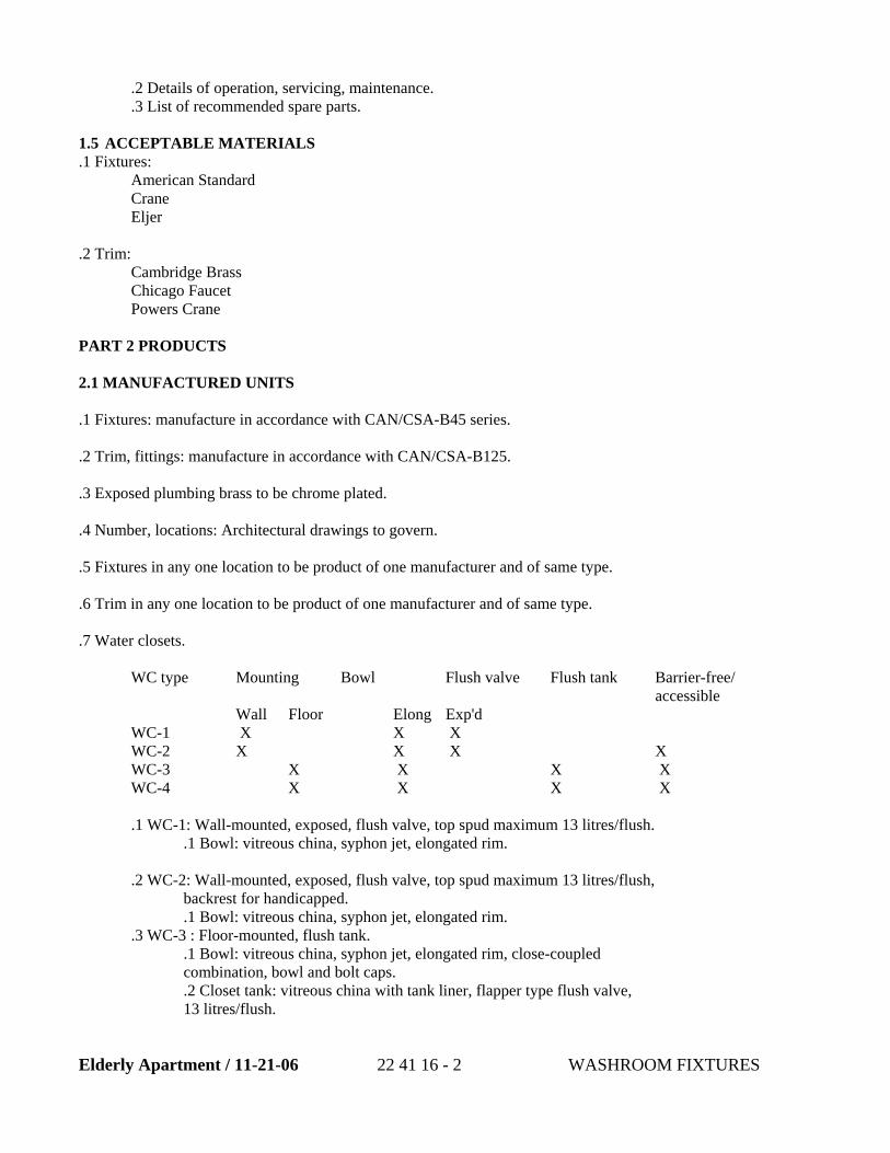
Elderly Apartment / 11-21-06 22 41 16 - 2 WASHROOM FIXTURES
.2 Details of operation, servicing, maintenance.
.3 List of recommended spare parts.
1.5 ACCEPTABLE MATERIALS .1 Fixtures:
American Standard Crane Eljer
.2 Trim: Cambridge Brass Chicago Faucet Powers Crane
PART 2 PRODUCTS 2.1 MANUFACTURED UNITS .1 Fixtures: manufacture in accordance with CAN/CSA-B45 series. .2 Trim, fittings: manufacture in accordance with CAN/CSA-B125. .3 Exposed plumbing brass to be chrome plated. .4 Number, locations: Architectural drawings to govern. .5 Fixtures in any one location to be product of one manufacturer and of same type. .6 Trim in any one location to be product of one manufacturer and of same type. .7 Water closets.
WC type Mounting Bowl Flush valve Flush tank Barrier-free/ accessible
Wall Floor Elong Exp'd WC-1 X X X WC-2 X X X X WC-3 X X X X WC-4 X X X X .1 WC-1: Wall-mounted, exposed, flush valve, top spud maximum 13 litres/flush.
.1 Bowl: vitreous china, syphon jet, elongated rim.
.2 WC-2: Wall-mounted, exposed, flush valve, top spud maximum 13 litres/flush, backrest for handicapped. .1 Bowl: vitreous china, syphon jet, elongated rim.
.3 WC-3 : Floor-mounted, flush tank. .1 Bowl: vitreous china, syphon jet, elongated rim, close-coupled combination, bowl and bolt caps. .2 Closet tank: vitreous china with tank liner, flapper type flush valve, 13 litres/flush.
Elderly Apartment / 11-21-06 22 41 16 - 3 WASHROOM FIXTURES
.4 WC-4 : Floor-mounted, flush tank, for barrier-free/accessible. .5 Alternative types 2 and 4 may be the same as types 1 and 3 with 50mm lift seats
to achieve barrier-free mounting height. .1 Top of seat to be between 400 mm and 460 mm from finished floor. .2 Bowl: vitreous china, floor mounted, syphon jet, elongated rim, closecoupled, bolt caps. .3 Closet tank: vitreous china with tank liner, flapper type flush valve 13 litres/flush.
.8 Water Closet Flush Valves
.1 Quiet action, externally adjustable exposed diaphragm flush valve
.2 For water closets with NPS 1 ½ top spud.
.3 Maximum 292 mm from centerline of valve inlet to top of water closet, except trap seal models which are maximum 298 mm .4 Polished chrome plated finish .5 Vandal resistant cover screw .6 Metal “non hold open” oscillating handle .7 NPS 1 FIP/Copper sweat inlet adaptor .8 Adjustable 121 mm plus or minus 11 mm inlet/valve outlet centers .9 Vacuum beaker .10 88 mm dia. cover tube and wall flange .11 Renewable seat .12 Chloramine resistant diaphragm attached to guide with forged metal retainer. .13 Spud flange and concealed spud nut. .14 Pressure loss check angle stop with protecting cap. .15 6 Litre Factory set flush – field adjustable.
.9 Water Closet Seats and Backrests
.1 Seat: white, elongated , open front, moulded solid plastic, less cover, stainless steel check hinges, stainless steel or solid brass insert post. For handicapped closets include cover.
.10 Urinals
.1 U-1 : Wall-mounted, 6 litres flush, exposed flush valve, top spud. .1 Urinal: vitreous china, washout type, integral flushing rim, extended shields, integral trap, removable stainless steel strainer, back outlet for concealed arm carrier.
.2 U-2 : Wall-mounted, back spud, flush tank, exposed flush piping. .1 Urinal: vitreous china, washout type, integral flushing rim, extended shields, integral trap, removable stainless steel strainer, back outlet for concealed arm carrier. .2 Flush tank: vitreous china, 13 litres, with tank liner, concealed cover, bottom supply connection, and chrome plated exposed flush pipe assembly, automatic syphon valve assembly for ultra low flush cycle: set to 3.8 litres/flush urinal.
.3 UFV-1 Urinal Flush Valves .1 Quiet action, exposed diaphragm flush valve .2 For flushing urinals with NPS 3/4 top spud.
Elderly Apartment / 11-21-06 22 41 16 - 4 WASHROOM FIXTURES
.3 Maximum 330 mm from centerline of valve inlet to top of urinal except trap seal models which are maximum 315 mm. .4 External water conserving flush volume adjustment.
.5 Polished chrome plated finish.
.6 Vandal resistant cover screw.
.7 Metal “not hold open” oscillating handle.
.8 NPS 1 FIP/NPS ¾ copper sweat inlet adaptor
.9 Adjustable 121 mm plus or minus 11 mm inlet/valve outlet centers
.10 Vacuum beaker
.11 38 mm dia. cover tube and wall flange
.12 Renewable seat
.13 Chloramine resistant diaphragm attached to guide with forged metal retainer. .14 Spud flange and concealed spud nut. .15 Pressure loss check angle stop with protecting cap. .16 Factory set for 2.7 L flush-field adjustable.
.4 UFV-2 Urinal Electronic Flush Valves for Public Washrooms and as indicated. .1 Safe 24 volt infrared electronic activated concealed flush valve system. .2 Fixed program-automatic 8 second blocking time. .3 Field adjustable “flush delay” setting of 0 to 6 seconds-factory set at 3 seconds for toilet units and at 0 seconds for urinal units. .4 Field adjustable flush volume using regulating screw on flush valve power function light.
.5 Field adjustable sensing distance 178 mm to 1219 mm factory set to approximately 812 mm. Based on KODAK grey card R27 90% reflective. .6 Modular junction box. .7 Slow closing solenoid valve. .8 Transformer 120-24 VAC. .9 Chloramine resistant diaphragm attached to guide with forged metal retainer. .10 Quiet action concealed diaphragm flush valve .11 Renewable seat. .12 External water conserving flush volume adjustment. .13 Adjustable 121 mm plus or minus 11 mm inlet/valve outlet centers. .14 Vacuum breaker .15 Wheel handle angle pressure loss check stop. .16 NPS 1 FIP/copper sweat inlet adaptor. .17 6 litre factory set flush – field Adjustable .18 Sensor mounted on 356 mm square stainless steel cover .19 305 mm recessed wallmount metal frame. .20 Vandal resistant stainless steel spanner screws.
.11 Washroom Lavatories
.1 L-1: Wall-hung, integral back: .1 Vitreous china, with splash lip, soap depressions, supply openings on 100 mm centres, overflow, for concealed arm carrier. Size: 500 x 450mm. .2 L-2: Counter-top: .3 Vitreous China, self-rimming, with front overflow, soap depressions, gasket, swivel clamps, semi-oval or rectangular bowl, supply openings
on 100 mm centres. Sizes: 475 x 400 mm outside, 400 x 250 x 180 mm
Elderly Apartment / 11-21-06 22 41 16 - 5 WASHROOM FIXTURES
nominal inside. .4 L-3 : wall-hung, for accessible/barrier-free. .5 Vitreous china, low shelf, with integral back, contoured front, shallow front basin, front overflow, soap depressions, supply openings on 300
mm centres, concealed arm carrier. Sizes: 675 x 500 mm. .6 L-4: counter-top: .7 Stainless steel grade 18-8 type 302, Self-rimming, radius bowl corners, hold down clamping, hole drilling to suit faucet, undercoated, integral overflow.
.12 Washroom Lavatory Trim.
.1 LT-1 .1 102 mm two handle, cast brass centerset .2 Polished chrome plated finish. .3 Heavy duty brass compression structures. .4 90% flow with first ¼ turn of operation, 1800. .5 Positive shutoff even in poor water conditions. .6 Metal hold-down package. .7 Centerset with cast open grid strainer no pop-up hole-2 hole installation. .8 Aerator 8.3 L/min. vandal resistant. .9 102 mm blade handles -sanitary hood- metal-color indexed vandal resistant screws.
.2 LT-2 .1 Single handle kitchen deck faucets for exposed mounting on single, three and four hole sinks. .2 Solid brass fabricated body. .3 203 mm long spout swings 3600. .4 Vandal resistant aerator. .5 Vandal resistant 152 mm elbow handle. Red/blue colored graphics indicate hot/cold temperature. .6 Control mechanism to be of the rotating stainless steel ball type with replaceable non-metallic seats operating in stainless steel lined sockets. .7 Control handle to return to neutral position when valve is turned off. .8 Adjustable handle limit stop.
.3 LT-3 Wheelchair supply fitting with cast brass gooseneck spout, aerator, waste fitting: open grid strainer. .1 Hard wire. .2 Infrared electronic handwash system. .3 Chrome plated one piece cast main body with integral sensor. .4 Field adjustable water resistant program controller. .5 Backlit indicator adjustment buttons. .6 Unit retains adjusted settings in event of power failure. .7 Chrome plated forged brass solenoid valve with Y strainer cleanout. .8 Water flows when sensor is activated. .9 Water flow stops at the selected run-on time after user removes hands from sensing zone. .10 Run on time selections are 0 to 8 seconds or 1 to 8 minutes for scrub-up applications. Factory set to 8 seconds.
.11 Blocking time between uses has selectable range of 0 to 8 seconds.
Elderly Apartment / 11-21-06 22 41 16 - 6 WASHROOM FIXTURES
Factory set to 0 seconds. .12 Auto shut-off feature that is selectable between 1 to 9 minutes. Factory set to 1 minute. .13 Metered program mode with selection of 7 to 240 seconds of continuous operation. .14 Adjustable sensing distance from 76 mm to 356 mm factory set to 229 mm sensor ranges are +/- 25 mm subject to environmental conditions based on Kodak grey card R27 90% reflective. .15 110 to 24 VAC Transformer for hardwire models. .16 Gooseneck 150 mm radius 305 mm height (unmounted)-rigid/swivelvandal resistant 2.3 mm wall thickness. .17 Vandal resistant 1.9 L/min aerating outlet. .18 Single hole deckmount gooseneck spout with integral sensor in base. .19 Factory assembled in recessed mounting 250 mm metal box with stainless steel cover – includes mechanical mixing valve with thermostatic limit stop.
.4 LT-4 Washroom Lavatory Electronic Trim for Public Washrooms and as indicated. .1 Hard wire. .2 102 mm electronic faucet. .3 Cast one-piece body with integral waterproof sensor and connector. .4 DMD self-adaptive technology no external adjustments required. .5 Serviceable filter screen upstream of solenoid valve. .6 Metal hold-down package. .7 Hands free (touchless) operation. .8 Water flows when sensor is activated. .9 Water flow stops upon de-activation of sensor. .10 Sensing zone approximately 178 mm. .11 Pre-set 45 second maximum run time. .12 Will reset once obstruction is removed. .13 110 to 24 VAC transformer. .14 Chrome finish. .15 102 mm cast lavatory faucet. .16 Vandal resistant (3.8 L/min.) flow control non-aerating spray outlet. .17 Factory assembled in recessed mounting 250 mm metal box with stainless steel cover- includes mechanical mixing valve with thermostatic limit stop.
.13 Fixture piping. .1 Hot and cold water supplies to fixtures:
.1 Chrome plated flexible supply pipes with screwdriver stop, reducers, escutcheon.
.2 Waste: .1 Brass P trap with cleanout on fixtures not having integral trap. .2 Chrome plated in exposed places.
.14 Chair carriers. .1 Factory manufactured floor-mounted carrier systems for wall-mounted fixtures.
Elderly Apartment / 11-21-06 22 41 16 - 7 WASHROOM FIXTURES
PART 3 EXECUTION 3.1 INSTALLATION .1 .1 Mounting heights:
.1 Standard: to comply with manufacturer's recommendations unless otherwise indicated or specified. .2 Wall-hung fixtures: as indicated, measured from finished floor. .3 For barrier-free washrooms: to comply with most stringent of either NBCC or CAN/CSA B651, or Provincial Building Accessibility Act and Regulations.
3.2 ADJUSTING .1 Conform to water conservation requirements specified this section.
.1 Adjustments. .1 Adjust water flow rate to design flow rates. .2 Adjust pressure to fixtures to ensure no splashing at maximum pressures. .3 Adjust flush valves to suit actual site conditions. .4 Adjust urinal flush timing mechanisms. .5 Automatic flush valves for urinals and lavatories: set controls to prevent unnecessary flush cycles during silent hours.
.2 Checks. .1 Water closets, urinals: flushing action. .2 Aerators: operation, cleanliness. .3 Vacuum breakers, backflow preventers: operation under all conditions.
.3 Thermostatic controls. .1 Verify temperature settings, operation of control, limit and safety controls.
END OF SECTION
SECTION 23 31 00
HVAC DUCTS AND CASINGS PART 1 – GENERAL 1.01 SECTION INCLUDES
A. Sheet metal ductwork.
B. Registers, grilles, and diffusers.
C. Electric duct heaters.
D. Manual volume dampers.
E. Fire dampers.
F. Combination fire/smoke dampers.
G. Back draft dampers.
H. Access doors.
I. Hangers and supports.
J. Sealants.
K. Duct plenums.
L. Flexible connections.
M. Air extractor.
N. Turning vanes.
O. Casings.
P. Fibrous glass ducts.
Q. Kitchen hood exhaust ductwork. 1.02 RELATED SECTIONS
A. Access doors in walls and ceilings shall be as specified in Section 08 31 00 - Access Doors and Panels.
Elderly Apartment / 11-20-06 23 31 00 HVAC DUCTS AND CASINGS
B. Painting of mechanical equipment and components shall be as specified in
Section 09 91 00 -Painting. C. Duct seismic restraints shall be as specified in Section 20 30 13 - Vibration
Isolation and Seismic Control for Facility Services
D. Ductwork insulation shall be as specified in Section 20 07 13 - Plumbing and HVAC Insulation.
E. Electric duct heaters are specified in Section 23 81 00 - Unitary HVAC
Equipment.
F. HVAC system balancing is specified in Section 23 05 93 - Testing, Adjusting, and Balancing for Facility Services
G. Door Louvers are specified in Section 08 11 00 - Metal Doors and Frames.
1.03 MEASUREMENT AND PAYMENT
A. General: Separate measurement or payment will not be made for the Work required under this Section. All costs in connection with the Work specified herein will be considered to be included or incidental to the work of this Contract.
1.04 REFERENCES
A. Air Diffusion Council (ADC):
1. AMCA 500 Test Method for Louvers, Dampers and Shutters
2. ADC1062: GRD Test Code for Grilles, Registers and Diffusers
3. ARI 650 Air Outlets and Inlets
B. American Society of Heating, Refrigerating and Air Conditioning Engineers Inc. (ASHRAE):
1. ASHRAE Handbook, HVAC Applications
2. ASHRAE Handbook, Fundamentals 3. ASHRAE Handbook, HVAC Systems and Equipment
C. American Society for Testing and Materials (ASTM):
1. ASTM A36/A36M Specification for Structural Carbon Steel
Elderly Apartment / 11-20-06 23 31 00 HVAC DUCTS AND CASINGS
2. ASTM A90 Weight of Coating on Zinc-Coated (Galvanized) Iron or Steel Articles
3. ASTM A123 Specification for Zinc (Hot-Dip Galvanized) Coatings on
Iron and Steel Products
4. ASTM A153/ Specification for Zinc Coating (Hot-Dip) on Iron and Steel
5. A153M Hardware 6. ASTMA 525 General Requirements for Steel Sheet, Zinc-Coated
(Galvanized) by the Hot-Dip Process
7. ASTM A653/ Specification for Steel Sheet, Zinc-Coated (Galvanized) or 8. A653M Zinc-Iron Alloy-Coated (Galvanized) by the Hot-Dip Process
D. American Welding Society (AWS):
1. AWS D1.1 Structural Welding Code - Steel
2. AWS D9.1 Sheet Metal Welding Code
E. National Fire Protection Association (NFPA):
1. NFPA 90A Standard for the Installation of Air Conditioning and
Ventilating Systems 2. NFPA 90B Installation of Warm Air Heating and Air Conditioning
Systems
3. NFPA 92A Smoke Control System
F. Sheet Metal and Air Conditioning Contractors National Association Inc. (SMACNA): 1. SMACNA Ducted Electric Heat Guide for Air Handling Systems
2. SMACNA Fire, Smoke and Radiation Damper Installation Guide for
HVAC Systems
3. SMACNA HVAC Air Duct Leakage Test Manual 4. SMACNA HVAC Duct Construction Standards - Metal and Flexible
5. SMACNA HVAC Systems Duct Design
Elderly Apartment / 11-20-06 23 31 00 HVAC DUCTS AND CASINGS
6. SMACNA HVAC Duct Systems Inspection Guide
7. SMACNA Seismic Restraint Manual Guidelines for Mechanical Systems
G. Underwriters Laboratories Inc. (UL):
1. UL 33 Heat Responsive Links for Fire-Protection Service
2. UL 181 Factory-Made Air Ducts and Air Connectors
3. UL 555 Fire Dampers 4. UL 555S Leakage Rated Dampers for Use in Smoke Control Systems
H. UML and California Mechanical Code
1.05 REGULATORY REQUIREMENTS
A. Refer to Section 20 10 13 - Common Materials and Methods for Facility Services – Fire Suppression, Plumbing and HVAC, for requirements.
1.06 SUBMITTALS
A. General: Refer to Section 01 33 00 - Submittal Procedures, and Section 01 33 23 Shop Drawings, Product Data, and Samples, for submittal requirements and procedures.
B. Shop Drawings: Submit Shop Drawings showing the following information:
1. Ductwork layout including diffusers, registers and grilles; 2. Fire damper installation details and locations; 3. Access door installation details and locations; 4. Duct sizes, materials, sheet metal gages, duct reinforcement schedules,
duct supports, duct support spacing, and fabrication methods; and
5. Volume dampers, motorized dampers, turning vanes, and extractors, installation details and locations.
C. Product Data: Submit manufacturers' product data and certificates of compliance
for specified materials and equipment.
Elderly Apartment / 11-20-06 23 31 00 HVAC DUCTS AND CASINGS
D. Test Reports: Submit certified field test reports verifying successful air duct leak testing.
E. Operation and Maintenance Data: Submit operation and maintenance data, for the
equipment provided, in accordance with Section 01 78 23 - Operation and Maintenance Data.
1.07 QUALITY ASSURANCE
A. Provide fabricated duct systems complete as shown on drawings. Duct sizes,
types, routing, and locations shall be as indicated. B. Ductwork shall conform to the applicable requirements of NFPA 90A and NFPA
90B, SMACNA and ASHRAE Handbooks, the California Mechanical Code, Chapter 10, and the equipment manufacturer's recommendations.
C. Duct sizes shall refer to the inside clear dimensions. For acoustically lined or
internally insulated ducts, duct sizes shall be increased to provide clear inside dimensions indicated, with interior surface of unlined duct aligned with inside surface of liner or internal insulation at transition point.
D. Change in duct size or shape necessitated by interference with other work shall be
made using sizes of equivalent friction loss. E. Where pipe, structural member, or other obstruction passes through a duct,
provide a streamlined sheet metal collar around member and increase duct size to maintain net area. Fit collar and calk to make airtight.
F. Galvanized surfaces damaged by welding shall be repaired in accordance with
manufacturer's written instructions. G. Submit detailed fabrication drawings of ductwork showing dimensions,
construction, welding, fittings, and configurations, and receive approval prior to start of work.
H. Qualify welding processes and welding operators in accordance with AWS D1.1
for hangers and supports, and AWS D9.1 for sheet metal. 1.08 DELIVERY, STORAGE, AND HANDLING
A. Duct sections shall be covered and stored on skids above grade. B. Duct sections that come in contact with dirt shall be cleaned inside and outside.
1.09 SITE CONDITIONS
Elderly Apartment / 11-20-06 23 31 00 HVAC DUCTS AND CASINGS
A. Inspect surfaces and structures where air distribution and duct system will be installed before the work of this Section begins. Provide surfaces and structures capable of supporting the system and its weight.
B. Coordinate the installation of the air distribution and duct system with other
building systems and components so as to avoid conflicts of installation. Drawings are diagrammatic and not necessarily to scale.
PART 2 - PRODUCTS 2.01 SHEET METAL DUCTWORK
A. Ducts shall be designed and constructed in accordance with SMACNA HVAC
Systems Duct Design and HVAC Duct Construction Standards of lock forming quality galvanized steel sheet conforming with ASTM A653/A653M, ASTMA525, A527 with zinc coating G90 for each side of sheet, unless otherwise indicated.
B. Ducts embedded in concrete shall be constructed of 1/4-inch thick carbon steel
plate, and shall be welded in accordance with AWS D1.1. Fabricated ducts shall be hot-dip galvanized after fabrication in accordance with ASTM A123 and shall be structurally reinforced. Zinc coating designation shall be G90.
C. Duct fabrication, metal gages, and reinforcement shall conform with the
SMACNA HVAC Duct Construction Standards - Metal and Flexible. Pressure classification of sheet metal ducts shall be two inches water gage, negative or positive, as appropriate, except that ductwork in subways shall be classified at 6 inches of water gage, positive or negative, whichever is more stringent.
D. Provide 300 Series (18-8) stainless steel ductwork for battery room exhaust
system and for ductwork passing through battery rooms. E. Design and fabricate ductwork in accordance with the following requirements:
1. Size round ducts installed in place of rectangular ducts from ASHRAE
table of equivalent rectangular and round ducts. No variation of duct configuration or sizes will be permitted without written approval of the Engineer.
2. Duct sizes 19 inches wide and larger that have more than 10 square feet or
unbraced panel shall be beaded or cross-broken unless ducts will have insulation covering or acoustical liner. This requirement is applicable to 20 gage or less thickness and pressure class of 3 inches water gage or less. It is not necessary to break or bead all sides unless each duct dimension requires it.
Elderly Apartment / 11-20-06 23 31 00 HVAC DUCTS AND CASINGS
3. Lap metal ducts in direction of airflow. Hammer down edges and slips to leave a smooth duct interior. Seal duct seams and joints in accordance with the California Mechanical Code.
4. Construct tees, bends, and elbows with radius of not less than 1.5 times
width of duct on centerline. Where not possible and where rectangular elbows are used, provide airfoil type galvanized steel turning vanes. Where acoustical lining is indicated, provide turning vanes of perforated metal with glass fiber insulation.
5. Increase duct sizes gradually, not exceeding 15 degrees divergence
whenever possible. Maximum divergence upstream of equipment shall be 30 degrees and convergence downstream shall be 45 degrees.
6. Rigidly construct metal ducts with joints air tight, braced and stiffened so
as not to breathe, rattle, vibrate, or sag. Calk duct joints and connections with sealant as ducts are being assembled.
7. Modify ducts where ductwork conflicts with piping and structures. Where
modifications result in duct area reductions exceeding 10 percent duct area, split into two ducts maintaining original duct pressure losses.
8. Provide necessary baffling in mixed air plenums to ensure good mixed air
temperature with variations of not more than plus or minus 2 degrees F under operating conditions.
9. Construct plenums of galvanized panels joined by standing seams on
outside of casing riveted or bolted on approximately 12 inch centers. Reinforce with steel angles and provide diagonal bracing. Tightly fit at apparatus and seal with sealant.
10. Fabricate continuously welded round and oval duct fittings two gages
heavier than duct gages indicated in SMACNA Standard. Joints shall be minimum 4-inch (100 mm) cemented slip joint, brazed or electric welded. Prime coat welded joints.
11. Provide standard 45 degree lateral wye takeoffs, unless otherwise
indicated, where 90 degree conical tee connections may be used.
12. Provide openings in ductwork and casings where required to accommodate thermometers and controllers. Provide pivot tube openings where required for system testing and balancing, complete with metal cap and spring device or screw to ensure against air leakage. Where openings are provided in insulated ductwork, install insulation material inside a metal ring.
Elderly Apartment / 11-20-06 23 31 00 HVAC DUCTS AND CASINGS
13. Locate ducts with sufficient space around equipment to allow normal operating and maintenance activities.
14. Set plenum doors 6 to 12 inches above floor. Arrange door swings so that
fan static pressure holds door in closed position.
15. Where indicated, connect diffusers and registers to ducts with flexible duct. Provide ducts tested and classified by Underwriters Laboratories, Inc., as Class 1 Air Duct, and labeled in accordance with UL 181. Provide flexible duct installed in fully extended condition free of sags and kinks, using only minimum length required to make connection. Single bends shall have inside angles of not less than 90 degrees. Flexible duct shall not be longer than 5 feet.
16. Do not install duct sealants when temperatures are less than those
recommended by sealant manufacturers.
17. Maintain temperatures during and after installation of duct sealants. 2.02 REGISTERS, GRILLES AND DIFFUSERS
A. Product Requirements:
1. Standard Products: Except as otherwise indicated, provide manufacturer's standard registers, grilles, and diffusers where shown; of size, shape, capacity and type indicated; constructed of materials and components as indicated, and as required for complete installation.
2. Performance: Provide registers, grilles, and diffusers that have, as a
minimum, temperature and velocity traverses, throw and drop, and noise criteria ratings for each size device as listed in manufacturer's current catalogs.
3. Ceiling and Wall Compatibility: Provide registers, grilles, and diffusers
with border styles that are compatible with walls and ceiling systems, and that are specifically manufactured to fit into ceiling module or wall construction with accurate fit and adequate support. Refer to Contract Drawings and Specifications for types of wall construction and ceiling systems.
4. Painting: Registers, grilles, and diffusers shall be finished with a baked
white enamel finish unless otherwise approved.
5. Construction: Registers, grilles, and diffusers shall be factory fabricated of aluminum, plate or extruded. Exposed edges shall be rolled, extruded, or otherwise stiffened. All components shall be product of one manufacturer.
Elderly Apartment / 11-20-06 23 31 00 HVAC DUCTS AND CASINGS
6. Air Distribution: Supply air diffusers and registers shall distribute
specified quantity of air evenly over space intended without causing noticeable draft, air movements faster than 50 fpm in occupied zone, or dead spots anywhere in the ventilated area.
7. Sound Ratings: Inlets and outlets shall be sound rated and certified in
accordance with ADC1062: GRD, in sound power level, decibels reference 10 W - 12 W, in octave bands 2-6. The rated NC sound pressure level index, computed by deducting 8 dB room attenuation, shall not exceed NC-35.
B. Diffusers:
1. Internal parts of each diffuser shall be removable as a unit. Removable parts shall be constructed so that they cannot be reassembled in a manner that will produce an incorrect air distribution pattern. The internal assembly shall be either circular, square, or rectangular and shall be removable and capable of being reassembled without special tools. Sheet metal air duct or plenum connection to diffusers shall be secured in accordance with the diffuser manufacturer's instructions. Sponge rubber or neoprene gasket shall be provided between ceiling and surface mounted diffusers.
2. Provide ceiling diffusers of the rectangular, square, or linear face type as
indicated. Diffusers shall be equipped with baffles to provide the air distribution pattern. Provide factory-fabricated turning-vanes at each diffuser, branch duct and take-off, except where flexible ductwork is used. Vanes shall be removable through the diffuser. Each diffuser shall have a factory-fabricated, single key, opposed blade volume damper constructed so that the required air flow can be obtained without affecting the air distribution pattern; the volume damper key operator shall be operable through diffuser face without removing air distribution baffle.
C. Supply Registers: Provide multi-directional-control type register with a factory-
fabricated volume damper. Volume dampers shall be group-operated, opposed-blade type and shall be key-adjustable. Volume damper adjustment shall be made by inserting key through face of register. Operating mechanism shall not project through the register face. Registers shall be provided with sponge rubber or neoprene gaskets between flanges and wall or ceiling.
D. Exhaust and Return Registers: Exhaust and return registers shall be as specified
for supply registers herein, except provide exhaust and return registers with a single set of fixed, non see through, non-directional face blades or louvers having the same appearance as the supply register.
Elderly Apartment / 11-20-06 23 31 00 HVAC DUCTS AND CASINGS
E. Grilles: Grilles shall be as specified for registers, except without volume control dampers. Exhaust outlets for battery rooms shall be constructed of 316 Stainless Steel.
2.03 ELECTRIC DUCT HEATERS
A. Electric duct heaters shall be flanged type heaters in accordance with applicable requirements of Section 23 81 00 - Unitary HVAC Equipment.
2.04 MANUAL VOLUME DAMPERS
A. Requirements: Provide adjustable balancing dampers of minimum 16 gage galvanized steel construction, conforming with applicable requirements of SMACNA HVAC Duct Construction Standards-Metal and Flexible, with locking quadrants. Manually adjustable balancing dampers shall be provided at points on supply systems where branches are taken from larger ducts and in branch duct to individual diffusers, grilles, and registers, as required for air balancing.
1. Damper axles shall be continuous square rods not smaller than 3/8-inch,
with Machined ends and bearings at both ends. Damper blades shall not be more than six inches wide by 48 inches long.
2. Single-blade dampers shall be provided for duct sizes up to 9-inches by
30-inches. Multi blade dampers of opposed blade pattern shall be provided for duct sizes larger than 9- inches by 30-inches.
B. End Bearings: Except in round ductwork 12 inches (300 mm) and smaller,
provide end bearings. On multiple blade dampers, provide oil-impregnated nylon or sintered bronze bearings.
C. Quadrants:
1. Provide locking, indicating quadrant regulators on single and multi-blade dampers.
2. On insulated ducts, mount quadrant regulators on stand-off mounting
brackets, bases, or adapters.
3. Where rod lengths exceed 30 inches (750 mm) provide regulator at both ends.
D. Splitter Dampers: Provide only where indicated. Splitter dampers shall be
constructed ofdouble thickness galvanized steel sheet shaped to streamline and stiffened to avoid vibration. Splitter dampers shall be sized on the basis of straight air volume proportioning, and shall be operated by quadrant operators.
Elderly Apartment / 11-20-06 23 31 00 HVAC DUCTS AND CASINGS
2.05 FIRE DAMPERS
A. Fire dampers shall be UL Class A rating and constructed in accordance with UL 555S and SMACNA Fire, Smoke and Radiation Damper Installation Guide for HVAC Systems. Fusible links on fire dampers shall be constructed in accordance with UL 33. Provide fire dampers in accordance with NFPA 90A where ducts and outlets pass through fire-rated walls, and where indicated. Fire damper assembly shall be complete with required perimeter mounting angles, sleeves, breakaway duct connections, and stainless steel springs, bearings, bushings, and hinges.
B. Fire dampers shall be curtain type and fabricated of galvanized steel, weighted to
close and remain in closed position when released by fusible link. Fabricate fire dampers with linkage readily adjustable with damper in open position. Curtain type fire dampers shall have blades retained in a recess so free area of connecting ductwork is not reduced. Fire dampers shall have the same (or higher) fire rating as the fire rated walls where ducts pass through.
C. Set or select fusible links for 165 degrees F release unless otherwise indicated.
2.06 COMBINATION FIRE/SMOKE DAMPERS
A. Provide fire and smoke combination dampers in accordance with UL 555S,
Leakage Class II, with a leakage rating of not more than ten cfm per square foot at one-inch water gage pressure differential across closed damper. Provide two-position dampers, equipped with an electric damper operator and with firestat that electrically locks damper in a closed position when ambient (duct) temperatures exceed 165 degrees F.
B. Damper shall be capable of interfacing electrically with a smoke detector and
remote indicating/control station. Where indicated, provide conventional fusible link connection between damper and operator instead of a firestat.
2.07 BACKDRAFT DAMPERS
A. Provide 16-gage aluminum, multiblade, gravity type, backdraft dampers having balanced parallel action, 1/2 inch steel axles spaced 9- inch centers, with 1/2 inch ball bearings, blades, and flexible vinyl sealing edges. Weighted relief dampers shall be used where it is required to maintain positive pressure by forced air supply and gravity exhaust.
2.08 ACCESS DOORS
A. Provide access doors or panels for maintenance of filters and coils, control
dampers, on either side of each fire and smoke damper, and at thermostats, temperature controllers, and other apparatus requiring service and inspection.
Elderly Apartment / 11-20-06 23 31 00 HVAC DUCTS AND CASINGS
Locations shall be approved prior to duct fabrication. Fabricate rigid, close-fitting doors of galvanized steel with sealing gaskets and quick fastening locking devices. For insulated ductwork, install minimum one-inch thick insulation with sheet metal cover. Provide two hinges and two sash locks for sizes up to 18 inches high, two hinges and two compression latches with outside and inside handles for sizes up to 24 by 48 inch. Height of access doors shall be 4 to 6 inches smaller than the duct dimension by 16 inches wide, but not less than 6 inches by 8 inches. Provide an additional hinge for larger sizes. Refer to Section 08 31 00 - Access Doors and Panels, for detailed requirements for wall and ceiling mounted access doors and panels to access concealed ducts.
B. Access doors in plenums of air-conditioning systems shall be hinged and
furnished with latches operable from both inside and outside. Edges shall rest against neoprene or felt for airtight closure. Plenum access doors shall open to the outside of housing on the fan section side and to the inside on the fan discharge side.
2.09 HANGERS AND SUPPORTS
A. Requirements: Provide hangers and supports of steel shapes and rods conforming
to ASTM A36/A36M, galvanized in accordance with ASTM A123. Hardware for hangers and supports shall be galvanized in accordance with ASTM A153/A153M. Hangers and supports shall be fabricated in accordance with SMACNA HVAC Duct Construction Standards - Metal and Flexible, and SMACNA HVAC Systems Duct Design.
B. Building Attachments: Concrete inserts, powder-actuated fasteners, or structural
steel fasteners appropriate for building materials. Do not use powder-actuated concrete fasteners for lightweight aggregate concretes or for slabs less than 4 inches thick.
C. Hangers: Galvanized sheet steel, or round, uncoated steel, threaded rod. D. Straps and Rod Sizes: Conform with Table 4-1 in SMACNA HVAC Duct
Construction Standards - Metal and Flexible, for sheet steel width and gage and steel rod diameters.
E. Duct Attachments: Sheet metal screws, blind rivets, or self-drilling, self-tapping
metal screws; compatible with duct materials. F. Longitudinal and Transverse Seismic Bracing of Ductwork: Conform to
SMACNA Seismic Restraint Manual Guidelines for Mechanical Systems and ASHRAE Handbook, HVAC Applications, Chapter 50, except base the design of restraints on a force equal to 100 percent of the weight of the ductwork acting in either direction.
Elderly Apartment / 11-20-06 23 31 00 HVAC DUCTS AND CASINGS
2.10 SEALANTS A. Provide as specified in Section 07 90 00 - Joint Protection, with sealants
conforming to SMACNA HVAC Duct Construction Standards - Metal and Flexible.
2.11 DUCT PLENUMS
A. Provide duct plenums fabricated in accordance with SMACNA HVAC Duct
Construction Standards - Metal and Flexible, Section VI, Equipment and Casings. 2.12 FLEXIBLE CONNECTIONS
A. Provide UL-listed flexible connections conforming to NFPA 90A. Fabric shall be
unpainted glass fiber cloth weighing not less than 32 ounces per square yard. Cloth shall be coated with fire-resistant neoprene on both sides. Flexible portion shall be 6 inches long. Perimeter connection on each end shall be 3 inch wide galvanized sheet steel, and shall be mechanically bonded to the fabric. Fasteners shall be either screws or bolts. Flexible connectors shall be mechanically secured, at both ends, to provide airtight joints.
2.13 AIR EXTRACTOR
A. Where more than one outlet is installed in a duct, and where there is inadequate
space for Installing multi-blade volume damper, an air extractor with locking adjustable quadrant shall be provided, just upstream of each outlet, for noise control and proper diversion of air flow to outlets further downstream. Air extractors shall be movable blade pivoted type. No extractor is required for the last outlet of the system. Extractor and quadrants shall be constructed of galvanized steel.
2.14 TURNING VANES
A. Fabricated Turning Vanes: Provide fabricated single blade, sheet metal turning
vanes and vane runners, constructed in accordance with SMACNA HVAC Duct Construction Standards – Metal and Flexible.
B. Manufactured Turning Vanes: Provide single blade, sheet metal turning vanes
constructed of 1-1/2 inches wide curved blades set at 3/4 inch on centers, supported with bars perpendicular to blades set at 2 inches on centers, and set into side strips suitable for mounting in ductwork.
2.15 CASINGS
A. Fabricate casings in accordance with SMACNA HVAC Duct Construction
Standards – Metal and Flexible and construct for operating pressures indicated.
Elderly Apartment / 11-20-06 23 31 00 HVAC DUCTS AND CASINGS
B. Mount floor mounted casings on 4-inch (100 mm) high concrete curbs. At floor,
rivet panels on 8-inch (200 mm) centers to angles. Where floors are acoustically insulated, provide liner of 18 gage ((1.20) galvanized expanded metal mesh, supported at 12-inch (300 mm) centers, turned up 12 inches (300 mm) at sides with sheet metal shields.
C. Reinforce door frames with steel angles tied to horizontal and vertical plenum
supporting angles. Install hinged access doors where indicated or required for access to equipment for cleaning and inspection. Provide clear wire glass observation ports, minimum 6-inch by 6-inch (150 x 150 mm) size.
D. Fabricate acoustic casings with reinforcing turned inward. Provide 16 gage (1.50
mm) back facing and 22 gage (0.80 mm) perforated front facing with 3/32 inch (2.4 mm) diameter holes on 5/32- inch (4 mm) centers. Construct panels 3 inches (75 mm) thick packed with 4.5 lb/cu ft (72 kg/cu m) minimum glass fiber media, on inverted channels of 16 gage(1.50 mm).
PART 3 - EXECUTION 3.01 INSTALLATION
A. Installation Standards: Ductwork and accessories shall be installed in accordance
with NFPA 90A, ASHRAE Handbook, and SMACNA HVAC Duct Construction Standards - Metal and Flexible, as applicable. Mounting and supporting of equipment, ducts, accessories, and appurtenances shall be provided, including structural supports, hangers, stands, clamps and brackets. Equipment shall be installed in accordance with the manufacturer's installation instructions.
B. Sheet Metal Ductwork: C. Duct Hangers and Supports: 2. Ducts shall be seismically restrained in accordance with requirements of
Section 20 30 13 - Vibration Isolation and Seismic Control for Facility. D. Registers, Grilles, and Diffusers: Registers, grilles, and diffusers shall be installed
only after all ceilings and walls are finished including final painting. Ceiling mounted units shall be installed with rims tight against ceiling. Wall mounted units shall be installed at least 6 inches below the ceiling unless otherwise indicated. Dampers provided with diffusers and registers shall not be used for system balancing. Inside of duct, behind see-through registers and grilles shall be painted black.
E. Flexible Connections: Provide flexible connections located between fans and
ducts and casings and ducts of dissimilar metals.
Elderly Apartment / 11-20-06 23 31 00 HVAC DUCTS AND CASINGS
F. Flashings: Provide flashings where ducts pass through exterior building walls and
roofs. Flashings shall weatherproof the penetration. G. Duct Heaters: Where electric heaters are installed in air ducts, the duct shall be
insulated with non combustible insulation extending in each direction from the heater. Distance shall be as recommended by the heater manufacturer.
3.02 CLEANING
A. After completion of ductwork, the entire system shall be cleaned of rubbish,
plaster, dirt, dust, and other debris. After equipment has been installed and connections have been made, and before grilles, outlets, and registers are installed, the entire system shall be blown out with dampers and outlets wide open. Temporary screens or filters shall be provided to protect equipment during the cleaning operation.
3.03 FIELD QUALITY CONTROL
A. Ductwork and accessories shall be leak tested before installing insulation. Tests
shall be performed in accordance with and at the maximum pressure designation of SMACNA HVAC Air Duct Leakage Test Manual. Joints and seams shall be tested in the presence of the Engineer.
B. Determine leakage from entire system or section of the system by relating leakage
to the surface area of the test section.
C. Maximum allowable leakage shall be as specified in ASHRAE Handbook, Fundamentals, Volume, Chapter 32, Table 6 and Figure 10. Comply with requirements for leakage classification 3 for round and flat oval ducts, leakage classification 12 for rectangular ducts in pressure classifications less than and equal to 2 inches water gage (both positive and negative pressures), and leakage classification 6 for pressure classifications greater than 2 inches water gage and less than and equal to 10 inches water gage.
D. Remake leaking joints as required and apply sealants to achieve tight joints with
less leakage than the maximum allowable leakage.
E. Perform volumetric measurements and adjust air systems as specified in ASHRAE Handbook, HVAC Systems and Equipment; ASHRAE Handbook, HVAC Applications; ASHRAE Handbook, Fundamentals; and Section 23 05 93 - Testing, Adjusting, and Balancing for HVAC
F. Perform inspections, as necessary, to ensure compliance with NFPA standards
and SMACNA HVAC Duct Construction Standards - Metal and Flexible, witnessed by the Engineer. Conduct inspection in accordance with SMACNA
Elderly Apartment / 11-20-06 23 31 00 HVAC DUCTS AND CASINGS
HVAC Duct Systems Inspection Guide. Results of inspections shall be documented and submitted for review.
G. After testing and inspection, system shall be restored to its operating condition.
3.04 ADJUSTING AND BALANCING
A. Refer to Section 23 05 93 - Testing, Adjusting, and Balancing for HVAC, for requirements and procedures for adjusting and balancing air distribution and return systems.
END OF SECTION 23 31 00
Elderly Apartment / 11-20-06 23 31 00 HVAC DUCTS AND CASINGS
Specifications 11/21/2006 23 34 00 HVAC FANS
SECTION 23 34 00
HVAC FANS
PART 1 GENERAL
1.01 SECTION INCLUDES
A. Fans-product requirements.
B. Centrifugal utility fans.
C. Tubular centrifugal fans.
D. Axial vane fans.
E. Powered roof exhaust fans.
F. Gravity roof ventilators.
G. In-line cabinet fans.
H. Propeller fans.
I. Wall exhaust fans.
J. Variable volume units.
1.02 RELATED SECTIONS
A. Painting of mechanical equipment and components shall be as specified in Section 09 91 00 - Painting.
B. Vibration isolation shall be in accordance with Section 20 30 13 - Vibration Isolation and Seismic Control for Facility Services
C. Air distribution ductwork is specified in Section 23 31 00 - HVAC Ducts and Casings.
D. Refer to Facility Design, Criteria, Mechanical, Line Sections Article 6 for Emergency
Ventilation System.
1.03 MEASUREMENT AND PAYMENT
Specifications 11/21/2006 23 34 00 HVAC FANS
A. General: Separate measurement or payment will not be made for the work
required under this included Section All cost in connection with the Work
specified herein will be considered to or incidental to the Work of this Contract.
1.04 REFERENCES
A. Anti-Friction Bearing Manufacturers Association, Inc. (AFBMA):
1. AFBMA 9 Load Ratings and Fatigue Life for Ball Bearings
2. AFBMA 11 Load Ratings and Fatigue Life for Roller Bearings
B. Air Movement and Control Association (AMCA):
1. AMCA 99 Standards Handbook
2. AMCA 210 Laboratory Methods of Testing Fans for Rating
3. AMCA 300 Reverberant Room Method for Sound Testing of Fans
4. AMCA 301 Methods for Calculating Fan Sound Ratings from Laboratory Test
Data
5. AMCA 500 Test Methods for Louvers, Dampers and Shutters
6. ARI 410 Standard for Forced-Circulation air-Cooling and Air-Heating
Coils
7. ARI 430 Standard for Central-Station Air-Handling Units.
8. ARI Guideline D Application and Installation of Central Station Air-Handling
Units
9. ARI 610 Central System Humidifiers
10. NEMA MGI Motors and Generators
11. NFPA 70 National Electrical Code
12. SMACNA HVAC Duct Construction Standards – Metal and Flexible
13. UL 900 Standard for Air Filter Units
Specifications 11/21/2006 23 34 00 HVAC FANS
14. UL Fire Resistance Directory
15. UL 705 Power Ventilation
1.05 REGULATORY REQUIREMENTS:
A. Refer to Section 20 10 13 - Common Materials and Methods for Facility Services – Fire
Suppression, Plumbing and HVAC, for requirements.
1.06 SUBMITTALS A. General: Refer to Section 01 33 00 - Submittal Procedures, and Section 01 33 23 - Shop
Drawings, Product Data, and Samples, for submittal requirements and procedures.
B. Shop Drawings: Submit assembly, erection, and installation drawings. Include foundation,
platform, and curb details as applicable.
C. Product Data: Submit manufacturer's product data for each fan, including fan performance
curves, sound power ratings, and electrical characteristics.
D. Operation and Maintenance Data: Submit manufacturer's operation and maintenance
instructions in accordance with Section 01 78 23 - Operation and Maintenance Data. Include parts
and special tools lists.
E. Test Reports: Submit certified test reports for the fans and field test results for installed
products.
F. Submit Foundation Data.
1.07 QUALITY ASSURANCE
A. Sound Power Level Ratings: Comply with AMCA 301. Test fans in accordance with AMCA
300. Fans shall be licensed to bear the AMCA Certified Sound Ratings Seal.
B. Fan Performance Ratings: Establish flow rate, pressure, power, air density, speed of rotation,
and efficiency by factory tests and ratings in accordance with AMCA 210.
C. Work Quality: Conform to Applicable requirements of AMCA 99.
Specifications 11/21/2006 23 34 00 HVAC FANS
PART 2 - PRODUCTS 2.01 FANS - PRODUCT REQUIREMENTS
A. General: Provide fans that are factory fabricated and assembled, factory tested,
and factory finished, with indicated capacities and characteristics.
B. Fan Wheel: Fan wheels shall be statically and dynamically balanced. Maximum
fan wheel tip speeds shall not exceed manufacturer's designed maximum speed
for required duty. The wheels shall be designed so that the critical speed is at least
25 percent greater than the maximum design speed.
C. Fan Shaft: Turned, ground, and polished steel, designed to operate at no more
than 70 percent of the first critical speed at the top of the speed range of the fan's
class. Secure fan wheel and driving pulley to the shaft with keys and set screws.
D. Pulleys: V-belt drive fans shall be provided with an adjustable pitch motor pulley
up through 10 hp. Pulleys shall be cast steel sized for a 1.2 service factor. Belts
shall be oil resistant, nonsparking, and nonmetric rated for 150 percent of drive
motor horsepower. Drive pulley shall be replaced if necessary to have fan deliver
required air volume.
E. Belt Guards: Provide galvanized steel belt guards for motors mounted on the
outside of the fan cabinet. Belt guards for outdoor units shall be fully enclosed.
F. Shaft Bearings: Provide type indicated, having a median life "Rating Life"
AFBMA (L50) of 200,000, calculated in accordance with AFBMA 9 for ball
bearings and AFBMA 11 for roller bearings.
G. Motors: Motors shall be totally enclosed fan cooled in compliance with Section
20 60 13 - Motors for Facility Services, and shall have electrical ratings as
indicated. Motorshall be mounted on adjustable base for belt driven fans.
Specifications 11/21/2006 23 34 00 HVAC FANS
H. Vibration Isolators: Fan shaft bearing and motor shall be mounted on vibration isolators
to structural steel supports, which shall be attached to the fan scroll or frame. Structural
steel shall be factory coated with Engineer-approved corrosion-resistant coating system.
I. Fan Nameplates: Provide with each fan indicating area served, cfm, hp, rpm, sp, and size
of unit. Nameplates shall be in accordance with Section 20 40 13 - Identification for
Facility Services.
J. Battery Room Exhaust Fans: Provide with explosion-proof motors and spark-proof
construction, AMCA 99-0401, type B. Epoxy coat inside of fan housing.
2.02 CENTRIFUGAL UTILITY FANS
A. Provide factory-manufactured, factory-assembled, and factory tested centrifugal fans complete
with fan wheel, fan shaft, bearings, drive, motor, and accessories as herein specified.
B. Non-overloading type fans shall be of steel construction and shall have fan wheels with
backward inclined steel construction with smooth curved inlet flange or airfoil blades combined
with a heavy backplate and spun wheel cone selected for air flow rates above 4,000 cfm.
Forward curved type fans, steel construction with inlet flange, backplate, shallowblades with
inlet and tip curved forward in direction of air flow selected for air flow rates up to 4,000 cfm,
shall have fan wheels with die-cast blades formed to provide identical exact shapes, and venturi
style inlet cone.
C. Inlet collars shall extend beyond fan housing sufficiently to provide connection to duct through a
flexible connection. Fan inlets shall be double curved and streamlined to provide full smooth
airflow to the wheel.
D. Fan outlets shall be provided with removable angles and bolts for attaching flexible connections.
E. Fan housings shall be constructed of heavy gage steel braced to provide stiffness to housing and
rigid support for bearings. Housings shall be provided with access panels and drain plugs.
Access panels on supply fans located downstream of heating or cooling coils shall be raised type
Specifications 11/21/2006 23 34 00 HVAC FANS
suitable to receive insulation. Housing supports shall be of one-piece welded
construction. Removable galvanized steel screens shall be provided for exposed inlet and
discharge outlet openings into fan housings including fans in built-up plenums.
F. Provide outdoor fans with weather covers for motor and drive. Weather covers shall be
provided with ventilation slots, and finished with weather-resistant baked enamel. Covers
shall be easily removable for inspection and service.
G. Bearings shall be heavy-duty pillow block, self-aligning ball or roller, and antifriction
type.Bearings 4 inches and larger shall have minimum two rows of spherical roller
bearings contained in split pillow block, grease-lubricated ball bearing with ABMA 9
(L10 life at 50,000 hours), or roller bearing ABMA 11 (L10 life at 120,000 hours).
H. Shafts: Hot-rolled steel, ground and polished, with keyway, protectively coated with
lubricating oil and shaft guard.
I. Accessories:
1. Fixed Inlet Vanes: Steel construction with fixed cantilevered inlet guide vanes welded
to inlet bell.
2. Adjustable Inlet Vanes: Steel construction with blades (supported at both ends)
(cantilevered) with two permanently lubricated bearings, variable mechanism (out of air
stream) terminating in single control lever with control shaft for double width fans (and
locking quadrant).
3. Discharge Dampers: (Parallel) (Opposed) blade heavy-duty steel damper assembly
with blades constructed of two plates formed around and welded to shaft, channel frame,
sealed ball bearings, with blades linked out of air stream to single control lever.
4. Inlet/outlet Screens: Galvanized steel, with welded grid.
5. Access Doors: Shaped to conform to scroll, with quick opening latches and gaskets.
6. Scroll Drain: 1/2 inch steel pipe, coupling welded to low point of fan scroll.
Specifications 11/21/2006 23 34 00 HVAC FANS
2.08 PROPELLER FANS
A. Propeller fans shall have wheels constructed of either steel or aluminum blades with
hubs, mounting rings and plates that are cast or die formed, and with smooth curves
where the air enters the wheels.
B. Propeller fans shall be provided complete with motors and fan guards. Fans and motors
shall be mounted on resilient supports and heavy steel frame. Steel angles and plates shall
be provided to mount fans and dampers in wall openings. Mounting plates shall be
designed to prevent distortion and shall be either turned up at edges or braced with steel
angles.
C. Shafts for fans shall be steel. Bearings for fan shafts shall be permanently lubricated,
permanently sealed, ball bearings.
D. Accepting fan wheels mounted on either extended motor shafts or ball-bearing hubs that
rotate on fixed stub shafts, support shafts by two self-aligning bearings.
E. Each unit shall be provided with gravity backdraft damper recessed in the wall, with
aluminum blades, steel frame, mounted on discharge side of fan, of same manufacturer as
fan.
F. Fans shall be belt-driven or direct-driven as indicated. Motor mounting for beltdriven
units shall be resilient and shall be adjustable for correction of belt tension.
G. Propeller fan shall have a motor with nameplate rating not less than the brake horsepower
required to drive the fan with a static pressure 0.20 inch greater than the indicated value.
H. Fan guard (motor side) shall be removable 1/2 inch by 1/2 inch galvanized wire
mesh screen.
Specifications 11/21/2006 23 34 00 HVAC FANS
2.09 WALL EXHAUST FANS
A. Wall exhaust fans shall be low silhouette type complete with spun-aluminum
housing, wheel guard, disconnect switch, and resiliently mounted motor. Drive
assembly shall be mounted on vibration isolators.
B. Ventilator housing shall be spun-aluminum construction and shall be provided
with a rubber grommet internal wiring passage. Exhaust air shall discharge in a
360 degree pattern. Fans shall
be provided with attachment collar or angle ring to receive through-the-wall
sleeve.
C. Fans shall be directly driven backward curved non-overloading centrifugal design.
D. Provide each fan with an aluminum counterbalanced backdraft damper, gravity
activated and 1/2 inch mesh thick aluminum wire bird screen unless otherwise
indicated.
2.10 VARIABLE VOLUME UNITS
A. Basic Assembly:
1. Casings: Minimum 22 gage (0.8 mm) galvanized steel; maximum casing
leakage: 3 percent of design air flow at 6 inches (1.25 kpa) minimum inlet static
pressure.
B. Basic Unit:
Specifications 11/21/2006 23 34 00 HVAC FANS
1. Configuration: Air volume damper assembly and control components inside unit
casing.
2. Volume Damper: Constructed of galvanized steel with peripheral gasket and self
lubricating bearings; maximum damper leakage: 2 percent of design air flow at 3 inches
rated inlet static pressure.
3. Mount damper operator to position damper as indicated.
C. Regulator:
1. Location: Locate air volume damper and automatic flow control assembly inside unit
casing.
2. Construction: Extruded aluminum or 20 gage (0.9 mm) galvanized steel components;
key damper blades into shaft with nylon fitted pivot points.
3. Automatic Flow Control Assembly: Combine spring rates matched for each volume
regulator size with machined dashpot for stable operation.
4. Volume Control Damper: Air volume control damper shall be factory-calibrated
assembly, consisting of damper and damper shaft extension for connection to externally
mounted control actuator.
5. Internally mounted electric actuator with pilot positioner: Position damper as
(normally) indicated.
D. Multi Outlet Adapter Section: Provide with 8-inch (200 mm) diameter collars, each with
butterfly balancing damper with lock.
E. Hot Water Heating Coil:
1. Construction: ½ inch (13 mm) copper tube mechanically expanded into aluminum
plate fins, leak tested under water to 200 psig (10380 kPa) pressure, factory installed.
Specifications 11/21/2006 23 34 00 HVAC FANS
2. Capacity: Based on 180 degrees F entering water, 160 degrees leaving water
and 50 percent total air volume.
F. Electric Heating Coil:
1. Constriction: UL listed, slip-in type, open coil design, integral control box
factory wired and installed, with:
a. Primary and secondary over-temperature protection.
b. Minimum airflow switch.
c. Electric switches and relays. Magnetic contactor for each step of
control.
G. Automatic Damper Operator:
1. Electric Actuator: 24 volt with remote temperature read and reset capability.
2. Lining: Minimum 3/4 inch (19 mm) thick neoprene or vinyl coated fibrous
glass insulation, 1.5 lb/cu ft (24 g/l) density, meeting NFPA 90A requirements
and UL 181 erosion requirements.
3. Plenum Air Inlets: Round stub connections for duct attachment.
4. Plenum Air Outlets: S slip and drive connections.
PART 3 - EXECUTION
3.01 INSTALLATION
A. Install fans level and plumb, in accordance with manufacturer's installation
instructions. Support units as herein specified, using the vibration control devices
as specified in Section 20 30 13 - Vibration, Isolation and Seismic Control for
Facility Services. Secure fans with galvanized or cadmium-plated hardware.
Provide supporting steel, mounting curbs, and anchorage devices as required to
properly support the unit.
Specifications 11/21/2006 23 34 00 HVAC FANS
B. Install suspended units independently from building structure using threaded steel rods
and vibration isolators, unless otherwise indicated.
C. Rigidly anchor roof-mounted units to roof curbs using galvanized or cadmium-plated
hardware.
D. Make final connections to ductwork using flexible connectors. Secure flexible duct
connectors mechanically to fan and duct to provide airtight joints. Install 1/2-inch mesh
bird screen on discharge of weather hood downstream from discharge shutter.
3.02 START-UP SERVICE
A. Provide the services of a factory-authorized service representative to inspect the
installation and connections and to provide initial start-up service. Services shall include
a complete operational check and demonstration of the equipment operation to ensure
proper operation.
3.03 TRAINING: Provide instructions to the District's maintenance personnel on proper
operation and maintenance procedures in accordance with Section 01 79 00 -
Demonstration and Training.
3.04 FIELD QUALITY CONTROL
A. Perform start-up tests of air-handling units for proper operation of motor, drive system,
and fan wheel. Adjust fan to indicated RPM. Replace fan and motor pulleys as required
to achieve design conditions. Measure and record motor electrical values for voltage and
amperage. Shut unit down and reconnect automatic temperature control operators as
applicable. Perform tests in accordance with the respective manufacturer's instructions
and applicable codes and standards.
B. The Engineer will review certificates of compliance and test reports, and witness all tests.
Specifications 11/21/2006 23 34 00 HVAC FANS
Submit certified test results as specified in Article 1.06 herein.
C. Refer to Section 23 05 93 - Testing, Adjusting, and Balancing for HVAC, for air
handlingsystem testing, adjusting, and balancing requirements and procedures.
END OF SECTION 23 34 00
Elderly Apartment / 11-21-06 23 52 00 - 1 Heating Boilers
SECTION 23 52 00
HEATING BOILERS
PART 1 GENERAL
1.01 SECTION INCLUDES:
A. Section Includes:Immersion Fired Hot Water Boilers.
1.02 RELATED SECTIONS:
A. Section 23 51 00 - Breechings, Chimneys, and Stacks.
B. Section 23 09 00 – Instrumentation and Control for HVAC.
1.03 REFERENCES
A. American Society of Mechanical Engineers (ASME):
1. ASME BPVC-CC-N, Boiler and Pressure Vessel Code IV, 2004.
B. Industrial Risk Insurers (IRI).
C. National Board of Boiler and Pressure Vessel Inspectors (NBBI).
D. National Fire Protection Association (NFPA):
1. NFPA 54 National Fuel Gas Code.
2. NFPA 70 National Electric Code.
E. Underwriters Laboratories, Inc. (UL):
1. UL 795 Commercial-Industrial Gas Heating Equipment.
1.04 DELIVERY, STORAGE & HANDLING
A. General: Comply with Division 01 Product Requirements.
B. Ordering: Comply with manufacturer’s ordering instructions and lead time requirements to avoid construction delays.
C. Delivery, Storage and Protection:
1. Store boiler to allow for drainage and to prevent ponding of water.
2. Allow proper ventilation to prevent condensation.
3. Properly brace boiler while storing.
Elderly Apartment / 11-21-06 23 52 00 - 2 Heating Boilers
4. Inspect boiler and components for damage.
1.05 ENVIRONMENTAL REQUIREMENTS
A. No Environmental Requirements
PART 2 PRODUCTS
2.01 HOT WATER BOILER
A. Manufacturer: Sellers Engineering Company.
1. Contact: 918 W Walnut St., Danville, KY 40422-1359; Telephone: (800) 422-3036, (859) 236-3181; Fax: (859) 236-3184; website: www.sellersengineering.com.
B. Proprietary Products/Systems: Sellers Model 8001, Immersion Fired Hot Water Boilers with XID Enhancement.
1. Packaged Boilers:
a. Output of [_______] Btu/hour at nozzle when fired with natural (LP) gas with minimum pressure of [_____] psi ([____] kPa).
b. Built to requirements of ASME Boiler and Pressure Vessel Code for maximum allowable working pressure of [_____] psi ([____] kPa).
c. Maximum Overall Dimensions: [____ inches (mm)] wide × [_____inches (mm)] long × [_____inches (mm)] high with heavy duty structural steel skid base.
d. Factory assembled and wired to require only supply, return, drain, fuel, vent and electrical connections.
e. Single pass immersion fired design. Ligaments between tubes minimum 1 inch (25.4 mm).
f. In-tube heat extractors/flame stabilizers: stainless steel.
1) Acceptable Material: Heat extractors/flame stabilizers, ENERGY X-TRACTORS manufactured by Sellers Engineering Company.
g. Front and rear tube sheets and flues fully accessible for inspection or cleaning when doors are swung open.
h. Gravity operated, rear access, unobstructed hinged relief door with 14 square inches per cubic foot (0.32 m2/m3) of internal flue gas volume.
i. Front and rear doors designed to be opened or closed without use of special tools.
Elderly Apartment / 11-21-06 23 52 00 - 3 Heating Boilers
j. Observation ports installed through front door to inspect flame.
k. Exhaust Gas Vent on top centerline, near rear of boiler, complete with flue gas thermometer.
l. Handholes: Five (3 1/2 inches × 4 1/2 inches (90 × 115 mm)) furnished for cleaning and inspection in accordance with ASME requirements including at least one handhole in lower quadrant of rear tubesheet.
m. Manhole on boilers 500 hp (372.85 kW) and larger.
n. Insulated with 2 inches (51 mm) of fiberglass and covered with steel jacket.
o. Precast hardtop walkway on top of boiler.
p. Lifting eyes welded on top of boiler.
2. Hot Water Boiler Trim: Including following components:
a. Low water cutoff with manual reset.
b. Pressure gauge.
c. Temperature gauge.
d. Operating temperature controls.
e. High limit temperature control with manual reset.
f. Pressure relief valve sized in accordance with ASME Code.
3. Burner: Burner and burner components on an easily opened hinged door with clear access to fireside burner parts including tube sheets and tubes. Burner assembly includes:
a. Forced draft combustion air blower.
b. Air gas mixer.
c. One burner nozzle for each fire tube.
d. Pilot burner assembly.
e. Control panel including:
1) Solid state flame safeguard with digital readout.
2) Motor starter.
3) On-Off switch and Manual-Automatic Switch.
4) Control transformer.
Elderly Apartment / 11-21-06 23 52 00 - 4 Heating Boilers
5) Six (6) indicating lights.
6) Air louver initiation and proving circuit in preignition interlocks.
7) Remote alarm contacts for alarm conditions.
8) Remote enabling circuit.
f. Main arid pilot gas valves and regulators.
g. Ignition transformer with electrode.
h. Flame proving electrode.
i. Air proving switch.
j. High and low gas pressure switches.
k. Flame observation ports.
2.02 PRODUCT SUBSTITUTIONS
A. Substitutions: No substitutions permitted.
PART 3 EXECUTION
3.01 MANUFACTURER’S INSTRUCTIONS
A. Compliance: Comply with manufacturer’s written data, including product technical bulletins, product catalog installation instructions and product carton installation instructions.
3.02 EXAMINATION
A. Site Verification of Conditions:
1. Verify substrate conditions are acceptable for product installation in accordance with manufacturer’s instructions.
2. Examine area to receive boiler for compliance with requirements for installation tolerances and other conditions affecting boiler performance. Submit written notification if such conditions are unacceptable to installer.
3.03 INSTALLATION
A. Install boiler level and plumb, according to manufacturer’s written instructions and referenced standards.
B. Install gas-fired boilers in accordance with NFPA 54.
C. Support boilers on 4 inch (102 mm) thick concrete base, 6 inches (152 mm) larger on
Elderly Apartment / 11-21-06 23 52 00 - 5 Heating Boilers
sides than base of unit. Dowel base to floor on 18 inch (457 mm) centers along perimeter of base. Cast anchor bolt inserts through base into floor.
D. Assemble boiler trim according to manufacturer’s written instructions.
E. Install electrical devices furnished with boiler, not specified as factory mounted.
3.04 CONNECTION
A. Connect gas piping full size to boiler gas-train inlet with union.
B. Connect hot water supply and return piping to boiler outlet with valves and flange at each connection as indicated.
C. Install piping from safety relief valves to drain in accordance with local code.
D. Connect breaching to boiler exhaust outlet, full size of outlet or as indicated.
E. Electrical: Comply with applicable requirements of Division 26 Sections.
3.05 FIELD QUALITY CONTROL
A. Have manufacturer of products supplied under this Section review Work involved in handling, installation/application, protection and cleaning of its product[s], and submit written reports in acceptable format to verify compliance of Work with Contract.
B. Manufacturer’s Field Services: Have factory authorized service representative perform start-up and provide written report. Services include:
1. Hydrostatically test boiler and piping systems in accordance with applicable sections of ASME Boiler and Pressure Vessel Code and local codes.
2. Verify boiler is installed correctly and connections are in accordance with manufacturer’s instructions.
3. Adjust combustion in accordance with manufacturer’s factory fire test data.
4. Perform and record results of boiler flue gas analysis.
5. Check limits, operating controls and safeties to ensure proper operation.
C. Schedule site visits to review Work at stages listed:
1. After delivery and storage of products, and when preparatory Work on which Work of this Section depends is complete, but before installation begins.
2. Upon completion of Work.
D. Obtain reports within [Three] days of review and submit.
3.06 COMPLETION & CLEANUP
Elderly Apartment / 11-21-06 23 52 00 - 6 Heating Boilers
A. Prior to placing boilers in service, clean and flush in accordance with manufacturer’s written instructions.
B. After installation and prior to final acceptance, inspect exposed finish and remove burrs, dirt and construction debris. Repair damaged finishes, including chips, scratches and abrasions with manufacturer’s touch-up paint.
C. On completion and verification of performance of installation, remove surplus materials, excess materials, rubbish, tools and equipment.
END OF SECTION
SECTION 26 27 26
WIRING DEVICES AND FLOOR BOXES
PART 1 GENERAL
1.1 WORK INCLUDED A. Wiring Devices:
1. Wall switches.
2. Receptacles.
3. Device plates and box covers.
4. Wall dimmers.
5. Occupant sensors.
B. Floor boxes.
C. Wring for HVAC in Division 23 shall meet the requirement of this specification.
1.2 REFERENCES
NOTE TO SPEC WRITER: INCLUDE ONLY REFERENCE STANDARDS THAT ARE TO BE INDICATED WITHIN THE TEXT OF THIS SECTION. EDIT THE FOLLOWING, ADDING AND DELETING AS REQUIRED FOR PROJECT AND PRODUCT SELECTION.
A. Americans with Disabilities Act (ADA)
B. ANSI/NEMA OS 1- Sheet-Steel Outlet Boxes, Device Boxes, Covers, and Box Supports.
C. ANSI/UL 20 – General Use Snap Switches.
D. ANSI/UL 498 – Attachment Plugs and Receptacles.
E. ANSI/UL 943 – Ground Receptacle Circuit Interrupters.
F. NEMA 250 – Enclosures for Electrical Equipment (1000 Volts maximum).
Elderly Apartment/11-17-06 26 27 26 - 1 Wiring Devices and Floor Boxes
G. NEMA WD 1 – General-Purpose Wiring Devices.
H. NEMA WD 2 - Semiconductor Dimmers for Incandescent Lamps.
I. NEMA WD 5 - Specific-Purpose Wiring Devices.
J. Texas Accessibility Standards. (TAS)
1.3 SUBMITTALS A. Provide submittals in accordance with and in additional to Section 26 00 00.UT, Basic Electrical Requirements, and Division 01 for submittal requirement.
1.4 DELIVERY, STORAGE AND HANDLING A. Deliver wiring devices individually wrapped in factory-fabricated containers.
B. Handle wiring devices carefully to avoid damage, breaking and scoring.
C. Store in a clean dry space and protected from the weather.
PART 2 - PRODUCTS 2.1 GENERAL
A. Provide factory fabricated wiring devices in the type and electrical rating for the service indicated. Where type and grade are not indicated, provide proper selection to correspond with branch circuit wiring and overcurrent protection. Attachment of wires to devices shall be by screw pressure under the head of binding screws. Arrangements depending on spring pressure or tension are not acceptable. All binding screws shall be brass or bronze.
B. Device color:
1. Switches, receptacles, and dimmers on normal power shall be white.
2. Switches, receptacles, and dimmers on emergency power shall be red.
3. Isolated ground receptacles shall be orange.
4. Key operated switches shall be gray.
5. Provide receptacles in surface mounted raceways in colors as shown on drawings. Coordinate color of devices and device plates in other areas with the architectural finish. Refer to architectural drawings and specifications.
Elderly Apartment/11-17-06 26 27 26 - 2 Wiring Devices and Floor Boxes
6. For renovation or expansion of existing facilities, provide devices and plates to match existing.
2.2 WALL SWITCHES A. Acceptable manufacturers
1. Arrow-Hart
2. Hubbell
3. General Electric
4. Leviton
5. Other manufacturers equal in design and function will be considered upon A/E approval following substitution procedure in 26 00 00.UT and Division 01 for substitution requirement.
B. Material
1. Wall switches for lighting circuits and motor loads under 1/3 hp shall be AC general use snap switch with toggle handle, 20 amperes and 120/277 volt AC with number of poles as required.
2. Pilot light type shall be equipped with red toggle handle (glow when on), 20 amperes and 120/277 volt AC with number of poles as required.
3. Key operated switches shall be Gray, 20 amperes and 120/277 volt AC with number of poles as required key all locks alike. Furnish keys compatible with key switch, quantity as directed by Owner, minimum of ten copies.
4. Illuminated Emergency-Power-Off switch shall be provided with button guard equal to Allen-Bradley #800T-QA10R or approved substitutions.
5. A listed manual switch having a horsepower rating not less than the rating of the motor and marked “Suitable as Motor Disconnect” shall be permitted to serve as disconnect means for stationary motor of 2 horsepower or less.
6. Switch terminal screws or connectors shall be designed to accommodate No. 10 solid conductor.
2.3 RECEPTACLES
Elderly Apartment/11-17-06 26 27 26 - 3 Wiring Devices and Floor Boxes
A. Acceptable manufacturers
1. Arrow-Hart
2. Hubbell
3. General Electric
4. Leviton
5. Other manufacturers equal in design and function will be considered upon A/E approval following substitution procedure in Section 26 00 00.UT and Division 01 for substitution requirement.
B. Material
1. Hospital grade receptacles shall be installed in clinic, patient care and other areas required by NFPA. Tamper proof in areas serving children.
2. Dedicated circuit and convenience duplex receptacles shall be rated 20 amperes, 125 volt AC.
3. GFCI receptacles shall be rated 20 amperes, 125 volt with integral ground fault current interrupter
4. Isolated ground duplex receptacles shall be Orange, rated 20 amperes, 125 volt.
5. Heat trace receptacles shall be Arrow-Hart #5262CRGRY with Crouse Hinds #WLRD-1 cover. Install round plug on cord supplied with heat trace to match weatherproof bushing on receptacle cover for watertight installation.
6. Specific-use receptacles shall have volts, amps, poles and NEMA configuration as noted on drawings.
7. Heavy-duty lock-blade receptacles shall be NEMA WD5 heavy-duty specification grade.
8. Emergency receptacles shall be red plastic face or with pre-wired neon glow lamp behind each pair of slots as per drawings.
9. Weatherproof receptacles as specified shall be mounted in a cast steel box with gasketed, weatherproof device plate as specified.
2.4 WALL PLATES
Elderly Apartment/11-17-06 26 27 26 - 4 Wiring Devices and Floor Boxes
A. Acceptable manufacturers
1. Arrow-Hart
2. Hubbell
3. General Electric
4. Leviton
5. Other manufacturers equal in design and function will be considered upon A/E approval following substitution procedure in Section 26 00 00.UT and Division 01 for substitution requirement.
B. Material
1. Wall plates in IT, mechanical and electrical rooms, loading dock, and other industrial areas shall be 316 or 302 stainless steel with cutouts as required for devices indicated on drawings, unless otherwise noted. Other wall plates shall be smooth plastic, 0.1-nch thick. Where switches or outlets are shown adjacent to each other, they shall be ganged with partitions between different type services and covered by a single custom wall plate.
2. Exposed boxes:
a. Dry interior spaces: Use cast metal plates with cast metal box. Use heavy cadmium-plated sheet steel plates with steel boxes and copper-free aluminum with aluminum boxes. All screws shall be stainless steel. Edges of plates must be flush with edges of boxes.
b. Other locations: Use weatherproof devices plates. Provide cast metal plates with gasketed spring door
3. Jumbo plates are not permitted.
4. Weatherproof cover plate shall be gasketed cast aluminum or feraloy (by Crouse-Hinds) with hinged gasketed device covers.
5. Wall plate for isolated ground receptacles shall be silk-screened "ISOLATED GROUND".
2.5 WALL DIMMERS A. Acceptable manufacturers
Elderly Apartment/11-17-06 26 27 26 - 5 Wiring Devices and Floor Boxes
1. Lutron
2. Leviton
3. Other manufacturers equal in design and function will be considered upon A/E approval following substitution procedure in Section 26 00 00.UT and Division 01 for substitution requirement.
B. Material
1. Provide NEMA WD 2 solid-state wall-box dimmers, where indicated on drawings. Dimmers shall be complete, with linear slide-type solid-state dimming controls, and LED light level ON/OFF indicators. Dimmer shall produce IES square-law response from blackout to full brightness. Dimmer rise time shall be restricted to prevent interference with professional quality audio or video equipment. Dimmer shall be compatible with ballast per manufacturer’s specification.
2. Device: White finish plastic with linear slide.
3. Voltage: As noted on drawings.
4. Power rating: Match load shown; 1000 watts minimum, larger size is required to accommodate connected loads greater than 1000watts. Load to 80% of the dimmer capacity, maximum.
2.6 FLOOR MOUNTED SERVICE FITTINGS AND BOXES A. Acceptable manufacturers
1. Steel City
2. Walker
3. Other manufacturers equal in design and function will be considered upon A/E approval following substitution procedure in Section 26 00 00.UT and Division 01 for substitution requirement.
B. Material
1. Floor mounted service boxes shall be flush mounted brushed aluminum housing with poke-through assembly. Provide brass cover plate with two hinged lift lids where carpeting is installed.
2. Quantity of outlets for A/V and power per drawings.
Elderly Apartment/11-17-06 26 27 26 - 6 Wiring Devices and Floor Boxes
7. OCCUPANT SENSORS
A. Acceptable manufacturers
1. Pass & Seymour
2. Other manufacturers equal in design and function will be considered upon A/E approval following substitution procedure in Section 26 00 00.UT and Division 01 for substitution requirement.
B. Material
1. Self-mounting, ceiling bracket.
2. Quad element, infrared detector behind a fresnel lens.
3. Detection range
a. 8 to 14 micrometer frequency spectrum of bodily emitted infrared radiation.
b. 110 degree sensing filed over 400 gross square feet.
c. Adjustable time-out delay: 5 second – 15 minutes.
d. Supplied with plenum rated low voltage wire leads for termination.
e. Manual shutoff per sensor is required.
4. Control unit
a. Enclosure: Galvanized, heavy duty for mounting to a 4 inch or 4-11/16 inch square box.
b. Control up to (7) sensors.
c. Power rating
(1) 600 watts for incandescent at 120 volts.
(2) 2500 watts for fluorescent at 277 volts.
d. Supplied with plenum rated low voltage wire leads for termination.
8. TAPE LABELS
Elderly Apartment/11-17-06 26 27 26 - 7 Wiring Devices and Floor Boxes
A. Provide tape labels in accordance with Section 26 05 53.UT, Electrical Identification, on all receptacles and switches indicating panelboard and circuit number. White tape with 3/16 inch black letters/numbers.
PART 3 - EXECUTION 3.1 INSPECTION
A. Installer must examine the areas and conditions under which wiring devices and floor boxes are to be installed and notify the Contractor in writing of conditions detrimental to the proper and timely completion of the work. Inspect devices for physical damage. Do not proceed with the work until unsatisfactory conditions have been corrected.
3.2 DEVICE COORDINATION A. Where items of equipment are provided under other sections of this specification or by the Owner, provide a compatible receptacle and/or device plate for the cap or plug, and cord of the equipment.
3.3 INSTALLATION A. General:
1. Install wiring devices and floor boxes as indicated, in accordance with the applicable requirements of the latest release of NEC, NEMA, and ANSI.
2. The approximate location of switches, power outlets, floor boxes, etc., is indicated on the drawings. These drawings, however, may not give complete and accurate information in regard to locations of such items. Determine exact locations by reference to the general building drawings and by actual measurements during construction of the building before rough-in, subject to the approval of the Constructor Inspector.
3. Where more than one device occurs in one outlet box, causing 300 volts or more voltage difference between them, a barrier must be provided for isolation to meet NEC Article 380.
B. Wall Switches and Dimmers:
1. Location:
a. Install wall switches and dimmers in suitable outlet box centered at the height of 48inches above finished floor, OFF position down.
Elderly Apartment/11-17-06 26 27 26 - 8 Wiring Devices and Floor Boxes
b. Where wainscot occurs at the 48" level, install device in the wall below the wainscot and as near the 48" level as possible to provide the most pleasing appearance, but in no case partially in the wainscot and partially in the wall.
c. Where shown near doors, install switches and dimmers not less than 2" and not more than 12" from door trim.
d. Verify all door swings before rough-in and locate switches and dimmers on strike side of door as finally installed.
2. Position:
a. Wall switches: Install wall switches in a uniform position so the same direction of operation will open and close the circuits throughout the project, generally up or to the left for the ON position.
b. Wall dimmers: Install dimmers in a uniform position so the same direction of operation will brighten and dim the lights throughout the project, generally up for brightest position.
3. Wall Box Dimmers:
a. De-rate ganged dimmers as instructed by manufacturer. Do not use common neutral.
b. Compatibility: Where dimmers are connected to fluorescent lights, verify with ballast manufacturer and dimmer manufacturer the suitability of the ballast for dimming applications.
c. Test: Test dimmers per manufacturer’s instructions. Demonstrate that unit’s function as specified. Where remote dimmers are provided, demonstrate that unit’s function properly as master and remote.
d. Burn-in: Where dimmers are connected to fluorescent fixtures, operate at full brightness for the full burn-in duration as specified or recommended by the lamp manufacturer.
C. Receptacles:
1. Location:
a. Install convenience outlets, telephone, data and TV outlets in suitable steel outlet boxes centered at the height of 18 inches above the finished floor, 6 inches above countertop or at the backsplash level, or as indicated on the drawings. Coordinate with equipment and architectural drawings.
Elderly Apartment/11-17-06 26 27 26 - 9 Wiring Devices and Floor Boxes
b. Install receptacles generally where indicated on drawings. The Owner’s representative reserves the right to make any reasonable changes in receptacle locations without change in the contract sum.
c. Install specific-use receptacles at heights shown on Drawings.
2. Position:
a. Install receptacles vertically with ground pole on bottom. Install receptacles horizontally, where field condition does not allow vertical installation, with ground pole on left.
3. All receptacles with 6 feet of a water source such as sinks shall be GFCI type. Arrange circuit wiring for last receptacle on circuit to be GFCI. Feed through to non-GFCI receptacles is not permitted.
D. Plates:
1. Where cover plates do not completely conceal the rough openings for the devices, it shall be the responsibility of the General Contractor to patch, paint, etc. around the opening to the satisfaction of the Owner's representative.
2. All devices and cover plates shall be plumb and parallel to adjacent surfaces or trim. Devices must be flush with the finished trim cover plates and plates must be tight to surfaces over which they are installed.
3. Where switches controlling devices that are out of sight, or where three or more switches are gang mounted, plates shall be labeled to identify items being controlled, or areas being lighted. Labeling shall be 3/16-inch Condensed Gothic and shall be filled with black enamel.
E. Floor Boxes:
1. Verify locations of all floor boxes with the Owner’s representative before installation. Increase slab thickness at boxes if required to obtain a minimum if 1 inch of concrete below bottom of box.
2. Install floor boxes level and flush with finish flooring material. Completely envelope floor boxes in concrete except at the top.
3. Adjust covers flush with finished floor.
F. Occupant Sensors:
Elderly Apartment/11-17-06 26 27 26 - 10 Wiring Devices and Floor Boxes
1. Flush mount occupant sensors through round hole cut in ceiling tile, positioning and placement per sensor manufacturer’s recommendation.
2. It is the installer’s responsibility to replace damaged ceiling tiles during his installation of sensor.
3. The low voltage control wiring installed above ceiling tiles shall be plenum rated or general building wiring installed in raceway system.
END OF SECTION
Elderly Apartment/11-17-06 26 27 26 - 11 Wiring Devices and Floor Boxes
SECTION 26 51 00.UT (Previously Section 16501)
INTERIOR AND EXTERIOR LIGHTING
PART 1 GENERAL
1.1 WORK INCLUDED
A. Interior lighting fixtures and accessories
B. Exterior lighting fixtures and accessories
C. Emergency lighting units
D. Emergency exit signs
E. Emergency fluorescent lamp power supplies
F. Lamps
G. Ballasts
H. Site lighting poles
I. Lighting controls
1.2 REFERENCES NOTE TO SPEC WRITER: INCLUDE ONLY REFERENCE STANDARDS THAT ARE TO BE INDICATED WITHIN THE TEXT OF THIS SECTION. EDIT THE FOLLOWING, ADDING AND DELETING AS REQUIRED FOR PROJECT AND PRODUCT SELECTION.
A. NEPA 101 - Code for Safety to Life from Fire in Buildings and Structures
B. NEMA WD1 - General-Purpose Wiring Devices
C. ANSI C82.1 - Specification for Fluorescent Lamp Ballasts
D. ANSI C82.4 - Specifications for High-Intensity-Discharge Lamp Ballasts (Multiple Supply Type)
E. NEMA LE - H-I-D Lighting System Noise Criterion (LS-NC) Ratings
F. UL 844 - Electric Lighting Fixtures for Use in hazardous (classified) Locations
G. UL 924 - Emergency Lighting and Power Equipment
H. UL 935 - Fluorescent-Lamp Ballasts
I. UL 1029 - High-Intensity-Discharge Lamp Ballasts
J. UL 1572 - High Intensity Discharge Lighting Fixtures
K. UL 1574 – Track Lighting Systems
L. IESNA – Lighting Handbook
Elderly Apartment 11/08/06 26-51-00 Incandescent Ceiling Light
M. NEMA WD 1 - General Color Requirements for Wiring devices
N. NEMA LE 5B – Procedure for Determine Luminaire Efficacy Ratings for High-Intensity Discharge Industrial Luminaires
O. NFPA 70 – National Electrical Code
P. ASHRAE/IES 90.1 – Energy Standard for Buildings Except Low-Rise Residential Buildings
Q. Standards For State-Funded Outdoor Lighting Fixture – Texas House Bill 916 (1999)
R. UT System OFPC – Security Planning and Design Guidelines (2002 release)
1.3 DESIGN CRITERIA
A. Lighting level design shall be per IESNA (Illuminating Engineering Society of North America) recommendation.
B. The power consumption for interior and exterior lighting shall not exceed power allowance as per ASHRAE 90.1 latest revision.
C. Outdoor lighting fpr state-funded project shall meet “cutoff luminaire” criteria set forth by Texas House Bill 916 (1999).
D. Design for exterior lighting shall meet security criteria required by UT System OFPC – Security Planning and Design Guidelines (2002 release).
1.4 SUBMITTALS
A. Provide submittals in accordance with and in additional to Section 26 00 00.UT, Basic Electrical Requirements, and Division 1 for submittal requirement.
B. Submit manufacturer's data on interior and exterior lighting fixtures in booklet form, with separate sheet for each fixture, assembled by luminaire "type" in alphabetical order, with the proposed fixture and accessories clearly labeled.
C. Submit dimensioned drawings and performance data including complete photometric test data for each luminaire, candlepower distribution curves in two or more planes, candlepower chart zero to 90 degrees, lumen output zonal summary chart, average and maximum brightness data, and coefficients of utilization for zonal cavity calculations, , spacing to mounting height ration, efficiency and visual comfort probability. Also provide luminaire weights, mounting data, and accessory information for each luminaries type.
D. Lamps: Catalog cuts showing voltages, colors, approximate hours life, approximate initial lumens, lumen maintenance curve, lamp type and base.
E. Ballasts: Catalog cuts showing type, wiring diagram, nominal watts, input voltage, starting current, input watts, sound rating, power factor and low temperature characteristics.
F. Site lighting pole data and catalog cuts, including wind loading, complete dimensions and finish.
Elderly Apartment 11/08/06 26-51-00 Incandescent Ceiling Light
G. Shop drawings for site lighting luminaries showing pertinent physical characteristics, including fastening details, ballast type and location.
H. Controls: Catalog cuts and/or shop drawings showing dimensions, voltage capacity, contact ratings, wiring diagrams, operating levels, and temperature ratings.
I. Lighting design shall be in compliance with power allowance for lighting, which is stipulated by ASHRAE 90.1. Compliance forms along with engineering data associated with it shall be submitted for Owner’s review during design phase.
1.5 PRODUCT DELIVERY, STORAGE AND HANDLING
A. Deliver lighting fixtures individually wrapped in factory-fabricated fiberboard type containers. Parabolic louvers shall be shipped in thermally sealed polyethylene wrapper.
B. Handle lighting fixtures carefully to prevent breakage, denting and scoring the fixture finish. Do not install damaged lighting fixtures.
C. Store lighting fixtures in a clean, dry space and protected from the weather.
PART 2 – PRODUCTS
2.1 GENERAL
A. Lighting fixtures and accessories shall comply with the design and function requirements of the project. Design characteristics shall be as noted in manufacturer's submittal data.
B. Provide lighting fixtures of the size, type and rating as scheduled, complete with, but not limited to, lamps, lamp holders, reflectors, ballasts, poles and wiring.
2.2 INTERIOR LIGHTING FIXTURES
A. Fluorescent Fixtures
1. Lenses shall be UV stabilized, injection-molded, clear, 0.150- inch minimum thickness virgin acrylic. Provide a minimum of 8 hold-down lens retaining clips for troffers utilizing framed diffuser lenses.
2. Parabolic aluminum louvers shall be semi-specular, low-iridescence finish silver anodized aluminum, 2 or 3 inches deep as per drawings. Louvers shall be roll formed with roll grain horizontal to view plane. Louver intersections shall be of a close-fitting, tab-and-slot construction permitting no light leaks.
3. Parabolic plastic louvers shall be vacuum-metalized polystyrene with specular finish and antistatic properties.
4. Lighting fixture door frames shall be flush steel hinged and equipped with rotary-action cam latches.
5. Lighting fixture housing shall be minimum 22-guage, cold-rolled steel with pre-punched knockouts and access plate for electrical connections. End plates shall be minimum 20-guage with pre-punched hanger holes. Ballast mounts shall be separated for heat dissipation.
Elderly Apartment 11/08/06 26-51-00 Incandescent Ceiling Light
6. Three lamp luminaries for dual level switching shall have outer two lamps on one ballast, inner lamp on second ballast, shared with adjacent luminaire's inner lamp if practical.
B. Incandescent fixtures shall be pre-wired equipped with integral thermal protection. Use incandescent only where aesthetics outweighs economic considerations.
C. Lighting track shall be surface mount or pendant mount per the requirement on drawings, by manufacturer of track mounted light fixtures.
D. High Bay, Low Bay HID Fixtures
1. Provide rugged, lightweight, cast aluminum ballast housing with a baked electro-coat paint finish.
2. Optic reflector shall be fully fluted, anodized aluminum providing high efficiency. Where enclosed and gasketed type fixtures are specified, provide luminairs designed for continuous operation in an ambient temperature of 55° C.
E. Lamp Holders or Sockets
1. Incandescent lamp holders shall be screw base and have porcelain insulating shells and be rated for heavy duty, 660W.
2. Fluorescent Sockets: Fluorescent lamp holders shall be heat-resistant porcelain or plastic, designed and rated for the lamp type specified. Lamp holders shall be designed to maintain solid electrical contact at all times. The detent position for bi-pin lamp holders shall be a positive lock so that mechanical effort shall be required to rotate the lamps. Lamp holder shall be specifically compatible with lamping.
3. HID Medium and Mogul Base Sockets: Provide glazed porcelain pulse-rated heavy duty sockets with silicone leads hard soldered to nickel plated brass screw shell. Lamp holders shall also employ a positive spring locking means to maintain good electrical contact at the center terminal of the lamp.
4. Lamp holders and sockets shall be provided with minimum 18 AWG wiring leads.
F. Reflector Finishes
1. Painted Finishes: Provide electro-statically applied dry polyester white powder coat finish with minimum reflectance of 88 percent on all light reflecting surfaces.
2. Specular/Semispecular Finishes: Provide Alzak-type anodized finish on aluminum louvers and reflectors as specified in Luminaire Schedule as shown on the drawings. Minimum reflectivity shall be:
a. Specular: 80 percent
b. Semi-specular: 75 percent
Elderly Apartment 11/08/06 26-51-00 Incandescent Ceiling Light
G. UL Listing
1. All Luminaries and components shall be UL tested, listed, and labeled.
2. Luminaries installed under canopies, roofs, or similar damp or wet locations shall be UL listed and labeled as suitable for damp or wet locations.
3. Recessed luminaries installed in fire rated ceilings and using a fire rated protective cover shall be thermally protected for this application and shall be approved for the installation in a fire-rated ceiling.
2.3 EXTERIOR LIGHTING FIXTURES
A. Enclosures shall be complete with gaskets to form weatherproof seal and UL approved for wet locations.
B. Provide low temperature ballasts with reliable starting to 0 degrees F.
2.4 BATTERY BACKED EMERGENCY LIGHTING UNITS
A. Acceptable Manufacturers
1. Dual Lite
2. Lithonia
3. Other manufacturers equal in design and function will be considered upon A/E approval following substitution procedure in 16010, and Division 1 for substitution requirement.
B General Requirements
1. Provide emergency lighting units self-contained complete with batteries, charger, and lamps to provide automatic emergency lighting upon failure of normal power.
2. Battery shall be 6 or 12 volts, sealed maintenance free, nickel cadmium type, 24-watt rated capacity, with 1.5 hours minimum capacity to supply the connected lamp load.
3. Charger shall be solid state capable of maintaining the battery fully charged during normal conditions, and capable of recharging discharged battery to full charged within 24 hours.
4. Lamps shall be 12 watt minimum, sealed beam Tungsten Halogen type.
5. Unit housing shall be thermoplastic or steel with beigefinish.
6. Indicators: Provide lamps to indicate AC ON and RECHARGING.
7. Provide test switch to manually transfer unit from normal supply to battery supply.
8. Unit shall be 120 or 277 volt.
2.5 EXIT SIGNS
A. Acceptable Manufacturers
Elderly Apartment 11/08/06 26-51-00 Incandescent Ceiling Light
1. Dual Lite
2. Lithonia
3. Other manufacturers equal in design and function will be considered upon A/E approval following substitution procedure in 16010, and Division 1 for substitution requirement.
B. General Requirements
1. Provide red LED with red diffuser exit signs at the locations per drawings. Exit signs shall have stencil face, 6-inch high red letters on white background, or as specified otherwise, with red Chevron type directional arrows as indicated on drawings.
2. Battery backed exit signs shall be provided with integral battery-operated emergency power supply, including power failure relay, test switch, AC ON pilot light, battery, and fully-automatic charger. Provide test switch to manually transfer unit from normal supply to battery supply.
3. Battery shall be sealed maintenance free, nickel cadmium type, 6 or 12 volts, 24-watt rated capacity, with 1.5 hour minimum capacity to supply connected lamp load.
4. Unit shall be 120 or 277 volt.
2.6 LAMPS
A. Acceptable Manufacturers
1. General Electric Company
2. Philip Lighting Company
3. Sylvania
4. Other manufacturers equal in design and function will be considered upon A/E approval following substitution procedure in 16010, and Division 1 for substitution requirement.
B. General Requirements
1. Lamps including linear fluorescent, compact fluorescent, and HID shall be low mercury type and shall pass all federal TCLP (Toxicity Characteristic Leaching Procedure) test requirements in effect at the time of manufacture. All lamps shall be energy saving and rapid start type.
2. General use incandescent lamps shall be inside frosted type, 120 volts, 750 hour minimum.
3. Linear fluorescent lamps shall be T8 lamps. Compact lamps shall be twin or double twin tubes. All lamps for one project shall be provided by the same manufacturer with color temperature as indicated on drawings. Operation voltage and wattage shall be as indicated on drawings..
4. Mercury vapor HID lamps shall not be used.
Elderly Apartment 11/08/06 26-51-00 Incandescent Ceiling Light
5. Metal halide HID lamps shall be phosphor coated, suitable for the burning position required.
6. High-pressure sodium HID lamps shall be clear or diffuse coated.
7. Maintenance Stock: Furnish a stock of replacement lamps in the original cartons or packing sleeves, amounting to 10% (but not less than two lamps in each case) of each type and size lamp used in each fixture type. Deliver replacement stock as directed to Owner's storage space.
2.7 BALLASTS
A. Acceptable Manufacturers
1. Valmont
2. Advance
3. Magnetek
4. Other manufacturers equal in design and function will be considered upon A/E approval following substitution procedure in 16010, and Division 1 for substitution requirement.
B. General Requirements
All ballasts shall be UL listed and have the UL symbol on the label.
1. Ballasts for fluorescent lamps
a. Provide 277V ballasts for all operations except for under-counter fixtures that shall be rated for 120V operation. Ballasts shall be electronic type, rapid start, and power factor of 95 percent or greater, suitable to operate at 60 Hz input frequency.
b. Electronic ballasts shall comply with all FCC and NEMA limits governing EMI and RFI, and shall have Total Harmonic Distortion (THD) of less than 20 percent.
c. Ballasts shall be Class P thermally protected.
d. Sound level criteria
1) Nominal 430 mA Lamps: Class A sound rated.
2) Nominal 800 mA Lamps: Class B sound rated.
3) Nominal 1500 mA Lamps: Class D sound rated. Provide isolation mounting and insulation to reduce sound transmission and radiation.
e. Electronic Dimming Ballasts: Compatible with lamp and dimming system, labeled for use and listed as compatible by dimmer manufacturer with a minimum full-to-20 percent dimming range.
f. Exterior Fluorescent Ballasts: Provide zero degree starting rating.
2. Ballasts for HID lamps
Elderly Apartment 11/08/06 26-51-00 Incandescent Ceiling Light
a. HID ballast shall be multi-tap encased and potted thermally protected high power factor of 90 percent or greater, constant wattage regulating, and autotransformer type. Ballast ambient operating temperature range shall be -20 to +130 degrees F. Ballasts shall be compatible to the lamps chosen for specific burning position, and compensate for the loss in efficiency.
b. Provide isolation mounting and insulation of HID ballasts to reduce sound transmission or radiation.
c. Each HID ballast shall have a fast acting primary inline fuse built into the fixture assembly by the manufacturer.
2.8 LIGHTING POLES
A. Lighting poles shall be metal, type and finish as specified in Luminaire Schedule as shown on the drawings.
B. Site lighting poles shall meet wind load rating requirements per local building code.
C. Pole foundation shall be design by A/E. Refer to pole base details as shown on the drawings for specific pole base requirements.
D. The entire pole assembly shall be designed to withstand a steady wind load rating requirements per local building code and a gust factor of 1.3 without permanent deflection.
E. Anchor bolts shall be fabricated from commercial quality hot rolled carbon steel bar with guaranteed minimum yield strength of 55,000 psi. Bolts shall have an "L" bend on one end and be galvanized a minimum of 12" on the tread end. Furnish four bolts and bolt setting template with each set of anchor bolts. Furnish one hex nut, 2 hardened steel washers, and one hex nut with a stainless steel locking pin with each bolt. Furnish two leveling shims with each anchor bolt set.
F. Standard finish for pole and accessories shall be a factory applied polyester thermosetting powder coating electro-statically applied to the surface of the substrate to a minimum thickness of 3 mil. Color as specified.
G. Provide and install pole base covers on all poles. Each pole to have internal grounding lug and ground rod.
2.9 LIGHTING CONTROL
A. Refer to Section 26 27 26.UT Wiring Devices and Floor Boxes for lighting switch, dimming control, and occupancy sensor.
B. Photocell shall be automatic dawn on, dusk off switching; moisture, temperature, and vibration-resistant die-cast aluminum housing; time delay feature to prevent false switching; field adjustable to control operating levels.
PART 3 - EXECUTION
3.1 INSPECTION
Elderly Apartment 11/08/06 26-51-00 Incandescent Ceiling Light
A. Prior to order lighting fixture, check the building electrical system requirements, architectural finishes, and the type of ceilings that lighting fixture will be installed. Any discrepancies of compatibility pertaining trim, frames, color, mounting, ballast, voltage and etc. shall be brought to the attention of A/E by written notice. Do not proceed with procurement until discrepancies are resolved in a satisfactory manner.
B. Installer shall examine the areas and conditions that light fixtures are to be installed and notify the Contractor in writing of conditions detrimental to the proper and timely completion of the work. Do not proceed with the work until unsatisfactory conditions have been corrected.
3.2 INSTALLATION OF LIGHTING FIXTURES
A. Install light fixtures in accordance with the manufacturer's written instructions, the applicable requirements of NEC and national and local code, standard, and regulations. Install lamps in accordance with manufacturer's instructions.
B. Install luminaries at locations as shown on the Drawings; install aligned, aimed, and leveled. Install fixtures in accordance with manufacturer's installation instructions complete with mounting accessories, trim and support materials. Fasten fixtures securely to structural support members of the building; solid pendant fixtures shall be plumb.
C. Coordinate with other crafts to avoid conflicts between luminaires, supports, fittings and mechanical equipment.
D. Incandescent Fixtures
1. Surface Mounted Incandescent Fixtures: Mount directly to outlet box equipped with fixture stud or mounting bar.
2. Recessed Incandescent Fixtures: Mount with support rails attached to ceiling suspension support system.
E. Surface Mounted Fluorescent Fixture:
1. Mount with support rails attached to ceiling suspension support system, provided ceiling system has been certified to be suitable to support weight of fixtures.
2. Where ceiling system has not been certified to support weight of fixtures, fixtures shall be supported at four points near each corner of fixtures.
3. Provide a minimum 5/8" air space between the fixture and the ceiling.
F. Recessed Fluorescent Fixtures:
1. Handle specular/semi-specular louvers and down light cones using only new clean white cotton or silk gloves. Do not touch louvers or cones with bare hands. Leave luminaries clean and free of any visible dust, debris, or fingerprints with all lamps operational at time of acceptance of work.
Elderly Apartment 11/08/06 26-51-00 Incandescent Ceiling Light
2. All recessed fluorescent fixtures shall be supported from building structure above ceiling with galvanized steel wire at not less than 4 points near corners of fixture. Size of wire shall be capable of supporting weight of fixtures.
3. Recessed luminaries trims shall fit snugly to the mounting surface and shall not exhibit light leaks or gaps. Provide feed-through junction boxes or provide separate junction boxes. All components shall be accessible through the ceiling opening.
4. Connect recessed luminaries to junction box with flexible steel conduit and fixture wire.
G. HID Fixtures
1. Mount with support rails attached to ceiling suspension support system, provided ceiling system has been certified to be suitable to support weight of fixtures.
H. Pole Mount Lighting
1. Provide in-line fusing at handhole for all pole-mounted luminaries.
2. Provide removable unitized ballast/component tray with separable connector in all pole-mounted luminaries.
3. Construct base of concrete with dimension and depth as noted on the drawings.
4. Install anchor bolts with minimum projection above top of bases, as specified by pole manufacturer. Ground as indicated on drawings.
5. Mount standards on bases plumb and true utilizing shims as necessary. Grout thoroughly between base-plate and foundation.
6. Touch up chips and scratches on poles (to match new finish) upon completion.
I. Lighting Fixtures Adjustment
1. Adjust to illuminate intended areas as directed.
2. Adjust exterior fixtures during hours of darkness.
J. Immediately before final observation, clean all fixtures, inside and out, including plastics and glassware, and adjust all trim to properly fit adjacent surface, replace broken or damaged parts, and lamp and test all fixtures for electrical as well as mechanical operation.
K. Protect installed fixtures from damage during the remainder of the construction period.
L. Upon completion of installation of interior lighting fixtures, and after circuitry has been energized, apply electrical energy to demonstrate capability and compliance with requirements. When possible, correct malfunctioning units at the site, then retest to demonstrate compliance; otherwise, remove and replace with new units, and proceed with retesting.
Elderly Apartment 11/08/06 26-51-00 Incandescent Ceiling Light
M. Incandescent lamps shall be new at time of final acceptance. Fluorescent lamps may be used in the final finishing of the building. Those that have exceeded more than 1/3 of their rated life (as established by Construction Inspector records), or that have blackened ends or inoperable shall be replaced with new lamps before final acceptance.
N. Lamp Disposal
1. The procedure of disposal of lamps that are mercury containing shall follow the guideline set by EPA (definitions in Title 40 Code of Federal Regulations 261 Subpart C, January 2000).
END OF SECTION
Elderly Apartment 11/08/06 26-51-00 Incandescent Ceiling Light

Laura Shepherd Wood Tile Flooring