Embed Size (px)
Citation preview
Section
Selection Guide.................................. F-2
Din Rail Snap/Surface-Mount Sockets
• SU Series . . . . . . . . . . . . . . . . . . . ..F-6• SJ Series . . . . . . . . . . . . . . . . . . . . ..F-9• SQ Series . . . . . . . . . . . . . . . . . . . F-10• SR Series . . . . . . . . . . . . . . . . . . . F-11• SH Series . . . . . . . . . . . . . . . . . . . F-14• SY Series . . . . . . . . . . . . . . . . . . . F-18• SM Series. . . . . . . . . . . . . . . . . . . F-20
Through Panel Mount Sockets
• SR Series . . . . . . . . . . . . . . . . . . . F-21• SH Series . . . . . . . . . . . . . . . . . . . F-22• SY Series . . . . . . . . . . . . . . . . . . . F-24
PCB Mount Sockets
• SH Series . . . . . . . . . . . . . . . . . . . F-25• SY Series . . . . . . . . . . . . . . . . . . . F-26
Panel Mounted Sockets for Timers
• SR Series . . . . . . . . . . . . . . . . . . . F-28
Accessories ....................................... F-29
Dimensions....................................... F-31
F
Sockets
ww
w.idec.com
/socket
NewNew
for more information on this product family visit
www.idec.com/socket
Additional Web Resources
• New and updated product information • Downloadable software demos & upgrades • Part configuration tool & cross reference • Online stock check & ordering • IDEC field sales & distributor search • Online literature request • Downloadable manuals & CAD drawings • Manufacturer’s suggested retail price list • Product training schedule & locations • Advertising & trade show schedules • Press releases & FAQs
Selection Guide
Sockets
F-2
www.idec.com
USA: (800) 262-IDEC or (408) 747-0550, Canada: (888) 317-IDEC
F
S
ockets
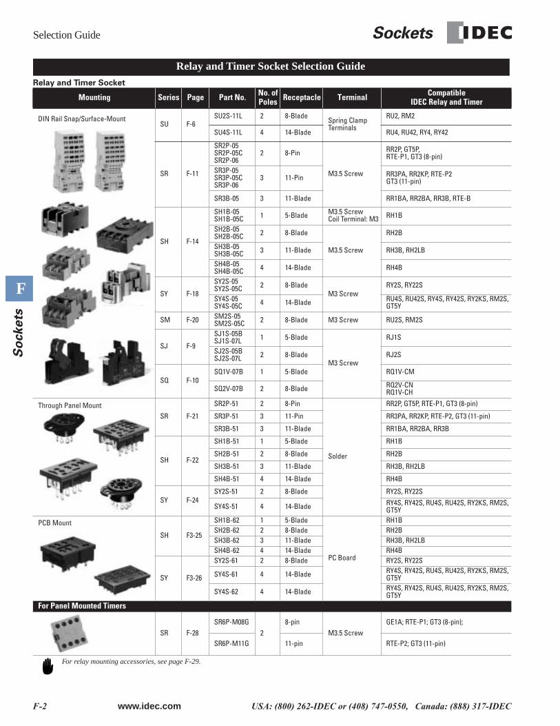
Relay and Timer Socket
Mounting Series Page Part No. No. ofPoles Receptacle Terminal Compatible
IDEC Relay and Timer
DIN Rail Snap/Surface-MountSU F-6
SU2S-11L 2 8-BladeSpring Clamp Terminals
RU2, RM2
SU4S-11L 4 14-Blade RU4, RU42, RY4, RY42
SR F-11
SR2P-05SR2P-05CSR2P-06
2 8-Pin
M3.5 Screw
RR2P, GT5P,RTE-P1, GT3 (8-pin)
SR3P-05SR3P-05CSR3P-06
3 11-Pin RR3PA, RR2KP, RTE-P2GT3 (11-pin)
SR3B-05 3 11-Blade RR1BA, RR2BA, RR3B, RTE-B
SH F-14
SH1B-05SH1B-05C 1 5-Blade M3.5 Screw
Coil Terminal: M3 RH1B
SH2B-05SH2B-05C 2 8-Blade
M3.5 Screw
RH2B
SH3B-05SH3B-05C 3 11-Blade RH3B, RH2LB
SH4B-05SH4B-05C 4 14-Blade RH4B
SY F-18
SY2S-05SY2S-05C 2 8-Blade
M3 ScrewRY2S, RY22S
SY4S-05SY4S-05C 4 14-Blade RU4S, RU42S, RY4S, RY42S, RY2KS, RM2S,
GT5Y
SM F-20 SM2S-05SM2S-05C 2 8-Blade M3 Screw RU2S, RM2S
SJ F-9
SJ1S-05BSJ1S-07L 1 5-Blade
M3 Screw
RJ1S
SJ2S-05BSJ2S-07L 2 8-Blade RJ2S
SQ F-10SQ1V-07B 1 5-Blade RQ1V-CM
SQ2V-07B 2 8-Blade RQ2V-CNRQ1V-CH
Through Panel MountSR F-21
SR2P-51 2 8-Pin
Solder
RR2P, GT5P, RTE-P1, GT3 (8-pin)
SR3P-51 3 11-Pin RR3PA, RR2KP, RTE-P2, GT3 (11-pin)
SR3B-51 3 11-Blade RR1BA, RR2BA, RR3B
SH F-22
SH1B-51 1 5-Blade RH1B
SH2B-51 2 8-Blade RH2B
SH3B-51 3 11-Blade RH3B, RH2LB
SH4B-51 4 14-Blade RH4B
SY F-24SY2S-51 2 8-Blade RY2S, RY22S
SY4S-51 4 14-Blade RY4S, RY42S, RU4S, RU42S, RY2KS, RM2S, GT5Y
PCB Mount
SH F3-25
SH1B-62 1 5-Blade
PC Board
RH1BSH2B-62 2 8-Blade RH2BSH3B-62 3 11-Blade RH3B, RH2LBSH4B-62 4 14-Blade RH4B
SY F3-26
SY2S-61 2 8-Blade RY2S, RY22S
SY4S-61 4 14-Blade RY4S, RY42S, RU4S, RU42S, RY2KS, RM2S, GT5Y
SY4S-62 4 14-Blade RY4S, RY42S, RU4S, RU42S, RY2KS, RM2S, GT5Y
For Panel Mounted Timers
SR F-28SR6P-M08G
28-pin
M3.5 ScrewGE1A; RTE-P1; GT3 (8-pin);
SR6P-M11G 11-pin RTE-P2; GT3 (11-pin)
Relay and Timer Socket Selection Guide
For relay mounting accessories, see page F-29.
Sockets
Selection Guide
www.idec.com
USA: (800) 262-IDEC or (408) 747-0550, Canada: (888) 317-IDEC F-3
F
So
ckets
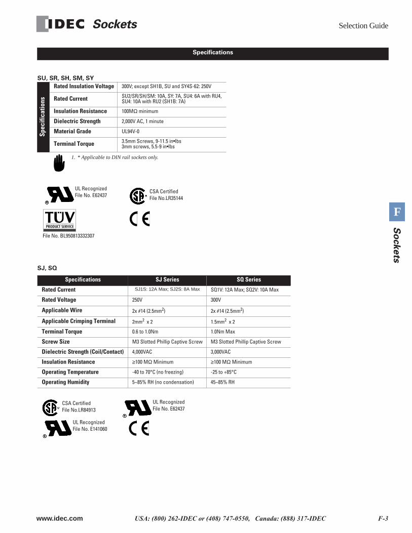
SU, SR, SH, SM, SY
SJ, SQ
Spec
ifica
tions
Rated Insulation Voltage
300V; except SH1B, SU and SY4S-62: 250V
Rated Current
SU2/SR/SH/SM: 10A, SY: 7A, SU4: 6A with RU4, SU4: 10A with RU2 (SH1B: 7A)
Insulation Resistance
100M
Ω
minimum
Dielectric Strength
2,000V AC, 1 minute
Material Grade
UL94V-0
Terminal Torque
3.5mm Screws, 9-11.5 in•lbs3mm screws, 5.5-9 in•lbs
Specifications SJ Series SQ Series
Rated Current
SJ1S: 12A Max; SJ2S: 8A Max
SQ1V: 12A Max; SQ2V: 10A Max
Rated Voltage
250V 300V
Applicable Wire
2x #14 (2.5mm
2
) 2x #14 (2.5mm
2
)
Applicable Crimping Terminal
2mm
2
x 2 1.5mm
2
x 2
Terminal Torque
0.6 to 1.0Nm 1.0Nm Max
Screw Size
M3 Slotted Phillip Captive Screw M3 Slotted Phillip Captive Screw
Dielectric Strength (Coil/Contact)
4,000VAC 3,000VAC
Insulation Resistance
≥
100 M
Ω
Minimum
≥
100 M
Ω
Minimum
Operating Temperature
-40 to 70°C (no freezing) -25 to +85°C
Operating Humidity
5~85% RH (no condensation) 45~85% RH
Specifications
1. * Applicable to DIN rail sockets only.
CSA CertifiedFile No.LR35144
UL RecognizedFile No. E62437
File No. BL950813332307
CSA CertifiedFile No.LR84913
UL RecognizedFile No. E141060
UL RecognizedFile No. E62437
Selection Guide
Sockets
F-4
www.idec.com
USA: (800) 262-IDEC or (408) 747-0550, Canada: (888) 317-IDEC
F
S
ockets
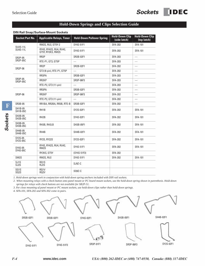
DIN Rail Snap/Surface-Mount Sockets
Socket Part No. Applicable Relays, Timer Hold-Down Pullover Spring Hold-Down Clip(side latch)
Hold-Down Clip(top latch)
SU2S-11LSU4S-11L
RM2S, RU2, GT5Y-2 SY4S-51F1 SFA-202 SFA-101
RY4S, RY42S, RU4, RU42, GT5Y, RY2KS, RM2S SY4S-51F1 SFA-202 SFA-101
SR2P-05SR2P-05C
RR2P SR2B-02F1 SFA-203 —
RTE-P1, GT3, GT5P — SFA-203 —
SR2P-06RR2P SR2B-02F1 SFA-202 —
GT3 (8-pin), RTE-P1, GT5P — SFA-202 —
SR3P-05SR3P-05C
RR3PA SR3B-02F1 SFA-203 —
RR2KP SR3P-06F3 SFA-203 —
RTE-P2, GT3 (11-pin) — SFA-203 —
SR3P-06
RR3PA SR3B-02F1 SFA-202 —
RR2KP SR3P-06F3 SFA-202 —
RTE-P2, GT3 (11-pin) — SFA-202 —
SR3B-05 RR1BA, RR2BA, RR3B, RTE-B SR3B-02F1 SFA-202 —
SH1B-05SH1B-05C RH1B SY2S-02F1 SFA-202 SFA-101
SH2B-05SH2B-05C RH2B SY4S-02F1 SFA-202 SFA-101
SH3B-05SH3B-05C RH3B, RH2LB SH3B-05F1 SFA-202 SFA-101
SH4B-05SH4B-05C RH4B SH4B-02F1 SFA-202 SFA-101
SY2S-05SY2S-05C RY2S, RY22S SY2S-02F1 SFA-202 SFA-101
SY4S-05SY4S-05C
RY4S, RY42S, RU4, RU42, RM2S SY4S-51F1 SFA-202 SFA-101
RY2KS, GT5Y (SY4S-51F3) SFA-202
SM2S RM2S, RU2 SY4S-51F1 SFA-202 SFA-101
SJ1SSJ2S
RQ1SRJ2S SJ9Z-C
SQ1SSQ2S
RQ1VRQ2V SQ9Z-C
1. Hold-down springs work in conjunction with hold-down spring anchors included with DIN rail sockets.2. When mounting relays with a check button onto panel mount or PC board mount sockets, use the hold-down spring shown in parenthesis. Hold-down
springs for relays with check buttons are not available for SR2P-51.3. For close mounting of panel mount or PC mount sockets, use hold-down clips rather than hold-down springs.4. SFA-101, SFA-202 and SFA-302 come in pairs.
SR2B-02F1 SR3B-02F1 SY4S-02F1 SH3B-05F1 SH4B-02F1
SY4S-51F1 SY4S-51F3 SR3P-01F1 SR3P-06F3 SY2S-02F1
Hold-Down Springs and Clips Selection Guide
Sockets
Selection Guide
www.idec.com
USA: (800) 262-IDEC or (408) 747-0550, Canada: (888) 317-IDEC F-5
F
So
ckets
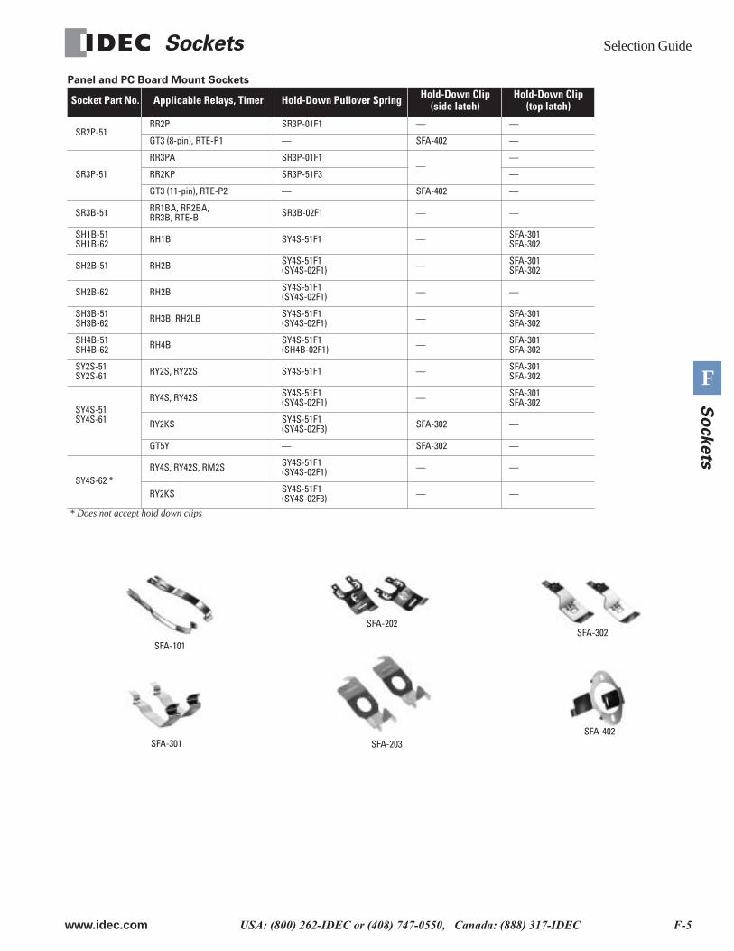
SFA-101
SFA-202SFA-302
SFA-402SFA-203SFA-301
Panel and PC Board Mount Sockets
* Does not accept hold down clips
Socket Part No. Applicable Relays, Timer Hold-Down Pullover Spring Hold-Down Clip(side latch)
Hold-Down Clip (top latch)
SR2P-51RR2P SR3P-01F1 — —
GT3 (8-pin), RTE-P1 — SFA-402 —
SR3P-51
RR3PA SR3P-01F1—
—
RR2KP SR3P-51F3 —
GT3 (11-pin), RTE-P2 — SFA-402 —
SR3B-51 RR1BA, RR2BA, RR3B, RTE-B SR3B-02F1 — —
SH1B-51SH1B-62 RH1B SY4S-51F1 — SFA-301
SFA-302
SH2B-51 RH2B SY4S-51F1(SY4S-02F1) — SFA-301
SFA-302
SH2B-62 RH2B SY4S-51F1(SY4S-02F1) — —
SH3B-51SH3B-62 RH3B, RH2LB SY4S-51F1
(SY4S-02F1) — SFA-301SFA-302
SH4B-51SH4B-62 RH4B SY4S-51F1
(SH4B-02F1) — SFA-301SFA-302
SY2S-51SY2S-61 RY2S, RY22S SY4S-51F1 — SFA-301
SFA-302
SY4S-51SY4S-61
RY4S, RY42S SY4S-51F1(SY4S-02F1) — SFA-301
SFA-302
RY2KS SY4S-51F1(SY4S-02F3) SFA-302 —
GT5Y — SFA-302 —
SY4S-62 *RY4S, RY42S, RM2S SY4S-51F1
(SY4S-02F1) — —
RY2KS SY4S-51F1(SY4S-02F3) — —
SU Series: DIN Rail Snap-Mount
Sockets
F-6
www.idec.com
USA: (800) 262-IDEC or (408) 747-0550, Canada: (888) 317-IDEC
F
S
ockets
Center of Relay-mounting area
Inside the Cable Ports
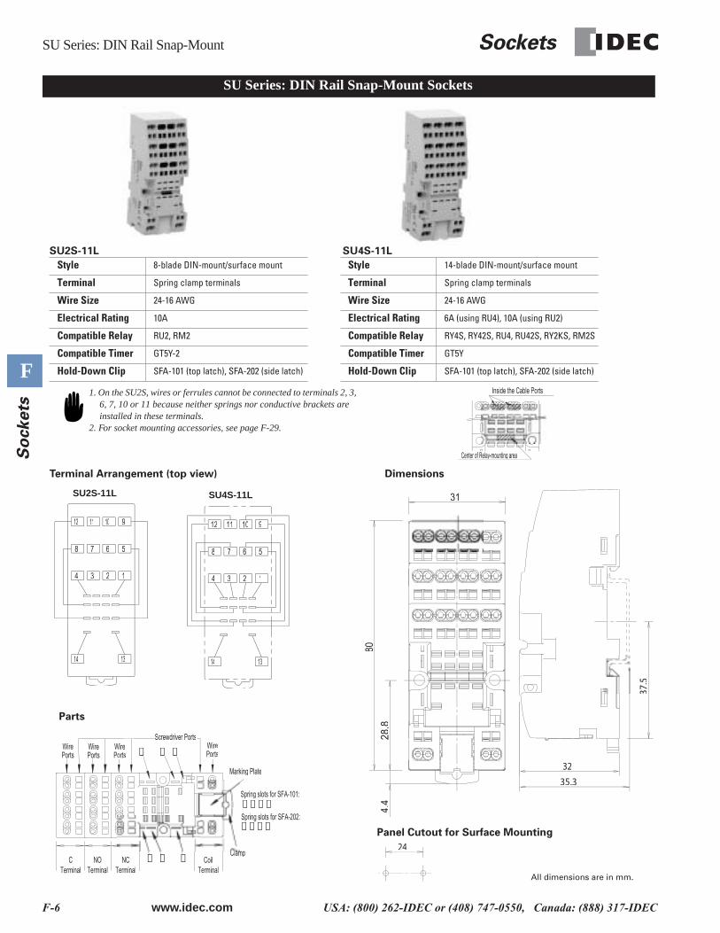
SU Series: DIN Rail Snap-Mount Sockets
28.8
80
31
4.4
32
37.5
35.3
24
Spring slots for SFA-202:
Spring slots for SFA-101:
Marking Plate
Clamp➀➀ ➁➁ ➂➂
➃ ➄ ➅
➀➁➄➅
➁➂➃➄
Screwdriver Ports
CTerminal
NOTerminal
NCTerminal
CoilTerminal
Wire Ports
Wire Ports
WirePorts
WirePorts
SU2S-11L SU4S-11L
Terminal Arrangement (top view) Dimensions
Style 8-blade DIN-mount/surface mount Style 14-blade DIN-mount/surface mount
Terminal Spring clamp terminals Terminal Spring clamp terminals
Wire Size 24-16 AWG Wire Size 24-16 AWG
Electrical Rating 10A Electrical Rating 6A (using RU4), 10A (using RU2)
Compatible Relay RU2, RM2 Compatible Relay RY4S, RY42S, RU4, RU42S, RY2KS, RM2S
Compatible Timer GT5Y-2 Compatible Timer GT5Y
Hold-Down Clip SFA-101 (top latch), SFA-202 (side latch) Hold-Down Clip SFA-101 (top latch), SFA-202 (side latch)
Inside the Cable Ports1. On the SU2S, wires or ferrules cannot be connected to terminals 2, 3, 6, 7, 10 or 11 because neither springs nor conductive brackets are installed in these terminals.
2. For socket mounting accessories, see page F-29.
SU2S-11L
14 13
1234
8 7 6 5
9101112 12 11 10 9
5678
4 3 2 1
1314
SU4S-11L
Panel Cutout for Surface Mounting
Parts
All dimensions are in mm.
Sockets
SU Series: DIN Rail Snap-Mount
www.idec.com
USA: (800) 262-IDEC or (408) 747-0550, Canada: (888) 317-IDEC F-7
F
So
ckets
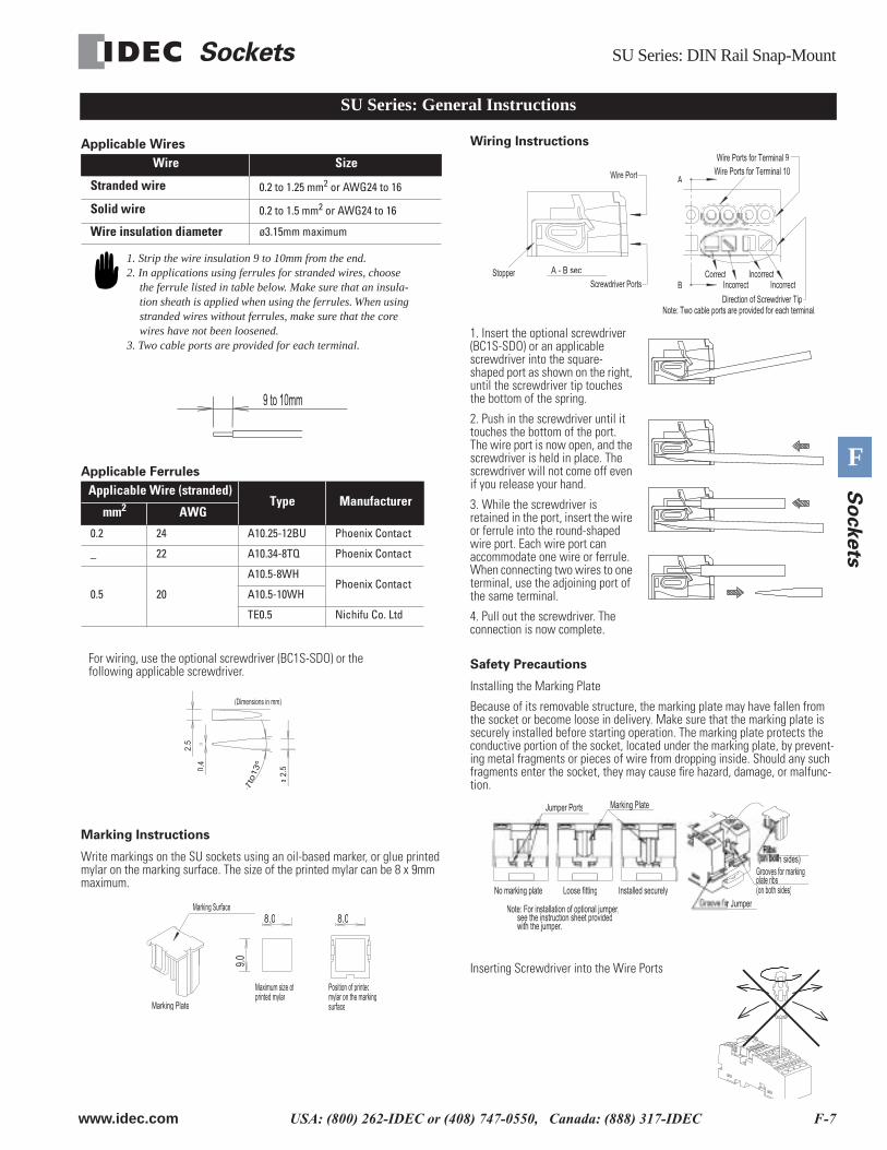
SU Series: General Instructions
Applicable Wires
Applicable Ferrules
Marking Instructions
Write markings on the SU sockets using an oil-based marker, or glue printed mylar on the marking surface. The size of the printed mylar can be 8 x 9mm maximum.
Wiring Instructions
1. Insert the optional screwdriver (BC1S-SDO) or an applicable screwdriver into the square-shaped port as shown on the right, until the screwdriver tip touches the bottom of the spring.
2. Push in the screwdriver until it touches the bottom of the port. The wire port is now open, and the screwdriver is held in place. The screwdriver will not come off even if you release your hand.
3. While the screwdriver is retained in the port, insert the wire or ferrule into the round-shaped wire port. Each wire port can accommodate one wire or ferrule. When connecting two wires to one terminal, use the adjoining port of the same terminal.
4. Pull out the screwdriver. The connection is now complete.
Safety Precautions
Installing the Marking Plate
Because of its removable structure, the marking plate may have fallen from the socket or become loose in delivery. Make sure that the marking plate is securely installed before starting operation. The marking plate protects the conductive portion of the socket, located under the marking plate, by prevent-ing metal fragments or pieces of wire from dropping inside. Should any such fragments enter the socket, they may cause fire hazard, damage, or malfunc-tion.
Inserting Screwdriver into the Wire Ports
Wire Size
Stranded wire 0.2 to 1.25 mm2 or AWG24 to 16
Solid wire 0.2 to 1.5 mm2 or AWG24 to 16
Wire insulation diameter ø3.15mm maximum
Applicable Wire (stranded)Type Manufacturer
mm2 AWG
0.2 24 A10.25-12BU Phoenix Contact
_ 22 A10.34-8TQ Phoenix Contact
0.5 20
A10.5-8WHPhoenix Contact
A10.5-10WH
TE0.5 Nichifu Co. Ltd
1. Strip the wire insulation 9 to 10mm from the end.2. In applications using ferrules for stranded wires, choose
the ferrule listed in table below. Make sure that an insula-tion sheath is applied when using the ferrules. When using stranded wires without ferrules, make sure that the core wires have not been loosened.
3. Two cable ports are provided for each terminal.
9 to 10mm
7to
13
7t
º
ø2.
50.4
2.5
(Dimensions in mm)
For wiring, use the optional screwdriver (BC1S-SDO) or the following applicable screwdriver.
8.0
9.0
8.0
Marking Plate
Position of printedmylar on the markingsurface
Maximum size ofprinted mylar
Marking Surface
Direction of Screwdriver Tip
Wire Ports for Terminal 9Wire Ports for Terminal 10
Stopper
Wire Port
Note: Two cable ports are provided for each terminal.
A
B
A - B secScrewdriver Ports
CorrectIncorrect
IncorrectIncorrect
(on both sides)
Marking Plate
Note: For installation of optional jumper, see the instruction sheet provided
p j pp j p
with the jumper.
plate ribs
r JumperInstalled securelyLoose fittingNo marking plate
Jumper Ports
SU Series: DIN Rail Snap-Mount
Sockets
F-8 www.idec.com USA: (800) 262-IDEC or (408) 747-0550, Canada: (888) 317-IDEC
F
So
ckets
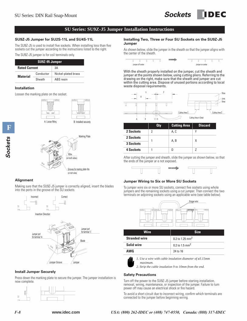
SU Series: SU9Z-J5 Jumper Installation Instructions
SU9Z-J5 Jumper for SU2S-11L and SU4S-11L
The SU9Z-J5 is used to install five sockets. When installing less than five sockets cut the jumper according to the instructions listed to the right.
The SU9Z-J5 jumper is for coil terminals only.
Installation
Loosen the marking plate on the socket.
Alignment
Making sure that the SU9Z-J5 jumper is correctly aligned, insert the blades into the ports in the groove of the SU sockets.
Install Jumper Securely
Press down the marking plate to secure the jumper. The jumper installation is now complete.
Installing Two, Three or Four SU Sockets on the SU9Z-J5 Jumper
As shown below, slide the jumper in the sheath so that the jumper aligns with the center of the sheath.
With the sheath properly installed on the jumper, cut the sheath and jumper at the points shown below, using cutting pliers. Referring to the drawing on the right, make sure that the sheath and jumper are cut within the cutting area. Dispose of unused portions according to local waste disposal requirements.
After cutting the jumper and sheath, slide the jumper as shown below, so that the ends of the jumper ar e not exposed.
Jumper Wiring to Six or More SU Sockets
To jumper wire six or more SU sockets, connect five sockets using whole jumpers and the remaining sockets using a cut jumper. Then connect the two terminals on adjoining sockets using an applicable wire (see table below).
Safety Precautions
Turn off the power to the SU9Z-J5 jumper before starting installation, removal, wiring, maintenance, or inspection of the jumper. Failure to turn power off may cause an electrical shock or fire hazard.
To avoid a short circuit due to incorrect wiring, confirm which terminals are connected to the jumper before beginning wiring.
SU9Z-95 Jumper
Rated Current 3A
MaterialConductor Nickel-plated brass
Sheath ABS resin
B: Installed securelyA: Loose fitting
Ribs
(on both sides)Grooves for marking plate ribs
CorrectIncorrect
Insertion Direction
Jumper Groove Jumper
Blade
Jumper portfor terminal 13
Jumper portfor terminal 14
Qty Cutting Area Discard
2 Sockets 2 A, C Y
2 Sockets1 A, B X
3 Sockets
4 Sockets 1 D Z
Wire Size
Stranded wire 0.2 to 1.25 mm2
Solid wire 0.2 to 1.5 mm2
AWG 24 to 16
Jumper on centerJumper off center
Cutting Area C
Cutting Area in Detail
Cutting Area D
SheaJump
SheaZ
X
Y
DCBA
Proper wire
1. Use a wire with cable insulation diameter of ø3.15mm maximum.
2. Strip the cable insulation 9 to 10mm from the end.
Sockets SJ Series: DIN Rail Snap-Mount
www.idec.com USA: (800) 262-IDEC or (408) 747-0550, Canada: (888) 317-IDEC F-9
F
So
ckets
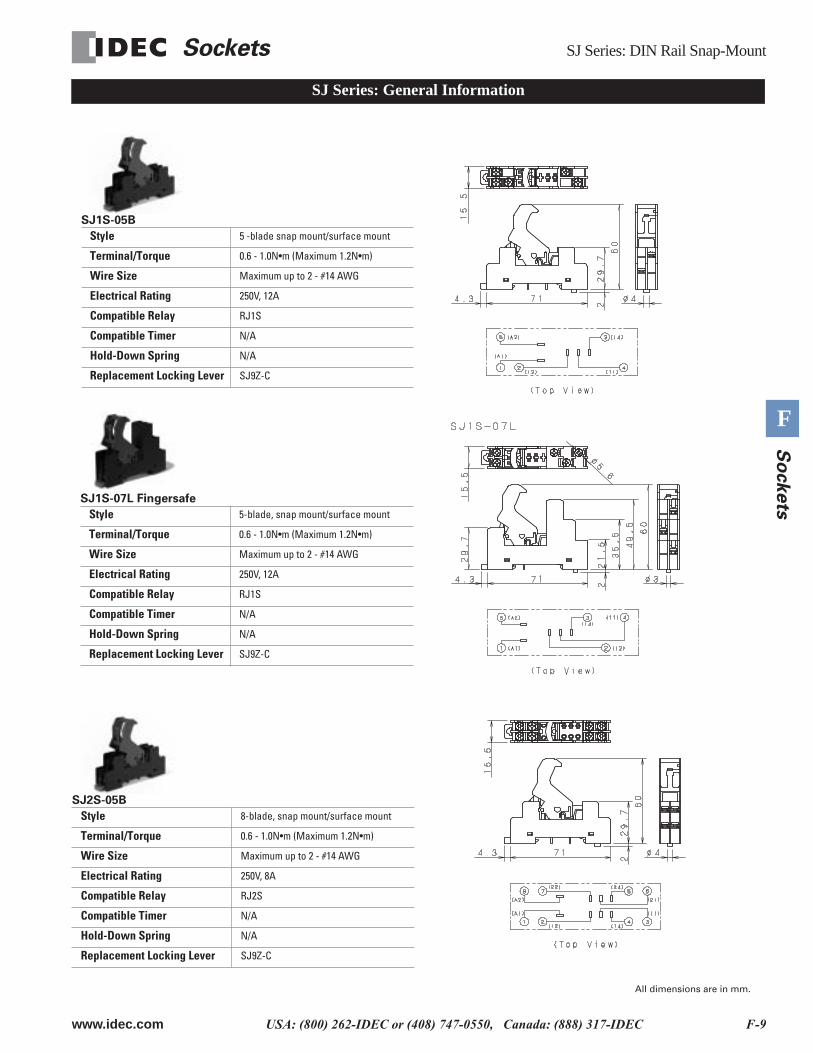
SJ Series: General Information
SJ1S-05B
Style 5 -blade snap mount/surface mount
Terminal/Torque 0.6 - 1.0N•m (Maximum 1.2N•m)
Wire Size Maximum up to 2 - #14 AWG
Electrical Rating 250V, 12A
Compatible Relay RJ1S
Compatible Timer N/A
Hold-Down Spring N/A
Replacement Locking Lever SJ9Z-C
SJ2S-05B
Style 8-blade, snap mount/surface mount
Terminal/Torque 0.6 - 1.0N•m (Maximum 1.2N•m)
Wire Size Maximum up to 2 - #14 AWG
Electrical Rating 250V, 8A
Compatible Relay RJ2S
Compatible Timer N/A
Hold-Down Spring N/A
Replacement Locking Lever SJ9Z-C
SJ1S-07L Fingersafe
Style 5-blade, snap mount/surface mount
Terminal/Torque 0.6 - 1.0N•m (Maximum 1.2N•m)
Wire Size Maximum up to 2 - #14 AWG
Electrical Rating 250V, 12A
Compatible Relay RJ1S
Compatible Timer N/A
Hold-Down Spring N/A
Replacement Locking Lever SJ9Z-C
All dimensions are in mm.
SJ/SQ Series: DIN Rail Snap-Mount Sockets
F-10 www.idec.com USA: (800) 262-IDEC or (408) 747-0550, Canada: (888) 317-IDEC
F
So
ckets
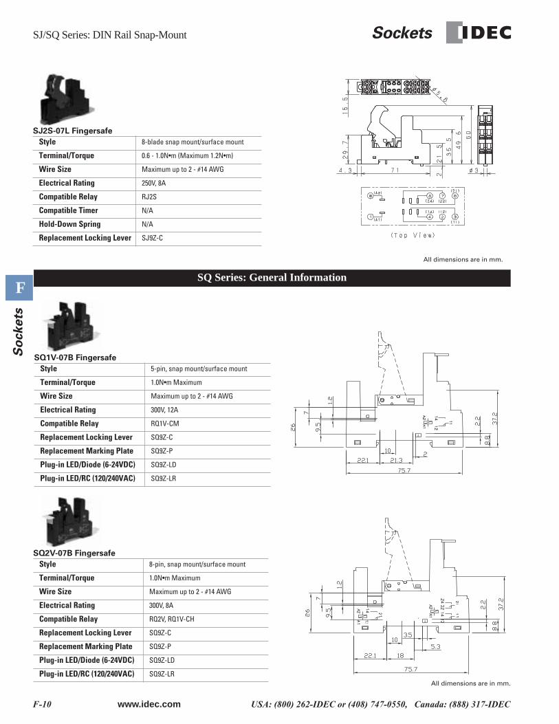
SQ Series: General Information
SJ2S-07L Fingersafe
Style 8-blade snap mount/surface mount
Terminal/Torque 0.6 - 1.0N•m (Maximum 1.2N•m)
Wire Size Maximum up to 2 - #14 AWG
Electrical Rating 250V, 8A
Compatible Relay RJ2S
Compatible Timer N/A
Hold-Down Spring N/A
Replacement Locking Lever SJ9Z-C
SQ1V-07B Fingersafe
Style 5-pin, snap mount/surface mount
Terminal/Torque 1.0N•m Maximum
Wire Size Maximum up to 2 - #14 AWG
Electrical Rating 300V, 12A
Compatible Relay RQ1V-CM
Replacement Locking Lever SQ9Z-C
Replacement Marking Plate SQ9Z-P
Plug-in LED/Diode (6-24VDC) SQ9Z-LD
Plug-in LED/RC (120/240VAC) SQ9Z-LR
SQ2V-07B Fingersafe
Style 8-pin, snap mount/surface mount
Terminal/Torque 1.0N•m Maximum
Wire Size Maximum up to 2 - #14 AWG
Electrical Rating 300V, 8A
Compatible Relay RQ2V, RQ1V-CH
Replacement Locking Lever SQ9Z-C
Replacement Marking Plate SQ9Z-P
Plug-in LED/Diode (6-24VDC) SQ9Z-LD
Plug-in LED/RC (120/240VAC) SQ9Z-LR
All dimensions are in mm.
All dimensions are in mm.
Sockets SR Series: DIN Rail Snap-Mount
www.idec.com USA: (800) 262-IDEC or (408) 747-0550, Canada: (888) 317-IDEC F-11
F
So
ckets
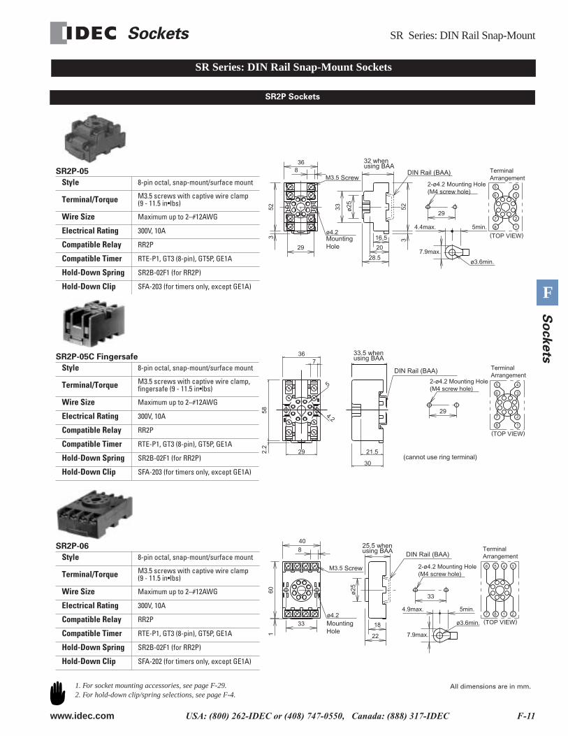
SR Series: DIN Rail Snap-Mount Sockets
SR2P Sockets
2-ø4.2 Mounting Hole(M4 screw hole)
7.9max.
ø3.6min.
M3.5
ø4.2
TerminalArrangement
(TOP VIEW)
6
5 4
3
7
8
2
1
16.5
20
28.5
33 523
ø25
29
4.4max. 5min.
8
523
36
29
Mounting Hole
Screw
32 when using BAA
DIN Rail (BAA)SR2P-05
Style 8-pin octal, snap-mount/surface mount
Terminal/Torque M3.5 screws with captive wire clamp(9 - 11.5 in•lbs)
Wire Size Maximum up to 2–#12AWG
Electrical Rating 300V, 10A
Compatible Relay RR2P
Compatible Timer RTE-P1, GT3 (8-pin), GT5P, GE1A
Hold-Down Spring SR2B-02F1 (for RR2P)
Hold-Down Clip SFA-203 (for timers only, except GE1A)
8
7
6
5 4
3
2
1
5
21.5
4.2
2.2
58
30
29
736
(TOP VIEW)
6
5 4
3
7
8
2
1
29
TerminalArrangement
DIN Rail (BAA)
2-ø4.2 Mounting Hole(M4 screw hole)
33.5 when using BAA
(cannot use ring terminal)
SR2P-05C Fingersafe
Style 8-pin octal, snap-mount/surface mount
Terminal/Torque M3.5 screws with captive wire clamp, fingersafe (9 - 11.5 in•lbs)
Wire Size Maximum up to 2–#12AWG
Electrical Rating 300V, 10A
Compatible Relay RR2P
Compatible Timer RTE-P1, GT3 (8-pin), GT5P, GE1A
Hold-Down Spring SR2B-02F1 (for RR2P)
Hold-Down Clip SFA-203 (for timers only, except GE1A)
ø3.6min.
7.9max.
ø4.2(TOP VIEW)
6 5 4 3
2187
8
40
160
33 18
22
33
4.9max. 5min.
ø25
M3.5 Screw
Mounting Hole
25.5 when using BAA DIN Rail (BAA)
2-ø4.2 Mounting Hole(M4 screw hole)
TerminalArrangement
SR2P-06
Style 8-pin octal, snap-mount/surface mount
Terminal/Torque M3.5 screws with captive wire clamp(9 - 11.5 in•lbs)
Wire Size Maximum up to 2–#12AWG
Electrical Rating 300V, 10A
Compatible Relay RR2P
Compatible Timer RTE-P1, GT3 (8-pin), GT5P, GE1A
Hold-Down Spring SR2B-02F1 (for RR2P)
Hold-Down Clip SFA-202 (for timers only, except GE1A)
1. For socket mounting accessories, see page F-29.2. For hold-down clip/spring selections, see page F-4.
All dimensions are in mm.
SR Series: DIN Rail Snap-Mount Sockets
F-12 www.idec.com USA: (800) 262-IDEC or (408) 747-0550, Canada: (888) 317-IDEC
F
So
ckets
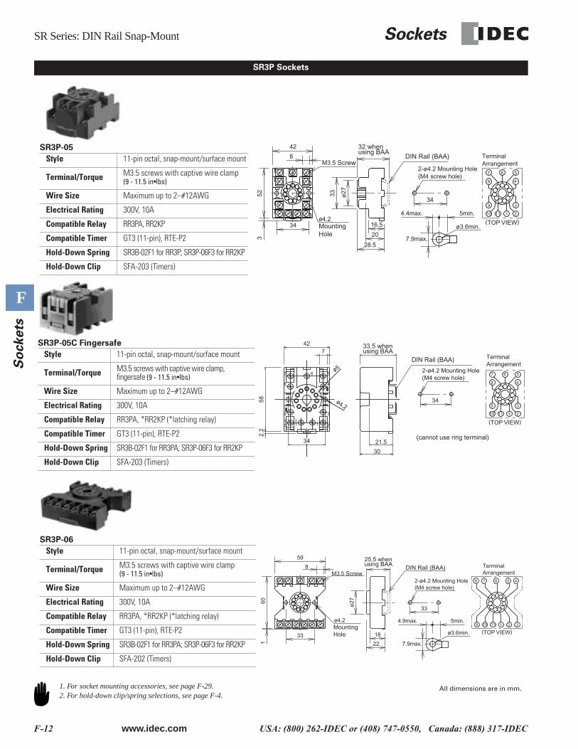
SR3P Sockets
ø3.6min.
7.9max.
ø4.2 (TOP VIEW)
8
7 6 5
4
9
1110 1 2
334
4.4max. 5min.
16.5
20
28.5
ø2733
8
42
34
523
M3.5 Screw
32 when using BAA
DIN Rail (BAA) TerminalArrangement
2-ø4.2 Mounting Hole(M4 screw hole)
Mounting Hole
SR3P-05
Style 11-pin octal, snap-mount/surface mount
Terminal/Torque M3.5 screws with captive wire clamp(9 - 11.5 in•lbs)
Wire Size Maximum up to 2–#12AWG
Electrical Rating 300V, 10A
Compatible Relay RR3PA, RR2KP
Compatible Timer GT3 (11-pin), RTE-P2
Hold-Down Spring SR3B-02F1 for RR3P; SR3P-06F3 for RR2KP
Hold-Down Clip SFA-203 (Timers)
4
3
211
01
1
8
7 6 5
9
ø5
30
34 21.5
427
ø4.2
2.2
58
(TOP VIEW)
8
7 6 5
4
9
1110 1 2
334
33.5 when using BAA
DIN Rail (BAA)
2-ø4.2 Mounting Hole(M4 screw hole)
TerminalArrangement
(cannot use ring terminal)
SR3P-05C Fingersafe
Style 11-pin octal, snap-mount/surface mount
Terminal/Torque M3.5 screws with captive wire clamp, fingersafe (9 - 11.5 in•lbs)
Wire Size Maximum up to 2–#12AWG
Electrical Rating 300V, 10A
Compatible Relay RR3PA, *RR2KP (*latching relay)
Compatible Timer GT3 (11-pin), RTE-P2
Hold-Down Spring SR3B-02F1 for RR3PA; SR3P-06F3 for RR2KP
Hold-Down Clip SFA-203 (Timers)
2-ø4.2 Mounting Hole(M4 screw hole)
M3.5TerminalArrangement
Mounting Hole
Screw
25.5 when using BAA
DIN Rail (BAA)
ø3.6min.
7.9max.
ø4.2
(TOP VIEW)
8 7 6 5 4
9 1110 1 2 3
33
4.9max. 5min.
8
59
33
601 22
18
ø27
SR3P-06
Style 11-pin octal, snap-mount/surface mount
Terminal/Torque M3.5 screws with captive wire clamp(9 - 11.5 in•lbs)
Wire Size Maximum up to 2–#12AWG
Electrical Rating 300V, 10A
Compatible Relay RR3PA, *RR2KP (*latching relay)
Compatible Timer GT3 (11-pin), RTE-P2
Hold-Down Spring SR3B-02F1 for RR3PA; SR3P-06F3 for RR2KP
Hold-Down Clip SFA-202 (Timers)
1. For socket mounting accessories, see page F-29.2. For hold-down clip/spring selections, see page F-4.
All dimensions are in mm.
Sockets SR Series: DIN Rail Snap-Mount
www.idec.com USA: (800) 262-IDEC or (408) 747-0550, Canada: (888) 317-IDEC F-13
F
So
ckets
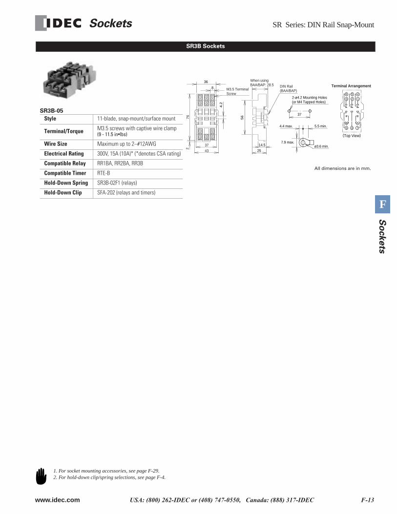
SR3B Sockets
SR3B-05
Style 11-blade, snap-mount/surface mount
Terminal/Torque M3.5 screws with captive wire clamp(9 - 11.5 in•lbs)
Wire Size Maximum up to 2–#12AWG
Electrical Rating 300V, 15A (10A)* (*denotes CSA rating)
Compatible Relay RR1BA, RR2BA, RR3B
Compatible Timer RTE-B
Hold-Down Spring SR3B-02F1 (relays)
Hold-Down Clip SFA-202 (relays and timers)7
6
37
43
2
25
14.5
56
When using BAA/BAP: 28.5 DIN Rail
(BAA/BAP)
37
ø3.6 min.7.9 max.
4.4 max. 5.5 min.
4
1
9
B
8
A
6
3
5
2
7
Terminal Arrangement
2-ø4.2 Mounting Holes(or M4 Tapped Holes)
36
8 M3.5 TerminalScrew
4.2
(Top View)
All dimensions are in mm.
1. For socket mounting accessories, see page F-29.2. For hold-down clip/spring selections, see page F-4.
SH Series: DIN Rail Snap-Mount Sockets
F-14 www.idec.com USA: (800) 262-IDEC or (408) 747-0550, Canada: (888) 317-IDEC
F
So
ckets
SH Series: DIN Rail Snap-Mount Sockets
SH1B Sockets
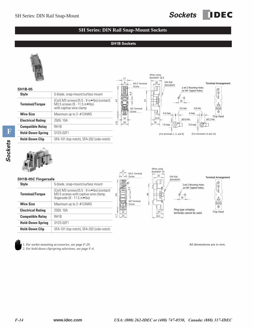
SH1B-05
Style 5-blade, snap-mount/surface mount
Terminal/Torque(Coil) M3 screws/(5.5 - 9 in•lbs) (contact) M3.5 screws (9 - 11.5 in•lbs)with captive wire clamp
Wire Size Maximum up to 2–#12AWG
Electrical Rating 250V, 10A
Compatible Relay RH1B
Hold-Down Spring SY2S-02F1
Hold-Down Clip SFA-101 (top notch), SFA-202 (side notch)
5
1
9
14 13
Terminal Arrangement
17
4.2
67
2.5 20
16
8
7.9 max.25
47
18
14.5
4.4 max.
5.5 min.M3 TerminalScrew
M3.5 TerminalScrew
When usingBAA/BAP: 28.5
DIN Rail(BAA/BAP)
(For terminals 1, 5, and 9)
ø3.6 min.
16
2-ø4.2 Mounting Holes(or M4 Tapped Holes)
5.9 max.
4 max.
4.8 min.
(For terminals 13 and 14)
ø3.2 min.(Top View)
SH1B-05C Fingersafe
Style 5-blade, snap-mount/surface mount
Terminal/Torque(Coil) M3 screws/(5.5 - 9 in•lbs) (contact) M3.5 screws with captive wire clamp, fingersafe (9 - 11.5 in•lbs)
Wire Size Maximum up to 2–#12AWG
Electrical Rating 250V, 10A
Compatible Relay RH1B
Hold-Down Spring SY2S-02F1
Hold-Down Clip SFA-101 (top notch), SFA-202 (side notch)
ø5
16
25
1.7 29.5
18.7
48
17
7
69
20
4.2
16
M3.5 Terminal Screw
M3 TerminalScrew
When using BAA/BAP: 33
2-ø4.2 Mounting Holes(or M4 Tapped Holes)
5
1
9
14 13
Terminal ArrangementDIN Rail(BAA/BAP)
Ring type crimping terminals cannot be used. (Top View)
1. For socket mounting accessories, see page F-29.2. For hold-down clip/spring selections, see page F-4.
All dimensions are in mm.
Sockets SH Series: DIN Rail Snap-Mount
www.idec.com USA: (800) 262-IDEC or (408) 747-0550, Canada: (888) 317-IDEC F-15
F
So
ckets
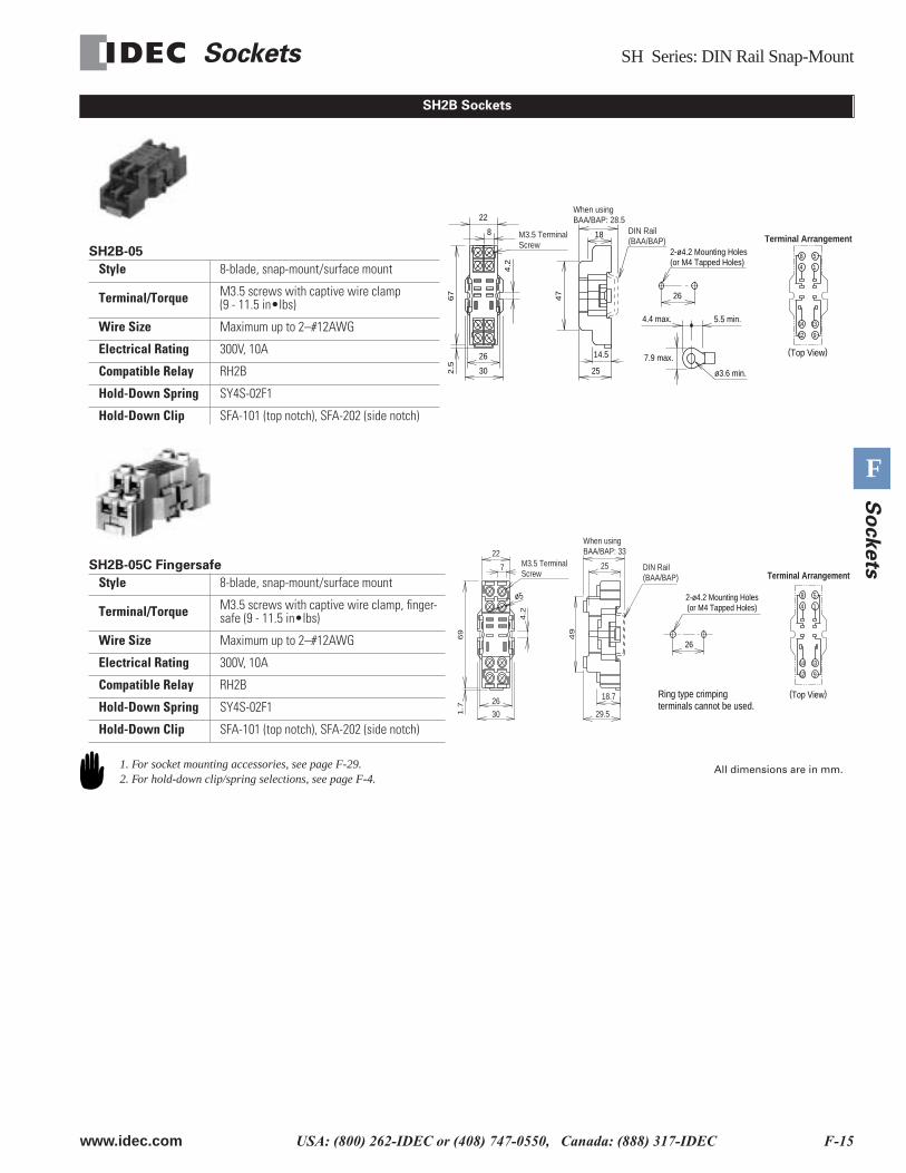
SH2B Sockets
SH2B-05
Style 8-blade, snap-mount/surface mount
Terminal/Torque M3.5 screws with captive wire clamp(9 - 11.5 in•lbs)
Wire Size Maximum up to 2–#12AWG
Electrical Rating 300V, 10A
Compatible Relay RH2B
Hold-Down Spring SY4S-02F1
Hold-Down Clip SFA-101 (top notch), SFA-202 (side notch)
22
4.2
67
2.5
8
26
25
47
18
14.526
30
M3.5 TerminalScrew
When usingBAA/BAP: 28.5
DIN Rail(BAA/BAP)
8
4
5
1
12
14
9
13
Terminal Arrangement2-ø4.2 Mounting Holes(or M4 Tapped Holes)
7.9 max.
4.4 max. 5.5 min.
ø3.6 min.
(Top View)
SH2B-05C Fingersafe
Style 8-blade, snap-mount/surface mount
Terminal/Torque M3.5 screws with captive wire clamp, finger-safe (9 - 11.5 in•lbs)
Wire Size Maximum up to 2–#12AWG
Electrical Rating 300V, 10A
Compatible Relay RH2B
Hold-Down Spring SY4S-02F1
Hold-Down Clip SFA-101 (top notch), SFA-202 (side notch)
ø5
1.7
69
4.2
22
7
30
26
M3.5 TerminalScrew
8
4
5
1
12
14
9
13
Terminal Arrangement25
29.5
18.7
49
DIN Rail (BAA/BAP)
When usingBAA/BAP: 33
26
2-ø4.2 Mounting Holes(or M4 Tapped Holes)
Ring type crimping terminals cannot be used.
(Top View)
1. For socket mounting accessories, see page F-29.2. For hold-down clip/spring selections, see page F-4.
All dimensions are in mm.
SH Series: DIN Rail Snap-Mount Sockets
F-16 www.idec.com USA: (800) 262-IDEC or (408) 747-0550, Canada: (888) 317-IDEC
F
So
ckets
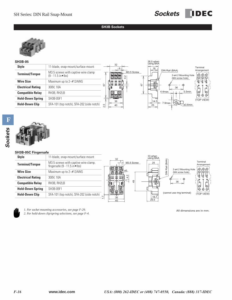
SH3B Sockets
(TOP VIEW)
M3.5 Screw
ø3.6min.7.9max.
5
1
12
14
10
13
8
4
6
2
9
36
25
32
4.2
672.
5
47
18
14.5
8
4.4max. 5.5min.
36
40
2-ø4.2 Mounting Hole(M4 screw hole)
TerminalArrangement
28.5 when using BAA
DIN Rail (BAA)
SH3B-05
Style 11-blade, snap-mount/surface mount
Terminal/Torque M3.5 screws with captive wire clamp(9 - 11.5 in•lbs)
Wire Size Maximum up to 2–#12AWG
Electrical Rating 300V, 10A
Compatible Relay RH3B, RH2LB
Hold-Down Spring SH3B-05F1
Hold-Down Clip SFA-101 (top notch), SFA-202 (side notch)
14
5
1
12
12
41
910
14 13
1121
A2 A1
2242
44 24
4 2
8 6
M3.5 Screw 25
1.7
29.518.7
32
49
4.2
7
4036
ø5
(TOP VIEW)
5
1
12
14
10
13
8
4
6
2
9
36
(cannot use ring terminal)
2-ø4.2 Mounting Hole(M4 screw hole)
TerminalArrangement
33 when using BAA
DIN
Rai
l (B
AA
)
SH3B-05C Fingersafe
Style 11-blade, snap-mount/surface mount
Terminal/Torque M3.5 screws with captive wire clamp, fingersafe (9 - 11.5 in•lbs)
Wire Size Maximum up to 2–#12AWG
Electrical Rating 300V, 10A
Compatible Relay RH3B, RH2LB
Hold-Down Spring SH3B-05F1
Hold-Down Clip SFA-101 (top notch), SFA-202 (side notch)
1. For socket mounting accessories, see page F-29.2. For hold-down clip/spring selections, see page F-4.
All dimensions are in mm.
Sockets SH Series: DIN Rail Snap-Mount
www.idec.com USA: (800) 262-IDEC or (408) 747-0550, Canada: (888) 317-IDEC F-17
F
So
ckets
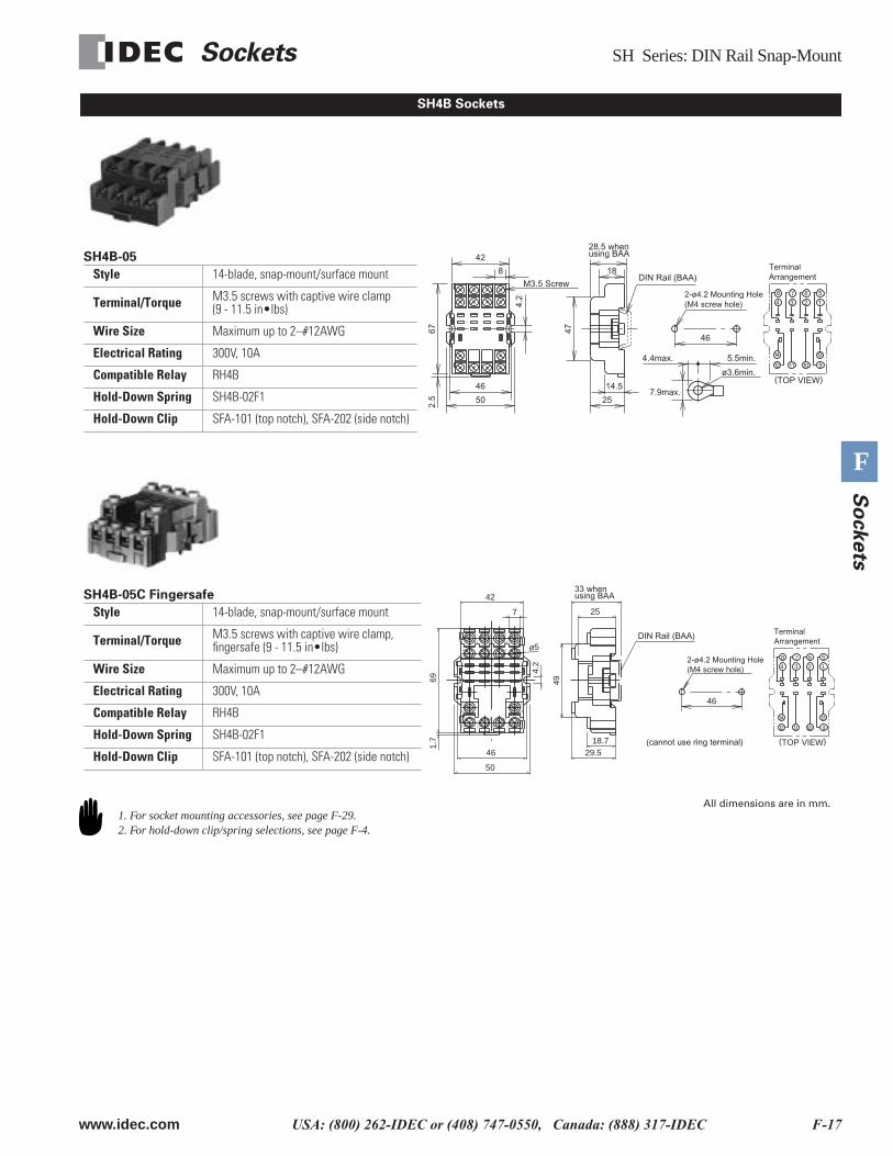
SH4B Sockets
(TOP VIEW)
M3.5 Screw
ø3.6min.
7.9max.
5
1
9
13
10
14
8
4
7
3
6
2
12 11
46
25
42
4.2
672.
5
47
18
14.5
8
4.4max. 5.5min.
46
50
2-ø4.2 Mounting Hole(M4 screw hole)
TerminalArrangement
28.5 when using BAA
DIN Rail (BAA)
SH4B-05
Style 14-blade, snap-mount/surface mount
Terminal/Torque M3.5 screws with captive wire clamp(9 - 11.5 in•lbs)
Wire Size Maximum up to 2–#12AWG
Electrical Rating 300V, 10A
Compatible Relay RH4B
Hold-Down Spring SH4B-02F1
Hold-Down Clip SFA-101 (top notch), SFA-202 (side notch)
4 3 2 1
8 67 5
32
31
22
41
A2 A1
12
142434
12 11 10 9
14
44
21 11
42
13
ø5
25
4.2
1.7
69
46
42
7
18.729.5
50
49
(TOP VIEW)
5
1
9
13
10
14
8
4
7
3
6
2
12 11
46
(cannot use ring terminal)
2-ø4.2 Mounting Hole(M4 screw hole)
TerminalArrangement
33 when using BAA
DIN Rail (BAA)
SH4B-05C Fingersafe
Style 14-blade, snap-mount/surface mount
Terminal/Torque M3.5 screws with captive wire clamp, fingersafe (9 - 11.5 in•lbs)
Wire Size Maximum up to 2–#12AWG
Electrical Rating 300V, 10A
Compatible Relay RH4B
Hold-Down Spring SH4B-02F1
Hold-Down Clip SFA-101 (top notch), SFA-202 (side notch)
1. For socket mounting accessories, see page F-29.2. For hold-down clip/spring selections, see page F-4.
All dimensions are in mm.
SY Series: DIN Rail Snap-Mount Sockets
F-18 www.idec.com USA: (800) 262-IDEC or (408) 747-0550, Canada: (888) 317-IDEC
F
So
ckets
SY Series: DIN Rail Snap-Mount Sockets
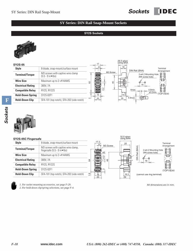
SY2S Sockets
M3 Screw
5.9max.
ø3.2min.(TOP VIEW)
8
4
5
1
12
14
9
13
16
25
4max. 4.8min.
6
17
4.2
622
45
18
20
16 14.5
28.5 when using BAA
DIN Rail (BAA)
2-ø4.2 Mounting Hole(M4 screw hole)
TerminalArrangement
SY2S-05
Style 8-blade, snap-mount/surface mount
Terminal/Torque M3 screws with captive wire clamp(5.5 - 9 in•lbs)
Wire Size Maximum up to 2–#14AWG
Electrical Rating 300V, 7A
Compatible Relay RY2S, RY22S
Hold-Down Spring SY2S-02F1
Hold-Down Clip SFA-101 (top notch), SFA-202 (side notch)
12
1
5
14
8
14
A2
44
9
11
12
41
13
42
A1
4
M3 Screw
ø5
25
46
2918.2
4.2
1.6
64
617.2
1620
2
(TOP VIEW)
8
4
5
1
12
14
9
13
16
2-ø4.2 Mounting Hole(M4 screw hole)
TerminalArrangement
32.5 when using BAA
DIN
Rai
l (B
AA
)
(cannot use ring terminal)
SY2S-05C Fingersafe
Style 8-blade, snap-mount/surface mount
Terminal/Torque M3 screws with captive wire clamp, fingersafe (5.5 - 9 in•lbs)
Wire Size Maximum up to 2–#14AWG
Electrical Rating 300V, 7A
Compatible Relay RY2S, RY22S
Hold-Down Spring SY2S-02F1
Hold-Down Clip SFA-101 (top notch), SFA-202 (side notch)
1. For socket mounting accessories, see page F-29.2. For hold-down clip/spring selections, see page F-4.
All dimensions are in mm.
Sockets SY Series: DIN Rail Snap-Mount
www.idec.com USA: (800) 262-IDEC or (408) 747-0550, Canada: (888) 317-IDEC F-19
F
So
ckets
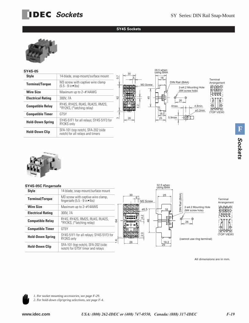
SY4S Sockets
M3 Screw
5.9max.
ø3.2min.(TOP VIEW)
1
13
9
14
12 11 10
5678
4 3 2
26
18.5
25
4max. 4.8min.
6
30
26
4.2
623
0.7
45
18
2-ø4.2 Mounting Hole(M4 screw hole)
TerminalArrangement
28.5 whenusing BAA
DIN Rail (BAA)
SY4S-05
Style 14-blade, snap-mount/surface mount
Terminal/Torque M3 screw with captive wire clamp(5.5 - 9 in•lbs)
Wire Size Maximum up to 2–#14AWG
Electrical Rating 300V, 7A
Compatible Relay RY4S, RY42S, RU4S, RU42S, RM2S, *RY2KS, (*latching relay)
Compatible Timer GT5Y
Hold-Down Spring SY4S-51F1 for all relays; SY4S-51F3 for RY2KS only
Hold-Down Clip SFA-101 (top notch), SFA-202 (side notch) for all relays and timers
9
11
12
13
A1
10
21
5
12
1
14
42
4
8
44
A2
23
14
31
6
11
24
32
34
41
22
7
M3 Screw
ø5.5 18
25
2.0
306
64
26
46
1.6
4.2
2918.2
(TOP VIEW)
1
13
9
14
12 11 10
5678
4 3 2
26
(cannot use ring terminal)
2-ø4.2 Mounting Hole(M4 screw hole)
TerminalArrangement
32.5 when using BAA
DIN
Rai
l (B
AA
)
SY4S-05C Fingersafe
Style 14-blade, snap-mount/surface mount
Terminal/Torque M3 screw with captive wire clamp, fingersafe (5.5 - 9 in•lbs)
Wire Size Maximum up to 2–#14AWG
Electrical Rating 300V, 7A
Compatible Relay RY4S, RY42S, RM2S, RU4S, RU42S, *RY2KS, (*latching relay)
Compatible Timer GT5Y
Hold-Down Spring SY4S-51F1 for all relays; SY4S-51F3 for RY2KS only
Hold-Down Clip SFA-101 (top notch), SFA-202 (side notch) for GT5Y timer and relays
All dimensions are in mm.
1. For socket mounting accessories, see page F-29.2. For hold-down clip/spring selections, see page F-4.
SM Series: DIN Rail Snap-Mount Sockets
F-20 www.idec.com USA: (800) 262-IDEC or (408) 747-0550, Canada: (888) 317-IDEC
F
So
ckets
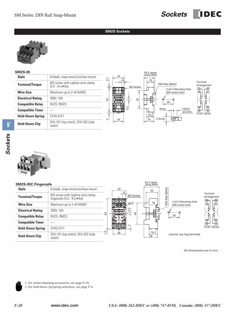
SM2S Sockets
M3 Screw
5.9max.
ø3.2min.
14
13
9
14
12
58
26
18.5
25
4max. 4.8min.
45
186
30
26
4.2
623
0.7
(TOP VIEW)
2-ø4.2 Mounting Hole(M4 screw hole)
TerminalArrangement
28.5 when using BAA
DIN Rail (BAA)
SM2S-05
Style 8-blade, snap-mount/surface mount
Terminal/Torque M3 screw with captive wire clamp(5.5 - 9 in•lbs)
Wire Size Maximum up to 2–#14AWG
Electrical Rating 300V, 10A
Compatible Relay RU2S, RM2S
Compatible Timer —
Hold-Down Spring SY4S-51F1
Hold-Down Clip SFA-101 (top notch), SFA-202 (side notch)
9
11
12
13
A1
10
21
5
12
1
14
42
4
8
44
A2
23
14
31
6
11
24
32
34
41
22
7
M3 Screw
ø5.5
25
18
2
306
64
26
46
1.6
4.2
2918.2
26
14
13
9
14
12
58
(TOP VIEW)
(cannot use ring terminal)
2-ø4.2 Mounting Hole(M4 screw hole)
TerminalArrangement
32.5 when using BAA
DIN
Rai
l (B
AA
)
SM2S-05C Fingersafe
Style 8-blade, snap-mount/surface mount
Terminal/Torque M3 screw with captive wire clamp, fingersafe (5.5 - 9 in•lbs)
Wire Size Maximum up to 2–#14AWG
Electrical Rating 300V, 10A
Compatible Relay RU2S, RM2S
Compatible Timer —
Hold-Down Spring SY4S-51F1
Hold-Down Clip SFA-101 (top notch), SFA-202 (side notch)
All dimensions are in mm.
1. For socket mounting accessories, see page F-29.2. For hold-down clip/spring selections, see page F-4.
Sockets SR Series: Panel Mount
www.idec.com USA: (800) 262-IDEC or (408) 747-0550, Canada: (888) 317-IDEC F-21
F
So
ckets
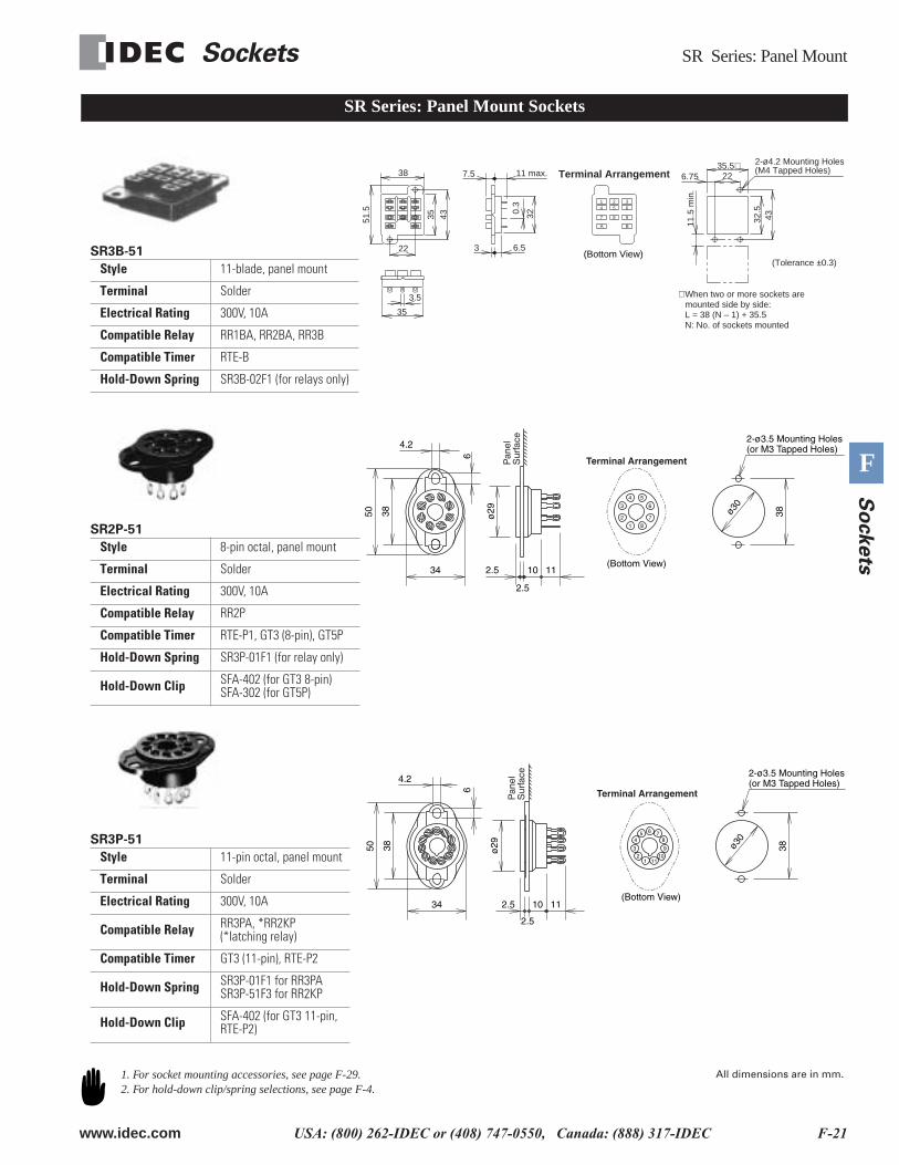
SR Series: Panel Mount Sockets
SR3B-51
Style 11-blade, panel mount
Terminal Solder
Electrical Rating 300V, 10A
Compatible Relay RR1BA, RR2BA, RR3B
Compatible Timer RTE-B
Hold-Down Spring SR3B-02F1 (for relays only)
35
3.5
7.5 11 max.
A B
7 8 9
1 2 34 5 6
38
51.5
22
35 43
0.3
32
6.53
35.5∗6.75
32.5
43
11.5
min
.
22
2-ø4.2 Mounting Holes(M4 Tapped Holes)
(Tolerance ±0.3)
∗ When two or more sockets are mounted side by side:L = 38 (N – 1) + 35.5N: No. of sockets mounted
(Bottom View)
Terminal Arrangement
SR2P-51
Style 8-pin octal, panel mount
Terminal Solder
Electrical Rating 300V, 10A
Compatible Relay RR2P
Compatible Timer RTE-P1, GT3 (8-pin), GT5P
Hold-Down Spring SR3P-01F1 (for relay only)
Hold-Down Clip SFA-402 (for GT3 8-pin)SFA-302 (for GT5P)
2.5
6
3850
4.2
34 2.5 10 11
2-ø3.5 Mounting Holes(or M3 Tapped Holes)
ø30
38ø29
Pan
elS
urfa
ce1
2
3
4 5
6
7
8
(Bottom View)
Terminal Arrangement
SR3P-51
Style 11-pin octal, panel mount
Terminal Solder
Electrical Rating 300V, 10A
Compatible Relay RR3PA, *RR2KP (*latching relay)
Compatible Timer GT3 (11-pin), RTE-P2
Hold-Down Spring SR3P-01F1 for RR3PA SR3P-51F3 for RR2KP
Hold-Down Clip SFA-402 (for GT3 11-pin, RTE-P2)
2.5
6
3850
4.2
34 2.5 10 11
ø29 ø3
0
382-ø3.5 Mounting Holes(or M3 Tapped Holes)
Pan
elS
urfa
ce
10111
23
45 6 7
8
9
(Bottom View)
Terminal Arrangement
1. For socket mounting accessories, see page F-29.2. For hold-down clip/spring selections, see page F-4.
All dimensions are in mm.
SH Series: Panel Mount Sockets
F-22 www.idec.com USA: (800) 262-IDEC or (408) 747-0550, Canada: (888) 317-IDEC
F
So
ckets
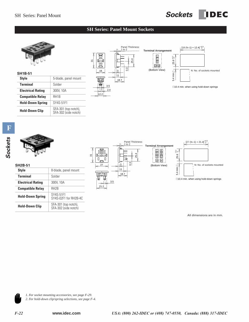
SH Series: Panel Mount Sockets
SH1B-51
Style 5-blade, panel mount
Terminal Solder
Electrical Rating 300V, 10A
Compatible Relay RH1B
Hold-Down Spring SY4S-51F1
Hold-Down Clip SFA-301 (top notch), SFA-302 (side notch)
3
11
18.7
18
312.4
12.2
0.3
25.4
3.5
Panel Thickness:1 to 2
13
159
(Bottom View)
14
Terminal Arrangement
25.6
0+0.5
+0.
20
∗ 10.4 min. when using hold-down springs
5.4
min
.∗
N: No. of sockets mounted
[18 (N–1) + 12.4]
SH2B-51
Style 8-blade, panel mount
Terminal Solder
Electrical Rating 300V, 10A
Compatible Relay RH2B
Hold-Down Spring SY4S-51F1SY4S-02F1 for RH2B-4C
Hold-Down Clip SFA-301 (top notch), SFA-302 (side notch)
3
11
18.7
27
31
0.3
25.4
21.2
3.5
Panel Thickness:1 to 2
13
159
4
128
14
Terminal Arrangement
25.6
+0.
20
+0.50
∗ 10.4 min. when using hold-down springs5.
4 m
in.∗ N: No. of sockets mounted
[27 (N–1) + 21.4]
(Bottom View)
All dimensions are in mm.
1. For socket mounting accessories, see page F-29.2. For hold-down clip/spring selections, see page F-4.
Sockets SH Series: Panel Mount
www.idec.com USA: (800) 262-IDEC or (408) 747-0550, Canada: (888) 317-IDEC F-23
F
So
ckets
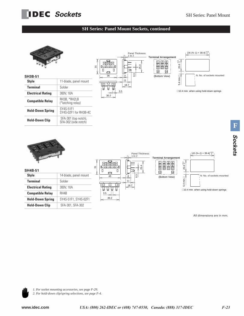
SH3B-51
Style 11-blade, panel mount
Terminal Solder
Electrical Rating 300V, 10A
Compatible Relay RH3B, *RH2LB (*latching relay)
Hold-Down Spring SY4S-51F1SY4S-02F1 for RH3B-4C
Hold-Down Clip SFA-301 (top notch), SFA-302 (side notch)
3
11
18.7
31
0.3
25.4
30.2
3.5
36
Panel Thickness:1 to 2 Terminal Arrangement
13
159
2
106
14
4
128
25.6
+0.
20
+0.50
∗ 10.4 min. when using hold-down springs
5.4
min
.∗ N: No. of sockets mounted
[36 (N–1) + 30.4]
(Bottom View)
SH Series: Panel Mount Sockets, continued
SH4B-51
Style 14-blade, panel mount
Terminal Solder
Electrical Rating 300V, 10A
Compatible Relay RH4B
Hold-Down Spring SY4S-51F1, SY4S-02F1
Hold-Down Clip SFA-301, SFA-302
3
11
18.7
31
0.3
25.4
39.2
45
3.5
Panel Thickness:1 to 2
13
159
3
117
14
4
128
2
106
Terminal Arrangement
25.6
+0.
20
+0.50
∗ 10.4 min. when using hold-down springs
5.4
min
.∗
N: No. of sockets mounted
[45 (N–1) + 39.4]
(Bottom View)
All dimensions are in mm.
1. For socket mounting accessories, see page F-29.2. For hold-down clip/spring selections, see page F-4.
SY Series: Panel Mount Sockets
F-24 www.idec.com USA: (800) 262-IDEC or (408) 747-0550, Canada: (888) 317-IDEC
F
So
ckets
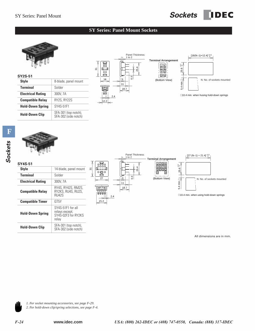
SY Series: Panel Mount Sockets
SY2S-51
Style 8-blade, panel mount
Terminal Solder
Electrical Rating 300V, 7A
Compatible Relay RY2S, RY22S
Hold-Down Spring SY4S-51F1
Hold-Down Clip SFA-301 (top notch), SFA-302 (side notch)
3
11
18.7
18
312.4
12.2
25.4
Panel Thickness:1 to 2
13
159
14
4812
Terminal Arrangement
∗ 10.4 min. when husing hold-down springs
+0.
20
+0.50[18(N–1)+12.4]
5.4
min
.∗25
.6
N: No. of sockets mounted0.3
(Bottom View)
SY4S-51
Style 14-blade, panel mount
Terminal Solder
Electrical Rating 300V, 7A
Compatible RelayRY4S, RY42S, RM2S, RY2KS, RU4S, RU2S, RU42S
Compatible Timer GT5Y
Hold-Down SpringSY4S-51F1 for all relays except;SY4S-02F3 for RY2KS relay
Hold-Down Clip SFA-301 (top notch), SFA-302 (side notch)
27
31
2.4
21.2
3
11
18.7
25.4
Panel Thickness:1 to 2
107
13 14
159
3
1284
62
11
Terminal Arrangement
25.6
0+0.5
+0.
20
∗ 10.4 min. when using hold-down springs
[27 (N–1) + 21.4]
5.4
min
.∗ N: No. of sockets mounted0.3
(Bottom View)
All dimensions are in mm.
1. For socket mounting accessories, see page F-29.2. For hold-down clip/spring selections, see page F-4.
Sockets SH Series: PCB Mount
www.idec.com USA: (800) 262-IDEC or (408) 747-0550, Canada: (888) 317-IDEC F-25
F
So
ckets
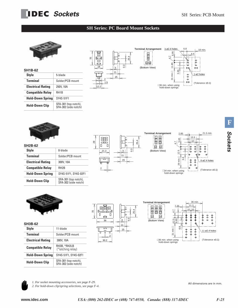
SH Series: PC Board Mount Sockets
SH1B-62
Style 5-blade
Terminal Solder/PCB mount
Electrical Rating 250V, 10A
Compatible Relay RH1B
Hold-Down Spring SY4S-51F1
Hold-Down Clip SFA-301 (top notch), SFA-302 (side notch)
3
11
15
18
31
0.3
25.4
12.2
1.52
13
159
14
Terminal Arrangement 18 min.
2-ø2 holes
3-ø2.4 holes
(Tolerance ±0.1)∗ 36 min. when using hold-down springs
31 m
in.∗
4.
7
4.4
6.8
5.95
6.95
11.8
5
(Bottom View)
SH2B-62
Style 8-blade
Terminal Solder/PCB mount
Electrical Rating 300V, 10A
Compatible Relay RH2B
Hold-Down Spring SY4S-51F1, SY4S-02F1
Hold-Down Clip SFA-301 (top notch), SFA-302 (side notch)
3
11
15
0.3
25.4
21.2
29
2
13
159
4
128
14
Terminal Arrangement
∗ 34 min. when using hold-down springs
21.5 min.
8-ø2.4 holes
(Tolerance ±0.1)
29
min
.∗4.
7
2.85
5.65
12.5
15.5
10
6.6
(Bottom View)
SH3B-62
Style 11-blade
Terminal Solder/PCB mount
Electrical Rating 300V, 10A
Compatible Relay RH3B, *RH2LB (*latching relay)
Hold-Down Spring SY4S-51F1, SY4S-02F1
Hold-Down Clip SFA-301 (top notch), SFA-302 (side notch)
3
11
15
31
0.3
25.4
30.2
36
2
13
159
2
106
14
4
128
Terminal Arrangement
∗ 36 min. when using hold-down springs
6.6
36 min.
11-ø2.4 holes
(Tolerance ±0.1)
31
min
.∗6.
6512
.5
21.3
10 10
7.35
4.7
(Bottom View)
1. For socket mounting accessories, see page F-29.2. For hold-down clip/spring selections, see page F-4.
All dimensions are in mm.
SH/SY Series: PCB Mount Sockets
F-26 www.idec.com USA: (800) 262-IDEC or (408) 747-0550, Canada: (888) 317-IDEC
F
So
ckets
SH Series: PC Board Mount Sockets, continued
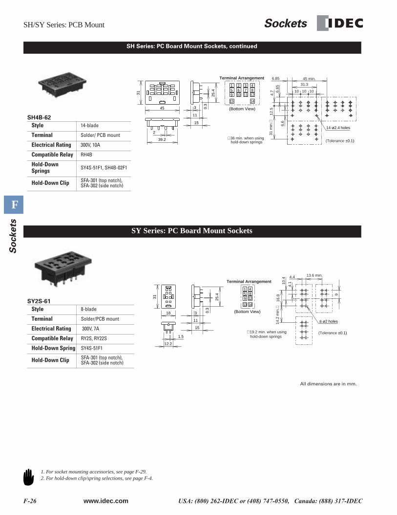
SH4B-62
Style 14-blade
Terminal Solder/ PCB mount
Electrical Rating 300V, 10A
Compatible Relay RH4B
Hold-Down Springs SY4S-51F1, SH4B-02F1
Hold-Down Clip SFA-301 (top notch), SFA-302 (side notch)
3
11
15
31
0.3
25.4
39.2
45
2
13
159
3
117
14
4
128
2
106
Terminal Arrangement 45 min.
14-ø2.4 holes
(Tolerance ±0.1)∗ 36 min. when using hold-down springs
31 m
in.∗
4.
7
31.3
6.85
6.6
6.65
12.5
10 10 10
(Bottom View)
SY Series: PC Board Mount Sockets
SY2S-61
Style 8-blade
Terminal Solder/PCB mount
Electrical Rating 300V, 7A
Compatible Relay RY2S, RY22S
Hold-Down Spring SY4S-51F1
Hold-Down Clip SFA-301 (top notch), SFA-302 (side notch)
3
11
15
18
31
12.2
25.4
1.5
4.4 13.6 min.
9
8-ø2 holes
(Tolerance ±0.1)∗ 19.2 min. when using hold-down springs
14.2
min
.∗
16.8
4.110
.4
13
159
14
4812
Terminal Arrangement
0.3
(Bottom View)
All dimensions are in mm.
1. For socket mounting accessories, see page F-29.2. For hold-down clip/spring selections, see page F-4.
Sockets SY Series: PCB Mount
www.idec.com USA: (800) 262-IDEC or (408) 747-0550, Canada: (888) 317-IDEC F-27
F
So
ckets
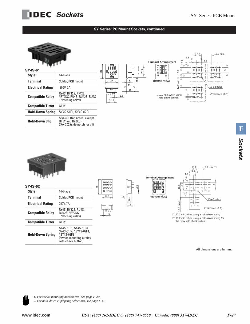
SY Series: PC Mount Sockets, continued
SY4S-61
Style 14-blade
Terminal Solder/PCB mount
Electrical Rating 300V, 7A
Compatible RelayRY4S, RY42S, RM2S, *RY2KS, RU4S, RU42S, RU2S (*latching relay)
Compatible Timer GT5Y
Hold-Down Spring SY4S-51F1, SY4S-02F1
Hold-Down ClipSFA-301 (top notch; except GT5Y and RY2KS)SFA-302 (side notch for all)
27
3121.2
3
11
15
0.3
25.4
1.5
107
13 14
159
3
1284
62
11
Terminal Arrangement 4.4
13.8 min.
9
15-ø2 holes
(Tolerance ±0.1)∗ 19.2 min. when using hold-down springs
14.2
min
.∗
16.8
4.1
10.4
8.8
13.2
1.4
(Bottom View)
SY4S-62
Style 14-blade
Terminal Solder/PCB mount
Electrical Rating 250V, 7A
Compatible RelayRY4S, RY42S, RU4S, RU42S, *RY2KS (*latching relay)
Compatible Timer GT5Y
Hold-Down Spring
SY4S-51F1, SY4S-51F3, SY4S-51F4, *SY4S-02F1, *SY4S-02F3 (*when mounting a relay with check button)
1.5
3
11
15
21.2
29 0.3
4.1
10.4
16.8
1.4
12.2
min
.∗
∗ 17.2 min. when using a hold-down spring.
∗∗ 13.2 min. when using a hold-down spring for the relay with check button.
(Tolerance ±0.1)
13.2 8.2 min.∗∗
4.48.8
15-ø2 holes
9
107
13 14
159
3
1284
62
11
Terminal Arrangement
(Bottom View)
All dimensions are in mm.
1. For socket mounting accessories, see page F-29.2. For hold-down clip/spring selections, see page F-4.
Other Sockets Sockets
F-28 www.idec.com USA: (800) 262-IDEC or (408) 747-0550, Canada: (888) 317-IDEC
F
So
ckets
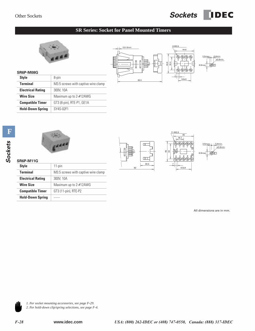
SR Series: Socket for Panel Mounted Timers
ø3.6min.
8-M3.5
2 1 8 7
3 4 5 6
6.9max.30.4
44.6
0.8~5mm
80.5
7
9.8x3
44.6
3.5max. 5.6min.
SR6P-M08G
Style 8-pin
Terminal M3.5 screws with captive wire clamp
Electrical Rating 300V, 10A
Wire Size Maximum up to 2-#12AWG
Compatible Timer GT3 (8-pin), RTE-P1, GE1A
Hold-Down Spring SY4S-02F1
SR6P-M11G
Style 11-pin
Terminal M3.5 screws with captive wire clamp
Electrical Rating 300V, 10A
Wire Size Maximum up to 2-#12AWG
Compatible Timer GT3 (11-pin), RTE-P2
Hold-Down Spring ------
ø3.6min.
11-M3.5
6.9max.
92
4 3 8 9 10
2 115
1 7 63.5max. 5.8min.
30.5 7
8.5x4
16.745
3445
All dimensions are in mm.
1. For socket mounting accessories, see page F-29.2. For hold-down clip/spring selections, see page F-4.
Sockets
Accessories
www.idec.com
USA: (800) 262-IDEC or (408) 747-0550, Canada: (888) 317-IDEC F-29
F
So
ckets
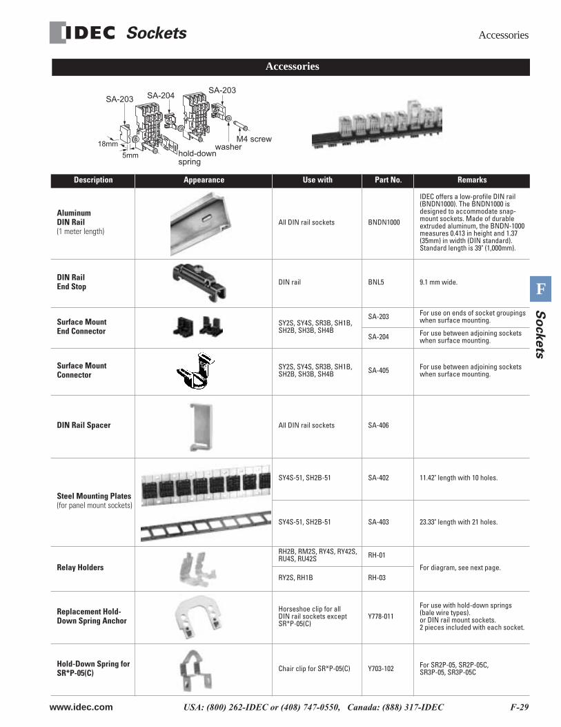
Description Appearance Use with Part No. Remarks
Aluminum DIN Rail
(1 meter length)
All DIN rail sockets BNDN1000
IDEC offers a low-profile DIN rail (BNDN1000). The BNDN1000 is designed to accommodate snap-mount sockets. Made of durable extruded aluminum, the BNDN-1000 measures 0.413 in height and 1.37 (35mm) in width (DIN standard). Standard length is 39" (1,000mm).
DIN Rail End Stop
DIN rail BNL5 9.1 mm wide.
Surface Mount End Connector
SY2S, SY4S, SR3B, SH1B, SH2B, SH3B, SH4B
SA-203 For use on ends of socket groupings when surface mounting.
SA-204 For use between adjoining sockets when surface mounting.
Surface Mount Connector
SY2S, SY4S, SR3B, SH1B, SH2B, SH3B, SH4B SA-405 For use between adjoining sockets
when surface mounting.
DIN Rail Spacer
All DIN rail sockets SA-406
Steel Mounting Plates
(for panel mount sockets)
SY4S-51, SH2B-51 SA-402 11.42" length with 10 holes.
SY4S-51, SH2B-51 SA-403 23.33" length with 21 holes.
Relay Holders
RH2B, RM2S, RY4S, RY42S, RU4S, RU42S RH-01
For diagram, see next page.RY2S, RH1B RH-03
Replacement Hold-Down Spring Anchor
Horseshoe clip for all DIN rail sockets except SR*P-05(C)
Y778-011For use with hold-down springs (bale wire types).or DIN rail mount sockets.2 pieces included with each socket.
Hold-Down Spring for SR*P-05(C)
Chair clip for SR*P-05(C) Y703-102 For SR2P-05, SR2P-05C, SR3P-05, SR3P-05C
Accessories
SA-203SA-203 SA-204
M4 screwwasher
hold-down spring
18mm
5mm
Instructions Sockets
F-30 www.idec.com USA: (800) 262-IDEC or (408) 747-0550, Canada: (888) 317-IDEC
F
So
ckets
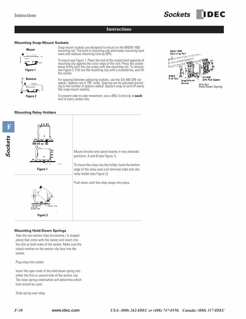
Mounting Snap-Mount Sockets
Mounting Relay Holders
Mounting Hold-Down Springs
Mount directly onto panel boards in two alternate positions: A and B (see Figure 1).
To mount the relay into the holder, hook the bottom edge of the relay case (coil terminal side) onto the relay holder (see Figure 2).
Push down until the relay snaps into place.
Take the two anchor clips (horseshoe / U-shaped piece) that come with the socket and insert into the slits on both sides of the socket. Make sure the raised notches on the anchor clip face into the socket.
Plug relay into socket
Insert the open ends of the hold-down spring into either the first or second hole of the anchor clip. The relay-spring combination will determine which hole should be used.
Slide spring over relay.
Hold-Down Spring
Instructions
Snap-mount sockets are designed to mount on the BNDN-1000 mounting rail. The built-in mounting clip eliminates mounting hard-ware and reduces mounting time by 80%.
To mount see Figure 1. Place the end of the socket (end opposite of mounting clip against the outer edge of the rail). Press the socket down firmly until the clip snaps onto the mounting rail. To remove see Figure 2. Pull out the mounting clip with a screwdriver, and lift the socket.
For spacing between adjoining sockets, use the SA-406 DIN rail spacer. Spacers are 0.195" wide. Spacing can be adjusted accord-ing to the number of spacers added. Spacers snap on and off easily like snap-mount sockets.
To prevent side-to-side movement, use a BNL-5 end clip at each end of every socket row.
Remove
Mount
Figure 1
Figure 2
Figure 1
RH-01 or -03
Figure 2
Sockets Dimensions
www.idec.com USA: (800) 262-IDEC or (408) 747-0550, Canada: (888) 317-IDEC F-31
F
So
ckets
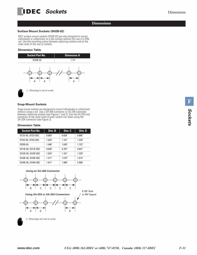
Surface Mount Sockets (SH2B-02)
Snap-Mount Sockets
Dimensions
IDEC surface mount sockets (SH2B-02) are also designed to mount individually or collectively on a flat surface without the use of a DIN rail. Use the mounting screw between adjoining sockets and at the outer ends of the row of sockets.
Dimension Table
Socket Part No. Dimension A
SH2B-02 1.14"
A A A
1. Drawing is not to scale.
Snap-mount sockets are designed to mount individually or collectively without using a rail. Use a SA-405 connector or SA-204 connector between adjoining sockets (see Figures 1 and 2). Use the SA-203 end connector at the outer ends of each socket row when using the SA-204 connector (see Figure 2).
Dimension Table
Socket Part No. Dim. B Dim. C Dim. D
SY2S-05, SY2S-05C 0.669" 0.826" 0.866"
SY4S-05, SY4S-05C 1.024" 1.181" 1.220"
SR3B-05 1.496" 1.693" 1.732"
SH1B-05, SH1B-05C 0.630" 0.787" 0.827"
SH2B-05, SH2B-05C 1.024" 1.181" 1.220"
SH3B-05, SH3B-05C 1.417" 1.575" 1.614"
SH4B-05, SH4B-05C 1.811" 1.969" 2.008"
B C CC C
D D D
0.165" Holeor M4 Tapped
Using an SA-406 Connector
Using SA-203 or SA-204 Connectors
2. Drawings are not to scale.
Dimensions Sockets
F-32 www.idec.com USA: (800) 262-IDEC or (408) 747-0550, Canada: (888) 317-IDEC
F
So
ckets
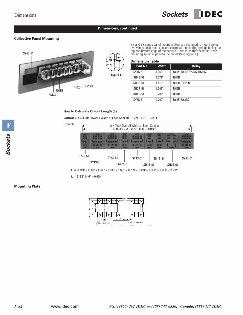
Collective Panel Mounting
Mounting Plate
Dimensions, continued
How to Calculate Cutout Length (L)
Cutout L = A (Total Overall Width of Each Socket) – 0.221" (+ 0", – 0.020")
Example:
L = [0.709" + 1.063" + 1.063" + 0.709" + 1.063" + 0.709" + 1.063" + 1.063"] – 0.221" = 7.93"
L = 7.93" (+ 0", – 0.020")
SH and SY series panel mount sockets are designed to mount collec-tively in panel cut-outs. Insert socket with mounting springs facing the top and bottom edge of the panel cut-out. Push the socket until the mounting spring clips onto the panel. (See Figure 1.)
Dimension Table
Part No. Width Relay
SY4S-51 1.063" RY4S, RY42, RY2KS, RM2S
SH4B-51 1.772" RH4B
SH3B-51 1.418" RH3B, RH2LB
SH2B-51 1.063" RH2B
SH1B-51 0.709" RH1B
SY2S-51 0.709" RY2S, RY22S
SY4S-51
RM2SRH1B
RH2B RY2KS
Figure 1
SH1B-51SY2S-51
SY4S-51SY4S-51
SY2S-51
SY4S-51
SH1B-51 SH2B-51
SY4S-51
A = Total Overall Width of Each SocketCutout L = A – 0.221" (+ 0", – 0.020")