Embed Size (px)
Citation preview
INSTRUCTIONS for
C-66 CUTTING TORCHES
F-805-SMay, 2009
Cutting Range using any fuel gas except acetylene ........................... 1/8"-20"Cutting Nozzels ................................................................................. 1500 seriesTorch-Hose Connections ....................................... Oxy.—CGA-022 (9/16"—18)
F.G.—CGA-023 (9/16"—18LH)Torch Overall Length .................................................................................. 21-in.Weight .................................................................................................... 3-1/2 lbs.
These INSTRUCTIONS are for experienced operators. If you are not fully familiar with the principles of operationand safe practices for oxy-fuel gas equipment, we urge you to read our booklet “Precautions and Safe Practicesfor Gas Welding, Cutting and Heating,” Form 2035. The same information appears in the “Oxy-Acetylene Hand-book” which may be purchased from any ESAB Distributor. Do NOT permit untrained persons to install, operate,or maintain this equipment. DO NOT attempt to install or operate this equipment until you have read and fullyunderstand these instructions. If you do not fully understand these instructions, contact your supplier for furtherinformation.
The cutting torches covered by these instructions are listed by third parties only when using parts manufacturedby ESAB Welding & Cutting Products to the specifications on file with third party listed, and when they are used inthe gas service for which they are designed and listed. The use of other parts that cause damage or failure to theequipment will void the manufacturer’s warranty.
3. Attach nozzle to torch head, and tighten connectionnut with a wrench.
4. Check throttle valve packing nuts for tightness.
ADJUSTING GAS PRESSURESFuel Gas: If fuel gas is supplied from a station outletwithout a regulator, merely open the station valve. If fuelgas is being supplied through a station or cylinder regu-lator, open the fuel gas valve on the torch, turn in thepressure-adjusting screw on the regulator until the regu-lator deliver-pressure gauge indicates the desired pres-sure (see chart on page 4). Then immediately close thefuel gas valve.
Oxygen: Open the cutting oxygen valve by depressingits valve lever fully. Turn in the pressure-adjusting screwuntil the regulator delivery-pressure gauge registers thedesired pressure (see cutting chart on page 4). Thenrelease the cutting oxygen lever.
NOTE: When gaugeless regulators are used, do notopen torch valves. Merely turn in the pressure-adjusting screws to the desired pressures asindicated on the scales of the regulator caps.
Be sure this information reaches the operator.You can get extra copies through your supplier.
OPERATING INSTRUCTIONS
The C-66 can be used with any fuel gas EXCEPTacetylene. Use of acetylene can cause a flashbackwhich can cause serious burns and damage thetorch.Be sure gas flow is sufficient for nozzle size.Adjust regulators for proper psig pressures.Adjust throttle valves properly.Keep torch in good repair.DO NOT throttle back gases to use large nozzle onthin material.
CONNECTING1. Attach regulator to the oxygen cylinder or station
valve; attach fuel gas regulator to cylinder or stationvalve unless fuel gas is to be supplied through ahydraulic or check valve from a pipeline at desiredpressure.
2. Attach oxygen hose to the oxygen regulator; attachfuel gas hose to the fuel gas station valve or regula-tor. Attach both hoses to torch. Tighten all connec-tions nuts with a wrench.
Be sure this information reaches the operator.You can get extra copies through Your supplier.
saVe these instructions!
important safeguarDsWhen using Oxy-Fuel Gas Torches, basic safety precautions should always be followed:
Never use Acetylene gas at a pressure over 15 psig.a. Never use damaged equipment.b. Never use oil or grease on or around Oxygen equipment.c. Never use Oxygen or fuel gas to blow dirt or dust off clothing or equipment.d. Never light a torch with matches or a lighter. Always use a striker.e. Always wear the proper welding goggles, gloves and clothing when operating Oxy-Acetylene equipment. f. Pants should not have cuffs.Do not carry lighters, matches or other flammable objects in pockets when welding or cutting.g. Always be aware of others around you when using a torch.h. Be careful not to let welding hoses come into contact with torch flame or sparks from cutting.i. SAVE THESE INSTRUCTIONS.j.
This equipment will perform in conformity with the description thereof contained in this manual and accompa-nying labels and/or inserts when installed, operated, maintained and repaired in accordance with the instruc-tions provided. This equipment must be checked periodically. Malfunctioning or poorly maintained equipment should not be used. Parts that are broken, missing, worn, distorted or contaminated should be replaced imme-diately. Should such repair or replacement become necessary, the manufacturer recommends that a telephone or written request for service advice be made to the Authorized Distributor from whom it was purchased.
This equipment or any of its parts should not be altered without the prior written approval of the manufacturer. The user of this equipment shall have the sole responsibility for any malfunction which results from improper use, faulty maintenance, damage, improper repair or alteration by anyone other than the manufacturer or a ser-vice facility designated by the manufacturer.
these instructions are for experienced operators. if you are not fully familiar with the prin-ciples of operation and safe practices for gas welding and cutting equipment, we urge you to read our booklet, “precautions and safe practices for gas Welding, cutting, and heating,” form f-2035. Do not permit untrained persons to install, operate, or maintain this equipment. Do not attempt to install or operate this equipment until you have read and fully understand these instructions. if you do not fully understand these instructions, contact your supplier for further information. Be sure to read the safety precautions before installing or operating this equipment.
caution
user responsiBilitY
reaD anD unDerstanD instruction manual Before installing or operating. protect Yourself anD others!
�
�������������� ����������������������� ����������������������� ����������������������������������� ��������������������������������������� ��������������������������������������������������� ����������������������������������� ����������� ������� �������������������� ����������������������������������������������������� �� ���������������!���������� ������� ��������������"�����������
�#$�%&��'$(#�%) ��*+�$�,%#����������������� �������������������� ��������������������-������������� �����,������� �� ����� �.��������� �������� ������� ��"�������� ��������� ��� ����������������� ������� �����������-������������������������!��� �����������/
�� ������������ ��������� ������������������������������������ ����������������������������������
�� ���������������� � ������������������������ �������� ������������ ���������������������� ��������������� � ���� ���� � ������ �� ����������� � �������������������������������������� � ��������� ����� ��� ����������
� !� ��������� ����������������������� ������������������ ��"���������������������� �� �������������� ������� ����� ����� ����� �����
#� $�� � � ��������������� �������� ����� ������������������ � �������� �����
%� &������������� ����������������������������������'��������������� ������ ������������������ �����(�� ����� ������ ������� ������ ��� ��� ��������
�#%���*+�%0�)$��$*�� ��,��� ������� ����� ���� ������������������� ���,��������������.� �������� ���������������1�������������������/
�� )������ ������ ����� �������� ���� ���� ��������������� ������ ��� ������� ����� � �������������� ��������'����� ����� ����� �������������� �������� ����������������������� ������ ������� ����������� ��
�� !� ���������� � ��������� �������������������������������������������������������������������� �����������*���� ��� �� ���������������� � ������� ���������� ���
� +��� ������ ������������� ���� �������� ��������� ���������������� ��� ���������� ��������� �� ������ ������ ��� ����������������������� �,���������+��� ���� �������������� ������-�����,�����
#� !�����, ���������������� ����������� �� ������������������� � ���� ���� � �� ����� �� ��� ��� ���, ���������(�������� �������� ����
%� �� ������ ������� ���������� �������� ����� �� �������� ���������� � ������������������� �����&������ ���������������
.� /������ ������������ ������� �0/$�" ������%�(�1/��$��� �����&���'� ������������$������2�������� �������� ���� �0� ����� /��$�� � ���������� ����(� �������$����3������*�4��.5�
(2%���*+�3��%���� ��������������������� ��������� ����������� ���� ��� ��������� �����������"����+������������������������������������������ ���������������/
�� ����������������� �� ��� ����� ������������ ������������������ ��� ��������+��� ������ ����������� ������������������6�� ��� ������� ��������6����������������������������������� ������������� ��� �������������+��� ��� ���������������� ���� ������
�� 7������������� ����������� ���� ���� � ����������� ���� ������������� ��� �� �� ��� ������� ����� �" ������� ������ ���������� �� ��������� ���� ����� ���������+��� ��� ��� ����� ������������������� ����� ��
� )�� ��0"78�"'" ������9#5�� ��� ����� ������������ ��� ��� �������� �����
%4(��2%*��2��*�%*�*&%��� ���������������������������-���������� ������� ������������������������� ��������������������.������!������������������ ��� �������"���������������������������������/
�� ������ ��� �������� ������� ������ � ��� ���� ���� ��������� ���� ������� ���������+��� ���� ���������������� ������������������ ������
�� :�����,����������� ��������������;������������ ��������������� ����� ������������� �������������� ���� ���������,����
� +��� ������������� ������������:������� ���� ������ ���� ����� ������������������������ ���������������� �� ���
#� :������� ������������ ������������������%� &������� ��� � � �� ����������+��� ������ � ��
���������
3���&')�*+%#�,�*+)�*3� ��3��� ��������� �������������� ��� ������� ��� �1������ !�������������������������� ��������!��!���������������!� �� �����"�������.�����������������/
�� &� ������������ ������������ ������������� ������� ����� �� ������ ����� ���� ���������������������+��� ������ ��� ����� ������� ���� ���������*��� ������������ ���������������� ����/������������ ���<����� ������ ��� ����������� ���� ������ �� � ������������
�� ���������������������������� ���� ������������� ��� ���� ������� ��������������������� ���������0������ �������� ����� ������ ��, ������ ������������ ������ ����������� �
� ����� �������������������������!�� �������� � �������������� ���� ����������������� �������� �����"��������������������������� ������� �����������������������������������
#� =��� ������������������ ��������������������������� ����������������� ����0��� �������������������
%� /������ ����� ������� ������� �';�" ������$���1$����� ���� ���"��!���������'�������;��� ��'��������>�������������������� �'�������;���������� ������ %?������+����!������������� ���@����4��
�++���$*�)��� %�'��* $#2���$*��� ������������������������������� � ��������1����������������� ������-����������.��������������������� �����5��� ������������������� � �������3���6��������&�����������,�����7�� ����89:;��3�������������������������������������!�����������!����� �������������������������
-����������������� ������������������������ ��������������"��� ��%%40���=?��)����*�����/= ��.����������� ����>�� �0"78��"9#5���1"�� ������������'� ���2��� ��"/#���1)�������"��$��� ������ �$������
��� ������������'� �����'�� ��������$�����-�� !��!��!�6������"��� ����28
� ��""$�1"��$��� ���2�)���� �������!��������
Used to call attention to immediate hazardswhich, if not avoided, will result in immediate,serious personal injury or loss of life.
Used to call attention to potential hazardswhich could result in personal injury or loss oflife.
Used to call attention to hazards which couldresult in minor personal injury.
This symbol appearing in this manual meansAttention! Be Alert! Your safety is involved.
���������
SAFETY PRECAUTIONS

3
3. Then open the cutting oxygen valve and adjustflames with preheat oxygen valve. Flames are hot-test when inner cones are shortest. Do not throttlethe fuel gas valve unless flames blow off or burnaway from end of nozzle.
NOTE: Because of the several factors involved (injec-tor, nozzle size, gas pressures) the adjustmentprocedures given above do not apply in all situ-ations. However, this is a good rule-of-thumb ifyou want preheat flames at maximum effective-ness. You should usually be able to keep onepreheat valve wide open if regulator oxygenpressure has been set correctly for the nozzlein use.
SHUTTING OFFRelease the cutting oxygen valve lever. Then close thefuel gas valve, and finally the preheat oxygen valve.
If operations are to be stopped for half-hour or more, allpressure should be released from the torch, hoses, andregulators by doing the following:
1. Close each cylinder or station valve.2. Open torch valves.3. After relieving the gases, back out the pressure-ad-
justing screw of each regulator and close the torchvalves.
OPERATING PRECAUTIONS
Backfire: Improper operation of the torch may causethe flames to go out with a loud “pop”. Such a backfiremay be caused by contact of nozzle with the work, byspatter from the work, by the use of incorrect gas pres-sures, or by leakage at the cutting nozzle seats due todirt or nicks on seats or to a loose nozzle nut.
Flashback: Under certain circumstances, the flame maynot “pop” out (backfire) but instead burn back inside thetorch with a shrill hissing or squeal. This is called a “flash-back”. A flashback should never occur if (1) the equip-ment is in good condition; (2) preheat ports on cuttingnozzles or welding tips are cleaned frequently; (3) oper-ating pressures are correct; and (4) throttle valves areadjusted properly. Should a flashback occur, IMMEDI-ATELY shut off the torch. Allow it to cool off for at least aminute. Then check your nozzle or tip, gas pressure,readjust regulators if necessary, and relight the torch. Ifflashback recurs, send the torch to your distributor or toESAB Remanufacturing Center, 411 S. Ebenezer Road,Florence, SC 29501 for repair.
TESTING FOR LEAKSEvery cutting outfit should be thoroughly tested for leaksafter it is first hooked up, and at regular intervals there-after. After all connections have been made, make sureall valves on the torch handle are closed. Then adjustregulators, or open station valves, to apply 60 psi oxy-gen pressure and up to 10 psi fuel gas pressure on thehoses.
Using Leak Test Solution (P/N 998771), or any othersolution suitable for oxygen service, check for leaks atthe cylinder valves, the cylinder-to-regulator connections,the regulator-to-hose connections, and the hose-to-torchconnections. If bubbling at any point indicates leakage,tighten the connection. If this does not stop the leakage,close the appropriate cylinder valve, open the corre-sponding torch valve to remove all pressure from theline, and finally release the regulator pressure-adjustingscrew by turning it counterclockwise; then break theleaky connection, wipe metal seating surfaces with aclean dry cloth, and examine them for nicks andscratches. Remake the connection(s) and retest. Do nottry to light the torch until you are satisfied that all con-nections are gas-tight.
After lighting the torch and adjusting the flames, use leaktest solution to check for leakage at all torch valves andat the nozzle nut.
LIGHTING AND FLAME ADJUSTMENT
With Low-Pressure Natural Gas (Torch equippedwith injector 01Y56, 01Y57, or 01Y61)
1. Open the preheat oxygen valve wide (two turns).2. Open the fuel gas valve about one turn and light the
gas at the nozzle with a friction lighter. DO NOT USEA MATCH. Use of a match can seriously burn yourhand.
3. Then open the cutting oxygen valve and adjustflames with the fuel gas valve. Flames are hottestwhen inner cones are shortest. Do not throttle thepreheat oxygen valve unless flames blow off, or burnaway from the nozzle.
With Medium-Pressure Natural Gas (Torch equippedwith injector 01Y58):
1. Open the preheat oxygen valve one turn or less.2. Open the fuel gas valve wide (two turns) and light
the gas at the nozzle with a friction lighter. DO NOTUSE A MATCH. Use of a match can seriously burnyour hand.

4
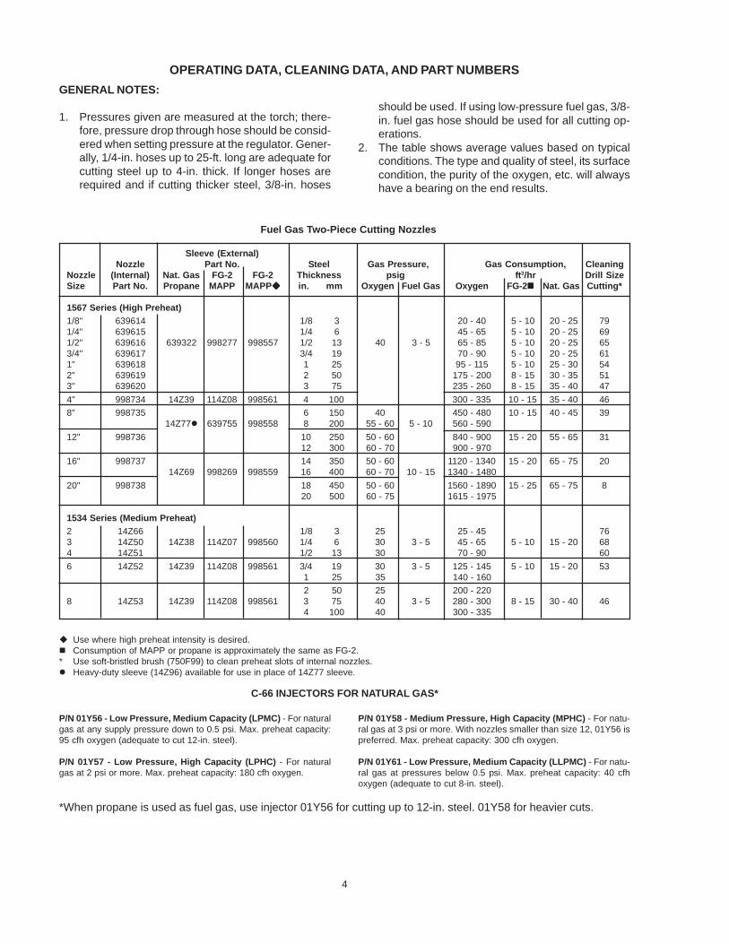
OPERATING DATA, CLEANING DATA, AND PART NUMBERS
GENERAL NOTES:
1. Pressures given are measured at the torch; there-fore, pressure drop through hose should be consid-ered when setting pressure at the regulator. Gener-ally, 1/4-in. hoses up to 25-ft. long are adequate forcutting steel up to 4-in. thick. If longer hoses arerequired and if cutting thicker steel, 3/8-in. hoses
should be used. If using low-pressure fuel gas, 3/8-in. fuel gas hose should be used for all cutting op-erations.
2. The table shows average values based on typicalconditions. The type and quality of steel, its surfacecondition, the purity of the oxygen, etc. will alwayshave a bearing on the end results.
Fuel Gas Two-Piece Cutting Nozzles
Sleeve (External)Nozzle Part No. Steel Gas Pressure, Gas Consumption, Cleaning
Nozzle (Internal) Nat. Gas FG-2 FG-2 Thickness psig ft3/hr Drill SizeSize Part No. Propane MAPP MAPP in. mm Oxygen Fuel Gas Oxygen FG-2 Nat. Gas Cutting*
1567 Series (High Preheat)
1/8" 639614 1/8 3 20 - 40 5 - 10 20 - 25 791/4" 639615 1/4 6 45 - 65 5 - 10 20 - 25 691/2" 639616 639322 998277 998557 1/2 13 40 3 - 5 65 - 85 5 - 10 20 - 25 653/4" 639617 3/4 19 70 - 90 5 - 10 20 - 25 611" 639618 1 25 95 - 115 5 - 10 25 - 30 542" 639619 2 50 175 - 200 8 - 15 30 - 35 513" 639620 3 75 235 - 260 8 - 15 35 - 40 47
4" 998734 14Z39 114Z08 998561 4 100 300 - 335 10 - 15 35 - 40 46
8" 998735 6 150 40 450 - 480 10 - 15 40 - 45 3914Z77 639755 998558 8 200 55 - 60 5 - 10 560 - 590
12" 998736 10 250 50 - 60 840 - 900 15 - 20 55 - 65 3112 300 60 - 70 900 - 970
16" 998737 14 350 50 - 60 1120 - 1340 15 - 20 65 - 75 2014Z69 998269 998559 16 400 60 - 70 10 - 15 1340 - 1480
20" 998738 18 450 50 - 60 1560 - 1890 15 - 25 65 - 75 820 500 60 - 75 1615 - 1975
1534 Series (Medium Preheat)
2 14Z66 1/8 3 25 25 - 45 763 14Z50 14Z38 114Z07 998560 1/4 6 30 3 - 5 45 - 65 5 - 10 15 - 20 684 14Z51 1/2 13 30 70 - 90 60
6 14Z52 14Z39 114Z08 998561 3/4 19 30 3 - 5 125 - 145 5 - 10 15 - 20 531 25 35 140 - 160
2 50 25 200 - 2208 14Z53 14Z39 114Z08 998561 3 75 40 3 - 5 280 - 300 8 - 15 30 - 40 46
4 100 40 300 - 335
Use where high preheat intensity is desired. Consumption of MAPP or propane is approximately the same as FG-2.* Use soft-bristled brush (750F99) to clean preheat slots of internal nozzles. Heavy-duty sleeve (14Z96) available for use in place of 14Z77 sleeve.
C-66 INJECTORS FOR NATURAL GAS*
P/N 01Y58 - Medium Pressure, High Capacity (MPHC) - For natu-ral gas at 3 psi or more. With nozzles smaller than size 12, 01Y56 ispreferred. Max. preheat capacity: 300 cfh oxygen.
P/N 01Y61 - Low Pressure, Medium Capacity (LLPMC) - For natu-ral gas at pressures below 0.5 psi. Max. preheat capacity: 40 cfhoxygen (adequate to cut 8-in. steel).
P/N 01Y56 - Low Pressure, Medium Capacity (LPMC) - For naturalgas at any supply pressure down to 0.5 psi. Max. preheat capacity:95 cfh oxygen (adequate to cut 12-in. steel).
P/N 01Y57 - Low Pressure, High Capacity (LPHC) - For naturalgas at 2 psi or more. Max. preheat capacity: 180 cfh oxygen.
*When propane is used as fuel gas, use injector 01Y56 for cutting up to 12-in. steel. 01Y58 for heavier cuts.

5
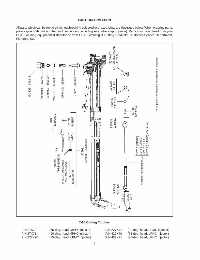
4. Remove the internal O-ring (85W10) from the guideand insert a new O-ring. Replace the external O-ring (86W70) if it shows distinct signs of wear.
5. Reassemble by placing retaining washer and springin guide, then placing stem through spring and O-ring in guide.
6. Screw valve assembly into body. Before reassem-bling cutting lever, connect torch to oxygen source,apply at least 60 psi pressure, and check for leak-age through the valve, around the stem, and aroundthe guide.
7. Reassemble cutting lever to torch.
Injector: To remove the injector for inspection or re-placement, first unscrew the injector chamber plug andremove the injector spring. Then run a long No. 10—32machine screw into the threads in the end of the injec-tor and withdraw the injector by pulling on the screw.
Before reinstalling a previously-used injector, be surethat the O-rings at each end of the injector assemblyare in good condition. Replace them if necessary. Alsobe sure the injector chamber plug is fitted with an O-ring in good condition (even in cases where the plugcarried no O-ring originally).
Cleaning Cutting Nozzles: Cutting nozzle orificesshould be cleaned by hand using OXWELD tip clean-ers, whenever a flame distortion is noticed. Maintain-ing clean orifices is highly recommended for reducingany incidence of flashbacks. If you do not have tip clean-ers, twist drills of the correct sizes (see table on pg. 4)may be used. Insert the drill carefully, and push it back
and forth. DO NOT TWIST THE DRILL.
To clean the preheat slots on internal nozzles, removethe external sleeve and use a soft bristled brush(750F99).
MAINTENANCE INSTRUCTIONS
For all repairs other than those covered below, send theapparatus to the nearest ESAB distributor or to ESABRemanufacturing Center, 411 S. Ebenezer Road, Flo-rence, SC 29501. Improperly repaired apparatus is haz-ardous.
Preheat Valves: Leakage around either throttle valvecan usually be corrected by tightening packing nutslightly. If this does not stop the leakage, replace thevalve assembly.
If either preheat valve fails to shut off completely, re-move the valve assembly from the torch. With cleancloth, wipe the ball in the end of the stem. Then reinsertvalve assembly and tighten it several times with maxi-mum force. If this does not eliminate leakage, try a newvalve assembly. If then the valve does not shut off com-pletely, send the torch to a repair station for reseating ofthe body.
After installing a new throttle valve assembly, tighten thepacking nut until the valve can be turned only with greatdifficulty, and set the unit aside, for three or four hours atleast, to set the packing. Then back off the packing nutuntil the valve turns readily.
Cutting Valve: If leakage develops around the cuttingvalve stem or between the cutting valve guide and thetorch body, or if the cutting valve fails to shut off com-pletely, proceed as follows:
1. Remove cutting valve lever by merely driving outthe fulcrum spiral-pin, using a drill or piece of rod (7/32-in. dia. or smaller).
2. Unscrew cutting valve guide and lift out entire valveassembly: guide (with external and internal O-rings)valve stem, spring, and O-ring retaining washer.
3. Pull stem out of guide. Replace it with new part un-less the molded rubber seat appears to be in excel-lent condition.
6
GU
IDE
- 6
38243
“O”R
ING
- 8
6W
70
“O”R
ING
- 8
5W
10
WA
SH
ER
- 6
38241
SP
RIN
G -
29
Z9
7
ST
EM
- 6
38891
50
Z3
8T
HU
MB
PIE
CE
DR
ILL A
T A
SS
EM
BLY
#52 (
.0635)
DR
ILL
PIN
62
32
-00
09
PIN
62
39
90
01
50
Z3
7L
AT
CH
51
Z3
1IN
SE
RT
63
89
81
LE
VE
R A
SS
EM
BLY
18
7W
01
“O”R
ING
7/8
-20
33
A5
6N
UT
*IN
JE
CT
OR
AS
SE
M.
01Y
58 (
MP
HC
)01Y
56 (
LP
MC
)01Y
57 (
LP
HC
)0
1Y
61
(L
LP
MC
) -
Op
tio
na
l
86
W0
4“O
”RIN
G
40
A3
9S
PR
ING8
6W
85
“O”R
ING
13
4Z
55
PLU
G
(2)
54A
87
TH
RO
TT
LE
VA
LVE
AS
SE
M.
*See p
age 4
for
deta
iled d
esc
riptio
n o
n inje
ctors
.
PARTS INFORMATION
All parts which can be replaced without breaking soldered or brazed joints are illustrated below. When ordering parts,please give both part number and description (including size, where appropriate). Parts may be ordered from yourESAB welding equipment distributor or from ESAB Welding & Cutting Products, Customer Service Department,Florence, SC.
C-66 Cutting Torches
P/N 27X70 (75-deg. head, MPHC Injector) P/N 227X71 (90-deg. head, LPMC Injector)P/N 27X71 (90-deg. head MPHC Injector) P/N 427X70 (75-deg. head, LPHC Injector)P/N 227X70 (75-deg. head, LPMC Injector) P/N 427X71 (90-deg. head, LPHC Injector)

7
F-805-S 05 / 2009 Printed in U.S.A.
OXWELD and PUROX are registered trademarks of ESAB Welding & Cutting Products.
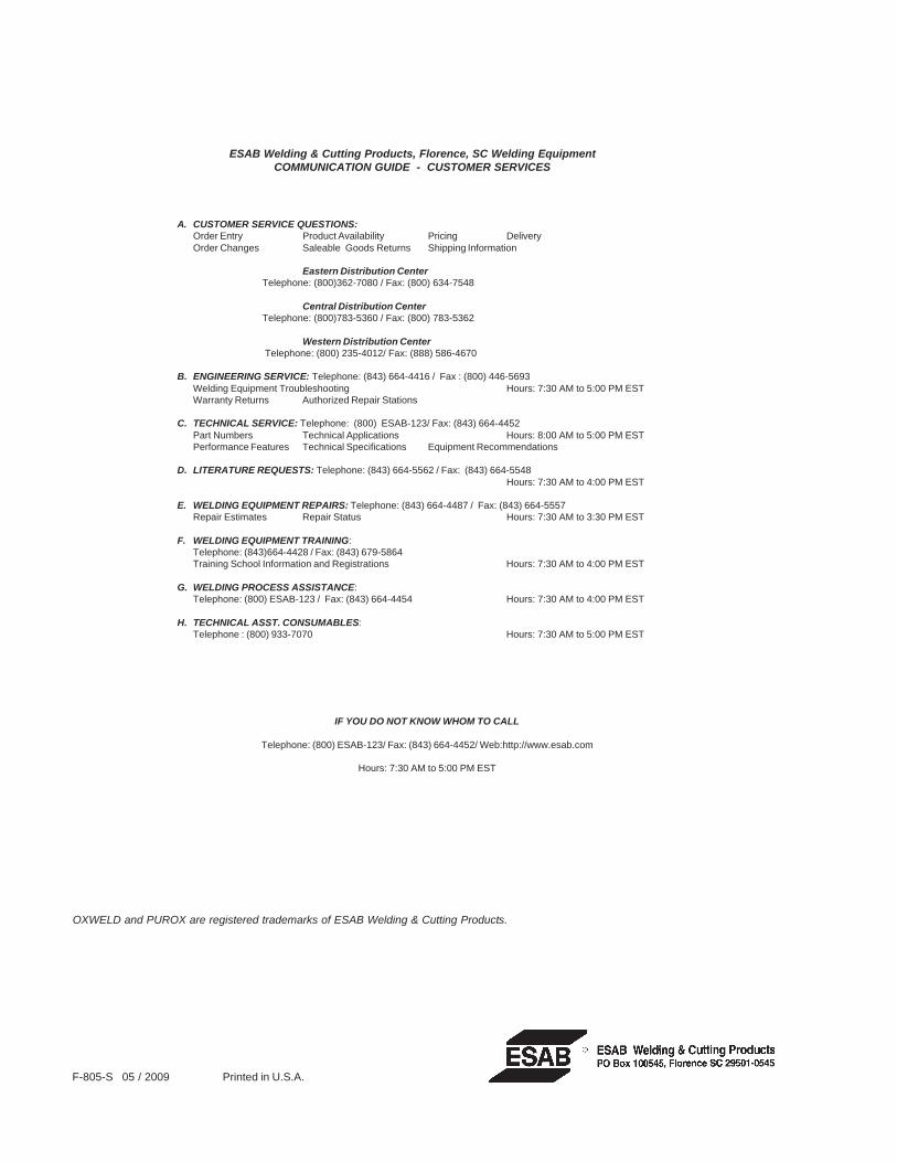
IF YOU DO NOT KNOW WHOM TO CALL
Telephone: (800) ESAB-123/ Fax: (843) 664-4452/ Web:http://www.esab.com
Hours: 7:30 AM to 5:00 PM EST
A. CUSTOMER SERVICE QUESTIONS:Order Entry Product Availability Pricing DeliveryOrder Changes Saleable Goods Returns Shipping Information
Eastern Distribution Center Telephone: (800)362-7080 / Fax: (800) 634-7548
Central Distribution Center Telephone: (800)783-5360 / Fax: (800) 783-5362
Western Distribution Center Telephone: (800) 235-4012/ Fax: (888) 586-4670
B. ENGINEERING SERVICE: Telephone: (843) 664-4416 / Fax : (800) 446-5693Welding Equipment Troubleshooting Hours: 7:30 AM to 5:00 PM ESTWarranty Returns Authorized Repair Stations
C. TECHNICAL SERVICE: Telephone: (800) ESAB-123/ Fax: (843) 664-4452Part Numbers Technical Applications Hours: 8:00 AM to 5:00 PM ESTPerformance Features Technical Specifications Equipment Recommendations
D. LITERATURE REQUESTS: Telephone: (843) 664-5562 / Fax: (843) 664-5548Hours: 7:30 AM to 4:00 PM EST
E. WELDING EQUIPMENT REPAIRS: Telephone: (843) 664-4487 / Fax: (843) 664-5557Repair Estimates Repair Status Hours: 7:30 AM to 3:30 PM EST
F. WELDING EQUIPMENT TRAINING:Telephone: (843)664-4428 / Fax: (843) 679-5864Training School Information and Registrations Hours: 7:30 AM to 4:00 PM EST
G. WELDING PROCESS ASSISTANCE:Telephone: (800) ESAB-123 / Fax: (843) 664-4454 Hours: 7:30 AM to 4:00 PM EST
H. TECHNICAL ASST. CONSUMABLES:Telephone : (800) 933-7070 Hours: 7:30 AM to 5:00 PM EST
ESAB Welding & Cutting Products, Florence, SC Welding EquipmentCOMMUNICATION GUIDE - CUSTOMER SERVICES