Embed Size (px)
Citation preview
HERZ F 4007
Page 1
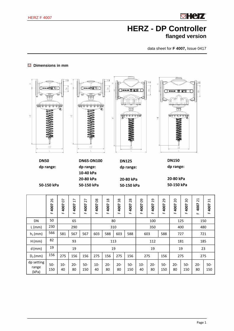
HERZ - DP Controller flanged version
data sheet for F 4007, Issue 0417
Dimensions in mm
F 40
07 2
6
F 40
07 0
7
F 40
07 1
7
F 40
07 2
7
F 40
07 0
8
F 40
07 1
8
F 40
07 3
8
F 40
07 2
8
F 40
07 0
9
F 40
07 1
9
F 40
07 2
9
F 40
07 2
0
F 40
07 3
0
F 4
007
21
F 40
07 3
1
DN 50 65 80 100 125 150
L (mm) 230 290 310 350 400 480
h1 (mm) 566 581 567 567 603 588 603 588 603 588 727 721
H (mm) 82 93 113 112 181 185
d (mm) 19 19 19 19 19 23
D2 (mm) 156 275 156 156 275 156 275 156 275 156 275 275
dp setting range (kPa)
50-150
10-40
20-80
50-150
10-40
20-80
20-80
50-150
10-40
20-80
50-150
20-80
50-150
20-80
50-150
DN65-DN100 dp range: 10-40 kPa 20-80 kPa 50-150 kPa
DN125 dp range: 20-80 kPa 50-150 kPa
DN150 dp range: 20-80 kPa 50-150 kPa
DN50 dp range: 50-150 kPa
HERZ F 4007
Page 2
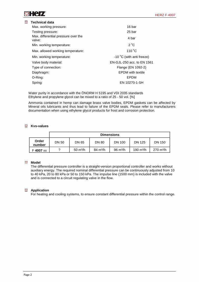
Technical data Max. working pressure: 16 bar Testing pressure: 25 bar Max. differential pressure over the valve: 4 bar
Min. working temperature: 2 oC
Max. allowed working temperature: 110 oC
Min. working temperature: -10 oC (with anti freeze) Valve body material: EN-GJL-250 acc. to EN 1561 Type of connection: Flange (EN 1092-2) Diaphragm: EPDM with textile O-Ring: EPDM Spring: EN 10270-1-SH
Water purity in accordance with the ÖNORM H 5195 and VDI 2035 standards Ethylene and propylene glycol can be mixed to a ratio of 25 - 50 vol. [%]
Ammonia contained in hemp can damage brass valve bodies, EPDM gaskets can be affected by Mineral oils lubricants and thus lead to failure of the EPDM seals. Please refer to manufacturers documentation when using ethylene glycol products for frost and corrosion protection.
Kvs-values
Dimensions
Order number
DN 50 DN 65 DN 80 DN 100 DN 125 DN 150
F 4007 xx ? 50 m³/h 84 m³/h 96 m³/h 190 m³/h 270 m³/h
Model The differential pressure controller is a straight-version proportional controller and works without auxiliary energy. The required nominal differential pressure can be continuously adjusted from 10 to 40 kPa, 20 to 80 kPa or 50 to 150 kPa. The impulse line (1500 mm) is included with the valve and is connected to a circuit regulating valve in the flow.
Application
For heating and cooling systems, to ensure constant differential pressure within the control range.
HERZ F 4007
Page 3
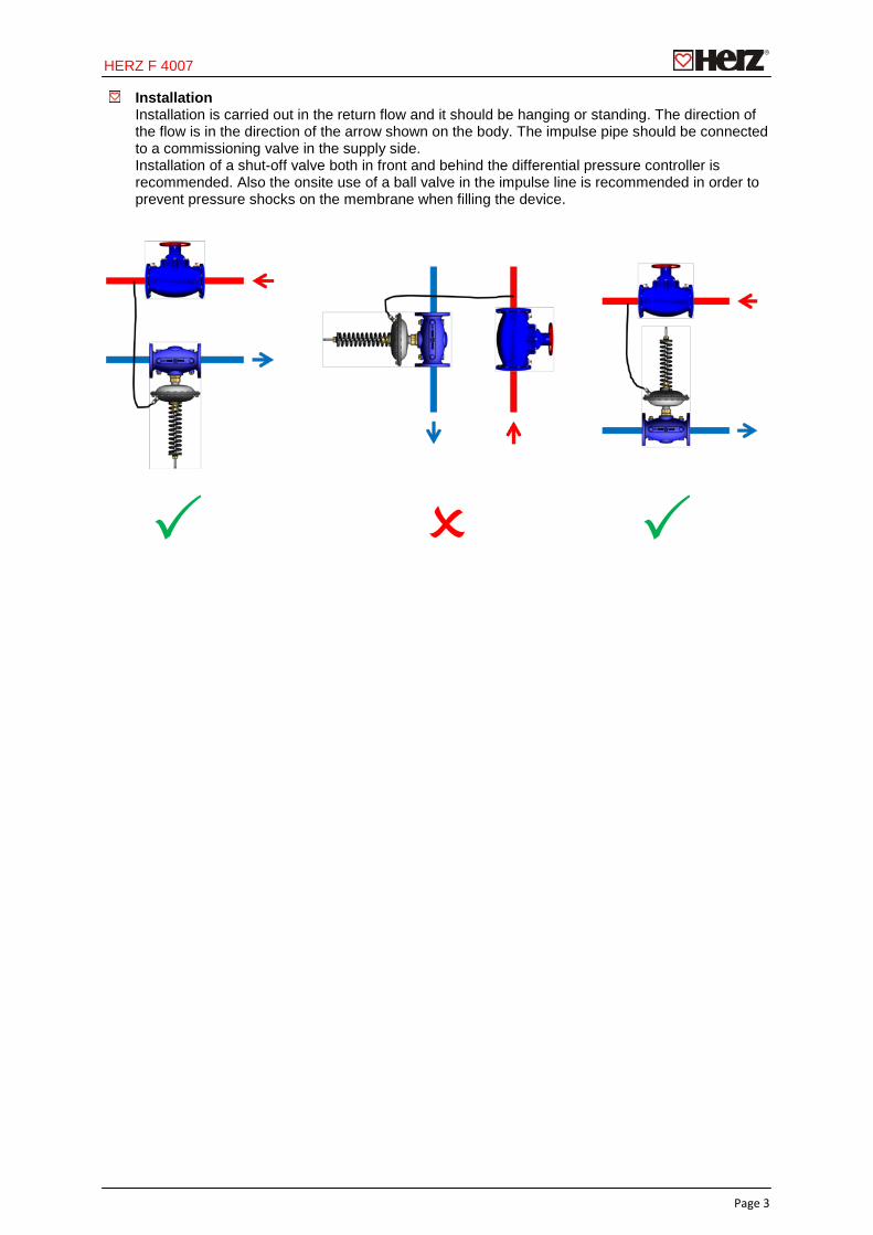
Installation Installation is carried out in the return flow and it should be hanging or standing. The direction of the flow is in the direction of the arrow shown on the body. The impulse pipe should be connected to a commissioning valve in the supply side. Installation of a shut-off valve both in front and behind the differential pressure controller is recommended. Also the onsite use of a ball valve in the impulse line is recommended in order to prevent pressure shocks on the membrane when filling the device.

HERZ F 4007
Page 4
Presetting The desired differential pressure is set by adjusting the spring. The setting range in the diagrams is in millimetre.
All specifications and statements within this document are according to information available at the time of printing and meant for informational purpose only. Herz Armaturen reserves the right to modify and change products as well as its technical specifications and/or its functioning according to technological progress and requirements. It is understood that all images of Herz products are symbolic representations and therefore may visually differ from the actual product. Colours may differ due to printing technology used. In case of any further questions do not hesitate to contact your closest HERZ Branch-office.
265
mm
diffe
rent
ial p
ress
ure
[kPa
]
flow rate [l/h]
HERZ F 4007
Page 5
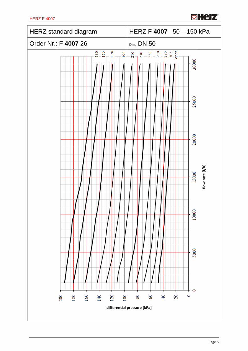
HERZ standard diagram HERZ F 4007 50 – 150 kPa
Order Nr.: F 4007 26 Dim. DN 50
flow
rate
[l/h
]
differential pressure [kPa]
HERZ F 4007
Page 6
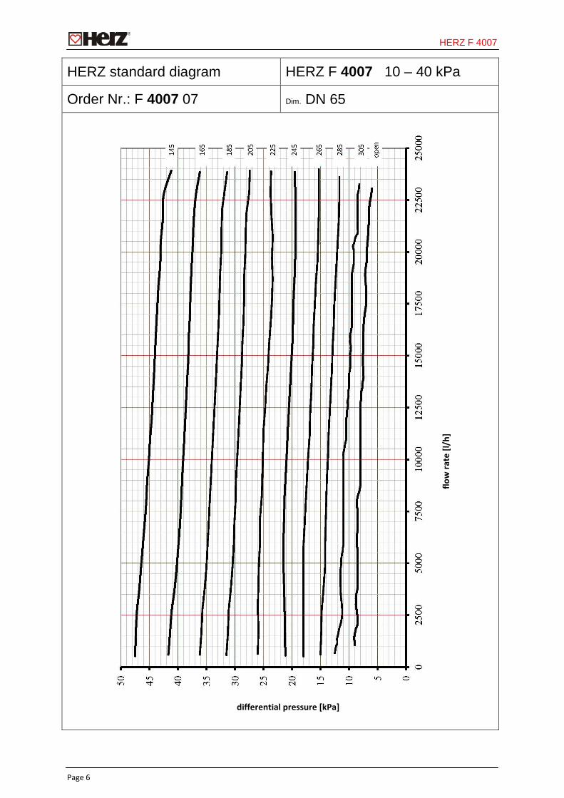
HERZ standard diagram HERZ F 4007 10 – 40 kPa
Order Nr.: F 4007 07 Dim. DN 65
flow
rate
[l/h
]
differential pressure [kPa]
HERZ F 4007
Page 7
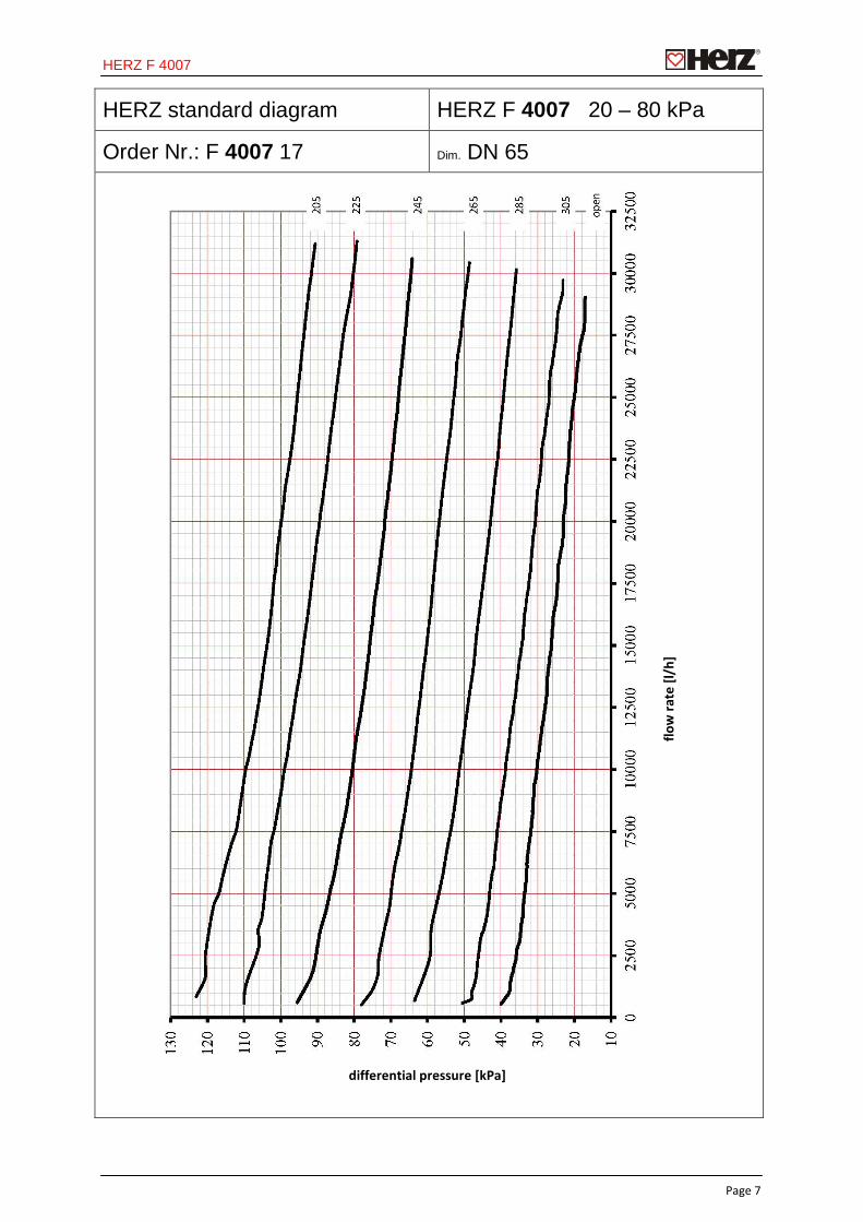
HERZ standard diagram HERZ F 4007 20 – 80 kPa
Order Nr.: F 4007 17 Dim. DN 65
flow
rate
[l/h
]
differential pressure [kPa]
HERZ F 4007
Page 8
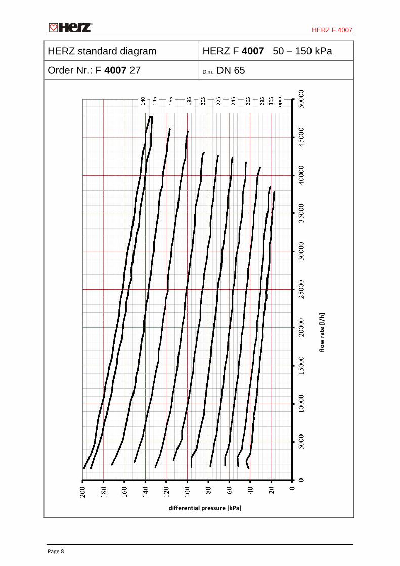
HERZ standard diagram HERZ F 4007 50 – 150 kPa
Order Nr.: F 4007 27 Dim. DN 65
flow
rate
[l/h
]
differential pressure [kPa]
HERZ F 4007
Page 9
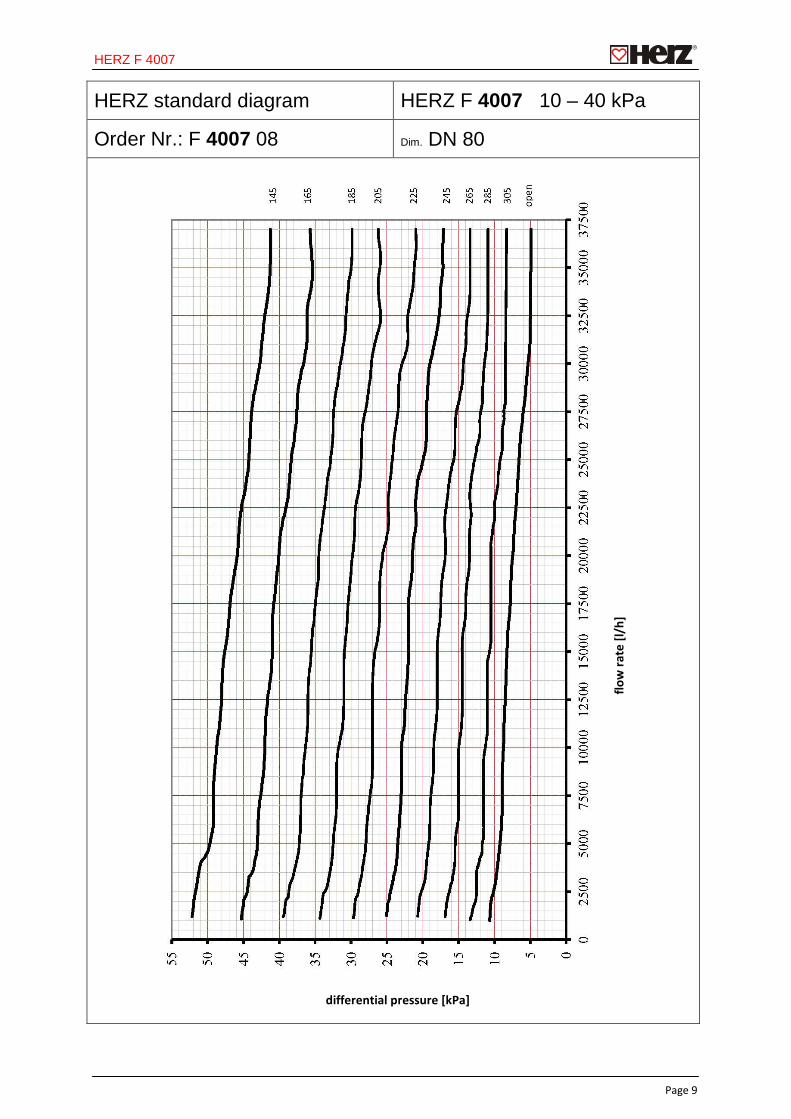
HERZ standard diagram HERZ F 4007 10 – 40 kPa
Order Nr.: F 4007 08 Dim. DN 80
flow
rate
[l/h
]
differential pressure [kPa]
HERZ F 4007
Page 10
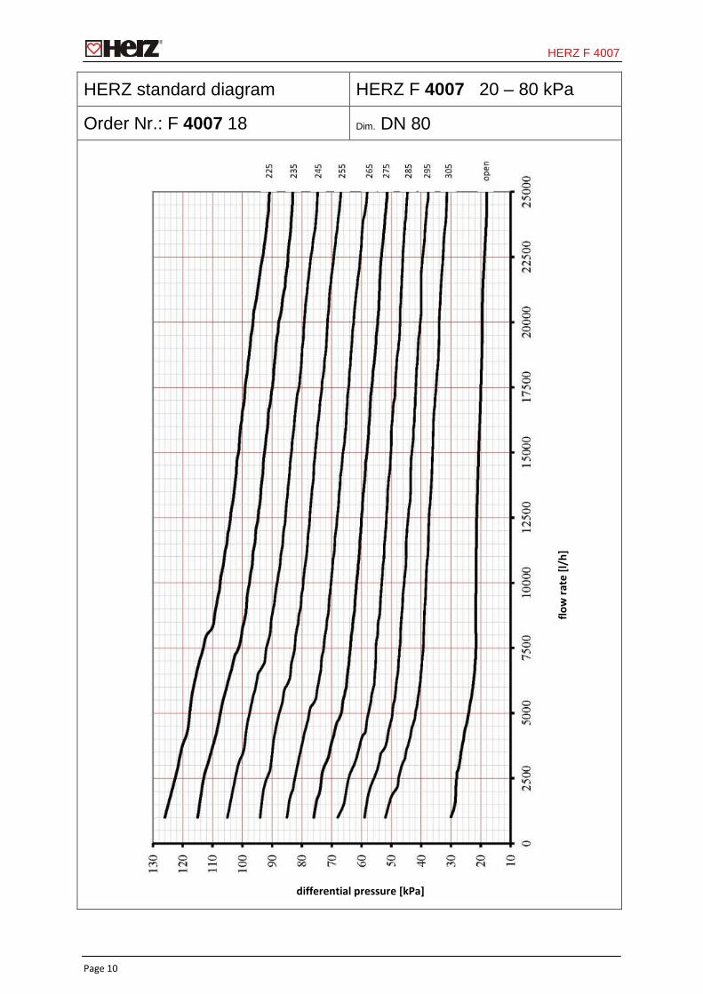
HERZ standard diagram HERZ F 4007 20 – 80 kPa
Order Nr.: F 4007 18 Dim. DN 80
flow
rate
[l/h
]
differential pressure [kPa]
HERZ F 4007
Page 11
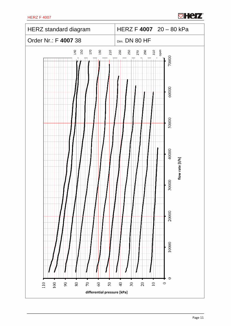
HERZ standard diagram HERZ F 4007 20 – 80 kPa
Order Nr.: F 4007 38 Dim. DN 80 HF
flow
rate
[l/h
]
differential pressure [kPa]

HERZ F 4007
Page 12
HERZ standard diagram HERZ F 4007 50 – 150 kPa
Order Nr.: F 4007 28 Dim. DN 80
flow
rate
[l/h
]
differential pressure [kPa]
HERZ F 4007
Page 13
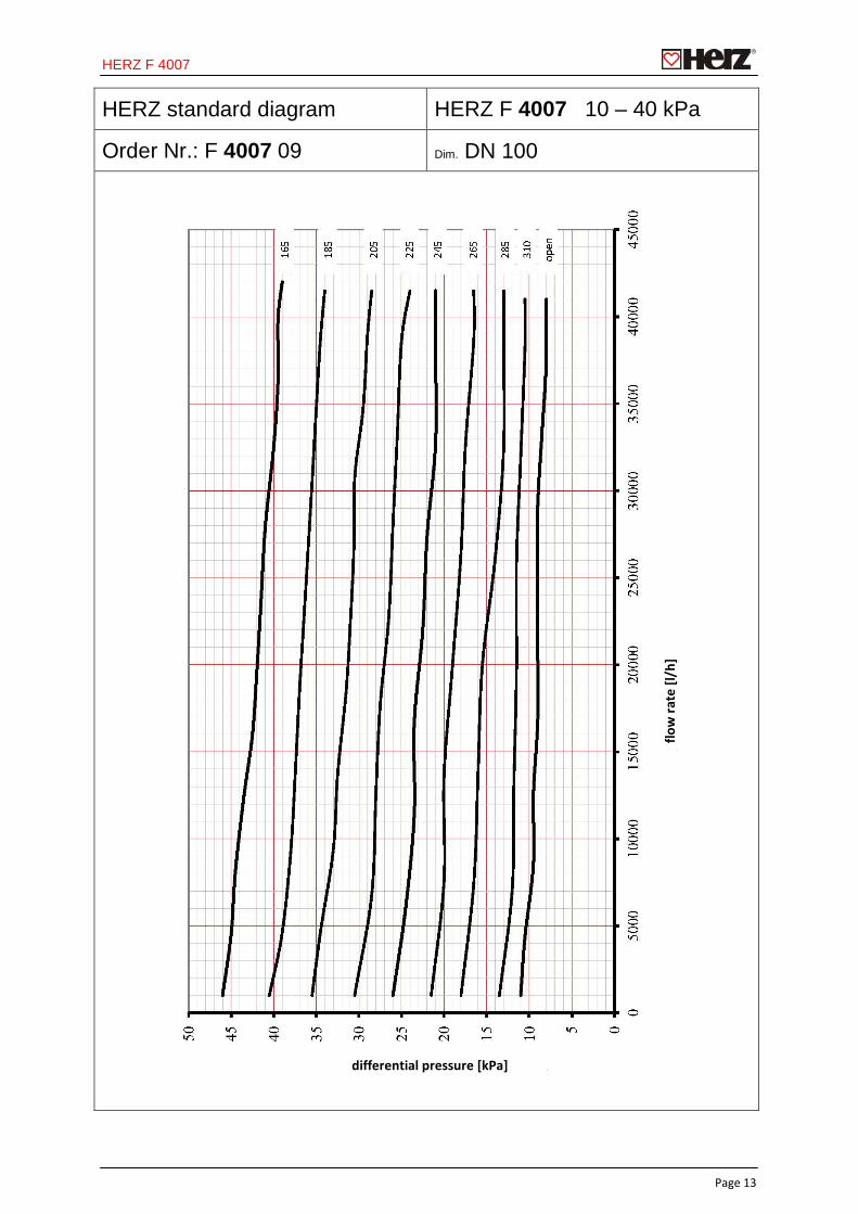
HERZ standard diagram HERZ F 4007 10 – 40 kPa
Order Nr.: F 4007 09 Dim. DN 100
flow
rate
[l/h
]
differential pressure [kPa]
HERZ F 4007
Page 14
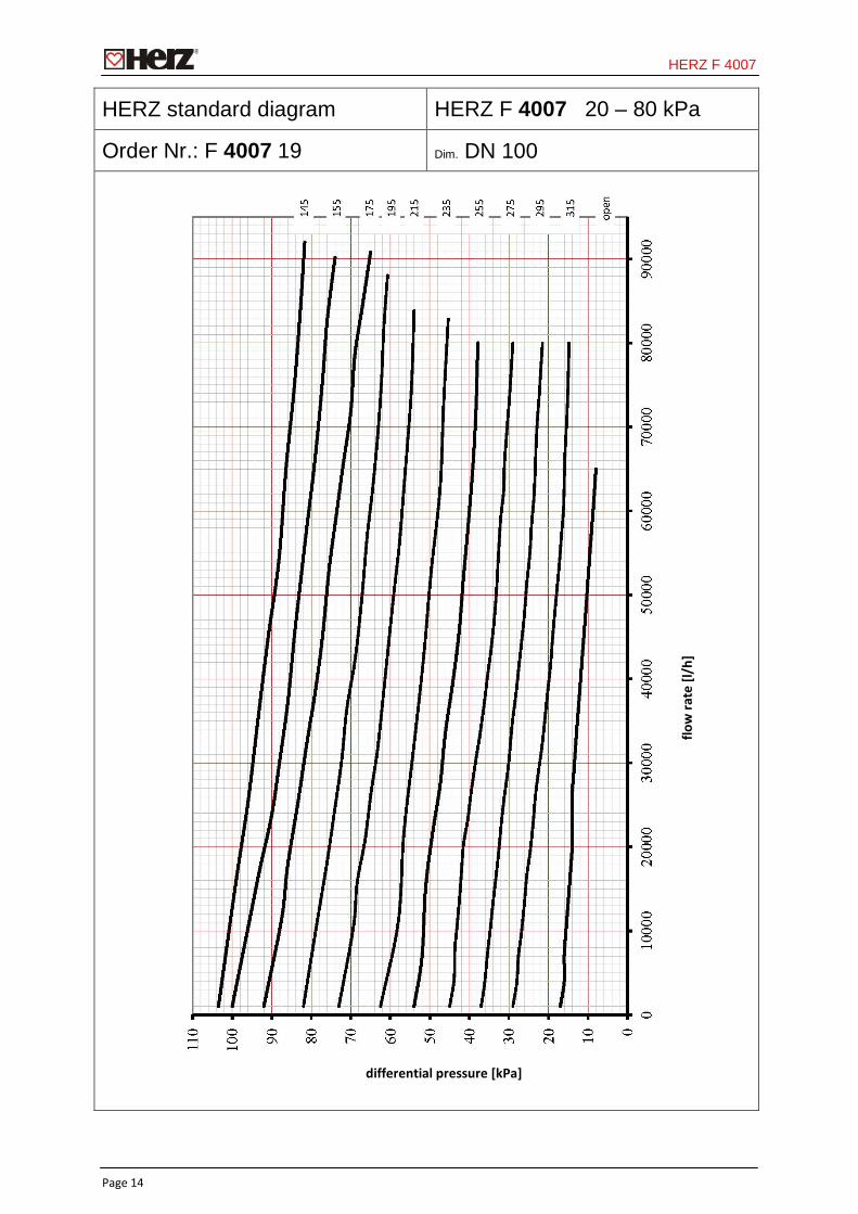
HERZ standard diagram HERZ F 4007 20 – 80 kPa
Order Nr.: F 4007 19 Dim. DN 100
flow
rate
[l/h
]
differential pressure [kPa]
HERZ F 4007
Page 15
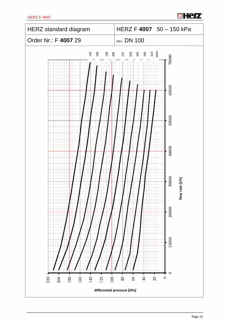
HERZ standard diagram HERZ F 4007 50 – 150 kPa
Order Nr.: F 4007 29 Dim. DN 100
flow
rate
[l/h
]
differential pressure [kPa]
HERZ F 4007
Page 16
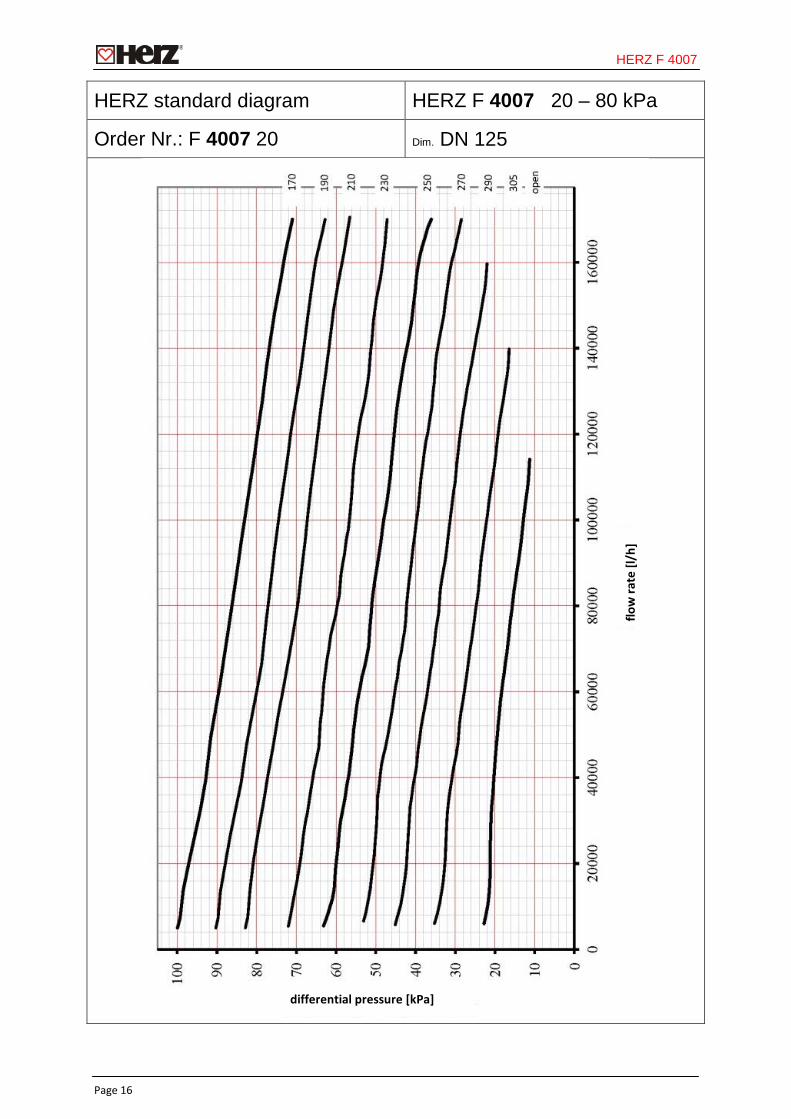
HERZ standard diagram HERZ F 4007 20 – 80 kPa
Order Nr.: F 4007 20 Dim. DN 125
flow
rate
[l/h
]
differential pressure [kPa]
HERZ F 4007
Page 17
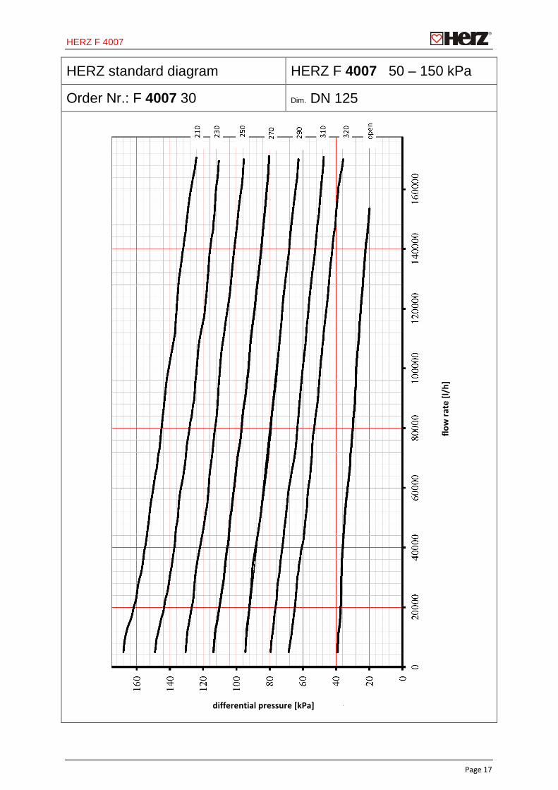
HERZ standard diagram HERZ F 4007 50 – 150 kPa
Order Nr.: F 4007 30 Dim. DN 125
flow
rate
[l/h
]
differential pressure [kPa]
HERZ F 4007
Page 18
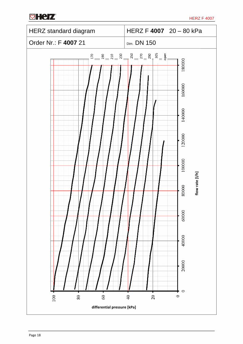
HERZ standard diagram HERZ F 4007 20 – 80 kPa
Order Nr.: F 4007 21 Dim. DN 150
flow
rate
[l/h
]
differential pressure [kPa]
HERZ F 4007
Page 19
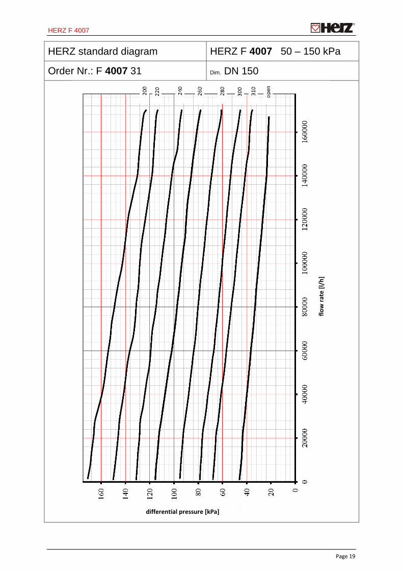
HERZ standard diagram HERZ F 4007 50 – 150 kPa
Order Nr.: F 4007 31 Dim. DN 150
flow
rate
[l/h
]
differential pressure [kPa]