Embed Size (px)
Citation preview

f-3 I- it( 'r SOLUTIONS 82A9617
Characterization Plan Whittaker Corporation
Waste and Slag Storage Area Reynolds Industrial Park Transfer, Pennsylvania
Revision 0
Authored By:
Reviewed Bq :
Approved By:
Approved By:
U. S. Nuclear Regulatory Commission Radioactive Materials License No. SMA-1018
Prepared by: EnergySolurions, LLC
Commercial Services Division 143 West Street
New Milford, CT 06776
k/- Y LAyL April 13,2007 Kevin Taylor, PE. CHP Date
&ril 13,2007 Gerard M. Tourney I Project Manager
Date
April 13. 2007 Kenneth M. Kaspcr, CIH, CHP RSO Date
- April 13_ 2007 Phillip' Malich . Operations Manager Date

Characterization Plan 82A9617 Whittaker Corporation Waste and Slag Storage Area Revision 0
REVISION LOG
Revision Number Affected Pages CRA Number Approval
Page 2 of 17

Characterization Plan 82A9617 Whittaker Corporation Waste and Slag Storage Area Revision 0
TABLE OF CONTENTS &
1 .O INTRODUCTION ...................................... ....................................................... 5
2.0 BACKGROUND ...................... ..................................................... 10 2.1 Site Description and His ..................................................... 10 2.2 Remedial Work Completed ................................................................... 10 2.3 Summary of Subsurface S a on GMI Propert?. ................................... 10
ADDITIONAL GMT PROPERTY CHARACTERIZATION.. ..................................... 10 3.1 Gamma Walkover Survey.. ..................................................... 10 3.2 Borehole 52 tnvestigakion . . ................................................................... 13 3.3 Borehole Investigation wit Logging ....................................... 3.4 Data Management ....................................................................................... I6 3.5 Scanning Equipme ..........................................................................
3.0
4.0 CHARACTERIZATION REPORT ..... .............................................................. 16 4. I Letter Report .................. ....................................................... I6 4.2 Discussion of Results.. ... ................................ 17
5.0 REFERENCES .......................... ...................................................... 17
FIGURE 1 FlGURE 2 FIGURE 3 FIGURE 4 FIGURE 5
TABLE 3- I
APPENDIX A
FIGURES
WHITTAKER SITE AND GREENVILLE METALS .................................. 6 DRILL LOCATIONS ADJACENT TO SECTIONS 2 & 4 .......................... 8 DRILL LOCATIONS ADJACENT TO SECTIONS 1 & 4 .......................... 9 WALK-OVER SURVEY AREA ................................................................ 12 SAMPLE LOCATIONS ADJACENT TO SECTION I ............................. 14
TABLE
ACTIVITY LEVELS OF CONCEXN ......................................................... 12
APPENDIX
SUMMARY OF BOREHOLE SURVEY DATA
Page 3 of 17

Characterization Plan 82A9617 Whittaker Corporation Waste and Slag Storage Area Revision 0
ABBREVIATIONS/ACRONYMS
2x2. Nal CPm DCGL Energy Solutions GMI GPS NRC pCi/g Whittaker
2-inch by 2-inch sodium iodide detector counts per minute Derived Concentration Guideline L e d EnergySoJutions, LLC Greenidle Metals, Inc. Global Positioning Satellite U.S. Nuclear Regulatoy Commission Picocuries per gram Whittaker Corporation
Page 4 of I7

Characterization Plan 82A9617 Whittaker Corporation Waste and Slag Storage Area Revision 0
1.0 INTRODUCTION
The Whittaker Site is located in the Reynolds Industrial Park in Transfer, Pennsylvania, approximately 3.5 miles south of the borough of Greenville. The Whittaker site and adjoining Greenville Metals, lnc. (GMI) property are shown in Figure 1. The site is an irregularly shaped parcel of land with a total area of approximately 6 acres located between the GMI properly at 99 Crestview Drive and the Shenango River.
The Whittaker Corporation, as well as prior owners of the site, used raw source material containing licensable quantities of thorium and uranium to process rare earth metals on site. The source materials consisted mainly of Brazilian and Canadian Pyrochlore. a mineral found in some granatic geologic formations. Manufactwing operations, which produced the thorium- and uranium-containing slag as a byproduct. commenced in 1966 and terminated in 1974. These slag byproducts were disposed of in areas within the boundaries of the present site. The rahological contaminants consist of natural thorium and uranium and their daughter products in approximate secular equilibrium. Analysis of slag materials also shows that uranium-238 exists in some materials in disequilibria with its decay daughters.
U.S. Nuclear Regulatory Commission (NRC) License No. SMA-1018 was issued on December 15. 1969, pursuant to I O CFR Part 40, and has been amended periodically since that time. The license authorized ihe possession and use of unsealed source material (natural thorium and natural uranium) contained in ores used for minerals processing and as a contaminant that was isolated by the processing of scrap metal. The NRC-licensed facility originally consisted of a plant and a slag waste storage area. In 1974, the Licensee ceased licensed operations and initiated decommissioning of plant equipment and buildings. Waste slag. raw materials. feed-metal scrap, and contaminated building materials that w-ere generated from the decontamination activities were placed in the slag storage area. The portion of the property housing the plant was released for unrestricted use in 1975, following the performance of a confirmatory survey by the NRC. An additional plant building was decommissioned in 1083 and released for unrestricted use in 1985.
The GMI facilily is an active facility that is not associated with the Licensee. GMI processes and refines scrap and other metals to produce metal alloys and conversion products. GMI does not utilize NRC-licensed radioactive material, and is separated from the Whittaker properly by metal fencing.
The Whittaker property is characterized by four sections according to topography and site use. Section 2 is in the center, bordered by Section 3 lo the north, the boundary fence with the GMI plant to the west, a ravine to !he south, and floodplain and the Shenango River to the east. Section 2 contained the highest-activity slag, most of which has now been excavated and disposed in accordance with the Licensee’s procedures that were approved by NRC in the license amendment dated June IO, 1999. There are no buildings remaining on the Whittaker properly with the exception of temporaq trailers supplied by the decommissioning contractor.
Page 5 of 17

82A9617 Characterization Plan ~
Whittaker Corporation Waste and Slag Storage Area Revision 0
FIGURE 1 WHITTAKER SITE AND GREENVILLE METALS
Page 6 of 17

Characterization Plan 82A9617 Whittaker Corporation Waste and Slag Storage Area Revision 0
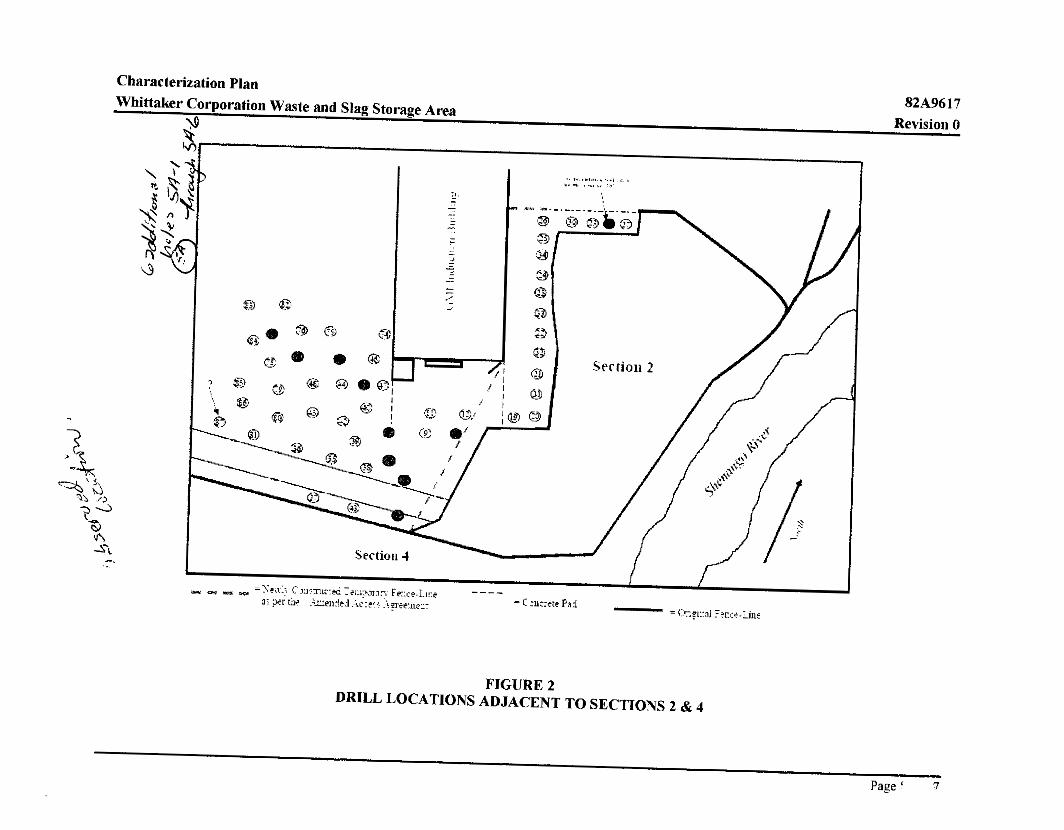
During routine remedial action support S I J I T ~ S buried radioactive slag was found to extend beyond the original Section 2 fence line. Radioactive subsurface slag was excavated and moved back onto Whittaker controlled property and prepared for shipping and disposal. In September and October of2006, sample boreholes were drilled outside the perimeter of Section 2 as part of an effort to determine if there was elevated subsurface activity outside the areas currently designated for remediation. The sample boreholes were investigated using a 2-inch by 2-inch sodium iodide (2x2 Nal) gamma scintillation probe to determine relative activity levels with depth. Seventy six boreholes were drilled and 1-minute count rates recorded at 2-foot intends. The drill locations are indicated in Figures 2 and 3 (drawings not to scale). This data indicated some areas of elevated subsurface activity on the GMI property adjacent to Whittaker site Sections 2 and 4. Those boreholes with indications of elevated activity are shown in red circles and other locations are shown as green circles. These results, while not definitive. indicate that additional sampling will be required to define the extent of elevated activity
The purpose of this Characterization Plan is to direct additional characterization such that decisions can be made for the path forward to terminate the facililv license. The path forward may include activities such as additional remediation, development or derived concentration guideline levels (DCGL) for subsurface activity, preparation of a dose assessment for leaving subsurface materials in place, obtaining NRC concurrence for license termination, etc.
Page 7of I7

Characterization Plan 82A9611 Whittaker Corporation Waste and Slag Storage Area Revision 0
Q 0 0 ....... ......................................
.... Srcctlm 4 ...
FIGURE 3 DRILL LOCATIONS ADJACENT TO SECTIONS 1 & 4
Page9of 17

Characterization Plan 82A9617 Whittaker Corporation Waste and Slag Storage Area Revision 0
2.0 BACKGROUND
2.1
2.2
2.3
Site Description and Historical Uses
Since contaminated slag was found outside of the Section 2, and indications of subsurface contamination was found when sample boreholes were drilled outside the perimeter of Section 2 as part of an effort to define residual subsurface activity in the area, the Whittaker Corporation has requested ihat the radiological conditions at the Site be evaluated further by conducting an additional characterization such that decisions can be made on the path fonvard to address radioactive materials located on GMI propem.
Once the additional characterization is performed the results will be evaluated with regard to contemporary regulations and the development of an acceptable and cost effective approach to addressing radioactive materials on GMI property and license termination.
Remedial Work Completed
The remediation of Sections 1, 2, and 4 of the Whittaker site are essentially complete except for waste segregation and shipping and performance of the final survey. There is still waste staged on the pad in Section 3 to be shipped.
Summary of Subsurface Survey Data on GMI Propertj
The borehole monitoring data for all holes indicates an average reading of 5344 cpm with a maximum reading of 440,400 cpm and a minimum reading of 2,770 cpm (two readings of about 500 cpm were tossed out as outliers.) The monitoring data is presented in Appendix A. There were 5 holes where the average reading exceeded 7,000 cpm and 1 I holes where at least one reading exceeded 7:000 cpm. Monitoring of activity in boreholes in this area is problematic because of the potential for radon collection in the boreholes and the possibility that the Geoprobe type sampler will push slag material out of the way of the sampling head. The 7,000 cpm value is not a definitive value to indicate contamination in excess of DCGLs but it was used as a sorting tool to indicate areas of potential elevated activity.
3.0 ADDITIONAL GMI PROPERTY CHARACTEREATION
3.1 Gamma Walkover Survey
A gamma radiation walkover survey using a 2x2 Nal gamma scintillation detector will be conducted in the areas where prior subsurface data was obtained and in the areas where additional subsurface data is needed. Preferably, the 2x2 Nal detector will be coupled to a global positioning system (GPS) that will record the location and gamma radiation count rate once eveq 2 seconds during the walkover survey. However, in the event that the GPS/detector system is
Page I O of 17

Characterization Plan 82A9611 Whittaker Corporation Waste and Slag Storage Area Revision 0
unavailable, a second technician will follow along and mark elevated areas (count rates above the investigation level provided in Table 3-1) with pin flags, stakes, or similar marking materials. Figure 4 shows the approximate area of initial walk- over survey area extending northward from the paved drive leading to the south entrance of the Induction Building. The initial survey area should extend 200 feet northwest from the paved road and 150 feet southwest of the Induction Building. The perimeter of investigation area &ill increase beyond the area shown in Figure 4 at the discretion of the Site Supervisor if wide-spread surface activity is identified.
A survey technician will walkover the Site at a rate of about 0 . 5 meter per second while moving the detector in a serpentine pattern about 1 meter wide with the detector kept close to the ground, -6 cm or 2.5-inches in accordance with the Multi-Agency Radiation Survey and Site Investigation Manual (U.1RsVM) (Reference 5.1). Following the completion of the gamma walkover survey: the GPS location and gamma count rate data will be downloaded and maps generated showing survey data by location.
The field team will use only instrunients operated and calibrated in accordance with EnergySolutiom General Radiological Survey and Air Sampling Procedure and Calibrafion and Maintenance of Survey Instruments Procedure (References 5.2 and 5.3).
Logged data will be presented on survey maps such that data above an investigation level count rate representative of an investigation level of 3.5 picocuries per gram (pCi/g) thorium-232 in equilibrium with its decay daughters (Th-232+D) and the DCGL of 7.0 pCi/g Th-232+D in accordance with Scientech, LLC Document No. 82A9534, Dose Assessment in Support uf Establishing Derived Concentration Guideline Levels for the Whit faker Decommissioning Site (ReTerence 5.4) are clearly identifiable, The estimated net count rates representative of these values are provided in Table 3-1
Site features such as buildings, roads. creeks. and fence lines will also be marked so that they can be placed on survey niaps.
Areas with surface activity above the DCGL-equivalent net gamma count rate will likely be excavated. The general are@) encompassing these areas of elmated surface activity will be designated as area(s) “impacted with surrace activity.’’ This Characterization Plan does not address further subsurface characterization in these areas.
Page 1 I of 17

Characterization Plan 82A9617 Whittaker Corporation Waste and Slag Storage .4rea Revision 0
Bench Mark
Investigation Level DCGL
N
METALS PROPERTY
Th-232+D Modeled Net Expected Net Activity Exposure Count Rate (pCi/g) Rate (uR/hr)'
3.5 6.4 5,300 7.0 12.7 10,500
FIGURE 4 WALK-OVER SURVEY AREA
Page 12 of I7

Characterization Plan 82A9617 Whittaker Corporation Waste and Slag Storage .4rea Revision 0
3.2 Borehole 52 Investigation
As shown in Appendix A, Borehole No. 52 had elevated activity indicated at a depth of 14-feet below the ground surface (49,060 cpm). There were no other indications of elevated activity close to this borehole. The existing boreholes to the north (No. 51) and south (No. 53) did not indicate elevated activity and those directions will not be investigated any further at this time.
It is possible that the count rate data was entered incorrectly. Once back on site, EnergySvlutions w-ill check the original survey records to veri% the measurement. EnergySolutions may also resurvey the bole if it is assessable (a PVC casing should have been placed in the hole to allow additional surveys as needed). If the data point can he verified, additional borings will be placed around Borehole No. 52 as shown in Figure 5 using the methodology described in Section 3.3.
Page 13 or 17

Characterization Plan 82A9611 Whittaker Corporation Waste and Slag Storage 4rea Revision 0
0 69: 1 1 i
FIGURE 5 SAMPLE LOCATIONS ADJACENT TO SECTION 1
Page 14 of 17

Characterization Plan 82A9617 Whittaker Corporation Waste and Slag Storage .4rea Revision 0
3.3 Borehole Investigation with Gamma Logging
Prior to drilling west of the Greenville Metals Induction Building, a utility survey shall be conducted to identify buried pipes and electrical lines.
Additional characterization of areas with measurable surface activity indicating the presence of radioactive materials above the Th-232+D DCGL is not described in this Plan. This section describes the borehole investigation outside the area(s) designated as “impacted with surface activity” identified following the survey described in Section 3. I .
Boreholes will be spaced on a square grid pattern with the spacing determined by the size of the investigation area and the number of boreholes allotted by the project objectives. The Site Supervisor will direct the drillers to the locations of the boreholes. The locations approved by the project health physicist will be identified on a map prior to drilling.
A hollow stem auger of at least 6 inches in diameter will be used to advance boreholes to a minimum depth of 22 feet. All pieces of rock or slag brought to the surface should be surveyed for elevated radioactivity using a 2x2 Nal detector. Additionally the soil removed from the hole should be scanned with the detector.
A hose attached to the discharge of an air sampler (or equivalent air supply) will be inserted in the hole to purge radon. Following the air purge a 2x2 NaI detector will be lowered down each hole and the count rate recorded in 2 foot intervals. The detector should be wrapped in plastic to prevent it from becoming contaminated or damaged by groundwater that may be encountered in some holes. The count rate will be recorded hy taking a one-minute static count.
No soil samples will be collected from the bore holes
If the auger cannot be advanced to a depth of at least 20 feet, the hole location will be abandoned and another attempt will be made within 1 meter from the previous point.
If the proper equipment is available, the GPS position of each borehole location (old and new) will be recorded.
Five boreholes from the boreholes presented in Appendix A that do not indicate the presence of any subsurface activiv will be used as a set of background boreholes. New measurements will be made to determine the average background count rate and the standard deviation of the background data. To best represent the background near the area of interest, none of the background holes should be from the holes around the perimeter of Section I or Section 3.
The holes will be purged of radon as indicated above.

Characterization Plan 82A9617 Whittaker Corporation Waste and Slag Storage .4rea Revision 0
3.4 Data Management
The survey data generated from this supplemental characterization effort will be electronically recorded. As a minimum, the survey data will be downloaded at the end of every day that data is collected. In addition the download files on the computer will be backed up on removable storage media at the end of every day that new data is downloaded. Once the count rate data is collected, it will be combined into a database that will allow the data to be processed and analyzed.
The detector position and gross gamma count rates recorded by the GPS system during the walkover survey will be plotted on a base map to show the intensity of the gamma radiation at each individual logged location.
All data will be reviewed first in the field by the on-site supervising radiological engineer or health physicist and later reviewed by the project health physicist.
A field logbook will be maintained by the field team leader. This logbook will include daily observations; notes on the borehole survey effort including physical descriptions of materials removed from the boreholes.
3.5 Scanning Equipment
The Ludlum Model 44-9 "pancake" type Geiger-Mueller detector connected to a Ludlum Model 2220 rate meter or equivalent will be used as a contamination monitor to "frisk" equipment and personnel in accordance with general site operating procedures.
4.0 CHARACTERIZATION REPORT
4.1 Letter Report
The supplemental characterization data will be summarized and presented in a Letter Report. The Report will present a three-dimensional portrayal of subsurface radioactive materials.
Each downhole measurement that is greater than the mean of the background holes plus two standard deviations will be assigned a discrete volume of radioactive materials of assumed activity. Depending on the spacing of the boreholes, a volume of below surface material will be assigned an activity equal to the average activity of slag and other debris material shipped off-site for disposal and background soil with a 140-1 volume mix. The average activities, as used for shipping are:
Th-232+D 93 pCi/g U-238+D 2.0 pCi/g
Page 16 of 17

Characterization Plan 82A9617 Whittaker Corporation Waste and Slag Storage Area Revision 0
The volume of the subsurface "puck" will be calculated with a two foot thickness (the distance between downhole measurements) and a diameter equal to the distance between boreholes.
4.2 Discussion of Results
The report will discuss the results relative to the potential dose to a population exposed to the buried materials in the area of interest. RESRAD model runs utiliclng site-specific parameters and the conceptual source term consistins of subsurface "pucks" of radioactive materials at locations determined by the downhole measurements.
5.0 REFERENCES
5.1
5.2
5.3
5.4
5.5
5.6
U.S. Nuclear Regulator): Commission. Multi-Agency Radiarion Survey and Sire Investigation Manual (MARSSIM). NUREG-1575 Revision 1, August 2000.
EnergySolutions, LLC. General Radiological Survey and Air Sampling Procedure. Document No. 82A8008, Revision 8. March 2006.
EnergySolutions. LLC. Calibration and Maintenance qf Surve-v Instruments Procedure. Document No. 82A8034, Revision 7. March 2006.
Scientech, LLC. 2004. Dose Assessment in Support of E,ytablishing Derived Concenlration Guideline Levels ,fir the Whittaker Decommissioning Site. Document No. 82A9534, Revision 1. August 2004.
MicroShield. Version 7.00. Grove Software, Inc. Copyright CG 1995-2005
U.S. Nuclear Regulator): Commission. Minimum Detectable Concentrarions Wrth l:vpical Radiation Survey Instruments for Various Contaminants and Field Conditions. NUREG- 1507. June 1998.
Page 170f I7

Characterization Plan 82A9617 Whittaker Corporation Waste and Slag Storage Area Revision 0
APPENDIX A
SUMMARY OF BOREHOLE SURVEY DATA

Characterization Plan 82A9617 Whittaker Corporation Waste and Slag Storage Awa Revision 0
Whittaker Bore Hole Monitoring Data Readings laken with a 2'12" Nil1 probe wilh a 40' cable Realis in gross cooun15 Per minule (gcprn)
AVO: 5,171 4,700 STDEV: 469 547
MAX: 6,180 5.570 MIN: 4,580 3.930
AVG*STDEV 5,640 5,247 Ekv of MAX:
Averaae Readlna (Z.2Vl: Roadlng Std. Dev. (Z-20*):
Marlmum Reading (2'-20'): Minimum Reading (2'-2V):
3,709 4,259 4,060 4,194 5,366 4,817 4,794 4.523 5,888 4.813 4.057 4,127 4.727 21.969 656 757 545 4,635 616 567 710 522 49.400
4,500 4,920 4.990 4,740 5,950 5,520 5.380 5,370 18.990 5,630 6.140 4.890 5,450 162,000
4,270 4.688 4,751 4.583 5,707 5,473 5,551 5,068 10.523 5,429 1.644 4.637 5,249 71,369 14 12
389 341 561 429 691
2.940 3,500 3.090 3.570 4,810 3.650 3.500 3,560 3,580 3.790 2.830 3.040 3,870 3.830
5,944 19,010
440.400 2,770

Characterization Plan 82A9611 Revision 0 Whittaker Corporation Waste and Slag Storage Area
Whlttaher Bore Hole Monitoring Data Readings taken with B 2 x 2 ' Nal probe With a 40' cable R ~ L u I I s In gross counts p n minute (gcprn)
AVO: 4,815 4,885 4,866 4,883 4,370 5.085 4.152 4.656 4,652 5.190 5,028 4,931 4,410 4.249 4.366 4,814 STDEV: j?6 336 247 571 554 2,491 4aa 419 325 669 970 352 780 738 722 924
MAX 5,110 5,680 5,190 5,560 5,180 11.500 5.340 5,560 5,050 6.100 7.460 5.510 5.280 5,110 5,420 5,600 MIN 4,460 4,550 4,330 3,870 3.620 3.290 3.670 4,240 4.120 4.250 4.070 4,320 3.170 3.130 3.000 2.780
AVGtSTOEV 4.991 5,222 5.113 5,454 4.924 7,576 5.240 5.275 4,977 5.759 6.W4 5,283 5.200 4,987 5.088 5,737 Elev of MAX: 12

Characterization Plan 82A9617 Whittaker Corporation Waste and Slag Storage Area Revision 0
Whittaker Sore Hole Monitoring Data Readings laken wilh a 2'rT Nal pmbe wilt) a 40' cable RCSUIIS in gross counts permhue (gcpml
AVG: 4.820 4.755 4.636 9.015 4.515 4,447 4.185 4.308 4.466 4.392 4.573 4.723 5.169 4,451 5,OW 4.232 789 777 434 1.034 567 641 665 763 425 684 2.145 1.068
MAX 5.450 5.260 5.150 49.050 5.560 6,350 4.720 5.650 5.200 5.000 5,310 6,330 5,680 5.150 10,230 6,020 MIN: 3,750 4,450 3,550 4,100 3.260 3,340 3.350 2.910 3,390 3,150 3,050 3,720 4,300 3,240 2,770 3,230
AVGISTDEV: 5,383 5.028 5.137 23,086 5.304 5,224 0.619 5,342 5,033 5.033 5.237 5.506 5,594 5.135 7,154 5,303 Eiev of MAX
STDEV: 563 273 501 14.071
14 6
Page A3 c

Characterization Plan 82A9617 Whittaker Corporation Waste and Slag Storage Area Revision 0
4,138 5,197 4,309 AVO: 3.844 3,962 4,942 4,104 3.943 4.175 4.074 4.018 4,020 4,545 3.759 STDEV: 334 348 545 353 530 285 317 407 424 924 255 563 905 590 MAX: 4,340 4.490 5.480 4.460 4,730 4,430 4,470 4,440 4,420 5.910 4,200 5,190 6.360 5.250 MIN: 3,330 3,440 3,570 3,220 3,050 3.600 3,580 3,130 3,100 3.230 3,350 3.510 3,930 3.540
AVGcSTDEY: 4,178 4.310 5.487 4,457 4,473 4.460 4.391 4,425 4,444 5,468 4.014 0 4,701 6.102 4.899 Elev of MAX:
Page A4 c

Characterization Plan 82A9617
Revision 0 Whittaker Corporation Waste and Slag Storage Area
AYG: 3,898 5.303 5.231 5.212 5 , 3 0 2 5,006 4,098 3,914 4477 1.177 1,398 5.806 59,763 27.339 STDEV: 289 479 450 609 519 903 409 415 1,293 607 7,929 4,859 138,003 65.969
MAX: 4.220 5.980 5.680 6,070 5,880 5.850 4,610 4,500 7,910 5.520 29.500 19,570 UO.400 215.100 MIN 3.230 4.500 4.570 4,050 4 , 1 5 0 3.400 3.500 3.150 3.220 3.280 3,340 3,870 3,850 1.560
AVGtSTDEV: 4,187 5,707 5,681 5,021 5,701 5,989 4.507 4.334 5,770 4.784 15,327 10.745 187,766 93.908 €lev of MAX: 2 6 8 12 16
Page A5 c
,J J