Embed Size (px)
Citation preview
EyeLink® User Manual
For EyeLink models:
EyeLink 1000 EyeLink 2000
EyeLink Remote
Version 1.3.0
Copyright © 2005-2007, SR Research Ltd. EyeLink is a registered trademark of SR Research Ltd., Mississauga, Ontario, Canada.
EyeLink 1000 User Manual version (9/13/2007) © 2005-2007 SR Research Ltd. ii
Table of Contents
1. Introduction ........................................................................................................... 1 1.1 Supporting Documents......................................................................... 2 1.2 EyeLink 1000 System Configuration ..................................................... 2
1.2.1 Host PC ......................................................................................................... 3 1.2.2 Display PC..................................................................................................... 4 1.2.3 EyeLink 1000 Hardware Configurations ........................................................ 4
1.3 System Specifications........................................................................... 6 1.3.1 Operational / Functional Specifications ......................................................... 6
1.4 Physical Specifications ......................................................................... 7 2. EyeLink 1000 Tracker Application Operation ..................................................... 9
2.1 Starting the Host Tracker ..................................................................... 9 2.2 Modes of Operation .............................................................................. 9 2.3 EyeLink 1000 Host PC Navigation....................................................... 10
2.3.1 Offline Screen.............................................................................................. 11 2.3.2 Set Options Screen ..................................................................................... 12 2.3.3 Camera Setup Screen ................................................................................. 19 2.3.4 Calibrate Screen.......................................................................................... 24 2.3.5 Validate Screen ........................................................................................... 27 2.3.6 Drift Correct/Drift Check Screen.................................................................. 29 2.3.7 Output Screen ............................................................................................. 30 2.3.8 Record Screen............................................................................................. 32
2.4 Status Panel....................................................................................... 39 2.5 Mouse Simulation Mode ..................................................................... 40 2.6 Configuration Files and Experiment Directories .................................. 40
3. An EyeLink 1000 Tutorial: Running an Experiment ......................................... 43 3.1 The Camera Setup Screen .................................................................. 44 3.2 Participant Setup ............................................................................... 45
3.2.1 Tower Mount Participant Setup, Monocular ................................................ 45 3.2.2 Desktop Mount (Level) Participant Setup, Monocular ................................. 50 3.2.3 Desktop Mount (Angled) Participant Setup, Binocular ................................ 53 3.2.4 EyeLink Remote Participant Setup.............................................................. 58
EyeLink 1000 User Manual version (9/13/2007) © 2005-2007 SR Research Ltd. iii
3.3 Setting Pupil Threshold ...................................................................... 65 3.4 Setting Corneal Reflection (CR) ........................................................... 67 3.5 Search Limits..................................................................................... 68 3.6 Pupil Tracking Algorithm.................................................................... 69 3.7 Calibration......................................................................................... 69 3.8 Validation .......................................................................................... 73 3.9 Improving Calibration Quality ............................................................ 75 3.10 Recording Gaze Position .................................................................. 75 3.11 Drift Correction / Drift Checking ..................................................... 76 3.12 Exiting EyeLink 1000 ...................................................................... 78 3.13 EyeLink 1000 Setup Summary ........................................................ 78 3.14 Experiment Practice ........................................................................ 79 3.15 Next Steps: Other Sample Experiments............................................ 79
4. Data Files ............................................................................................................. 83 4.1 File Contents...................................................................................... 83 4.2 Recording EDF Files........................................................................... 84
4.2.1 Recording from the EyeLink 1000 Host PC................................................. 84 4.2.2 Recording from the EyeLink API or SR Research Experiment Builder ....... 84
4.3 The EyeLink On-Line Parser ............................................................... 84 4.3.1 Parser Operation ......................................................................................... 84 4.3.2 Parser Limitations........................................................................................ 85 4.3.3 EyeLink Parser Configuration...................................................................... 85 4.3.4 Parser Data Type ........................................................................................ 86 4.3.5 Saccadic Thresholds ................................................................................... 86 4.3.6 Pursuit Thresholds ...................................................................................... 87 4.3.7 Fixation Updates ......................................................................................... 87 4.3.8 Other Parameters ........................................................................................ 88 4.3.9 Sample Configurations ................................................................................ 88 4.3.10 Reparsing EyeLink Data Files.................................................................. 89
4.4 File Data Types .................................................................................. 90 4.4.1 Samples....................................................................................................... 90 4.4.2 Position Data ............................................................................................... 90 4.4.3 Pupil Size Data............................................................................................ 93 4.4.4 Button Data.................................................................................................. 93
EyeLink 1000 User Manual version (9/13/2007) © 2005-2007 SR Research Ltd. iv
4.5 Events ............................................................................................... 94 4.5.1 Messages .................................................................................................... 94 4.5.2 Buttons ........................................................................................................ 94 4.5.3 Eye Movement Events................................................................................. 95
4.6 Setting File Contents .......................................................................... 99 4.6.1 Sample Data................................................................................................ 99 4.6.2 Event Data................................................................................................... 99 4.6.3 Event Types .............................................................................................. 100
4.7 EDF File Utilities .............................................................................. 101 4.8 Using ASC Files................................................................................ 101 4.9 The ASC File Format ........................................................................ 102
4.9.1 ASC File Structure..................................................................................... 102 4.9.2 Sample Line Format .................................................................................. 103 4.9.3 Event Line Formats ................................................................................... 106 4.9.4 Data-Specification Lines............................................................................ 108
4.10 Processing ASC Files ..................................................................... 109 5. System Care....................................................................................................... 111
5.1 Maintenance .................................................................................... 111 5.2 Storage and Transportation .............................................................. 111
6. Important Information ....................................................................................... 112 6.1 Safety .............................................................................................. 112
6.1.1 Eye Illumination Safety .............................................................................. 112 6.2 Servicing Information ....................................................................... 114
6.2.1 Non-Serviceable Components:.................................................................. 114 6.2.2 Illuminator Replacement:........................................................................... 114 6.2.3 Cables and Lenses:................................................................................... 115 6.2.4 Power Supply Replacement: ..................................................................... 116
6.3 Limited Hardware Warranty ............................................................. 117 6.4 Limited Software Warranty ............................................................... 118 6.5 Copyrights / Trademarks ................................................................. 118
7. Appendix A: Using the EyeLink 1000 Analog and Digital Output Card........ 119 7.1 Analog Data Types............................................................................ 119 7.2 Analog Data Quality ......................................................................... 120 7.3 Setting up the EyeLink 1000 Analog Card......................................... 120
EyeLink 1000 User Manual version (9/13/2007) © 2005-2007 SR Research Ltd. v
7.3.1 Installing Analog Output Hardware............................................................ 120 7.3.2 Connections to Analog Card...................................................................... 121 7.3.3 Noise and Filtering .................................................................................... 121
7.4 Digital Inputs and Outputs............................................................... 121 7.4.1 Analog Data Output Assignments ............................................................. 122 7.4.2 Analog Data Types and Ranges................................................................ 123 7.4.3 Scaling of Analog Position Data ................................................................ 123
7.5 Pupil Size Data................................................................................. 124 7.6 Timebase and Data Strobe................................................................ 124
7.6.1 Strobe Data Input ...................................................................................... 125 7.6.2 Oversampling and Toggle Strobe.............................................................. 125

EyeLink 1000 User Manual version (9/13/2007) © 2005-2007 SR Research Ltd. vi
List of Figures
Figure 1-1: Typical EyeLink 1000 Configuration (Tower Mount) ........................ 2 Figure 1-2. EyeLink 1000 Desktop Mount with Camera Level and Angled ......... 5 Figure 1-3. EyeLink 1000 Tower Mount ........................................................... 5 Figure 2-1: EyeLink 1000 Host PC Application Overview .............................. 10 Figure 2-2 Offline Screen ............................................................................... 11 Figure 2-3 Set Options Screen ....................................................................... 13 Figure 2-4 Camera Setup Screen ................................................................... 19 Figure 2-5 Calibrate Screen ........................................................................... 25 Figure 2-6 Validate Screen............................................................................. 27 Figure 2-7. Drift Correct/Drift Check Screen.................................................. 29 Figure 2-8 EyeLink 1000 Output Screen ........................................................ 31 Figure 2-9 Record Screen (Gaze Cursor View)................................................. 33 Figure 2-10 Record Screen (Plot View) ............................................................ 34 Figure 2-11. Gain/Offset Adjustment in the Plot View .................................... 39 Figure 2-12 EyeLink 1000 Status Panel ......................................................... 39 Figure 3-1: Example Camera Setup Screen (Tower Mount). ............................ 44 Figure 3-2: Parts of the EyeLink 1000 Tower Mount..................................... 47 Figure 3-3: Adjust the Chair Height for EyeLink 1000 Tower Mount ............. 48 Figure 3-4: Focusing the Eye Camera for EyeLink 1000 Tower Mount .......... 50 Figure 3-5: Parts of the EyeLink 1000 Desktop Mount ................................. 51 Figure 3-6. Camera Setup with Subjects Wearing Glasses (the EyeLink 1000
Monocular Mount). .................................................................................. 52 Figure 3-7: Focusing the Desktop Mount Camera......................................... 53 Figure 3-8: Position and Angle of the Camera for EyeLink 1000 Desktop
Monocular vs. Binocular Mount ............................................................... 55 Figure 3-9. Camera Setup Screen Desktop Mount (Angled), Binocular Recording56 Figure 3-10. Camera Setup with Subjects Wearing Glasses (Desktop Mount –
Camera Angled). ...................................................................................... 57 Figure 3-11: Camera Setup Screen with the EyeLink Remote ....................... 60 Figure 3-12. Target Position for EyeLink Remote ............................................ 62 Figure 3-13. Pupil and CR Thresholds and Bias Values .................................. 63 Figure 3-14. Pupil Size Information from the Status Panel.............................. 65

EyeLink 1000 User Manual version (9/13/2007) © 2005-2007 SR Research Ltd. vii
Figure 3-15. Target and Eye Positions in the Thumbnail Camera Images ........ 65 Figure 3-16: Symptoms of Poor Pupil Threshold........................................... 66 Figure 3-17: Corner Effects Seen with Head Rotation ................................... 67 Figure 3-18: Corneal Reflection...................................................................... 68 Figure 3-19. Calibration Grid......................................................................... 71 Figure 3-20. Performing On-line Drift Correction with Mouse Click................. 77
Read instructions before use.
US
C Certified
Entela Safety Mark: Compliance of this product with UL 60950 3rd Edition, CSA C22.2 No 60950-00-CAN/CSA is certified by Entela, an independent testing body.
CLASS 1 LED DEVICE IEC 60825-1 (Ed. 1.2:2001)
EyeLink 1000 User Manual version (9/13/2007) © 2005-2007 SR Research Ltd. viii
CAUTION: Use of controls or adjustments or performance of procedures other than those specified herein may result in hazardous radiation exposure.
FCC Statement: NOTE: This equipment has been tested and found to comply with the limits for a Class A digital device, pursuant to part 15 of the FCC Rules. These limits are designed to provide reasonable protection against harmful interference when the equipment is operated in a commercial environment. This equipment generates, uses, and can radiate radio frequency energy and, if not installed and used in accordance with the instruction manual, may cause harmful interference to radio communications. Operation of this equipment in a residential area is likely to cause harmful interference in which case the user will be required to correct the interference at the users’ expense. FCC Notice: This device complies with Part 15 of the FCC rules. Operation is subject to the following two conditions: (1) this device must not cause harmful interference and (2) this device must accept any interference received, including interference that may cause undesired operation. CISPR WARNING: This is a Class A product. In domestic environments this product may cause radio interference in which case the user may be required to take adequate measures. WARNING: Changes or modifications not expressly approved by SR Research Ltd. could void the user’s warranty and authority to operate the equipment. This includes modification of cables, removal of ferrite chokes on cables, or opening cameras or connectors: WARNING: Opening or modifying cameras and connector will void the warranty and may affect safety compliance of the system. No user-serviceable parts inside—contact SR Research for all repairs.
CONTACT ADDRESS SR Research Ltd. 5516 Main St., Osgoode, Ontario, Canada K0A 2W0 Fax: 613-482-4866 Phone: 613-826-2958 Toll Free Phone: 1-866-821-0731 (North America Only) http://www.sr-research.com/
EyeLink 1000 User Manual version (9/13/2007) © 2005-2007 SR Research Ltd. 1
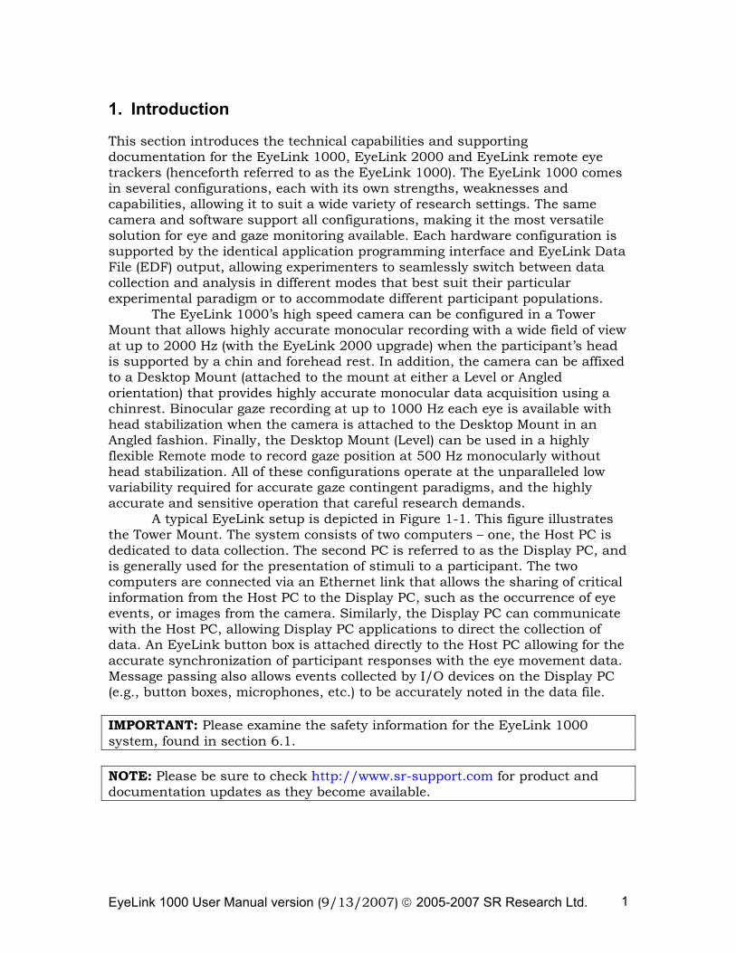
1. Introduction
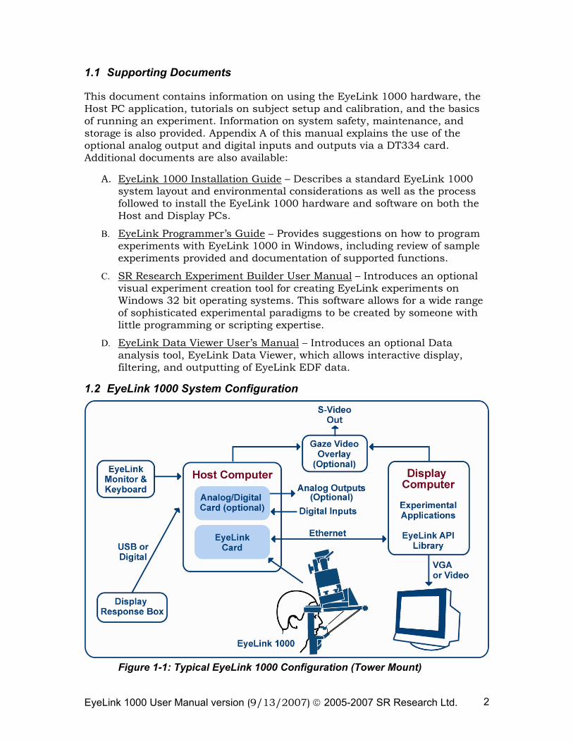
This section introduces the technical capabilities and supporting documentation for the EyeLink 1000, EyeLink 2000 and EyeLink remote eye trackers (henceforth referred to as the EyeLink 1000). The EyeLink 1000 comes in several configurations, each with its own strengths, weaknesses and capabilities, allowing it to suit a wide variety of research settings. The same camera and software support all configurations, making it the most versatile solution for eye and gaze monitoring available. Each hardware configuration is supported by the identical application programming interface and EyeLink Data File (EDF) output, allowing experimenters to seamlessly switch between data collection and analysis in different modes that best suit their particular experimental paradigm or to accommodate different participant populations. The EyeLink 1000’s high speed camera can be configured in a Tower Mount that allows highly accurate monocular recording with a wide field of view at up to 2000 Hz (with the EyeLink 2000 upgrade) when the participant’s head is supported by a chin and forehead rest. In addition, the camera can be affixed to a Desktop Mount (attached to the mount at either a Level or Angled orientation) that provides highly accurate monocular data acquisition using a chinrest. Binocular gaze recording at up to 1000 Hz each eye is available with head stabilization when the camera is attached to the Desktop Mount in an Angled fashion. Finally, the Desktop Mount (Level) can be used in a highly flexible Remote mode to record gaze position at 500 Hz monocularly without head stabilization. All of these configurations operate at the unparalleled low variability required for accurate gaze contingent paradigms, and the highly accurate and sensitive operation that careful research demands. A typical EyeLink setup is depicted in Figure 1-1. This figure illustrates the Tower Mount. The system consists of two computers – one, the Host PC is dedicated to data collection. The second PC is referred to as the Display PC, and is generally used for the presentation of stimuli to a participant. The two computers are connected via an Ethernet link that allows the sharing of critical information from the Host PC to the Display PC, such as the occurrence of eye events, or images from the camera. Similarly, the Display PC can communicate with the Host PC, allowing Display PC applications to direct the collection of data. An EyeLink button box is attached directly to the Host PC allowing for the accurate synchronization of participant responses with the eye movement data. Message passing also allows events collected by I/O devices on the Display PC (e.g., button boxes, microphones, etc.) to be accurately noted in the data file. IMPORTANT: Please examine the safety information for the EyeLink 1000 system, found in section 6.1. NOTE: Please be sure to check http://www.sr-support.com for product and documentation updates as they become available.
EyeLink 1000 User Manual version (9/13/2007) © 2005-2007 SR Research Ltd. 2
1.1 Supporting Documents
This document contains information on using the EyeLink 1000 hardware, the Host PC application, tutorials on subject setup and calibration, and the basics of running an experiment. Information on system safety, maintenance, and storage is also provided. Appendix A of this manual explains the use of the optional analog output and digital inputs and outputs via a DT334 card. Additional documents are also available:
A. EyeLink 1000 Installation Guide – Describes a standard EyeLink 1000 system layout and environmental considerations as well as the process followed to install the EyeLink 1000 hardware and software on both the Host and Display PCs.
B. EyeLink Programmer’s Guide – Provides suggestions on how to program experiments with EyeLink 1000 in Windows, including review of sample experiments provided and documentation of supported functions.
C. SR Research Experiment Builder User Manual – Introduces an optional visual experiment creation tool for creating EyeLink experiments on Windows 32 bit operating systems. This software allows for a wide range of sophisticated experimental paradigms to be created by someone with little programming or scripting expertise.
D. EyeLink Data Viewer User’s Manual – Introduces an optional Data analysis tool, EyeLink Data Viewer, which allows interactive display, filtering, and outputting of EyeLink EDF data.
1.2 EyeLink 1000 System Configuration
Figure 1-1: Typical EyeLink 1000 Configuration (Tower Mount)
EyeLink 1000 User Manual version (9/13/2007) © 2005-2007 SR Research Ltd. 3
1.2.1 Host PC
The EyeLink 1000 Host PC performs real-time eye tracking at 250, 500, 1000, or 20001 samples per second with no loss of spatial resolution, while also computing true gaze position on the display viewed by the subject. On-line detection analysis of eye-motion events such as saccades and fixations is performed. These events can be stored in a data file on the Host PC, sent through the Ethernet link to the Display PC with a minimal delay, or output as analog signals (if the analog/digital I/O card is installed). From the Host PC, the operator performs subject setup, monitors performance, and can control applications running on a Display PC. The Host PC has these key attributes:
• Hosts the EyeLink 1000 high-speed eye tracking card, optional analog output/digital input card.
• Uses a timing-sensitive operating system allowing low variability in EyeLink 1000 Host PC application response.
• The Host PC can be used for other purposes when not tracking eye movements. Other operating systems (such as Windows XP) can easily co-exist if the provided disk partitioning utility is used.
• Functions either as standalone tracker or connected to a Display PC through 10/100BASE-T Ethernet cable.
• In standalone configuration, data can be directed through optional analog output card and/or digitally stored on the hard disk.
• Response box or game pad connected by a USB port for highly accurate event recording synchronized with eye movement data.
• EyeLink 1000 software integrates all needed eye tracking functionality, including subject setup, calibration, real-time data through an Ethernet link or optional analog output card, and writing of data to hard disk.
• Remote configuration of the Host PC software is possible via commands sent over the Ethernet link.
• Real-time feedback of eye data is available on the Host PC during calibration or recording, allowing other network devices to be devoted to accurate stimulus delivery.
1 Availability of some sampling rates depends on the mount type and system version.
EyeLink 1000 User Manual version (9/13/2007) © 2005-2007 SR Research Ltd. 4
1.2.2 Display PC
The EyeLink 1000 Display PC administers eye tracker calibration , directs data collection, and presents stimuli during experiments. On-line eye and gaze position can be received from the EyeLink Host PC via the Ethernet link making gaze-contingent paradigms possible. The user can acquire the optional SR Research Experiment Builder to assist them in creating sophisticated EyeLink experiments on 32-bit Windows 2000 or XP.
For users who wish to program their own experiments, a wide range of programming options exist for assisting in automated data acquisition on the Display PC. A C programming API with example code exists for Windows, MacOS 9, Mac OS X, Linux, DOS and other operating systems. Additionally, there are methods available to use the EyeLink with several experiment delivery packages such as MATLAB (PC and MacOS via the Psychophysics Toolbox), Presentation, and E-Prime. Plus, other languages are supported as well, such as Python. For full details and links to downloadable resources, visit and join the SR Research support forums at
http://www.sr-support.com .
The Display PC has the following key attributes:
• Runs experiment application software for control of the EyeLink 1000 tracker and stimulus presentation using EyeLink programming API or SR Research Experiment Builder, allowing development of countless experimental paradigms.
• Display Applications can configure and control the EyeLink tracker, and have access to real-time data including gaze position, response box button presses, and keyboard, with minimal delay and low variability in timing.
• Applications only need to support stimulus generation and control of the experiment sequence. Relying on the Host PC for data acquisition and registering responses makes millisecond-accurate timing possible, even under Windows.
• Data file viewing and conversion tools such as EyeLink Data Viewer and EyeLink EDF2ASC converter assist researchers in deep analysis of the data obtained.
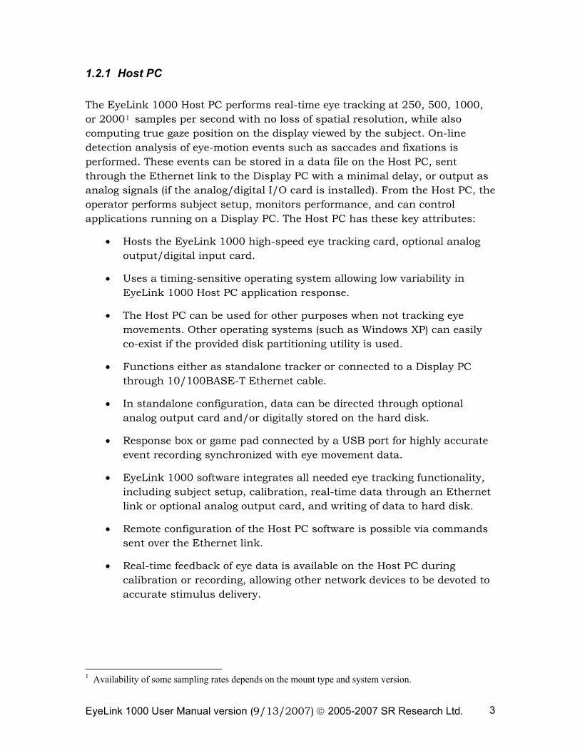
1.2.3 EyeLink 1000 Hardware Configurations
The EyeLink 1000 is available in two base hardware configurations (the Desktop Mount and the Tower Mount). These configurations differ in the type of
EyeLink 1000 User Manual version (9/13/2007) © 2005-2007 SR Research Ltd. 5
mounting used for the EyeLink CL high speed camera and low output infrared illuminator module.
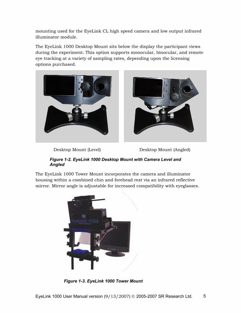
The EyeLink 1000 Desktop Mount sits below the display the participant views during the experiment. This option supports monocular, binocular, and remote eye tracking at a variety of sampling rates, depending upon the licensing options purchased.
Desktop Mount (Level) Desktop Mount (Angled)
Figure 1-2. EyeLink 1000 Desktop Mount with Camera Level and Angled
The EyeLink 1000 Tower Mount incorporates the camera and illuminator housing within a combined chin and forehead rest via an infrared reflective mirror. Mirror angle is adjustable for increased compatibility with eyeglasses.
Figure 1-3. EyeLink 1000 Tower Mount
EyeLink 1000 User Manual version (9/13/2007) © 2005-2007 SR Research Ltd. 6
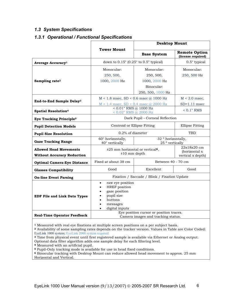
1.3 System Specifications 1.3.1 Operational / Functional Specifications
Desktop Mount
Tower Mount Base System Remote Option
(license required)
Average Accuracy1 down to 0.15° (0.25° to 0.5° typical) 0.5° typical
Sampling rate2
Monocular:
250, 500,
1000, 2000 Hz
Monocular:
250, 500,
1000, 2000 Hz
Binocular:
250, 500, 1000 Hz
Monocular:
250, 500 Hz
End-to-End Sample Delay3 M < 1.8 msec, SD < 0.6 msec @ 1000 Hz
M < 1.4 msec, SD < 0.4 msec @ 2000 Hz
M < 3.0 msec,
SD=1.11 msec
Spatial Resolution4 < 0.01° RMS @ 1000 Hz < 0.02° RMS @ 2000 Hz < 0.1° RMS
Eye Tracking Principle5 Dark Pupil - Corneal Reflection
Pupil Detection Models Centroid or Ellipse Fitting Ellipse Fitting
Pupil Size Resolution 0.2% of diameter TBD
Gaze Tracking Range 60° horizontally,
40° vertically 32 º horizontally,
25 º vertically
Allowed Head Movements Without Accuracy Reduction
±25 mm horizontal or vertical6, ±10 mm depth
22x18x20 cm (horizontal x
vertical x depth)
Optimal Camera-Eye Distance Fixed at about 38 cm Between 40 - 70 cm
Glasses Compatibility Good Excellent Good
On-line Event Parsing Fixation / Saccade / Blink / Fixation Update
EDF File and Link Data Types
• raw eye position • HREF position • gaze position • pupil size • buttons • messages • digital inputs
Real-Time Operator Feedback Eye position cursor or position traces. Camera images and tracking status.
1 Measured with real eye fixations at multiple screen positions on a per subject basis. 2 Availability of some sampling rates depends on the tracker version. Values in Table are Color Coded: EyeLink 1000 system; EyeLink 2000 system required 3 Time from physical event until first registered sample is available via Ethernet or Analog output. Optional data filter algorithm adds one sample delay for each filtering level. 4 Measured with an artificial pupil. 5 Pupil-Only tracking mode is available for use in head fixed conditions. 6 Binocular tracking with Desktop Mount can reduce allowed head movement to approx. 25 mm Horizontal and Vertical.
EyeLink 1000 User Manual version (9/13/2007) © 2005-2007 SR Research Ltd. 7
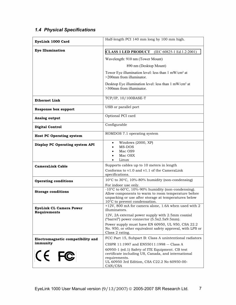
1.4 Physical Specifications
EyeLink 1000 Card Half-length PCI 140 mm long by 100 mm high.
Eye Illumination
CLASS 1 LED PRODUCT (IEC 60825-1 Ed.1.2:2001)
Wavelength: 910 nm (Tower Mount)
890 nm (Desktop Mount)
Tower Eye illumination level: less than 1 mW/cm² at >200mm from illuminator.
Desktop Eye illumination level: less than 1 mW/cm² at >300mm from illuminator.
Ethernet Link TCP/IP, 10/100BASE-T
Response box support USB or parallel port
Analog output Optional PCI card
Digital Control Configurable
Host PC Operating system ROMDOS 7.1 operating system
Display PC Operating system API • Windows (2000, XP) • MS-DOS • Mac OS9 • Mac OSX • Linux
CameraLink Cable Supports cables up to 10 meters in length Conforms to v1.0 and v1.1 of the CameraLink specifications.
Operating conditions 10°C to 30°C, 10%-80% humidity (non-condensing) For indoor use only.
Storage conditions -10°C to 60°C, 10%-90% humidity (non-condensing). Allow components to warm to room temperature before unpacking or use after storage at temperatures below 10°C to prevent condensation.
EyeLink CL Camera Power Requirements
+12V, 800 mA for camera alone, 1.6A when used with 2 illuminators. 12V, 2A external power supply with 2.5mm coaxial (“barrel”) power connector (5.5x2.5x9.5mm). Power supply must have EN 60950, UL 950, CSA 22.2 No. 950, or other equivalent safety approval, with LPS or Class 2 rating.
Electromagnetic compatibility and immunity
FCC Part 15, Subpart B: Class A unintentional radiators
CISPR 11:1997 and EN55011:1998 -- Class A 60950-1 (ed.1) Safety of ITE Equipment. CB test certificate including US, Canada, and international requirements. UL 60950 3rd Edition, CSA C22.2 No 60950-00-CAN/CSA
EyeLink 1000 User Manual version (9/13/2007) © 2005-2007 SR Research Ltd. 8
CLASS 1 LED DEVICE IEC 60825-1 (Ed. 1.2:2001)
NOTE: This equipment has been tested and found to comply with the limits for a Class A digital device, pursuant to part 15 of the FCC Rules. These limits are designed to provide reasonable protection against harmful interference when the equipment is operated in a commercial environment. This equipment generates, uses, and can radiate radio frequency energy and, if not installed and used in accordance with the instruction manual, may cause harmful interference to radio communications. Operation of this equipment in a residential area is likely to cause harmful interference in which case the user will be required to correct the interference at the users’ expense. WARNING: Changes or modifications not expressly approved by SR Research Ltd. could void the user’s warranty and authority to operate the equipment.
EyeLink 1000 User Manual version (9/13/2007) © 2005-2007 SR Research Ltd. 9
2. EyeLink 1000 Tracker Application Operation
2.1 Starting the Host Tracker
Follow these simple steps to start the EyeLink 1000 Host Tracker:
a) Start your Host PC
b) If your system was installed with a disk partitioning tool, select the EyeLink partition
c) Type the following at the command prompt:
T [ENTER]
d) If the EyeLink 1000 Tracker program does not start, type the following at the command prompt:
CD ELCL\EXE [ENTER]
ELCL.EXE [ENTER]
The EyeLink 1000 Tracker application should start and display the Off-line tracker screen.
2.2 Modes of Operation
The EyeLink 1000 is a multipurpose, high resolution, real-time processing system. It is designed to be used in 2 different operating modes:
Link: In this mode, the eye tracker is partially controlled by the Display PC via commands sent over the Ethernet link. The degree of Display PC control is dependent only on the display application itself. With appropriate programming, it is possible to have full control of the tracker via the Display PC. The SR Research Experiment Builder software and various low level programming interfaces have been designed to facilitate interacting with the Host PC. A common scenario is to have the application on the Display PC control the eye tracker to start subject setup and calibration, while the operator uses the EyeLink Host PC's keyboard to remotely monitor and control data collection, perform drift correction, and handle problems if they occur.
Standalone: In this mode, the eye tracker is an independent system, controlled by the operator by the Host PC tracker interface and keyboard. The Host PC is still connected to a display-generating computer for the purpose of displaying calibration targets only. There are 2 possible data output modes
EyeLink 1000 User Manual version (9/13/2007) © 2005-2007 SR Research Ltd. 10
when running the EyeLink 1000 as a standalone system. These output modes are not exclusive and include:
a) Analog output. Using the optional analog output card, data is available in analog format. Analog output options are configurable via the “Set Options” screen and in the ANALOG.INI initialization file.
b) File Output. Eye data is available in the EyeLink EDF file format (see Chapter 4 “Data File”). This can be converted to an ACSII file format using the EDF2ASC conversion utility or analyzed with EyeLink Data Viewer. File output options are configurable via the “Set Options” screen.
2.3 EyeLink 1000 Host PC Navigation
The EyeLink 1000 tracker interface consists of a set of setup and monitoring screens, which may be navigated by means of the Host PC mouse, key shortcuts, or from the Display PC application via link commands.
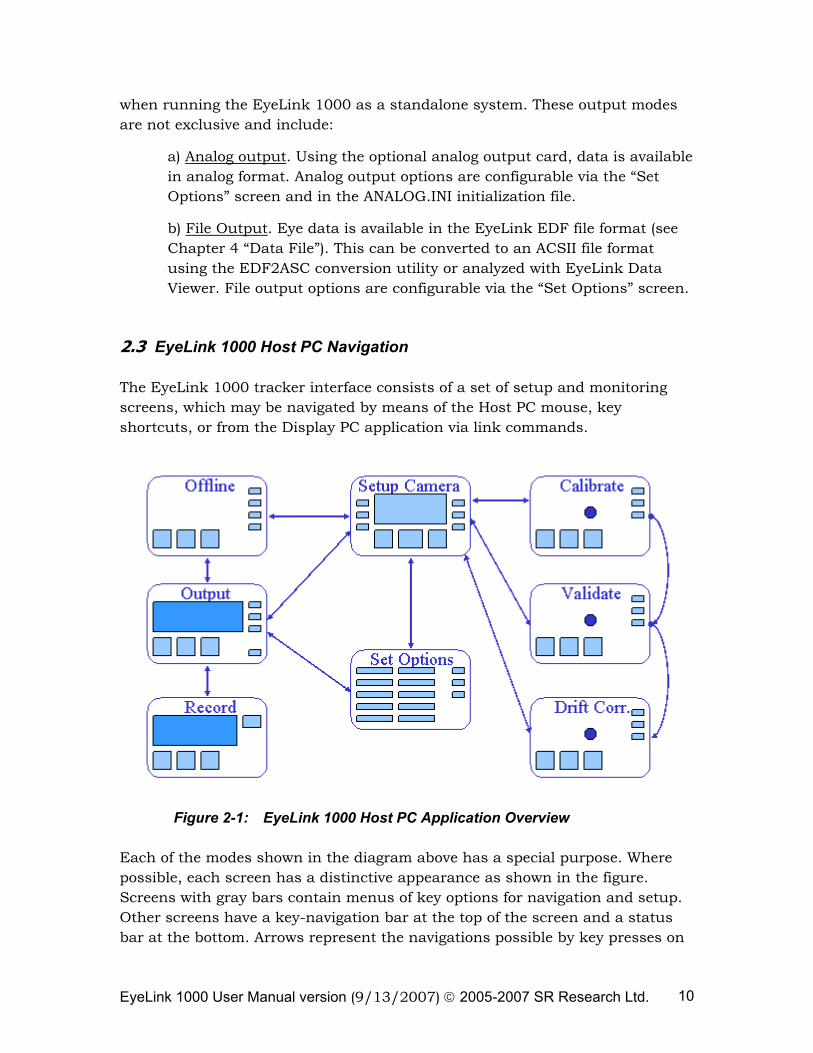
Figure 2-1: EyeLink 1000 Host PC Application Overview
Each of the modes shown in the diagram above has a special purpose. Where possible, each screen has a distinctive appearance as shown in the figure. Screens with gray bars contain menus of key options for navigation and setup. Other screens have a key-navigation bar at the top of the screen and a status bar at the bottom. Arrows represent the navigations possible by key presses on
EyeLink 1000 User Manual version (9/13/2007) © 2005-2007 SR Research Ltd. 11
the Host PC keyboard or via button selection using the Host PC mouse. All modes are accessible from the Display PC by link control. Note the central role of the Camera Setup menu: it serves as the mode control during subject setup.
The functions of each mode and the main access keys to other modes are summarized below. Pressing the on screen Help button or hitting the F1 key will open a screen sensitive Help menu listing all available key shortcuts for that screen. From any screen, the key combination ‘CTRL+ALT+Q’ will exit the EyeLink tracker program.
2.3.1 Offline Screen
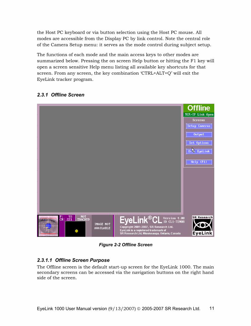
Figure 2-2 Offline Screen
2.3.1.1 Offline Screen Purpose The Offline screen is the default start-up screen for the EyeLink 1000. The main secondary screens can be accessed via the navigation buttons on the right hand side of the screen.
EyeLink 1000 User Manual version (9/13/2007) © 2005-2007 SR Research Ltd. 12
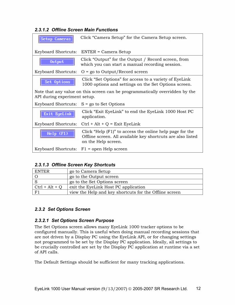
2.3.1.2 Offline Screen Main Functions Click “Camera Setup” for the Camera Setup screen.
Keyboard Shortcuts: ENTER = Camera Setup
Click “Output” for the Output / Record screen, from which you can start a manual recording session.
Keyboard Shortcuts: O = go to Output/Record screen
Click “Set Options” for access to a variety of EyeLink 1000 options and settings on the Set Options screen.
Note that any value on this screen can be programmatically overridden by the API during experiment setup.
Keyboard Shortcuts: S = go to Set Options
Click “Exit EyeLink” to end the EyeLink 1000 Host PC application.
Keyboard Shortcuts: Ctrl + Alt + Q = Exit EyeLink
Click “Help (F1)” to access the online help page for the Offline screen. All available key shortcuts are also listed on the Help screen.
Keyboard Shortcuts: F1 = open Help screen
2.3.1.3 Offline Screen Key Shortcuts ENTER go to Camera Setup O go to the Output screen S go to the Set Options screen Ctrl + Alt + Q exit the EyeLink Host PC application F1 view the Help and key shortcuts for the Offline screen
2.3.2 Set Options Screen
2.3.2.1 Set Options Screen Purpose The Set Options screen allows many EyeLink 1000 tracker options to be configured manually. This is useful when doing manual recording sessions that are not driven by a Display PC using the EyeLink API, or for changing settings not programmed to be set by the Display PC application. Ideally, all settings to be crucially controlled are set by the Display PC application at runtime via a set of API calls. The Default Settings should be sufficient for many tracking applications.
EyeLink 1000 User Manual version (9/13/2007) © 2005-2007 SR Research Ltd. 13
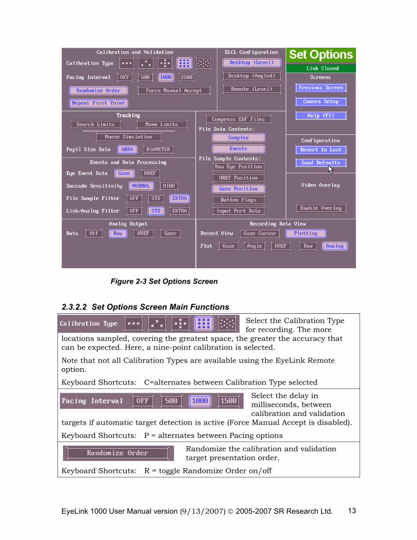
Figure 2-3 Set Options Screen
2.3.2.2 Set Options Screen Main Functions Select the Calibration Type for recording. The more
locations sampled, covering the greatest space, the greater the accuracy that can be expected. Here, a nine-point calibration is selected.
Note that not all Calibration Types are available using the EyeLink Remote option.
Keyboard Shortcuts: C=alternates between Calibration Type selected
Select the delay in milliseconds, between calibration and validation
targets if automatic target detection is active (Force Manual Accept is disabled).
Keyboard Shortcuts: P = alternates between Pacing options
Randomize the calibration and validation target presentation order.
Keyboard Shortcuts: R = toggle Randomize Order on/off
EyeLink 1000 User Manual version (9/13/2007) © 2005-2007 SR Research Ltd. 14
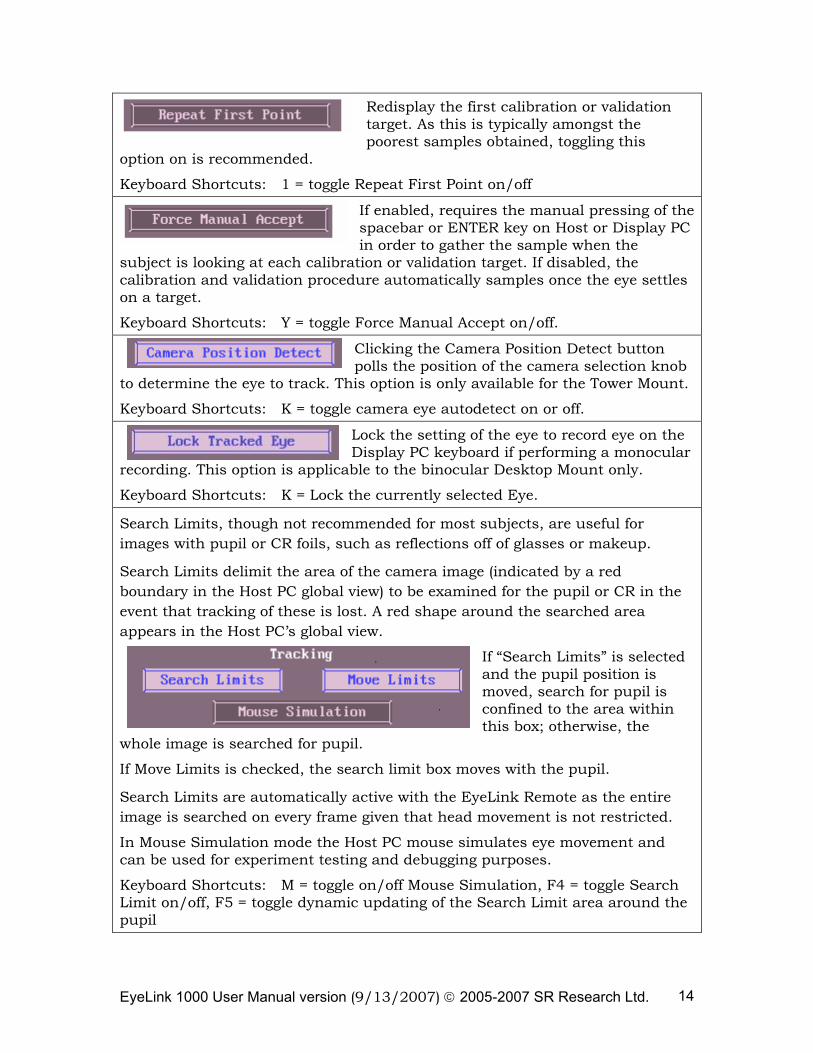
Redisplay the first calibration or validation target. As this is typically amongst the poorest samples obtained, toggling this
option on is recommended.
Keyboard Shortcuts: 1 = toggle Repeat First Point on/off
If enabled, requires the manual pressing of the spacebar or ENTER key on Host or Display PC in order to gather the sample when the
subject is looking at each calibration or validation target. If disabled, the calibration and validation procedure automatically samples once the eye settles on a target.
Keyboard Shortcuts: Y = toggle Force Manual Accept on/off.
Clicking the Camera Position Detect button polls the position of the camera selection knob
to determine the eye to track. This option is only available for the Tower Mount.
Keyboard Shortcuts: K = toggle camera eye autodetect on or off.
Lock the setting of the eye to record eye on the Display PC keyboard if performing a monocular
recording. This option is applicable to the binocular Desktop Mount only.
Keyboard Shortcuts: K = Lock the currently selected Eye.
Search Limits, though not recommended for most subjects, are useful for images with pupil or CR foils, such as reflections off of glasses or makeup.
Search Limits delimit the area of the camera image (indicated by a red boundary in the Host PC global view) to be examined for the pupil or CR in the event that tracking of these is lost. A red shape around the searched area appears in the Host PC’s global view.
If “Search Limits” is selected and the pupil position is moved, search for pupil is confined to the area within this box; otherwise, the
whole image is searched for pupil.
If Move Limits is checked, the search limit box moves with the pupil.
Search Limits are automatically active with the EyeLink Remote as the entire image is searched on every frame given that head movement is not restricted.
In Mouse Simulation mode the Host PC mouse simulates eye movement and can be used for experiment testing and debugging purposes.
Keyboard Shortcuts: M = toggle on/off Mouse Simulation, F4 = toggle Search Limit on/off, F5 = toggle dynamic updating of the Search Limit area around the pupil
EyeLink 1000 User Manual version (9/13/2007) © 2005-2007 SR Research Ltd. 15
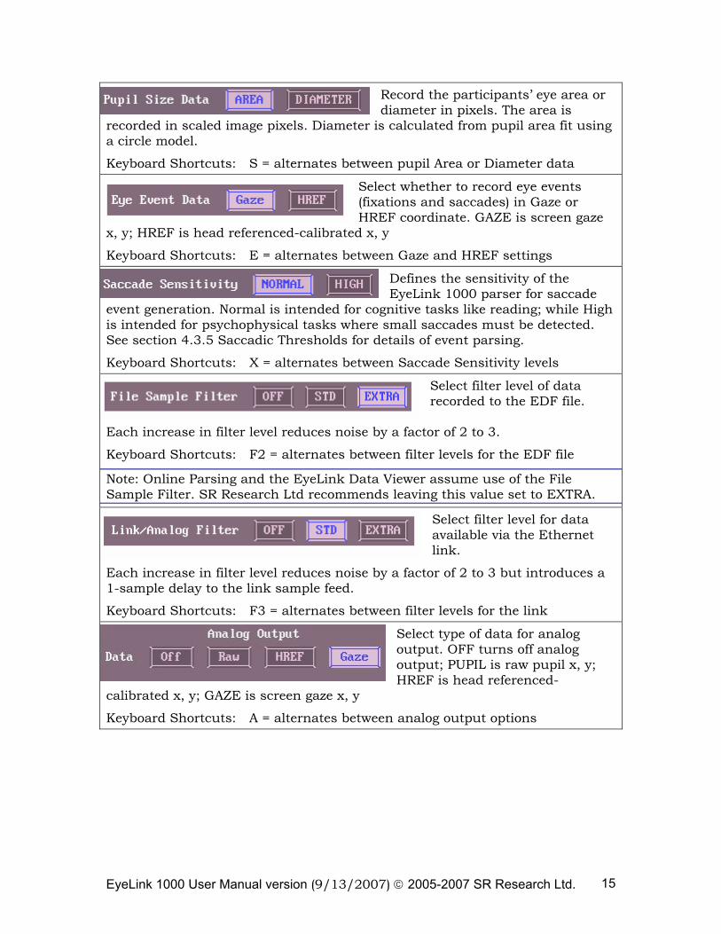
Record the participants’ eye area or diameter in pixels. The area is
recorded in scaled image pixels. Diameter is calculated from pupil area fit using a circle model.
Keyboard Shortcuts: S = alternates between pupil Area or Diameter data
Select whether to record eye events (fixations and saccades) in Gaze or HREF coordinate. GAZE is screen gaze
x, y; HREF is head referenced-calibrated x, y
Keyboard Shortcuts: E = alternates between Gaze and HREF settings
Defines the sensitivity of the EyeLink 1000 parser for saccade
event generation. Normal is intended for cognitive tasks like reading; while High is intended for psychophysical tasks where small saccades must be detected. See section 4.3.5 Saccadic Thresholds for details of event parsing.
Keyboard Shortcuts: X = alternates between Saccade Sensitivity levels
Select filter level of data recorded to the EDF file.
Each increase in filter level reduces noise by a factor of 2 to 3.
Keyboard Shortcuts: F2 = alternates between filter levels for the EDF file
Note: Online Parsing and the EyeLink Data Viewer assume use of the File Sample Filter. SR Research Ltd recommends leaving this value set to EXTRA.
Select filter level for data available via the Ethernet link.
Each increase in filter level reduces noise by a factor of 2 to 3 but introduces a 1-sample delay to the link sample feed.
Keyboard Shortcuts: F3 = alternates between filter levels for the link
Select type of data for analog output. OFF turns off analog output; PUPIL is raw pupil x, y; HREF is head referenced-
calibrated x, y; GAZE is screen gaze x, y
Keyboard Shortcuts: A = alternates between analog output options
EyeLink 1000 User Manual version (9/13/2007) © 2005-2007 SR Research Ltd. 16
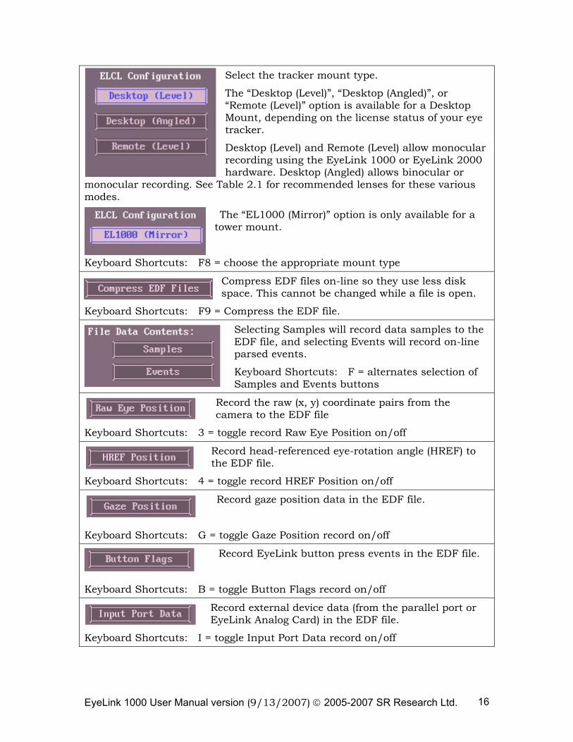
Select the tracker mount type.
The “Desktop (Level)”, “Desktop (Angled)”, or “Remote (Level)” option is available for a Desktop Mount, depending on the license status of your eye tracker.
Desktop (Level) and Remote (Level) allow monocular recording using the EyeLink 1000 or EyeLink 2000 hardware. Desktop (Angled) allows binocular or
monocular recording. See Table 2.1 for recommended lenses for these various modes.
The “EL1000 (Mirror)” option is only available for a tower mount.
Keyboard Shortcuts: F8 = choose the appropriate mount type
Compress EDF files on-line so they use less disk space. This cannot be changed while a file is open.
Keyboard Shortcuts: F9 = Compress the EDF file.
Selecting Samples will record data samples to the EDF file, and selecting Events will record on-line parsed events.
Keyboard Shortcuts: F = alternates selection of Samples and Events buttons
Record the raw (x, y) coordinate pairs from the camera to the EDF file
Keyboard Shortcuts: 3 = toggle record Raw Eye Position on/off
Record head-referenced eye-rotation angle (HREF) to the EDF file.
Keyboard Shortcuts: 4 = toggle record HREF Position on/off
Record gaze position data in the EDF file.
Keyboard Shortcuts: G = toggle Gaze Position record on/off
Record EyeLink button press events in the EDF file.
Keyboard Shortcuts: B = toggle Button Flags record on/off
Record external device data (from the parallel port or EyeLink Analog Card) in the EDF file.
Keyboard Shortcuts: I = toggle Input Port Data record on/off
EyeLink 1000 User Manual version (9/13/2007) © 2005-2007 SR Research Ltd. 17
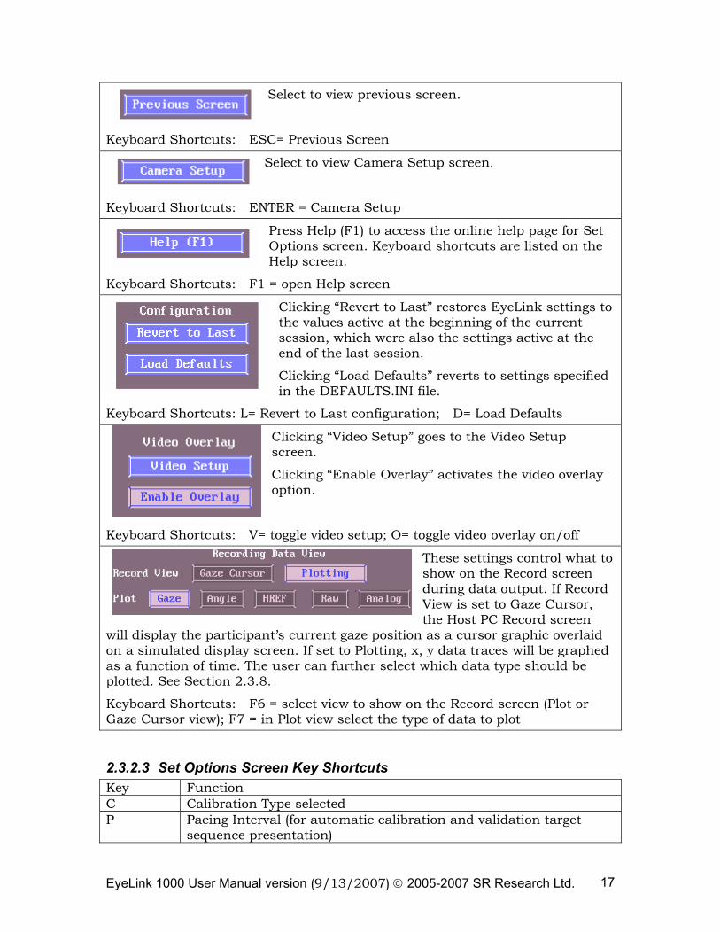
Select to view previous screen.
Keyboard Shortcuts: ESC= Previous Screen
Select to view Camera Setup screen.
Keyboard Shortcuts: ENTER = Camera Setup
Press Help (F1) to access the online help page for Set Options screen. Keyboard shortcuts are listed on the Help screen.
Keyboard Shortcuts: F1 = open Help screen
Clicking “Revert to Last” restores EyeLink settings to the values active at the beginning of the current session, which were also the settings active at the end of the last session.
Clicking “Load Defaults” reverts to settings specified in the DEFAULTS.INI file.
Keyboard Shortcuts: L= Revert to Last configuration; D= Load Defaults
Clicking “Video Setup” goes to the Video Setup screen.
Clicking “Enable Overlay” activates the video overlay option.
Keyboard Shortcuts: V= toggle video setup; O= toggle video overlay on/off
These settings control what to show on the Record screen during data output. If Record View is set to Gaze Cursor, the Host PC Record screen
will display the participant’s current gaze position as a cursor graphic overlaid on a simulated display screen. If set to Plotting, x, y data traces will be graphed as a function of time. The user can further select which data type should be plotted. See Section 2.3.8.
Keyboard Shortcuts: F6 = select view to show on the Record screen (Plot or Gaze Cursor view); F7 = in Plot view select the type of data to plot
2.3.2.3 Set Options Screen Key Shortcuts Key Function C Calibration Type selected P Pacing Interval (for automatic calibration and validation target
sequence presentation)
EyeLink 1000 User Manual version (9/13/2007) © 2005-2007 SR Research Ltd. 18
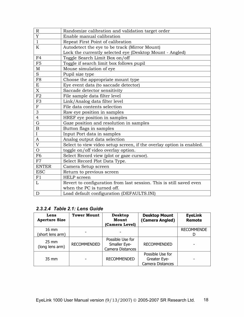
R Randomize calibration and validation target order Y Enable manual calibration 1 Repeat First Point of calibration K Autodetect the eye to be track (Mirror Mount)
Lock the currently selected eye (Desktop Mount - Angled) F4 Toggle Search Limit Box on/off F5 Toggle if search limit box follows pupil M Mouse simulation of eye S Pupil size type F8 Choose the appropriate mount type E Eye event data (to saccade detector) X Saccade detector sensitivity F2 File sample data filter level F3 Link/Analog data filter level F File data contents selection 3 Raw eye position in samples 4 HREF eye position in samples G Gaze position and resolution in samples B Button flags in samples I Input Port data in samples A Analog output data selection V Select to view video setup screen, if the overlay option is enabled. O toggle on/off video overlay option. F6 Select Record view (plot or gaze cursor). F7 Select Record Plot Data Type. ENTER Camera Setup screen ESC Return to previous screen F1 HELP screen L Revert to configuration from last session. This is still saved even
when the PC is turned off. D Load default configuration (DEFAULTS.INI)
2.3.2.4 Table 2.1: Lens Guide Lens
Aperture Size Tower Mount Desktop
Mount (Camera Level)
Desktop Mount (Camera Angled)
EyeLink Remote
16 mm (short lens arm) - - RECOMMENDE
D
25 mm (long lens arm) RECOMMENDED
Possible Use for Smaller Eye-
Camera DistancesRECOMMENDED -
35 mm - RECOMMENDED Possible Use for
Greater Eye-Camera Distances
-
EyeLink 1000 User Manual version (9/13/2007) © 2005-2007 SR Research Ltd. 19
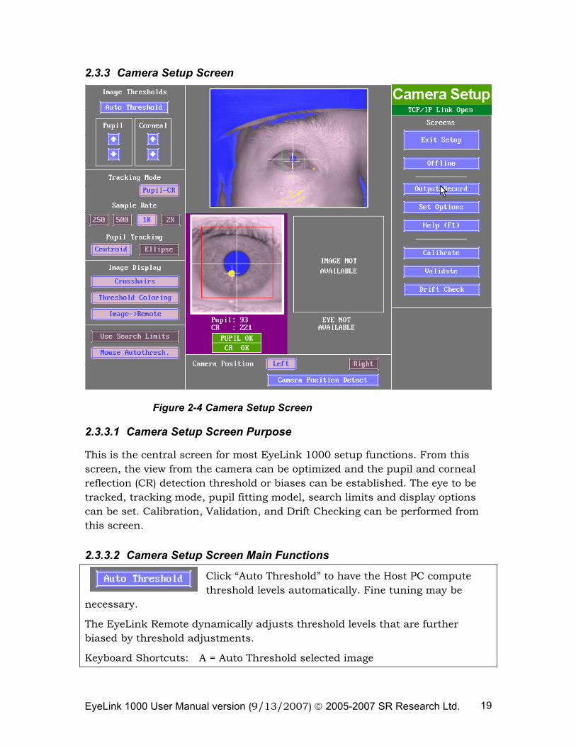
2.3.3 Camera Setup Screen
Figure 2-4 Camera Setup Screen
2.3.3.1 Camera Setup Screen Purpose
This is the central screen for most EyeLink 1000 setup functions. From this screen, the view from the camera can be optimized and the pupil and corneal reflection (CR) detection threshold or biases can be established. The eye to be tracked, tracking mode, pupil fitting model, search limits and display options can be set. Calibration, Validation, and Drift Checking can be performed from this screen.
2.3.3.2 Camera Setup Screen Main Functions
Click “Auto Threshold” to have the Host PC compute threshold levels automatically. Fine tuning may be
necessary.
The EyeLink Remote dynamically adjusts threshold levels that are further biased by threshold adjustments.
Keyboard Shortcuts: A = Auto Threshold selected image
EyeLink 1000 User Manual version (9/13/2007) © 2005-2007 SR Research Ltd. 20
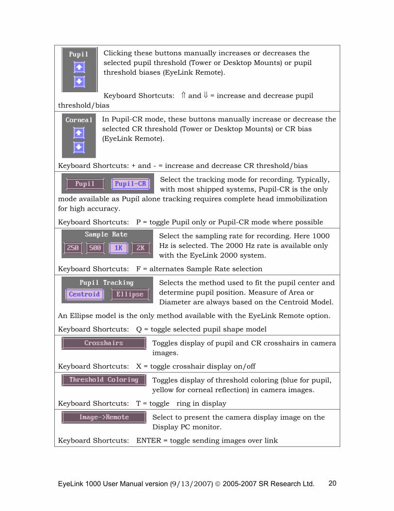
Clicking these buttons manually increases or decreases the selected pupil threshold (Tower or Desktop Mounts) or pupil threshold biases (EyeLink Remote).
Keyboard Shortcuts: ⇑ and ⇓ = increase and decrease pupil
threshold/bias
In Pupil-CR mode, these buttons manually increase or decrease the selected CR threshold (Tower or Desktop Mounts) or CR bias (EyeLink Remote).
Keyboard Shortcuts: + and - = increase and decrease CR threshold/bias
Select the tracking mode for recording. Typically, with most shipped systems, Pupil-CR is the only
mode available as Pupil alone tracking requires complete head immobilization for high accuracy.
Keyboard Shortcuts: P = toggle Pupil only or Pupil-CR mode where possible
Select the sampling rate for recording. Here 1000 Hz is selected. The 2000 Hz rate is available only with the EyeLink 2000 system.
Keyboard Shortcuts: F = alternates Sample Rate selection
Selects the method used to fit the pupil center and determine pupil position. Measure of Area or Diameter are always based on the Centroid Model.
An Ellipse model is the only method available with the EyeLink Remote option.
Keyboard Shortcuts: Q = toggle selected pupil shape model
Toggles display of pupil and CR crosshairs in camera images.
Keyboard Shortcuts: X = toggle crosshair display on/off
Toggles display of threshold coloring (blue for pupil, yellow for corneal reflection) in camera images.
Keyboard Shortcuts: T = toggle ring in display
Select to present the camera display image on the Display PC monitor.
Keyboard Shortcuts: ENTER = toggle sending images over link
EyeLink 1000 User Manual version (9/13/2007) © 2005-2007 SR Research Ltd. 21
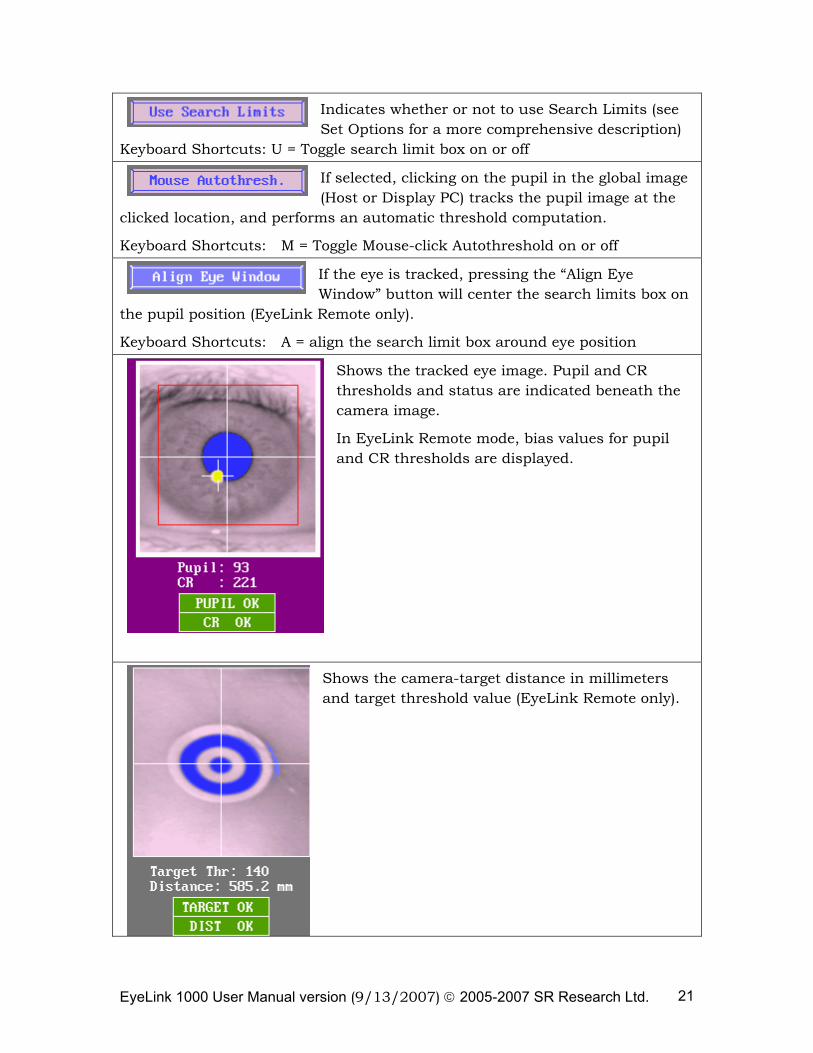
Indicates whether or not to use Search Limits (see Set Options for a more comprehensive description)
Keyboard Shortcuts: U = Toggle search limit box on or off
If selected, clicking on the pupil in the global image (Host or Display PC) tracks the pupil image at the
clicked location, and performs an automatic threshold computation.
Keyboard Shortcuts: M = Toggle Mouse-click Autothreshold on or off
If the eye is tracked, pressing the “Align Eye Window” button will center the search limits box on
the pupil position (EyeLink Remote only).
Keyboard Shortcuts: A = align the search limit box around eye position
Shows the tracked eye image. Pupil and CR thresholds and status are indicated beneath the camera image.
In EyeLink Remote mode, bias values for pupil and CR thresholds are displayed.
Shows the camera-target distance in millimeters and target threshold value (EyeLink Remote only).
EyeLink 1000 User Manual version (9/13/2007) © 2005-2007 SR Research Ltd. 22
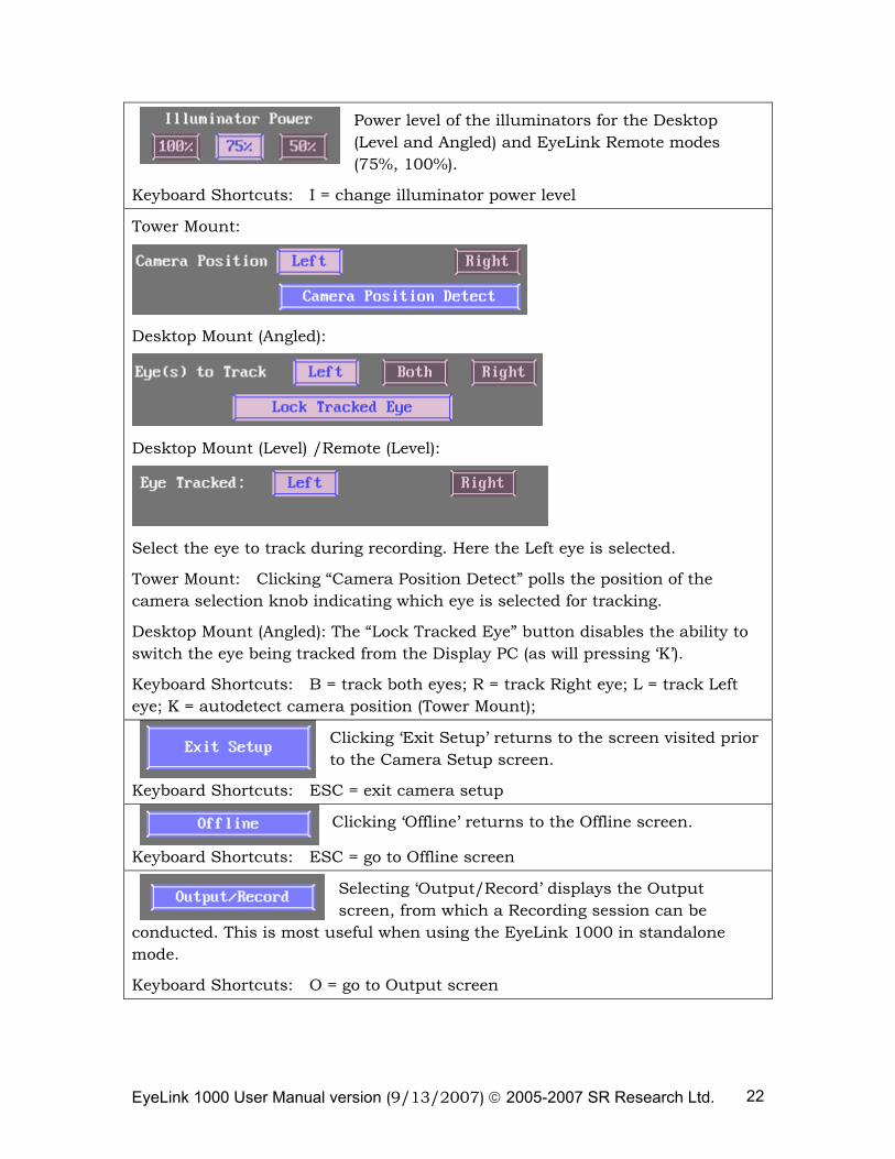
Power level of the illuminators for the Desktop (Level and Angled) and EyeLink Remote modes (75%, 100%).
Keyboard Shortcuts: I = change illuminator power level
Tower Mount:
Desktop Mount (Angled):
Desktop Mount (Level) /Remote (Level):
Select the eye to track during recording. Here the Left eye is selected.
Tower Mount: Clicking “Camera Position Detect” polls the position of the camera selection knob indicating which eye is selected for tracking.
Desktop Mount (Angled): The “Lock Tracked Eye” button disables the ability to switch the eye being tracked from the Display PC (as will pressing ‘K’).
Keyboard Shortcuts: B = track both eyes; R = track Right eye; L = track Left eye; K = autodetect camera position (Tower Mount);
Clicking ‘Exit Setup’ returns to the screen visited prior to the Camera Setup screen.
Keyboard Shortcuts: ESC = exit camera setup
Clicking ‘Offline’ returns to the Offline screen.
Keyboard Shortcuts: ESC = go to Offline screen
Selecting ‘Output/Record’ displays the Output screen, from which a Recording session can be
conducted. This is most useful when using the EyeLink 1000 in standalone mode.
Keyboard Shortcuts: O = go to Output screen
EyeLink 1000 User Manual version (9/13/2007) © 2005-2007 SR Research Ltd. 23
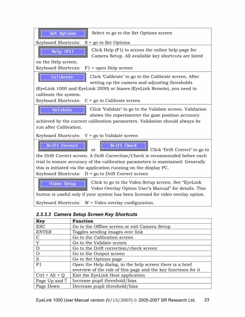
Select to go to the Set Options screen
Keyboard Shortcuts: S = go to Set Options
Click Help (F1) to access the online help page for Camera Setup. All available key shortcuts are listed
on the Help screen. Keyboard Shortcuts: F1 = open Help screen
Click ‘Calibrate’ to go to the Calibrate screen. After setting up the camera and adjusting thresholds
(EyeLink 1000 and EyeLink 2000) or biases (EyeLink Remote), you need to calibrate the system. Keyboard Shortcuts: C = go to Calibrate screen
Click ‘Validate’ to go to the Validate screen. Validation shows the experimenter the gaze position accuracy
achieved by the current calibration parameters. Validation should always be run after Calibration.
Keyboard Shortcuts: V = go to Validate screen
or Click ‘Drift Correct’ to go to the Drift Correct screen. A Drift Correction/Check is recommended before each trial to ensure accuracy of the calibration parameters is maintained. Generally this is initiated via the application running on the display PC. Keyboard Shortcuts: D = go to Drift Correct screen
Click to go to the Video Setup screen. See “EyeLink Video Overlay Option User’s Manual” for details. This
button is useful only if your system has been licensed for video overlay option.
Keyboard Shortcuts: W = Video overlay configuration.
2.3.3.3 Camera Setup Screen Key Shortcuts Key Function ESC Go to the Offline screen or exit Camera Setup ENTER Toggles sending images over link C Go to the Calibration screen V Go to the Validate screen D Go to the Drift correction/check screen O Go to the Output screen S Go to Set Options page F1 Open the Help dialog, in the help screen there is a brief
overview of the role of this page and the key functions for it Ctrl + Alt + Q Exit the EyeLink Host application Page Up and ⇑ Increase pupil threshold/bias Page Down Decrease pupil threshold/bias
EyeLink 1000 User Manual version (9/13/2007) © 2005-2007 SR Research Ltd. 24
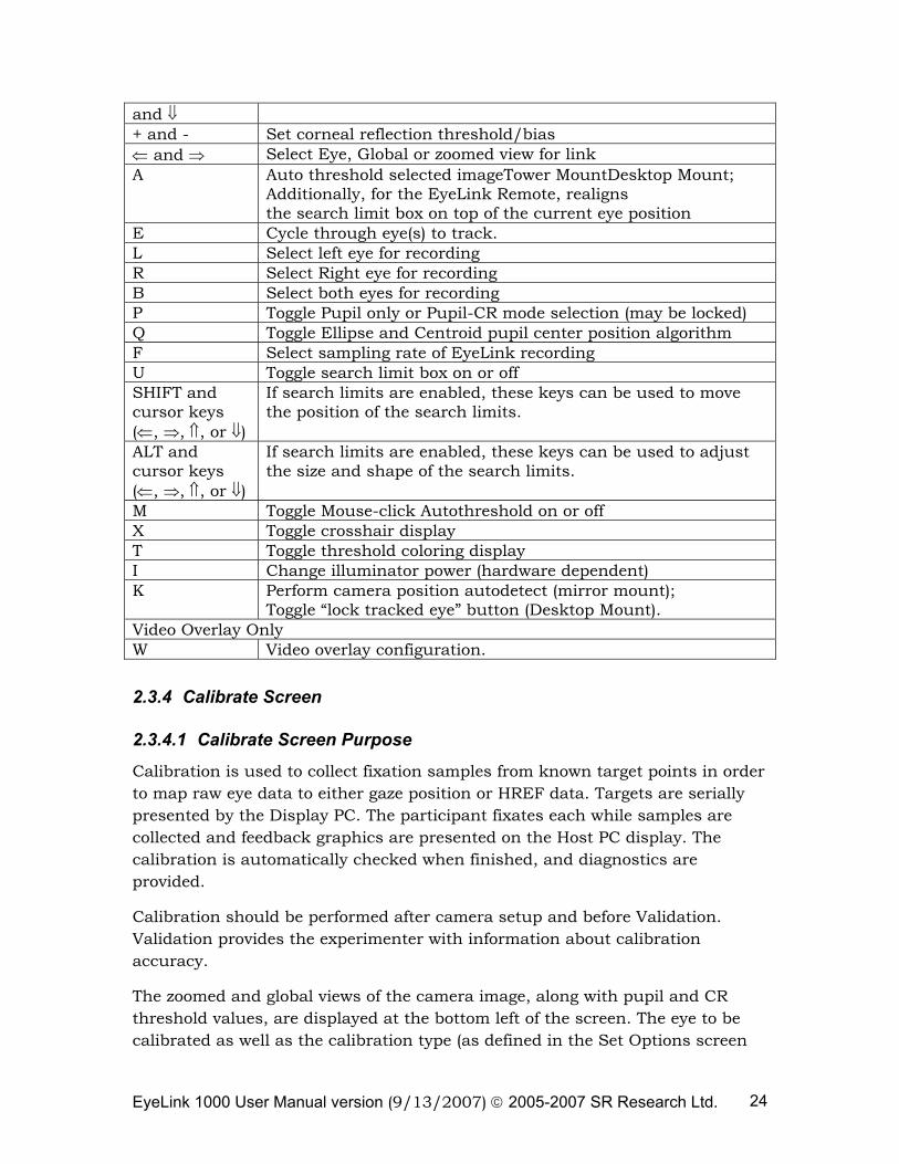
and ⇓ + and - Set corneal reflection threshold/bias ⇐ and ⇒ Select Eye, Global or zoomed view for link A Auto threshold selected imageTower MountDesktop Mount;
Additionally, for the EyeLink Remote, realigns the search limit box on top of the current eye position
E Cycle through eye(s) to track. L Select left eye for recording R Select Right eye for recording B Select both eyes for recording P Toggle Pupil only or Pupil-CR mode selection (may be locked) Q Toggle Ellipse and Centroid pupil center position algorithm F Select sampling rate of EyeLink recording U Toggle search limit box on or off SHIFT and cursor keys (⇐, ⇒, ⇑, or ⇓)
If search limits are enabled, these keys can be used to move the position of the search limits.
ALT and cursor keys (⇐, ⇒, ⇑, or ⇓)
If search limits are enabled, these keys can be used to adjust the size and shape of the search limits.
M Toggle Mouse-click Autothreshold on or off X Toggle crosshair display T Toggle threshold coloring display I Change illuminator power (hardware dependent) K Perform camera position autodetect (mirror mount);
Toggle “lock tracked eye” button (Desktop Mount). Video Overlay Only W Video overlay configuration.
2.3.4 Calibrate Screen
2.3.4.1 Calibrate Screen Purpose
Calibration is used to collect fixation samples from known target points in order to map raw eye data to either gaze position or HREF data. Targets are serially presented by the Display PC. The participant fixates each while samples are collected and feedback graphics are presented on the Host PC display. The calibration is automatically checked when finished, and diagnostics are provided.
Calibration should be performed after camera setup and before Validation. Validation provides the experimenter with information about calibration accuracy.
The zoomed and global views of the camera image, along with pupil and CR threshold values, are displayed at the bottom left of the screen. The eye to be calibrated as well as the calibration type (as defined in the Set Options screen
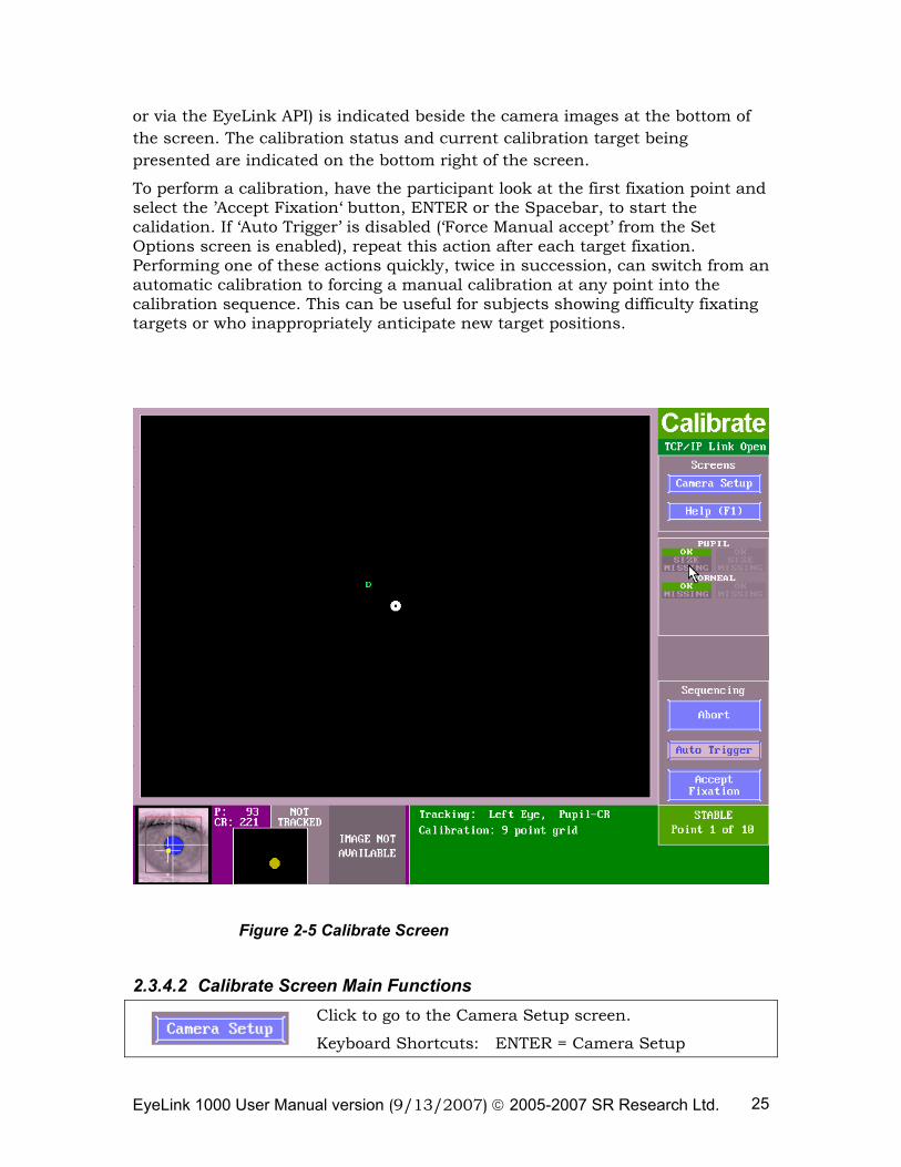
EyeLink 1000 User Manual version (9/13/2007) © 2005-2007 SR Research Ltd. 25
or via the EyeLink API) is indicated beside the camera images at the bottom of the screen. The calibration status and current calibration target being presented are indicated on the bottom right of the screen.
To perform a calibration, have the participant look at the first fixation point and select the ’Accept Fixation‘ button, ENTER or the Spacebar, to start the calidation. If ‘Auto Trigger’ is disabled (‘Force Manual accept’ from the Set Options screen is enabled), repeat this action after each target fixation. Performing one of these actions quickly, twice in succession, can switch from an automatic calibration to forcing a manual calibration at any point into the calibration sequence. This can be useful for subjects showing difficulty fixating targets or who inappropriately anticipate new target positions.
Figure 2-5 Calibrate Screen
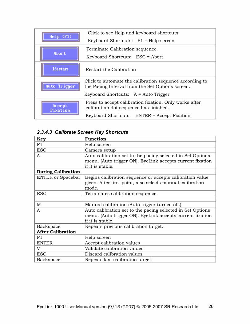
2.3.4.2 Calibrate Screen Main Functions Click to go to the Camera Setup screen.
Keyboard Shortcuts: ENTER = Camera Setup
EyeLink 1000 User Manual version (9/13/2007) © 2005-2007 SR Research Ltd. 26
Click to see Help and keyboard shortcuts.
Keyboard Shortcuts: F1 = Help screen
Terminate Calibration sequence.
Keyboard Shortcuts: ESC = Abort
Restart the Calibration
Click to automate the calibration sequence according to the Pacing Interval from the Set Options screen.
Keyboard Shortcuts: A = Auto Trigger
Press to accept calibration fixation. Only works after calibration dot sequence has finished.
Keyboard Shortcuts: ENTER = Accept Fixation
2.3.4.3 Calibrate Screen Key Shortcuts Key Function F1 Help screen ESC Camera setup A Auto calibration set to the pacing selected in Set Options
menu. (Auto trigger ON). EyeLink accepts current fixation if it is stable.
During Calibration ENTER or Spacebar Begins calibration sequence or accepts calibration value
given. After first point, also selects manual calibration mode.
ESC Terminates calibration sequence. M Manual calibration (Auto trigger turned off.) A Auto calibration set to the pacing selected in Set Options
menu. (Auto trigger ON). EyeLink accepts current fixation if it is stable.
Backspace Repeats previous calibration target. After Calibration F1 Help screen ENTER Accept calibration values V Validate calibration values ESC Discard calibration values Backspace Repeats last calibration target.
EyeLink 1000 User Manual version (9/13/2007) © 2005-2007 SR Research Ltd. 27
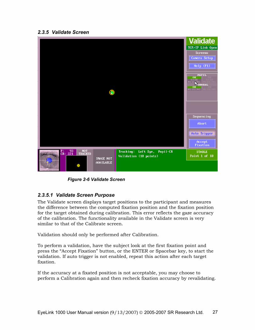
2.3.5 Validate Screen
Figure 2-6 Validate Screen
2.3.5.1 Validate Screen Purpose The Validate screen displays target positions to the participant and measures the difference between the computed fixation position and the fixation position for the target obtained during calibration. This error reflects the gaze accuracy of the calibration. The functionality available in the Validate screen is very similar to that of the Calibrate screen. Validation should only be performed after Calibration. To perform a validation, have the subject look at the first fixation point and press the “Accept Fixation” button, or the ENTER or Spacebar key, to start the validation. If auto trigger is not enabled, repeat this action after each target fixation. If the accuracy at a fixated position is not acceptable, you may choose to perform a Calibration again and then recheck fixation accuracy by revalidating.
EyeLink 1000 User Manual version (9/13/2007) © 2005-2007 SR Research Ltd. 28
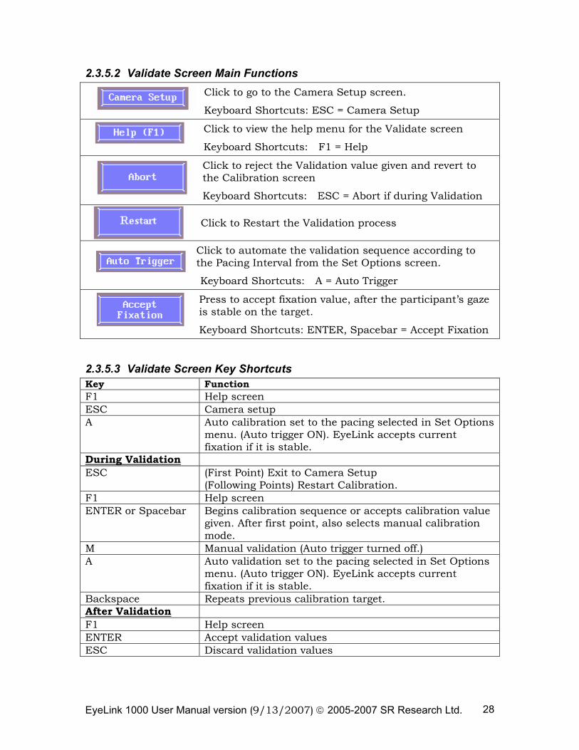
2.3.5.2 Validate Screen Main Functions Click to go to the Camera Setup screen.
Keyboard Shortcuts: ESC = Camera Setup
Click to view the help menu for the Validate screen
Keyboard Shortcuts: F1 = Help
Click to reject the Validation value given and revert to the Calibration screen
Keyboard Shortcuts: ESC = Abort if during Validation
Click to Restart the Validation process
Click to automate the validation sequence according to the Pacing Interval from the Set Options screen.
Keyboard Shortcuts: A = Auto Trigger
Press to accept fixation value, after the participant’s gaze is stable on the target.
Keyboard Shortcuts: ENTER, Spacebar = Accept Fixation
2.3.5.3 Validate Screen Key Shortcuts Key Function F1 Help screen ESC Camera setup A Auto calibration set to the pacing selected in Set Options
menu. (Auto trigger ON). EyeLink accepts current fixation if it is stable.
During Validation ESC (First Point) Exit to Camera Setup
(Following Points) Restart Calibration. F1 Help screen ENTER or Spacebar Begins calibration sequence or accepts calibration value
given. After first point, also selects manual calibration mode.
M Manual validation (Auto trigger turned off.) A Auto validation set to the pacing selected in Set Options
menu. (Auto trigger ON). EyeLink accepts current fixation if it is stable.
Backspace Repeats previous calibration target. After Validation F1 Help screen ENTER Accept validation values ESC Discard validation values
EyeLink 1000 User Manual version (9/13/2007) © 2005-2007 SR Research Ltd. 29
2.3.6 Drift Correct/Drift Check Screen
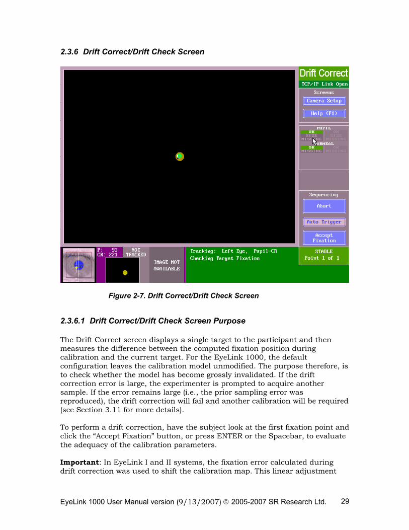
Figure 2-7. Drift Correct/Drift Check Screen
2.3.6.1 Drift Correct/Drift Check Screen Purpose The Drift Correct screen displays a single target to the participant and then measures the difference between the computed fixation position during calibration and the current target. For the EyeLink 1000, the default configuration leaves the calibration model unmodified. The purpose therefore, is to check whether the model has become grossly invalidated. If the drift correction error is large, the experimenter is prompted to acquire another sample. If the error remains large (i.e., the prior sampling error was reproduced), the drift correction will fail and another calibration will be required (see Section 3.11 for more details). To perform a drift correction, have the subject look at the first fixation point and click the “Accept Fixation” button, or press ENTER or the Spacebar, to evaluate the adequacy of the calibration parameters. Important: In EyeLink I and II systems, the fixation error calculated during drift correction was used to shift the calibration map. This linear adjustment
EyeLink 1000 User Manual version (9/13/2007) © 2005-2007 SR Research Ltd. 30
often greatly improved the overall accuracy for upcoming recording. However, with the EyeLink 1000 we have found that correcting the calibration map based on the drift correction result has no significant effect and can actually reduce fixation accuracy during recording. The default drift correction behavior of the EyeLink 1000 system in pupil-CR mode is to report the calculated fixation error without altering the calibration map in any way. Therefore the drift correction procedure is better viewed as a “Drift Checking” procedure in the EyeLink 1000.
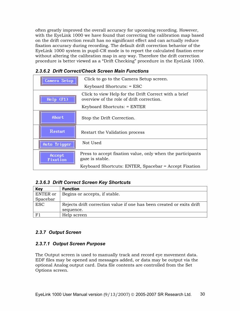
2.3.6.2 Drift Correct/Check Screen Main Functions Click to go to the Camera Setup screen.
Keyboard Shortcuts: = ESC
Click to view Help for the Drift Correct with a brief overview of the role of drift correction.
Keyboard Shortcuts: = ENTER Stop the Drift Correction.
Restart the Validation process
Not Used
Press to accept fixation value, only when the participants gaze is stable.
Keyboard Shortcuts: ENTER, Spacebar = Accept Fixation
2.3.6.3 Drift Correct Screen Key Shortcuts Key Function ENTER or Spacebar
Begins or accepts, if stable.
ESC Rejects drift correction value if one has been created or exits drift sequence.
F1 Help screen
2.3.7 Output Screen
2.3.7.1 Output Screen Purpose The Output screen is used to manually track and record eye movement data. EDF files may be opened and messages added, or data may be output via the optional Analog output card. Data file contents are controlled from the Set Options screen.
EyeLink 1000 User Manual version (9/13/2007) © 2005-2007 SR Research Ltd. 31
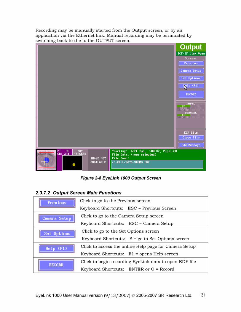
Recording may be manually started from the Output screen, or by an application via the Ethernet link. Manual recording may be terminated by switching back to the to the OUTPUT screen.
Figure 2-8 EyeLink 1000 Output Screen
2.3.7.2 Output Screen Main Functions Click to go to the Previous screen
Keyboard Shortcuts: ESC = Previous Screen
Click to go to the Camera Setup screen
Keyboard Shortcuts: ESC = Camera Setup
Click to go to the Set Options screen
Keyboard Shortcuts: S = go to Set Options screen
Click to access the online Help page for Camera Setup
Keyboard Shortcuts: F1 = opens Help screen
Click to begin recording EyeLink data to open EDF file
Keyboard Shortcuts: ENTER or O = Record
EyeLink 1000 User Manual version (9/13/2007) © 2005-2007 SR Research Ltd. 32
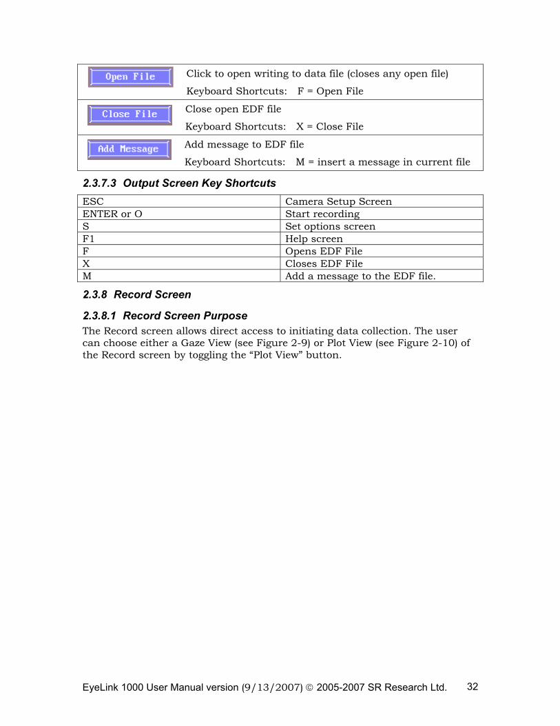
Click to open writing to data file (closes any open file)
Keyboard Shortcuts: F = Open File
Close open EDF file
Keyboard Shortcuts: X = Close File
Add message to EDF file
Keyboard Shortcuts: M = insert a message in current file
2.3.7.3 Output Screen Key Shortcuts ESC Camera Setup Screen ENTER or O Start recording S Set options screen F1 Help screen F Opens EDF File X Closes EDF File M Add a message to the EDF file.
2.3.8 Record Screen
2.3.8.1 Record Screen Purpose The Record screen allows direct access to initiating data collection. The user can choose either a Gaze View (see Figure 2-9) or Plot View (see Figure 2-10) of the Record screen by toggling the “Plot View” button.
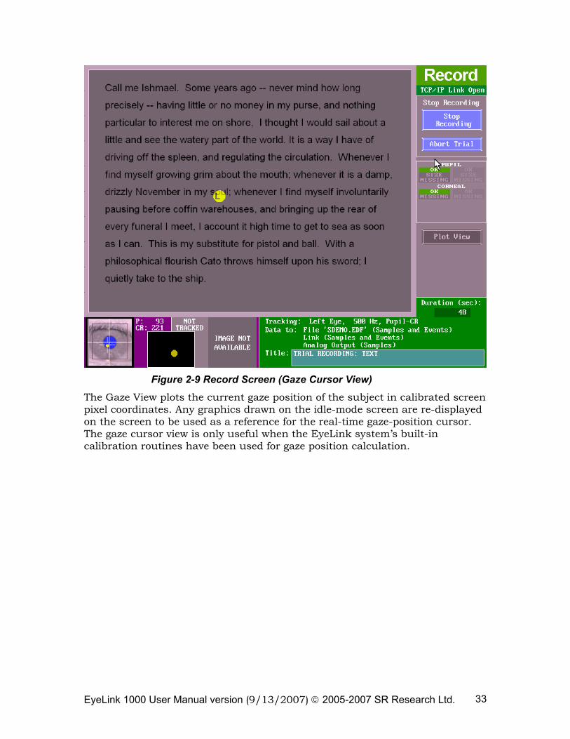
EyeLink 1000 User Manual version (9/13/2007) © 2005-2007 SR Research Ltd. 33
Figure 2-9 Record Screen (Gaze Cursor View)
The Gaze View plots the current gaze position of the subject in calibrated screen pixel coordinates. Any graphics drawn on the idle-mode screen are re-displayed on the screen to be used as a reference for the real-time gaze-position cursor. The gaze cursor view is only useful when the EyeLink system’s built-in calibration routines have been used for gaze position calculation.

EyeLink 1000 User Manual version (9/13/2007) © 2005-2007 SR Research Ltd. 34
Figure 2-10 Record Screen (Plot View)
The Plot View displays the x, y data traces as a function of time. The type of data to be plotted can be configured at the Set Options screen. Since raw data can also be displayed in the plot view, this view is useful in any data output mode, even when calibration has not been performed.
2.3.8.2 Record Screen Main Functions (Gaze View and Plot View)
Stops the recording of data to the EDF file.
Keyboard Shortcuts: ESC = Stop Recording
Abort the trial recording.
Keyboard Shortcuts: CTRL + ALT + A = Abort Trial
Instead of showing the gaze cursor, plots the x, y eye data being acquired as a function of time.
Keyboard Shortcuts: G = toggle between Gaze Cursor and Plot Views
Performs online drift check for data being acquired.
Keyboard Shortcuts: F = perform on-line calibration accuracy check
2.3.8.3 Buttons Used in the Plot View
EyeLink 1000 User Manual version (9/13/2007) © 2005-2007 SR Research Ltd. 35
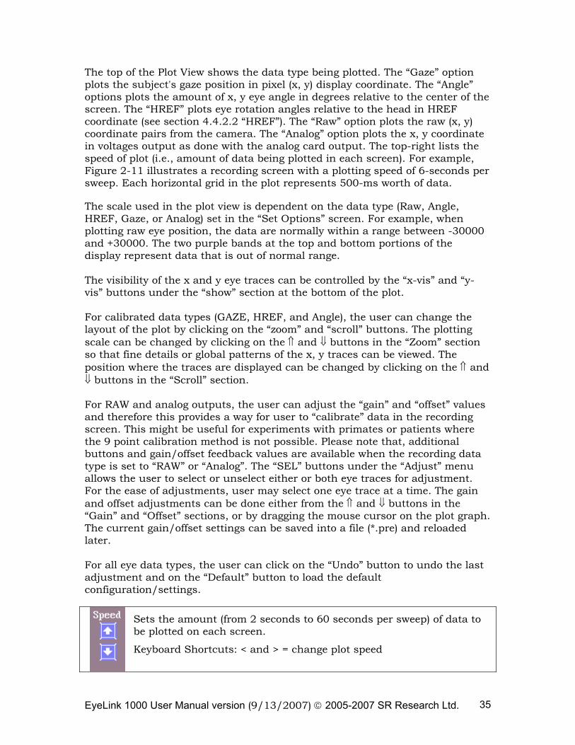
The top of the Plot View shows the data type being plotted. The “Gaze” option plots the subject's gaze position in pixel (x, y) display coordinate. The “Angle” options plots the amount of x, y eye angle in degrees relative to the center of the screen. The “HREF” plots eye rotation angles relative to the head in HREF coordinate (see section 4.4.2.2 “HREF”). The “Raw” option plots the raw (x, y) coordinate pairs from the camera. The “Analog” option plots the x, y coordinate in voltages output as done with the analog card output. The top-right lists the speed of plot (i.e., amount of data being plotted in each screen). For example, Figure 2-11 illustrates a recording screen with a plotting speed of 6-seconds per sweep. Each horizontal grid in the plot represents 500-ms worth of data. The scale used in the plot view is dependent on the data type (Raw, Angle, HREF, Gaze, or Analog) set in the “Set Options” screen. For example, when plotting raw eye position, the data are normally within a range between -30000 and +30000. The two purple bands at the top and bottom portions of the display represent data that is out of normal range. The visibility of the x and y eye traces can be controlled by the “x-vis” and “y-vis” buttons under the “show” section at the bottom of the plot. For calibrated data types (GAZE, HREF, and Angle), the user can change the layout of the plot by clicking on the “zoom” and “scroll” buttons. The plotting scale can be changed by clicking on the ⇑ and ⇓ buttons in the “Zoom” section so that fine details or global patterns of the x, y traces can be viewed. The position where the traces are displayed can be changed by clicking on the ⇑ and ⇓ buttons in the “Scroll” section. For RAW and analog outputs, the user can adjust the “gain” and “offset” values and therefore this provides a way for user to “calibrate” data in the recording screen. This might be useful for experiments with primates or patients where the 9 point calibration method is not possible. Please note that, additional buttons and gain/offset feedback values are available when the recording data type is set to “RAW” or “Analog”. The “SEL” buttons under the “Adjust” menu allows the user to select or unselect either or both eye traces for adjustment. For the ease of adjustments, user may select one eye trace at a time. The gain and offset adjustments can be done either from the ⇑ and ⇓ buttons in the “Gain” and “Offset” sections, or by dragging the mouse cursor on the plot graph. The current gain/offset settings can be saved into a file (*.pre) and reloaded later. For all eye data types, the user can click on the “Undo” button to undo the last adjustment and on the “Default” button to load the default configuration/settings.
Sets the amount (from 2 seconds to 60 seconds per sweep) of data to be plotted on each screen.
Keyboard Shortcuts: < and > = change plot speed
EyeLink 1000 User Manual version (9/13/2007) © 2005-2007 SR Research Ltd. 36
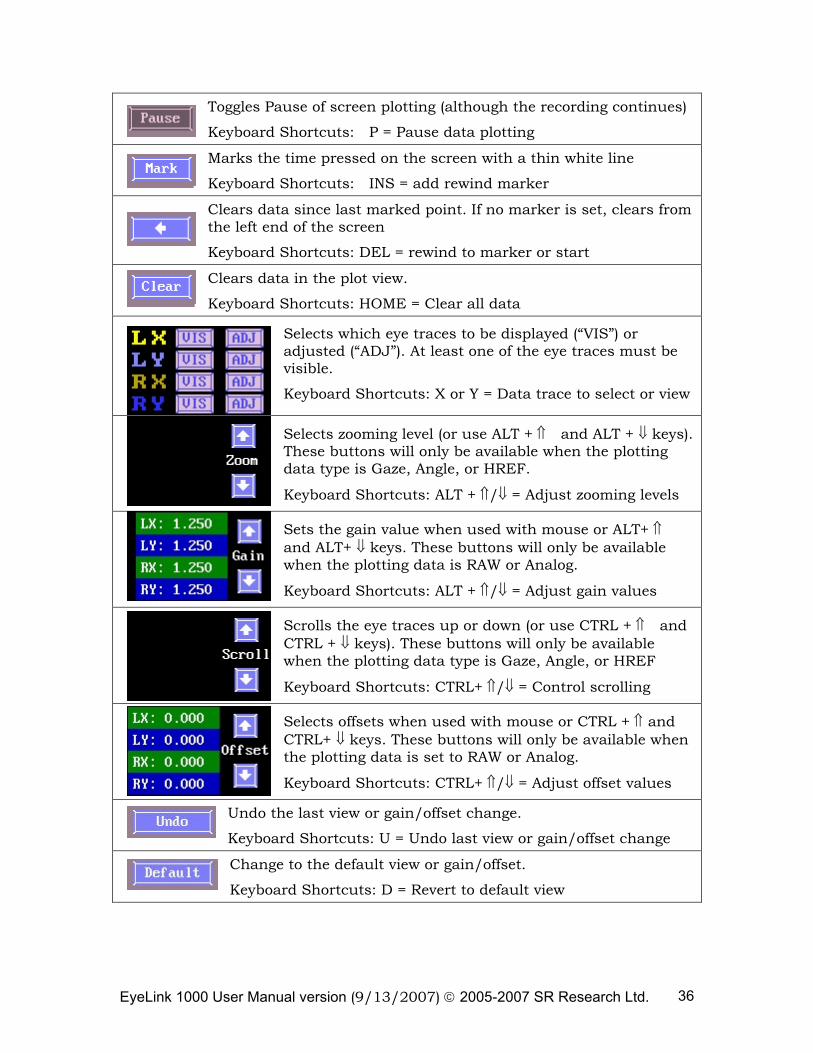
Toggles Pause of screen plotting (although the recording continues)
Keyboard Shortcuts: P = Pause data plotting
Marks the time pressed on the screen with a thin white line
Keyboard Shortcuts: INS = add rewind marker
Clears data since last marked point. If no marker is set, clears from the left end of the screen
Keyboard Shortcuts: DEL = rewind to marker or start
Clears data in the plot view.
Keyboard Shortcuts: HOME = Clear all data
Selects which eye traces to be displayed (“VIS”) or adjusted (“ADJ”). At least one of the eye traces must be visible.
Keyboard Shortcuts: X or Y = Data trace to select or view
Selects zooming level (or use ALT + ⇑ and ALT + ⇓ keys). These buttons will only be available when the plotting data type is Gaze, Angle, or HREF.
Keyboard Shortcuts: ALT + ⇑/⇓ = Adjust zooming levels
Sets the gain value when used with mouse or ALT+ ⇑ and ALT+ ⇓ keys. These buttons will only be available when the plotting data is RAW or Analog.
Keyboard Shortcuts: ALT + ⇑/⇓ = Adjust gain values
Scrolls the eye traces up or down (or use CTRL + ⇑ and CTRL + ⇓ keys). These buttons will only be available when the plotting data type is Gaze, Angle, or HREF
Keyboard Shortcuts: CTRL+ ⇑/⇓ = Control scrolling
Selects offsets when used with mouse or CTRL + ⇑ and CTRL+ ⇓ keys. These buttons will only be available when the plotting data is set to RAW or Analog.
Keyboard Shortcuts: CTRL+ ⇑/⇓ = Adjust offset values
Undo the last view or gain/offset change.
Keyboard Shortcuts: U = Undo last view or gain/offset change
Change to the default view or gain/offset.
Keyboard Shortcuts: D = Revert to default view
EyeLink 1000 User Manual version (9/13/2007) © 2005-2007 SR Research Ltd. 37
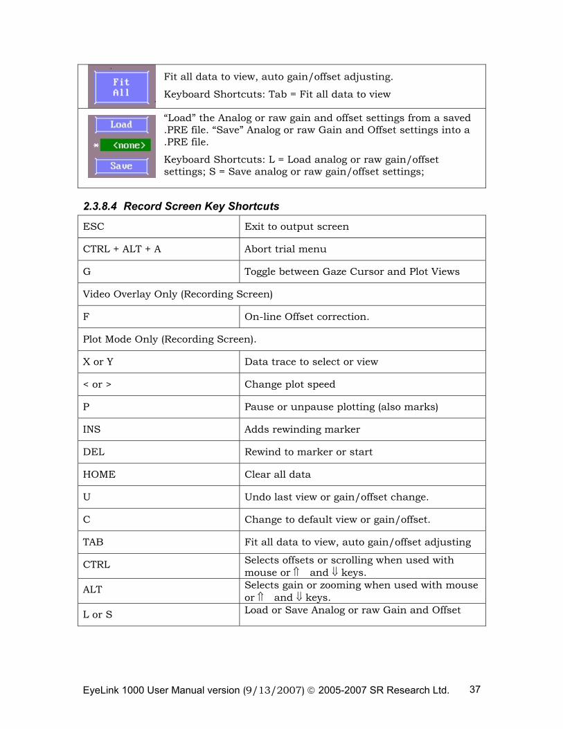
Fit all data to view, auto gain/offset adjusting.
Keyboard Shortcuts: Tab = Fit all data to view
“Load” the Analog or raw gain and offset settings from a saved .PRE file. “Save” Analog or raw Gain and Offset settings into a .PRE file.
Keyboard Shortcuts: L = Load analog or raw gain/offset settings; S = Save analog or raw gain/offset settings;
2.3.8.4 Record Screen Key Shortcuts
ESC Exit to output screen
CTRL + ALT + A Abort trial menu
G Toggle between Gaze Cursor and Plot Views
Video Overlay Only (Recording Screen)
F On-line Offset correction.
Plot Mode Only (Recording Screen).
X or Y Data trace to select or view
< or > Change plot speed
P Pause or unpause plotting (also marks)
INS Adds rewinding marker
DEL Rewind to marker or start
HOME Clear all data
U Undo last view or gain/offset change.
C Change to default view or gain/offset.
TAB Fit all data to view, auto gain/offset adjusting
CTRL Selects offsets or scrolling when used with mouse or ⇑ and ⇓ keys.
ALT Selects gain or zooming when used with mouse or ⇑ and ⇓ keys.
L or S Load or Save Analog or raw Gain and Offset
EyeLink 1000 User Manual version (9/13/2007) © 2005-2007 SR Research Ltd. 38
2.3.8.5 Example Gain and Offset Adjustments
Imagine a simple saccade task which displays a target along the horizontal meridian (left, center, right); you plan to send out -4 volt output when the subject fixates on a target appearing on the left end of the display and +4 volts when the subject fixates on the target on the right end.
1) Go to the Set Option screens. Set the “Record View” as “Plotting” and “Plot” data type as “Analog”. If you don’t have an analog card installed on the EyeLink Host PC, set the “Plot” data type to “RAW”.
2) Start the EyeLink recording. Present three targets at the left-end, right-end, and center of the screen, each for 5 seconds and instruct the subject to fixate on the targets as stably and precisely as possible. (If you do not have a program ready, you may mark the target positions on a cardboard and use the cardboard as the display screen.)
3) Click on the “Pause” button to pause display sweeping. Make sure that only the “X Sel” button is selected.
4) Click at the blank space next to the graph. A green marker will appear at intended value. For the ease of adjustments, you may set that point close to center of the left- and right-eye traces. Also note that a white bar at the right end of the graph. This bar sets the upper and lower bounds for gain and offset adjusts.
5) To adjust the gain of eye traces, place the mouse cursor outside of the regions bounds by the white bar. Drag the mouse up or down until the span of the upper and lower eye traces spans 8 volts. You will notice that both the gain and offset values are updated when you drag the mouse up or down.
6) Now, place the mouse cursor in the regions bounds by the white bar. Drag the mouse up or down until the top of the eye trace is aligned with 4 volts and bottom of the eye trace is aligned with -4 volts. Repeat steps 5) and 6) for fine tuning.
7) Once you are happy with the adjustments, don’t forget to unselect the “SEL” buttons on the “Adjust” button so that you will not accidentally touch the adjustments.
8) Now your “Calibration” is done. Click on the “Pause” button to continue recording.
EyeLink 1000 User Manual version (9/13/2007) © 2005-2007 SR Research Ltd. 39
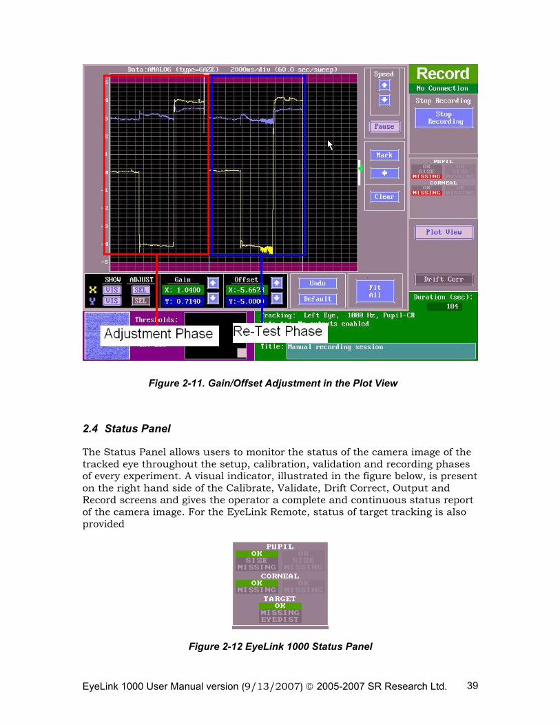
Figure 2-11. Gain/Offset Adjustment in the Plot View
2.4 Status Panel
The Status Panel allows users to monitor the status of the camera image of the tracked eye throughout the setup, calibration, validation and recording phases of every experiment. A visual indicator, illustrated in the figure below, is present on the right hand side of the Calibrate, Validate, Drift Correct, Output and Record screens and gives the operator a complete and continuous status report of the camera image. For the EyeLink Remote, status of target tracking is also provided
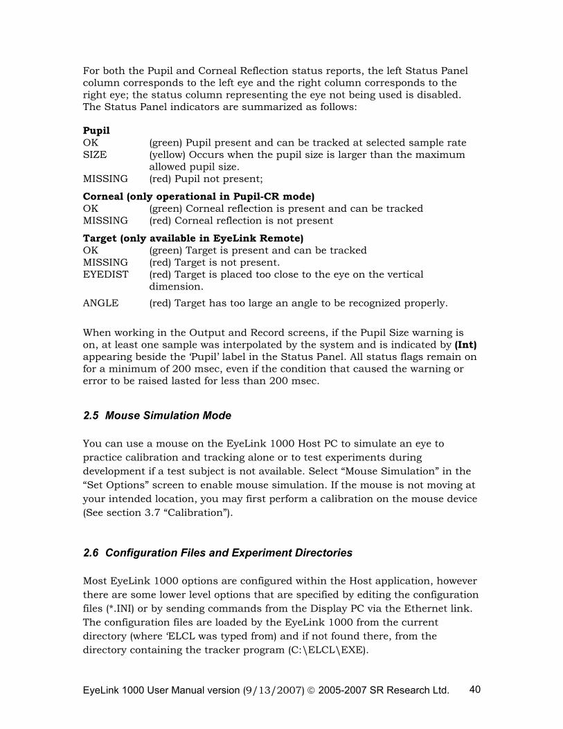
Figure 2-12 EyeLink 1000 Status Panel
EyeLink 1000 User Manual version (9/13/2007) © 2005-2007 SR Research Ltd. 40
For both the Pupil and Corneal Reflection status reports, the left Status Panel column corresponds to the left eye and the right column corresponds to the right eye; the status column representing the eye not being used is disabled. The Status Panel indicators are summarized as follows: Pupil OK (green) Pupil present and can be tracked at selected sample rate SIZE (yellow) Occurs when the pupil size is larger than the maximum
allowed pupil size. MISSING (red) Pupil not present; Corneal (only operational in Pupil-CR mode) OK (green) Corneal reflection is present and can be tracked MISSING (red) Corneal reflection is not present Target (only available in EyeLink Remote) OK (green) Target is present and can be tracked MISSING (red) Target is not present. EYEDIST (red) Target is placed too close to the eye on the vertical
dimension.
ANGLE (red) Target has too large an angle to be recognized properly. When working in the Output and Record screens, if the Pupil Size warning is on, at least one sample was interpolated by the system and is indicated by (Int) appearing beside the ‘Pupil’ label in the Status Panel. All status flags remain on for a minimum of 200 msec, even if the condition that caused the warning or error to be raised lasted for less than 200 msec.
2.5 Mouse Simulation Mode
You can use a mouse on the EyeLink 1000 Host PC to simulate an eye to practice calibration and tracking alone or to test experiments during development if a test subject is not available. Select “Mouse Simulation” in the “Set Options” screen to enable mouse simulation. If the mouse is not moving at your intended location, you may first perform a calibration on the mouse device (See section 3.7 “Calibration”).
2.6 Configuration Files and Experiment Directories
Most EyeLink 1000 options are configured within the Host application, however there are some lower level options that are specified by editing the configuration files (*.INI) or by sending commands from the Display PC via the Ethernet link. The configuration files are loaded by the EyeLink 1000 from the current directory (where ‘ELCL was typed from) and if not found there, from the directory containing the tracker program (C:\ELCL\EXE).
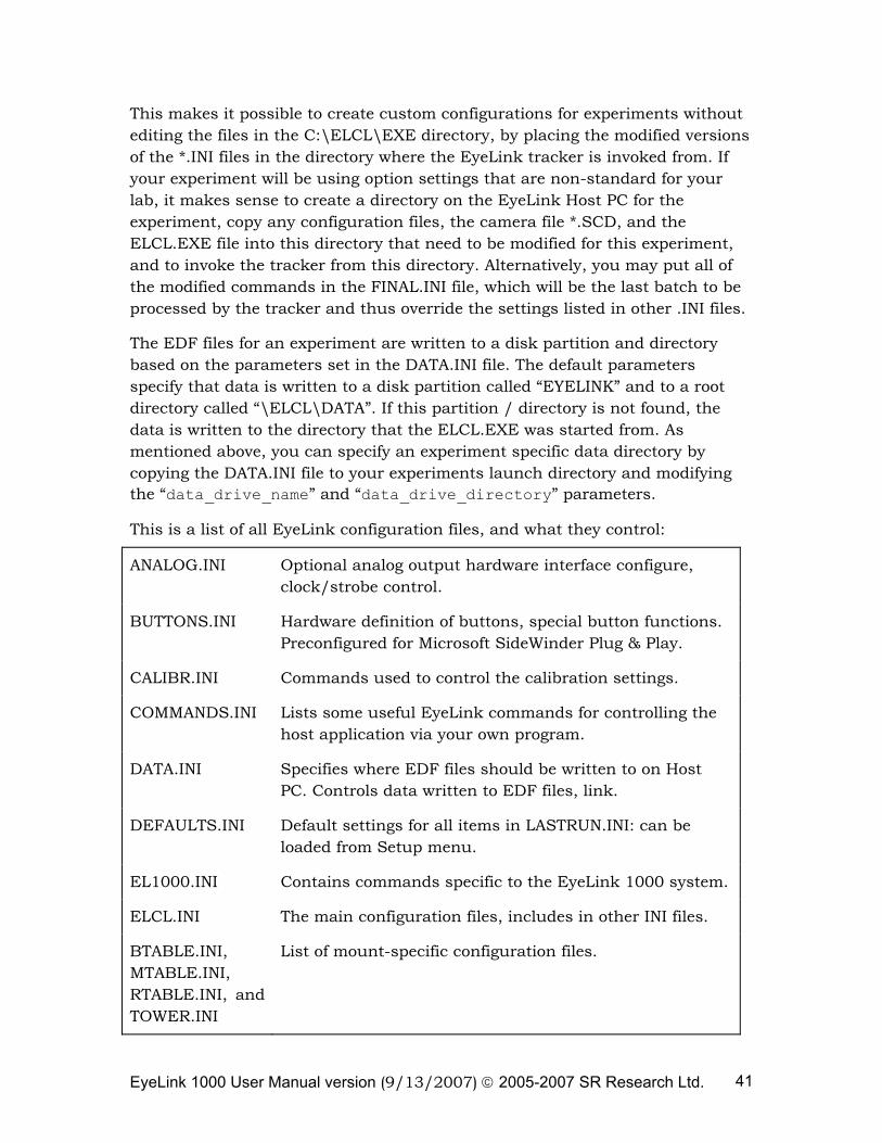
EyeLink 1000 User Manual version (9/13/2007) © 2005-2007 SR Research Ltd. 41
This makes it possible to create custom configurations for experiments without editing the files in the C:\ELCL\EXE directory, by placing the modified versions of the *.INI files in the directory where the EyeLink tracker is invoked from. If your experiment will be using option settings that are non-standard for your lab, it makes sense to create a directory on the EyeLink Host PC for the experiment, copy any configuration files, the camera file *.SCD, and the ELCL.EXE file into this directory that need to be modified for this experiment, and to invoke the tracker from this directory. Alternatively, you may put all of the modified commands in the FINAL.INI file, which will be the last batch to be processed by the tracker and thus override the settings listed in other .INI files.
The EDF files for an experiment are written to a disk partition and directory based on the parameters set in the DATA.INI file. The default parameters specify that data is written to a disk partition called “EYELINK” and to a root directory called “\ELCL\DATA”. If this partition / directory is not found, the data is written to the directory that the ELCL.EXE was started from. As mentioned above, you can specify an experiment specific data directory by copying the DATA.INI file to your experiments launch directory and modifying the “data_drive_name” and “data_drive_directory” parameters.
This is a list of all EyeLink configuration files, and what they control:
ANALOG.INI Optional analog output hardware interface configure, clock/strobe control.
BUTTONS.INI Hardware definition of buttons, special button functions. Preconfigured for Microsoft SideWinder Plug & Play.
CALIBR.INI Commands used to control the calibration settings.
COMMANDS.INI Lists some useful EyeLink commands for controlling the host application via your own program.
DATA.INI Specifies where EDF files should be written to on Host PC. Controls data written to EDF files, link.
DEFAULTS.INI Default settings for all items in LASTRUN.INI: can be loaded from Setup menu.
EL1000.INI Contains commands specific to the EyeLink 1000 system.
ELCL.INI The main configuration files, includes in other INI files.
BTABLE.INI, MTABLE.INI, RTABLE.INI, and TOWER.INI
List of mount-specific configuration files.
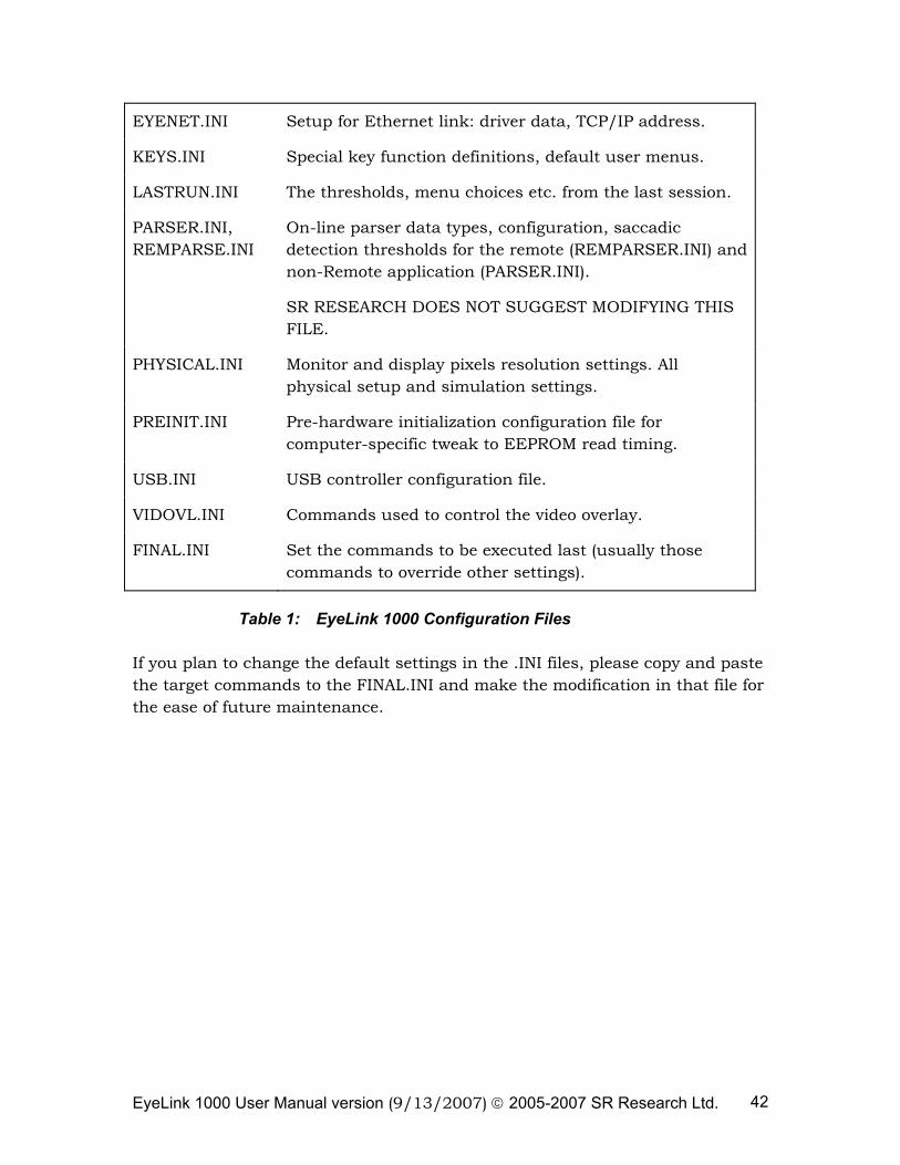
EyeLink 1000 User Manual version (9/13/2007) © 2005-2007 SR Research Ltd. 42
EYENET.INI Setup for Ethernet link: driver data, TCP/IP address.
KEYS.INI Special key function definitions, default user menus.
LASTRUN.INI The thresholds, menu choices etc. from the last session.
PARSER.INI, REMPARSE.INI
On-line parser data types, configuration, saccadic detection thresholds for the remote (REMPARSER.INI) and non-Remote application (PARSER.INI).
SR RESEARCH DOES NOT SUGGEST MODIFYING THIS FILE.
PHYSICAL.INI Monitor and display pixels resolution settings. All physical setup and simulation settings.
PREINIT.INI Pre-hardware initialization configuration file for computer-specific tweak to EEPROM read timing.
USB.INI USB controller configuration file.
VIDOVL.INI Commands used to control the video overlay.
FINAL.INI Set the commands to be executed last (usually those commands to override other settings).
Table 1: EyeLink 1000 Configuration Files
If you plan to change the default settings in the .INI files, please copy and paste the target commands to the FINAL.INI and make the modification in that file for the ease of future maintenance.
EyeLink 1000 User Manual version (9/13/2007) © 2005-2007 SR Research Ltd. 43
3. An EyeLink 1000 Tutorial: Running an Experiment
The following tutorial will demonstrate and test the EyeLink 1000 system, assuming that you have already arranged a proper layout of the EyeLink 1000 equipment and configured PHYSICAL.INI for your setup (see Section 1.1 “Suggested Equipment Layout” and Section 5 “Final Installation steps” of the “EyeLink 1000 Installation Guide” document). A summary of the setup procedure can be found at the end of the discussion (“3.13 EyeLink 1000 Setup Summary”). This section leads you through a straightforward subject setup and pupil – corneal reflection eye-tracking demonstration. For the easiest setup, you should select a subject for the test that can sit still when required, and does not have eyeglasses. Once comfortable on these subjects, you can tackle more difficult setup problems.
During the session description we take the opportunity to discuss many important aspects of system use. These may make the setup appear long, but a practiced experimenter can set up a subject in less than five minutes, including calibration and validation.
If the EyeLink host software is not yet running on the Host PC, start it by typing
CD C:\ELCL\EXE ↵
ELCL ↵
IMPORTANT: Remember to exit the EyeLink software by pressing the key combination CTRL+ALT+Q. Do not switch off the computer while running the EyeLink 1000 software, as data may be lost.
Now start a simple example application on the Display PC by selecting
Start->Programs -> SR Research -> EyeLink -> TRACK.EXE.
When TRACK starts, a copyright message will appear on the Display PC, and the status message (at the top right) should read “TCP/IP Link Open” on the Host PC.
A dialog will appear on the Display PC asking you to enter a Track EDF file name. Enter “TEST” (without the quotes “ ”).
Once TRACK is running, control is either from the Host PC or Display PC keyboard, and the application will reflect the state of the EyeLink 1000 software by drawing appropriate graphics on the Display PC. The advantage of the Display PC based control is that it allows the operator to work near the subject, or for self-setup. We will perform most of the EyeLink 1000 setup by using the Host PC keyboard.
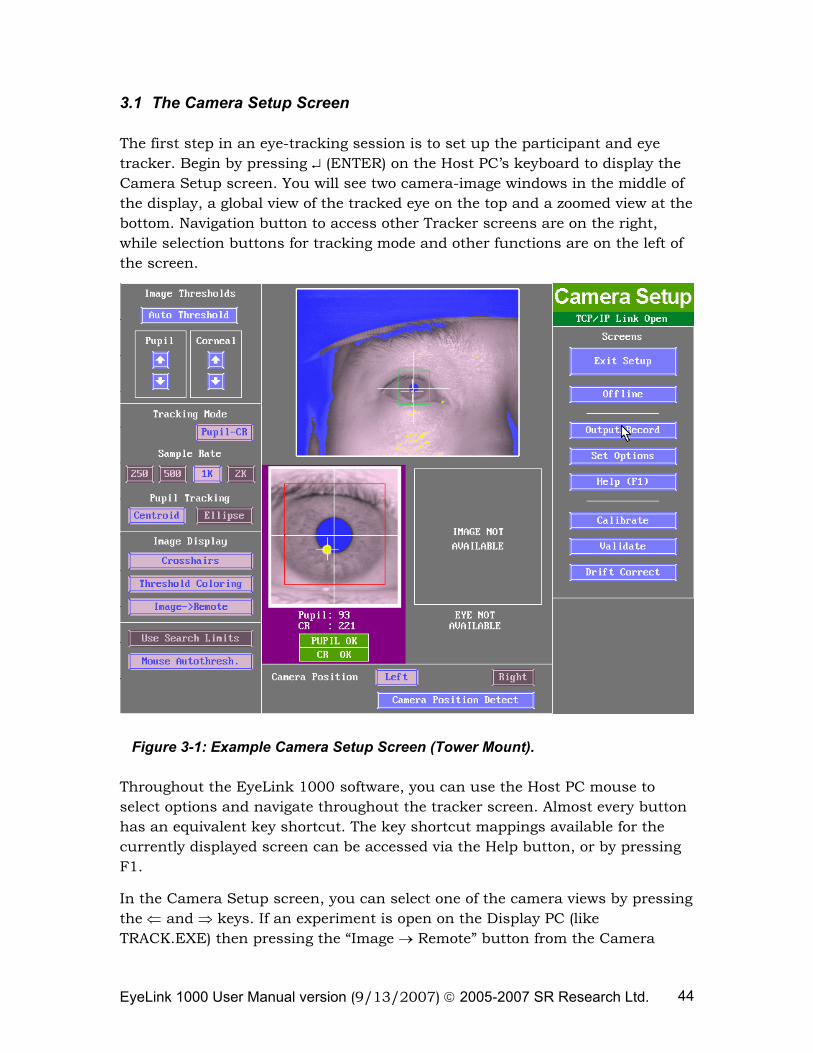
EyeLink 1000 User Manual version (9/13/2007) © 2005-2007 SR Research Ltd. 44
3.1 The Camera Setup Screen
The first step in an eye-tracking session is to set up the participant and eye tracker. Begin by pressing ↵ (ENTER) on the Host PC’s keyboard to display the Camera Setup screen. You will see two camera-image windows in the middle of the display, a global view of the tracked eye on the top and a zoomed view at the bottom. Navigation button to access other Tracker screens are on the right, while selection buttons for tracking mode and other functions are on the left of the screen.
Figure 3-1: Example Camera Setup Screen (Tower Mount).
Throughout the EyeLink 1000 software, you can use the Host PC mouse to select options and navigate throughout the tracker screen. Almost every button has an equivalent key shortcut. The key shortcut mappings available for the currently displayed screen can be accessed via the Help button, or by pressing F1.
In the Camera Setup screen, you can select one of the camera views by pressing the ⇐ and ⇒ keys. If an experiment is open on the Display PC (like TRACK.EXE) then pressing the “Image → Remote” button from the Camera
EyeLink 1000 User Manual version (9/13/2007) © 2005-2007 SR Research Ltd. 45
Setup screen will start displaying an image of the selected camera on the Display PC’s monitor.
3.2 Participant Setup
To practice setting up the camera, you will need a subject. If none is available, you can practice this part of the procedure on yourself. It is actually easier to practice on yourself first, but be sure to repeat with several subjects later. Because all keys on the subject keyboard are sent to the EyeLink software by TRACK, you can practice calibration and observe your tracked eye-position too. Since no menus appear on the Display PC, you will have to be able to see the Host PC display as well.
NOTE: Ideally, to prevent small drifts in thresholds, EyeLink 1000 electronics should be powered for about 5 minutes before recording.
The EyeLink 1000 has three mount and camera combinations: Tower Mount, Desktop Mount (Camera Level), and Desktop Mount (Camera Angled). Using these hardware combinations there are several different software modes: Monocular recording can be achieved with each hardware configuration, binocular recording is available when the camera is angled, and the EyeLink Remote mode allows monocular recording without head stabilization.
Depending on the license of your system and the requirements of your application, you will need to choose one of the above recording modes.
Please continue with one of the following participant setup tutorials:
Highly Accurate, Wide Field-of-View Monocular Recording 3.2.1 “Tower Mount Participant Setup, Monocular”
Highly Accurate, Chin and Forehead Rest Monocular Recording 3.2.2 “Desktop Mount (Level) Participant Setup, Monocular”
Highly Accurate, Chin and Forehead Rest Binocular or Monocular Recording 3.2.3 “Desktop Mount (Angled) Participant Setup, Binocular”
Accurate Monocular Recording Without Head Stabilization 3.2.4 “EyeLink Remote Participant Setup”
3.2.1 Tower Mount Participant Setup, Monocular
NOTE: Please check the height of the EyeLink 1000 tower before having a subject seated - ideally this should have the top of the display at about the same height as the forehead rest. The tower height adjustment should only
EyeLink 1000 User Manual version (9/13/2007) © 2005-2007 SR Research Ltd. 46
need to be done during initial system setup and not on a participant-to-participant basis.
Check the position of the eye selection knob on the tracker tower to see whether this matches the eye selection on the Camera Setup screen. Loosen the knob (turning counterclockwise), move the selection knob to the left if you plan to track the left eye and to the right if you plan to track the right eye, and then tighten the knob. Click on the “Camera Position Detect” button on the Camera Setup screen to check whether the correct eye is highlighted. If the eye highlighted on the Camera Setup screen does not match the eye selection knob position on the tracker device, you should ensure that the two illuminator cables that come out of the left side of the head support tower are connected properly to the left side of the EyeLink 1000 high-speed camera: the cable marked with “R” should be plugged to the port marked with an ‘R’ and the one with “L” to the remaining port.
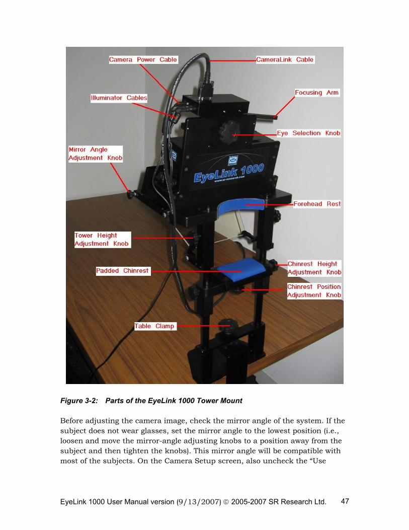
EyeLink 1000 User Manual version (9/13/2007) © 2005-2007 SR Research Ltd. 47
Figure 3-2: Parts of the EyeLink 1000 Tower Mount
Before adjusting the camera image, check the mirror angle of the system. If the subject does not wear glasses, set the mirror angle to the lowest position (i.e., loosen and move the mirror-angle adjusting knobs to a position away from the subject and then tighten the knobs). This mirror angle will be compatible with most of the subjects. On the Camera Setup screen, also uncheck the “Use
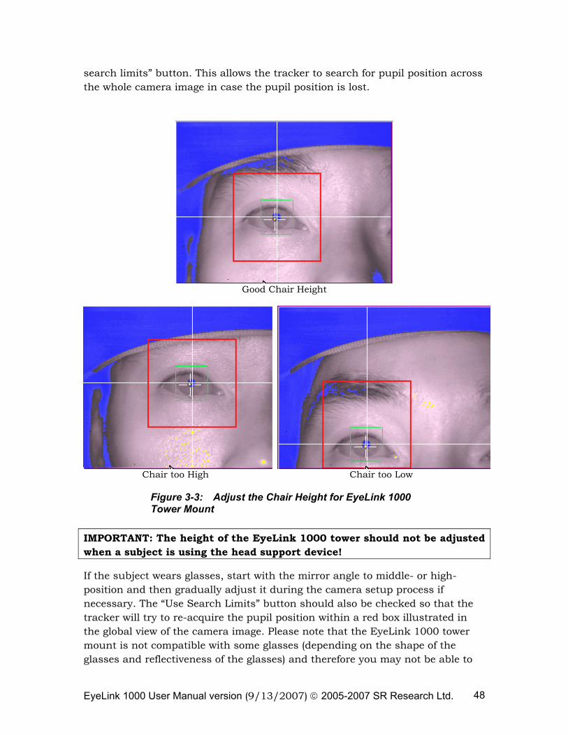
EyeLink 1000 User Manual version (9/13/2007) © 2005-2007 SR Research Ltd. 48
search limits” button. This allows the tracker to search for pupil position across the whole camera image in case the pupil position is lost.
Good Chair Height
Chair too High Chair too Low
Figure 3-3: Adjust the Chair Height for EyeLink 1000 Tower Mount
IMPORTANT: The height of the EyeLink 1000 tower should not be adjusted when a subject is using the head support device!
If the subject wears glasses, start with the mirror angle to middle- or high-position and then gradually adjust it during the camera setup process if necessary. The “Use Search Limits” button should also be checked so that the tracker will try to re-acquire the pupil position within a red box illustrated in the global view of the camera image. Please note that the EyeLink 1000 tower mount is not compatible with some glasses (depending on the shape of the glasses and reflectiveness of the glasses) and therefore you may not be able to
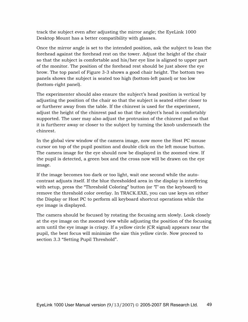
EyeLink 1000 User Manual version (9/13/2007) © 2005-2007 SR Research Ltd. 49
track the subject even after adjusting the mirror angle; the EyeLink 1000 Desktop Mount has a better compatibility with glasses.
Once the mirror angle is set to the intended position, ask the subject to lean the forehead against the forehead rest on the tower. Adjust the height of the chair so that the subject is comfortable and his/her eye line is aligned to upper part of the monitor. The position of the forehead rest should be just above the eye brow. The top panel of Figure 3-3 shows a good chair height. The bottom two panels shows the subject is seated too high (bottom-left panel) or too low (bottom-right panel).
The experimenter should also ensure the subject’s head position is vertical by adjusting the position of the chair so that the subject is seated either closer to or furtherer away from the table. If the chinrest is used for the experiment, adjust the height of the chinrest pad so that the subject’s head is comfortably supported. The user may also adjust the protrusion of the chinrest pad so that it is furtherer away or closer to the subject by turning the knob underneath the chinrest.
In the global view window of the camera image, now move the Host PC mouse cursor on top of the pupil position and double click on the left mouse button. The camera image for the eye should now be displayed in the zoomed view. If the pupil is detected, a green box and the cross now will be drawn on the eye image.
If the image becomes too dark or too light, wait one second while the auto-contrast adjusts itself. If the blue thresholded area in the display is interfering with setup, press the “Threshold Coloring” button (or ‘T’ on the keyboard) to remove the threshold color overlay. In TRACK.EXE, you can use keys on either the Display or Host PC to perform all keyboard shortcut operations while the eye image is displayed.
The camera should be focused by rotating the focusing arm slowly. Look closely at the eye image on the zoomed view while adjusting the position of the focusing arm until the eye image is crispy. If a yellow circle (CR signal) appears near the pupil, the best focus will minimize the size this yellow circle. Now proceed to section 3.3 “Setting Pupil Threshold”.
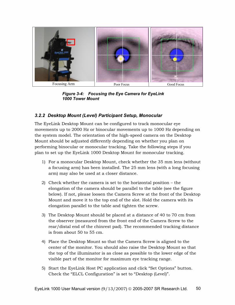
EyeLink 1000 User Manual version (9/13/2007) © 2005-2007 SR Research Ltd. 50
Focusing Arm Poor Focus Good Focus
Figure 3-4: Focusing the Eye Camera for EyeLink 1000 Tower Mount
3.2.2 Desktop Mount (Level) Participant Setup, Monocular
The EyeLink Desktop Mount can be configured to track monocular eye movements up to 2000 Hz or binocular movements up to 1000 Hz depending on the system model. The orientation of the high-speed camera on the Desktop Mount should be adjusted differently depending on whether you plan on performing binocular or monocular tracking. Take the following steps if you plan to set up the EyeLink 1000 Desktop Mount for monocular tracking.
1) For a monocular Desktop Mount, check whether the 35 mm lens (without a focusing arm) has been installed. The 25 mm lens (with a long focusing arm) may also be used at a closer distance.
2) Check whether the camera is set to the horizontal position – the elongation of the camera should be parallel to the table (see the figure below). If not, please loosen the Camera Screw at the front of the Desktop Mount and move it to the top end of the slot. Hold the camera with its elongation parallel to the table and tighten the screw.
3) The Desktop Mount should be placed at a distance of 40 to 70 cm from the observer (measured from the front end of the Camera Screw to the rear/distal end of the chinrest pad). The recommended tracking distance is from about 50 to 55 cm.
4) Place the Desktop Mount so that the Camera Screw is aligned to the center of the monitor. You should also raise the Desktop Mount so that the top of the illuminator is as close as possible to the lower edge of the visible part of the monitor for maximum eye tracking range.
5) Start the EyeLink Host PC application and click “Set Options” button. Check the “ELCL Configuration” is set to “Desktop (Level)”.
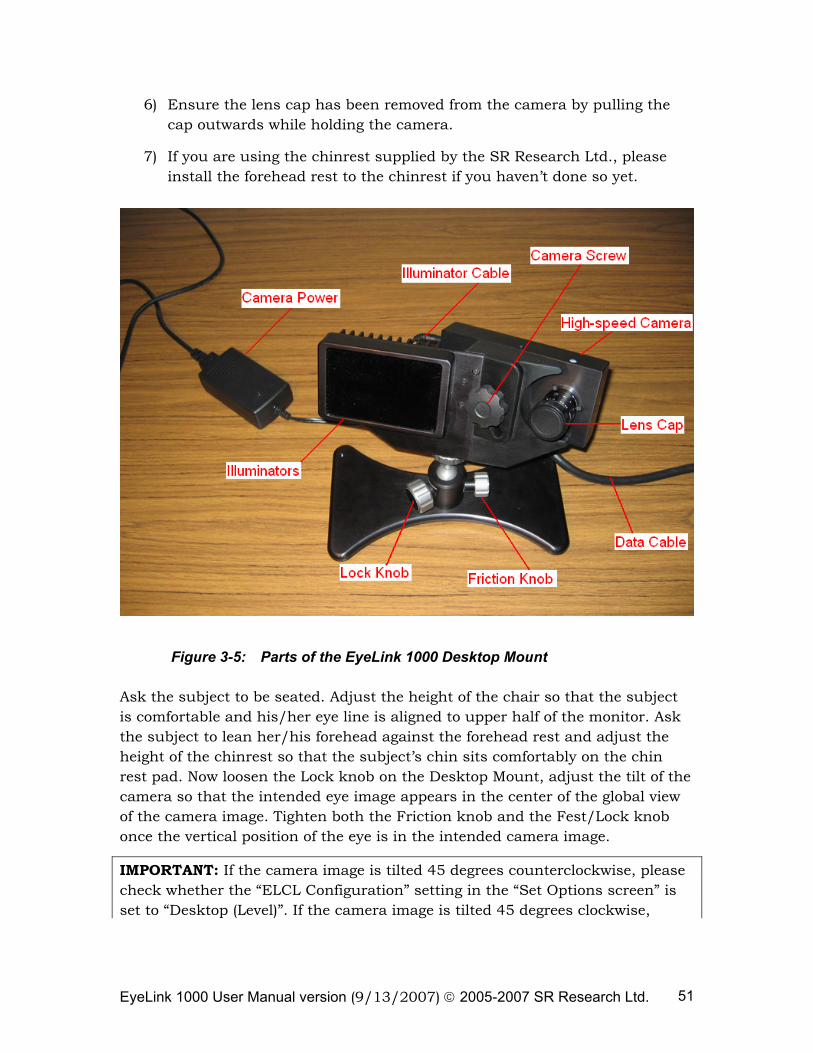
EyeLink 1000 User Manual version (9/13/2007) © 2005-2007 SR Research Ltd. 51
6) Ensure the lens cap has been removed from the camera by pulling the cap outwards while holding the camera.
7) If you are using the chinrest supplied by the SR Research Ltd., please install the forehead rest to the chinrest if you haven’t done so yet.
Figure 3-5: Parts of the EyeLink 1000 Desktop Mount
Ask the subject to be seated. Adjust the height of the chair so that the subject is comfortable and his/her eye line is aligned to upper half of the monitor. Ask the subject to lean her/his forehead against the forehead rest and adjust the height of the chinrest so that the subject’s chin sits comfortably on the chin rest pad. Now loosen the Lock knob on the Desktop Mount, adjust the tilt of the camera so that the intended eye image appears in the center of the global view of the camera image. Tighten both the Friction knob and the Fest/Lock knob once the vertical position of the eye is in the intended camera image.
IMPORTANT: If the camera image is tilted 45 degrees counterclockwise, please check whether the “ELCL Configuration” setting in the “Set Options screen” is set to “Desktop (Level)”. If the camera image is tilted 45 degrees clockwise,
EyeLink 1000 User Manual version (9/13/2007) © 2005-2007 SR Research Ltd. 52
check whether the camera is set to the horizontal position on the Desktop Mount.
In the global view window of the camera image, move the Host PC mouse cursor on top of the pupil position and double click on the left mouse button. The camera image for the eye should now be displayed in the zoomed view. If the pupil is detected, a green box and the cross now will be drawn on the eye image.
Please note that for most subjects, you will just need to adjust the height of the chinrest and chair to get the intended camera image, without changing the Desktop Mount settings. However, for subjects wearing glasses, depending on the shape and reflection of the glasses, you may need to make slight adjustments to the Desktop Mount (e.g., move the camera slightly left, right, forward or backward, or adjust the angle of the illuminator and camera) so that reflections from the glass will not interference with pupil acquisition. The left panel of the following figure illustrates a good camera setup whereas the reflections in the right panel block the pupil image, especially when the subject looks in the direction of the glass reflection.
Figure 3-6. Camera Setup with Subjects Wearing Glasses (the EyeLink 1000 Monocular Mount).
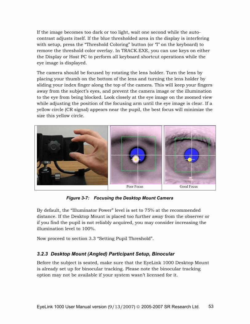
EyeLink 1000 User Manual version (9/13/2007) © 2005-2007 SR Research Ltd. 53
If the image becomes too dark or too light, wait one second while the auto-contrast adjusts itself. If the blue thresholded area in the display is interfering with setup, press the “Threshold Coloring” button (or ‘T’ on the keyboard) to remove the threshold color overlay. In TRACK.EXE, you can use keys on either the Display or Host PC to perform all keyboard shortcut operations while the eye image is displayed.
The camera should be focused by rotating the lens holder. Turn the lens by placing your thumb on the bottom of the lens and turning the lens holder by sliding your index finger along the top of the camera. This will keep your fingers away from the subject’s eyes, and prevent the camera image or the illumination to the eye from being blocked. Look closely at the eye image on the zoomed view while adjusting the position of the focusing arm until the eye image is clear. If a yellow circle (CR signal) appears near the pupil, the best focus will minimize the size this yellow circle.
Poor Focus Good Focus
Figure 3-7: Focusing the Desktop Mount Camera
By default, the “Illuminator Power” level is set to 75% at the recommended distance. If the Desktop Mount is placed too further away from the observer or if you find the pupil is not reliably acquired, you may consider increasing the illumination level to 100%.
Now proceed to section 3.3 “Setting Pupil Threshold”.
3.2.3 Desktop Mount (Angled) Participant Setup, Binocular
Before the subject is seated, make sure that the EyeLink 1000 Desktop Mount is already set up for binocular tracking. Please note the binocular tracking option may not be available if your system wasn’t licensed for it.
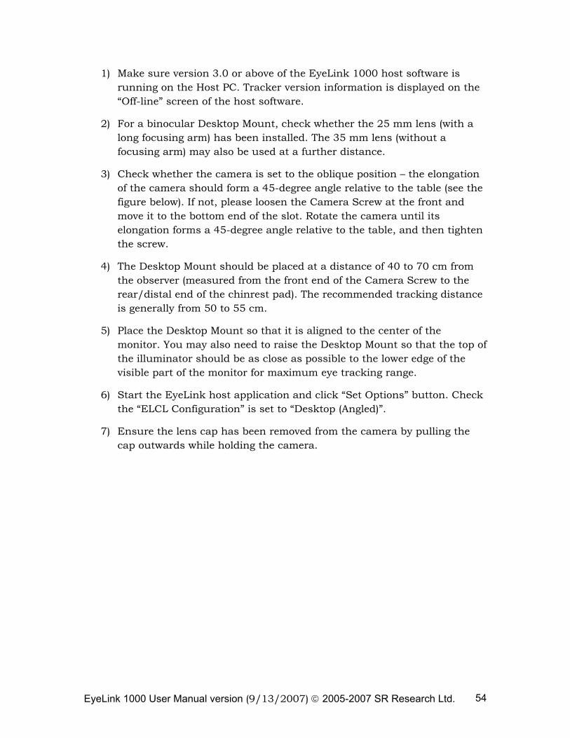
EyeLink 1000 User Manual version (9/13/2007) © 2005-2007 SR Research Ltd. 54
1) Make sure version 3.0 or above of the EyeLink 1000 host software is running on the Host PC. Tracker version information is displayed on the “Off-line” screen of the host software.
2) For a binocular Desktop Mount, check whether the 25 mm lens (with a long focusing arm) has been installed. The 35 mm lens (without a focusing arm) may also be used at a further distance.
3) Check whether the camera is set to the oblique position – the elongation of the camera should form a 45-degree angle relative to the table (see the figure below). If not, please loosen the Camera Screw at the front and move it to the bottom end of the slot. Rotate the camera until its elongation forms a 45-degree angle relative to the table, and then tighten the screw.
4) The Desktop Mount should be placed at a distance of 40 to 70 cm from the observer (measured from the front end of the Camera Screw to the rear/distal end of the chinrest pad). The recommended tracking distance is generally from 50 to 55 cm.
5) Place the Desktop Mount so that it is aligned to the center of the monitor. You may also need to raise the Desktop Mount so that the top of the illuminator should be as close as possible to the lower edge of the visible part of the monitor for maximum eye tracking range.
6) Start the EyeLink host application and click “Set Options” button. Check the “ELCL Configuration” is set to “Desktop (Angled)”.
7) Ensure the lens cap has been removed from the camera by pulling the cap outwards while holding the camera.
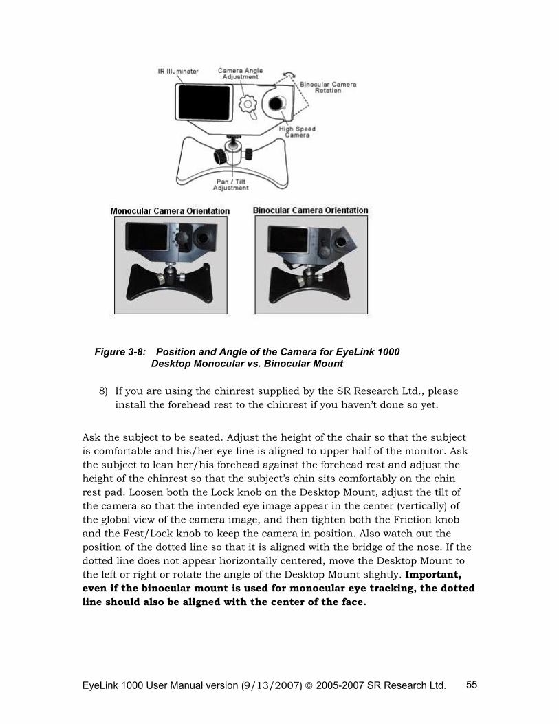
EyeLink 1000 User Manual version (9/13/2007) © 2005-2007 SR Research Ltd. 55
Figure 3-8: Position and Angle of the Camera for EyeLink 1000 Desktop Monocular vs. Binocular Mount
8) If you are using the chinrest supplied by the SR Research Ltd., please install the forehead rest to the chinrest if you haven’t done so yet.
Ask the subject to be seated. Adjust the height of the chair so that the subject is comfortable and his/her eye line is aligned to upper half of the monitor. Ask the subject to lean her/his forehead against the forehead rest and adjust the height of the chinrest so that the subject’s chin sits comfortably on the chin rest pad. Loosen both the Lock knob on the Desktop Mount, adjust the tilt of the camera so that the intended eye image appear in the center (vertically) of the global view of the camera image, and then tighten both the Friction knob and the Fest/Lock knob to keep the camera in position. Also watch out the position of the dotted line so that it is aligned with the bridge of the nose. If the dotted line does not appear horizontally centered, move the Desktop Mount to the left or right or rotate the angle of the Desktop Mount slightly. Important, even if the binocular mount is used for monocular eye tracking, the dotted line should also be aligned with the center of the face.
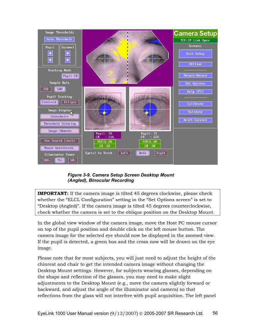
EyeLink 1000 User Manual version (9/13/2007) © 2005-2007 SR Research Ltd. 56
Figure 3-9. Camera Setup Screen Desktop Mount (Angled), Binocular Recording
IMPORTANT: If the camera image is tilted 45 degrees clockwise, please check whether the “ELCL Configuration” setting in the “Set Options screen” is set to “Desktop (Angled)”. If the camera image is tilted 45 degrees counterclockwise, check whether the camera is set to the oblique position on the Desktop Mount.
In the global view window of the camera image, move the Host PC mouse cursor on top of the pupil position and double click on the left mouse button. The camera image for the selected eye should now be displayed in the zoomed view. If the pupil is detected, a green box and the cross now will be drawn on the eye image.
Please note that for most subjects, you will just need to adjust the height of the chinrest and chair to get the intended camera image without changing the Desktop Mount settings. However, for subjects wearing glasses, depending on the shape and reflection of the glasses, you may need to make slight adjustments to the Desktop Mount (e.g., move the camera slightly forward or backward, and adjust the angle of the illuminator and camera) so that reflections from the glass will not interfere with pupil acquisition. The left panel
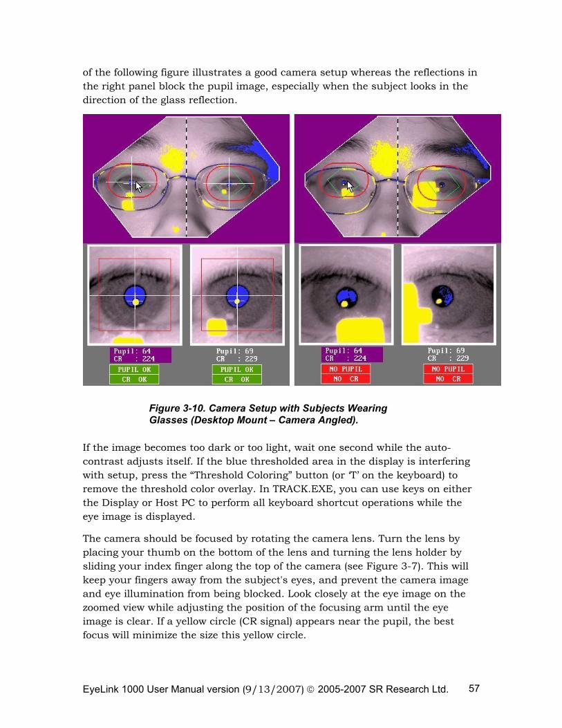
EyeLink 1000 User Manual version (9/13/2007) © 2005-2007 SR Research Ltd. 57
of the following figure illustrates a good camera setup whereas the reflections in the right panel block the pupil image, especially when the subject looks in the direction of the glass reflection.
Figure 3-10. Camera Setup with Subjects Wearing Glasses (Desktop Mount – Camera Angled).
If the image becomes too dark or too light, wait one second while the auto-contrast adjusts itself. If the blue thresholded area in the display is interfering with setup, press the “Threshold Coloring” button (or ‘T’ on the keyboard) to remove the threshold color overlay. In TRACK.EXE, you can use keys on either the Display or Host PC to perform all keyboard shortcut operations while the eye image is displayed.
The camera should be focused by rotating the camera lens. Turn the lens by placing your thumb on the bottom of the lens and turning the lens holder by sliding your index finger along the top of the camera (see Figure 3-7). This will keep your fingers away from the subject's eyes, and prevent the camera image and eye illumination from being blocked. Look closely at the eye image on the zoomed view while adjusting the position of the focusing arm until the eye image is clear. If a yellow circle (CR signal) appears near the pupil, the best focus will minimize the size this yellow circle.

EyeLink 1000 User Manual version (9/13/2007) © 2005-2007 SR Research Ltd. 58
By default, the “Illuminator Power” level is set to 75% at the recommended distance. If the Desktop Mount is placed too further away from the observer or if you find the pupil is not reliably acquired, you may consider increasing the illumination level to 100%. Now continue with section 3.3 “Setting Pupil Threshold”.
3.2.4 EyeLink Remote Participant Setup
The EyeLink Remote is designed for applications where a chin rest or head mount is not desirable or perhaps even possible (i.e., patient work, gerontology, children, etc.). The EyeLink Remote provides 500 Hz monocular tracking as well as 500 Hz head distance estimation via the use of a small target sticker placed on the participant’s forehead.
If your system is licensed to use the EyeLink Remote mode, take the following steps to set up the camera and perform image adjustments.
1) For the EyeLink Remote, affix the 16 mm lens (shipped standard with a short adjustable focus arm) to the high-speed camera.
2) Check that the camera is in the level position – the elongation of the camera should be parallel to the table and the upper surface of the camera aligns smoothly with the Desktop Mount, with the Camera Screw in the topmost position. If the camera is not in this position, loosen the Camera Screw at the front of the Desktop Mount and move it to the top end of the slot. Hold the camera with its elongation parallel to the table and its top surface flush with the mount, and tighten the screw. Dimples on the camera fit into projections on the mount to ensure that the camera is in the proper position. Plug in the illuminator cables and the power cable into the camera. Also make sure the CameraLink data cable coming from the Host PC (the end with a right-angle connector) has been connected to the back of the camera and tightly fastened with the thumb screws.
3) In addition to an active license (programmed in the hardware), the EyeLink Remote requires version 4.0 or later of the EyeLink 1000 host software which can be downloaded from the SR Research Support website (https://www.sr-support.com/forums/showthread.php?t=179). This can be done easily through Windows Explorer. Be sure to back up (e.g. duplicate) your existing host ELCL\EXE directory from the EYELINK hard drive partition before upgrading to the latest host software. You will need to copy the .SCD file for your camera from your old ELCL\EXE directory to the new ELCL\EXE directory. Should you accidentally destroy your .SCD file, a copy should be safely stored on the CDs you received with your EyeLink 1000.
EyeLink 1000 User Manual version (9/13/2007) © 2005-2007 SR Research Ltd. 59
4) The height of the Display PC monitor should be set so that when the participant is seated and looking straight ahead, they are looking vertically at the middle to top 75% of the monitor. Ideally the Desktop Mount should be about 60 cm from the subject’s eyes (this will translate into an eye-screen distance of about 70 cm, with the Desktop Mount placed right in front of the Display PC monitor with no extra space between them). The Camera Screw of the Desktop Mount should be aligned with the horizontal center of the monitor. For maximum eye tracking range, the Mount should be raised so that the top of the illuminator is parallel with, and as close as possible to, the lower edge of the visible part of the monitor without blocking the subject’s view of the screen. To keep the viewing distance relatively constant throughout a recording session, a comfortable, stable chair for the subject is recommended.
5) Start the Host PC application and go to the “Set Options” screen. If your system is licensed for remote eye tracking, you should now see “Remote (Level)” as one of the ELCL configuration options. Select “Remote (Level)” and then go to the Camera Setup screen.
6) Ensure the lens cap has been removed from the camera by pulling it outwards while holding the camera. A camera image should now be displayed on the global view of Camera Setup screen on the Host PC. Ask the subject to be seated. Adjust the height of the chair so that the subject is comfortable and his/her line of sight is to the upper half of the monitor. Loosen the Lock Knob on the Desktop Mount, adjust the tilt of the camera so that the image of the eye appears in the center of the global view of the camera image. Tighten both the Friction knob and the Fest/Lock Knob to ensure the camera stays in position.
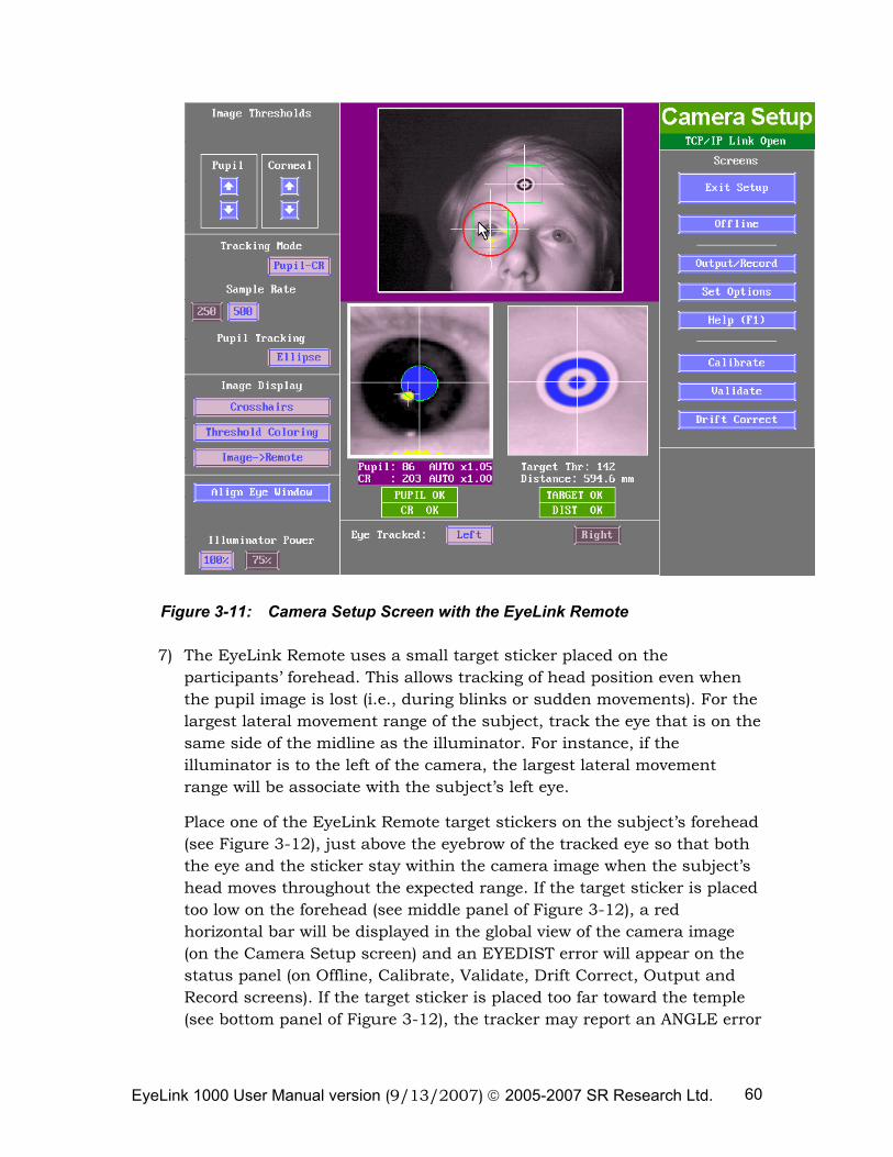
EyeLink 1000 User Manual version (9/13/2007) © 2005-2007 SR Research Ltd. 60
Figure 3-11: Camera Setup Screen with the EyeLink Remote
7) The EyeLink Remote uses a small target sticker placed on the participants’ forehead. This allows tracking of head position even when the pupil image is lost (i.e., during blinks or sudden movements). For the largest lateral movement range of the subject, track the eye that is on the same side of the midline as the illuminator. For instance, if the illuminator is to the left of the camera, the largest lateral movement range will be associate with the subject’s left eye.
Place one of the EyeLink Remote target stickers on the subject’s forehead (see Figure 3-12), just above the eyebrow of the tracked eye so that both the eye and the sticker stay within the camera image when the subject’s head moves throughout the expected range. If the target sticker is placed too low on the forehead (see middle panel of Figure 3-12), a red horizontal bar will be displayed in the global view of the camera image (on the Camera Setup screen) and an EYEDIST error will appear on the status panel (on Offline, Calibrate, Validate, Drift Correct, Output and Record screens). If the target sticker is placed too far toward the temple (see bottom panel of Figure 3-12), the tracker may report an ANGLE error
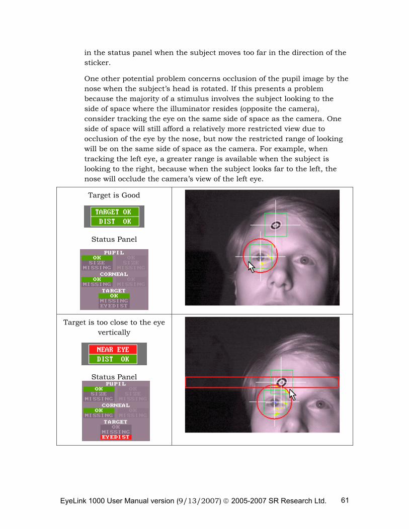
EyeLink 1000 User Manual version (9/13/2007) © 2005-2007 SR Research Ltd. 61
in the status panel when the subject moves too far in the direction of the sticker.
One other potential problem concerns occlusion of the pupil image by the nose when the subject’s head is rotated. If this presents a problem because the majority of a stimulus involves the subject looking to the side of space where the illuminator resides (opposite the camera), consider tracking the eye on the same side of space as the camera. One side of space will still afford a relatively more restricted view due to occlusion of the eye by the nose, but now the restricted range of looking will be on the same side of space as the camera. For example, when tracking the left eye, a greater range is available when the subject is looking to the right, because when the subject looks far to the left, the nose will occlude the camera’s view of the left eye.
Target is Good
Status Panel
Target is too close to the eye vertically
Status Panel
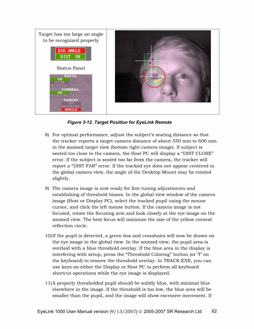
EyeLink 1000 User Manual version (9/13/2007) © 2005-2007 SR Research Ltd. 62
Target has too large an angle to be recognized properly
Status Panel
Figure 3-12. Target Position for EyeLink Remote
8) For optimal performance, adjust the subject’s seating distance so that the tracker reports a target-camera distance of about 550 mm to 600 mm in the zoomed target view (bottom right camera image). If subject is seated too close to the camera, the Host PC will display a “DIST CLOSE” error. If the subject is seated too far from the camera, the tracker will report a “DIST FAR” error. If the tracked eye does not appear centered in the global camera view, the angle of the Desktop Mount may be rotated slightly.
9) The camera image is now ready for fine tuning adjustments and establishing of threshold biases. In the global view window of the camera image (Host or Display PC), select the tracked pupil using the mouse cursor, and click the left mouse button. If the camera image is not focused, rotate the focusing arm and look closely at the eye image on the zoomed view. The best focus will minimize the size of the yellow corneal reflection circle.
10) If the pupil is detected, a green box and crosshairs will now be drawn on the eye image in the global view. In the zoomed view, the pupil area is overlaid with a blue threshold overlay. If the blue area in the display is interfering with setup, press the “Threshold Coloring” button (or ‘T’ on the keyboard) to remove the threshold overlay. In TRACK.EXE, you can use keys on either the Display or Host PC to perform all keyboard shortcut operations while the eye image is displayed.
11) A properly thresholded pupil should be solidly blue, with minimal blue elsewhere in the image. If the threshold is too low, the blue area will be smaller than the pupil, and the image will show excessive movement. If
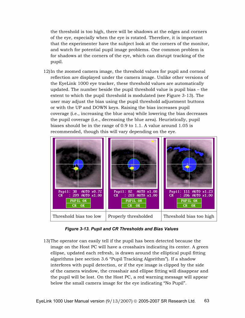
EyeLink 1000 User Manual version (9/13/2007) © 2005-2007 SR Research Ltd. 63
the threshold is too high, there will be shadows at the edges and corners of the eye, especially when the eye is rotated. Therefore, it is important that the experimenter have the subject look at the corners of the monitor, and watch for potential pupil image problems. One common problem is for shadows at the corners of the eye, which can disrupt tracking of the pupil.
12) In the zoomed camera image, the threshold values for pupil and corneal reflection are displayed under the camera image. Unlike other versions of the EyeLink 1000 eye tracker, these threshold values are automatically updated. The number beside the pupil threshold value is pupil bias – the extent to which the pupil threshold is modulated (see Figure 3-13). The user may adjust the bias using the pupil threshold adjustment buttons or with the UP and DOWN keys. Raising the bias increases pupil coverage (i.e., increasing the blue area) while lowering the bias decreases the pupil coverage (i.e., decreasing the blue area). Heuristically, pupil biases should be in the range of 0.9 to 1.1. A value around 1.05 is recommended, though this will vary depending on the eye.
Threshold bias too low Properly thresholded Threshold bias too high
Figure 3-13. Pupil and CR Thresholds and Bias Values
13) The operator can easily tell if the pupil has been detected because the image on the Host PC will have a crosshairs indicating its center. A green ellipse, updated each refresh, is drawn around the elliptical pupil fitting algorithms (see section 3.6 “Pupil Tracking Algorithm”). If a shadow interferes with pupil detection, or if the eye image is clipped by the side of the camera window, the crosshair and ellipse fitting will disappear and the pupil will be lost. On the Host PC, a red warning message will appear below the small camera image for the eye indicating “No Pupil”.
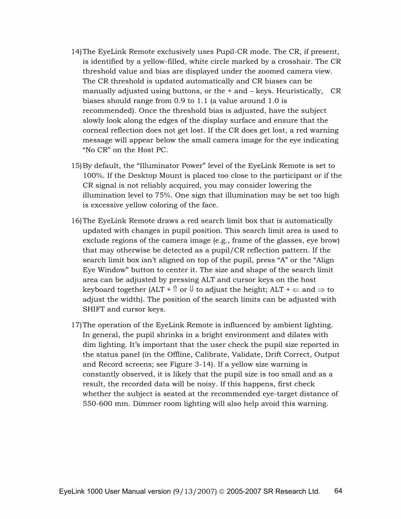
EyeLink 1000 User Manual version (9/13/2007) © 2005-2007 SR Research Ltd. 64
14) The EyeLink Remote exclusively uses Pupil-CR mode. The CR, if present, is identified by a yellow-filled, white circle marked by a crosshair. The CR threshold value and bias are displayed under the zoomed camera view. The CR threshold is updated automatically and CR biases can be manually adjusted using buttons, or the + and – keys. Heuristically, CR biases should range from 0.9 to 1.1 (a value around 1.0 is recommended). Once the threshold bias is adjusted, have the subject slowly look along the edges of the display surface and ensure that the corneal reflection does not get lost. If the CR does get lost, a red warning message will appear below the small camera image for the eye indicating “No CR” on the Host PC.
15) By default, the “Illuminator Power” level of the EyeLink Remote is set to 100%. If the Desktop Mount is placed too close to the participant or if the CR signal is not reliably acquired, you may consider lowering the illumination level to 75%. One sign that illumination may be set too high is excessive yellow coloring of the face.
16) The EyeLink Remote draws a red search limit box that is automatically updated with changes in pupil position. This search limit area is used to exclude regions of the camera image (e.g., frame of the glasses, eye brow) that may otherwise be detected as a pupil/CR reflection pattern. If the search limit box isn’t aligned on top of the pupil, press “A” or the “Align Eye Window” button to center it. The size and shape of the search limit area can be adjusted by pressing ALT and cursor keys on the host keyboard together (ALT + ⇑ or ⇓ to adjust the height; ALT + ⇐ and ⇒ to adjust the width). The position of the search limits can be adjusted with SHIFT and cursor keys.
17) The operation of the EyeLink Remote is influenced by ambient lighting. In general, the pupil shrinks in a bright environment and dilates with dim lighting. It’s important that the user check the pupil size reported in the status panel (in the Offline, Calibrate, Validate, Drift Correct, Output and Record screens; see Figure 3-14). If a yellow size warning is constantly observed, it is likely that the pupil size is too small and as a result, the recorded data will be noisy. If this happens, first check whether the subject is seated at the recommended eye-target distance of 550-600 mm. Dimmer room lighting will also help avoid this warning.
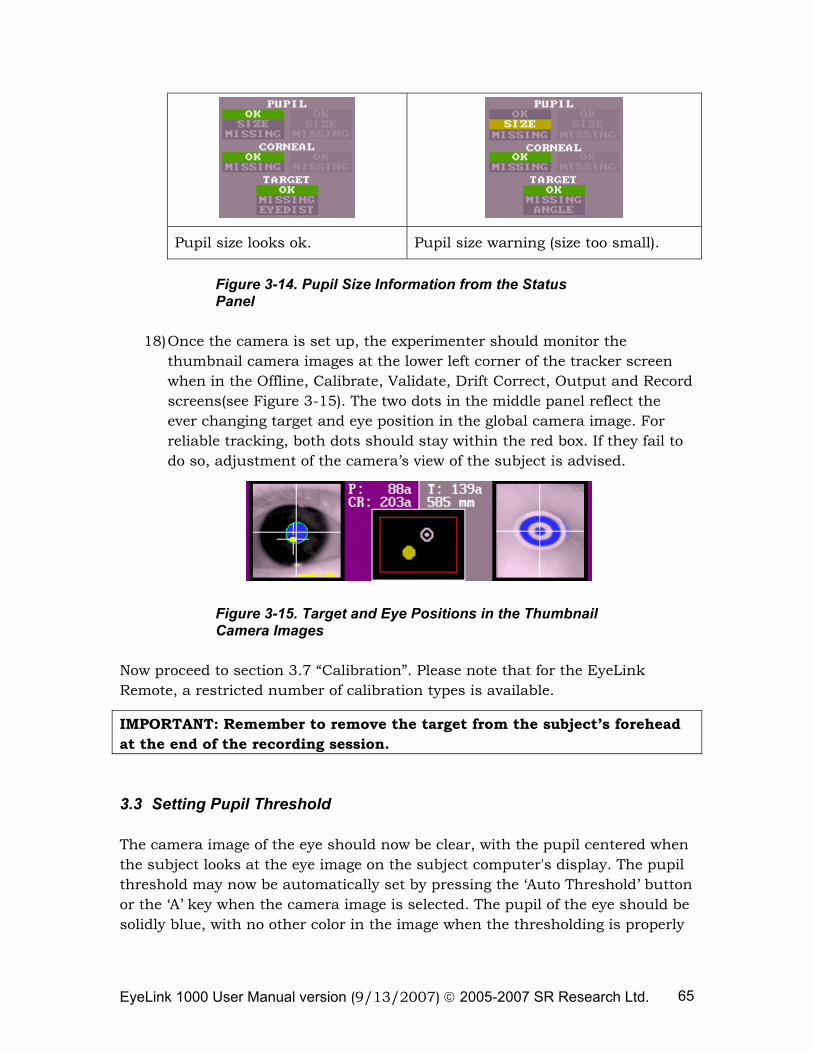
EyeLink 1000 User Manual version (9/13/2007) © 2005-2007 SR Research Ltd. 65
Pupil size looks ok. Pupil size warning (size too small).
Figure 3-14. Pupil Size Information from the Status Panel
18) Once the camera is set up, the experimenter should monitor the thumbnail camera images at the lower left corner of the tracker screen when in the Offline, Calibrate, Validate, Drift Correct, Output and Record screens(see Figure 3-15). The two dots in the middle panel reflect the ever changing target and eye position in the global camera image. For reliable tracking, both dots should stay within the red box. If they fail to do so, adjustment of the camera’s view of the subject is advised.
Figure 3-15. Target and Eye Positions in the Thumbnail Camera Images
Now proceed to section 3.7 “Calibration”. Please note that for the EyeLink Remote, a restricted number of calibration types is available.
IMPORTANT: Remember to remove the target from the subject’s forehead at the end of the recording session.
3.3 Setting Pupil Threshold
The camera image of the eye should now be clear, with the pupil centered when the subject looks at the eye image on the subject computer's display. The pupil threshold may now be automatically set by pressing the ‘Auto Threshold’ button or the ‘A’ key when the camera image is selected. The pupil of the eye should be solidly blue, with no other color in the image when the thresholding is properly
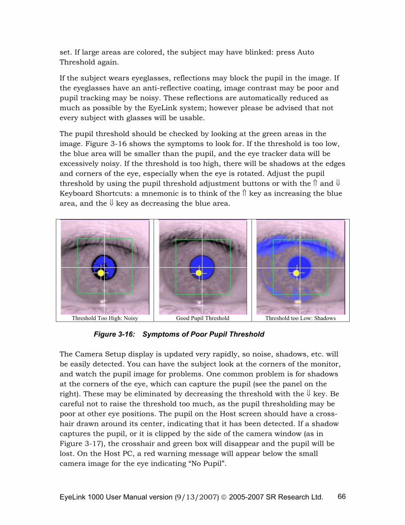
EyeLink 1000 User Manual version (9/13/2007) © 2005-2007 SR Research Ltd. 66
set. If large areas are colored, the subject may have blinked: press Auto Threshold again.
If the subject wears eyeglasses, reflections may block the pupil in the image. If the eyeglasses have an anti-reflective coating, image contrast may be poor and pupil tracking may be noisy. These reflections are automatically reduced as much as possible by the EyeLink system; however please be advised that not every subject with glasses will be usable.
The pupil threshold should be checked by looking at the green areas in the image. Figure 3-16 shows the symptoms to look for. If the threshold is too low, the blue area will be smaller than the pupil, and the eye tracker data will be excessively noisy. If the threshold is too high, there will be shadows at the edges and corners of the eye, especially when the eye is rotated. Adjust the pupil threshold by using the pupil threshold adjustment buttons or with the ⇑ and ⇓ Keyboard Shortcuts: a mnemonic is to think of the ⇑ key as increasing the blue area, and the ⇓ key as decreasing the blue area.
Threshold Too High: Noisy
Good Pupil Threshold
Threshold too Low: Shadows
Figure 3-16: Symptoms of Poor Pupil Threshold
The Camera Setup display is updated very rapidly, so noise, shadows, etc. will be easily detected. You can have the subject look at the corners of the monitor, and watch the pupil image for problems. One common problem is for shadows at the corners of the eye, which can capture the pupil (see the panel on the right). These may be eliminated by decreasing the threshold with the ⇓ key. Be careful not to raise the threshold too much, as the pupil thresholding may be poor at other eye positions. The pupil on the Host screen should have a cross-hair drawn around its center, indicating that it has been detected. If a shadow captures the pupil, or it is clipped by the side of the camera window (as in Figure 3-17), the crosshair and green box will disappear and the pupil will be lost. On the Host PC, a red warning message will appear below the small camera image for the eye indicating “No Pupil”.
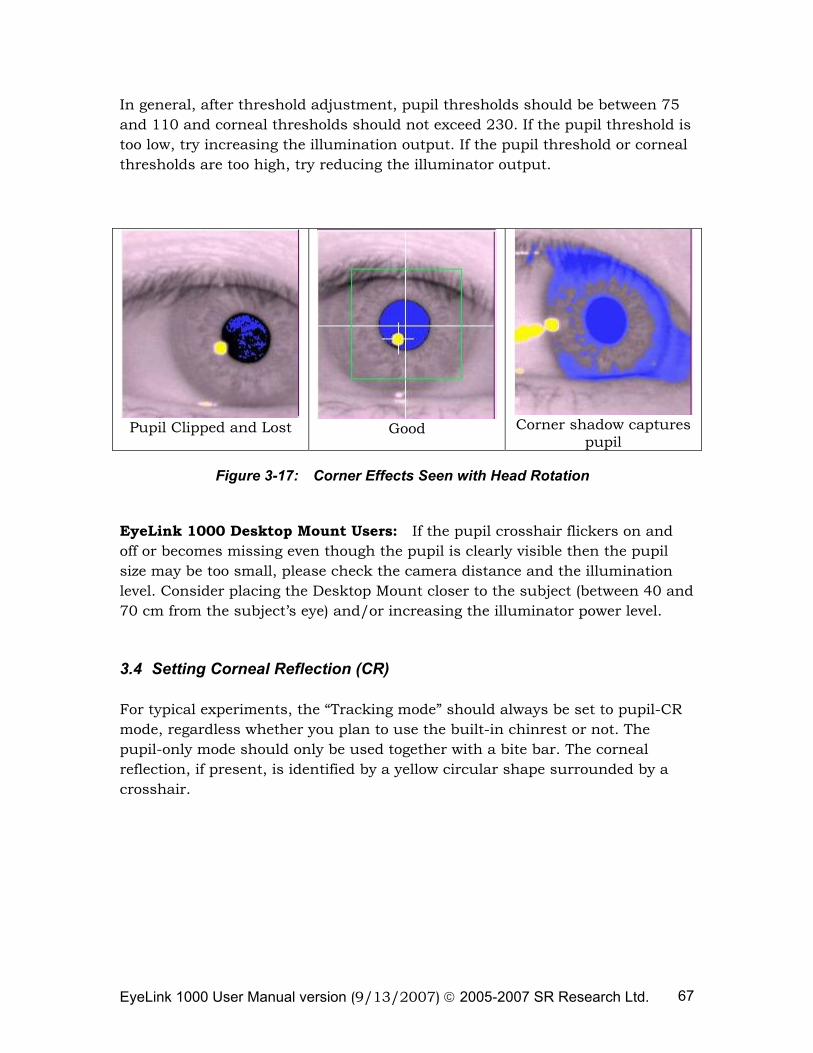
EyeLink 1000 User Manual version (9/13/2007) © 2005-2007 SR Research Ltd. 67
In general, after threshold adjustment, pupil thresholds should be between 75 and 110 and corneal thresholds should not exceed 230. If the pupil threshold is too low, try increasing the illumination output. If the pupil threshold or corneal thresholds are too high, try reducing the illuminator output.
Pupil Clipped and Lost
Good
Corner shadow captures
pupil
Figure 3-17: Corner Effects Seen with Head Rotation
EyeLink 1000 Desktop Mount Users: If the pupil crosshair flickers on and off or becomes missing even though the pupil is clearly visible then the pupil size may be too small, please check the camera distance and the illumination level. Consider placing the Desktop Mount closer to the subject (between 40 and 70 cm from the subject’s eye) and/or increasing the illuminator power level.
3.4 Setting Corneal Reflection (CR)
For typical experiments, the “Tracking mode” should always be set to pupil-CR mode, regardless whether you plan to use the built-in chinrest or not. The pupil-only mode should only be used together with a bite bar. The corneal reflection, if present, is identified by a yellow circular shape surrounded by a crosshair.
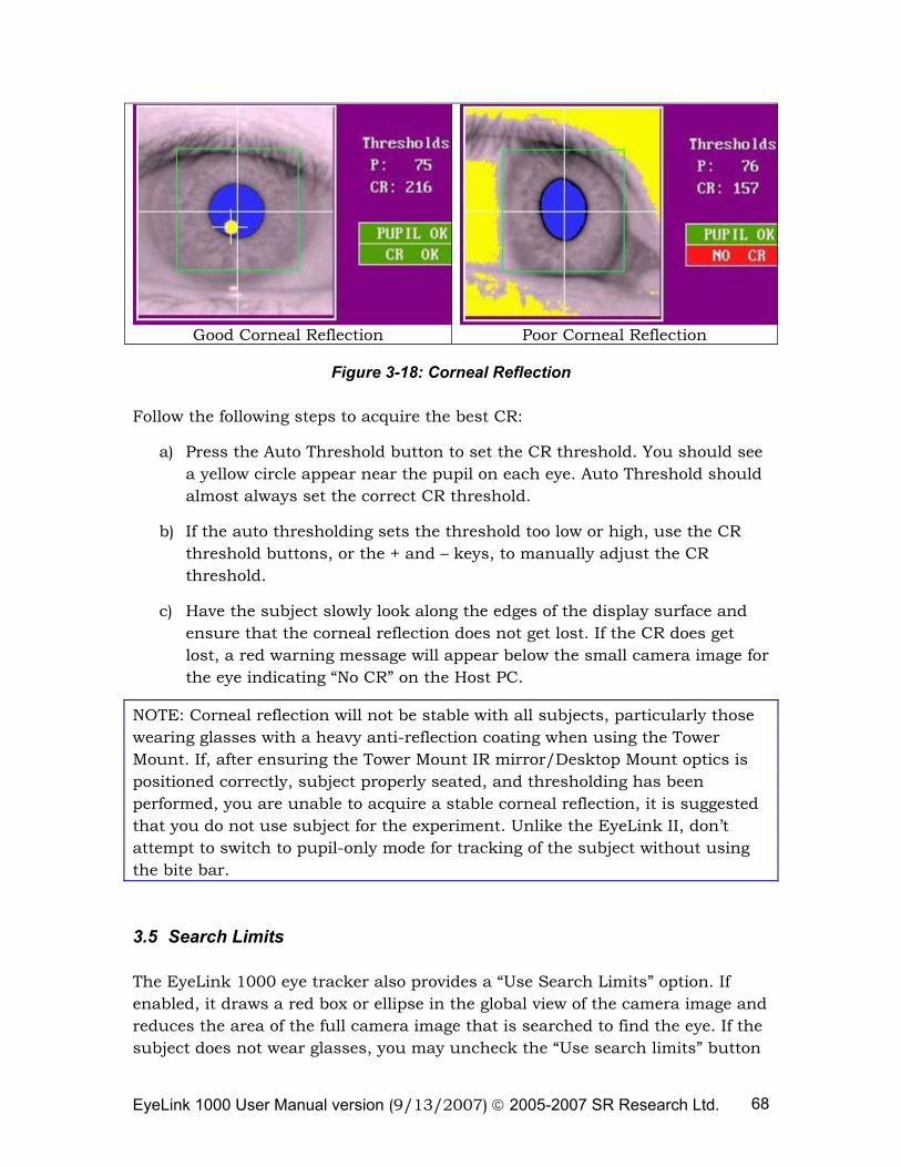
EyeLink 1000 User Manual version (9/13/2007) © 2005-2007 SR Research Ltd. 68
Good Corneal Reflection Poor Corneal Reflection
Figure 3-18: Corneal Reflection
Follow the following steps to acquire the best CR:
a) Press the Auto Threshold button to set the CR threshold. You should see a yellow circle appear near the pupil on each eye. Auto Threshold should almost always set the correct CR threshold.
b) If the auto thresholding sets the threshold too low or high, use the CR threshold buttons, or the + and – keys, to manually adjust the CR threshold.
c) Have the subject slowly look along the edges of the display surface and ensure that the corneal reflection does not get lost. If the CR does get lost, a red warning message will appear below the small camera image for the eye indicating “No CR” on the Host PC.
NOTE: Corneal reflection will not be stable with all subjects, particularly those wearing glasses with a heavy anti-reflection coating when using the Tower Mount. If, after ensuring the Tower Mount IR mirror/Desktop Mount optics is positioned correctly, subject properly seated, and thresholding has been performed, you are unable to acquire a stable corneal reflection, it is suggested that you do not use subject for the experiment. Unlike the EyeLink II, don’t attempt to switch to pupil-only mode for tracking of the subject without using the bite bar.
3.5 Search Limits
The EyeLink 1000 eye tracker also provides a “Use Search Limits” option. If enabled, it draws a red box or ellipse in the global view of the camera image and reduces the area of the full camera image that is searched to find the eye. If the subject does not wear glasses, you may uncheck the “Use search limits” button
EyeLink 1000 User Manual version (9/13/2007) © 2005-2007 SR Research Ltd. 69
on the Camera Setup screen. This allows the tracker to search for pupil position across the whole camera image in case the pupil position is lost. The “Use Search Limits” button should be checked for participants wearing glasses. This can be used to exclude other regions of the camera image (e.g., frame of the glasses) that may otherwise be detected as a pupil/CR reflection pattern. The disadvantage of using the search limits, however, is that if the participant completely removes their head from the head support and then puts it back in the head support device the search limits box may not be in the correct location to track the eye. This is especially the case when the “Move Limits” button on the Set Options screen is checked.
The size of the search limited for the selected eye can be adjusted by pressing ALT and cursor keys on the host keyboard together (ALT + ⇑ or ⇓ to adjust the height; ALT + ⇐ and ⇒ to adjust the width). The position of the search limits can be adjusted with SHIFT and cursor keys. In a binocular setup, size/position of the search limits can be adjusted for each of the eyes separately.
3.6 Pupil Tracking Algorithm
The EyeLink 1000 implements two pupil tracking algorithms: Centroid vs. Ellipse Fitting. The Centroid mode tracks the center of the thresholded pupil using a center of mass algorithm whereas the Ellipse mode determines the center of the pupil by fitting an ellipse to the thresholded pupil mass. In the ellipse mode, the host software draws a green ellipse around the pupil area, representing the ellipse fitting solution used to determine pupil position.
For most purposes, the centroid algorithm is recommended as it has very low noise. However, if the pupil may be significantly occluded (for example by the eyelids) the ellipse fitting algorithm may give a more accurate estimation of pupil position. The ellipse-fitting mode decreases drift potential and copes well with pupil occlusion but at the cost of a higher noise level.
The EyeLink Remote exclusively uses the ellipse-fitting pupil model.
NOTE: Pupil size or diameter data are based on the centroid model regardless of which model is used to determine gaze position.
3.7 Calibration
The preceding steps set up the EyeLink 1000 camera system to track the positions of the pupil and CR of the selected eye. Almost all eye-movement research requires information on the subject's point of gaze on a display of visual information, such as a screen of text. To compute this, we need to determine the correspondence between pupil position in the camera image and
EyeLink 1000 User Manual version (9/13/2007) © 2005-2007 SR Research Ltd. 70
gaze position on the subject display. We do this by performing a system calibration, displaying several targets for the subject to fixate. The pupil - CR position for each target is recorded, and the set of target and pupil - CR positions is used to compute gaze positions during recording.
There are several possible calibration types available, each of which serves different purpose. By default, a nine-point calibration type (“HV9”) is used. This is good for most of the eye tracking applications. However, if a large calibration region is used, the “HV13” calibration type should be used for best calibration accuracy. Press the “Set Options” button from the Camera Setup screen to display the Set Options screen. Check to ensure that the following options are selected for practice:
• Calibration type: 9-point grid (the EyeLink Remote has fewer calibration grid options than some other modes)
• Randomize target order: YES
• Auto-trigger pacing: 1000 msec
Press the “Previous Screen” button when done to return to Camera Setup.
Begin calibration by pressing the ‘Calibrate’ button from the Camera Setup menu. A calibration target will appear on both the Host PC display and the Display PC monitor. The subject display is drawn by the TRACK.EXE application, in response to commands from the EyeLink tracker. The Host PC screen will also display the raw pupil position as a moving colored circle, and a thresholded image. A status bar at the bottom-right of the display reports the progress of the calibration.
The pupil-position cursor will jump about when the subject looks about on the display, and becomes still when properly fixating the calibration target. Instructing the subject to carefully look at the white spot in the middle of the black calibration target will help improve fixation stability. Head movements during calibration should be discouraged: small head movements are corrected, but large movements will severely degrade calibration accuracy, due to distortion of the calibration data pattern and range.
If the cursor jumps continuously and rapidly, or disappears intermittently, the setup for the eye has problems. The eye-movement condition is also visible at the right side of the status bar at the bottom of the Host PC's display.
When the pupil appears stable to accept the first fixation, press the ‘Accept Fixation” button or the ↵ (ENTER) key or spacebar key. The pupil tends to come to rest gradually and to make small vergence movements at the start of the fixation, so do not respond too quickly. However, do not wait too long before accepting the fixation, as subjects soon begin to make involuntary saccades.
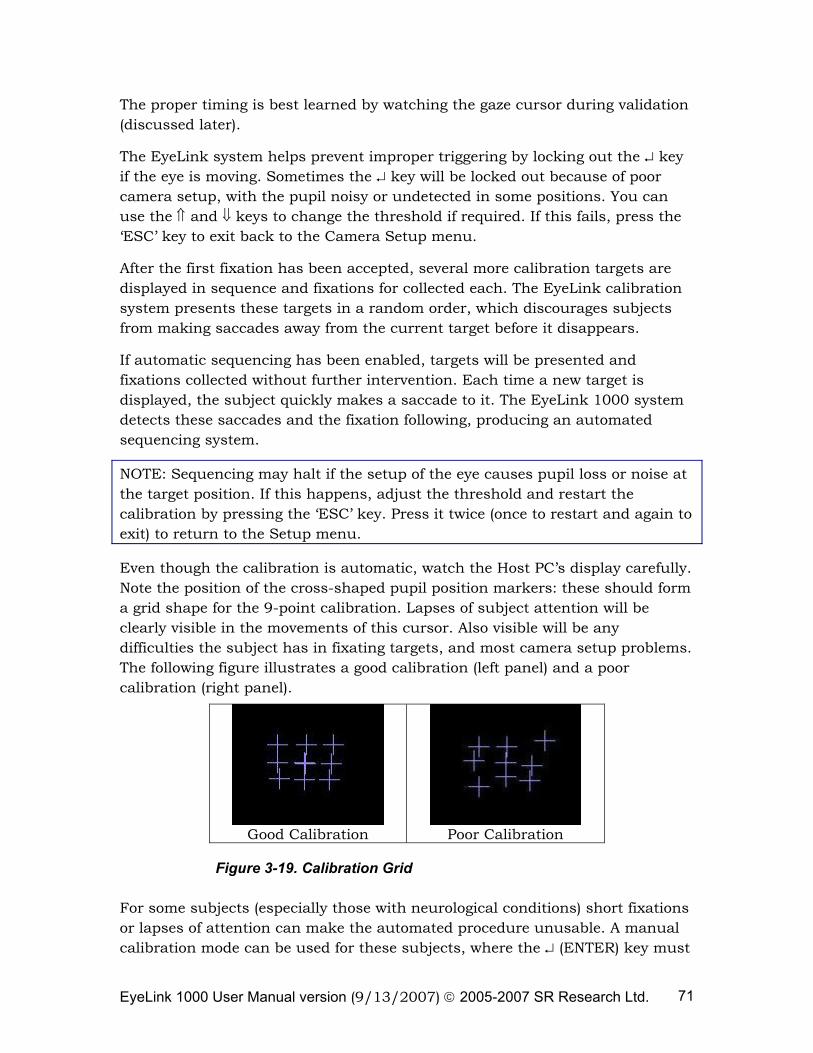
EyeLink 1000 User Manual version (9/13/2007) © 2005-2007 SR Research Ltd. 71
The proper timing is best learned by watching the gaze cursor during validation (discussed later).
The EyeLink system helps prevent improper triggering by locking out the ↵ key if the eye is moving. Sometimes the ↵ key will be locked out because of poor camera setup, with the pupil noisy or undetected in some positions. You can use the ⇑ and ⇓ keys to change the threshold if required. If this fails, press the ‘ESC’ key to exit back to the Camera Setup menu.
After the first fixation has been accepted, several more calibration targets are displayed in sequence and fixations for collected each. The EyeLink calibration system presents these targets in a random order, which discourages subjects from making saccades away from the current target before it disappears.
If automatic sequencing has been enabled, targets will be presented and fixations collected without further intervention. Each time a new target is displayed, the subject quickly makes a saccade to it. The EyeLink 1000 system detects these saccades and the fixation following, producing an automated sequencing system.
NOTE: Sequencing may halt if the setup of the eye causes pupil loss or noise at the target position. If this happens, adjust the threshold and restart the calibration by pressing the ‘ESC’ key. Press it twice (once to restart and again to exit) to return to the Setup menu.
Even though the calibration is automatic, watch the Host PC’s display carefully. Note the position of the cross-shaped pupil position markers: these should form a grid shape for the 9-point calibration. Lapses of subject attention will be clearly visible in the movements of this cursor. Also visible will be any difficulties the subject has in fixating targets, and most camera setup problems. The following figure illustrates a good calibration (left panel) and a poor calibration (right panel).
Good Calibration
Poor Calibration
Figure 3-19. Calibration Grid
For some subjects (especially those with neurological conditions) short fixations or lapses of attention can make the automated procedure unusable. A manual calibration mode can be used for these subjects, where the ↵ (ENTER) key must
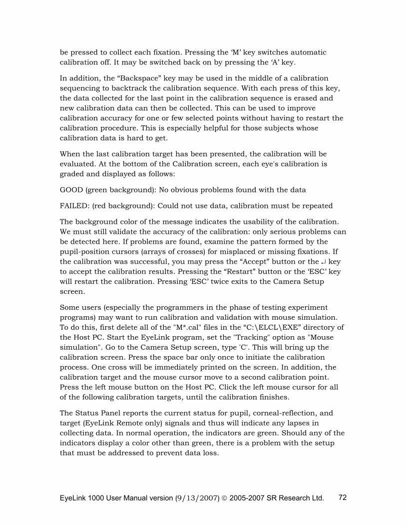
EyeLink 1000 User Manual version (9/13/2007) © 2005-2007 SR Research Ltd. 72
be pressed to collect each fixation. Pressing the ‘M’ key switches automatic calibration off. It may be switched back on by pressing the ‘A’ key.
In addition, the “Backspace” key may be used in the middle of a calibration sequencing to backtrack the calibration sequence. With each press of this key, the data collected for the last point in the calibration sequence is erased and new calibration data can then be collected. This can be used to improve calibration accuracy for one or few selected points without having to restart the calibration procedure. This is especially helpful for those subjects whose calibration data is hard to get.
When the last calibration target has been presented, the calibration will be evaluated. At the bottom of the Calibration screen, each eye's calibration is graded and displayed as follows:
GOOD (green background): No obvious problems found with the data
FAILED: (red background): Could not use data, calibration must be repeated
The background color of the message indicates the usability of the calibration. We must still validate the accuracy of the calibration: only serious problems can be detected here. If problems are found, examine the pattern formed by the pupil-position cursors (arrays of crosses) for misplaced or missing fixations. If the calibration was successful, you may press the “Accept” button or the ↵ key to accept the calibration results. Pressing the “Restart” button or the ‘ESC’ key will restart the calibration. Pressing ‘ESC’ twice exits to the Camera Setup screen.
Some users (especially the programmers in the phase of testing experiment programs) may want to run calibration and validation with mouse simulation. To do this, first delete all of the "M*.cal" files in the “C:\ELCL\EXE” directory of the Host PC. Start the EyeLink program, set the "Tracking" option as "Mouse simulation". Go to the Camera Setup screen, type 'C'. This will bring up the calibration screen. Press the space bar only once to initiate the calibration process. One cross will be immediately printed on the screen. In addition, the calibration target and the mouse cursor move to a second calibration point. Press the left mouse button on the Host PC. Click the left mouse cursor for all of the following calibration targets, until the calibration finishes.
The Status Panel reports the current status for pupil, corneal-reflection, and target (EyeLink Remote only) signals and thus will indicate any lapses in collecting data. In normal operation, the indicators are green. Should any of the indicators display a color other than green, there is a problem with the setup that must be addressed to prevent data loss.
EyeLink 1000 User Manual version (9/13/2007) © 2005-2007 SR Research Ltd. 73
Indicates Status of CR-Pupil OK = Pupil is visible SIZE = Pupil is too large MISSING = Pupil is missing
The pupil status error message “SIZE”, highlighted in yellow, indicates that the size of the pupil is too large or too small. This should not occur when the camera is mounted on the EyeLink 1000 head support tower as the camera to eye distance has been carefully calculated to ensure compatibility with a wide range of different pupil sizes. For the EyeLink Remote, the pupil “SIZE” warning typically suggests that the pupil size is too small because of the ambient lighting or the eye tracker is placed too far away from the subject.
The pupil status error message “MISSING” highlighted in red, indicates that the pupil is missing from the camera view. This could be that the participant is blinking. It could also be that there is a problem with camera setup. Please adjust as needed.
Indicates Status of Corneal OK = Corneal is visible MISSING = Corneal is missing
The corneal status error message “MISSING”, highlighted in red, indicates that the corneal reflection is not visible to the camera. See section 3.4 for details on how to set up corneal reflection properly. All status flags remain on for a minimum of 200 msec, even if the condition that caused the warning or error to be raised lasted for less than 200 msec.
3.8 Validation
It is important that problems with the calibration be identified and corrected before eye-movement recordings are ruined. By running a validation immediately after each calibration, the accuracy of the system in predicting gaze position from pupil position is scored. If performance is poor, the calibration should be immediately repeated.
In a validation, targets are presented on the subject display in a random order, similar to the calibration procedure. When the subject fixates these, the calibration is used to estimate the gaze position of the subject, and the error (difference between target position and computed gaze position) is estimated. Note: a scaling factor is built in for automatically generated validation points to pull in the corner positions (see the ‘validation_corner_scaling’ command setting in the CALIBR.INI file). This is used to limit validation to the useful part of the display.
EyeLink 1000 User Manual version (9/13/2007) © 2005-2007 SR Research Ltd. 74
The gaze-position error comes largely from errors in fixation data gathered during the calibration, which come from two sources: the eye-tracking system and physiological eye-movement control. The EyeLink system has extremely low pupil-position noise and very high resolution. These common sources of error in the eye-tracking system are virtually eliminated. One physiological source of calibration inaccuracy is the natural variability in fixation position on targets. Vergence eye movements also contribute.
For calibrations with 9 targets, it is highly likely that one or more targets will be fixated with an error of 1° or greater. Poor eye/camera setup can cause a highly distorted calibration pattern. Some subjects may show substantial drifts in gaze position during fixations or may not fixate carefully, adding to the errors.
To begin the validation procedure, select the “Validate” button or press the ‘V’ key in the Camera Setup screen. The Host PC display will show the gaze position as a round colored cursor. Note the movements of the cursors, and the change in relative horizontal position (vergence) following saccades. Once the cursor appears stable, and close to the target, press the ↵ (ENTER) key to accept the first fixation. The remaining points are collected automatically or manually, as in the calibration process.
As each fixation is collected, a cross is used to mark its computed position relative to the target. The error (in degrees) is printed next to the cross. Similar to the calibration procedure, the user can use the “Backspace” key in the middle of a validation sequence to redo data collection for the last or last few validation points collected. After the final fixation is collected, the average and worst errors are displayed at the bottom of the screen, and the accuracy is scored. Each eye is graded separately, using colored messages similar to the calibration results:
GOOD (green background): Errors are acceptable.
FAIR (grey background): Errors are moderate, calibration should be improved.
POOR: (red background): Errors are too high for useful eye tracking.
Observe the pattern of the errors for each of the targets. If only one target has a high error, the subject may simply have mis-fixated that point, and the validation may be repeated to check this: press ‘ESC’ to return to the Camera Setup screen, and ‘V’ to repeat the validation. If a regular pattern is seen (i.e. all fixations on the left side are too low) there was probably a calibration or camera setup problem. In this case, press ‘ESC’ to return to the Camera Setup screen, and re-calibrate.
EyeLink 1000 User Manual version (9/13/2007) © 2005-2007 SR Research Ltd. 75
3.9 Improving Calibration Quality
The quality of calibrations determines how useful the data recorded will be and how accurate the gaze calculation will be. Try some of these simple procedures to improve data quality and gaze accuracy:
• The threshold pupil area must be inside the pupil box (displayed as a red box around pupil) when the subject is looking at any area of the display. If a portion of the pupil exits this box, the pupil will be lost.
• The corneal reflection should never be lost or misidentified when the subject looks around the calibrated area.
• Always ask the subject to look at the four corners of the display after performing the camera setup. Watch for the warning signals on the tracker screen to make sure that the pupil and CR signal is not lost when the subject is doing so.
• Subjects who have never been calibrated before require some practice in stably fixating the calibration targets. Try to perform at least two calibrations per subject before beginning to collect data.
• Encourage subjects to sit still! A subject that doesn't sit still probably is not paying proper attention to the experimental task.
• When writing your own applications, try to match the background color of the screen during calibration and validation to that of the test displays. Changes in pupil size caused by large brightness differences can degrade the system accuracy.
• Always check for the pattern of the calibration grid. For a 9-point calibration, the fixation crosses should form three parallel horizontal (or close-to-horizontal) lines and three parallel vertical (or close-to-vertical) lines. Redo calibration or camera setup if you are not seeing this.
3.10 Recording Gaze Position
After the system is set up and calibrated, we can monitor gaze position in real time, and record it for later analysis or viewing. Pressing the “Output” button or the ‘O’ key from the Camera Setup screen will display the Output menu, where EyeLink Data Files (*.EDF) can be opened and closed, and analog output (if installed) can be controlled. TRACK.EXE automatically opens a data file ‘DATA.EDF’, but you can change this by opening a new file in this menu. Pressing ↵ (ENTER) or ‘O’ again will enter Output mode, and start display of gaze position and data recording.
EyeLink 1000 User Manual version (9/13/2007) © 2005-2007 SR Research Ltd. 76
In this session, we assume the TRACK application is running on the Display PC. When TRACK senses that the Host PC has entered Output mode, it sets up a recording session under its own control.
On the Display PC, it displays a page of text or a target grid on its own screen for the subject to read, alternating between recording sessions. The Host PC screen will show the pattern of boxes that corresponds to each letter or word on the subject’s display. This serves as a reference for the gaze-position cursor displayed by the EyeLink 1000 during recording, allowing the operator to see where the subject is looking and detect problems with eye-tracking errors or of subject’s inattention. Applications can create similar feedback displays by sending the display screen image to the tracker PC before recording begins.
TRACK displays the gaze position as a red cursor on the subject display. The cursor can be toggled on and off by the ‘G’ key on the Display PC keyboard. To implement this feedback, TRACK requests that EyeLink send it 250, 500, 1000, or 2000 samples per second of gaze-position via the EyeLink Windows DLL. This data is used to move the gaze cursor.
TRACK also sends commands to the Host PC to create a data file (DATA.EDF) on the Host PC’s hard disk, which contains samples, fixations, and saccade data. When the TRACK exits, this file will be automatically transferred from the Host PC to the Display PC. DATA.EDF may be viewed with EyeLink Data Viewer or processed with other EDF utilities. Information on the EDF file format can also be found in the Chapter 4 of the current document.
3.11 Drift Correction / Drift Checking
The drift correct screen displays a single target to the participant and then measures the difference between the computed fixation position during calibration and the current target. Unlike earlier EyeLink I and II eye trackers, we have found that correcting the calibration map based on the drift correction result has no significant effect in gaze accuracy. Therefore, the default drift correction behavior of the EyeLink 1000 system when in pupil-CR mode is to only report the calculated fixation error from the drift correction procedure and to not actually adjust the calibration map in any way. Therefore the drift correction procedure is better viewed as a “Drift Checking” procedure in the EyeLink 1000.
However, the user may opt to perform a drift correction at the beginning of each trial by computing and applying a corrective offset to the raw eye-position data. This can be done by changing the “driftcorrect_cr_disable” command setting in EL1000.INI file. It is important that before performing a drift
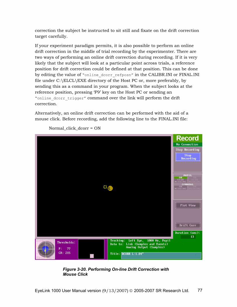
EyeLink 1000 User Manual version (9/13/2007) © 2005-2007 SR Research Ltd. 77
correction the subject be instructed to sit still and fixate on the drift correction target carefully.
If your experiment paradigm permits, it is also possible to perform an online drift correction in the middle of trial recording by the experimenter. There are two ways of performing an online drift correction during recording. If it is very likely that the subject will look at a particular point across trials, a reference position for drift correction could be defined at that position. This can be done by editing the value of “online_dcorr_refposn” in the CALIBR.INI or FINAL.INI file under C:\ELCL\EXE directory of the Host PC or, more preferably, by sending this as a command in your program. When the subject looks at the reference position, pressing ‘F9’ key on the Host PC or sending an “online_dcorr_trigger” command over the link will perform the drift correction.
Alternatively, an online drift correction can be performed with the aid of a mouse click. Before recording, add the following line to the FINAL.INI file:
Normal_click_dcorr = ON
Figure 3-20. Performing On-line Drift Correction with Mouse Click
EyeLink 1000 User Manual version (9/13/2007) © 2005-2007 SR Research Ltd. 78
This will bring up an additional clickable drift correction button in the record screen. Click on the “Drift Corr” button, which will flash periodically if enabled. Move the mouse cursor over the intended drift correction target and instruct the participant to fixate the target precisely. Press the button only once when the participant fixates stably. The drift correction may fail if there is no stable fixation data or if there is a large error between the current fixation and the target item. By default, the maximum acceptable error value (set by the ‘online_dcorr_maxangle’ command) is 5.0°.
3.12 Exiting EyeLink 1000
You can now close the EyeLink 1000 tracker program. Press the key combination ‘CTRL+ALT+Q’ from any point in the Host PC tracker program to exit to the command prompt.
3.13 EyeLink 1000 Setup Summary
It is suggested that you try the procedures in this section until you feel comfortable with the EyeLink 1000 setup, and can get reliable calibrations.
This is a summary of the steps detailed in the practice session. It assumes no setup problems are encountered.
• Start the EyeLink 1000 Host PC program
• Start TRACK.EXE on the Display PC.
• Have the subject seated in the chair comfortably. Adjust the height of the chair so that the subject’s eye line is at the upper part of the monitor.
• When using the Tower Mount, set the intended mirror angle and adjust the eye selection knob to track the intended eye. When using Desktop Mount, set the intended eye tracking mode (binocular vs. monocular) and adjust the position/angle of the Desktop Mount. When using EyeLink Remote, put the target sticker on the subject’s forehead and adjust the position/angle of the Desktop Mount.
• Press ↵ (ENTER) to start Setup mode. Press ENTER again to transfer the camera image to the Display PC.
• Click on the pupil position on the global view of the camera image to acquire the pupil position.
• Focus the camera image if it looks blurred.
EyeLink 1000 User Manual version (9/13/2007) © 2005-2007 SR Research Ltd. 79
• Set the threshold with the ‘A’ key, and fine-tune with ⇑ and ⇓ keys. Have the subject turn their head to check eye corners.
• Press ‘C’ to start calibration, press ↵ (ENTER) to collect first fixation, let sequence run by itself. Press ↵ (ENTER) to accept result, ‘ESC’ to repeat.
• Press ‘V’ to start validation, press ↵ (ENTER) to collect first fixation, let sequence run by itself. Press ↵ (ENTER) when finished.
• Repeat calibration if validation is poor
• Press ‘O’ ‘O’ to record eye movement data. ‘G’ on Display PC keyboard toggles the gaze cursor on and off.
• Press ‘CTRL+ALT+Q’ to exit the EyeLink 1000 Host PC application.
• Turn off the Host PC and the power to the camera at the end of the day.
3.14 Experiment Practice
The TRACK.EXE program is the most flexible way to practice the EyeLink 1000 setup, allowing almost any sequence of actions to be performed. In real experiments, the sequence of actions is much more defined. Usually the experiment begins with subject setup and calibration from the Setup menu, perhaps followed by practice trials. Then a series of experimental trials are performed, sometimes with a drift correction before each trial.
This flow allows little room for practice, and makes it important that initial setup and calibration be performed correctly and carefully validated. The EyeLink tracker has a built-in trial-abort menu, which may be used in experiments to terminate trials where setup problems are seen. The Setup menu may then be used to fix eye setup or calibration, and the interrupted trial may be restarted or skipped. This sequence requires co-operation from the experiment application, and example code is provided in the developer’s kit.
3.15 Next Steps: Other Sample Experiments
There are several sample experiments that are valuable demonstrations of how the EyeLink 1000 system can be used and programmed. This section describes each sample experiments purpose and use. For detailed information on the programming / API aspect of these samples, please refer to the EyeLink Programmer’s guide.
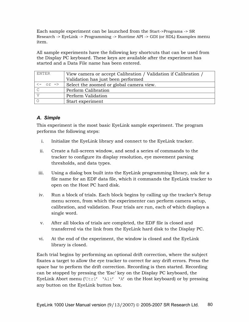
EyeLink 1000 User Manual version (9/13/2007) © 2005-2007 SR Research Ltd. 80
Each sample experiment can be launched from the Start->Programs -> SR Research -> EyeLink -> Programming -> Runtime API -> GDI (or SDL) Examples menu item. All sample experiments have the following key shortcuts that can be used from the Display PC keyboard. These keys are available after the experiment has started and a Data File name has been entered. ENTER View camera or accept Calibration / Validation if Calibration /
Validation has just been performed <- or -> Select the zoomed or global camera view. C Perform Calibration V Perform Validation O Start experiment A. Simple This experiment is the most basic EyeLink sample experiment. The program performs the following steps:
i. Initialize the EyeLink library and connect to the EyeLink tracker.
ii. Create a full-screen window, and send a series of commands to the tracker to configure its display resolution, eye movement parsing thresholds, and data types.
iii. Using a dialog box built into the EyeLink programming library, ask for a file name for an EDF data file, which it commands the EyeLink tracker to open on the Host PC hard disk.
iv. Run a block of trials. Each block begins by calling up the tracker’s Setup menu screen, from which the experimenter can perform camera setup, calibration, and validation. Four trials are run, each of which displays a single word.
v. After all blocks of trials are completed, the EDF file is closed and transferred via the link from the EyeLink hard disk to the Display PC.
vi. At the end of the experiment, the window is closed and the EyeLink library is closed.
Each trial begins by performing an optional drift correction, where the subject fixates a target to allow the eye tracker to correct for any drift errors. Press the space bar to perform the drift correction. Recording is then started. Recording can be stopped by pressing the ‘Esc’ key on the Display PC keyboard, the EyeLink Abort menu (‘Ctrl’ ‘Alt’ ‘A’ on the Host keyboard) or by pressing any button on the EyeLink button box.
EyeLink 1000 User Manual version (9/13/2007) © 2005-2007 SR Research Ltd. 81
B. Text This experiment is an extension of the Simple experiment and uses a slightly more complex process for drawing to the Display PC monitor. For more complex display such as screens of text or pictures, drawing takes too long to complete in one or two display refreshes. This makes the drawing process visible, and there is no clear stimulus onset for reaction time measurement. The code in the “text” template draws to a bitmap (an image in computer memory, not to the display), then copies it to the Display PC monitor, reducing the time to make the display visible. This also has the advantage of making the trial code more general: almost any stimulus can be displayed given its bitmap.
C. Picture The template “Picture” is almost identical to “Text”, except that images are loaded from BMP or JPEG files and displayed instead of text.
D. EyeData This template introduces the use of the link in transferring gaze-position data. This data can be used for gaze contingent or gaze control type paradigms. Gaze position data can be transferred in real time, or played back after recording has ended, which helps to separate recording from analysis.
The “Eyedata” template uses link data to display a real-time gaze cursor. The data is then played back after the trial, drawing the saccade paths and fixation points to the screen. The bitmap for the trial is a grid of letters.
E. GCWindow The most useful real-time experiment is a gaze-contingent display, where the part of the display the subject is looking at is changed, or where the entire display is modified depending on the location of gaze. These require high sampling rates and low delay, which the EyeLink 1000 tracker can deliver through the link.
This template demonstrates how to use the link’s real-time gaze-position data to display a gaze-contingent window. This is an area centered on the point of gaze that shows a foreground image, while areas outside the window show the background image. You supply full-screen sized bitmaps for these, which are stored in the bmp folder. You can use different images by replacing the one provided with the experiment with an image of your own with the same name.
F. Control
EyeLink 1000 User Manual version (9/13/2007) © 2005-2007 SR Research Ltd. 82
This template implements a computer interface that is controlled by the subject’s gaze. The participant can select one of a grid of letters by fixating on it. The template contains code to support many rectangular selection regions, but can be simplified if gaze in a single region is all that needs to be detected. The image for the trial is a grid of letters.
G. Dynamic This template consists of four experiment blocks. In the first block a red horizontal moving dot is presented which moves from left to right then back again repeatedly. The second block presents a red “/” which moves right to left then changes to “\” when moving left to right repeatedly. The third block presents white dots at three locations along the horizontal axis. The final fourth block presents a white dot, a few seconds later another white dot is shown. The original white dot then fades away.
EyeLink 1000 User Manual version (9/13/2007) © 2005-2007 SR Research Ltd. 83
4. Data Files
The EDF file format is used by the EyeLink tracker and supporting applications to record eye-movements and other data. It is designed to be space-efficient and flexible, allowing for complete records of experimental sessions and data. It adapts to monocular and binocular recording, with backwards-compatibility for future enhancements. The EyeLink 1000 EDF file format is backwards compatible with the original EyeLink and EyeLink II EDF file format. The EDF file format is a platform-portable binary record of eye-position and synchronization events. This format is used directly for EyeLink Data Viewer application, and may be translated by the EDF2ASC utility into a text-format ASC file. This file lists most of the important data in the EDF file in a more easily accessible format, but at the expense of much larger file size.
Note: By changing the File Sample Filter from Extra to Standard or Off, this will affect EyeLink Data Viewer, EDF2ASC, and other analysis tool data calculations. SR Research Ltd. recommends leaving the “File Sample Filter” setting on the Set Options screen to “Extra”.
4.1 File Contents
The EDF files contain two streams of data: eye-position samples (up to 2000 per second produced from the EyeLink tracker, depending on the system model) and events (eye-movement events such as saccades and fixations, subject responses, and synchronizing events from the experimental application). Both streams are time-synchronized for easy analysis. The file is organized into blocks of data, one for each recording session. Each block may have samples, events, or both. Also, the data items recorded in each sample or event may be configured at recording, and are available at the block start to aid in analysis. Samples are time-stamped in milliseconds and contain monocular or binocular eye-position data in eye-rotation angle (HREF) or display-gaze coordinated (GAZE). Pupil sizes as area or diameter are also recordable. Samples may also contain eye-movement resolution (used to compute true velocity or saccadic amplitudes), button presses, or the status of digital inputs. Eye-movement events record eye position changes identified by the EyeLink tracker's on-line parser, such as fixations, blinks, and saccades. Both the onset and end of these events are marked, allowing samples to be assigned to eye-movement periods without complex algorithms. Important data for analysis such as average position for fixations and peak velocity for saccades is also recorded in the events. Other events record subject responses (such as button presses) and synchronization and data messages from applications. These can be used to record the time of a change in the display, or an experimental condition.
EyeLink 1000 User Manual version (9/13/2007) © 2005-2007 SR Research Ltd. 84
4.2 Recording EDF Files
EDF files are created by the EyeLink 1000 tracker, recording eye-position data, events from the on-line parser, and button and input events. These are recorded only when the tracker is in output (recording) mode. Messages sent from applications on the Display PC through the Ethernet link may be recorded at any time. Recording EDF files involves opening a data file, recording data from one or more sessions in output mode, and closing the file. These operations can be performed manually using the EyeLink 1000 tracker application on the Host PC, or remotely from the Display PC through the Ethernet.
4.2.1 Recording from the EyeLink 1000 Host PC In some eye-tracking situations, it is most convenient to initiate the recording of eye movement data directly. For example, displays may be generated by manually-operated equipment, or by non-EyeLink applications. Special provisions must be made for display of the calibration pattern. By using the EyeLink 1000 tracker’s Output Screen, files may be opened and closed, and recording sessions may be started and stopped. Refer to Chapter 2 of this manual “EyeLink 1000 Tracker Application Operation” for information.
4.2.2 Recording from the EyeLink API or SR Research Experiment Builder Most eye-movement research involves running many subjects through a sequence of experimental trials, with tens or hundreds of recording blocks per file. This is best done by remote control over the link from an experimental application. The connection from the Display PC to the EyeLink 1000 tracker is implemented by an Ethernet link. Refer to the EyeLink Programmer’s Guide or SR Research Experiment Builder User Manual for details on how to use the Display PC software to set up and record EDF files.
4.3 The EyeLink On-Line Parser
The EyeLink 1000 system incorporates a unique on-line parsing system which analyzes eye position data into meaningful events and states (saccades, fixations, and blinks). For many experiments, such as reading or cognitive research, only the events need to be stored in the EDF file, reducing its size by 80% to 95%.
4.3.1 Parser Operation The parser uses velocity and acceleration-based saccade detection methods. Because of the EyeLink 1000 tracker’s exceptionally low noise levels and high spatial resolution, very little data filtering is needed and thus delay is kept small. The 250, 500, 1000, or 2000 Hz sampling rate gives a high temporal resolution of 4, 2, 1, or 0.5 millisecond (Note: Availability of some sampling rates and options depends on the system model).
EyeLink 1000 User Manual version (9/13/2007) © 2005-2007 SR Research Ltd. 85
For each data sample, the parser computes instantaneous velocity and acceleration and compares these to the velocity and acceleration thresholds. If either is above threshold, a saccade signal is generated. The parser will check that the saccade signal is on or off for a critical time before deciding that a saccade has begun or ended. This check does not affect the recorded time of the saccade start or end, but adds some delay to the real-time events sent through the link. During each saccade or fixation, data is collected on velocity, position, and pupil size. At the end of the saccade or fixation, this data is used to compute starting, ending, and average position, pupil size and velocity, as well as peak velocity. Velocity data is also converted into units of degrees per second using real-time resolution information. This data is then used to create events which are sent over the link and/or recorded in an EDF file. See the section 4.5.3 “Eye Movement Events” for more information on events.
4.3.2 Parser Limitations The EyeLink 1000 parser was designed for on-line, low delay identification of saccades and blinks. Detection of very small saccades may require off-line processing, as the special filtering and computation of global velocity cannot be performed on-line. In smooth pursuit research, the parser is less sensitive to small back-up saccades (opposite to the direction of pursuit) than forward saccades, due to the low peak velocity of back-up saccades. The parser only looks “ahead” in the data a short time to compute velocity and acceleration. This limits the data checking the parser can do. Post-processing or data cleanup may be needed to prepare data during analysis. For example, short fixations may need to be discarded or merges with adjacent fixations, or artifacts around blinks may have to be eliminated. Nonetheless, the EyeLink 1000 parser does an excellent job in most recording situations. Adjusting the configuration of the parser may help bias its performance for specific applications such as smooth pursuit or reading research. Its performance is easily checked: record eye movements using the display of interest, with both sample and event data. Then view the EDF file with EyeLink Data Viewer or convert the EDF file to an ASC file to see the correspondence between eye movements and the parser output.
4.3.3 EyeLink Parser Configuration The saccadic detection parameters for the EyeLink 1000 on-line parser may need to be optimized for the type of experimental investigation being performed. For example, neuropsychophysical researchers may need to detect small saccades amid pursuit or nystagmus, while reading researchers will need to detect only large saccades and will want fixation durations maximized. This
EyeLink 1000 User Manual version (9/13/2007) © 2005-2007 SR Research Ltd. 86
section explains the function of, and suggests values for, the most useful parser parameters. Some experimentation may be required to select the best parameters. The user can try different parser settings and perform recordings with full sample data recorded. The eye-movement data can then be viewed with EyeLink Data Viewer with saccades and blinks overlaid, to confirm the parsing accuracy. Once correct parameters are determined, they can be set by the EyeLink 1000 commands over the link as part of the experimental setup, or the EyeLink 1000 configuration file PARSER.INI (REMPARSE.INI for the EyeLink Remote) or FINAL.INI can be edited to change the default parameters.
4.3.4 Parser Data Type Three eye-position data types are available from the EyeLink 1000 tracker for each sample: raw pupil position, head-referenced angle, and gaze position (see the section 4.4 “File Data Types” for more information). The parser can use any one of these for detecting saccades and generating data for events. The parser data type is set by the EyeLink command “recording_parse_type”. It can be changed by editing the configuration file DEFAULTS.INI, or by sending a command over the link. The text of the command is one of:
recording_parse_type = GAZE recording_parse_type = HREF recording_parse_type = PUPIL
4.3.5 Saccadic Thresholds Three thresholds are used for saccade detection: motion, velocity, and acceleration. The values of these are in degrees, degrees/sec, and degrees/sec² respectively. The velocity threshold is the eye-movement velocity that must be exceeded for a saccade to be detected. A velocity threshold of 22 degrees per second allows detection of saccades as small as 0.3°, ideal for smooth pursuit and psychophysical research. A conservative threshold of 30°/sec is better for reading and cognitive research, shortening saccades and lengthening fixation durations. The larger threshold also reduces the number of microsaccades detected, decreasing the number of short fixations (less than 100 msec in duration) in the data. Some short fixations (2% to 3% of total fixations) can be expected, and most researchers simply discard these. Use of eye-movement acceleration is important for detection of small saccades, especially in smooth pursuit. Acceleration data has much more noise than velocity data, and thresholds of 4000°/sec2 for small saccade detection and 8000°/sec2 for reading and cognitive research are recommended. Lower acceleration thresholds will produce false saccade reports. Acceleration data and thresholds for the EyeLink 1000 system may be larger than those reported
EyeLink 1000 User Manual version (9/13/2007) © 2005-2007 SR Research Ltd. 87
for analog eye trackers. These systems use multi-pole filters for noise reduction that adds delay and smoothes the data, significantly reducing the measured acceleration. The saccadic motion threshold is used to delay the onset of a saccade until the eye has moved significantly. A threshold of 0.1° to 0.2° is sufficient for shortening saccades. Larger values may be used with caution to eliminate short saccades: for example, a threshold of 0.4° will always merge fixations separated by 0.5° or less, but may eliminate some 1° saccades as well. The threshold should be set to zero for non-cognitive research, or where statistics such as saccadic duration, amplitude and average velocity are required. Examples of the commands to set these thresholds are:
saccade_velocity_threshold = 30
saccade_acceleration_threshold = 8000
saccade_motion_threshold = 0.15
4.3.6 Pursuit Thresholds During smooth pursuit and nystagmus, saccades must be detected against a background of smooth eye motion as fast as 70°/sec. While acceleration can be used to detect these saccades, velocity data must also be used for reliable detection of all saccades. The EyeLink 1000 parser raises the saccadic velocity threshold during pursuit by the average velocity over the last 40 milliseconds. This is reliable, and does not degrade parser performance during non-pursuit eye movements. During long saccades such as the return sweep in reading, this fix up causes the saccadic velocity threshold to be raised. This is not a problem as long as the adjustment is limited, as it helps to prevent prolongation of these saccades by overshoots and glissades. The pursuit threshold limits the amount that the saccadic threshold can be raised. A limit of 60°/sec works well for most pursuit and other research, but may have to be raised if very rapid pursuit or nystagmus is being recorded. The limit is set in degrees per second. An example of this command is:
saccade_pursuit_fixup = 60
4.3.7 Fixation Updates Monitoring eye position or pupil size during fixations usually requires processing all samples produced by the tracker. This is acceptable for file data, but is expensive for real-time systems using data sent via the link. Fixation updates solve this problem by sending updates on eye position, pupil size, velocity etc. at regular intervals during a fixation. The first update is sent one
EyeLink 1000 User Manual version (9/13/2007) © 2005-2007 SR Research Ltd. 88
update interval after the start of the fixation, and the last is sent at the end of the fixation. Data is aggregated over a preset period, which lowers data noise. The interval between updates and the data accumulation period can both be set. Fixation updates are most useful for real-time display paradigms. In some studies, the subject is required to fixate a target while stimuli are presented. Fixation updates can be used to check gaze position every 100 msec or so. Computer interfaces operated via eye movements is a paradigm dramatically simplified by fixation updates. Actions are triggered by gaze on an active area of the screen for a critical duration. This is implemented simply by counting sequential fixation updates that fall within the area. Two commands set the fixation update interval and data accumulation period in milliseconds. Usually these are set to the same value. An interval of zero disables fixation update. An update interval of 50 or 100 msec is a good choice:
fixation_update_interval = 100
fixation_update_accumulate = 100
4.3.8 Other Parameters The EyeLink 1000 PARSER.INI configuration file contains other commands that configure the parser. These are of several types:
• Verification delays. These set the time in milliseconds that the parser requires a detector output (saccadic velocity or acceleration thresholds, or missing pupil for blink) to be stable before the parser changes its state and sends events to the data file or link. These values have been determined empirically, and there is little advantage to changing them.
• Parser filter types. Two velocity filters are available: fast and slow. The fast filter works better in most cases. The slow filter is less noise sensitive, but increases saccade duration and decreases sensitivity slightly.
• Saccade extension. This is intended to allow the saccade period to include the lower-velocity start and end of the saccadic period. This is usually disabled, as its effect is minor.
• Internal constants. These MUST NOT be changed.
4.3.9 Sample Configurations The complete set of commands for the most useful tracker configurations is given below. The cognitive configuration is conservative, is less sensitive to noise and ignores most saccades smaller than 0.6°. The psychophysical configuration is useful for neurological and smooth-pursuit research, and reports very small saccades. It also better estimates saccade durations and average velocities. Cognitive Configuration:
EyeLink 1000 User Manual version (9/13/2007) © 2005-2007 SR Research Ltd. 89
recording_parse_type = GAZE
saccade_velocity_threshold = 30
saccade_acceleration_threshold = 8000
saccade_motion_threshold = 0.15
saccade_pursuit_fixup = 60
fixation_update_interval = 0
Psychophysical configuration:
recording_parse_type = GAZE
saccade_velocity_threshold = 22
saccade_acceleration_threshold = 4000
saccade_motion_threshold = 0.0
saccade_pursuit_fixup = 60
fixation_update_interval = 0
4.3.10 Reparsing EyeLink Data Files The Host PC parses data in real time in order to make eye events immediately available to the Display PC. These events are recorded in the EDF file for later access by the DataViewer. The parameters used during the initial parsing are supplied in the REMPARSE.INI for the EyeLink Remote and in PARSER.INI for all other modes of recording.
Occasionally, researchers wish to evaluate the data using different parametric definitions. The EyeLink 1000 Host PC software (Version 4.0 or later) supports reparsing existing EyeLink 1000 EDF files. To do this, save the desired saccade detection configurations into a new .INI file. Copy the original EDF file to the current EyeLink host directory (“C:\ELCL\EXE” by default). From the DOS command prompt, type:
elcl -reparse {SOURCE_EDF} {DEST_EDF} -c {configuration_INI_FILE}
where {SOURCE_EDF} is the name of the original EDF file;
{DEST_EDF} is the name of the destination EDF file where the parsed data should be saved;
{configuration_INI_FILE} the intended configuration file should be used.
The following example illustrates how to reparse the TEST.EDF file with a new set of parser configurations contained in the PARSER2.INI file and save the output data to TEST_NEW.EDF.
EyeLink 1000 User Manual version (9/13/2007) © 2005-2007 SR Research Ltd. 90
ELCL -REPARSE TEST TEST_NEW -C PARSER2.INI
4.4 File Data Types
The data contents of an EDF file are organized in two streams: samples and events. Samples are used to record instantaneous eye position data, while events are used to record important occurrences, either from the experimental application or from changes in the eye data. Both samples and events can report eye data in several forms. These are discussed in the description of sample data. Eye movement data is parsed by the EyeLink 1000 tracker on-line and used to generate eye-movement events, which are discussed with application messages and button events.
4.4.1 Samples Samples are records of eye-position, pupil size, and button or input states. The EyeLink 1000 tracker can record up to 2000 samples per second in a monocular tracking mode or up to 1000 samples per second in a binocular tracking mode depending on your system configuration and tracker licensing. Each sample is stored as a binary record in the EDF file, with simple compression used to minimize disk space. Even with compression, recording 1000 samples per second will create very large EDF files: about 15K of data per second. Each sample may contain several data field, including:
• Time of the sample (timestamp) in milliseconds
• eye position data in gaze, HREF, or RAW data, monocular or binocular
• Pupil size, monocular or binocular
• Button or input port state bits
All samples contain a timestamp, recorded in milliseconds. The time is measured from the time when the tracker software was started. This timestamp makes detection of missing samples possible, as well as simplifying processing of data. Usually all samples produced by the EyeLink 1000 tracker are recorded. Other types of sample data are discussed in greater detail below.
4.4.2 Position Data Eye position data is produced by the EyeLink 1000 tracker every 0.5, 1, 2 or 4 milliseconds depending on the tracking mode and speed set. It is then processed to compute eye rotation angles and to compensate for subject head motions. The processed data in one or all of these forms may be recorded in the
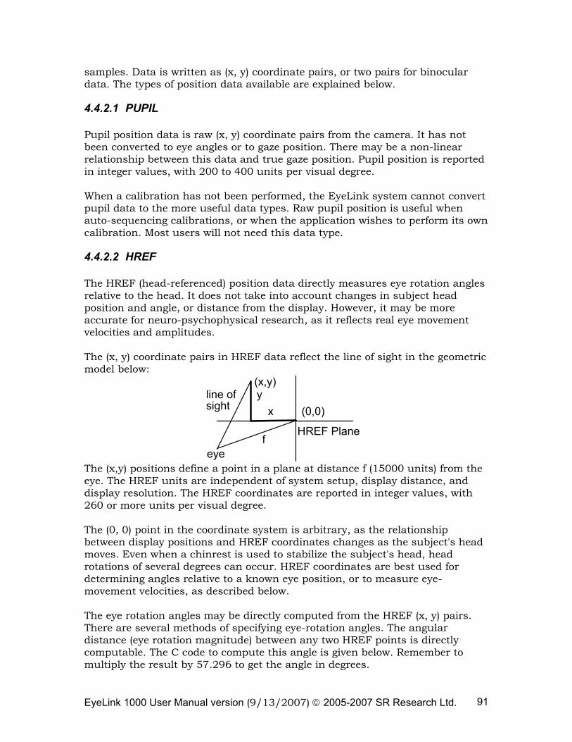
EyeLink 1000 User Manual version (9/13/2007) © 2005-2007 SR Research Ltd. 91
samples. Data is written as (x, y) coordinate pairs, or two pairs for binocular data. The types of position data available are explained below.
4.4.2.1 PUPIL Pupil position data is raw (x, y) coordinate pairs from the camera. It has not been converted to eye angles or to gaze position. There may be a non-linear relationship between this data and true gaze position. Pupil position is reported in integer values, with 200 to 400 units per visual degree. When a calibration has not been performed, the EyeLink system cannot convert pupil data to the more useful data types. Raw pupil position is useful when auto-sequencing calibrations, or when the application wishes to perform its own calibration. Most users will not need this data type.
4.4.2.2 HREF The HREF (head-referenced) position data directly measures eye rotation angles relative to the head. It does not take into account changes in subject head position and angle, or distance from the display. However, it may be more accurate for neuro-psychophysical research, as it reflects real eye movement velocities and amplitudes. The (x, y) coordinate pairs in HREF data reflect the line of sight in the geometric model below:
eye
(0,0)xyline of
sight
f
(x,y)
HREF Plane
The (x,y) positions define a point in a plane at distance f (15000 units) from the eye. The HREF units are independent of system setup, display distance, and display resolution. The HREF coordinates are reported in integer values, with 260 or more units per visual degree. The (0, 0) point in the coordinate system is arbitrary, as the relationship between display positions and HREF coordinates changes as the subject's head moves. Even when a chinrest is used to stabilize the subject's head, head rotations of several degrees can occur. HREF coordinates are best used for determining angles relative to a known eye position, or to measure eye-movement velocities, as described below. The eye rotation angles may be directly computed from the HREF (x, y) pairs. There are several methods of specifying eye-rotation angles. The angular distance (eye rotation magnitude) between any two HREF points is directly computable. The C code to compute this angle is given below. Remember to multiply the result by 57.296 to get the angle in degrees.
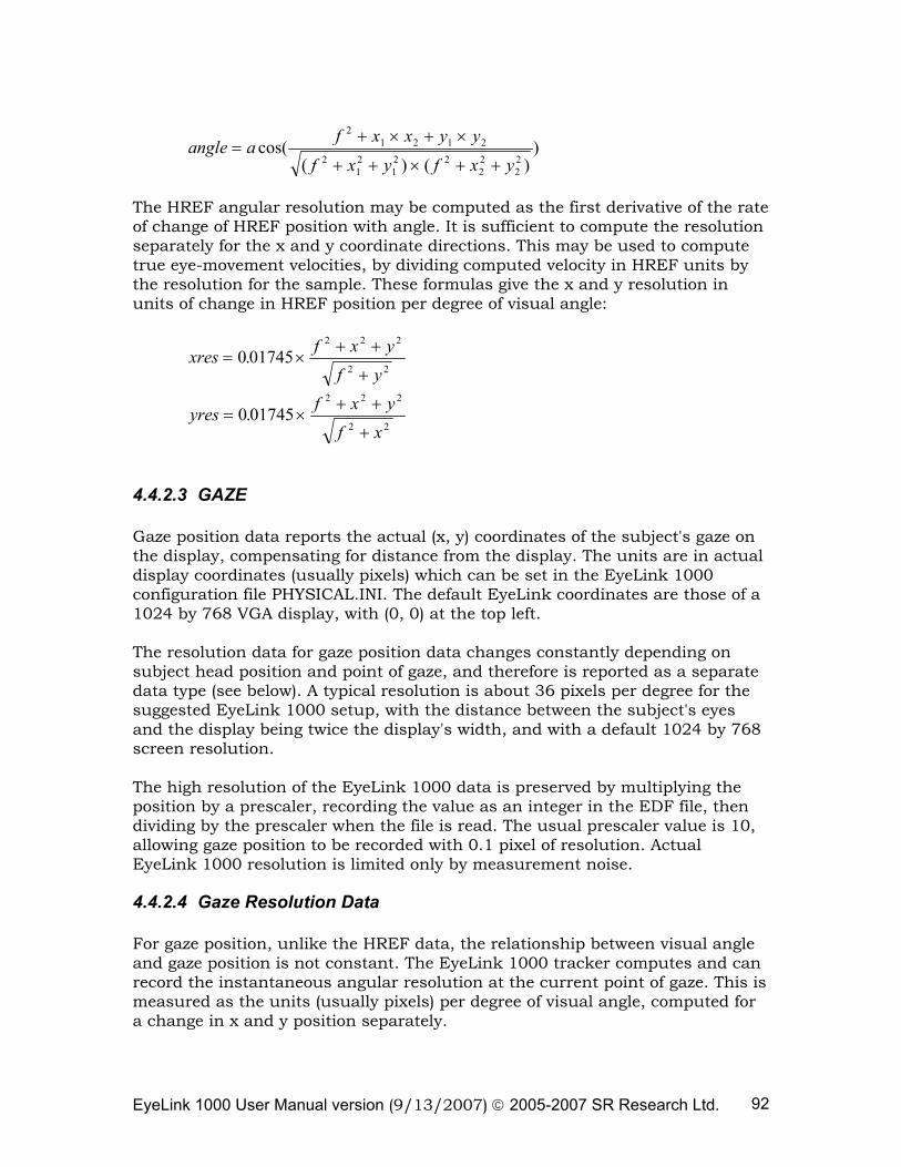
EyeLink 1000 User Manual version (9/13/2007) © 2005-2007 SR Research Ltd. 92
angle a f x x y y
f x y f x y=
+ × + ×
+ + × + +cos(
( ) ( ))
21 2 1 2
212
12 2
22
22
The HREF angular resolution may be computed as the first derivative of the rate of change of HREF position with angle. It is sufficient to compute the resolution separately for the x and y coordinate directions. This may be used to compute true eye-movement velocities, by dividing computed velocity in HREF units by the resolution for the sample. These formulas give the x and y resolution in units of change in HREF position per degree of visual angle:
xres f x yf y
= ×+ +
+0 01745
2 2 2
2 2.
yres f x yf x
= ×+ +
+0 01745
2 2 2
2 2.
4.4.2.3 GAZE Gaze position data reports the actual (x, y) coordinates of the subject's gaze on the display, compensating for distance from the display. The units are in actual display coordinates (usually pixels) which can be set in the EyeLink 1000 configuration file PHYSICAL.INI. The default EyeLink coordinates are those of a 1024 by 768 VGA display, with (0, 0) at the top left. The resolution data for gaze position data changes constantly depending on subject head position and point of gaze, and therefore is reported as a separate data type (see below). A typical resolution is about 36 pixels per degree for the suggested EyeLink 1000 setup, with the distance between the subject's eyes and the display being twice the display's width, and with a default 1024 by 768 screen resolution. The high resolution of the EyeLink 1000 data is preserved by multiplying the position by a prescaler, recording the value as an integer in the EDF file, then dividing by the prescaler when the file is read. The usual prescaler value is 10, allowing gaze position to be recorded with 0.1 pixel of resolution. Actual EyeLink 1000 resolution is limited only by measurement noise.
4.4.2.4 Gaze Resolution Data For gaze position, unlike the HREF data, the relationship between visual angle and gaze position is not constant. The EyeLink 1000 tracker computes and can record the instantaneous angular resolution at the current point of gaze. This is measured as the units (usually pixels) per degree of visual angle, computed for a change in x and y position separately.
EyeLink 1000 User Manual version (9/13/2007) © 2005-2007 SR Research Ltd. 93
This resolution data may be used to estimate distances between gaze positions, and to compute velocities of eye movements. To compute the angular distance of two points, compute the x and y angular distances of the points separately by dividing the distance in pixels by the average of the resolutions at the two points, then compute the Euclidean distance from the x and y distances. For instantaneous velocity in degrees per second, compute the x and y velocities, then divide each by the x or y resolution, square and add the x and y velocities, and take the square root. Resolution is computed at the point of gaze on the display, and can vary up to 15% over the display. The resolution data in an EDF file is recorded using a prescaler for extra precision, and noted in the gaze-position section.
4.4.3 Pupil Size Data Pupil size is also measured by the EyeLink 1000 system, at up to 2000 samples per second depending on your tracker version. It may be reported as pupil area, or pupil diameter. The pupil size data is not calibrated, and the units of pupil measurement will vary with subject setup. Pupil size is an integer number, in arbitrary units. Typical pupil area is 100 to 10000 units, with a precision of 1 unit, while pupil diameter is in the range of 400-16000 units. Both measurements are noise-limited, with noise levels of 0.2% of the diameter. This corresponds to a resolution of 0.01 mm for a 5 mm pupil. Pupil size measurements are affected by up to 10% by pupil position, due to the optical distortion of the cornea of the eye, and camera-related factors. If research using pupil size is to be performed, the subject should not move their eyes during the trials. They can be presented with a fixation point with aural stimulus presentation, or a single stimulus position at display center may be used. It is also possible to counterbalance stimulus position during the experiment.
4.4.4 Button Data The state of up to 8 buttons or input port bits may be recorded in each sample. Button ports, bits, and polarity may be set in the EyeLink 1000 tracker configuration file BUTTONS.INI. The button data consists of two 8-bit fields, recorded as a 16-bit number. The lower 8 bits contain the current status of the 8 buttons (bit = 0 if off, 1 if pressed). Each of the upper 8 bits will be set to 1 if its button has changed since the last sample. The least-significant bit in each byte corresponds to button 1, and the most-significant to button 8.
EyeLink 1000 User Manual version (9/13/2007) © 2005-2007 SR Research Ltd. 94
4.5 Events
One of the most significant aspects of the EyeLink 1000 tracking system and the EDF file format is its on-line processing of eye-movement data to identify and record events such as fixations and saccades. This eliminates the need for recording of sample data for many types of research, and achieves a data compression of 20:1 or greater. Samples need only be recorded for data validation or if sample-by-sample eye position or velocity is required. Events can record application data such as the time of a display change and experimental conditions, or real-time events such as button presses. Events also define the start and end of blocks of data in the EDF file, allowing applications to process data recorded with different data types. Each event contains one or two timestamps (in milliseconds) and several data fields. Data for each event is compressed, and an extendable data format allows compatibility with future expanded file formats. Note that not all the event data listed here is available through the EDF2ASC translator program.
4.5.1 Messages The most flexible event type is the message event. A message is most often text, but can contain any type of binary data as well, up to a maximum of 300 bytes. Messages are created by application software, and forwarded over the link to the EyeLink tracker, which timestamps the data and writes it to the EDF file. The application does not need precise time keeping, since link delays are usually very low (on the order of 1 or 2 milliseconds). Message events are used for two main purposes. They serve to precisely record the time of important events, such as display changes, subject responses, etc. They also record experiment-specific data, such as trial conditions. Message events consist of a millisecond timestamp, and the message data. A message is most often text, but can contain any type of binary data as well. For text data, a zero byte at the end of the text is recommended for compatibility with applications written in C. A message data length field provides Pascal string compatibility, and allows binary data to be recorded in the message. Current EyeLink applications only support text messages with zero-terminated strings. It is also recommended that messages be shorter than 120 characters.
4.5.2 Buttons Each button event records a change in state (pressed or released, 1 or 0) of up to 8 buttons or input port bits, monitored by the EyeLink 1000 tracker. Button ports, bits, and polarity may be set in the EyeLink 1000 tracker configuration file BUTTONS.INI.
EyeLink 1000 User Manual version (9/13/2007) © 2005-2007 SR Research Ltd. 95
Each button event contains a timestamp (in milliseconds) of the time the button was pressed, and a word of button data. This consists of two 8-bit fields, recorded as a 16-bit number. The lower 8 bits contain the current status of the 8 buttons (bit = 0 if off, 1 if pressed). Each of the upper 8 bits will be set to 1 if its button has changed since the last sample. The least-significant bit in each byte corresponds to button 1, and the most-significant is button 8. Button events are usually recorded at the start of each recording block, with all upper 8 bits (change flags) set to 0. This allows applications to track the current button state at all times.
4.5.3 Eye Movement Events Events are generated by the EyeLink 1000 tracker in real-time from the eye-movement data stream. These provide an efficient record of the data in a form ready to use for most types of eye-movement research. The use of events simplifies the analysis of sample data as well. For example, analysis of pursuit gain requires rejection of saccades, which are clearly marked in the events. Eye-movement events are generated in pairs: one event at the start of an eye-movement condition, and another at the end of the condition. When used in real-time processing with data set via the link, the event pairs allow an application to monitor eye movement state in real time. These pairs accurately label the samples in a file between the events, as the file is read from beginning to end. Eye-movement events are always labeled by which eye generated the event. If binocular data is recorded, a separate start and end event is generated for each eye. The time differences between eyes are very important for neurological analysis, for example. Start events contain the time of the start of the eye-movement condition. They may also contain the state of the eye at the onset of the condition: for example, the position and pupil size at the start of a fixation. End events contain both the start and end time of the condition. The end time is actually the time of the last sample in the condition, so length of a condition must be computed as the difference between the end and start times plus the time between samples (1, 2 or 4 milliseconds). End events also contain summary data on the condition as well: average gaze position of a fixation, for example. Eye-movement events are always labeled by which eye generated the event. The main classes of data events are summarized below.
4.5.3.1 Record Blocks Each block of recorded data in an EDF file begins with one or both of a STARTSAMPLES or STARTEVENTS event. These contain the time of the recording start, and specify what data can be expected to follow. This allows for
EyeLink 1000 User Manual version (9/13/2007) © 2005-2007 SR Research Ltd. 96
flexible adaptation to almost any file-data configuration. Information included in the start events include:
• Which eye recorded from • Sample data rate • Sample data contents • Event data contents • Event types included • Gaze-position and velocity prescalers
Each block of recorded data ends with one or both of an ENDSAMPLES or ENDEVENTS event. This simply terminates the data block, and specifies the time that recording ended. The text files generated from EDF files by the EDF2ASC translator utility create a simplified form of START and END events. A single START or END line is produced for both sample and event blocks, which specifies which eye was recorded from, and whether samples, events, or both, are present in the following data block. Other data is given on following SAMPLES, EVENTS, PRESCALER, etc. lines.
4.5.3.2 Fixations The on-line EyeLink 1000 tracker parser processes eye-position data, identifying saccades and fixations and compiling data on these conditions. For fixations, these data include:
• The time of the first and last sample in the fixation
• The eye that generated the event
• Average HREF or gaze position data
• Average pupil size
• Gaze-data angular resolution
All of this data may appear in the ENDFIX event that terminates the fixation. Only the starting data can appear in the STARTFIX event that initiates the fixation. In a sorted EDF file or a text ASC file (produced by EDF2ASC) that contains both samples and events, the STARTFIX event will precede the first sample in the file that is part of the fixation, and the ENDFIX event will follow the last sample in the fixation. This allows the sample data in the files to be processed by saccade or fixation in a single pass. The data contained in STARTFIX and ENDFIX events may be configured by modifying the DATA.INI file for the EyeLink 1000 tracker. For most research, only simple fixation statistics are required, such as average position and pupil size. STARTFIX events may also be configured to contain only the start time of the fixation.
EyeLink 1000 User Manual version (9/13/2007) © 2005-2007 SR Research Ltd. 97
Other data in the ENDFIX event may be useful for some types of analysis. The resolution may be used to estimate angular distance between fixations. Subtract the x and y position data for the fixations, divide by the average corresponding resolution data, and compute the Euclidean distance: dx = (x1 - x2) / ( (rx1 + rx2)/2.0); dy = (y1 - y2) / ( (ry1 + ry2)/2.0); dist = sqrt(dx*dx + dy*dy);
4.5.3.3 Fixation Updates Data within a fixation can be broken into smaller time segments, useful for real-time analysis and control via eye movements. FIXUPDATE events may be produced at regular intervals within a fixation, and contain data for a specified length of time within the fixation. The data recorded in the FIXUPDATE event is similar to that in the ENDFIX event. FIXUPDATE events are most useful in real-time applications using the link. Recording samples in the EDF file is more useful for most psychophysical research.
4.5.3.4 Saccades The EyeLink 1000 tracker's parser detects saccades by the velocity and acceleration of the eye movements. Because of variations in acceleration profiles, the onset and offset point of saccades can vary by one or two samples from "ideal" segmentation done by hand. Nonetheless, the saccadic data compiled by the parser is sufficient for most neuro-psychophysical research, including smooth pursuit. Most cognitive research will ignore the saccadic data, using the fixation data produced by the EyeLink 1000 parser. The saccadic data produced for saccades includes:
• The time of the first and last sample in the saccade • The eye that generated the event • Start and end HREF or gaze position data • Peak eye-movement velocity • Start and end gaze-data angle. • Gaze-data angular resolution
All of these data may appear in the ENDSACC event that terminates the fixation. Only the starting data can appear in the STARTSACC event that initiates the saccade. In a sorted EDF file or a text ASC file (produced by EDF2ASC) that contains both samples and events, the STARTSACC event will precede the first sample in the file that is part of the saccade, and the ENDSACC event will follow the last sample in the saccade. This allows the sample data in the files to be processed by saccade or fixation in a single pass. The data contained in STARTSACC and
EyeLink 1000 User Manual version (9/13/2007) © 2005-2007 SR Research Ltd. 98
ENDSACC events may be configured by modifying the DATA.INI file for the EyeLink tracker. Saccadic events may be eliminated entirely, if only fixation data is required. STARTSACC events may also be configured to contain only the start time of the saccade. The peak and average velocity data for saccades is especially valuable for neuro-psychophysical work. These are the absolute velocities measured as the Euclidean sum of x and y components. The EyeLink 1000 parser computes velocity by use of a 9-sample moving filter. This is optimal for detection of small saccades, minimizes extension of saccade durations, and preserves saccadic peak velocities. Other data in the ENDSACC event may be useful for some types of analysis. The start and end position, and start and end resolution, may be used to compute saccadic amplitude. This is more easily done by multiplying average velocity by the saccadic duration: dist = 1000.0 * (end_time - start_time + 1.0) * avg_velocity; In general, the saccadic amplitude will be slightly less than the distance between average position of the preceding and following fixations, as saccades do not include sub-threshold velocity parts of the eye movement that precede and follow the rapid phase.
4.5.3.5 Blinks The STARTBLINK and ENDBLINK events bracket parts of the eye-position data where the pupil size is very small, or the pupil in the camera image is missing or severely distorted by eyelid occlusion. Only the time of the start and end of the blink are recorded. Blinks are always preceded and followed by partial occlusion of the pupil, causing artificial changes in pupil position. These are sensed by the EyeLink 1000 parser, and marked as saccades. The sequence of events produced is always:
• STARTSACC
• STARTBLINK
• ENDBLINK
• ENDSACC Note that the position and velocity data recorded in the ENDSACC event is not valid. All data between the STARTSACC and ENDSACC events should be discarded. The duration of the blink may be computed by either the duration of the missing pupil between the STARTBLINK and ENDBLINK events, or the difference between the ENDSACC and STARTSACC events in the sequence.
EyeLink 1000 User Manual version (9/13/2007) © 2005-2007 SR Research Ltd. 99
Fixation immediately preceding and following blinks should be examined carefully, as they may have been truncated or produced by the blink process. Discarding fixations shorter than 100 ms proceeding or following blinks will eliminate most artifacts.
4.6 Setting File Contents
The data recorded in samples and events may be set in the EyeLink 1000 configuration file DATA.INI, or by sending commands to the tracker across the link, via the API eyecmd_printf(). Similar commands exist for samples and events sent over the link for real-time applications.
4.6.1 Sample Data The sample data written to the EDF file is controlled by the "file_sample_data" command, which is followed by a list of data types to include. A single keyword is included for each type: Keyword Data Type LEFT, RIGHT
Sets the intended tracking eye (usually include both LEFT and… RIGHT)
GAZE includes screen gaze position data GAZERES includes units-per-degree screen resolution at point of gaze HREF HTARGET
head-referenced eye position data target distance and X/Y position (EyeLink Remote only)
PUPIL raw pupil coordinates AREA pupil size data (diameter or area) BUTTON buttons 1-8 state and change flags STATUS warning and error flags (not yet supported) INPUT input port data lines (not yet supported) The default data is:
file_sample_data = LEFT,RIGHT,GAZE,GAZERES,AREA,STATUS
Usually, data for both eyes is enabled, and the menus in the EyeLink 1000 tracker are used to set which eye is actually tracked. Recording of gaze and pupil area is essential for most work, and resolution is important if velocity is to be computed later. Recording of HREF data is optional. For the EyeLink Remote, the HTARGET flag should always be included in the recording: file_sample_data = LEFT,RIGHT,GAZE,GAZERES,HTARGET,AREA,STATUS
4.6.2 Event Data
EyeLink 1000 User Manual version (9/13/2007) © 2005-2007 SR Research Ltd. 100
Eye-movement events are generated by processing one of the types of eye movement data (PUPIL, HREF, or GAZE) as specified by the "recording_parse_type" command (the default setting is GAZE). This command may be edited in the DEFAULTS.INI file of the EyeLink 1000 tracker, or may be sent over the link. recording_parse_type = <data type: one of PUPIL, HREF, or GAZE> The data type used for parsing will always be included in the event data. Other data reported for eye-movement events are controlled with the "file_event_data" command. This is followed by a list of data types and options, selected from the list below: Keyword Effect GAZE includes display (gaze) position data. GAZERES includes units-per-degree screen resolution (for start, end of event) HREF includes head-referenced eye position AREA includes pupil area or diameter VELOCITY includes velocity of parsed position-type (average, peak, start and
end) STATUS includes warning and error flags, aggregated across event (not yet
supported) FIXAVG include ONLY averages in fixation end events, to reduce file size NOSTART start events have no data other than timestamp The "file_event_data" command may be edited in the DATA.INI file of the EyeLink 1000 tracker, or may be sent over the link. Some example settings are given below: GAZE,GAZERES,AREA,HREF,VELOCITY - default: all useful data GAZE,GAZERES,AREA,FIXAVG,NOSTART - reduced data for fixations GAZE,AREA,FIXAVG,NOSTART - minimal data
4.6.3 Event Types The "file_event_filter" command specified what type of events will be written to the EDF file. It may be changed in the DATA.INI file of the EyeLink 1000 tracker, or may be sent over the link. The command is followed by a list of data types and options, selected from the list below: Keyword Effect LEFT, RIGHT Sets the intended tracking eye (usually include both LEFT and
RIGHT) FIXATION includes fixation start and end events FIXUPDATE includes fixation (pursuit) state update events SACCADE includes saccade start and end events BLINK includes blink start and end events
EyeLink 1000 User Manual version (9/13/2007) © 2005-2007 SR Research Ltd. 101
MESSAGE includes messages (ALWAYS use) BUTTON includes button 1..8 press or release events INPUT includes changes in input port lines (not yet supported) These examples of the command are the default event set, and a fixation-only configuration:
file_event_filter= LEFT,RIGHT,FIXATION,SACCADE,BLINK,MESSAGE,BUTTON
file_event_filter = LEFT,RIGHT,FIXATION,BLINK,MESSAGE,BUTTON
4.7 EDF File Utilities
A number of utility programs are included in the EyeLink 1000 package, to process and view EDF files. The utility EDF2ASC translates EDF files into text ASC files for processing with user applications. The EyeLink Data Viewer, an optional tool, allows displaying, filtering, and reporting output of EyeLink Data Files. Please check EyeLink Data Viewer User’s Manual for details.
4.8 Using ASC Files
The EDF file format is an efficient storage format for eye movement data, but is relatively complex to support. To make the data in EDF files accessible, the translator EDF2ASC converts the files into a text version that is easily accessible from almost any programming language. The converted ASC files contain lines of text, with each line containing data for a single sample, event or data parameter. The EDF2ASC utility reads one or more EDF files, creating text files with the same name but with the ASC extension. It scans the input file, reordering data as required, and converting samples and events into lines of text. It can also compute resolutions and instantaneous velocity for sample data. The ASC file is about twice as large as the original EDF files. EDF2ASC converter utility can be run from the GUI interface (from your computer desktop, click “Start -> Programs -> SR Research -> EyeLink -> Utilities -> Visual EDF2ASC” assuming that you have installed the EyeLink Data Viewer software). The user can also run the EDF2ASC converter from the DOS command line prompt, assuming that Windows Display Software has been installed. To translate an EDF file from the command line prompt, type "edf2asc" followed by the name of the file to be translated and any conversion options. Wildcards (* and ?) may be used in the input file name, allowing conversion of multiple EDF files to ASC files with the same name. Optionally, a second file name can be specified for the output ASC file. Many options exist for the file conversion. One set of options will be best for your work, and creation of a single-line batch file (called, for example, E2A.BAT) will make the use of the translator easier. The following table lists commonly-used options.
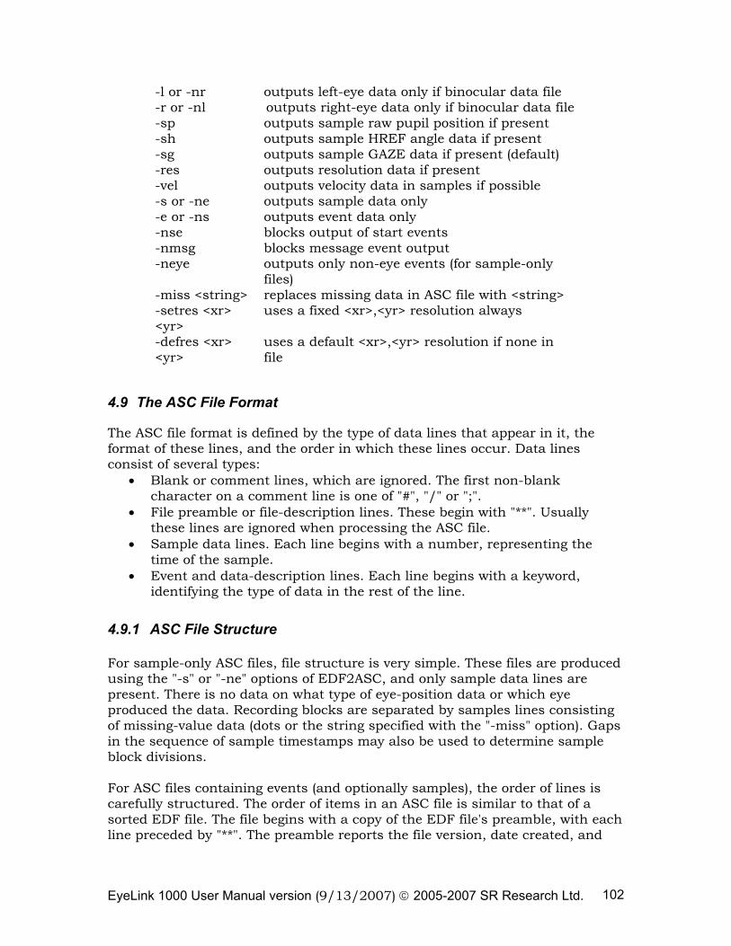
EyeLink 1000 User Manual version (9/13/2007) © 2005-2007 SR Research Ltd. 102
-l or -nr outputs left-eye data only if binocular data file -r or -nl outputs right-eye data only if binocular data file -sp outputs sample raw pupil position if present -sh outputs sample HREF angle data if present -sg outputs sample GAZE data if present (default) -res outputs resolution data if present -vel outputs velocity data in samples if possible -s or -ne outputs sample data only -e or -ns outputs event data only -nse blocks output of start events -nmsg blocks message event output -neye outputs only non-eye events (for sample-only
files) -miss <string> replaces missing data in ASC file with <string> -setres <xr> <yr>
uses a fixed <xr>,<yr> resolution always
-defres <xr> <yr>
uses a default <xr>,<yr> resolution if none in file
4.9 The ASC File Format
The ASC file format is defined by the type of data lines that appear in it, the format of these lines, and the order in which these lines occur. Data lines consist of several types:
• Blank or comment lines, which are ignored. The first non-blank character on a comment line is one of "#", "/" or ";".
• File preamble or file-description lines. These begin with "**". Usually these lines are ignored when processing the ASC file.
• Sample data lines. Each line begins with a number, representing the time of the sample.
• Event and data-description lines. Each line begins with a keyword, identifying the type of data in the rest of the line.
4.9.1 ASC File Structure For sample-only ASC files, file structure is very simple. These files are produced using the "-s" or "-ne" options of EDF2ASC, and only sample data lines are present. There is no data on what type of eye-position data or which eye produced the data. Recording blocks are separated by samples lines consisting of missing-value data (dots or the string specified with the "-miss" option). Gaps in the sequence of sample timestamps may also be used to determine sample block divisions. For ASC files containing events (and optionally samples), the order of lines is carefully structured. The order of items in an ASC file is similar to that of a sorted EDF file. The file begins with a copy of the EDF file's preamble, with each line preceded by "**". The preamble reports the file version, date created, and
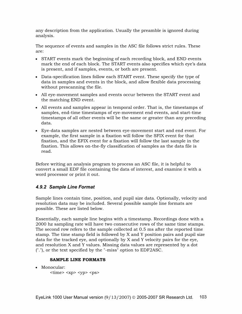
EyeLink 1000 User Manual version (9/13/2007) © 2005-2007 SR Research Ltd. 103
any description from the application. Usually the preamble is ignored during analysis. The sequence of events and samples in the ASC file follows strict rules. These are:
• START events mark the beginning of each recording block, and END events mark the end of each block. The START events also specifies which eye’s data is present, and if samples, events, or both are present.
• Data-specification lines follow each START event. These specify the type of data in samples and events in the block, and allow flexible data processing without prescanning the file.
• All eye-movement samples and events occur between the START event and the matching END event.
• All events and samples appear in temporal order. That is, the timestamps of samples, end-time timestamps of eye-movement end events, and start-time timestamps of all other events will be the same or greater than any preceding data.
• Eye-data samples are nested between eye-movement start and end event. For example, the first sample in a fixation will follow the SFIX event for that fixation, and the EFIX event for a fixation will follow the last sample in the fixation. This allows on-the-fly classification of samples as the data file is read.
Before writing an analysis program to process an ASC file, it is helpful to convert a small EDF file containing the data of interest, and examine it with a word processor or print it out.
4.9.2 Sample Line Format Sample lines contain time, position, and pupil size data. Optionally, velocity and resolution data may be included. Several possible sample line formats are possible. These are listed below. Essentially, each sample line begins with a timestamp. Recordings done with a 2000 hz sampling rate will have two consecutive rows of the same time stamps. The second row refers to the sample collected at 0.5 ms after the reported time stamp. The time stamp field is followed by X and Y position pairs and pupil size data for the tracked eye, and optionally by X and Y velocity pairs for the eye, and resolution X and Y values. Missing data values are represented by a dot ("."), or the text specified by the "-miss" option to EDF2ASC. SAMPLE LINE FORMATS
• Monocular: <time> <xp> <yp> <ps>
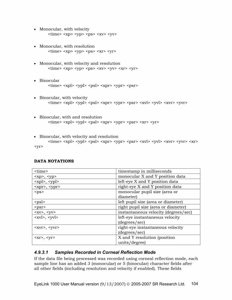
EyeLink 1000 User Manual version (9/13/2007) © 2005-2007 SR Research Ltd. 104
• Monocular, with velocity <time> <xp> <yp> <ps> <xv> <yv>
• Monocular, with resolution <time> <xp> <yp> <ps> <xr> <yr>
• Monocular, with velocity and resolution <time> <xp> <yp> <ps> <xv> <yv> <xr> <yr>
• Binocular <time> <xpl> <ypl> <psl> <xpr> <ypr> <psr>
• Binocular, with velocity <time> <xpl> <ypl> <psl> <xpr> <ypr> <psr> <xvl> <yvl> <xvr> <yvr>
• Binocular, with and resolution <time> <xpl> <ypl> <psl> <xpr> <ypr> <psr> <xr> <yr>
• Binocular, with velocity and resolution <time> <xpl> <ypl> <psl> <xpr> <ypr> <psr> <xvl> <yvl> <xvr> <yvr> <xr> <yr> DATA NOTATIONS <time> timestamp in milliseconds <xp>, <yp> monocular X and Y position data <xpl>, <ypl> left-eye X and Y position data <xpr>, <ypr> right-eye X and Y position data <ps> monocular pupil size (area or
diameter) <psl> left pupil size (area or diameter) <psr> right pupil size (area or diameter) <xv>, <yv> instantaneous velocity (degrees/sec) <xvl>, <yvl> left-eye instantaneous velocity
(degrees/sec) <xvr>, <yvr> right-eye instantaneous velocity
(degrees/sec) <xr>, <yr> X and Y resolution (position
units/degree)
4.9.3.1 Samples Recorded in Corneal Reflection Mode If the data file being processed was recorded using corneal reflection mode, each sample line has an added 3 (monocular) or 5 (binocular) character fields after all other fields (including resolution and velocity if enabled). These fields
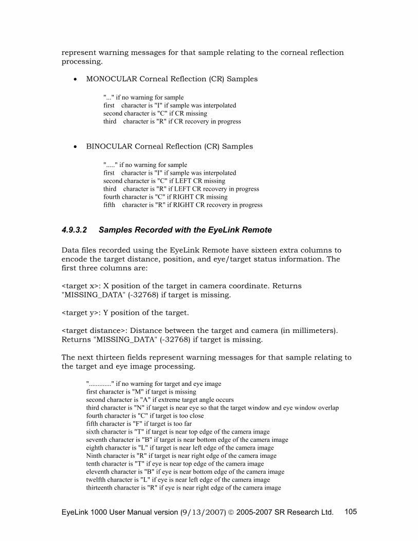
EyeLink 1000 User Manual version (9/13/2007) © 2005-2007 SR Research Ltd. 105
represent warning messages for that sample relating to the corneal reflection processing.
• MONOCULAR Corneal Reflection (CR) Samples
"..." if no warning for sample first character is "I" if sample was interpolated second character is "C" if CR missing third character is "R" if CR recovery in progress
• BINOCULAR Corneal Reflection (CR) Samples
"....." if no warning for sample first character is "I" if sample was interpolated second character is "C" if LEFT CR missing third character is "R" if LEFT CR recovery in progress fourth character is "C" if RIGHT CR missing fifth character is "R" if RIGHT CR recovery in progress
4.9.3.2 Samples Recorded with the EyeLink Remote Data files recorded using the EyeLink Remote have sixteen extra columns to encode the target distance, position, and eye/target status information. The first three columns are: <target x>: X position of the target in camera coordinate. Returns "MISSING_DATA" (-32768) if target is missing. <target y>: Y position of the target. <target distance>: Distance between the target and camera (in millimeters). Returns "MISSING_DATA" (-32768) if target is missing. The next thirteen fields represent warning messages for that sample relating to the target and eye image processing. "............." if no warning for target and eye image
first character is "M" if target is missing second character is "A" if extreme target angle occurs third character is "N" if target is near eye so that the target window and eye window overlap fourth character is "C" if target is too close fifth character is "F" if target is too far sixth character is "T" if target is near top edge of the camera image seventh character is "B" if target is near bottom edge of the camera image eighth character is "L" if target is near left edge of the camera image Ninth character is "R" if target is near right edge of the camera image tenth character is "T" if eye is near top edge of the camera image eleventh character is "B" if eye is near bottom edge of the camera image twelfth character is "L" if eye is near left edge of the camera image thirteenth character is "R" if eye is near right edge of the camera image
EyeLink 1000 User Manual version (9/13/2007) © 2005-2007 SR Research Ltd. 106
4.9.3 Event Line Formats Each type of event has its own line format. These use some of the data items listed below. Each line begins with a keyword (always in uppercase) and items are separated by one or more tabs or spaces. DATA NOTATIONS <eye> which eye caused event ("L" or "R") <time> timestamp in milliseconds <stime> timestamp of first sample in milliseconds
<etime> timestamp of last sample in milliseconds
<dur> duration in milliseconds <axp>, <ayp> average X and Y position
<sxp>, <syp> start X and Y position data
<exp>, <eyp> end X and Y position data
<aps> average pupil size (area or diameter) <av>, <pv> average, peak velocity (degrees/sec) <ampl> saccadic amplitude (degrees) <xr>, <yr> X and Y resolution (position units/degree)
4.9.3.3 Messages
• MSG <time> <message>
A message line contains the text of a time stamped message. This will have been sent to the EyeLink 1000 tracker by an application, and contains data for analysis or timestamps important events such as display changes or subject responses. The <message> text fills the entire line after the timestamp and any blank space following it.
4.9.3.4 Buttons
• BUTTON <time > <button #> <state>
Button lines report a change in state of tracker buttons 1 through 8. The <button #> reports which button has changed state. The <state> value will be 1 if the button has been pressed, 0 if it has been released. Tracker buttons may be created to monitor any digital input port bit, and may be created by link commands or in the tracker configuration file BUTTONS.INI.
4.9.3.5 Block Start & End
EyeLink 1000 User Manual version (9/13/2007) © 2005-2007 SR Research Ltd. 107
• START <time> <eye> <types>
• END <time> <types> RES <xres> <yres>
START lines mark the beginning of a block of recorded samples, events, or both. The start time is followed by a list of keywords which specify the eye recorded from, and the types of data lines in the block. The eye recorded from is specified by "LEFT" for left-eye, "RIGHT" for right-eye, and both "LEFT" and "RIGHT" for binocular. The types of data lines included are specified by "SAMPLES" for samples only, "EVENTS" for events only, and both "SAMPLES" and "EVENTS" for both. END lines mark the end of a block of data. The <types> are specified, as it is possible to turn recording of samples and events on and off independently. However, this is not suggested, and for most applications the <types> in the END line can be ignored. The two values following the "RES" keyword are the average resolution for the block: if samples are present, it is computed from samples, else it summarizes any resolution data in the events. Note that resolution data may be missing: this is represented by a dot (".") instead of a number for the resolution.
4.9.3.6 Fixations
• SFIX <eye> <stime>
• EFIX <eye> <stime> <etime> <dur> <axp> <ayp> <aps>
• EFIX <eye> <stime> <etime> <dur> <axp> <ayp> <aps> <xr> <yr>
The start of fixations are reported with a SFIX line, which can be eliminated with the EDF2ASC "-nse" option. The <eye> is "L" or "R", indicating the eye's data that produced the event.
The end of and summary data on the fixation is reported with the EFIX line. This reports the time of the first and last sample in the fixation, and computes the duration of the fixation in milliseconds. The average X and Y eye position (the type of position data is determined when the event was generated) and the average pupil size (area or diameter) are reported. Optionally, the eye-position angular resolution (in units per visual degree) is given as well.
All samples that are within the fixation will be listed between the SFIX and EFIX event for each eye, simplifying data analysis.
4.9.3.7 Saccades
• SSACC <eye> <stime>
• ESACC <eye> <stime> <etime> <dur> <sxp> <syp> <exp> <eyp> <ampl> <pv>
EyeLink 1000 User Manual version (9/13/2007) © 2005-2007 SR Research Ltd. 108
• ESACC <eye> <stime> <etime> <dur> <sxp> <syp> <exp> <eyp> <ampl> <pv> <xr> <yr>
The start of saccades are reported with a SSACC line, which can be eliminated with the EDF2ASC "-nse" option from the command line prompt or by enabling “Block Start Event Output” from the EDF2ASC converter GUI preference settings. The <eye> is "L" or "R", indicating the eye's data that produced the event. The end of and summary data on the saccade are reported with the ESACC line. This reports the time of the first and last sample in the saccade, and computes its duration in milliseconds. The X and Y eye position at the start and end of the saccade (<sxp>, <syp>, <exp>, <eyp>) are listed. The total visual angle covered in the saccade is reported by <ampl>, which can be divided by (<dur>/1000) to obtain the average velocity. Peak velocity is given by <pv>. Optionally, the eye-position angular resolution (in units per visual degree) is given as well. All samples that are within the saccade will be listed between the SSACC and ESACC events for each eye, simplifying data analysis.
4.9.3.8 Blinks
• SBLINK <eye> <stime>
• EBLINK <eye> <stime> <etime> <dur>
Blinks (periods of data where the pupil is missing) are reported by the SBLINK and EBLINK lines. The time of the start of the blink is indicated by the SBLINK line, which can be eliminated with the EDF2ASC "-nse" option. The <eye> is "L" or "R", indicating the eye's data that produced the event. The end and duration are given in the EBLINK event.
Blinks are always embedded in saccades, caused by artificial motion as the eyelids progressively occlude the pupil of the eye. Such artifacts are best eliminated by labeling and SSACC...ESACC pair with one or more SBLINK events between them as a blink, not a saccade. The data contained in the ESACC event will be inaccurate in this case, but the <stime>, <etime>, and <dur> data will be accurate.
It is also useful to eliminate any short (less than 120 millisecond duration) fixations that precede or follow a blink. These may be artificial or be corrupted by the blink.
4.9.4 Data-Specification Lines Immediately following a START line, several lines of data specifications may be present. These lines contain more extensive data than the START line about what data can be expected in the START...END block. These are most easily
EyeLink 1000 User Manual version (9/13/2007) © 2005-2007 SR Research Ltd. 109
processed by creating a set of flags for each possible data option (left-eye events, right-eye samples, sample velocity, etc.), clearing these when the START line is encountered, and setting the appropriate flags when keywords ("LEFT", "VEL", etc.) are encountered in a data specification line.
• PRESCALER <prescaler>
If gaze-position data or gaze-position resolution is used for saccades and events are used, they must be divided by this value. For EDF2ASC, the prescaler is always 1. Programs that write integer data may use a larger prescaler (usually 10) to add precision to the data.
• VPRESCALER <prescaler>
If velocity data is present, it must be divided by this value. For EDF2ASC, the prescaler is always 1. Programs that write integer data may use a larger prescaler (usually 10) to add precision to the data.
• EVENTS <data type> <eye> <data options>
This specifies what types of data is present in event lines, as a sequence of keywords. The <data type> is one of "GAZE", "HREF" or "PUPIL". The eye recorded will be one word ("LEFT" or "RIGHT"). The <data option> keywords currently supported are:
o "RES" for resolution data (both may be present). o “RATE” for the sample rate (250.00, 500.00, 1000.0, or 2000.0) o “TRACKING” for the tracking mode (P = Pupil, CR = Corneal
Reflection) o “FILTER” for the filter level used (0=off, 1=standard, 2=extra)
• SAMPLES <data type> <eye> <data options>
This specifies what types of data is present in sample lines, as a sequence of keywords. The <data type> is one of "GAZE", "HREF" or "PUPIL". The eye recorded will be "LEFT" or "RIGHT". The <data option> keywords currently supported are:
o "VEL" for instantaneous velocity data o "RES" for resolution data (both may be present). o “RATE” for the sample rate ((250.00, 500.00, 1000.0, or 2000.0) o “TRACKING” for the tracking mode (P = Pupil, CR = Corneal
Reflection) o “FILTER” for the filter level used (0=off, 1=standard, 2=extra)
4.10 Processing ASC Files
An ASC file is a simple text file, and thus can be accessed by almost any programming language. The usual way to process the file is to read each line
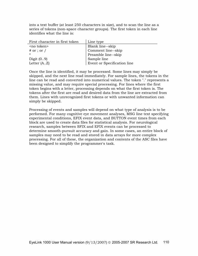
EyeLink 1000 User Manual version (9/13/2007) © 2005-2007 SR Research Ltd. 110
into a text buffer (at least 250 characters in size), and to scan the line as a series of tokens (non-space character groups). The first token in each line identifies what the line is: First character in first token Line type <no token> Blank line--skip # or ; or / Comment line--skip * Preamble line--skip Digit (0..9) Sample line Letter (A..Z) Event or Specification line Once the line is identified, it may be processed. Some lines may simply be skipped, and the next line read immediately. For sample lines, the tokens in the line can be read and converted into numerical values. The token "." represents a missing value, and may require special processing. For lines where the first token begins with a letter, processing depends on what the first token is. The tokens after the first are read and desired data from the line are extracted from them. Lines with unrecognized first tokens or with unwanted information can simply be skipped. Processing of events and samples will depend on what type of analysis is to be performed. For many cognitive eye movement analyses, MSG line text specifying experimental conditions, EFIX event data, and BUTTON event times from each block are used to create data files for statistical analysis. For neurological research, samples between SFIX and EFIX events can be processed to determine smooth-pursuit accuracy and gain. In some cases, an entire block of samples may need to be read and stored in data arrays for more complex processing. For all of these, the organization and contents of the ASC files have been designed to simplify the programmer's task.
EyeLink 1000 User Manual version (9/13/2007) © 2005-2007 SR Research Ltd. 111
5. System Care
5.1 Maintenance
The EyeLink 1000 system should require little maintenance under normal use. If the IR mirror is dusted, it can be cleaned with the cleaning cloth we supplied. If the mirror is dirty (e.g., smudged with finger prints), please apply some cleaning solution we supplied and then wipe clean with the cloth. The forehead rest and the chinrest pad may be wiped with a damp cloth if cleaning is required. Additional replacement pads can be purchased; please contact SR Research for details.
5.2 Storage and Transportation
Between uses, it is recommended that the EyeLink 1000 be left mounting on the table. If the EyeLink 1000 system is not going to be used for an extended period, you may wish to disconnect the cables from the computer and pack them in the shipping case. The EyeLink 1000 high-speed frame grabber, Ethernet card, as well as the optional Analog card, may be left inside the Host PC, although it may be removed if this computer is going to be used for another purpose, to prevent theft or loss. Important: The head support tower should only be held by the vertical posts and should NEVER be held by the mirror or the components attached to the mirror. We recommend you have somebody available to assist you mounting the head-support tower onto the table to prevent damages to the IR mirror or other parts of the tower. For long-term storage, shipping, or transportation, it is recommended that the EyeLink 1000 tower mount or Desktop Mount and cables be stored in the shipping box that you originally received the system in. Store the shipping case above freezing and below 40°C, and avoid high-humidity conditions which might cause water to condense within the tower and damage the optics. Be sure to follow the unpacking and installation instructions when returning the packaged unit to operation (see the EyeLink 1000 Installation Guide). If the EyeLink 1000 card is also to be packaged, remove it from the computer and place it into its anti-static bag, then into its slot in the foam.
EyeLink 1000 User Manual version (9/13/2007) © 2005-2007 SR Research Ltd. 112
6. Important Information
6.1 Safety
6.1.1 Eye Illumination Safety WARNING: Illuminators must only be connected to EyeLink CL camera, and only the supplied cables may be used. CAUTION: Use of a controls or adjustments or performance of procedures other than those specified herein may result in hazardous radiation exposure.
CLASS 1 LED DEVICE IEC 60825-1 (Ed. 1.2:2001)
The EyeLink CL illuminators are compliant with the IEC-60825-1 LED
safety standard as a Class 1 LED device. This standard has been or is in the
process of being adopted by most countries, and regulates many aspects of LED
and laser eye safety, including retinal, corneal and skin safety. Class 1 products
are “safe under reasonably foreseeable conditions of operation, including the
use of optical instruments for intrabeam viewing”.
As these illuminators may be used in situations where they may be viewed
for long periods of time, some precautions should be observed. Our experience
has been that even safe levels of IR illumination can eventually cause some
discomfort due to the slight drying effect of even this low level of illumination.
(This is especially true for wearers of contact lenses). SR Research recommends
that the illuminators not be used for extended periods at distances of less than
150mm (6 inches) from the eyes. This will ensure an exposure of less than 1.2
mW/cm² (milliwatts per square centimeter). Exposure decreases as the square
of the distance, so even slightly larger distances will reduce exposure
significantly.
In addition to its invisible light output, the illuminators and heatsinks may
become warm during operation. Therefore the illuminators should be mounted
EyeLink 1000 User Manual version (9/13/2007) © 2005-2007 SR Research Ltd. 113
so as to minimize unnecessary skin contact. If illuminator mounting hardware
is provided, be sure to follow the assembly instructions, as these may affect
illuminator temperature. Ensure the illuminators are mounted so that air flow
is not excessively restricted, as this could also increase the temperature.
Mounting the illuminator so that it is clamped directly to a large piece of metal
will also help reduce its temperature.
The 910 nm infrared light from the illuminators is invisible under most
viewing conditions. A faint red glow may be visible in a dark room, usually only
after allowing 5 minutes your eyes to become dark adapted. NOTE: DO NOT
position your eye closer than 100 mm (4 inches) from the illuminator for an
extended period of time, as this may result in discomfort and unnecessary
exposure to heat and high levels of IR light.
The light output of the illuminators may change slightly for a period after
power is turned on to the camera and illuminators. For applications where
illuminators level is critical, it is recommended that at least 10-15 minutes be
allowed for the illuminators to reach a stable temperature before use. This
warm-up period will also allow the camera circuitry to reach its operating
temperature, resulting in best image quality at low light levels.
EyeLink 1000 User Manual version (9/13/2007) © 2005-2007 SR Research Ltd. 114
6.2 Servicing Information
WARNING: Changes or modifications to camera, illuminators, or cables not expressly approved by SR Research Ltd. could void the user’s warranty and authority to operate the equipment. This includes modification of cables, removal of ferrite chokes on cables, or opening cameras or illuminators. WARNING: Opening or modifying camera or illuminators, or power supply substitutions, will void the warranty and may affect the safety compliance of the system. No user-serviceable parts inside—contact SR Research for all repairs. CAUTION: Use of controls or adjustments or performance of procedures other than those specified herein may result in hazardous radiation exposure.
6.2.1 Non-Serviceable Components: In the event of failure, the camera and illuminators should be replaced as a
unit, as there are no user serviceable parts inside and no internal adjustments
or jumpers. Please contact SR Research for repair or replacement if you suspect
these are at fault. There are no user-serviceable parts within any of these
components.
6.2.2 Illuminator Replacement: Before replacing an illuminator, unplug the power supply from mains power
and/or unplug the power cable from the camera. Carefully note the routing of
illuminator cables and the alignment of the illuminator (if adjustable) in order
to restore these during reassembly.
Illuminators are attached to the camera by a short cable with plugs at each
end, and mounted by a large metal heat sink. Do not attempt to disassemble an
illuminator or remove it from its heat sink. Instead, the illuminator should be
detached by <removing clamps or screws or knobs holding it to its mounting>.
If the illuminator cable is fastened to the illuminator’s heat sink, unplug the
cable(s) from the camera; otherwise you may unplug the cable from the
illuminator itself. Dismount the illuminator (instructions for this procedure may
be included in documentation for mounting systems).
EyeLink 1000 User Manual version (9/13/2007) © 2005-2007 SR Research Ltd. 115
Re-mount the new illuminator <instructions depend on the mount>, restore
the routing of the illuminator cable(s), and reconnect the cable to the camera or
illuminator.
Reconnect the power supply, start the application software, and check to be
sure the illuminator is producing proper output. If the mount allows the angle
of the illuminator to be adjusted, it may be necessary to adjust the angle of the
illuminator to provide the best illumination of the object of interest.
6.2.3 Cables and Lenses: The following components are replaceable, if the substitutions are made
with components supplied by or approved by SR Research Ltd.
6.2.3.1 Camera Lenses: Almost any C-mount lens may be used in the visible spectrum. The high-
resolution sensor in the EyeLink CL camera performs best with high-resolution
machine-vision lenses, and noticeable blurring may be seen at the edges of the
image with standard CCTV optics. Please contact SR Research if a CS-mount
lens is required for your application.
The EyeLink CL camera is optimized for near-infrared (to 910 nm) use,
however performance in this range depends critically on proper lens selection.
The majority of C-mount lenses perform poorly beyond 800 nm, with blurry
images (especially zoom lenses) or dark images due to loss from optical
coatings. Please contact SR Research for a current list of lenses we have
approved for IR use.
6.2.3.2 Cables: The illuminator cables should not be replaced with other cables without the
express permission of SR Research. The ferrites on the cable must remain in
place and be positioned within 10 cm (4”) of the camera.
The CameraLink cable (from the computer to the camera) may be replaced
with any compatible cable, up to 10 meters in length.
EyeLink 1000 User Manual version (9/13/2007) © 2005-2007 SR Research Ltd. 116
6.2.4 Power Supply Replacement:
WARNING: See the Specifications section for information on the power supply requirements. Use of a power supply with incorrect polarity, voltage, or other ratings may cause safety hazards, void the user’s warranty or damage system components.
The EyeLink CL camera requires a power supply that is rated for 12V and
2A or higher. This supply must have a 2.5mm coaxial (“barrel”) power connector
(5.5 × 2.5 × 9.5mm). For safety reasons, the power supply must have EN 60950,
UL 1950, CSA 22.2 No. 950, or other equivalent safety approval. The power
supply should also be labeled “Class 2” or “LPS” for compatibility with the latest
safety requirements. SR Research can provide replacements if required, or a list
of approved power supplies.
It is important to ensure that the power supply has a ferrite (the black ring
on the cable near the connector) in order to prevent electronic interference
being generated. If the new power supply does not have such a ferrite, this
should be moved from the old to the new cable, and clamped to the cable within
10 cm of the camera.
EyeLink 1000 User Manual version (9/13/2007) © 2005-2007 SR Research Ltd. 117
6.3 Limited Hardware Warranty
SR Research Ltd. 5516 Main St., Osgoode, Ontario, Canada K0A 2W0
EyeLink 1000 Product Hardware– Limited Warranty
SR Research Ltd. warrants this product to be free from defects in material and workmanship and agrees to remedy any such defect for a period as stated below from the date of original installation.
EyeLink CL High Speed Camera – One (1) year parts and labor. EyeLink 1000 Illuminator Module – One (1) year parts and labor.
EyeLink 1000 Head Support System (excluding gel pads) – One (1) year parts and labor. High Speed PCI Frame Grabber– One (1) year parts and labor.
LIMITATIONS AND EXCLUSIONS This warranty does not apply to any product which has been improperly installed, subjected to usage for which the product was not designed, misused or abused, damaged during shipping, or which has been altered or repaired in any way that affects the reliability or detracts from the performance. Any replaced parts become the property of SR Research Ltd. Computer system components used with the EyeLink 1000 system are excluded from this warranty unless expressly agreed to be otherwise in writing by SR Research Ltd.; contact the original computer manufacturer for service and support of computer components. This warranty is extended to the original end purchaser only. Proof of original date of installation is required for warranty service will be performed. This warranty does not apply to the software component of the product. THIS EXPRESS, LIMITED WARRENTY IS IN LIEU OF ALL OTHER WARRENTIES, EXPRESS OR IMPLIED, EXCLUDING ANY IMPLIED WARRENTIES OF MERCHANTABILITY OR FITNESS FOR A PARTICULAR PURPOSE. IN NO EVENT WILL SR RESEARCH LTD. BE LIABLE FOR ANY SPECIAL, INDIRECT, OR CONSEQUENTIAL DAMAGES. In certain instances, some jurisdictions do not allow the exclusion or limitation of incidental or consequential damages, or the exclusion of implied warranties, so the above limitations and exclusions may not be applicable. WARRENTY SERVICE For product operation and information assistance, please visit http://www.sr-research.com and submit a support request or contact a SR Research Ltd. Support representative. For product repairs, please contact your sales representative for appropriate instructions.
EyeLink 1000 User Manual version (9/13/2007) © 2005-2007 SR Research Ltd. 118
6.4 Limited Software Warranty
SR Research Ltd. warrants that the software disks and CD’s are free from defects in materials and workmanship under normal use for one (1) year from the date you receive them. This warranty is limited to the original owner and is not transferable. The entire liability of SR Research Ltd. and its suppliers, and your exclusive remedy, shall be (a) replacement of any disk that does not meet this warranty which is sent with a return authorization number from SR Research Ltd. This limited warranty is void if any disk is damaged has resulted from accident, abuse, misapplication, or service or modification by someone other than SR Research Ltd. Any replacement disk is warranted for the remaining original warranty period or 30 days, whichever is longer. SR Research Ltd. does not warrant that the functions of the software will meet your requirements or that operation of the software will be uninterrupted or error free. You assume responsibility for selecting the software to achieve your intended results, and for the use and results obtained from the software. SR Research will fix reported software error in a best effort fashion and can not provide a guarantee of solution availability time. THIS EXPRESS, LIMITED WARRENTY IS IN LIEU OF ALL OTHER WARRENTIES, EXPRESS OR IMPLIED, INCLUDING ANY IMPLIED WARRENTIES OF MERCHANTABILITY OR FITNESS FOR A PARTICULAR PURPOSE. IN NO EVENT WILL SR RESEARCH LTD. BE LIABLE FOR ANY SPECIAL, INDIRECT, OR CONSEQUENTIAL DAMAGES. Some jurisdictions do not allow limited on the duration of an implied warranty, so this limitation may not apply to you. In no event shall SR Research Ltd. or its suppliers be liable for any damages whatsoever (including, without limitation, damages for loss of business profits, business interruption, loss of business information, or other pecuniary loss) arising out of use or inability to use the software, even if advised of the possibility of such damages. Because some jurisdictions do not allow an exclusion or limitation of liability for consequential or incidental damages, the above limitation may not apply to you.
6.5 Copyrights / Trademarks
EyeLink is a registered trademark of SR Research Ltd. All other company and / or product names are trademarks of their respective manufacturers. Product design and specifications may change at any time without notice.
EyeLink 1000 User Manual version (9/13/2007) © 2005-2007 SR Research Ltd. 119
7. Appendix A: Using the EyeLink 1000 Analog and Digital Output Card
The EyeLink 1000 eye tracking system supports analog output and digital inputs and outputs via a DT334 card. The analog card supplies up to 8 channels of 16-bit resolution analog output, and 16 bits each of digital input and output. The analog outputs may be used to output up to 6 channels of eye and gaze position data for use by non-link and legacy applications. Digital inputs may be defined as buttons, used for controlling the EyeLink tracker, or recorded to the EDF data file. The outputs may be controlled by out-port commands via the link, or used by the EyeLink tracker for data strobes and other functions. A digital only card (the DT335) is also available.
This appendix describes how to configure and use the EyeLink 1000 analog and digital outputs. While some ideas for input and control of the tracker will be introduced, applications are not limited to those introduced here. In addition, other digital input and output ports may be used, including the game ports and the printer port of the EyeLink Host PC.
7.1 Analog Data Types
Position data and pupil size data are available in several types, which are selectable through the EyeLink 1000 “Set Options” options screen. For pupil size, either pupil area or pupil diameter may be monitored. These are very high-resolution measurements, with a typical per-unit resolution of 5 μm (0.005 mm). Pupil size measurements are affected by eye position, due to the optics of the eye and camera.
Position data output can be selected from one of three types of measurement:
Raw: This measurement is the raw pupil-center position (or pupil
minus corneal if running in pupil-CR mode) as measured by the image-processing system. This measurement is available without performing an eye-tracking calibration.
HREF: This measurement is related to the tangent of the rotation angle of the eye relative to the head. In the default EyeLink 1000 setup, and for the -5V to +5V output range, it is 5V*tan(angle), measured separately for vertical and horizontal rotations. A calibration must be performed to properly obtain this measure.
EyeLink 1000 User Manual version (9/13/2007) © 2005-2007 SR Research Ltd. 120
Gaze: This is actual gaze position on the display screen. A calibration must be performed to obtain this measure.
The EyeLink 1000 system offers integrated data recording and digital data transfer methods, which do not suffer from the timebase, resolution, and noise degradation inherent in analog systems.
7.2 Analog Data Quality
The EyeLink 1000 analog output system is intended for use with commercial data-collection systems such as LabView, or for backwards compatibility with existing eye-tracking software and systems. However, analog data transfer may significantly degrade data quality compared to recording to file or digital transfer via the link. Typically, at least 1 or 2 bits of noise are added by the analog output, cabling, and re-digitization of analog signal transfer. The typical EyeLink noise level is 0.01 degree RMS: analog data transfer can increase the noise level by a factor of 2 to 20.
The EyeLink 1000 system offers integrated data recording to file, and digital data transfer through the Ethernet link, which has latency comparable to the analog link and does not suffer from the time base, resolution, and noise degradation inherent in analog systems. SR Research Ltd. is committed to improving access to the Ethernet link data transfer methods, and supplies an analog output option for backwards compatibility with existing experimental systems and as requested by users, but does not encourage its use in new systems.
7.3 Setting up the EyeLink 1000 Analog Card
7.3.1 Installing Analog Output Hardware
The EyeLink 1000 CameraLink frame grabber PCI card and DLINK Ethernet card must be installed before the analog card can be installed.
To install the analog output card, open the case of EyeLink Host PC, install the card into an empty PCI slot, and secure the rear bracket of the card with the bracket screw or card clamp (depending on your computer model). The EyeLink 1000 tracker software will automatically find and use the analog card.
EyeLink 1000 User Manual version (9/13/2007) © 2005-2007 SR Research Ltd. 121
7.3.2 Connections to Analog Card
The analog card is supplied with a connection cable and screw terminal connection board. Analog outputs and digital inputs and outputs are available from this card (see the document included with the screw terminal board for which terminals correspond to the analog outputs, digital inputs and outputs, and ground or +5V). It is up to each user to determine how to connect and use the analog output connections for their applications. Connections to the analog outputs will depend on what these outputs are connected to - typically this is another computer with an analog input card.
7.3.3 Noise and Filtering
It is very important to make sure these connections are made in a way that does not introduce noise into the data, so connections between the analog output terminals and the analog input terminals must be as short as possible. If the analog input device does not have filters, it may be helpful to add a conditioning filter to each analog connection. A 470 ohm resistor between the output and input, and a 0.1 microfarad capacitor from the input to ground, will filter out most noise sources while not affecting the analog signals (this is a 3.4 KHz low pass filter, which should settle to 1% in 220 microseconds).
7.4 Digital Inputs and Outputs
The digital ports are configured by the EyeLink software with A0-A7 and B0-B7 as inputs, and C0-C7 and D0-D7 as outputs. A digital-only card is available when analog output is not required.
Digital outputs may be set by the write_ioport command, which may be issued though the link or by a button or initialization file command. The port address for the C and D ports on the EyeLink analog output card are 4 and 5, respectively. Digital outputs may also be reserved for EyeLink tracker functions, and writing to these bits has no effect. For example, when analog output is enabled, the data output D7 is used as a strobe output to indicate when new analog data is available.
The digital inputs may be used as buttons and as input port bits, which may be recorded in the EDF data file, or sent as samples via the Ethernet link. Button inputs may be connected to a digital output (such as a printer port) from a control computer, and assigned functions such as starting and stopping recording, or used as synchronizing marks in the data file. When used as a real button for participant response, the button is typically connected to ground, a 10 K ohm resistor should be connected from the input to one of the +5V
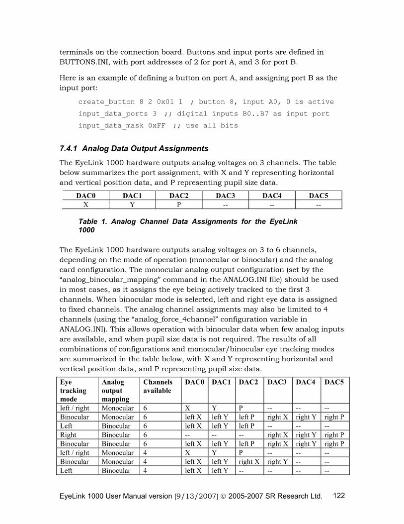
EyeLink 1000 User Manual version (9/13/2007) © 2005-2007 SR Research Ltd. 122
terminals on the connection board. Buttons and input ports are defined in BUTTONS.INI, with port addresses of 2 for port A, and 3 for port B.
Here is an example of defining a button on port A, and assigning port B as the input port:
create_button 8 2 0x01 1 ; button 8, input A0, 0 is active
input_data_ports 3 ;; digital inputs B0..B7 as input port
input_data_mask 0xFF ;; use all bits
7.4.1 Analog Data Output Assignments
The EyeLink 1000 hardware outputs analog voltages on 3 channels. The table below summarizes the port assignment, with X and Y representing horizontal and vertical position data, and P representing pupil size data.
DAC0 DAC1 DAC2 DAC3 DAC4 DAC5 X Y P -- -- --
Table 1. Analog Channel Data Assignments for the EyeLink 1000
The EyeLink 1000 hardware outputs analog voltages on 3 to 6 channels, depending on the mode of operation (monocular or binocular) and the analog card configuration. The monocular analog output configuration (set by the “analog_binocular_mapping” command in the ANALOG.INI file) should be used in most cases, as it assigns the eye being actively tracked to the first 3 channels. When binocular mode is selected, left and right eye data is assigned to fixed channels. The analog channel assignments may also be limited to 4 channels (using the “analog_force_4channel” configuration variable in ANALOG.INI). This allows operation with binocular data when few analog inputs are available, and when pupil size data is not required. The results of all combinations of configurations and monocular/binocular eye tracking modes are summarized in the table below, with X and Y representing horizontal and vertical position data, and P representing pupil size data.
Eye tracking mode
Analog output mapping
Channels available
DAC0 DAC1 DAC2 DAC3 DAC4 DAC5
left / right Monocular 6 X Y P -- -- -- Binocular Monocular 6 left X left Y left P right X right Y right P Left Binocular 6 left X left Y left P -- -- -- Right Binocular 6 -- -- -- right X right Y right P Binocular Binocular 6 left X left Y left P right X right Y right P left / right Monocular 4 X Y P -- -- -- Binocular Monocular 4 left X left Y right X right Y -- -- Left Binocular 4 left X left Y -- -- -- --
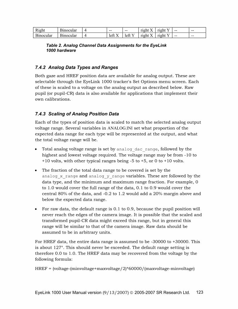
EyeLink 1000 User Manual version (9/13/2007) © 2005-2007 SR Research Ltd. 123
Right Binocular 4 -- -- right X right Y -- -- Binocular Binocular 4 left X left Y right X right Y -- --
Table 2. Analog Channel Data Assignments for the EyeLink 1000 hardware
7.4.2 Analog Data Types and Ranges
Both gaze and HREF position data are available for analog output. These are selectable through the EyeLink 1000 tracker's Set Options menu screen. Each of these is scaled to a voltage on the analog output as described below. Raw pupil (or pupil-CR) data is also available for applications that implement their own calibrations.
7.4.3 Scaling of Analog Position Data
Each of the types of position data is scaled to match the selected analog output voltage range. Several variables in ANALOG.INI set what proportion of the expected data range for each type will be represented at the output, and what the total voltage range will be.
• Total analog voltage range is set by analog_dac_range, followed by the highest and lowest voltage required. The voltage range may be from -10 to +10 volts, with other typical ranges being -5 to +5, or 0 to +10 volts.
• The fraction of the total data range to be covered is set by the analog_x_range and analog_y_range variables. These are followed by the data type, and the minimum and maximum range fraction. For example, 0 to 1.0 would cover the full range of the data, 0.1 to 0.9 would cover the central 80% of the data, and -0.2 to 1.2 would add a 20% margin above and below the expected data range.
• For raw data, the default range is 0.1 to 0.9, because the pupil position will never reach the edges of the camera image. It is possible that the scaled and transformed pupil-CR data might exceed this range, but in general this range will be similar to that of the camera image. Raw data should be assumed to be in arbitrary units.
For HREF data, the entire data range is assumed to be -30000 to +30000. This is about 127°. This should never be exceeded. The default range setting is therefore 0.0 to 1.0. The HREF data may be recovered from the voltage by the following formula:
HREF = (voltage-(minvoltage+maxvoltage/2)*60000/(maxvoltage-minvoltage)
EyeLink 1000 User Manual version (9/13/2007) © 2005-2007 SR Research Ltd. 124
• For gaze position data, the data range is scaled to the display coordinates, which are 640 by 480 at startup, and may be changed via link commands. The data range setting is -0.2 to 1.2, allowing 20% extra range for fixations that map to outside the display. This extra data range allows for slippage or for identification of fixations outside the display. Scaling to recover gaze position data is more complex, as the numerical value is partially dependent on the display coordinates. The following formulas do the conversion in several stages, with R being the voltage range proportion, and S being the proportion of screen width or height.
R = (voltage-minvoltage)/(maxvoltage-minvoltage)
S = R*(maxrange-minrange)+minrange
Xgaze = S*(screenright-screenleft+1)+screenleft
Ygaze = S*(screenbottom-screentop+1)+screentop
7.5 Pupil Size Data
For pupil size, either pupil area or pupil diameter may be monitored. These are very high-resolution measurements, with resolution as small as 5 microns (0.005 mm). Pupil size measurements are affected by eye position, due to the optics of the eye and camera, and should be considered to be measured in arbitrary units, with a pupil size of zero being represented by the lowest analog voltage.
7.6 Timebase and Data Strobe
The EyeLink 1000 eye tracker samples eye position every 0.5, 1, 2 or 4 ms and outputs analog data at 2000, 1000, 500, or 250 hz (depending on your tracker setting and system licensing). This combination of fast sampling rate and non-continuous output differs from most eye-tracking systems with analog outputs, which either output continuous analog data (such as limbus-tracking systems) or output samples at a lower rate, such as 50/60 Hz video-based tracking systems. This causes the EyeLink analog output to rapidly step between data values, which means that sampling at fixed intervals makes it likely that samples might be missed, sampled twice, or the transition between samples might be recorded instead. Since the EyeLink 1000 tracker and most data-acquisition systems rely on interrupt-driven software sampling and output, it is possible that time base jitter could result in missed samples, or repeated recording of a single eye-position sample. This would appear as a "step" artifact in rapidly-changing eye-position data, such as saccades or pursuit.
EyeLink 1000 User Manual version (9/13/2007) © 2005-2007 SR Research Ltd. 125
7.6.1 Strobe Data Input
The best time base method is to use the EyeLink 1000 analog output strobe, which is assigned to digital output D7 on the analog card connection board. This signal can be configured to be a short or long trigger pulse, which can be used to trigger hardware data acquisition on analog input devices equipped for this, or to trigger interrupt-driven acquisition. The characteristics of this strobe pulse may be set in the ANALOG.INI file, with the strobe being active-high or active-low, and with duration between 5 and 2000 microseconds.
The onset of the strobe is also delayed from the time that analog outputs change, in order to allow outputs to settle to the new voltages. A delay of 400 microseconds is standard, allowing the use of signal-conditioning low pass filters as discussed earlier.
7.6.2 Oversampling and Toggle Strobe
Another possibility is to over sample the analog output, by recording the analog outputs at more than twice the EyeLink 1000 sample rate. This will prevent missed samples, but will still result in steps in the data. Recording the digital strobe output (on an analog or digital input channel) in combination with the analog data allows the first data from each sample to be selected, by detecting the change in value of this output. By setting the duration of the strobe pulse to 0, the strobe output can be set to toggle between high (4 to 5 volts) and low (0 to 1 volt) for every sample, which produces the best signal. Over sampling can also be used without the strobe when the analog data is being used to drive a gaze-contingent display, as the time of each sample is unimportant and over sampling will minimizes total data delay.