Embed Size (px)
Citation preview
Eyeclopby Alex Chen
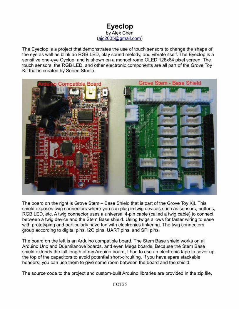
The Eyeclop is a project that demonstrates the use of touch sensors to change the shape of the eye as well as blink an RGB LED, play sound melody, and vibrate itself. The Eyeclop is a sensitive one-eye Cyclop, and is shown on a monochrome OLED 128x64 pixel screen. The touch sensors, the RGB LED, and other electronic components are all part of the Grove Toy Kit that is created by Seeed Studio.
The board on the right is Grove Stem – Base Shield that is part of the Grove Toy Kit. This shield exposes twig connectors where you can plug in twig devices such as sensors, buttons, RGB LED, etc. A twig connector uses a universal 4-pin cable (called a twig cable) to connect between a twig device and the Stem Base shield. Using twigs allows for faster wiring to ease with prototyping and particularly have fun with electronics tinkering. The twig connectors group according to digital pins, I2C pins, UART pins, and SPI pins.
The board on the left is an Arduino compatible board. The Stem Base shield works on all Arduino Uno and Duemilanove boards, and even Mega boards. Because the Stem Base shield extends the full length of my Arduino board, I had to use an electronic tape to cover up the top of the capacitors to avoid potential short-circuiting. If you have spare stackable headers, you can use them to give some room between the board and the shield.
The source code to the project and custom-built Arduino libraries are provided in the zip file,
1 Of 25
and the layout for the file directory structure is also explained at the end of this document.
Part 1 – The Eye of the EyeclopThere is a total of six expressions that the Eyeclop can show: 1) closed, 2) sleepy (slightly opened), 3) opened, 4) looking towards left, 5) looking towards right and 6) dizzy. This part will show how to draw each expression on the OLED screen.
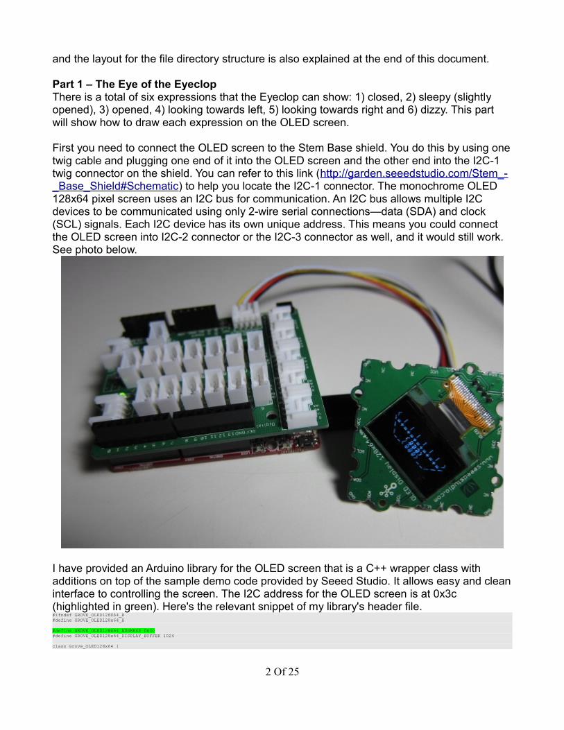
First you need to connect the OLED screen to the Stem Base shield. You do this by using one twig cable and plugging one end of it into the OLED screen and the other end into the I2C-1 twig connector on the shield. You can refer to this link (http://garden.seeedstudio.com/Stem_-_Base_Shield#Schematic) to help you locate the I2C-1 connector. The monochrome OLED 128x64 pixel screen uses an I2C bus for communication. An I2C bus allows multiple I2C devices to be communicated using only 2-wire serial connections—data (SDA) and clock (SCL) signals. Each I2C device has its own unique address. This means you could connect the OLED screen into I2C-2 connector or the I2C-3 connector as well, and it would still work. See photo below.
I have provided an Arduino library for the OLED screen that is a C++ wrapper class with additions on top of the sample demo code provided by Seeed Studio. It allows easy and clean interface to controlling the screen. The I2C address for the OLED screen is at 0x3c (highlighted in green). Here's the relevant snippet of my library's header file.#ifndef GROVE_OLED128X64_H#define GROVE_OLED128x64_H
#define GROVE_OLED128x64_ADDRESS 0x3c#define GROVE_OLED128x64_DISPLAY_BUFFER 1024
class Grove_OLED128x64 {
2 Of 25
[code removed for brevity]
public:
Grove_OLED128x64(); ~Grove_OLED128x64();
void Setup(); // call after Wire.begin() in Setup() of your sketch void Clear();
void On(); void Off();
void SetXY(const unsigned char row, const unsigned char col); void SendStr(const char* string);
void DrawFullScreen(const unsigned char bitmap[]);
void Normal(); void Inverse();
void SetScrollingEffect(ScrollingEffect effect, FrameFreq rate, PageAddr startPage = Page_0, PageAddr endPage = Page_7);
void Scrolling(bool flag); // 1=on, 0=off
// For-level communications void SendCommand(const unsigned char com);
[code removed for brevity]
};
#endif // GROVE_OLED128X64_H
The library's class name is Grove_OLED128x64. Here's the list of what each method does:• Setup – to initialize the OLED screen; called inside Setup() function of your sketch• On – to turn on the display• Off – to turn off the display• SetXY – to position the cursor at xy-coordinate before you call SendStr()• DrawFullScreen – to draw a full bitmap image; size is 1024 bytes (128*8)• Normal – to leave the screen white foreground with black background; this is the default• Inverse – to reverse the screen to black foreground with white background• SetScrollingEffect – to control parts of the screen for scrolling; (caveat: not all tested yet)• Scrolling – to turn scrolling on (arg: 1) or off (arg: 0)• SendCommand – to send low-level commands to the screen device
Due to limited SRAM space on my Arduino board, I have used character fonts to construct each shape of the Eyeclop. You can try to use PROGMEM keyword to store into EEPROM, but you will run out very soon if you do multiple animations at full screen resolution (1024 bytes). For those who are interested in doing bitmaps, please refer to this link (http://en.radzio.dxp.pl/bitmap_converter/). Just create a 128x64 pixels greyscale canvas using your favorite photo editor like GIMP or Photoshop, do your drawings, and then save as a BMP file format. After that, use the bitmap converter to convert your bitmap into a byte array in C code. Pass this byte array into DrawFullScreen() to see it on the screen. You can find two sample demos inside the Grove_OLED128x64 library to show usage of it.
For Eyeclop, here are the shapes using character fonts. These are given as code from my Eyeclop_Eye class definition file (Eyeclop_Eye.cpp). The double slashes “\\” are there to escape the slash “\”. I am not a great artist, but please try your imagination to see the eyelashes and the eyeball.const char* Eyeclop_Eye::m_closedEye[] = { "( )", "\\ /", " \\ /", " \\=+=+=+=+=/", " | | | |"};
const char* Eyeclop_Eye::m_sleepyEye[] = { "( )", "\\ | \\_/ | /", " \\=+=+|@|+=+=/", " \\___|_|___/", ""};
3 Of 25
const char* Eyeclop_Eye::m_openedEye[] = { "( | | | | | | )", "\\=+=+=+=+=+=+=/", " \\ (@@@) /", " \\__(@@@)__/", ""};
const char* Eyeclop_Eye::m_lookedLeftEye[] = { "( | | | | | | )", "\\=+=+=+=+=+=+=/", " \\(@@@) /", " \\@@@)_____/", ""};
const char* Eyeclop_Eye::m_lookedRightEye[] = { "( | | | | | | )", "\\=+=+=+=+=+=+=/", " \\ (@@@)/", " \\_____(@@@/", ""};
const char* Eyeclop_Eye::m_dizzyEye[] = { "( | | | | | | )", "\\=+=+=+=+=+=+=/", " \\~?*(@@@)*?~/", " \\?_(@@@)_?/", ""};
Below is the header file Eyeclop_Eye.h to display the eye shapes.#ifndef EYECLOP_EYE_H#define EYECLOP_EYE_H
// Forward declarationclass Grove_OLED128x64;
class Eyeclop_Eye{public: Eyeclop_Eye(); ~Eyeclop_Eye(); void ShowTitle(Grove_OLED128x64& rLCD);
void Open(Grove_OLED128x64& rLCD); void Close(Grove_OLED128x64& rLCD);
void LookLeft(Grove_OLED128x64& rLCD); void LookRight(Grove_OLED128x64& rLCD); void LookDizzy(Grove_OLED128x64& rLCD); void LookSleepy(Grove_OLED128x64& rLCD);
[code removed for brevity]
};
#endif // EYECLOP_EYE_H
The argument to each method is an object of the OLED screen, which is taken as a reference. This approach allows you to draw the eye on any OLED screen, if you have more than one. This is accomplished by passing in the OLED screen object that is initialized in your main sketch file. Below is a demo code to display all the eye shapes with a 2-second pause between each display.#include "Grove_OLED128x64.h"#include "Eyeclop_Eye.h"#include <Wire.h>
Grove_OLED128x64 gOLED;Eyeclop_Eye gEyeclop;
void setup(){ Wire.begin(); gOLED.Setup(); gEyeclop.ShowTitle(gOLED);}
void loop(){ delay(2000); gEyeclop.Close(gOLED); delay(2000); gEyeclop.LookSleepy(gOLED); delay(2000);
4 Of 25

gEyeclop.Open(gOLED); delay(2000); gEyeclop.LookLeft(gOLED); delay(2000); gEyeclop.LookRight(gOLED); delay(2000); gEyeclop.LookDizzy(gOLED);}
The OLED screen object and the Eyeclop_Eye object are created as global variables as you can see by the blue highlights. OLED screen object needs to be set up via its Setup() method call after the Wire.begin() function call for I2C bus setup as shown in yellow highlight.
See photo below for one of the eye shapes—the left-looked eye shape using character fonts.
Internally, when each eye shape is drawn, it clears the screen. The draw method DrawEye() checks to see if the same eye shape has been drawn. If the same eye shape is about to be drawn, then it does not force a clear on the OLED screen to avoid a screen flicker. The eye shape is drawn at a fixed starting location on the screen and each line of the character string in the eye shape variable (e.g., Eyeclop_Eye::m_openedEye) is successively drawn down the row from the starting location.[from Eyeclop_Eye.h]
private:
enum EyeState { eClosed, eSleepy, eOpened, eLookedRight, eLookedLeft, eDizzy }; EyeState m_eyeState;
[from Eyeclop_Eye.cpp]
void Eyeclop_Eye::DrawEye (const char* pBuffer[], const EyeState eyeState,
5 Of 25
Grove_OLED128x64& rLCD){ if (eyeState != m_eyeState) { m_eyeState = eyeState; rLCD.Clear(); } for (int i = 0; i < 5; i++) { rLCD.SetXY(2 + i, 1); rLCD.SendStr(pBuffer[i]); }}
Part 2 – The Awareness of the EyeclopWhen powered on, the Eyeclop goes to deep sleep for 10 seconds before it becomes “aware” of its surroundings. This state allows the user to stay motionless for 10 seconds and the PIR sensor to stabilize after powering it up before the Eyeclop reacts to human motion. While in this state, the OLED screen will flash from normal to inverse and back every one second while displaying the title of the project (Eyeclop) with its author information (me). When ten seconds are up, the closed eye is shown on the screen.
The awareness sensing of the Eyeclop is done using the PIR motion sensor (http://garden.seeedstudio.com/index.php?title=Twig_-_PIR_Motion_Sensor) that is based on “passive infrared”, thus the name PIR. Passive infrared uses two halves of lenses to compare changes in heat reflection to determine motion. The plastic cap is a Fresnel lens that redirects a wider area into the two smaller half sides of the lenses for better absorption. The sensor can be controlled by two potentiometers:
• one to regulate distance detection• other to regulate how long it should hold in detection state
There is also a switch next to the twig connector that specifies if motion detection can be re-triggered (H position) or not (L position). The H (high) position faces towards the board's edge. For normal practical purposes, H position is desired, because it allows motion detection to be on as long as there is movement being detected. In the L position, it will toggle, because it resets though there is still movement. You need to play around with the potentiometers to have the right settings for your project's needs. Besides giving life to the Eyeclop, this sensor has many other useful applications like for theft-deterrent systems and for scaring away small garden fruit/vegetable-eating animals.
The Eyeclop is a very sensitive creature, so it will be awakened after three counts of disturbances during its sleep. For each disturbance, it will show a sleepy eye for one second before falling back into its slumber. On the PIR motion sensor twig, it has been set to 2 cm proximity and about 2 seconds holding time. Below is the relevant code to give awareness to the Eyeclop.#include "Grove_OLED128x64.h>"#include <Wire.h>#include "Eyeclop_Eye.h"
bool gOnce = false;
Grove_OLED128x64 gOLED;Eyeclop_Eye gEyeclop;int gMotion = 1; // use pin 1 to receive signal outputted by PIR motion sensor
int gDisturbanceCount = 0;
void setup(){ Wire.begin(); gOLED.Setup(); gEyeclop.ShowTitle(gOLED); pinMode(gMotion, INPUT);
}
void loop()
6 Of 25

{ // Part 1 if (! gOnce) { for (int i = 0; i < 10; i++) { delay(1000); if (i % 2 == 0) gOLED.Normal(); else gOLED.Inverse(); } gOLED.Normal(); gOnce = true; // no longer show title of the project } // Part 2 if (gDisturbanceCount < 3) { int sensorValue = digitalRead(gMotion); if(sensorValue == 1) { gDisturbanceCount++; gEyeclop.LookSleepy(gOLED); delay(2000); } else { gEyeclop.Close(gOLED); } } else { gEyeclop.Open(gOLED); }}
Three additional global variables as shown in blue highlights are added: 1) gOnce, 2) gMotion and 3) gDisturbanceCount. Variable gOnce is used to display the project's title for only ten seconds. This is done in a for-loop of ten cycles where even number cycle shows normal OLED screen display and odd number cycle shows inverse OLED screen display. This makes the OLED screen display flash. Variable gDisturbanceCount is used to count how many times the Eyeclop is bothered, and it is incremented inside the same block where gEyeclop.LookSleepy() method call is. The sleepy eye will stay sleepy for two seconds before checking if there is anymore disturbances. If there is no more, then it will close its eye again. Variable gMotion is used to designate the input pin for receiving signals from PIR motion sensor.
The signal for motion detection comes through the yellow wire of the twig cable, and it is attached to the twig connector for Digital IO slot 1. So pin 1 (gMotion variable) needs to be set as input mode as shown in yellow highlight. See photo below with the closed eye and the hookup for PIR motion sensor twig.
Normally, I would highly recommend to leave digital IO pin 1 alone, because it will conflict with
7 Of 25

Serial.begin() when you need Serial.println() for quick debugging. For now, this tutorial does not require serial communications to PC terminal.
Part 3 – Eyeclop Wakes UpAfter three disturbances to the Eyeclop, it wakes up and starts to look left and right before looking straight ahead again. There is a pause of two seconds in between each change of the eye shape. After doing all this, the Eyeclop is now in an awakened state.
The Eyeclop has four sensitive areas that are detected by the touch sensor twig (http://seeedstudio.com/wiki/index.php?title=Twig_-_I2C_Touch_Sensor_v0.93b). The touch sensor twig uses Freescale MPR121 chip to detect up to 12 capacitive touch areas. Each touch area holds a charge level (capacitance) that is affected by finger touch, which grounds it and lowers the charge level. When the capacitance of a touch area is lowered from its default state, the MPR121 chip signals that that touch area has been touched. The MPR121 communicates over I2C bus like the Grove OLED screen. To program the touch sensor twig, you can use polling method or interrupt method, because the MPR121 will give you an interrupt if any of the touch areas has been touched or released. To use interrupt method, you need to solder in a pin onto the interrupt pin slot on the touch sensor twig. In the Eyeclop project, polling method is used instead. A slight disadvantage with polling method is that you need to touch the touch area a bit longer so that the polling will read it at the right time.
Below is my C++ code wrapper that is adapted from source code at http://bildr.org/2011/05/mpr121_arduino/ link to make it easier to use in your sketch.#ifndef GROVE_TOUCHSENSOR#define GROVE_TOUCHSENSOR
#define GROVE_TOUCHSENSOR_ADDRESS 0x5a
// Touch/release threshold values#define GROVE_TOUCHSENSOR_TOUCH_THRESHOLD 0x06#define GROVE_TOUCHSENSOR_TOUCH_RELEASE_THRESHOLD 0x0A
class Grove_TouchSensor{public:
enum TouchState { eNotTouched, eTouched, eStillTouched, eNoLongerTouched }; enum TouchFeeler { eNode0 = 0, eNode1, eNode2, eNode3, eNode4, eNode5, eNode6, eNode7, eNode8, eNode9, eNode10, eNode11, eNode_Count // DO NOT USE; for internal use only }; public:
Grove_TouchSensor(const unsigned char touchThreshold = GROVE_TOUCHSENSOR_TOUCH_THRESHOLD, const unsigned char releaseThreshold = GROVE_TOUCHSENSOR_TOUCH_RELEASE_THRESHOLD); ~Grove_TouchSensor(); void Setup(); // call after Wire.begin() in Setup() of your sketch TouchState GetTouchState(TouchFeeler nodeNum); bool IsTouched(TouchFeeler nodeNum);
[removed for brevity]
};
8 Of 25
#endif // GROVE_TOUCHSENSOR
The touch sensor twig uses 0x5a address for its I2C bus communication as shown in green highlight. When Grove_TouchSensor object is created, it can be initialized with touch threshold value and release threshold value. These values range from 0 to 255, but typical applications will use values from 5 (0x05) to 48 (0x30). You can initialize each touch area with a different touch threshold value and a different release threshold value. These values determine the sensitivity of touch detection and release detection. My Grove_TouchSensor class allows touch threshold value and release threshold value to be passed into the constructor of the class, but it uses the same pair of values for all touch areas. A touch area is called Touch Feeler pad on the Grove Touch Sensor twig, and the C++ class enumerates it as eNode0, eNode2, eNode3, etc. Node eNode0 refers to channel CH0 on the twig; eNode1 refers to channel CH1; and so on. The methods of Grove_TouchSensor class are described below:
• Setup – to initialize the touch sensor with touch threshold value and release threshold value for each Touch Feeler node; called inside Setup() function of your sketch
• GetTouchState – returns eNotTouched if touch is not detected, eTouched if touch is detected, eStillTouched if touch was detected before and is still detected now, and eNoLongerTouched if touch was detected before but is not now
• IsTouched – returns a boolean value true if touch state is either eTouched or eStillTouched else eNotTouched
Both methods GetTouchState() and IsTouched() take one argument each that is the Touch Feeler node number.
Grove Touch Sensor twig is connected to the I2C-2 slot on the Stem Base shield using the twig cable. If you replug a Touch Feeler pad into a different channel on the touch sensor twig, you will need to reset the power of your Arduino, because the MPR121 chip does auto-configure on power up and the touch sensor twig itself does not provide its own power reset. See photo below.
9 Of 25
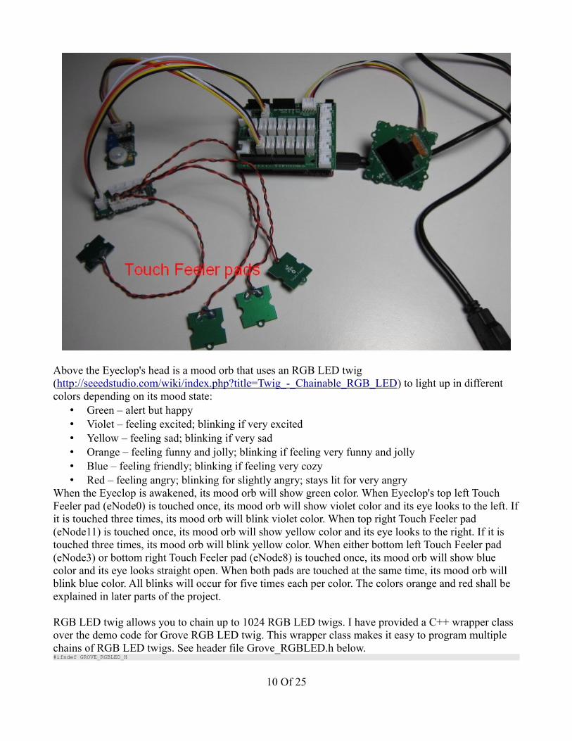
Above the Eyeclop's head is a mood orb that uses an RGB LED twig (http://seeedstudio.com/wiki/index.php?title=Twig_-_Chainable_RGB_LED) to light up in different colors depending on its mood state:
• Green – alert but happy• Violet – feeling excited; blinking if very excited• Yellow – feeling sad; blinking if very sad• Orange – feeling funny and jolly; blinking if feeling very funny and jolly• Blue – feeling friendly; blinking if feeling very cozy• Red – feeling angry; blinking for slightly angry; stays lit for very angry
When the Eyeclop is awakened, its mood orb will show green color. When Eyeclop's top left Touch Feeler pad (eNode0) is touched once, its mood orb will show violet color and its eye looks to the left. If it is touched three times, its mood orb will blink violet color. When top right Touch Feeler pad (eNode11) is touched once, its mood orb will show yellow color and its eye looks to the right. If it is touched three times, its mood orb will blink yellow color. When either bottom left Touch Feeler pad (eNode3) or bottom right Touch Feeler pad (eNode8) is touched once, its mood orb will show blue color and its eye looks straight open. When both pads are touched at the same time, its mood orb will blink blue color. All blinks will occur for five times each per color. The colors orange and red shall be explained in later parts of the project.
RGB LED twig allows you to chain up to 1024 RGB LED twigs. I have provided a C++ wrapper class over the demo code for Grove RGB LED twig. This wrapper class makes it easy to program multiple chains of RGB LED twigs. See header file Grove_RGBLED.h below.#ifndef GROVE_RGBLED_H
10 Of 25
#define GROVE_RGBLED_H
class Grove_RGBLED{public:
typedef unsigned long long RGB_t;
public:
Grove_RGBLED(const unsigned int clockPin, const unsigned int dataPin); ~Grove_RGBLED(); void Setup(); // call in Setup() of your sketch
void Off(); // turns color off Grove_RGBLED& StartChain(); void StopChain(); RGB_t MakeRGBColor(const unsigned char r, const unsigned char g, const unsigned char b); Grove_RGBLED& SetColor(const unsigned char r, const unsigned char g, const unsigned char b); Grove_RGBLED& SetColor(const RGB_t rgb);
[removed for brevity]
};
#endif // GROVE_RGBLED_H
The methods of Grove_RGBLED class are as follows:• Grove_RGBLED – constructs the Grove_RGBLED object with two arguments passed in: a)
digital IO pin for clock signal and b) digital IO pin for data signal• Setup – to initialize the RGB LED twig; called inside Setup() function of your sketch• StartChain – starts the chain for setting colors on the RGB LED chain• StopChain – stops the chain to display the color• SetColor – sets the color in the RGB LED chain with two methods: a) using individual RGB
values and b) using one 32-bit RGB value where the MSB is not used• Off – turns color off for one RGB LED twig• MakeRGBColor – accepts individual RGB values returns one 32-bit RGB value
MakeRGBColor() method is provided for convenience when you want to store the RGB value into one variable. StartChain() and SetColor() methods return back the RGB LED object itself so you can successively call it again with SetColor() to specify the next color in the RGB LED twig chain. Just like you do with chaining up the RGB LED twigs! Below is an example demo using my wrapper class that shows red, green, blue, violet, yellow, and orange colors with one second delay between each color change.#include "Grove_RGBLED.h"
Grove_RGBLED gLED(3, 4);
void setup(){ gLED.Setup();}
void loop(){ gLED.StartChain().SetColor(255,0,0).StopChain(); // red delay(1000); gLED.StartChain().SetColor(0,255,0).StopChain(); // green delay(1000); gLED.StartChain().SetColor(0,0,255).StopChain(); // blue delay(1000); Grove_RGBLED::RGB_t voilet = gLED.MakeRGBColor(148,0,211); // violet gLED.StartChain().SetColor(violet).StopChain(); delay(1000); gLED.StartChain().SetColor(255,255,0).StopChain(); // yellow delay(1000); gLED.StartChain().SetColor(255,127,0).StopChain(); // orange delay(1000);}
Here the RGB LED twig is using digital IO pin 3 for clock and digital IO pin 4 for data as shown in blue highlight. The direction of the pins are set as OUTPUT inside the Setup() method call of the RGB LED object as shown in yellow highlight. To set the colors of the RGB LED chain, you can do this in
11 Of 25

your code:void loop(){ Grove_RGBLED::RGB_t voilet = gLED.MakeRGBColor(148,0,211); // violet gLED.StartChain().SetColor(255,0,0).SetColor(0,255,0).SetColor(0,0,255).SetColor(violet).SetColor(255,255,0).SetColor(255,127,0).StopChain(); // show red, green, blue, violet, yellow, orange in a row delay(5000);
// gLED.StartChain().SetColor(255,0,0).Off().SetColor(0,0,255).StopChain();}
The above code will set the first RGB LED twig in the chain to red; second RGB LED twig in the chain to blue; etc. Remember to always call StartChain() method first before setting any colors and then finally call StopChain() method to end the chain and start the LED chain displays.
Now let's get back to combining the touch sensor twig and the RGB LED twig to display the Eyeclop's moods. Let's create supporting functions to help in coding and reduce code clutter.void TurnOffLED (){ gLED.StartChain().Off().StopChain();}
void TurnOnLEDColor (const Grove_RGBLED::RGB_t color){ gLED.StartChain().SetColor(color).StopChain();}
void BlinkLEDColor (const Grove_RGBLED::RGB_t color, const unsigned char num){ unsigned char i = 0; for (; i < num; ++i) { TurnOnLEDColor(color); delay(1000); TurnOffLED(); delay(1000); }}
void MakeMood (const Grove_RGBLED::RGB_t color){ if (gPrevColor == color) { gTouchCount++; } else { gPrevColor = color; gTouchCount = 1; } if (gTouchCount >= 3) { BlinkLEDColor(color, 5); } else { TurnOnLEDColor(color); delay(2000); }}
TurnOffLED() function is to turn off the LED. The LED needs to be turned off else it will remember from previous color setting. TurnOnLEDColor() function sets the mood orb (RGB LED twig) to any color passed in as argument. BlinkLEDColor() function will blink the LED using the input color for five times. MakeMood() function is responsible for counting how many times the same color has been shown. If a touch pad has been touched for at least three times in a row, then it blinks that color for five times. Else, it blinks that color for two seconds. MakeMood() function is important, because it will be used inside the code block for the top left and right touch pads.
Below is the code to give the Eyeclop its moods that react to touch sensing.#include "Grove_OLED128x64.h"#include "Grove_TouchSensor.h"#include "Grove_RGBLED.h"#include <Wire.h>#include "Eyeclop_Eye.h"
// Forward declarationsvoid TurnOffLED();void TurnOnLEDColor(const Grove_RGBLED::RGB_t color);void BlinkLEDColor(const Grove_RGBLED::RGB_t color, const unsigned char num);void MakeMood(const Grove_RGBLED::RGB_t color);
12 Of 25

bool gOnce = false;bool gAwakened = false;
Grove_OLED128x64 gOLED;Grove_TouchSensor gTouchSensor;Grove_RGBLED gLED(3, 4);Eyeclop_Eye gEyeclop;int gMotion = 1; // use pin 1 to receive signal outputted by PIR motion sensor
int gDisturbanceCount = 0;Grove_RGBLED::RGB_t gRedColor, gGreenColor, gBlueColor, gVioletColor, gYellowColor, gOrangeColor;Grove_RGBLED::RGB_t gPrevColor = 0;int gTouchCount = 0;
void setup(){ Wire.begin(); gOLED.Setup(); gEyeclop.ShowTitle(gOLED); pinMode(gMotion, INPUT); gTouchSensor.Setup(); gLED.Setup(); gRedColor = gLED.MakeRGBColor(255,0,0); gGreenColor = gLED.MakeRGBColor(0,255,0); gBlueColor = gLED.MakeRGBColor(0,0,255); gVioletColor = gLED.MakeRGBColor(148,0,211); gYellowColor = gLED.MakeRGBColor(255,255,0); gOrangeColor = gLED.MakeRGBColor(255,127,0);}
void loop(){ // Part 1 - The Eye of the Eyeclop if (! gOnce) { TurnOffLED(); for (int i = 0; i < 10; i++) { delay(1000); if (i % 2 == 0) gOLED.Normal(); else gOLED.Inverse(); } gOLED.Normal(); gOnce = true; // no longer show title of the project } // Part 2 - The Awareness of the Eyeclop if (gDisturbanceCount < 3) { int sensorValue = digitalRead(gMotion); if(sensorValue == 1) { gDisturbanceCount++; gEyeclop.LookSleepy(gOLED); delay(2000); } else { gEyeclop.Close(gOLED); } } else { // Part 3 - Eyeclop Wakes Up and looks around if (! gAwakened) { gEyeclop.Open(gOLED); delay(2000); gEyeclop.LookLeft(gOLED); delay(2000); gEyeclop.LookRight(gOLED); delay(2000); gEyeclop.Open(gOLED); delay(1000); gAwakened = true; } } // Part 3 - Eyeclop Wakes Up and is ready to receive touchy feelings if (gAwakened) { TurnOnLEDColor(gGreenColor); if (gTouchSensor.IsTouched(Grove_TouchSensor::eNode0)) { gEyeclop.LookLeft(gOLED); delay(1000); gOLED.Inverse(); delay(1000); gOLED.Normal(); MakeMood(gVioletColor); } else if (gTouchSensor.IsTouched(Grove_TouchSensor::eNode11)) { gEyeclop.LookRight(gOLED); delay(1000); gOLED.Inverse(); delay(1000); gOLED.Normal(); MakeMood(gYellowColor); } else if (gTouchSensor.IsTouched(Grove_TouchSensor::eNode3) && gTouchSensor.IsTouched(Grove_TouchSensor::eNode8)) {
13 Of 25
gPrevColor = 0; gTouchCount = 0; gOLED.Inverse(); delay(1000); gOLED.Normal(); BlinkLEDColor(gBlueColor, 5); } else if (gTouchSensor.IsTouched(Grove_TouchSensor::eNode3) || gTouchSensor.IsTouched(Grove_TouchSensor::eNode8)) { gPrevColor = 0; gTouchCount = 0; gOLED.Inverse(); delay(1000); gOLED.Normal(); TurnOnLEDColor(gBlueColor); delay(2000); } // Back to default eye shape gEyeclop.Open(gOLED); }}
Highlighted in blue are objects that need to be created globally. RGB LED object is initialized with digital IO pin 3 for clock signal and digital IO pin 4 for data signal. The RGB LED twig is connected to the twig connector for Digital IO Port 3 on the Grove Stem Base shield. Variables gPrevColor for previous color and gTouchCount are initialized to zero. In Setup() method, touch sensor object and RGB LED object get set up while the color variables are set their RGB color values. As you can see here, the use of 32-bit RGB value makes it convenient for future references in the code.
When the Eyeclop is powered on, it makes sure that its mood orb is turned off. When it is awakened after three counts of disturbances, its mood orb turns green to indicate an alert and happy state, and its sensitive pads are ready to receive human touches. MakeMood() method is called for top left and right touch pads (eNode0 and eNode11, respectively) with each respective color (violet or yellow). The code checks for both bottom left and right touch pads first before checking either of them, because the and-case (&&) needs to go before the or-case (||). For bottom left and right touch pads, the variables for previous color and the touch count are reset to zero, because the top left and right touch pads require three consecutive touches to enter its mood state. The default eye is the open eye. See photo below where the Eyeclop is in excited mood.
14 Of 25

Part 4 – Eyeclop Can Hear YouBesides being a sensitive one-eye creature with touchy feelings and mood swings, the Eyeclop can hear you and acknowledge you by blinking its mood orb in green light for two times. Unfortunately, its hearing is not too sharp so you have to speak a bit louder and closer. To detect sounds, a sound sensor twig (http://seeedstudio.com/wiki/index.php?title=Twig_-_Sound_Sensor) is used that contains a LM386 power amplifier to strengthen the electronic signal produced by the electret microphone and a potentiometer to regulate the gain. Turning the potentiometer clockwise will increase the gain level for the microphone, which means it will be more sensitive to surrounding sounds. For easy tuning, it is easier to use Serial.println() to write the outputs to the serial terminal while you adjust the gain level. Below is the sample code that reads the value from the sensor and waits for 2.5 seconds before telling you to say something again.void setup(){ Serial.begin(9600);}
void loop(){ int sensorValue = analogRead(A0); //use A0 to read the electrical signal Serial.println(sensorValue); delay(2500); // 2.5 seconds Serial.println("say something"); delay(750); // 750 ms}
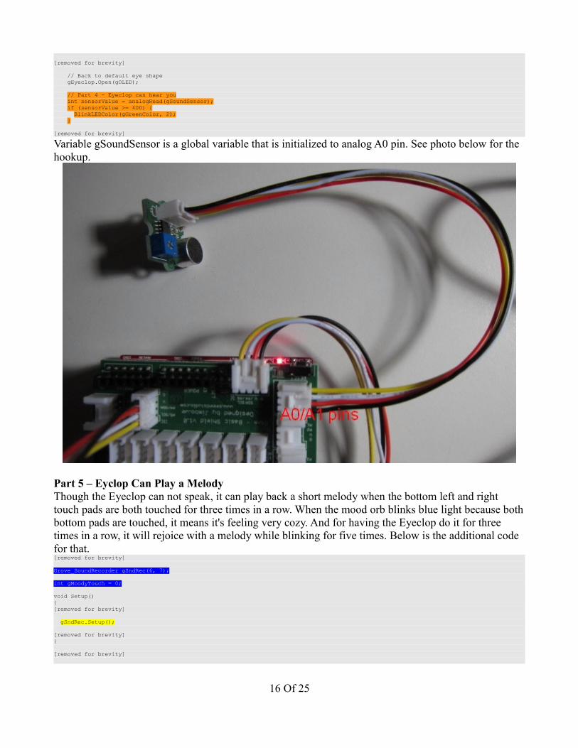
The sensor value is the threshold value that you want to use in your sketch to determine when sounds become audible in your project. Plug the sound sensor twig into the A0/A1 twig connector next to the reset button on the Base Stem shield. Remember the signal wire is the yellow wire on the twig cable. Below is the additional code to the Eyeclop.[removed for brevity]
int gSoundSensor = A0; //use A0 to read the electrical signal
15 Of 25
[removed for brevity]
// Back to default eye shape gEyeclop.Open(gOLED); // Part 4 - Eyeclop can hear you int sensorValue = analogRead(gSoundSensor); if (sensorValue >= 400) { BlinkLEDColor(gGreenColor, 2); }
[removed for brevity]
Variable gSoundSensor is a global variable that is initialized to analog A0 pin. See photo below for the hookup.
Part 5 – Eyclop Can Play a MelodyThough the Eyeclop can not speak, it can play back a short melody when the bottom left and right touch pads are both touched for three times in a row. When the mood orb blinks blue light because both bottom pads are touched, it means it's feeling very cozy. And for having the Eyeclop do it for three times in a row, it will rejoice with a melody while blinking for five times. Below is the additional code for that.[removed for brevity]
Grove_SoundRecorder gSndRec(6, 7);
int gMoodyTouch = 0;
void Setup(){[removed for brevity]
gSndRec.Setup();
[removed for brevity]}
[removed for brevity]
16 Of 25
} else if (gTouchSensor.IsTouched(Grove_TouchSensor::eNode3) && gTouchSensor.IsTouched(Grove_TouchSensor::eNode8)) { gPrevColor = 0; gTouchCount = 0; gOLED.Inverse(); delay(1000); gOLED.Normal(); // Part 5 - Eyeclop can play a melody gMoodyTouch++; if (gMoodyTouch >=3) { gSndRec.PlaySegment(Grove_SoundRecorder::eSegment2); BlinkLEDColor(gOrangeColor, 5); gMoodyTouch = 0; } else { BlinkLEDColor(gBlueColor, 5); } }
[removed for brevity]
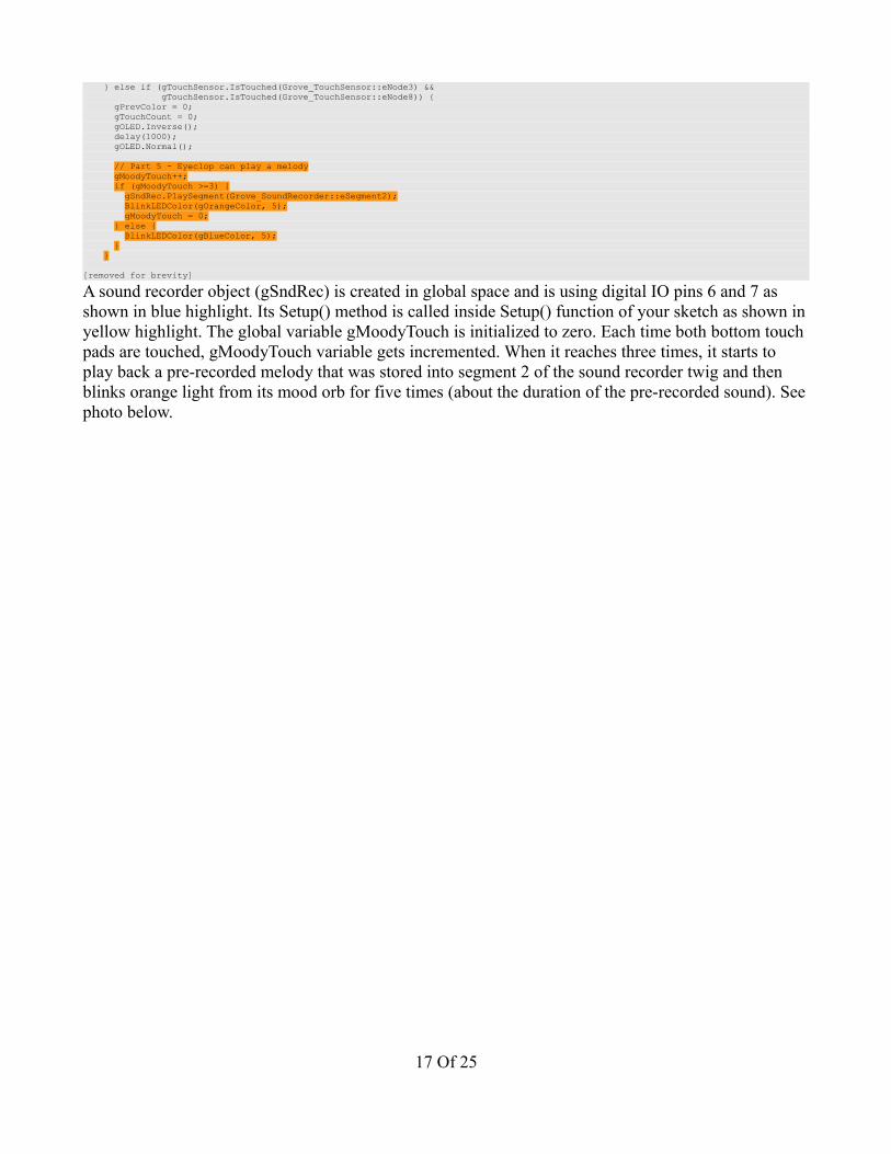
A sound recorder object (gSndRec) is created in global space and is using digital IO pins 6 and 7 as shown in blue highlight. Its Setup() method is called inside Setup() function of your sketch as shown in yellow highlight. The global variable gMoodyTouch is initialized to zero. Each time both bottom touch pads are touched, gMoodyTouch variable gets incremented. When it reaches three times, it starts to play back a pre-recorded melody that was stored into segment 2 of the sound recorder twig and then blinks orange light from its mood orb for five times (about the duration of the pre-recorded sound). See photo below.
17 Of 25
The sound recorder twig is connected to the Digital IO 6 slot on the Stem Base shield.
I have provided a C++ class to make it easy to interface with the sound recorder twig. Below is the header file Grove_SoundRecorder.h.#ifndef GROVE_SOUNDRECORDER_H#define GROVE_SOUNDRECORDER_H
class Grove_SoundRecorder{public:
enum SoundSegment { eSegment2 = 0x01, eSegment3 = 0x02, eSegment4 = 0x03 }; public:
// Works with digital IO pins 0 to 7 only (PORTD)
18 Of 25

Grove_SoundRecorder(const unsigned int sel1Pin, const unsigned int sel2Pin); ~Grove_SoundRecorder(); void Setup(); // call in Setup() of your sketch
// Recording works with SW to REC void StartSegmentRecord(SoundSegment segNum); void StopSegmentRecord(); // Playback works with SW to PLAY void PlaySegment(SoundSegment segNum);
[removed for brevity]
};
#endif // GROVE_SOUNDRECORDER_H
The constructor Grove_SoundRecorder takes in two arguments to specify the two digital IO pins that will be used to control it. Currently, the class is made to work for digital IO pins 0 to 7, but it can be easily extended to work with pins 8 to 13. Calling Setup() inside Setup() of your sketch is to initialize the directions of the pins and clearing them. Because the sound recorder twig has a switch that is not programmable through Arduino, you can only either record sounds or play back sounds but not do both. The sound recorder has four segments to store up to 15 seconds of sound each, but segment 1 is not accessible via Arduino. However, you can access segment 1 by interacting it manually and not programmatically.
Part 6 – The Eyeclop With 3D SensesThough the Eyeclop is a touchy sensitive creature, it does not like to be moved around. If it is picked up and is moved around slightly, then it will start to blink red light twice to warn you. If you start to shake it harder, then it will beep constant unpleasant high-pitch tone, vibrate at the same time, keep the red light lit in its mood orb, and show a dizzy eye look. To detect 3D motion, the Eyeclop uses a 3-axis accelerometer twig (http://seeedstudio.com/wiki/index.php?title=Twig_-_I2C_3-axis_Accelerometer) that is communicated over I2C bus. The 3-axis accelerometer twig is based on Freescale MMA7660FC chip, which is a very low power, low profile capacitive MEMS sensor. MEMS is a micro-electro-mechanical systems which can be of several technologies. This one uses a metal beam that produces capacitance while a piezoelectric one houses a mass suspended by springs on all sides of the inside cube. Moving the MEMS around affect the relative changes in capacitance or voltage (for suspended mass). The changes in capacitance or voltage then translate to the affects in gravitational pull, measured in g value. The 3-axis accelerometer twig can measure up to +/-1.5g. The higher the g range, the stronger the force (impact) against gravity can be determined. Standing still on the ground has the effect of 1g, so this accelerometer sensor has very miniscule measurements. The Freescale MM7660FC chip also has built-in features for shake, tap, or orientation detection using its low-pass filter. You can receive these signals via an interrupt pin that needs to be soldered in on the twig board.
Because I ran out of I2C slots on the Stem Base shield (and that my I2C-3 slot has analog A4/A5 pins swapped so they won't match the twig cable), I am connecting the accelerometer twig with its twig cable directly to the Arduino headers using male-to-male jumper wires. The outer yellow wire goes to analog A5 pin and the white wire goes to analog A4 pin. The red wire goes to the 5v pin and the black wire goes to GND pin. See photo below.
19 Of 25
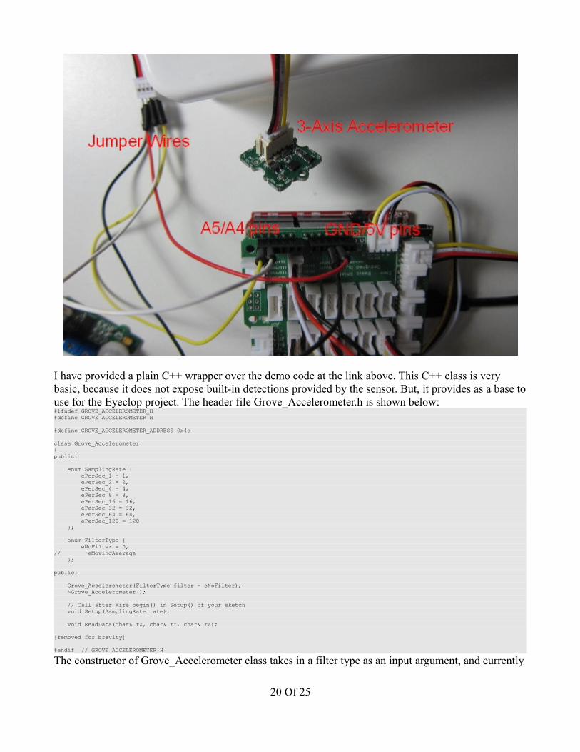
I have provided a plain C++ wrapper over the demo code at the link above. This C++ class is very basic, because it does not expose built-in detections provided by the sensor. But, it provides as a base to use for the Eyeclop project. The header file Grove_Accelerometer.h is shown below:#ifndef GROVE_ACCELEROMETER_H#define GROVE_ACCELEROMETER_H
#define GROVE_ACCELEROMETER_ADDRESS 0x4c
class Grove_Accelerometer{public:
enum SamplingRate { ePerSec_1 = 1, ePerSec_2 = 2, ePerSec_4 = 4, ePerSec_8 = 8, ePerSec_16 = 16, ePerSec_32 = 32, ePerSec_64 = 64, ePerSec_120 = 120 }; enum FilterType { eNoFilter = 0,// eMovingAverage }; public:
Grove_Accelerometer(FilterType filter = eNoFilter); ~Grove_Accelerometer(); // Call after Wire.begin() in Setup() of your sketch void Setup(SamplingRate rate); void ReadData(char& rX, char& rY, char& rZ);
[removed for brevity]
#endif // GROVE_ACCELEROMETER_H
The constructor of Grove_Accelerometer class takes in a filter type as an input argument, and currently
20 Of 25
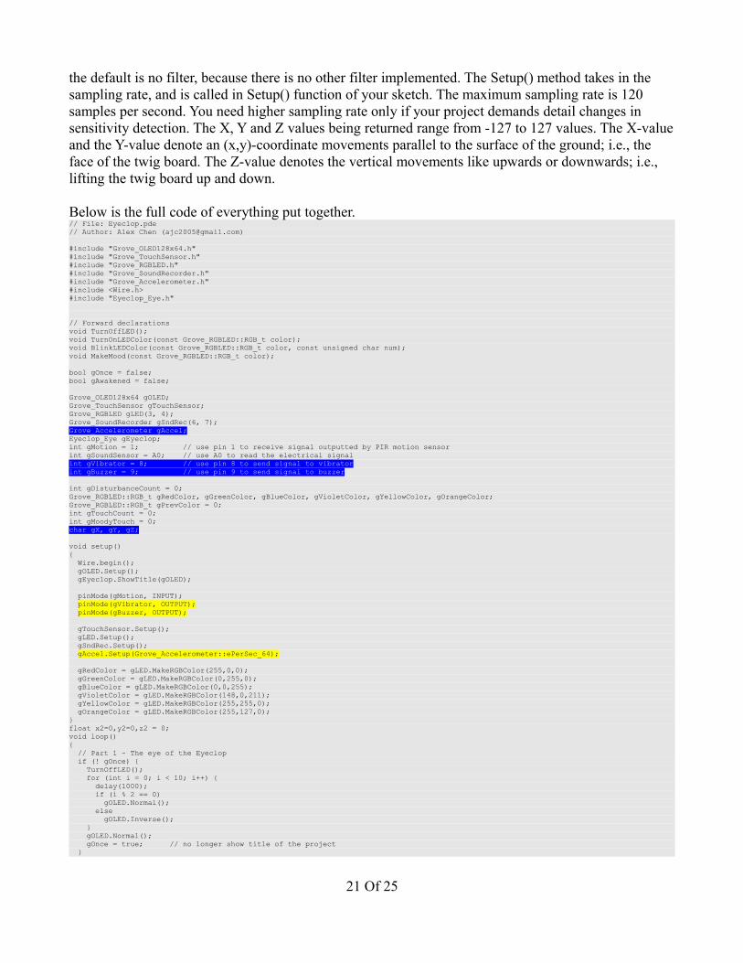
the default is no filter, because there is no other filter implemented. The Setup() method takes in the sampling rate, and is called in Setup() function of your sketch. The maximum sampling rate is 120 samples per second. You need higher sampling rate only if your project demands detail changes in sensitivity detection. The X, Y and Z values being returned range from -127 to 127 values. The X-value and the Y-value denote an (x,y)-coordinate movements parallel to the surface of the ground; i.e., the face of the twig board. The Z-value denotes the vertical movements like upwards or downwards; i.e., lifting the twig board up and down.
Below is the full code of everything put together.// File: Eyeclop.pde// Author: Alex Chen ([email protected])
#include "Grove_OLED128x64.h"#include "Grove_TouchSensor.h"#include "Grove_RGBLED.h"#include "Grove_SoundRecorder.h"#include "Grove_Accelerometer.h"#include <Wire.h>#include "Eyeclop_Eye.h"
// Forward declarationsvoid TurnOffLED();void TurnOnLEDColor(const Grove_RGBLED::RGB_t color);void BlinkLEDColor(const Grove_RGBLED::RGB_t color, const unsigned char num);void MakeMood(const Grove_RGBLED::RGB_t color);
bool gOnce = false;bool gAwakened = false;
Grove_OLED128x64 gOLED;Grove_TouchSensor gTouchSensor;Grove_RGBLED gLED(3, 4);Grove_SoundRecorder gSndRec(6, 7);Grove_Accelerometer gAccel;Eyeclop_Eye gEyeclop;int gMotion = 1; // use pin 1 to receive signal outputted by PIR motion sensorint gSoundSensor = A0; // use A0 to read the electrical signalint gVibrator = 8; // use pin 8 to send signal to vibratorint gBuzzer = 9; // use pin 9 to send signal to buzzer
int gDisturbanceCount = 0;Grove_RGBLED::RGB_t gRedColor, gGreenColor, gBlueColor, gVioletColor, gYellowColor, gOrangeColor;Grove_RGBLED::RGB_t gPrevColor = 0;int gTouchCount = 0;int gMoodyTouch = 0;char gX, gY, gZ;
void setup(){ Wire.begin(); gOLED.Setup(); gEyeclop.ShowTitle(gOLED); pinMode(gMotion, INPUT); pinMode(gVibrator, OUTPUT); pinMode(gBuzzer, OUTPUT); gTouchSensor.Setup(); gLED.Setup(); gSndRec.Setup(); gAccel.Setup(Grove_Accelerometer::ePerSec_64); gRedColor = gLED.MakeRGBColor(255,0,0); gGreenColor = gLED.MakeRGBColor(0,255,0); gBlueColor = gLED.MakeRGBColor(0,0,255); gVioletColor = gLED.MakeRGBColor(148,0,211); gYellowColor = gLED.MakeRGBColor(255,255,0); gOrangeColor = gLED.MakeRGBColor(255,127,0);}float x2=0,y2=0,z2 = 0;void loop(){ // Part 1 - The eye of the Eyeclop if (! gOnce) { TurnOffLED(); for (int i = 0; i < 10; i++) { delay(1000); if (i % 2 == 0) gOLED.Normal(); else gOLED.Inverse(); } gOLED.Normal(); gOnce = true; // no longer show title of the project }
21 Of 25
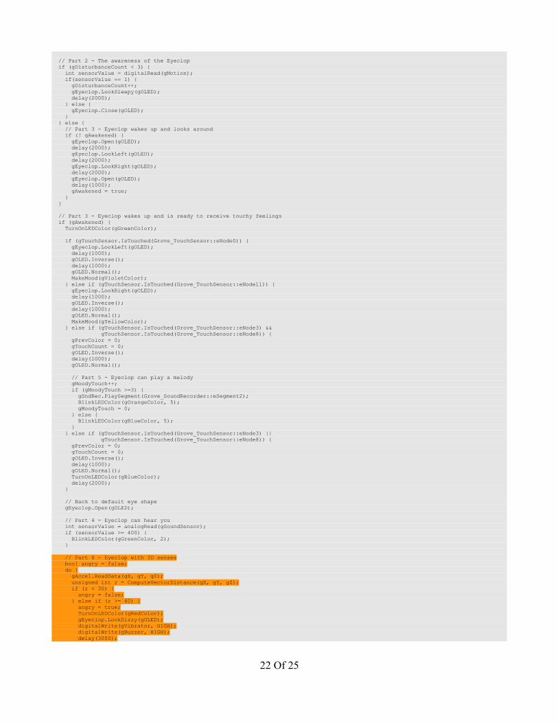
// Part 2 - The awareness of the Eyeclop if (gDisturbanceCount < 3) { int sensorValue = digitalRead(gMotion); if(sensorValue == 1) { gDisturbanceCount++; gEyeclop.LookSleepy(gOLED); delay(2000); } else { gEyeclop.Close(gOLED); } } else { // Part 3 - Eyeclop wakes up and looks around if (! gAwakened) { gEyeclop.Open(gOLED); delay(2000); gEyeclop.LookLeft(gOLED); delay(2000); gEyeclop.LookRight(gOLED); delay(2000); gEyeclop.Open(gOLED); delay(1000); gAwakened = true; } } // Part 3 - Eyeclop wakes up and is ready to receive touchy feelings if (gAwakened) { TurnOnLEDColor(gGreenColor); if (gTouchSensor.IsTouched(Grove_TouchSensor::eNode0)) { gEyeclop.LookLeft(gOLED); delay(1000); gOLED.Inverse(); delay(1000); gOLED.Normal(); MakeMood(gVioletColor); } else if (gTouchSensor.IsTouched(Grove_TouchSensor::eNode11)) { gEyeclop.LookRight(gOLED); delay(1000); gOLED.Inverse(); delay(1000); gOLED.Normal(); MakeMood(gYellowColor); } else if (gTouchSensor.IsTouched(Grove_TouchSensor::eNode3) && gTouchSensor.IsTouched(Grove_TouchSensor::eNode8)) { gPrevColor = 0; gTouchCount = 0; gOLED.Inverse(); delay(1000); gOLED.Normal(); // Part 5 - Eyeclop can play a melody gMoodyTouch++; if (gMoodyTouch >=3) { gSndRec.PlaySegment(Grove_SoundRecorder::eSegment2); BlinkLEDColor(gOrangeColor, 5); gMoodyTouch = 0; } else { BlinkLEDColor(gBlueColor, 5); } } else if (gTouchSensor.IsTouched(Grove_TouchSensor::eNode3) || gTouchSensor.IsTouched(Grove_TouchSensor::eNode8)) { gPrevColor = 0; gTouchCount = 0; gOLED.Inverse(); delay(1000); gOLED.Normal(); TurnOnLEDColor(gBlueColor); delay(2000); } // Back to default eye shape gEyeclop.Open(gOLED); // Part 4 - Eyeclop can hear you int sensorValue = analogRead(gSoundSensor); if (sensorValue >= 400) { BlinkLEDColor(gGreenColor, 2); } // Part 6 - Eyeclop with 3D senses bool angry = false; do { gAccel.ReadData(gX, gY, gZ); unsigned int r = ComputeVectorDistance(gX, gY, gZ); if (r < 30) { angry = false; } else if (r >= 40) { angry = true; TurnOnLEDColor(gRedColor); gEyeclop.LookDizzy(gOLED); digitalWrite(gVibrator, HIGH); digitalWrite(gBuzzer, HIGH); delay(3000);
22 Of 25
} else if (r >= 30) { BlinkLEDColor(gRedColor, 3); } } while (angry); // Go back to calm state digitalWrite(gVibrator, LOW); digitalWrite(gBuzzer, LOW); gEyeclop.Open(gOLED); TurnOnLEDColor(gGreenColor); }}
void TurnOffLED (){ gLED.StartChain().Off().StopChain();}
void TurnOnLEDColor (const Grove_RGBLED::RGB_t color){ gLED.StartChain().SetColor(color).StopChain();}
void BlinkLEDColor (const Grove_RGBLED::RGB_t color, const unsigned char num){ unsigned char i = 0; for (; i < num; ++i) { TurnOnLEDColor(color); delay(1000); TurnOffLED(); delay(1000); }}
void MakeMood (const Grove_RGBLED::RGB_t color){ if (gPrevColor == color) { gTouchCount++; } else { gPrevColor = color; gTouchCount = 1; } if (gTouchCount >= 3) { BlinkLEDColor(color, 5); } else { TurnOnLEDColor(color); delay(2000); }}
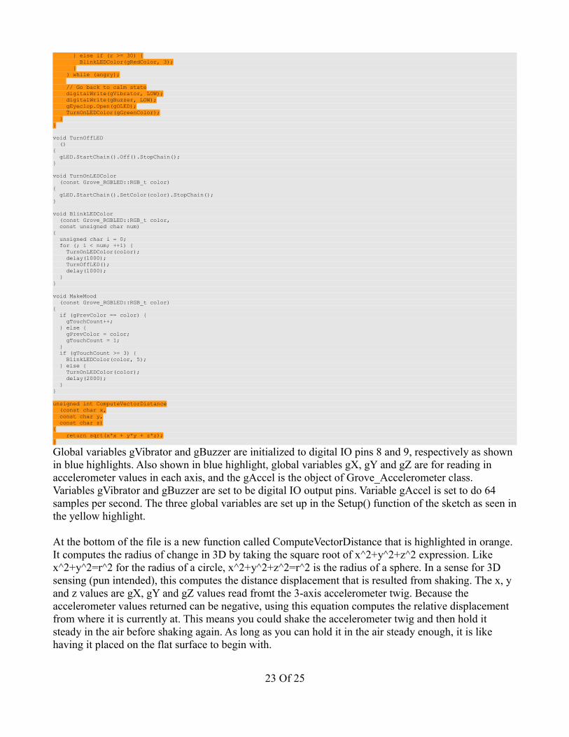
unsigned int ComputeVectorDistance (const char x, const char y, const char z){ return sqrt(x*x + y*y + z*z);}
Global variables gVibrator and gBuzzer are initialized to digital IO pins 8 and 9, respectively as shown in blue highlights. Also shown in blue highlight, global variables gX, gY and gZ are for reading in accelerometer values in each axis, and the gAccel is the object of Grove_Accelerometer class. Variables gVibrator and gBuzzer are set to be digital IO output pins. Variable gAccel is set to do 64 samples per second. The three global variables are set up in the Setup() function of the sketch as seen in the yellow highlight.
At the bottom of the file is a new function called ComputeVectorDistance that is highlighted in orange. It computes the radius of change in 3D by taking the square root of x^2+y^2+z^2 expression. Like x^2+y^2=r^2 for the radius of a circle, x^2+y^2+z^2=r^2 is the radius of a sphere. In a sense for 3D sensing (pun intended), this computes the distance displacement that is resulted from shaking. The x, y and z values are gX, gY and gZ values read fromt the 3-axis accelerometer twig. Because the accelerometer values returned can be negative, using this equation computes the relative displacement from where it is currently at. This means you could shake the accelerometer twig and then hold it steady in the air before shaking again. As long as you can hold it in the air steady enough, it is like having it placed on the flat surface to begin with.
23 Of 25

From my experiments, a value of r (for radius) greater than 30 is considered non-shaking. A value of r greater than or equal to 30 but less than 40 is considered mild shaking whereas anything equal or above 40 is considered heavy shaking. In heavy shaking, the Eyeclop's mood orb will light red and the Eyeclop will make a high-pitch tone and vibrate itself for three seconds. It does it this way to make you leave it alone! It's touchy, but it does not want to be picked up! Slight shaking will cause its mood orb to blink red color three times to warn you.
That's all, and I hope you enjoy the Eyeclop as I do. Final photo of everything hooked up below.
YouTube video is available at http://www.youtube.com/watch?v=AjtvoA2FFAs link.
Contents of Zip FileThe zip file contains all the custom Arduino libraries provided by me and the Eyeclop project files. Below is the layout of the directory structure:
• Eyeclop_howto.pdf – this step-by-step instruction document• Arduino – folder of your sketches
◦ Eyeclop – contains the main Eyeclop sketch and the Eyeclop_Eye header and class files◦ libraries – folder contains custom-built libraries for the Eyelcop project
▪ Grove_Accelerometer – folder contains the C++ header and class files▪ Grove_SoundRecorder – folder contains the C++ header and class files▪ Grove_RGBLED – folder contains the C++ header and class files▪ Grove_TouchSensor – folder contains the C++ header and class files▪ Grove_OLED128x64 – folder contains the C++ header and class files
24 Of 25

• examples – folder contains two sample demos◦ Sample1 – sample demo1◦ Sample2 – sample demo2
25 Of 25


![[PPT]Slide 1 - International Maritime Statistics Forum | IMSF · Web viewSARA PRIMA IBZK SARGODHA AQOK SCAN WMDZ SCL BERN HBEG SCL ELISE A8MT9 SCL MARGRIT A8MT8 SCL MARIE-JEANNE A8MT7](https://img.pdfslide.us/doc/110x75/5ae6f8ea7f8b9a3d3b8de400/pptslide-1-international-maritime-statistics-forum-viewsara-prima-ibzk-sargodha.jpg)