Embed Size (px)
Citation preview

Eye Tracking System Instruction Manual
Model 504Pan/Tilt Optics
M A N U A L V E R S I O N 2 . 4

Applied Science Laboratories175 Middlesex Turnpike
Bedford, MA 01730ASL324-M-998 tel (781) 275-4000010112 fax (781) 275-3388Copyright © 2001, by Applied Science Group, Inc. e-mail [email protected]

E Y E T R A C K E R M A N U A L ( M O D E L 5 0 4 ) T A B L E O F C O N T E N T S
i
Table of Contents
1 INTRODUCTION 1
2 GENERAL SYSTEM DESCRIPTION 2
2.1 Major Assemblies 5
2.1.1 Pan/Tilt eye camera optics module 5
2.1.2 Floor Mounted Scene Camera (FMSC) or Scan Converter 7
2.1.3 Model 5000 Eye Tracking System Control Unit 8
2.1.4 Monitors 9
2.1.5 Eye Tracker Interface PC (Controller) 9
2.1.6 Software 9
2.2 Interface Description 9
2.3 Options 10
2.3.1 Binocular and High Speed 504 10
2.3.2 Magnetic Head Tracking Hardware (MHT) 10
3 INSTALLATION 11
3.1 Unpacking and Assembly 11
3.1.1 Control Unit 11
3.1.2 Pan Tilt Optics 11
3.1.3 Scene Camera 11
3.1.4 Scan Converter 11
3.1.5 Eye Tracker Interface PC 11
3.1.6 Magnetic Head Tracker (optional) 11
3.2 Component Placement 12
3.2.1 Optics and Scene 12
3.2.2 Magnetic Head Tracker Placement 17
3.3 Interconnections NOTE: for pictures see the 504 Power Point (504.ppt) included on the manuals CD. 18
3.3.1 Pan/Tilt Optics module Connections 18
3.3.2 Wide Angle Locating Camera Connections 20
3.3.3 Eye Tracker Interface PC Connections 23
3.3.4 Monitors 23
3.3.5 Magnetic Head Tracker Connection (Optional) 23
3.3.6 Direct Use of Scene Video 23
3.4 Software Installation 26
4 EYE-TRACKER INTERFACE SOFTWARE 27

E Y E T R A C K E R M A N U A L ( M O D E L 5 0 4 ) T A B L E O F C O N T E N T S
ii
4.1 Upload software to the model 5000 Eye Tracker Control Unit 27
4.2 E5000 User Interface Program 29
4.2.1 User Interface Screen 29
4.2.2 System Settings 30
4.2.3 Saving and Retrieving Default Data (“Save As” & “Read”) 32
4.2.4 Enabling Magnetic Head Tracker (Optional) 32
5 EYE TRACKER OPERATION 36
5.1 Setting Up Calibration Target Points 36
5.1.1 Overview 36
5.1.2 Set Calibration Target Points 37
5.1.3 Check Calibration Target Points 38
5.1.4 MHT Pan/Tilt Tracking Calibration (MHT option only) 385.1.4.1.1 GETTING STARTED: 39
5.1.4.2 MHT Transmitter /Pan Tilt Calibration 395.1.4.2 Sensor to Pan-Tilt Calibration 425.1.4.3 Check of the calibration procedure. 43
5.2 Subject Set-Up and Calibration 44
5.2.1 Subject Seating 44
5.2.2 Obtaining an Eye Image 44
5.2.3 MHT sensor to eye calibration (MHT option only) 465.2.3.1 MHT SENSOR -TO-EYE OFFSET: 47
5.2.4 Pupil and CR Discrimination 47
5.2.5 Subject Calibration 505.2.5.1 Custom Calibration Options 51
5.2.6 Manual Eye Position Offsets 53
5.2.7 Saving and Loading Calibration Files (“Save As” & “Read”) 53
5.3 Eye Movement Monitoring 54
5.4 Blink Handling 54
5.5 Data Recording 54
5.6 View Recorded Data 56
5.7 XDAT (external data) 56
5.8 Auto Eyedat 57
5.9 Working with EYEDAT files 57
5.10 17 point calibration option 59
5.11 Operation Notes and Precautions 59
6 REAL TIME, SERIAL and ANALOG DATA OUTPUT 61
6.1 Serial data output 61

E Y E T R A C K E R M A N U A L ( M O D E L 5 0 4 ) T A B L E O F C O N T E N T S
iii
6.1.1 Interface Cable 61
6.1.2 Protocol and data format 61
6.2 Analog data output 62
7 THEORY OF OPERATION 65
7.1 Pupil and CR Recognition 65
7.2 Eye Line of Gaze Computation 65
7.3 Timing 67
8 TROUBLE SHOOTING 68
8.1 General Approach 68
8.2 Functional System Description 68
8.3 Functional Priorities 68
8.4 Preliminary Trouble Shooting 69
8.5 Trouble Shooting Tips 69
8.6 Using the model eye 71
9 SPECIFICATIONS 72
10 Abbreviated Instructions for use of model 504 without optional magnetic head tracker 73
10.1 For each Component Setup 73
10.2 For each period of equipment use 73
10.3 For each subject 74
11 Abbreviated Instructions for use of model 504 with optional magnetic head tracker 76
11.1 For each Component Setup 76
11.2 For each period of equipment use 77
11.3 For each subject 77

E Y E T R A C K E R M A N U A L ( M O D E L 5 0 4 ) T A B L E O F F I G U R E S
iv
Table of FiguresFigure 2-1. Schematic showing model 504 eye tracking system with optional magnetic head tracker .............................................................................................................................2Figure 2-2. Model 504 with scan converter instead of scene camera (optional magnetic head tracker not shown) .......................................................................................................3Figure 2-3. Standard components of model 504 eye tracker ..................................................................................................................................................................................................5Figure 2-4. Pan/Tilt eye camera optics module. ......................................................................................................................................................................................................................6Figure 2-5. Pan/tilt module with tilt knob installed ................................................................................................................................................................................................................7Figure 2-6. Model 5000 Eye Tracker Control Unit front panel .............................................................................................................................................................................................8Figure 2-7. Model 5000 Eye Tracker Control Unit rear panel ...............................................................................................................................................................................................8Figure 3-1. Measurable field of view as seen from the top and side................................................................................................................................................................................... 13Figure 3-2. Measurable field of view shown from subject’s view point ............................................................................................................................................................................. 14Figure 3-3 Computation of visual angle between points on a flat surface......................................................................................................................................................................... 14Figure 3-4. Optimal placement for .the pan/tilt optics module and a monitor to be viewed by eye tracking subjects............................................................................................... 15Figure 3-5. Pan/tilt optics module placed beside monitor to be viewed by eye tracking subjects. ................................................................................................................................ 16Figure 3-6. Pan/tilt optics placed in front of a very large monitor..................................................................................................................................................................................... 16Figure 3-7. Pan/tilt module mounted on tripod in front of projection screen. ................................................................................................................................................................ 16Figure 3-8. Suggested placement of optional magnetic transmitter.................................................................................................................................................................................... 17Figure 3-9. Suggested mounting arrangement for magnetic transmitter............................................................................................................................................................................ 18Figure 3-10. Interconnections for model 504 Eye Tracker with optional magnetic head tracker (MHT) .................................................................................................................... 19Figure 3-11. Connections for direct use of scene video signal (in place of scene camera).. ............................................................................................................................................ 24Figure 3-12. Connections when using scan converter to supply scene video signal ........................................................................................................................................................ 25Figure 4-1. System Settings Menu ........................................................................................................................................................................................................................................... 31Figure 4-2. Interface program (e5win) Main Screen............................................................................................................................................................................................................ 31Figure 4-3. Main window with MHT enabled.. ..................................................................................................................................................................................................................... 34Figure 5-1. Calibration target point pattern on scene monitor............................................................................................................................................................................................ 37Figure 5-2. Distance from center of transmitter to pan/tilt center of rotation................................................................................................................................................................. 41Figure 5-3. Standard Position for MHT sensor..................................................................................................................................................................................................................... 46Figure 5-4. Proper pupil and CR discrimination. .....................................................................................................................................................................................................................1Figure 7-1. Relation between line of gaze and pupil/CR separation (after Merchant and Morisette, 1974)................................................................................................................. 66Figure 7-2. Eye tracker timing ................................................................................................................................................................................................................................................. 67

E Y E T R A C K E R M A N U A L ( M O D E L 5 0 4 ) I N T R O D U C T I O N
1
1 INTRODUCTIONThe Model 504, remote eye tracker is designed to accurately measure a person’s pupil diameter and point of gaze on astationary (room fixed) scene space. The measurement is displayed as a cursor or set of cross hairs superimposed on theimage from a scene camera or other video source showing the subject’s field of view, and may also be recorded digitally onthe eye tracker Interface PC, or exported as a real time serial data stream to an external device. Instrument specificationsare summarized in section 9.
The auto-focus eye camera and eye illuminator are contained in a pan/tilt module that automatically moves the cameraand illuminator in both azimuth and elevation to follow the motions of a subject’s head.
A PC serves as the user interface with the eye tracker, and as a digital data-recording device.
A general system description is provided in section 2 of this manual followed by unpacking and installation instructions insection 3. User interface software is described in section 4, followed by detailed operating instructions in section 5,specification of system interface ports in section 6, and explanation of the basic theory of operation in section 7. Section 8will be useful for fault diagnosis should there be any problem with system function. Formal specifications are provided insection 9.
The model 504 Eye Tracker is a turnkey research tool that comes with many standard features. A variety of options areavailable which enhance its performance. The specific requirements of a given application may require some of theoptions briefly described in section 2.3.

E Y E T R A C K E R M A N U A L ( M O D E L 5 0 4 ) S Y S T E M D E S C R I P T I O N
2
2 GENERAL SYSTEM DESCRIPTIONThe Model 504 eye tracker with an optional magnetic head tracker is illustrated schematically in Figure 2-1. (See also themodel 504 power point presentation, 504.ppt included on the ASL Manuals CD) The eye is illuminated by the beam fromnear infrared LED’s on the pan/tilt optics module. An auto-focusing lens system in the pan/tilt module focuses atelephoto image of the eye onto a solid state video sensor (eye camera). The pan/tilt mechanism can rotate both theillumination source and eye imaging components in azimuth (pan) and elevation (tilt) in order to follow the eye as thesubject moves about. A second solid state camera (scene camera) may be focused on the scene being viewed by thesubject. Both cameras are connected to the model 5000-control unit.
Figure 2-1. Schematic showing model 504 eye tracking system with optional magnetic head tracker
An alternate configuration shown in figure 2-2 assumes that the subject will be viewing a computer monitor, uses a scanconverter (in place of the scene camera) to produce a video copy of the display viewed by the subject.

E Y E T R A C K E R M A N U A L ( M O D E L 5 0 4 ) S Y S T E M D E S C R I P T I O N
3
Figure 2-2. Model 504 with scan converter instead of scene camera (optional magnetic head tracker not shown)
The Model 5000 Control Unit processes the eye camera signal to extract the elements of interest (pupil and reflection ofthe light source on the cornea) and computes both pupil diameter and line of gaze. These data are displayed and output toexternal data ports. For a discussion of the principles used to determine eye line of gaze see Section 7, Theory ofOperation.
The Model 5000 Control Unit also controls the pan/tilt mechanism, using pupil recognition information to determineappropriate pan and tilt commands to keep the pupil image centered. A magnetic head tracker, which provides positioninformation even when eyes are closed or out of the camera field of view, can be used to assist in automatic pan/tilttracking. A small remote control unit provided with the pan/tilt module can be used to manually position the pan/tiltmechanism.

E Y E T R A C K E R M A N U A L ( M O D E L 5 0 4 ) S Y S T E M D E S C R I P T I O N
4
Pupil and corneal reflection outlines and center cross hairs are displayed on the pupil monitor over the video image of theeye. Eye line of gaze with respect to the Optics is displayed as a cursor or set of cross hairs superimposed on the scenecamera video image.
Calibration commands and most other interaction with the operator take place through the interface PC in Eye TrackerInterface program “E5Win”. Data may also be recorded on the Interface PC hard disk, and processed later by userwritten programs or by ASL’s data analysis programs (EYENAL option).
The standard model 504 consists of the items listed below:
1. Model 5000 Control Unit and plug in power supply
2. Pan/tilt optics eye camera optics module.
3. Scene camera with tripod, or scan converter
4. Two video monitors (one for the eye image and one for the scene image)
5. Cables for connecting the Model 5000 Control Unit to the Interface PC, to the pan/tilt optics and scenecamera, and to the two monitors.
A minimum system configuration should include all of these items; plus a PC with minimum specifications as described insection 2.1.5. Monitors with video cables may, if desired, be provided by the user instead of by ASL. Figure 2-3 showsthe standard model 504 components. Note that a scan converter is often substituted for the scene camera if subjects willbe viewing a computer monitor display.

E Y E T R A C K E R M A N U A L ( M O D E L 5 0 4 ) S Y S T E M D E S C R I P T I O N
5
Figure 2-3. Standard components of model 504 eye tracker
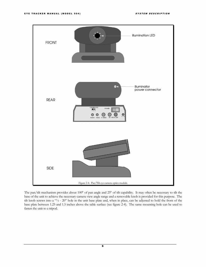
2.1 Major Assemblies2.1.1 Pan/Tilt eye camera optics moduleThe pan/tilt module is shown in figure 2-3. It normally rests on a horizontal surface (E.g. table top), but can also mountto a tripod. A ring of near infrared LED’s around the lens opening provides eye illumination. A main power switch, andall the necessary connectors are located on the base (non moving) platform rear panel, accept for the illuminator powerconnector which is located at the rear of the moving platform. A separate power supply connects to a DC power inputconnector on the rear panel and plugs into a standard AC wall outlet. An IR remote control unit provides manual controlfor pan/tilt positioning, lens focus and zoom, and various other features built into the pan/tilt camera. The eye cameravideo output is 60 Hz (NTSC) or 50 Hz (PAL) composite video format depending upon the video standard in thedestination country.
E Y E T R A C K E R M A N U A L ( M O D E L 5 0 4 ) S Y S T E M D E S C R I P T I O N
6
Figure 2-4. Pan/Tilt eye camera optics module.
The pan/tilt mechanism provides about 100° of pan angle and 25° of tilt capability. It may often be necessary to tilt thebase of the unit to achieve the necessary camera view angle range and a removable knob is provided for this purpose. Thetilt knob screws into a “¼ - 20” hole in the unit base plate and, when in place, can be adjusted to hold the front of thebase plate between 1.25 and 1.5 inches above the table surface (see figure 2-4). The same mounting hole can be used tofasten the unit to a tripod.

E Y E T R A C K E R M A N U A L ( M O D E L 5 0 4 ) S Y S T E M D E S C R I P T I O N
7
Figure 2-5. Pan/tilt module with tilt knob installed
The camera has an auto-focusing lens and a zoom function. As configured for eye tracking, the zoom setting actuallycontrols the range over which the camera can be focused. At maximum zoom magnification the camera will auto focusover a range of from about 18 to 24 inches. As zoom magnification is decreased, focus distances increase. The maximumdistance at which the eye tracker can be used effectively is about 40 inches from the camera to the eye.
The pan and tilt position, as well as some other pan/tilt module functions, can be manually adjusted from a hand heldremote control unit. The remote control is an IR emitting device and must be pointed towards the front of the pan/tiltmodule when used. Pan/tilt functions can also be controlled from the Eye Tracker Interface program described in section4.
2.1.2 Floor Mounted Scene Camera (FMSC) or Scan ConverterThe scene camera is used to produce a video image of the same scene the subject views. This video scene image providesthe reference frame for the eye point of gaze measurement. The color scene camera provided by ASL as part of thestandard model 504 system, is powered directly from the model 5000 control unit, is equipped with an 8 mm lens, andincludes a standard photography tripod to support the camera. The scene camera video output is 60 Hz (NTSC) or 50 Hz(PAL) composite video format depending upon the video standard in the destination country.
Alternately, if eye tracking subjects will be looking at a digital image, the system may include a scan converter in place ofthe scene camera. The scan converter converts the VGA computer screen image (being viewed by the subject) to acomposite video signal (either NTSC or PAL standard) which can be input to the eye tracker control unit as the scenevideo image. The scan converter is powered by its own external AC supply.

E Y E T R A C K E R M A N U A L ( M O D E L 5 0 4 ) S Y S T E M D E S C R I P T I O N
8
2.1.3 Model 5000 Eye Tracking System Control UnitThe Model 5000 Control Unit measures 3.25” h x 10.0” w x 10.25” d and weighs 4.5 lb., and includes an external 12VDCpower supply. The unit front panel (figure 2-5) contains a power switch and the rear panel (figure 2-6) contains allnecessary connectors. Basic use of the device requires the connectors labeled “Controller”, “Camera”, “Remote Scene”,“Eye Out”, “Scene Out”, and “12V DC IN”. These are the connections to the Interface PC; the eye camera, pan/tiltmechanism and illuminator; scene camera; eye monitor; scene monitor; and the DC power supply respectively. Otherconnectors support various options or secondary functions such as communications with a head tracker and data outputto an external device. The “HMO/PT” slide switch should be in the “P/T” position for use with pan/tilt optics.
The control unit houses the processing board that receives video from eye and scene cameras, recognizes features in thevideo eye image and computes line of gaze, communicates with the Interface PC, controls the pan/tilt mechanism, andsuperimposes feedback outlines, cross hairs, and cursors on the eye and scene video signals for monitor display. When anoptional magnetic head tracker is used, this processing board also communicates with the head tracker and can use the
Figure 2-6. Model 5000 Eye Tracker Control Unit front panel
Figure 2-7. Model 5000 Eye Tracker Control Unit rear panel
E Y E T R A C K E R M A N U A L ( M O D E L 5 0 4 ) S Y S T E M D E S C R I P T I O N
9
head position data to assist with control of the pan/tilt mechanism.
2.1.4 MonitorsThe standard system includes two video monitors, one for the eye image and a second for the scene image. If the scenemonitor is provided by ASL it may sometimes be equipped with a switch marked “normal/reverse”. This is primarily foruse with head mounted optics (model 501 eye tracker systems). If a monitor is equipped with this switch, keep the switchin the “normal” position for use with the model 504 system.
If monitors are supplied by the user, note that video cables must also be supplied. The monitor(s) may be black and whiteor color and must accept a standard EIA (black and white) or NTSC (color) composite video signal (CCIR or PAL if 50Hz cameras are being used).
The eye monitor displays the image from the eye camera. When the eye tracker is functioning properly, a white outline issuperimposed over the image recognized as the pupil and a black outline is superimposed on the image recognized as thecorneal reflection (CR). A white set of cross hairs designates the center of the pupil and a black set designates the CRcenter.
The scene monitor presents a video image of the scene being viewed by the subject, with a cursor or set of cross hairssuperimposed to indicate the subject’s point of gaze.
2.1.5 Eye Tracker Interface PC (Controller)A computer may be supplied by ASL as part of a series 5000 eye tracking system, but is usually supplied by the user. Thecomputer serves as the user interface device and as a data-recording device. ASL always supplies an Eye Tracker Interfaceprogram, which runs on this computer, and it is a required part of the system.
System requirements for the Interface PC are an IBM compatible PC capable of operation with Windows 95, Windows98, Windows NT, or DOS. Note, however, that a computer that can run only DOS is limited to using only the DOS version of ASL’sEye Tracker Interface Program. The computer must also have available COM1 or COM2 serial ports using standardinterrupts and device addresses. The minimum recommended system is a 200 MHz Pentium, but slower systems willprobably work adequately as well. In these cases consult ASL
2.1.6 SoftwareThe EYEPOS software package necessary to operate the eye tracker and record data is provided as a standard part of aseries 5000 Eye Tracker. The EYEPOS software is included on a CD ROM, labeled “EyeTracker Software”, or on afloppy disk labeled “EYEPOS”. Also included on the CD ROM or on a set of floppy disks is the EYENAL data analysissoftware, which includes a “CONVERT” function to convert binary data files to ASCII, and ACCESS software to allowaccess to binary data files from user written C programs.
2.2 Interface DescriptionThe Eye Tracker Interface PC is connected to the Model 5000 Control Unit with an serial RS232 cable from COM1 onthe PC to the “Controller” connector on the model 5000 control unit. If an optional magnetic head tracker is being usedit interfaces with a serial (RS232) connection to the Model 5000 Control Unit connector labeled “Head Tracker”. Realtime serial (RS232) data can be exported to an external device via the Model 5000 Control Unit connector labeled “SerialOut” (the interface protocol is described in section 6). The video images from either the scene or pupil monitor may alsobe video taped.

E Y E T R A C K E R M A N U A L ( M O D E L 5 0 4 ) S Y S T E M D E S C R I P T I O N
10
The port labeled XDAT on the Model 5000 Control Unit may be used to input parallel digital data from an externaldevice, for recording on the Eye Tracker Interface PC along with gaze data.
2.3 OptionsDescribed below are some additional components and software options, available from ASL, which may further enhancesystem operation.
2.3.1 Binocular and High Speed 504The model 504 is also available in High Speed (HS) option, capable of 60, 120, 240Hz. In addition there exists a remoteBinocular option consisting of two sets of optics to remotely track left and right eye movement.
2.3.2 Magnetic Head Tracking Hardware (MHT)The magnetic head tracking option (MHT) is a small unit that determines head position and orientation with goodaccuracy in six degrees of freedom. The head tracker output can be recorded independently of the eye tracker by a hostcomputer or by the Eye Tracker Interface PC. When used with the model 504 eye tracker system, the head tracker can beused by the Model 5000 Control Unit to assist in determining positions for the pan/tilt mechanism.
Head position is measured in six degrees of freedom at distances of up to 36 inches from the reference source (precisevalue depends upon model head tracker used). The unit consists of a control unit, a transmitter module (reference), and asmall sensor (or receiver) which is attached to a Velcro head band worn by the subject. Nylon screws are provided formounting the magnetic transmitter module. A cable is also provided to connect the MHT control unit to the “HeadTracker” port on the model 5000 Eye Tracker Control Unit.
The magnetic head tracker performance can be affected by large pieces of nearby metal or anything else that causesmagnetic field distortion. Consult ASL for details.

E Y E T R A C K E R M A N U A L ( M O D E L 5 0 4 ) I N T E R F A C E S O F T W A R E
11
3 INSTALLATION3.1 Unpacking and Assembly3.1.1 Control Unit Locate the model 5000 Eye Tracker Control Unit and unwrap the protective material. Be sure that the power switch onthe front panel is in the OFF (down) position.*For use with model 504 pan/tilt optics, be sure that the slide switch on the rear panel is in the “P/T” position*.
Locate the 12VDC power supply module and connect it to the “DC Power” connector on the Control Unit. Connect theother side to an AC power outlet. The power supply is input rated for 100 - 240 VDC, 50 or 60 Hz. The LED on theControl Unit front panel should remain off until the power switch is switched on.
3.1.2 Pan Tilt Optics The pan tilt module will be in a small box within one of the large shipping boxes. It is packed in protective foam alongwith a 13.5 VDC power supply, remote control, and the removable tilt knob. Place optics module on a flat surface or, if itwill be mounted to a tripod, fasten it to the tripod using the “1/4 - 20” hole under the nonmoving base. Be sure thepower switch is in the off position. Connect the 13.5 VDC supply to the “DC IN” connector.
3.1.3 Scene Camera If the scene camera (FMSC) was ordered from ASL, locate the scene camera in one of the shipping boxes. It will be a verysmall camera about 1in. sq (2.54cm sq). Locate the scene camera tripod and adjustable tripod head. The tripod will usuallybe in the manufacturer’s box within one of the two-foot cube boxes. Using the mounting screw on the tripod head,mount the scene camera on the tripod. The handle on the tripod head, which turns to loosen and tighten, may be used toposition the camera.
3.1.4 Scan ConverterIf a scan converter was ordered from ASL, find the Scan converter box, carefully unpack the components and place themnear the computer and monitor that is to provide the VGA display that the subject will look at. Note that use of the scanconverter is appropriate only if the eye tracker subjects will be looking at VGA computer display. There is no mechanicalassembly required, and cable connections are described in the “Interconnections” section (section 3.3.5).
3.1.5 Eye Tracker Interface PCIf the Eye Tracker Interface PC has been supplied by ASL, locate the computer, monitor, keyboard, and mouse, andassemble in the usual fashion. If supplied by ASL, the computer will have eye tracker software pre-installed. Softwareinstallation and operation procedures are discussed further on. It is assumed that the user is familiar with standard PCassembly and operation. If not, please consult ASL.
3.1.6 Magnetic Head Tracker (optional)The magnetic head tracker (MHT) unit comes individually packaged. The package contains a control box, a sourcemodule with cable and connector, a sensor module with cable and connector, and a manual with one or more floppydisks. The MHT system may be either an Ascension “Flock of Birds” or a Polhemus “FASTRAK” or “ISOTRAK” typesystem. Consult ASL for comparative details.
The MHT transmitter (source) module must be mounted to a stable, nonmetallic surface using the nylon screws provided.Placement of the transmitter is discussed in the following section.

E Y E T R A C K E R M A N U A L ( M O D E L 5 0 4 ) I N T E R F A C E S O F T W A R E
12
It is suggested that the transmitter be mounted so that it will be just above and behind the subject’s head; and so that whenthe subject’s head is in the nominal center (or average) position, the sensor will be about 10-12 inches from the source. Ifpossible the source should be oriented such that the x-axis is directed toward the subject and so that the y-axis pointsdown. It is also very important that the transmitter be rigidly supported, since any motion of the transmitter will introducean error in the data.
3.2 Component Placement3.2.1 Optics and SceneThe standard placement of the pan tilt module and resulting “measurable field of view” is shown in Figure 3-1. Themeasurable field of view is shown in another way by figure 3-2. Note that the measurable field extends symmetrically toeither side the pan/tilt camera and above the pan/tilt camera, but only a small distance below the camera. This is becausethe upper eyelid begins to occlude the camera’s view of the eye when the subject looks below the eye camera. For thisreason the pan/tilt camera module should ideally be placed near the bottom of, or below, the desired field of view, butnear the horizontal center of the desired field of view. Such an arrangement minimizes eyelid occlusion of the pupil andprovides left to right symmetry. It is possible; however, to put the optics unit at many different positions, and less thanideal positioning may sometimes be required for a particular application or experiment. Figures 3-3, 3-4, and 3-5 showtypical component placement when the subject will be viewing a computer monitor.
The optics unit may be placed anywhere so long as the following constraints are observed.
1. The optics unit to eye distance (D" in figure 3-1.) must be in the range of 18-40 inches. The recommendedoptics to eye distance is from the mid 20’s to low 30’s of inches.
2. There must be a clear optical path between the optics unit and the eye.

E Y E T R A C K E R M A N U A L ( M O D E L 5 0 4 ) I N T E R F A C E S O F T W A R E
13
3. Wherever the optics unit is placed, the measurable field of view will be about 25 degrees visual angle toeither side of the optics, about 25 degrees above the optics and about 10 degrees below the optics as shownin figures 3-1, and 3-2. The method for calculating visual angles is shown in figure 3-3.
Figure 3-1. Measurable field of view as seen from the top and side

E Y E T R A C K E R M A N U A L ( M O D E L 5 0 4 ) I N T E R F A C E S O F T W A R E
14
Figure 3-2. Measurable field of view shown from subject’s view point The field is approximate since precise boundaries will vary from subject to subject.
Figure 3-3 Computation of visual angle between points on a flat surface.

E Y E T R A C K E R M A N U A L ( M O D E L 5 0 4 ) I N T E R F A C E S O F T W A R E
15
Although the optics-to-eye distance is restricted as previously described, there is no such restriction on eye-to-scenedistance. The scene may be a video display, a slide projection, or any other display. It may be at any distance so long as itfalls within the visual field defined by figures 3-1 and 3-2. Errors in point of gaze measurement due to head motion will beminimized when the scene being viewed by the subject is at the same distance from the subject as the front of the pan/tiltmodule. Such optimal placement may not always be practical, however, and other arrangements do not precludesuccessful gaze measurement.
Figures 3-4 through 3-7 show some typical scene and pan/tilt module arrangements. In figures 3-4 through 3-6 the scenebeing viewed by the subject is a monitor. Note that only figure 3-4 satisfies the optimal conditions by placing the opticsmodule and scene surface the same distance from the subject, and placing the optics module just below the scene butcentered horizontally. Figure 3-5 shows the optics placed to one side of the monitor. This will work well so long as theupper right corner of the monitor remains within about 25 degrees visual angle from the optics module. (Measurementscould also be made when the subject looks to the left of the pan/tilt module, but in the case of figure 3-5 this is wastedcapability since there is nothing there for the subject to look at.) If the surface to be viewed by the subject is especiallylarge, like the very large monitor shown by figure 3-6, the optics module may have to be placed just in front of the surfaceas shown in figure 3-6. If the pan/tilt module were placed below this large monitor, points at the top of the monitorscreen would probably be more than 25 degrees visual angle from the pan/tilt optics, and the top of the monitor screenwould be beyond the measurable field. In other cases, such as a subject viewing a large projection screen, the pan/tilt
optics module may have to be even further from the scene surface as shown in figure 3-7.
Figure 3-4. Optimal placement for .the pan/tilt optics module and a monitor to be viewed by eye tracking subjects.The pan/tilt unit should be as close as possible to the bottom of the monitor screen.

E Y E T R A C K E R M A N U A L ( M O D E L 5 0 4 ) I N T E R F A C E S O F T W A R E
16
There must also be a method for displaying a nine-point target pattern on the display scene surface. This calibration targetdisplay is explained in more detail in section 5.1.
The scene camera should be placed so that it captures the scene of interest, i.e., the scene that the subject will be viewing.
Figure 3-5. Pan/tilt optics module placed beside monitor to be viewed by eye tracking subjects.Figure 3-6. Pan/tilt optics placed in front of a very large monitor.
Figure 3-7. Pan/tilt module mounted on tripod in front of projection screen.
E Y E T R A C K E R M A N U A L ( M O D E L 5 0 4 ) I N T E R F A C E S O F T W A R E
17
It should be placed as close to the subject’s head as possible so that the scene camera image shows the same perspective asthat seen by the subject. If scene video can be used directly or with the help of a scan converter, as described in section2.1.2, a scene camera is not required at all.
Although a tripod is provided for the scene camera the camera may also be mounted in any other way that is convenient.It is recommended that the scene camera be mounted securely enough so that its position will not often be changedaccidentally by someone bumping it or brushing against it. As will be seen in section 5, system calibration requires that thescene camera be stationary and certain procedures must be repeated if it moves.
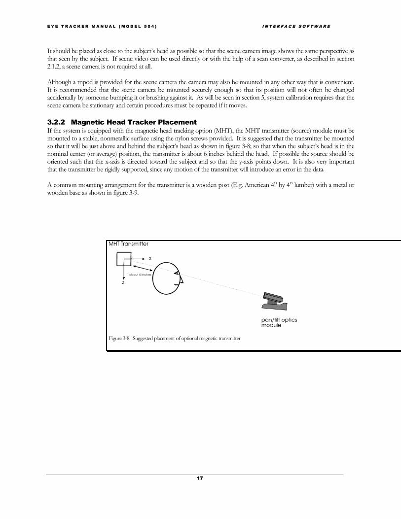
3.2.2 Magnetic Head Tracker PlacementIf the system is equipped with the magnetic head tracking option (MHT), the MHT transmitter (source) module must bemounted to a stable, nonmetallic surface using the nylon screws provided. It is suggested that the transmitter be mountedso that it will be just above and behind the subject’s head as shown in figure 3-8; so that when the subject’s head is in thenominal center (or average) position, the transmitter is about 6 inches behind the head. If possible the source should beoriented such that the x-axis is directed toward the subject and so that the y-axis points down. It is also very importantthat the transmitter be rigidly supported, since any motion of the transmitter will introduce an error in the data.
A common mounting arrangement for the transmitter is a wooden post (E.g. American 4” by 4” lumber) with a metal orwooden base as shown in figure 3-9.
Figure 3-8. Suggested placement of optional magnetic transmitter

E Y E T R A C K E R M A N U A L ( M O D E L 5 0 4 ) I N T E R F A C E S O F T W A R E
18
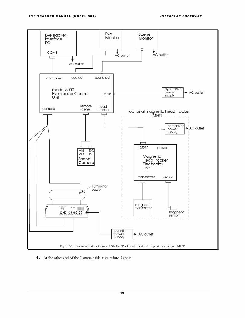
Figure 3-10 show interconnections for a standard model 504 Eye Tracker and optional magnetic head tracker.
3.3 InterconnectionsNOTE: for pictures of your system, components, and connections see the 504 Power Point (504.ppt) included onthe manuals CD.
3.3.1 Pan/Tilt Optics module Connections1. Be sure that system power and pan/tilt module power are OFF.
2. Connect the 13.5 VDC power supply to the pan/tilt module “DC IN” connector, and to an AC wall outlet.
3. Find the camera/control-unit cable (white/red dot). It has 25 pin D type connector at one end, andmultiple connectors at the other. The standard length is 7.6 meters (25 ft.) although other lengths areavailable (consult ASL).
4. Plug the 25 pin D type connector into the connector labeled “Camera” (white/red dot) on the model 5000Eye Tracker Control Unit. If there is a small cable with a BNC connection splitting of the at the 25 pinconnector, it should be connected to the A/B switch on the Scene monitor. (For more information seesection 3.3.2 Wide Angle locating Camera.)
Figure 3-9. Suggested mounting arrangement for magnetic transmitter.
E Y E T R A C K E R M A N U A L ( M O D E L 5 0 4 ) I N T E R F A C E S O F T W A R E
19
Figure 3-10. Interconnections for model 504 Eye Tracker with optional magnetic head tracker (MHT)
1. At the other end of the Camera cable it splits into 5 ends:
E Y E T R A C K E R M A N U A L ( M O D E L 5 0 4 ) I N T E R F A C E S O F T W A R E
A. connect the plug with the yellow end, into the socket labeled “VIDEO OUT” (yellow dot) on the rearpanel of the pan/tilt base
B. connect the yellow/blue end to the socket labeled “VISCA IN” with (yellow/blue dot) on the rearpanel of the pan/tilt base
C. Next connect the white/blue end with the other white/blue cable extending out from the neck of thepan/tilt.
D. Connect the green blue end to the small power supply with the came color code.
E. Plug the remaining socket into the connector on the rear of the moving head on the pan/tilt assembly(see figure 2-3 and the 504 power point tutorial).
2. Strain relieve the cable at the pan tilt end by taping it to the table or tripod leg, etc. Cable ties or other strainrelief techniques may also be used. Be sure that the illuminator cable (the lead that is connected to themoving part of the pan/tilt mechanism) has enough slack to accommodate full panning motion of themechanism. If the point where the cable separates into multiple leads is fixed close to the pan/tilt rearpanel, there will be sufficient slack.
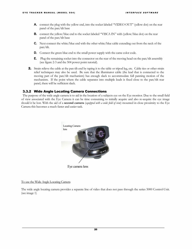
3.3.2 Wide Angle Locating Camera ConnectionsThe purpose of the wide angle camera is to aid in the location of a subjects eye on the Eye monitor. Due to the small field
of view associated with the Eye Camera it can be time consuming to initially acquire and also re-acquire the eye imageshould it be lost. With the aid of a second camera (equipped with a wide field of view) mounted in close proximity to the EyeCamera this becomes a much faster and easier task.
To use the Wide Angle Locating
The wide angle locating camera(see image 1)
Locating Camera
20
Camera
provides a separate line of video that does not pass through the series 5000 Control-Unit.
lens
Eye camera lens

E Y E T R A C K E R M A N U A L ( M O D E L 5 0 4 ) I N T E R F A C E S O F T W A R E
The Wide angle camera has two connections. One is for power and is indicated by a Green/blue color code. The second isvideo out, indicated by the Blue/White color code (see image 2).
Connecting the wide angle video out to a monitor
If using the two 9 inch monitors supplied by ASL, ASL will provide either an external “A-B” switch or amonitor with an internal A-B switch (see diagram 2). The A-B switch allows one to view the wide angle channel whennecessary. Alternately one could use a third monitor if available.
When using two monitors it is most advantageous to have access to both the locating camera view and that ofthe Eye Camera at the same time. Thus the A-B switch should be arranged with the A channel carrying the Scene image(Blue = color code) and the B channel carrying the wide angle locating camera image (Blue/white = color code) image 3.The A-B switch connects to the monitor (Blue/orange = color code) image 4.
image 1
Locating Camera Video
LocatingCamerapower
image 2
21
image 3
image 4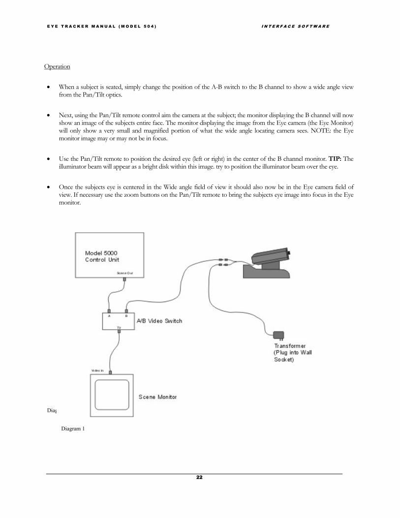
E Y E T R A C K E R M A N U A L ( M O D E L 5 0 4 ) I N T E R F A C E S O F T W A R E
22
Operation
• When a subject is seated, simply change the position of the A-B switch to the B channel to show a wide angle viewfrom the Pan/Tilt optics.
• Next, using the Pan/Tilt remote control aim the camera at the subject; the monitor displaying the B channel will nowshow an image of the subjects entire face. The monitor displaying the image from the Eye camera (the Eye Monitor)will only show a very small and magnified portion of what the wide angle locating camera sees. NOTE: the Eyemonitor image may or may not be in focus.
• Use the Pan/Tilt remote to position the desired eye (left or right) in the center of the B channel monitor. TIP: Theilluminator beam will appear as a bright disk within this image. try to position the illuminator beam over the eye.
• Once the subjects eye is centered in the Wide angle field of view it should also now be in the Eye camera field ofview. If necessary use the zoom buttons on the Pan/Tilt remote to bring the subjects eye image into focus in the Eyemonitor.
Diagram 2
Diagram 1
E Y E T R A C K E R M A N U A L ( M O D E L 5 0 4 ) I N T E R F A C E S O F T W A R E
23
3.3.3 Eye Tracker Interface PC ConnectionsUse the provided cable (RS232 cable with green dot) to connect the port labeled “Controller” on the model 5000 EyeTracker Control Unit to the COM1 port on the Interface PC. (NOTE: if it is necessary to use a different COM port please consultASL).
3.3.4 MonitorsConnect a video cable from the eye monitor video input (orange dot), to the control unit connector labeled “Eye Out”(orange dot). Connect a video cable from the scene monitor video input, (blue dot) to the control unit connector labeled“Scene Out” Blue (dot).
3.3.5 Magnetic Head Tracker Connection (Optional)The transmitter (source) and sensor modules attach to the clearly labeled connectors on the MHT electronics unit. See themanual packaged with the MHT system for details. Connect one end of the provided MHT interface cable (yellow/reddot) to the RS232 port on the MHT control unit marked with a yellow/red dot. Connect the other end of the MHTinterface cable to the model 5000 Eye Tracker Control Unit connector labeled “Head Tracker” marked also with ayellow/red dot. Set the DIP switches on the MHT electronics unit for 19200 Baud RS232 communications; all switchesset down except switch number 0ne which is up. (consult manufacturer’s manual packaged with the MHT system forproper DIP switch settings). The MHT system type must also be set in the interface program (e5win.exe). This should bedone before trying to establish communications between the control unit and the MHT. The system type can be setthrough the MHT pull down menu (see section 4.2.4).
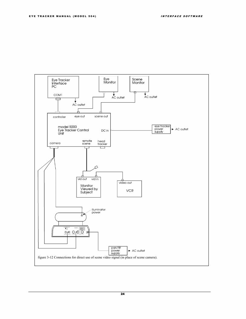
3.3.6 Direct Use of Scene VideoIf the subject will be viewing a video image (E.g., a videotape displayed on a monitor) the same video signal can be useddirectly as the scene video signal for the eye tracker, rather than using a separate scene camera. If the subject will beviewing a computer screen, a scan converter can be used to convert the computer image (E.g. VGA) into a compositevideo signal, which in turn can be used as the eye tracker scene video signal. Note that ASL can supply a scan converterinstead of, or in addition to a scene camera. Recommended connection for these configurations are shown in figures 3-11and 3-12 (also see figure 2-2).
E Y E T R A C K E R M A N U A L ( M O D E L 5 0 4 ) I N T E R F A C E S O F T W A R E
24
figure 3-12 Connections for direct use of scene video signal (in place of scene camera).

E Y E T R A C K E R M A N U A L ( M O D E L 5 0 4 ) I N T E R F A C E S O F T W A R E
25
Figure 3-11. Connections when using scan converter to supply scene video signal
E Y E T R A C K E R M A N U A L ( M O D E L 5 0 4 ) I N T E R F A C E S O F T W A R E
26
3.4 Software InstallationEye Tracker software is shipped on a CD. If the Eye Tracker Interface PC has been supplied by ASL, theappropriate software will already be installed on the hard drive.
If the computer was not supplied by ASL, locate the CD labeled “Eye Tracker Software” and follow thedirections on the label to install.
As previously discussed in section 2.1.5, system requirements are an IBM compatible PC capable of operation withWindows 95, Windows 98, or Windows NT, 2000, or XP if using the Windows eye tracker interface or DOS if using theDOS eye tracker interface. The computer must also have available COM1 or COM2 serial ports using standard interruptsand device addresses. The minimum recommended system is a 200 MHz Pentium, but slower systems will probably workadequately so long as they can effectively run Windows 95, 98, or NT. In any case, running other simultaneousapplications that take up a significant portion of the PC processor time may cause eye data to be lost. When not recordingdata the only consequence of the PC not having enough time will be a sluggish interface program display.

E Y E T R A C K E R M A N U A L ( M O D E L 5 0 4 ) I N T E R F A C E S O F T W A R E
27
4 EYE-TRACKER INTERFACE SOFTWAREThe EYEPOS (E5000) software package contains software that must be uploaded to the model 5000 eye tracker controlunit as well as a user interface program. The following sections assume that all appropriate interconnections have beenmade and software installed, as described in section 3. This manual also assumes that Windows interface program(e5Win) will be used. ASL can provide a manual upon request that describes system operation in terms of the DOSInterface program (e5000). .
4.1 Upload software to the model 5000 Eye Tracker Control UnitPower up the model 5000 Control Unit. If it is already powered up, use the power switch to power cycle it offand back on again to be sure that it is “reset”.
1) Open the Eye Tracker Interface program (e5Win) either by:
• clicking on the Start button → Programs → ASL Eye Tracking → Eye Tracker Interface
• double clicking a corresponding desktop shortcut
• using Windows Explorer to navigate to the “Eye Tracking” directory (usually under C:\ProgramFiles\ASL Eye Tracking) and double clicking e5Win.exe.
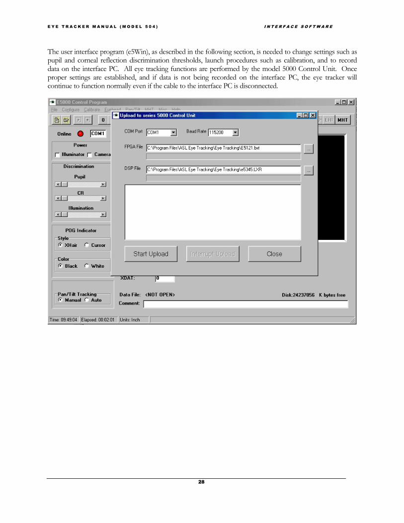
After several seconds, the interface program main screen will appear along with a pop up window called“Upload to Series 5000 Control Unit”. If necessary, use the COM Port menu box to specify the PC COM portactually being used (the default is COM1). If necessary, use the Baud Rate menu box to set the proper baudrate.
Note: ASL Series 5000 Control Units with serial # 1264 and higher have a baud rate of 115200Kbuad. ASL Series 5000 Control Units with serial # 1263 and lower have a baud rate of 57600Kbuad.
The FPGA and DSP file names should automatically by set to the proper files
2) Click “Start Upload”. Progress bars, on the Upload window, will show software being uploaded first to the fieldprogrammable gate array (FPGA), and then to the digital signal processor (DSP) in the control unit.After a successful upload the pop up window will disappear, leaving the interface program mainscreen. The green “On Line” light, at the upper left of the screen should be on.
If errors are encountered, the pop up will not close, and the scrolling display window will contain an errormessage with a suggestion for how to proceed.
Once the control unit has been “loaded” the on board software will continue to run until power is turned off.It is not possible to reload software to the control unit until the unit has been powered off and back on to“reset” the unit. If an attempt is made to reload the control unit without first resetting it (by clicking theUpload button on the interface, or selecting “upload to control unit” from the Configuration menu), a pop upmessage will prompt the user to first power cycle the control unit.
E Y E T R A C K E R M A N U A L ( M O D E L 5 0 4 ) I N T E R F A C E S O F T W A R E
28
The user interface program (e5Win), as described in the following section, is needed to change settings such aspupil and corneal reflection discrimination thresholds, launch procedures such as calibration, and to recorddata on the interface PC. All eye tracking functions are performed by the model 5000 Control Unit. Onceproper settings are established, and if data is not being recorded on the interface PC, the eye tracker willcontinue to function normally even if the cable to the interface PC is disconnected.

E Y E T R A C K E R M A N U A L ( M O D E L 5 0 4 ) I N T E R F A C E S O F T W A R E
29
4.2 E5000 User Interface ProgramOnce software has been successfully uploaded to the model 5000 eye tracker control unit (as described in the previoussection) close the DOS window. Next, run the interface program by double clicking the e5win.exe file in WindowsExplorer (EYEPOS directory), or by double clicking the corresponding shortcut icon on the desktop (assuming a shortcuticon was created as suggested in the Installation section). If the PC is correctly connected to a Model 5000 Control Unitand software has successfully been uploaded to the control unit (as described in the previous section) the “Online” light,near the top left of the interface program screen should be green.
Note that a DOS interface program e5000.exe can be used instead of e5win. Simply double click e5000.exe, in the EYEPOS directory,instead of e5Win.exe. A separate manual is available from ASL that describes system operation in terms of DOS Interface. This manualassumes that e5Win (windows version) is being used.
To exit (close) the interface program, click the “X” at the upper right of the program window or select “close” from thepull down “File” menu.
4.2.1 User Interface ScreenThe main interface program window has a menu bar at the top, a shortcut bar directly underneath the menu bar, a columnof controls extending down the left side of the screen, two graphics windows labeled “eye” and “scene POG” to the right

E Y E T R A C K E R M A N U A L ( M O D E L 5 0 4 ) I N T E R F A C E S O F T W A R E
30
of the control column, and some additional digital information displays below the graphics windows.
The controls consist of standard windows slide switches, check boxes, and radio buttons. The data displays consist ofindicator lights (to indicate “on-line” or “off-line”, and pupil and CR recognition), and text windows displaying COM portassignment, PC time of day, elapsed time, free disk space, point of gaze coordinates, pupil diameter, external data values(XDAT), and data file information. The “on-line” indicator light and COM port assignment displays are at the top of thecontrol column. The rest of the data displays are beneath the two graphics windows. If a magnetic head tracker isconnected and enabled, an additional data display appears beneath the Scene POG window showing head tracker positionand orientation coordinates.
The “eye” graphics display at the top, left side of the screen, shows pupil and corneal reflection (CR) center positions anddiameters, as detected by the eye tracker. The pink pupil center cross hairs and blue CR center cross hairs are essentiallythe same as the white and black cross hairs that show pupil and CR centers on the eye video monitor. The pupil and CRcircles are not the same as the pupil and CR outlines displayed on the video monitor. The computer display simply draws circles about the crosshair positions with diameters proportional to detected pupil and CR diameters. These circles do not show the actual pupil and CR outlinesdetected by the eye tracker. True outlines are displayed on the video eye monitor.
Another graphics window labeled “Scene POG” and located near the top right of the screen, shows a point of gazecursor. This is essentially the same as the cursor movement on the video scene monitor. Target points are also displayedin the “Scene POG” window.
If the Model 5000 Control Unit is not running (powered off or reset) or if the cable connecting the interface PC to thecontrol unit is disconnected, the light labeled “On line”, at the top left of the screen will turn red. If the communication isreestablished, for example by reconnecting the cable, this light will change back to green.
4.2.2 System SettingsPull down the Configure menu by clicking on “Configure” in the menu bar at the top left of the screen, and select“System Settings” to pop up the System Settings dialog window. Use the radio buttons in the box labeled “System Type”to select the system type that reflects the current hardware configuration. Set the eye camera speed to correspond to theupdate rate of the eye camera being used by clicking on the down arrow next to the corresponding camera speed box andselecting from the drop down list. (If the optional high-speed camera is being used, remember that the camera dipswitches must also be properly set for the selected update rate). The “speed” setting in the interface program SystemSettings window does not actually control the camera update rate; rather it informs the program of the type of eye camerabeing used.
Use the drop down list, in the System Settings window, to assign a COM port (usually either COM1 or COM2) as theinterface program port. Be sure that this assignment corresponds to the physical connection between the PC and the“Controller” port on the eye tracker control unit.

E Y E T R A C K E R M A N U A L ( M O D E L 5 0 4 ) I N T E R F A C E S O F T W A R E
31
Figure 4-1. System Settings Dialog Window
The eye position data output will be averaged over the number of fields specified by the item, labeled “Number of eyeposition fields to average”. Simply type in the desired number of fields. The recommended value for the pan/tilt opticssystem is 4. This means every eye position value computed will be averaged with the previous 3 values before beingdisplayed or recorded. To eliminate any averaging, enter 1 or 0. It is important to note that after a period during which apupil was not recognized (no valid gaze measurement could be made) the first valid measurement is not averaged. Thenext measurement is averaged with just the previous valid field, and the number of fields averaged increases in this wayuntil the specified value is reached.
The check boxes on the System Settings window should usually be left unchecked. The 17-point calibration capability isexplained in section 5.10 and the auto Eyedat function is explained in section 5.8. “Use Metric System” applies only tosetup of a magnetic head tracker for use with pan/tilt optics, as discussed in section 5.1.3. The other two check boxes donot apply to pan/tilt optics and should be left unchecked.
The “Scene Video Source” radio button should normally be left on “Auto Select” when using pan/tilt optics. When“System Type” is set to “Pan/Tilt Optics” or “Pan/Tilt Optics with MHT option” the system will automatically select the“Remote Scene” connector, on the control unit rear panel, as the scene video source. (When using Head mounted opticswith a head mounted scene camera, the scene video signal is usually part of the cable that connects to the “Camera”connector on the control unit).
Click “OK” to save system settings and close the System Settings dialog window.

E Y E T R A C K E R M A N U A L ( M O D E L 5 0 4 ) I N T E R F A C E S O F T W A R E
32
If software has been properly uploaded to the eye tracker control unit, and the COM ports have been properly assignedthe “Online” light, near the top left of the screen should be green to indicate that the PC is communicating with the eyetracker control unit. If this light is red, indicating lack of communication between the PC and eye tracker control unit,check connections and try re-uploading software to the control unit. (To upload, exit the interface program and followthe directions in section 4.1).
4.2.3 Saving and Retrieving Default Data (“Save As” & “Read”)The current subject calibration data and configuration settings are stored on the same directory as the E5Win program, infiles called E5000.CAL and E5000.CFG respectively. When a pan/tilt optics module is being used (model 504),information about the pan/tilt module settings and its position with respect to the optional magnetic head tracking system(MHT) is stored in a file called E5000.PTC.
These files are all automatically updated whenever changes are made to the data they contain, and are loaded whenever theE5000 program is loaded. For example, E5000.CAL is automatically updated at the completion of every subjectcalibration. Thus, the last calibration performed is remembered and reloaded the next time the E5000 program isexecuted. Similarly, the E5000.CFG file is updated whenever <OK> is clicked to exit from the “System Settings” dialogwindow.
To save one of these default files for future use, or to retrieve an old file previously saved, use the “Save As” or “Read”selections from the corresponding pull down menu. For E5000.CAL, use the “Calibrate” menu; for E5000.CFG, use the“Configuration” menu and for E5000.PTC, use the “Pan/Tilt” menu.
For example, to save a particular set of calibration data, use the “Save As” selection on the “Calibrate” menu. In responseto the prompt, enter a file name other than E5000.CAL, such as PETER.CAL, and click <Save>.
To use calibration data previously saved in this way, select “Read” from the “Calibrate” menu, browse to the previouslysaved file, highlight it and click <Open>. It will be used as the current data until overwritten by a new calibration.
If preferred, the same file manipulations can be done with Windows Explorer. Simply copy the E5000.xxx file to adifferent name to save it, and copy it back to E5000.xxx (in the same directory as the E5Win program) to re-use it.
4.2.4 Enabling Magnetic Head Tracker (Optional)The following section applies only if an optional magnetic head tracking (MHT) system has been connected as describedin sections 2.3.2 and 3.3.4.
The pull down MHT menu has the following choices:
The “Set boresight” command will be grayed (inactive) until the MHT system is enabled.

E Y E T R A C K E R M A N U A L ( M O D E L 5 0 4 ) I N T E R F A C E S O F T W A R E
33
Before attempting to enable the MHT system for the first time, choose “Select MHT system” and be sure the pop upwindow, labeled “MHT Type” shows the type of MHT hardware actually being used. If not, use the arrow button toactivate the drop down menu, and select the proper type. If unsure of the proper type, consult ASL.
Use the “Enable “ selection to start communication between the MHT system and the eye tracker computer. Alternately,click the MHT button at the far right side of the shortcut bar. If communication is successful the MHT data display,labeled “MHT/ Transmitter Offset” should appear under the “Scene POG” display window( fig. 4-3).
The “Enable” menu selection as well as the MHT short cut button are toggle switches, so once the MHT system isenabled, the top item on the MHT menu reads “Disable” and the MHT shortcut button appears activated (presseddown). The “Disable” selection or clicking the activated MHT button will disable MHT communication and the MHTdata display will disappear.

E Y E T R A C K E R M A N U A L ( M O D E L 5 0 4 ) I N T E R F A C E S O F T W A R E
34
Figure 4-2. Main window with MHT enabled. Notice “Raw MHT” display near lower right.
The MHT data display consists of 3 position and 3 orientation values. The position values are the position of themagnetic sensor with respect to the transmitter x, y, and z axes. The orientation values are the azimuth (“az”), elevation(“el”), and roll (“rl”) angles (often called Euler angles) that describe the orientation of the sensor axes with respect to thetransmitter axes. Position values are expressed in inches, and orientation values are expressed in degrees.
If the MHT system is communicating properly with the eye tracker computer, the MHT display values should changewhen the sensor moves, and should match the actual position of the sensor with respect to the transmitter. Actually, thevalues will probably be constantly changing, even when the sensor is stationary, due to noise in the system.
The “Set Boresight” command (under the MHT menu) will cause the sensor coordinate frame to rotate, so that sensororientation angles are zero for the current sensor orientation. When MHT mirror tracking (as is the case with the model504), boresights are done automatically at appropriate times, so this command need never be used during normal systemoperation. It may sometimes be useful, however, for checking to see that the MHT system is functioning properly.

E Y E T R A C K E R M A N U A L ( M O D E L 5 0 4 ) I N T E R F A C E S O F T W A R E
35
Some additional explanation of “boresight” may be helpful. The origin of the sensor coordinate frame is in the center ofthe sensor. Upon power up, or after a reset, the sensor coordinate frame x axis extends away from the sensor cable, andthe z-axis extends down from the sensor mounting surface. If looking in the positive x direction with the z-axis pointingdown, the sensor y-axis extends to the right. The MHT system reports the orientation of the sensor coordinate framewith respect to the transmitter coordinate frame. In other words, if the sensor is held so that sensor axes are aligned withtransmitter axes, the MHT system will report zero orientation angles.
If the sensor is held still in any orientation, and the boresight command is issued, the sensor axes will be rotated to alignwith transmitter axes. The sensor coordinate frame will maintain this new orientation, with respect to the physical sensor,until a reset is issued or until the unit is power cycled.
The third choice, “Reset MHT”, sends the same MHT initialization command string that is automatically sent during theMHT enable operation. The affect of any previous boresight (discussed above) will be canceled.

E Y E T R A C K E R M A N U A L ( M O D E L 5 0 4 ) S E R I A L & A N A L O G O U T P U T
36
5 EYE TRACKER OPERATIONThe following steps are necessary in order to successfully operate the eye tracker in the standard fashion
1. The model 5000 eye tracker control unit must be powered up and loaded with software from the InterfacePC, and the E5Win user interface program must be started. If an optional magnetic head tracker is beingused it must also be activated.
2. A calibration target point pattern must be entered using the E5Win user interface program (if appropriatevalues are not already stored on the default calibration file).
3. The pan/tilt camera must be properly aimed at the subject and zoom must be adjusted to accommodate theproper focus range. (Capture subject eye image)
4. The illuminator intensity and pupil and CR discriminators must be properly set using the E5Win userinterface program.
5. A subject calibration procedure must be executed.
6. Eye movement monitoring: the test, experiment, or mission may be performed.
Step one was described in the previous chapter (section 4). The following sections provide a detailed description of theremaining steps as well as descriptions of some special features.
There are some additional procedures needed in order to use the optional magnetic head tracker to assist pan/tilt operationand these are described in sections 5.1.3 and 5.2.3.
5.1 Setting Up Calibration Target Points5.1.1 OverviewDuring the calibration procedure it will be necessary for the subject to look at nine target points that are at known positions.If a scene camera (or other composite video source) is being used, the actual distribution of the nine points are usually takenfrom the scene monitor image, and entered into memory with the eye tracker “set target points” function. If a scenecamera is not being used, then the “set target points” routine must be used to enter a pattern of points that have the samerelative positions as the points being viewed by the subject.
If the stimulus scene is a video monitor, the target pattern can also be a video display on the same monitor. If the display isa projected slide, the calibration target can also be on a slide. If the scene is an instrument panel, the calibration targetpattern can be created by positioning small pieces of tape in appropriate places on the panel. Other methods are alsopossible.
If a scene camera is being used, be sure that the scene camera is properly positioned to view the scene; this can be judgedby observing the nine calibration target points on the scene monitor. It is necessary that the positional relationship betweenthe scene camera and the scene be maintained constant in order that the calibration remain valid. The scene camera shouldbe, therefore, stable and fixed.
E Y E T R A C K E R M A N U A L ( M O D E L 5 0 4 ) S E R I A L & A N A L O G O U T P U T
37
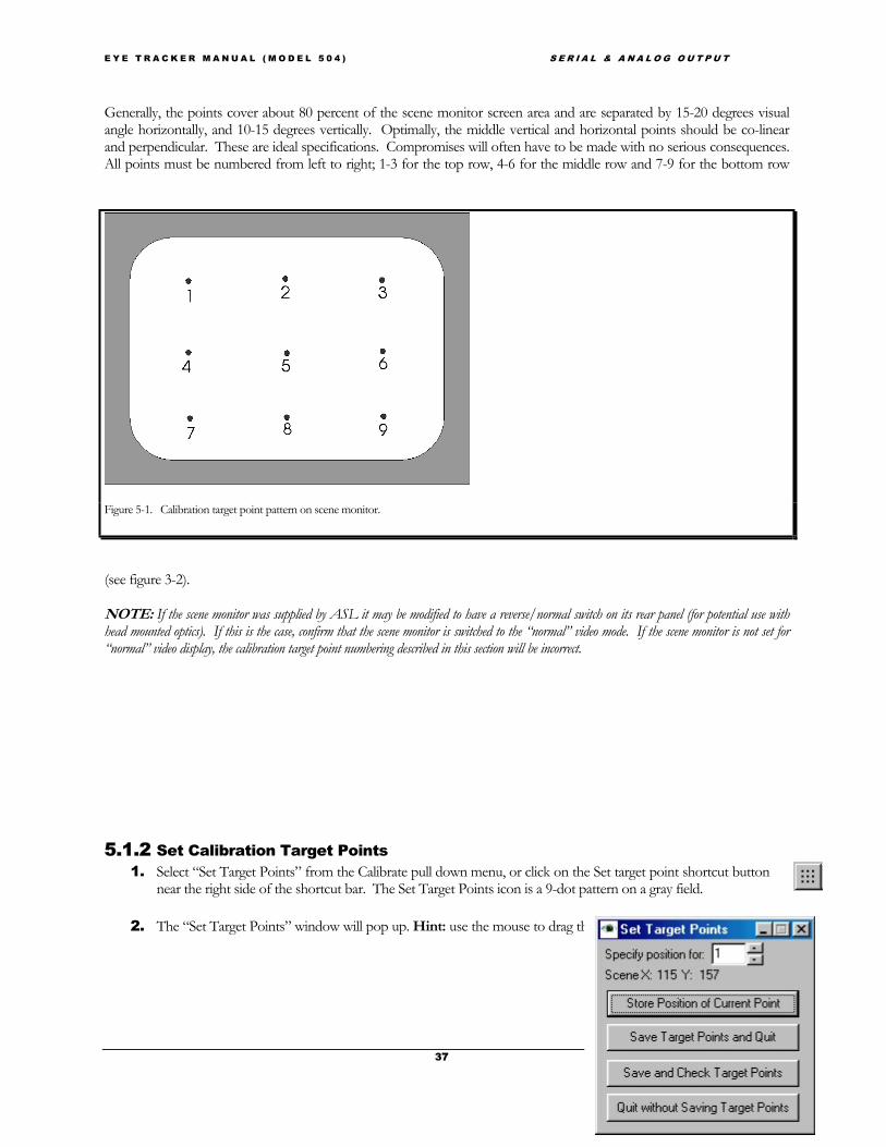
Generally, the points cover about 80 percent of the scene monitor screen area and are separated by 15-20 degrees visualangle horizontally, and 10-15 degrees vertically. Optimally, the middle vertical and horizontal points should be co-linearand perpendicular. These are ideal specifications. Compromises will often have to be made with no serious consequences.All points must be numbered from left to right; 1-3 for the top row, 4-6 for the middle row and 7-9 for the bottom row
(see figure 3-2).
NOTE: If the scene monitor was supplied by ASL it may be modified to have a reverse/normal switch on its rear panel (for potential use withhead mounted optics). If this is the case, confirm that the scene monitor is switched to the “normal” video mode. If the scene monitor is not set for“normal” video display, the calibration target point numbering described in this section will be incorrect.
5.1.2 Set Calibration Target Points1. Select “Set Target Points” from the Calibrate pull down menu, or click on the Set target point shortcut button
near the right side of the shortcut bar. The Set Target Points icon is a 9-dot pattern on a gray field.
2. The “Set Target Points” window will pop up. Hint: use the mouse to drag the “Set Target Points” window to
Figure 5-1. Calibration target point pattern on scene monitor.

E Y E T R A C K E R M A N U A L ( M O D E L 5 0 4 ) S E R I A L & A N A L O G O U T P U T
38
a more convenient position on the screen. Be sure not to cover any of the “Scene POG” window on the Interfaceprogram.
3. Once the “Set Target Points” window is displayed when ever the mouse cursor enters the “Scene POG” windowon the Interface program, it changes to a cross and its position coordinates with respect to the Scene Display areshown as “Scene X: nnn Y: nnn” on the Set Target Points Window. In addition, when the mouse is movedwithin the Scene POG window, a cursor on the video scene monitor is also displayed in the correspondingposition.
4. If a scene video image is available
• The video scene monitor displays the scene image whether it is a digital image captured through a scan converter orfrom a scene camera. The nine-point calibration display should be displayed on the video scene monitor during thisprocedure.
• Move the mouse (within the “Scene POG” area on the computer screen) to position the cursor on the video scenemonitor over point 1, and left click to enter point 1.
• Similarly left click on points 2-9, in sequence, to enter the other points. If preferred, use the up or down arrow keysto highlight the “Store Position of Current Point” button on the Set Target Point window, and use the <Enter> keyinstead of the left mouse button to enter the position of a given point.
• NOTE: The interface “Scene POG” window will display nine default points. The position of these points will beoverwritten as new target point positions are entered. If the default points remain visible after entering points 1-9,repaint the desktop by selecting the “Misc” pull down menu and choose Repaint Desktop.
5. If a scene video image is not available
• Use the position of the Scene Display cursor on the interface program screen, or the coordinate values on the SetTarget Point window to determine the target point positions. To enter target points out of order, click the small up ordown arrow buttons, at the right of the “specify position for:” indicator, to set the desired point.
6. Once all target points have been entered click “Save target points and Check” to save the points and bring up the“Check Target Points” window (see next section), or the “Save target points and Quit” button to save the pointsand close the Set Target Points window.
5.1.3 Check Calibration Target PointsPop up the “Check Target Point” dialog window by selecting “Check Target Points” from the Calibrate menu, or by
clicking the Check Target Points icon on the shortcut bar (9-point pattern with red check mark)
Use the up and down arrows next to the “Current Point:”indicator to select the desired point number. The indicatedpoint will be displayed on both the interface program ScenePOG window and the video scene monitor. Only theindicated “Current Point” will appear on the video scenemonitor.
5.1.4 MHT Pan/Tilt Tracking Calibration

E Y E T R A C K E R M A N U A L ( M O D E L 5 0 4 ) S E R I A L & A N A L O G O U T P U T
39
(MHT option only)OVERVIEW: If a system is equipped with the magnetic head tracker (MHT) option, the magnetic head tracker can beused to assist pan/tilt tracking. Normally, the pan/tilt mechanism is driven in response to motion of the eye image on theeye monitor. When the image moves towards one side of the eye camera field of view, the system drives the mirror in anappropriate direction to re-center the image
Optical tracking will not work once the eye image is lost from the eye camera field of view (for example, due to a very fasthead motion). A system equipped with the MHT option can use information about head position to find the eye evenwhen “lost” by the eye camera.NOTE: see the associated power point file (504.ppt) included in the ASL Manual CD or download at ftp://a-s-l.com/pub/504&mhtcalibration/.
In order for MHT assisted tracking to function properly, the computer must know where the pan/tilt optics are withrespect to the magnetic transmitter (source). Furthermore, it must know the relationship between MHT coordinate space(defined by the orientation of the magnetic transmitter), and pan/tilt coordinate space (defined by the mechanism pan andtilt angles). A calibration procedure must be performed to provide the computer this information. The MHT calibrationprocedure need be performed only once for a given magnetic transmitter and pan/tilt module placement. If eithercomponent is moved, the calibration must be redone. The MHT calibration is divided into two procedures: the “MHTTransmitter/Pan Tilt calibration” and the “Sensor to Pan Tilt Calibration”.
The following description assumes that the transmitter has been mounted and that the MHT electronicsunit along with all other components have been connected as described in section 3 of the model 504manual. Before proceeding, be sure that the MHT system is “Enabled” and is communicating properlywith the Eye Tracker computer as described in section .3.3. If not already powered up, switch on thepower switch at the rear of the pan/tilt module. When first powered up, the unit will turn all the way inone direction and will then return to a center position. The unit will powers up in the auto focus mode,and should be left in that mode. Be sure “illuminator” check box in the Interface is checked (to turn theilluminator on), and move the “illumination” slide switch to at least midway. Move the Pupil and CRDiscrimination slide switches all the way to the left. Be sure that Pan/tilt Tracking radio button (nearbottom left of the Interface screen) is set to manual and that the “System type” radio button on the“System settings” dialog window (under the Configure menu) is set to “Pan/Tilt optics with MHToption”. The MHT calibration procedure will probably require two people, one person to work thekeyboard and another to hold the magnetic sensor in various positions.
5.1.4.2 MHT Transmitter /Pan Tilt CalibrationSTEP 1 (see also the Power Point tutorial 504.ppt on the manuals CD or download at ftp://a-s-
l.com/ (contact ASL for username and password)Aiming the Pan/Tilt camera at the Transmitter
A) Pull down the “Pan/Tilt” menu and select “Setup”. To start out with, the “Zoom”, “Gain”, and “Iris”slide switches should be all the way to “Max”; and the “Shutter” slide switch should be at “Long”. The slideswitches can be moved by dragging them with the mouse, by clicking the right or left arrows on either end of theslide, or by clicking in the slide channel on either side of the current slide switch position.
B) Use the Wide Angle Locating Camera to assist the camera to gain focus on the transmitter (see section3.3.2). OR hold a finger, pencil, or some other object in front of the camera about 18-20 inches from the camera
5.1.4.1.1 GETTING STARTED:

E Y E T R A C K E R M A N U A L ( M O D E L 5 0 4 ) S E R I A L & A N A L O G O U T P U T
40
lens. The system should be able to focus on the object at this distance. Slowly move the object back away fromthe camera towards the magnetic transmitter. Once it gets to more than about 22 inches from the camera, thecamera will probably no longer be able to focus well. Move the “Zoom:” slide to the left until focus is restored.The zoom slide will not need to be moved far and it is probably best to move it by clicking the left arrow, at theleft side of the slide, rather than by dragging the slider with the mouse. In this fashion try to achieve focus whenthe object is at about the same distance from the camera as the magnetic transmitter.
C) Use the remote control to aim the pan tilt at the magnetic transmitter. Imagine a line from the pan/tiltlens to the center of the very center of the transmitter block. Notice that this imaginary line would intersect thefront face of the transmitter a bit below the center of that surface (see figure 3-8 pg.18). It is approximately thispoint that should be centered in the eye monitor.
STEP 2 Pull down the Pan/Tilt menu and select “MHT Pan/Tilt calibration”.
(Note that this selection will be grayed out if the MHT system is not enabled) A pop-up dialog box will appear asking “MHT Transmitter/Pan Tilt Calibration?”.
click “Yes”
STEP 3 Enter distance from pan tilt to MHT transmitter.
A) Use a tape measure to measure the distance from the optics module center of rotation to the center of themagnetic transmitter. The center of rotation is about 2 inches (5.1 cm) behind the plate that holds theilluminator LEDs (see figure 5.2), so a measurement can be made from this front plate, next to the lensopening, and then 2.5 inches can be added. (If the pan/tilt is not already aimed at the MHT transmitter, aim thepan/tilt as described in the previous section.)

E Y E T R A C K E R M A N U A L ( M O D E L 5 0 4 ) S E R I A L & A N A L O G O U T P U T
41
Figure 5-2. Distance from center of transmitter to pan/tilt center of rotation.
NOTE: the desired value is really the distance to the center of the transmitter, but of course the tape measure can only beheld against an outer face of the transmitter. Estimate the distance to the center as closely as possible by holding the tapemeasure along side the transmitter, or by separately measuring to the front surface of the transmitter and then, along theside of the transmitter, from the front surface to the approximate center.
B) Enter the appropriate value in the dialog box. THE VALUE MUST BE ENTERED IN UNITS OF INCHES, unless the “Usemetric system” check box has been selected in the “System settings” dialog window. If “Use metric system” has been checked,THE VALUE MUST BE ENTERED IN UNITS OF CENTIMETERS. (See section 4.2.2 for instructions on using the Systemsettings dialog window). If the value being displayed in the dialog box is correct, no change is necessary. Click “OK”. Note:selection of “Cancel” will simply not change the currently stored value (no matter what value is displayed in the dialog box).
STEP 4 Place sensor in-between pan tilt and transmitter
A new dialog box will appear with the message “Place sensor between pan tilt and transmitter”. With thetransmitter still centered in the eye monitor hold the small magnetic sensor so that it appears in the center of theeye monitor. Note that the orientation of the sensor does not matter, only its position in space matters. Hold thesensor so that one of its faces is directed toward the pan/tilt unit and appears centered in the eye monitor. Be
sure the sensor is no more than about 18 inches from the transmitter, roughly in the middle of the Pan tilt camera
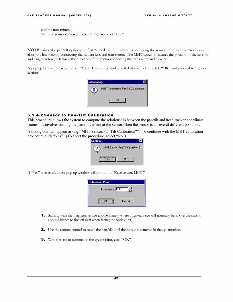
E Y E T R A C K E R M A N U A L ( M O D E L 5 0 4 ) S E R I A L & A N A L O G O U T P U T
42
and the transmitter.With the sensor centered in the eye monitor, click “OK”.
NOTE: since the pan/tilt optics were first “aimed” at the transmitter, centering the sensor in the eye monitor places italong the line (vector) connecting the camera lens and transmitter. The MHT system measures the position of the sensor,and can, therefore, determine the direction of the vector connecting the transmitter and camera.
A pop up box will then announce “MHT Transmitter -to-Pan-Tilt Cal complete”. Click “OK” and proceed to the nextsection.
5.1.4.2 Sensor to Pan-Tilt CalibrationThis procedure allows the system to compute the relationship between the pan/tilt and head tracker coordinateframes. It involves aiming the pan/tilt camera at the sensor when the sensor is at several different positions.
A dialog box will appear asking “MHT Sensor/Pan Tilt Calibration?”. To continue with the MHT calibrationprocedure click “Yes”. (To abort the procedure, select “No”)
If “Yes” is selected, a new pop up window will prompt to “Place sensor. LEFT”.
1. Starting with the magnetic sensor approximately where a subjects eye will normally be, move the sensorabout 6 inches to the left (left when facing the optics unit).
2. Use the remote control to move the pan/tilt until the sensor is centered in the eye monitor.
3. With the sensor centered in the eye monitor, click “OK”.
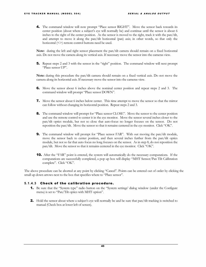
E Y E T R A C K E R M A N U A L ( M O D E L 5 0 4 ) S E R I A L & A N A L O G O U T P U T
43
4. The command window will now prompt “Place sensor RIGHT”. Move the sensor back towards itscenter position (about where a subject’s eye will normally be) and continue until the sensor is about 6inches to the right of the center position. As the sensor is moved to the right, track it with the pan/tilt,and attempt to move it along the pan/tilt horizontal (pan) axis; in other words, so that only thehorizontal (<>) remote control buttons need be used.
Note: during the left and right sensor placement the pan/tilt camera should remain on a fixed horizontalaxis. Do not move the camera along its vertical axis. If necessary move the sensor into the cameras view.
5. Repeat steps 2 and 3 with the sensor in the “right” position. The command window will next prompt“Place sensor UP”.
Note: during this procedure the pan/tilt camera should remain on a fixed vertical axis. Do not move thecamera along its horizontal axis. If necessary move the sensor into the cameras view.
6. Move the sensor about 6 inches above the nominal center position and repeat steps 2 and 3. Thecommand window will prompt “Place sensor DOWN”.
7. Move the sensor about 6 inches below center. This time attempt to move the sensor so that the mirrorcan follow without changing its horizontal position. Repeat steps 2 and 3.
8. The command window will prompt for “Place sensor CLOSE”. Move the sensor to the center positionand use the remote control to center it in the eye monitor. Move the sensor several inches closer to thepan/tilt optics module, but not so close that auto-focus no longer focuses on the sensor. Do notreposition the pan/tilt. Move the sensor so that it remains centered in the eye monitor. Click “OK”.
9. The command window will prompt for “Place sensor FAR”. With out moving the pan/tilt module,move the sensor back to center position, and then several inches further from the pan/tilt opticsmodule, but not so far that auto focus no long focuses on the sensor. As in step 8, do not reposition thepan/tilt. Move the sensor so that it remains centered in the eye monitor. Click “OK”.
10. After the “FAR” point is entered, the system will automatically do the necessary computations. If thecomputations are successfully completed, a pop up box will display “MHT Sensor/Pan Tilt Calibrationcomplete”. Click “OK”.
The above procedure can be aborted at any point by clicking “Cancel”. Points can be entered out of order by clicking thesmall up down arrows next to the box that specifies where to “Place sensor”.
5.1.4.3 Check of the calibration procedure.1. Be sure that the “System type” radio button on the “System settings’ dialog window (under the Configure
menu) is set to “Pan/Tilt optics with MHT option”.
2. Hold the sensor about where a subject’s eye will normally be and be sure that pan/tilt tracking is switched tomanual (Check box at lower left of screen).

E Y E T R A C K E R M A N U A L ( M O D E L 5 0 4 ) S E R I A L & A N A L O G O U T P U T
44
3. Turn pupil and CR discriminators OFF (slide switches all the way to the left), and use the pan/tilt remotecontrol to center the sensor in the eye monitor.
4. With the sensor centered in the eye monitor, pull down the Pan/Tilt menu and select “MHT SensorCalibration” or click the short cut button (the icon is a drawing of 3 dimensional coordinate axes, next to
button labeled SCC, near center of shortcut bar).
A pop up box will display “MHT Sensor Calibration Complete”. Click “OK”. Note that the sensor should becentered in the eye monitor when the shortcut button or the menu item is clicked (not when “OK” is clicked in response to the
“….Complete” message).
5. Set the pan/tilt tracking radio button to “Auto”.
6. Move the sensor to different positions within the motion box used during the MHT calibration procedure.The pan tilt should automatically re-aim itself at the sensor each time the sensor is moved. Don’t expect thesystem to exactly center the sensor image in the eye monitor when doing this test, if it brings the sensorimage to anywhere in the eye camera field of view (even at the very edge of the monitor) the calibration canbe considered successful.
7. If not successful, repeat the steps in section 5.1.3.3. If still not successful, repeat the procedure in section5.1.3.2 as well as the procedure in this section.
MHT calibration results are stored in the E5000.ptc file. If a very good calibration is achieved for a particular set up, it canbe copied to a different file name for safe keeping. If the E5000.ptc file is then accidentally changed or destroyed, thearchived copy can be copied back as E5000.ptc.
5.2 Subject Set-Up and CalibrationSubject set-up consists of seating the subject in an appropriate position, obtaining a suitable eye imageon the eye monitor, and setting the pupil and CR discriminators properly.
5.2.1 Subject SeatingAny stationary chair can be used, but to the extent that the type of chair can minimize subject motion,eye-tracking accuracy will be maximized. In addition a chair with adjustable seat height may bepreferable.
5.2.2 Obtaining an Eye ImageNote: This section and the next section on pupil and CR discrimination require the operator to Check the“Illuminator” check box on the Interface screen to turn on the illuminator by moving the slider labeled “illuminator”to the right. Be sure the “Pan/Tilt Tracking” radio button, near the bottom left of the Interface screen, is set tomanual and that the switch on the control unit rear panel is in the “P/T” position.
1. Pull down the “Pan/Tilt” menu and select “Setup”.The “Zoom”, “Gain”, and “Iris” slide switches should beall the way to Max; and the “Shutter” slide switch should beat Long. These are the default positions for these slide

E Y E T R A C K E R M A N U A L ( M O D E L 5 0 4 ) S E R I A L & A N A L O G O U T P U T
45
switches and it is best to have them set to default when first attempting to acquire a subject’s eye image. Useof these adjustments will be discussed in following sections.
2. FOCUS: Use the Wide Angle Locating Camera to assist in gaining focus or the followinginstructions. Hold a finger, pencil, or some other object in front of the camera about 18-20 inches from thecamera lens. The system should be able to focus on the object at this distance. If the subject’s eye is at agreater distance, slowly move the object back away from the camera. Once it gets to more than about 22inches from the camera, the camera will probably no longer be able to focus well. Move the “Zoom:” slideto the left until focus is restored. The zoom slide will not need to be moved far and it is probably best tomove it by clicking the left arrow. In this fashion try to achieve focus when the object is at about the samedistance from the camera as the expected distance of the subject’s eye.
3. SEAT SUBJECT: Have a subject sit down in front of the system, or position the model eye targetbar (black plate with white 4mm spot and ball bearing) so that the white spot is about where a subject’seye will be.
Hint: The model eye is useful for practicing set up and discrimination of the pupil and corneal reflection (CR) withoutrequiring a cooperative subject.
4. AIM THE CAMERA: Use either the infra red remote control or the arrows on the Pan/Tilt,Setup window to aim the pan/tilt camera at the eye (or model eye). If the “Reverse left/right” and“Reverse up/down” boxes near the bottom right of the Pan/Tilt Setup window are not checked,clicking an arrow moves the eye monitor image in the direction of the arrow. If the “Reverse” boxes arechecked then the pan/tilt camera will move in the direction of the arrow and the image (in the eyemonitor) will appear to move in the opposite direction (as thought the “window” through which theimage is being viewed were moving in the direction of the arrow). The inner ring of arrows move themodule a short distance for each click, while the outer arrows move the module a greater distance foreach click. TIP: see section 3.3.2 on the Wide Angle Location Camera
5. MHT OPTION: If not using a magnetic head tracker proceed to step 6. If your system has theMHT option, have the subject put on the provided headband and attach the magnetic sensor (themounting surface of the sensor and the head band are equipped with mating Velcro) so that the sensor islocated just above the eye being monitored. Be sure that the magnetic head tracker is enabled (asdescribed in section 4.2.4), that the system type radio button (System settings dialog window, under theConfigure menu) is set to “Pan/Tilt Optics with MHT option”.Complete the Sensor-to-Eye Vector procedure described in section 5.2.3. before continuing .
6. SET HOME: Once the pan/tilt module is aimed at the eye or (or at the model eye) pull down thePan/Tilt menu and select “Set Home”. This will cause the program to memorize the current position of thepan/tilt module. Subsequently selecting “Home” from the Pan/Tilt menu will cause the module to return tothis memorized position. The Home position can be helpful for reaquiring the subject’s eye when thesystem is not configured with the MHT option.Note: the “home” button on the Pan/Tilt remote does not correspond to the Home settings in the Interfacemenu.

E Y E T R A C K E R M A N U A L ( M O D E L 5 0 4 ) S E R I A L & A N A L O G O U T P U T
46
7. You should now see an image of the subject’s eye in the “Eye Monitor”.Proceed to the section 5.2.4
5.2.3 MHT sensor to eye calibration (MHT option only)The “Sensor to eye” calibration allows the system to compute the vector connecting the magnetic sensor and the eye.Remember that every time the headband and sensor are put on, the sensor will wind up in a slightly different position withrespect to the eye; this procedure must be done for each new subject. Do not proceed if the MHT to Pan/Tilt Cal hasnot been completed as described in section 5.1.4.
1. While the subjects eye image is centered in the Eye monitor or video window press the Sensor-to-Eye vector
button .A pop up box will display “MHT Sensor Calibration Complete” and the system will also automatically switchto “Auto” Pan/Tilt Tracking.Click “OK”.NOTE: this procedure does not require that Pupil and CR recognition be established.
The camera should now be able to automatically reacquire the subject’s eye in the presence of head movement.
If not using a magnetic head tracker, leave Pan/tilt tracking set to manual until proper pupil discrimination is achieved asdescribed in section 5.2.4.
SENSOR PLACEMENT:Figure 5-3 shows the standard position for the sensor while on the subject. It is possible to place the sensoranywhere on the subject’s head that is deemed convenient by using the “Sensor to Eye Offset”.
Figure5-3. standard position for MHT sensor.

E Y E T R A C K E R M A N U A L ( M O D E L 5 0 4 ) S E R I A L & A N A L O G O U T P U T
47
5.2.3.1 MHT SENSOR -TO-EYE OFFSET:
1. Measure the distance from the plane of the subject’s eye to the sensor.
2. Enter the distance in the Pan Tilt “Setup” menu, the first selection under the PanTilt pull down.
Have the subject hold as still as possible, andwith the subject’s eye image centered in the eyemonitor click “MHT Sensor Calibration” underthe “Pan/Tilt” menu, or click the shortcutbutton (the icon is a drawing of 3 coordinate
axes)
A pop up box will display “MHT SensorCalibration Complete” and the system will alsoautomatically switch to “Auto” Pan/TiltTracking.Click “OK”.
NOTE: that the eye image should be centeredin the eye monitor when the shortcut button orthe menu item is clicked (not when “OK” isclicked in response to the “. Sensor CalibrationComplete” message.
5.2.4 Pupil and CR DiscriminationThe first stage in recognition of the pupil and CR by the eye tracker is performed by edge detection logic. Threshold levelsfor pupil and CR edge detection are adjusted with the slide switches labeled “Pupil” and “CR”, under the “Discrimination”label heading. Also the Up/Down arrows adjust the Pupil slide bar and Left/Right arrows adjust the CR slide bar. Thecurrent discriminator levels are shown by the slide switch positions, with the far-left slide switch positions indicating that noedges will be noticed, and positions at the right of the slides indicating even dim edges may be detected.
Proper pupil and CR discrimination as seen on the video eye monitor (not the computer screen) is shown in Figure 3-1.Note that a white circle designating the pupil outline, and black circle designating the CR outline are displaced slightly to theright of the actual pupil and CR features. Furthermore, note that the white cross hairs, which indicate the pupil center,actually appear at the center of the white discrimination circle rather than at the center of the pupil image. Similarly theblack cross hairs appear at the center of the black circle rather than the CR image. This offset is purely cosmetic and has noeffect on point of gaze computation or display. It is caused by a slight time delay between detection of an edge point anddisplay of the corresponding dot on the monitor, and makes the discrimination outlines easier to see. It is the true featureedge coordinates that are being detected.
To achieve proper pupil and CR discrimination, proceed as follows.
1. Start with pupil and CR discriminator slide switches all the way to the left

E Y E T R A C K E R M A N U A L ( M O D E L 5 0 4 ) S E R I A L & A N A L O G O U T P U T
48
2. Begin to increase the pupil discriminator level by moving the slide switch to the right. White dots will beginto appear on the eye monitor. These are discrimination points indicating video levels, which are high enoughto trigger the pupil edge threshold. As the discriminator is turned up further, these white dots begin to forman outline within the pupil and when the discriminator is turned up far enough, the dots will form a line thatcircumscribes the pupil. At this point white recognition cross hairs should appear through the center ofpupil. (The circle and cross hairs will actually be offset slightly to the right of the pupil as shown in figure 5-4).
3. Move the discriminator to the right just far enough so that a solid white circle forms about the pupil andwhite cross hairs designate the center of pupil. (Pupil diameter changes over time and as a function of wherethe subject looks.) Observe the eye monitor for several seconds as the subject looks around to be sure thatrecognition is maintained even when the pupil is at its smallest. There may be other areas in view which havewhite discriminator dots, but the pupil should be the only smoothly enclosed area and should have whiterecognition cross hairs designating its center. If the pupil is very dim and difficult to distinguish fromsurrounding features, move the Illumination slide switch to the right to increase illumination intensity;illumination can also be controlled with the Pg Up/Pg Down keys. This will probably not be necessaryunless ambient illumination or the scene display is especially bright. If illumination intensity is increased besure not to make the pupil as bright as the corneal reflection (CR). It is important that the CR remain visiblewithin the pupil image.

E Y E T R A C K E R M A N U A L ( M O D E L 5 0 4 ) S E R I A L & A N A L O G O U T P U T
49
4. If the pupil discriminator is too far to the right, other areas may be mistakenly recognized as the pupil and therecognition cross hairs may jump to these areas. Should this happen, lower the pupil discriminator setting bymoving the slide switch left If the white circle does not remain solid, increase the discriminator level (movethe slide right), even if this means a few white dots appear in other areas.CAUTION: if the pupil discriminator is much too far to the right, the cross hairs and all the white dots maydisappear (an edge may be detected about the entire monitor screen, and all the white dots will be hiddenbehind the monitor bezel).Small adjustments of the discriminator are probably best made by clicking the right or left arrow buttons ateither side of the slide. This allows finer control than dragging the slider.
5. With the subject looking straight ahead, move the CR slide switch right until a black outline forms about theCR and black recognition cross hairs designate the center of the CR (the circle and cross hairs will actually beoffset slightly to the right as shown in figure 5-4).CAUTION: If the CR discriminator is too far to the right, the pupil recognition cross hairs as well as theCR recognition cross hairs may disappear.
6. Be sure that the CR is properly recognized as the subject looks about the field of view of interest. If the blackdots form about more than one geometrically satisfactory “corneal reflection,” the computer software willselect the one closest to the pupil for recognition.
7. When the pupil and CR are properly recognized for a given eye image, as shown in figure 5-4, set the“Pan/Tilt Tracking” radio button to “Auto” to enable automatic pan/tilt tracking. With automatic trackingenabled and the pupil properly recognized as described above, the pan/tilt camera should be able to followslow head motions. Auto-focus should keep the eye image in proper focus over a range of several inches(the range will vary from about 6 inches at high zoom and close distances to 10 inches at slightly lower zoomand longer distances). If the focus range seems asymmetrical (auto focus can follow further in one directionthan the other) zoom in (Zoom switch on Pan/Tilt, Setup window to the right) very slightly to increase theclose focus range or zoom out (Zoom switch on Pan/Tilt, Setup window to the left) very slightly to increasethe far range. If using a magnetic head tracker, be sure to follow the instructions in section 5.2.3 beforesetting the Pan/tilt tracking mode to Auto.
Figure 5-4. Proper pupil and CR discrimination.

E Y E T R A C K E R M A N U A L ( M O D E L 5 0 4 ) S E R I A L & A N A L O G O U T P U T
50
The Model 504 optics module shutter speed, video gain, and iris (lens aperture) opening can all be adjusted if necessary toachieve the best eye image. Controls for these advanced settings are located in the “Setup” menu under the Pan/Tilt pulldown. The default values are no shutter (long open shutter duration), maximum video gain, and maximum iris opening. Ifsatisfactory pupil and CR images are obtained with out using these adjustments, it is recommended that iris, gain andshutter be left in the default positions. If, for example, even at the lowest illuminator level setting the pupil is so bright thatthe CR cannot be distinguished when it is within the pupil, then any one of these parameters can be altered, from thePan/Tilt Setup window slide switches, to dim the pupil thus allowing proper CR discrimination.
Lower iris values (move slide towards the left) will make the image appear dimmer but with sharper focus and depth offield, while higher iris values (slide towards the right) will make the image brighter.
Lower gain values will make the image appear dimmer while higher gain values will make the image brighter.
Shorter open shutter duration will make the image appear dimmer (although moving images will be “crisper”), while longeropen shutter duration will make the image appear brighter.
5.2.5 Subject CalibrationOVERVIEW: The raw data measured by the Eye Tracker is the separation between the pupil center and the corneal reflection (CR). Therelation between these raw values and eye line of gaze differs for each subject and for different optical unit and scenecamera positions. The purpose of the eye calibration is to provide data that will allow the Eye Tracker processor to accountfor individual subject differences. The objective is to have the subject look at (fixate) on each of the nine calibration points.This procedure must be performed for every subject.
The following steps assume that a subject is looking at a calibration display and that the subject’s eye has been acquired anddiscriminated on.
• Step 1 Pop up the eye calibration window by selecting “Eye Calibration” from the Calibrate pull down menu or
by clicking on the eye calibration icon (9 point pattern on white background) .
• Step 2 Tell the subject to look at point one as prompted on the Eye Calibration window. Click the “Store Datafor Current Point” button. Note: Be sure that pupil and CR discrimination are correct before storing the data for each
point. (See the *TIP on next page)
Figure 5
• The “Tell subject to look at” point number value will automatically increment. If preferred over the mouse, use the up ordown arrow keys to highlight the “Store Data for Current Point” button and press <Enter> to store data. To enter

E Y E T R A C K E R M A N U A L ( M O D E L 5 0 4 ) S E R I A L & A N A L O G O U T P U T
51
points out of order or to repeat points already entered, simindividual target point value as desired.
• Step 3 Repeat step two for target points 2-9.
• Step 4 when data for point 9 is entered, the Eyecomputations will be made and stored. To close the windresults, click “Quit without saving”.
• Step 5 Confirm accuracy of calibration. To cotarget point again. At each point note the position of thetarget point position should be correctly indicated on thwithin about 1-degree visual angle. If one or more tareither repeat the entire calibration procedure or just part o
• Step 7 Optional Re-Calibration of Individual completing the calibration procedure the result does notlooks at that point, the scene monitor cursor is significanthe Eye Calibration window as before and
• Use the arrow buttons so that the desired point is• Enter data only for the “bad” point Then click “S
Note: when the Eye Calibration window is active, Scene Dispshow the location of the next target point to be entered and n
*TIP: During the calibration procedure it is important tthat stable recognition cross hairs continue to properly indicanot, make the appropriate correction to the discriminator seduring the calibration procedure if necessary.
The calibration procedure tends to work best when performfatigued and have difficulty maintaining accurate fixations onequipment operator, it should be possible to perform the calib
5.2.5.1 Custom Calibration OptioIn addition to the standard 9 Point calibration performedprogram (e5win) allows the user to customize the numbethe calibration computations.
ply use the associated up and down arrow buttons to set the
Calibration window will automatically close, and calibrationow without computing new calibration coefficients or saving
nfirm accuracy of calibration, ask the subject to look at each line of gaze cursor or cross hairs on the scene monitor. Eache scene monitor by the line of gaze cursor or cross hairs toget points are not correctly indicated on the scene monitor,f it as described below.
Target Point(s): Occasionally it may be noticed that after seem to be accurate for one of the points (when the subjecttly offset from the point). In this case it is possible to reopen
displayed in the “Tell subject to look at” box. ave Data and Quit”.
lay on the Interface screen and the video scene monitor bothot the subject’s point of gaze.
o look at the eye monitor! It is very important to be surete the pupil center and the corneal reflection center (CR). Ifttings. The discriminator settings can and should be adjusted
ed rapidly. If the procedure takes to long, subjects become the target points. With some experience on the part of theration in less than thirty seconds.
ns
by the ASL series 5000 Eye Tracker, the interfacer of calibration points and certain criteria concerning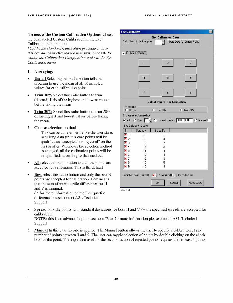
E Y E T R A C K E R M A N U A L ( M O D E L 5 0 4 ) S E R I A L & A N A L O G O U T P U T
52
To access the Custom Calibration Options, Checkthe box labeled Custom Calibration in the EyeCalibration pop up menu.*Unlike the standard Calibration procedure, oncethis box has been checked the user must click OK toenable the Calibration Computation and exit the EyeCalibration menu.
1. Averaging:
• Use all Selecting this radio button tells theprogram to use the mean of all 10 sampledvalues for each calibration point
• Trim 10% Select this radio button to trim(discard) 10% of the highest and lowest valuesbefore taking the mean
• Trim 20% Select this radio button to trim 20%of the highest and lowest values before takingthe mean.
2. Choose selection method:This can be done either before the user startsacquiring data (in this case points will bequalified as “accepted” or “rejected” on thefly) or after. Whenever the selection methodis changed, all the calibration points will bere-qualified, according to that method.
• All select this radio button and all the points areaccepted for calibration. This is the default
• Best select this radio button and only the best Npoints are accepted for calibration. Best meansthat the sum of interquartile differences for Hand V is minimal.( * for more information on the Interquartiledifference please contact ASL TechnicalSupport)
• Spread only the points with standard deviations for both H and V <= the specified spreads are accepted forcalibration.NOTE: this is an advanced option see item #3 or for more information please contact ASL TechnicalSupport
3. Manual In this case no rule is applied. The Manual button allows the user to specify a calibration of anynumber of points between 3 and 9. The user can toggle selection of points by double clicking on the checkbox for the point. The algorithm used for the reconstruction of rejected points requires that at least 3 points
Figure 26

E Y E T R A C K E R M A N U A L ( M O D E L 5 0 4 ) S E R I A L & A N A L O G O U T P U T
53
to be selected. The user is not allowed to close the calibration dialog until that condition is met. If thatcondition is not met, a message box indicating the error will be shown.
• If a 2-point calibration is preferable, the interface program has a separate menu item “Quick Calibration”under the Calibrate pull down menu. The “Quick Calibration” assumes that target points will be displayedin the upper left and lower right corners of the display (points 1 and 9).NOTE: the calibration protocol is based on the 9 point system where point 1 appears in the upper left handcorner and numbers increase to the right ending with point 9 in the bottom right corner. For example: Touse a five point calibration you must select points 1,3,5,7, and 9 for use. Or to use a four point calibrationyou must select points 1,3,7, and 9.
4. Eye Calibration Quality:
Once calibration data is acquired (a.k.a. the operator has pressed “Store Data for Current Point” whileinstructing the subject to look through calibration points) for all desired points. In addition to the trimmedhorizontal and vertical mean for each point stored, the eye tracker will calculate and display (“Spread H” and“Spread V:”) a value indicating the “quality” of each mean. For “quality”, the program currently uses theinterquartile difference, which is a robust measure of the “spread” of the data. The interquartile difference in ameasure of noise in the data.NOTE: This data represents an advanced option and is not recommended for those unfamiliar with the ASL series 5000system. For more information please contact ASL Technical Support.
5.2.6 Manual Eye Position OffsetsOVERVIEW: E5Win allows the user to add offsets to the final calculated eye position value from the Interface PCterminal. If the optics module is bumped, or calibration shifts slightly for some other reason this feature can often be usedto correct the point of gaze data without re-doing the eye calibration. There are two procedures that can accomplish an
offset.
A) Pull down the “Calibrate” menu and select “Eye PositionOffset”. Instruct the subject to gaze at one point and use the arrowbuttons on the pop up window to position the cursor over thatinstructed point of gaze. Exit the offset mode by clicking <Close>.B) Alternately, instruct the subject to fixate on point number 5of the calibration target, next select “Quick Offset” from thecalibrate menu, or select the “Eye Position Offset” pop up windowand click “Set point 5”. The computer will automatically calculatethe appropriate offset values both vertically and horizontally to movethe current gaze point to the point 5 location. TO RESET both the horizontal and vertical offsets to zero, select“Reset Offsets” directly from the “Calibrate menu, or from the “Eye
Position Offset” pop up window. Offsets are automatically set to zero when the calibration sequence isentered.
5.2.7 Saving and Loading Calibration Files (“Save As” & “Read”) Calibration and target point values are automatically saved to the default calibration file (E5000.CAL)whenever calibration or set target procedures are performed. The current values can be saved to a fileof the users choice at any time with the Save Calibration selection (under the “Calibrate” menu) asdescribed in section 4.2.3.

E Y E T R A C K E R M A N U A L ( M O D E L 5 0 4 ) S E R I A L & A N A L O G O U T P U T
54
To load target point and calibration data from a previously saved file, use the Read Calibrationselection from the “Calibrate” menu, also described in section 4.2.3.
Note: that the calibration files save only target point and calibration data. Offset values are not saved. Current offsets areautomatically zeroed whenever a calibration file is loaded.
5.3 Eye Movement MonitoringThroughout the eye monitoring session the operator should frequently look at the eye monitor to make sure the pupil andCR are being correctly recognized as described in section 5.2.4. The operator should also look frequently at the scenemonitor point of gaze display to be sure that the data makes sense.
The operator can select a white or black cursor or set of cross hairs as the point of gaze indicator by using the check boxesunder the “POG Indicator” heading on the main Interface screen. Note: that digital eye position values are continuouslydisplayed on the Interface screen (“Scene POG”). Data can be recorded as described in the next section.
When the session is complete, close any open data file (see next section).
5.4 Blink HandlingA setting on the e5000.cfg file (in the same directory as e5Win) controls the behavior of the scene monitor cursor duringblinks. The default condition causes the following behavior:
If the subject’s eye closes, or if pupil recognition is lost for some other reason, the scene POG cross hairs (or cursor) willfreeze at the current position for 12 video fields (200 msec at 60 Hz), and will then jump to a default position of (0,0). Thecursor is not visible when in the default position and will appear to have disappeared. The affect of this logic is to preventthe cursor from disappearing during blinks (usually shorter than 200 msec), but to make the cursor disappear when thepupil is lost due to extended eye closure, poor system adjustment, etc. If digital data is being recorded, as described in thenext section, the recorded gaze coordinate values also behave as described above, but the pupil diameter value is alwayszero for any data field during which a pupil is not recognized.
This feature can be modified to change the number of fields during which gaze coordinates freeze, or can be disabledaltogether so that the cursor will jump to the default position (seem to disappear) immediately upon loss of pupilrecognition. To modify this feature, look at the e5000.cfg file with a text editor, and find the line that reads
eye_position_blink_filter_value=12
To change the number of fields during which gaze coordinates freeze, change the “12” to the desired number of fields. Todisable the feature, replace the “12” with “0”. Be sure to re-save the modified file as e5000.cfg. The next time e5Win is run,or the next time “Calibrate, Read Calibration, e5000.cfg” is selected the new value will be used.
Note: that if using a 50 Hz eye camera (PAL format), 12 fields correspond to more than 200 msec, andit may be desirable to change this value to 10 fields. If using an optional high-speed camera, the valuemust be increased proportionately if it is to correspond to about 200 msec. At 120 Hz, thecorresponding value would be 24 fields, and at 240 Hz the corresponding value would be 48 fields.
5.5 Data RecordingOVERVIEW: Eye position vertical and horizontal coordinates, pupil diameter, and 16 bits of external data, called XDAT(see section 5.7), can easily be recorded on the Interface PC hard disk. In addition, event marks can be entered from thekeyboard. A field of data, consisting of the elements just listed, is recorded every 60th of a second (60 Hz update rate).

E Y E T R A C K E R M A N U A L ( M O D E L 5 0 4 ) S E R I A L & A N A L O G O U T P U T
55
If averaging has been specified, on the “System Settings” window, it is the averaged gaze coordinate data that is recorded.Remember that after a period during which a pupil was not recognized (no valid gaze measurement could be made) thefirst valid measurement is not averaged. The next measurement is averaged with just the previous valid field, and thenumber of fields averaged increases in this way until the specified value is reached. Only gaze coordinates are averaged.Neither pupil diameter, nor any other recorded values are averaged.
Open A New Data File Select “new”: from the pull down File menu or click the new file icon on the shortcut bar.
• Use the standard Windows file browser and dialog pop up to specify a directory and file name. If “Save as Type” isleft set to “Eyedat file” a “.eyd” extension will automatically be appended to the file name. This is the recommendedprocedure.

E Y E T R A C K E R M A N U A L ( M O D E L 5 0 4 ) S E R I A L & A N A L O G O U T P U T
56
• Once a file is opened, the file name will be displayed on the interface program screen just above the comment field.Initially the file name will be displayed in black letters with the message “(paused)” after the file name. Afteropening a file, type any desired text in the “Comment” field on the interface program screen and the text will besaved on the file.
To Start Recording Data Click the record icon (right arrow icon on the shortcut bar), press the “R” key or select “Start Recording” fromthe File menu. The file name will change to red letters and the message following the file name will change to“(recording)”. The disk “bytes free” indicator will also change as disk space is used up.
Mark Flags Add one of 10 manual mark flags to the data at any time by clicking one of the numbered mark buttons (iconslabeled 0 through 9) on the shortcut bar or by pressing the corresponding number keys
Stop RecordingClick the “recorder stop” icon (Black Square) on the shortcut bar, press the “S” key or by selecting “StopRecording” from the File menu. The file name will change back to black letters and the. “(paused)” message willreappear. Start and stop recording as many times as desired Eye point of gaze coordinates, pupil diameter, andXDAT values for both eyes are simultaneously
Note: Data Segments each interval of continuous data (between a start and stop recording) is referred to asa. data segment
Close Data FileSelect “close”, from the pull down File menu or click the Close Data File icon.
5.6 View Recorded DataA file viewer is provided within the interface program as a means of quickly spot checking raw datafiles to be sure something has been recorded.To use the viewer: pull down the “Misc” menu and select “View Data File”. Click the browser button (3 dots on a gray field) next to the “Data File:” box.Select the desired file in the browser box, and click “Open”. Note: If a file is currently opened, it will automatically be loaded into the viewer.Depending on file length, the file may take several seconds to load. The load can be aborted byclicking the “Close” button at the bottom of the viewer. Once the file has loaded, file headerinformation is displayed in the top section of the viewer window and data is displayed in labeledcolumns in the scrolling window on the bottom section of the viewer box. Use the standard scroll barto scroll to move through the data.
5.7 XDAT (external data)Overview: A female, 25 pin, D type connector labeled “XDAT” is provided on the back panel of the model 5000 controlunit. The XDAT connector provides access to a parallel digital port that is used as a means of inputting external data (ofthe users choice) for recording on the Interface PC hard disk along with eye tracker data. The E5000 program, along withthe other eye tracker data can record sixteen bits of parallel, TTL level, positive true data, from any source. The pin outspecifications for the XDAT connector are listed below. Each bit is interpreted as 0 when the corresponding pin is low(ground), and as 1 when the corresponding pin is high (5 Volts). The eye tracker samples the XDAT port once every eyecamera video field, and is recorded along with the eye position data from corresponding eye camera video field. Thecurrent XDAT value is always displayed near the bottom center of the interface screen.

E Y E T R A C K E R M A N U A L ( M O D E L 5 0 4 ) S E R I A L & A N A L O G O U T P U T
57
Table 5-1. XDAT connector
FUNCTION PIN NUMBER (25 pin female D type )XDAT bit 0 (LSB) 2XDAT bit 1 3XDAT bit 2 4XDAT bit 3 5XDAT bit 4 6XDAT bit 5 7XDAT bit 6 8XDAT bit 7 9XDAT bit 8 10XDAT bit 9 11XDAT bit 10 12XDAT bit 11 13XDAT bit 12 17XDAT bit 13 15XDAT bit 14 14XDAT bit 15 (MSB) 1
Ground 18,19,20,21,22,23,24,25
5.8 Auto EyedatWhen “auto EYEDAT” is enabled, on the System Settings dialog window, data recording is automatically controlled by themost significant XDAT bit (XDAT bit 15, which is pin 1 on the XDAT connector).To enable auto EYEDAT:
• pull down the Config menu and select system settings.• Check the box labeled “Auto Eyedat”.
To record data using the auto functions, first open an EYEDAT file in the usual fashion.Note: the “Record” and “Stop” buttons on the short cut bar, as well as the “Record” and “Stop” selections onthe “File” menu will be gray and inoperative.
If XDAT bit 15 is 0 (ground), the “paused” message will be displayed next to the file name to indicate that no data iscurrently being recorded. When the most significant XDAT bit is set to 1 (+5 V), a data segment will begin recording, andthe message next to the file name will change to “recording”. When the most significant XDAT bit is returned to 0,recording will stop, and the “paused” message will reappear.
Note: that setting or resetting the most significant XDAT bit is equivalent to clicking the. “Record” or“Stop” button in the normal operation mode
When the auto EYEDAT check box, on the system settings dialog window, is not checked, record and stop commandsoperate normally on the Interface program. In this case the XDAT value has no affect on data recording starts or stops.
XDAT values are recorded on data files, along with other data, whether or not the auto EYEDAT feature is being used.
5.9 Working with EYEDAT filesRecorded data can be accessed off line by:
• including a provided set of C routines within user created software to read the binary data files
• using a provided binary file description to write access software from scratch. (Source code for the C accessroutines and the binary file description are provided in a file labeled “ACCESS” on the software CD.

E Y E T R A C K E R M A N U A L ( M O D E L 5 0 4 ) S E R I A L & A N A L O G O U T P U T
58
• by using the ASL’s EYENAL data analysis program
• by converting the files to a simple ASCII format with a provided CONVERT function (part of theEYENAL data analysis program).
Note: EYENAL is described in a separate instruction manual.
VERTICAL and HORIZONTAL Eye Position CoordinatesThe eye position coordinates can be thought of as point of gaze coordinates on the scene monitor screen or onthe Interface program “Scene POG” display. The coordinate frame origin (0,0) is in the upper left corner of themonitor screen. Horizontal position values increase to about 261 at the right edge of the monitor, and verticalvalues increase to about 241 at the bottom of the monitor. Note: It is possible to have negative data values, andvalues that exceed the maximums just cited, since the subject may be looking beyond the extent of the scenemonitor field
Pupil DiameterA Zero pupil diameter value indicates that no pupil was found for that field. This may be due to an eye blink, anincorrect discriminator setting, or some other occlusion of the pupil. Pupil diameter values are not scaled tometric units. The scale factor depends on the magnification of the eye camera lens, and the eye to cameradistance. The scale factor is usually very close to 0.15 millimeters/eye-tracker-unit. To compute a precise scalefactor, see section 8.5.
Magnetic Head TrackerIf an optional magnetic head tracker (MHT) system is connected and enabled, MHT data will be recorded alongwith Eye Tracker data. The MHT data consists of x, y, and z position values, and azimuth, elevation, and rollorientation values. MHT data recorded by the e5000 program is recorded with the same binary scaling used bythe MHT device. After retrieving these values as integers, with the data access routines provided by ASL, they canbe converted to meaningful units using the scale factors listed below.
MHT type position scale factor(inches)
position scale factor(centimeters)
angle scale factor (degrees)
Ascension Bird or Flock 0.00109867 0.0027906 0.00549303
Polhemus FASTRAK 0.00360443 0.00915525 0.00549316
Polhemus 3Space orISOTRAK
0.00199835 0.00507584 0.00699423
Averaging If averaging has been specified, on the “System Settings” window, it is the averaged gaze coordinate data that isrecorded. Remember that after a period during which a pupil was not recognized (no valid gaze measurementcould be made) the first valid measurement is not averaged. The next measurement is averaged with just theprevious valid field, and the number of fields averaged increases in this way until the specified value is reached.Only gaze coordinates are averaged. Neither pupil diameter, nor are any other recorded values are averaged.

E Y E T R A C K E R M A N U A L ( M O D E L 5 0 4 ) S E R I A L & A N A L O G O U T P U T
59
5.10 17 point calibration optionThe 17-point calibration mode uses 17 calibration target points instead of the usual 9 to map a more distorted relationshipbetween the pupil and corneal reflection features on the eye and point of gaze on the scene. In most cases the normal 9points will be sufficient, but if scene image itself is significantly distorted (E.g., image from a scene camera with a wide anglelens that produces “fish eye” distortion) or the eye feature to point of gaze relation is especially complicated for some otherreason, the 17 point mode may improve accuracy. If after doing a normal 9-point calibration it is found that data isaccurate at the normal 9 calibration points, but inaccurate when the subject is looking between the locations of the normal 9points, then the 17-point mode will probably improve results.
To enable the 17-point mode, check the “17 point eye calibration” check box, on the System Settings dialog window, underthe Configuration pull down menu. Target points 10-17 should be arranged about half way between outer points of thenormal 9 point set and the center point, as shown in figure 3-3.
Procedures for setting target points and performing the eye calibration are unchanged except all 17 points must bedesignated by the Set Target Point procedure, and the subject must look at all 17 points during calibration. The EyeCalibration window is automatically closed, and computations performed, after the 17th point is entered rather than afterthe 9th point is entered.
Figure 5-4. 17 point calibration target pattern
5.11 Operation Notes and PrecautionsThe eye tracker works best when used in environments with subdued and diffuse ambient lighting. Improper ambientlighting may cause difficulty with pupil signal quality due to extraneous reflections and an overly constricted pupil. Avoidsunlight illumination of the subject’s face. If the subject must sit close to an outside window, it is best to shade the window.If possible, avoid bright light sources directly over the subject’s head, or right next to the scene being viewed by the subject,since these may cause extraneous corneal reflections. The eye tracker will not work well outdoors in sunlight due to the verybright ambient environment and too much stray IR. From the Sun’s rays

E Y E T R A C K E R M A N U A L ( M O D E L 5 0 4 ) S E R I A L & A N A L O G O U T P U T
60
It is often helpful to have low room lights while specifically illuminating the area of visual interest with auxiliary lights.“Dimmer switch” control of room lighting is often helpful.
If the scene image being viewed by the subject is a computer monitor or video monitor, it may help to use the brightnesscontrol to decrease the brightness slightly. An anti glare shield on the subject display monitor may be extremely helpful andmay improve eye tracker performance significantly.Please consult ASL technical support for additional information or for questions about a specific envirorment.
e-mail: [email protected]

E Y E T R A C K E R M A N U A L ( M O D E L 5 0 4 ) S E R I A L & A N A L O G O U T P U T
61
6 REAL TIME, SERIAL and ANALOG DATA OUTPUT6.1 Serial data outputEye tracker data can be output through an RS232 port, labeled “Serial Out” on the model 5000 Eye Tracker Control Unit.The port is set to 57600 baud, 8 data bits, 1 stop bit, no parity. Other baud rates are also possible (consult ASL for details).
6.1.1 Interface CableThe model 5000 Eye Tracker Control Unit “Serial Out” connector is a 9 pin male D type. Only “Transmit”, “Receive”,and “Ground” lines are used.
SERIAL OUT Signal
3 ------ serial data from host to 5000CU 2 ------ serial data from 5000CU to host 5 ------ Ground
An example is shown below of wiring for a cable to connect the eye tracker “Serial Out” port to a standard 9 pin COMport on a PC.
9 pin female 9 pin female
2 -------------------- 2
3 -------------------- 3
5 -------------------- 5
6.1.2 Protocol and data formatThe data output port can be set to use either a demand mode or a streaming mode. In the demand mode, the hostcomputer requests a data field by transmitting a single byte of any value. In response, the eye tracker transmits a field ofdata. After a data request is received from the host, the eye tracker PC will begin to transmit the requested field within oneupdate interval.
In the streaming mode, no data request is required. Data will continually stream from the “SERIAL OUT” port. The datais encoded, however, so that the first byte of a data field can be identified.
Encoding of the standard 8 byte data field is shown below

E Y E T R A C K E R M A N U A L ( M O D E L 5 0 4 ) S E R I A L & A N A L O G O U T P U T
62
Note that most significant bit of the first data field byte is always set (1). The most significant bit of all other bytes in thedata field are always reset (0). For the standard data set, the encoded data field is 10 bytes long rather than 8 bytes. Thehost computer must find 10 sequential bytes starting with a byte whose most significant bit is 1, then decode the data byreversing the encoding process shown above. Sample source code for decoding streaming data can be provided by ASLupon request.
The standard data buffer consists of the 8 bytes listed in Table 6-1.
Table 6-1. Standard Serial Out data field
byte description
1 Status (0 = normal, >0 = error condition)
2 Pupil diameter, most significant byte (0=loss)
3 Pupil diameter, least significant byte
4 <Used only by model 501 system with EYEHEAD Integration>
5 Point of gaze horizontal coordinate most significant byte (scenemonitor coordinates)
6 Point of gaze horizontal coordinate least significant byte
7 Point of gaze vertical coordinate most significant byte
8 Point of gaze vertical coordinate least significant byte
Note that if using the streaming mode, the above list shows the data after decoding. Each coded data field read by the hostwill consist of 10 bytes.
The system can also be set to provide alternate data buffer contents. The buffer contents and the output mode (demand orstreaming) are controlled by a value in the e5000.cfg file. View e5000.cfg (in the same directory as e5Win) with a text editor.Find the line that reads:
serial_data_output_format_type=
For the standard 8 byte output buffer, in demand mode, set the value after the equal sign to 1. For the same buffercontents, but in streaming mode, set the value to 129. For other alternatives, consult ASL. Resave the file as e5000.cfg.
6.2 Analog data outputTwo channels of analog output are available on the eye tracker control unit port labeled “Analog I/O”. One analogchannel outputs a voltage corresponding to the horizontal eye position coordinate, and the other outputs a voltagecorresponding to the vertical eye position coordinate. The voltages are proportional to the horizontal and vertical positions

E Y E T R A C K E R M A N U A L ( M O D E L 5 0 4 ) S E R I A L & A N A L O G O U T P U T
63
of the point of gaze cursor on the scene monitor and the digital gaze coordinates. Pupil diameter is not normally output,but when no pupil is recognized; the analog outputs are set to a specific default value.
Although the maximum voltage swing on each channel is from 0 to 12V, when the cursor is within the scene monitordisplay space the swing is actually from +3V to +9V. The voltage should exceed 9 V only if the subject looks beyond thepart of the scene shown at the bottom or right edge of the scene camera image, or if the system mistakes some extraneousreflection for a pupil or CR and produces nonsense data. Normally, approximately 3V from both channels correspond tothe upper left corner of the scene monitor, and 9V from both channels correspond to the lower right corner. The center ofthe scene monitor screen should correspond to about +6V.
The analog outputs do respond when in “Set target” or “Check target” point modes. For example the “Set target”function, which allows the point of gaze cursor to be controlled with the mouse, can be used to check the precisecorrespondence between any point in the scene image and the analog outputs.
Analog outputs are on pins 3 (vertical) and 4 (horizontal) of the nine pin connector, and signal ground is on pins 6-9. Theentire pinout list for the nine pin “analog I/O” connector is shown in a table at the end of this section.
The analog output will reflect averaging (number of fields to be average is specified in “System settings” dialog window,under config menu) as does the digital data and the scene monitor cursor.
The scene monitor cursor position as well as the analog values will freeze at their last position during pupil or CR loss for anumber of fields specified in the e5000.cfg file (“eye_position_blink_filter_value =”), and will then jump to a default valueuntil the pupil is once again recognized. This is to prevent blinks from causing the values to “jump”, as previouslyexplained in section 5.4. The default analog values are approximately 3 Volts (corresponding to the point of gaze cursor atthe upper left corner of the scene monitor). The default for the number of fields during which the value will freeze duringlosses is “eye_position_blink_filter_value=12”. Simply edit the e5000.cfg file (with any text editor) to change this to anydesired value. Setting it to zero will cause the values to immediately jump to the default value during any field in which thepupil is not recognized. In other words, neither the scene monitor cursor nor the analog values will freeze at their previousvalue for any period of time during pupil losses, but will go to the default position for the entire period during which thepupil is not recognized.
Note that the “blink_filter” value is a number of fields, not a time. When running at 60 Hz, 12 fields correspond to about200 msec, but at 240 Hz it only corresponds to about 50 msec. The value must be adjusted depending on the update ratebeing used. Setting the number of fields to be averaged to either 0 or 1 disables averaging.
The analog values remain “live”, rather than showing target positions, during calibration.
Table 6-2. Analog I/O connector
Pin Function
1 (not currently implemented)
2 (not currently implemented)
3 Vertical eye position
4 Horizontal eye position

E Y E T R A C K E R M A N U A L ( M O D E L 5 0 4 ) S E R I A L & A N A L O G O U T P U T
64
5 +12V
6,7,8,9 ground

E Y E T R A C K E R M A N U A L ( M O D E L 5 0 4 ) T H E O R Y O F O P E R A T I O N
65
7 THEORY OF OPERATION7.1 Pupil and CR RecognitionThe Eye Tracker optics module is designed so that the near infrared eye illumination beam is nearly coaxial with theoptical axis of the pupil camera. Because it is coaxial with the light source, the camera lens captures the partially collimatedbeam that is reflected back from the retina, and the image reaching the camera sensor is that of a back lit bright, ratherthan dark, pupil. This bright pupil image can usually be much more easily discriminated from the iris and otherbackground than could a black pupil image.
Note that the amount of reflected light that reaches the camera from the retina is approximately proportional to the fourthpower of pupil diameter. Pupil brightness therefore varies significantly with pupil diameter. Even when a subject’s pupilis at its largest and brightest, the reflection of the illuminator from the front surface of the cornea (corneal reflection orCR) is normally much brighter than the pupil. Thus the pupil can usually be distinguished from the background and theCR can be distinguished from the pupil on the basis of brightness.
When a subject’s pupil becomes very small (3 to 4 mm diameter), sections of the eyelid, cheek, or sclera that are also onthe camera field often appear as bright as the pupil. In these cases, size, shape, and smoothness criteria must be used tohelp identify the pupil.
In some cases more than one area will be as bright as the CR. If more than one bright spot will satisfy the proper size andshape criteria, the computer selects the spot closest to the pupil center as the CR. Once the pupil and CR are identified,the computer calculates their centers for use in determining eye line of gaze. Note that when the eye looks away from theilluminator more than about 25 degrees, the CR no longer appears on the cornea and cannot be detected.
7.2 Eye Line of Gaze ComputationThe separation between the pupil and the corneal reflection (CR) varies with eye rotation (change in point of gaze) butdoes not vary significantly with eye translation (head movement with respect to the eye camera). A change in pupil-CRseparation is approximately proportional to the change in point-of-gaze.
The precise relationship between eye line of gaze and the pupil-CR separation (PCR) as seen by the camera is diagrammedin Figure 7-1 for a single axis. Note that the relation reduces to
PCR K= sin( )θ (1)

E Y E T R A C K E R M A N U A L ( M O D E L 5 0 4 ) T H E O R Y O F O P E R A T I O N
66
where θ is eye line of gaze angle with respect to the light source and camera, and K is the distance between the iris andcorneal center of curvature. The corneal reflection (CR) is detectable over about a 30-40 degree diameter visual angle field.
In addition to the geometry described by the above equation, it is necessary to account for intra subject differences in
corneal shape and other second order effects. The Eye Tracker therefore computes eye azimuth and elevation angles aspolynomial functions of pupil CR separation along each axis including cross talk and corner terms. Data stored during thecalibration procedure is used by the computer to calculate the polynomial coefficients for each subject.
Figure 7-1. Relation between line of gaze and pupil/CR separation (after Merchant and Morisette, 1974)

E Y E T R A C K E R M A N U A L ( M O D E L 5 0 4 ) T H E O R Y O F O P E R A T I O N
67
7.3 Timing
A data sample is output by the eye tracker control unit for every eye camera video field. There is a transport delay ofabout 3 video fields, as shown in figure 7-2. The camera pixels charge up during 1 video field, the video data istransmitted to the system and digitized during the next field, and is processed by the system during part of the third field.The new data is available at the serial or analog output port near the end of the third field, so each data sample containsinformation that is about 3 fields old. With a 60 Hz (NTSC format) eye camera, this corresponds to a transport delay ofabout 50 ms (3/60 of a second). With a 50 Hz (PAL format) eye camera the delay is 60 ms (3/50 of a second). With anoptional high-speed camera running at 240 Hz, the delay is 12.5 ms.
Note that averaging, as specified in the “System Settings” window (see section 4.2.2), will add lag to the gaze coordinatedata, since each sample will be the average of the most recent computation and the specified number of previouscomputations.
Figure 7-2. Eye tracker timing

E Y E T R A C K E R M A N U A L ( M O D E L 5 0 4 ) F A U L T D I A G N O S I S
68
8 TROUBLE SHOOTING8.1 General ApproachThe following information is essential to determining the cause and solution to occasional system problems. In the eventthat ASL is contacted the basic concepts in this section will facilitate support.
The ASL Eye Tracking system integrates several different components so the first step in troubleshooting a problem withthe eye tracker is to determine which sub-system(s) is the cause of the problem. In most cases, the symptom of theproblem itself will lead to an immediate determination of the general location of the difficulty. From there a number ofdiagnostic tests can be undertaken to pinpoint the problem and rule out other possible causes.
8.2 Functional System DescriptionThe eye tracker consists of five sub-systems:
1. Optics. This consists of the PanTilt camera and illuminator-ring and the scene camera or scan converter.These are responsible for producing eye and scene video signals that are sent to the control unit.
2. Control Unit The model 5000 Eye Tracker Control Unit supplies power to the eye camera, scene camera,and illuminator; accepts video input from the eye and scene cameras; recognizes pupil and CR features, anddetermines their centers; computes point of gaze; superimposes edge discrimination dots and cross hairs orcursors on the eye and scene video images for display on eye and scene monitors; sends commands to thepan/tilt mechanism; receives command input from the Interface PC; and sends data to the Interface PC.
3. Interface PC. The User Interface PC uploads software to the processor (model 5000 Control Unit); sendscommands (through E5Win.exe) to the processor to adjust discriminator values, illuminator values, launchthe calibration process, etc.; receives data from the processor for display and digital recording.
4. Display This consists of the eye monitor and scene monitor.
5. Power The power supply module receives AC power from a standard outlet (100-240 VAC, 50-60Hz) andsupplies 12 VCD to the control unit.
8.3 Functional PrioritiesIt is important to understand what functions are dependent on other functions in the operation of the eye tracker system.In this way, no time is wasted servicing or troubleshooting dependent or secondary operations. The following elements ofthe system must be present in the order shown. If there is a service problem, the top-most one should be approachedfirst.
1. A successful software upload to the Eye Tracker Control Unit.
2. Successful communication between Control Unit and Interface PC (E5Win Interface program indicates“online:”)
3. A good eye monitor picture

E Y E T R A C K E R M A N U A L ( M O D E L 5 0 4 ) F A U L T D I A G N O S I S
69
4. Pupil discrimination outline on the eye monitor
5. Corneal reflection discrimination outline on the eye monitor
6. Pupil and corneal reflection recognition cross hairs on the eye monitor
7. Pupil and corneal reflection cross hairs on the Interface PC display.
8. Automatic tracking by the pan/tilt mechanism of a properly recognized pupil
9. A good scene image (if a scene camera is being used)
10. Successful eye calibration
11. Point of Gaze cross hairs or cursor on the scene monitor
12. Reasonable point of gaze cursor on the Interface PC “Scene POG” display.
13. Serial Output from the control unit is successfully communicating to an external device (if using the serialoutput)
8.4 Preliminary Trouble ShootingIf there is a problem with the eye tracker system, then the following steps should be undertaken first:
1. Check all power switches and AC connectors for all individual assemblies.
2. Check all the connections and connectors to be sure that they are all going to the proper points.
3. Check eye tracker functions in the order listed in section 8.3.
4. Contact ASL when one or more of the steps in section 8.3 is not satisfied or for clarification on any issue.
8.5 Trouble Shooting TipsThe following are tips to frequently asked questions.
1. Specular Reflection (Glasses) When a subject is wearing glasses, depending on the angle of thePan/Tilt camera and the subject, the ring of LEDs might create a specular reflection. This reflection canresult in Pupil and/or CR recognition difficulty.NOTE : there are also other possible sources of light that cause specular reflection.When presented with this situation try the following:
wipe glasses clean check environment lighting (window, overhead, display, monitor brightness, ect)

E Y E T R A C K E R M A N U A L ( M O D E L 5 0 4 ) F A U L T D I A G N O S I S
70
increase magnification (increasing the magnification will result in the camera’s field of viewbeing occupied by more of the eye and less of the surrounding features (e.g. frames).{magnification = eye to camera distance}
In an effort to eliminate the extra (specular) reflection change the present angular relationship between thesubject and the Pan/Tilt camera:
try an adjustable height chair have subject raise their chin attempt to view subject’s eye from a steeper angle
(move subject in towards the camera or raise the seat height) angle the glasses, so that the lens tilt upward and arms of the frame downward. cover the area of the frame causing the reflection (black tape)
2. Eye Calibration and Pupil/CR recognitionIf experiencing trouble with the Eye calibration consider the following:
What is the subject eye to camera distance?Optimal performance will be achieved with an eye to camera distance of 20-25 inches (50.8- 63.5cm).
Is Recognition of the Pupil and CR Solid?
• If the black circle and cross hairs indicating the CR appear to be recognizing the Pupil (i.e. the black circle isjumping up around the Pupil)a) bring the CR slider back to the left.b) attempt to reduce illumination so there is contrast between the Pupil and CR. -remember that the CR should look brighter than the Pupil
• If the white circle indicating the Pupil appears to be caving inward then drag the Pupil slider to the right, this willallow the system to detect the Pupil when it has dimmer edges.
• If the white circle indicting the pupil appears to be pulling away from the Pupil than drag the Pupil slider back tothe left, this will help the system to ignore the background.
• If the CR is not visible when inside the Pupil: When very bright pupil (prevalent in younger subject populations) is burying the CR you can increase contrastbetween the CR and the Pupil by adjusting the Iris setting. The Iris adjustment can be found in the “Setup”menu under the Pan/Tilt pull down. Moving the Iris slider to the left will result in increased contrast between thePupil and CR.
Are the Target Points spaced too far apart for the given subject to scene distance?Is the visual angle between the each target point greater than 20 degrees?
Improperly spaced target points would cause the subject to rotate their eyeball past the trackable+/- 25 degrees and cause the CR to become lost onto the sclera.- Try moving the subject away from the calibration scene plain or move your target points inward.TIP: You can determine the maximum distance at which the outer target points can be placed byhaving the subject follow a finger tip from the middle of the calibration scene to its edges andwatching the eye monitor until the CR is lost.

E Y E T R A C K E R M A N U A L ( M O D E L 5 0 4 ) F A U L T D I A G N O S I S
71
3. MHT If an error message appears If communications freeze If front light on MHT Control Unit is blinking (Ascension Flock of Birds only)
1. press <Enter> or click on “OK” to close the error box.2. Check all cable connections3. Next power off the MHT system, check the MHT baud rate setting (baud rate should be set to 19600 –
all dip switches except #1 should be pointed UP), restore power to the MHT system, and try to enableit again.
4. Be sure the correct “System Type” is selected under the MHT pull down menu5. If there is still a problem, consult ASL.
8.6 Using the model eyeOne of the accessories supplied by ASL is a model eye, or “target bar”, that can be used to simulate the image receivedfrom a real eye. It consists of a thin, 2 inch by 6 inch piece of aluminum, painted black; and containing a white,approximately 4 mm diameter circle, and a small ball bearing. The exact diameter of the white circle is actually 3.96 mm.When viewed by the eye tracker optics, the white circle looks like a bright pupil image, and the reflection from the ballbearing looks like a corneal reflection. The model pupil and corneal reflection (CR) images will not mimic the relativemotion of the pupil and CR when a real eye rotates. They do, however, provide stationary models that can be used to testeye tracker discrimination functions, to practice discrimination adjustments, and to calibrate pupil diameter.
To use the model eye, simply place it so that the white 4mm circle is at a normal eye distance from the optics, turn on theilluminator, aim the pan/tilt camera at the model eye, and adjust discriminator settings to obtain discrimination outlinesand center cross hairs, just as for a real eye (see section 5.2.4).
To compute a scale factor for pupil diameter values displayed on the computer screen, or recorded by the Interface PCprogram, first obtain proper discrimination on the model pupil, then note the pupil diameter value on the computerscreen digital display window (“PupDiam: nnn”). To compute a scale factor, divide 3.96 by this value. Convert displayedor recorded pupil diameter values to millimeters by applying this scale factor (value in millimeters = scale factor * recordedvalue).

E Y E T R A C K E R M A N U A L ( M O D E L 5 0 4 ) S P E C I F I C A T I O N S
72
9 SPECIFICATIONSMeasurement Eye line of gaze with respect to a stationary viewing surface.
Allowable eye movement Along the horizontal axis, 50 degrees or more. Along the verticalaxis, 35 degrees or more depending on optics placement andeyelids. (Field will generally be oval in shape.)
Precision Better than 0.5 degree.
Accuracy Spatial error between true eye position and computedmeasurement is less than 1 degree. Errors may increase as thehead moves significantly from its initial position. Errors may alsoincrease when gaze is beyond the outer boundary of thecalibration pattern.
Eyeglass and contact lensacceptance
Most are accepted. Eyeglasses may need to be tilted withrespect to the head if a specular refection from the glassesinterferes with the pupil image.
Ambient illumination Complete darkness to moderate illumination resulting in pupildiameters greater than 3mm. Brighter environments possiblewith special precautions.
Sampling and output rate 60 Hz (or the country’s television scan rate standard).120 Hz and 240 Hz available as options
Physical dimensions(approx.)
• Control unit is 3.25”h X 10.0”w X 10.25”d and weighs 4.5 lb.
• Pan/Tilt module is 4”h X 5.5”w X 6”d and weighs 2.75 lb.(note: shape is irregular).
E Y E T R A C K E R M A N U A L ( M O D E L 5 0 4 ) S P E C I F I C A T I O N S
73
10 Abbreviated Instructions for use of model 504 without optionalmagnetic head tracker
10.1 For each Component Setup
• Position Pan/Tilt optics, subject display, and scene camera (if scene camera is to be used) [504 manualsection 3.2.1].
• Connect system components [504 manual section 3.3]. If using composite video signal from the subjectdisplay or from a scan converter in place of a scene camera, refer to 504 manual figure 3-11 or 3-12respectively.
• Be sure the “HMO P/T” switch on the back of the Model 5000 Control Unit is set to Pan/Tilt (P/T).
• Arrange to display calibration target points on subject display [504 manual section 5.1]
10.2 For each period of equipment use
• Power up all components.
• Go to the hard disk directory, on the Interface PC, containing the EYEPOS software [504 manual section4.1].
- Upload software from Interface PC to Model 5000 Control Unit [504 manual section 4.1].
• Open Eyetracker Interface Run E5Win [504 manual section 4.2]. The “On Line” light, at the top left ofthe interface screen, should be green. If it continues to stay red consult ASL.
• Select System Settings dialog window (under Config menu) and be sure radio button is set to “Pan/Tiltoptics” [504 manual sections 4.2.1 - 4.2.2].
• Set Target Points If first use after setup, enter calibration target point positions on eye tracker software[504 manual section 5.1.1]. If this has already been done for this setup, check the target point positions tobe sure nothing has moved [504 manual section 5.1.2].

E Y E T R A C K E R M A N U A L ( M O D E L 5 0 4 ) S P E C I F I C A T I O N S
74
10.3 For each subject
• Turn on illuminator by checking the “Illuminator” box located in the upper left of the interface screen. [504manual section 5.2.2]
• Select “Manual” under the Pan/Tilt Tracking heading on the lower left of the interface screen
• Obtain Eye Image Use pan/tilt remote control (or the arrows found in the Pan/Tilt pulldown menuunder Set-Up) to aim eye camera at subject’s eye [504 manual section 5.2.2].
- If necessary, use zoom adjustment (remote control or arrows) to achieve sharp focus [504 manual section5.2.2]
• Discriminate Use the slide switches, under the Discrimination heading on the left side of the interfacescreen, to adjust pupil and CR discrimination [504 manual section 5.2.4].
• Select “Auto” under the Pan/Tilt Tracking heading in the lower left of the interface screen.
• Set Home If desired, pull down the Pan/Tilt menu and select “Set Home” to store the cameras currentposition on the eye. Subsequently selecting “Home” in the same menu will cuase the pan/tilt to return tothis learned position.
• Subject Calibration Do eye calibration: click on the Eye Calabration icon ( a 9 point pattern on a whitebackgroung) in the upper right of the interface screen. [504 manual section 5.2.5].
- At each prompt, have subject look at prompted point, be sure pupil and CR discrimination is good, click on “StoreData for Current Point”. The target points will automaticly advance as you store points.
- After calibration is complete, havesubject look at all the points to be sure scene monitor point of gaze cursor correctly indicates points. Repeat thecalibration if necessary.
• Open Data File: If desired, open data file by selecting “New” from the File menu or click on the OpenData File icon (the first icon on the shortcut bar)[504 manual section 5.5].

E Y E T R A C K E R M A N U A L ( M O D E L 5 0 4 ) S P E C I F I C A T I O N S
75
• Start Recording: Begin experiment task, and if desired begin collecting data by selecting “Start Recording”under the File menu or click the right arrow icon on the shortcut bar. [504 manual section 5.5].
• Stop & Close Data File When finished, stop recording by selecting “Stop Recording” under the File menuor click the black box icon on the short cut bar and close the file by selecting “Close” under the File menu or
using the Close icon . [504 manual section 5.5].

E Y E T R A C K E R M A N U A L ( M O D E L 5 0 4 ) S P E C I F I C A T I O N S
76
11 Abbreviated Instructions for use of model 504 with optionalmagnetic head tracker
11.1 For each Component Setup
• Position Pan/Tilt optics, subject display, and scene camera (if scene camera is to be used) [504 manualsection 3.2.1].
• Position the magnetic head tracker transmitter [504 manual section 3.2.2]
• Connect system components including head tracker [504 manual figure 3-10]. If using composite videosignal from the subject display or from a scan converter in place of a scene camera, refer to 504 manualfigure 3-11 or 3-12 respectively.
• Be sure the “HMO P/T” switch on the rear panel of the Model 5000 Control Unit is set to “P/T”[figure 2-7].
• Arrange to display calibration target points on subject display [504 manual section 5.1].
• Power up all components including magnetic head tracker (Control Unit, Pan/Tilt optics, and MHT).
• Open Interface Program and Upload software from Interface PC to Model 5000 Control Unit [504manual section 4.1].
• The “On Line” light, at the top left of the interface screen, should be green.If the On Line light continues to stay red or Upload is unsuccessful consult Trouble Shooting section ofManual or contact ASL.
• Select “Manual” under the Pan/Tilt Tracking heading on the lower left of the interface screen
• Enable MHT If MHT not already enabled (MHT x, y, z and ax, el, rl values being reported on interfacescreen below the Scene POG box), select enable/disable from MHT menu to enable MHT or click theMHT icon. [see 504 manual section 4.2.4].

E Y E T R A C K E R M A N U A L ( M O D E L 5 0 4 ) S P E C I F I C A T I O N S
77
• Select System Settings dialog window (under Config menu) and be sure radio button is set to “Pan/Tiltoptics with MHT option” [504 manual sections 4.2. 2 - 4.2.4].
• Calibrate Magnetic Head Tracker [504 manual section 5.1.4]. NOTE: this must be repeated any timethe magnetic transmitter or pan/tilt module are moved.
11.2 For each period of equipment use
• Power up all components (Model 5000 Control Unit, Pan/Tilt optics, MHT).
• Open Interface Program and Upload software from Interface PC to Model 5000 Control Unit[504 manual section 4.1].
• The “On Line” light, at the top left of the interface screen, should be green. If it continues to stay redconsult Trouble Shooting section of Manual or ASL.
• Enable MHT If MHT is not already enabled (MHT x, y, z and ax, el, rl values being reported on interfacescreen in the bottom right), select enable/disable from MHT menu to enable MHT or click the MHTicon.[see 504 manual section 4.2.4].
• Select System Settings dialog window (under Config menu) and be sure radio button is set to “Pan/Tiltoptics with MHT option” [504 manual sections 4.2.2 - 4.2.4].
• If Pan/Tilt module or MHT Transmitter have been moved since last use repeat Pan/tilt MHT calibration[504 manual 5.1.4].
• Set Target Points If first use after setup, enter calibration target point positions on eye tracker software[504 manual section 5.1.1]. If this has already been done for this setup, check the target point positions tobe sure nothing has moved [504 manual section 5.1.2].
11.3 For each subject
• Turn on illuminator by checking the “Illuminator” box located in the upper left of the interface screen. [504manual section 5.2.2]
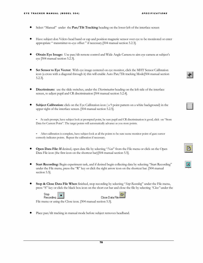
E Y E T R A C K E R M A N U A L ( M O D E L 5 0 4 ) S P E C I F I C A T I O N S
78
• Select “Manual” under the Pan/Tilt Tracking heading on the lower left of the interface screen
• Have subject don Velcro head band or cap and position magnetic sensor over eye to be monitored or enterappropriate “ transmitter-to-eye offset ” if necessary.[504 manual section 5.2.3].
• Obtain Eye Image: Use pan/tilt remote control and Wide Angle Camera to aim eye camera at subject’seye [504 manual section 5.2.3].
• Set Sensor to Eye Vector: With eye image centered on eye monitor, click the MHT Sensor Calibrationicon (a cross with a diagonal through it) this will enable Auto Pan/Tilt tracking Mode[504 manual section5.2.3].
• Discriminate: use the slide switches, under the Discrimination heading on the left side of the interfacescreen, to adjust pupil and CR discrimination [504 manual section 5.2.4].
• Subject Calibration: click on the Eye Calibration icon ( a 9 point pattern on a white background) in theupper right of the interface screen. [504 manual section 5.2.5].
- At each prompt, have subject look at prompted point, be sure pupil and CR discrimination is good, click on “StoreData for Current Point”. The target points will automatically advance as you store points.
- After calibration is complete, have subject look at all the points to be sure scene monitor point of gaze cursorcorrectly indicates points. Repeat the calibration if necessary.
• Open Data File: If desired, open data file by selecting “New” from the File menu or click on the OpenData File icon (the first icon on the shortcut bar)[504 manual section 5.5].
• Start Recording: Begin experiment task, and if desired begin collecting data by selecting “Start Recording”under the File menu, press the “R” key or click the right arrow icon on the shortcut bar. [504 manualsection 5.5].
• Stop & Close Data File When finished, stop recording by selecting “Stop Recording” under the File menu,press “S” key or click the black box icon on the short cut bar and close the file by selecting “Close” under the
File menu or using the Close icon. [504 manual section 5.5].
• Place pan/tilt tracking in manual mode before subject removes headband.