Embed Size (px)
Citation preview

Ill 1111111 ey
11111111


National Academics of Science and Engineering National Research Council of the United States of America
United States National Committee International Union of Radio Science
~ 1999 Digest USNC/URSI National Radio Science Meeting
July 11-16, 1999 Orlando, Florida
~ University of
Central Florida

II

CHAIRMAN'S WELCOME
Welcome to the City Beautiful, Orlando !
On behalf of the steering committee and myself I would like to welcome all of you to Orlando for the 1999 IEEE International Antennas and Propagation Symposium and USNC!URSI National Radio Science Meeting. Toe meeting will be held during the week of July 11-16. We have prepared a full technical program with special sessions, a variety of short courses and workshops, and an array of exhibitors. We have put together a very exciting social program that covers activities for all ages, individuals, families, groups and tastes. We also promise a banquet night with an international flavor.
Toe conference will be held at the Renaissance Orlando Resort, located next to Sea World, Universal Studios, International Drive, Wet and Wtld , and it is very close to Mickey and its Magic Kingdom! It is also about 45 minutes away from NASA's Kennedy Space Center.
This year, the National Science Foundation sponsored a special session on "Wireless Communications" and made funds available for student traveling and more student paper awards.
I hope you will do your best to attend the last APSIURSI Conference in this mil/enniwn! It will be history in the making!
Christos G. Christodoulou, General Chair Electrical and Computer Engineering Department Toe University of New Mexico Albuquerque, NM 87131-1356
Ill

STEERING COMMITTEE
General Chair Christos Christodoulou
University of New Mexico Tel: (505) 277-1434 [email protected]
Technical Program Committee Chair: Parveen F. Wahid
University of Central Florida Tel: (407) 823-2610 [email protected]
URSI Liaison Linwood Jones
University of Central Florida Tel: (407) 823-6603
[email protected] W. Ross Stone
Tel: (619) 459-8305 [email protected]
Special Sessions Timothy Durham Harris Corporation
[email protected] G. Gothard
Harris Corporation
Local Arrangements Committee Guy Schiavone
Institute for Simulation and Training Steven Vergenz
Harris Corporation
Registration Gregory Turner
Harris Corporation [email protected]
Youcheng Liu DME
Workshops/Short Courses Tom Weller
University of South Florida [email protected]
IV
Vice Chairman/Student Competition Michael Thursby
Florida Institute of Technology Tel: (407) 674-6160
Co-Chair: Timothy Durham Hanis Corporation
Finance Committee Linwood Jones
University of Central Florida Tel: (407) 823-6603
Digest Publications David Tammen
Hanis Corporation Tel: (407) 729-2622 [email protected]
Jorge Medina Medina Software, Inc. Tel: (407) 260-1676 [email protected]
Exhibits Tony Ivanov
Lucent Technologies [email protected]
James Wiltse GATech
Publicity Jay Kralovec
Harris Corporation Roben Smallwood Hewlett ...Packard
Conference Facilitators Three Dimensions
Mary Ellen Vegter, Bonnie Grosek, Theodora Dirksen
Tel: (562) 860-8180 [email protected]

APS AND URSI REVIEWERS
Constantine Balanis Jennifer Bernhard Ioannis Besieris Gary Brown Kai Chang Manohar Deshpande TimDurham Ahmed El-Z.OOghby Cynthia Furse Griffin Gothard Verlin Hibner John Huang Aldra Ishimaru Toni Ivanov David Jackson Ramakrishna Janaswamy Linwood Jones Jay Kralovec StanKubina James Lin Stuart Long Ronald Marhefka Anthony Martin Krys Michalski Amir Mortazawi
V
Cam Nguyen John Norgard Roben Paknys Yves Patenaude Wilson Pearson Andy Peterson Jeffery Philo David Pozar Sadasiva Rao Shashi Sanzgiri Tapan Sarkar Guy Shiavone Rainee Simmons Ross Stone Dave Tammen Mike Thursby Greg Turner P.L.E. Uslenghi Kathie Virga WolfVogel John Volakis Don Wilton Jim Wiltse Amir Zaghoul JaskoZec

VI

TABLE OF CONTENTS
Monday
SESSION TITLE Page
URSIB Session I NUMERICAL METHODS
AP/URS! B Session 12 SCATIERING 13
AP/URS! B Session 14 OPTIMIZATION METHODS IN EM DESIGN 23
URSIB Session 15 GUIDED WAVES 25
URSIB &F Session 25 PROPAGATION TilROUGH RAIN 37
URSIK Session 26 ELECTROMAGNETICS IN BIOLOGY AND MEDICINE 47
URSIA Session 27 NEAR FIELD ANTENNA MEASUREMENTS 57
Tuesday
URSIB Session 29 FREQUENCY DOMAIN METHODS 63
AP/URS! B Session 30 TRANSIENTS 69
URSIB Session 32 SPECIAL SESSION 75 APPLIED MATHEMATICS IN ELECI'ROMAGNETICS - I
URSIB Session 33 HIGH-FREQUENCY TECHNIQUES 85
URSIB Session 35 TIME DOMAIN ME1HODS IN ELECTRO MAGNETICS - I 97
URSIA Session 37 SHIELDING, ABSORBERS, TRANSIENT PROBING OF MEDIA 109
AP/URS! B&F Session 40 BIOMEDICAL APPLICATIONS AND EFFECTS 115
AP/ URS! F&A Session 41 PROPAGATION OVER AND TilROUGH .MEDIA 119
AP/URSIB Session 42 ARRAY OPI'IMIZATION AND SYSTHESIS 129
URSIA Session 44 PCB EM!: MICROSTRIP LINES AND COUPLERS 141
URSIB Session 45 REMOTE SENSING 147
URSIB Session46 RANDOM SURFACES 153
URSIB Session 48 SPECIAL SESSION 159 APPLIED MATHEMATICS IN ELEC1ROMAGNETICS -II
AP/URS! A Session 50 ANTENNA HUMAN 1N1ERACTIONS 169
VII

Tuesday (continued)
URSIB Session 53 MICROSTRIP AN1ENNAS AND CIRCUITS 171
URSIB&A Session 54 REFLECTOR ANTENNAS 179
Wednesday
URSIB Session 63 AN1ENNA ARRAYS 187
AP/URSIA Session 65 WIDE BANDWIDTil ANTENNAS 199
URSIF Session 67 PROPAGATION IN URBAN SCENARIOS 201
URSIB Session 68 EFHCIENT METilODS FOR MATRIX GENERATION OR 213 SOLUTION
AP/URSIA Session 75 NEAR FIELD ANTENNA .MEASUREMENT 225
AP/URS! F Session 77 FDTD APPLICATIONS III 229
URSIB Session 78 NOVEL PLANAR ANTENNAS 231
URSIB Session 79 NUMERICAL METilODS - IN1EGRAL EQUATIONS 243
AP/URSIA Session 85 DIVERSTIY RECEPTION AND MOBILE ANTENNAS 255
AP/URSIA&B Session 88 INVERSE SCATIERING: MEDIA AND TARGET 257 RECONSTRUCTION
AP/URSIA Session 89 GROUND REFLECTOR AN1ENNAS AND G/T MEASUREMENTS 261
Thursday
URSIB Session 97 ABSORBING AND IMPEDANCE BOUDARY CONDmONS 263
URSIB Session 98 RADAR CROSS SECTION 269
AP/URSIB Session 101 NUMERICAL METilODS: IN1EGRAL METHODS 275
URSID Session 102 ELECTRONICS AND PHOTONICS 277
URSIB Session 103 ELECTROMAGNETIC THEORY II 289
URSIF Session 105 REMOTE SENSING TECHNIQUES AND MODELS 299
AP/URSIB Session 106 APPLICATION OF HIGHER ORDER MODELING IN FEM 311
AP/URS! B Session 107 NU.MERICAL SCATTERING TECHNIQUES 315
VIII

Thursday (continued)
URSIB Session 108 ANTENNAS FOR WIRELESS COMMUNICATIONS 317
URSIB Session 110 NUMERICAL METHODS: HYBRID 1ECHNIQUES 329
URSIB Session 112 SPECIAL SESSION 341 CONFORMAL ANTENNAS
URSIB Session 114 INVERSE SCATIERING 351
URSIB Session 115 ANTENNA ANALYSIS 357
IX

X

Monday Morning URSI B Session 1 Coral Room A
NUMERICAL METHODS Session Chairs: T. Sarkar and. R. J. Adams Page
8 :05 Opening Remarks
8: 10 Efficient parasitic extraction for structures with non-uniform surface meshes, V. 2 Jandhyala*, S. Savage, E. Bracken, Z. Cendes, Ansoft Corporation, USA
8:30 Deconvolution of a microwave device response by FDTD and moment expansion 3 methods, G. Marrocco, F. Bardati, University of Roma, Italy
8:50 Simultaneous extrapolation in time-and frequency-domain, T. Sarlc.ar*, Syracuse 4 University, USA
9:10 ALPS: A new fast frequency sweep procedure for microwave devices, D. Sun*, 5 Ansoft Corporation, USA, J. Lee, Worcester Polytechnic Institute, USA, Z. Cendes, Ansoft Corporation, USA
9:30 Efficient computation of field panems in arbitrary cross-section waveguides, S. 6 Cogollos*, H. Esteban, R. Chismol, V.E. Boria, Universidad Politecnica de Valencia, Spain
9:50 Break
10: 10 Efficient finite element simulation of plane wave scattering by parallel gratings, C. 7 Mias*, Nottingham Trent University, UK, R.L Ferrari, Cambridge University, UK
10:30 A compact and efficient non-uniform FDTD Maxwell solver for the analysis of 8 MMICs, scanering and antenna problems in cylindrical co-ordinates, G. Shen, Y. Chen*, Hong Kong Polytechnic University, Hong Kong, R. Miura, Pennsylvania State University, UK
10:50 Spectral multi-grid for the electric field integral equation, K. Warnick*, W. Chew, E. 9 Michielssen, University of Illinois at Urbana-Champaign, USA
11: 1 O The use of meshless methods for solving electromagnetic vector scattering problems, 10 S. Buckles, S. Castillo, New Mexico State University, USA
11 :30 An efficient finite element algorithm employing wavelet-like basis functions, R. 11 Gordon, W. Hutchcraft, University of Mississippi, USA, J. Lee, Worcester Polytechnic Institute, USA

Efficient Parasitic Extraction for Structures with Non-Uniform Surface Meshes
Vikram Jandhyala*, Scott Savage, Eric Bracken, and Zoltan Cendes · Ansoft Corporation Four Station Square Pittsburgh PA 15219
Fax: 412-471-9427 E-mail: [email protected]
The accurate estimation of equivalent circuit models is of critical importance in highspeed circuit simulation. Quasi-static electromagnetic systems need to be solved in order to compute capacitance, inductance, and resistance matrices of multiport structures. Often, such problems are solved using Method of Moment (MoM) formulations. However, the solution of MoM equations entails the solution of an n x n matrix equation, where n, the number of basis functions, could be as large as 105 or 106 for realistic problems. Thus, direct solution with an associated O(n3 ) cost and O(n2 ) memory usage, is practically impossible on present-day PCs and workstations. The use of an iterative solver alleviates the computational burden somewhat, with its O(n2 ) cost per iteration. It is now well known that the Fast Multipole Method (FMM) offers substantial memory savings and permits the solution of large and realistic problems in reasonable computing times. These savings are made possible by the O(n) memory requirement of the FMM and its O(n) operation count.
The MoM typically uses compactly-supported basis functions defined on surface facets. A complex model of an interconnect or microstrip subcircuit can have several fine features that need to be modeled in greater detail than other simpler substructures. Therefore, a surface mesh can have several disparately-sized facets, with some in close proximity. Furthermore, adaptive solution, wherein surface meshes are adapted to improve solution quality, also leads to disparately-sized facets. The classical FMM, originally developed for point-like sources, can handle non-uniformly distributed facets efficiently. Less attention has been paid to its performance in handling non-uniformly sized facets. While in principle complex adaptive FMMs can be tailored to handle this problem, the simple and elegant recursive structure of the classical multilevel FMM is lost in these techniques. Moreover, automatic solution as required in commercial CAD tools is rendered more difficult.
In this work, relatively simple modifications to the classical FMM is presented that can render the algorithm suitable for application to structures with non-uniformly sized meshes. The classical FMM works by subdividing a surface into cubes at different levels, and approximating the interactions between basis functions in cubes that are well-separated. The presence of disparately-sized elements makes this task more involved. Efficiency can reduce drastically or physically wrong results can be produced. To prevent this, potential evaluation due to oversized elements is postponed to the first level where an element fits. This procedure permits the use of multipole expansions for fitting elements while using the standard Green's function for a minimal number of interactions involving large elements at a given level.
As examples of the advantage of this method, a capacitance problem involving nonuniformly refined parallel plates modeled using 20000 basis functions can be solved using less than 100 MB, whereas the classical multilevel FMM requires nearly 4 times this figure. A complex structure involving several trace lines and power planes, modeled using 52442 basis functions can be analyzed using approximately 210 MB. Simply storing the MoM matrix for this problem would have required 22 GB.
The presentation will include several simulation results to show the performance of the modified FMM. The apriori determination of FMM parameters for improved memory costs and speed will be discussed.
2

Deconvolution of a Microwave Device Response by FDTD and Moment Expansion Methods
Gaetano MARROCCO, Fernando BARDATI D.I.S.P. University di Roma Tor Vergata, Roma, Italy
The Finite-Difference Time-Domain (FDTD) method proved to be an efficient and accurate tool for full-wave modeling of microwave devices such as waveguides and antennas. However, finite computer resources limit FDTD application to the solution of Maxwellis equations in small regions. Recently, the method has been extended to larger systems by segmentation of a structure into smaller modules, each one being characterized by its own impulse-response matrix. Therefore the impulse-response restoration, from FDTD data, can play a very important role in the analysis of large composite structures.
In this paper a combined FDTD / Moment Expansion algorithm is presented for the impulse-response retrieval from FDTD data. The impulse response is obtained by means of time-domain operations only. The new method prevents illconditioned inverse Fourier processing. The FDTD analysis is applied to compute time-domain outputs of an N-port microwave device to a wide-band input waveform.
A numerical deconvolution is performed by using the Moment Expansion method, introduced by Papoulis (J. Optical Society of America, VOL. 62, pp. 77-80, 1972) for image-processing applications. The deconvolution algorithm is based on a moment expansion of the input spectrum, then the impulse response is obtained as a second-order truncated series, whose coefficients depend on input waveforms. For the application to microwave devices such as planar filters and antennas, we propose a fourth-order truncation to improve accuracy, still preserving stability. The coefficients are computed for two time-dependent excitations frequently used in FDTD computations, such as the gaussian and the derivated-gaussian pulses.
A numerical analysis has been carried out for two planar structures showing the practicability of the method.
3

SThfULTANEOUS EXTRAPOLATION IN TIME- AND FREQUENCYDOMAIN
Tapan K. Sarkar Department of Electrical Engineering and Computer Science
121 Link Hall Syracuse University
Syracuse, New York 13244-1240 Phone: 315-443-3775;Fax: 315-443-4441
http://web.syr.edu/-tksarkar
Abstract: Given the early time response and the low frequency response of a causal system, we simultaneously extrapolate them in the time and frequency domains. The approach is iterative and is based on a simple discrete Fourier transform. This method is not a true extrapolation as all the information is available a-priori but in different domains. For example, the early time data contains the high frequency information whereas the lowfrequency data contains the late time response. Hence the total information is there, the problem is how to extract it! The results are further enhanced through the Hilbert Transform., hence enforcing the physical constraints of the system and thereby guaranteeing a causal extrapolation in time. It is therefore, possible to generate information over a larger domain from limited data. It is important to note that through this extrapolation, no new information is created. The early-time and low frequency data are complementary and contain all the desired information. The key is to extract this information in an efficient and accurate manner. It is important to point out that the simultaneous extrapolation in time and frequency domains tacitly assumes a band-limited system. For example, when solving a frequency domain problem, a spatial discretization of the scatterer by elements whose dimensions are of the order of a tenth of wavelength in the medium of interest is used. In the time domain, the excitation is considered to be effectively band-limited. The highest frequency up to which the solution can be accurately obtained is limited, again for time-domain problems, by the spatial discretization of the structure. Typically , as in the frequency domain, this highest frequency is such that the spatial discretization is of the order of a tenth of a wavelength. Numerical examples will be presented to illustrate the application of this procedure.
4

ALPS: A New Fast Frequency Sweep Procedure for Microwave Devices
Din-Kow Sun1*, Jin-Fa Lee2, and Zoltan J. Cendes1
1 Ansoft Corporation 2ECE Department 4 Station Square Worcester Polytechnic Institute Pittsburgh, PA 15219 Worcester, MA 01609
This paper presents a new algorithm to compute the spectral response of microwave devices over a broad bandwidth. Over the last decade, tangential vector finite element and transfinite element methods have been developed for the solution of Maxwell equations. This discretization procedure results in a polynomial matrix equation in frequency. To compute the response of a microwave device over a broad bandwidth, one originally performed a discrete frequency sweep where the resulting matrix equation is solved at numerous frequencies. This early procedure was very time consuming. In 1993 Yuan and Cendes (Proc. APS/URSI Int. Symp. 1993, p. 196) developed a fast frequency sweep procedure requiring only one matrix solution to compute the response over the entire band. This procedure is based on Asymptotic Waveform Evaluation (A WE) which evaluates a reduced-order model of the poles and zeros of the system transfer function by forming a Taylor series approximation the response followed by Pade approximation. The technique is fast but suffers inaccuracies since it was based on a power method that converges most strongly to the nearest mode. Later, Sun (USNC/URSI Radio Sci. Meeting Dig. 1996, p. 30) presented a more reliable, adaptive Lanczos-Pade sweep (ALPS) procedure for solving the mixed-potential integral equation. Although ALPS could be adapted to solving differential equations, this requires five time-consuming matrix solutions.
In a microwave structure, the fields at the ports depend strongly on frequency. This paper first addresses the frequency dependency by computing matrix entries at several frequencies, adaptively adding more until enough frequency points are chosen to provide a good approximation. Secondly, a set of vectors is generated using the Block Lanczos method from the two lowest order polynomial matrices. Selective orthogonalization is employed to guarantee orthogonality. The Lanczos procedure is terminated as soon as a converged pole is found outside the requested frequency range. Finally, we project the polynomial matrix equation onto the space spanned by the vectors. The resulting matrix equation has a much smaller dimension than the original equation, and can be easily solved at many frequencies throughout the prescribed bandwidth. To prevent missing any resonance peaks, we avoid uniform sampling and solve for the frequency points according to the locations of the poles, previously computed in the Lanczos procedure. The whole procedure is robust and efficient, requiring only one matrix solution and usually less than 30 Lanczos vector calculations. Speed improvements compared to the discrete sweep range from 10 to 100 times, depending on number of resonance peaks encountered.
5

Efficient Computation of Field Patterns in Arbitrary Cross Section Waveguides
S. Cogollos*, H. Esteban, R. Chismol and V.E. Boria Dpto. de Comunicaciones, Universidad Politecnica de Valencia
Camino de Vera sin, 46022 Valencia, Spain Tel.: +34-96-3877820, Fax:+34-96-3877309, e-mail: [email protected]
The efficient and accurate modal analysis of arbitrary cross section waveguides has received considerable attention in the technical literature, since these waveguides are basic components of a huge number of microwave devices such as filters including tuning elements, directional couplers, diplexers, multiplexers, and so on. A very fast method for obtaining the modal spectrum of the aforementioned waveguides is presented in ( Conciauro, Bressan, Zuffada, MTT-32, n°! !,1495-1504, 1984). In this paper we present how to compute efficiently the field patterns of TE and TM modes of arbitrary cross section waveguides.
The axial component of the electrid field (TM modes) is quite easy to plot following the formula exposed in the previous reference. On the contrary, the transversal electric field (IE modes) is obtained by computing
E,(r) = - jl){t. b,[f-v L g(r,s') awaz~') di'+ k J. G,, (r,s'). t(l')w, (/')di']+ kt am:t)}
where it can be concluded that the main loss of accuracy and efficiency is related to the gradient of the Green!; function, which is represented by the slowly convergent series
g(x,y;x',y') = ~ ! ! ,;n((~x):};({T)'y') ,;n(ma,r x)s;n(!!f y) wr:1 n .. 1 mtr + !EE._
a b
This efficiency would be improved if the gradient of the Greens function could be expressed as fast convergent series. Using the Poisson summation formula, and after some mathematical
manipulations, we obtain that v g = iJg il + og y1 can be obtained as ax iJy
ag = ....!.._ f. c;o + cnOI - c~o - c~I ag = ~ f K~o + K:1 - Klloo - K~I OX 4a ··-· oy 4b a=-•
,;n[;(x-H)'x')] ,;n[f (y-(-1)' y')] CP'I = K"" ------~----=-"----~ • cosh[;(y-(-l)'y' +2nb)]- co{;(x-(-1)' x')] • -cosb[f (x- (-1)' x' + 2nb)]- co,[f (y-(-1)' y')] where these expressions converge more rapidly than the original one. Choosing a rectangular waveguide of normalized dimensions (a = 1, b = J) , and a source point at (x' = a 13,y' = b 14)
and a field point at (x =a/ 2,y = b / 2), only 3 terms are needed in the previous expressions to
reach 8 bytes of accuracy (double precision). On the other hand, the original double index series needs more than 90000 terms (300 per each index) to reach an accuracy of 5 figures. As a final aplication of the new formula deduced, we show the field patterns of the 4th and 6th TE modes of a WR-75 waveguide strongly perturbed by 4 mm rounded comers.
4th TE mode 6th TE mode ~;;:t_ ~-~
:11·----~t:"~~~ - ~ '
5 10 15 6

Efficient finite element simulation of plane wave scattering by parallel gratings
C. Mias* Department of Electrical Engineering, Nottingham Trent University, Nottingham,
Burton Street, NG! 4BU, U.K. R.L. Ferrari
*Engineering Department, Cambridge University, Cambridge, Trumpington Street, CB2 IPZ, UK
The finite element method is particularly suitable for tackling spatially periodic problems because of the simple constraint required from Floquet's theorem at periodic boundaries, while the computation reduces to one carried out over a unit cell (Nakata, Y. and Koshiba, M., Electronics and Communications in Japan, Part 2, 71, 80-91, 1988; Delort, T. and Maystre, D., Journal of Optical Society of America A, 10, 2592-260 I, 1993). We consider the two-dimensional problem of plane-wave scattering from multiple, parallel gratings. We note that it is advantageous to be able to avoid finite element meshing of the homogeneous region between the gratings (especially when the distance between the gratings is larger than the wavelength), thereby reducing the computer memory resources required in order to solve the scattering problem. The practical solution of a grating problem will invariably involved the setting up of a truncated infinite series of plane wave harmonics consistent with the grating periodicity to represent both the reflected and transmitted radiation due to an incident wave, as indeed has been so for the finite element modelling case. It is evident that for a multiple grating, say for simplicity here just a parallel identical pair separated by a uniform region (Fig.I), the transmitted waves from the (first) grating closest to the side from which the incident plane wave is approaching can be treated as waves incident upon the second grating, which in tum generates waves reflected back and incident upon the first, and so on. We set up a systematic and practical way of exploiting this phenomenon so as to connect the fields of the two gratings without meshing the region between them. Various models are considered and the correctness of their results (obtained using the reduced-mesh finite element formulation) is verified through a comparison with the results of a standard finite element solver.
incident \ plane wave\
Fig.I
7
propagating harmonics
propagating harmonics
first grating
second grating

A Compact and EfficientNon-Uniform FDTDMaxwell Solver for the Analysis ofMMICs, Scattering and
Antenna Problems in Cylindrical Co-ordinates
1Guoqiang Shen, 1Yinchao Chen*, and 2Raj Mittra 1Department of Electronic and Information Engineering
Hong Kong Polytechnic University 2Electrical Engineering Department
Pennsylvania State University
There is a variety of situations arising in the design ofmonolithic millimeter-wave integrated circuits, communication antennas including conformal antennas and phase array antennas printed on cylindrically-shaped substrates, mine locating systems, and medical microwave hyperthermia, where the geometry is primarily cylindrical rather than Cartesian in nature. Direct application of the conventional FDTD solver, which works with Maxwell!; equations in the Cartesian coordinate system, often introduces significant erroJS owing to the staircasing approximation employed in the modeling of cylindrical objects. Thus, it is highly desinble to develop an accurate and efficient FDTD Maxwell solver that is specially tailored for the analysis of cylindrical structures.
In this paper we develop a generalized three-dimensional (30) cylindrical nonuniform Finite Difference Time Domain (CNU-FDTD) Maxwell solver for the analysis of a wide array of electromagnetic problems formulated in the cylindrical coordinate system. The cylindrical FDTD solver is developed on a non-uniform grid to increase the computational efficiency whilemaintaining the desiredaccuracy. The CNU-FDTD solver is capable of analyzing monolithic millimeter-wave integrated circuits, radar cross section (RCS) computation problems, and printed microstrip antenna configurations in the generalized cylindricalcoordinate systems. In addition, to facilitate the analysis of scattering and antenna problems, we have incorporated two important features into the solvei; viz., description of the plane wave incidence and near-to-far-field transformation in cylindrical coordinates. We have employed a unified, compact and efficient formulation to describe all regions of interest including the free space, lossless or lossy isotropic medium, isotropic or anisotropic dielectric, and the cylindrical anisotropic perfectly matched layer (APML) absorber by using a complex stretched-coordinate mapping technique. The formulationdoes not require a separation of the APML region into PML faces, edges, and corners. In addition, it employs the same efficient update procedure in the non-PML regions as it does in the conventional cylindrical FDTD algoritiuQ while imposing little additional burden on the computational memory.
We have demonstrated the usefulness of the CNU-FDTD Maxwell solver by analyzing a number of representative cylindricalMMICs, as well as scattering and microstrip antenna problems. The numerical results will be included in the presentation of the paper.
8

Spectral Multigrid for the Electric Field Integral Equation
Karl F. Warnick,* Weng Cho Chew, and Eric Michielssen Center for Computational Electromagnetics
Department of Electrical and Computer Engineering University of Illinois
1406 West Green St., Urbana, IL 61801-2991
For definite elliptic partial differential equations such as Laplace's equation, multigrid methods can provide a solution in an optimal 0(1) computations per unknown. Multigrid methods have been applied to Maxwell's equations, but wavelike behavior limits the coarseness of the grids, so that multigrid is not as efficient for dynamic equations. Spectral or ray-based representations have been used to overcome this limitation for volumetric finite difference solvers (P. Vanek, et al., Tech. Rep., University of Colorado at Denver, UCD/CCM 110, Oct. 1997). In this abstract, we propose a similar method for the surface integral equations of scattering by conducting bodies.
We divide the scatterer into subgroups and represent the current solution by x = Ux, where U consists of diagonal blocks of the form
(1)
for each group, where the f n are local basis functions and X is an expansion point for the group. The spectral directions kp lie on the sphere of radius k0 •
Similar methods have been employed for impedance matrix sparsification or localization, but we use the representation as a basis for a multilevel scheme. On coarse levels, a small number of directions kp are employed, and new directions are added to refine the grid.
The fast multi pole method leads to a decomposition of the impedance matrix in the form Z ~Zn+ VTV', where Vis defined in the same was as U but includes a complete set of directions kp, and Zn represents the selfinteractions for each group. The interaction matrix for the spectral unknowns x can be written as
(2)
If the scatterer is smooth, the product UV and the translation operator T are both sparse, so that A becomes sparse. On coarse levels, the solution is represented by a small number of directions kp, and the dimensionality of A is much smaller than that of Z. On the coarsest level, A is inverted directly. The solution is then interpolated to the next level and used as the initial guess for an iterative solution method. For smooth scatterers, numerical experiments show that on the coarse levels A is well conditioned relative to Z, and the iteration converges rapidly, but the convergence of the method depends on the particular choices of directions kp at each level.
9

The Use of Meshless Methods for Solving Electromagnetic Vector Scattering Problems
Steffany Buckles and Steven Castillo The Klipsch School of Electrical and Computer Engineering
New Mexico State University Dept. 3-0, Box 30001 Las Cruces, NM 88003
The modeling of the behavior of electromagnetic waves in the timedomain is currently a topic of concern in the field of electromagnetics. Many grid methods such as the well-known FEM and FDTD have been applied successfully to many electromagnetic problems.
The Smoothed Particle Hydrodynamics (SPH) numerical method for modeling hydrodynamics problems was first described by Lucy in 1977. This particle method was invented to simulate problems in astrophysics involving fluid masses moving arbitrarily in three dimensions without boundaries. After SPH's introduction, much work has been done to further develop the method. Thus, the question arises: can electromagnetics also benefit from the gridless nature of SPH?
Previous work by the authors used the SPH method to solve for the current and voltage values along a transmission-line. In this paper, the SPH method is used to solve for the scattered electric and magnetic fields for an incident transverse magnetic (TM) wave incident on a perfect electric conducting scatterer. A perfectly matched layer (PML) is applied outside the area containing the calculations of interest to absorb the scattered waves. The PML is used with a modified version of Maxwell's equations with stretched coordinates. These added degrees of freedom from the stretched coordinates allow the boundary to have zero reflection at all angles of incidence and all frequencies. Thus, after the wave passes through the PML interface, it is attenuated and then terminated with a PEC wall. This minimizes any reflections that can travel back into the area of interest.
Further, to capture transients in the reflected waves and diminish dispersion, particle splitting was applied with the SPH method. This means that particle is split to produce additional particles in regions containing large field gradients. When these extra particles are no longer needed, the split particle recombines with the original.
10

An Efficient Finite Element Algorithm Employing Wavelet-like Basis Functions
Richard K. Gordon(*), W. ElliottHutchcraft, Jin-Fa Lee() Department of Electrical Engineering Department of Electrical Engineering t) University of Mississippi Worcester Polytechnic Institute University, MS 38677 Worcester, MA 01609
The authors have discussed the use of a finite element algorithm employing wavelet-like basis functions for the solution of electrostatics problems. (WHutchcraft, L. Harrison, R. Gordon, and J.-F. Lee, Digest of the USNC/URSI National Radio Science Meeting 1998, p. 202, June, 1998). They demonstrated that through the use ofwaveletlike functions rather than the traditional finite element basis functions, an algorithm can be obtained which, after simple diagonal preconditioning, yields matrices having condition numbers that are substantially lower than those obtained using the traditional basis functions. It was shown that the use of these basis functions presents no difficulty in the implementation of eitherNeumann or Dirichlet boundary conditions. But it was also shown that the derivation of these basis functions, especially in two and three dimensions, is quite demanding in terms of computer time and memory. This restricts the usefulness of this method.
In the present paper, the authors present an alternative approach for developing wavelet-like basis functions. Like those previously considered, these newvavelet-like basis functions are convenient for the representation of functions satisfying either Neumann or Dirichlet boundary conditions. But, as will be shown in this presentation, the derivation of these basis functions, even in three dimensions, is straightforward and makes only modest demands on computer time and memory. The use of these functions for the analysis of several problems, in both two and three dimensions, will be presented. Comparisons of the condition number, convergence rate, and solution accuracy obtained using these basis functions and the traditional basis functions will be discussed. Advantages and disadvantages of this approach in comparison to a finite difference approach or a finite element method employing traditional basis functions will be considered.
11

THIS PAGE INTENTIONALLY LEFf BLANK
12

Monday Morning JOINT AP/URSI B Session 12
SCATTERING Session Chairs: L. Carin and H. Kalhor
8:05 Opening Remarks
Koi
Page
8:10 Wedge diffraction as an instance of internal, radiative shielding, J. Grzesik, TRW 14 Electronics Systems Group, USA
8:30 Beam splitting using metallic photonic band-gap materials, G. Poilasne, P. Pouliguen, 15 K. Mahdjoubi, University de Rennes, France, L. Desclos, NEC Corp., Japan, C. Terret, University de Rennes, France
8:50 A uniform asymptotic analysis for the scattered electromagnetic pulse wave on a plane dielectric interface excited by a vector point source, T. Ishihara*, Y. Miyagawa, 16 National Defense Academy, Japan
9: 10 EM Scattering from periodic gratings of lossy conductors, H. Kalhor, State University ofNewYork, USA 17
9:30 Scattering from surfaces with small radii of curvature using the method of ordered multiple interactions, B. Browe*, G. Brown, Virginia Polytechnic Institute and State 18 University, USA
9:50 Break
10: 10 Electromagnetic scattering from arbitrary dielectric targets embedded in a layered medium: Detection of buried plastic mines, J.He*, H. Yu, L. Carin, Dulce University, 19 USA
10:30 Radiation from a circular loop in the presence of a dielectric sphere and/or a radome, H. Pattal*, E. Arvas, J. Mautz, Syracuse University, USA 20
10:50 Generalized recursive algorithm for the scattering from a spherical inhomogeneity inside a circular dielectric waveguide, T. Kushta*, K. Yasamuto, Kyushu University, 21 Japan
11: 10 Antenna gain and scattering measurement using reflective three-antenna method, T. Chu, H. Lu, National Taiwan University of Science and Technology
13

Wedge Diffraction as an Instance of Internal, Radiative Shielding
J. A. Grzesik TRW Electronics Systems Group
One Space Parle Redondo Beach, CA 90278
From the Sommerfeld multivalued scattering solution for a perfectly conducting wedge one ascertains the electric current sheets which accompany tangential magnetic field components. It becomes highly instructive then to utilize these known currents as a basis for computing the secondaiy radiated field not only throughout the wedge exterior, where, naturally, that field must reproduce all the usual diffractive results, but also across the wedge interior, where, as an extreme example of field self-consistency or else ''Bwld-Oseen eMindion," this same radiated field is obliged to counterbalance exactly the incoming plane wave excitation so as to produce a strictly null composite.
In this presentation we demonstrate radiative shielding as an inherent, ex post f atto attribute of wedge scattering; at -least as an asymptotic result far from the edge. Several distinct stages of calculation are brought into play, as follows:
1) the field radiated by a current sheet is stated in its natural coordinate system as a spectral integral whose amplitude is proportional to the Fourier transform of the current source (this standard result is subsequently adapted through coordinate rotation so as to place the radiated field from both wedge faces into one common frame);
2) from the Sommerfeld contour integral field solution we deduce kindred representations for the electric surface currents £lo-wing along both wedge faces;
3) the canonical Sommerfeld denominators which dominate these representations are evolved next into convergent power series, each term of which yields a contour integral that can be identified with a Bessel function whose order depends upon the wedge angular aperture;
4) the Fourier transforms required in Stage 1 emerge as an indexed sequence of the discontinuous Weber-Schafheitlin integral [G. N. Watson, A Treatise on the Theory of Besse! Functions, Cambridge University Press, p. 405, formulae (2) & (3)];
5) the remaining series of spectral integrals submit, term by term, to stationary phase asymptotic approximation across both interior and exrerior wedge domains;
6) and lastly, the residual summations introduced at Stage 3 are performed in a way to exhibit both the announced interior field cancellation and, on the wedge exterior, a division of space into shadow and illuminated regions, each equipped with an appropriate mix of plane-wave and diffractive field categories.
14

Beam splitting using metallic photonic band-gap materials. G. Poilasne, P. Pouliguen, K. Mahdjoubi, L. Desclos•, C. Terrel
Lab. Antennes et Telecoms, UPRES-A CNRS 6075 Universite de Rennesl, 35042 Rennes France *C&C Media Lab., NEC Co1poration, Japan
Summary: Photonic band-gap materials possess frequency bands for which the propagation of electromagnetic waves is forbidden (Yablanovitch, Phys. Rev. lett. 58, 2059, 1987). Between these band-gaps, different modes can propagate. Each mode is characterized by a particular distribution of energy inside the structure and possible directions of propagation. When excited by an incident plane wave, a part of the energy is reflected and another part is transmitted The ratio between these energies depends on the frequency. For frequency large enough, the fundamental and the upper modes are excited In this case, the energy is not only reflected or transmitted in the specular direction, but also in the directions corresponding to these upper modes. These directions can be easily calculated using the incident wavelength and the period These different behaviors can be used in order to split a incident beam into two different beams. A possible application could then be for passive repeater or even packaging
In this paper we are particularly focusing on metallic photonic band-gap materials (M.M. Sigalas et al., Phys. Rev. B, vol. 52, n°16, 1995). In a 2D square lattice composed by metallic wires, the period of the first row is changed in order to excite the upper modes. To guide the selected beams, the first row is followed by other rows with smaller period This enables to trap progressively the waves and to avoid dispersion in the structure. To design and realize such a structure, the first step is to simulate and to measure MPBG with a period changing continuously. This structure can be called log-periodic MPBG as the ratio between the period on one row and the period on the next one is constant -Fig. I-. In this case, the reflection and transmission coefficients and the diffraction in all the directions must be analyzed Different structures have been realized and their radar cross section have been measured They have also been simulated using a wire moment method (Numerical Electromagnetic Code, NEC2D, G. Burke and A. Poggio, Lawrence Livermore National Lab.). It can be noticed that the measurements of the reflection coefficient in both directions (incident plane on the side with the lower period and on the side with larger period) is completely different -Fig.2-. When incident on the low period side, the reflection coefficient is decreasing continuously whereas on the other side there are deep peaks in the reflection coefficient response. The peaks are first due to norrnal propagation modes inside the structure. They are also due to the excitation of upper modes by row on the surface of the log-periodic MPBG.
Low period side t .......•..
Large period side t Fig.I: Log-periodic MPBG composed by 4
layers with a ratio of 2.
{1~~:f-~ ! :: ~pmod-~ : . \ \'
10 15 Fr,qua,cy (GHz)
Fig.2: Log-periodic MPBG composed by 4 /ayers,from 120mm to I5mmperiod.
Conclusion: The results shows that MPBG with not constant period can be interesting in order to diffract an incident plane wave in different directions. In fact, the large period of the first row excite upper modes. These modes are then guided by the lattice and radiated in some specific directions. Applications could be for passive repeaters or even packaging at higher frequency.
15

A UNIFORM ASYMPTOTIC ANALYSIS FOR THE SCATTERED ELECTROMAGNETIC PULSE WAVE ON A
PLANE DIELECTRIC INTERFACE EXCITED BY A VECTOR POINT SOURCE
T. Ishihara* and YMiyagawa Department of Electrical Engineering
National Defense Academy Hashirimizu,Yokosuka, 239-8686, Japan
Scattered electromagnetic pulse wave in the presence of a plane dielectric interface excited by a vertical vector point source is of interest in a variety of current applications. Considerable attention has been given for many years to lateral electromagnetic waves radiated from a vertical electric dipole near the plane boundary between two dielectric media [R. W. P. King, Journal of Electromagnetic Waves and Applications, Vol.2, pp.225-243, 1988]. Also, in the acoustic area, much interests have been focused on the study of the Sommerfeld model consisting of a constant density isospeed halfspace overlying a constant density higher isospeed half-space [Stanley A. Chin-Bing and James A. Davis, J. Acoust. Soc. Am. 71(6), pp.1433-1437, 1982].
The conventional geometrical ray and lateral wave solution becomes invalid when the observation points are located in the transition region near the angle of total reflection. Recently, we have derived a uniform asymptotic solution for the scattered electromagnetic field when the electromagnetic wave radiated from the vector point source is incident on the plane dielectric interface [T. Ishihara and Y. Miyagawa, Trans. of the IEICE, Vol. J82-C-I, No.2, 1999 (Japanese)]. The uniform asymptotic solution consists of the geometrically reflected ray, the generalized lateral wave and the transition term which plays an important role near the angle of total reflection. This solution uniformly approaches the conventional totally reflected ray and lateral wave representation as the observation points move away from the source or the partially reflected ray representation as the observation points move toward the source, starting from the transition region. In this research, we shall derive the uniform solution for electromagnetic waves in the time-domain from the previously obtained uniform frequencydomain solution by applying the saddle point technique. We clarify the characteristics of each term constructing the uniform asymptotic solution. Comparison of our results with the reference solutions numerically calculated confirms the validity and utility of the proposed uniform asymptotic time-domain solution.
16

EM SCATTERING FROM PERIODIC GRATINGS OF LOSSY CONDUCTORS
Hassan A. Kalhor Department of Electrical Engineering
State university of New York New Paltz, N.Y. 12561-2499
Metallic gratings of different groove shapes have many applications in optics, electromagnetics, and microwaves because of their strong frequency dependent behavior. Many ingenious numerical analysis techniques have been developed for the analysis of such structures.
Most of the analytical methods assume that the metal is a perfect conductor and placed in air. In practice, all the scatterers are made of finitely conducting materials, and many times, they are located in a lossy medium as well. The effect of finite conductivity in gratings with triangular groove shape has been previously calculated by using a surface impedance model (Kalhor and Neureuther, J. Opt. Soc. Am., Nov. 1973). Gratings of resistive strips have also been analyzed for their potential in reducing the scattering in reflector antennas (Hall, IEEE Trans. Antennas Propogat. Sept. 1985).
In this presentation, the scattering from imperfect conducting gratings is solved by a combined wave expansion and finite difference method which gives the field within the material as well as the scattered fields. Conductor losses and their impact on the scattered fields can, therefore, be determined accurately. The scattered fields above and below the structure are expanded in terms of outgoing travelling wave modes. In the groove region, the wave equation is discretized in a finite difference form. The fields in the three regions are coupled together through the application of the required boundary conditions at the two interfaces. The solution of the system yields the reflected and the transmitted wave coefficients as well as the fields in the groove region.
17

Scattering From Surfaces with Small Radii of Curvature Using the Method of Ordered Multiple Interactions
Bryan E. Browe* and Gary S. Brown ElectroMagnetic Interactions Laboratory
Bradley Department of Electrical and Computer Engineering Virginia Tech, Blacksburg, VA 24060-0111
The Method of Ordered Multiple Interactions (MOMI), developed by Kapp and Brown (IEEE A&P, 44(5), 711-721, 1996), is an iterative numerical technique used to solve the reduced wave equation for one-dimensional rough surfaces applicable to Neumann or Dirichlet boundary conditions. In the original development, the propagator matrix of the magnetic field integral equation (MFIE) is decomposed into its lower and upper triangular components. By manipulating the resulting second kind integral equation, the resulting MOMI integral equation is obtained having a new Born term. The full solution is obtained by Neumann iteration of the MOMI integral equation.
The MOMI series has been shown to perform very well on one-dimensional, randomly rough perfectly conducting surfaces with one or two iterations of the MOMI series providing adequate convergence. The key to its success has been attributed to the fact that the most important multiple scattering contributions are included in the new Born term. Higher order multiple scattering is included in subsequent iterations of the new integral equation. This led to the thought that MOMI would also perform well on surfaces with small radii of curvature, such as a wedge-like protrusion on a plane surface because such surfaces are devoid of multiple scattering.
In this presentation, the fundamental issues involved with using an iterative technique on surfaces that display discontinuities are investigated. The surface used in the analysis can be described as a one-dimensional, perfectly conducting wedge-on-a-plane with a varying radius of curvature at the wedge tip and Gaussian tails that smoothly extend the wedge to the plane surface. This surface displays continuous ( and finite) first and second derivatives vital to the proper application of an MFIE based method. We start by investigating the variance in the far field for several incident angles and radii of curvature as the surface current sampling interval is changed. Results will be presented in terms of the magnitude of error induced for different sampling intervals and the location of these errors in the scattered field. We next investigate the effect of truncation of the surface on the accuracy of the calculated scattered field as the radius of curvature is varied. The incident angles used in our analysis will vary between normal incidence and low grazing angle (LGA) incidence. We then combine the fast multipole method (FMM) with MOMI and compare the resulting scattered fields with the results obtained with straightforward application of MOMI for several cases. Both TE and TM polarization are considered.
18

Electromagnetic Scattering from Arbitrary Dielectric Targets Embedded in a Layered Medium: Detection of Buried Plastic Mines
*J. He, H. Yu and L. Carin Department of Electrical and Computer Engineering
Duke University Box 90291
Durham, NC 27708-0291
The method of moments is utilized for the analysis ofwideband, planewave scattering from arbitrary dielectric targets buried in a lossy, dispersive layered medium, representative of soil. This model is applicable to radar-based sensing of buried plastic mines, rocks, and tunnels. To assure generality, a triangular-patch decomposition is utilized for representation of the surface electric and magnetic currents. The layered medium is accounted for through consideration of the layered-medium dyadic Greens function, efficiently evaluated here via the method of complex images.
After presenting the general theory and comparisons with the limited available data from the literature, we provide a detailed examination of several problems of practical interest. In particular, we consider the scattered electromagnetic fields induced by a realistic buried plastic mine. We examine the scattered response as a function of soil type, mine type, target depth and target orientation. We next consider several models for buried rocks, in an effort to determine the extent to which targets (mines) and clutter (rocks) can be distinguished by a radar sensor. This exercise will be undertaken as a function of sensor bandwidth.
The final set of phenomenological studies address the ltility of polarimetric techniques for distinguishing plastic mines from background clutter. In particular, it is well known that the backscattered fields from a body of revolution (BoR) have zero cross-polarized fields. Since most mines satisfy the BoR model, polarimetric sensing (no cross-polarized component) is a potential means of distinguishing mines from clutter. However, if theBoR axis is not perpendicular to the air-ground interface, these desirable polarimetric properties are spoiled, yielding non-zero cross-polarized fields. We examine this issue in detail, addressing the excitation of cross-polarized backscattered fields, as a function of target orientation (tilt), for realistic plastic mines.
19
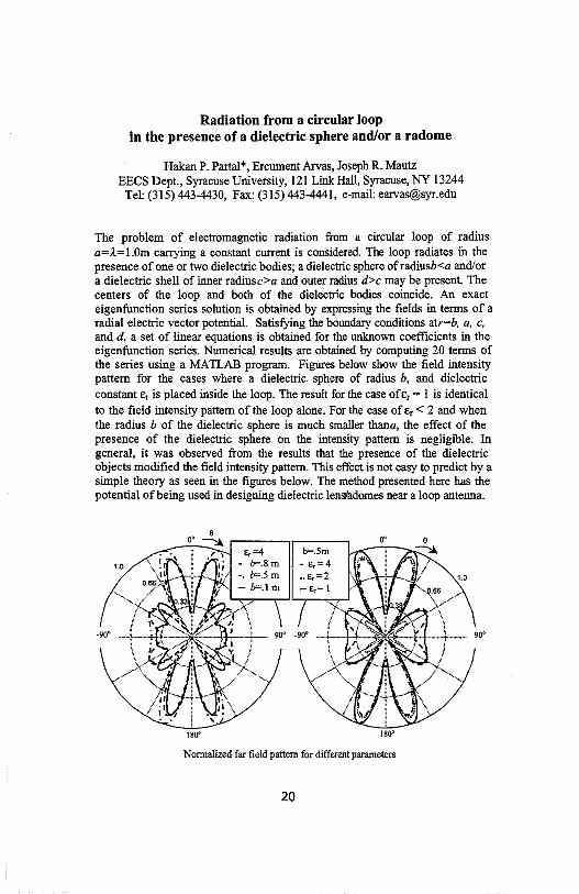
Radiation from a circular loop in the presence of a dielectric sphere and/or a radome
Hakan P. Partal*, Ercument Arvas, Joseph R. Mautz EECS Dept., Syracuse University, 121 Link Hall, Syracuse, NY 13244
Tel: (315) 443-4430, Fax: (315) 443-4441, e-mail: [email protected]
The problem of electromagnetic radiation from a circular loop of radius a=,1-=l.Om carrying a constant current is considered. The loop radiates in the presence of one or two dielectric bodies; a dielectric sphere of radiusb<a and/or a dielectric shell of inner radiusc>a and outer radius d>c may be present. The centers of the loop and both of the dielectric bodies coincide. An exact eigenfunction series solution is obtained by expressing the fields in terms of a radial electric vector potential. Satisfying the boundary conditions atr=b, a, c, and d, a set of linear equations is obtained for the unknown coefficients in the eigenfunction series. Numerical results are obtained by computing 20 terms of the series using a MATLAB program. Figures below show the field intensity pattern for the cases where a dielectric sphere of radius b, and dielectric constant Er is placed inside the loop. The result for the case ofar = 1 is identical to the field intensity pattern of the loop alone. For the case of Er< 2 and when the radius b of the dielectric sphere is much smaller thana, the effect of the presence of the dielectric sphere on the intensity pattern is negligible. In general, it was observed from the results that the presence of the dielectric objects modified the field intensity pattern. This effect is not easy to predict by a simple theory as seen in the figures below. The method presented here has the potential of being used in designing dielectric lens.ladomes near a loop antenna.
180°
b=.Sm - e,=4 •. e,=2 -e,= 1
180'
Normalized far field pattern for different parameters
20
1.0

Generalized Recursive Algorithm for the Scattering from a Spherical Inhomogeneity inside a Circular Dielectric Waveguide
T. Kushta* and K. Yasumoto Dept. of Computer Science and Communication Engineering
Kyushu University 36 6-10-1 Hakozaki, Higashi-ku, Fukuoka, 812-8581, Japan
Tel.: 81-92-642-4045, Fax: 81-92-632-5204 E-mail: [email protected]
The scattering of a guided mode by a spherical object inside a circular dielectric waveguide is studied theoretically. The field of an incident guided mode is represented in terms of the spherical vector wave functions that gives a possibility to use the conventional method of separation of variables for obtaining the scattered field by applying the boundary condition on the surface of the spherical object. The similar approach to the solution of the scattering problem of guided modes by a spherical object in an optical fiber has been used by N.Morita and N.Kumagai (IEEE Trans. MTT, 28, 137-141, 1980). However, in this paper, expressions for the total scattered power and mode conversion coefficients were determined without calculation of multiple scattering effect between the inhomogeneity and boundary of the fiber surface. We used the concept of generalized recursive algorithm developed by W.C.Chew (Waves and Fields in Inhomogeneous Media, NY:Van Nostrand Reinhold, 1990) for many-interface problem and took into account this effect. At applying of the generalized recursive algorithm, we obtained the representation of a nonsingular spherical vector wave function in terms of a continuous spectrum of cylindrical vector wave functions and used the expansion of cylindrical vectror waves in terms of spherical vector waves by R.J .Pogorzelski and E.Lun (Radio Science, 11, 753-761, 1976). In consequence, we determined the scattered field by a spherical object inside dielectric waveguide and mode conversion coefficients for this case. Numerical results were obtained for a metallic spherical scatterer inside a hollow dielectric waveguide. Particularly, it is important for the recently developed method for the study of scattering characteristics of various objects under laboratory conditions in the millimeter and submillimeter wave bands by V.Kiseliov and T.Kushta (IEEE Trans. Antennas Propagat., 46, 1116-1117, 1998), in which, a metallic sphere can be used as a reference object. As a conclusion, we want to emphasize that obtained expressions can be easily applied to the study of both the effects of impurities inside dielectric waveguides and possibility for designing of elements, for examples, resonators, mode couplers, and filters.
21

THIS PAGE INTENTIONALLY LEFT BLANK
22

l\1onday Morning JOINT AP/URSI B Session 14 Convention Center Ballroom XII
OPTIMIZATION METHODS IN EM DESIGN Session Chairs: J. Philo and C. Zuffada
8:05 Opening Remarks
8:10 Optimal design of the generalized three-parameter aperture disoibution by the emperor-selective genetic algorithm, Y. Lu, Y. Rahmat-Samii, University of California, Los Angeles, USA
8:30 An accelerated hybrid genetic algorithm for optimization of electromagnetic structures, D.Jones, K. Sabet*, J. Cheng, EMAG Technologies, USA, L. Katehi, K. Sarabandi, University of Michigan, USA, J. Harvey, The Army Research Office, USA
8 :50 Toward the synthesis of an artificial magnetic medium, J. Hagen, Universitat Karlsruhe, Germany, P. Werner*, R Mittra, D. Werner, Pennsylvania State University, USA
9:10 Non-uniform luneburg lens antennas: A design approach based on genetic algorithms, H. Mosallaei, Y. Rahmat-Samii, University of California, Los Angeles, USA
9:30 RCS reduction in planar, cylindrical, and spherical structures by composite coating using genetic algorithms, H. Mosallaei, Y. Rahmat-Samii, University of California, Los Angeles, USA
9:50 Break
10:10 Genetic algorithm optimization of cylindrical reflectors for aperture-coupled patch elements, B. Lindmark, Allgon System AB, Sweden, P. Slattman, SmartWaves International, USA, A. Ah!feldt, Allgon System AB, Sweden
10:30 Frequency extrapolation and model-based parameterization of antenna-platform radiation from CEM data, T. Su•, Y. Wang, H. Llng, University of Texas at Austin, USA
10:50 RCS inteipolation in frequency and angle using adaptive feature extraction, Y. Wang*, H. Ling, University of Texas at Austin, USA
11: 1 O Determination of surface currents by back propagation of field measurements, P. Harms, J. Maloney, M. Kesler, E. Kuster, S. Blalock, Georgia Tech Research Institute, USA, G. Smith, Georgia Institute of Technology, USA
11 :30 Simulated annealing optimization applied to antenna arrays with failed elements, J. Redvik, Ericsson Microwave System AB, Sweden
Page
11:50 Multicriteria optimization ofloaded antennas via genetic algorithms, K. Yegin, A. 24 Martin, Clemson University, USA
23

Multicriteria Optimization of Loaded Antennas via Genetic Algorithms
Korkut Yegin and Anthony Q. Martin Department of Electrical and Computer Engineering
Clemson University, Clemson, SC, 29634-0915
In a typical loaded antenna optimization problem, one usually considers antenna power gain, overall system gain, and voltage standing wave ratio as performance measures over the optimization frequency range. Simultaneous maximization of antenna power gain, system gain, and minimization of voltage standing wave ratio is often the goal of optimization. Depending on the frequency band of interest, these performance measures may exhibit many local maximums and minimums that generally cause the optimization routine to terminate at a suboptimum result or even fail to converge. All of the performance measures can be combined into a single optimization problem if scale adjustments among them are properly set. However scale adjustments over a wide frequency band are extremely difficult to achieve and create many instabilities in the optimization process.
In our formulation of the problem, we have considered the minimization of voltage standing wave ratio as a nonlinear constraint to the maximization of system gain and antenna power gain. An exact penalty function is formulated and used to handle this nonlinear constraint in the maximization problem. Penalty functions are often used to convert a constrained optimization problem to an unconstrained one. By doing so, one penalizes the unconstrained optimization problem if one of the constraints in the original problem is violated. In the present optimization problem of loaded antennas, one also has linear inequality constraints on the optimization variables that usually represent component values of the loaded antenna/matching network system. The inequality constraints ensure that the optimized components remain within practical limits. These linear inequality constraints are not converted to a penalty function but can be handled easily with the proper choice of the optimization technique.
An optimization technique based on genetic algorithms is used in the present method. Depending on how far the iterated solution is away from the design goal, the penalty function is formulated to take different forms. However, the differentiability and continuity conditions of the penalty functions are always preserved to ensure smooth transitions into penalty regions. The type of penalty functions and their effect on the loaded antenna optimization, and the optimized configurations obtained through the application of the proposed approach, will be discussed in detail in the presentation.
24

URSI B Session 15 Monday Afternoon
Coral Room C
GUIDED WAVES Session Chairs: A. Elsherbini and A. Yakovlev Page
1: 15 Opening Remarks
1:20 Photonic bandgap structures for minimizing the coupling between microstrip lines, V. 26 Rodriguez-Pereyra, A. Elsherbeni, C. Smith, University of Mississippi, USA
1 :40 Analysis and reduction of crosstalk on ribbon cables, A. Elsherbeni, C. Huang, C. 2 7 Smith, University of Mississippi, USA
2:00 Full-wave analysis of nonplanar lines on layered medium using MPIE and complex 28 images, J. Bernal, F. Medina, R Boix, University of Seville, Spain
2:20 Spectral domain analysis of thick tranSmission lines using orthogonal polynomials, A. 29 Mathis, Ansoft Corporation, USA
2:40 Microstrip lines with finite conductivity in a layered medium, C. Lee, National 30 Changhua University of Education, Taiwan, J. Kiang, National Chung-Hsing University, Taiwan, C. Hsu, Da-Yeh University, Taiwan, J. Lin, National Changhua University of Education, Taiwan
3:00 Mode structure and field distribution for guiding radar system based on H-field leaky 31 coaxial cable, N. Blaunstein, Z. Dank, Magal Security Systems, L<lt., Israel, M. Maki, C. Hill, Stellar-Senstar, Inc., Canada
3:20 Leakage properties of open 3D anisotropic waveguides, A. Topa*, C. Paiva, A. 32 Barbosa, Instituto Superior Tecnico, Portugal
3 :40 Complex characteristics impedance of printed tranSmission lines under power-leakage 3 3 conditions: A new theory, N. Das, Polytechnic University, USA
4:00 Investigation of mode interaction on planar dielectric waveguides with loss or gain 34 using complex-plane singularities of the dispersion function, G. Hanson, University of Wisconsin-Milwaukee, USA, Y. Yakovlev, North Carolina State University, USA
4:20 Properties of TE surface waves in absorbing layers, P. Ya Ufimtsev, R. Ling, Nonhrop 35 Grumman Corp., USA
4:40 Orthogonality and Green's functions for modes in periodic waveguides with 36 asymmetric cells, M. Jiang, T. Tamir*, Polytechnic University, USA
25

PHOTONIC BANDGAP STRUCTURES FOR MINIMIZING THE COUPLING BETWEEN MICROSTRIP LINES
V. Rodriguez-Pereyra, A. Z. Elsherbeni, and C. E. Smith Electrical Engineering Department,
The University of Mississippi University, MS 38677
atef@ olemiss .edu
The coupling between microstrip lines is one of the most important factor in the design of todays computers, microwave and communication devices, and digital electronic systems in general. The high-speed performance of digital electronic systems always relies on accurate exchanges of digital signals between systems and subsystems. Most digital electronic systems consist of circuit boards and other electronic devices, which are often interconnected by various types of printed microstrip lines. Different techniques have recently been used to minimize the coupling between microstrip lines. Among these techniques is the use of air notch, lossy or PEC doping material, PEC cover, and related combinations. One of these recent studies concluded that the combination of PEC doping and PEC cover significantly reduce far and near end coupling for frequencies up to 100 GHz. However, for very dense circuits, the use of PEC doping and the introduction of PEC covers, introduces many fabrication difficulties. An alternative approach is to modify the dielectric substrate and/or the ground plane in order to achieve the same objectives.
Photonic bandgap (PBG) structures are generally infinite periodic structures of dielectric materials that prevent propagation at certain frequencies. For finite rather than infinite PBG structures the propagating signal is attenuated over a specified frequency band. In the past, PBG structures are used extensively in the optical region of the frequency spectrum. Recently the properties of these structures are scaled down to the microwave region and are used with single microstrip transmission lines as filters.
In this paper, the finite difference time domain (FDTD) technique is used to analyze the electromagnetic coupling between two printed microstrip transmission lines. Several configurations of photonic dielectric substrate are used to effectively increase transmission on the active line and reduce near and far end coupling on the passive line. Preliminary results show improvement of the transmission byapproximately 5 dB on the active line and 10 dB reduction of the far end coupling for all frequencies from O to 20 GHz.
26

ANALYSIS AND REDUCTION OF CROSSTALK ON RIBBON CABLES
AtefZ. Elsherbeni, Chun-Wen Paul Huang, and Charles E. Smith Electrical Engineering Department,
The University of Mississippi University, MS 38677
atef@ olemiss .edu
With the recent advancements of integrated circuit and digital circuit technologies, computers and digital electronic systems can operate at very high speed. The high-speed performance of digital electronic systems always relies on accurate exchanges of digital signals between systems and subsystems. Most digital electronic systems consist of circuit boards and other electronic devices, which are often interconnected by various types of ribbon cables. These interconnecting cables can be characterized as multiconductor transmission lines, which allow for propagation of multi-bit digital signals. However, these high-speed digital signals consist ofa very wide frequency spectrum, normally from very low frequency ( even down to DC) to hundreds of MHz (or even several GHz). The high frequency spectra of a digital signal will couple between transmission lines, which results in unwanted crosstalk and distortion of signals. Crosstalk not only degrades the high-speed electronic systems by limiting the propagation speed at the cabling system interfaces, but also causes incompatibilitybetween digital systems and subsystems. Recently, efforts have been invested in the design of crosstalk cancellation circuitry for high-speed electronic systems. Instead of investing major efforts in designing complicated crosstalk cancellation circuits, the design of a low crosstalk cabling system may be a more economic and a more effective alternative.
In this paper, the finite difference (FD) and finite difference time domain (FDTD) techniques are used to analyze the electromagnetic coupling between lines in a multi-conductor ribbon cables. Several effective approaches to reduce the crosstalk in interconnecting cables and connectors are presented. The preliminary results show that for two types of ribbon cables, a reduction of coupling over 20 dB at low frequencies is observed. Additionally, a 5dB reduction ofboth near and far end crosstalk over a range of frequencies up to 300 MHz is achieved at a 4 wire cable connector ends. Few cases are compared with measurement results. The agreements between the numerical and measured results confirm the accuracy of our analysis method.
27

Full-Wave Analysis ofNonplanar Lines on Layered Medium Using MPIE and Complex Images
J. Bernal , F. Medina, R.R. Boix University of Seville
Grupo de Microondas. Dept. Electr6nica y Electromagnetismo. Facultad de Fisica
Avda Reina Mercedes s/n, 41012 Sevilla (SPAIN) Tel: +34 5 4552891, Fax: +34 5 4239434, e-mail:[email protected]
The design of microwave monolithic integrated circuits is currently tending to the use of higher frequencies with increasingcomponents density and complexity. The analysis of this typeof circuits demands a full-wave modeling. Moreover, it is also necessary to take into account the presence of conducting strips close to each other as well as the non-negligible thickness of the metallizations. In addition, the conductors may present a trapezoidal cross section owing to the fabrication process. Conductors with other types of crosssections must also be handled, i.e. if we desire to analyze transmission lines in discrete wire technology for high-speed applications.
In the present work, a fast and accurate technique is presented to analyze open microstrip lines consisting of several arbitrary shape conductors placed above a multilayer dielectric substrate. The dielectric layers may beuniaxially anisotropic with its optical axis in the z direction. The technique presented here is based in the integral equation method. The mixed potential electric field integral equation (MPIE) is formulated in the space domain for the structure aforementioned and solved by using the method of moments {::.G.Hsu et al. IEEE Tran. Microwave Theory Tech. Vol 41,pp. 70-78, Jan. 1993.). The most relevant contribution of our approach concerns the way of obtaining the kernel of the integral equation: a very accurate approximation of the two-dimensional spatial domain Green's functions for the scalar and vector potentials is obtained for any source-field point pair in closed form. To accomplish this, part of the spectral domain kernel of the integral equation is accurately approximated by using complex images. This approximation is specially well suited since the approximating functions represent the spectral version of cylindrical waves. Moreover, the images have not to be recomputed for each guess value of the propagation constant in the root search process. The inverse Fourier transform of the approximated spectral version of the kernel can be analytically performed by using a "two-dimensional Sommerfeld identity". The surface wave poles contribution to the kernel is extracted out and separately evaluated in a quasianalytical form when necessary. In this way, the complex image technique becomes a useful tool to obtain the dispersion curves ofnonplanar lines in a fast and accurate way.
28

Spectral Domain Analysis of Thick Transmission Lines Using Orthogonal Polynomials
Andrew W. Mathis Ansoft Corporation
Boulder Microwave Division 3800 Arapahoe Ave., Suite 250
Boulder, CO, 80303 email: [email protected] TEL: (303) 541-9525, x24
The spectral domain method offers a fast and robust method for determining the electrical properties of transmission lines. One of the advantages of the spectral domain method is the ease of using entire domain basis functions. If one accounts for the edge singularities, the entire domain basis functions converge rapidly to a solution. For vanishingly thin metals, the longitudinal current displays an inverse square root singularity at the edges, which is the well known Chebyshev weighting function. This leads naturally to using Chebyshev polynomials to discretize the current distribution. In many of today's high speed applications, the conductor thickness is on the same order as the conductor width or the distance from a ground plane and must be taken into account. Unfortunately, entire domain functions do not extend easily to thick transmission lines, and for these cases, one is typically forced to use subsectional basis functions.
However, Gegenbauer polynomials are orthogonal with respect to the weight functions typically associated with the thick conductors and can be used to represent the current distribution. In the presented analysis a spectral domain integral equation is formulated for the current on a microstrip transmission line of rectangular or trapezoidal cross-section. The longitudinal current on the transmission line is discretized using Galerkin's method and Gegenbauer polynomials and the appropriate weight function. One can think of Gegenbauer polynomials as a generalization of Chebyshev and Legendre polynomials where one can vary the order of the endpoint singularities from inverse square root (Chebyshev) to non singular (Legendre). As with Chebyshev and Legendre polynomials, Gegenbauer polynomials also have a convenient spectral domain representation, Bessel functions of the first kind. If the transverse currents are needed, they can be discretized using Legendre polynomials and current continuity enforced.
The presentation includes a brief overview of the methodology of the GegenbauerGalerkin method to solve the integral equation. Since in layered media, vertical basis functions can be problematic, approximate methods for slightly thick conductors and exact methods for very thick conductors are discussed. In addition, results are presented for single and coupled microstrip lines of rectangular and trapezoidal cross sections. Limitations and possible extensions of this method are also discussed.
29

MICROSTRIP LINES WITH FINITE CONDUCTMTY IN A
LAYEREDMIDIUM
1Ching-Her Lee, 2Jean-Fu Kiang, 3Chung-I G. Hsu, and 4Jui-I Lin 1•4 Department of Industrial Education
National Changhua Universit)Of Education Changhua, Taiwan 500, ROC
2 Department of Electrical Engineering National ChungHsing University
Taichung, Taiwan 402, ROC 3 Department of Electrical Engineering
Da-Yeh University Changhua, Taiwan 515, ROC
In microwave integrated circuits, the used interconnect and line structures are most!: striplines. The conductor loss, as the operating frequency is getting higher, should be take into account to accurately predict the electromagnetic behaviors. To compute the conductc loss, a perturbation approach has usually been used. The conductor loss is treated as perturbation in the lossless case, and is evaluated by using the surface resistance and th surface current. Other approaches, such as the integral equation method that is derived usin the equivalent surface impedance in the boundary condition, or as the approximate metho proposed by Wheeler that is based on the incremental inductance rule, are also used t, calculate the conductor loss. All these methods assumed that the strip thickness is larger tha the skin depth. In practical application, however, the advanced fabrication process may resu in conductors that are very thin, so that conventional perturbation method could lose it accuracy in computing the dissipation of the rnicrostrip lines. Later, Kiang [J. F. Kiang, IEE Trans. Microwave Theory Tech., Mar. 1991.] proposed an volume integral equatioi formulation using the dyadic Green's function to solve for the dispersion relation of the sing] and the coupled conductor strips. The microstrips considered in this technique can be ver thin and their cross sections can be of arbitrary shape.
In this work, an electric-type dyadic Green's function for planar multilayered medi based on the transmission-line network analog along the axis normal to the stratification i developed [K. A. Michalski and J .R. Mosig, IEEE Trans. Antennas Propagat., Mar. 1997]. Ii deriving the system dyadic Green's function, the number of the background dielectric Jaye: are assumed arbitrary, and the dielectrics can be lossy. In addition, the rnicrostrip lines ca reside in different layers, and the cross sections can be of arbitrary shape. The formulation i then used to solve for the dispersion characteristicoof the conductor strips with finite conductivity and thickness in multilayered media. To obtain numerical solution, the cros section of the conductor strip is divided into small ceUs. Then, the eigenmode electric field: on the cross section can be represented by a set of pulse basis functions. FoUowing Galerkin method of moments, the same set of basis functions is chosen as the testing functions. Th, Galerkin's procedure will result in a matrix equation, from which both the phase constant an the attenuation constant are solved. In this study, the multilayered structures with conductc thickness on the order of the skin depth are of primary interest. The dispersion characteristic of conductors having rectangular, trapezoidal, and fish-eye-like cross sections are examine, The effects on conductor loss due to different cross section shapes are also investigated.
30
Mode Structure and Field Distribution for Guiding Radar System Based on H-field Leaky Coaxial Cable
N. BlannshteinCI), Z. Dank(!), J. SczepanskiC2), M. Maki(2), and C. Hi1J{2)
(l)Magal Security Systems Ltd., Israel {2)Stellar-Senstar, Inc., Ottawa, Canada
Abstract The theoretical and experimental investigations of mode structure and field distribution of a
H-field leaky coaxial cable, as a guiding radar system, are presented for various artificial and natural local inhomogeneous conditions along and across to the cable system. The possible generation of a complicated interference picture of such a radar pattern caused by different kinds oflocal inhomogeneities are discussed theoretically and studied experimentally.
In order to predict the properties of leaky cable systems we utilized a simple two-mode model that seems to explain the basic propagation mechanisms quite successfully [1, 2]. We performed a preliminary analysis for the external fields produced by some of coaxial cables. The principal purpose of that investigation was to predict the fraction of the power radiated in the external region and converted into a surface wave supported by the dielectric jacket. Different structures such as leaky cables shielded by a finite number of unidirectional or counterwound helices, and a cable which combines the unidirectional helical tape with a longitudinal slot were studied within the framework of the simplified model.
Another very important task was to investigate the possibilities of predicting and controlling the directional features of the radiation pattem The study of these problems requires the derivation of special analytical and numerical techniques. By using these techniques we predicted an optimal leaky system with the required parameters including directional properties. These techniques permit us to analyze the clutter effects and to optimize the sensitivity of the system. Some related preliminary results were obtained by use of the analytical and numerical technique. In order to explain the dependence of the field intensity on the transverse coordinate we used the concept of the surface wave, which is characterized by an exponentially decreasing field. The decreasing rate and the localization area of the field are shown to be functions of the external mode propagation constant The propagation constant is dominated by the properties ofthe insulation jacket, perturbed by losses in the earth and other objects in the nearest environment, and does not depend strongly on the cable burial depth in the case of subsoil installation.
Apart from a regular case of a surface wave supported by a single wire in free space, we have investigated the wave field distribution in a complicated environment, such as dielectric or conductive walls located near the cable. The results confirm that the effect of an inhomogeneous environment can be significant, and by varying the location of the cable we could control the radiation pattem
References [l] N. Blaunstein, Z. Dank, and M. Zilbershtein, Proc. of 27th European Microwave Conference '97, Jerusalem, Israel, Sept. 8-12, 1997, pp. 175-178. [2] N. Blaunstein, Z. Dank, and M. Zilbershtein, Proc. of Int. Symp. ofElectromag. Compat., EMC'98 ROMA. Rome, Italy, Sept. 14-18, 1998, pp. 458-463.
31
Leakage Properties of Open 3D Anisotropic Waveguides
Antonio L. Topa*, Carlos R. Paiva, and Afonso M. Barbosa Departamento de Engenharia Electrotecnica e de Computadores
and Instituto de Telecomunicai;oes Instituto Superior Tecnico
Av. Rovisco Pais, 1049-001 Lisboa, Portugal. Tel: +351-1-8418479, Fax: +351-1-8417284, E-mail:[email protected]
The study of the guiding properties of open dielectric waveguides is very important, namely for several applications in millimeter wave and optical frequencies. Lateral confinement of energy requires the use of 3-dirnensional (3D) waveguides. The analysis of 3D dielectric waveguides is a topic of considerable research since the original paper of Marcatili (E. A. J. Marcatili,Bell Syst. Tech. J., 48, 2071-2102, 1969). For a certain number of years the work on this topic has been focused on the guiding properties of these waveguides. More recently Peng and Oliner (S-T. Peng and A. A. Oliner,/EEE Trans. Microwave Theory Tech., 29, 843-855, 1981) have put in evidence that, under appropriate circumstances, some of these waveguides may leak energy. The occurrence of leakage can seriously disturb the waveguide performance due to crosstalk but may also be used for the operation of some novel devices.
In the design of many photonic components, like electrooptical devices, anisotropic materials are commonly used (R. Miirz, Integrated Optics - Design and Modeling, 42-44, 1995). Therefore, it is important to extend the analysis of Peng and Oliner to include the leakage effects of anisotropic waveguides. The present paper is focused on the analysis of anisotropic rib waveguides and presents new results related to the propagation of leaky waves. These structures consist of a central region built of an anisotropic film over an isotropic substrate, and two identical lateral regions with the same structure as the central one, but with a smaller thickness of the uniaxial film. The propagating surface waves will bounce back and forth horizontally in the inside region located between the two outside regions, undergoing total internal reflection at each bounce.
In order to simplify the analysis, we have only considered a uniaxial film with vertical optical axis since, under this assumption, the elementary surface waves of the central region are pure TE and TM. These waves will couple at the strip sides and thus leakage may occur due to the coupling effect. Using an approximate analysis in which the radiation modes are neglected (A. L. Topa, C. R. Paiva, and A. M. Barbosa, Microwave Opt. Technol. Lett., 5, 602-606, 1992), we show that, under certain circumstances, the TE and TM coupling gives rise to leakage in the form of an exiting surface wave and the longitudinal wavenumber of the waveguide propagating mode becomes complex. Numerical results are presented, which show the effect of the material anisotropy on the attenuation constant of the first leaky wave modes.
32

Complex Characteristic Impedance of Printed Transmission Lines Under Power-Leakage Conditions:
A New Theory
Nirod K. Das Weber Research Institute/ Department of Electrical Engineering
Polytechnic University Route 110, Farmingdale, NY 11735
It is now well kn.own that, under appropriate conditions, printed transmission lines can leak power in a distributed manner to the surrounding medium. The propagation behavior of such transmission lines have been studied over the past several years. But, only recently serious attention is being given to the modeling of their characteristic impedance, following some of our early work (N. K. Das, IEEE Trans. MTT, April 1996; also in 1996 IEEE MTT-Symp. ) The methods commonly used to model the characteristic impedance of standard TEM or quasiTEM lines, such as the power-current, the power-voltage, or the voltage-current methods, will not apply when power-leakage exists. This is because the leaky fields are strongly non-TEM in nature, and exhibit non-standard exponential growth in the transverse plane (which means the cross-sectional power is infinity). We will discuss in this presentation a new theory, called "the wave-number perturbation theory," which would be applicable for leaky as well as non-leaky situations. The basic theory is derived based on a rigorous field theory of the transmission line, supported by physical interpretation using an equivalent distributed circuit model. The propagation constant of a leaky line is perturbed to see various changes in the transmission-line fields. The resulting information is then used to derive or extract a model for an equivalent characteristic impedance, which is shown to be useful and accurate in practical situations. Computed results using the new theory are validated by comparison with independent data. Results for selected geometries of strip-type as well as slot-type leaky printed transmission lines will be discussed, demonstrating the new theory for diverse leakage situations.
33

Investigation of Mode Interaction on Planar Dielectric Waveguides with Loss or Gain Using Complex-Plane Singularities
of the Dispersion Function
George W. Hanson Department of Electrical Engineering and Computer Science
University of Wisconsin-Milwaukee 3200 N. Cramer Street
Milwaukee, Wisconsin 53211
AlexanderB. Yakovlev Department of Electrical and Computer Engineering
North Carolina State University Raleigh, North Carolina 27695-7914
On lossless isotropic planar waveguides the discrete proper modes of propagation form independent TE and TM sets such that there is no mode coupling or interaction between modes. In the event of material loss or gain, mode interactions are possible leading to a complicated spectrum and apparent non-uniqueness of the modes. In this work we analyze for the first time the cause of these modal interactions by studying the simplest canonical planar waveguide which exhibits these effects, the symmetric-slab waveguide. We show that mode interactions are due to the migration of complex frequency-plane branch points, associated with specific wave phenomena, with varying loss or gain. As these singularities move near the real frequency axis they influence modal behavior for time-harmonic (real-valued) frequencies, crossing the real axis at some critical value of loss or gain. It is shown that as time-harmonic frequency varies, passing above, below, or through these branch points results in different modal behavior. Passing above or below, and near to, the branch point yields mode coupling behavior, while passing through the branch point results in modal degeneracy. The result of this branch point migration is that the association of a particular mode with a certain branch of the dispersion function depends not only on the value of material loss or gain, but on the order in which physical parameters of the problem are varied. Three different branch-point types are identified and discussed, which leads to an understanding of the relevant wave phenomena and to a method for organizing the mode spectrum in a consistent and unique manner.
34
Properties of TE Surface Waves in Absorbing Layers
P. Ya. Ufimtsev, R.T. Ling
Northrop Grumman Corp. 8900 E. Washington Blvd.
Pico Rivera, CA 90660-3783
Abstract
Properties of surface waves in lossless guiding structures are well known. However, this is not the case for surface waves in absorbing structures with large losses. The problem was investigated recently for TM surface waves in real absorbing layers (R.T. Ling, J.D. Scholler, and P.Ya. Ufimtsev, PIER, 19, 49-91, 1998). In this presentation, we will show new results for TE surface waves in absorbing layers with the same test material. All basic characteristics of surface waves are demonstrated. They include attenuation and propagation constants, electric and magnetic losses, complex Brewster angles, phase and amplitude fronts ofBrillouin waves inside layers, phase and energy velocities. Detailed computations confirm the upper cutoff phenomenon for TE surface waves as reported recently by the authors (P.Ya. Ufimtsev and R.T. Ling, JINA98 -International Symposium on Antennas, Nice, France, November 17-19, 1998). A similar phenomenon was discovered earlier for TM waves (R.T. Ling, J.D. Scholler, and P.Ya. Ufimtsev, 1997 North American Radio Science Meeting, Montreal, Canada, July 13-18 , 1997, Digest, p. 200; 1998 USNCIURSI National Radio Science Meeting, Atlanta, Georgia, USA, June 21-26, 1998, Digest, p. 277). Contrasting features of this phenomenon between TE and TM waves are noted. The application of impedance approach is justified for thin layers supporting single propagating mode. In the framework of this approach, the excitation of surface waves by the aperture-limited plane waves is investigated. Launching efficiency and the relative distribution of the power transmitted by surface waves outside and inside absorbing layers are found.
35

Orthogonality and Green's functions for modes in periodic waveguides with asymmetric cells t
Mingming Jiang and Theodor Tamir*
Department of Electrical Engineering, Polytecltnic University 5 MetroTeclt Center, Brooklyn, NY 11201
Tel.: (718) 260-3421, FAX: (718) 260-3906, e-mail: [email protected]
Applications in optoelectronics, antenna technology and other areas have recently motivated the study of scattering and guiding of waves by structures that exhibit a multilayered form in the x (vertical) direction and a periodic variation along the z (horizontal) direction. Most of these studies have explored configurations with periodicity cells that are symmetric only, and they have viewed the fields supported by such configurations in terms of modes whose transverse variation is along z and propagate along x. However, many realistic situations involve asymmetric c·ells; furthermore, additional physical insight can often be gained by using modes that propagate in the horizontal direction, i.e., along z rather than x. We have therefore considered structures having asymmetric cells and examined field representations in terms of fields that propagate along z.
We have found that an appropriate representation of fields propagating along z is in terms ofFloquet-type modes that obey a bi-orthogonality condition if the periodicity cells are asymmetric, i.e., wave propagation along z is then generally different from that along -z. This bi-orthogonality condition reduces to the conventional orthogonality relation only at the symmetry planes of structures consisting of symmetric cells. On the other hand, the conventional transmission-line relations at selected cross-sectional planes (along z) hold also for asymmetric-cell configurations provided the pertinent lines are described by two different characteristic impedances (one each for the two +z and-z directions). We have therefore extended transmission-line formalism to such situations. By applying this formalism, we have then developed a Green's function procedure that readily provides the fields excited by arbitrary sources.
The asymmetrical Floquet representation reported here facilitates a considerably stronger analytical approach to problems that have been addressed by mostly numerical methods in the past. Typical examples of realistic situations will also be presented and discussed.
t Work supported by the National Science Foundation under Grant No. ECS-9522078.
36

Monday Afternoon JOINT URSI B & F Session 25
PROPAGATION THROUGH RAIN Session Chairs: L. Ariet and Q. Liu
1:15 Opening Remarks
Koi
Page
1 :20 A wet antenna model for correcting Ka band propagation measurements, R. Acosta, 3 8 NASA Lewis Research Center, USA
1 :40 A comparison of methods for minimizing or compensating for rain fade at Ka band, 39 C. Cox*, R. Acosta, NASA Lewis Research Center, USA
2:00 Narrow angle diversity research using ACTS Ka-band signal with two USAT ground 40 stations, C. Emrich*, R. Acosta, NASA Lewis Research Center, USA
2:20 Fade slope analysis using the seven-site ACTS propagation data at 20 and 27 GHz, C. 41 Grinder, Stanford Telecom, USA
2:40 Propagation models comparison with measurements taken in a tropical rain zone 42 using the ACTS system, S. Johnson*, R. Acosta, NASA Lewis Research Center, USA
3:00 Break
3:20 Dynamics of rainfall in Brazil, E. Couto de Miranda, L. da Silva Mello, M. Pontes, 43 Pontifical Catholic University of Rio de Janeiro, Brazil
3:40 Frequency scaling of rain attenuation for terrestrial microwave links in Malaysia, M. 44 Islam, J. Chebil, T. Rahman, University of Technology Malaysia, Malaysia
4:00 Modeling multiple-frequency microwave scattering from hydrometeors using the 45 finite-difference time-domain method, F. Hastings, Stanford Telecom, USA
37

A Wet Antenna Model for Correcting Ka Band Propagation Measurements
Roberto J. Acosta NASA Lewis Research Center
Cleveland, Ohio 44070 USA
Phone: 216-433-8016 e-mail : [email protected]
Abstract
This paper describes a theoretical and an experimental treatment of the contribution of wet reflector antennas to the signal path losses in a Ka-band communication system. At Ka-band, the effect of wet antenna surfaces is not negligible, with or without the application of hydrophobic material measured attentions are in the order of several dBs (R. Acosta, Radio Sci., 222, 1999). The objective of this paper is to describe a simple theoretical model to form the basis for correcting fade attenuation measurements made by using reflector antennas at Ka-band. Also a comparison with experimental data (R. Acosta, 4th Ka Band Utilization Conference, Italy, 1998) is also presented.
The amount of water in ground reflector antennas (reflector and feed radomes) can cause additional signal loss (up 4-5 dBs) from the expected propagation attenuation due to rain at Ka-band. This is one reason that the standard techniques for predicting rain fade statistics (propagation models) are not aligned with ACTS Ka-band RF beacon measurements. The problem of wet antenna can be described as high perturbation on the feed standing wave ratio and in contrast the reflector losses can be explained by an additional scattering losses and absorption due to raindrops size at the surface of the reflector. In this paper, extensive measurements and a simple physical optics/transmission line model are provided as a guideline on designing antennas considering the effects of antenna wetting.
The developed theoretical model gives a first order approximation for the ground antenna designer to minimize the effects of wet antennas particularly is system with low system margins. In order to minimize the effect of wet reflectors, the dielectric thickness of the reflector needs to be minimized in order to reduce the losses in the presence of a water layer. The feed losses can be minimized by adding an extended radome cover on the topside of the feed to protect the phased center of the horn being exposed to water.
38

A Comparison of Methods for Minimizing or
Compensating for Rain Fade at Ka Band
Cristina Cox* and Roberto J. Acosta NASA Lewis Research Center
Cleveland, Ohio 44070 USA
Phone:216-433-6640
e-mail : [email protected]
Abstract
Satellites operating in the Ka band experience signal attenuation much more severe than satellites operating in lower frequency bands. While factors such as clouds and gases can degrade the signal, rain is the most dominant impairment to propagation in this frequency range (R. Acosta, 3rd Ka Band Utilization Conference, Italy, 1997). Knowing how to effectively compensate for such signal degradation is critical to satellite system design. Although some of these impairments can be overcome by oversizing the ground station antennas and high power amplifiers, the current trend is using small(< 20 inches apertures), low-cost ground station (< $1000.) that can be easily deployed at user premises. As consequence, most Ka-band systems are expected to employ different forms of fade mitigation that can be implemented easily and at modest cost.
Much research has been done in the areas of compensating for rain fade and minimizing its effects. Launched in 1993, the NASA Advanced Communications Technology Satellite (ACTS) has been used as a testbed for experiments addressing rain fade compensation in the Ka band for more than 5 years (C. Cox and T. Coney, 4th Ka Band Utilization Conference, Italy, 1998). This paper will present the results of various methods tested by ACTS to minimize or compensate for rain fade. An overview of the ACTS Adaptive Rain Fade Compensation Algorithm and its performance will be provided. This algorithm incorporates burst rate reduction and forward error correction to compensate for rain fade. The impact of implementing ground site diversity as a means of compensating for rain fade will be examined. Both short-distance and large-distance diversity data will be presented. Methods for modifying antenna design to minimize the fade effects caused by a wet antenna will be reviewed. This will include both the impact of water on different portions of the antenna and various .methods of shielding the antenna from rain. For each method presented, a brief description of the experiment will first be provided, followed by a summary of the results obtained.
39

NARROW ANGLE DIVERSITY RESEARCH USING ACTS KA-BAND SIGNAL WITH TWO USAT GROUND STATIONS
Carol Emrich* and Roberto J. Acosta NASA Lewis Research Center
Cleveland, Ohio 44070 USA
Phone: 216-433-6640 e-mail : [email protected]
Abstract
The congestion of the radio spectrum below 18 GHz is stimulating greater interest in teh 20/30 GHz band. However, due to the shorter wavelengths of these frequencies, the atmosphere can greatly influence transmission of signals between Earth/space stations. At elevation angles above 10 degrees, generally only rain attenuation and possibly tropospheric scintillation effects are significant, depending on propagation conditions. To overcome effects of the Earths atmosphere on the 20/30 GHz frequency, a through understanding of these phenomena is required The experiment described in this paper is an investigation of narrow angle spatial diversity using two USATs located 1.2 km apart. The diversity ground station measure the strength of this signal with power meters located at each site. Rainfall and atmospheric moisture data are collected throughout the experiment and correlated with signal attenuation.
Two ultra small aperture terminal (USAT) ground stations separated by 1.2 km in were operated in the receive mode for this experiment, using a continuous Ka-band signal tone sent from Cleveland ground station with the Advanced Communication Technology Satellite (ACTS) steerable beam. The Signal attenuation is compared at the two sites and diversity gain is calculated. It was collected over 15 fade events collected over a period of two months. Diversity gains ranging from 1 to 16 dB were observed. These data exceed diversity model gain predictions in every fade event, for this separation distance. The nature of Florida!; subtropical rainfall, with its intense small diameter rain cells, is discussed as a factor in these findings.
Because of the small size of the USAT ground station with its 0.35 meter antenna and the projected low cost, spatial diversity is desirable method for compensating for rain fade and thereby increasing satellite link availability. These preliminary results show narrow angle diversity, which is of greatest commercial interest for providing quality services in sub-tropical and tropical areas, found that existing popular propagation model under-predicted diversity performance. Several recommendations for improving models are provided.
40

Fade Slope Analysis Using the Seven-Site ACTS Propagation Data at 20 and.27GHz
Cynthia Grinder, [email protected] Stanford Telecom 45145 Research Place Ashburn, Virginia 20147
Above about 15 GHz, system performance for communications links will be limited by the fading caused by precipitation. Not only is the duration of the fade important but also the dynamics of the fade. Fade slope is a measurement of the attenuation rate of change with respect to the time and has the units of decibels per second. Fade slope predictions are important to satellite systems designers in order to help them design power control algorithms and error correction techniques to minimize the effect of link outage for their systems.
This paper analyzes fade slope for seven sites throughout the US and Canada using Advanced Communications Technology Satellite (ACTS) propagation data at 20 & 27.5 GHz (see, for previous studies, Julie Feil, Proceedings of the IEEE, vol. 85, No. 6, 926-935, June 1997). The sites studied include Alaska, British Columbia, Colorado, Florida, New Mexico, Oklahoma, and Virginia. These sites represent a wide range of rain regions and elevation angles. Five years of data (January 1, 1994- December 31, 1998) were used. Annual fade slope statistics as well as seasonal fade slope statistics from various attenuation ranges were examined. The statistics illustrate the relationship between fade slope, fade level, transmission frequency, and elevation angle. Also since fade slope is a measurement of the slow-varying rain attenuation rather that the fast-varying scintillation different filters were studied and implemented.
41

Propagation Models Comparison with Measurements
Taken in a Tropical Rain Zone Using The ACTS system
Sandy Johnson* and Roberto J. Acosta NASA Lewis Research Center
Cleveland, Ohio 44070 USA
Phone: 216-4 3 3-6640 e-mail: [email protected]
Abstract
NASAs Advanced Communication Technology Satellite (ACTS), launched in September 1993, is demonstrating new technologies in communications systems in the Ka frequency bands. One such technology is the operation of small size ( < 2.5 m) ground stations capable of Tl (1.55 Mbps) data rates. The ground stations operate in a Time Division Multiple Access (TDMA) mode using ACTS on-board baseband processor. The advanced technologies of KA-band systems, such as high gain spot beams, allows user ground stations to carry acceptable traffic with small antennas and low power transmitters resulting in lower cost satellite ground stations. Industry has shown interest in these terminals for commercial markets including direct product distribution and Internet.
In this paper, typical link margins for a VSAT operating in a tropical rain zone is reviewed. The influence of propagation at Ka-band on the VSAT system and the effects on performance are presented. A comparison of several popular propagation models with actual rain attenuation measurements using the VSATs for a period of 2 years are presented.
The ACTS VSAT system was designed with 5dB uplink and 3 dB downlink clear sky margins. In addition to the clear sky margin, the ACTS VSAT maintains a good quality of communications during period of rain by applying forward error correction codes and reducing the data rates to produce an additional 10 dB of extra margin. This system margin has demonstrated to be sufficient to achieve a system availability of at least 99.9 % for all US rain zones (T. Coney and C. Cox, 2"d Ka-band Utilization Conference, Italy, 1996).
42

Dynamics of Rainfall in Brazil
E. Couto de Miranda, L.A.R. da Silva Mello and M.S. Pontes
Centre for Telecommunication Studies Pontifical Catholic University of Rio de Janeiro
Rua Marques de Sao Vicente 225, Ala K. 'f1 Floor Gavea, Rio de Janeiro, RJ
Brazil 22453-900 Tel: +55215299255, Fax: +55212945748, e-mail: [email protected]
Abstract
In this paper, the dynamic aspects of rainfall are investigated for four sites in Brazil. Three of the sites are located within the Brazilian Amazonia: Manaus (-3, equatorial, ITU-R type P), Ponta das Lajes (-3, equatorial, ITU-R type P) and Belem (-1, super-humid equatorial, ITU-R type P) and the fourth one is located in Rio de Janeiro (-23, tropical, ITU-R type N). The sites ofManaus and Ponta das Lajes are separated by 13km and form a site diversity experiment. The dynamics of the rainfall rate correspond to the study of the number of events of rainfall and their individual durations, given a certain rainfall rate threshold. This type of statistics provide more information than the cumulative distribution alone, because the statistical behaviour of different rainfall regimes, such as convective and stratiform rain, can be clearly separated (as can be seen, for instance, in the paper of Timothy, Mondal and Sarkar, Int. J. Satell. Commun.,16, 53-57, 1998). Although some research bas been conducted on the subject (e.g., the paper mentioned above, Misme, J.Recb. Atmos., 8, 1-2, 1974 and Barbaliscia and Fedi, Proc. URSI Com. F., La Banle, 131-138, 1977, to name a few), an agreement on what should be the best fit for the distributions of event durations and the number of events is far from being reached. This uncertainty calls for more results from different parts of the world, all contributing towards the discovery of a pattern that eventually would lead to a comprehensive model. Results include the parametric estimation of the rainfall events duration, the time between events and the number of such events based on a Weibull distribution for the events and an exponential distribution for the times between events. The choice of these two distributions is based in our choice of pursuing a model that would be both simple and physically sound. These results are compared with results from other authors. The distributions of the number of rainfall events during the day are also presented, covering the values of 5, 50 and IOOmm/h. Since two of the sites located in the equatorial region are separated by only 13km, the daily distribution of rainfall events may help identify the possible benefits of using site diversity at that location
43

Frequency Scaling of Rain Attenuation for Terrestrial Microwave Links in Malaysia
Md. Rafiqul Islam, Jalel Chebil & TharekAbd. Rahman Wireless Communication Research Lab
Faculty of Electrical Engineering, University ofTechnology Malaysia Locked Bag 791,Skudai, 80990 J.B
Fax: 607-556-6272, E-mail: [email protected]
The most fundamental obstacle encountered in the design of communication systems at millimeter waves is attenuation due to rain. Attenuation due to rainfall can severely degrade the radiowave propagation at frequencies above 10 GHz. Since the tropical climate in Malaysia is characterized by high intensity rainfall, then the knowledge of the rain attenuation at the frequency of operation is extremely required for the design of a reliable communication system at a particular location. Because of a limited amount of reliable long-term rain attenuation statistics are available, frequency scaling method of rain attenuation can be used to estimate the rain attenuation statistics at a desired frequency from measured attenuation values at another frequency. The attenuation at the base, or reference, frequency is known from prior measurement. Frequency scaling techniques can be classified into two types. The first type uses single frequency attenuation statistics, while the second one uses dual frequency attenuation statistics. Many scaling models have been developed using either technique. The derivation of these models is based on either theoretical or experimental approach or both.
In order to compare between various models proposed for frequency scaling of rain attenuation, Universiti Teknologi Malaysia (UTM) in collaboration with Ericsson started a campaign to collect rainfall and rain attenuation data in Malaysia. Experimental mini-links at 23 GHz, 26 GHz and 38 GHz were installed at UTMs main campus in Skudai on April 1998 and collection of rain attenuation data started at the same time. All antennas are 0.6m diameter with horizontal Polarization and a separation distance of 300m. In addition, a fast tipping bucket type rain gauge of 0.5mm sensitivity and with one-minute integration time was installed along the experimental mini-link for the collection of the rain rate data. Also data collection of rain attenuation started on early March 1998 in Kuala Lumpur over an existing microwave links at 23 GHz with vertical polarization and 0.91km hop length.
This paper briefly reviews the available scaling models which use either single or dual frequency statistics and investigate the accuracy of these models using the one year measured rain attenuation data obtained in Malaysia.
44
Modeling Multiple-Frequency Microwave Scattering from Hydrometeors Using the Finite-Difference Time-Domain Method
Frank D. Hastings, [email protected] Stanford Telecom 45145 Research Place Ashburn, Virginia 20147
For a number of years, there has been interest in modeling the scattering characteristics ofhydrometeors such as rain, hail, and snow (see, for an overview, T. Oguchi, Radio Science, vol. 16, No. 5, 691-730, 1981 and A. R. Holt, Radio Science, Vol. 17, No. 5, 929-945, 1982). The presence of the hydrometeors in the propagation path results in attenuation, phase shift, and depolarization in the scattered fields. This phenomenon is of interest in numerous applications including communications and weather remote sensing.
In this paper, the finite-difference time-domain (FDTD) method is used to calculate forward scattering amplitudes for rain and falling ice and snow particles. In many cases, the shapes and sizes of the particles of interest are such that analytical methods (exact or approximate) are not applicable; hence, numerical methods must be used. In previous work, scattering amplitudes have been calculated using a variety of frequency domain methods, including the integral equation method, the extended boundary condition method, point matching, and various other techniques. The main disadvantage these methods share is that they must be applied separately for each frequency of interest. The FDTD method permits simultaneous calculation at multiple frequencies in a single application of the method.
To obtain a coherent field transmission characteristic for a random distribution of particles, the scattering amplitudes are averaged over size and canting angle distributions. Using a standard formulation (G. Brussaard and P.A. Watson, Atmospheric Modeling and Millimeter Wave Propagation, 1995), a transmission matrix can be constructed to model the presence ofhydrometeors in the propagation path.
The results presented here describe the scattering characteristics for various particle types. The scattering amplitude results are validated using Mie theory for spherical particles. Additional comparisons are included for nonspherical particles using selected data from the literature. The frequency dependence of the scattering characteristics for both single particles and random distributions is also examined.
45

THIS PAGE INTENTIONALLY LEFT BLANK
46

Monday Afternoon URSI K Session 26 Labrid
ELECTROMAGNETICS IN BIOLOGY AND MEDICINE Session Chairs: E.J. Rothwell and Jian-Ming Jin
1: 15 Opening Remarks
Page
1 :20 An implantable ante1U1a for communication with implantable medical devices, C. 48 Furse, H. Lai, C. Estes, A. Mahadik, A. Duncan, Utah State University, USA
1 :40 Characterization and optimization of experimental E-field probes with FDTD, A. 49 Christ, K. Pokovic, T. Sclunid, N. Kuster, Swiss Federal Institute of Technology (ETII), Switzerland
2:00 An image reconstruction algorithm for ultrawideband microwave radar technology SO applied to breast cancer detection, S. Hagness*, University of Winconsin, USA, M. Popovic, A. Taflov, Northwestern University, USA, J. Bridges, Interstitial, Inc., USA
2:20 Assessment of an ultrawideband microwave radar technology for early detection of 51 cancer in radiographically dense breast tissue, S. Hagness*, University of WisconsinMadison, USA, J. Bridges, Interstitial, Inc., USA
2:40 A numerical study of control algorithms for MR-monitored microwave hyperthermia 52 systems, M. Kowalski, J. Jin, University of illinois, USA
3:00 Break
3:20 A numerical study of the signal-to-noise ratio of magnetic resonance surface coils, M. 53 Kowalski, J. Chen, J. Jin, University of illinois, USA
3:40 In vitro effects of 60 Hz magnetic fields on cell differentiation and proliferation, E. 54 Rothwell*, K.Chen, J. Suk, C. Chang, J. Trosko, G. Chen, B. Upham, W. Sun, Michigan State University, USA
4:00 Reduction of hazards of magnetic fields of power lines, H. Kalhor, R Kalhor, State 55 University of New Yolk, USA
4:20 Research of non-heating millimeter waves for increasing of effectiveness generically 56 valuable breeds of animal, V. Murav'ev, A. Tamelo, U. Byahun, Belarusian State University of Informatics and Radioelectronics, Republic of Belarus, N.H. Fedosova, Belarusian Agricultural Academy, Republic of Belarus
47

An Implantable Antenna for Communication with Implantable Medical Devices
Cynthia Furse, Hock Kwong Lai, Cory Estes, Amit Mahadik, Andrew Duncan Department of Electrical and Computer Engineering
Utah State University Logan, Utah 84322-4120 Phone: (435) 797-2870 FAX: (435) 797-3054 [email protected]
Abstract
Numerous medical devices are implanted in the body for medical use. These include pacemakers and defibrillators, hormone pumps, and nerve stimulators. With the advancement and miniaturization of bioelectronics it is likely that the array of implantable medical devices will continue to expand in the years to come. Medical implants are intended to stay in the body for many years or decades, and it is often necessary to communicate with the device to download data about the health of the device or its batteries or the health of the patient, or to upload changes in settings or new procedures specified by the doctor. It is even conceivable that the patient could control the setting of his or her medical implant with the touch of a button from a wireless device.
The design of antennas that can communicate with implantable devices is an interesting and challenging problem. The antenna must be small and long-term biocompatible, preferably able to be mounted on existing implant hardware or to utilize part of the hardware itself. The antenna must be electrically insulated from the body so as not to short out and be ineffective, and it must be efficient so as not to excessively drain the batteries. It must not exceed the safety guidelines for power deposited in the body, and should be insensitive to external EM noise. Some applications (such as data up or down load) could use a high-gain directional system, whereas other applications (such as monitoring while the patient is mobile and active) would require a more isotropic system.
This paper describes several potential antenna designs for this project. The ISM frequency of 433 MHz was used. The antennas are microstrip designs such as the ones shown in Figure I below. The antennas would be mounted in the chest or hip cavity on the titanium battery pack of the medical implant, which is approximately 2x2x0.5" in size. This box acts as the ground plane for the microstrip antenna and is in direct contact with the body. The microstrip antenna is built of a layer of silicone rubber on one 2x2" side of the battery pack, with a titanium microstrip as shown in the designs below. This is then coated with either epoxy or silicone rubber. These materials are chosen for biocompatibility. Other rubber substrates, with higher dielectric constants, could potentially be used to shrink the design size. These antennas were simulated using XFDID software in a realistically implanted case. The input impedance, radiation pattern, gain, and SAR distribution were analyzed. Prototyping and testing of these designs is presently underway.
Feed
u Feed Fed
Figure I: Several configurations of implantable microstrip antennas
48

Characterization and Optimization of Experimental E-Field Probes with FDTD
Andreas Christ, Katja Pokovic, Thomas Schmid and Niels Kuster Swiss Federal Institute of Technology (ETH)
8092 Zurich, Switzerland Phone:+41-1 632 2736, Fax:+41-1 632 1057, e-mail: [email protected]
Introduction Since ensuring compliance with safety limits has lately become a product liability issue, another quality of requirements is placed on instrumentation and procedures for experimental dosimetry with respect to liability and overall precision. The highly nonhomogenous field distributions encountered in lossy biological tissue pose great demands on the small isotropic E-field probes commonly used for local dosimetry. Field disturbance, spherical isotropy and spatial resolution are crucial parameters for assessing the probe performance in a specific application. While many papers describe the characteristics of the sensors and the lines in small E-field probes, little literature is available on the various field distortions occurring between the incident field and the fields measured by the probe sensors. Data on commercially available probes are generally scarce and the probes are often used in an inappropriate manner, resulting in large measurement uncertainties.
Objectives The objectives of this project were to derive the effects of the signal detection and the readout on the probe characteristics and to develop suitable methods to fully evaluate and characterize the uncertainty of the probe for the usage in lossy tissue materials. This includes l) field distortion by the probe, 2) boundary effects, 3) field deflection inside the probe, 4) eddy current effects, 5) spatial resolution and 6) field detection and readout. Their influence on the probe performance was shown both with measurements and with numerical simulations of the probe. Design criteria for minimizing the probe errors were given as well.
Method An E-field probe for measurements in tissue simulating liquid (tip diameter 6.8mm) was analyzed. Several numerical simulations and measurements were used to separate and characterize the different effects. The simualtions were performed with a high resolution FDTD-model of the probe. The minimum cell size was 0.125 mm*0.125 mm*0.125 mm, which allowed a very detailed representation of the probe tip. The numerical analysis was complemented by measurements using a high precision 6-axis robot for the positioning of the probe.
Conclusions The field disturbances and deflections in the probe have a huge impact on the isotropic response of the probe. Commercial probes with three geometrically orthogonal sensors showed spherical isotropy deviations of up to ±3.4dB in brain simulating tissue. Building isotropic probes is only possible if all disturbing effects are analyzed and minimized for the specific media. Tip size, probe materials, sensor location and sensor angle alignment must be matched for optimum performance. The influence of the boundary effects, the field distortion and the eddy currents was determined by the simulations. The isotropy errors which were found for the numerical model could be confirmed with the measurements. The optimized probes in the study showed spherical isotropies of ±0.4dB to ±0.2dB in homogenous fields. Since some of the effects depend on the field polarization or the field gradient, further error reduction is possible by using the probes in restricted configurations. For a detailed evaluation of the probe uncertainty, the specification of all relevant field effects is necessary.
49
An Image Reconstruction Algorithm for Ultrawideband Microwave Radar Technology Applied to Breast Cancer Detection
Susan C. Hagness* Department of Electrical and Computer Engineering
University of Wisconsin Madison, WI 53706-1691 [email protected]
Milica Popovic a:nd Allen Taflove Department of Electrical and Computer Engineering
Northwestern University, Evanston, IL 60208
Jack E. Bridges Interstitial, Inc.
1937 Fenton Lane, Park Ridge, IL 60068
The feasibility of confocal microwave imaging based on ultrawideband radar technology for detecting early-stage breast cancer has been demonstrated recently (Hagness et al., IEEE Trans. Biomed. Eng., 45, 1470-1479, Dec. 1998). The physical basis of this technology is the large dielectric contrast between malignant tumors (and associated vascularization) and adjacent normal breast tissue. Thus, even a small malignant tumor has a significantly large radar cross section. The microwave sensor is comprised of an electronically scanned antenna array placed at the surface of the breast. A single ultrawideband antenna element is excited and the backscattered waveform is collected. This is repeated in sequence for the other elements in the array. As a post-processing step, the set of backscattered waveforms are variably time-shifted to achieve coherent addition for a desired virtual focal point within the breast.
In this paper, we report an image reconstruction algorithm for the breast cancer detection system. The algorithm is based on a systematic scanning of the synthetic focus from point to point within the breast, resulting in a microwave image of the internal breast tissue. We apply the algorithm to backscattered waveforms collected from two-dimensional FDTD simulations of the antenna array applied to a heterogeneous breast model. In the FDTD models, the antennas are excited with very short (< 100 ps) pulses to achieve good range resolution. Our models include the dispersive dielectric properties of malignant and adjacent normal breast tissue as reported in the literature. We explore the use of dispersion compensation techniques to overcome the pulse-broadening effects of the dispersive breast tissue. For those breast models containing a tumor, our resulting images vividly indicate the presence of the malignant mass.
50

Assessment of an Ultrawideband Microwave Radar Technology for Early Detection of Cancer in Radiographically Dense Breast Tissue
Susan C. Hagness* Department of Electrical and Computer Engineering
University of Wisconsin Madison, WI 53706-1691 [email protected]
Jack E. Bridges Interstitial, Inc.
1937 Fenton Lane, Park Ridge, IL 60068
X-ray mammography is currently the most effective screening method for detecting nonpalpable early-stage breast cancer in women over the age of 50. After menopause, the breast becomes mostly fat and is therefore translucent. However, the dense nature of normal breast tissue in younger women makes it difficult to detect malignant masses using X-rays. Thus, there is a critical medical need to develop complementary modalities that are effective in detecting small tumors in radiographically dense breasts.
Confocal microwave imaging based on ultrawideband radar technology has shown much promise for the detection of early-stage breast cancer (Hagness et al., IEEE Trans. Biomed. Eng., 45, 1470-1479, Dec. 1998). Our antenna array sensor system is designed to synthetically focus a low-power pulsed microwave signal at a focal point in the breast and efficiently collect any backscattered energy. Malignant tumors and associated vascularization have a much greater water content than surrounding normal breast tissue, resulting in a large dielectric contrast at microwave frequencies. Therefore, the intensity of the backscattered signal increases dramatically when the focused transmitted signal encounters a malignant tumor. Systematic scanning of the synthetic focus from point to point within the breast creates a 3-D microwave image of the internal breast tissue.
Through the use of FDTD simulations, we assess the performance of the microwave sensor system for detecting tumors in radiographically dense breast tissue. Our models include the dispersive dielectric properties of both malignant and adjacent normal breast tissue as reported in the literature. Using a Debye model, we extrapolate the data of Joines et al. (Med. Phys., 21, 547-550, 1994) and Chaudhary et al. (Ind. J Biochem. Biophys., 21, 76-79, 1984) to higher frequencies and find good agreement with the empirical model given by Foster and Schepps (J Microwave Power, 16, 107-119, 1981) assuming a water content of I 0%. In our numerical studies, we assume that this data represents the case of post-menopausal fatty tissue. Thus, 10% water content serves as the lower bound for our studies. We incrementally increase the water content of the normal breast tissue towards an upper bound given by the water content of malignant tumors (80% ). The parameters assigned to normal breast tissue are determined from a family ofDebye curves ranging from low (10%) to high (80%) water content. The upper bound on these studies represents the extreme case of no contrast between the malignant tumor and adjacent normal breast tissue. The effect of increased water content in normal breast tissue is quantified by computing the signal-to-clutter (S/C) ratio for each case. Our results confirm the robust nature of the confocal microwave sensor.
51

A Numerical Study of Control Algorithms for MR-Monitored Microwave Hyperthermia Systems
Marc Kowalski and Jian-Ming Jin Department of Electrical and Computer Engineering
University of Illinois Urbana, IL 61801
The primary technological barrier to the non-invasive treatment of deep-seated tumors with microwave/RF hyperthermia (HT) has been the lack of a suitable system for monitoring and controlling the temperature field inside the patient. The recent maturation of techniques for magnetic resonance thermography are the first step towards overcoming this hurdle. Another necessary development is robust control algorithms for localization of temperature elevation and undesired hot spot cancellation. Many such control algorithms, based on either guiding the specific absorption rate (SAR) or temperature field towards a desired distribution, have been presented in the literature. However, few of them have been critically evaluated for their performance in physically realistic situations. To help rectify this we have simulated the performance of a variety of algorithms on a physically realistic numerical model of the microwave hyperthermia process.
In this work, we briefly review the basic formulations of adaptive control algorithms for multi-point temperature and SAR control. The ability of these algorithms to efficiently scale to the case where a large number of temperature field values are available is discussed. In order to study the performance of these algorithms, a numerical model is developed based on a segmented model of the human trunk (LG. Zubal et al, Medical Physics, 21(2), 229-302, 1994). In our numerical experiments, a 8mm and 4mm resolution voxel-based model of the human trunk with over thirty distinct tissue types is used to study the performance of Annular Phased Array (APA) hyperthermia applicators. The Finite-Difference-Time-Domain Method (FDTD) is used to solve for the SAR distribution for a given set of applicator parameters. A Crank-Nicolson style discretization of the time dependent Bio-Heat Transfer Equation (BHTE) is then used to find the resultant temperature evolution profile. The particular control algorithm under study is simulated explicitly by coupling it to the BHTE solution at each time step.
The physical assumptions implicit in these control algorithms are brought out by our experiments. We examine the validity of these assumptions in various situations, particularly the case where the temperature control points are closely spaced and numerous. In addition, we present our laboratory's ongoing effort to improve control algorithms by incorporating information available from a patient-specific numerical model into the control algorithm itself.
52

A Numerical Study of the Signal-to-Noise Ratio of Magnetic Resonance Surface Coils
Marc Kowalski, Ji Chen, and Jian-Ming Jin Department of Electrical and Computer Engineering
University of Illinois Urbana, IL 61801
Advances in super-conducting static field (B0 ) magnets have allowed Magnetic Resonance Imaging (MRI) to become a pervasive medical imaging modality despite the inherently low signal strengths of the Nuclear Magnetic Resonance (NMR) phenomenon upon which it is based. It has been found in the past that increasing the strength of the B0 field leads to an increased signal-to-noise ratio (SNR) for a given imaging experiment. Recently, however, the expectation that SNR's will continue to increase as field strengths do has been called into question by the results of a group working at high field strengths (ISMRM Workshop on New Insights into Safety and Compatibility Issues Affecting in vivo MR, P.M.L. Robitaille, Nov. 1998). In this work, we use first principles and computer simulation to assess the effect of increasing field strength on SNR.
It is well known that an increase in the B0 field strength of an MR system leads to a proportionate increase in the operating frequency of its RF components. As the RF frequency increases, electrodynamic interaction between the RF coil and the subject being imaged plays an increasingly important role in the determination of the SNR of the MR experiment. The image intensity artifact of the so-called "dielectric resonance" phenomenon is well known amongst MRI practitioners. In addition, induced currents in the subject being imaged act as a source of thermal noise whose effect quickly dominates that of the coil losses as the frequency increases.
Several authors have considered the computation of the SNR of MRI surface coils in high-field systems using simplified models for the human subject which render the problem of finding the electromagnetic fields amenable to analytical solution (H. Vesselle and R. Collin, IEEE Trans. Biomed. Eng., 42 (5), 497-520, 1995). The human body, however, is a heavily inhomogeneous dielectric object so the usefulness of information found using these simplified models is limited. The Finite-Difference-Time-Domain (FDTD) Method is well accepted as a tool for assessing the specific-absorption-rate (SAR) distribution in a human subject's tissue due to MRI systems. In this work, we apply the FDTD in conjunction with the principle of reciprocity to study the effects of electrodynamic coil-subject interactions on the SNR.
53

In Vitro Effects of 60 Hz Magnetic Fields on Cell Differentiation and Proliferation
E.J. Rothwell', K.M. Chen, and J. Suk Department of Electrical and Computer Engineering
C.C. Chang, J.E. Trosko, G. Chen, B.L. Upham, and W. Sun Department of Pediatrics and Human Development
Michigan State University East Lansing, MI 48824
Leukemia and bone regeneration are two areas in which EM fields are suspected to have a biological effect. Leukemia results when the differentiation process in blood cells is supplanted by cell proliferation. Bone regeneration results when the normal differentiation of bone cells is replaced by bone cell proliferation. To investigate the possible effect of EM fields on cell differentiation, several experiments were conducted using Friend Leukemia cells and mouseosteoblast cells.
In the case of the Leukemia cells, two different markers were used to determine if magnetic fields interfere with the normal differentiation of cells. In the first set of experiments a flowcytometer was used to count the differentiated cells marked by a fluorescent antibody attached to hemoglobin. Since hemoglobin is associated with differentiated red blood cells, a reduction of hemoglobin implies a reduction in differentiation. This marker only becomes visible after about four days, so an early marker (several hours to a day) was also employed. Cells that differentiate normally have a decreasing level of telomerase with each cell division, while proliferating cells maintain their level of this enzyme. Thus, an increase in telomerase implies a decrease in cell differentiation. Leukemia cells were induced to differentiate using either Dirnethylsolfixide (DMSO) or hexamethylene bis-acetamide (HMBA) and then exposed to 60 Hz magnetic fields for four days. Exposed cells showed a reduction of cell differentiation using both markers. The measured reduction using the hemoglobin marker was 49% for JOG exposure, 35% for JG exposure, and 36% for 0.5G exposure; thus, a strong dose response was not found. Cell proliferation was also determined directly by measuring UV absorbance of DNA. A 60 Hz magnetic field causes an increase in proliferation of 1.4 7 times at I OG and 1.39 at I G.
Experiments on the differentiation of mouse osteoblast cells also showed effects due to magnetic field exposure. The osteoblast cells were induced to differentiate into osteocytes by the application of ascorbate, then were exposed to 60 Hz magnetic field. The number of osteocytes was measured using an alkaline phosphatase enzyme marker. Results were consistent with those found in mouse leukemia cells, with magnetic field exposure causing a reduction in the number of differentiated cells at both 1 OG and 5G levels.
54

REDUCTION OF HAZARDS OF MAGNETIC FIELDS OF POWER LINES
Hassan A. Kalhor and Raha Kalhor Department of Electrical Engineering
State University of New York New Paltz, New York 12561-2499
Concern over the effects of power frequency magnetic fields on human health began with the work of Wertheimer in 1979. This work, that linked power frequency magnetic fields with leukemia, has been both criticized and praised. Since 1979, public sensitivity to the possible effects of magnetic fields on human health has prompted many more studies which still remain inconclusive.
Although adverse effects of magnetic fields on human health have not been completely established, it is reasonable to design all electrical equipment, especially the transmission lines, to minimize the resulting magnetic fields. The factors which influence the strength of magnetic fields at the ground surface are current magnitudes, line construction and di mens ions, and the balanced/ imbalanced nature of the line current.
The magnitude of the magnetic field is generally proportional to the magnitude of the current. For a given block of power, the choice of a higher transmission voltage lowers the magnetic field but increases the strength of the electric field. The line construction can be chosen in an optimal fashion to reduce the magnetic fields without incurring additional construction expenditure. In general, the magnetic field can be reduced by increasing the distance of the conductors to the ground and by making their geometrical configuration more symmetrical with respect to the ground. A balanced system generates less magnetic field than an imbalanced system. An imbalanced system with a metallic return for the zero sequence component of the current has a less detrimental effect than a ground return. In a system with ground return, the zero sequence currents flow deep inside the ground and cannot neutralize the effect of the imbalanced line currents.
This presentation will discuss the harmful effects of power frequency magnetic fields resulting from transmission lines, will present a simple numerical technique for their calculation, and will suggest ways for their reduction through appropriate design.
55

RESEARCH OF NON-HEATING MILLIMETER WAVES FOR INCREASING OF EFFECTIVENESS GENERICALLY VALUABLE BREEDS OF ANIMAL
V.V.Murav'ev1, A.A.Tamelo1
, U.M.Byahun1, N.H.Fedosova2
1 Belarosian State University of Informatics and Radioelectronics. vu/. Petrosya Brouki 6, BLR-220027 Minsk, Republic of Belarus
2 Belarosian Agricultural Academy
Now in biotechnological process of deriving highly productive of breeds of animals, the methods permitting to select from animal (cow) ovary up to 200 ooeytes, cultivate them and impregnate in vitro are developed. However, as the exit biologically rigorous embryos remains still rather low, the important value gains use of new methods of intensification of cultivation's processes of oocytes and embryos.
The research of effectiveness of action of Sllll1llllllY spectrum of electromagnetic waves of non-heating intensity, including a millimeter wave, (P<lO mW/cm2
), infra-red and long wavelength oscillations is described. For want of cultivation of sexual cells in vitro on complex of indexes took into account their structural modifications during 65 hours from the beginning of cultivation. Oocytes were divided into two groups: experimental and control. In each from groups was included till 47 cells enclosed by a stratum of cumulus. The monitoring behind development and quality of cells was realized from 6 o'clock till 24 o'clock with an interval by 2 hours daily during 3 day.
The sexual cells of the experimental group were subjected to action of electromagnetic waves during 10 minutes, after of 5 minute interruptions have repeated action within 5 minutes. The last handling \vith the help of electromagnetic influence was carried out in 22 hours by duration 5 minutes. The cells of control group were not subjected to action of electromagnetic waves.
The amount mature of oocytes in 36 hours cultivation's makes 60.7 per cent, that 1.8 times more, than in control group. In 24 hours from the beginning cultivation of sexual in vitro cells, treated by electromagnetic waves, the amount impractical oocytes makes 8.6 per cent, that at 3.25 of time it is less than control group.
The comprehensive approach for want of to evaluation of quality of oocytes for want of cultivation was used. The comprehensive approach of an evaluation of quality of oocj'tes is based on the definition of the response of sexual cells on electromagnetic influence. Magnification of exactitude of the definition of viability after the cultivation of sexual oells in vitro on comparison "'th a traditional method of evaluation of quality on complex of morphological indexes is described in the table l.
Table I Time of cultivation, hour I 6 12 I 24 Magnification of an exactitude of th~,
5.3 2.5
I 10.4 defmition of viability after the cultivation, per
cent
The action of electromagnetic waves on transplant embryos and obtained after these transplantation 's calves is investigated. Embryo's graft was increased at 24 per cent on comparison with control group. Calves of the first 3 months of life of experimental group are characterized by higher intensity of development and have more high level natural resistance. The biochemical structure of blood in both groups does not differ essentially and is at a level of normal indexes.
References I. V.V.Murav'ev, A.A.Tamelo, U.M.Byahun, N.H.Fedosova. 1998 IEEE AP-S Int. S:,mp. and USNC/URCI National Radio Science Meeting. Atlanta, Georgia, June 21-26, 1998, p. 193.
56

Monday Afternoon URSI A Session 27 Palani Sailfish
NEAR FJELD ANTENNA MEASUREMENTS Session Chairs: L. Kempel and T.D. Tsiboukis
1: 15 Opening Remarks
Page
1:20 On the antenna phase center for spherical near-field measurement, G. Cheng, S. 58 Huynh, S. Acharya, M. Sanchez, ANTCOM CORPORATION
1 :40 Near field to far field transformation from equivalent source reconstruction: planar 59 acquisition, F. Las-Heras, Universidad Politecnica de Madrid
2:00 Near field to far field transformation using reconsuuction of equivalent sources: 60 spherical acquisition, F. Las-Heras, Universidad Politecnica de Madrid
2:20 Numerical reconsttuction routines for fields with linear or elliptical polarization, N. 61 Chevannes, K. Pokovic, N. Kuster, T. Schmid, J. Froehlich, Swiss Federal Institute of Technology
2:40 Near-Zone Gain of 500 MHz to 2.6 GHz Rectangular Standard Pyramidal Horns, M. 62 Kanada, S. Kawalko, National Institute of Standards and Technology
57

On the Antenna Phase Center for Spherical Near-Field Measurement
Cheng, G.G., Huynh, S.H., Acharya, S., and Sanchez, M.A. ANTCOM CORPORATION
21515 Hawthorne Blvd., Suite 390 Torrance, CA 90503
The spherical near-field measurement collects the antenna field data over a spherical surface in the near-field region. This method can be implemented in principle by scanning a probe along a spherical surface while the antenna under test (AUT) is placed stationary at the center. However for mechanical simplicity the same data is commonly obtained by rotating the AUT with stationary probe. The equivalence between these two scan methods holds only if the rotation axis of AUT coincides with its phase center. The far-field performance is then calculated via the surface integration ofraw field data over a sphere. Therefore, the determination of the phase center of AUT is vital to the far-field accuracy.
We present an automated algorithm for determination of the antenna phase center This algorithm was also implemented into our spherical near-field measurement system. Test results are promising and it determines and verifies the phase center for different types of antennas such as patch, helical, horn, and len~ etc.
Our study also reveals the impact on both near-field data and far-fieldpattern due to the phase center displacement. The offset of AUT phase center with the rotation axis results in skewed spherical surface and asymmetry. Relationship between offset and resulting scanning surface is given, and subsequent field distortion in spherical near-field data is presented. Further, the error incurred in the far-field parameters caused by the offset is also shown and concluded with the far-field pattern error analysis.
58

NEAR FIELD TO FAR FIELD TRANSFORMATION FROM EQUIVALENT SOURCE RECONSTRUCTION: PLANAR
ACQUISITION
Fernando Las-Heras Grupo de Radiaci6n, Dept. SSR, Universidad Politecnica de Madrid ETSI Telecornunicacion, Ciudad Universitaria, 28040-Madrid, Spain
E-mail : [email protected]
A method that transforms near field data arbitrarily distributed over a plane to far field data is presented. The Near Field to Far Field (NF-FF) transformation is based on the equivalence theorem and maximum likelihood method. The method is well suited for antenna radiation pattern measurements using a near-field planar acquisition system in anechoic chamber.
An equivalent problem involving a magnetic current density over a plane and radiating in an homogeneous medium is used (P. Petre, T.K. Sarkar, Trans. Antennas and Prop., 11,1348-1356, 1992). The formulation is established with exact integral equations relating field components and magnetic current components. From the knowledge of the tangential components of the near electric field over a planar surface, the integral equations are solved for the current components and then the electric field at any point in the external equivalent region (and so the far field) is straightforward calculated.
The equivalent magnetic current density to be reconstructed is located over the plane defined in the equivalent problem; this plane is typically made coincident with the aperture or reference plane of the antenna under test in order to be able to perform diagnosis from the magnetic current reconstruction.
The determination of the equivalent current components is performed via a maximum likelihood technique with a full-wave integral field function and a quadratic cost function to be minimized. A non-linear iterative optimization algorithm (Levemberg-Marquardt) is used to solve the resultant matrix equations (F. Las-Heras, B. Galocha and J.L. Besada, AMTA Symposium, 352-357, 1995). The intermediate step of source calculation allows the calculation of co-polar and cross-polar far-field patterns.
An outstanding feature of this method is the reconstruction of the twodimensional magnetic current density, reconstruction that can be used for diagnosis tasks. In fact, several results of source reconstruction are presented.
Synthesized near field data with and without measurement errors are used to establish the accuracy of the method and its behavior with respect to error propagation in the transformation process. The effect of degradation on the source reconstruction and on the transformed field due to the limited planar acquisition region is studied.
59

NEAR FIELD TO FAR FIELD TRANSFORMATION USING RECONSTRUCTION OF EQUIVALENT SOURCES: SPHERICAL
ACQUISITION
Fernando Las-Heras Grupo de Radiaci6n, Dept. SSR, Universidad Politecnica de Madrid ETSI Telecomunicacion, Ciudad Universitaria, 28040-Madrid, Spain
E-mail : [email protected]
A hemispherical Near Field to Far Field (NF-FF) transformation method that is based on the equivalence theorem and model estimation algorithms is presented. The method is well suited for antenna radiation patter measurement using a nearfield spherical acquisition system in anechoic chamber.
The formulation is established by means of an equivalent problem involving an equivalent magnetic current density over a plane and radiating in homogeneous medium. This plane separates in the original problem the homogeneous equivalent region and the region where the antenna under test is located. The appearing integral equations are such that each angular component of the electric field depends on both Cartesian components of the equivalent magnetic current density. However, neglecting the radial component of the acquired near field, the angular components of the electric field are decoupled and each angular component depends on only one Cartesian component of the magnetic current density. That approximation can be perfectly assumed in a practical measurement configuration if the field data is acquired in the Fresnel region. In this way, the angular components of the electric field over a hemispherical surface are used to calculate, one at a time and independently, the two components of the magnetic current density over the plane defined in the equivalent problem. This derives in an improvement of the required computational effort as well as the possibility of parallel computation implementation.
If the planar domain of the equivalent magnetic current density is made coincident with the aperture or front plane of the antenna under test, the domain can be truncated to a finite planar surface where the value of the current is significant. This selection of the domain of the magnetic current has also the advantage of making possible the diagnosis from the source reconstruction.
The appearing integral equations relating field components and magnetic current components are converted to matrix equations and solved for the current components via the maximum likelihood technique (F. Las-Heras. 1998 IEEE APS Intern. Symp. Atlanta, Georgia. 1998, 1, 456-459, 1998). A non-linear iterative optimization algorithm (Levemberg-Marquardt) is used to reconstruct the equivalent currents from which the far-field data is obtained in the hemispherical equivalent region. The convergence of the algorithm is studied and the efficiency of the method is discussed.
Synthesized data and experimental data acquired at the spherical measurement system of the Grupo de Radiaci6n-UPM have been used to verify the proposed method by transforming hemispherical near field data to hemispherical far field data. Diagnosis results are also presented.
60
Numerical Reconstruction Routines for Fields with Linear or Elliptical Polarization
K. Pokovic, T. Schmid, J. Frohlich, N. Chavannes* and N. Kuster Swiss Federal Institute of Technology (ETH)
8092 Zurich, Switzerland Phone:+41-1 632 2755, Fax:+41-1 632 1057, e.mail: [email protected]
Introduction Current near-field scanners enable precise measurement of electric and magnetic field strength
distributions, even in the closest proximity of transmitters embedded in complex environments (T. Schmid et al., IEEE-MTT, 1, 105-113, 1996). However, information on the polarization of the field cannot be assessed with current solutions. Specialized procedures and probes would greatly enhance the quality of the information needed for analysis and optimization of the radiating structures under test.
Objectives The objective of this project was to develop the probe as well as the measurement procedure
needed to enable not only the information on the field amplitude but also information on the polarization of the field at any measured location.
Methods For the description of an arbitrarily oriented ellipse in three dimensional space five parame
ters are needed: semimajor axis (a), semiminor axis (b), two angles describing the orientation of the normal vector of the ellipse ( </>, 9) and one angle describing the distortion of the semimajor axis (,j,). The probe consists of two sensors with different angles toward the probe axis. By rotating the probe around its axis, a minimum of three measurements (six readings total) are necessary to reconstruct the polarization ellipse. For the reconstruction of ellipse parameters, the equation has been separated into a linear part and a non-linear part. Solving the linear part yields direct assessment of the parameters (a, b), while the non-linear part is used to determine unknown angles of the ellipse (</>, e, ,fl). For this purpose the Givens algorithm has been embedded into a downhill simplex algorithm. The initial measurement data defined by the sensor angles (,1, ,2) and the probe rotation angles (,81, ,82, ,83) are crucial for the success and accuracy of the reconstruction routine. The optimal sensor and measurement angles as well as the most effective reconstru~tion procedure were evaluated using a genetic algorithm (J. Frohlich, Diss.ETH, No.12232, Zurich, 1997) with the sensor and measurement angles as genotypes. For each step the simulated probe values of 100 arbitrary linearly and elliptically polarized fields were used as the input to the reconstruction algorithm, and the output was statistically evaluated. The genetic algorithm selected and mutated the probe angle and reconstruction parameters until the optimum was found with respect to high reconstruction accuracy and low sensitivity to measurement errors or manufacturing deviations in the probe. Based on the numerical analysis, a probe prototype with two 3mm long dipole sensors placed on their substrates and with optimized angles toward the probe axis (,=30° and 120°) was built and tested. A reconstruction routine for elliptical and linear polarization has been implemented into the DASY software, as has the visualization of the measured vector field. The elegance of the procedure is that the precision can be enhanced by adaptively increasing the number of measurements per position, starting from the initial three angles (e.g., ,8=0°, 100° and 240°).
Conclusions A novel type of E-field probe has been analyzed, optimized and constructed. Together with
the developed numerical algorithm (combined non-linear/linear matrix solver), it is possible to reconstruct the ellipse parameters and with that to gain not only information about the field amplitude but also information about the field polarization at any measured location.
61

Near-Zone Gain of 500 MHz to 2.6 GHz Rectangular Standard Pyramidal Horns
Motohisa Kanda* Stephen F. Kawalko National Institute of Standards and Technology
Boulder, Colorado 80303 Electro Magnetic Applications, Inc.
Lakewood, CO 80226
Full-wave solutions to the problems of radiation by rectangular standard pyramidal horn antennas are presented. The walls of the horn and the waveguide section are assumed to be perfectly conducting and have infinitesimal thickness. The pyramidal horn is excited by a line source located near the closed end of the waveguide section. This line source is so oriented as to excite the dominantTE 10 mode in the waveguide. Since a thin wall model for a pyramidal horn antenna is being used, it is necessary to formulate the problem using an electric field integral equation (EFIE). An EFIE suitable for this problem is given by
E:a,,(r)= jZo {vf G(r,r')[V;-Jes(r')]ds'} +jkoZo {f G(r,r')J.,(r')dS'} 4nko s tan 4n s tan
where r and r' are observation and source points, respectively, which are located on the surface of the pyramidal horn antenna denoted by S, E;.,, is the component of the incident electric field which is tangent toS', Z0 is the impedance of free space, k0 is the free-space wave number, Jes is the (equivalent) surface current density excited on the walls of the pyramidal horn antenna, and G(r, r') is the free-space Greens function given by
-J",R
G(r,r')=T; R=lr-r1
The notation { }ian is used to indicate the tangential (to the surfaceS) component of the enclosed vector quantity. A general purpose surface-patch method-of-moments code which uses parametric triangular surface patches, vector basis functions, and Galerkin testing is used to solve the EFIE. The radiation problem is solved for four rectangular standard pyramidal horns covering the frequency range from 50CMHz to 2.6 GHz. For each pyramidal horn antenna, surface meshes with a mesh size of approximately Ao.max/IO, where Ao. max is the free-space wavelength at the highest operating frequency of the pyramidal horn antenna, are created. In order to make the computation more manageable, two planes of symmetry were used to reduce the number of unknowns.
Results for the near-zone gains as a function distance from the aperture of the horn antenna are presented. A comparison is made with the analytical formula for the fields and near-zone gains. This formula was derived via aperture integration by assuming that no reflection occurs at the throat or aperture of the horn and that the field incident on the aperture is essentially a TE 10 mode but with a quadratic phase distribution across the aperture.
62

Tuesday Morning Convention Center Ballroom I URSI B Session 29
FREQUENCY DOMAIN METHODS Session Chairs: R. Lee and A. Greenwood
8:05 Opening Remarks
Page
8: IO A field picture of wave propagation in inhomogeneous dieletric lenses, A. 64 Greenwood, J. Jin, Air Force Research Laboratory/DEPE, USA
8:30 TV FEM Analysis of infinite and finite periodic structures for radiation and 65 scattering, R. Lee, Y. Zhu, Ohio State University, USA
8:50 Domain decomposition method for the 3D wave equation, B. Stupfel, M. Mongol, 66 CENCESTA
9:10 Discrete mode matching for the analysis of multilayer planar antennas, A. Dreher, A. 67 Joffe, German Aerospace Center (DLR), Germany
9:30 Analysis of microstrip line on ferrite substrate using the method of lines, I. Barseem, 68 E. Abdallah, E. Hashish, M. El-Said, H. Taller, Electronics Research Institute, Egypt
63

A Field Picture of Wave Propagation in Inhomogeneous Dielectric Lenses
Andrew D. Greenwood* Air Force Research Laboratory Directed Energy Directorate Kirtland AFB, NM 87117
Jian-Ming Jin ECE Department University of Illinois Urbana, IL 61801
The electromagnetic behavior of inhomogeneous dielectric lenses is documented by extensive studies during the 1960s and 1970s. These lenses include the Luneburg, the Maxwell fish-eye, the Eaton, the Eaton-Lippmann, and the Nomura-Takaku distributions. Except for the Nomura-Takaku Jens, the original designs of these lenses use Fermat's principle in the geometrical theory of optics. These lenses exhibit some unique, fascinating characteristics that can be utilized in the design of antennas and radar targets. To better understand the electromagnetic properties of these lenses, more accurate electromagnetic analyses are carried out either exactly or approximately. As pointed out by Tai (C. T. Tai, Dyadic Green Functions in Electromagnetic Theory, New York: IEEE Press, 1994), these analyses are useful to investigate not only the radiation and scattering patterns of these lenses but also the exact nature of a focal point, since the geometrical theory of optics fails to provide a valid description of the energy distribution at and in the neighborhood of such a point.
Although the electromagnetic theory of inhomogeneous dielectric lenses is rather mature, most of the understanding of the properties of these lenses comes through optical ray pictures. Recently developed finite element techniques for axisymmetric bodies (A. D. Greenwood and J. M. Jin, "A novel, efficient algorithm for scattering from a complex BOR using mixed finite elements and cylindrical PML," IEEE Trans. Antennas Propagat., accepted for publication; A. D. Greenwood and J.M. Jin, "Finite element analysis of complex axisymmetric radiating structures," IEEE Trans. Antennas Propagat., submitted for publication) can generate the scattering and radiation patterns from these lenses as well as interesting and useful pictures of the wave propagation in the lenses. The pictures show the true nature of the field near a focal point, and they enhance the understanding of the useful properties properties of these lenses.
In this paper, we present the radiation and scattering patterns and the interior field distribution of the Luneburg, the Maxwell fish-eye, the half fish-eye, and the Eaton-Lippmann lenses to provide a picture of wave propagation through these lenses.
64

TVFEM ANALYSIS OF INFINITE AND FINITE PERIODIC STRUCTURES FOR RADIATION AND SCATTERING
Yu Zhu Robert Lee*
ElectroScience Laboratory Department of Electrical Engineering
The Ohio State University 1320 Kinnear Rd.
Columbus, Ohio 43212 Phone: 614-292-1433, FAX: 614-292-7596
e-mail: [email protected]
Periodic structures have many applications in electromagnetics, such as periodically loaded waveguides, frequency selective surfaces, and phase array antennas. The finite element method (FEM) is a very popular method for modeling infinite periodic structure because after the appropriate imposition of periodic boundary conditions, the computation domain can be reduced to a single unit cell which is usually on the order of one wavelength. Furthermore, FEM is a general and powerful electromagnetic modeling tool which can deal with problems of arbitrary complexity in both geometry and material composition. In this formulation, we use the tangentially continuous finite element method (TVFEM) because of its well-known advantages for modeling three dimensional problems. One advantage is that TVFEM uses vector basis functions which impose tangential continuity of the fields automatically. This property allows for easy implementation of the periodic boundary conditions on the tangential fields at the boundary of the computation domain. To handle to outgoing waves from the non-periodic boundaries, the anisotropic perfectly matched layer (PML) is used as the boundary condition. In previous published works, a boundary integral equation or modal expansion is applied on the non-periodic boundaries, requiring the calculation of the periodic Green's function or Floquet harmonic expansions. Also, the resulting matrix equation due to the boundary is dense. With the PML, there is only the additional FEM calculations associated with the PML region, and the matrix remains sparse. Results will be presented for both the infinite antenna array problem as well as scattering from infinite periodic structures.
The TVFEM method with PML has also been extended to model large finite arrays (both for radiation and scattering). At a specified distance away from the array boundary, the infinite array solution is used. Near the array boundary, a set of TVFEM solutions are generated where the PML is used to truncate the finite array boundary. Numerical validation has shown that such an approximation is valid for many problems; however, it is not accurate for all cases. We will discuss why this is so and present ideas for future improvements of this method.
65

DOMAIN DECOMPOSITION l\IETHOD FOR THE 3-D WAVE EQUATION
I3runo Stupfd *. :\Iartine 1Iognot
CESTA .. Couunissarint a J'Ene·1-.i1;i,· ..\.tomiqu<c. B.P. :2. 3311-! Le Darp. France.
The finit<:' dement method (FL\I) is "·dl-suitecl for solving sr,1tteri11g problPms iuYnlving inh,mwgP.neous, ,irhitraril:·-shapecl objects. For opr·n regi011 prnhk111s. the FE:\I used in ,onjunction ,,·ith a local. hence approxinwr,'. radiation condition called au absorbing homulary conclitio11 ( ..\.I3C) leads to a sparse· FE ma t-rix whose computing cost per element is low. Howen'r, the outer bom1,lar:· upon which the: . .\BC is prescribed must he placed sufficiP11tly for mrny from the surface of the scnttP.rer. For d<'<:trically large objects. this con~trnint may imply a nmulwr of nnknowns so larp;e tlrnt the munerical solution of the problem he-'comes infeasihk.
Donrnin ckrmnposition mdhmb (DD:\Is) ,irP parricnlnrl:-· nttrartin· for the solutio11 of large problems. A DDl\I has heen prn]H.JSf'd for the solution of electromagnetic srnttering by 2-D objects in [B. Stupfd. IEEE Tmn<. A-11.tcnna.s Propaqat .. Oct. l!)DG]. where tlw computational domaiu is pm-titionecl into nmrPutrir sub domains circumscribing the object. \\'e prc:•st>nt in this paper thP c··xt0nsio11 of this technique to the solntion of thf:' 3-D ckrtrouwgudic scattering J>rohl0m. A coufonual Yector . .\I3C of order zero or two is impkmeut<'(l on the ( conYex i onte•r bonndary terminating tl1f:' FE mf:'sb. Transmission comlitious (TC\). that ,11"<' derin•cl from thr . .\I3C. are JHTscribed cm the interfoces lwt\\'('<'11 the adjac('nt snhcloltlains. Iu <"ach subdomaiu, nwsllC'd with t<c'traheclr011s. 1Iaxwdl"s ('<Jtiatious an• soh-<.'d hy employing the· standard edge-based FE formulation. The rnrrespondiug iteratin· ,1lgoritln11 yidds tlw sanlf:' solnti011 as tltf.' FE:\I clirf:'ctly npJ>liC'd to the cut.ire cnmpntntional clomai11. ..\. coujugnate gradient solYer i,- used iu <'ach subdomain. so rlrnt the total memor:· storage r<-'quin·ments arc 0( max X,.t). whr'n' ltlax Sc1 is the mt111her of rlements ( tetrahedrons) corresp011C:ling to the· ll1C'c'11 of th<' l11rgest snbclomaiu. It is import.nit tn note that the TC\ nm bf' p1·pscrib(•d i11diffr•rf:'11tly in free-sJ>aC<' or iu the iuhomogcueous region.
:\"umerirnl n•,;nlts arc prc•se•ukcl that. c•,·alnnte the c-npaciti<·s of this DD:\I to soh-e large scattering problems.
66

DISCRETE MODE MATCHING FOR THE ANALYSIS OF MULTILAYER PLANAR
ANTENNAS
A. Dreher and A. Ioffe* German Aerospace Center (DLR)
Institute of Radio Frequency Technology Oberpfaffenhofen
D-82234 Wessling, Germany E-Mail: [email protected]
Discrete mode matching (DMM) is a full-wave analysis method, which has successfully been applied to planar multilayer and multiconductor waveguide structures (A. Dreher, IEEE MTT-S Digest, 193-196, 1996). It combines the advantages of the integral equation and the finite difference technique in spectral domain. Fields and currents are represented by an orthogonal set of basis functions, which are the eigensolutions of Helmholtz' wave equation with absorbing boundary conditions (ABC). In contrast to finite difference procedures, the differential operators are not approximated and ABCs of arbitrary high order can easily be incorporated. To match the fields at the interfaces of different layers, the basis functions are discretized, but similar to the integral equation method, this is necessary only on metallizations or slots. This leads to small matrices and short computation time. DMM involves a discrete dyadic Green's function in spectral domain, which can easily be obtained by means of a simple equivalent circuit (A. Dreher, IEEE Trans. Antennas Propagat., AP-43, 1297-1302, 1995). For structures, consisting of just a few layers, the analytic Green's function can be used, which drastically reduces the computation time by an additional factor of more than 150. Unlike integral equation methods, a discussion of the integration path and the location of surface wave poles in the complex plane are not necessary.
In this paper, discrete mode matching is extended to the analysis of multilayer planar resonators with arbitrary shape. The influence of different absorbing boundaries and their distance on the resonant frequency will be discussed. The convergence of the results depending on the discretization and the position of the metallic edges will be investigated. To show the efficiency and versatility of the method, far field characteristics of planar arrays including resonators of different shape and coupling effects will be presented.
67
Abstract
Analysis of Microstrip line on Ferrite substrate Using the Method of Lines
I.M. Barseem E.A. Abdallah E.Hashish M. El-Said H. Taher Electronics Research Institute
El-Tahrir street, Dokki, Cairo, Egypt Tel: 202-3310506, Fax: 202-3351631, e-mail:[email protected]
In this paper, the propagation constant of shielded microstrip line on a magnetized ferrite substrate is determined using the method of lines. Also the characteristic impedance for multilayerd configuration is obtained, for the first time using the method of lines. The effect of various parameters (geometric dimensions also electrical properties) of the structure has been studies.
Summary Microstrip lines on ferrite substrate have many application on microwave
integrated circuit, among these are phase shifters, isolators and circulators. Microstrip phase shifters has some advantages than other types such as, low cost, easy in fabrication using photolithography technique and its compatibility with integrated circuits. The multilayer configuration is used in phase shifter design to increasenonreciprocity. The Propagation characteristics of ferrite dielectric microstrip configuration is presented using the spectral domain approach [1] and the method oflines[2]. The characteristicimpedance which is an important factor for low reflection phase shifter design has been studied using the spectral domain method only [3]. The method of lines was chosen because it can give high accuracy with little numerical effort, no spurious solutions occurred, it avoids the choice of basis functions, also it does not have the problem of relative convergence as in the case of Galerkin's method. The last advantage is very important, especially for a structure with more than one strip [1], [2].
Results We study the effect of all physical properties and geometric dimensions on both
nonreciprocity and design curves of dispersion characteristics for some planar phase shifter structures as (microstrip line on ferrite substrate, microstrip line on dielectric / ferrite substrate and on ferrite / dielectric substrate). Also we study the same effects on characteristic impedance of microstrip line on dielectric / ferrite substrate. In order to check the validity of the theoretical analysis, correctness of the program and accuracy of the results, we find complete dispersion curves of the special cases frommicrostrip phase shifter as a single microstrip line on dielectric substrate and · on ferrite substrate, the computed results were compared with published curves. Good agreement was found. References
[1] TsutsumiandM., Asahara T., IEEE Trans. 1990. MTT-38, pp. 1461-1467. [2] Pregla R., Worm B., 1984 IEEE-S Int Microwave symp. Dig., 1984, pp 348-350. [3] Z. Cai, S.Xiao, J.Bornemann, and R.Vahldieck, IEE Proceedings-H, Vol. 139, No. 2, April 1992
68

Tuesday Morning JOINT AP/URSI B Session 30 Convention Center Ballroom I
TRANSIENTS Session Chairs: L. Riggs and J. Mooney Page
10:05 Opening Remarks
10:10 Time-domain imaging of conducting objects withln enclosures, M. Schacht, E. 70 Rothwell*, C. Coleman, J. Gulick, Michigan State University, USA
10:30 Performance analysis ofan automated E-pulse scheme in white gaussian noise, J. 71 Mooney*, L. Riggs, Auburn University, USA, Z. Ding, University of Iowa, USA
10:50 Thin half-wave resistively loaded orthogonal dipoles excited by ultra-wideband 72 signals, A. Choudhury, Howard University, USA
11:10 Characteristic frequency and its application in UWB/SP radiation, W. Gang*, W. 73 WenBing, Xi'an Jiaotong University, China
11 :30 Time-domain techniques for reconstructing layered media from one-sided scattering, J. Frolik, Tennessee Technological University, USA
69

Time-Domain Imaging of Conducting Objects within Enclosures
M. Schacht, E. Rothwell·, C. Coleman and J. Gulick Department of Electrical and Computer Engineering
Michigan State University East Lansing, MI 48824
Pulse generators with pulse durations of 20 ps provide sufficient resolution to make electromagnetic images of laboratory-scale objects directly in the time domain. This paper presents theoretical and measured images for conductingscatterers located within penetrable enclosures. The images are constructed using a time-domain physical-optics imaging identity (E.J. Rothwell, D.P. Nyquist, KM. Chen, and J.E. Ross, IEEE Trans. Antennas Propagat, 43, No. 3, 327-329, 1995).
Theoretical images are obtained for a two-dimensional cylinder of arl:trary cross-section placed inside a box with imperfectly conducting walls. The walls of the box are assumed to be very thin so that they may be replaced by a surface over which an impedance boundary condition is applied. An electric-field integral equation is formulated and solved in the frequency domain, with plane-wave excitation from multiple incidence directions. The scattered field spectra are converted to the time domain using an FFT, and the resulting time-domain waveforms are used to create the image.
Images are also obtained experimentally, by measuring the pulse responses of a plywood container with conducting objects inside. A Pico Second Pulse labs 4015B pulse generator is triggered using the TDR unit in an HP 54750A 50 GHz digitizing oscilloscope, producing a 9V step of 15 ps rise time. This step is passed into a PPL 5208 impulse forming network, which creates a 3V pulse of width 22ps, and from there into an HP 8349B 2-18 GHz amplifier. The amplified signal is radiated using an AEL H-1734 2-18 GHz TEM horn, and the field scattered by the target is measured using an identical horn. Finally, the transient scattered-field waveform is acquired by the HP 54750A scope and stored for further processing. The measurement system is calibrated using the measured response of a 14-inch diameter metallic sphere.
The measured waveforms have features representing reflections from the enclosure and from the objects inside. The direct reflections are needed to form the image. Unfortunately, there are also many extraneous features due to mutual interaction between the object and the box. Experimentation has showed that these unwanted reflections can be eliminated using a simple time-gating procedure.
Images of rectangular boxes containing both single and multiple objects will be shown.
70

Performance Analysis of an Automated E-pulse Scheme in White Gaussian Noise
Jon E. Mooney* and Lloyd Riggs Department of Electrical Engineering
Auburn Univseristy Auburn University, AL 36849
Zhi Ding Dept. of Elec. and Comp. Engineering
University of Iowa Iowa City, IA 53346
The concept of using a target's natural resonances to perform target identification has been studied by numerous researchers for many years. As witnessed by the many papers on the subject, the E-pulse and S-pulse techniques are popular and viable methods for performing resonance based, aspect independent target discrimination. The E-pulse and S-pulse techniques, which provide a basis for target discrimination by selectively annihilating the resonant modes from the transient response of a specific target, were first described in the works by Rothwell et al. (IEEE Trans. Antennas and Propagat., vol. 33, pp. 929-937, Sept. 1985 and vol. 35, pp. 426-434, Apr. 1987). In these works and others , the discrimination performance of the E/S pulse methods were validated using theoretical as well as measured signature data. Recently, Ilavarasan et al. (IEEE Trans. Antennas and Propagat., vol. 41, pp. 582-588, Sept. 1993} quantitatively investigated the performance of an automated E/S pulse scheme under varying signal-to-noise ratio (SNR) conditions.
In similar fashion to the work by Ilavarasan et al., the objective of this paper is to analytically and quantitatively describe the performance of an automated Epulse scheme when the scattering data is corrupted with white Gaussian noise. The approach taken in this investigation is to analyze the automated E-pulse scheme from a probabilistic perspective. To our knowledge, the performance of the E-pulse scheme has not been studied in this manner.
Based on the assumption that such an automated E-pulse scheme is designed to discriminate among a set of M targets, the objective of this paper is to develop analytically a performance measure which we will call the probability of identification. This term is simply used to describe the probability of identifying any target belonging to the target library. In addition to the development of the probability of identification, numerical issues concerning the computation of this measure are addressed. Performance results, which are displayed by plotting the probability of identification versus SNR, are given for different target library sizes. These performance results are verified by directly simulating the automated E-pulse scheme under varying SNR conditions.
71
,I ·I

THIN HALF-WAVE RESISTIVELY LOADED ORTHOGONAL DIPOLES EXCITED BY ULTRA-WIDEBAND SIGNALS.
Ajit K. Choudhury Department of Electrical Engineering
College of Engineering, Architecture and Computer Sciences Howard University, Washington, D.C. 20059
In [ Transient radiation fron thin, half-wave, orthogonal dipoles, by E.L.Mokole, A.K. Choudhury, S.N.Samaddar, Radio Science, pp.219-229 Maarch-April1998], it was shown that the transmitted field due to a thin half wave coplanar orthogonal dipoles excited by single cycle sinusoid is extended to 1.75 cycles when the feeding network and the antenna is perfectly matched. The transmitted field is not a faithful replica of the exciting voltage. The extension of the field is due to reflections from the endpoints of the dipoles. It was also shown in the above reference that circularly polarized field is feasible in the broadside direction for a certain interval (.25 cycle) excited by a single cycle sinusoid exciting voltage. The use ofresistively loadediipoles minimizes the contribution of the reflections from the end points to the transmitted field,
There are several loading profiles for resistively loaded dipoles. Wu-King loading profile [T. T. Wu and R.P.W. King, IEEE Trans. Antennas and Propagation AP-13, May 1965, pp.369-373] is chosen here.
The transfer function of the Wu-King model is given in the frequency domain. To obtain the transient radiated field we multiply the transfer function oftheWu-king model by the Fourier transform of the exciting voltage and then invert the product from the frequency domain to the time domain. A parametric study of the transient field for a wide range of the parameters of the antenna system is performed. The feasibility of generating a circularly polarized field is investigated. Indeed, circular!J>olarized transient field exists in the broadside direction for sinusoidal exciting signals.
The received field consists of the open circuit voltages of the coplanar orthogonal dipoles similarto the transmitting dipoles placed at a far distance. These open circuit voltages are obtained by finding the inner productof the transient radiated field and the effective heights of the dipoles placed at a far distance.A parametric study of the transient received field for a wide range of the parameters of the antenna system is performed. The feasibility of generating a circularly polarized received field is investigated. Indeed, circularlypolarized transient received field exists in the broadside direction for sinusoidal exciting signals.
72

Charcateristic Frequency and Its Application in UWB/SP Radiation
Wang Gang', WangWenBing (Xian Jiaotong University, Xian 710049, P.R. China)
In practical ultra-wideband/short-pulse (UWB/SP) radiation systems, there is always a built-in upper frequency cut-off in the radiation spectrum either due to the bandwidth limitation in system hardware or due to the limitation in available pulse generators. For such band-limited UWB radiation, direct timedomain treatment with time-domain antenna characterizations will become cumbersome; while the conventional frequency-domain treatment, though works smoothly, is somewhat physically intransparent and not so efficient in describing the UWB radiation.
After making an equivalent description of the far-field asymptotic behavior, a quantitative characterization of such UWB/SP radiation directly in frequency domain can be readily obtained by defining a UWB characteristic frequency. Such a characterization is shown to be effective. The UWB characteristic frequency can be controlled, within an intrinsic bound determined by different radiation system, by properly choosing the system parameters such as the excitation current distribution pattern and the exciting pulse waveform. Unbounded increase of the UWB characteristic frequency requires unbounded extension of system bandwidth and proper design of short-pulse waveform.
In terms of the characteristic frequency, a UWB Fresnel region can be defined to depict the UWB/SP radiation, moreover, some UWB antenna characteristics related to the radiated energy density can be directly defined in the conventional monochromatic manner.
E-mail: [email protected]
73

THIS PAGE INTENTIONALLY LEFT BLANK
74

Tuesday Morning URSI B SPECIAL SESSION Session 32 Convention Center Ballroom II
APPLIBD MATHEMATICS IN ELECTROMAGNETICS. I A MEMORIAL SESSION HONORING PROFESSOR RALPH E. KLEINMAN Session Chairs: C. Butler and D. Dudley
8:05 Opening Remarks- C. Butler, Clemson University, USA
Page
8:10 Inductance of a shielded loop-A Rayleigh series analysis, C. Butler, Clemson 76 University, USA
8:30 Inverting real data: The Ipswich experience, R. McGahan, Hanscom AFB, USA 77
8:50 Evanescent wave tracking and complex rays: A nostalgic retrospective, L. Felsen, 78 Boston University, USA
9: 10 Interaction of a traveling wave current with an orthogonal conducting wire, M. 79 Sheikh, D. Dudley*, University of Arizona, USA
9:30 Complete families in inverse electromagnetics, G. Crosta, Uninversity of 80 Massachusetts, USA
9:50 Break
10: 10 Linear and nonlinear scalar inverse scattering: Comparison of algorithms, K. 8 1 Langenberg, University of Kassel, Germany
10:30 Hybrid scattering by large objects with cavities using a free-space Green's function: 82 The case of a dyadicimpedance boundary condition, J. Asvestas, Naval Air Warfare Center, USA
10:50 Boundary integral equations methods in 3D electromagnetic scattering, G. Hsiao, D. 83 Wang, University of Delaware, USA
11:10 Accuracy of the method of moments for the cylinder, K. Warnick*, W. Chew, 84 Universtiy of Illinois at Urbana-Champaign, USA
75

INDUCTANCE OF A SIDELDED LOOP -A RAYLEIGH SERIES ANALYSIS
Chalmers M. Butler Department of Electrical and Computer Engineering
Clemson University Clemson, SC 29634-0915
In this paper, we determine the inductance of a thin-wire, circular loop inside a conducting cylindrical shell. Inductance is a stationary current notion whose valuation depends upon the computation of time-invariant magnetic flux in the loop caused by the loop current I. Even though determined from timeindependent current and the flux created thereby, inductance finds its utility in circuit analyses involving time-varying quantities. In principle, the timeindependent magnetic flux due to the stationary current employed in the definition of the self inductance L of the loop does not interact with the perfectly conducting wall of the surrounding shield, yet the presence of the shield does influence the current in the loop in any application ofL in a circuit. Clearly, this is true because, in any circuit in which L plays a role, the current in the loop depends upon time, provided, of course, the circuit itself is stationary in space.
Even though the magnetic field due to the loop current I is not conservative in any region containing the current, it can be represented as the gradient of a magnetic scalar potential '¥ satisfying Laplace s equation in two contiguous regions not containing the filamentary current. To account for I, the two branches of '¥ must exhibit derivative continuity and discontinuity conditions at the cylindrical surface in which the filament resides. To endow the inductance of the shielded loop with the presence of the conducting shield, one defines L iri terms of time-harmonic flux linkage in the limit as frequency approaches zero. This leads naturally to a Rayleigh series analysis [R. E.Kleinman, IEEE Proc., 53, 848-856, 1965] of the field by means of which one can account for the conducting shield. In particular, the Rayleigh series provides a needed boundary condition on the magnetic scalar potential '¥, derived in the limit of zero frequency from the requirement that the tangential electric field vanish on the shield surface. Armed with the needed boundary condition, one can obtain a rapidly converging Fourier integral expression for L which does account for the presence of the conducting shield.
Data are presented for the inductance of a circular wire loop inside a conducting cylindrical tube. The presence of the shield is fully accounted for in the data and it is observed that the inductance of the shielded loop is smaller than that of the unshielded loop L. In fact, as the loop diameter approaches that of the shield, L becomes a small fraction of the inductance of the unshielded loop.
76

Inverting Real Data: The Ipswich Experience
RV. McGAHAN Air Force Research Laboratory,
31 Grenier Street, Hanscom AFB MA 01731-3010
ABSTRACT
The Electromagnetics Technology Division of the Air Force Research Laboratory at Hanscom Air Force Base, Massachusetts has been providing measured and theoretical data to the inverse scattering/imaging community since 1995, via a FTP server. The data is obtained in the course of our work in radar phenomenology and systems analysis, wherein we conduct both theoretical and measurement programs.
Since many of our results are obtained from canonical shapes and are not of a sensitive nature we realized that we could do the inverse community a service by providing researchers with real data to exercise their algorithms. We inaugurated the Ipswich data server in late 1994.
To add some incentive and, we hoped, some excitement, to the process, we sponsored a special session on image reconstruction from real data at the 1995 APS/URSI International Symposium in Newport Beach CA. The session took the form of a contest, whereby some of the targets posted on the server were not fully described and the participants were asked to identify them using their reconstruction algorithms.
The response to this session was gratifying, with an average attendance of over 100, and we were encouraged to continue the activity. We have continued to add to the list of targets on the server, and have since held special sessions cum contests in 1996, in Baltimore, and in 1997, in Montreal. The third annual special session was held in Atlanta in 1998. We have documented the results of these special sessions in the Antennas & Propagation Magazine. 1
•2
In this talk we describe more fully the data server, the measurement system, and the targets offered. We also discuss the inversions and some of the problems that have been encountered in attempting the reconstructions.
77

Evanescent Wave Tracking and Complex Rays: A Nostalgic Retrospective
Leopold B. Felsen
Departmf!nt of Aerospace and Mechanical Engineering, and Department of Electrical and Computer Engineering,
Boston University, 110 Cummington St., Boston, MA 02215 .
ABSTRACT
During his early scientific career, Ralph Kleinman was exposed to, and participated in, many intense discussions pertaining to the formative stages of development of high frequency propagation and diffraction theory after World War IL A status assessment after the first two decades was reflected in the November 1974 Special Issue of the IEEE Proceedings on "Rays and Beams", co-edited by myself and George A. Deschamps. While non-uniform and uniform ray theories for a wide variety of problems were well established at that time for propagating wave fields, ray methods for the tracking of inhomogeneous (evanescent) wavefields in the frequency and time domains were just beginning to receive serious attention. Georges Deschamps and I, with our respective collaborators, approached this problem area from different vantage points labeled "complex ray tracing" and "inhomogeneous wave tracking", respectively. These closely related alternative approaches are nostalgically recalled in this presentation, with emphasis on the wave physics and the range of validity associated with each. Developments since 1974 are reviewed as well, and are compared with the rather optimistic prognosis for complex ray tracing made by the guest editors in the preface to the 197 4 special issue.
78

INTERACTION OF A IRA VELING WA VE CURRENT WITH AN ORTHOGONAL CONDUCTING WIRE
M.M. Sheikh and D.G. Dudley* Department of Electrical and Computer Engineering
P.O. Box 210104, University of Arizona Tucson, AZ 85721-0104
Phone: 520-621-6189; Fax: 520-626-3144 E-mail: [email protected]
In many applications it is necessary to determine coupling from a line current source to a nearby wire. Applications include current coupling in high-speed interconnects and wire interaction with a charged particle beam. A common physical configuration occurs when the source and wire are perpendicular to each other. In this paper, we investigate the scattered field and coupled current that result from such a configuration.
Initially, we solve the simpler scattering problem when the source is a Hertzian dipole polarized in the same direction as the required line current excitation. We obtain the scattered field by numerical integration, the far-zone approximation using steepest descents, and the excited current by numerical integration. We then extend the solution to an array of dipoles and show that the limiting case of an infinite number of phased dipoles approaches the continuous line source excitation.
For the continuous line source case, we assume an infinite traveling wave line current. We also assume that the current magnitude and phase are not affected by the existence of the nearby wire. The current travels with a speed less than the speed of light in the surrounding medium. The wire is infinitely long and infinitesimally thin, and is located a distance d from the line source. We solve for the scattered field both numerically and approximately using steepest descents. We then add corrections to the saddle point approximation through two different approaches. We also solve numerically for the coupled current on the wire. Finally, we produce plots that allow us to compare between the level of the field with and without the wire present.
Our problem could serve as a prelude to investigation of a traveling wave of current and an array of parallel wires. However, such a problem is quite different since the physical configuration would then allow the presence of guided waves.
79
COMPLETE FAMILIES IN INVERSE ELECTROMAGNETICS
G,ovANNJ F CimSTA Department of Electrical and Computer Engineering
University of Massachusetts - Lowell One, University Avenue, LOWELL, MA 01854
c_nmil: [email protected]
Function theoretic methods in partial differential equations, originate.d from the work ofS Bm0MAN (1922 onwards) and IN Vr:Kt•A (1953 onwards), have becornea large field of its own in the last two decades, during which applications to lhe direct and inverse problems of riiathematical physics have hccn developed. A key role in these methods is played. by families of functions, which arc linearly independent and complete i.e., can be lhe bases of suitable function spaces and allow the representation of solutions to boundary value problems for e.g., the Hm.M1101.T7. and MAxwE1.1. equal ions. One such problem is lhc rcconslruclion of obstacles in the resonance region from either acoustic or cleclromagnc1ic dala i.e., the incident wave(s) and the scattering amplitude. R E K1.mNMAN and coworkers have provided a unifying view over this class of problems, by inve.~tigaling the properties of complete families (e.g., RE KLEINMAN, G F RoAcJ 1, S E G STROEM, The Null Field Method & Modified Green Functions, Proc Royal Soc of London A 394 (1984) pp. 121-36] and of the corresponding numerical reconstruction algorithms [e.g., TS AN0E1.1., RE KuciNMAN, G F RoArn,, An Inverse Transmission Problem for the Hm.M1101.J7.. Equation, Inverse Problems, 3 (1987) pp. 149-80]. Approximate hackward-[e.g., G F CRosTA, Scalar and Vector Backpropagation Applied to Shape Identification from Experimental Data: Recent Results and Open Prohlcms, in A G R,,MM, Ed, ln11c1:~e Problems, Tomogrnplry and Image Processing, Plc.num: New York, NY pp 9-31, 1998) and forward propagation algorithms, which solve some inverse obstacle problems, also rely on complete families. These algorilhms require lhe compulation and inversion of mat rices, the entries of which arc inner products between base functions and have been used lo process the fpsw1<·11 data. Recently, some progress has been made towards justifying the. well - posednC$S, consistency and convergence of the forward propagation algorithm, at least for a class of simple obstacles, once again thanks to the application of RE K1.F.1NMAN' s results. The current attempts al extending forward propagation to domains with unbounded boundary and at using base functions other than spherical or cylindrical will he described.
On leave from: UNlVI.m.sni\ DEGU S11JDI Dl MILANO - BICOCC/\ Dipa11imellfo di Scie11ze detr Am/Jiellle e de/ Tel1'itorio via E111m1ucli, 15 - I 20 t26 MIT ./\NO (TJ')
80

Linear and Nonlinear Scalar Inverse Scattering: Comparison of Algorithms
K.J. Langenberg Dept. Electrical Engineering
University of Kassel 34109 Kassel, Germany
The solution of inverse scattering problems requires the choice of a diversity parameter of the incident field, which could either be frequency or the illumination angle (of a plane wave). In order to use the Ipswich-Data as experimental data we choose angular-diversity.
Linear inverse scattering relies on either the Born or the Kirchhoff approximation for penetrable or perfectly scattering targets, respectively. An appropriate algorithm is in terms of filtered backpropagation. Applying it to Ipswich-Data of penetrable objects we obtain good results as long the Born · approximation is satisfied, but the application to perfectly conducting data yields surprisingly good results; provided the data are not sparse.
Nonlinear inversion is formulated for perfectly conducting targets as an iterative scheme being linearized in each iteration step; in addition, the Frechet derivative is computed within a linearizing approximation. Nevertheless, the resulting hermitian matrix is ill-conditioned and has to be regularized, where we determine the regularization parameter via the trace of the matrix and the error norm. We observe good convergence for the Ipswich-Data, even for sparse data. But: The increased computation time for nonlinear inversion does not justify the somewhat better resolution as compared to linear inversion, except for the sparse data case.
81

HYBRID SCATTERING BY LARGE OBJECTS WITH CAVITIES USING A FREESPACE GREEN'S FUNCTION: THE CASE OF A DYADIC IMPEDANCE
BOUNDARY CONDITION
John S. Asvestas RF Sensors Branch, Naval Air Warfare Center Aircraft Division, Patuxent River, MD, USA
ABSTRACT
In last year's meeting, we presented a new hybrid method for computing the scattering of an electromagnetic wave by an electrically large object (Altizer, S., Asvestas, J., and Stamm, J., "Hybrid scattering by large objects with cavity-like features using the free-space Green's function").
This time we extend the method to a scatterer whose boundary satisfies a dyadic impedance boundary condition. This allows for computing electromagnetic scattering from objects that exhibit surface or near surface anisotropies. The anisotropies can manifest themselves both in the large part and, also, in the cavities of the scatterer. The cavities (recesses, grooves, etc.) may be filled with material other than that of the surrounding medium. The geometry of the scatterer as well as of the cavities is arbitrary. The incident electromagnetic wave is a plane wave that varies harmonically in time.
In our approach we use the high-frequency method of shooting and bouncing rays (SBR) to compute contributions from parts of the scatterer that do not have cavities. For the cavity contributions, however, we use a system of boundary-integral equations. These equations are derived from integral representations of the fields both in the cavities and exterior to them. Moreover, they are defined on the walls of the cavities and on the imaginary surfaces that cover the entrances to these cavities. The system of integral equations can be solved numerically using boundary elements in two distinct ways. Besides the incident fields, part of the input to this system is the contribution over the openings of the cavities of the SBR currents.
The essence of our contribution lies in the fact that we do not use a specialized Green's function in the integral equations but the free-space Green's function. The former is basically unknown and can only be approximated while the latter is explicitly known and easy to compute.
In the meeting we will present the analysis that leads to the system of integral equations as well as expressions for the fields everywhere in space.
82

B7 Numerical methods: integral-equation based
Boundary Integral Equation Methods in 3D Electromagnetic Scattering
George C. Hsiao• and Da-Qing Wang Center for the Mathematics of Waves Department of Mathematical Sciences
University of Delaware Newark, Delaware 19716, U.S.A.
Abstract
This paper is concerned with the application of boundary integral equation method to the electromagnetic scattering of a perfect conductor in the three dimensional space. A collocation method is employed for the Magnetic Field Integral Equation (MFIE) and error estimates are derived. Far-field patterns and radar cross sections are computed for various wave numbers in the case of sphere. Numerical experiments are compared to t.hose obtained from the Mie series method in order to verify the predicted theoretical results.
Boundary integral equation methods have played a major role in the numerical solution of Maxwell's equations for over three decades. The exact formulation of the boundary integral equations for the physical problems in exterior domains is especially suitable for electromagnetic scattering. Compared to the classical Mie series method, it allows more flexible geometry of the obstacles and a variety of incident waves.
While tremendous studies have been taken over the years, many problems remain intractable due to the large size of the scattering objects and the oscillation of the kernels in the integral equations. One of these problems concerns the accuracy of approximate solutions. In a recent series of papers by Hsiao and Kleinman, an attempt has been made in the context of integral equations for scalar two dimensional problems.
Very little rigorous analysis for electromagnetic scattering in three dimensions is available. We only know of the method of residual analysis in Sobolev spaces and covolume schemes for time dependent Maxwell's equations. Our goal in this paper is to provide a rigorous proof of convergence in terms of mesh sizes for the MFIE applied to the electromagnetic scattering of a perfect conductor in three dimensional space. In a subsequent report, as will be seen, the present results will be useful for the corresponding analysis for the transmission problems by the coupling of boundary and finite element methods .
83

Accuracy of the Method of Moments for the Cylinder
Karl F. Warnick* and Weng Cho Chew Center for Computational Electromagnetics
University of Illinois, 1406 West Green St., Urbana, IL 61801-2991
(Dedicated to the memory of Ralph E. Kleinman for his ageless strive for novelty and his expressions of joie de vie}
Asymptotic convergence estimates for the boundary element method in the limit of vanishing dis~retization length (M. Feistauer, G. C. Hsiao, and R. E. Kleinman, SIAM J. Numer. Anal., 33, 666-685, 1996; H. Holm, M. Maischak, and E. P. Stephan, Computing, 57, 1139-1153, 1998) are dominated by the local behavior of solutions at singularities of the scatterer, such as edges and corners. In contrast, we study here the influence of the global geometry of the scatterer on the convergence of the method of moments for the electric field integral equation (EFIE) for electrically large problems.
By expanding the Green's function in cylindrical modes, the spectrum of the moment matrix for a circular cylinder of radius a can be given in the form >.q '.:::'. Aq + !::,.q, -N/2 :S q :S N/2, where Ag is the corresponding eigenvalue of the continuous integral equation, and N is the number of unknowns. For the cylinder, the moment matrix is normal, so that its Lrnorm condition number 1,, is the ratio of the magnitudes of the extremal eigenvalues. A way from internal resonances, the extremal eigenvalues correspond to the highest frequency mode (lql '.:::'. N/2) and the surface wave (lql '.:::'. k0a), which leads to the estimate 1,, "' n>-(k0a) 113 , for both the TM (weakly singular kernel) and the TE polarization (hypersingular kernel). The size-dependent surface wave eigenvalue causes the condition number to increase with the scatterer size.
The relative spectral error Eq = !::,.q/ Aq determines the current solution error, and for the TM polarization is
ry1rkoa"""' ( ) (1J ( ) Eq '.:::'. TqFq - 1 + ~ L., Jq+sN koa Hq+sN koa Tq+sNFq+sN q #0
in terms of the Fourier transforms Tq and Fq of the testing and expansion functions. For the TE polarization, the Bessel and Hankel functions are replaced by their first derivatives. If higher-order basis functions are employed (p--refinement), the spectral error depends on the Fourier representation of the truncated completeness relation. The spectral error consists of two parts: (i) multiplicative smoothing error arising from the approximate representation of low order eigenfunctions (lql :S N/2), and (ii) additive sampling error due to aliasing of high order eigenfunctions (lql > N/2). Both types of spectral error enter into the current error, whereas scattering cross sections are only sensitive to the sampling error. For k0a near X, where x is an internal resonance of the cylinder, Aq "'i(k0a- x), so that resonance increases the relative effect of the sampling error and leads to large solution error. Since the sampling error is imaginary for low order eigenvalues, discretization error leads to a real shift in the locations of the resonances.
84

Tuesday Morning URSI B Session 33 Convention Center Ballroom IX
IDGH-FREQUENCY TECHNIQUES Session Chairs: S. Maci and 0. Breinbjerg
8 :05 Opening Remarks
Page
8: 10 High frequency representation for the T(YW)2 analysis oflarge arrays, S. Maci, A. 8 6 Cucini, A. Neto, M. Albani, University of Siena, Italy
8:30 A DFf based UTD ray analysis of the EM radiation from electrically large antenna 87 arrays with tapered distJ:ibutions, P. Nepa, University of Pisa, Italy, P. Pathak, Ohio State University, USA, 0. Civi, Middle Eastern Technical University, Turkey, H. Chou, Yuan-2.e University, Taiwan
8 :50 Fast analysis of electrically large shaped general reflector antennas using a Gaussian 8 8 beam technique, H. Chou, Yuan-ze University, Taiwan, P. Pathak*, Ohio State University, USA
9:10 Point-source excited boundary-layer fields near a convex doubly curved impedance 89 surface, P. Hussar*, E. Smith-Rowland, IIT Research Institute, USA
9:30 Slope diffraction in the geometrical and physical theories of diffraction, 0. 90 Breinbjerg*, E. Jorgensen, Technical University of Denmark, Denmark
9:50 Break
10:10 EM scattering by an anisotropic impedance half plane with a perfectly conducting face illuminated at oblique incidence, G. Manara*, P. Nepa, University of Pisa, Italy, G. Pelosi, University of Florence, Italy
10:30 Analysis of the scattering form a plane angular sector by a hybrid PTD-MoM Technique, G. Toso•, University of Florence, Italy, P. Ya Ufimtsev, Northrop Grumman Corp., USA, A. Vallecchi, G. Pelosi, University of Florence, Italy
10:50 Physical optics analysis based on field equivalence principle, S. Cui*, K. Sakina, K. Hara, M. Ando, Tokyo Institute of Technology, Japan
11: 10 Development of a new indoor propagation model for wireless communications, Z Yun, M. lskander*, University of Utah, USA
11 :30 Multiple scattering by impedance polygonal cylinders of arbitrary shape, D. Erricolo*, P. Uslenghi, University of Illinois at Chicago, USA
85
91
92
93
94
95

HIGH-FREQUENCY REPRESENTATION FOR THE T(FW)2 ANALYSIS OF LARGE ARRAYS
S. Maci, A. Cucini, A. Neto, M. Albani
Dept. of Information Engineering, Univ. of Siena, Via Roma 56, 53100, Siena, Italy [email protected]
Recently, a truncated Floquet wave full wave (T(FW)2) method has been introduced for the full-wave analysis of large phased array antennas [IEEE Antennas and Propagation Symposium, Montreal, July 1997, pp. 1074-1077]. This is based on the Method of Moments (MoM) solution of two decoupled integral equations (IEs). The first one is that pertinent to the infinite array associate to the actual one, whose MoM solution is given in a very efficient way by using the periodicity of the problem. The second "fringe" integral equation (FIE) is obtained by subtracting the previous IE with the IE of the actual, finite array. This allows one to isolate an unknown function which is the difference between the exact solution of the finite array and that of the associate infinite array. Furthermore, the forcing term of this FIE is the field radiated by the complementary portion of the actual array with currents even to those of the infinite array. The FIE unknown currents can be interpreted as those produced by the field diffracted at the array rim which is excited by the Floquet waves pertinent to the infinite configuration. Following this physical interpretation, the FIE unknown is efficiently represented by a very small number of basis functions with domain on the entire array aperture. This method, initially developed for the two-dimensional case has been recently generalized to three dimensional arrays [IEEE Antennas and Propagation Symposium, Atlanta, June 1998, pp. 1926-1929] constituted by microstrip excited slots, cavity-backed apertures, and patches. An important step of this three-dimensional formulation is the efficient representation of the forcing term of the FIE. This also gives the guideline for defining the entire domain basis functions on which to expand the FIE unknown. The above efficient representation can be achieved by decomposing the pertinent field in terms of array Green's function (AGFs), and by deriving the asymptotic representation of this latter by using appropriate canonical array problems, which locally fit the actual geometry and phasing of the array. In this paper, uniform asymptotic representations are presented for rectangular, planar phased arrays, which are accurate also at moderate distance from the array edges and vertices. Practical examples will be shown with the main objective to emphasize the strong reduction of calculation times which are obtained from the present formulation in comparison with a standard element-by-element full-wave analysis.
86

A DFT Based UTD Ray Analysis of the EM Radiation from Electrically Large Antenna Arrays with Tapered Distributions
P. Nepa', P. Pathak2, O. Qivi3 and H.-T. Chou4
1 University of Pisa, Dept. of Information Eng., Pisa, Italy 2 The Ohio State Univ., Dept. of Elec. Eng., Columbus, Ohio, USA 3 Middle Eastern Technical Univ., Dept. of Elec. Eng., Ankara, Turkey 4 Yuan-Ze Univ., Dept. of Elec. Eng., Chung-Li, Taiwan
This paper presents a uniform geometrical theory of diffraction (UTD) solution for analyzing the electromagnetic (EM) radiation from an electrically large, periodic, planar phased array in which the complex amplitudes of the equivalent sources/currents corresponding to the array elements (i.e., the array weights) are assumed to have a known taper. Relatively arbitrary array tapers can be handled with this UTD solution because it is based on a Discrete Fourier Transform (DFT) representation for the array weights. In this UTD solution, the field radiated by the array is a superposition of the fields of just a few rays which emanate from the edges and corners of the array boundary, and from some interior points. The rays from the array interior are associated with the Floquet modes radiated by the array face, while the rays from the edges and corners are associated with the diffraction of these Floquet modes from such points on the boundary of the finite array. This simplified UTD computation of the radiation from a large array in terms of just a few rays whose number does not increase significantly with the electrical dimensions of the array is particularly convenient, and also highly efficient, as compared to that of conventional element by element summation of the fields radiated from each element. In the case of a rectangular array with a uniform amplitude and linear phase distribution, a UTD type ray solution was obtained recently by F. Capolino et al. ("Floquet Wave Diffraction theory for Truncated Dipole Arrays," URSI EMT meeting in Thessaloniki, Greece, May 1998) and also by 6. Qivi et al. ("A Hybrid UTD MOM for Efficient Analysis of EM Radiation/Scattering from Large Finite Planar Arrays," URS! EMT meeting in Thessaloniki, Greece, May 1998). These ray solutions were based on an extension of some earlier work for two-dimensional strip arrays by Felsen et al. (e.g., L. Carin and L. B. Felsen, IEEE Trans. AP, Vol. 41, No. 4, pp. 412-421, Apr. 1993). More recently, a UTD ray solution was developed to include slope diffraction effects which result from non-uniform or tapered array distributions (0. Qivi et al., "An Efficient Hybrid UTD-MOM Analysis of Radiation/Scattering from Large Truncated Periodic Arrays," presented at the 1998 Int. IEEE AP-S/National Radio Science meeting in Atlanta, Georgia); however, that was restricted mainly to special types of symmetric tapers which were slowly varying over most of the array and which exhibited an almost linear or sinusoidal taper near the array edges. Thus, the previous slope corrected UTD cannot be sufficiently accurate for array tapers which extend into the interior array elements, and it can lead to far field singularities for non-symmetric array tapers. In contrast, the present DFT based UTD for arrays overcomes the limitations of the previous slope corrected UTD mentioned above. Hence, the DFT-UTD for arrays is expected to be very useful for treating large practical arrays which are generally tapered to obtain low sidelobe performance. Numerical results will be presented to show the utility and the accuracy of this DFT-UTD for arrays. It will be shown that for most practical array distributions, the DFT spectrum for the array elements is very compact and the computational cost of calculating the array fields is then proportional to a relatively small fraction of the total electrical area of the array, and it is essentially independent of the number of array elements. Thus, the extension of the DFTUTD approach to calculate the array weights in the presence of array mutual coupling if the element feed excitation is provided using a hybrid combination of the DFT-UTD with numerical methods ( e.g. the moment method solution of the governing array integral equation), will be described. The potential use of this DFT-UTD to treat non-rectangular array boundaries, and small departures from periodicity, as well as non-planar arrays, will also be discussed.
87

Fast Analysis of Electrically Large Shaped General Reflector Antennas using a Gaussian Beam Technique
Hsi-Tseng Chou1 and Prabhakar H. Pathak2
Yuan-Ze Univ., Dept. of Elec. Eng., Chung-Li, Taiwan The Ohio State Univ., Dept. of Elec. Eng., Columbus, Ohio, USA
A fast Gaussian beam (GB) approach developed recently (e.g. H.-T. Chou et al., "Fast and Novel Analysis of EM Radiation from Large Reflector Antennas via Gaussian Beams," 1996 Intl. IEEE AP-S meeting, Baltimore, MD) for the rapid analysis of parabolic reflector antennas is extended in this work to include ellipsoidal, hyperboloidal as well as general shaped reflector surfaces, respectively. Such a GB based approach, which provides the near and far fields of reflector antennas in essentially closed form, requires only a few seconds or minutes on a computer workstation to calculate these fields. In contrast, conventional procedures being currently used for computing the fields of reflector antennas requires a numerical integration of the physical optics (PO) integral over the surface of the reflector directly illuminated by the feed; thus, such a numerical PO computation can become highly inefficient or even nearly intractable for electrically large reflectors. Even though the shaped reflector synthesis problem is not directly addressed here, it is clear that high computational speed becomes very essential in such reflector synthesis problems since the reflector radiation pattern must be computed repeatedly during each successive iterative step of any optimization based synthesis algorithm until the desired pattern is reached. The shaped reflector synthesis problem is gaining renewed interest and importance in the area of satellite communications due to the explosive growth in the wireless industry.
The field emanated by the feed antenna, which illuminates the reflector, is represented in the present development by a set of relatively few rotationally symmetric GBs. These GBs are launched radially out from the phase center of the feed, with constant angular interbeam spacing. The advantage in using such a GB expansion is that it is not only a sum over a relatively small number of GB basis set, but the reflection and diffraction of these GBs, when they strike the main reflector surface, can be found in closed form, making this GB approach highly efficient. The expressions for the reflection and diffraction of GBs by a general reflector surface have been obtained analytically from the PO approximation. Thus, the closed form GB based solution for the fields produced by the reflector are shown here to possess the same level of accuracy as the conventional but far less efficient numerical PO approach. Of course, one can easily correct the PO based GB solution via the physical theory of diffraction (PTD) based line integral around the reflector edge in exactly the same fashion as is done to correct the conventional numerical based PO solution. ·
The GB expansion or initial launching coefficients for the known feed radiation can be found using point matching or least squares procedure. Some simple rules are also developed for selecting the initial GB parameters at launch. The fields reflected and diffracted by the reflector are found in closed form via the GB approach mentioned above in which the points of reflection and edge diffraction are also known in closed form. Examples illustrating the speed, accuracy, versatility and utility of this GB method will be presented along with reference numerical PO solutions for comparison. Offset parabolic reflectors as well as ellipsoidal and hyperboloidal reflector shapes are considered in these examples. Also considered are the analyses of more general shaped reflectors using the fast GB approach in which the reflector surface shape profiles are described via modified Jacobi polynomials found elsewhere in satellite reflector antenna applications to produce contoured beams for continental US (CONUS) coverage, and for Australian coverage, respectively. It is noted that the GB approach for calculating the radiation field, at 101 x 101 observation points of a shaped reflector with a diameter of 85 wavelengths takes under five minutes as opposed to several ("" 6) hours via the conventional numerical PO approach.
88

POINT-SOURCE EXCITED BOUNDARY-LAYER FIELDS NEAR A CONVEX DOUBLY CURVED IMPEDANCE SURFACE
Paul Hussar· and Edward Smith-Rowland
IIT Res. Inst., 185 Admiral Cochrane Dr., Annapolis, MD 21401
The problem of computing fields both close to and far from an arbitrary smooth convex surface is amenable to well-known and highly efficacious treatments when the surface is a perfect conductor. For surfaces that are not perfect conductors, however, the available treatments have important limitations. In particular, the boundary-layer solution ofBouche (D. Bouche, Ann. Telecomm, 47, pp. 400-412, 1992) is applicable only to surfaces characterized by small values of the relative surface impedance or its inverse, whileMunk's generalized.Pockintegral representation for thinly-coated surfaces (P.Munk, PhD Dissertation, Ohio State University, 1996) relies on an heuristic endpointsymmetrization procedure that would seem to require, at least, monotonic variation in surface geometrical parameters.
Here we will describe a new solution for the point-source-excited fields in the close vicinity of a convex doubly-curved impedance surface. This solution has been obtained from the corresponding impedance-cylinder canonical solution in residue-series format via straightforward transformation to geodesic polar coordinates, and by pervasive application of a substitution previously employed in a more limited way byPathak and Wang (P.H. Pathak and N. N. Wang, IEEE Trans. Antennas Propag., AP-29, pp.911-922, Nov. 1981). The canonical cylinder solution, the canonical sphere solution, and the results ofBouche are all recovered in appropriate limits. Satisfaction of Maxwell's Equations is obtained asymptotically through order lc213
, while the boundary conditions are exactly satisfied through the lowest order (i.e. k-213
) terms in our solution. Compared to the solution of Bouche, our solution is applicable for arbitrary values ofrelative surface impedance, exhibits additional dependence on the surface-ray geometry (i.e. on the torsion), and does not admit to distinct electric and magnetic creepingwave solutions except in limiting cases. As inMunk's solution, reciprocity is enforced by anad hoc symmetrization procedure. However, our Keller-modal format (in place ofMunk's symmetrized Fack integrals) permits creeping-ray attenuation over a region of varying curvature to be represented according to a widely accepted prescription that Bouche also exemplifies.
89

SLOPE DIFFRACTION IN THE GEOMETRJCAL AND PHYSICAL THEORJES OF DIFFRACTION
Olav Breinbjerg* and Erik J0rgensen Department of Electromagnetic Systems
Technical University of Denmark, DK-2800 Lyngby, Denmark
Slope diffraction is an edge diffraction mechanism which occurs when the incident field possesses a slope; i.e., a non-zero first-order derivative with respect to the distance normal to the plane of incidence. The slope diffraction may provide a significant correction to the amplitude diffraction, and it constitutes the dominant diffraction mechanism if the incident field is zero at the edge. Recently, an analytical solution was obtained for the canonical slope diffraction problem of non-uniform plane wave scattering by a perfectly conducting half-plane (0. Breinbjerg,Electromagnetics, vol. 18, no. 2, pp. 179-206, 1998). This solution facilitates a comparative study of the formulations of slope diffraction in the Geometrical Theory of Diffraction (GTD) and the Physical Theory of Diffraction (PTD).
In the Geometrical Theory of Diffraction the field is ~xp~ssed !!§ the sum of a Geometrical Optics (GO) field and a GTD field, E=E<.ru +E<.rw. The edge diffraction, amplitude diffraction as well as slope diffraction, is included entirely in the GTD field. The slope-diffracted field can be expressed in terms of a slope diffraction coefficient which can be derived from the canonical solution. This coefficient shows explicitly a coupling between a transverse magnetic incident field and a transverse electric slope-diffracted field and vice versa. This slope diffraction coupling was first treated in detail in the above-mentioned reference.
In the Physical Theory of Diffraction the fi~d i§ expr~sed as the sum of a Physical Optics (PO) field and a PTD field,E=Eru +Erw. Since the PO field is obtained from integrating the PO surface current over the entire scattering structure, the PO field includes part of the edge diffraction. Hence, the edge diffraction, amplitude diffraction as well as slope diffraction, is divided between the PO and PTD fields. In case the incident field is tapered towards the edge, the PO surface current might have only a small perpendicular component at the edge and thus be in less error than for uniform plane wave illumination. However, in case the incident field is tapered away from the edge, a large perpendicular component of the PO surface current might be present which deteriorates the accuracy of the PO field. The PTD field can be divided in two contributions originating from amplitude diffraction and slope diffraction, respectively. Both contributions can be expressed in terms of equivalent edge currents (EEC's). While EEC's for the amplitude-diffracted PTD field have been reported previously in many works, the EEC's for the slope-diffracted PTD field, which are derived from the canonical solution, have not.
We present both the GTD and PTD formulations for slope diffraction. Numerical examples are employed to investigate the significance of the GTD and PTD slope-diffracted fields relative to the GO and PO fields as well as the GTD and PTD amplitude-diffracted fields, respectively. Through comparison with reference data, obtained from an integral equation technique, these results serve to determine the effect of including slope diffraction in GTD and PTD.
90

EM Scattering by an Anisotropic Impedance Half Plane with a Perfectly Conducting Face Illuminated at Oblique Incidence
G. Manara*, P. Nepa Dept. of Information Engineering, University of Pisa, Italy
G. Pelosi Dept. of Electrical Engineering, University of Florence, Italy
An increasing interest is being focused on the analysis of the scattering properties of artificial composite materials for applications in the field of microwave and optical devices. In particular, efficient techniques based on the use of approximate boundary conditions have been proposed (K.W. Whites and R. Mittra, IEEE Trans. on Antennas Propag., 12, 1617-1629, 1996). Concerning grounded dielectric slabs, anisotropic impedance boundary conditions can be introduced to account for the presence of metallic inclusions, as for instance strip loading, provided that some conditions are satisfied by the electrical and geometrical parameters of the structure. Thus, the scattering of a plane wave obliquely incident on the edges of such surfaces can be analyzed by solving an impedance half-plane problem, where a face of the half plane is perfectly conducting and the other one is characterized by an impedance tensor. Rigorous spectral solutions for the above canonical issue have been derived only for some specific values of the impedance tensor in (G. Manara et. al., Electromagnetics, 2, 117-133, 1998). There, the anisotropic face is characterized by an impedance tensor with principal anisotropy axes parallel and perpendicular to the edge, and by a vanishing surface impedance value in either of the above directions. The first condition has been removed here. Note that a vanishing surface impedance along a specific direction can be realized by loading the material slab with electrically dense wire or strip arrays. The application of the Maliuzhinets method (G.D. Maliuzhinets, Sov. Phys. Dokl., 3, 752-755, 1958) allows us to reduce the original problem to the solution of a set of decoupled functional equations for the spectra of the field components parallel to the direction of vanishing surface impedance, which is in the most general case arbitrarily oriented with respect to the edge. At normal incidence, a closed form solution is obtained, which is expressed in terms of the standard Maliuzhinets special function. Simple expressions for the spectra, containing only trigonometric functions, can be also determined at oblique incidence when the non-vanishing surface impedance value diverges. It is worth noting that such limit case for the impedance tensor is that used for modelling artificially hard and soft surfaces. In the most general case, i.e. at oblique incidence and for arbitrary values of the non-vanishing surface impedance, the derivation of a spectral solution requires to generalize the Maliuzhinets special function. However, this latter generalization does not increase the computational complexity of the solution.
The above rigorous integral representations have been asymptotically evaluated to obtain uniform diffraction coefficients. Surface wave excitation at the edge of the half plane is also discussed. Samples of numerical results will be shown at the conference to demonstrate the effectiveness of the uniform asymptotic expressions derived through comparisons with reference data.
91

Analysis of the scattering from a plane angular sector by a hybrid PTD-MoM technique
G. Tosot*, P. Ya. Ufimtsev1, A. Vallecch/, G. Pelos/
t Department of Electronic Engineering, University of Florence Via C. Lombroso 6117, 1-50134 Florence, Italy
: Northrop Grumman Corp., 8900 East Washington blvd., Pico Rivera,CA 90660, USA (also with Electrical Engineering Department, University of California at Los Angeles)
The scattering from a plane angular sector, perfectly conducting and infinitely thin, is a canonical problem in the framework of high frequency techniques. The exact electromagnetic solution to this problem was first found by Satterwhite ]({IEE Trans. Antennas Propagat., March 1974, pp. 500-503). This solution is slowly convergent when the distance from the tip increases and no practical asymptotic approximation has been found yet. A hybrid approach based on PTD (Physical Theory of Diffraction) current concept and MoM (Moment Method) was used by T.B. Hansen ~EEE Trans. Antennas Propagat., July 1991, pp. 976-984) to derive analytical expressions for mean values of the corner current excited on a perfectly conducting square plate. However, the results of this study are restricted to right-angled sectors and particular directions of incidence. Moreover, due to the coupling among the four edges, the contribution of a single vertex is heuristically estimated. Recently, the Incremental Theory of Diffraction was used in (S. Maci et al. IEEE Trans. Antennas Propagat., September 1998, pp. 1318-1327) to find the contributions to the corner wave from the PO (Physical Optics) currents and from the elementary waves excited by the primary and secondary edge diffractions. The rest part of the corner wave due to the corner distortion was not investigated.
In the present communication, a hybrid PTD-MoM technique is applied to semi-infinite plane sector without any restrictions on its angular width and on incidence directions. The total current is represented as the sum of three terms: (a) the uniform PO current, (b) the non-uniform edge current associated with multiple diffractions at the two edges, ( c) the non-uniform corner current accounting for the distortion by the corner.
Regarding edge currents, analytical expressions based on the Sommerfeld!; solution of the half-plane diffraction problem and on the Physical Theory of Slope Diffraction (Ufimtsev et al. Annales des Telecommunications, vol. 50, no. 5-6, pp. 487-498, 1995) have been derived. It should be noted that the corner current is completely unknown in the neighborhood of the corner. We find it by the numerical solution for the integral equation applied to this neighborhood. The influence of the rest part of the angular sector is included into the right-hand side of this equation which also contains the contribution from the corner currents. In this area (far enough from the corner tip), the corner current is represented in form of a special asymptotic Ansatz with a finite number of unknown coefficients. In particular, this Ansatz is dictated by the results previously obtained by Hansen, Maci, and Blume (S. Blume et al. IEEE Trans. Antennas Propagat., March 1998, pp. 414-424). As a result, we reduce the original semi-infinitescattering problem to the linear system of algebraic equations with a finite number of unknowns. Some numerical results for corner currents are presented.
92

Physical Optics Analysis Based on Field Equivalence Principle
Suomin Cui*, Ken-ichi Sakina, Koji Hara, Makoto Ando Department of Electrical & Electronic Engineering, Tokyo Institute of Technology
2-12-1, 0-okayama, Meguro-ku, Tokyo 152-8552,Japan
Physical Optics(PO) is widely used in reflector antenna analysis and computation of scattering field from complex objects, many excellent works about improving on its computational efficiency and accuracy have been conducting for many years. In this paper, we utilize field equivalence principle to enhance computational efficiency of PO.
Based on field equivalence principle, the complete aperture field integration method (AFIM) is proposed to be equivalent to PO theoretically for polyhedron reflector antennas (M.Oodo & M. Ando, IEICE Trans. Electronics,11, 1467-1475,1997). However, the integration on the additional aperture is time consuming and may sacrifice the merit of AFIM. The fields from reflected components on additional surface which lies on the Geometrical Optics (GO) reflection boundary(RB) are evaluated asymptotically. The analytical expression enhances the computational efficiency of the complete AFIM, thus improve the computational efficiency of PO. (2)AFIM is modified to be equivalent to physical optics(PO) in full observation regions by involving incident component into the equivalent and choosing suitable apertures for smooth reflector antennas, then AFIM is used to calculate efficiently PO field currents( A.D.Yaghjian, IEEE Trans. on Antenna Propagat. 1355-1358, 1984, M.Oodo&M.Ando, IEICE Trans. Electronics, 8, l 152-1159,1996). Two cases in which the equivalence is degraded are pointed. (a) When the caustics of GO are near to the conventional aperture, or (b) the incident source is near to the aperture provided only far radiation pattern is available, which is usual case in the viewpoint of engineering application .Two-aperture approach in which the aperture is set far away from the GO caustics and the source, is presented to overcome the difficulty for two dimensional problems. The numerical results for 2D and 3D reflectors are given to illuminate the effectiveness and accuracy of AFIM and two-aperture approach. (3) The uniform PO diffraction coefficients have been proposed empirically for many years (M.Ando et al, Electronics Letters, 3, 149-150, 1995), their mathematical proof is still open. Field equivalence principle provides us alternative integration surfaces not on the original scatterer but on the GO shadow boundary(SB) and RB, where analytical integration leads to Fresnal type uniform PO diffraction coefficients which predict very accurate results. ( 4) We extend the treatment for derivation of uniform PO diffraction coefficients for 2D problems to planar scatterer, a set of novel equivalent edge currents(EECs) are obtained analytically. The most important advantage of the new EECs is that they have no any fictitious singularities except the real ones at RB/SB, and the singularities are keller style. The EECs can be used to calculate PO field by line integral efficiently. The accuracy of the novel EECS is checked by numerical results. Some relations between this work, Modified edge representation (I.Murasaki & M.Ando, IEICE Trans. on Electronics,617-626,1992), EECs( M.Ando et al, IEE Proc .Part H, 4 ,pp.289-296,1991) proposed by authors and others works( Johansan &Breinbjerg, IEEE Trans. on Antenna Propagat.,689-696,1995) will be given.
93

Development of a New Indoor Propagation Model for Wireless Communications
Zhengqing Yun and Magdy F. Iskander* Electrical Engineering Department
University of Utah
Ray-tracing techniques have been widely used in the simulation of indoor and outdoor radio propagation. With the increased interest in using higher frequencies for wireless communication, there has been increasing interest in modeling diffraction effects in these models. This paper presents the development of a new propagation model for indoor wireless communications. New features include the use of an advanced geometrical model for describing the propagation environment, and the incorporation of FDTD calculations of the diffraction effects.
In the new geometrical model, a directed polygon is defined to represent the interface between two media with different dielectric parameters. The positive direction of a unit normal points to one medium, while the negative direction points to another medium with different dielectric properties. When a ray is incident on a specific polygon, the reflected and transmitted rays are hence more accurately calculated using the proper dielectric characteristics on both sides of the polygon. For these calculations, algorithms were developed and implemented using the object-oriented programming language.
Diffraction fields, on the other hand, were calculated using an FDTD approach. A multi-grid FDTD code was used to calculate the diffraction coefficient for a wide variety of geometries often encountered in indoor propagation environments. The advantages of using the multi-grid code are clearly related to the ability to efficiently and accurately model electrically large systems relevant to practical propagation environments. Features of the developed propagation model will be described, and results from modeling some examples of typical propagation environments will be presented.
94

MULTIPLE SCATTERING BY IMPEDANCE POLYGONAL CYLINDERS OF ARBITRARY SHAPE
Danilo Erricolo* and Piergiorgio L. E. Uslenghi Department of Electrical Engineering and Computer Science
University of Illinois at Chicago, IL 60607-7053, USA
The two-dimensional problem of electromagnetic scattering of the cylindrical field produced by a line source in the presence of a set of parallel polygonal cylinders of arbitrary shapes and dimensions is considered. The electromagnetic properties of the structure are given in terms of a surface impedance boundary condition on the faces of all cylinders. The value of the scalar surface impedance may vary from face to face. The purpose of this analysis is to compute the electromagnetic field at an arbitrary observation point. The study is conducted by developing a computer code based on ray tracing techniques and object oriented methodologies.
The electromagnetic propagation from transmitter to receiver involves free-space propagation, ret1ections at the faces of the polygonal cylinders, and diffraction at the edges joining two adjacent faces of the same cylinder. The propagation is studied using geometrical optics and the uniform theory of diffraction. The computer code is developed in C++ language to case the design of the ray tracing routines through the use of object oriented methodologies.
The ray trajectories are determined through an innovative algorithm that performs an exhaustive search of all the paths that satisfy the condition of undergoing at most one interaction with each of the scattering elements of the environment (reflecting surfaces and diffracting edges). A further refinement allows for the introduction of "tunneling" effects in which a ray is multiply reflected between two faces, and of "looping" effects in which a ray wraps itself one or more times around a cylinder. Two advantages arise from the use of an inverse method for the search of the trajectories. The first advantage is that only the trajectories that propagate toward the observation point are considered (instead of the approach taken by shoot-and-bounce ray tracing methods). The second advantage is that no additional assumpions need to be introduced to select the diffracted rays emanating from edges.
Some numerical results are shown for specific geometties, and are compared with previously published data. This work is dedicated to the memory of Professor Victor Twersky, dear friend and colleague of one of the authors, and a foremost specialist in multiple scattering.
95

THIS PAGE INTENTIONALLY LEFf BLANK
96

Tuesday Morning URSI B Session 35 Convention Center Ballroom X
TIME DOMAIN METHODS IN ELECTROMAGNETICS - I Session Chairs: S.M. Rao and J. Gomez-Tagle
8:05 Opening Remarks
Page
8:10 Quasi-static finite difference time domain method for low-frequency induction from 98 line sources, M. Potter, M. Okoniewski*, M. Stucbly, University of Victoria, Canada
8:30 Modal extraction for a slot in an NRD ground plane using the transmission line 99 matrix method, B. Ghosh*, University of Manitoba, Canada, N. Simons, Communications Research Centre, Canada, L. Shafai, University of Manitoba, Canada, A. Ittipiboon. A. Petosa, Communications Research Centre, Canada
8:50 Calculation of multiple-frequency forward scattering amplitudes for ellipsoidal 100 scatterers using the finite-difference time-domain method, F. Hastings, Stanford Telecom, USA
9: 10 Time-domain simulation of circularly polarized phased array microstrip antennas, J. 101 Gomez-Tagle*, University of Central Florida, USA, C. Christodoulou, University of New Mexico, USA, P. Wahid, University of Central Florida, USA
9:30 On the use of wavelet-like basis functions in a finite element time domain algorithm, 102 W. Hutchcraft, University of Mississippi, USA, R. Gordon, J. Lee, Worcester Polytechnic Institute, USA
9:50 Break
10: 10 Massively parallel implementations of time-domain electromagnetic solvers on 103 teraflop platforms: Descriptions, problems and results, J. Kotulski*, C. Turner, D. Riley, M. Pasik, D. Seidel,, S. Plimpton, Sandia National Laboratory, USA
10:30 Pseudospectral time-domain method with a nonuniform fast Fourier transform 104 algorithm, Q. Liu, New Mexico State University, USA
10:50 Implicit solution of time domain integral equation - application to conducting/ 105 dielectric composite bodies, S. Rao*, Auburn University, USA, T. Sarlcar, Syracuse University, USA
11: 10 A new formalism for time dependent wave scattering from a bounded obstacle, F. 106 Zirilli, University di Roma La Sapienza, Italy
11:30 Shielding effectiveness measurements and calculations including theoretical and 107 FDTD analysis for cavities with apertures, B. Turetken, UEKAE, Turkey, F. Akleman, ITU, Turkey
97

Quasi-Static Finite Difference Time Domain Method for LowFrequency Induction from Line Sources
Background
M.E. Potter, M. Okoniewski* , and M.A. Stuchly
University of Victoria P.O. Box 3055 Stn CSC
Victoria, BC, VSW 3P6, Canada Tel:(250)721-8687 Fax: (250)721-6052 Email: [email protected]
The total/scattered field formulation in the Finite Difference Time Domain (FDTD) method has previously been used for arbitrary plane wave excitations. A recently developed quasi-static FDTD method [De Moerloose et al, Radio Science, v32, pp 329-341] has allowed the study oflow frequencies. This allows for modeling of human exposure at power line frequencies by way of plane wave sources. The plane wave assumption is no longer valid for objects in close proximity to line sources. In this work we extend the quasi-static FDTD method to include fields resulting from infinite line sources.
Theory and Implementation Quasi-static approximations can be used where the wavelength and skin depth are much
greater than the size of the structure under consideration. It is also assumed that parts of the structure can be represented either as good conductors or good dielectrics. The structure itself can be heterogeneous, but in any given part either the conduction or displacement current has to dominate, to the extent that the other current component can be neglected. The electric and magnetic fields become decoupled, and static field solutions can be employed. Under these conditions with a ramp excitation, very short run times ( a fraction of the signal period) are sufficient to extract meaningful results.
For the case of the infinite line source, the solutions are TEM to the propagation direction, but the fields are non-uniform in the transverse plane. This case is easily implemented by modifying the total/scattered uniform plane wave formulation: the polarization angle \j/
becomes a variable with respect to a line source origin, and resulting incident fields are scaled inversely with distance from the line.
Results and Application The line source representation in the FDTD is verified by comparing the results with
those obtained by the analytic solutions for free space and a conductive sphere. For domains on the order of a meter in size, with a line source 0.5 metres away, and for a grid resolution of 1 cm, the errors in free space are around 0.002% on average. The same model including a I meter diameter stair-cased sphere produced average errors of 2% for magnetic field exposure.
A practical application of this method is presented, that addresses computations of electric fields and currents induced in a human body in close proximity to a 60 Hz high voltage transmission line. Such exposures are representative of substations and other installations in the electric utility industry. Computational results show that the short-circuit current is nearly I 0% greater than that for a similar uniform field. The fields and currents are considerably stronger for organs such as the brain and thyroid for the line source exposure. An evaluation of the influence of the line proximity is also presented.
98

MODAL EXTRACTION FOR A SLOT IN AN NRD GROUND PLANE USING THE TRANSMISSION LINE MATRIX METHOD
*B. Ghosh 1, N. R. S. Simons2, L. Shafa( A. lttipiboon2, A. Petosa 2, 1Department of Electrical and Computer Engineering,
University of Manitoba, Winnipeg, Manitoba, CANADA R3T 2N2
2 Advanced Antenna Technology, Radio Science Branch Communications Research Centre, P.O. Box 11490, Station H
3701 Carling Avenue, Ottawa, Ontario, CANADA K.2H 8S2
This study is part of a larger investigation of Non-Radiating Dielectn (NRD) waveguide for antenna array feed networks, where the accurate characterisation of discontinuities within NRD is useful for their design and analysis. The Transmission Line Matrix (TLM) method is used tccharacterise a slot in the ground plane of an NRD waveguide.
The amplitudes of modes scattered from the slot due to an incident LS~, mode are determined from observation planes located electrically close to the slot discontinuity. The amplitudes of both the propagating and the evanescent modes are detennined using an approach similar to the treatment of discontinuities in a rectangularwaveguide (B. Ghosh, et.al., ANTEM'98, 535-538, 1998). This method can be used to extract the generalised scattering matrix elements of any discontinuity within an arbitrary guided wave structure given an analytic description of the modes.
The TLM simulation space is terminated with Perfectly Matched Layer (PML) absorbing boundary conditions (J.L. Dubard, D. Pompei, 13th Annual Review of Progress, ACES, 661-665, 1997) and the NRD structure is excited by the LSMo, mode through enforcement of tangential fields. The electric fields in the presence of the discontinuity are expressed as the sum of their modal components in the frequency domain. The fields on the incident side of the discontinuity can be expressed as, where: Ao and Bo are the amplitudes of the incident and reflected LSM1 modes, respectively; B. is the
n=l
amplitude of the nth reflected mode; /3 is the propagation constant of the LSM01 mode; and /3. is the propagation constant of the nth mode. The amplitudes of the incident and the reflected LSM1 mode are determined from the cross product of the above expression for the electric field with the transverse magnetic field of the LS~1 mode along a transverse plane on the incident side of the discontinuity. As a result of orthogonality, the resultant single equation contains only the incident and the reflected amplitudes of the LSMo1 mode. An additional operation performed at another transverse plane on the incident side of the discontinuity yields a second equation from which the incident and the reflected amplitudes of the LSMo1 mode are determined. A similar approach can be used to extract the amplitude of the transmitted LSMo, mode (using a single observation plane on the transmitted side of the discontinuity) or an arbitrary higher-order mode.
Accurate characterisation of discontinuities within NRD is useful for the design and analysis of NRD-based feed networks. A previous approach has been extended to the analysis of discontinuities within NRD waveguide. The specific case of a slot in an NRD ground plane is considered. Numerical results are compared with measurements in order to validate the approach for the evaluation of scattering matrix coefficients. The results of numerical tests involving conservation of power will also be provided as further validation of our approach.
99

Calculation of Multiple-Frequency Forward Scattering Amplitudes for Ellipsoidal Scatterers Using the Finite-Difference Time-Domain Method
Frank D. Hastings, [email protected] Stanford Telecom 45145 Research Place Ashburn, Virginia 20147
The finite-difference time-domain (FDTD) method has been widely used in the study of scattering of plane waves from discrete objects. Although the method makes no physical assumptions in the underlying equations, its numerical accuracy varies depending on the application. Possible sources of error include the quality of the absorbing boundary conditions, the presence of numerical anisotropy and dispersion, and the staircase approximation. The need to reduce numerical noise levels is especially important when considering the phase of the scattered field.
In this paper, the numerical accuracy of the method is evaluated for forward scattering from ellipsoidal objects that approximately model falling atmospheric particles such as rain and snow at microwave frequencies. Forward scattering amplitudes are calculated at multiple frequencies for discrete ellipsoidal particles surrounded by free space. The particles are illuminated with a broadband plane wave pulse, and the scattering amplitudes are computed using a discrete Fourier transform technique. The particles have a maximum dimension on the order of a wavelength at the center frequency and include lossy and dispersive characteristics. To construct an accurate FDTD model of the problem, several components are added to the basic algorithm including: the auxiliary differential equation (ADE) method to model dispersion, the perfectly matched layer (PML) absorbing boundary condition to reduce nonphysical reflections, and a conformal technique to reduce the staircasing error.
The scattering amplitude results presented in this paper are used to evaluate individual numerical approximations. They also provide a measure of the overall accuracy of the method. Results for various particle geometries and media parameters are included. To validate the FDTD results at all frequencies, Mie theory will be used for a spherical geometry. Additional validation for the ellipsoidal case is obtained from comparisons with selected data from the literature and tests of convergence.
100

TIME-DOMAIN SIMULATION OF CIRCULARLY POLARIZED PHASED ARRAY MICROSTRIP ANTENNAS
1Javier Gomez-Tagle·, 2Christos G. Christodoulou and 1Parveen F. Wahid 1ECE Department, University of Central Florida, Orlando, Florida 32816
2 EECE Department, The University of New Mexico, Albuquerque, New Mexico 87131
In this paper we study the time-domain analysis of circularly polarized phased arrays with circular microstrip antennas. The three-dimensional Finite Difference Time Domain (FDTD) method is used to analyze the coaxially-fed stacked microstrip antennas. A rigorous coaxial feed model is combined with the Perfectly Matched Layer (PML) to truncate the computational domain, yielding an accurate model with reduced numerical reflections.
In order to model the circular polarization, first we have to model a dual coaxial feed. Four cases can arise as a result of the dual-coaxial feed: Dual Linear Polarization, Right Hand Circular Polarization (RHCP), Left Hand Circular Polarization (LHCP) and Single Linear Polarization (for each element, feed one coaxial line and terminate the other one with 50 ohms).
A time-domain approach is followed to model both the phased excitations among array elements and the 90' phase-shift required for the circular polarization of every element. A time-delay is inserted in the excitation of each one of the array elements, equivalent to a phase shift in the frequency domain (J. Gomez-Tagle, C. G. Christodoulou and P. F. Wahid, 1998 IEEE APS Int. Symposium, ''Active Impedance Calculation of Finite Phased Array Microstrip Antennas'). This model assumes that the phase shifter also changes linearly as a function of frequency (J. Gomez-Tagle and C. G. Christodoulou, 1998 IEEE Int. Syrop. Ant. Wireless Comm., "Modeling of Broadband Phased Array Microstrip Antennas').
The presentation of this paper will include a comparison of the theoretical FDTD simulation and experimental results for the scattering parameters, mutual coupling between array elements and between coaxial lines, as well as radiation patterns for the array configuration. The active reflection coefficient and scattering parameters can be predicted for different scanning angles.
101

On the Use of Wavelet-Like Basis Functions in a Finite Element Time Domain Algorithm
W. Elliott Hutchcraft(*), Richard K. Gordon, Jin-Fa Lee() Department of Electrical Engineering(*) Department of Electrical Engineering () University of Mississippi Worcester Polytechnic Institute Anderson Hall Box 7 Worcester, MA 01609 University, MS 38677 Phone:(601)234-4912 Fax: (601) 232-7231 Email: [email protected]
Wavelets and wavelet techniques have become impotant topics in the computational sciences in recent years. This is a relatively new area of research in computationalelectromagnetics; however, it has already received considerable attention in the scientific literature. Wavelet expansions have been used in an integral equation technique by Steinberg and Leviatan (B. Z. Steinberg and Y. Leviatan IEEE Trans. Antennas Prop., vol. 41, no. 5, pp. 610-619, May 1993). Also, Jaffard and Laurencot have developed wavelet methods for elliptic problems (S.Jaffard and Ph. Laurencot, Wavelets: A Tutorial in Theory and Application!?, pp. 543-601, 1992). And the use of wavelet-like basis functions in the finite element solution of one-dimensional electrostatics problems in which eitherDirichlet or Neumann boundary conditions are enforced at each endpoint of the interval has been discussed by Gordon (R. Gordon,Proc. of the J J'h Annual Review of Progress in Applied Computational Electromagnetics, pp.559-567, 1995).
Time domain analysis has also become a topic of greatinterest. Yee has developed the finite difference time domain (FDTD) algorithm to solve for the transient responses of electromagnetic problems (Yee, IEEE Trans. Antennas Prop., vol. AP-14, pp. 302-207, 1966). Also, a finite element time domain (FETD) method using tetrahedral elements has been discussed by Lee (Lee, IEEE Transactions on Magnetics, vol. 31, No. 3, pp. 1325, 1995). And Krumpholz andKatehi have used wavelet expansions in the multiresolution time domain (MRTD) method (M.Krumpholdz and L. P. B. Katehi, IEEE Trans. on Microwave Theory and Techniques, vol. 44, no. 4, pp. 555-571, April 1996).
In this presentation, wavelet-like basis functions will be incorporated into a two-dimensional FETD algorithm to solve electromagnetics problems. One difficulty with the traditional FETD method is that it can require the solution of a large matrix equation for each time step; however, in the time domain approach presented here, the solution of a matrix equation for each time step is not required. In this sense, it is more like the traditional FDTD technique. To generate the wavelet-like functions, a variation of the technique presented by Jaffard will be used. FollowingJaffard, Hutchcraft, Harrison, and Gordon have previously generated two-dimensional wavelet-like basis functions by beginning with the traditional tetrahedral basis functions. But in this presentation, instead of pursuing this more time consuming approach, a combination of one-dimensional wavelet-like basis functions will be used to generate the twodimensional basis. First, Neumann and Dirichlet basis functions will be developed for both the x and y directions. For each field component, the two-dimensional basis functions will be derived from combinations of two sets of the one-dimensional basis functions. Finally, these new basis functions are employed in an FETD algorithm. This method will be used for the solution of several problems; comparisons with analytical and FDTD results will be presented.
102

Massively Parallel Implementations of Time-Domain Electromagnetic Solvers on Teraflop Platforms:
Descriptions, Problems, and Results
J. D. Kotulski*, C. D. Turner, D. J. Riley, M. F. Pasik, D. B. Seidel, and S. J. Plimpton
Sandia National Laboratories P.O. Box 5800
Albuquerque NM 87185-1152, USA
This paper describes two parallel implementations of time-domain electromagnetic solvers. The time-domain solvers support arbitrary threedimensional geometries and operate on a multi-block structured, an unstructured, or a hybrid (structured and unstructured) mesh. The mesh is spatially decomposed using a strategy appropriate to the mesh type. In an effort to obtain optimal parallel efficiency, the initial connection scheme proposed for these timedomain solvers minimized the amount of field information communicated between the processor's mesh. This scheme was realized by relying on redundant computations on the individual processors. However, single bit differences between quantities computed on multiple processors led not just to minor errors but to unstable behavior, which became more severe with an increasing number of processors.
It was found that these instabilities can arise by simply changing the order of operations for the standard finite-difference update equations on different processors. This surprising result is important for unstructured mesh solvers (e.g., finite-volume and finite-element) because the corresponding update equations are numerically more susceptible to single bit errors arising from the edge ordering/numbering scheme imposed by the mesh generator or spatial decomposer. In addition, this result is of interest to time-domain electromagnetic particle-in-cell codes because similar single bit differences can also arise from differences in inter-processor communication message order during particle current accumulation.
The changes made to the initial inter-processor communication schemes to avoid such instabilities will be described as well as the diagnostics used to detect and locate the source of these instabilities. Finally, results will be presented that display performance and numerical accuracy of the solvers when they are run on hundreds of processors.
Sandia is a multiprogram laboratory operated by Sandia Corporation, a Lockheed Martin Company for the United States Department of Energy under Contract No. DE-AC04-94A185000.
103

PSEUDOSPECTRAL TIME-DOMAIN METHOD WITH A NONUNIFORM FAST FOURIER TRANSFORM ALGORITHM
Q1NG Huo Lrn KLIPSCH SCHOOL OF ELECTRICAL AND COMPUTER ENGINEERING
NEW MEXICO STATE UNIVERSITY LAS CRUCES, NM 88003
The conventional time-domain method for the solution of Maxwell's equations is the Yee's finite-difference time-domain (FDTD) algorithm. It uses finite differences and a staggered grid in a central differencing scheme t.o approximate both spatial and temporal derivatives in the partial differential equations. Although it is versatile and has found widespread applications, the efficiency of the FDTD method is limited by the second-order accuracy of the finite-difference scheme. Typically, for a problem of medium scale, the required number of cells per wavelength is 10-20 for the FDTD results to be acceptable. With the advent of the perfectly matched layer (PML), a pseudospectral time-domain (PSTD) method was proposed recently to increase the order of accuracy of the numerical solution (Liu, Microwave Opt. Tech. Lett., vol. 15, pp. 158-165, 1997). As it uses the fast Fourier transform (FFT) algorithm to provide the exact spatial derivatives up to the Nyquist sampling rate, the PSTD algorithm requires a substantially smaller number of unknowns than the FDTD method. The wraparound effect due to the use of FFT is removed by the PML. However, because of the use of the regular FFT, a uniform grid is necessary. This greatly limits the applications of the PSTD algorithm, as many applications involve regions mixed with both electrically large and small zones. Furthermore, for problems with perfect conductors, a substantial error associated with the Gibbs phenomenon exists in the PSTD results. These limitations can be overcome by the new nonuniform fast Fourier transform (NUFFT) algorithm (Liu and Nguyen, IEEE Microwave Guided Wave Lett., vol. 8, no. 1, pp. 18-20, 1998) since it allows a nonuniform grid without substantially increasing the computational cost. This work addresses the combination of the PSTD and NUFFT algorithms for the time-domain solutions of Maxwell's equations. Numerical examples will be shown to demonstrate the applications of this new algorithm.
104

Implicit Solution of Time Domain Integral Equation -Application to Conducting/Dielectric Composite Bodies
S. M. Rao*, Department of EE, Auburn University, Auburn, AL 36849.
T. K. Sarkar, Department of ECE, Syracuse University, Syracuse, NY 13244.
In this work, we develop an implicit solution to calculate the transient scattering from three dimensional, conducting/ dielectric composite bodies of arbitrary shape illuminated by a transient electromagnetic plane wave.
Using the equivalence principle, we first define two equivalent problems. The first one is valid in the region external to the dielectric body and the second problem is valid in the region internal to the dielectric body. Defining unknown equivalent currents on each surface and using potential theory, these two problems are tied together by applying boundary conditions on the electric and magnetic fields. This process results in a set of coupled integral equations with free-space Green's functions. We note that only electric currents are placed on the conducting surface whereas both electric and magnetic currents are placed on the fictitious surface occupied by the dielectric body.
The next step in the numerical procedure is to solve these coupled integral equations. We accomplish this task by a) dividing each surface into planar triangular patches, b) defining specially selected basis functions to approximate electric and magnetic currents, c) applying the well-known method of moments solution procedure, and d) solving the resultant set of equations using the implicit solution scheme. Here we note that, although the implicit method requires storage and inversion of a sparse matrix, the method is superior to the explicit scheme since the results are stable and does not require any averaging or stabilization procedures. Furthermore, the implicit method is more efficient since, in general, a relatively larger time step may be utilized. Numerical results will be presented for several geometrical shapes and compared with other data.
105

A NEW FORMALISM FOR TIME DEPENDENT WAVE SCATTERING FROM A BOUNDED OBSTACLE
Francesco Zirilli Dipartimento di Matematica G.Castelnuovo
Universita di Roma La Sapienza 00185 Roma Italy
tel n ... 39 06 49913282 fax n ... 39 06 44701007 email [email protected]
We consider a time dependent three dimensional scattering problem.That is a problem for the scalar wave equation is considered.An incoming wave packet is scattered by a bounded simply connected obstacle with locally Lipschitz boundary.The obstacle is assumed to have a constant boundary impedance.The limit cases of zero impedance or infinite impedance are considered.The scattered field is the solution of an exterior problem for the wave equation.We propose a new numerical method to compute the scatterd field.The numerical method proposed obtains the time dependent scattered field as a superposition of time harmonic waves.The time harmonic waves are solutions of an exterior boundary value problem for the Helmholtz equation.The method used to compute the time harmonic waves improves on the method proposed in (1) and is based on aperturbative series.The perturbative series is of the type of the one proposed in the operator expansion method by Milder (2) and is based on two ingredients: (i) a quadrature rule to approximate the unknown field as a superposition of time harmonic waves (ii) a perturbative series of the operator expansion type introduced in (2). Computationally the method is highly parallelizable with respect to both time and space variables.Some numerical results on test problems obtained with a parallel implementation of the numerical method proposed are shown and discussed from the numerical and the physical point of view.
REFERENCES 1 L.Misici,G.Pacelli,F.Zirilli A new formalism for wave scattering from a bounded obstacle J.Acoustical Society of America 103, 1998, 106 113 2 D.M.Milder An improved formalism for wave scattering from rough surface J.Acoustical Society of America 89,1991,529 541
106

SIDELDING EFFECTIVENESS MEASUREMENTS AND CALCULATIONS INCLUDING THEORETICAL AND FDTD ANALYSIS FOR CAVITIES
WITH APERTURES Bahattin Tiiretken1
, Funda Akleman' 1) TUBITAK-UEKAE PO.Box:21 41470, Gebze Kocaeli!TURKEY 2) ITU, Electronics and Communication Engineering Department, 80626 Maslak/Istanbul, TURKEY Topic Numbers: IO-B6.l-Bl2 Electromagnetic shielding is frequently used to reduce the emissions or improve the immunity of electronic equipment. Apertures are widely used as very efficient slots, holes and antennas [ 1,3 ], but owing to this characteristic, they are sources of electromagnetic interference (EMI) problems, for both radiated emissions and susceptibility. In fact slots, used for cooling purposes and cable connections, degrade the shielding effectiveness of metallic enclosures. The enclosure with an aperture is analysed from two different points of view: as a cavity with a small aperture in a wall, and as a waveguide section short-circuited at one end and open at the other. Rectangular geometries are used throughout, since these are by far the most commonly encountered geometry in practical enclosures and cabinets, e.g., to prevent the leakage of electromagnetic (EM) energy from a metallic box.
The great amount of analytical and numerical methods, improved to solve this electromagnetic problem, demonstrates the importance of an accurate prediction of the electromagnetic field coupling through apertures. Shielding effectiveness can be calculated by numerical simulation or by analytical formulations. Numerical methods such as transmission -line modelling, finite difference time domain (FDTD) method and method of moments (MoM) are good at predicting the shielding of a particular enclosure, but they should be compared with analytical formulations and measurements.
Analytical formulations provide a much faster means of calculating shielding effectiveness, enabling the effect of design parameters to be investigated, but numerical methods can be used instead of analytical formulations which are difficult to solve for some complex structures.
In this study, the theory of EM radiation from metallic cavities with different types and numbers of apertures excited by an external or internal source will be investigated. The measurements will be compared with analytical calculations and FDTD simulations. The fields radiated through small apertures in a cavity are determined using Bethel; theory of diffraction through holes. Thus, this work provides accurate prediction capabilities for design of shielded enclosures with apertures, in the presence of internal and external fields. ·
REFERENCES:
[I] A.Taflove,K.R.Umashankar,B.Beker,F.Harfoush and K.S.Yee,"Detailed FDTD analysis of electromagnetic fieldspenetrating narrows slots and lapped joints in thick conducting screens",IEE Proc.Antennas Prop.,vol.36, l 988,pp.247-257 [2] B.-Z.Wang,'Enhanced thin-slot formalism for the FDTD analysis of thin-slot penetration", IEEE Microwave and Guided Wave Letters,vol.5,pp.142-143,1995 [3] K.s.Kunz and R.J.Luebbers, The Finite Difference Time Domain Method for Electromagnetics, CRC Press, Boca Raton, Florida, 1993
107

THIS PAGE INTENTIONALLY LEFf BLANK
108

URSI A Session 37 Tuesday Mornmg
SIDELDING, ABSORBERS, TRANSIENT PROBING OF MEDIA Session Chairs: D. Nyquist and C. Rowell
8:05 Opening Remarks
Japanero
Page
8:10 Simplified modeling of bi-periodic pyramidal dielectric absorber structures, S. Krupa, 110 R. Marhefka, Ohio State University, USA
8:30 Electromagnetic shielding effectiveness of fuselage of commercial aircraft, M. 111 Deshpande, VIGY AN Inc., USA, F. Beck, C. Cockrell, NASA Langley Research Center, USA
8:50 A comparison of time and frequency-domain measurements in the electromagnetic 112 characterization of materials using a stripline field applicator, F. Kienle, M. Harvilla*, D. Nyquist, D. Infante, Michigan State University, USA
9: 10 Effects of aspect angle, polarization and pulse width on the transient interrogation of 113 layered media, M. Harvilla, E. Rothwell*, D. Nyquist, K. Chen, Michigan State University, USA, L. Frasch, Boeing ISDS, USA
9:30 Evaluation of SAR-reduction products, C. Rowell, lntegra Antennas, Hong Kong 114
109

Simplified Modeling of Bi-Periodic Pyramidal Dielectric Absorber Structures
Steve L. Krupa and Ronald J. Marhefka The Ohio State University ElectroScience Laboratory
1320 Kinnear Road Columbus, Ohio 43212-1191
This paper will discuss a fast, efficient, and empirically validated technique to model electromagnetic scattering from bi-periodic, pyramidal dielectric absorbers. This topic is of great interest to all researchers involved in some facet of electromagnetic metrology, as a large percentage of all E/M measurement facilities (compact ranges, anechoic chambers, etc.) contain ubiquitous amounts of pyramidal absorber foam. Comprehension of the primary scattering mechanisms associated with this material will ultimately allow researchers to plan and execute their measurements with greater accuracy and confidence. In addition, derivation of simple, accurate, and computationally efficient prediction algorithms can help "compensate" for the scattering contribution of the absorber materials lining the E/M metrology facility, further increasing the cogency of any recorded measurements.
The strengths and limitations of current, conventional modeling techniques used to predict the scattering levels radiated by pyramidal dielectric structures are discussed. The Transmission Line Approximation (TLA) method is used as a benchmark for the specular incidence empirical predictions. In addition, a random, geometric perturbation to a simple Physical Optics (PO) type scattering model (for the grazing incidence scattering condition) is studied. These slight, random perturbations from the ideal spatial array configuration simulate the geometric non-idealities (facial mis-alignment, positional deviation, tip deformations, etc.) found in any real life pyramidal absorber installations. This incorporation of geometric uncertainty has profound effects on the statistical "range" over which measured scattering levels can be expected to vary. As such, the development of simple, pragmatic methods with which to model and quantify geometric randomness is a most important aspect of this paper.
The results of this study are segregated into two distinct scattering scenarios: the "normal incidence" case and the "grazing incidence" event. These naming conventions describe the direction in which the incident electromagnetic radiation ( uniform plane wave for farfield analysis, localized plane wave for near-field) propagates. The theoretical predictions are analyzed and compared to measurements made in both the compact range environment (far-field scattering methodology) and directly off a pyramidal absorber wall (near-field scattering modus).
110

Electromagnetic Shielding Effectiveness of Fuselage of Commercial Aircraft M. D. Deshpande, ViGYAN Inc., Hampton. VA
F. B. Beck & C.R. Cockrell. NASA Langley Research Center, Hampton. VA
SUMMARY For safer operation of an aircraft in a heavy electromagnetic (EM) environment, there is
significant interest for studying the response of aircraft avionic systems to high intensity radiated fields (HIRF). These studies have become important because of increased density and intensity of EM environment due to an expanding communication market, and the development and use of new and lighter composite materials for avionic systems. The first step in studying responses of various on board electronic instrumentation is to estimate the EM field strength inside aircraft cavity due to a given illuminating wave. The EM field penetration into aircraft cavity occurs mostly through passenger and cockpit windows and can be estimated using Finite Element Method (FEM) or Finite Difference Time Domain (FDTD) methods. However, large size cavi
ties ( > 150A. ) at frequencies of interest prohibits use of these methods to estimate EM field strength inside an aircraft cavity. In this paper, a moment method solution will be presented to determine EM field penetration into fuselage of a commercial aircraft due to given incident field.
For mathematical modelling, the fuselage is assumed as a large rectangular cavity with a series of rectangular apertures on its walls representing passenger windows. For simplicity, interior of the cavity is assumed to consist of homogenous medium. Assuming tangential electric field on the rectangular apertures, the EM fields scattered inside the cavity due to the rectangular apertures are determined using the cavity Greens function. The EM field scattered outside the cavity is determined using the spectral method. The spectral method assumes the rectangular aperures are in an infinite ground plane. Enforcing continuity of the EM fields across the rectangular apertures, coupled integral equations with tangential electric fields over apertures as unknowns are obtained. From the tangential electric field in the apertures, electric and magnetic field intensities at any point inside the cavity are determined. Figure 1 shows electric field shielding at the center of a rectangular cavity ( 30.0 x 12.0 x 30.0 ) ems due to rectangular aperture of size ( 10.0 x 0.5 ) ems) In figure 1 it is assumed that the cavity is excited by a plane wave with normal incidence. Figure 1 also shows the results obtained using transmission line model given in ( [1) M. P Robinson, et. al., "Analytical formulation for the shielding effectiveness of enclosers with apertures, " IEEE Trans. on EMC, Vol 40, No. 3, pp. 240-247, Aug. 1998 )
Ref [1] Present Method
.,o '------'------'----~---~----' o.o o., Freq0u·ency (GAz) OB
Figure I EM field shielding as a function of frequency
111

A Comparison of Time and Frequency-Domain Measurements in the Electromagnetic Characterization of Materials Using a Stripline Field Applicator
Frank Kienle, MikeHavrilla·, Dennis Nyquist and David Infante
Department of Electrical Engineering Michigan State University
East Lansing, Michigan 48824
The constitutive parameters of a material can be determined using time or frequencydomain measurements. Transient pulses are utilized in time-domain measurements, while frequency-domain measurements are based upon time-harmonic excitation. In this paper, time and frequency-domain material characterization measurements will be compared using a stripline field applicator. This particular device is chosen since it is inherently broadband (supporting a TEM mode from 0-18 GHz), has a larger cross-sectional area than a 7 mm coaxial sample holder, can be clamped (thus eliminating the effects of gaps) and has an easily-machinable sample geometry.
The overall scheme of the above material measurement process is to experimentally
obtain the sample scattering parameters (S(?, s;?) and compare them with their
theoretical expressions (S(?, S~~Y ). The permittivity and permeability are iterated in the theoretical expressions until they equate with the corresponding experimental values. Mathematically, the above condition leads to the following set of coupled equations
s:1r(w,s,,µ,)- S(?(m) = o S~~r(w,s,,µ,)- S;?(m) = O
The front and back sample planes are not immediately accessible for measurement ofSi'?
and s;t , therefore an initial stripline calibration must be performed. In addition, gating is
used to remove unwanted reflections from thestripline transition regions. A sampling oscilloscope with a TDR/TDT unit is utilized for time-domain measurements. The incident, reflected and transmitted voltage waveformsv;(t), v,(t) and v,(t) are measured, gated
and transformed into the frequency domain using the FFT algorithm to obtain V, ( QJ) , V,. ( QJ) and V, ( QJ) . The sample scattering parameters are easily determined using the
relations Si'? = V,. I V, and s;? = V, IV,. Frequency-domain measurements are performed using a network analyzer. Here, the sample scattering parameters are directly measured and include mismatches from the transition regions. The unwanted reflections can be removed by transforming the data into the time domain, performing a gating operation and then transforming the corresponding data back into the frequency domain.
The permittivity and permeability of various samples will be determined and a comparison will be made using both time and frequency-domain measurements. Details of the measurement procedure and stripline calibration technique will be presented and the effects of the gating operation will be discussed.
112

Effects of Aspect Angle, Polarization and Pulse Width on the Transient Interrogation of Layered Media
M. Havrilla,E.J. Rothwell', D.P. Nyquist, and KM. Chen Department of Electrical and Computer Engineering
Michigan State University East Lansing, MI 48824
L.L. Frasch BoeingISDS
P.O. Box 3999 Seattle, WA 98124-2499
A method to detect changes in the permittivity and thickness of layered media using transient reflected-field waveforms is considered. It is found that changes can be detected for a two-layer structure only if the polariz.ation, aspect angle, and pulse width of the interrogation field are suitably chosen.
Successful transient interrogation of a multi-layer medium occurs if the incident field sufficiently penetrates the material interface and establishes multiple reflections within the underlying layers. To determine whether this is possible in a typical layered structure, the case of two dielectric layers on top of a ground plane with free space above is considered. The nominal relative permittivity and thickness of the substrate layer are chosen to be &=9+}0 and t,=5 mm, respectively, while the nominal properties of the cover layer are chosen as&=60-j80 and tc=0.762 mm.
The time-domain reflected waveform is computed by multij,ying the frequency-domain reflection coefficient by the Fourier transform of the assumed incident Gaussian pulse, and inverse-transforming the result using the FFT. The overall frequency-domain reflection coefficient of the multi-layered structure is computed from the reflection coefficient at each layer using a recursive relationship. A wave-processing (or wave-matrix) is used to obtain the reflection coefficient at the i'h layer.
For the set of material parameters considered, it is found that the incident field should be parallel-polarized, with an aspect angle near 30 degrees and a pulse width no greater than 50 ps if significant changes from ideal/expected behavior are to be detectable. Details of the analysis, typical field response waveforms, and results for other sets of parameters and material types will be presented
113

Evaluation of SAR-Reduction products by
Corbett Rowell (IEEE Member)*
In the past year, several companies have started marketing devices to reduce the Specific Absorption Rate or SAR. (In this paper, we only consider top mounted antennas--helixes and whips.) Several of the devices consist of a patch made of resistive materials placed on or near the antenna on either side of the handset. These patches not only reduce the peak SAR values, but also reduce the gain and efficiency of the antenna by the corresponding deduction. Other devices consist of metal plates placed either between the antenna and the user's head or beneath the antenna. The metal plates disturb the near field of the antenna, reducing SAR, but also altering the antenna's bandwidth and resonance. Since the antennas are optimally matched, any changes in the near field by metal objects will create problems for the amplifiers in the RF circuitry--decreasing the handset's life. The third type is a block of material of thickness ranging between 3 and 7 mm placed on the speaker. These products sometimes offer speaker "amplification" through the use of air channels. The third type does reduce SAR without a reduction in efficiency (depending of the antenna, the efficiency can even be increased). This i: due to the increased distance between the head and the handset where an increase in separation distance by 5mm can reduce peak SAR by up to 40%. Of all the devices evaluated, only the third type reduces SAR with no decrease in the efficiency of the antenna.
*Corresponding Address: Integra Antennas, 685 Clear Water Bay Rd., Unit H2, Hong Kong. [email protected]
114

Tuesday Morning JOINT AP/URSI B&F Session 40 Margate
BIOMEDICAL APPLICATIONS AND EFFECTS Session Chairs: 0. Gandhi and J. Wojcik
8:05 Opening Remarks
8: 10 Numerical analysis of thin coaxial antennas for microwave coagulation therapy, K. Saito*, Y. Hayashi, H. Yoshimura, K. Ito, Chiba University, Japan
8:30 Reduction of the model noise in non-linear reconstruction via an efficient calculation of the incident field: Application to a 434 MHz scanner, J. -M.Geffrin*, CNRS, France, J. Mallorqui, Universitat Politecnica de Catalunya, Spain, N. Joachimowicz, CNRS, France, R. Redonodo, University Po!itecnica de Catalunya, Spain
8:50 Selective targeting: Developing space time array to increase the peak power delivered to a localized region in space, R. Hackett, C. Taylor, Air Force Research Laboratories, USA, D. McLemore, ITT Systems, USA, H. Dogliani, Los Alamos National Laboratory, USA, W. Wal ton, III, Air Force Research Laboratories, USA, A. Leyendecker, University of Maryland, USA
9: 10 Systematic design of antennas for cylindrical 3D phased array hyperthermia applicator, W. Wlodarezyk*, J. Nadobny, P. Wust, G. Monich, P. Deuflhard, R. Felix, Germany
Page
9:30 Accurate measurement ofpermitivity of brain simulating liquids, A. Toropainen*, P. 116 Vainikainen, Helsinki University of Technology, Fmland, A. Drossos, P. Smisalo, Nokia Research Center, Fmland
9:50 Break
10: IO Polarization and human body effects on the mircowave absorption in a human head exposed to radiation from hand-held devices, R. Quintero-Illera, M. Iskander*, Z. Yun, University of Utah, USA
10:30 Scattering from biological tissue using the SCN TLM, I. El-Babli, A. Sebak, University of Manitoba, Canada, N. Simons, Communications Research Centte, Canada
10:50 Advancement of methodology for RF dosimetry, J. Wojcik*, Spectrum Sciences Institute, Canada, G. Cardinal, APREL Laboratories, Canada
11: 10 Visualization of induced currents and SAR in human's head in cellular telecommunications, M. Kacarska*, L. Ololoska-Gagoska, S. Loskovska, L. Grcev, Macedonia
11 :30 Numerical computation on radiation characteristics of square loop antennas at the wrist position of a human body in personal wireless communications, Y. Wei, National Cheng Kung University
115
117
118

Accurate Measurement of Permittivity of Brain Simulating Liquids
Anssi Toropainen*, Pertti Vainikainen Helsinki University of Technology, IRC, P.O. Box 3000, FIN-02015 HUT, Finland
Tel: +358-9-4512253, Fax: +358-9-4512152, e-mail: [email protected]
Antonios Drossos, Petri Sinisalo Nokia Research Center, P.O. Box 407, FIN-00045 NOKIA GROUP, Finland
Tel: +358-9-43767091, Fax: +358-9-43766856, email: [email protected]
A method for accurate measurement of complex permittivity of brain simulating liquids is suggested. The liquids are used in specific absorption rate ~AR) measurements, where it is essential to know the effective conductivity of the brain simulating liquid.
The method is based on the measurement of complex transmission coefficient of a coaxial line filled with the liquid using vector network analyzer (VNA). The complex permittivity of the liquid is obtained by numerical solution of the formula of the transmission coefficient derived by signal-flow graph technique (E. Nyfors, P. Vainikainen,Industria/ Microwave Sensors. Norwood, MA, Artech House, 1989).
0 VNA
COAXIAL LINE
LIQUID
Eight samples of typical liquid (water 45.0%, sugar 53.9%, HEC 1.0%, preservative substance 0.1%) were measured at frequencies 900, 1300 and 1800 MHz. The measured complex permittivity e,.', e"" the effective conductivity O",rr and their standard deviations s are shown in the following table.
![MHz] 900 1300 1900
48.630 44.937 40.562
s[%] 0.36 0.36 0.48
13.468 14.998 16.447
s[%] 0.84 0.69 0.39
O",rr 0.675 1.085 1.739
s[%] 0.84 0.70 0.39
The proposed method reports considerably better repeatability than the conventional methods tested (e.g., open-ended coaxial probe). The systematic uncertainties of the method for e,' and O",ff are estimated to be less than O .5%.
116

Polarization and Human Body Effects on the Microwave Absorption in a Human Head Exposed to
Radiation From Hand-Held Devices
Ramiro Quintero-Illera, Magdy F. Iskander*, Z. Yun Electrical Engineering Department
University of Utah
There has been concern regarding the potential hazardous effects associated with the microwave absorption in a human head from hand-held devices. Several contributions quantified the amount of microwave absorption and its distribution in a human head based on anatomically based models of the human head and CAT scan images of the head (IEEE Trans. MTT, special issue, IO, 1996). In almost all cases, the effect of the human body on the absorption characteristics was neglected and this was found to be unjustifiable, particularly at lower frequencies.
In this paper we present results illustrating the effect of the antenna type and orientation with respect to the head on the amount of absorbed microwave radiation. The calculation procedure utilizes the multi-grid FDTD code (M. White, M. F. Iskander and z. Huang, IEEE Trans. AP, 10, 1512-1517, 1997) which facilitates taking into account the presence of the human body on the microwave absorption characteristics in the head. It is shown that for a monopole type antenna for hand-held devices, the effect of the human body can result in an increase in the amount of absorbed power by as much as 53% at 900 MHz. The antenna orientation was also found to cause significant differences, particularly when the presence of the human body is taken into account in the calculation.
117

Scattering from Biological Tissue Using the SCN TLM
I. El-Babli, A. Sebak and N. Simons t Department of Electrical and Computer Engineering
University of Manitoba, Winnipeg, Manitoba, Canada R3T 5V6
t Communications Research Centre P.O. Box 11490, Station H, Ottawa, Ontario, Canada K2H 8S2
In the TLM formulation, the dielectric properties of the medium are modelled by stubs connected to the TLM nodes. This method is very robust and efficient when the medium parameters are constant. However, the representation of frequency dispersive materials is computationally difficult because the modification in time for stubs leads to modification of the scattering matrix of the node. An efficient method was used by de Menezes and Hoefer [IEEE Trans. Microwave Theory Tech., 44, 854-861, 1996] to model first order Debye dielectrics. In this method the scattering matrix of the node is independent of the medium. This is maintained through describing the behaviour of the medium by a differential equation or an equivalent lumped element network and connecting it to each node. The network, which is usually referred to as a source, is connected to the node by a transmission line whose normalized characteristic admittance or impedance is chosen to decouple the scattering matrix from the lumped element network or source.
In this paper, the dispersive nature of biological tissue is modelled using a second order Debye equation of the permittivity in the frequency domain:
t\1-Eo:o E.s2-E.oo e* (ro) = e + --.- + --.-
~ 1 + JOO"t 1 1 + JOO't2
The second order Debye equation can be modelled by the RC circuit shown in Fig. 1. The resulting differential equations are solved using state-variable techniques and discretized using trapezoidal scheme to obtain a set of difference equations. These equations are solved at each TLM time step and included in the scattering procedure of the TLM.
Fig. I Circuit model.
R1 = t 1 t/2Lit (e,1 t 2 + E,2t 1 - E~ (t1 + 't2))
C1 = 2Lit(E~-l) R2 = -i:1t 2/C2C3R1
c2 + C3 = 2Lit ( E,1 + e,2-2E~)
C3R2+R1 (C2+C3) =ti +t2
The near field data and the specific absorption rate (SAR) distributions will be presented. The computed results will be compared to those obtained assuming a nondispersive nature of biological tissue and using stub-loaded TLM.
118

Tuesday Morning JOINT AP/URSI F&A Session 41
PROPAGATION OVER AND THROUGH MEDIA Session Chairs: D. Dion and J. Gozani
8:05 Opening Remarks
Koi
Page
8:10 Evaluation of diffracted fields for perfectly conducting cylinders from approximate 120 surface currents, M. Casciato*, K. Sarabandi, University of Michigan, USA
8:30 Influence of the local ground topography on the propagation of low frequency 121 electromagnetic waves, P. Degauque, 0. Benlamlih, J. Baudet, University of Lille, France
8 :50 Considerations of propagation and equipment for refonning MF and HF 122 radiotelegram systems, T. Kobayashi, YRP Mobile Telecommunications Key Tech Labs, Japan
9: 10 On the accuracy of bulk methods for predicting path-loss in the marine surface layer, 123 D. Dion*, CRDV/DREV, Canada, L. Gardena!, Informission Group Inc., Canada
9:30 The use of bulk method to predict RF and EO propagation within the marine 124 atmospheric surface layer: An overview, J. Claverie, Eccles de Coetquidan, France
9:50 Break
10:10 Propagation measurements over the sea in 900 MHz band, V. Rodrigo•, L. Rubio, L. Juan-Ll~cer, N. Cardona, M. Ferrando, Universidad Polit6cnica de Valencia, Spain
10:30 The scintillations of laser propagating through the intermittent stratosphere, J. Gozani, University of Colorado at Boulder, USA
10:50 Does the coherence improve for wave propagation through intermittent media?, J. Gozani, University of Colorado at Boulder, USA
11: 1 O Modulated chaotic wave propagation and recovery synchronization, T. Wu*, D. laggard, University of Pennsylvania, USA
11:30 Improved smokescreen for MM wave and IR, C. ZhiPing*, Z. Qi, X. Shan-Jia, University of Science & Technology of China, China
119
125
126
127
128

Evaluation of Diffracted Fields for Perfectly Conducting Cylinders from Approximate Surface Currents
Mark D. Casciato* and Kamal Sarabandi
Radiation Laboratory Department of Electrical Engineering and Computer Science
University of Michigan Ann Arbor, MI 48109-2122 USA
email: [email protected], [email protected]
A problem of significant interest is the prediction of radio wave propagation over natural obstacles such as mountains, ridge lines and hills. As the radius of curvature of these natural obstacles is large, diffraction from convex surfaces is the appropriate approach. No GTD field solutions for diffraction from convex surfaces are valid in all regions around and near the obstacle. To obtain a solution for radiated fields everywhere surface currents are needed. The exact surface current can be formulated in terms of a physical optics (PO) term and a correction or diffraction term. As this diffraction current is highly localized at the shadow boundary for surfaces with large, slowly-varying radii of curvature, the diffraction current for a circular cross section is a reasonable approximation for the diffraction current on any convex surface where the local radius of curvature is known. We have recently developed a heuristic approach or macromodel to easily predict the behavior of the surface diffraction currents on a perfect conducting (PEC) circular cylinder illuminated by a plane wave at oblique incidence. These diffraction currents are of complex form and their contribution to the radiated field cannot be evaluated analytically. They are however of finite extent and therefore can be evaluated numerically.
The dominate contributor to the scattered field in the shadow ( and everywhere) are PO currents. As the shadow of the obstacle is produced by cancellation of the scattered and incident fields (subtraction of two large numbers) a high degree of accuracy is required when calculating the PO fields through the radiation integrals. The PO current exists everywhere in the illuminated region and performing the integration of this current over the entire domain would be computationally prohibitive. Limiting the integration however would degrade the accuracy of the resulting field to an unacceptable level. To more efficiently address the problem of integrating the PO current while maintaining an acceptable degree of accuracy an asymptotic technique will be applied. The complex PO integral becomes one containing three critical points, an isolated lower endpoint ( extend of PO current away from the shadow boundary), a stationary point and an upper endpoint (shadow boundary). These last two critical points approach each other when the observation point is in the transition region (region between illuminated and shadow). Standard stationary phase techniques fail in this region and the integral must be evaluated to a higher order asymptotic solution.
An additional issue that will be investigated in this work is that of surface currents induced by a point source. A simple method is sought to extend the plane wave solution to that of point source excitation. The diffraction current induced on a circular cylinder when excited by a plane wave should be a reasonable approximation to the diffraction current induced by a point source, for a point source distant from the diffracting obstacle. This of course requires that the condition described earlier of a slowly varying, large radius of curvature at the shadow boundary be met. Issues arises as to how close the source can be placed to the obstacle and the approximate current still produce an acceptable degree of accuracy. To gain insight into this a test case of a line source radiating in the presence of an infinite PEC circular cylinder will be examined in this paper.
120

Influence of the Local Ground Topography on the Propagation of Low
Frequency Electromagnetic Waves
P. DEGAUQUE, 0. BENLAMLIH and J. BAUDET University of Lille, Electronics Dept, Bldg P3, 59655 Villeneuve d'Ascq Cedex, France
Tel : +(33) 3 20 43 48 49; Fax:+ (33) 3 20 33 72 07 email : [email protected]
The propagation over a hilly terrain has been studied for a long time. In the low frequency range, typically below 1 MHz, the usual approach consists in defining a surface impedance of the ground and introducing it in a physical approach based on the concept of surface waves. Such numerical models have been widely developed during the past 20 years to predict the coverage area oflow frequency transmitters (E.C. Field, IEEE Trans. Ant. and Prop., 30, 831-836, 1982). However, one of the basic assumption is that the terrain is smooth enough for applying the previous concepts and it has been shown that this approach gives rather good results on a wide scale and by considering the average value of the received signal in a given region. It must also be noted that a full-wave solution has been proposed (E. Bahar,Radio Sci., 749-759, 1988).
For other applications, it can be important to determine the local effect of the terrain topography on the low frequency content of the spectrum of an electromagnetic pulse propagating along the ground surface. An example is the influence of the environment of the receiving antenna on the signal due to a lightning discharge. The distribution of the field either in a valley or near a hill, when illuminated by an electromagnetic wave, has been determined by using a finite difference technique in frequency domain, the impulse response being deduced through a Fast Fourier Transform. Since the behavior of the electric and magnetic field can be quite different, a special attention has been paid to the amplitude variation of these two components versus frequency and the size of the valley or of the hill. A parametric study has been made to point out, for example, the additional attenuation when the receiver moves from the surface of a plateau down to the bottom of a valley.
In order to check the theoretical results, experiments have been carried out in various mountainous regions. In a first approach, we have considered the E.M. field radiated by low frequency transmitters (15 kHz - 300 kHz) situated not too far from the measurement zones, to minimize the effect of the earth-ionosphere waveguide. The receiver is moved either in valleys or on the slopes of various hills. The effect of the nearby vegetation (trees ... ) has also been studied. Lastly, the same kind of experiments has been performed by using a specially designed LORAN receiver in order to measure the amplitude of the first received pulse, associated with the ground wave. A comparison with theoretical results has also been made.
121

Considerations of Propagation and Equipment for Reforming MF and HF Radiotelegram Systems
Takehiko Kobayashi YRP Mobile Telecommunications Key Tech Labs
6th Floor, YRP Center #1, 3-4 Hikarino-oka, Y okosuka 238-084 7, Japan Phone: +81 468 47 5303, Fax: +81 468 47 5305, e-mail: [email protected]
For many years, medium frequency (MF) and high frequency (HF) public radiotelegram service between Japan and ocean-going ships was provided by two coast stations, JCS and JOS. With the installation of Global Maritime Distress and Safety System (GMDSS) to be obliged in 1999, however, and with usage of the service on the decline, the proposal was made to terminate MF service and to close down JCS. Following the proposal, a study was conducted to determine the effects of these two events from the standpoints of propagation and radio equipment.
MF radiotelegram service had been provided over surface waves to coastal regions from 12 remote-controlled transmitting/receiving stations within Japan:fhis service had to be taken over by the lowest HF frequency of 4 MHz at JOS; andit would be necessary to employ a combination of surface waves and ionospheric waves. The range of 4MHz surface waves is 950 km over sea; 185 km over a half-land, half-sea span; and a mere 75 km overhillyland. Calculations were made of the worst-year and worstmonth (according to sunspot numbers) maximum usable frequency (MUF) and received field strength of ionospheric waves. During a partial time zone during the night in autumn, winter and spring MUF was found less than 4 MHz in a sea area within a 300-krn radius of JOS, which would become a silent zone. Numerical calculations, on the other hand, confirmed that there were no problems with the antenna gain at high elevation angle to enable the use of ionospheric waves in short distance.
In view of the fact that the JCS functions were to be assumed by JOS, a quantitative estimation was made of the difference in the stations' HF propagation characteristit: due to their differing locations, and of the difference in their equivalent isotropically radiated power (EIRP) due to their differing levels of transmitting power and antenna gain. In comparing the propagation characteristics of JCS and JOS, Anchorage and San Francisco were selected as representative points from JCS's principal area of coverage in the Pacific Ocean, and MUF and received field strength dependence on year, season and time was calculated. The results obtained indicated there was little difference between the two stations' propagation characteristics, and that the change from JCS to JOS would not have any effect on long-distance radiotelegram service if a suitable frequency were selected. Moreover, it was found that at certain frequencies and azimuths the EIRP of JOS exceeded that of JCS, albeit by only 3d.B at maximum.
Based on the results obtained in this study, and with agreement among user associations having been obtained, MF radiotelegram service terminated and JCS closed in March 1995. The considerations in this report on the study, which was conducted at NTT, should provide useful information for the restructuring of the current coast stations.
122

ON THE ACCURACY OF BULK METHODS FOR PREDICTING PATH-LOSS IN THE MARINE SURFACE LAYER
Denis Dion* CRDV / DREY, 2459 Pie-XI Nord, Val-Belair (Qc), Canada, G3J !X5,
Tel: (418) 844-4000 ext.4231, FAX: (418) 844-4511, email: [email protected]
Lionel Gardena! Informission Group, Inc, 1260 Lebourgneuf, bureau 250, Quebec (Qc), Canada, G2K 2G2,
Tel: (418) 627-2001, FAX: (418) 627-2023, email: [email protected]
NATO Research Study Group 8 (AC/243/Panel 3) conducted in the past two major measurement campaigns in France to assess propagation effects over trans-horizon transmission links in the marine surface layer (MSL): one in Lorient on the Atlantic coast of Brittany in Fall 1989 and the other one in Toulon in the Mediterranean Sea in Summer 1990. During these campaigns, received signals were recorded continuously over periods of more than three months, providing an extensive data set in large variety of conditions. Standard meteorological parameters were measured by a buoy located in the middle of propagation path.
Using the Lorient89 and Toulon90 data, we performed a quantitative analysis of path-loss prediction accuracy at 3 and IO GHz using refractivity profiles obtained from bulk methods in conjunction with a propagation model based on the parabolic equation method; WKD, the DREY bulk model, was used with PCPEM, a commercial code by Signal Science Ltd. One of the main objective was to determine the prediction accuracy as a function of the prevailing conditions. The presentation focuses on cases where evaporation ducts are produced under thermally unstable conditions, the most frequent situation.
We clearly show that for characterizing evaporation duct conditions, bulk profiles provide a more accurate description of the prevailing refraction conditions than the frequently used "universal" profile (often called neutral profile) parametrized with a bulk-estimated duct height. Moreover, for a large range of conditions, prediction accuracy of bulk method proves much better than it is generally believed The tendency of overestimating ducting effect, generally recognized to the bulk approach, disappear when a proper choice of the von karman constant is made and when the surface humidity is taken to be about 98% (instead of 100%), because of the water salinity. Finally, we show that prediction errors are maximum at moderate wind speeds and then decrease with increasing wind speeds. One could have expected greater degradation of predictions at high wind speed, as sea agitation which is not taken into account in the modeling, and which logically increases with wind speed, could have been thought to produce a major effect on both the refraction profile and wave propagation. Contrarily, results suggest that horizontal homogeneity gained with the presence of high wind speeds overcomes any potential effects caused by surface agitation.
Acknowledgment The Authors are indebted to RSG. 8 Lorient89 and Toulon90 participating nations, who kindly provided permission to use their data. The Authors would also like to thank Yvonick Hurtaud, from CELAR, and Jacques Claverie, from CREC, in France, for the fruitful discussions on the subject.
123

THE USE OF BULK METHOD TO PREDICT RF AND EO PROPAGATION WITHIN THE
MARINE ATMOSPHERIC SURFACE LAYER: AN OVERVIEW
Jacques CLA VERIE-Ecoles de Coetquidan (CREC) - 56381 GUER CEDEX- FRANCE
INTRODUCTION Within the Marine Atmospheric Surface Layer (MASL), the vertical refractivity profile is rarely standard. At radiofrequencies (RF), the evaporation duct strongly modifies the low altitude radar coverage diagrams. At optical wavelengths, the most frequent propagation mechanism issubrefraction which limits the detection range ofelectro-optical (EO) sensors and leads to mirage effects.
THE BULK METHOD The bulk method is based upon Monin-Obukhov similarity theory which allows the calculation of the temperature and humidity vertical profiles. Thus, and assuming the atmospheric pressure is given by the hydrostatic law, the vertical refractivity profiles are easily computed for RF bands, as well as for optical bands. Without any major difficulty, the method can be extended to determine the refractive index structure constant (C;,2) vertical profiles within the MASL. Comparing experimental results, collected in the RF and EO bands, gives a new insight into the validity of the bulk method.
DISCUSSION For RF applications one of the remaining questions is: "Is it better to use the completebulk profile or a neutral profile fitted to the computed evaporation duct height ?" (L. T. Rogers and R.A. Paulus, Bat. Atm. Conf., Dec. 1996; D. Dion and L. Gardena!, paper submitted to this symposium). Whatever the answer is, the use of the complete bulk profile, for unstable situations (i.e. when the sea is warmer than the air), leads to very good agreement with the experimental data concerning the mirage effects observed during the MAPTIP campaign (J.L. Forand et al., AGARD/SPP symposium,Bremerhaven (Ge), 24.1-24-7, 1994). It seems, too, that the bulk models are not so accurate under quite neutral atmospheric conditions. This conclusion has been pointed out by comparingbulk-derived Cr/ values with optical transmission-derived c;,2 measurements along a 7 km propagation path (P. Frederikson et al., RIO/SEP symposium, Naples (It.), 16.1-16.9, 1998). Some recent and still unpublished results concerning RCS measurements in the SHF band tend to confinn this fact. It is quite obvious that the bulk derived profiles exhibit very strong gradients near the sea surface. We think that the bulk models should, in a simply way (if possible !), take into account the shape of the waves and especially the significant wave height. The first comparisons between a bulk model and a much more sophisticated numerical code called SeaC!use have given very promising results (J. Claverie et al., RIO/SEP symposium, Naples (It.), 5.1-5.13, 1998). To complete this discussion, we should add that the results provided by the bulk method under atmospheric stable conditions are still very doubtful, as these situations are often associated with elevated super-refractive layers.
124
Propagation Measurements over the Sea in 900 MHz Band
Vicent M. Rodrigo*, Lorenzo Rubio, Leandro Juan-Llacer, Narcfs Cardona, Miguel Ferrando.
Departarnento de Comunicaciones. Universidad Politecnica de Valencia. Camino de Vera SIN 46071 Valencia, SPAIN. Tel: 34 963879301; Fax: 34 963877309;
E-mail: [email protected]
Introduction The 900 MHz band is widely used for cellular phones. Studies of
propagation in this band have centered in land propagation, but not so many over the sea. Main propagation ways over the sea are direct ray, reflected ray, and scattered ray. Due to surface rougness, and its variation depending on atmosferic and climatic conditions, the received signal vary in a different way as it does inland propagation. The first approximation for theoretical study is the specular reflection from the sea surface. More accurate models (DJ.Fang, F.T.Tseng, T.O.Calvit. IEEE Transactions on antennas and propagation. Vol AP-30, N0.1, January 1982, p.10-15.; Y.Karasawa, T.Shiokawa. IEEE Tr. Ant. Prop. Vol AP-32, N0.6, June 1984, p. 618-623.) deal with curved rough surfaces (Waves) and curved earth. set of propagation measurements over the sea in 900 MHz band is presented in thi abstract. Diversity in height and polarization has been measured.
Instrumentation Transmitter is on a ship. We used an omnidirectional antenna with vertica
polarization, apparent radiated power, Ped= 1 Wand frecuency,f = 941,6 MHz. GPS data is collected on a PC. Two receiver systems are used for diversity. In one case, height diversity and the other case, polarization diversity. Both systems are identical: Antenna with gain, G = 16 dBi, E plane bearnwidth, {}_3 dB = 60°, height 445 m, antenna separation 12 m, height over ground for highest antenna, 25 m and vertical polarization (for height diversity) and ±45° for polarization diversity.
Measurements ---- Lowest antenna
- Highest antenna
.a,0r---------~----, -65
·70
·75
-a (-as ,, i-90 § ·95
........ Antenna 45°
---- Antenna -45°
a_::~i '---~---~-~-~---' -11c,.J-~~-~~~~--~"'--'
' Distance (m)
125
o 1 2 3 4 s e 7 a 9 1~ 104 Distance (m)

THE SCINTILLATIONS OF LASER PROPAGATING THROUGH THE INTERMITTENT STRATOSPHERE
Joseph Gozani
Cooperative Institute for Research of Environmental Sciences University of Colorado at Boulder,
Boulder, Colorado 80309-0449
Laser-light propagation through the stratosphere is a challenge from the viewpoints of theory, computation and experimentation. Although fluctuations of stratospheric refractivity are extremely weak on the average, they are concentrated in coherent structures that are statistically sparse, irregular and transient. Accordingly, the predictions of the well-established theory that applies to wave propagation through a homogeneously random atmosphere [V. I. Tatarskii, The Effect of the Turbulent Atmosphere on Wave Propagation (National Technical Information Service, Springfield, VA, 1971)] do not reconcile with the experimental results and thus a generalized theory is required. Once such theory was developed (J. Gozani, Opt. Lett., 17,559, 1992; Phys. Rev. E, 53, 6486, 1996; J. Math. Phys., 39, 4664, 1998), it appeared that the computational burden is orders of magnitude more demanding than the regular theory would require. Finally, both optical and meteorological experiments at stratospheric altitudes are costly, sparse and fundamentally incomplete to allow high-precision results. We will present computational results of propagation through the stratosphere, taking into account the above complications.
We will show the results of computational simulations of the scintillation index of a spherical wave propagating through randomly varying profiles of the strength and of the smallest scale of the turbulence. The statistical values of the parameters were taken from stratospheric experiments conducted by the US Air Force, using the jointly lognormal model. The results show that for strong intermittency and ranges of the order of the large-scale coherent structure, the effect of intermittency is significant. Before (after) the scintillation peak, intermittency reduces (increases) the values of the scintillation. As the number of coherent structures increase, propagation through an effective medium is approached, where the effective medium is the medium averaged over the small-scale turbulence and the large-scale coherent structures.
126
DOES THE COHERENCE IMPROVE FOR WA VE PROPAGATION THROUGH INTERMITTENT MEDIA?
Joseph Gozani
Cooperative Institute for Research ofEnvirorunental Sciences University of Colorado at Boulder,
Boulder, Colorado 80309-0449
It has been the notion since the seminal '85 paper (V. I. Tatarskii and V. U. Zavorotny, J. Opt. Soc. Am., A 12, 2069, 1985) that propagation of waves through intennittent media reduces the attenuation of the coherent wave and increases the effective coherence radius of the two-point coherence function. These in tum lead to a diminishing of the beam spread as compared with the unperturbed case. "At first sight it seems paradoxical that the presence of fluctuations should lead to an increase of the degree of coherence, but everything is explained by the convexity ... (ibid.)" of the two-point coherence function in tenns of structure constant. The latter denotes the turbulence strength. Finally, they concluded that the two-point coherence function approached the limit of non-intennittent media as the number of large-scale events along the path increase - in short, the presence of intennittency is beneficial.
However, the analysis above focused on the large-scale fluctuations of the structure constant, whereas the inner scale, which is the smallest scale of the turbulence, was believed to be of a lesser importance. Recently, we simulated the propagation through intennittent medium whose parameters were estimated from stratospheric measurements done by the US Air Force. We were surprised to find that including the large-scale variability of the inner scale in addition to the structure constant produced results that were opposite of the optimistic results mentioned above. Our simulations led to three observations. First, the coherence deteriorates in the presence of intennittency, confonning to the intuitive notion that more fluctuations Jessen the coherence. · Second, as the number of large-scale events increases, the two-point coherence function approaches the propagation through an effective medium - a limit that is different from the non-intermittent case. Finally, we estimated the number of events leading to this limit. These three findings and their theoretical explanation are the thrust of this presentation.
127

Modulated Chaotic Wave Propagation and Recovery of Synchronization
Thomas Xiuzha.ng Wu· and Dwight L. Ja.ggard Complex Media Laboratory
The Moon~ School of Electrical Engineering University of Pennsylvania
Philadelphia, PA 19104-6390
Chaotic communication bas caught the attention of nu11y r~scarchers (see e.g., S. Hayes, Physical Review Letters 70, 3031(19nj], especially sine:• tloe robust synchronization property of chaos was discovered early in this decade (see e.g., L. Pecora and T. Carmll, Phys. Rei•. Lett., 64, 821(1990)]. This has piqued interest in new, non-linear devices and systems for communications and other applica1.io11s. We note that chaotic wave propagation is importam in 1.l,e ,le.sign of secure communication systems [T. Wu and D. Jaggartl, Digest of 1998 North Am,rica" URS! Radio Science Meeting, Atlanta, 166(19!18)].
We can der.ne Lwo types of chaotic waves. For the first type, a chaotic signal is sent as a baseband wave so that its waveform is idenl.ical Lo the signal; while for the s,,cond Lyp~, a chaotic signal modulates a high frequency electromagnetic wave tarrier. 1 n Lhis talk, we consider the second type and give general discussion of how a. c.ha1111el will distort the chaotic signal and destroy synchroni21d ion arLer propagation. For a typical chaotic communication system depicted below, a chaotic signal u1 generated by t.lte drive system (transmitter) modulates a high frequency carrier. After the modulated wave propagates through a channel and is demodnlnt.od, u1 which is a dislorlcJ vcrnion of u 1 is obtained. We cannot get chaotic synchroni1,:tt.ion ff w-, us,: ii, to drive the response system (receiver) ir u1 is a seriously distorted version of u1• Since a chaotic signal can be used as a clock signal or a carrier through synr.hronhm.Lion: ll..ae recovery of synchronization from a distorl.ed signal art.er propagation is an important research topic. !!ere, we use a geueLic algorithm to design a reco\'ery system to synchronize the chaotic. signal. We use the synchronization mismalc/1 (tlefiui,tl a.s r,he normalized average absolute value of the ompuL "2 an<l input J!.i of the response system) a.s the cost function in the genetic algorithm.
Drive
System
cos(rot)
Response
System
LPF
cos(rot)
Recovery System
figure 1: A typical chaotic comm1111ir.atiou system.
128

JOINT AP/URSI B Tuesday Morning
Session 42 Palani Sailfish
ARRAY OPTIMIZATION AND SYSTHESIS Session Chairs: S. Vergenz and R. Fante
8: 05 Opening Remarks
Page
8: 10 Genetic algorithms with diploid chromosomes and dominance for the adaptive repair 130 of arrays with failed elements, D. Weile*, E. Michielssen, University of Illinois at Umana-Champaign, USA
8:30 Genetic algorithms for the multi-objective design of switched beam linear arrays, J. 131 Johnson, University of Nevada, USA, Y. Rahmat-Samii, University of California, Los Angeles, USA
8:50 Phased array panem synthesis and optimization in the presence of strongly scanering 132 domain inhomogenetics, Y. Botros, E. Ebbini, J. Volakis, University of Michigan, USA
9: 10 Reduction of excitation dynamics in panem synthesis for circular arrays, R. Vescovo, 133 Universita di Trieste, Italy
9:30 Characterization of antenna array phase center for interferometric applications, B. 134 Houshmand, Jet Propulsion Laboratories, USA
9:50 Break
10: 10 Application of some optimization techniques to adaptive, conformal array antennas 135 for mobile communication systems, D. Chanerjee, S. Chakrabarti*, K Shanmugan, G. Prescon, University of Kansas, USA
10:30 Effect of element mutual coupling on the performance of adaptive arrays, H. Tan, R. 136 Janaswamy, Naval Postgraduate School, USA
10:50 Adaptive anti-jam protection for a GPS receive array, R. Fante*, J. Vaccaro, The 137 MITRE Corporation, USA
11: 10 Synthesis of adaptive sum and difference panems to maintain monopulse slope, R. 13 8 Fante, The MITRE Corporation, USA
11 :30 Optimization of patch antennas on ferrite substrate using the finite element methods, Z. Li, J. Volalds, P. Papalambros, University of Michigan
11 :50 Language based genetic antenna design, E. Jones, W. Joines, Duke University, USA 139
129

Genetic Algorithms with Diploid Chromosomes and Dominance for the Adaptive Repair of Arrays with Failed Elements
D. S. Weile * and E. Michielssen Center for Computational Electromagnetics
Department of Electrical and Computer Engineering University of Illinois at Urbana-Champaign
1406 W. Green St., Urbana, IL 61801 email: [email protected]
Element failures in antenna arrays often degrade their performance by introducing high sidelobes. Generally, there exist two techniques for automatically correcting the effect of failed elements: the linear reconstruction method of Steyskal and Mailloux (H. Steyskal and R. J. Mailloux, IEE Proc. Mierow. Antennas Propag. 145, 332-336, 1998), and several methods based on a gradient-based reoptimization of array weights (S. C. Liu, IEEE AP-S International Symposium, 1992, 1612-1615). While the linear reconstruction method is very general, it can not be used for a transmitting array as it reconstructs the signals on lost elements using the signals from active elements. The gradient-based reoptimization methods can be used for both transmitting and receiving arrays, but their dependence on gradients will cause them to fail for arrays in which the weights can not be freely adjusted, such as those controlled by digital phase shifters.
In this study, a genetic algorithm (GA) is applied to the reoptirnization of array weights for arrays containing failed elements controlled by digital phase shifters. Unlike many previous studies which GAs have been applied, the adaptive correction of array failures is a dynamic problem-it requires the optimization technique to continuously keep abreast of the failures in the array, and fix the array weights as elements go on and off line. Because of the adaptive nature of the problem, the GA used here employs the genetic concepts of diploidy and dominance.
Like sexually reproducing organisms in nature, individuals in a diploid GA posses two chromosomes ( one from each parent) containing redundant genetic information. Designs can be decoded from pairs of chromosomes using Mendelian genetics. At each locus where the traits encoded by each chromosome disagree, the trait incorporated in the design is determined by a dominance relation (i.e. on gene at each locus is assumed dominant and is expressed by default). At loci where the traits encoded by each chromosome agree, that trait is expressed. The use of dominance and diploidy shields alleles that are not currently useful against over-aggressive selection, so that if they become useful again they have not disappeared from the population. Thus, in the context of array failure, dominance can be used to shield optimal solutions corresponding to failed elements when the array is working, and quickly retrieve them if elements fail. For the same reason, if failed elements come back on line, the GA will be able to retrieve the optimal solution for the working array.
Besides its use in controlling arrays with failed elements, the use of dominance and diploidy operators is investigated for application to other adaptive array techniques. Specifically, the adaptive nulling of arrays controlled with digital phase shifters is being studied, and will be discussed in the presentation.
130

Genetic Algorithms for the Multi-Objective Design of Switched Beam Linear Arrays
J. Michael Johnson· and Yahya Rahmat-Samii1
• Department of Electrical Engineering University of Nevada, Reno
Reno, NV 89523 [email protected]
1Department of Electrical Engineering University of California, Los Angeles
405 Hilgard Ave Los Angeles, CA 90095-1594
This paper examines the problem of designing of a switched beam linear array in which two beams with specified shapes, called pattern-A and pattern-B, are to be produced. The goal of the design effort is to determine a pair of complex excitation coefficient sets such that switching between beams is accomplished by changes in the excitation coefficient phase alone. This amounts to finding a pair of excitation coefficient sets having identical amplitude distributions and differing only in phase. Once determined, these two excitation coefficient sets allow a given pattern to be selected by choosing the appropriate excitation phases. This so-called "phase-only" beam pattern selection greatly simplifies implementation in practical applications.
The linear array example considered consists of 18 elements. Pattern-A is a wide, flat-top beam pattern with controlled beam ripple and limits on the maximum sidelobes. Pattern-B is a narrow, pencil beam pattern with specified maximum sidelobes. Three approaches to determining appropriate sets of excitation coefficients are presented. Each approach uses Genetic Algorithm Optimization for at least a portion of the design task. The three approaches are: I) sequential design of narrowbeam pattern followed by widebeam design using GA, 2) sequential design of widebeam pattern followed by narrowbeam using GA and 3) simultaneous widebeam/narrowbeam design using GA.
It will be shown that the third approach, simultaneous multiple-objective design, is far superior in this case to the two sequential design techniques. Linear arrays that must produce a pair of beams with markedly different shapes likely have a large number of possible solution sets. Choosing among these is apparently best accomplished by considering both goals simultaneously. Designing for one requirement appears to over-constrain the problem so that good solutions for the alternate beam pattern is simply unrealizable. Multiple-objective optimizations however greatly increase the difficulty of finding a solution so care must be exercised in choosing an optimization technique. Genetic Algorithms have proved very useful in finding solutions when presented with the high dimensional parameter spaces common to these kind of multiple-objective problems.
131

Phased Array Pattern Analysis, Synthesis and
Optimization in the Presence of Strongly Scattering
Domain Inhomogeneities
Youssry Y. Botros, Emad S. Ebbini and John L. Volakis
Department of Electrical Engineering
and Computer Science,
The University of Michigan
Ann Arbor, MI 48109-2212
E-mail: [email protected]
Domain inhomogeneities complicate computational analysis and pattern synthesis of phased
array applicators. Presence of such inhomogeneities calls for domain decomposition analysis when
considering wave propagation in large domains with strongly scattering obstacles. The whole com
putational domain is divided into subdomains each with separate excitation or feed, either actual
or virtual. Subdomain operators are computed and applied to the excitation to predict domain
fields. Such operators take into account domain geometrical features, characteristics and scatterers properties. Domain Matrix Equations (DME) are formulated, then pattern synthesis is invoked via
two main steps. The first step involves the application of constraints on fields within portions of the
domain where prescribed field levels are controlled. Second, a constrained optimization problem is
formed satisfying the DME and taking into account the formulated constraints. Solution of such a
problem yields the phased array excitation that generates the desired pattern within the domain of
interest. As an application, an example will be presented discussing the non-invasive deep localized
treatment of liver tumors in the presence of the rib cage using high intensity focused ultrasound
(HIFU). In this case, two domain operators are computed, the first propagates the fields from the
feed array to the frontal plane of the rib cage whereas the second propagates the fields into the
interior of the rib cage. DME are formed by applying either high frequency approximate techniques
or exact methods to predict domain fields. To compute the phased array excitation, a virtual array
is first introduced over the intercostal rib spacings satisfying the required intensity (temperature)
levels at prespecified focal spots. Subsequently, the complex feed of the actual array is computed
to generate the fields of the virtual one. This last step is coupled with the minimization of direct
power incident over the rib surfaces as is necessary to avoid thermal overheating of rib bones.
Pseudo-inverse (PI) pattern synthesis techniques are employed either directly or through weighted
versions to carry out these computations/optimizations.
132

REDUCTION OF EXCITATION DYNAMICS IN PATTERN SYNTHESIS FOR CIRCULAR ARRAYS
Roberto Vescovo Dipartimenlo di Elettrotecnica Elettronica ed Informatica
Universita di Trieste Via A. Valerio, 10 - 34127 Trieste - Italy
We present a technique to solve a constrained synthesis problem for a circular
array of radius R consisting of N equispaced isotropic elements. Let F(a)(</J) be the far-field pattern of such structure in the plane of the array, where a= [a 1,
... , aNf is the vector of the complex element excitations and <fJ is the azimuth angle of the generic direction in the plane of the array. Given a desired pattern
F0(</)), we want to find an array pattern F(a)(</J) minimizing the mean-square
distance p(a) = IIF(a)-F0 II subject to the constraint dyn(a) :5 d0, where dyn(a) is the dynamics of a (dyn(a) = max{la11 j, n = 1, ... , N}/min{la11 j, n = 1, ... , N}), and d0 is an assigned threshold. The condition dyn(a) :5 d0 is satisfied by
imposing, for a suitable r, a 11e C(r), 11 = 1, ... , N, where C(r) is the set of all complex numbers z such that r :5 lzl :5 d0r. Then, the problem is to minimize
!IF(a)-F0 II subject to the constraint a E CCrl. This problem can be solved iteratively (R. Vescovo, IEEE Trans. 011 Antennas and Propagat., 43, 1405 - 1410, 1995). However, it can be shown that the shape of the synthesized pattern is strongly dependent on r. To obtain a good approximation of F0((/J), therefore, this method requires to previously dete1mine an optimal value of r. The optimal value r0 is here assumed as a point of minimum of the Euclidean distance d(r) between-·C(rt and the unconstrained optimal excitation vector a0 = [a01 , a02, ••• , a0N], that is, d(r) = l!a(r) - a01le = [Lq ja(r)q - a0/]
112, where a(r) = [a(r) 1, ••• , a(r)N] is the vector of C(rl having the minimum Euclidean distance from a0. To evaluate r0 we first detennine a0 (see Reference above). The components a 011 lie in the annular region (of the complex plane) C(a111 ;11 , a1110.t) having inner radius a,,,;,, = min{laokl, k = 1, ... , N) and outer radius a,,== max {laokl, k = 1, ... , N}. Subsequently, we determine 11 values r 1, r2 , ••• , r,, such that: d0r1 = a111;,, , r11
= a111ax and II is chosen in such a way that -r = (r11 -r1)/(n-1) is sufficiently small. Note that the annular regions C(r1) and C(r,.) are adjacent to C(a111;11 ,
a1110x) and are on opposite sides with respect to C(a,,,;11 , a 1110x)· Hence the
distance between C(rl and a0 is minimum at r0 E [r1, r11J. For each k = 1, .. , n we determine the distance d(rk), and the rk of minimum distance is assumed as an approximation of r0. The method yields quite satisfactory results.
133
Characterization of antenna array phase center for interferometric applications
Bijan Houshmand Jet Propulsion Laboratory
California Institute of technology 4800 Oak Grove Drive
Pasadena, CA 91109-8099 U.S.A. [email protected]
Synthetic aperture radar (SAR) systems employ phase array antennas as an antenna element
of the synthetic aperture. X-Band, C-band, and L-band phased array patch antennas have
been used for SAR systems. For interferometric applications, the phase difference among
multiple SAR measurements are used for reconstruction of topography or change detection.
Form a design and performance point of view, it is desired that the antenna phase center
remains constant. The phase difference among measurements can then be related to surface
topography and change. For accurate interpretation of the interferometric SAR (IFSAR)
measurements, the phase center behavior of the SAR phased array as a function of the radar
frequency bandwidth and scan angle need to be characterized. The frequency bandwidth is
related to the SAR spatial resolution in the slant-range direction. For example the JPL
TOPSAR system has a 40 MHz bandwidth at C-band, which corresponds to 3.75 meter
resolution. The scan in the range direction is used to provide a wider swath during a
single pass measurement. Scanning capability along the direction the synthetic aperture is
used to align antenna beams for interferometric measurements. Toe required accuracy on
the location of the phase center is typically at millimeter level. Current operational IFSAR
system relay on antenna measurements, and calibration using point source scatterers.
Evaluation of the phase center characteristics is useful for application where antenna
parameters vary over a wide range, and calibration information is not available. In this
talk, analysis for computation of the phase center position for a 16-elements patch antenna
array at C-band is presented. The FDTD algorithm is used to compute the near field of the
antenna array. The phase center is computed by transforming the field information to the
far field. In order to evaluate the mutual coupling effects on the phase center location, the
near field of the 16-element array is computed in the presence of neighboring arrays. In
this talk the computed results are compared with the antenna measurements of an antenna
element which will be used for the Space Shuttle Topography Mission.
134

Application of Some Optimization Techniques to Adaptive, Conformal Array Antennas for Mobile Communications Systems
D. Chatterjee, S. Chakrabarti•, K. S. Sbanmugan and G. E. Prescott
Radar Systems and Remote Sensing Laboratory (RSL) Information Telecommunication Technology Center (ITTC)
Electrical Engineering and Computer Science, University of Kansas 2291 Irving Hill Road, Lawrence, KS 66045-2969
Tel: (785)864-7742, Fax: (785)864-7789 e-mail: [email protected]
In tactical mobile communications (K. S. Sha.nmuga.n et. al., ITTC-TR-10920-28, Univ. of Kansas, Dec. 1998], conformal, adaptive arrays within a sma.11 swept volume provides significant performance enhancment. Spatial frequency reuse, reduced multipath effects and co-channel interferences require adaptive beamforming, low sidelobes and null steering features. The array pattern thus needs to be reconfigured continuously in real time for performance optimization satisfying a set of constraints varying with channel topology [L. C. Godara, Proc. IEEE, pp. 1029-1060, July 1997]. This is achieved by updating the set of multiplicative excitation weights with the individual active-element patterns known a-priori. The problem reduces to that of linearly ( or nonlinearly) constrained optimization. The subject of this presentation is to investigate some adaptive algorithms from the various constrained optimization techniques.
Conventional linearly ( or non-linearly) constrained array optimization problems, when applied to conformal (non-planar) configurations (S. R. Nagesh & T. S. Vedavathy, IEEE '.lrans. Antennas Propagat., pp. 742-745, July 1995], require intensive computational resources for real-time applications. Application of Hopfield Neural Network (HNN), with its highly concurrent computational archite.cture and non-linear activation units, has been advocated (P-R. Chang et. al., IEEE 1rans. Antennas Propagat., pp. 313-322,
0
Mar. 1992], along with the conceptua.lly simpler Genetic Algorithms (GA) (D. Weile & E. Michielssen, et. al., IEEE 1rans. Antennas Propagat., pp. 343-353, Mar. 1997], for problems related to array beamforming. For simulation purposes, the active-element patterns of a cylindrical array of axial dipoles were computed and will be used. The ma.in purpose of this presentation is to explore the feasibility of implementing conventional, HNN and GA optimizers in adaptive beamforming/nulling algorithms a.s applied to a cylindrical conformal array.
The ma.in contribution of this investigation will be a comparitive analysis of these optimization schemes for adaptive beamforming and nulling constraints. In this investigation, the concurrent architecture of a HNN with analog non-linear computational elements, and that of a GA with its inherent concurrent processing facilities, will be simulated in a sequential digital computing environment. Estimated results from HNN, GA and conventional optimization schemes will be compared for some practical requirements, such as speed of convergence, achievable accuracy and computational resources.
135

Effect of Element Mutual Coupling on the Performance of Adaptive Arrays
Hong-Wee Tan and R. Janaswamy Code EC/J s, Department of Electrical & Computer Engineering
Naval Postgraduate School, Monterey, CA 93943 Email: hong_ [email protected] and [email protected])
Adaptive arrays are being used in modem wireless communication systems to combat intereference and multipath fading and thereby increase system capacity (J. H. Winters, J. Salz, and R. D. Gitlin, IEEE Trans. Commun., 42 (2-4), 1740-1751, 1994). The element spacing in the array depends on the angular spread, which is the range of angles over which the signal arrives at the receiver. If the angular spread of the arriving signals is large such as encountered in handsets in a typical scattering environment and in base station antennas in indoor systems, the element spacing tends to be a fraction of a wavelength. On the other hand if the angular spread is low, such as occurring in outdoor systems with high base station antennas, an inter-element spacing of 10-20 wavelengths is often used. In this paper we will examine the effect of element mutual coupling on the performance of an adaptive array when the sources lie in a scattering environment. This study is different from a similar study performed for adaptive arrays Qupta and Ksienski, IEEE Trans. Antennas Propagat., 31 (5), 785-791, 1983) where the authors consider the sources to be in a non-scattering environment.
In this work we will look at the effect of element mutual coupling on the signalto-intereference-plus-noise ratio of an adaptive array whose design is based on the minimum mean square error algorithm. The elements of the arrayare assumed to be comprised of dipoles and the analysis will be carried out in terms of the array mutual impedance. The density of scatterers about the sources will be chosen either uniform or non-uniform. A variable number ofinterfereres as well as variable inter-element spacing will be considered in the study.
136

Adaptive Anti-Jam Protection for a GPS Receive Array
Ronald L. Fante* The MITRE Corporation
202 Burlington Rd. Bedford, MA 01730
781-271-5503 Fax: 781-271-5594 [email protected]
John J. Vaccaro The MITRE Corporation
202 Burlington Rd. Bedford, MA O 1730
781-271-5388 Fax: 781-271-7045
We will demonstrate that by using an adaptive space-time array, the interference from multiple, strong jammers plus their multipath can be cancelled to below the noise floor without producing any distortion of a GPS signal. Design criteria will be presented and limitations examined. These include the number of time taps per antenna that are required, the effects of receiver linearity, channel equalization, mutual coupling, cross polarization, multipath and bandwidth. We will also compare space-time processing withsuboptimum space-frequency processing and demonstrate that for equal computational complexity, space-time processing slightly outperforms space-frequency processing.
137
Synthesis of Adaptive Sum and Difference Patterns to Maintain Monopulse Slope
Ronald L. Pante The MITRE Corporation
202 Burlington Rd. Bedford, MA 01730
781-271-5503 Fax: 781-271-5594 [email protected]
Space-Time Adaptive Processing (STAP) is an effective method used by airborne radars for adaptively cancelling clutter and jammers, while simultaneously detecting targets. However, while it is straightforward to form adapted sum (L) and difference (Li) beams, the adapted monopulse pattern M may have a highly distorted slope, rendering it ineffective for angular location. We have developed a method to control the monopulse slope. The procedure is to first form the adapted sum pattern by applying the weight vector w = µ<P- 1 s', whereµ= normalization
constant, <I> = interference covariance matrix and s = steering vector. The difference beam is then formed adaptively by requiring that tha:nonopulse slope remain constant. This leads to a difference beam weight vector
w6 =<P-'H'(H'<P-'H'r'p
where His a constraint matrix andp is a vector related to the monopulse slope.
The method has been applied to a bistatic space-based radar, with a receive array consisting of thirteen adaptive subarrays and processing fourteen pulses ( 182 adaptive degrees of freedom), that is detecting slowly-moving ground targets immersed in heavy clutter. We demonstrate that the clutter is cancelled in both the sum and difference beams, and themonopulse slope maintained over a wide range of target speeds (a separate matched filter is formed for each target speed).
138

Language Based Genetic Antenna Design Eric A. Jones and William T. Joines
The notion of automated antenna design typically refers to numerically optimizing the parameters of a particular antenna structure to meet a set of performance criteria. Usually an engineer specifies a reasonable antenna structure for the problem. The parameters of the structure, such as the element lengths and spacings in an antenna array, are then optimized on a computer using a numerical method. While this approach works very well in situations where a good antenna design is known for the problem, it is beneficial to consider methods whereby, instead of solely improving the numerical parameters of the antenna, the optimization process also creates the structure of the antenna. One approach that achieves this describes antenna designs using an "antenna"language. Just as a written language specifies the grammatical rules for arranging words into sentences, the grammatical rules of the antenna language describe how antenna building blocks are combined to create antennas. This language is used by a genetic algorithm to build and combine antenna designs in a search for better antennas.
The rules, or grammar, for an antenna language used to describe a linear array of antenna elements with a single source is shown below in Backus-Naur form. The lower case symbols are terminals symbols that represent actual items used to construct antennas such as dipoles and transmission lines. The upper case symbols are non-terminal symbols.
ST: SRC_ANT: ANT: ELEMENT: SPACE:
SRC_ANT SPACE source ANT ANT SPACE ANT ANT I ELEMENT dipole I folded_dipole space I tline I crossed_tline
A tree representation of an antenna design, which.serves as the chromosome for the genetic algorithm is generated using these rules. A non-terminal symbol can be transformed into the rule on the right side of the colon. If there is more than one rule joined by an 'br" ( I ), then one of the rules is chosen randomly. If the rule chosen is a non-terminal symbol, then that symbols rule is applied. This recursive process is continued until the tree is full of only non-terminal symbols. An antenna design and a chromosome that represents it are shown below.
Note that numerical parameters necessary to describe the length of elements, etc. are not part of the language, though they could be. Here we have chosen only to represent the structure of the antenna using the tree. Each of the non-terminal symbols is allowed to have properties that describe the numerical parameters of the antenna. The mutation operator of the genetic algorithm operates on these properties but do not affect the structure of the tree. The crossover operator is used to switch sub-trees between two parent trees. During crossover, only nodes that have been derived from the same terminal symbol are allowed to cross. This assures that the offspring from crossover are always valid antennas. Results for several designs using this and one other language specification will be presented during the conference.
139
dipoles
/' s:>Lirce
croS!EI tline
folded dipole
3
tline

THIS PAGE INTENTIONALLY LEFf BLANK
140

Tuesday Morning URSI A Session 44 Coral Room C
PCB EMI: MICROSTRIP LINES AND COUPLERS Session Chairs: B. Beker and G. Chiu
10:05 Opening Remarks
Page
10:10 Theoretical aspects of formulating asymmetric multi-conductor microstrip line 142 problems in shielded structures with anisotropic substrates, B. Beker, University of South Carolina, USA
10:30 Optimizing directivity of a phase velocity compensation "wiggly" coupler, C. 143 Lumbreras, D. Worasawate*, D. Huang, Syracuse, USA
10:50 Network analysis and design of a slot-coupled microstrip directional coupler, J. Kim, 144 LG Precision Co., Korea, S. Oh, W. Parle, Pohang University of Science and Technology, Korea
11:10 Study of the moat effect on split ground planes, G. Chiu, Industry Technology 145 Research Institute, Taiwan
11:30 Decoupling capacitance effect both on the signal integrity and EM! for high-speed 146 PCB circuits, S. Chao, Central Research Institute, Taiwan, T. Wu*, National Sun Yat-Sen University, Taiwan
141
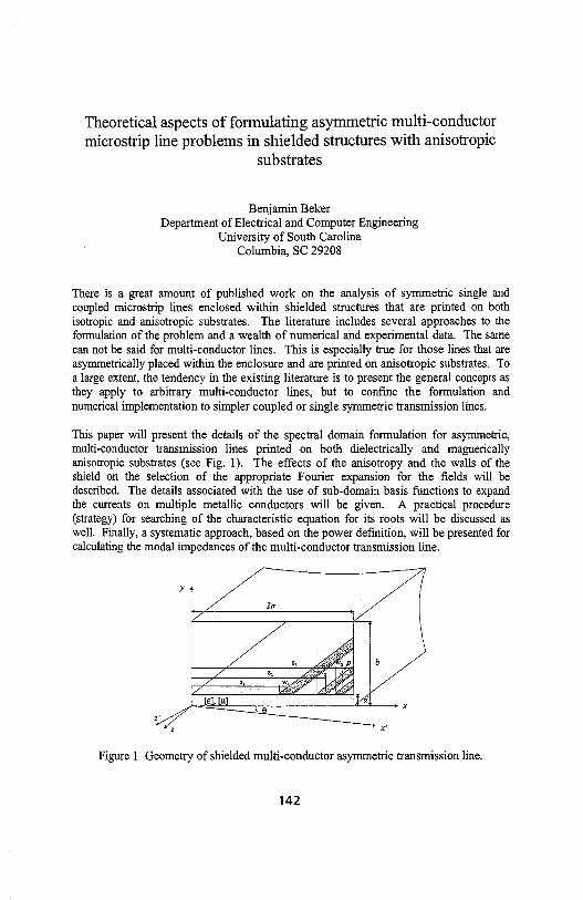
Theoretical aspects of formulating asymmetric multi-conductor microstrip line problems in shielded structures with anisotropic
substrates
Benjamin Beker Department of Electrical and Computer Engineering
University of South Carolina Columbia, SC 29208
There is a great amount of published work on the analysis of symmetric single and coupled microstrip lines enclosed within shielded structures that are printed on both isotropic and anisotropic substrates. The literature includes several approaches to the formulation of the problem and a wealth of numerical and experimental data. The same can not be said for multi-conductor lines. This is especially true for those lines that are asymmetrically placed within the enclosure and are printed on anisotropic substrates. To a large extent, the tendency in the existing literature is to present the general concepts as they apply to arbitrary multi-conductor lines, but to confine the formulation and numerical implementation to simpler coupled or single symmetric transmission lines.
This paper will present the details of the spectral domain formulation for asymmetric, multi-conductor transmission lines printed on both dielectrically and magnerically anisotropic substrates (see Fig. 1). The effects of the anisotropy and the walls of the shield on the selection of the appropriate Fourier expansion for the fields will be described. The details associated with the use of sub-domain basis functions to expand the currents on multiple metallic conductors will be given. A practical procedure (strategy) for searching of the characteristic equation for its roots will be discussed as well. Finally, a systematic approach, based on the power definition, will be presented for calculating the modal impedances of the multi-conductor transmission line.
y
2a
z' x'
Figure 1 Geometry of shielded multi-conductor asymmetric transmission line.
142

Optimizing Directivity of a Phase Velocity Compensation "Wiggly" Coupler
Christina Lumbreras, Denchai Worasawate*, Douglas Huang
The directivity of loosely coupled microstrip couplers decreases as the frequency
increases. This problem associated with parallel-coupled lines is attributed to the velocities of the
odd- and even-modes, which propagate at unequal speeds. The difference between modal
velocities can be resolved by several techniques. Podell first introduced the idea of wiggling the
parallel-coupled lines in a saw tooth manner so that the odd-mode is slowed in such a way that its
velocity can equal that of the even mode. Ideally, the even mode is unaffected by the wiggling
section. This technique is a simple planar technique with no additional processing beyond the
normal printing and etching of the microstrip coupler.
Uysal has derived the design equations for the optimum dimensions of the wiggly
coupler. The derivation relies on calculation of even- and odd-mode fringing and gap
capacitances and effective dielectric constants (rr, and Efro ). As compared to numerous
simulations, we have shown numerically that the design equations do not give us an optimum
value. Even- and odd-mode velocities 01 and V0 ) are still unequal.
We have desigied the optimum values for a 20 dB wiggly coupler using an
electromagnetic field solver, Sonnet. In each simulation, the dimensions (width, L, and depth, d,
as shown in Figure 1.) of the "wiggle" were varied to maximize directivity. The optimum
geometry is determined by the values with the smallest percent difference between even- and
odd-mode velocities. The results using these methods mirror measured results of manufactured
prototype wiggly couplers.
Figure 1. The dimensions of saw-toothed wiggle
143

Network Analysis and Design of a Slot-Coupled Microstrip Directional Coupler
Jeong Phill Kim*, Se Chang Ohl, and Wee Sang Park!
• LG Precision Co., Korea Department of Electronic and Electrical Engineering, Microwave Application Research Center
Pohang University of Science and Technology, Korea
Slot-coupled back-to-back microstrip lines have been increasingly used as a coupling structure in a monolithic microwave integrated circuits. The examples include back-to-back microstrip/microstrip transition, out-of-phase power divider, directional coupler, and feed network of an active phased-array antenna, etc. Among them, directional coupler has been designed with multi-slot coupling structures by applying the optimization process with the data obtained from the numerical analysis(w. Schwab and w. Menzel, 1994 IEEE
MTT-5 Di9est pp. 897-898.). Even though numerical methods have been widely undertaken to analyze the slotcoupled microstrip circuits, these approaches do not provide conceptual insight into the circuit for efficient design and synthesis.
In this paper, network analysis(J. P. Kim and w. s. Park, IEEE MTT-46, pp. 1484-1491, Oct. 1998.) is used in the design of the directional coupler. An equivalent network for the slot-coupled microstrip circuit is developed, and related network parameters are determined. The characteristics of the directional coupler can then be obtained from the even and odd-mode analysis. The electrical distance between the slots ( 11) and normalized series slot reactance (x) are determined from the required coupling amount (C = jS31 j2). The required xis attained by choosing the length, offset distance, and inclination angle of the slot. A broadband directivity is also achieved by using a multi-slot structure of non-uniform length. For a directional coupler with two slots, the design equations are given as
1 11 = 2cos-1 (2 C-1), d - 1
an x = tan/1'
It is known from these equations that when 11 = rr/4 and x = 1, the coupler becomes a 3 dB quad-hybrid.
In order to show the validity of the design, a 3 dB quad-hybrid operating at f = 2 GHz was fabricated and tested. Two identical slots are placed 13.63 mm apart in the common ground between the two microstrip lines. The length and width of the slot are 27.14 mm and 1.10 mm, respectively, and the width of microstrip line is 2.54 mm. The thickness and dielectric constant of two identical substrates are 31 mils and 2.2, respectively. The computed characteristics of the quad-hybrid are shown in Fig. 1. 1 dB bandwidth of coupling is about 10 In this frequency band, directivity is larger than 15 dB and quadrature phase deviation is less than 2° which shows a good phase quadrature. The measured results agree well with the computed, indicating the validity of the proposed efficient design methodology.
so 180 I I I I I I
iii' - measurement - - - measurement ,,::. ~ - - - - · computation -
I - · · · computation a I :s
!i I -- / ; 90
ti i g, ; I '§. 8
·SO 1.5 2 2.5 1.5 2.5
frequency (GHz) frequency (GHz)
Fig. 1 Measured and computed results of the designed 3 dB hybrid.
144

Study of the Moat Effect on Split Ground Planes
Cheng-Nan Chiu Computer and Communications Research Laboratories Industry Technology Research Institute, Taiwan, ROC
Splitting the ground planes in PCB systems is an important method to prevent the EMI into the surroundings, to enhance the immunity of the sensitive areas, and also to reduce the noise coupling among the functional differently parts. Besides, this method is used for multiple power sources to distribute (H-J. Liaw and H. Merkelo, IEEE Circuits & Devices, 22-26, 1997). Nowadays, this method is already exhaustively used in the modem high-speed, mixed-signal, and RF PCB EMC design. For the purpose of isolation, the split ground planes are separated by the etched moat such as that in Fig. 1. As the signal trace crosses over the moat, the signal current loop is broken by the moat and then large amount of radiation will be excited as well as the signal integrity will be degraded. In this study, several practical structures are modeled and simulated to investigate the moat effect by using a 3D, full wave, method of moment simulator.
Building a bridge under the signal trace and using the balance-type signal traces are two useful solutions to overcome the difficulty of signal traces crossing over the moats. Both solutions are investigated in detail. Because too many bridges on the moat will make worse the isolation performance of the split ground planes, sharing a common bridge for different signal traces may not be avoided in practical PCB design. As a consequence, the increasing ofcrosstalk and degrading of transmission performance are inevitable. Based on the analysis of simulation results, the study gives useful suggestions for this trade-off in actual PCB design.
moat signal trace
l _,/ '/ ---='S=--J 1 /?06?. 1 r ,,,~
split ground planes
Fig. 1 Typical configuration of the moat on split ground planes
145

Decoupling Capacitance Effect Both on the Signal Integrity and EMI for High-Speed PCB Circuits
Shie-Chie Chao Central Research Institute, Tatung Co., Taipei, Taiwan, R.O.C.
Tzong-Lin Wu* Department of Electrical Engineering,
National Sun Yat-sen University, Kaohsiung, Taiwan, R.O.C. E-mail: [email protected]
Summary To comply with the FCC regulation of part 15 for the radiated emission of digital
electronic products, shunting a decoupling capacitance on the critical traces for high frequency signal is a common approach to reduce the radiated emission.
In this work, a receiving logic gate is drive by a high-speed logic gate with short rising and falling edge through a signal trace in microstrip structure. Based on the IBIS (1/0 Buffer Interface Specification) model of these two gates and the transmission line model of the trace, the signal quality on the trace with decoupling capacitance being shunted at the driving end is simulated in time domain. Based on the experimental measurement in fully anechoic chamber with 3m-measurement distance, the decoupling capacitance effects on the radiated emission of the high-speed digital signal on PCB are investigated. It has been found statistically that the bypass capacitance can not reduce the radiated emission for the low frequency signal and has no more that 3dB improvement for the radiated emission with the frequency higher than 300Mhz. We have also seen that the bypass capacitance will cause signal ringing and destroy the signal quality.
In conclusion, the common approach of shunting the decoupling capacitance is not so tricky for reducing the EMI of high-speed clock circuits and will cause signal integrity problem.
146

Tuesday Afternoon URSI B Session 45 Japanero
REMOTE SENSING Session Chaiis: G. Brown and A. Nashashibi Page
1: 15 Opening Remarks
1 :20 'IE/fM simulation of interferomeuic measurements, B. Houshmand, Jet 148 Propulsion Laboratories, USA
1:40 MMW measurements of the extinction and volume backscattering coefficients of 149 trees, P. Frantzis*, F. Ulaby, A. Nashashibi, University of Michigan, USA
2:00 MMW polarimetric observations of surfaces and shon vegetation at near-grazing 150 incidence, A. Nashashibi*, P. Frantzis, F. Ulaby, Univeisity of Michigan, USA
2:20 The modulation of the brighmess temperature by ocean surface waves, D. Kasilingam, 151 Univeisity of Massachusetts, Dartmouth, USA
2:40 IFSAR simulation using the shooting and bouncing ray technique, R. Bhalla*, H. 152 Ling, University of Texas at Austin, USA, B. Houshmand, Jet Propulsion Laboratory, USA
147

TE/TM Simulation of Interferometric Measurements
Bijan Houshmand Jet Propulsion Laboratory
California Institute of technology 4800 Oak Grove Drive
Pasadena, CA 91109-8099 [email protected]
. Interferometric synthetic aperture radar (IFSAR) measurements at X-, C-, L-, and P-band
are used to derive ground topography at meter level resolution. Interpretation of the
derived topography requires attention due to the complex interaction of the radar signal with
ground cover. The presence of penetrable surfaces such as vegetation, and tree canopies
poses a challenge since the depth of penetration depends on a number of parameters such as
the operating radar frequency, polarization, incident angle, as well as terrain structure. The
dependence of the reconstructed topography on polarization may lead to the characterization
of the ground cover. Simulation of interferometric measurements is useful for
interpretation of the derived topography (B. Houshmand, Proceedings of URSI, 314,
1997). In this talk, time domain simulations for interferometric measurement for TE- and
TM- polarization are presented. Time domain simulation includes the effects of the surface
material property as well geometry comparable the radar signal wavelength (B.
Houshmand, Proceedings of the URS!, 25, 1998). The IFSAR simulation is carried out
in two steps. First, the forward scattering data is generated based on full wave analysis.
Next, the electromagnetic information is inverted to generate surface topography. This
inversion is based on the well known IFSAR processing technique which is composed of
signal compression, and formation of an interferogram. The full wave forward scattering
data is generated by the scattered-field formulation of the FDTD algorithm. The simulation
is carried out by exciting the computational domain by a radar signal. The scattered field is
then computed and translated to the receiving interferometric antennas using the time
domain Huygen's principle. The inversion process starts by compressing the time-domain
data. The range compressed data from both receivers are then coregistered to form an
interferogram. The resulting interferogram is then related to the ground topography using
the radar imaging geometry. In this talk, the simulation results are compared with the C
hand TM IFSAR derived topography, and the TEffM SAR images at L-Band.
148

MMW Measurements of the Extinction and Volume Backscattering Coefficients of Trees
Panayiotis Frantzis*, Fawwaz T. Ulaby, and Adib Nashashibi Radiation Laboratory
Department of Electrical Engineering and Computer Science The University of Michigan, Ann Arbor, MI 48109-2122
Tel:(734) 764-0501, Fax:(734) 647-2106 Email: [email protected]
Abstract
At millimeter wavelengths, it is very difficult to characterize the shapes of leaves and branches at a scale commensurate with the wavelength, and it is practically impossible to perform a vector radiative transfer model calculation using numerical techniques. Hence, in order to study and relate the backscatter to the physical parameters of a tree canopy, we use an alternative approach in which the structure of radiative transfer theory is retained, but we supply the volume backscattering and extinction properties of the canopy medium by directly measuring them with a mobile scatterometer. The scatterometer is fully polarimetric and operates at 35 and 95 GHz. Using this technique, measurements were performed for 17 different types of trees at 35 GHz and for 22 different types at 95 GHz. Both sets included deciduous and coniferous trees and in some cases, the measurements were conducted for several different tree conditions (foliated versus defoliated). The scatterometer measurements and the ground truth data were used to develop a model for cr0 which accounts for its variability in terms of the propagation parameters of the trees. Both the extinction and volume backscattering coefficients were estimated and compared with corresponding values from previous studies. It was observed that the extinction coefficient increases for both denser trees and higher frequencies (35GHz versus 95 GHz). The number ofleaves or fruits/cones, and the structure of the tree play a major role in the difference of the extinction and volume backscattering coefficients between trees. This paper provides a summary of the measurements and how they relate to the physical properties of the tree canopies.
149

MMW Polarimetric Observations of Surfaces and Short Vegetation at Near-Grazing Incidence
Adib N ashashibi*, Panayiotis Frantzis, and Fawwaz T. Ula by The University of Michigan
3228 EECS, 1301 Beal ave., Ann Arbor, MI 48109-2122 Tel: (734) 764-1091, Fax: (734) 647-2106
Email: [email protected]
"\il/ith recent advancements in solid-state technology, reliable millimeter-wave (MMW) components have become avialable, leading to a renewed interest in MMW radars for a wide range of remote sensing applications. Because of the compactness and high resolution of MMW radars, they have become the primary sensors in certain applications related to detection and tracking of manmade targets in the presence of clutter. Nevertheless, the study of MMW interactions with natural terrain is still at its initial stages. For example, several of the proposed applications, such vehicle collision avoidance, require an accurate characterization of the MMW backscatter response of clutter at near grazing incidence. Yet, MMW measured data of clutter, in general, at near grazing incidence are practically nonexistant.
In this paper, we will present the results of a recent measurement campaign aimed at characterizing the polarimetric radar backscatter response of bare surfaces and short vegetation, such as grass, soybean, and corn fields at 35 and 95 GHz. During this campaign, measurements were conducted repeatedly over several months and were backed up by an extensive collection of ground truth data. In particular, the backscattering coefficients (aiv, ahh> and aih) and the statistics of the phase difference between the co-polarized elements of the scattering matrix will be examined as a function of both the radar parameters (frequency and incidence angle) and the physical parameters of clutter (i.e., moisture content, number density, etc.). For example, it is observed that the backscattering coefficients of bare surfaces and short vegetation, at near grazing incidence, were higher in magnitude at 95 GHz when compared to 35 GHz. Furthermore, they exhibited a strong dependence on moisture. Additional observations regarding the dynamic range of the measured response and its sensitivity to variations in the physical parameters of clutter will be presented. The conclusions drawn from the presented data will serve as a guide for interested parties in the scientific community towards the development of theoretical and/ or empirical models that characterize the backscatter response of these types of clutter and towards the development of optimal detection algorithms.
150

The Modulation of the Brightness Temperature by Ocean Surface Waves
Daya/an Kasilingam Department of Electrical & Computer Engineering
University of Massachusetts, Dartmouth North Dartmouth, M4 02747
Tel - (508) 999-8534 FAX - (508) 999-8489 e-mail - [email protected]
Introduction
The brightness temperature is used as a measure of the microwave emissions from a surface or an object. It is defined as the product of the emissivity and the physical temperature of the surface. The emissivity is a function of the surface roughness and the dielectric properties of the surface. In the ocean, the surface roughness is primarily dependent on the surface waves, which in turn are a function of the local wind conditions. Thus by measuring the brightness temperature of the ocean surface, one may estimate the near-surface wind vector. Knowledge of the distribution of the nearsurface wind vector is imperative for understanding various air-sea interaction processes in meteorology and oceanography. Understanding the relationship between the brightness temperature and the wind vector requires the capability to model the microwave emissions from the ocean surface. This requires a fast and accurate technique to estimate the brightness temperature over a variety of viewing conditions.
Theory
The emissivity of the ocean surface in a given polarization, i, is given by
&; = 1- 4~ sec 8, ff [u;h(~.e.,¢,)+ujy(8;,8,,¢,)]dQ,, n,
where 8;,8,,and¢, are the incident angle, elevation and azimuth angles of the scattering
direction, respectively. ds are the bistatic scattering coefficients. The integration is performed over all scattering angles. To calculate the emissivity, the bistatic scattering coefficients need to be calculated for all scattering angles. In standard modeling techniques this is an extremely tedious process. In this paper, simulations of the Exact Expansion Linear Algorithm Method (EELAM) is used to study the relationship between the brightness temperature and ocean surface waves.
The EELAM model calculates the bistatic scattering for all incidence and scattering angles. Furthermore, the model eliminates the need for calculating the non-propagating, stationary fields around the ocean surface. This allows one to represent the scattered fields in terms of a finite series of propagating modes instead of a truncated set of an infinite series. The use of the finite set improves the efficiency and also the accuracy of the scattering calculations.
Results
The simulations show that • the brightness temperature of the ocean surface in the vertical polarization increases with
wind speed for small and moderate incidence angles, but decreases with wind speed for large incidence angles,
• the brightness temperature of the ocean surface in the horizontal polarization increase with wind for all incidence angles, with the sensitivity being greater at the larger incidence angles,
• the directional dependence of the brightness temperature in the vertical polarization has a 180° ambiguity and
• the directional dependence of the brightness temperature in the horizontal polarization has less of an ambiguity and may be used to resolve the ambiguity.
151

IFSAR Simulation using the Shooting and Bouncing Ray Technique
Rajan Bhalla*, Hao Ling and Bijan Houshmand+
Department of Electrical and Computer Engineering The University of Texas at Austin
Austin, TX 78712 U.S.A
+Jet Propulsion Laboratory California Institute of technology
4800 Oak Grove Drive Pasadena, CA 91109-8099 U.S.A.
Interferometric Synthetic Aperture Radar (IFSAR) is a technique that allows an automated way to carry out terrain mapping. IFSAR is carried by first generating a SAR image pair from two antennas that are spatially separated. The phase difference between the SAR image pair is proportional to the topography. After registering the SAR images, the difference in phase in each pixel is extracted to generate an interferogram. Since the phase can only be measured within 21t radians, phase unwrapping is carried out to extract the absolute phase for each pixel that will be proportional the local height. While IFSAR algorithm is typically applied to measurement data, it is useful to develop an IFSAR simulator to develop a better understanding of the IFSAR technique. A 2-D IFSAR simulator based on geometrical optics has been used to evaluate the effects of multibounce and layover effects (Houshmand, URSI Radio Science Meeting, July 1996). The IFSAR simulator can be used in choosing system parameters, experimenting with processing procedures and mission planning. In this paper we will present an 3-D IFSAR simulation methodology to simulate the interferogram based on the shooting and bouncing ray (SBR) technique.
SBR is a standard ray-tracing technique used to simulate scattering from large, complex targets (Ling, Chou and Lee, IEEE Trans. Antennas Propagat., Feb. 1989). SBR is carried out by shooting rays at the target or scene. At the exit point of each ray, a raytube integration is done to find its contribution to the total field. A fast algorithm has been developed for the SBR for simulating SAR images of complex targets (Bhalla and Ling, IEEE Trans. Antennas Propagat., July 1993). In the IFSAR simulation, we build upon the fast SAR simulation technique. Given the antenna pair configuration, radar system parameters and the geometrical description of the scene, we first simulate two SAR images from each antenna. After post processing the two SAR images, we generate an interferogram. Phase unwrapping is then performed on the interferogram to arrive at the desired terrain map.
We will present results from the SBR-based IFSAR simulator. The results will include terrain map reconstruction of urban environments. The reconstruction will be compared to the ground truth to examine the fidelity of the simulation. We will also investigate the effect of multi-bounce scattering in urban environments on phase unwrapping and reconstruction.
152

Tuesday Afternoon ORSI B Session 46 Koi
RANDOM SURFACES Session Chaiis: A. Ishimaru and J. Johnson Page
1:15 Opening Remarks
I :20 A novel spectral acceleration algorithm for the computation of scattering from two- 154 dimensional rough surfaces with the forward-backward method, D. Torrungrueng*, Ohio State University, USA, H. Chou, Yuan Ze Univeisity, Taiwan, J. Johnson, Ohio State Univeisity, USA
1:40 Further results in diffraction by a randomly rough knife edge, B. Davis*, G. Brown, 155 Virginia Polytechnic Institute and State University, USA
2:00 Scattering by a planar metal surface with randomized rectangular grooves, M. 15 6 Morgan*, Naval Postgraduate School, USA, F. Schwering, NJ, USA
2:20 Third order small perturbation method for dielectric rough surfaces, J. Johnson, Ohio 157 State Univeisity, USA
2:40 Localized and enhanced electromagnetic fields in the random waveguide, K. Tanaka, 158 M. Tanaka, Gifu Univeisity, Japan
153

A Novel Spectral Acceleration Algorithm for the Computation of Scattering from Two-Dimensional Rough Surfaces with the Forward-Backward Method
D. Torrungrueng*1, H.-T. Chou2 and J.T. Johnson1
1 Ohio State University Dept. of Electrical Engineering ElectroScience Lab Columbus OH 43212 Tel: (614)292-7981 Fax: ( 614) 292-7297 [email protected] [email protected]
2 Yuan Ze University Dept. of Electrical Engineering Chung-Li, Taiwan Tel: 886-3-463-8800 Fax: 886-3-463-9355 [email protected]
The forward-backward method with a novel spectral acceleration algorithm (FB/NSA) has been shown to be a very efficient iterative method of moments for the computation of scattering from one-dimensional perfectly conducting and impedance rough surfaces (H.-T. Chou and J. T. Johnson, Radio Sci.,33, 1277-1287, 1998). The NSA algorithm is employed to rapidly compute interactions between widely separated points in the conventional FB method, and is based on a spectral domain representation of source currents and the associated Green's function. For fixed surface roughness statistics, the computational cost and memory storage of the FB/NSA method is O(N) as the surface size increases. This makes studies of scattering from large surface, as are required in low-grazing-angle scattering problems, tractable.
This paper will illustrate the FB/NSA method for the computation of scattering from two-dimensional (2D) rough surfaces. The NSA algorithm for this case involves a double angular spectral integral representation of source currents and the three-dimensional free space Green's function. The coupling between two angular spectral variables makes the problem more challenging. In addition, three separated spectral expasions are required for the weak interaction computations of widely separated points in order to make the FB/NSA method efficient. It can be shown that the computational efficiency of the FB/NSA method for 2D rough surfaces remains O(N) as one of the surface size increases. Comparisons of numerical results between the FB/NSA method and the banded matrix iterative approach with a canonical grid expansion (BMIA/CAG) show that for very rough surfaces the FB/NSA method can be more efficient than BMIA/CAG.
154

Further Results in Diffraction by a Randomly Rough Knife Edge
Bradley A. Davis* and Gary S. Brown ElectroMagnetic Interactions Laboratory
Bradley Department of Electrical Engineering Virginia Polytechnic Institute & State University
Blacksburg, VA 24060-0111
In many propagation studies, the estimation of the effect of path-obstructing ridges, mountains, and other natural obstacles in long range conununication links is simulated using a knife edge obstruction. The use of this approximation is now of particular interest in assessing blockage effects involving much shorter paths, e.g., such as in propagation in an urban environment where buildings and other man-made obstacles cause the path blockage. A particularly useful solution to the diffraction by a knife edge boundary has been developed by Prof. R.E. Collin, in his book Antennas and Radiowave Propagation. In this work, he gives a relatively simple and understandable development of the problem that allows field predictions along the line-of-sight path in both the Fresnel and far zones.
In a previous presentation, the authors have used Prof. Collin's result to address the effects of edge roughness on the diffraction pattern (APS-URSI Symposium, Atlanta, GA 1998) as this is a major uncertainty in applying the results to real situations. As an extension to this work, the paraxial approximation inherent to the original work will be relaxed in order to provide an estimate of the diffraction field in regions removed from the line-of-sight path. Although this extension adds complexity to the relatively simple solution previously presented, it is necessary when considering conununication links in which the coverage pattern beyond an obstacle is to be predicted. In addition to these results, preliminary efforts that include the roughness effects on pulse propagation past a rough knife edge will be discussed.
The roughness on the knife edge boundary is assumed to comprise a non-zero mean second order process with jointly Gaussian roughness and a Gaussian spectrum. The latter is used for demonstration purposes and the theory is not limited to this particular spectral form. This presentation will focus not only on the development of the new results but also on the most important parameters effecting the diffraction field. These include the distances of the transmitter and receiver from the knife edge, the degree of path blockage present, the edge roughness, and the antenna pattern of the transmitter. Numerical calculations demonstrate the interplay of these parameters and illustrate the effect of the roughness relative to an edge-free path.
155

SCATTERING BY A PLANAR METAL SURFACE WITH RANDOMIZED RECTANGULAR GROOVES
lvfichael.A. Morgan* ECE Department, Naval Postgraduate School 833 Dyer Road, Monterey, C.A 93943-512 l
Felix K. Schwering .ATIN: .AMSEL-RD-ST-WL
Fort Monmouth, NJ 07703-5202
Scattering by stochastically rough surfaces has been investigated for several decades. Computational methods include physical and geometrical optics approximations, integral and differential equation based solutions, and formulations using parametric distributions for geometric and material properties.
A parametric approach to constrained random surface scattering is formulated by way of a modal expansion solution involving a single rectangular groove in a metal ground plane filled with dielectric material (M . .A. Morgan and F.K. Schwering, Electromagnetic Waves, PIER 18, 1998, 1-16). Variation on the single groove case is employed to efficiently consider the case of multiple grooves with randomized locations, dimensions and materials. Statistical expectations for scattered fields and radar cross section are performed in a multi-dimensional parameter space. Two of the integrations are performed analytically while numerical evaluations are required for the remaining parameter dimensions. The computational procedure is applied to special case examples illustrating wideband enhancement of backscattering.
156

Third Order Small Perturbation Method
for Dielectric Rough Surfaces
J. T. Johnson
Department of Electrical Engineering and ElectroScience Laboratory
The Ohio State University
205 Dreese Laboratories, 2015 Neil Ave, Columbus, OH 43210
(614) 292-1593, (614) 292-7297 FAX, email: [email protected]
The small perturbation method (SPM) for rough surface scattering, originally
derived by Rice (S. 0. Rice, Commun. Pure Appl. Math, 4, 361-378, 1951), has been extensively applied to problems in remote sensing and propagation. Typical
uses of the theory involve only the first order field terms in surface height, which
provide the first predictions of incoherent scatter from a rough surface. Field results
up to second order were presented in the original paper, but evaluation of second
order terms requires a numerical integration which if often too time consuming for many applications. The exception is the second order correction to the specular
reflection coefficient, which has been applied in many references. A consideration
of scattered power shows that an expansion of fields up to first order along with the second order reflection coefficient correction is sufficient to obtain all scattered
power terms up to second order in surface height, so the second order SPM has also
been used to study thermal emission from rough surfaces.
In this paper, third order field terms in surface height are presented and their application to scattering and emission problems considered. Third order field terms have previously not been presented due to the complexity of the formulation, which
becomes increasingly tedious as higher order terms are considered. However, a
systematic formulation of the SPM equations relieves some of the difficulty of the
derivation and enables third order terms to be obtained. The original method of Rice, in which the Rayleigh hypothesis is applied to scattering from a periodic surface, is used, and non-periodic surface results are obtained in the limit of infinite
surface periods. Third order field results are of particular interest in the emisison problem, because they contribute to the first prediction of an upwind/downwind
brightness temperature asymmetry for non-Gaussian process ocean surfaces. It is
shown that third order terms require an four-fold integration over the surface bis
pectrum, and therefore remain computationally intensive, but still provide useful information on properties of scattering and emission from rough surfaces.
157

Localized and Fnhanced Electromagnetic Fields in fue Randan Waveguide
Komo TanakaandMasahiro Tanaka
DepartmentofEkctronicsandCompuJer Engineering, Gifu Universily, Yanagida 1-1, Japan501-l 193, Fax: +81-58-230-1895, E-Mail: [email protected]{o.gifu-u.acjp
The localizatioo of eleclromagnetic waves in rardom media is an interesting problem from theoretical and pra:tical view points and have been extemively investigallld so far. In this paper, the elearomagnetic propagatioo in a waveguide with irregular-shaped metll walls has been investigated in detail and it is found that the electromagnetic wave can be strongly localized and its strength can be slrong!y enhm:ed in a small regioo in the waveguide un1er specific conditions.
Geometry of the problem considered in this paper can be stated as follows: A Twodmensiooal waveguide with irregular-shaped melal walls (ramom waveguide) is samwiched by two straight waveguides. It is as&JIDed that both straight waveguides satisfy the single-mode romition and the spa;:e in ea::l! waveguide is a vacuum. A 'IE dominant-mode is aS5UIIlfd to be incident from the left straight waveguide to the waveguide with irregular-shaped walls. The incident 'IE-mode is reflected to the left waveguide and tranmtll:d to the right waveguide. It is possible to solve this problem numerically with high aa:uracy by the boumaiy-element metlxxl (BEM) ba<ln oo Guided-Mode Extra;red Integral F.quations (GMEIE's). The reflecred guided-mode, trarumitted guided-mode and field distributioo in the waveguides can be obtained mnnerically. Shapes of the irregular walls of the ramorn waveguide have been created by the surnrnatioo of~ shot-pluses. So, the auto-<Xnelation functioo of random wall-positions is given by Gaussian, using OntJ,bell's treory. ~ used in the nwnerical calculations are given by follows: width of
Slraight waveguide is 0.995Xwavelength, length of randan W8Neguide is 3631 X wavelength, correlatioo length of the wall is0.64Xwavelength. The GMEIB's of the problem have been solved by the convenlional BEM (manent methcd) wlJ:re quadratic fuooioo as basis functioo and delta functioo as testing function were used. It has been oonfirmed that all nwnerical results in this paper satisfy the energy conservalioo law within an aa:uracy of 1 % and fairly saiisfy the reciprocity relatiOIL
The dqlendenc:e of the power ttan&nission coefficient on the amplitude of rarxlorn wall is investigaled in detail for given SIOChastic Poisson processe.s. It is found that th:re are several = romitions which give small or large tranwissiom. It is also found that the electranagnetic wave is strongly localizro and its field is slrong!y enhm:ed in the small region in the random waveguide at several =iaoce conditions. Fer example, we can furl that the eleclric field can become about 100 times larger dlan that of the imdent wave wxler a resonarre romitim Furthenncre, it is foum that large cwrent distributions exist oo the wall in the vicinity of localizro and enhm:ed fields. We have investigated three types of rarxlan waveguides and can always furl conditions which give strong localization and Jargeenh31X:ementin these examples. So, the !hes:: characteristics are general prqierties of randan waveguide.
This inleresting plx:nanenon can be applied to practical problem such as enhancemi:nt of electric field in using the oonlinear mediwn and may explain some natural plroomena. Many queslions concerning pcstioos of the localized and enhm:ed fields in the rarxlan waveguide remains. It is inleresting problem what is the essential parameter which affects the rnaxirnwn value of the enhanced field. It is not diffiatlt to prove the alx>ve-rnentiooed phenornenoo experimentally.
158

Tuesday Afternoon URSI B SPECIAL SESSION Session 48 Convention Center Ballroom II
APPLIED MATHEMATICS IN ELECTROMAGNETICS · Il A MEMORIAL SESSION HONORING PROFESSOR RALPH E. KLEINMAN Session Chairs: T. Angell and D. Dudley
1:15 OpeningRemarks-T. Angell, University of Delaware, USA
Page
1:20 On a null-placement problem in the mathematical theory of optimal antennas, T. 160 Angell, University of Delaware, USA, A. Kirsch, University of Karlsruhe, Germany
1 :40 A preconditioning procedure for the EFIE, R. Adams*, G. Brown, Virginia 161 Polytechnic Institute and State University, USA
2:00 Aspects of analytic methods to determine the current distribution of a circular loop 162 antenna, E. Lepelaars, TNO Physics and Electronics Laboratory, The Netherlands
2:20 Review of low-frequency scattering from two-dimensional perfect conductors, A. 163 Yaghjian, Hanscom AFB, USA
2:40 Exact electromagnetic penetration through a gap in a comer, P. Uslenghi, University 164 of Illinois at Chicago, USA
3:00 Break
3:20 Inverse scattering and specialized modified gradient methods, B. Duchene*, D. 165 Lesselier, Signals and Systems Laboratory, France
3:40 Basis properties of traces and normal derivatives of classical spherical-wave 166 functions, A. Dallas, University of Delaware, USA
4:00 Simultaneous inversion of contrast sources and contrast, P. van den Berg, Delft 167 University of Technology, The Netherlands
4:20 Closing Remarks - D. Dudley, University of Arizona, USA
159

Bl.l Antenna Analysis & Design
On a Null-Placement Problem in the Mathematical Theory of Optimal Antennas
T. S. Angell Center for the Mathematics of Waves Department of Mathematical Sciences
University of Delaware Newark, Delaware 19716, U.S.A.
and
A. Kirsch Mathematisches Institut II
Universitii.t Karlsruhe D-76128 Karlsruhe, Germany
Abstract
In line with work that the authors and Ralph Kleinman pursued for a number of years, we discuss here problems of optimization of various figures of merit for radiated far-field patterns of conformal antennas. Our approach is to use methods of functional analysis, systematically, to analyze some general class of antenna optimization problem, and to use the general analysis, and then to carry out computations for specific configurations (see T. S. Angell, A. Kirsch, and R. E. Kleinman, Proc. IEEE, 79, 1559-1568, 1991).
We consider a class of radiation problems and attempt to determine the current distribution on the antenna which optimizes some desired property of the far field. In the reference cited above, we have shown that both traditional problems of antenna synthesis, as well as problems of optimizing, for example, the gain of an antenna, subject to appropriate constraints on the boundary conditions, may be formulated in this context.
Our discussion will concentrate on a problem which is related to adaptive control of far-field patterns, the so-called null placement problem, which arises in problems of telecommunications, radio astronomy, as well as in situations where jamming signals are present. Specifically, we ask for an input which maintains as closely as possible a desired far field pattern while minimizing the far field in the direction of the interfering signal.
The discussion includes the development of necessary conditions for a an optimizing input in the form of a Lagrange multiplier rule in a general context. The problem is then specialized to the case of a circular loop and the necessary conditions applied to show that the it is possible to actually compute the inputs appropriate for the adaptive nulling either in the side lobe portion of the far field or in sectors overlapping the main beam.
In addition, we indicate how similar problems involving additional figures of merit, may be approached using vector optimization techniques to find "trade-off" surfaces so that, for example, one may discuss an adaptive nulling method in the case in which the nominal pattern is one which optimizes one or more other performance measures.
160

A Preconditioning Procedure for the EFIE
R. J. Adams* and G. S. Brown ElectroMagnetic Interactions Laboratory
Virginia Polytechnic Institute & State University Blacksburg, VA 24061-0111
A well-known problem in the numerical simulation of time-harmonic electromagnetic scattering problems is the low frequency breakdown problem associated with the EFIE. This breakdown occurs because the condition number of the EFIE increases with the total number of unknowns per wavelength. The conditioning of the MFIE, however, does not change as the discretization interval tends towards zero. Unfortunately, not all problems can be formulated using the MFIE and it is sometimes necessary to work with the EFIE.
The significantly different properties of the EFIE and MFIE formulations of the same scattering problem are illustrated by considering the problem of scattering from an infinite flat surface. The MFIE propagator for this problem is identically zero and the Born term of the MFIE provides the exact solution to the scattering problem. This property of the MFIE is often interpreted as corresponding to the physical fact that there are no multiple scattering interactions for this geometry. In contrast to the behavior of the MFIE, the EFIE kernel is nonzero and singular. Thus, even for the flat surface geometry for which there are no multiple scattering interactions, the EFIE indicates a coupling between the equivalent surface currents. This coupling arises because the EFIE provides a boundary condition on the electric field in terms of magnetic field sources. It is this fact which causes the EFIE to become poorly conditioned as the frequency approaches zero.
In this presentation we demonstrate that this problem can be remedied using a preconditioning procedure that renders the EFIE well-conditioned for an arbitrarily smalldiscretization interval. This preconditioning procedure follows from a consideration of the integral equations satisfied by the incident and total fields on the surface of a scatterer. This consideration leads directly to an integral identity that relates the EFIE and MFIE kernels. The resultant identity defines a preconditioning procedure that renders the EFIE stable with respect to the discretization interval. Although this relationship is derived from well-known integral relationships satisfied by the incident and total fields, it apparently has not been previously used to remedy the low-frequency breakdown problem associated with the EFIE.
Numerical calculations verifying these theoretical predictions will be provided. The incorporation of this preconditioning procedure with methods aimed at reducing the iteration count for the solution of a moment method formulation of time-harmonic scattering problems will alsobe discussed.
161

Aspects of analytic methods to determine the current
distribution of a circular loop antenna
E.S.A.M. Lepelaars, TNO Physics and Electronics Laboratory,
Section Electromagnetic Effects, P.O. Box 96864, 2509 JG The Hague,
The Netherlands, Phone: +31-70-3740356, Fax: +31-70-3740653,
e-mail: [email protected]
The problem of determining the current distribution along a circular thin wire is a fun
damental and classical problem in electromagnetic theory. Computing the electric current,
which is either generated by an incident field or impressed by a voltage pulse in a small gap,
is the first step to computing the induced electromagnetic field. For a slow voltage pulse, a
uniform current distribution may be assumed. However, in the case that the voltage pulse
contains short wavelengths in comparison with the loop's circumference, this assumption is
no longer realistic. A better approach then is to use thin-wire approximations and to consider
the integral equation for the total current that flows along the surface of a perfectly conduct
ing thin wire. These approximations, first applied by Pocklington for straight and circular
thin wires, replace the two-dimensional boundary integral equation for the current density
on the surface of the wire by a one-dimensional integral equation for the total current along
the wire. For this total current, the observation point can be chosen either on the surface
of the wire or on the central axis. In the latter case, the kernel remains bounded, which
allows us to devise a more stable algorithm. Starting from the Pocklington-type equation,
there are several ways to compute the current distribution. One way is to use a Green's
function technique to invert the wave operator. This method, first applied by Hallen, results
in an alternative integral equation in which the kernel doesn't need to be differentiated. This
limits the strongly varying behavior of the kernel which is a main advantage for numerical
evaluation. Another way is to use series expansions with respect to angle or frequency. The
current is then represented by the coefficients of a Fourier or Laurent series, respectively. It
appears that these coefficients can be expressed in terms of special functions.
The presentation will deal about several aspects that come in view in the previously
mentioned analytic methods to determine the current distribution along a circular thin wire.
162

Review of Low-Frequency Scattering from Two-Dimensional Perfect Conductors
Arthur D. Yaghjian Visiting Scientist
AFRL/SNH, Hanscom AFB, MA 01731, USA
In the 1960s and early 1970s, Kleinman and Asvestas (Proc. IEEE, 53, 848-856, 1965; J. Math Phys., 24, 1134-1142, 1971) derived general expressions for the low-frequency electromagnetic scattering from perfectly electrically conducting three-dimensional bodies. Van Blade! (Appl. Sci. Res., Sec. B, 10, 195-202, 1963) obtained expressions for the low-frequency current and scattered far fields of perfectly conducting two-dimensional bodies illuminated by TM and TE plane waves. Later, De Smedt (Alcatel Bell Telephone Report, Antwerp, Belgium, 1991) derived a more accurate low-frequency approximation for the TM scattered far fields. Hansen and Yaghjian (IEEE AP-S Trans., 40, 1389-1402, 1992) derived general expressions for the lowfrequency diffracted far fields· of perfectly conducting two-dimensional ridges and channels in a ground plane. In particular, they obtained the low-frequency scattering from two-dimensional channels in a ground plane using the coupled integral equations derived by Asvestas and Kleinman (IEEE AP-S Trans., 42, 22-30).
The main purpose of this paper is to review the derivation of the closedform expressions for the TM and TE low-frequency plane-wave scattering from perfectly conducting two-dimensional cylinders in free space, and from perfectly conducting ridges and channels in a ground plane. These low-frequency expressions, which are surprisingly simple, can be used to help validate analytic and numerical solutions to scattering from cylinders, ridges, and channels. These low-frequency expressions can also be used to find three-dimensional incremental length diffraction coefficients for cylinders, ridges, and channels. The resulting incremental length diffraction coefficients provide corrections that increase the accuracy of computed physical-optics scattered fields for electrically large three-dimensional bodies.
The form of the expressions for the low-frequency diffracted far fields for a ridge and channel are the same for the same polarization (TM or TE) of the incident plane wave. For either a ridge or channel in a ground plane, the expressions for the low-frequency diffracted fields contain only one constant that depends on the shape of the ridge or channel. Remarkably, this single constant is the same for both TM and TE polarization and can be found from the solution to either an electrostatic or magnetostatic problem.
163

EXACT ELECTROMAGNETIC PENETRATION THROUGH A GAP IN A CORNER
Piergiorgio L. E. Uslenghi Department of Electrical Engineering and Computer Science
University of Illinois at Chicago, IL 60607-7053, USA
An infinite metallic plane is perpendicular to a metallic half-plane, the two being separated by a gap of width d/2. The metallic plane occupies the x=O plane, whereas the metallic half-plane lies in the x-positive half of the y=O plane of a rectangular coordinate system, and its edge is located at x=d/2, y=O. The first and fourth quadrants of the (x,y) plane are filled with linear, homogeneous and isotropic media that are isorefractive to each other; in particular, the two media could be identical.
The primary two-dimensional source is located in the first quadrant, and is zindependent. If the gap is not present, i. e. d=O, then no radiation can penetrate into the fourth quadrant and the boundary-value problem is trivially solved by the method of images. If a gap exists, then the boundary-value problem may be solved exactly as follows: the field in the first quadrant is the field that would be present in the absence of a gap, plus a perturbation field. The total field in the fourth quadrant would be zero in the absence of the gap, and is given by a perturbation field when the gap exists. The perturbation field in either quadrant may be expressed as a field radiating from the gap, in elliptic-cylinder coordinates. Imposition of the boundary conditions at the conducting surfaces and of the field continuity conditions across the gap yields an exact solution to the boundary-value problem, in terms of Mathieu functions.
If the wavenumber k is such that kd/2 is small compared to one, i. e. the gap is small in terms of the wavelength, then a much simplified expression is obtained for the perturbation field in the source quadrant and for the total field transmitted into the fourth quadrant. This work is dedicated to the memory of Professor Ralph E. Kleinman, dear friend and illustrious specialist in scattering theory.
164

Inverse scattering and specialized modified gradient methods
B. Duchene* and D. Lesselier Departement de Recherche en Electromagnetisme
Laboratoire des Signaux et Systemes CNRS - Supelec, Plateau de Moulon 91192 Gif-sur-Yvette Cedex, France
We summarize herein the work done in collaboration with Ralph Kleinman by the authors and colleagues on modified gradient methods applied to inverse scattering problems, and their extensions to various situations such as binary contrast, incomplete (phase less) or aspect limited data.
The goal is to build up a map of the physical parameters of an unknown object from measurement of the scattered field that results from its interaction with a known incident wave. The wave - object interaction is described through two contrast-source domain integral equations. The first one, the so-called observation equation, relates the scattered field to Huygens-type sources induced inside the object which are proportional to a contrast function representative of the physical parameters of the object. The second equation, the so-called coupling equation, links these sources to themselves.
Modified gradient methods attempt to solve the non-linear ill-posed inverse scattering problem, which consists in retrieving the contrast function from measurements of the scattered field, by accounting for both the observation and the coupling equations. The solution is constructed iteratively, by means of a gradient-type technique, the non-linearity being taken into account by looking simultaneously for the unknown contrast and for the unknown total field within the object.
Although regularization is de facto built in the method by considering both the observation and the coupling equations, this may not be sufficient to ensure the convergence of the iterative process towards a good solution in the difficult cases considered herein, where the data are incomplete or aspect limited. Hence, a priori information needs to be introduced, such as the binary nature of the contrast to be retrieved in some cases. This a priori information must be included in the method itself as, for example in the last case, the contrast must be sought in such a way that the functional derivatives with respect to it exist.
Key theoretical and numerical aspects of specializations of the modified gradient method tailored to different situations will be discussed and results of inversions carried out in various configurations such as space or frequency-
165

Basis Properties of Traces and Normal Derivatives of
Classical Spherical-Wave Functions
Allan G. Dallas
Department of Mathematical Sciences
University of Delaware, Newark, DE 19716
In the solution of problems of time-harmonic radiation and scattering of electromagnetic or acoustic waves by an obstacle with boundary r, the traces and normal derivatives on r of spherical-wave functions (both outgoing and regular) have frequently been used as trial and test functions in various approximation schemes. For example, the usual implementations of the Waterman scheme for T-matrix approximation employ spherical-wave fuucl,ious. While the completeness properties of these traces and normal derivatives in the space L2 (r) are well known, evidently almost nothing has been settled about their basis properties in that space. Questions concerning the latter properties arise frequently in couvcrgcucc and stabilit.y analyses of t.hc approximation scheme, where it would be very nice to know those shapes r for which the traces or normal derivatives provide bases. We show that, in fact, the traces and normal derivatives of the outgoing spherical-wave fimctions form bases for L2 (r) only in the already-familiar and classical case in which r is a spherical surface with center at the pole of the spherical waves (when they form orthogonal bases). A similar statement, but appropriately modified to account for the possibility of interior eigenvalues, holds for the regular waves. On the other hand, we can show that the traces and normal derivatives do provide bases for spaces that are intimately connected to the far-field patterns of outgoing waves. This yields, in the solution of radiation and scattering problems by approximation of the sph~rical-wave expansion coefficients, a requirement that is necessary and sufficient for Lrconvergcnce of the corresponding approximating far-field patterns.
166

Simultaneous Inversion of Contrast Sources and Contrast
Peter M. van den Berg Laboratory of Electromagnetic Research, Delft University of Technology
P.O. Box 5031, 2600 GA Delft, the Netherlands
A large class of inverse problems concerns the determination of constitutive material parameters within a bounded object from measurements of the field scattered when the object is illuminated by a known single frequency wavefield from different location,. The i;t.arting point. i11 t.lin clm,H of prohlema di»rnH»c1d here is the domain integral equation, in mathematics called the LippmannSchwinger equation, which governs the wave process within the object. In our context this equation is called the object equation. The measured scattered field outside the object may be represented in terms of the same integral except that the field point lies outside of the domain of integration, and this representation is called the data equation.
In both the object and the data equation the integrand consists of the known background Green function and the unknown fields and the unknown material contrast {or relative index of refraction). The modified gradient method casts the inverse problem as an optimization problem in which the cost functional is the sum of two terms, one is the defect in the object equation and the second is the defect in the data equation. The contra.st and the fields are updated simultaneously by an iterative method in which the updating directions are weighted by parameters which are determined by minimizing the cost functional. In the integrands the field and the contrast occur as a product and the non-linearity manifests itself through a bi-linear relation.
However, considering the product of field and contrast as au equivalent source, the integrands in the object equation and data equation depend linearly on these contra.st sources. Although the data equation depends only on these contra.st sources, the inversion of this equation is not unique, since it has been established that there are many equivalent sources that do not radiate, that is, produce no scattered field at the measurement points; The clue to a successful inversion is to use again the cost functional describing the defects in the object equation and the data equation, rewritten in terms of the contrast sources {rather than the fields) and the contrast. An alternating method of optimization is used in which, in each iteration, first the contrast source is updated in the conjugate gradient direction weighted so as to minimize the cost functional, and then, in the same iteration, the contrast is updated to minimize the error in the object equation using the updated source. This latter minimization can be carried out analytically. Moreover the simple form of this latter minimization step enables us to introduce any a priori information about the contrast with relative ease.
167

TIITS PAGE INTENTIONALLY LEFT BLANK
168

Tuesday Afternoon JOINT AP/URSI A Session SO Convention Center Ballroom XII
ANTENNA HUMAN INTERACTIONS Session Chairs: K. Ogawa and N. Dib
3: 15 Opening Remarks
3 :20 Effects of the human head on the radiation panem performance of the quadtifilar helix antenna, A. Agius, S. Leach, P. Suvannapanana, S. Saunders*, University of Surrey, UK
3:40 Measurement of radiation efficiency of antennas in the vicinity of human head model proposed by COST 244, Q. Chen*, H. Yoshioka, K. Igati, K. Sawaya, Tohoku University, Japan
4:00 An analysis of the performance of a handset diversity antenna influenced by head, hand and shoulder effects at 900 MHz, K. Ogawa, T. Matsuyoshi, K. Monma, Matsushita Electric Industrial Co., Ltd., Japan
Page
4:20 Human body effects on radiation characteristics of superquadtic loop antennas with 170 different squareness in personal wireless communications, W. Chen, H. Chuang, National Cheng Kung University, China
169

Human Body Effects on Radiation Characteristics of Superquadric Loop Antennas with Different Squareness in Personal Wireless Communications
Wen-Tzu Chen and Huey-Ru Chuang Department of Electrical Engineering
National Cheng Kung University, Tainan, Taiwan,f.O.C. E-mail: [email protected] Fax: +886 6 2748690
This paper presents an extensive numerical simulation to investigate the human body interaction with superquadric loop antennas with different squareness in frequency bands from VHF, UHF, to 900 MHz. Fig.l shows this antenna-body coupling system. A 3-D realistically shaped man model (1.7 m height) with homogenous muscle phantom is constructed. As shown in the figure, a superquadric loop curve is illustrated, where a and b are the semi-axis lengths in the x and y axis and v represents the squareness parameter. This equation can be used to model the circular, ellipse, square, and rectangular loop. For example, the loop is an ellipse whena is not equal to band v equals 2. Ifv is large enough, for example v=20, it is almost a rectangular loop.
When a lossy body is close to a nearby radiating loop antenna, conduction and polarization currents are induced in the body. These induced currents produce a scattered EM field. Thus, the total EM field in space is the sum of the incident field maintained by the antenna and the scattered field from the body. The coupled integral equation (CIE's) for the electric field in the body and the antenna current distribution are given by using the dyadic Green's function technique. The coupled integral equations are solved numerically by the method of moments (MoM) to determine the antenna current and induced electric field inside the body. When the antenna current and the induced electric field inside the body are solved, the antenna radiation characteristics such as input impedance, antenna current distribution, antenna coverage pattern, and radiation efficiency, can be determined. Numerical results of radiation characteristics of the superquadric loop antenna in free space and proximate to the body are presented and compared. The effect of the squareness parameter on the superquadric loop antenna performance is investigated. The frequency bands considered are VHF, UHF, and 900 MHz for personal wireless communications.
# .. .. ... b /
y
; ; ,·
/ ,•'
v=lO
v=2
tz zt
X
170

Tuesday Afternoon URSI B Session 53
MICROSTR.IP ANTENNAS AND CIRCUITS Session Chairs: S. Long and C. Lee
1:15 Opening Remarks
Coral Room A
Page
I :20 Small microstrip antenna at low frequencies, C. Lee*, Southern Methodist University, 172 USA, V. Nalbandian, U.S. Army CECOM, USA
1 :40 Single layer wide bandwidth microstrip antenna, G. Kadambi*, T. Masek, J. Sullivan, 173 M. Rohde, Centurion International, Inc., USA
2:00 The measured input impedance of an inset microstrip line fed patch antenna, L. 174 Basilio, M. Khayat, J. Williams, S. Long*, University of Houston, USA
2:20 Proximity-coupled dual polarized patch antenna, A. Zaman*, R. Simons, R. Lee, 175 NASA Lewis Research Center, USA
2:40 Extension of numerical "bandwidth" of the spectral domain full-wave techniques for 176 open microstrip discontinuities, R. Anderson*, B. Beker, University of South Carolina, USA
3:00 Break
3:20 Analysis of cylindrical antennas using generalized transmission-line model theory, K. 177 Wong, National Sun Yat-Sen University, Taiwan
171
SMALL MICROSTRIP ANTENNA AT LOW FREQUENCIES
Choon Sae Lee* Electrical Engineering Department
Southern Methodist University Dallas, Texas 75275
V ahakn Nalbandian US Army CECOM
Fort Monmouth, New Jersey 07703
The size of a microstrip antenna is determined by the wavelength within the substrate. For example the length of a rectangular microstrip antenna is about a half of the wavelength within the dielectric medium under the radiating patch. The patch size can be reduced with a substrate of high dielectric constant or meandering stripline, where the antenna efficiency is significantly reduced.
The principle of the proposed low-frequency antenna is to introduce a junction in the middle of the patch to shorten the length of the impedance transition from the point where the wave impedance vanishes to the patch edge where the impedance becomes very large. As a simple example, we have considered a microstrip antenna with two rectangular patches of different widths connected each other where one end of the patch of smaller width is electrically shorted. The effective impedance to be satisfied by the thinner strip at the junction is greatly reduced by the presence of the junction of the two different patches, resulting in a low resonant frequency. The resonant frequency is significantly lower than that of a comparable quarter-wavelength microstrip antenna with a substrate dielectric constant of 2.2. In order to obtain a similar resonant frequency with a quarter-wavelength microstrip antenna, the dielectric constant has to be about 19.4.
However, the bandwidth is narrow, less than I%, as expected because the Q factor becomes large at a low frequency (J. S. McLean, IEEE Trans. Antennas and Propagation, 44, 672-675, 1996). The radiation patterns are very broad, typical for an electrically small antenna. In summary, we have introduced a new scheme for an electrically smallmicrostrip antenna without using a substrate of high dielectric constant.
172

SINGLE LAYER WIDE BANDWIDTH MICROSTRIP ANTENNA
Govind R Kadambi*, Tom Masek, Jon Sullivan and Monty Rohde Centurion International Inc.,
3425 N. 44th Street, Lincoln, NE 68504, U.S.A.
Microstrip antennas have received much attention in recent years. Significant success has been achieved towards improving the inherent narrow bandwidth. The techniques evolved for extending the bandwidth of microstrip antenna include use of thicker substrate, multilayer stacked elements, electromagnetic (proximity) coupled patches, parasitic patches, aperture coupled patches and matching circuits. Most of these techniques suffer from the lack in the structural simplicity of conventional microstrip antennas. In some cases the techniques would result in an increase in size of the microstrip antenna. In this paper, the design of a wide bandwidth single layer microstrip antenna for ISM band (2.4-2.5 GHz) is presented. The proposed design circumvents the undesirable increased size associated with the conventional bandwidth enhancing techniques. The simplicity in configuration of the conventional microstrip antenna is also retained. Bandwidth of 93 MHz(= 4%) has been achieved for VSWR< 2.0. The measured principal plane radiation patterns of the microstrip antenna are presented and compared with the patterns of a dipole. The gain performance of the microstrip antenna and the effect of the critical parameters on the bandwidth are also discussed.
The proposed wider bandwidth microstrip antenna has slots and shorting pins. In the past, slot loading technique (S. Maci, G. Biffi Gentile and G.Avitabile, Electronics Letters, Vol. 29,No.16, pp1441-1443, 5th August 1993) and shorting pin technique (S.C. Pan and K.L. Wong, IEEE-APS Symposium, Atlanta, June 1998, pp. 312-315) have been successfully employed to achieve dual frequency operation of a single layer microstrip antenna. The bandwidths reported in the above papers centered around the two resonant frequencies have been relatively narrow. In this paper the two techniques cited above have been combined to increase the bandwidth of a single band microstrip antenna. The feed (probe) and the shorting pins are positioned along the center line of the antenna similar to the case of dual frequency operation. However, unlike dual frequency mode, the two slots are on the same half of the patch antenna with respect to the center line. The critical parameters of the current design are; (a) The feed (probe) location (b) The positions of the shorting pins and the slots (c) The dimensions of the slots and the diameter of the shorting pins
This papers demonstrates the ability to achieve a good impedance matching condition for broadband performance with a selective combination of the above parameters. The size of the microstrip antenna that was designed and tested is 28.90x29.50 mm. The antenna ground plane dimensions are 43x43 mm. The height and dielectric constant of the substrate are 1.626 mm and 3.38 respectively. The design presented in this paper is likely to find utility in Wireless and Local Area Network (LAN) applications.
173

The Measured Input Impedance of an Inset Microstrip Line Fed Patch Antenna
Lorena I. Basilio, Michael A.Khayat, Jeffery T. Williams, and Stuart A. Long* Department of Electrical and Computer Engineering
University of Houston Houston, TX 77204-4793
Rectangular microstrip patch antennas have received much attention because of their low-cost, low-profile, and lightweight properties. They can, for certain applications, be fed using a simple coaxial probe feed which is advantageous because of its ease of fabrication. However, in array applications, a microstrip line feed may often times be more appropriate. It has been typically assumed that the input resistance of a conventional rectangular microstrip patch antenna has the same dependence on the feed position for both the probe-fed and the inset-fed cases. The input resistance that is consistent with the cavity model for a probe fed rectangular microstrip patch is proportional to a cosine squared function of the normalized feed position. To check the viability of this assumption the input resistance for a probe-fed patch was measured, and the cosine squared behavior was well confirmed. Then a similar experimental characterization of the input resistance as a function of feed position for an inset type feed was undertaken.
In order to obtain the input impedance measurements for the inset-fed patch, a fixed length line to the feed position on the patch was used. By experimentally characterizing the transition and the fixed-length microstrip line, the input impedance of the patch could be extracted from the measurements. In this analysis the resonant frequency of the antenna was defined as the frequency at which the maximum input resistance occurs. For the purposes of minimizing experimental error, measurements on multiple antennas were made; and the average input impedance was obtained for each feed position. In all cases the measured resistance of the microstrip line fed patch decreased much more rapidly than the probe-fed case as the inset feed position approached the center of the patch. When the functional behavior of the experimental data was analyzed, it appeared that the best fit is very close to a cosine to the fourth power (rather than the normally assumed cosine squared). Although the input resistance is also a function of the slot spacing between the line and the inset area of the patch conductor, a design with one microstrip line width spacing on each side of the inset feed was used throughout the investigation to isolate the dependence on the inset position.
In summary, quite repeatable results were obtained which indicate that the input resistance of an inset-fed patch has a different functional dependence on the feed position than the more commonly used probe-fed structure. Possible theories to account for this behavior are being investigated.
174

PROXIMITY-COUPLED DUAL POLARIZED PATCH ANTENNA
Afroz Zaman*, Rainee N. Simons and Richard Q. Lee NASA Lewis Research Center, MS 54-8
21000 Brookpark Road, Cleveland, OH 44135
A dual linearly polarized patch antenna is desirable for applications that demand frequency reuse or simultaneous transmit and receive operations. Dual polarization is particularly important for enhancing system capacity in emerging wireless and millimeter wave communications where polarization diversity is utilized to isolate between the incident and reflected wave. Dual polarization at a single frequency has usually been achieved by any one of the following methods: (I) using aperture coupled feeding technique through two orthogonally placed rectangular slots (J.F. Zurcher, P.G. Balmaz, R.C. Hall and S. Kolb, Microwave and optical Tech. Lellers, Vol. 7, No. 9, 406-410, June 1994) or a crossed slot (M. Yamazaki and E.T. Rahardjo, Electron. Lett, Vol. 30, 1814-1815, 1994), (2) by direct feeding with two microstrip lines at the patch edges (K. V.S. Rao and P. Bhartia, IEEE AP-S Int. Syrop. Digest, 608-611, June 1989) and (3) by proximity coupling (S.D. Targonski and D.M. Pozar, Electron. Lett., Vol. 34, No. 23, 2193-2194, Nov. 1998). The disadvantage of aperture coupling is the small feature size at millimeter wave frequencies, and direct feeding at the patch edges introduces poor impedance match. Recently, we have experimented with dual notch or inset feeds which show significant frequency shifts and poor isolation between the two feed ports. Proximity coupling when compared to aperture coupling is relatively simple to realize even at millimeter wave frequencies, and exhibits good overall performance characteristics including wider bandwidth.
In this paper, we'll present the results of a detailed experimental of study of the feasibility of proximity feeding technique utilizing two microstrip feeds to achieve dual polarization. In the experiment, square patches were fabricated on 5 mil, 10 mil and 20 mil Roger Duroid substrates of e, = 2.22, and was proximity coupled to a pair of perpendicular microstrip feed lines located along tl1e patch centers on a second substrate of thickness 10 mil. Return losses and isolation characteristics were measured for varying feed line depths for each of the above patch thicknesses. Results indicate typical isolation and return losses to be better than 25 dB and 20 dB respectively. The impedance match was attained witl1out the use of tuning stubs. Unlike the dual notch feed case, tl1e best return losses at botl1 ports occur at essentially tl1e same frequency.
175

Extension of Numerical "Bandwidth" of the Spectral Domain FullWave Techniques for Open Microstrip Discontinuities
Ronald T. Anderson* and Benjamin Beker Department of Electrical and Computer Engineering
University of South Carolina Columbia, SC 29208
In the past two decades, there has been a considerable effort devoted to the analysis of open microstrip discontinuity problems at high frequencies. The more advanced techniques are based on the full-wave formulation and, therefore, are accurate up to millimeter-wave frequencies. The increasingly complex discontinuity geometries and correspondingly increasing dimensions have resulted in closer attention being given to improve convergence and to accelerate simulation times. As a result, faster techniques for solving these problems, such as the asymptotic Green's function technique and the integral folding technique for evaluating the spectral contributions of the Green's function poles, have been developed.
The aforementioned techniques provide a solid foundation for the numerical analysis of microstrip discontinuities. However, there is a continuing need to address numerical problems associated with varying aspect ratios of the strip width to substrate thickness and widely varying frequency ranges. Any numerical optimization and/or acceleration scheme should be adaptable to various geometries over a reasonable bandwidth of frequencies.
This article presents some analytical and numerical schemes to improve the performance of the Galerkin-type, spectral domain methods for the analysis of microstrip discontinuities. Specifically, it deals with various aspects of increasing the numerical "bandwidth" of the such techniques and gives several exampl\;:s on how they can be used in practice.
176

Analysis of Cylindrical Microstrip Antennas Using Generalized Transmission-Line Model Theory
Kin-Lu Wong Department of Electrical Engineering
National Sun Yat-Sen University Kaohsiung, Taiwan 804
For the analysis of microstrip antennas mounted on a cylindrical surface, a number of theoretical techniques such as the full-wave approach, the cavity-model analysis, and the generalized transmission-line model theory (GTLM) have been reported. The calculation for obtaining a fullwave solution may become difficult when the cylindrical microstrip antenna with a large cylinder radius is treated. As for the cavity-model analysis and the GTLM theory, the theoretical approach and numerical computation are relatively simpler as compared with the full-wave approach. Also, the extension of the GTLM theory to microstrip antennas with thick substrates is also possible. To demonstrate the applicability of the GTLM theory on the analysis of cylindrical microstrip antennas, we present in this article the related theoretical studies of probe-fed, slot-coupled, and microstrip-linefed microstrip antennas using the GTLM theory. Both the commonly used microstrip patches of rectangular and circular shapes are analyzed. The mutual coupling characteristics between two probe-fed cylindrical microstrip antennas are also studied. Comparisons between the obtained GTLM solutions and experimental results are also presented.
For the GTLM theory, the microstrip patch is considered as a transmission line in the direction joining the radiating apertures of the patch. The effect of other apertures is considered as leakage of the transmission line. The transmission line is then separated into two sections by the feed position, and each section of the transmission line can be replaced by an equivalent 7t network and loaded with a wall admittance at the radiating apertures. When the expressions of these circuit elements are derived, an equivalent circuit for the cylindrical microstrip antenna or a two-element cylindrical microstrip array can be constructed, and the input impedance or the mutual-coupling coefficient can readily be computed. Details of the theoretical formulation and calculated results will be given in the presentation.
177

THIS PAGE INIENTIONALLY LEFI' BLANK
178

Tuesday Afternoon JOINT ORSI B & A Session 54 Convention Center Ballroom XI
REFLECTOR ANTENNAS Session Chairs: P. Kildal and W. Imbriale Page
1: 15 Opening Remarks
1 :20 Application of the large adaptive reflector (LAR) for deep-space communications, P. 180 Mousavi*, L. Shafai, University of Manitoba, Canada, P. Dewdney, B. Veidt, NRC Penticton, Canada
1 :40 A study of a deformable flat plate for compensating reflector distortions, S. 181 Rengarajan*, California State University, USA, W. Imbriale, NASNJet Propulsion Laboratory, USA
2:00 Integral equation analysis of reflector antennas with high feed to subreflector 182 interaction, T. Durllam, G. Gothard, J. Kralovec, Harris Corp., USA
2:20 Return loss matching with Gaussian venex plate improves far-out sidelobes in prime- 183 focus reflector atennas, J. Yang, P. Kildal, Chalmers Universityof Technology, Sweden
2:40 A compact unltra wideband antenna for ground penetrating radar, D. Evans, S. 184 Cloude, Applied Electromagnetics, UK, G. Gooding-Williams, G. Crisp, DERA Malvern, UK
3:00 Break
3:40 Experiemental study of different feeder units of a Cassegarian system from 15 GHz 185 to 100 GHz, C. Das Gupta, Indian Institute of Technology Kanpur, India
179

Application of The Large Adaptive Reflector (LAR) for Deep-Space Communication
P. Mousavi*, L. Shafai, P. Dewdney+, and B. Veidt+ Department of Electrical and Computer Engineering
University of Manitoba Winnipeg, Manitoba, Canada, R3T SV6 + DRAO, HIA, NRC Penticton, B.C, Canada V2A 6K3
A new radio-telescope (LAR) proposed by Legg [Legg T.H, Astronomy & Astrophysics Supple. Vol. 130, pp 369-3 79 1998] is considered to be one of several elements that will form a synthesis array. Each element is a paraboloid reflector with 200 m diameter and 500m focal length. The long focal length will allow the use of flat panels supported by vertical actuator to form the primary reflector, but will make an airborne platform necessruy to support the feed. One possible application of LAR is deep-space communication which requires a single beam. For this application, a cassegrain configuration with the feed on the ground is assumed. This would allow complicated receivers and transmitters to be placed on the ground where constraints on the weight and power consumption are much relaxed.
The feed of this novel configuration is assumed to be a reflector. The size of this third reflector is assumed to be larger than the sub-reflector. Thus it can be represented by an aperture. In an ideal system the third feed reflector and sub-reflector are elliptic surfaces. One of the focii of the feed reflector coincides with the focus of the sub-reflector. The feed reflector need not be an elliptical reflector, a defoucused paraboloid will do the same job by defocusing the feed further away from its focal point. The latter allows the use of a conventional reflector. Either of these symmetric reflectors can be replaced by an aperture with quadratic phase error (aberration) on its surface. Its radiated field will focus equally well on the required focal point, i.e. its image. Using the aperture field integrals, an introduction of quadratic phase error on its aperture field brings the far field radiation pattern to the focal field [L. Shafai, A. Kishk, and A. Sebak, Wescanex'97, pp. 246-251 May 22, 1997].
An elliptical feed reflector with an aperture diameter of 36 m, a=2 79 .5 m (half vertex distance) c=270.5 m (half focal distance), and an elliptical sub-reflector of 5 m diameter and a= 38.46, c=25 are considered. Main reflector diameter is 200 m with f/d=2.5. The far field radiation pattern is calculated at 2.0 GHz. An efficiency of 70% is obtained. The same configuration has been analysed at 2.4 GHz with the exception that the feed reflector diameter is reduced to 25 m. Again good performance is observed. The Elliptic feed reflector is replaced by a paraboloid reflector with DF25 m and f/d =0.36. The feed horn is moved away from the focal point (toward subreflector) by 20 cm. The far field radiation pattern remains the same. giving a similar reflector efficiency.
System definition and numerical data will be provided during presentation.
180
A Study of a Deformable Flat Plate for Compensating Reflector Distortions
Sembiam R. Rengarajan* California State University
Northridge, CA 91330
William A.Imbriale NASA/Jet Propulsion Laboratory
Pasadena, CA 91109
Gravity-induced surface deformations oflarge reflectors cause gain-loss and degradation ofradiation patterns at high frequencies. A deformable mirror near the focus of a millimeter wave radio telescope has been discussed Qreve et al., Radio Science, 31, 5, 1053-1065, 1996). In that study, the mirror consisted of a number of discontinuous square segments that were activated by pistons. Each segment was several wavelengths long. Recently we presented results of an investigation on the use of a deformable flat plate (DFP) to compensate for the gravity-induced surface deformations of a 34-meter diameter main reflector atKa band frequencies (Rengarajan,Imbriale, and Cramer, URSI Electromagnetic Theory Symposium, Thessaloniki, Greece, May 98). The DFP employed in that study was a smooth continuous surface, realized by 16 electromechanical actuators attached to a thin aluminum surface. It was demonstrated that the DFP was able to completely recover the gain-loss due to the surface-distortion in the main reflector.
The objective of this paper is to present the findings of further investigations on the DFP. For this study we consider a simpleparaboloidal reflector and a DFP near the focus. The reflector distortion is quantified in terms oflacobi-Bessel series. An arbitrary surface distortion may be specified in terms of theJacobiBessel series with various coefficients. For each one of these terms we obtain the DFP shape, which is also expressed in terms oflacobi-Bessel series. A comparative study of the reflector distortion and the DFP shape is carried out as a function of £'D ratio of the reflector system, the spacing between the DFP and the feed, and the tilt angle between the reflector axis and the normal to the DFP. We also present a comparison of the DFP profiles obtained using either geometrical optics (GO) or physical optics (PO). The latter results will show the effects of diffraction. The gain performance of the DFP in the reflector system is computed by using physical optics.
181

Integral Equation Analysis of Reflector Antennas with High Feed to Subreflector Interaction
T.E. Durham, G.K. Gothard and J. Kralovec Harris Corporation, P.O. Box 94000, Melbourne, FL 32902-9400
Some reflector antenna configurations that have very desirable performance characteristics, such as low sidelobes and high efficiency, cannot be modeled using standard reflector analysis techniques such as physical optics. This is because there is a high degree of interaction between the feed and subreflector due to the subreflector being in the near field of the feed. In this case, an integral equation technique such as the method of moments can be employed provided the reflector system has rotational symmetry and is not too large electrically.
In this paper we will present details of the analysis of a ring-focus dual reflector system. This reflector configuration is also known as a displaced-axis dual reflector system (Popov and Milligan, IEEE Ant. and Propag. Magazine, December 1997, pp. 58-63). We have found that this reflector configuration can have very good performance characteristics such as low sidelobes, very good VSWR, and high efficiency when the horn is placed very close to the subreflector. The analysis of the ring focus reflector system is carried out using a combined body of revolution and arbitrary surface moment method code (Durham and Christodoulou, IEEE Trans. on Ant. and Propag., Julyl995, 674-680). By taking advantage of the rotational symmetry present throughout this reflector system, reflectors of well over one hundred wavelengths in diameter can be analyzed. Very good agreement with measurements has been obtained for all the important parameters of the antenna (VSWR, far field patterns, and scatter patterns). These results will be shown during the presentation. The capability to model a reflector system of such complexity with high accuracy and computational efficiency has lead to improved designs. Many design iteration~ can be accomplished in a short period of time for a reflector antenna system that could not be modeled using standard reflector analysis techniques.
182

Return Loss Matching with Gaussian Vertex Plate Improves Far-out Sidelobes in Prime-focus Reflector Antennas
Jian Yang and Per-Simon Kildal, Fellow, IEEE Department of Electromagnetics
Chalmers University of Technology S-412 96 Gothenburg, Sweden
An important problem in the design of a reflector antenna is the contribution from the reflector to the reflection coefficient at the input flange of the feed. Flat vertex plates are commonly used to reduce the problem, and the radius and thickness of the flat plates could be designed by the classical formulas provided by S. Silver. The vertex plate may also have positive effect on the radiation pattern of the reflector, such as improvement in gain and suppression of sidelobe levels. This is because the negative effects, which are caused by both center blockage of the aperture and multiple reflections between the feed and the reflector, are strongly reduced due to the central dip in the aperture field provided by the vertex plate. The emphasis of the present paper is to introduce a new vertex plate with a Gaussian thickness profile, which has the potential of producing even lower sidelobes than the standard flat plate with a rectangular profile. We show how simple analytical expressions for the dimensions of both the rectangular and the Gaussian vertex plates can be derived by using Gaussian beam formulas. Using perturbation theory for vertex plates and the condition of creating a null in the aperture field at the focus of the reflector where the feed is located, we get the thickness t0 and radius p for both vertex plates as follows: !)Vertex plate with rectangular profile:
r0 =0.09i! and p,. =0.6,/Xi; 2)Vertex plate with Gaussian profile: t0 =0.15-1 and
Po = 0.5../FX. We have applied the Gaussian vertex plate to design a reflector with hat feed,
and we have simulated it with the V2D code based on a finite difference time domain (FDTD) algorithm. The results verify the validity of the derived formulas, and the comparison between results with a Gaussian vertex plate and with a traditional flat vertex plate shows the superiority of the former, see Figures. It is shown that the far-out sidelobes of the radiation pattern with Gaussian vertex plate is suppressed about 5 dB beyond 80° compared with the flat vertex plate. It has to be mentioned that the improvement on the far-out sidelobes when using the Gaussian vertex plate is more significant in reflector antennas with large diameter.
0,----------------, 40,-------------~ ai"
~ w ~-10 ··, ........• u. • w
8 ~-20
~ u. w 0:
·~ ..
Gaussian vertex plate Flat vertex plate Without vertex plate
30
in' 20
~ 10
5 0
i-10 -20
-30
Gaussian vertex plat Flat vertex plate Without vertex plate
.30'----~~------~ -40'"°'.II..-'----------'-" 28 29 30 31 -180 -90 0 90 26 27
FAEOUENCY(GHz) POSITION(DEGREE) 180
Reference: J. Yang and P.-S. Kildal, "Gaussian Venex Plate Improves Return Loss and Far-out Sidelobes in Prime-focus Reflector Antennas", Microwave and Optical Technology Letters, vol.20, no.6, April, 20, 1999.
183

A Compact, Ultra-Wide-Band Antenna for Ground Penetrating Radar
David J. Evans & Shane Cloude Applied Electromagnetics, 11 Bell Street, St Andrews, Fife, KYJ 6 9UR, Scotland, U.K.
Gerard Gooding-Williams & Graeme Crisp DERA Malvern, St Andrews Road, Malvern, Worcs., WRJ 4 3PS, England, U.K.
Hand-held Ground Penetrating Radar (GPR) equipment using Ultra-Wide-Band (UWB) radiation requires broad band antennas that are compact and light weight. An existing design (E. A. Theodorou et al., Proc.IEE Pt. H, 128, 124-130, 1981 ), a resistively loaded 'kipper" horn shaped in an attempt to provide a smooth impedance transition from the feed to free space, gives acceptable performance but is too large for the application at 50cm in length. An antenna of similar performance was required that will fit in a cube with side approximately 30cm. The design of this antenna was facilitated by the use of the FDTD Maxwell Solver, INGRID.
The existing 'kipper" horn design was modelled using INGRID to measure its performance. This gives a reasonable amplitude transmission across the frequency range of use, 200MHz to 800MHz, and is similar to an ideal aperture antenna over this range. The feed point impedance is reasonably flat at around SOD, the source impedance. It was found that the shaped horn alone is not very effective and it is only with the addition of resistive terminations at the aperture that the performance becomes acceptable. The optimal shaping depends on the frequency so it is difficult to achieve a wide band antenna with minimal reflection from the aperture.
Since the most effective part of the existing design is the terminating resistances and because efficiency is not deemed to be a high priority for this application, it was decided to investigate the use of terminated TEM horns. A basic TEM horn with impedance of 50 0, and restricted to fit the 30cm size, was modelled as a starting point. With terminating resistances this performs reasonably well. However there are strong rear lobes evident in the radiation pattern, as there are for the 'kipper"horn, which would cause problems with the GPR equipment. Using an idea first put forward by Carl Baum (Phillips Lab. Sensor and Simulation Notes, 377, 1995, terminating resistances were placed at the rear as well as the aperture. Connections to these were made via plates similar to those used for the antenna itself. The was found to reduce the rear lobes and improve the directionality, whilst not diminishing the quality of the impedance and transmission. The forward transfer function for the 'kipper" horn, the new design, a COmpact Directive Antenna (CODA), and its realisation in experiment is shown in Figure I below.
184

EXPERIMENTAL STUDY OF DIFFERENT FEEDER UNITS OF A CASSEGARIAN SYSTEM FROM 15 GHz TO 100 GHz.
Chinmoy Das Gupta Senior Member IEEE
Professor, Department of Electrical Engineering Indian Institute of Technology Kanpur
Kanpur - 208016 INDIA
It is proposed in the present paper to present the experimental study of a Cassegarian Antenna Unit over a wide range of microwave to millimeter of frequency starting from 15Ghz to 100 GHz.
A Cassegarian Antenna Unit the reflector and sub-reflector unit remaining common has been successfully developed. The parabolic reflector dish has been successfully developed after a few tedious trials of pretechnology to have the CNC finishing of the entire profile with an accuracy of 10 micron. Diameter of the parabolic dish that could be developed at present is only 40 cm and can be extended upto 60 cm with present fabrication facilities.
Economically it is too expensive to be used for Ku band that is used for direct-broad cast system of television programme whereas its viability will enhance in the millimeter wave region starting from 35 GHz onward upto 100 GHz having two atmospheric windows viz at 35 GHz, widely used for meteorological applications through radiometric system, 60 GHz for the study of the oxygen absorption line, and the next atmospheric window of 94 GHz being used at present for military communication system and for radio astronomical study.
Computer Aided Radiation Plotter starting from UHF to 35 GHz range for direct plot of the farfield has been successfully developed.
Experimental results are being taken with conventional feeder units at different bands of microwave and millimeter band aiming at other feeder units to be developed including a circular array feeder for 94 GHz of millimeter band.
(AP-S General Topics 24)
185

THIS PAGE INTENTIONALLY LEFf BLANK
186

\.Vednesday l\1orning URSI B Session 63 Convention Center Ballroom II
ANTENNA ARRAYS Session Chairs: A. Zaman and H. Arai Page
8:05 Opening Remarks
8:10 Implementation of the foursquare antenna in broadband arrays, C. Buxton*, W. 188 Stutzman, J. Nealy, Virginia Polytechnic Institute and State University, USA
8:30 Compact double frequency printed arrays for multi-mode communication 189 applications, L. Desclos, M. Madihian, C&C Media Laboratories, Japan
8:50 Design of an ultra-wide band MMW array fed by a suspended microstrip line (SML) 190 networlc, L. Shen, McMaster University, Canada, C. Wu, LAE Corp., Canada, G. Deng, McMaster University, Canada, J. Litva, LAE Corp., Canada
9:10 Reactively loaded antenna arrays, A. Borgioli*, A. Nagra, R. York, University of 191 California, Santa BartJara, USA
9:30 Design of linearly polarized parallel plate slot antennas, J. Garcia-Hidalgo*, M. 192 Cataller, M. Perez, Polytechnic University of Madrid, Spain, M. Isasa, University of Vigo, Spain
9:50 Break
10: 10 A ridge-guide travelling wave slot antenna design methodology using FEM and 193 generalized S-parameters, E. Lucas*, D. Sall, T. Fontana, Northrop Grumman Corporation, USA
10:30 A computer based approach to the design of a slot array antenna, E. Arnold, M. 194 Boeck*, G. Grupp, W. Haselwander, P. Ruetzel, A. Schlaud, Daimler Chrysler Aerospace, Germany
10:50 A simple double-slot radiator for E-plane beam control, M. Tsai, B. Rulf, Lucent 195 Technologies, USA
11: 10 Low-cost semi-cylindrical airborne phased array for radar applications using circular- 196 polarization for rain-clutter suppression, G. Thompson, J. Tillery*, J. Wang, Wang Electro-Opto Corporation, USA
11 :30 Phased arrays for ground based satellite payload and control applications, B. 197 Tomasic* Air Force Research Laboratory, USA, S. Liu, The Aerospace Corporation, USA
187

Implementation of the Foursquare Antenna in Broadband Arrays
C.G. Buxton*, W. L. Stutzman, and J. R. Nealy
The Bradley Department ofElectrical and Computer Engineering Virginia Polytechnic Institute and State University
Blacksburg, VA 24061-0111 www.ee.vt.edu/antenna
A new planar antenna element was developed at Virginia Tech for use in phased arrays. Experimental and numerical investigations both show that the new element, called the Foursquare, is capable of 50% bandwidth. The perimeter is square and at midband the diagonal dimension is about 0.6 wavelength and the depth is about O .15 wavelength. A patent application had been filed.
The Foursquare antenna is an excellent broadband array element due to its broad bandwidth impedance and nearly constant radiation pattern across that bandwidth. In addition, the main beam is broad and nearly rotationally symmetric, making it ideal for use in a phased array. It can be constructed for dual linear or single linear polarization.
Implementation of the Foursquare antenna in a tightly spaced array introduces issues such as mutual coupling and mutual impedance characteristics. These characteristics need to be understood to implement beam forming and phase scanning of the Foursquare antenna array.
The Foursquare antenna array is modeled using FDTD methods. The bandwidth versus spacing between elements and distance above ground plane will be presented as well as the far-field antenna patterns at various frequencies. Optimum placement of the elements in the array will also be examined. Geometry for dual frequency band operation will be discussed.
The information obtained from the FDTD models determine the optimum geometry for the Foursquare array. The code also allows insight into the operation of the single Foursquare and the Foursquare operating in an array.
188
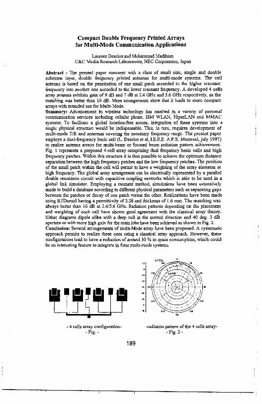
Compact Double Frequency Printed Arrays for Multi-Mode Communication Applications
Laurent Desclos and Mohammad Madihian C&C Media Research Laboratories, NEC Corporation, Japan
Abstract : The present paper concerns with a class of small size, single and double substrate layer, double frequency printed antennas for multi-mode systems. The cell antenna is based on the penetration of one small patch accorded to the higher resonant frequency into another one accorded to the lower resonant frequency. A developed 4 cells array antenna exhibits gain of 9 dB and 7 dB at 2.4 GHz and 5.6 GHz respectively, as the matching was better than 16 dB. More arrangements show that it leads to more compact arrays with intended use for Multi-Mode. Summary: Advancement in wireless technology has resulted in a variety of personal communication services including cellular phone, ISM WLAN, HiperLAN and MMAC systems. To facilitate a global location-free access, integration of these systems into a single physical structure would be indispensable. This, in turn, requires development of multi-mode T/R and antennas covering the necessary frequency range. The present paper employs a dual-frequency basic cell (L. Desclos et al, I.E.E.E. A.P.S. Montreal, july 1997) to realize antenna arrays for multi-beam or focused beam radiation pattern achievement. Fig. I represents a proposed 4-cell array comprising dual frequency basic cells and high frequency patches. Within this structure it is then possible to achieve the optimum distance separation between the high frequency patches and the low frequency patches. The position of the small patch within the cell will pennit to have a weighting of the array elements at high frequency. The global array arrangement can be electrically represented by a parallel double resonance circuit with capacitive coupling networks which is able to be used in a global link simulator. Employing a moment method, simulations have been extensively made to build a database according to different physical parameters such as separating gaps between the patches or decay of one patch versus the other. Realizations have been made using RTDuroid having a pennittivity of 3.38 and thickness of 1.6 mm. The matching was always better than 16 dB at 2.4/5.6 GHz. Radiation patterns depending on the placement and weighting of each cell have shown good agreement with the classical array theory. Either diagrams dipole alike with a deep null in the normal direction and 40 deg. 3 dB aperture or with more high gain for the main lobe have been achieved as shown in Fig. 2. Conclusion: Several arrangements of multi-Mode array have been proposed. A systematic approach pennits to realize these ones using a classical array approach. However, these configurations lead to have a reduction of around 50 % in space consumption, which could be an interesting feature to integrate in futur multi-mode systems.
- 4 cells array configuration- -radiation pattern of the 4 cells array-- Fig. - - Fig. 2 -
189

Design of an Ultra-wide Band MMW Array Fed by a Suspended Microstrip Line (SML) Network
Linping Shen, Chen Wu*, Gang-yi Deng, and John Litva*
Communication Research Laboratoiy McMaster University, Hamilton, Ontario L8S 4Kl
Email: [email protected]
*LAE Corp.,Harnilton, Canada.
Abstract
In recent years, millimeter wave(MMW) flat panel/plate antennas(FP As) have been widely used in communication systems because of their light weight, low profile, small aperture and low cost. To obtain high gain, wide bandwidth, low sidelobe and appropriate beamwidth, a kind of wideband FPA has been developed upon the previous research (C. Wu and L. Shen et al, IEEE-APS, 1998), which is fed by a low loss Suspended Microstrip Line (SML) network.
The array feed network consisting of parallel three-order power dividers, the coupling between the SML and element, and transition between waveguide and SML are analyzed by the Finite-Difference Time-Domain (FDTD) method. Good return loss and insertion loss in a wide-band 32-by-32 array antenna at the band of 17-24GHz are obtained, which are in good agreement with those from IE3D™ software of Zeland Software Inc. The feed network is an equal line length network which consists of power dividers fabricated on 0.0080" thick substrate ( e ,=3.38) with a 0.020" air gap(the array on 0.0010" substrate( e ,=4.30)). In order to obtain high gain, and to avoid the grating lobes, the array patterns in different spacings between elements are also simulated. A test fixture was fabricated to allow testing the total feed network. The measured results( amplitude and phase) agree with the simulation results. At the same time, the feed network with amplitude weighting are also simulated to obtain very low sidelobe of the array.
In order to verify the simulation results, a 32x32 array, which is fed by a suspended rnicrostrip line(SML) and actual size of the radiating aperture is about 15 .5" x 15 .5" and thickness of the array is 3 .5", is built and measured. Good antenna pattern, return loss and antenna gain (see Table) are obtained. Typical measured patterns show that the E-Plane and H-plane Cross-pol. are below 30c!B and 40c!B respectively when a single grating polarizer is added to the radome used with the array.
Table. The performance of the PFA Frequency band 18-23 GHz bands Gain (min. dBi) 34
Beamwidth ( max. 0) 2.2 X 2.2 Polarization VorH
Cross-pol. Level <-30dB SLL FCC and MPT
Front-to-back ratio >SOdB VSWR 1.5: 1
Input connector WR42 wavee:uide
190
Reactively Loaded Antenna Arrays
Andrea Borgioli*, A.S. Nagra and Robert A. York University of California,
Santa Barbara, CA 93106. [email protected]
Abstract
Underlying physical principles and significant results in reactively loaded travelling-wave antenna arrays will be presented. This study is intended to extend existing work in printed transmission line (J.R. James and P.S. Hall, Handbook of Microstrip Antennas, 1989.) to include embedded variable reactance elements in the distributed feed (A.S. Nagra and R.A. York "Distributed Analog Phase Shifter with Low Insertion Loss," IEEE Trans. Microwave Theory Tech., to be printed.) to allow for adjustment of the phase velocity in the traveling wave system, and hence control the phase distribution and beam scan direction. The reactive elements can be a simple component such as a varactor diode, or a network of MEMS capacitors. By varying the varactor bias or by tinning on and off the MEMS capacitors, we can adjust the phase velocity over a certain range determined by the tuning range of the reactive elements and by the original (intrinsic) capacitance of the line. Critical issues are beam squinting, which can be a problem for large wideband arrays, and maintaining an acceptable impedance match over the expected range of frequencies and beam patterns. In order to minimiz.e the modulation induced beam squinting two methods are provided: one involves the use of two oppositely directed arrays ("center-fed configuration"), the other consists of an array looping back on itself ("hairpin configuration"). In both cases the idea is that each half of the array is adjusted for a different effective permittivity to produce beams with opposite squint. For larger arrays, these two techniques, possible combined, find their optimal application at the sub-array level. To investigate the variation of the input impedance of the travelling-wave structure as the propagation constant is changed, results from simulations for a microstrip based array system will be presented. Since the reactances are distributed over the transmission-line, they tend to be absorbed into the characteristic impedance of the line, and an acceptable matching for a wide scan angle can be achieved. Nevertheless, if necessary, it is possible to improve the return loss by introducing a matching input section at the feed point of the array. This could also be constructed in the form of a microstrip periodically loaded with diodes or MEMS capacitors and it would be an attractive solution since the characteristic impedance of the matching section would then have the same general trends with applied bias and frequency as the radiating array itself.
In conclusion, the simplicity of the design makes reactively loaded antenna systems very attractive for a variety of applications (remote sensing, communications, radio astronomy) in which a limited scan coverage is needed
191

"Design of Linearly Polarized Parallel Plate Slot Antennas"
J.Agustin Garcia-Hidalgo1·, M. Sierra Castafier1
, M. Sierra Perez', M. Vera Isasa2
1Signal, Systems and Radiocommunications Department. Polytechnic University of Madrid. Ciudad Universitaria, 28040 Madrid. Spain
2Communications Technologies Department. University of Vigo. E.T.S.I. Telecomunicaci6n. 36200 Vigo. Spain.
The authors propose a design method for calculating the position and length of the slots in a linearly polarized parallel plate slot antenna for 12 GHz. The beam is tilted 5° in order to improve the reflection coefficient and to reduce the grating lobes level. The antenna is filled with a dielectric of low constant, to reduce the total cost of the antenna. The feeding system is a resonant slotted waveguide placed at the bottom of the parallel plate.
A broadside linerly polarized parallel plate slot antenna working at 11 GHz was proposed ([I] J.Hirokawa, M.Ando, N.Goto "Waveguide-fed parallel plate slot array antenna", IEEE Trans. Antennas Prop., vol. 40, pp. 218-223, Feb.1992). In this paper we propose a design in which a low constant dielectric fills the parallel plate waveguide and air fills the rectangular waveguide which excites the radiation slots. To minimize the reflection coefficient of the structure the beam is slightly tilted.
The slots are placed on the upper plate, designed to get uniform amplitude and the convenient phase to get the desired beam tilted. Due to the problems derived from the disposition of the radiant slots in the parallel plate waveguide, mainly a high reflection coefficient and high grating lobes, the design is not simple. Hence, we have chosen a gradient optimization method to find the locations of the slots and their lengths, but making some simplifications to reduce the number of variables involved: all slots in a column have the same length and are separated the same distance.
The design method is as follows: the elemetary radiation structure is a column of slots. The initial position and length of the slots are obtained calculating the power coupling and electric field phase change of a column of slots as functions of the slot lengths, in order to get a total power coupling, and in phase excitation. A gradient optimization method is applied. The optimization function includes the typical deviation of the amplitude on each slot and the phase with respect to the desired tilt. This computation is executed with the analysis showed in ([2] M.P.Sierra, M.Vera, A.G.Pino, M.S.Castafier, "Analysis of slot antennas on a radial transmission line", International Journal of Microwave and Millimeter-Wave Computer-Aided Engineering. vol.6, n° 2, pp.115-127, Feb. 1996). The maximum length of each slot is constraint to the resonant length. The optimization is executed in two iterative steps: first the length is optimized and second the position of the slots.
Numerical results and measurements will be showed at the conference.
192

A Ridge-Guide Travelling Wave Slot Antenna Design Methodology Using FEM and Generalized S-Parameters
*Eric W. Lucas, David Sall, and Thomas P. Fontana Northrop Grumman Corporation, Electronic Sensors and Systems Division
P.O. Box 746, Baltimore, Maryland 21203
In this presentation, a new methodology is described for the design of a class of ridge waveguide travelling-wave slotted array antennas. In this configuration, all of the array broadwall slots are located along the centerline of the waveguide. Slot coupling is achieved by an alternating ridge-trough regions within the waveguide itself. Standard method of moments slot array analysis is not fully applicable to this geometry due to its complex internal structure with alternating ridge-trough regions. We have therefore used a vector finite element model to calculate the generalized S parameters of a variety of isolated slot-step-coupling regions. The radiation environment seen by the slot is modeled with the infinite periodic cell technique in conjunction with theFloquet boundary element expansion. Here we approximate the external mutual coupling environment of the large finite array, while simultaneously maintaining computational tractability by using the vector Floquet harmonic expansion to terminate the finite element domain. Multi-mode S parameters are computed accurately by the FEM and then tabulated and curve fit using a multidimensional least square algorithm. A cascaded matrix technique was then employed to model the finite array of slots, thereby including significant internal mutual coupling, reflection and propagation effects. This technique is essentially a matrix generalization of the well-known cascaded reflection coefficient concept. Ohmic losses from finite conductivitywaveguide walls are also included in the analysis. An optimization technique was used to synthesize the coupling profile along the slotted "sticks"to achieve a prescribed aperture distribution. The array was designed entirely by computer modeling requiring no slot data' or preliminary test pieces to characterize the slots. Upon fabrication, measured results were observed which agreed well enough with the numerical predictions such that no design iteration was deemed necessary to satisfy the system requirements.
193

A computer based approach to the design of a slot array antenna
Eugen Arnold, Markus Boeck*, Gerald Grupp,Wolfgang Haselwander, Peter Ruetzel and Albert Schlaud
Daimler Chrysler Aerospace AG, V AES 1, 89077 Ulm, Germany
1 Abstract The authors developed a computer based method for the description , analysis and design of a resonant slot array antenna. This type of antennas are often used in airborne applications. 2 Model of the slot array antenna The whole antenna is divided into seperate functional blocks. All functional blocks are described using normal S Matrix. For the analysis of the antenna, the blocks are put together by matrix operation. The S Matrices of the blocks ( i.e.: the radiation slot plate or the wave guide power dividers in the feeding network ) can be calculated with different methods. The main functional blocks of the antenna are : - the radiating slot plate ( modelled as a finite array ) - the radiating and feeding waveguides ( modelled with FDTD and mode matching methods ) - the feeding network ( with wave guide power dividers , wave guide bends and other typical wave guide components . These components are modelled with FDTD and mode matching methods ) 3 Results Fig 1 shows the predicted and the measured antenna pattern of the array at a typical operating frequency
farfleld pattern
slmulaUon·51--l--+-+---1-~l---lll--+-+-..,,.asure ent ---·
·10 f--+----1--l----l--1--lll----l--l---1--+---l-___..:
·15 l--1----!--1--1--1---111----!--1---l---l---1--
·20 l--1----!--1--1--1---lll----!--l---l---l---l------
a • ~ • M O ffl ~ ~ ~ ~ W azimuth pattern [deg]
Fig 1 antenna farfield pattern at a typical frequency
194

A SIMPLE DOUBLE-SLOT RADIATOR FORE-PLANE BEAM CONTROL
Ming-Ju Tsai Wireless Research Laboratory Lucent Technologies Murray Hill, NJ 07974
Benjamin Rulf Wireless Technologies Lucent Technologies Whippany, NJ 07981
Designers of wireless communications aitennas are often faced with challenging specifications, which include control of the beamwidth in both E- and H- planes. Rectangular microstrip patch antennas are often selected as radiating elements in communications antenna arrays. In these elements the designer has some control over the beamwidth in the H-plane by varying the width of the patch size. In the E-plane, however, the patch!; dimension is determined by the frequency, making beamwidth control much more difficult.
We have developed an antennaelement consisting of two parallel slots on a ground plane, shown in the figure below. By adjusting the distance (d) between the slots (which form a 2-element array), we can control the E-plane beamwidth, since each slot has a pretty wide beam in the E-plane. The ground plane is the x-y plane, and the antenna radiates into the z>O half-space. Two non-resonant cavities in the back of the slots reduce the undesired radiation into the z<O half space. They increase the antenna!; efficiency and affect the antennas frequency response but they do not have a significant effect on the radiation pattern.
The double-slot antennas simplicity, low cost, and very low profile make it a good candidate for use in situations where the E-plane beamwidth is an important system parameter. The preliminary design was simulated with the commercial tool IE3D (from Zeland Software Inc.), which is a full-wave 3D electromagnetic solver for planar structures using the method of moments. Both simulated and measured results will be presented in the conference.
Top View
Y (E-Pbne)
t CavityWall
Scale tz
A Cavity,all ~ Reflecta
(b) ~-----------~~ X(H-Plane)
(a)
Figure: (a) Top view of double-slot antenna element, (b) Side view, cut A-A.
195

Low-Cost Semi-Cylindrical Airborne Phased Array for Radar Applications using Circular-Polarization for Rain-Clutter Suppression
G. T. Thompson, J. K. Tillery*, and J. J. H. Wang Wang Electro-Opto Corporation Marietta, Georgia, USA 30067
http://www.weo.com
There is a need for low-cost phased arrays for all-weather radar applications in which precipitation clutter must be suppressed. It is well-known that for radars circular polarization (CP) has a 15-20 dB advantage in signal-toclutter ratio than linear polarization. It is also well-known that a CP radar signal is more effective in detecting real complex targets than linear polarization, and has a virtually guaranteed echo since certain targets such as a thin horizontal structure can be invisible to a vertically polarized radar signal.
A low-cost high-performance integrated antenna/phase-shifter array module has recently been developed (Wang et al, 1996 IEEE Phased Array Symp. Dig.; pp. 15-18, Boston, Oct 1996). This phased array module employs the circularly-polarized SMM antenna and its inherent phase pattern that can be efficiently controlled at low cost since phase shifting mechanisms account for the largest part of the high cost of phased arrays. This array module is being employed in a phased array design for an all-weather airborne radar with ultrawide azimuth scan achieved by using a semi-cylindrical array architecture. The semi-cylindrical array allows a simple, curved tile construction amenable to lowcost production.
This array is capable of wide bandwidth, and its semi-cylindrical configuration virtually eliminates the beam squint problem suffered by planar arrays in wideband scanning operations. Other merits of the integrated antenna/phase-shifter include low driving power and low insertion loss. The array module design can be readily modified for ultra-low noise and ultra-low driving power by replacing the PIN diodes in the feed region of the spiral antenna with MEMS (Micro-Electromechanical Systems) switches because of their compatibility in physical structure, fabrication process, and driving/control network. Further performance enhancement can be achieved by employing the ultra-wideband and potential polarization diversity features of the integrated antenna/phase-shifter module.
Small array experimentation and system simulation have been carried out to demonstrate the feasibility and merits of this new design approach.
196

PHASED ARRAYS FOR GROUND BASED SATELLITE PAYLOAD AND CONTROL APPLICATIONS
Boris Tomasic* Air Force Research Laboratory
31 Grenier Street Hanscom AFB, MA 01731
Shiang Liu The Aerospace Corporation
P.O. Box 92957 Los Angeles, CA 90009-2957
Within the next decade, there will be a dramatic increase in the number of commercial and military satellite constellations providing world wide telecommunication, environmental, navigation and surveillance services (B. Miller, IEEE Spectrum, March 1998). The satellites, at LEO, MEO and GEO orbits, will need a number of ground based stations to serve as the gateway for payload message/data routing and/or as the control center for satellite tracking, telemetry and command (TT &C) operations. A typical ground station will require one or more high performance, large antennas with hemispherical coverage for communicating with LEO and MEO satellites during the brief interval from their rise above the horizon until they drop out of sight.
Three main types of antennas can be used for satellite ground stations: mechanically steerable reflector antennas, electronically steerable arrays (ESA) and microwave lens antennas. Although mechanical reflectors are most widely used for satellite communications, ESA are the optimum choice for this application because they can provide multi-function, multiple simultaneous beams, have high reliability, graceful degradation, require low maintenance, and have low life cycle cost. With rapidly emerging MMIC, multilayer beamforming and beam steering technologies, large ESA are viable candidates for ground based station antennas, and by using commercial off-the-shelf components, they could be also affordable.
Because hemispherical coverage is reqiured for ground station antennas, there are only a few potential array architectures that meet this requirement. They can be classified in three major groups: (1) multi-face planar arrays, (2) curved surface or conformal arrays, and (3) lens arrays/antennas. In this paper we present design trade-offs of these array architectures. We show that spherical array is the optimal choice for ground based satellite control antennas in terms of performance and cost (H.E. Schrank, Phased Array Antennas, Artech House, Inc., 1972). It is a natural array geometry that provides hemispherical coverage with uniform gain pattern. We show that the spherical array requires about 30 % fewer elements than the multi-planar phased array (G.H. Knittel, IEEE Trans. on Ant. And Prop., Vol AP-13, Nov. 1965). It is also shown that spherical arrays exhibit significantly larger instantaneous bandwidth and have lower polarization and mismatch losses than other types of array architectures. In addition, we will discuss the optimum excitation for a spherical array which maximizes the gain and significantly reduces the required input power. However, the implementation of multi-beamforming network, fabrication, and assembly of spherical arrays are much more difficult than for the planar arrays. An architecture design that preserves all the advantages of spherical phased arrays for hemispherical coverage while the fabrication is based on well developed, easy manufacturable planar array technology will also be proposed.
197

THIS PAGE INTENTIONALLY LEFT BLANK
198

\Vednesday i\1orning JOINT AP/URSI A Session 65 Convention Center Ballroom III
WIDE BANDWIDTH ANTENNAS Session Chairs: W. Wiesbeck and J. Tillery
8:05 Opening Remarks
8: 10 Low-power low-profile multifunction helmet-mounted smart array antenna, J. Tillery*, G. Thompson, J. Wang, Wang Electro-Opto Corporation, USA
8:30 Planar trapezoidal and pentagonal monopoles with impedance bandwidths in excess of 10:1, J. Evans*, M. Ammann, Dublin Institute of Technology, Ireland
8:50 Broadband robust, low-profile monopole incorporating top loading, dielectric loading, and a distributed capacitive feed mechanism, J. McLean*, H. Foltz, G. Crook, University of Texas, USA
9: 10 Self-similar surface current distribution on fractal Sierpinski antenna verified with infra-red thermograms, M. Navarro, J. Gonzalez, C. Puente, Universitat Politecnica de Catalunya, Spain, J. Romeu, Universidad de Zaragoza, Spain, A. Aguasca, Universitat Politecnica de Catalunya, Spain
9:30 Characteristics of digital terrestrial broadcasting antennas, Y. Ojiro*, Y. Iitsuka, S. Kogiso, H. Kawakami, G. Sato, Antenna Giken Co., Ltd., Japan, S. Sumihiro, Shibaura Institute of Technology, Japan
9:50 Break
10: 10 Design of a TEM waveguide for ultra-wideband applications, H. Pao, A. Poggio, Lawrence Livermore National Laboratory, USA
10:30 A multi-branch monopole antenna for dual band cellular applications, D. Liu, IBM, USA
Page
10:50 A compact, ultra-wide-band antenna for ground penetrating radar, D. Evans, S. 200 Claude, Applied Electromagnetics, UK, G. Gooding-Williams, G. Crisp, DERA Malvern, UK
11; 10 Integrated dipole antennas on silicon substrates for intra-chip communication, K. Kim, Kenneth Ko, University of Florida, USA
199

A Compact, Ultra-Wide-Band Antenna for Ground Penetrating Radar
David J. Evans & Shane Cloude Applied Electromagnetics, I I Bell Street, St Andrews, Fife, KYI 6 9UR, Scotland, U.K.
Gerard Gooding-Williams & Graeme Crisp DERA Malvern, St Andrews Road, Malvern, Worcs., WRl4 3PS, England, U.K.
Hand-held Growtd Penetrating Radar (GPR) equipment using Ultra-Wide-Band (UWB) radiation requires broad band antennas that are compact and light weight. An existing design (E. A. Theodorou et al., Proc.IEE Pt. H, 128, 124-130, 1981), a resistively loaded 'kipper" horn shaped in an attempt to provide a smooth impedance transition from the feed to free space, gives acceptable performance but is too large for the application at 50cm in length. An antenna of similar performance was required that will fit in a cube with side approximately 30cm. The design of this antenna was facilitated by the use of the FDTD Maxwell Solver, INGRID.
The existing 'kipper" horn design was modelled using INGRID to measure its performance. This gives a reasonable amplitude transmission across the frequency range of use, 200MHz to 800MHz, and is similar to an ideal aperture antenna over this range. The feed point impedance is reasonably flat at arowtd 50Q, the source impedance. It was fowtd that the shaped horn alone is not very effective and it is only with the addition of resistive terminations at the aperture that the performance becomes acceptable. The optimal shaping depends on the frequency so it is difficult to achieve a wide band antenna with minimal reflection from the aperture.
Since the most effective part of the existing design is the terminating resistances and because efficiency is not deemed to be a high priority for this application, it was decided to investigate the use of terminated TEM horns. A basic TEM horn with impedance of 50 Q, and restricted to fit the 30cm size, was modelled as a starting point. With terminating resistances this performs reasonably well. However there are strong rear lobes evident in the radiation pattern, as there are for the 'kipper"horn, which would cause problems with the GPR equipment. Using an idea first put forward by Carl Baum (Phillips Lab. Sensor and Simulation Notes, 377, 1995, terminating resistances were placed at the rear as well as the aperture. Connections to these were made via plates similar to those used for the antenna itself. The was fowtd to reduce the rear lobes and improve the directionality, whilst not diminishing the quality of the impedance and transmission. The forward transfer function for the 'kipper" horn, the new design, a COmpact Directive Antenna (CODA), and its realisation in experiment is shown in Figure I below.
Comparison of U'.'V8 Antenna i=orward Transfer Funcuons
200

Wednesday Morning URSI F Session 67 Japanero
PROPAGATION IN URBAN SCENARIOS Session Chairs: W. Vogel and A. Moustakas
8:05 Opening Remarks
Page
8:10 Prediction of propagation characteristics in urban environments with various 202 distributions of building rows, N. Blaunstein, Ben-Gurion University of the Negev, Israel
8:30 A recursive beam-splitting algorithm for forward ray tracing, M. Sabbadini, Esa Estee, 203 Toe Netherlands, E. Di Giampaolo, F. Bardati, DISP, University of Roma ''Tor Vergata", Italy
8:50 A combined path loss model for small cell propagation prediction in cities, S. 204 Naruniranat, Y. Huang, D. Parsons, University of Liverpool, UK
9:10 Measurements on waves penetrating through trees, H. Li, Y. Lin, H. Lin, T. Liu, 205 National Taiwan University, Taiwan
9:30 Radio wave propagation at 10 GHz in tunnels, M. Lienard, S. Betrencoun, P. 206 Degauque, University of Lille, France
9:50 Break
10: 10 Interference effects on capacity of wireless propagation in a multipath environment, 207 A. Moustakas*, H. Baranger, L. Balents, S. Simon, Lucent Technologies, USA
10:30 Envelope correlation, power imbalance, and diversity gain of spatial, polarization, and 208 pattern diversity for hand-held radios in multipath channels, C. Dietrich*, K. Dietze, K. Takamizawa, W. Stutzman, Virginia Polytechnic Institute and State University, USA
10:50 Azimuth and elevation power angular profile computed from satellite mobile 209 measurements, L. de Haro, S.S.R., Spain, L. Braten, Telenor R&D, Norway, M. Sanchez, Universidade de Vigo, Spain
11:10 Joint spatial and temporal characteristics of the indoor wireless channel at 2.4 GHz, B. 210 Hunter, J. Wallace*, M. Jensen, Brigham Young University, USA
11 :30 Level-crossing rate and average duration of fades in Nakagami-Hoyt fading channel, 211 N. Youssef, Ecole Sup. des Communications de Tunis, Tunisia
201

Prediction of Propagation Characteristics in Urban Environments with Various Distributions of Building Rows
N. Blaunstein Department of Electrical and Computer Engineering, Ben-Gurion University of the Negev, P.O. Box 653, Beer Sheva 84105, Israel
Tel: 972 7 6461 589, Fax: 972 7 6472 949, e-mail: [email protected]
Abstract From the viewpoint of radio wave propagation modem cities are complicated
areas and the analytical description of propagation phenomena cannot be presented without certain simplifications.
In the UHF/L-frequency band large buildings are practically non-transparent for radio waves and their sizes are substantially larger than the wavelength value, 1.. . Moreover, all the specific properties of the city topography form unique conditions for wave propagation inside the street level.
In such a situation the use of accurate deterministic models is very time-consuming even if it is, in principle, a possible procedure. On the contrary, a relatively simple statistical model could provide a sufficiently accurate description of the average field parameters in the building layer. To obtain a statistical description of the urban terrain, we need detailed information about the spatial distribution of buildings and natural obstructions surrounding the receiving and transmitting antennae.
The method described in this work is based on the statistical approach and requires only statistical parameters of the terrain and environment, as well as the locations of both terminals, transmitter and receiver, to obtain loss characteristics in various situations in the urban scene. In addition to that this method provides an estimate of cell radius, which is the average distance of line-of-sight (LOS) between terminals in an area investigated. This parameter is very important for determining the number and location of base stations in a cellular wireless system. An array of randomly distributed non-transparent screens placed on the rough ground surface has been considered in [l, 2]. Following the approaches presented in [1-4], we introduce the mu/tis/it waveguide model [1-3} and the parametric model [4] to evaluate the average intensity of the total field in built-up areas with regularly distributed rows of buildings and with randomly distributed buildings, respectively, taking into account multi-reflection and multiscattering phenomena, and the diflraction from the buildings' comers.
We present the results of experiments carried out by the communication group of TADIRAN Telecommunications Ltd. in various urban areas with regularly and irregularly distributed buildings. This result is compared with the theoretical prediction based on both the waveguide and parametric models.
References [1] N. Blaunstein and M. Levin, Radio Sci., vol. 31, pp. 313-323, 1996. [2] N. Blaunstein and M. Levin, Radio Sci., vol. 32, pp. 453-467, 1997. [3] N. Blaunstein, R. Giladi, and M Levin, IEEE Trans. Vehic. Tech., vol. 47, No. 1, pp. 11-21, 1997. [4] N. Blaunstein and M. Levin, Proc. of IEEE Antennas and Propagation Society Int. Symp. 1998, Atlanta, Georgia, June 21-26, 1998, vol. 3, pp. 1684-1687.
202

A Recursive Beam-Splitting Algorithm for Forward Ray Tracing
Marco Sabbadini1, Emidio Di Giampaolo' and Fernando Bardati2
1Esa Estee, Noordwijk, Netherlands 2DISP Universita'di Roma Tor Vergata, Roma, Italy
In the scattering analysis of electrically large and complex structures, the scattered field is detennined by means of GTD (Geometrical Theory of Diffraction) or other high-frequency approximations. A ray tracing identifies the paths along which energy propagates from the source to the observation region. The complete scene is scanned to determine which portions are illuminated by the incident field and give rise to waves toward other objects or the observation region. The scattered field will give rise to new, second level, scattered fields and so on. Increasing the complexity of the scene results in an exponential increase of the complexity of ray tracing process.
Two different approaches can be adopted to determine the ray paths, backward ray tracing and forward ray tracing. In backward ray tracing the source point and the field point are specified and the (generalised) Fermat!; principle is applied to determine the ray path between them. For multiple interactions this leads to the solution of non-linear systems of equations and to the difficulty of an exaustive search to find all (significant) interactions. Forward ray tracing potentially avoids these problems using rays cast in all directions. Its main drawbacks are the very large number of rays required to properly cover the scene and some difficulties in handling multiple diffraction. The object of this paper is a forward raytracing algorithm that overcomes the limitations of existing ones.
The basic numerical problem in ray tracing is to identify the scattering surface hit by a 'propagating"ray. In computer graphics a technique known as recursive binary subdivision is often used to reduce the time required to identify the impact of optical rays on objects within the scene. The first novelty of the present algorithm is the use this technique in combination with a similar scheme for the rays themselves to minimise their number. A few rays are uniformly cast from the source and the information gathered tracing them is used to increase the ray density where necessary.
In forward ray tracing, higher-order interactions can be modelled by secondary sources radiating in a specified angular region. It is then very important that the description of the scene used be independent from the source position. Higher-order ''sources" are also constrained by the geometric features of scatterers by the associated scattering mechanism. To honor these constraints the new algorithm resorts to the beam tracing concept developed in computer graphics, that removes the need of ray path corrections. This also reduces the final detennination of the total electromagnetic field in the observation region to a simple interpolation over an irregular triangular mesh, for which very fast algorithms are available.
The introduction of recursive subdivision and beams in a forward ray-tracing scheme overcomes the typical problems of ray tracing and leads to a very efficient scheme for the evaluation of electromagnetic scattering in complex environments.
203

A Combined Path Loss Model for Small Cell Propagation Prediction in Cities
Sakda Naruniranat, Yi Huang, and David Parsons Department of Electrical Engineering and Electronics
University of Liverpool, L69 3GJ, UK
A considerable effort has been devoted to the radio propagation modelling in an urban environment for the past ten years since the communication traffic has increased dramatically and the cell size has become much smaller than that of conventional cells. Meanwhile more radio based systems and services are forecast. It is apparent that the interest in small cell radio communication system will be maintained in the foreseeable future.
Traditionally, empirical or statistic radio path models have been successfully applied to large cells in both rural and urban environments. These models are relatively simple mathematically and easy to implement. However, for small cells, these models are no longer valid since the radio path loss varies significantly from one site to another. The reflection and transmission are functions of many parameters, such as frequency, polarisation, incident angles, dielectric constant and thickness of walls. It becomes apparent that site-specific techniques must be used to predict the propagation in such small cells (M. C. Lawton and J.P. McGreehan/EEE Trans. on Veh Technol. 1994, 43, pp. 955-968, W. K. Tam and V. N. Tran, Electronics and Communication Eng Journal, 1995, 7, pp. 221-228, G. Liang and H.L. Bertoni, IEEE Trans on Ant and Prop, 1998, 46, pp. 853-863). The major advantage of using site-specific modelling techniques is that all wave reflection, transmission and diffraction can be taken into account thus accurate prediction may be obtained. Ray-tracing algorithms and finite-difference time-domain (FDTD) methods have been identified as the most promising approaches to be employed for the system planning tools. However, all site-specific techniques are limited by computation resources and only suitable for small picocells.
A novel path loss model, which is a combination of empirical and site-specific models, is proposed in this paper. This method offers reasonable accuracy but without suffering from computational difficulties for small cells. Basically, the total path loss in a cell takes the following form
L (dB) = ao + a1 log (j) + a, log (d) +a3 (m) + a4 (n)
where f is the frequency; d the separation between the Tx and the Rx; m and n are the numbers of walls and floors between the Tx and Rx respectively;a; (i = 0, I, ... , 4) are constants to be determined by ray-tracing techniques for a small area within the cell. A vector 3-D ray-tracing code, which takes all reflected, transmitted and diffracted rays into account, is first applied to a typical area in the cell so as to determine the constantsa,, which are mainly functions of the building materials and structures. Having obtained the parameters, the combined model can then be implemented to the entire cell. In addition to the operational frequency, polarisation and separation between the Tx and Rx, some site information, such as the number of walls and floors, are required for this model. Detailed site information on the building materials dielectric properties and thickness of walls/floors are also required for a small area. Computation at 900 MHz and 1800 MHz have demonstrated that this method is relative efficient and satisfactory results are obtained.
204
Measurements on Waves Penetrating Through Trees
Hsueh-Jyh Li, Yu-Tse Lin, Han-Chiang Lin, Ta-Yung Liu Institute of Communication Engineering
National Taiwan University Taipei, Taiwan
R.O.C.
An ordinary way to measure the attenuation constant of wave penetrating through tree is to measure the amount of attenuation at a single frequency for different penetration depths. This method may work well if there is no other significant reflections or scattering from other objects. In the presence of multipaths, the field measured is the superposition of all path components. When the magnitude of the wave directly penetrating through trees is comparable to or smaller than those of other path components, the results obtained will be incorrect.
The electrical length of the wave penetrating through trees will be different from the real penetrating length by a factor of the effective dielectric constant Elerr of trees. One may think that leaves and branches contain ingredient of water. Therefore, the effective dielectric constant of trees will be much different from that of air. However, the whole volume of trees contains branches, leaves and air. The effective dielectric constant of the whole trees needs be determined by measurements
It is known that wideband measurements can separate multipaths. Therefore the attenuation properties of the direct penetrating wave can be obtained by isolating the desired path from others even in an environment with multipaths.
In this paper we propose measurement methods for waves penetrating through trees in environments of multipaths. With wideband measurements, the direct penetrating wave can be singled out. To determine the attenuation constant and the effective dielectric constant, we choose environments with uniform tree clusters and employ wideband measurement method to derive the desired parameters. We measure the penetration loss and the electrical length of the direct penetrating path at different penetration lengths, and then derive the attenuation constant and the effective dielectric constant from the slope of the regression lines. In our measurements, the attenuation constants range from I dB/m to 2dB/m. we have found that the effective dielectric constant is very close to I no matter how dense the leaves are. This can be explained by the fact that leaves or branches only occupy a small portion of the tree volume and most volume is occupied by air.
205

Radio Wave Propagation at 10 GHz in Tunnels
M. LIENARD, S. BETRENCOURT and P. DEGAUQUE University of Lille, Electronics Dept, Bldg P3, 59655 Villeneuve d'Ascq Cedex, France
Tel : +(33) 3 20 33 71 34; Fax:+ (33) 3 20 33 72 07 email: [email protected]
The characterization of the propagation of high frequency electromagnetic waves in tunnels has already been widely studied (S.H. Chen and S.K. Jeng/EEE Trans. V.T, 45, 570-578, 1996), the frequency range of interest extending usually from 450 MHz up to about 2 GHz for UMTS applications (M. Lienard and P. Degauque, IEEE Trans V.T, 47, 1322-1328, 1998). However, it can be also important to ensure a specific train to track video or data communication and, in this case, the frequency band must be choosen in available bands for this kind of services but not necessary below or on the order of 2 GHz. It is the reason why extensive measurements have been carried out in various types of subway tunnels in order to optimize the frequency to get a range on the order of 2 km. In a straight tunnel, the attenuation per unit length is a decreasing function of frequency, at least if the roughness of the tunnel walls remains much smaller than the wavelength. For curved tunnels, any improvement has been shown for frequencies above few GHz. In order to get a good compromise between the attenuation, the transmitted power, the antenna size and the noise level, a carrier frequency of 10 GHz has been considered for this application.
The narrow band analysis has been first performed in a straight tunnel having approximately a circular shape of20n:r. The theoretical simulation is based on the usual ray theory, assuming a rectangular shape for the tunnel in order to easily determine the various images of the transmitting antenna. By plotting the variation of the field amplitude versus the distance between the transmitter and the receiver it clearly appears that the total distance can be divided into two zones. In each of them, one can define a regression line, corresponding to an attenuation expressed in dB/m, fluctuations being distributed around it. Since the tunnel geometry exhibits a translation symmetry, these fluctuations are deterministic. However if the amplitude distribution is calculated around the regression line in each zone and not around a running mean, it appears both theoretically and experimentally, that the cumulative function still follows a Rayleigh distribution. The distribution of the fading width and of the distance between fadings has also been determined.
The impulse response of the channel is deduced from the theoretical results through a Fourier transform of the transfer function. In this case isotropic transmitting and receiving antennas have been assumed in order to characterize the channel itself and a bandwidth of 150 MHz was simulated. The delay spread depends on the distance transmitter-receiver since, at short distance, multiple reflected rays are not too much attenuated while, far from the transmitter, rays reflected on the walls with a grazing angle of incidence are dominant and, consequently, the delay spread decreases. This clearly appears from the representation: delay - angle of arrival - amplitude which has
206

Abstract Submission for the 1999 IEEE AP-S International Symposium and USNC/URSI National Radio Science Meeting
Title: Interference Effects on Capacity of Wireless Propagation in a Multipath Environment
Authors: Aris L. Moustakas*, Harold U. Baranger, Leon Balents and Steven S. Simon
Address: Bell Laboratories, Lucent Technologies, 600 Mountain Avenue, Murray Hill, NJ 07974
Abstract:
We show that the amount of information that can be transmitted by electromagnetic propagation in coherent diffusive media can be larger than that for free space. In the presence of scattering there are a large number of statistically independent paths, which interfere at both the transmitter and receiver. By introducing a cluster of antennas on both ends properly placed at distances of the order of the wavelength from each other, the interference can be made to be destructive. As a result, the number of channels carrying independent information increases roughly linearly with the number of antennas on each side ~- J F oschini and M. J. Gans, Wireless Personal Communications 6: 311-335, 1998). In contrast, multiple antennas spaced similarly in free space do not increase the capacity over a single transmitter and receiver. We analyze this interference in the context of wireless communications using diffusive models and different geometries and obtain quantitative predictions for the capacity limits in various simple geometries. In particular, we calculate the capacity in the case of isotropic diffusion. Furthermore, we analyze the correlations in a half-infinite diffusive space, modeling approximately the existence of open space over buildings. We show that close to the surface dividing the two regions, the orientation of the antenna array significantly affects the capacity. Finally, we find the correlations for anisotropic scattering and specifically for the situation where the scattering is angle dependent, such as scattering from walls, buildings etc (D. Ullmo and H. U. Baranger, IEEE Trans. Veh. Technol., in press).
207

Envelope Correlation, Power Imbalance, and Diversity Gain of Spatial, Polarization, and Pattern Diversity for Hand-Held Radios
in Multipath Channels
Carl Dietrich*, Kai Dietze, Koichiro Takamizawa, and Warren Stutzman
Bradley Department of Electrical and Computer Engineering Virginia Polytechnic Institute and State University
Blacksburg, VA 24061-0111 Phone: (540) 231-6834 Fax: (540) 231-3355
www.ee.vt.edu/antenna
Antenna diversity systems for base station applications have been thoroughly investigated. These systems typically employ spatial diversity with antenna spacings on the order of ten wavelengths. Hand-held radios tend to operate in environments with multipath components having a larger angular spread. Under these conditions decorrelated branches for diversity combining can be obtained with smaller antenna spacings, particularly at high frequencies. Polarization and pattern diversity can also be exploited. For small antenna spacings mutual coupling can decorrelate what would otherwise be similar antenna patterns. This was shown to result in branch cross-correlations below the theoretical value based on omnidirectional antenna patterns (R. G. Vaughan and N. L. Scott, Radio Sci., 6, 1259-66, 1993).
This paper examines the fundamental mechanisms that affect diversity performance, spatial separation, polarization, and pattern, and the interplay between these mechanisms, by varying each parameter independently to the extent possible. Better understanding of these mechanisms can lead to better diversity system designs, within the constraints of packaging.
This paper presents measurements of pattern correlations for hand-held diversity antennas, and subsequent measurements in line-of-sight, urban, and indoor multipath channels using spatial, polarization, and pattern diversity. Diversity gains as well as envelope correlations, and power imbalances are calculated from the measurements. Differing antenna polarizations or pattern distortion due to mutual coupling result in power imbalance between branches. Diversity gainfor a given cross-correlation decreases as the power imbalance increases. The use of diversity gain is essential to enablea direct comparison of the actual performance that can be achieved with each configuration. Envelope and pattern correlations are also compared. Recommendations for practical diversity antenna implementations are made based on the results.
208

Azimuth and Elevation Power Angular Profile Computed from Satellite Mobile Measurements
Leandro de Haro1, Lars Bniten2 & Manuel Garcia Sanchez'
1S.S.R., ETSIT, UPM, E-28040 Madrid Spain. Ph.: +34 91 5495700, Fax: +34 91 5432002 2Te!enorR& D. N-2007 Kjeller. Norway, Ph.: +47 6384715, Fax: +47 63 819810 3T.d.C, Universidade de Vigo, Spain, Ph.: +34 986 812195, Fax: +34 986 812116
Land mobile satellite systems are scheduled to provide personal and data communications in several different environments within a few years. To a large extent, the propagation channel features detennine the system design. An important parameter which should be used in system planning and smart antenna design is the power angular profile (p(a,~))
representing the power arriving with azimuth angle a and elevation ~, both relative to the visibility angle toward the satellite. Some authors, (e.g. Lee, W. C. Y. , "Finding the Approximate Angular Probability Density Function of Wave Arrival by Using a Directional Antenna", IEEE Trans. on AP, vol. AP-21, May, 1973), demonstrate that neglecting these direction dependent parameters would yield errors when characterising radio channels that include directional receiver antennas, while practical measurement of p(o:,~) can be difficult.
In this paper the power angular function is derived by means of a statistical processing of propagation measurements conducted by INMARSAT in the UK at 13° and 29° elevation angles using three different geoestationary satellites (lnmarsat-2 AOR-E, MARECS B2 and lnmarsat-2 AOR-W) seen from London at 29,3°, 29,4° and 13° respectively. Simultaneous recordings were made at L-band using both directive (9, 11 dBi) and omni-directional antennas (2 dBi). Those recordings contain the received carriers down-converted to baseband, antenna pointing direction, car heading and speed. The measurement took place in four test routes in the suburbs of London (highway -lightly wooded, heavily wooded road, suburban route and urban area) representing propagation conditions from line-of-sight to shadowing or blocking. Experimental set-up and route description can be found in (L.E. Braten et al., "Modelling of land mobile satellite channeles based on measurements at 13° and 29° elevation angle", Proceedings of the International Conference of Antennas and Propagation conf, Edinborough, 1997).
The power angular function, p(a,~), is derived under the hypothesis that the function is separable in the azimuth and elevation variables, p(aJ) = p.(a)p,(~). The calculations of
Pa( o:) considering a very narrow elevation beam will be done in terms of the Scattering function S(v). Following the procedure proposed in (W.C. Jakes. "Microwave Mobile Communications". IEEE Press, 1994.) the scattering function of a receiving antenna with known directional pattern would permit finding p.(o:) (for the same antenna polarisation) if the receiving antenna radiation pattern is symmetric around o:= 0°:
p.(a)=-1
-S(v)vm~l-( v )' (l) 2-G(a) Vm
Different models for the function pp(~) (Aulin' s, Parson's, etc) will be tested to obtain power elevation function performance. Integrating S(v~dvl = p.(o:)p,(~)G.(o:)G,(~)dn
along a line of a constant azimuth <Xo, gives a relation of pp(~) in function ofp.(o:), so that values for some parameters of pp(~) may be obtained.
In the presentation results for the power angular profile for the measured environments will be presented. The effect of error in the vehicle speed as well as the ones produced by the satellite orbit inclination will be taken into account.
209
Joint Spatial and Temporal Characteristics of the Indoor Wireless Channel at 2.4 GHz
Brandon R. Hunter, Jon Wallace*, and Michael A. Jensen Department of Electrical and Computer Engineering
Brigham Young University Provo, UT 84602
In recent years, we have witnessed an explosion in the wireless communications arena. Given the resulting infrastructure and technology development, it is evident that wideband digital communications for the indoor environment are becoming increasingly practical. However, one of the factors which has slowed the deployment of such systems is the propagation environment which leads to multipath signals with significant temporal and angular spreading. The intersymbol interference (ISi) resulting from this multipath propagation can place severe restrictions on the achievable system data rate. One potential method for reducing ISi and increasing the data rate is the use of "smart" antennas capable of adapting the antenna response. However, evaluation of the performance of different antenna configurations and the driving algorithms requires a detailed understanding of the multipath temporal and spatial characteristics.
This paper summarizes results from a measurement and modeling campaign aimed at furthering our understanding of the indoor multipath environment at 2.4 GHz. The measurements are performed using a custom data acquisition system which exploits directional antennas and a broad-band transmitter/receiver pair to probe the temporal and spatial signal characteristics. The raw data is processed using the CLEAN algorithm to produce the arrival time and angle for each individual multipath component. Temporal and spatial resolutions of up to 2 ns and roughly 3' are achieved using this approach. Measurements are taken in a variety of indoor environments in order to provide insight into the effects of building construction on the multipath response. The measured results are used to develop a simple statistical model for use in simulating the performance of different smart antenna configurations. This model is based upon the findings that the multipath components generally arrive in two to five groups or "clusters" in space and time, with several individual arrivals appearing within each cluster.
The presentation will focus on the data acquisition system, including its underlying architecture, design and fabrication, and deployment. Propagation data collected in several different indoor environments will be summarized, and key features of the multipath joint spatial and temporal characteristics will be highlighted. The presentation will provide a detailed discussion of the model developed from the observed multipath responses as well as examples of how to use the model in assessing the performance of different antenna configurations.
210

Level-crossing rate and average duration of fades in N akagami-Hoyt fading channel
Neji YOUSSEF
Ecole Sup. des Communications de Tunis, 2083Ariana, Tunisia. Fax: +216 1 856 829, e-mail: [email protected]
I. Introduction In radio transmission, the received signal amplitude is usually characterized by
rapid fading as a result of multipath propagation. Knowledge of statistics of fades and interfades are usually of great importance for the design of errors correction modules and system performances evaluation. In this work, we consider the channel the amplitude fluctuation of which is described by the Nakagami-Hoyt distribution. We derive, for this model, expressions for the fading rate as well as for the average time duration of fades and interfades.
2. Nakagami-Hoyt fading channel The probability density function of the process R(1) under study is given by:
R R 2 1 I R2
I I p(R) = ~ exp(- - (-+-))I (-c- --)) , where bx and b are the variances
bb 4bb 0 4bb Y Xy X y y X
of two low-pass Gaussian processes x(r) and y(r), respectively, and / is the zero-order 0
modified Bessel function of the first kind.
3. Fade and interfade statistics The fading rate related to the process R(t) can be obtained from the well known
expression given by, N = I R0
p(R, R0
)dR0
• The quantity N, for a crossing level R0
is found
tobe:
N
R fs R 2 2n ------ R 2
---'0"---exp(-__Q_P) I b +(b -b )co.2eexp(-__Q_(P -/J )co.29))d9, (21'// 2 b b 28 X O y X y 28 y X
X y
,2 -2- 1/2 wherepx=x (<l,Py=y' (r)andB=(b///yl .
The average duration of fades is derived from the following
R 1/2 0
R i (b b ) /exp(-r(b +b )I (r(b -b )dr . J0
o p(R)dR . x Y O x y o x y expression, r = N to be. t =
f f N
In a similar manner, we obtain the average duration of interfades, •,
R
I- (b b / 12 fexp(-r(b + b ))/ (r(b -b ))dr
XY O X y O X y tn = ------"-----------
N All the above results can be shown to include the case of the Rayleigh fading channel.
211

THIS PAGE INIENTIONALLY LEFf BLANK
212

Wednesday Morning URSI B Session 68 Convention Center Ballroom XII
EFFICIENT METHODS FOR MATRIX GENERATION OR SOLUTION Session Chairs: F. Canning and V. Cable
8:05 Opening Remarks
Page
8: 10 The CG-NUFFT method for inhomogeneous media, X Xu•, Q. Liu, New Mexico 214 State University, USA
8:30 The nonuniform fast Hankel iransform and its applications for integral equations, Q. 215 Liu, Z. Zhang•, New Mexico State University, USA
8:50 The projection iterative method (PIM) solution to MOM equations with matrices 216 sparsified by a novel method, Q. Ye*, L. Shafai, University of Manitoba, Canada
9: 10 Comparison of iterative solutions of impedance matrices generated by discrete 217 wavelet tranSformations, R. Miller*, R. Nevels, Texas A&M University, USA
9 :30 An in-depth look at fast multipole with & without Galerltln, V. Cable, Lockheed 218 Martin Skunk Works, USA
9:50 Break
10:10 Fast multipole modeling of wideband scattering from large trihedral fiducial targets 219 situated above a lossy half space, N. Geng, Universitaet Karlsruhe, Germany, A. Sullivan, L. Carin, Duke University, USA
10:30 Rapid full-wave simulation of electromagnetic systems using model order reduction 220 and unstructured finite differences, L. Zhao*, ANSYS Inc., USA, A. Cangellaris, University of Illinois at Urbana-Champaign, USA
10:50 Basis-pursuits matrix compression for moment method scattering analyses, A. Barnes, 221 L. Carin, Duke University, USA
11: 10 A combined everything integral equation, F. Canning, Rockwell Corporation, USA 222
11 :30 An efficient BiCG multiple right hand sides algorithm for IE based electr0magnetic 223 analysis, B. Shanker*, F. Ng, E. Michielssen, J. Song, W. Chew, University of Illinois at Urbana-Champaign, USA
11 :50 A forward-backward iterative physical optics algorithm for cavity scattering problems, 224 R. Bwkholder, Ohio State University, USA
213

THE CG-NUFFT METHOD FOR INHOMOGENEOUS MEDIA
XUEMIN Xu* AND QING Huo LIU
KLIPSCH SCHOOL OF ELECTRICAL AND COMPUTER ENGINEERING NEW MEXICO STATE UNIVERSITY
LAS CRUCES, NM 88003
Electromagnetic wave propagation and scattering problems can be formulated as integral equations. The conventional method of moment (MOM) has been extensively utilized to solve these integral equations. However, it is well known that MOM inefficient for largescale problems, as its memory and CPU requirements arc O(N2) and O(N3 ) respectively, where N is the total number of unknowns. To overcome this limitation, the conjugategradient fast Fourier transform (CG-FFT) method has been proposed which combines the conjugate-gradient method and the fast Fourier transform in an iterative scheme. In the CG-FFT method, the computer memory and computation time requirements are O(N) and O(KNlogN) respectively, where K is the number of iterations. Numerous applications of the CG-FFT method have been shown to demonstrate the efficacy of this iterative method. However, because of the use of fast Fourier transform (FFT) algorithm, the CG-FFT method requires that the discretization is uniform for the region of scatterer. Unfortunately, this uniform discretization is not ideal for many problems involving inhomogeneous scatterers and sharp discontinuities, where an unnecessarily large number of unknowns are needed to accommodate the rapid variations.
To overcome this limitation of the CG-FFT method, we propose the combination of conjugate-gradient method and the newly developed nonuniform fast Fourier transform (NUFFT) algorithm (Q. H. Liu, and N. Nguyen, IEEE Microwave Guided Wave Lett., vol. 8, no. 1, pp. 18-20, 1998). With the efficient NUFFT algorithm for nonuniformly sampled data, the CG-NUFFT method allows a nonuniform grid while maintaining the computational efficiency of CG-FFT method. Its coihputer memory requirement is O(N), and the CPU time is O(mKNlog2 N), where mis the oversampling rate. Multidimensional numerical results demonstrate the advantages of the CG-NUFFT algorithm compared with the conventional CG-FFT algorithm.
214

THE NONUNIFORM FAST HANKEL TRANSFORM AND ITS APPLICATIONS FOR INTEGRAL EQUATIONS
QING Huo LIU AND ZHONG QING ZHANG*
KLIPSCH SCHOOL OF ELECTRICAL AND COMPUTER ENGINEERING NEW MEXICO STATE UNIVERSITY
LAS CRUCES, NM 88003
Electromagnetic wave propagation and scattering problems for bodies of revolution can be formulated as integral equations which are solvable by the conventional method of moment (MOM). However, it is well known that MOM is inefficient for large-scale problems, as its memory and CPU requirements are O(N2 ) and O(N3 ) respectively, where N is the total number of unknowns. To overcome this limitation, the conjugate-gradient (CG) method can be used to solve this problem iteratively. Furthermore, by recognizing that these integral equations can be written in terms of a convolution in z direction and a Hankel transform in the radial p direction, we can use the fast Fourier transform (FFT) to speed up the convolution and the fast Fourier Hankel (FHT) to speed up the Hankel transform. The combination of the CG method with the FFT and FHT algorithms is known as the CG-FFHT method (Liu and Chew, Radio Science, vol. 29, pp. 1009-1022, 1994). In the CG-FFHT method, the computer memory and computation time requirements are O(N) and O(KNlogN) respectively, where K is the number of iterations. However, because of the use of fast Fourier transform (FFT) and fast Hankel transform (FHT) algorithms, the CG-FFHT method requires that the discretization is uniform in z and logarithmically uniform in p, greatly limiting the applications and efficiency of the CG-FFHT method.
To overcome this limitation of the CG-FFHT method, we first develop a nonuniform fast Hankel transform (FHT) algorithm using the newly developed nonuniform fast Fourier transform (NUFFT) algorithm (Liu and Nguyen, IEEE Microwave Guided Wave Lett., vol. 8, no. 1, pp. 18-20, 1998). With the efficient NUFFT and NUFHT algorithms for nonuniformly sampled data, the CG-FFHT method allows a nonuniform grid while maintaining the computational efficiency of the CG-FFHT method. This presentation will discuss the NUFHT algorithm, and its applications in the solution of integral equations for bodies of revolution.
215

The Projection Iterative Method (PIM) Solution to MoM Equations with
Matrices Sparsified by a Novel Method
Qiubo Ye* and L. Shafai ECE Dept., University of Manitoba
15 Gillson Street, Winnipeg, Manitoba, Canada R3T 5V6 E-m.ail: qiuboye/[email protected]
Since non-diagonal elements in a MoM matrix represent the iterations among
different discretized segments and the interactions between those distance seg
ments are much weaker, this results in some elements being much smaller than the
diagonal elements. It provides a possibility that the certain small elements could be
ignored without significantly affecting the computed results. If this is true, the
dense MoM matrix can be made sparse and the operation count associated with
calculation can be reduced.
Above idea has been applied to electromagnetic scattering problems by setting
thresholds and let the small elements in the original dense MoM matrix be zero.
The resultant matrices with various sparsity have been solved by the Projection
Iterative Method (PIM) which is a convergence-guaranteed numerical technique
for the linear system with a non-singular matrix (Y. M. Bo. and W. X. Zhang, IEEE
AP-S Symp., 1, 208-211, 1992). In this presentation, the computed results of cur
rent distributions on different scatters illuminated by the plane wave and RCS's
will be provided and compared with those dense MoM results. The error analysis
and the convergence rates of the PIM will also be discussed to show the efficiency
of the new matrix sparsification method.
216

Comparison of Iterative Solutions of Impedance Matrices Generated by Discrete Wavelet Transformations
Richard E. Miller* and Robert D. Nevels Department of Electrical Engineering
Texas A&M University College Station, Texas 77843-3128
Wavelets have been used as basis sets for moment method solutions of electromagnetic integral equations for several years. Most of this work has involved orthogonal wavelets and the results have been reported as error value versus sparsity, which is obtained using a direct solution method. In this paper, we will present a comparison of the numerical cost incurred by iterative solution of an impedance matrix that has undergone orthogonal and semi-orthogonal wavelet transformations.
The discrete wavelet transform (DWT) is used to generate the wavelet impedance matrix. Typically, orthogonal wavelets have been implemented in the DWT since they form an orthogonal transformation that does not change the impedance matrix condition number. Semi-orthogonal wavelets have recently been proposed, but the matrix condition number rises with the number of unknowns. However, their wavelet impedance matrices have been shown to have sparsity levels approximately 30% higher than has been achieved using orthogonal wavelets.
The numerical cost of iterative matrix solutions is controlled by the matrix condition number and the sparsity of the matrix. A larger matrix condition number increases the number of iterations and limits the soiution accuracy. The sparsity of the matrix determines the numerical cost of each matrix-vector multiply.
The wavelet impedance matrices generated by orthogonal and semi-orthogonal wavelets are solved with the biconjugate gradient method. The solution accuracy and the numerical cost will be compared. The numerical cost will include the cost of the DWT and iterative solution. The original impedance matrix is constructed from the two-dimensional finite width flat plate scatterer with plane wave excitation.
217

An In-Depth Look at Fast Multipole with & without Galerkin
Vaughn P. Cable Lockheed Martin Skunk Works
Palmdale, CA 93599
Recent work by Song, et al. [AP-Magazine, June1998] and Sheng, et al., [AP-S Trans., Nov., 1998] has shown that the Fast Multipole Method achieves significant speed-up and memory savings with the same (RWG) basis and testing functions already in use in most MOM implementations. This straight forward approach seems ideally suited for industry to make a quick jump to fast methods on industrial scale. However, experiments by our in-house staff have indicated that the performance and accuracy fall short in some important cases, especially for low level scatterers. The cases range from scattering analysis of simple PEC tip shapes (cone) to more complex structures (duct). The shortfall in these cases was excessively slow convergence for low level returns. The investigation was limited to EFIE in order to remain compatible with existing model descriptions using open (thin) surfaces. So, where does the slow convergence come from? Does the geometry enter in? Are the limits in some way related to Galerkin? Is there an approach we can take to speed convergence for low level scatterering from structures without a complete rewrite?
This paper discusses choice of basis & testing functions for the MOM/FMM. Results from numerical experiments are presented on convergence for changes in geometry as well as departure from Galerkin using RWG, sinusoidal and co-location MOM/FMM. Some of these results show surprising insensitivity for low level scatterers.
218
Fast Multipole Modeling of Wideband Scattering from Large Trihedral Fiducial Targets Situated Above a Lossy Half Space
N. Geng Universitaet Karlsruhe
Institut fuer Hoechstfrequenztechnik und Elektronik D-76128 Karlsruhe, Germany
A. Sullivan and L. Carin Department of Electrical and Computer Engineering
Duke University Box 90291
Durham, NC 27708-0291
The fast multipole method (FMM) is utilized for the simulation of electromagnetic scattering from a trihedral scatterer placed above a lossy half space (soil). Such targets are widely used as fiducial targets for the calibration of synthetic aperture radar (SAR) systems. For foliage-penetrating (FOPEN) applications, for example, a SAR system can operate over the bandwidth 50-1200 MHz. Such that the trihedral calibration target is not a point scatterer at 50 MHz, such targets are often quite large, thereby constituting numerous square wavelengths at the highest frequencies of interest. It is therefore computationally prohibitive to model scattering from such a target via the method of moments (MoM), over the entire 50-1200 MHz spectrum. Consequently, here we employ the FMM, which significantly reduces both the RAM and CPU requirements for the analysis of such a target, vis-a-vis theMoM.
In this talk we give a brief overview of the FMM analysis, as applied to perfectly conducting targets in the presence of a half space. Particular attention is directed towards the proper analysis of the dyadic Greens function, characteristic of the half-space problem. The details of the FMM will be discussed in a separate paper at this meeting, with this talk concentrating on the special but important problem of scattering from a trihedral calibration target, over soil.
Most previous studies of wideband scattering from a trihedral have addressed the free-space case, with the assumption that the soil only introduces a modest change to the backscattered RCS. For the FOPEN applications of interest, it is not clear that the free-space assumption is appropriate, especially at the lower frequencies. This matter is particularly important because the computed RCS is used for SAR calibration, and inaccuracies in such will undermine subsequent system performance. We present a detailed analysis of thebackscattered RCS of a trihedral, as a function of trihedral tilt, size, polarization, frequency, and soil type. All results are compared to the free-space case, allowing assessment of the importance of properly accounting for the soil half space.
219

Rapid Full-Wave Simulation of Electromagnetic Systems Using Model Order Reduction and Unstructured Finite Differences
*Li Zhao1 and Andreas C. Cangellaris2
1 ANSYS Inc., Southpointe, 275 Technology Drive
Canonsburg, PA 15317 Tel: (724) 514-3123 Fax: (724) 514-3118
e-mail: [email protected] 2Department of Electrical and Computer Engineering
University of Illinois at Urbana-Champaign 1406 West Green Street, Urbana, IL 61801
The basic attribute of model order reduction methods is the generation of system response over a broad frequency range at the computational cost of inverting (factoring) the discrete system matrix only at one or at most a few frequencies. Such a fast frequency sweep is realized by generating aPade approximation of the response function of order as high as necessary to achieve an accurate broadband response of the system. With the success of Krylov subspace iteration algorithms for model order reduction, the issue of stability of the generation of high-order Pade approximations has been addressed effectively. However, most model order reduction schemes based on Krylov subspace iteration generate Pade approximations by indirectly matching moments at a finite expansion frequency point. These approaches require the factorization of a sparse, yet very large matrix. This is highly undesirable when problems involving hundreds of thousands of unknowns need be modeled. Furthermore, the option of using an iterative process for the generation of Krylov subspace becomes questionable when Pade approximations of fairly high order are required.
In order to overcome the major obstacle of the memory overhead associated with the use of these algorithms with finite frequency expansion points, the Lanczos algorithm with expansion point at infinity is an attractive alternative when discrete electromagnetic systems involving hundreds of thousands of unknowns need be modeled. Contrary to the implementation of such an approach for the case of skew-symmetric or symmetric matrix approximations to the electromagnetic equations, we investigate the case of discrete approximations involving a non-symmetric matrix. Such cases arise when a finite difference or finite volume method is used to approximate Maxwell's equations on unstructured grids or non-uniform staircase grids. Use of the modified non-symmetric Lanczos process avoids the numerical breakdown in the conventional implementation. Hence, this breakdown concern is by no means a prohibitive factor in the application of the Lanczos algorithm with non-symmetric discrete matrices of electromagnetic systems. Numerical examples will be presented from the application of such a Lanczos-based model order reduction method to the characterization of resonators and electromagneticwaveguide components.
220

Basis-Pursuits Matrix Compression for Moment Method Scattering Analyses
A. Barnes and L. Carin Department of Electrical and Computer Engineering
Duke University Box 90291
Durham, NC 27708-0291
The method of moments (MoM) is one of the most popular techniques for electromagnetic scattering and propagation problems. However, a principal limitation of this technique is the Olf.P) RAM requirements for storage of the N x N impedance matrix, for N unknowns, To circumvent this problem, researchers have examined such algorithms as the fastmultipole method (FMM), with a twolevel and multi-level FMM reducing the memory requirements tcO(NI.5) and O(N log N), respectively. However, in the FMM one generally still utilizes the standard set of basis elements, usually triangular-patchsubsectional functions.
In the work presented here, we attack the O(N2) limitations of the standard
MoM from a different perspective. In particular, the signal-processing community has directed significant attention toward the goal of realizing compact signal representation. We pursue this goal, in the context of the MoM. The objective is to adaptively design a basis set with which the unknown surface currents can be represented compactly, thereby significantly reducing the number ofunknownsV.
The idea of tailoring the basis set to a particular problem has received wide attention. For example, for canonical scatterers, researchers have used physical-optics-like basis functions over relatively smooth and electrically large portions of the target, with GTD and UTD basis functions in the vicinity of edges and other discontinuities. Such techniques have dramatically reduced the number of basis-function coefficients that need be solved for. However, the physical optics (PO), GTD, and UTD basis functions are difficult to define for general, non-canonical targets. Here we therefore examine adaptive techniques for determination of such basis functions. In this context, the usualsubsectional basis functions are applied initially, at a given frequency. An adaptive algorithm, such as matching pursuits, is then used to define an alternative, compact basis set, parametrized to the frequency under consideration. These compact basis functions are then used to solve the scattering problem at other frequencies.
In this talk, we first describe the adaptive sch.eme by which a compact basis-function representation can be determined, for scattering from general targets. The initial examples are for canonical targets, and the adaptively determined basis functions are compared to their well-known PO, GTD and UTD counterparts. We conclude by examining general targets, not amenable to simple basis-function decomposition.
221

A Combined Everything Integral Equation
Francis X. Canning 483 W. Gainsborough Ave, Suite 201
Thousand Oaks, CA 91360 [email protected]
A new integral equation is derived with interesting and desirable numerical properties. Roughly speaking, it uses both combined field and combined source methods. The presentation limits itself to the two dimensional case, considering TM and TE in succession. The motivation rests on previous work (Fast integral equation solutions using geometrical-theory-of diffraction-like matrices, Radio Science 29, July-August 1994). That work used a combined field integral equation in conjunction with the Impedance Matrix Localization (IML) method. For this work in the TM case, the EFIE tests the incident fields in a monopole like way and the MFIE tests them in a dipole like way. Each of these equations is reduced to a matrix in the IML basis. The EFIE matrix is then multiplied by a diagonal matrix and added to the MFIE matrix. This generates a composite testing function which essentially has a null for fields incident from the interior. That is, the RHS vector is essentially zero in the shadow region for a convex body. The present paper shows how to generate an integral equation where both basis and testing functions have these properties at the same time. This requires the combination of four integral equations.
In order to have four integral equations for the TM case, we begin with the EFIE and MFIE for TM. Next, we write down the EFIE and MFIE for TE. Then, duality is applied to rewrite these equations, giving an MFIE'and an EFIE' respectively. These two equations use magnetic sources. All four of these equations are then combined. Finally, the analogous procedure is performed for the TE case. The final combined matrix for TM is compared against the final combined matrix for TE. These two matrices are found to be identical! It should be stressed that only the matrices are the same. The RHS vector and the solution both have different physical interpretations for TM and TE.
Why do we go to all this trouble? Because the resulting combined matrix has highly desirable properties. These properties will allow the solution of huge electromagnetic scattering and antenna problems. It is extremely well conditioned. For conducting bodies it is also tightly banded and sparse within that band. The number ofnon zero elements in the matrix is expected to be generally less than ten per row. The combination of these three properties, extremely well conditioned, and very tightly banded, and sparse within the band, should allow the solution of problems with orders of magnitude more unknowns than would be possible otherwise.
222

An efficient BiCG based multiple right hand sides algorithm for IE based electromagnetic analysis
Balasubrama.niam Shanker*, Fong Lui Ng, Eric Michielssen, Jiming Song, and Weng Cho Chew
Center for Computational Electromagnetics Department of Electrical and Computer Engineering
University of Illinois at Urbana-Champaign 1406 W. Green St., Urbana, IL 61801
Email: [email protected]
Numerical analysis of scattering phenomena using integral equation based techniques results in a matrix equation of the form ZI = V, where Z is the impedance or moment method matrix, I is the vector of unknowns being solved for, and Vis an excitation vector. When Z is large, the solution to the matrix equation is usually obtained using iterative solvers like BiCG or GMRES. Often, as solution of the matrix equation to multiple right hand side vectors Vis desired, algorithms need to be devised wherein the solution can be accomplished in a blockwise and an efficient manner. Thus far, the algorithms developed have relied on Z being banded and positive definite; for instance, the block CG algorithm (D. P. O'Leary, Linear Algebr. Appl., 29, 293-322, 1980), the seed CG algorithm (C. F. Smith et al, IEEE '.lrans. Antennas. Propagat., 37, 1490-1493, 1990) and the seed and block seed CG algorithm (T. F. Chan and W. L. Wan, SIAM J. Sci. Comput., 18, 41!f-434, 1997). However, integral equation techniques typically yield a full non-positive definite matrix. Consequently, the block methods that were prescribed for positive definite matrices are not directly applicable.
In this paper, new method termed the block seed Bi CG (BSBiCG) algorithm is presented. This algorithm combines the advantages of seed type methods that have proven useful for a small number of right hand sides, while avoiding the pitfalls inherent to block methods. The algorithm operates as follows:
(i) Group the right hand sides into blocks. They are grouped such that the angular separation between two consecutive vectors in a block is approximately 1r/ka where ka is the characteristic dimension of the scatterer. This ensures that all vectors in a block are linearly independent. The components of a set formed by ith vector of each block are close to each other.
(ii) A seed block is then constructed from these blocks, and solved using the block BiCG algorithm.
(iii) After, a seed block has converged, a block Galerkin projection is used to update the solution of all blocks. Then the residuals for all blocks are computed, a new seed block generated, and the whole process is repeated until the solutions to right hand sides in all the blocks have converged below the specified tolerance.
This method has been found to be both computationally and memory efficient when compared to other methods. Scattering analysis on objects discretized with as many as 55,000 unknowns and 180 excitations have been performed. It is observed that this algorithm is approximately four times faster than conventional methods.
223

A Forward-Backward Iterative Physical Optics Algorithm for Cavity Scattering Problems
Robert J. Burkholder The Ohio State University Department of Electrical Engineering
ElectroScience Laboratory, 1320 Kinnear Road. Columbus, Ohio 43212
E-mail: [email protected] Phone: (614) 292-4597
The forward-backward (FB) method is an iterative integral equation solver whose convergence relies on the predominance of a two-way propagation path for the scattered fields over the surface, and the sequential numbering of the surface elements along this path. It has been shown to be very rapidly convergent for 2D scattering problems involving rough surfaces, especially for low grazing angles of incidence (D. Holliday, L.L. DeRaad, Jr., and G.J. St-Cyr, IEEE Trans. Antennas. Propag., 44, 722-729, 1996). However, for more complex geometries the iterative solution tends to diverge. In this paper a modified version of the FB method is applied to the iterative physical optics algorithm (F. Obelleiro, J.L. Rodriguez) and R.J. Burkholder, IEEE Trans. Antennas Propag., 43, 356-361, 1995) for computing the electromagnetic scattering from large open-ended waveguide cavities. Since these types of geometries often have a predominant propagation axis, the method may be rapidly convergent. In fact, a single iteration may give good scattered field results (J.L. Rodriguez, F. Obelleiro, and A.G. Pino, IEE Proc.-Microw. Antennas Propag., 144, 141-144), although convergence is not guaranteed in the conventional sense of the residual error norm.
The straightforward application of the FB algorithm, even for well-ordered uniform waveguide cavity geometries, will probably diverge in terms of the residual error after only a few iterations. The problem is much worse for more general geometries. To prevent, or at least delay, the divergence and have better control over the rate of convergence, a relaxation parameter is introduced. This new formulation is shown to have very rapid initial convergence but may start to diverge after many iterations. However, in most cases a sufficiently small residual error may be achieved, and the iteration halted, before the solution begins to diverge. Numerical results will be presented to demonstrate the accuracy and efficiency of the "relaxed" FB method for realistically large and complex cavities, such as jet engine inlets.
224

\Vednesday l\1orning JOINT AP/URSI A Session 75 Labrid
NEAR FJELD ANTENNA MEASUREMENT Session Chairs: P. Rousseau and R. Cotton
8:05 Opening Remarks
8:10 Elemental probes for planar near-field antenna measurements, P. Rousseau, The Aerospace Corporation, USA
8:30 Uni-polar scanning method for near-field measurements of antennas, P. Kabacik, Wroclaw University of Teclmology, Poland
Page
8:50 Fast and reliable antenna array diagnostics using mean-field neural net, G. Castaldi, 226 V. Pierro, M. Pinto*, University of Sannio at Benevento, Italy
9:10 Remote measurement of antenna input impedance, E. Caswell*, W. Davis, Virginia Polytechnic Institute and State University, USA 227
9:30 Small antenna efficiency by the reflection and the Q measurement methods, R. Jolmston, J. McRoy, University of Calgary, Canada
9:50 Break
10:10 Low distortion positioning equipment for mobile antenna pattern measurements, R. Narayanan, E. Borissov•, University of Nebraska. USA, J. Sullivan, J. Wmter, Centurion International, Inc., USA
10:30 Classification of small probes, J. Appel-Hansen*, T. Johansen, T. Kristensen, Technical University of Denmark, Denmark
10:50 Design and characterization of diagonal horn antennas using the UCLA Bi-polar near-field measurement and imaging facilities, W. Eberwein, Y. Rahmat-Samii, University of California, Los Angeles, USA
225
228

Fast and Reliable Antenna Array Diagnostics Using Mean-Field Neural Net
G. Castaldi, V. Pierro, I. M. Pinto (*) Univ. of Sannio at Benevento, Piazza Roma, 82100 Benevento, Italy
Phone: +39 (089) 964302, Fax: +39 (089) 964218, E-mail: PINTO@V AXSA.CSIED.UNISA.IT
Summary
The identification of faulty element in large arrays, e.g.,radiotelescopes, from measured radiation intensity patterns is addressed [!]. For a given setof N ( complex) feeding currents and radiator effective heights, the state of the array is a point in {O,l}N, where "O" and "I" denote the faulty and working state. One is thus led to the minimization over all possible states of a functional expressing the distance between measured data, and data produced by the (unknown state) of the array. The resulting minimization problems is not globally convex. Standard optimization techniques can be trapped in local (spurious) minima (conjugate gradient (CG) methods [2]) or be exceedingly slow (global no-derivative methods e.g., Rosenbrocks. [2]). Through the last decade, a bunch of hopefully more effective tools for (global) minimization in the presence of many locahninima have been developed, including stochastic (genetic algorithms [3], simulated annealing (4], Boltzmann machines (4]) and deterministic (mean field neural nets (5]) methods. We adopt Vidyasagar's (nonlinear) mean field neural net (5], a mean-field version ofBoltzmann machine, to solve the antenna array diagnostic problem. An asynchronous, discrete implementation of the net is introduced, which allows to define a Lyapounov function, whereby the convergency to a stationary point can be proven [6]. For a suitable choice of the neural threshold function, the equilibrium state is shown to be unique [ 6]. Algorithm optimization, including neural threshold updating schedule and measurement weight-factors is investigated. Numerical experiments confirm that the proposed approach is faster than CG, and robust with respect to (unavoidable) noise/errors in both measurements and antenna parameters (feeding currents, radiators' positions and effective heights), leading to the correct solution in a few steps.
References
[!] L. Gattoufi et al., "Matrix Method for Near-Field Diagnostic Technique of Phased Array", IEEE Int.I Symp. On Phased Array Systems and Tecnology (Boston 1996), pp. 52-57.
[2] G.S. Beveridge and R.S. Schechter, Optimization: Theory and Practice, McGraw-Hill, New York, 1970.
[3] D.B. Fogel, An Introduction to Simulated Evolutionary Optimization", IEEE Trans. On Neural Networks, NN-5, pp. 3-14,1994.
[4] E.H.L. Aarts and J. Korst, Simulated Annealing and Boltzmann Machines, Wiley, New York, 1990.
[5] M. Vidyasagar, "Minimum-Seeking Properties of Analog Neural Network with Multilinear Objective Functions", IEEE Trans. On Automatic Control, AC-40, pp. 1359-1375, 1995.
[6] G. Castaldi, V. Pierro and I. M. Pinto, "Mean Field Neural Network for Antenna Array Diagnostics", in Neural Nets, Springer Verlag, Berlin 1998, pp.185-194.
226

Remote Measurement of Antenna Input Impedance
E.D. Caswell* and Dr. W.A. Davis The Bradley Department of Electrical and Computer Engineering
Virginia Polytechnic Institute and State University Blacksburg, VA 24061-0111
Measurement of the input impedance of antennas in their true operating environment is often difficult. Usually coax is connected to the antenna and the input impedance is measured with a network analyzer. The problem, particularly for small antennas and handhelds, is that the coax itself effects the measurement of the input impedance. There are techniques that try to compensate for the coax, typically removing the effect of the coax by post processing the impedance data or inductively loading the coaxial shield, but the difficulty of quantifying the effect of the coax still remains.
This paper presents a technique for measuring antenna input impedance remotely. A source antenna and the antenna under test are treated as a two-port system. By connecting three different known loads to the test antenna, specifically an open, short, and 50Q load with appropriate models, and measuring the input impedance to the source antenna, the two-port system can be adequately determined. The system unknowns are the source antenna, test antenna, and mutual-coupling impedance product which are represented by z11 , Z22 , and z12z21 , respectively.
Theoretical and practical issues that effect the accuracy of the technique will be addressed. The separation of the source and test antennas is of primary concern. If the antennas are too close together then an interaction problem similar to using coax may arise, but when the antennas are too far apart, the coupling between them falls below a level to adequately resolve the impedance data with the remote measurement technique. Other issues, such as the accuracy and precision requirements of the network analyzer, mismatch of the test antenna, and feasibility of the technique outside the test antennas bandwidth are also considered.
227

CLASSIFICATION OF SMALL PROBES
J0rgen Appel-Hansen*, Tom K. Johansen, and Torben Kristensen Department of Electromagnetic Systems
Technical University of Denmark DK-2800 Lyngby, Denmark
Telephone: +45 45881444, Telefax: +45 45931634 e-mail: [email protected]
A terminology for small probes to be used in time-domain measurements on antennas is established. It is convenient to consider a probe as consisting of a probe antenna and a probe detector. It is also convenient to define two major classes of probes, viz., plane-wave field probes and plane-wave dot probes. Furthermore, it is understood that arbitrary-field probes constitute a subclass of plane-wave field probes and arbitrary-field dot probes constitute a subclass of plane-wave dot probes. Thus, e.g., an arbitrary-field D-dot probe is a planewave D-dot probe and the opposite is not necessarily the case.
By using the duality principle and lumped-element circuit theory, basic relations for small-loop and short-dipole antennas are established. The relations indicate the fundamental dependencies of the open-circuit induced voltage and short-circuit induced current upon the incident field intensities. Furthermore, the general dependencies of the lumped elements upon the major geometrical dimensions are easily derived. By using the basic relations, it is seen that small-loop antennas and short-dipole antennas can be used as approximations for probe antennas for arbitrary-field probes and arbitrary-field dot probes. This can not be seen from the exposition given by (D.M. Kerns, 'Plane-wave scattering-matrix theory of antennas and antenna-antenna interactions," National Bureau of Standards, Boulder, USA, NBS Monograph 162, 1981) for elementary dipole and loop antennas. This is due to the fact that Kerns uses a field-theory normalized moment which depends on unknown parameters which have to be determined. However, if we equate the expressions for Kernss single-mode received wave-amplitudes to the relevant expressions for the magnitudes which we measure, we are able to find so-called circuit-theory normalized moments. The moments which are found depend on the probe detector. This seems to be overlooked in the literature. Therefore, in addition to known moments found by considering transmitting probe antennas (T. Birk Hansen and A.D. Yaghjian, 'Plane-wave theory of time-domain fields: Application to near-field scanning," to be published jointly by IEEE Press and Oxford University Press in a series on electromagnetic theory), new moments are found. These are not constants but inversely proportional to the frequency. It turns out that, depending on the detector, e.g., an elementary probe having an elementary-loop antenna as the probe antenna is an arbitrary H-field probe or an arbitrary-field B-dot probe.
228

Wednesday Mormng JOINT AP/URSI F Session 77 Convention Center Ballroom XI
FDTD APPLICATIONS ID Session Chairs: M. Gribbons and L. Gurel
8:05 A hybrid uniform theozy of diffraction finite-difference time-domain method for scanered waves, B. Randhawa, A. Papatsoris, A. Marvin, Applied Electromagnetics Group, UK
8:10 Infinite phased array analysis using FDTD periodic boundary conditions-pulse scanning in oblique directions, H. Holter, H. Steyskal, Royal Institute of Technology, Sweden
8: 30 Numerical amplification of the excitation source in waveguide structures, L. Ho, L. Liou, Wright Patrick Air Force Base, USA
8:50 Modeling of Gaussian beam diffraction from a thick single-slit perfectly conducting screen: Finite-difference time-domain method vs. rigorous theory, M. AlvarezCabanillas, R. Tyan, Y. Fainman, University of California, USA
9:10 FDTD computed numerical diffraction coefficients for infinite material wedges, V. Anantha, A. Taflove, Univeisity of Wisconsin-Madison, USA
9 :30 Three-dimensional FDTD analysis of an ultrawideband antenna-array element for confocal microwave imaging of nonpalpable breast tumors, S. Hagness, J. Bridges, A. Tatlove, University of Wisconsin-Madison, USA
9:50 Break
10:10 Employing PML absorbers in the design and simulation of ground penetrating radars, L. Gurel, U. Oguz, Bilkent University, Turkey
10:30 An enhanced higher-order FDTD technique for the construction of efficient reflectionaless PMLs in 3-D generalized curvilinear coordinates, N. Kantartzis, J. Juntunen, T. Tsiboukis, Aristotle University of Thessaloniki, Greece
Page
10:50 A hybrid FDTD/radiative transfer method for modeling remote sensing observation 230 of snow, J. Wallace, M. Jensen, Brigham Young University, USA
229

A Hybrid FDTD/Radiative Transfer Method for Modeling Remote Sensing Observations of Snow
Jon Wallace* and Michael A. Jensen Department of Electrical and Computer Engineering
Brigham Young University Provo, UT 84602
Over the past decade there has been increased interest in the use of satellite-based microwave remote sensing data for assessing changes in the earth global climatic patterns. This is particularly true for snow covered regions, such as Greenland and the polar regions, where temporal variations in snow properties can provide a sensitive indication of global climatic change. Two of the most important currently available data sets useful for accomplishing this study consist of measurements from active radars and passive radiometers. In order to use this data, however, we must have accurate models capable of relating the geophysical parameters to observed microwave responses.
The Radiative Transfer (RT) technique is one simple approach for modeling incoherent propagation of electromagnetic waves through inhomogeneous media such as snow and ice. However, obtaining the inputs required for the RT formulation (phase and extinction matrices and effective permittivity) can be prohibitive due to the difficulty in accurately modeling the medium electromagnetic characteristics. In order to avoid some of these challenges, we propose using the Finite-Difference Time-Domain (FDTD) algorithm in conjunction with Monte Carlo modeling of the snow physical realization to obtain these quantities. Such an approach offers the numerical efficiency and large-scale modeling capability of the RT method, but maintains the accurate simulation ability of the FDTD technique. The proposed methodology first generates a-· relatively large number of test volumes whose snow parameters are governed using previously observed probability density functions. FDTD simulation of these geometrical realizations for plane wave excitation is then used to construct the coherent and incoherent wave response, including the phase matrix, extinction matrix, and effective permittivity, of the inhomogeneous region. These parameters are then input directly into the RT formulation to predict microwave backscatter and emissivity for large-scale scenes.
The presentation will emphasize the approach used to couple the FDTD and RT algorithms and will discuss practical implementation details of the hybrid methodology. Comparisons of results from this technique with results from analytical solutions for special cases will be used to verify the method accuracy. Mechanisms for using the model to infer geophysical snow parameters from microwave remote sensing instruments will also be discussed.
230

URSI B Session 78 Wednesday Afternoon
Convention Center Ballroom IX
NOVEL PLANAR ANTENNAS Session Chairs: R. Simons and M. Kesler
1: 15 Opening Remarks
Page
1 :20 Radiation properties of microstrip elements on metalo-dielectric PBG substrates, C. 232 Kyriazidou, University of California, Los Angeles, USA, H. Contopanagos, University of California, Irvine, USA, W. Merrill, University of California, Los Angeles, USA, N. Alex6poulo, University of California, Irvine
1 :40 Metallic photonic bandgap materials for Ka and V band antenna applications, L. 233 Desclos, C&C Media Laboratories, Japan, G. Poilasne, C. Terret, LAT University of Rennes, France, M. Madihian, C&C Media Laboratoies, Japan
2:00 A novel magnetic ground plane for wireless communications antennas, K. Ma, F. 234 Yang, Y. Qian, T. Itoh, University of California, Los Angeles, USA
2:20 A resonant frequency and Q-factor computation for multi-region resonator antenna 235 structures, A. Glisson, University of Mississippi, USA
2:40 A periodicity-induced generalizeed Fourier transform pair, F. Capolino, Universita 236 deli Studi di Siena, Spain
3:00 Novel, planar antennas designed using the genetic algorithm, J. Maloney, P. Harms, 237 M. Kesler, T. Fountain, Georgia Tech Research Institute, USA, G. Smith, Georgia Institute of Technology, USA
3:20 Wideband printed circuit fractal loop antennas, X. Yang*, L. Susman, APTI. Inc., 238 USA
3:40 Ka-band holographic antennas, K. Levis, L. Roy, P. Berini, University of Ottawa, 239 Canada, A. Ittipiboon, A. Petosa, Communications Research Centre, Canada
4:00 Design of low-cost 2D beam-steering antenna using the CTS technology, M. 240 Iskander, Z. Yun, R. Jensen, S. Redd, University of Utah, USA
4:20 A study of a new suspended microstrip line fed slot coupled linear tapered slot 241 antenna for millimeter wave applications, C. Wu, J. Litva, Litva Antenna Entecprises, Canada
4:40 Design of broadband vertical transitions for tapered slot antennas, R. Lee*, R. 242 Simons, NASA Lewis Research Center, USA
231

Radiation Properties of Microstrip Elements on Metalo-Dielectric PBG Substrates
Chryssoula A. Kyriazidou4, Harry F. Contopanagosb, William M. Merrill", Nic6Iaos G. Alex6poulosb
a Electrical Engineering Department University of California, Los Angeles 90095
b Electrical and Computer Engineering Department University of California, Irvine 92697
Abstract
Photonic Band Gap (PBG) materials are artificial periodic structures characterized, for appropriate lattice geometry, by large transmission suppression in certain frequency bands (band gaps) and unrestrained transmission in others. These frequency selective properties were shown to provide gain enhancement and pattern shaping capabilities when used as substrates in antenna applications. For Printed Circuit Antennas at microwave frequencies thin architectures are required and hence 2-dimensional PBG lattices are relevant. Still another method to reduce physical dimensions is by using a host medium of high permittivity. At higher frequencies the size restriction also ceases to be an issue and 3-dimensional crystals should be examined within the context of printed antennas on complex substrates.
A 3-dimensional rectangular lattice of thin metallic disks immersed into a low-loss dielectric forms such a PBG medium that has been examined analytically by the authors. It was shown that a transversely infinite but longitudinally finite such lattice exhibits significant frequency dispersion. This is the motivation for investigating the radiation characteristics of elementary printed antennas within such a grounded substrate. In particular, a horizontal elementary microstrip dipole is placed on a grounded substrate layer composed of this composite medium. Closed analytical forms are derived for the directivity by using the reciprocity theorem. The radiation patterns are examined within the frequency regions where the propagating wave is highly attenuated (Quasi-band gaps), as a function of the constitutive parameters and the lattice geometry. Enhanced directivity is observed in comparison to the corresponding pattern with substrate material of permittivity €r = 2.2. The pattern shaping capabilities are examined, establishing a correspondence between the various shapes and the dispersive behavior of the effective permittivity of the composite.
232

Metallic Photonic Bandgap Materials for Ka and V band Antenna Applications Laurent Desclos, GregoryPoilasne*, Claude Terrel*,
Mohammad Madihian C&C Media Laboratories, NEC Corporation,
*LAT University ofRennes, France
Abstract : This paper investigates the properties of metallic photonic bandgap (MBPG) materials for Ka/V bands patch antenna applications. Summary: Photonic bandgap (PBG) materials (Yablanovitch, Phys. Rev. lett. 58, 2059, 1987) present attractive characteristics when used as an antenna substrate. They can enhance the efficiency of common antenna. We focused here on a particular type of PBG which is the metallic one, composed of arranged metallic wires embedded in a low permittivity material. The authors have previously demonstrated applicability of the MBPG materials for filtering purpose or gain enhancement of a dipole antenna at ISM band frequencies (Poilasne et al, PIERS 1998, Nantes, France). The present paper investigates the feasibility of such materials for Ka and V bands and the characteristics of patch antenna over this material. The final aim is to have a set of practical antennas for millimeter-wave wireless LAN terminals. Fig. I shows the basic structure which consists of a set of parallel wires equally spaced and embedded in a foam. Over this is placed a patch printed on a low permittivity substrate. In order to realize this arrangement it is needed to build the MBPG substrate layer by layer and stick these with some glue. In this arrangement the bandgaps are defined by the spacing between wires, the wires diameter and the overall permittivity of the foam. To characterize these materials we made several realizations. These ones consist of 12 sets of 5 foam layers with a permittivity close to I and thickness L, the wires diameter varies from 0.1 mm to 0.3 mm as the pitch which is the same as L varies from I mm to 3.4 mm. The overall dimensions are IO cm x IO cm. The test has been performed first in a transmission mode to localize the bandgap behavior versus the frequency and make an estimation of the fabrication parameters influence. These parameters include the pressure applied to stick the layers and the glue layer existing between each other. From the transmission measurements it is possible to localize the first bandgap frequency cut off. Comparing this one with the calculated one it has been possible to estimate an equivalent permittivity of the foam, enabling then to calculate with more accuracy the frequency bandgaps values. Finally, investigation has been made on the association of the MPBG and patch antennas at Ka and V bands using a low permittivity substrate (2.2), with a thickness of 10 mils. Figure 2 shows a measured result of transmission from the patch to a receiver versus frequency with and without MBPG. With respect to the figure it is seen that a gain enhancement of 1.8 dB is achieved in the main direction.
Experiments have been conducted to achieve a better gain improvement, by surrounding the patch with other MBPG. In this case the gain improvement could be of 12 dB. Conclusion: This paper has investigated the properties of metallic photonic bandgap (MBPG) materials for Ka/V bands patch antenna applications. Practical aspects have been considered to refined the design, and realisations. Moreover, it has to be noticed that as the frequency is going higher the mechanical aspects are critical.
Foam
/2dB
~ t~~ e~t. BPG r- """' '2
f-,j.<"-,-f /.-,,.+"-+-+---,-1-·-"··;,.""'-.,=;,;,,.i s J. .. ··
58GHz Frequency (GHz) 62GHz
Fig. 1- patch over MBPG substrate -Fig. 2- patch transmission measurement measurement
233

A Novel Magnetic Ground Plane for Wireless Communications Antennas
Kuang-Ping Ma, Fei-Ran Yang, Yongxi Qian and Tatsuo Itoh Department of Electrical Engineering University of California, Los Angeles
405 Hilgard Ave., Los Angeles, CA 90024 Tel: 310 206 1024, E-mail: [email protected]
A magnetic dipole radiating above a magnetic surface is the dual of an electrical dipole antenna radiating above a perfectly electrical conducting (PEC) ground plane. Contrast to the realization of a PEC, which is not difficult in practical situations, the realization of a perfectly magnetic conducting (PMC) surface remains a difficult task. The need of a PMC ground plane is crucial for the constructions of some types of antennas. One such example is a loop antenna. In order to have impedance and radiation properties similar to the electric dipole case, the realization of the magnetic surface has to be considered carefully.
In the previous study (K-P. Ma, K. Hirose, F.-R. Yang, Y. Qian and T. Itoh, Electronics Letters, 21, 2041-2042, 1998), a novel 2-D uni-planar PBG structure is employed to realize the magnetic conductor. The measured and simulated results indicate the magnetic surface is successfully realized at around 14 GHz. The agreement of the comparison between measured and simulated phase is quite well with an error of around Wo. Several PMC ground planes built on substrates with different dielectric constants and with different PBG dimensions have also been measured and simulated. The results showed the scalability of this PMC ground plane is good. The comparisons between measured and simulated responses for PMC ground planes with different dimensions also show a good agreement. Several measurements with different spacing between the two horn antennas, and distances between antennas and scatterer are also performed. The results show insignificant changes which indicates the robustness of the realized magnetic surface.
In the current wireless communications, monopole or loop antennas are used intensively in the handsets. The performance of these antennas is expected to increase with magnetic ground plane which can be realized using the proposed PMC ground plane. The impedance and radiation characteristics of these antennas with this novel PMC ground plane is currently under investigation, which can be utilized for the design of antennas for wireless communications devices.
234
Resonant Frequency and Q-Factor Computation For Multi-Region Dielectric Resonator Antenna Structures
F. Chen, A. W. Glisson*, and A. A. Kishk Department of Electrical Engineering
University of Mississippi University, MS 38677
The dielectric resonator antenna (DRA) radiating element has been the subject of considerable interest recently due to its small size, high efficiency, and ability to perform multiple antenna tasks via simple mode coupling mechanisms. DRA elements also tend to possess relatively wideband behavior. One possible approach to further increasing the bandwidth capability of such elements is to stack different dielectric materials in much the same way that microstrip antenna bandwidth can be increased by stacking elements. DRA elements may be "stacked" in various configurations including vertical stacking, radial stacking, or other combinations. In this work we investigate the behavior of the resonant frequency and Q-factor of multi-region dielectric antenna structures as geometric and constitutive parameters of the different regions are varied.
The analysis is performed assuming that the DRA elements are rotationally symmetric so that a body of revolution model may be employed for reasonably rapid location of the complex-plane resonant frequencies of the source-free resonator. The equivalence principle is employed to obtain a set of coupled surface integral equations and the PMCHW integral equation form is used for modeling dielectric interfaces. The method of moments is then applied to obtain system of homogeneous equations and the natural frequencies of the multi-region DRA are found by searching for the frequencies in the complex frequency plane at which the determinant of the moment matrix vanishes. Computed resonant frequencies and radiation Q-factors are presented and discussed for several modes, including hybrid-type modes, for rotationally symmetric, multi-region DRA's. Computation of the resonant frequency of a DRA configuration is a prerequisite for the determination of the field structure within the DRA, from which one can determine appropriate feed methods for the antenna. Thus, this work represents a step toward the design of DRA's comprising multiple dielectric regions to increase bandwidth, control radiation patterns, and to reduce or enhance multiple mode operation as desired.
235

A Periodicity-Induced Generalized Fourier Transform Pair
Filippo Capolino
Dipartimento di Ingegneria dell'Informazione, Universita degli Studi di Siena, via Roma 56, 53100 Siena, Italy.
ABSTRACT Floquet waves (FWs) generated by one-dimensional phased periodicity along
a rectilinear coordinate z are parameterized by the dispersion relation kzq(w) = W'"fz + Olq, Olq = 21rq/d, q = 0, ±1, ±2, ... , where w is the radian frequency, kzq is the z-domain wavenumber, 'Yz is the interelement phase gradient, d is the interelement spacing and q is the FW index [L.B. Felsen and F. Capolino, "Time Domain Green's Function for an Infinite Sequentially Excited Periodic Line Array of Dipoles", Techn. Report, AM-98-0.4,f, Dept. Aerosp. Mech. Eng., Boston University, 1998. Also, submitted to IEEE Trans. Ant. Prop.]. The dispersion relation for q :/:- 0 differs from the nondispersive case q = 0, i.e., kzo = W'"fz, only via the constant term Olq- Closed form relations between frequency domain (FD) and time domain (TD) FWs can be established by conventional tabulated Fourier transforms (FT) when q = 0 [A. Erdeleyi, Table of integrals, pp.277, McGraw-Hill]. However, no corresponding tabulations seem to exist for q :/:- 0. This has motivated the study of a generalized FT pair for a class of functions that differs from those listed in the tables by involving Hankel functions with an w dependence of the form Jk2 - k;q instead of Vk2 - k;0 , with k = w/c (c is the ambient wave speed) and kzq(w) being the above FW dispersion relation. The periodicity-induced FT will establish direct relations between FD-FW and TD-FW with q # 0.
The generalization is effected by using a frequency shift w' = w - wq, where the q-dependent W = Olq'Yz/n, with 'Y.L = (c-2
- 'Y;)112, is a function of the interelement phase gradient 'Yz· This permits the reduction of the FT of a FW to more standard FTs. Indeed, the transverse-to-z wavenumber Jk2
- k;q = 'Y.LVW12 - ~. with bq = Olq/(cyi), now has a more standard tabulated w' dependence. Vice versa, and more straightforwardly, the TD-FW has an explicit time dependence of the form exp(jwqr) where r = t - '"fzZ (r denotes the time measured in a coordinate frame moving at the z-domain phase speed 1;1), see the above-cited report. Using the above frequency shift, one performs the FT which can now be related to tabulated transforms yielding two different closed form expressions for lw'I < lbql and jw'I > jbqj; these expressions are combined making a "branch-choice" consistent with the radiation condition at oo (transverse to z) of the FD-FW.
As an example, this periodicity-induced FT can be directly applied to simple radiating systems such as the sequentially excited periodic line array of dipoles in the cited report. Also, the peridicity-induced FT directly reduces to more standard problems, i.e., an impulsive dipole radiating in a parallel plate waveguide, yielding direct known relations between FD and TD field descriptions. Vice versa, having learned the rules, FD and TD fields pertaining to these more standard dispersive problems can be generalized to the one treated here. It is anticipated that based on this periodicity-induced FT, other interesting relations can be obtained between FD and TD field representations in more complicated periodic environments.
236

Novel, Planar Antennas Designed Using the Genetic Algorithm
James G. Maloney, Paul H. Harms, Morris P. Kesler, and T. Lynn Fountain
Signature Technology Laboratory Georgia Tech Research Institute
and
Glenn S. Smith
School of Electrical and Computer Engineering Georgia Institute of Technology
Atlanta, GA 30332
Traditional planar antennas that possess a significant bandwidth include throowtie and spiral antennas. The question still remains, however, of the best way to utilize a planar aperture to provide broadband antenna performance. This paper presents the results of recent work using the genetic algorithm along with the finite-difference time-domain method (FDTD) to investigate this issue. The performance of the genetically designed antennas will be compared to the more traditional bow-tie and spiral antenna designs.
The basic geometry selected for the investigation was a IO-inch by IO-inch aperture in which the antenna must reside. A single feed point, connected to a transmission line, was located at the center of the aperture. The antenna was forced to have 4-fold symmetry; thus only a single quadrant had to be modeled. This quadrant was sub-divided into a grid of 31 by 31 cells for the FDTD modeling.
In the initial optimization process, the faces of each of the FDTD cells in the aperture were allowed to be free space, perfectly conducting, or one of two values of resistance per square. Thus a general antenna required a chromosome of 961 two-bit genes. The genetic algorithm was allowed to select the material type for each face in an attempt to optimize the resulting antenna performance (using a code written by David Carrol). Because the population size (10-100) was probably too small for this parameter space, this attempt met with limited success.
Our second approach reduced the number of degrees of freedom needed to describe the antenna to help alleviate the problem. Specifically, the 5-inch region was divided into 0.5-inch high trapezoids with 32 possible base lengths (5 bits) and 8 potential material types (3 bits). Thus, a general antenna now required a chromosome of 10 eight-bit genes. This second approach was more successful in producing a well-matched, broadband antenna. Details of the design and performance will be presented.
237

Wideband Printed Circuit Fractal Loop Antennas
Xianhua Yang* and Leon Susman APTI,Inc.
1250- 24th Street, NW, Suite 850, Washington, DC 20037
There is a need of low profile antenna of relatively small electrical size that can be made conformal and integral to a variety of airborne structures and yet achieve wideband performance. The use of antenna elements embedded into an airframe structure finds application for Unmanned Aerial Vehicles (UAVs). As part of an array sensor system the wideband properties of these elements find applications in Counter Camouflage, Concealment and Deception (CC&D), Synthetic Aperture Radar (SAR), Ground Moving Target Indicators (GMTI). Also ultra-wideband and multi-wideband antennas are needed in personal wireless systems, small satellite communication terminals, and other commercial applications.
This paper presents a type of novel Printed Circuit Fractal Loop (PCFL) Antennas. The PCFL antennas have following features:
1) Ultra-wideband or multi-wideband performance. The PCFL antenna can be configured to operate in a single ultra-wideband or in multi-wideband regions.
2) Constant phase center. The PCFL antenna retains a constant phase center, or, the center of radiating portion remains fixed on the antenna, as the frequency changes. This is very important for a phased array element and for circular polarized antenna design.
3) Easy to manufacture using printed circuit technology. One advantage of the PCFL antenna is that it can be manufactured using printed circuit technology. The antenna can be fabricated on a two-sided printed circuit board and are connected through vias at different positions.
4) Readily conformal to airframe and other structures. Since the PCFL antennas can be fabricated using printed circuit technology, it can easily be manufactured conformal to airframe structure using matured conformal rnicrostrip antenna techniques.
5) Low profile and light weight. The basic radiating part of a PCFL antenna at high frequency resembles a loop antenna, while for lower frequency, it resembles multiple loops (as determined by an analysis of electric current distribution). Thus the dimension of the PCFL antenna is much smaller than other types of antennas. Also the printed circuit structure makes the antenna light and low profile.
238

Ka-Band Holographic Antennas
K. Levis*, L. Roy, P. Berini School oflnforrnation Technology and Engineering (SITE) University of Ottawa Ottawa, ON, Canada, KIN 6N5
A. lttipiboon, A. Petosa Communications Research Centre 3701 Carling Avenue, P.O. Box 11490, Station H, Ottawa, ON, Canada, K2H 8S2
Several new applications are emerging at Ka-band frequencies including Local Multi-point Communication/Distribution Systems (LMCS/LMDS) and advanced satellite communications systems (SATCOM). Traditionally, reflectors are used at Ka-band due to their relative high efficiency. However, reflectors are not a low profile structure and in some cases will suffer from feed aperture blockage. At Ka-band the design of low profile printed phased arrays is a challenge due to the high feed losses incurred. In this paper holographic antennas are being investigated as an alternate technology for use in Ka-band applications. These antennas combine the advantages oflow profile printed technology with an unconstrained feed to avoid excessive losses associated with conventional phased array feeds.
The main purpose of this work is to apply optical holography theory at microwave frequencies to design Ka-band holographic antennas. As in optical frequencies, the interference pattern between two waves is calculated in order to generate the hologram. The simplest pattern is a zone plate representing the destructive pattern which can be easily reproduced using microstrip technology. To fabricate the antennas, conductor strips are etched on a dielectric material where the two interfering waves are 180° out of phase (the electrical fields are zero). The hologram is then illuminated by the reference wave to reconstruct the desired antenna pattern. An interesting feature of these antennas is that they can be designed so that the feed is in the same plane as the holographic plate, making the structures almost flat and preventing feed aperture blockage.
Measurements of various prototypes have shown that the efficiency of the holographic antennas is comparable to the efficiency of Ka-band passive phased arrays with conventional microstrip feeds. Methods of improving the efficiency using multi-layer structures and a variety of feeds are currently being investigated. The tradeoff between the spillover efficiency and the illumination efficiency incurred by varying the size of the holographic plate and the beam width of the feeds is also being examined.
239

Design of a Low-Cost 2D Beam-Steering Antenna Using the CTS Technology
Magdy F. Iskander*, Z. Yun, R. Jensen and S. Redd Electrical Engineering Department
University of Utah
The design of a low-cost antenna array with 2D steering capability is critically important for the commercial success of the satellite industry in broad consumer markets. As the satellite technology continues to utilize higher frequencies in the 20 to 60 GHz range, the design of a phased array antenna becomes prohibitively expensive and the realization of 2D scanning capability becomes increasingly difficult to realize at a sufficiently low cost suitable for the consumer market. In this paper we describe the design of a new low-cost antenna array with 2D scanning capability from -60° to 60°. The design approach utilizes the Continuous Transverse Stubs (CTS) technology invented by Hughes (W. W. Milroy, US Patent No. 5483248, Jan. 9, 1996) and extends the design procedure to include the use of a suitable ferroelectric material to achieve the 2D scan. Based on careful examination of the loss tangent, tunability, and the required biasing characteristics of several new Barium Strontium Titanium Oxide ferroelectric materials, it is shown that it is possible to achieve a successful design in the 20 to 60 GHz frequency range.
Besides the selection of a suitable ferroelectric material, the design procedure includes the calculation of the input impedance of the radiating stubs using an FDTD code and the use of a cascaded transmission line code to calculate the input impedance and, hence, achieves an acceptable broadband impedance matching characteristic for the ferroelectric-material-loaded CTS array. The design procedure will be described and avenues for using a single-bias voltage for the entire CTS array will be described. With the continued improvement in the characteristics of new ferroelectric materials and the utilization of the extrusion and pressing fabrication procedures of CTS arrays developed by Hughes (W. W. Milroy, report, Hughes Aircraft Company, Radar Systems Group, 1991), the use of the developed CTS antenna array in satellite communication promises to be highly valuable for the consumer market.
240

A Study of a New Suspended Microstrip Line Fed Slot Coupled
Linear Tapered Slot Antenna
for Millimeter•Wave Applications
Chen Wu and John Litva Litva Antenna Enterprises
25 Stacey Street, Hamilton, Ontario, Canada, L9C 3W5 E-mail: [email protected]
Abstract: The objective of this presentation is to show a new transition to feed Linear
Tapered Slot Antenna (L TSA) and use the L TSA to design two-dimensional arrays. This
feed structure overcomes the drawbacks of the traditional transitions between printed
transmission lines (for example: microstrip line, suspended microstrip line, inverted
microstrip line and CPW) and L TSA. These drawbacks are ( 1) those transitions are easily
to be used to feed E-plane L TSA arrays, but they are difficult to be used to feed H-plane
L TSA arrays; (2) a two-dimensional L TSA arrays are usually very thick; and (3) the
transitions are very difficult to fit in an array that has very tight element spacing. The
reason of these drawbacks is simply that the feed transmission line and the transition are
usually in the same plane of L TSA.
The new feed structure and L TSA radiation element ware designed and optimized by
using the Finite Difference Time Domain method. A 2x2 element array was simulated
using FDTD-3D Structure Simulator. A 4x4 array was first designed, built and tested at
sub-millimeter bands to prove the design concept. And then a 16x16-element array was
built and measured at sub-millimeter wave frequency bands. All arrays show very good
impedance and gain bandwidth. The details will be presented on the conference.
241

DESIGN OF BROADBAND VERTICAL TRANSITIONS FOR TAPERED SLOT ANTENNAS
Richard Q. Lee* and Rainee N. Simons NASA Lewis Research Center
MS 54-8 21000 Brookpark Road Cleveland, OH 44135
Tapered slot antenna has been demonstrated to have higher gain and broader bandwidth than microstrip antennas. Because its lateral dimension is not required to be of resonant length, the antenna is more suitable for millimeter-wave operations at frequencies above 40 GHz. For a two-dimensional array with tapered slot antenna elements, vertical transitions are required to couple microwave power from a power-combining network on a perpendicular substrate to the array. Although tapered slot antennas are known to have very broad bandwidths, the vertical transition, if not properly designed, could seriously limit the operating bandwidth of the array.
In this paper, we propose two designs of broadband vertical transitions for a tapered slot antenna proximity coupled to a 50 ohm microstrip feed line on a separate substrate. The first design consists of a microstrip-slot-coplanar waveguide (CPW)-microstrip transition with the microstrip-slot transition fabricated on a horizontal substrate and the CPWmicrostrip transition on a vertical substrate containing the tapered slot antenna. The microstrip line on the vertical substrate was extended and proximity coupled to the slot line which feeds the antenna. In order to achieve broadband operation, a dumbbell shape slot was used. The second design consists of a microstrip-slot-slot line transition. The slot line which excites the antenna has a right angle bend at1he edge of the substrate and is terminated in an open circuit about A /4 away from the slot center. Both antenna configurations are designed to operate around 16 GHz. In the experiment, we measured the return losses, input impedance and gain of the antenna to determine its bandwidth and radiation characteristics. Preliminary results indicate very good coupling efficiency. The impedance bandwidth for 2: 1 VSWR was found to be around 6% with the first design showing slightly higher bandwidth than the second design. These results show significant improvement over results reported earlier (R.Q. Lee and R.N. Simons, IEEE AP-S International Symposium Digest, Vol. 2, 1172-1175, 1998). The measured gain was found to be about 6 dB for both antennas. Detailed results including the radiation patterns will be presented.
242

Wednesday Afternoon URSI B Session 79 Convention Center Ballroom I
NUMERICAL METHODS· INTEGRAL EQUATIONS Session Chaiis: S. Gedney and D. Wilton
1:15 Opening Remarks
Page
1 :20 High-order Nystrom solution of the EFIE in 3D for structures with edge singularities, 244 S. Gedney, University of Kentucky, USA
1:40 The reduced matrix technique and diakoptics, M. Waller, T. Shumperr, Auburn 245 Univeisity, USA
2:00 T-matrix analysis of 2-D periodic structure composed of dielectric scatteres, F. Wu*, 246 K. Whites, University of Kentucky, USA
2:20 Solving volume integral equations by a domain decomposition method on parallel 247 systems, J. Lin, National Taiwan Ocean Univeisity, China, W. Chew, University of Illinois at Urbana-Champaign, USA
2:40 A numerical evaluation of 3D EFIE, MFIE and CFIE formulations and the problem 248 of spurious modes, P. Soudais*, A. Lejay, V. Gobin, ONERA-DEMR, France
3:00 Break
3:20 Analysis of vertical conductois in multilayer dielectric media using closed form 249 Green's functions, A. Badawi, A. Sebak, Univeisity of Manitoba. Canada
3:40 An alternative method for estimating the error in moment-method current 250 distributions on printed circuit boards and MIC structures, V. Jevremovic, E. Kuester*, Univeisity of Colorado at Boulder, USA
4:00 Residual error bounds for solutions of cerrain Fredholm integral and integro- 251 differential equations of the first kind, T. Schwengler, E. Kuester*, Univeisity of Colorado at Boulder, USA
4:20 Use of time-domain deconvolution to reduce platform-dependent interference, T. 252 Roberrs, Hanscom Air Force Base, USA
4:40 Generalized network method applied to the scattering by an open cavity and a slit, X. 253 Nie, D. Ge*, Y. Yan, Xidian University, China
243

High-Order Nystrom Solution of the EFIE in 3D for Structures with Edge Singularities
Stephen D. Gedney Department of Electrical Engineering
University of Kentucky Lexington, KY 40506-0046
The focus of this paper is the development of a high-order Nystrom scheme for the solution of the Electric Field Integral Equation (EFIE). Of specific interest is the analysis of electromagnetic interaction with planar metallic structures with sharp edges such as printed microwave circuits and antennas. Solution schemes used for such analyses are predominately based on method of moment solutions employing low-order basis functions such as the popular RWG basis (S. Rao, et al., IEEE Trans. Ant. Prop., AP-30, pp. 409-416, 1982). Unfortunately, such solution schemes are limited in that they do not offer sufficient error control to the user. Furthermore, adequate engineering accuracy requires discretization in excess of 20 basis per linear wavelength. When solving electrically large problems, such codes quickly become memory bound. High-order solution schemes such as the locally corrected Nystrom method have the distinct advantage that the same level of solution accuracy can be obtained as a !ow-order technique at a reduced sampling density. This reduces overall computational time and memory. Furthermore, it offers error control for the user, thus yielding confidence in a converged solution.
The beauty of the Nystrom method is in its simplicity. Unlike similar Method of Moment schemes, gaining higher-order accuracy requires no additional complexity to the algorithm since it is inherent in the underlying scheme. Curvi!inearisoparametric elements are implicitly modeled without the need for specialized basis. More generalizeqgridding can also be utilized since vertices do not need to be shared between neighboring patches.
In this paper, a high-order scheme based on the locally corrected Nystrom method originally proposed by Strain is used (J. Strain,SIAM J. Sci. Comput., vol. 16, pp. 992-1017, July 1995). Canino, et al., have shown that such a scheme leads to high-order accuracy for the analysis of the electromagnetic scattering by two and three-dimensional smooth bodies (Canino, et al., J. Comp. Phys., vol. 146, pp. 627-663, Nov. 1998). Gedney, et al., have demonstrated that high-order accuracy can be achieved in twodimensions for objects with sharp comers (Gedney, et al., IEEE AP-Symp., Montreal, P.Q., 1997). In this paper, the latter analysis is extended to three-dimensions. To this end, a detailed description of the locally corrected Nystrom scheme will be given. To treat edge singularities, an underlyingquadrature rule based on orthogonal polynomials with built in edge singularities is employed. It is shown that the use of such a basis on curvilinear quadrilateral patches will lead to a solution scheme that demonstrates highorder convergence, yet is more efficient than a low-order method of moment solution.
244

The Reduced Matrix Technique and Diakoptics
*M. Waller and T. Shumpert Electrical Engineering Department
Auburn University, AL 36849-5201
It is well known that the traditional Method of Moments technique is a robust approach towards solving electromagnetic scattering and antenna problems. However, in the traditional application of the Method of Moments, it often occurs that the resulting system of equations is described with a dense matrix (real and/or complex elements). Solving systems with dense matrices is computationally intensive, often to the point of being prohibitive for electrically large systems.
In many electromagnetic scattering and antenna applications it is desirable to modify a known structure geometrically and/or electrically. From the perspective of a Method of Moments solution, these modifications sometimes result in changes in one or more small areas of the overall system impedance matrix, leaving relatively large portions of the system impedance matrix unchanged. Therefore, it would be useful to develop techniques which avoid the repeated inversions of the original large dense system impedance matrix.
A little used matrix relationship, the Sherman-Morrison Expansion, provides a promising avenue for pursuing the solution of large dense matrices. The Sherman-Morrison matrix expansion technique is closely related to the method of Diakoptics, or system tearing. These techniques and their relationships are explored for several representative electromagnetic scattering and antenna problems. It will be demonstrated that careful application of the Sherman-Morrison matrix expansion is equivalent to the method of Diakoptics for certain classes of scattering and antenna problems.
245

T-Matrix Analysis of 2-D Periodic Structure Composed of Dielectric Scatterers
Feng Wu* and Keith W. Whites Department of Electrical Engineering
University of Kentucky 453 Anderson Hall
Lexington, KY 40506-0046
A fundamental electromagnetic characteristic of a composite material comprised of discrete dielectric scatterers is its permittivity. For materials of simple shape, low occupancy and low contrast, some specific theories are able to give accurate prediction on the electromagnetic behavior. There exist many types of mixing formulas that these theories brought forward, for example, the Polder-van Santen equation, the quasi-crystalline approximation coherent potential methods and a host of others (A. H. Sihvola and J. A. Kong, IEEE Trans., Geosci. Remote Sensing, vol. 26, no. 4, pp. 420-429, 1988). As the wavelength decreases or the volume fraction increases, the known mixing formulas usually fail to give accurate predictions of the effective permittivity of the composite material. Hence, many complicated numerical approaches were developed to attack the problem.
The T-matrix algorithm is one of the powerful tools that enable us to fully consider the mutual coupling between scattering particles in the composite medium. For mixture of two-dimensional scattering particles, a T-matrix analysis was given in H. Roussel, W. C. Chew et. al., (J. Elect. Waves and Applications, vol. 10, no. 1, pp. 109-127, 1996).
Our focus in this paper is to solve for the effective permittivity of a finite twodimensional periodic structure using the T-matrix algorithm. This structure is contained within an imaginary boundary that distinguishes the structure itself from the host medium. A plane wave is assumed to illuminate the above finite periodic structure and the scattered field is solved using the T-matrix approach. Next, by comparing this scattered field and the scattered field produced by a homogeneous dielectric medium having the same boundary as the imaginary boundary, the simulated annealing is applied to find the effective permittivity of the structure. A homogeneous medium with this effective permittivity can maximally represent the structure. Cylindrical scatterers are investigated in the numerical example and comparison with the Polder-van Santen mixing formula is made. The numerical results show that this approach is efficient for electrically small scatterers in a two-phase system.
246

Solving Volume Integral Equations by a Domain Decomposition Method on Parallel Systems
JIUN-HWA LIN* AND WENG CHO CHEW!
*DEPARTMENT OF ELECTRICAL ENGINEERING NATIONAL TAIWAN OCEAN UNIVERSITY
KEELUNG 202, TAIWAN, REPUBLIC OF CHINA
!CENTER FOR COMPUTATIONAL ELECTROMAGNETICS DEPARTMENT OF ELECTRICAL AND COMPUTER ENGINEERING
UNIVERSITY OF ILLINOIS AT URBANA-CHAMPAIGN URBANA, IL 61801, USA
Since more powerful and less expensive computers become available, it is more prevalent to resort to parallel machines or a cluster of workstations to alleviate computing workload when one tries to solve a large-size problem. Usually, algorithms originally developed for single machine is not efficient in parallel processing due to communication overhead among processors. Ideal parallel-processing algorithms should have each processor essentially act independently most of time and have least communication overhead. Algorithms like the Finite Difference Time Domain method (FDTD) is efficient in parallel processing due to its local operator characteristics, but not the case with the volume integral equations mainly owing to its global operator.
In this paper, we develop a domain decomposition method for volume integral equations of scattering by dividing the original region into several sub-domains and having each processor run the code on each assigned subdomain. The interaction among sub-domains is through the outward boundary scattering sources. The idea is that the outward boundary scattering sources on each sub-domain can be obtained by multiplying the total impinging field on the sub-domain by an interaction matrix [W.C. Chew and C.C. Lu, IEEE Trans. Antennas Propagat., vol. 41, no. 7, 897-904, 1993]. And the total impinging field consists of both the original incident filed and the scattering fields from other sub-domain scatterers. The resulting equation assumes the form of the surface integral equation and is solved by the Conjugate Gradient Method (CGM); and for each sub-domain, the Conjugate Gradient Method with Fast Fourier Transform (CGFFT) is invoked to solve for the internal field, which is then used to calculate the outward boundary scattering sources by the use of Huygens' equivalence principle and FFT.
The algorithm is implemented on a network of personal computers with Linux operating system by using ''mpich", which is a portable implementation of the full MPI (Message-Passing-Interface) specification. An IBM SP2 system is also utilized to run the algorithm parallel. Several numerical simulation results are presented, and comparisons are made among different configurations. Further decomposition on each sub-domain, which leads to a nested algorithm, is possible if the communication latency and speed-up in parallel processing justify the grain size.
247

A numerical evalution of 30 EFIE, MFIE and CFIE formulations and the problem of spurious modes
Paul SOUDAIS*, Antoine Lejay, Vincent Gobin ONERA Chemin de la huniere 91761 Palaiseau Cedex FRANCE
It is well known that EFIE and MFIE formulations for the scattering of perfectly conducting objects have non-unique solutions for a set of frequency. These frequencies are the resonant frequencies of the cavity problem of same shape. In this paper, we present a numerical investigation with a 3D code of EFIE, MFIE and CFIE formulations. This numerical investigation is in agreement with the theoritical results of J.R. Mautz, R.F. Harrington, IEEE Trans. Ant. Prop., AP-27 (4), July 1979. This study has beeen made in order to evaluate the interest of CFIE formulation for 3D codes.
First, we show results from EFIE and MFIE computations for a conducting sphere. For a resonant frequency, the graphical display of the physical solution is completely overlaid by a resonant mode. A different mode corrupts the MFIE solution. As it has been shown theoritically the CFIE yields a correct solution at all frequencies. Nevertheless, for this smooth object, the RCS computed from the EFIE or MFIE solutions remain correct since the cavity modes that corrupt the solutions do not radiate.
Then, we did the same study for a flat conducting plate (0.3 x 0.3 x 0.03m) for grazing incidence angles. The EFIE solution is still corrupted by resonant modes at resonant frequencies. In this case, the RCS is also corrupted, the perturbation of the solution being only approximately a resonant mode with null RCS. It is well known that the MFIE is unaccurate for non smooth objects. This leads to select a combination of EFIE and MFIE with repectively 0.9 and 0.1 weights. This combination yields accurate solutions and RCS at all frequencies and incidence angles.
This study suggests that a CFIE formulation with (0.9 ; 0.1) weights will be accurate in all cases. Also, we have seen that EFIE solutions may yield the correct RCS at resonant frequencies eventhough the surfacic currents are completely inaccurate.
248

Analysis of Vertical Conductors in Multilayer Dielectric Media Using Closed Form Green's Functions
A. Badawi and A. Sebak Department of Electrical and Computer Engineering
University of Manitoba Winnipeg, Manitoba, Canada R3T 5V6
The complex images method (CIM) (Y. L. Chow et al., IEEE Trans. Microwave Theory Tech., 39, 588-592, 1991) uses asymptotic closed form expressions for the spatial dyadic Green's function that decreases the time required to fill the MoM matrix. The method is well established, and was applied successfully to a large class of microstrip structures. This technique is attractive because of its relative accuracy and capability to handle several layers of dielectric with horizontal metallization.
In the original CIM the spectral Green's function to be approximated is sampled, and then a numerical technique known as the Prony method is used to cast these samples into exponentials in k2• The sampling must be performed at specified source and observation planes. In the case of a vertical conductor one needs to integrate along the length of the conductor. If the technique is used directly, the exponential approximation needs to be performed for every integration point of z and z', which would result in an inefficient approach to incorporate vertical conductors. Solutions to this problem were suggested by Badawi and Sebak (ANTEM-98, 275-278, 1998).
In this paper we review and compare some of the methods proposed to handle vertical conductors in the CIM. We also introduce a new approach to the problem based on a different mathematical identity than the original Sommerfeld identity. The usage of this identity will enable the application of the approximation to exponentials in kp, and the subsequent numerical integration to be performed on the real axis. The advantage of this approach is to make the approximation process independent of z, which can be later substituted for the required location within the substrate. This technique preserves the rigorous nature of the full wave analysis, while maintaining the accuracy and time-saving feature of the original CIM.
A number of cases are simulated to test the validity of the numerical code and compared with other full-wave analysis methods. The details of the derivation and numerical results for the different test cases will be presented.
Vertical Conductor
L 249

AN ALTERNATIVE METHOD FOR ESTIMATING THE ERROR IN MOMENT-METHOD CURRENT DISTRIBUTIONS ON PRINTED CIRCUIT BOARDS AND MIC STRUCTURES
Vladan Jevremovic and Edward F. Kuester* Electromagnetics Laboratory Department of Electrical and Computer Engineering Campus Box 425 University of Colorado at Boulder Boulder, CO 80309 USA
We present an alternative method for the accurate estimation of the error in calculated current distributions on printed circuit boards (PCBs) or microwave integrated circuits (MICs) using a modified quasi-static Green's function approximation. A standard method to determine current distribution on PCB structure is to evaluate the impedance matrix of the structure using the Method of Moments (MoM) and a full-wave Green's function. A full-wave Green's function is frequency dependent in a nontrivial way, and consequently the impedance matrix can be accurately determined only for a single frequency at a time. Oftentimes, current distribution over a frequency range is needed, which requires solving the matrix equation [ZJ[J) = [VJ at a large number of frequency points. Since impedance matrix elements do not scale in a simple fashion with frequency, they must be recomputed for each new frequency separately, consuming a large amount of CPU time.
One way to speed up the computation of the impedance matrix is to use an approximation to the Green's function when determining the matrix elements. A quasistatic approximation is a good initial approximation of the full-wave Green's function as long as the circuit is electrically small; when this is not the case, a correction needs to be made to the matrix elements. The correction we introduce is a phase shift uniquely computed for each pair of MoM cells, which is a function of the cell geometries, the substrate thickness and the relative position of the two cells. Each phase shift is a linear function of frequency, making simple scaling of the impedance matrix with frequency possible. Thus, each matrix element at other frequencies in range is computed by multiplying a static impedance matrix element with appropriate scaled phase shifts. Further approximation of the quasistatic part of the Green's function is possible, e. g., by using a finite series of image terms.
Once the current is determined, we need to estimate the error caused by the approximation of the impedance matrix elements. It is important to choose an error estimate that is realistic: that is, as close to the actual current error as possible. If the condition number is large, many commonly used error bounds tend to significantly overestimate the current error. We propose using a less well-known bound that we show prove to be more accurate in many cases than these better known bounds used in MoM.
In addition to including examples of two dimensional current distribution using our approximation method, we will give a comparison of current error estimate using different error bounds and comparing the results with the improved error bound we proposed. Furthermore, we will discuss the effect of using different matrix inversion solving techniques on current error estimate accuracy and computational speed.
250

RESIDUAL ERROR BOUNDS FOR SOLUTIONS OF CERTAIN FREDHOLM INTEGRAL AND INTEGRODIFFERENTIAL EQUATIONS OF THE FIRST KIND
Thomas Schwengler and Edward F. Kuester• Electromagnetics Laboratory Department of Electrical and Computer Engineering Campus Box 425 University of Colorado at Boulder Boulder, CO 80309 USA
New, computable residual error bounds are derived for solutions of a Fredholm integro-differential equation of the first kind. These extend previous results of the authors (T. Schwengler and E. F. Kuester, Fourth Internat. Conj. on Mathematical and Numerical Aspects of Wave Propagation, 186-190, Philadelphia: SIAM, 1998). One of the error bounds involves a norm of the residual in a Sobolev space of order -1 /2; some difficulties arise in the computation of such a norm, and these difficulties are exacerbated by the fact that the residual involved has numerous singularities. Another error bound is expressed by norms in the Sobolev space of order + 1 /2 after some "smoothing" of the residual.
The example of Transverse Electric (TE) electromagnetic scattering by a thin conducting strip is used to illustrate and compute the error bounds. The problem is solved once by the method of moments using the Petrov-Galerkin method, and once by a least-squares method based on minimizing the error bound. Piecewise linear functions (rooftops) are used as basis functions.
Secondly, we consider a two-dimensional scalar problem. Error bounds are derived for solutions of a two-dimensional Fredholm integral equation of the first kind. The example of the scattering of an acoustic wave by a soft square plate is used to illustrate and compute the error bounds. In this case, the error bound involves a norm of the residual in the Sobolev space of order +1/2. A separability property of the norm is used to relate the bound to one-dimensional integrations, thus significantly speeding up the computations. For further ease of numerical computation, a looser bound is subsequently derived using a norm in the Sobolev space of order one.
The error bounds derived above typically make use of norms of functions that must be extended appropriately outside of the plate in order to remain in the proper space. As such an extension may be cumbersome to build or compute, we also derive error bounds involving only the restriction of the residual to the strip or to the plate.
251

Use of Time-domain Deconvolution to Reduce Platform-dependent Interference
THOMAS M. ROBERTS
AIR FORCE RESEARCH LABORATORY /sNHA
31 Grenier St.; Hanscom AFB, MA 01731 tmr©zippy.rl.plh.af.mil
Real antennas are usually mounted near objects that add unwanted interference. This talk will show how to use time-domain deconvolution to reduce this interference. The relevant integral equation will be a first-kind Volterra equation. The numerical examples will have some realism.
One generally knows everything about the stationary objects near an antenna. Given this knowledge, and given also a received signal, the problem is to compute what the incident signal was before it encountered the nearby objects. There are several ways to model the prior knowledge of the objects. It is reported here that, by using the pre-computed Heavisidestep responses of the known objects, one obtains a deconvolution algorithm that has especially good numerical properties. It would be just as good to use Heaviside-step responses that were inferred from pre-measured data.
The Heaviside-step model yields a noise-reduction algorithm that is second-order accurate, and fourth-order accurate after Richardson extrapolation. The algorithm is stable for the most part, certainly more so than if delta-function responses were used. The algorithm is also fast. Because it relies almost entirely on addition and multiplication, this algorithm appears suitable for implementation on a circuit board.
The numerical examples are for two spatial dimensions. In one example the near-field scatterer consists of two misaligned and differently shaped metal ellipses, each of moderate size relative to a typical incident wavelength. The signals are received at locations representing the elements of a phased-array antenna that exists and is operational.
Time-domain deconvolution applies to single elements or dishes, as well as to arrays. Work continues on combining this technique with a nearfield-null technique that is specialized for reducing near-field interference with phased arrays (H. Steyskal, Electronics Letters, 30, 2000-2001, 1994).
252

Generalized Network Method Applied to the Scattering by an Open Cavity and a Slit
X.C.Nie, D.B.Ge', and Y.B.Yan
Department of Physics, Xidian University, Xi'an 710071, P.R.China
Analysis of electromagnetic scattering by an open cavity in conducting plane can be
decomposed into an exterior and an interior problem based on the equivalent principle,
introducing a PEC sheet to close the opening and equivalent magnetic currents
distributed on its surface outside and inside, respectively. Use of the continuity
condition and discretization with pulsed basis and point matching creates the
generalized network formulation, where the admittance matrix consists of two parts
corresponding to the exterior and interior region of the aperture, respectively. The
exterior admittance matrix concerning half space problem can be readily obtained.
While the interior or aperture admittance matrix related to the characteristics of cavity
is proposed to compute by the boundary integral equation (BIE) method. In generalized
network formulation the current vector is assigned to the tangential component of
incident magnetic field, and the voltage vector to be determined represents the
magnetic current on patches at the aperture. Once the cavity aperture admittance matrix
is obtained, the equivalent magnetic current is calculated by inversion of the matrix
equation, and the scattered fields are found by the Huygens principle. It is worth noting
that the computation of scattered fields for different angles of incidence does not
require a significant additional time. For a deep cavity, we divide it into sections. Each
section has two apertures as input and output. Considering the continuity condition at
the interface boundary of two successive sections, we may evaluate the aperture
admittance matrix for the combined section. Starting from the ended section, a step-by
step advancing procedure yields the cavity aperture admittance matrix. The connection
algorithm with a simple modification can be applied to a shallow but wide cavity as
well.
The abovementioned method can also be extended to deal with scattering and
transmission by a slit of arbitrary profile on a PEC plate. The slit can be seen as a
cavity with two openings. The front aperture is illuminated by the incident wave, while
the rear one is free of excitation. The same procedure are then carried out as performed
in the open cavity. To exemplify the proposed method, a number of numerical results
in two and three dimension are compared against modal or FEM solutions with good
agreement.
253

TIDS PAGE INTENTIONALLY LEFT BLANK
254
Wednesday Afternoon JOINT AP/URSI A Session 85 Convention Center Ballroom X
DIVERSITY RECEPTION AND MOBILE ANTENNAS Session Chairs: J. Bernhard and K. Kelly
1: 1 S Opening Remarks
1 :20 Omnidirectional-dual polarized antenna for wireless indoor applications at millimeter waves, K. Hettak, G. Delisle, Laval University, Canada
Page
1:40 Performance of the adaptive antenna array system utilizing the eigenvector method in 256 a CDMA channel, S. Choi*, I.Oh, S. Kwon, Hanyang University, Korea
2:00 Optimization of the antenna-diversity-effectiveness of complex FM-Car-Antenna systems, H. Lindenmeier, J. Hopf, L. Reiter, R. Kronberger, University of the Bundewsehr Munich, Germany
2:20 An analysis and design tool for evaluation of integrated antenna diversity systems in portable wireless devices, P. Irazoqui-Pastor*, E. Swanson, C. Short, J. Bernhard, University of New Hampshire, USA
2:40 2.4 GHz ISM band antenna for PC cards, A. Ng, J. Lau, D. Murch, Hong King University of Science and Technology, Hong Kong
3:00 Break
3:20 Planar handset antennas with electronically steerable parameters, P. Kabacik, A. Kucharski, Wroclaw Univeristy of Technology, Poland
3:40 Microstrip patch antenna for GSM 1800 handsets, J. Barrieros, P. Cameiri!o, C. Peixeiro*, Technical University of Lisbon, Portugal
4:00 Significant RX antenna diversity gain in 30 GHz broadband radio channels subject to fading, U. Karthaus, R. Noe, University of Paderborn, Germany
255

PERFORMANCE OF THE ADAPTIVE ANTENNA ARRAY SYSTEM UILIZING THE EIGENVECTOR METHOD IN A CDMA CHANNEL
Seungwon Choi*, Injeong Oh, and Seyong Kwon
Dept of Electrical and Computer Engineering,Hanyang University Haeng Dang 17, Seong Dong, Seoul 133-791, Korea
Tel +82-2-2290-0366, Fax +82-2-2296-8446, [email protected]. H.P. http://dsplab.hanyang.ac.kr
Abstract: In this work, we address the problem of designing the antenna array system utilizing the solution of the eigen-problem. First, we present adaptive procedures of computing the target eigenvector with a minimal computational load. Then, the performance of the array system designed by the proposed technique is shown in terms of the BER (bit error rate) as a function of number of interferers. The target signal environment of the proposed array system is the wide-band CDMA (code division multiple access) mobile communication channel.
Main Body One of the most serious problem in synthesizing the adaptive array system is in the complexity. In this work, we present adaptive procedures that generate the optimal or suboptimal weight vector with a minimal computational load and minimal loss of accuracy in the final solution. The receiving performance of the array system is analyzed taking the required amount of computation into account. When the desired signal is sufficiently larger than each of theinterferers, say, for
example, more than 15dB, then the eigenvector of the largest eigenvalue obtained from the ordinary eigen-problem consisting solely of the post correlations matrix provides an excellent performance as shown in our previous works. In this case, we have developed adaptive procedures that generates the target eigenvector with the computational load of about 0( aN) where N is the number of antenna elements with 3 ~ a ~ 16 . When the desired signal is somehow not sufficiently larger than theinterferer, however, the eigenvector should be computed from the generalized eigen-problem which includes two autocovariance matrices, i.e., pre-correlation matrix and post-correlation matrix as well. The problem arising in this case is the enormous complexity in the adaptation procedure. Based on the adaptive procedure we developed previously, we propose a novel adaptive procedure that generates the generalized eigenvector with a computational load of about 0(20N). Using this efficient adaptive algorithm, a single ordinary DSP (digital signal processor) can support up to 8 users with two fingers for each user in a wide-band CDMA system for WLL (wireless local loop) service. Please find one paper copy and diskette which includes ''URSl.doc". I would like to
submit it for URSI paper. Thank you for consideration.
256

Wednesday Afternoon JOINT AP/URSI A&B Session 88 Japanero
INVERSE SCATTERING: MEDIA AND TARGET RECONSTRUCTION Session Chairs: M. Morgan and F. Chen
1: 15 Opening Remarks
Page
1:20 Imaging Ipswich targets from limited data, A. Morales-Porras, University of 258 Massachusetts, USA, R. McGahan, Hanscom AFB, USA, M. Testorf, M. Fiddy, University of Massachussetts, USA
1 :40 Imaging Ipswich targets using tailored cepstral filter, R. McGahan, Hanscom AFB, 259 USA, H. Harada, A. Morales-Porras, M. Testorf, M. Fiddy, University of Massachusetts, USA
2:00 Code-division multiplexing and frequency-division multiplexing for nonlinear inverse scattering, F. Chen, Qualcomm Incorporated, USA, W. Chew, University of Illinois, USA
2:20 A 2.5-D diffraction tomography inversion scheme for ground penetrating radar, P. Johansen, Technical University of Denmaik, Denmark
2:40 An improved renormalization teclmique for profile inversion, M. Akhtar, A. Omar, University of Magdeburg, Gennany
3:00 Break
3:20 2D-1E inverse medium scanering: An improved variable metric method, W. Rieger, A. Buchau, M. Haas, C. Huber, G. Lehner, W. Rucker, Universitat Stungart, Germany
3:40 Nonlinear inversion in three-dimensional cross-well induction logging using fullvectorial multi-frequency data, A. Abubakar*, K. Haak, P. Van den Berg, Delft University of Technology, The Netherlands
4:00 Shape reconstruction of a perfectly conducting cylinder using real-coded genetic algorithm, A. Qing*, C. Lee, Nanyang Technological University, Singapore
4:20 Imaging of shallow buried target using frequency sweep method, J. Yansheng*, Z. 260 Anxue, W. Wenbing, Xi'an Jiaotong University, China
257

Imaging Ipswich Targets from Limited Data
A. Morales-Porras*, R. V. McGahan, M. Testorf* and M.A. Fiddy*
AFRL/SNHE, 31 Grenier St., Hanscom AFB, MA 01731-3010 *Department of Electrical & Computer Engineering
University of Massachusetts, Lowell, MA 01854
When the first Born approximation is valid, there is a simple relation between the scattered field data, mapped into wave vector or k-space, and the spectral component of the target. With a sufficiently large data set, i.e. with a sufficiently coverage of k-space, an inverse Fourier transformation yields an image of the target. One can view the scattered field data acquired for each incident field direction as providing information about spectral components of the target on a locus of points in k-space with a radius equal to the magnitude of the wavevector, k.
Inverse Fourier transformation of one such data set is formally equivalent to back:propagating these far-field clata into the target domain. This only provides an estimate of the product of the permittivity distribution, V, with the field inside the target '¥. This product is also convolved with a point spread function, derived from the Fourier transform of the locus of points. Since this locus is the perimeter ofa circle the resulting point spread function is a Jo function modulated with a linear phase factor.
The purpose of this presentation is to consider the usefulness of applying a spectral estimation technique to the data on one such k-space circle of points. This would increase the k-space data coverage and hence narrow the width of the resulting point spread function modulating the product V'I'. In the case of imaging a strongly scattering target, we will explain why this is an advantageous step to perform.
The spectral estimation method used is known as the PDFT. It is a closed form solution to the problem of finding an optimal estimate of V'¥ that is both consistent with the k-space data, has minimum energy and also is consistent with an a priori structural knowledge one might have about the target. Ideally such an approach remedies the limited data problem and also allows one to recover an improved image using fewer illumination directions and measuring fewer scattered field data for each of these illumination directions.
The importance of this study is to provide some insights into the role of using prior knowledge and relying on it to provide a high quality image when less and less data are measured. This allows us to weigh the trade-offs between prior knowledge and the need for measured data, an important consideration for example is medical imaging. We will show results using the Ipswich data set, about which much is now known.
258

\
3
Imaging Ipswich Targets using Tailored Cepstral Filter
R. V. McGahan, H. Harada*, A. Morales-Porras*, M. Testorf* And M. A. Fiddy*
AFRL/SNBE, 31 Grenier St., Hanscom AFB, MA 01731-3010 *Department of Electrical & Computer Engineering
University of Massachusetts, Lowell, MA 01854
In the case of strongly scattering target, it is well known that one can acquire an estimate not of Vbut of the product of Vwith the total field inside the scatterer,'¥. This field is no longer known or well approximated by the incident field, as can be assumed in the first Born approximation. Given an ensemble of such image products, each found from different incident field illumination directions, the goal is to recover an image of V.
We have studied both the cepstral and differential cepstral filter to extract an estimate of V from a set of these products. This involves taldng the Fourier transform of the logarithm of Vo/ and using linear filtering to remove the noise component associated with the field'¥. These results using the Ipswich data have been reported elsewhere and have been moderately successful. Success has not been consistent for a variety of reasons. These include the sampling problems resulting from taking the logarithm of small values of I Vo/I, artefacts in the cepstrum arising from the wrapped phase of Vo/ and the fact that only a filtered representation of V'¥ is available from the scattered field data. While research continues into methods for minimizing these concerns, thereby making the approach more robust, another approach looks very promising and provides some insight into the ideal form for the cepstral filter that is required.
From the integral equation of scattering, on which the inversion methods are developed, it is apparent that one could use the estimate of V'¥ determined from the scattered field data, to estimate '¥ within the target. Once this is available, it becomes a straightforward matter to divide this function into the calculated estimate of V'P. This provides an estimate for Vwhich, despite being filtered by the point spread function of the system, reveals a physically interesting image of V. The insights provided from these images, which will be shown, allowed us to understand better how the filter in the cepstral domain should be configured in order to best extract V from Vo/. Results based on this approach using the Ipswich data will be shown and the significance of estimating the field inside V using this approach will be assessed using both the real data and simulated data from simple targets.
259
:; ' I
I /,
I I

I
i
111 iiii,
: 6Urii
I 8Weej
·----E-ll/ajJ. . ·YliJia,
COMPACT RANGE REFLECTORS WITH R-CARD EDGE TREATMENT
M.S.Mahmoud, T.H.Lee and ,Y.D.Burnside ElectroScience Laboratory, Ohio State University
1320 Kinnear Rd., Columbus, OH, 43212
(TEL) (614) 292-7981, (FAX) (614) 292-7297
Compact range reflector edge diffraction can be reduced by placing a well designed R-card fence in front of the reflector edges. The impact of
this fence can be mainly expressed in terms of its ability to attenuate each
single transmitted ray intersecting with the R-card. Thus, the resistance of
the R-card is synthesized to satisfy the slope of a chosen GO aperture taper.
A Kaiser-Bessel taper produces an ideal taper transition and hence a large
target zone at the lowest operating frequency. Since the proper design requires
that the R-card be located near the curved reflector edge, multi flat R-card segments are designed and assembled around the periphery of the reflector.
The R-cards then direct the stray signals away from the target zone onto
the anechoic chamber walls which results in a significant improvement in the
uniformity of the target zone plane wave. The stability of this edge treatment
with frequency releases some restrictions on the feed pattern stability O\·er
certain bandwidth and allows simpler feeds to be used. Further. the R-card edge treatment has better down range performance which means that one can
move the target further away from the reflector. Consequently, more accurate
measurements can be obtained. Because this edge treatment is not an integral
part of the reflector structure itself like other edge treatments, it is much less
expensive to apply. In addition, it can be used to correct compact ranges with
old edge treatments that do not perform as well as desired based on present day requirements.
262

URSI B Session 97 Thursday Mornmg
Convention Center Ballroom X
ABSORBING AND IMPEDANCE BOUDARY CONDITIONS Session Chairs: E. Newman and L. Zhao
8:05 Opening Remarks
Page
8:10 An impedance boudary condition for coated 3-0 objects, 0. Marceaaux, B. Stupfel*, 264 CEST A, France
8:30 A sheet impedance approximation for electrically thick material shields, E. Newman, 265 Ohio State University, USA
8:50 A geometrical analysis of the Pl\11.. concept, F. Teixeira*, W. Chew, University of 266 lliinois at Urbana-Champaign, USA
9:10 Reflection properties of anisotropic absorbing layers in non-cartesian orthogonal 267 coordinate systems, L. Zhao*, ANSYS Inc., USA, A. Cangellaris, University of lliinois at Urbana-Champaign, USA
9:30 Exact absoxbing boundary condition for 20 FDTD simulations based on the . 268 multilevel plane-wave time-domain algorithm, J. Wang*, B. Shanker, M. Lu, E. Michielssen, University of lliinois at Urbana-Champaign, USA
263

AN IMPEDANCE BOUNDARY CONDITION FOR COATED 3-D OBJECTS
OliYier 1Iarceaux. Bruno Stupfel •
CESTA. Commissariat ?1 l'Energie Atomique. I3.P. 2. 3311-l Lr Barp. France.
\\'<' C"onsic!C'r the scattering prnhlem l,y n nmlti-lnyPr coat<:'d 3-D ohjeC"t \\'here the con.ting is takPn into a.ccount through ,m impedance bnmHlm)· <·ontlition (IBC). Employetl. e.g .. in all integral ec.piation formulation tlcfinecl on rl1,: <mt<'n11ost boundary of the coating. the IBC may ll'ad to substantial saYing~ in computing time and memory requirements since r-IaX\\"<'ll' s equations need not Ji,, sohTd in the inhomogeneous domain. An IBC rdates the tnng011tial eomponcnts of the dertric fif'lc.l E to those of the magnetic field H. It rnnstitutcs a local. hence approximat<•. hmmda.ry condition. The simplest and most popular IBC is th<' LC'ontovich bonndnr:, conclitio11. Hm,vever. it is known to be poorly dfkic·ut fen· low index coating,. Sc'Y<'rnl imprm•ecl IBCs have bf'en proposed in the prn;t that incn.·asc• t.he orckr of d1P tnng<'ntial <krin1tin•s of E and/or H involvf'cl in th0. rPb1ticmship. nml have h0.ell nht.ai1ic,·,l f'itll<'r in the space or the sp<'ctral domain.
In this paper. the exact hott11dmy condition is ohtaincd in thf' spaC"c domain for an infinite planar surfa.c<'. It is completdy equiYalcnt to thf.' on<' clc·riYed hy Cichetti in th0 spectral domain [Cid1dti. IEEE Trans. Antenna,: I'ropagat .. Feb. 1!)96]. and im·olves 11. pseudo-differcntial opcrntor. For the sp0cial c·as<' of one lny<'r on a 1wrfect conductor. this operator is approaC"hcd hy n Padf approxinumt. inst0ad of a Ta:dor series. aml only the second unler tangf'ntial cl0.rivativPs nf E and H ar0. kept ill the final r0.snlt in onlPr to facilitate• th<" numerical impkmentnticm of th<' rc:snlting IBC in 1111 iutc··grnl equation or a finite· dcmeut formulation. Th<· c·xt,·n~i,m of this tedmique tn the multi-lay('r case• is staightforwnrcl. and offf'rs thee a(h·,uirage nf allowing an ens~· control of the approximations that arc !icing necessarily mac.le.
The munerin1l effic:ic11c·y of the IBC is eYaluat<'tl first for a pla11ar <·oatiug. Then. for a 3-D object, we' Rhm,· how it can be impknlC'nted in au i11t0gn1l <'<pu,tion or a finite d<>mr.nt formulation. nwl inn:stiga.te its pnformauc:e,-; in the c·as<' of n coated perfrctly rnncluetiug sph<'re.
264

A Sheet Impedance Approximation for Electrically Thick Material Shields
E.H. Newman Ohio State University
Department of Electrical Engineering, ElectroScience Lab 1320 Kinnear Rd., Columbus, OH 43212
Tele: (614)292-4999 Fax: (614)292-7297 [email protected]
This paper will illustrate the use of the sheet impedance concept to develop a relatively simple and efficient method of moments (MM) solution for electrically thick material shields. The sheet impedance approximation is a well known method for reducing the thin material slab problem to a simpler surface problem. By considering the simple problem of a plane wave normally incident upon a planar lD material slab, it is shown that the well known sheet impedance relation for electrically thin slabs will also apply to electrically thick slabs, by simply replacing the constant electric field of the thin slab by the average electric field of the thick slab. Using the well known form of the fields for the lD slab problem, this provides a simple method for relating the electric volume polarization currents representing a dielectric slab to equivalent electric surface currents. If the slab is also magnetic, a simple relation is obtained between the electric and magnetic currents representing the slab.
By assuming the results obtained for the lD slab hold on a local basis, an integral equation and MM solution is developed for a closed 2D cylindrical shield. A single surface integral equation, which is a simple modification of that for a perfect electric conducting surface, is obtained for the electric currents. The magnetic currents are included in this integral equation as a dependent unknown, thus avoiding the need to solve coupled integral equations, and reducing the number of unknowns in the MM solution. Three different methods are considered for the numerically difficult problem of evaluating small fields interior to good shields. One of the methods, involving the use of the proper interior equivalent problem, is shown to provide accurate results over a broad range of parameters.
265

A Geometrical Analysis of the PML Concept
F. L. TEIXEIRA* AND W. C. CHEW
CENTER FOR COMPUTATIONAL ELECTROMAGNETICS
ELECTROMAGNETICS LABORATORY
DEPARTMENT OF ELECTRICAL AND COMPUTER ENGINEERING
UNIVERSITY OF ILLINOIS
URBANA, IL 61801-2991
Two classes of formulations are prevalent, in the frequency-domain, for the perfectly matched layer (PML) concept for the reflectionless absorption of electromagnetic waves.
In the first, additional degrees of freedom modify the spatial differential operators of Maxwell's equations in the frequency-domain. This results in the so-called nonMaxwellian PML. The original time-domain Berenger formulation belongs to this class, since it can be obtained by inverse Fourier transforming and field splitting. The nonMaxwellian PML can be systematically derived by an analytic continuation ( complex coordinate stretching) of the coordinate space to a complex variables coordinate space (complex-space). This provide a rationale for the extension of the PML concept to more general geometries and media.
In the second class of PML formulations, the additional degrees of freedom are entirely incorporated into modified constitutive tensors and the usual Maxwell's equations are recovered. This results in a Maxwellian PML.
Interestingly enough, for all cases where the complex space, non-Maxwellian PML was derived (i.e., for the various geometries and media) a Maxwellian PML was also later derived. This suggests a duality between the formulations and the possibility of a fundamental reason behind the existence of the Maxwellian PML.
In the present work, we will review and discuss the PML concept using a geometrical approach based on the language of differential forms. The objective of this analysis is threefold:
(1) Explain the deeper reason allowing for the ubiquitous presence of the Maxwellian PML.
(2) Provide a general framework to unify the various prevalent PML formulations. (3) Show that, in principle, many other classes (hybrid) of PML formulations can
be derived in the frequency-domain. In the analysis, we first translate the analytic interpretation of the PML ( analytic
continuation of Maxwell's equations) to a geometrical interpretation of the PML as a change on the metric of space. Then, we factorize the Maxwell's system into (purely) topological equations and metric equations using the language of forms. Since the metric part is identified with the constitutive relations, this allows a natural interpretation of the analytic continuation as a change on the constitutive parameters.
266

Reflection Properties ofAnisotropic Absorbing Layers in Non-Cartesian Orthogonal Coordinate Systems
*Li Zhao1 and Andreas C. Cangellaris2
1 ANSYS Inc., Southpointe, 275 Technology Drive
Canonsburg, PA 15317 Tel: (724) 514-3123 Fax: (724) 514-3118
e-mail: [email protected] 2Department of Electrical and Computer Engineering
University of Illinois at Urbana-Champaign 1406 West Green Street, Urbana, IL 61801
Berenger's Perfectly Matched Layer (PML) theory and its subsequent variations have been instrumental to the effective reduction of numerical reflections from truncation boundaries in finite-method solutions of unbounded electromagnetic .problems. The most successful implementations of PML with either Berenger's split-field formulation or the unsplit-field formulation have been demonstrated in Cartesian coordinates. More recently, the extension of the original PML theory to cylindrical and spherical coordinate has been proposed using a mapping technique in conjunction with a modified form of Maxwell's system.
In this paper, an alternative approach to the systematic development of an anisotropic absorber in orthogonal coordinate system other than cartesian is presented, based on the Maxwellian physical system. The development begins with the conjecture that, as in the original formulation of the generalized theory of PML (GT-PML) in Cartesian coordinates, the perfectly matched layers can be represented in ter:ms of diagonal anisotropic permittivity and permeability tensors E = E[A] and µ=µ[A]. It is shown that Maxwell's equations with permittivity and permeability tensors of this form can be re-written as a set of equations involving a modified operatorV in the orthogonal coordinate system of interest. Such a form facilitates the investigation of the reflection properties of the interface between the absorbing layer and the computational domain. It is shown that perfectly matched layers in either cylindrical or spherical PML do not behave exactly like the ones developed for cartesian grids. More specifically, a reflectionless interface cannot be affected in these coordinate systems unless the perfectly matched layer properties are introduced in a smooth continuous fashion, so that a smooth transition is achieved from the properties of the media inside the computational domain to those in the absorbing layer. This result is validated through a numerical experiment in cylindrical grids.
267

Exact Absorbing Boundary Condition for 2D FDTD Simulations Based on the Multilevel Plane-Wave
Time-Domain Algorithm
Jianguo Wang*, Balasubramaniam Shanker, Mingyu Lu, and Eric Michielssen
Center for Computational Electromagnetics Department of Electrical & Computer Engineering
University of Illinois at Urbana-Champaign 1406 W. Green St., Urbana, IL 61801-2991
Email: [email protected]
Since the introduction of the Yee algorithm (K. S. Yee, IEEE Trans. Antennas Propagat., 14, 302-307,1966), the finite-difference time-domain (FDTD) method has been used extensively to model a wide variety of electromagnetic phenomena. In the past, a variety of differential equation based, local absorbing boundary conditions have been developed for truncating the FDTD computational domain. However, surface integral representations of the scattered fields may also be used for this purpose (Moerloose and Zutter, IEEE Trans. Antennas Propagat., 41, 890-896,1993), and offer notable advantages over their differential equation counterparts. First, they are nonlocal and exact. Secondly, they permit convex truncation boundaries and can be imposed arbitrarily close to the scatterer, resulting in smaller FDTD computational domains. Thirdly, for problems involving multiple inhomogeneous scatterers, the FDTD method can be used to separately model each inhomogeneity and the interactions between subregions can be accounted for using the integral representation. Unfortunately, the application of integral representation based boundary conditions involves significant computational expenses. For 2D problems, the computational cost associated with their application scales as O(N; Nl), where N, denotes the number of spatial samples on the integral surface, and Nt the total number of time steps. This high computational cost prohibits the application of integral representation·based boundary conditions to large-scale FDTD simulations.
To reduce the computational cost associated with these methods, we propose a new scheme that relies on the multilevel 2D plane-wave time-domain (PWTD) algorithm to accelerate the surface integration. In this method, fields due to surface sources are represented in terms of discrete Hilbert transformed plane wave expansions. A fast multiresolution scheme for evaluating the Hilbert transform results in an efficient representation of the infinite temporal tail of the 2D Green's function. The plane wave representation of the fields in turn gives rise to computational savings similar to those achieved by the fast multipole method in frequency domain simulations. This multilevel, 2D PWTD based, exact FDTD boundary condition carries a far smaller computational overhead than classical integral representation boundary conditions. Its computational complexity only scales as O[N,log(N,)Ntlog(Nt)], and hence this method renders feasible the fast FDTD based analysis of 2D transient scattering from large and complex objects.
268

URSI B Session 98 Thursday Mormng
Koi
RADAR CROSS SECTION Session Chairs: J. Volakis and H. Ling Page
8:05 Opening Remarks
8:10 Bistatic scattering measurement using a near-field scanning system, D. Zahn, K. 270 Sarabandi, University of Michigan, USA
8:30 RCS of a dihedral comer reflector in the presence of mechanical deformations in the 271 structure, P. Corona, Instituto Universitario Navale, Italy, C. Gennarelli, Universita di Salemo, Italy, G. Pelosi, Universita di Firenze, Italy, G. Riccio, Universita di Salemo, Italy, G. Toso*, Universita di Firenze, Italy
8:50 Dynamic signature simulation using the shooting and bowicing ray technique, R. 272 Bhalla*, H. Ling, University of Texas at Austin, USA, J. Schmitz, DEMACO Inc., USA
9:10 A study on the contribution of engine inlets to RCS, J. Odendaal, University of 273 Pretoria, South Africa, D. Grygier, Kentron, South Africa
9:30 An under-relaxation IPO method for large open cavity scattering, D. Ge*, Y. Yan, X. 274 Nie, Xidian University, China
269

BISTATIC SCATTERING MEASUREMENT USING A NEAR-FIELD SCANNING SYSTEM
Daniel Zahn and Kamal Sarabandi
Radiation Laboratory, Department of Electrical Engineering and Computer Science University of Michigan, Ann Arbor, MI 48109-2122
E-mail: [email protected] [email protected]
Abstract
Within the past two decades, much interest has been raised about the idea of near-field scans of antennas for antenna pattern measurements ( Spec. Issue on Near-Field Scanning Techniques, IEEE Trans. Ant. and Prop., vol. 36, no. 6, June 1988.) Planar, cylindrical, and spherical near-field scans have been attempted and results are in good agreement with far-field measurements. Near-field antenna pattern measurements are usually t1sed when the electrical size of the antenna is large and/ or when the entire radiation pattern is needed. Other advantages include the ease of measurements using indoor facilities and the small physical area that a near-field system would require compared to a far-field antenna range. Another possible application of a near-field scanning system would be measuring bistatic scattering patterns of point and distributed targets such as random rough surfaces. Such a system would take much less measurement time compared to traditional systems since after the near-field is measured the entire bistatic scattering pattern for the angle of incidence can be computed at once. As mentioned earlier a near-field bistatic system does not require the space needed by the traditional bistatic measurement systems as the far-field condition need not be satisfied. It also eliminates the need for maintaining equal distance between the target and the scanning antenna required by the traditional method. For these reasons, the application of a near-field scanning system for the measurement of bistatic scattering matrix of point and distributed targets is studied.
One drawback of the near-field system is that even 'though an antenna pattern may be measured, the gain of the antenna is unknown. Similarly for a target illuminated by a source antenna, a reference level must be established for accurate measurement of the bistatic radar cross section. A target with a known RCS may be used to establish the reference levels for making near-field bistatic measurements. We investigate the idea of using a perfectly conducting sphere as a calibration target.
A near-field bistatic measurement system offers high accuracy, decreased measurement time, and compact size compared to the traditional bistatic scattering measurement systems. A scanning procedure is used to minimize the effect of probe shadowing. Preliminary results show good agreement between the theoretical and measured bistatic scattering pattern of a metallic sphere.
270

RCS OF A DIHEDRAL CORNER REFLECTOR IN THE PRESENCE OF MECHANICAL DEFORMATIONS IN THE STRUCTURE
P. Corona (1), C. Gennarelli (2), G. Pelosi (3), G. Riccio (2), G. Toso* (3)
(1) lstituto Universitario Navale, Via Acton 38, 1-80133 Napoli, Italy (2) Universita di Salemo, Via Ponte Don Melillo, 1-84084 Fisciano (Salemo), Italy
(3) Universita di Firenze, Via C. Lombroso 6/17, 1-50134 Firenze, Italy
Electromagnetic scattering from a perfectly conducting dihedral comer reflector is analyzed in this communication. The configuration of interest is characterized by a face with a deformed profile, locally exhibiting a large radius of curvature with respect to the incident wavelength. Deviations from the average plane are everywhere small. Indeed, mechanical deformations can be presented at the surface of a c_omer reflector working in realistic operative conditions.
A Physical Optics (PO) approximation is applied to evaluate the Radar Cross
Section (RCS) of the dihedral comer reflector. The PO currents on the two plates (perfectly flat and deformed) are calculated by accounting for both the field directly incident on each plate and the field impinging on each plate after reflecting by the complementary plate, as predicted by geometrical optics. In particular, the PO field contribution generated by the deformed face is evaluated by adopting an extension of the procedure proposed in (A.J. Kong, Electromagnetic Wave Theory, Wiley, 1986, 528-533) to describe the scattering from rough surfaces.
To test the previous procedure the effects of interactions are also taken into account through a "second-order'' PO approach. This latter starts from considering the PO currents due to direct illumination; the near-zone radiation of these currents produces specific field distributions on the complementary plate. These latter distributions are used to determine "second-order" PO currents on the plates. Finally, radiation in free-space of the "second-order" PO currents provides an additive correction to the standard PO scattered field. In this context, it is important to note that the numerical evaluation of some PO surface integrals can be converted in a line integration (G. Toso et al., Microwave Opt. Techn. Letters, 20, 1, 13-17, 1999). Consequently, a significant improvement of numerical efficiency is obtained.
Extensive numerical tests are presented both to compare the above computational techniques and to evaluate the effects introduced by specific deformations with respect to the corresponding perfectly smooth configuration (P. Corona et al., Electromagnetics, 13, 23-26, 1993).
271

Dynamic Signature Simulation Using the Shooting and Bouncing Ray Technique
Rajan Bhalla*, Hao Ling and Jim Schmitz+
Department of Electrical and Computer Engineering The University of Texas at Austin
Austin, TX 78712 U.S.A
'TIEMACO Inc. Dayton, OH U.S.A.
Methodologies for simulating the radar signatures of moving ground targets using the shooting and bouncing ray (SBR) technique are investigated. The motions of interest include both target movement as a whole with respect to background and sub-component motion such as those due to wheels and turrets. The brute-force method to predict the multi-pulse radar signature is to simulate the target range profiles at N different dwell time instances. To carry out the brute-force computation, we first generate N CAD models of the target representing the states of the target and compute the range profiles for all N models. Not only is the first step a tedious process, the second step requires a computation time that is N times longer than that for a single range profile. Furthermore, a completely new run must be carried out for a new set of motion parameters. Therefore, two alternate approaches are investigated to more rapidly carry out dynamic signature simulation.
The first approach is based on an extrapolation algorithm. It is an extension of the signature extrapolation algorithm for target look that we have developed previously for SBR (Bhalla and Ling, J. Electromag. Waves Applications, Feb. 1996). In this approach we launch rays only once at the target. Given the ray history and the target motion, we use the differential Doppler information for each ray to predict its contribution at N time instances. The extrapolation algorithm requires only a single ray trace. However, a completely new run must still be carried out for a new set of motion parameters.
The second approach is to use the extracted 3D scattering center set (Bhalla and Ling, IEEE Trans. Antennas Propagat., Nov. 1996) from the target to predict the dynamic signature. During the extraction process, each scattering center is tied back to the component surfaces on the target that gave rise to that scattering center. It is then possible to infer the motions onto the individual scattering centers associated with the component. Using this approach, we can rapidly predict the target range profiles at the N time instances. In addition, it is easy to carry out this procedure for arbitrary target/component motions at little additional computation cost. Dynamic simulation results for ground targets with various motion parameters using the different approaches will be presented.
272

A study on the Contribution of Engine Inlets to RCS
JW Odendaal' and D Grygier"
·centre for Electromagnetism Dept. of Electrical and Electronic Engineering
University of Pretoria Pretoria, 0002, South Africa
E-mail: Wimpie. [email protected]
"Kentron, a division of Denet (Pty) Ltd PO Box 7412, Centurion, 0046
South Africa
One of the major contributions to the overall Radar Cross Section (RCS) of airframe structures is the backscatter from engine inlets. A number of authors have numerically investigated the electromagnetic scattering from open-ended waveguide cavity structures approximating engine inlets. Measured data presented mostly consists of canonical scatterers approximating the contribution from an engine inlet.
In this paper measured RCS results obtained in an indoor static measurement facility are presented for various engine inlet configurations. The study serves to characterize the internal scattering from the engine inlet. A full scale engine inlet including the first stage compressor face from a remotely piloted vehicle was mounted inside an ogive structure to reduce external scattering from the inlet. The data were measured from 2 to18 GHz using a vertical and horizontal linear polarized incident field. As only the contribution from the internal scattering was of interest, time-domain gating was used to extract the internal scattering from the overall backscattered field. This was done by performing an inverse Fourier transform on the frequency domain data, transforming to the time domain. Since the physical distance between scatterers results in scattering distributed in time, it is possible to extract the response corresponding to the internal contributions from the inlet. This filtered data is transformed back to the frequency domain. The dominant contribution from the inlet rim is eliminated and the result is only the contribution from the internal structure of the engine inlet.
The configurations investigated consist of i) a conducting intake, bullet and first stager compressor facee as a reference, ii) a lossy intake, conducting bullet and compressor face, iii) a lossy intake, splitter plate, conducting bullet and compressor face and iv) a lossy intake, RAM covered bullet and compressor face.
273

An Under-Relaxation IPO Method for Large Open Cavity Scattering
D.B.Ge', Y.B.Yan, andX.C.Nie
Department of Physics, Xidian University, Xian 710071, P.R.China
For large open cavity scattering problems an iterative physical optics (IPO) approach
was firstly presented by F.Obelleiro et al [IEEE Trans. AP-43(4), 356-361, 1995]. In this
approach an iterative scheme is applied to solve the MFIE, in which the currents on the
cavity wall are expressed as the summation of a physical optics (PO) term caused by the
incident illumination and a correction term. Instead of solving the integral equation, these
currents are computed iteratively starting with a PO current excited by the incident wave
through the aperture. In the f.z + 1)-th iteration, the correction current on a patch of the
wall is seen as the induced current generated by the illumination of th11-th current on all
other patches of wall. After a succession of iterations, one obtains the current distribution,
providing the iterative process is convergent. The aperture fields and the far fields are
then computed by using the Greens function and the Huygens principle, respectively.
Although the IPO method has successfully treated some scattering problems for cavities
of simple configuration, its convergence can not be ensured. In fact, we observed the
instability of current distribution for anS-shaped cavity in iterative calculations for some
angles of incidence, that may be due to perturbations introduced by discretization and
truncation. To overcome this difficulty, we introduce in iterations a relaxation factor,
which is less than one, usually equal to 0.6-0. 7 in our computation. It is observed that the
under-relaxation may help depress instability in iterations, and raise a stable solution. On
the contrary, the over relaxation, if applied here, causes even more serious instability. It is
worth noting that the shadowing effect between two separate patches from other parts of
cavity must be cautiously taken into account in the iteration sequence. To exemplify the
proposed scheme, a doubly bent cavity scattering is computed. We observe that the
normal IPO treatment results in an instability for current distribution after 3 or more
iterations, while the under-relaxation IPO reaches a stable solution after about 15
iterations, and the result is in good agreement with the one obtained by a hybrid approach
[H.Ling, IEEE Trans. AP-38(9), 1413-1420, 1990].
274

Thursday Morning JOINT AP/URSI B Session 101 Convention Center Ballroom XII
NUMERICAL METHODS: INTEGRAL METHODS Session Chairs: E.K. Miller and E. Arves
8:05 Opening Remarks
8:10 Convergence improvement for iterative solutions of the electric fields inegral equation at very low frequencies, J. Zhao, W. Chew, University of Illinois at UrbanaChampaign, USA
8:30 Method of moments analysis of electrically large circular-loop antennas: nonuniform currents, L. Li, C. Lim, M. Leong, National University of Singapore, Singapore
8 :50 Integral equation solution for truncated slab structures by using a fringe current formulation, E. Jorgensen, University of Denmark, Denmark, A. Toffacondi, S. Maci, University of Siena, Italy
9:10 Convergence and use of node equations in G2DMULT for MM analysis of 2D structures, M. Lundmark, P. Kildal, Chalmers University of Technology, Sweden, Y. Kimura, Tokyo Institute of Technology, Japan
9:30 A hybrid physical optics-moment method for large nose radome antennas, Z. Shen, J. Volakis, University of Michigan, USA
9:50 Break
10: 10 A compact moment method for determining the electromagnetic scattering of bodies of revolution, S. Datthanasombat*, A. Prata, Jr., University of Southers California, USA
Page
10:30 Penetration through slots on conducting body of revolution structures, K. Yegin, A. 276 Martin, Clemson University, USA
10:50 Electromagnetic scattering from material coated PEC objects: A hybrid volume and surface integral, C. Lu, University of Kentucky, USA, W. Chew, Universtiy of Illinois at Urbana-Champaign, USA
11: IO An efficient algorithm for the RCS modulation prediction from jet inlet-engines, A. Barka*, G. Bobillot, ONERA, France
275

Penetration Through Slots on Conducting Body of Revolution Structures
Korkut Yegin, Chalmers M. Butler, and Anthony Q. Martin Department of Electrical and Computer Engineering
Clemson University, Clemson, SC, 29634-0915
Penetration through small ape1tures in conducting surfaces has been studied for many years. The simplest way to solve this problem is to treat the body as a scatterer and determine the interior field as the sum of the incident field and the scattered field contributed by the current induced on the surface of the body (scatterer method). However, it is well known that if the aperture is very small, this method yields very inaccurate results. Alternate formulations of integral equations have been proposed to remedy this problem and have been applied to two-dimensional cylinders (J. D. Shumpert and C. M. Butler, IEEE Trans. on Antennas and Propagation, vol. 46, pp. 1612-1621, Nov. 1998). These alternate methods were termed the short-circuit current method and the equivalent current method.
In the case of the body of revolution (BOR) structures, these methods involve some additional difficulties due to coupled integral equations. In the equivalent current method, one has to solve three coupled integral equations with three vector unknowns, with each equation being as complicated as the single equation of the scatterer method. This method also suffers from the so-called interior resonance problem. This deficiency can be overcome at the expense of even more complications by employing combined source or combined field schemes. In the case of the short-circuit current method, one must handle the radiating current source with great care since it is located very close to the conducting body and is non-zero at the rim of the aperture.
Proposed remedies for the aforementioned difficulties associated with the improved integral equation formulations of BOR structures will be discussed in detail and accompanying numerical results will be presented. It will be demonstrated that these techniques can also be used to compute the shielding effectiveness of the BOR strnctures.
276

Thursday Morning URSI D Session 102 Convention Center Ballroom IV
ELECTRONICS AND PHOTONICS Session Chairs: M. Jensen and M. Piket-May
8:05 Opening Remarks
Page
8:10 Finite-aperture wire grid polarizers: FDTD and mode-matching analysis, M. Jensen, 278 Brigham Young University, USA
8:30 New type of nonlinear directional coupler for optical signal processing, B. Rawat*, 279 Univeisity of Nevada, USA, K. Yasumoto, Kyushu University, Japan, Y. Naciri, H. Li, A. Sharaiha, J. Le Bihan, Laboratoire RESO-Ecole Nationale d'lngenieurs de Brest, France
8:50 A 10 GHz radar motion sensor using multilayers thick film technology, J. Floch, L. 280 Desclos, INSA/LCST, France, P. Morillon, SAGEM/STCE, France
9: 10 Distortion of pulses in cascaded microstrip lines, S. Kusasani, C. Nguyen*, Texas 2 81 A&M University, USA
9:30 Surface wave analysis for periodic surfaces, P. Kelly, M Piket-May, University of 282 Colorado at Boulder, USA, S. Hagness, University of Wisconsin-Madison, USA
9:50 Break
10:10 High speed packaging design and analysis, A. Byers, I. Rumsey, B. Boots, P. Vichot, 283 T. Lammers, P. Kelly, M. Piket-May, University of Colorado at Boulder, USA, K. Thomas, Silicon Graphics, USA, R. Gravrok, Sequent Computer Systems, USA
10:30 Accurate calculation of coupling coefficients and form birefringence for 13 linear 284 array single-mode fiber couplers based on the boundary integral analysis, S. Huang, H. Chang*, National Taiwan University, Taiwan
10:50 Rigorous analysis of fiber-core effect for fused fiber-optic couplers, T. Wu. National 285 Sun Yat-sen University, Taiwan
11:10 Effects of uniaxial anisotropy of the dielectric resonators Q-factors, N. Aknin, A. El 286 Moussaoui, M. Essaaidi, Abdelmalek Esaadi University, Morocco
11:30 Diffraction elements of the MM-Wave planar integral optics, I. Minin, 0. Minin, 287 Institute of Applied Physics Problems, Russia
277
Finite-Aperture Wire Grid Polarizers: FDTD and Mode-Matching Analysis
Michael A. Jensen Department of Electrical and Computer Engineering
Brigham Young University Provo, UT 84602
Wire grid polarizers have long been recognized as an effective option for discriminating between orthogonal linear polarization states at infrared wavelengths. Such polarizers can be fabricated by placing conducting wires within an aperture formed in a larger opaque screen. New fabrication technologies coupled with applications requiring small-aperture polarizers and arrays of micropolarizers have motivated the development of devices with electrically small apertures. In such cases, accurate characterization of the device behavior must be accomplished using rigorous methods that can accurately model the field behavior around the geometry.
The goal of this paper is to document the study of finite-aperture wire grid polarizers using two distinct approaches - a two-dimensional spectral domain mode-matching technique, and a three-dimensional Finite-Difference TimeDomain (FDTD) methodology. The discussion emphasizes the influence of the aperture on the polarizer transmissivity and extinction ratio (ER). The modematching approach is formulated by expressing the fields between the perfectly conducting polarizer wires in terms of parallel-plate waveguide modes. The fields reflected and transmitted by the structure are then written using a spectral representation. Proper application of boundary conditions produces a matrix equation which can be solved to provide a complete description of the fields at any given observation point. The FDTD simulations use an 8-cell perfectly matched layer (PML) absorbing boundary condition with a quadratically tapered conductivity profile and a surface reflection coefficient of 10·5• The scattered/total field surface approach is used to introduce the incident plane wave into the domain. For this study, the conventional Yee algorithm is augmented to incorporate realistic wire material models that allow for negative permittivity values at the illumination frequency.
The presentation will summarize the analysis methodologies and will present comparative studies aimed at highlighting the differences and similarities between the results for the two techniques. Detailed investigations of the effect of the aperture size in both dimensions will be emphasized. It will be shown that the device performance is relatively insensitive to the aperture dimension perpendicular to the wires provided that this dimension is larger than one illumination wavelength. In contrast, however, the device characteristics appear quite sensitive to the dimension parallel to the wires. Finally, the differences in predicted device performance when using perfectly conducting versus realistic wire models will be detailed.
278

NEW TYPE OF NONLINEAR DIRECTIONAL COUPLER FOR OPTICAL SIGNAL PROCESSING
Banmali S. Rawat* Department ofE!ectrical Engineering Department/260
University ofNevada, Reno, NV 89557-0153, USA Tel: 702-784-6927; Fax: 702-784-6627; E-mail:[email protected]
K. Yasumoto Department of Computer Science and Communication Engineering
Kyushu University, Fukuoka 812, JAPAN
Y. Naciri, H.W. Li, A. Sharaiha and J. Le Bihan Laboratoire RESO- Ecole Nationale dingenieurs de Brest
Technopole Brest-Iroise- CP 15, 29608 Brest Cedex, FRANCE
ABSTRACT The nonlinear directional couplers (NLDC) are becoming increasingly important in optical signal processing integrated circuits as a switch or modulator. It consists of parallel dielectric waveguides with Kerr-like nonlinear material surrounded by a linear medium. The power coupling between the guides is dependent on the incoming power, separation between the guides and coupling length. In these couplers the switching action or modulation depends on the incoming power. In the present work a new type of coupler has been proposed where the surrounding medium is semiconductor material and the power coupling is controlled by a laser beam. The basic concept used is that when a semiconductor is illuminated with a laser beam having photon energy greater than the semiconductor band-gap energy, the electron-hole pair or plasma formation takes place near the surface of the semiconductor. This plasma formation changes the complex permittivity of the semiconductor, thus changing the power coupling between the guides (C.H. Lee, P.S. Mak and A.P. DeFonzo, IEEE Jr Quantum Electron, 3, 277-288, 1980). This technique provides a new parameter to control switching, modulation or coupling in a NLDC. The main focus of this paper is to incorporate the effects of this new phenomenon and to analyze this new type of coupler using coupled-mode theory (K.Yasumoto, N. Maekawa and H. Maeda, IE/CE Trans. Electron., E 77-C, 1771-1775, 1994). In this analysis a singular perturbation technique is used to obtain the coupled-mode equations of a planar NLDC structure. The original wave equations for NLDC are decomposed into equivalent coupled nonlinear wave equations for individual waveguide and the first wave equations are solved as per the boundary conditions on the composite waveguide. The effect on the critical power due to plasma density, laser beam signal frequency, laser beam power and laser spot position in the coupling region have been analyzed. With the help of these additional parameters, the improved performance of a NLDC can be achieved.
279

A 10 GHz radar motion sensor using Multilayers Thick Film Technology
Jean-Marie Floc'h*, Laurent Desclos*, P. Morillon** *INSA I LCSf, UPRES-A 6075 du CNRS "Structures Rayonnantes"
20 avenue des Buttes de Coemes 35043 Rennes •• SAGEM / STCE, Lannion, France
Doppler motion radar are used as detectors for objects or human presence. The market for this kind of circuits could be qualified as medium size. In this sense, the technology used should be adequate to provide an efficient trade of between quality and cost.
We propose here to demonstrate that a X band Doppler radar using multilayer thick-film technology is a well competitive candidate. A review of the process steps and choice of pasting material will be given to well understand how the possible trade off is made.
The choice of the substrate purity is of main importance and choosing a 96 percent alumina purity instead of 99 percent one could cut the cost by a fourth without lowering the performances. The metallization is applied to the substrate by screen printing techniques with fold silver paste. The resistors are made in the same way by dielectric layer with a surface resistance of IO ohms. It is shown using a T resonant technique that this technology could be used up to 15 GHz. The losses of the realized lines are 0.12 dB/cm at 8 GHz and 0.24 dB/cm at 16 GHz. The lines however due to the "pasting technique" show some roughness and non uniformity which are affecting the frequency response capability. The steps of the processing will be recalled and the way of characterizing will be given. Finally, the demonstrator chosen for this technology will be as said a doppler motion radar consisting with power dividers, antenna arrays and dielectric resonator oscillator (Fig. l ). In all the realization, the narrowest line width is 100 µm. For the Wilkinson power divider the return loss for each port is better than 12 dB and the isolation is better than 27 dB. The DRO generates 15 dBm at 10 GHz and the second harmonic is at -27 dBc and efficiency is about 10 percent. The dual antenna is realized with electromagnetically coupled to feed line dipoles. The antenna offers a 20 dB return loss with 300 deg. Beam width in H plane and 25 dB rejection of sidelobes. Careful attention has to be taken in this case on the main parameters such as crucial distances between dipoles or lengths due to the heating process which could deform the pattern.
Finally it is shown that all the performances could be respected with a cost 2 to 3 times Jess than in thin film techniques. The radar has been successfully used to detect people in a range ofO to 10 m, using a simple coaxial diode detection.
divider tnlnsmit antenna
diYider
detector
figure 1 : Radar prototype with two antennas
280

DISTORTION OF PULSES IN CASCADED
MICROSTRIP LINES
Subba R. Kunasani and Cam Nguyen*
Department of Electrical Engineering Texas A&M University
College Station, Texas 77843-3128 E-mail: [email protected]
ABSTRACT
As clock rates for digital logic integrated circuits (ICs) move towards the GHz realm, it is crucial to model accurately the transient behavior of pulses propagating in planar transmission lines employed in these circuits. The transient information is also important for the design of microwave and millimeter-wave integrated circuits (MICs) under pulse operation. As a pulse propagates along a transmisison line it gets distorted, primarily due to the loss and dispersion of the transmission line. Several reports have been published on the distortion of transmission lines (e.g., R. L. Veghte and C. A. Balanis,JEEE Trans. Microwave Theory Tech., 34, 1427-1436, 1986). In these works, however, only a single transmisison line was addressed.
In this paper, we report an investigation of the distortion of pulses propagating along cascaded multi-layermicrostrip lines. The study of signal distortion in this kind of structures is important because it resembles those used in practical highspeed digital !Cs as well as inMICs.
We consider cascaded multilayermicrostrip lines of different widths and lengths. We conceive this structure as a system or a network and characterize it by a propagation-constant function y and a characteristic-impedance junction Z0 •
These functions depend upon the propagation constants, lengths, and characteristic impedances of the constituent microstrip lines. We represent this considered composite network by an ABCD matrix. By equating this matrix to the product of the ABCD matrices of individual microstrip lines, we can determine the propagation-constant and characteristic-impedance functions. Using the propagation-constant function we can then evaluate the time-domain representation of the distorted pulse at the output of the microstrip network, from which the pulse's distortion through the entire network can thus be determined. Calculated results using both de and Gaussian pulses will be presented.
281

Surface Wave Analysis for Periodic Surfaces
P. K. Kelly and Melinda Piket-May Electrical and Computer Engineering
University of Colorado at Boulder Boulder, CO, 80309-0425
(303) 533-7489, [email protected]
Susan C. Hagness, Department of Electrical and Computer Engineering
University of Wisconsin-Madison 1415 Engineering Drive, Madison, WI 53706-1691 USA
Phone: 608-265-5739, Fax: 608-262-1267 [email protected]
There exist a number of electromagnetic problems where guided surface waves can affect the performance of guiding, radiating, or scattering devices. Microstrip patch antennas are known to suffer reduced efficiency from surface wave excitation, especially for thick, high dielectric, homogeneous substrates. Increased substrate thickness is very desirable to obtain wider bandwidth performance to support higher capacity in communication applications. Another structure suffering performance degradation is printed antenna arrays on substrates. , The array can suffer an E-plane scan blindness when the spacing between elements allows a grating lobe and the substrate supports a forced surface wave mode. One reason for widely spaced radiators is to reduce the number of active modules in a conventional phased array antenna while still allowing significant beam scanning. This can be implemented if the blindness can be mitigated since, for limited scanning, the grating lobe in the visible space can be reduced through weighting by the element pattern of the radiator.
These two classes of antenna structures have been examined in the presence of perforated substrates/superstrates (P.K. Kelly, et.al., "Microstrip Patch Antenna Performance on a Photonic Bandgap Substrate", Proc. ofUSNC/URSI, p. 5, June 1998 and P.K. Kelly, et. al., "Investigation of Scan Blindness Mitigation using Photonic Bandgap Structure in Phased Arrays", Proc. of SPIE, vol. 3464, pp. 239-248, July 1998) with some improvement shown. These substrates have been designed using Photonic Bandgap theory based on 2D infinite periodic structures with infinite height. Little is known about how finite height structures of finite or infinite extent affect surface wave propagation. The method foranlysis for finite height peiodic, substrates will be presented along with results. The goal is to characterize the w-k diagram versus substrate height for this class of structures.
282
High Speed Packaging Design and Analysis
Andy Byers, Ian Rumsey, Bryan Boots, Paul Vichot, Todd Lammers, P. K. Kelly and Melinda Piket-May
Electrical and Computer Engineering University of Colorado at Boulder
Boulder, CO, 80309-0425 phone 303-492-7891, fax 303-492-5323 [email protected]
Kevin Thomas Silicon Graphics
655E Lone Oak Road, Eagan, MN 55121 phone 612-683-3624, fax 612-683-3099 [email protected]
Roger Gravrok Sequent Computer Systems
1440 West Hamilton Avenue, Eau Claire, WI 54701 phone 715-833-8653, fax 715-833-2027 [email protected]
This paper presents an overview of packaging research using the Finite-Difference Time-Domain (FDTD) technique to study packaging effects. This paper covers a broad range of topics coupled by the common theme of improving current state of the art packaging and interconnect design through numerical simulation and analysis. This paper will discuss FDTD applications to a variety of packaging and interconnect design issues. A discussion of modeling combining FDTD with SPICE will be done. Finally this paper will discuss novel new methods that need to be developed for leading edge packaging modeling.
Packaging and interconnects not only impact the functional characteristics (the ability and speed with which a given input signal may be modified to some desired and appropriate output signal) of a product, but also how the product performs in any number of applications. All circuits, theoretically, may be examined from the standpoint of Maxwell's equations, and are thus a subset of problems to which these equations apply. At the low frequencies typical of past circuits, a certain intuition could be developed about how to design a board layout, about what effects a given dielectric would have on performance, and about how significant cross-talk, propagation delay, and coupling would be for a certain design through basic circuit analysis. However, at higher frequencies, these issues are far less obvious. This is because the electrical path lengths at lower frequencies are small and thus the electrical characteristics are relatively constant; at higher frequencies, path lengths become electrically significant and begin to act as transmission lines and sometimes even as radiators. The simple circuit models are no longer accurate for many cases.
At the level of a chip, or a device comprised of several chips with interconnects, the electromagnetic environment is very complex and not necessarily well understood theoretically, numerically, or experimentally. Coupling between vias can distort signals, mismatches between vias and signal lines can lead to ground-bounce, holes in ground planes may result in increased coupling effects between board layers, and metal traces with or without bends are likely to have reactive impedance components, components that can significantly degrade system performance at higher clock speeds.
Specific examples of the capabilities ofnumerical analysis that are currently being pursued in the defense, academic and commercial sectors will be discussed. Existing efforts in design and analysis (performance and EMC) of advanced packaged modules, low cost electronic packaging, antennas, and MCMs will be shown.
283

ACCURATE CALCULATION OF COUPLING COEFFICIENTS AND FORM BIREFRINGENCE FOR 13 LINEAR ARRAY
SINGLE-MODE FIBER COUPLERS BASED ON THE BOUNDARY INTEGRAL ANALYSIS
Sea-nean Huang and Hung-chun Chang
Graduate Institute of Communication Engineering, National Taiwan University Taipei, Taiwan 106-17, Republic of China
*also with the Department of Electrical Engineering and the Graduate Institute of Electro-Optical Engineering, National Taiwan University
Fiber-optic couplers of the fused biconical type and composed of two fibers, called the 22 fused couplers, have been well studied and are widely used in fiber systems. Due to the deviation of the couplers cross-sectional geometry from circular symmetry, the coupling characteristics between x and y polarization states, where the coupling coefficient is defined as half the difference between the even and odd supermode propagation constants and x and y are the coordinates in the cross-sectional plane, show difference which is usually called the form birefringence. However, the form birefringence is small, and accurate determination of such small quantity requires careful numerical calculation. We have reported such accurate calculation of the small form birefringence for fused couplers composed of two identical fibers based on a full-wave rigorous vectorial electromagnetic analysis (S. W. Yang and H. C. Chang, J. Lightwave Technol., 16, 691-696, 1998). In this paper we extend our full-wave study to the case of 13 linear array single-mode fiber couplers. Niu et al. (Electron. Lett., 28, pp. 2330-2332, 1992) have shown that such linear array coupler could act as single-wavelength or two-wavelength threeway equal splitter, as well as 3-dB broadband coupler. However, they did not discuss the polarization effect of those devices. Here we provide accurate calculations of the polarization dependent coupling and discuss the form birefringence for the collinearly arrayed three-fiber structure.
One feature of the fused coupler is that in the neck region of the coupler the light is guided by the boundary between the (reduced) fiber cladding and the external medium which is air in our case, so that the fused structure becomes a strongly guiding compositive waveguide. The boundary integral method is again employed, which is a suitable technique for solving the modes on the coupler since the reduced fiber cladding, which is now the waveguiding region of the coupler, is essentially a homogeneous medium. Vectorial modes are calculated and polarization-dependent coupling coefficients and the corresponding form birefringence are determined accurately. We have found that the coupler performance depends critically on the detailed shape of the cross-section. Such dependences on the degree of fusion and the normalized frequency have been studied thoroughly, which are found to be quite similar to those in the 22 coupler case. Our results should be useful in designing polarization sensitive or insensitive 13 fused couplers.
284

Rigorous Analysis of Fiber-core Effect for Fused Fiber-optic Couplers
Tzong-Lin Wu Department of Electrical Engineering,
National Sun Yat-sen University, Kaohsiung, Taiwan, R.O.C. E-mail: [email protected]
Summary This paper presents the fiber-core effect on the mode filed patterns and coupling
characteristics of fused fiber-optic couplers based on a full-wave vectorial analysis. This work is compared with previous results based on an approximated approach. It is found there are great discrepancies between them.
The fused couplers are made by fusing and then tapering two identical fibers. The crosssection of the fused coupler is dumbbell-shaped as shown in the figure. Since the transverse dimension of the coupler in the tapering process is reduced and the cross-sectional area of the cores become very small, the power in the cores is gradually guided between the fiber-cladding and the surrounding air. Prior study shows that fiber-cores have significant effect on the coupling coefficients, which is defined as the difference of the propagation constants between even and odd modes, at high-normalized frequencies (K.S. Chiang, Opt. Lett., 12, 431-433, 1987). In his study, the dumbbell-shaped cross-section of the coupler with circular cores was approximately modelled as a rectangular shape with square cores, and the effective index method (EIM) was used to solve the propagation characteristics of the even and the odd modes in two polarization states.
In this paper, based on a rigorous vectorial formulation which combines the finite element method (FEM) and boundary element method (BEM), the vectorial field patterns and the propagation characteristics of the coupling modes in two polarization states are solved. The FEM is employed to treat the transverse magnetic fields (Hx and Hy) in the dumbbell-shaped fiber-cladding and circular core regions, and the BEM is used to obtain the normal derivative ofHx and Hy at the boundary between the cladding and the surrounding air. We find that the fiber-cores have strong effect on mode field patterns for the coupling even and odd modes, but the influence of the cores on the coupling characteristics is not so significant as previous work predicted.
Air Fiber-core
Fiber-cladding
Dumbbell-shaped cross-section of fused couplers
285

Effects ofUniaxial anisotropy on the Dielectric Resonators Q-factor
N. Aknin, A. EI Moussaoui and M. Essaaidi Electronics & Microwaves Group,
Department of Physics, Faculty of Sciences, AbdelmalekEssaadi University, PO Box 2121,
Tetuan 93000, Morocco. e-mail : [email protected]
Dielectric resonator DRs are ·very attractive microwave devices for several applications for
the microwave and the millimeter-wave bands, such as filters, oscillators and amplifiers. An
efficient design of such devices should be based on rigorous CAD technique that should
account for all the electric and magnetic phenomena a taking place within those structures.
In this communication uniaxial anisotropy effects, for which the dielectric resonator
permittivity is presented by diagonal tensor, are studied in depth.
To this end, the electromagnetic boundary problem, to which reduces the analysis of the
studied dielectric resonator Fig. I, has been rigorously formulated and numerically solved
using the mode matching technique. The fact that has allowed the computation of the resonant
frequencies of the different uniaxial anisotropic DR modes and also to have a deep insight on
their behavior as a function of the different anisotropy parameters. Moreover, the Q factors of
these resonators have been rigorously formulated by the perturbation method and numerical
results have been obtained for different cases illustrating the behavior of these structures
fundamental parameters as a function of the dielectric resonator anisotropy parameters. In
order to validate our numerical results and owing to the lack of bibliography data for
anisotropy DRs, isotropic DRs data have been considered. A very good agreement has been
obtained for these cases.
l Fig. I Structure ofuniaxial anisotropic DR placed
in a cylindrical conductor cavity.
40000
30000
o,20000
10000
0
25 45 65 r,,
85 105
Fig.2 TE01s Q-factor (Qc) variation as function ofEp. case a: a=5mm, c=7,8mm, h1=h3=4mm, h2=5mm, E,,=l.03. case b: a=5mm, c=7,8mm, h1=h3=1.5mm, h2=10mm,E,,=l.03.
286

Diffraction Elements of the MM-Wave Planar Integral Optics
I.V.MININ, O.V.MININ Institute of Applied Physics Problems, Novosibirsk, Russia
Tel: (007-3832)-329566, Fax: (007-3832)-355711 E-mail: O [email protected]
The results of the numerical and experimental investigationson the developments and studying of the limits focusing and frequency properties of the short focus elements of the diffraction integral quasioptics [I.V.Minin and O.V.Minin. Diffraction quasioptics. M.: NPO "lnfom TEI", 1992, 180 p] in the mm-wave are presented in the present article.
The modelling of the appropriate elements was carried out both by numerical methods (by calculation of the Fresnel - Kirchhoff integral without expansion of a phase function in aseries) and experimentally - in the microwave region in which the magnitudes of the relative aperturmnd the relative holes are presented. The main results of the investigations are the following:
I. The problem of the synthesis of the phase structure (and the binary mask) of the diffraction focusing elements (DE) has no single solution. It is possible to correct both the focusing and frequency properties of the synthesised element by selecting the solution type.
2. As an additional degree of freedom of the DE nonplanar profile of their surface is suggested. The obtaining of the DE on the nonplanarsurface permits: to increase the performance capabilities
of the integral optics of the considered type (the field of view, the number of the image elements in a frame, etc.); to guide the longitudinal resolution and the frequency properties of such elements (to enhance or diminish them with respect to the flat element); to destroy the aberrations of the preset order by reconstructing of the surface profile of the DE; to synthesise the bifocal system; to create the focusing systems of new types, in particular, the DE with the "eliminated" frequency properties in the preset spectral band.
All these possibilities are confirmed by the results of the numerical [V.F.Minin, I.V.Minin and O.V.Minin. - Proc. of the Int. Symp. on Intense Dynamic Loading and its Effects.- Chengdu, China, June 9-12, 431-433, 1992] and experimental modelling.
3. The usage of the frequency properties of the integral optics DE makes it possible to create the effective devices for analysing theradiation of the spectral compositions. The most suitable for these purposes are the optical elements of the off-axis type with the off-axis position of the focusing region, the position of the focusing volume in space changes in the co-ordinates "the distance - the angle".
The results of the detailed investigations of the shape evolution of the focusing region when the synthesised elements work in the essentially experimental regimes are presented in the present article as well. The potential fields of application of the developed systems, in particular, in the mm-wave devices of the geometrical transformation of images, creation of the logic elements on their basis for the optical computers using the polychromatic radiation are discussed here.
287

THIS PAGE INTENTIONALLY LEFf BLANK
288

URSI B Session 103 Thursday Morning
Convention Center Ballroom IX
ELECTROMAGNETIC THEORY II Session Chairs: R. W. Ziolkowski and A. Hoorfar Page
8:05 Opening Remarks
8:10 Electromagnetic scattering from nonlinear bianisotropic cylinders, D. Schlueter*, 290 Motorola, USA, P. Uslenghi, University of Illinois at Chicago, USA
8:30 LC characteristics of a single wire loop inside an infinite slotted PEC shell, J. Young*, 291 C. Butler, Clemson University, USA
8:50 Radiating and nonradiating sources and the inverse source problem, E. Marengo*, R. 292 Ziolkowski, University of Arizona, USA
9: 10 A peridicity-induced generalized Fourier iransform pair, F. Capolino, Universita degli 293 Studi di Siena, Italy
9:30 Symmetry and scattering from wire loops, 0. Mamuar, D. Jaggard, University of 294 Pennsylvania, USA
9:50 Break
10:10 Particulate media as radar reflectors, R. Bardo, E. Fischer, P. Sannan, A. Stoyanov, H. 295 Uberall, Naval Surface Warfare Center, USA
10:30 Homogenization theory multiresolution and the reflection of an electromagnetic wave 296 from a complex laminate - a paradigm experiement, B. Steinberg, Tel Aviv University, Israel
10:50 Radiation of a point source surrounded by plasma cylinder, T. Bichoutskaia, G. 297 Makarov*, St. Petersburg State University, Russia
289

ELECTROMAGNETIC SCATTERING FROM NONLINEAR BIANISOTROPIC CYLINDERS
David M. Schlueter* Personal Communications Sector, Motorola, Libertyville, IL 60048, USA
Piergiorgio L. E. Uslenghi Department of Electrical Engineering and Computer Science
University of Illinois at Chicago, IL 60607-7053, USA
The scattering of a plane electromagnetic wave obliquely incident on an infinitely long cylindrical shell made of a material which exhibits bianisotropic and nonlinear properties is investigated, in the weakly nonlinear approximation. A general expression is derived for the electric and magnetic fields inside and outside the scattering medium, by applying a perturbation method to Maxwell's equations. The electric and magnetic flux densities are expanded in terms of the clccu·ic and magnetic field components via a Volterra series. The case in which terms up to third order are retained is investigated in detail. In principle, terms to any order could be studied, but the calculations quickly become too cumbersome. The analysis represents an extension of previous works on anisotropic nonlinear media by Hasan and Uslenghi (IEEE Trans. Antennas Propagat., vol. 38, pp. 523-533, 1990; Electromagnctics, vol. 11, pp.377-391, 1991) to the bianisotropic case.
The effects of the bianisotropic and nonlinear properties on the longitudinal components of the electric and magnetic fields at the fundamental frequency are investigated in detail for selected values of the constitutive parameters, both inside and outside the scattering structure. The impact of bianisotropy and nonlinearity on the radar cross section of the structure is also examined. The results obtained arc compared to those published in previous works on electromagnetic scattering from linear and nonlinear anisotropic cylinders.
290
LC CHARACTERISTICS OF A SINGLE WIRE LOOP INSIDE AN INFINITE SLOTTED PEC SHELL
John C. Young*, Chalmers M. Butler Department of Electrical and Computer Engineering
Clemson University Clemson, SC 29634-0915
In the design of LC circuits for tuning broadband antennas, it is desirable to reduce the size of the LC circuits as much as possible so that deployment in antennas is feasible. These circuits typically consist of a coil inside a metal cylindrical shell, often with an additional structural member which with the shell forms a capacitor. The goal of the study reported here is to devise a means of significantly reducing the physical size of the circuit without altering the values of inductance and capacitance or increasing its weight. Of interest are the factors which contribute to inductance and capacitance and which have a bearing on size and weight.
In this study, we calculate the inductance and capacitance of a single wire loop inside a slotted, cylindrical PEC shell. For the purpose of this investigation, we assume a filamentary loop inside a perfectly conducting cylindrical tube of infinite length. A finite length slot of very narrow width is cut along the axis of the shell. The radius of the metal shell is taken to be much much smaller than a wavelength. Under these assumptions, the shell acts as a waveguide well below cutoff so the field created by the wire loop decays very rapidly as a function of axial displacement in the tube. The inductance and capacitance results are compared to those of a wire loop inside an infinite non-slotted PEC shell. These results show that, as the slotted shell radius approaches that of the wire loop, the inductance of the circuit is reduced but not as rapidly as inductance of a wire loop inside a non-slotted shell. Also, the introduction of the slot in the shell has a negligible affect on the capacitance. Hence, the slotted shell radius can be smaller without reducing the inductance severely. Furthermore, to achieve the desired capacitance the shell length is shorter than it would have been otherwise. The final conclusion is that by introducing a narrow slot in the shell, the size of the LC circuit can be reduced. To validate the analytical results, measurements are performed on a simple laboratory model.
291

RADIATING AND NONRADIATING SOURCES AND THE INVERSE SOURCE PROBLEM
Edwin A. Marengo• and Richard W. Ziolkowski
Department of Electrical and Computer Engineering
The University of i\ri:wna, Tucson, AZ 85721
Tel.: (520)-621-6173
Fax: (520)-621-8076
E-mail: [email protected]
In this talk we report new descriptions of radiating and nonradiating (NR)
current distribut.ions in the frequency and time domains. The new results
in question are presented in connection with the problem of synthesising a
source ( e.g., an antenna) that generates a prescribed time or frequency domain
radiation pattern.
We report, among other results, a new analysis of NR current distributions
based on time-dependent plane-wave and multi pole expansions for electromag
netic fields (E.A. Marengo and A.J. Devaney, J. Math. Phys., 39, 3643-3660,
1998). NR sources in the time domain are found to be analogous to the so
called ghost objects of computerized tomography (A.K. Louis, SIAM J. Math.
Anal., 15, 621-633, 1984). Excitation schemes are discussed that create nulls
in the time domain radiation pattern. We also study the relationship between
NR sources and other wave objects, such as perfect radiators (sources that
lack NR component) and electromagnetic fielas produced by sources external
to the NR source's support. Perfect radiators and the fields they produce are
characterized as solutions of a homogeneous vector wave equation and a ho
mogeneous iterated vector wave equation, respectively. A practical example
of a perfect radiator is given: It consists of a uniform volume distribution of
pulsed elementary radiators driven by the same time signature with a pro
gressive time delay in the main radiation direction. Such a class of sources
has been the subject of recent interest (E.A. Marengo, A.J. Devaney and E.
Heyman, IEEE Trans. Antenn. P.ropagat., 46, 243-250, 1998). They can be
built, in principle, by using optically-driven photoconducting antennas (D.W.
Liu et. al., !EEE Pho/. Tech. Lett., 8, 815-817, 1996). The inverse sottm'
problem is addressed by means of a new linear operator formalism. The time
doma.in version of the procedure is discussed in connection with ultra.wiclebancl
aperture and array antenna synthesis.
292

A Periodicity-Induced Generalized Fourier Transform Pair
Filippo Capolino
Dipartimento di Ingegneria dell'Informazione, Universita degli Studi di Siena, via Roma 56, 53100 Siena, Italy.
ABSTRACT Floquet waves (FWs) generated by one-dimensional phased periodicity along
a rectilinear coordinate z are parameterized by the dispersion relation k,q(w) = w,y, + a 9, a 9 = 21rq/ d, q = 0, ±1, ±2, ... , where w is the radian frequency, k,9 is the z-domain wavenumber, 'Yz is the interelement phase gradient, dis the interelement spacing and q is the FW index [L.B. Felsen and F. Capolino, "Time Domain Green's Function for an Infinite Sequentially Excited Periodic Line Array of Dipoles", Techn. Report, AM-98-044, Dept. Aerosp. Mech. Eng., Boston University, 1998. Also, submitted to IEEE '.lrans. Ant. Prop.]. The dispersion relation for q c/ 0 differs from the nondispersive case q = 0, i.e., k,0 = w,y., only via the constant term a 9• Closed form relations between frequency domain (FD) and time domain (TD) FWs can be established by conventional tabulated Fourier transforms (FT) when q = 0 [A. Erdeleyi,Table of integrals, pp.277, McGraw-Hill]. However, no corresponding tabulations seem to exist for q #= O. This has motivated the study of a generalized FT pair for a class of functions that differs from those listed in the tables by involving Hankel functions with an w dependence of the form ,jk2 - k~9 instead of ,/k2 - k~0 , with k = w/c (c is the ambient wave speed) and k,9(w) being the above FW dispersion relation. The periodicity-induced FT will establish direct relations between FD-FW and TD-FW with q #= 0.
The generalization is effected by using a frequency shift w' = w - w9 ,
where the q-dependent w = a 9,y,h'i, with 'YJ. = (c-2 - ,y;)112, is a function of the interelement phase gradient 'Yz· This permits the reduction of the FT of a FW to more standard FTs. Indeed, the transverse-to-z wavenumber ,/k2 - k~9 = 'YJ.Vw"l - ~, with b9 = a 9/(c,yl), now has a more standard tabulated w' dependence. Vice versa, and more straightforwardly, the TD-FW has an explicit time dependence of the form exp(jw9r) where T = t - 'YzZ (r denotes the time measured in a coordinate frame moving at the z-domain phase speed ,y;-1), see the above-cited report. Using the above frequency shift, one performs the FT which can now be related to tabulated transforms yielding two different closed form expressions for lw'I < lb9 I and lw'I > lb9 I; these expressions are combined making a "branch-choice" consistent with the radiation condition at oo (transverse to z) of the FD-FW.
As an example, this periodicity-induced FT can be directly applied to simple radiating systems such as the sequentially excited periodic line array of dipoles in the cited report. Also, the peridicity-induced FT directly reduces to more standard problems, i.e., an impulsive dipole radiating in a parallel plate waveguide, yielding direct known relations between FD and TD field descriptions. Vice versa, having learned the rules, FD and TD fields pertaining to these more standard dispersive problems can be generalized to the one treated here. It is anticipated that based on this periodicity-induced FT, other interesting relations can be obtained between FD and TD field representations in more complicated periodic environments.
293

Symmetry and Scattering From Wire Loops
Omar Manuar I and Dwight L. Jaggard [email protected] and [email protected]
Complex Media Laboratory School of Engineering and Applied Science University of Pennsylvania Philadelphia, PA 19104-6391
1 Also Department of Biophysics and Biochemistry School of Medicine
University of Pennsylvania Philadelphia, PA 19104-6059
We examine the interaction of electromagnetic waves with wire structures that represent a range of geometry and symmetry with the goal of classification. Our interest is in the broad categories under which these structures fall and in understanding these differences from fundamental physical arguments. Using unlmots and toroidal knots, we investigate the polarized backscattering cross-section and induced multipole moments.
The table below shows how our canonical structures fall into categories. These are motivated by the behavior of the polarized backscattering and the electric dipole induced by linearly and circularly polarized plane waves. The groups are distinguished by rotational symmetry, planarity, and mirror symmetry.
The main division is based on the polarization in backscattering; this is determined by the rotational symmetry perceived by the incident wave. The next division is based on how accurate the radiation from the electric dipole term induced by circularly polarized waves approximates the backscattering cross-section; this is determined by planarity. The third division is based upon the approximation by electric dipole induced by linearly polarized waves; structures that lack mirror planes of symmetry have misleading dipoles that do not qualitatively reflect the backscattering polarization. For all other cases exantined here, the electric dipole is a qualitative discriminator of the backscattered polarization over broad frequency ranges.
Legend: (1) Asymmetry seen by incident wave; (2) circularly co-polarized. backscattering; (3) linearly cross-pol. backseat.; ( 4) circularly cross-pol. backseat.; (5) linearly co-pol. backseat.; (6) planarity; (7) approximation by electric dipole induced by circularly polarized wave; (8) rotational symmetry; (9) mirror symmetry; (10) approximation by electric dipole induced by linearly polarized waves; (v') exists or applies; (x) approximation fails after some size; (X) approximation fails always.
294

1999 IEEE AP-S International Symposium and USNC/URSI National Radio Science Meeting, Orlando, FL July 11-16, 1999.
Particulate Media as Radar Reflectors
R.D.Bardo, E.C.Fischer, P. Sarman, A.J .Stoyanov, H.Uberall*+ Naval Surface Warfare Center, Carderock Division, West Bethesda, MD 20817, USA (+ Also at Department of Physics, Catholic University, Washington, DC 20064, USA)
We model dielectric media with embedded conducting spheres or short conducting wires as possible materials for radar absorption and reflection. If the wavelength is long compared to the size of the inclusions, the media can be described by effective-medium theory (D.E.Aspnes, Thin Solid Films 89, 249, 1982) with effective complex permittivities, which govern the Fresnel reflection and transmission coefficients leading to a fixed polarization dependence and fixed polarized returns. An intriguing possibility of modifying both the reflected returns as well as their polarization (and also the dependence of the returns on the polarization of the incident signal) is being offered by imbedding short wires in the dielectric matrix. We show numerical results based on our theoretical analysis for both embedded spheres and wires; the latter case demonstrates a strong polarization dependence of the reflected returns, both for the case of randomly oriented, perfectly conducting wires and especially for the case of parallel wire orientations.
For this application, we must choose the wire length large compared to the wavelength. Accordingly, for millimeter wavelengths (tens of GHz and beyond), cm wires are appropriate, and for shorter-wave radiation, mm wires can be used. This strong polarization dependence arises from the fact that the returns from the wire (for which closed-form expressions are available, see G. T. Ruck et al, Radar Cross Section Handbook, Plenum, New York, 1970) take place in the form of a narrow cone, surrounding the wire in a direction opposite to incidence. Our theory is based on this picture, and we present extensive quantitative numerical results for both reflected intensities and polarization.
295

Homogenization Theory, Multiresolution, and the Reflection of an Electromagnetic Wave from a Complex Laminate - a
Paradigm Experiment
Ben Zion Steinberg Department of Interdisciplinary Studies, Faculty of Engineering
Tel-Aviv University, Tel-Aviv, 69978 Israel [email protected]
A time-harmonic field of frequency w in a homogeneous medium is characterized by a single length scale-the wavelength >-. We use >- as a discriminator of the various length scales pertaining to any propagation/scattering scenario in that medium. Length scales in the order of A and above are termed as macro-scales and length scales much smaller then A are termed as micro-scales.
We are concerned with a complex heterogeneity, defined as micro (and macro) scale variation of the medium properties (e,µ), occupying domains of macro-scale dimensions. When a wave interacts with such a medium, the response field within and near the complex heterogeneity typically "inherits" the medium complexityit contains a wide range of length scales, from micro to macro. However, in a variety of applications the field observables are determined only by the macroscale component, while the micro-scale component is practically irrelevant.
The role of homogenization theory is to develop effective formulations that govern only the macro-scale component of the field, where the observables reside. These formulations provide new heterogeneity measures of the medium that (i) comprise macro-scales only ("effective heterogeneity") and (ii) describe the coupling between the micro-scale heterogeneity and the macro-scale field. Recently, a new homogenization technique, based on the theory of multiresolution and orthogonal wavelets, was developed (see Steinberg et al, Proc. of URS! International Symposium on Electromagnetic Theory, Thessaloniki, pp. 88-93, May 1998, and references therein.) The formulation was applied to develop an effective {homogenized) modal theory for propagation in complex ducts. The fundamental issue of the role of boundary conditions for the homogenized formulation, and its relation to the boundary conditions of the original ("complete") formulation was addressed. The existence of an effective anisotropy was demonstrated.
The present work investigates the connection of homogenization theory to the problem of reflection from a complex (finely-structured) laminate. The laminate reflection operator and its poles in the complex w plane will be studied and the efficacy of homogenization theory to determine the locations of the lowest poles will be investigated in light of the aforementioned previous results. Special attention will be given to the ratio between the micro-scale and A and its role in these locations. It is shown that the lowest poles locations in the complex w plane can be used not only to determine the effective properties, but also to characterize the length-scales content associated with the complex laminate. These results are supported by numerical simulations. Implications to time-domain homogenization, to scattering signatures of complex laminates, to low and mid-frequency probing of complex laminates, and to fault-detection and characterization, will be discussed.
296

RADIATION of a POINT SOURCE SURROUNDED by PLASMA CYLINDER
T.I.Bichoutskaia, G.I.Makarov * St-Petersburg state university, Institute ofradiophysics, Ulianovskaya 1,
Petrodvoretz. 198904,St.Petersburg,Russia Phone:(812)428-72-89, E-mail: [email protected], Fax:(812)428-72-40
It is known (J.A.Stratton, Electromagnetic Theory,McGraw-Hill,1941), that a field is amplified if it cuts a plane or spherical boundary between the media with relative dielectric permeabilityE = - 1 and e = - 2 accordingly. This situation can be realized on some frequency in plasma sphere (for instance, C.C.Lin, K.M.Chen,Proc.IEE,118,36,1971) which surrounds a point source.
In our work radiation both from uniform and non-uniform plasma cylinder has been investigated and a comparison with plasma sphere was performed Electrical dipole directed both along and across the axis of a cylinder is considered as an emitter. For the horizontal electric dipole (HED) the rigorous expressions for the factors of a passage are analyzed by expansion of cylindrical functions as a power series. Resonant properties of these expressions on frequency for whiche = - 1 are detected. The refined value of a resonant frequency obtained by the method of consecutive approximations is shifted to the low-frequency region, as well as for the plasma sphere. A field amplification on resonant frequencyis equal to a few orders of magnitude of the field in the absence of plasma andit depends on thermal and radiation losses in plasma . The passband width for plasma cylinder is more than by an order of magnitude greater than the passband for plasma sphere if the termal losses are absent. If the thermal losses are in excess of the radiation ones a passband width is the same for the plasma cylinder and sphere . For the vertical electric dipole the resonant phenomenon is possible only if the dipole is situated at some distance from an axis of the cylinder . In this case a fieldarnplification turns out to be less than for the HED. For non-uniform plasma cylinder the solution for the coupled TM- and TE-polarizations of HED is constructed with power series. The influence of non-uniform plasma filling tads to a small shift of resonant frequency and other characteristics of the resonant phenomenon.
Thus, the resonant phenomenon detected is accompanied by change of a maximum radiation directio:g growth of a source radiation resistance on a few orders of magnitude and widening of a passband with increase of the cylinder radius. In comparison with plasma sphere the resonant frequency is shifted in more high-frequency region and the maximum radiation direction changes for the plasma cylinder The resonant amplification of a field in the absence of thermal losses decreases in comparison with plasma sphere by an order of magnitude as well as a passband extends. The resonant influence for the plasma sphere and cylinder is the same if the radiation losses are small compare to the thermal ones.
297

THIS PAGE IN'IENTIONALLY LEFT BLANK
298
Thursday Morning URSI F Session 105 Japanero
REMOTE SENSING TECHNIQUES AND MODELS Session Chairs: C. Furse and D. Chatterjee
8 :05 Opening Statements
Page
8:10 A layered forest model for radar target simulation, W. Merrill*, University of 300 California, Los Angeles, USA, N. Alexopoulos, University of California, Irvine, USA, 0. Brovko, Raytheon Systems Company, USA
8;30 Electromagnetic scattering from closed, convex lossy dielectric scatterers with 301 applications to spacebome scatterometry, D. Chatterjee*, S. Taherion, R. Moore, University of Kansas, USA
8:50 Technology for geosynchronous microwave sounding and imaging, M. Shields, M. 302 MacDonald, A. Vogel, MIT Lincoln Laboratory, USA, L. Hilliard, Goddard Space Flight Center, USA, J. Hesler, University of Virginia, USA, R. Brand, K. Hamm, K. Leinhaupel, R. Davis, Applied Aerospace Structures Corp., USA, M. Schlueter, M. McLean, Composite Optics, Inc., USA
9: 10 Development of new electronics for antenna impedance measurements in the 303 ionosphere, C. Fish, C. Furse, C. Swenson, Utah State University, USA
9:30 Optimization of a cross-borehole prospecting technique for delineation of burid 304 conductive ore deposits in a resistive host, C. Furse, Utah State Univeristy, USA, D. Johnson, Rio Tinto Exploration, Australia, E. Chetkaeva, A. Tripp, University of Utah, USA
9:50 Break
10:10 The lateral wave effects in the act of radar subsurface survey, A. Boryssenko*, 0. 305 Boryssenko, Scientific Research Companies DIASCARB Ltd., Ukraine
10:30 Effects of wavefield interactions on simulated GPR signals, H. Raemer, C. Rappaport, 306 E. Miller, Northeastern University, USA
10:50 Behavior of scattering cross section from a rough surface at small grazing angles, I. 307 Fuks,V. Tatarskii, University of Colorado/NOAA, USA, D. Barrick, CODAR Ocean Sensors, USA
11 :10 Early results from seawinds scatterometer on Quikscat, W. Jones, J. Zee, University of 308 Central Florida, USA, M. Freilich, Oregon State University, USA, D. Long, Brigham Young University, USA, S. Dunbar, W. Tsai, Jet Propulsion Laboratory, USA
11 :30 A rain flag for the seawinds scatterometer on Quikscat, W. Jones, J. Zee, R. 309 Mehershahi, University of Central Florida, USA
299

A Layered Forest Model for Radar Target Simulation
William M. Merrill*\ Nicolaos G. Alexopoulos2, and Oleg Brovko3
1 Electrical Engineering Department, University of California, Los Angeles, [email protected]
2Electrical and Computer Engineering Department, University of California, Irvine,[email protected]
3Raytheon Systems Company, Systems and Software Division, Los Angeles, CA, [email protected]
Compfex environments such as aerosols, urban sprawl, or dense foliage may have a substantial effect on the signal scattered from a radar target in addition to adding to the background clutter returned to a radar. To create automatic target recognition (ATR) radar systems for use in these environments, knowledge of the dominant characteristics of the scatterered signal and background clutter must be known a priori, either to set up the system or in assigning weights to specific characteristics when training a system, such as the learning phase of neural network target recognition software. To determine the dominant scattering characteristics of a target within a complex environment, environmental models and target models must be combined to provide a realistic account of the interaction between the two, and in turn the corresponding form of a scattered signal and clutter level.
In this work a layered forest model is proposed, as the first step towards describing foliage target and radar foliage interactions. This layered model utilizes a random combinatorial model of botanical trees [P. Kruszewski, et. al., J. theor. Biol., 191, 221-36, 1998] to describe the structure of an evergreen conifer forest. The combinatorial model provides the stochastic density and connectivity within the forest as a function of height. Thus allowing a discrete layered approximation of the forest in terms of layers with constant average vegetation connectivity and density. An effective layered forest model is then developed from each layer's equivalent homogeneous effective permittivity. The effective permittivity of each layer incorporates a stochastic account of the forest's connectivity and density as a function of height, as well as a first order account of non-static interactions within each forest layer. This provides a one dimensionally inhomogeneous permittivity description of the forest applicable up to VHF frequencies. When coupled with a representation of the ground and sky as lossy and lossless homogeneous half-spaces the layered forest model provides a large scale description of an evergreen conifer forest.
To utilize this layered forest model in a simulation of radar targets within dense foliage, the model will be represented in terms of a Green's function for the forest. The Green's function describes the radiation of vertical and horizontal electric and magnetic dipoles within the bottom forest layer and can be formulated using an extension of the procedure developed to describe planar microwave integrated circuits as shown, for example, in [M. J. Tsai et. al., Electromagnetics, 18, 267-88, 1998]. This Green's function will enable numerical simulation of a variety dihedral and trihedral dielectric and metallic targets within the forest environment with a conventional combined Finite Element Integral Equation approach, as well as enabling characterization of the clutter level within a target free forest.
300

Electromagnetic Scattering from Closed, Convex Lossy Dielectric Scatterers with Applications to
Spaceborne Scatterometry
D. Chatterjee•, S. Taherion and R. K. Moore
Radar Systems and Remote Sensing Laboratory (RSL) Electrical Engineering and Computer Science, University of Kansas
2291 Irving Hill Road, Lawrence, KS 66045-2969 Tel: (785)864-7742, Fax: (785)864-7789 e-mail: [email protected]
The correction of ocean-surface windspeeds for spaceborne measurements requires knowledge of electromagnetic propagation through lossy atmospheres [Ulaby, et. al., Microwave Remote Sensing: Active and Passive, Artech House, USA, 1985, v. 3, ch. 18]. To that end, the effect of attenuation of radar signals by rain is quantified in terms of extinction ( e.) and scattering ( e.) efficiencies for a single raindrop which are then used to determine the volume extinction (i-.) and scattering (i.,) coefficients, respectively, for a given probability of raindrop-size distribution [Ulaby, et. al., op. cit., v. 1, 1981, p. 290, 306, 318]. Knowledge of "• can help correct some algorithms for ocean-surface wind speeds for remote sensing applications. The subject of this presentation is to provide a comparative study of plane-wave volume scattering by raindrops for various drop-size distributions and geometries.
The plane-wave scattering by various closed, convex scatterers has been widely reported [Bowman et. al., Electromagnetic and Acoustic Scattering by Simple Shapes, Hemisphere, USA, 1987]. For most practical applications scattering by a single raindrop modeled as a sphere of lossy dielectric, using Mie theory, yields acceptable results [Ulaby et. al., op. cit., v. 1, ch. 5]. A recent work [Li et. al. IEEE Trans. Antennas Propagat., pp. 811-822, Aug. 1995] derives e. via Mie series for plane-wave scattering for a single non-spherical raindrop model. The dominant term from [Li et. al., op. cit., Eq. (36a)J is identical toe. in [Ulaby, et. al., op. cit., v. 1, p. 290, Eq. (5-6lb )]. However in [Li et. al., op. cit., Eq. (36a)J the complex argument to the spherical Bessel functions con ta.ins the effects of the non-spherical curvature of the single raindrop. The purpose of this presentation is to provide a numerical assessment of the various scattering quantities, described above, for the two raindrop geometries. Since only the dominant term from [Li et. al., op. cit., Eq. (35)] is evaluated, our results are expected to be accurate to the first order only.
The Mie coefficients an and b,. in e •.• are determined following [Diermendjian, Electromagnetic Scattering of Spherical Polydispersions, Elsevier, USA, 1969], thus obviating the computation of spherical Bessel functions. The procedure has been validated by replicating some well-known results [Ulaby, et. al., op. cit., v. 1, pp. 296-297]. Relevant data will be presented for single-drop and volume scattering for both spherical and non-spherical geometries. The impact of these results in correcting the windspeed algorithms will be discussed.
301

Technology for Geosynchronous Microwave Sounding and Imaging
Michael W. Shields, Michael E.MacDonald, Anne Grover Vogel, John Sultana
MIT Lincoln Laboratory
Lawrence Hilliard Goddard Space Flight Center
Jeffery Hesler University of Virginia
Richard Brand, Kenneth Hamm, Frank Leinhaupel, Rory Davis Applied Aerospace Structures Corp.
Mark Schlueter, Ken McLean Composite Optics, Inc.
Microwave sensing of the atmosphere from low orbit has enjoyed a successful history and recently presented new opportunities with the TRMM mission and the new AMSU instrument. During the past two years, studies have addressed the technology required to move this capability from low earth orbit, with its snapshot views and infrequent revisits, to geosynchronous orbit where hurricanes and serious weather phenomenon can be sensed throughout their evolution. The proposed instrument employs a rigid, 2-m reflector, sufficiently small to fit the launch shrouds of many vehicles, with .five band receiver covering the absorption bands of 54 through 425 GHz. The principal technology challenges were the sub-millimeter wavelength, room temperature mixers and the manufacture of the reflector with sufficient surface finish (IO µm) which maintains its shape on orbit. A joint study at Lincoln Laboratory, Goddard Space Flight Center and University of Virginia sponsored jointly by NASA and the National Oceanic and Atmospheric Administration (NOAA) under the Advanced Geosynchronous Studies project addressed these concerns. The design of a 2-m, symmetric Cassegrain reflector with a small subreflector with motion capability to slightly scan the beam and potentially correct for distortions in the main reflector was accomplished. The manufacture of the large, sub-millimeter reflector was studied by two companies with experience in composite reflectors and both companies are confident such a reflector can be produced to survive the rigors of launch and maintain the manufactured tolerance in orbit conditions. Prototype mixers were developed by the University of Virginia for the 425 GHz and 380 GHz bands and are being incorporated into existing NASA and MIT aircraft instruments.
The paper wiil the present the design and performance of the antenna, with its scanning and compensation subreflectoi; and the sub-millimeter receivers. The planned program to modify existing aircraft instruments and acquire data in the new 380 and 425 GHz bands will also be addressed.
302

Development of New Electronics for Antenna Impedance Measurements in the Ionosphere
Chad Fish, Cynthia Furse, Charles Swenson Department of Electrical and Computer Engineering
Utah State University Logan, Ulah 84322-4120 Phone: (435) 797-2870 FAX: (435) 797-3054 [email protected]
Abstract
The plasma frequency probe (PFP) has been flown on sounding rockets for over two decade by Utah State University I Space Dynamics Laboratory. It is used to measure the electron density of the ionosphere by measuring resonant frequency of an electrically short antenna immersed in ionospheric plasma. An updated probe is presently under development and is anticipated to be flown on a constellation of small satellites. Original electronics for the probe arc limited to about 1-12 MHz and are fraught with nonlinearities which must be removed through complicated calibrations. A new hardware design using higherfrequency over-the-counter electronic components is being developed. This will increase the frequency range of the probe and improve its linearity. This paper describes four configurations for measuring the complex impedance. The original method (Figure la) is a transformer-based design that uses the change in antenna impedance to output a voltage magnitude and phase that can be correlated to the complex antenna impedance. This method is highly non-linear because of the ferrite cores of the transformers. Three new methods of measuring complex impedance are under development. The first method (Figure I b) is to use the complex antenna impedance to change the magnitude and phase of the gain through a wide-band op amp and to use a Received Signal Strength Indicator (RSSI) chip or a simple RMS detector to output the magnitude of the voltage and a phase detector to measure the phase. Another method (similar to Figure lb) is to use the antenna impedance in a voltage divider into the positive input to the op amp. This method could be more sensitive to small changes in the input impedance, particularly for the phase. The third new possibility (Figure le) is to use the antenna impedance in a standard bridge circuit to change the voltage magnitude and phase of the output
(c)
Rknown
(b)
Figure I: Electronic configurations for measuring the complex impedance of the PFP
303

Optimization of a Cross-borehole Prospecting Technique for Delineation of Buried Conductive
Ore Deposits in a Resistive Host
Cynthia Furse 1, David M. Johnson2, Elena Cherkaeva3, Alan Tripp4
'Department of Electrical and Computer Engineering, Utah State University Logan, Utah 84322-4120, Phone: (435) 797-2870, FAX: (435) 797-3054 [email protected] 2 Rio Tinto Exploration, 2 Kilroe Street, Milton, QLD, 4064, Australia 3Department of Mathematics, 233 JWB, University of Utah, Salt Lake City, Utah 84112. 'Department of Geology and Geophysics, 717 WBB, University of Utah, Salt Lake City, Utah 84112.
An important class of mineral deposits have highly conductive ore zones embedded in a resistive host. Examples include the Kambalda, Sudbury Basin, and Voiscy Bay nickel deposits. Crossbore electromagnetics surveys arc desirable for delineating such deposits where fields transmitted from one borehole can be received in one (or more) additional boreholes. This paper describes the application of the full-wave three-dimensional FDTD simulation method originally used in biomedical simulations to this geophysical prospecting problem. The quasi-static approximation typically used in geophysical problems is not sufficiently accurate for the MHz frequencies used in this study, so was not used. The effect of the anisotropy of layered rock beds was included. Perfectly matched layer boundary conditions were adapted to the case of a highly resistive host (rather than air, as they are traditionally applied in biomedical simulations).
The location of receivers relative to the transmitter was examined for a simple metallic plate in a resistive host shown in Figure 1. The host medium has conductivity of0.001 Sim and E,-= 6.4, the vertical magnetic dipoles (VMD) are spaced 5m apart in the transmitting borehole, and additional magnetic field receivers are spaced 5m apart in the receiving borehole. The metallic structure (PEC half-plane in this case) can vary in vertical extent (a.~ indicated by Models A and B) or horizontal location. The accuracy with which the plate extent can be analyzed for various receiver locations is shown in Figure 2.
• ri;1:.r.,1n • - z"'20ra
Figure I - Cross-borehole electromagnetic survey of a highly conductive ore deposit in a resistive host.
304
i:t~ec~cd~• J 0o 5 10 15 20 2!, 30 --
40
I.. 1-,0%stanC1..tltn0t I I 130 -,·:·,, ~:_:_l!.._%---~·
f: -~:::::,:~"::-.:..,.,~c::..:.:::.=.:::..:.c:c: . 0 10 15 20 25 30 -...-
Figure 2 - Estimated uncertainties of the half-plane edge within the 99% confidence region, given uniform data standard errors of 10, 15, 20%. ( a) error in vertical extent, (b) error in horizontal extent.
The Lateral Wave Effects in the Act of Radar Subsurface Survey
A.A. Boryssenko*, O.S. Boryssenko Scientific Research Company DIASCARB Ltd.
P.O. Box 370 Kyiv 253222 UKRAINE Tel/Fax: (380) 44 5153414 E-mail:[email protected]
The characterization of subsurface features by nondestructive electromagnetic tools like subsurface penetrating radar is of growing importance all around the world. Subsurface radars provide a measure of the travel time of electromagnetic signals through the earth to the subsurface scattering objects and back. The travel time is product of both the distance and signal velocity along the its path. The maximum range of operation distance of subsurface radar is dramatically limited due to strong attenuation of radio wave of microwave frequency range in the earth subsurface regions.
It was found that radar returns demonstrate high-speed wave propagation under definite conditions. Those data were received in the acts ofradar survey in the Ukraine during the 1997-1998 period. Registered wave propagation anomalies include strong signal amplitude and high-speed wave propagation of radar return under definite conditions. High velocity and low attenuation phenomena of electromagnetic waves should be corresponded to the effects of surface wave near a half space of border the earth - air. However targets, formed radar returns, were under subsurface at finite depth and surface wave does not give full description of the phenomenon. The lateral wave effect can be considered here that R. King and G. Smith (1981) in the book Antennas in matter discussed.
The experimental data with possible lateral wave effect will be presented, investigated theoretically and discussed in this paper. Some qualitative and quantitative approximate models of the lateral wave effect in the subsurface radar survey with evident physical significance will be proposed.
305

Effects of wavefield interactions on simulated GPR signals
by Harold Raemer,Carey Rappaport and Eric Miller Northeastern University, Boston,MA,02115
In previous papers by the authors(Proc.SPIE 3392,April,1998,pp 754-765 and Proc.SPIE,April, 1999), work was reported on a frequency domain simulation of a bistatic GPR scenario in which dielectric objects,{ e.g. mines )are buried a few inches below the ground surface.Received signals from the objects must compete with surface retum,the direct signal, scattered signals from random permittivity fluctuations and clusters of rocks within the illuminated subsurface region. Nearfield effects and the influence of surface roughness were partially accounted for in our earlier work.However,the reflections from the underside of the air-ground interface due to first-order scattering from the buried objects and permittivity inhomogeneities were neglected.In the present work,this effect is approximately accounted for in determination of the illumination on a subsurface scatterer.Since the distance between the underground scatterers and the interface are within a wavelength in the frequency region ofinterest(0.7 to 1.3 GHz),this interaction between them can significantly influence the received signal within specified delay gates from which the object's location is inferred in the signal processing. Simulated image plots of the illuminated subsurface region are shown with the above-mentioned effects included in the algorithm and compared with previous results in which these effects have been neglected.
306

Behavior of scattering cross section from a rough surface at small grazing angles
losifM. Fuks*>, Valerian I. Tatarskii, Donald E. Barrick*"' Cooperative Institute for Research in Environmental Sciences,
University of Colorado/NOAA, Environmental Technology Laboratory, 325 Broadway, Boulder, CO 80303
**lCODAR Ocean Sensors, Fremont Avenue, Suite K, Los Altos, CA 94024
The particular problem of wave scattering at low grazing angles is of great interest because of it importance for radio wave \ long distance propagation along the Earth surface, radar observation of near surface objects, and for solving many other fundamental and applied problems. One of the main questions is - how the specific cross section behaves for extremely small grazing angles? In the paper (V.I. Tatarskii and M.I. Charnotskii, Trans. IEEE, AP-46, 67-72, 1998) a general answer to this question was obtained for the scattering cross section by arbitrary rough surfaces of two types: with Dirichlet and Neumann boundary condition. For the last case the main result of such general consideration, obtained there, is the following: the scattering amplitude tends to a constant without any assumptions on the relationship between wave length and the geometrical scales of surface roughness. The results of (D.E. Barrick, Trans. IEEE, AP-46, 73-83, 1998), including both numerical calculations and a general proof, contains the opposite statement: the scattering amplitude for both surface types mentioned above tends to zero as the second power of a grazing angle.
We consider the process of wave scattering by a statistically rough surface with a Neumann boundary condition. This model corresponds to the scattering of ''vertically" polarized EM waves by one-dimensional (i.e., cylindrical) rough surface, when the magnetic field vector is directed along the generating line of this cylindrical surface. We assume that the surface roughness is small enough (in the sense of the Rayleigh parameter) and confine ourselves to the first order approximation of perturbation theory. This is equivalent to wave scattering in the Born approach, where Bragg scattering process takes place with only one resonant Fourier component of surface roughness responsible for the scattering in a given direction. But we take into account the attenuation of the incident and scattered waves due to multiple scattering processes on the way "to" and "from" the region where scattering happens. For plane wave scattering it is shown that the scattering amplitude tends to zero for small grazing angles, due to the above-mentioned multiple scattering processes. For finite beam scattering the result depends on the relation between the beam width and the pseudo Brewster angle, that characterize the surface roughness influence on the coherent field scattering.
*lOn leave from the Institute of Radio Astronomy Ukrainian Academy of Sciences, Kharkov, 310002, Ukraine,
307

Early Results from Seawinds Scatterometer on Quikscat
W. Linwood Jones and Josko Zee University of Central Florida
Orlando, FL
Michael Freilich Oregon State University
Corvallis, OR
David Long Brigham Young University
Provo, UT
Scott Dunbar and Wu-Yang Tsai Jet propulsion Laboratory
Pasadena, CA
A new era of active microwave measurements began in the late spring of 1999
with the launch of the NASA Jet Propulsion Laboratory's Seawinds scatterometer on the
dedicated Quikscat earth observing satellite. This radar instrument is a dual-beam conical
scanning imager capable of obtaining high resolution measurement cells (6 km x 25 km)
through the use of pulse compression. Normalized radar cross section measurements,
sigma-0, of the earth's surface are obtained over a full 360° of azimuth rotation.
The Quikscat mission and the Seawinds instrument are described. Comparisons
are made with the previous NASA Scatterometer that flew on Japan's ADEOS satellite in
1996-97. Early engineering results are presented from the 90 day calibration/validation
period following launch. Also preliminary geophysical results are presented in the form
of retrieved surface winds over the oceans and dual polarized sigma-0 images of land and
ice.
308

A Rain Flag for the Seawinds Scatterometer on Quikscat
W. Linwood Jones, Josko Zee and Rusbad Mebersbahi Central Florida Remote Sensing Laboratory
University of Central Florida Electrical and Computer Engineering Department
Box 162450 Orlando, FL 32816
A new era of oceanic wind measurements began in the late spring of 1999 with
the launch of the NASA Jet Propulsion Laboratory's Seawinds scatterometer on the
dedicated Quikscat earth observing satellite. This radar instrument is a dual-beam conical
scanning imager that measures the normalized radar cross section, sigma-0, of the ocean's
surface while rotating a full 360° of azimuth. Geophysical algorithms are used to
transform sigma-O's, measured at different azimuths, into neutral stability surface wind
vectors. Unfortunately, there is not a microwave radiometer onboard Quikscat to provide
an assessment of rain attenuation that can degrade surface wind measurements. This is a
disadvantage especially in the vicinity of strong storms, e.g., tropical cyclones, that are
accompanied by significant rain.
The Seawinds instrument operates in a quasi-radiometric mode whereby
measurements of "signal + noise" and "noise alone" are subtracted to determine the
signal power. A novel approach has been implemented to use the noise measurement as a
total-power radiometer to determine the antenna brightness temperature at 13.6 GHz.
Rain over ocean has a very strong brightness temperature signature of about 100 K from
no-rain to heavy-rain. A delta-T of about 20 K can be achieved for Seawinds integration
times that correspond to approximately 50 km spatial resolution in the along and cross
track directions. This is sufficient to provide a rain flag that quantifies light, moderate and
high rainfall rates. A description of this brightness temperature algorithm is presented
along with preliminary data from Seawinds during the post-launch calibration/validation
period.
309

THIS PAGE IN1ENTIONALLY LEFT BLANK
310

JOINT AP/URSI B Thursday Afternoon
Session 106 Coral Room A
APPLICATION OF IDGHER ORDER MODELING IN FEM Session Chairs: L.S. Andersen and A. Martin
1: 1 S Opening Remarks
1:20 Condition numbers for various FEM matrices, L. Andersen*, J. Volakis, University of Michigan, USA
Page
I :40 Comparison of iteratim convergence in higher-order FEM modeling of periodic 312 . snuctures, Y. Jiang*, A. Martin, Clemson University, USA
2:00 Accurate and efficient simulation of antennas using hierarchical mixed-order tangential vector finite elements for tetrahedra, L. Andersen*, J. Volakis, University of Michigan, USA
2:20 High-order finite element-boundary integral method for scanering by large cavities, 313 M. Zunoubi*, J. Liu, K. Donepudi, J. Jin, University of lliinois at Urbana-Champaign, USA
2:40 The design of microwave absorbers with high-order hybrid finite element method, Y. Jiang*, A. Martin, Clemson University, USA
3:00 Break
3:20 FEM analysis of lossy anisotropic stripline snuctures with high-order vector elements, 314 I. Gheorma, R.Graglia, P. Savi*, Politecnico di Torino, Italy
3:40 A discretization scheme for improving the accuracy of the finite element-time domain method, G. Manara*, A. Monorchio, University of Pisa, Italy, E. Martini, G. Pelosi, University of Florence, Italy
4:00 On the assembly of 3D higher-order Nedelec curl-conforming tetrahedral emelents, L. Garcia-Castillo, Universidad Politecnica de Madrid, Spain, M. Salazar-Palma*, Cuidad Universitaria, Spain
4:20 A simple error estimator for adaptive finite element analysis in waveguiding snuctures, A. Diaz-Morcillo*, L. Nuno, Universidad Politecnica de Valencia, Spain
4:40 Patch antennas consnucted from meshes, G. Clasen, R. Langley, University of Kent, UK
311

Comparison of Iteration Convergence in Higher-Order FEM Modeling of Periodic Structures
Yiqun Jiang* and Anthony Q. Manin Department of Electrical and Computer Engineering
Clemson University, Clemson, SC 29634-0915 E-mail: [email protected], [email protected]
A three-dimensional vector-field modeling tool based on a periodic hybrid finite element method (PHFEM) was developed to study the scattering from general periodic structures. Several researchers (e.g. McGrath and Pyati [l]) have used this technique. In the prior studies. only the lowest-order vector edge elements were employed and these elements do not always readily lead to sufficient accuracy and efficiency in some applications. Recently, four different types of higher-order vector elements have been proposed: two sets of inte,:polatory elements (one by Peterson [2] and another by Graglia er al. [3]) and two sets of hierarchical elements (one by Webb apd Forghani [4] and another by Andersen and Volaki.s [5]). In thi.s work. the next higher-order vector elements (commonly said to be of order 1.5), of both the interpolatory and hierarchical type, were implemented into the PHFEM and applied to several doubly periodic structures. The convergence rate of a sparse solver based on the bi-conjugate gradient method was examined by solving the system of equations resulting from the use of each type of basis function. For the hierarchical elements, only the higher-order elemenL'- were used in the mesh. The condition number of each system was also examined. As an example of the results, we give data for a pyramidal absorber array backed by a conducting plate under plane wave excitation. The relative
permittivity of the absorber i.s e, = 12.5 - j15 . The iteration error, for the four types of vector elements, versus the
number of iterations is shown in Fig. I. It is obvious that the use of the elements of [4] results in much faster convergence than does the use of the other elements for this specific problem. The use of the elements of [2] leads to the bestconditioned system. followed closely by those of [4]. The use of the elements of [3] and [5] leads to much poorerconditioned systems. For the problem of a freestanding perforated conducting screen. it has been found that the condition number for each system is relatively small and all are comparable in size. However, it was also found that while the number of iterations needed is much smaller than that for the absorber problem, the use of the elements of [4] results in much faster convergence than the use of any of the other elements. as is seen in Fig. 2. It is not clear at this time if these statements hold for other periodic structures, formulations, or iterative solvers, but more results and details will be given in the presentation.
[l] D. T. McGrath, and V. P. Pyati, "Phased array antenna analysis with the hybrid finite element method," IEEE Trans. Anrennas Propag., AP-42. pp. 1625-1630. 1994.
[2] A. F. Peterson, "Vector finite element formulation for scattering from two-dimensional heterogeneous bodies," IEEE Trans. Antennas Propag., AP-42, pp. 357-365. March 1994.
[3] R. D. Graglia, D. R. Wilton and A. F. Peterson, "Higher order inte,:polatory vector bases for computational electromagnetics." IEEE Trans. Antennas Propag., AP-45, pp. 329-342, March 1997.
[4] J. P. Webb and B. Forghani, "'Higher-order scalar and vector tetrahedra," IEEE Trans. Magn., vol. MAG-29. pp. 1495-1498. Mar. 1993.
[5] L. S. Andersen and J. L. Volakis, "Hierarchical tangential vector finite elements for tetrahedra," IEEE Microwave and Guided Wave Lerrers, vol. 8. pp. 127-129. March 1998.
50.--------------~
- -50 ID ,:, ':"-100 e w
·150
-200 ·
~iemetiis 01 151 Elements 01 £31 .... ·V·.
.25oc.....~-~-~-..... --'--,_.....,c.........., 0 500 1000 1500 2000 2500 3000 3500 400(
Number of Iterations
Fig. 1. Comparison of iteration convergence for absorber for different higher-order vector elements.
so~---------------
iii' -so ,:, ':"-100 g w
·150
·200
: Elemertts of [3i ····a;mllms·i,qsr·
-250'----'---..J....--.!.....-......L--..J....---J 0 500 1000 1500 2000 2500 3000
Number of Iterations
Fig. 2. Comparison of iteration convergence for perforated screen for different higher-order vector elements.
312
Higher-Order Finite Element-Boundary Integral Method for Scattering by Large Cavities
M. Zunoubi', J. Liu, K. Donepudi, and J.M. Jin Center for Computational Electromagnetics
Department of Electrical and Computer Engineering The University of Illinois at Urbana-Champaign
Urbana, IL 61801-2991
A very important and yet challenging task is the analysis of electromagnetic scattering from large, deep, and arbitrary-shaped open cavities. The problem is computationally complex because of the large number of unknowns resulting from the spatial discretization of the cavity. To analyze a very large cavity with a simple interior geometry, high-frequency methods based on edge diffraction and raytracing are prescribed for the RCS evaluations. For small cavities on the other hand, method of moments (MoM), finite-element method (FEM), or a combination of both techniques are prescribed. Although such techniques can accurately model any arbitrary-shaped cavity, the CPU time and computer memory demand are beyond the present available computing resources for large cavities.
Recently, Jin (1998, Electromagnetics, vol. 18, no. 1, pp. 1-34) has introduced a very efficient numerical technique for the analysis of electromagnetic scattering from an arbitrarily-shaped open, large, and deep cavity. The FEM is employed to spatially discretize the cavity while the cavity aperture is terminated in an exact manner by the boundary-integral (BI) method. The efficiency and effectiveness of the method rely on the fact that it uses a minimal memory which is only a function of the aperture size and is independent of the depth of the cavity and its CPU time increases only linearly as the cavity becomes deeper. Additionally, since a direct solve1· is employed for the solution of the system of equations, the scatLcred field can be computed for all the angles of incidence with minimal extra computational effort. Although this technique is very promising for the analysis of both 2-D and 3-D cavities, it uses only the zeroth order vector basis functions which are also known as the Whitney first-order clements. Due to the low order of these elements, when the cavity is very large, the grid dispersion error becomes very significant as it propagates through the large number of finite elements. The remedy to this problem is to generate a finer mesh which in turn adds to the computational demand of the problem.
In this paper, we propose a new technique which is based on the above method and employs the higher order interpolatory vector basis functions introduced by Graglia et al. (1997, IEEE Trans. Antennas Propagat., vol. 45, 110. 3, pp. 329-342). Via employing the higher order elements, we demonstrate that the grid dispersion error can be significantly reduced while using a relatively small number of elements per wavelength. To illustrate the efficiency and accuracy of our technique, the analysis of 3-D open cavities arc presented.
313

FEM Analysis of Lossy Anisotropic Stripline Structures with High-Order Vector Elements
1-L. Gheorma, R.D. Graglia, P. Savi*
Politecnico di Torino,Dipartimento diElettronica Corso Duca degli Abruzzi 24, 10129 Torino, Italia
Tel: +?9-011-5644074, Fax: +39-011-5644015 e-mail: [email protected]
This work considers application of the Finite Element Method (FEM) to study shielded waveguiding stuctures such as striplines with lossy, anisotropic, nonhomogeneous material. Anisotropies of both electric and magnetic kind are considered. Also, the aim is to model losses with a higher precison with respect to exhisting previous differential-equation based models. Furthermore, the thickness of the metal strips of finite conductivity can be large, so that the current density distribution cannot be approximated by a surface current density.
To model this structures we formulate the problem as a generalized eigenvalue problem, where a Galerkin form of the finite-element method is used to discretize the Helmholtz equation by application of the Finite Element Method. The transversal components of the electric field E are modeled by curl-conforming elements whereas the longitudinal component It is modeled by nodal elements, like in (Jin-Fa Lee et al., IEEE Trans. MTT, 39, 1262-1271, 1991). However, to achieve higher precision without using a large number of unknowns, both the transverse and the longitudinal components are modeled by higher-order functions. The curl-conforming elements belong to the family of interpolatory higher-order vector elements recently developed in (R.D. Graglia et al., IEEE Trans. AP, 45, 329-342, 1997).
The metallic regions of finite conductivity are discretized and the field in these regions is computed. This allows a precise evaluation of the lossy phenomena at the expenses of introducing a higher number of unknowns; though high-order vector elements permits to reduce this number (at the expenses of the matrix sparsity).
Several results will be presented to show the convenience of using high-order elements, which also permit to correctly model the discontinuity of the normal field components at the interfaces between different materials, as already noticed in (R.S. Preissig, A.F. Peterson, Digest of URS! Nat. Radio Science Meet. 1998, p.206).
314

Thursday Afternoon AP/URSI B Session 107 Labrid
NUMERICAL SCATTERING TECHNIQUES Session Chairs: R. Nevels and J. Hendersen
1 : 15 Opening Remarks
1 :20 Pseudospectral time-domain algorithm applied to electromagnetic scattering from electrically large objects, G. Fan*, Q. Liu, New Mexico State University, USA
1 :40 Numerical studies of diffraction by 2D homogeneous and inhomogeneous dielectric wedges, D. Demetriou*, G. Stratis, Motorola, Inc., USA
2:00 Efficient and accurate calculations of radar cross section of curved objects by using the conformal finite difference time domain scheme, S. Dey, R. Mittta,Pennsylvania State University, USA, N. Pegg, British Aerospace, England
2:20 Calculation of fields in dielectric bodies by fast backward recursion, D. Swatek*, I. Ciric, University of Manitoba, Canada
2:40 Marching techniques for electromagnetic scattering, M. Levy, A. Zaporozhets, Rutherford Appleton Laboratory , UK
Page
3:00 A new finite-difference formulation with reduced dispersion for scattering from 316 dielectrics in the frequency domain, E. Forgy, W. Chew, Univeraity of Illinois, Umana-Champaign, USA
3:20 A moment method solution for coated scatterers using physical basis functions, W. Wood, Jr., Wright-Patterson AFB, USA
3:40 Electromagnetic scattering by conducting cylinders with protuberances and indentations, S. Ohnuki*, T. Hinata, Nihon University, Japan
4:00 Rigorous Analysis of scattering by periodic array of cylindrical objects, T. Kushta*, K. Yaswnoto, Kyushu University, Japan
4:20 Volume integral equation soluciton of microwave absorption and scattering by raindrops, H. Chen*, D. Lin, Yuan Ze University, Taiwan
4:40 Shielding effectivenes of bent slots, J. Kiang, S. Chen, Chung-Hsing University, China, C. Hsu, Da-Yeh University, China, C. Lee, National Changhua University of Education, China
315

A New Finite-Difference Formulation with Reduced Dispersion for Scattering from
Dielectrics in the Frequency Domain
E. A. FORGY* AND W. C. CHEW
CENTER FOR COMPUTATIONAL ELECTROMAGNETICS
ELECTROMAGNETICS LABORATORY
DEPARTMENT OF ELECTRICAL AND COMPUTER ENGINEERING
UNIVERSITY OF ILLINOIS
URBANA, IL 61801
A highly accurate finite-difference formulation has been presented for the simulation of electromagnetic wave propagation through inhomogeneous media in the time domain (Forgy, "A Time-Domain Method for Computational Electromagnetics with Isotropic Numerical Dispersion on an Overlapped Lattice", M.S. Thesis, University of Illinois at Urbana-Champaign, 1998). The formulation consists of the superposition of a noncollocated grid, corresponding to nodes of the standard Yee algorithm, and a collocated grid. The relative weights of them give rise to degrees of freedom that may be used to minimize the numerical dispersion characteristics at a particular design frequency. The exceptionally high accuracy at the specified design frequency in the time domain suggests the possibility of extending the finite-difference formulation to the frequency domain.
Typical high order finite-difference formulations either lead to large stencils or to implicit methods wherein the derivatives depend on the global behavior of the fields. In such formulations, it is difficult to model dielectric interfaces accurately. However, the formulation presented here is local in nature and, by construction, satisfies boundary~conditions on material discontinuities. Thus, it is ideally suited for complex dielectric structures.
When applied to problems in the frequency domain, a large linear system of equations ensues. Direct solution to the matrix equations would be computationally unfeasible for problems of practical interest. Therefore, efficient methods must be enlisted in order to reduce the computational complexity. The spectral Lanczos decomposition method (SLDM) (Druskin and Knizhnerman, Radio Science, vol.29, no.4, pp.937-953) provides a means of model order reduction based on the Krylov subspace approximation. The SLDM in conjunction with the new finite-difference formulation provides an accurate an efficient solution to the problem of electromagnetic scattering from complex dielectric structures.
316

Thursday Afternoon URSI B Session 108 Convention Center Ballroom II
ANTENNAS FOR WIRELESS COMMUNICATIONS Session Chairs: E. Kuester and S. Stout
1: 15 Opening Remarks
Page
I :20 Diversity antenna arrays for wireless indoor communications, K. Nikoskinen, J. 318 Juntunen, Helsinki University of Technology, Finland
1:40 Multi polarization broadband antenna based on monopole combination, L. Desclos, 319 M. Madihian, C&C Media Laboratories, Japan
2:00 Dual band shielded cellphone antenna, El-Badawy El-Sharawy, Arizona State 320 University, USA
2:20 Frequency tunable PIFA as an internal antenna for wireless applications, G. 321 Kadambi*, T. Masek, J. Sullivan, M. Rohde, Cenrurion International, Inc., USA
2:40 Compact dielectric-loaded patch antennas for L-band mobile satellite applications, S. 322 Stout*, J. Wight, Carleton University, Canada, A. Petosa, A. Ittipiboon, Communications Research Centre, Canada
3:00 Antennas using a surface mounted component concept low profile and printed 323 structures, J. Floc'h, INSA/LCST, France, L. Desclos, C&C Research Laboatories, Japan
3:20 Novel helical antenna with significantly reduced size, A. Safaai-Jazi*, I. Ghoreishian, 324 Virginia Polytechnic Institute and State University, USA
3:40 Hemispherical helical antenna, A. Safaai-Jazi, E. Weeratumanoon, Virginia 325 Polytechnic Institute and State University, USA
4:00 Polarization-diversity planar printed dipole-antenna for 2.4 GHz ISM-band wireless 326 communications, H. Chuang, Y. Wei, National Cheng Kung University, Taiwan, T. Horng, National Sun Yet-Shen University, Taiwan
4:20 Low cost multibearn antennas in the MM-wave regime for radar systems of iranspon 327 means, I. Minin, 0. Minin, Institute of Applied Physics Problems, Russia
317

Diversity antenna arrays for wireless indoor communications
Keijo Nikoskinen, Juha Juntunen Helsinki University of Technology
Electromagnetics Laboratory,
P.O.Box 3000, FIN-02015 HUT, Finland
phone: +358 9 451 2263, fax: +358 9 451 2267
e-mail: [email protected] [email protected]
Diversity reception is a widely used technique in radio communications to alleviate signal fading due to complex propagation environments such as downtown areas in large cities. Since the diversity is a property of a group of antenna elements rather than a single antenna element one can easily list the device parameters allowing the existence of diversity reception: amplitude and phase excitations, physical locations and polarizations of the antenna elements. This study concentrates on the design problem of an antenna array which can be used in a base station of a wireless local area network (WLAN) to provide diversity. A design method for antenna arrays is introduced, which results in exactly the same power pattern but dissimilar phase patterns for the array. This phenomenon can be exploited in diversity reception if the current weight factors of antenna elements are chosen from a particular set of element excitation which all yield the same power pattern for the array but form the complex sum of incoming waves differently. Dissimilar phase patterns provide possibility to reduce destructive interference when using selection combining between possible array element weights while the unchanging power pattern guarantees the fulfillment of the original coverage planning.
The developed theory is rather general and can be applied for linear, planar and 3-dimensional array design. In indoor radio propagation channel reflections from the floor and the ceiling are important sources of additional signal interference in addition to walls and other obstacles. Hence small 2-dimensional array in a base station could be a simple but effective method to counteract against fading. The well-known space diversity technique is shown to be a simple specific solution of the introduced method. In fact the space diversity scheme could be also interpreted as phase diversity since by chancing the location of the receiving antenna actually chances the relative phases of the incoming plane wave components at the reception point. The use of an antenna array in a base station provides means to design the radiation pattern according to coverage needs and other hand to utilize the signals in all array elements in diversity reception.
318

Mnhi Polam:ation Broadband Antenna Based on Monopole Combination
Laurent Desclos and Mohammad Madihian (:&C Media Laboratories, NEC Corporation, Japan
Abstract: This paper presents a class of broadband monopole-based antennas intended to be used in Multi-Mode communication systems. Through optimization of the antenna's physical shape, different sttuctures for both the base station and the mobile terminal have been developed in a previous paper (L. desclos et al, MIT TSWT, Vancouver, Feb. 1997). This paper extends the use of a monopole type antenna for a base station with a combination which provides multipolarization over a broadband frequency range. Special attention is given to the axial ratio performances versus the frequency. Sammary: The upcoming communication systems are willing to merge several services in one. Therefore for the antenna the challenge is to comply with the multiple requirements. We present here a class of antenna for base station which is intended for a broadband use and able to attain different polarizations, as it will be the case in MultiMode link. Fig. l represents the developed antenna sttucture. The antenna consists of two orthogonal sets of wideband monopoles surrounded by a metallic dish. The monopoles have been shaped as a candle type form to maintain a good compromize with gain and matching performances. It has to be noticed that if one is intended to use only orthogonal linear polarizations or a small AR beamwidth of less than 20 deg., he could use corner reflectors as in reference I combined in an orthogonal manner. However, it will not generate a good axial ratio over a wide beamwidth due to the dissymetrical arrangement. In order to combine such a sttucture to operate in circular polarizaticm, it is necessary to combine two orthogonal sttucture therefore, it leads to suppress the ground plane necessary for the broadband mcmopole and replace it with a grounded mirror source. One will present an horizontal polarization and the other one presents a vertical polarizaticm. The dish is here to extract more gain from the sttucture. Through the moment method calculations, we have established a set of curves and abacus helping to determine the optimum dimensions versus the desired gain or matching and aperture angles. From the combination shown it is only possible to get either a vertical or horizontal polarization, however using a 90 deg. phase shifter in the input will result in a circular polarization. A prototype broadband antenna has been developed for a 2 GHz centered band. The matching in this case is then better than 7dB over 3 GHz -Fig.2-. However the AR and gain strongly depend on the penetration of the monopoles within the dish. The dish diameter is 15cm and the shaped monopole has a height of5 cm with a candle type form. The 3 dB aperture AR is of 60 deg. around 1.8 Ghz and 3 GHz. The aperture changes according to the frequency and strongly depends on the distance between monopoles and the dish. Conclusion: We propose in this communication a broadband antenna able to offer a multiPOlarization feature. The combination of shaped broadband monopoles permits to achieve an AR aperture of 60 deg. for different frequency bands. This kind antenna is specially interesting for future Multi-Mode communication systems •
physical antenna arrangement -Fig. 1-
319
... --~-~.--.~---,---< hq.(GHz)
matching performances -Fig. 2·

Dual Band Shielded Cellphone Antenna
El-Badawy El-Sharawy Department of Electrical Engineering
Telecommunication Research Center
Arizona State University, Tempe Arizona, USA
This talk presents analysis and measurements of a dual band cellular phone atenna
that has the following features
I-Minimum radiation toward the human user to reduce potential health hazards that may
be associated with exposure to EM signals.
2-hnproved performance of the antenna and increased range of the cellular phone. In fact,
the new antenna is expected to have more range than conventional monopole and helical
antennas.
3-Small size that is compatible with modem electronic devices
4-Dual band to work for example in the analog and PCS or analog and GSM.
The above goals have are achieved using a multiple resonance antenna with several
short and open elements. Back shielding in the near field is achieved while maintaining
near omni-directional characteristics in the far field.
320

FREQUENCY TUNABLE PIFA AS AN INTERNAL ANTENNA FOR WIRELESS APPLICATIONS
Govind R. Kadambi*, Tom Masek, Jon Sullivan and Monty Rohde Centurion International, Inc.
3425 N. 44th Street, Lincoln, NE 68504, U.S.A.
In recent years, the Planar Inverted F Antenna (PIFA) has been a topic of special interest for cellular communication applications. PIFA exhibits omni directional radiation patterns in orthogonal principal planes for vertical polarization.For cellular applications.the omni directional property of the PIFA in its vertical plane {the radiating surface is perpendicular to the ground) is of importance. However, the usefulness of the omni directional property of the PIFA in its horizontal plane (the radiating surface is parallel to the ground) is seldom addressed in open literature and as a result it appears not to have been utilized in practical applications. The radiation property of PIFA in its horizontal plane makes it a good choice as an internal antenna for applications such as Radio Frequency Identification (RF ID) Tag Scanners. In this paper, the design of a PIFA( with capacitive loading) that has been integrated into a RF ID device is presented. The experimental results of return loss and the composite radiation patterns of PIFA are discussed. The improvised techniques to control the accuracy of return loss and the resonant frequency of PIFA are also described.
In a conventional PIFA, the shorting and feed (probe) pins are closely located. The return loss and bandwidth characteristics are sensitive to probe position errors. Closer separation of the feed and shorting pins requires the more precise placement of pins. Following the technique reported in [R.B. Waterhouse and D.M.Kokotoff, Microwave and Optical Technology Letters, Vol. 17, No.1, pp.37-40, January 1998), the positions of the feed and the shorting pins were reversed. This resulted in a larger separation distance between the feed and shorting pins. There was also a small increase in the impedance bandwidth. Accordingly, the effect of the probe positioning errors on the return loss characteristics has been greatly reduced. This is in conformity with the observation of the above cited paper on shorted microstrip antenna.
The measured resonant frequency of a capacitively loaded PIFA depends on the fabrication tolerance of the PIFA and its loading plate. Due to mechanical imperfections, the deviation of the measured resonant frequency from the design value is a common feature. When the PIFA is used as an internal antenna, its resonant frequency will undergo an additional change when placed inside a casing depending on the dielectric constant of the casing material. To compensate such anticipated deviations in resonant frequency, it is always desirable to have a frequency tuning provision for a PIFA. A movable dielectric spacer placed in the gap between the ground plane and the loading plate served as a simple and reliable frequency tuning element. A tuning range of 426 to 464 MHz has been achieved without any significant deterioration of the performance of the PtFA. A large number of prototype models have been built and tested based on the design presented in this paper. An excellent consistency in the performance of the PIFA has been achieved which in turn validates the novelty of the proposed design.
321
Compact Dielectric-Loaded Patch Antennas for L-Band Mobile Satellite Applications
S. Stout*, J.S. Wight Carleton University 1125 Colonel By. Drive Ottawa, ON., Canada, K1S 5B6
A. Petosa, A. lttipiboon Communications Research Centre 3701 Carling Av., PO Box 11490 station H, Ottawa, ON., Canada, K2H 8S2
Antennas operating at L-Band for mobile satcom applications are an interesting challenge in that they must be compact (low-profile), light-weight, and circularly polarized. In addition, there is a requirement for a wide impedance bandwidth and an omni-directional radiation pattern which extends from boresight down to the horizon. Although low-angle coverage is particularly difficult to achieve with a low-profile antenna, it is an important specification. It ensures that the terminal can communicate with geo-synchronous satellites that may appear at low-elevations to the horizon, as is the case for applications in northern latitudes.
To date, several configurations have been investigated to overcome the above mentioned challenges, these include: stacked microstrip patches; compact dielectric resonator antennas; and short quadrifilar helices. The single layer microstrip patch, however, is not a suitable candidate for mobile satcom applications. Although very low in profile, at L-Band frequencies the patch dimensions are too large, and the impedance bandwidth is below the requirement for some applications.
In this paper, a novel dielectric-loaded patch antenna is described. It overcomes both the dimension and bandwidth problems, described above, by strategically loading the patch with small pieces of dielectric material. The effects of varying the dielectric load parameters, such as: permittivity; size; and placement, were investigated using both experimental and numerical modeling techniques. Preliminary results have revealed that when the antenna is optimized for compact size, a reduction in resonant frequency ofup to 30% can be achieved while still maintaining an impedance bandwidth of about 8%.
This initial investigation demonstrates the potential for the dielectric-loaded patch configuration as a suitable candidate for mobile satcom applications. The presentation will outline the antenna design, discuss the observed trends, and display the important results.
322

Antennas using a Surface Mounted Component Concept Low Profile and Printed Structures
Jean-Marie Floc'h*, Laurent Desclos** *INSA I LCST, UPRES-A 6075 du CNRS "Structures Rayonnantes"
20 avenue des Buttes de Coemes 35043 Rennes •• Network Research Laboratory, C&C Research Laboratories, NEC Corporation, Japan
Abstract: This paper describes a class of antenna for direct integration on the board of a system. It discusses several antennas with achieved experimental results. The concept of these antennas is mainly coming from previous studies on surface mounted antennas and printed dipole excitation. These antennas are low profile, low cost, easy to integrate as they could be directly stack on the printed board. Thus,it is possible to have all the circuitry and the antenna on the same side of a printed board Examples are shown for DECT and DCS applications. Summary: Wireless systems have been developed extensively this last decade and more efforts have been put on antenna part. The present paper concerns with a class of antennas able to be integrated as surface mounted components (JM. Floch and L. Desclos, URS! symp. July 1999). Its simplicity makes it suitable for several wireless systems. The basic principle relies on the coupling between a printed line and a stack dipole. This dipole instead of being printed directly on a substrate is stack on a small rectangular substrate (for example: FR4) with a cover to reduce the dimensions. To adjust the antenna position according to the coupling line, it is as easy as sliding the dipole along the line to have access to the best matching. The way of attaching the new SMC antenna is just sticking on the line and the base of the structure. Several structures have been investigate. For example in a case of double dipole for an DECT application (Fig. !), we obtain more than 5.5 % band around 1.8 GHz for a reflection coefficient SI I better than -6 dB (Fig. 2). The radiation pattern at 1.8 GHz is ahnost omnidirectional. The choice of a double dipole is a way to increase the bandwidth; for example a single dipole has almost 1.5 % bandwidth. It is also possible in the same manner to obtain a double frequency operation. In another hand beam shaping is made through the composition of these dipoles to realize arrays. The calculations of these ones are based on the evaluation of the coupling between elements. The shaping is therefore made through the alignment of several dipoles and mainly follows the already established rules ( JM. Floch, L.Desclos, "Methods determines the performances of dipole arrays" in Microwave & RF journal, pp I 04-110, sept. 1996). Another point is also the reduction of the size of each element as it can be made through shaping the dipole in a U form. Several examples of realizations and simulations will be shown.
figure I : DECT Antenna ( 45 x20 x3.2 mm)
323
figure 2 : Reflection coefficient

Novel Helical Antenna with Significantly Reduced Size
A Safaai-Jazi* and I. Ghoreishian
Bradley Department of Electrical and Computer Engineering Virginia Polytechnic Institute and State University
Blacksburg, Virginia 24061-0111 [email protected]
A novel antenna made of a spiral wire wrapped into a larger helical shape is introduced. The geometry of this antenna, which is a doubly helical structure, is fully described by five independent parameters, including two radial dimensions, two pitch angles, and the number of turns. Radiation properties of this antenna are examined both theoretically and experimentally. The Numerical Electromagnetic Code (NEC 2) was used to obtain simulation results. A large number of cases with different radii, pitch angles, and number of turns have been investigated. Results for far-field patterns, directivity, axial ratio, beamwidth, bandwidth, and side-lobe level are presented. Several prototypes of the antenna were constructed and tested using an outdoor antenna range. Far-field patterns were measured over a wide range of frequencies. The measured and calculated radiation patterns are in good agreement.
The results of this study indicate that the proposed antenna provides circular polarization and high gain over a wide frequency range. For example, when the number of turns is 10, a gain of more than 12 dB, an axial ratio of less than 3 dB, and a half-power beamwidth of about 40 degrees are achieved over a 30% bandwidth. The side-lobe level for most cases examined is better than 10 dB. A unique advantage of this antenna is its much smaller size compared with conventional helical antenna made of a straight wire shaped into a helix. Having about the same or better radiation characteristics, including, gain, circular polarization, bandwidth, and side-lobe level, this new antenna occupies a volume more than 3 to 3.5 times smaller than the conventional helix. This reduction in size, which in turn implies smaller weight and lower packaging and manufacturing costs, makes the proposed antenna very appealing to many communications and aerospace applications.
324

Hemispherical Helical Antenna
A Safaai-Jazi and E. Weeratumanoon
Bradley Department of Electrical and Computer Engineering Virginia Polytechnic Institute and State University
Blacksburg, Virginia 24061-0111 aj [email protected]
A helical antenna made of a wire wound over a hemispherical surface backed by a conducting ground plane is introduced. A constant spacing is maintained between the turns of winding. The antenna is fed coaxially, with the inner conductor forming the helical winding and the outer conductor becoming the ground plane. The geometry of this antenna is fully described by the number of turns and the radius of hemispherical surface. Radiation properties of the proposed hemispherical helix are examined both theoretically and experimentally. The wire antenna code ESP (electromagnetic surface patch), based on the method of moments, was used to obtain simulation results. Results for far-field patterns, gain, axial ratio, beamwidth, bandwidth, and input impedance are presented. Several prototypes of this antenna were constructed and tested using an outdoor antenna range. Far-field patterns were measured over a wide range of frequencies. The measured and calculated radiation patterns are in very good agreement.
A unique property of the semispherical helix is its very broad half-power beamwidth. Furthermore, this antenna provides circular polarization and relatively high gain over a narrow frequency range. As an example, a 4.5 tum hemispherical helix designed for operation at 3 GHz provides a half-power beamwidth of about 90 degrees, more than 9 dB gain, and less than 3 dB axial ratio over a 250 MHz frequency range. The input impedance of the antenna is largely resistive and is about 150 ohms in the above frequency range. Compared with a full spherical helix (A. Safaai-Jazi and J. C. Cardoso, IEE Proc.-Microw. Antennas Propag., 143, 7-12, 1996), the hemispherical helix not only occupies half the volume, but also provides higher gain. This compact antenna is useful for mobile communication applications and for global positioning systems.
325

Polarization-Diversity Planar Printed Dipole-Antenna for 2.4 GHz ISM-band Wireless Communications
H.-R. Chuang, Y.-F. Wei, and T.-S. Horng** Department of Electrical Engineering, National Cheng Kung University, Tainan, Taiwan, R.O.C.
Tel: +886 6 2744028 Fax: +886 6 2748690 E-mail: [email protected] Department of Electrical Engineering, National Sun Yet-Shen University, Kaoshung, Taiwan, R.O.C. **
This paper presents design, numerical simulation, realization and measurement of a 2.4 GHz polarization-diversity planar printed dipole-antenna for wireless LAN applications. In the urban or indoor environments, the radio wave will propagate through complicated reflection or scattering processes. The polarization of the radio wave may change significantly. In order to effectively receive the communications signal, polarization diversity antennas for the wireless communicator becomes an important requirement. In order to have a preferred planar antenna structure, a printed dipole antenna with a printed balun is designed. Two orthogonal print.ed dipole antennas with printed baluns, for vertical and horizontal polarization, are combined and fabricated on a PCB substrate. Pin diodes are used to switch and select the desired antenna polarization. In the antenna design simulation, spectral-domain electric field integral equation (SD-EFIE) technique and 3-D finite-element method (FEM) are applied to simulate this planar printed antenna structure. Numerical results are compared with experimental measurements of antenna input impedance and radiation patterns.
m• = XT.W.-{l•Pl"J .... ...,. .... lhl'O")
2 .. Clt~P-.0.-,..,,,.,..,.,c,10.pol<A"'"" ..
;-,7 -·r~· .
k t
.
~ n ~ !•••l')~
2"Gih~~j'",.•na
·EB· ! k ~
ZCTIN'l-;_(••'111"1
326
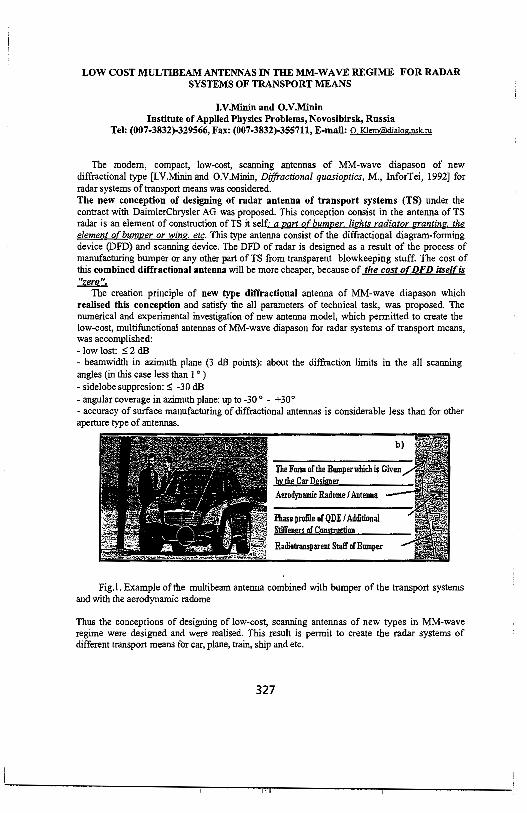
LOW COST MOL TIBEAM ANTENNAS IN THE MM-WA VE REGIME FOR RADAR SYSTEMS OF TRANSPORT MEANS
I.V.Minin and O.V.Minin Institute of Applied Physics Problems, Novosibirsk, Russia
Tel: (007-3832)-329566, Fax: (007-3832)-355711, E-mail: 0 [email protected]
The modem, compact, low-cost, scanning antennas of MM-wave diapason of new diffractional type [I.V.Minin and O.V.Minin, Diffractional quasioptics, M., InforTei, 1992] for radar systems of transport means was considered. The new conception of designing of radar antenna of transport systems (TS) under the contract with DaimlerChrysler AG was proposed. This conception consist in the antenna of TS radar is an element of construction of TS it self: a part of bumper. lights radiator e:rantin'?, the element of bumper or wing. etc. This type antenna consist of the diffractional diagram-forming device (DFD) and scanning device. The DFD of radar is designed as a result of the process of manufacturing bumper or any other part of TS from transparent blowkeeping stuff. The cost of this combined diffractional antenna will be more cheaper, because of the cost ofDFD itself is "zero".
The creation principle of new type diffractional antenna of MM-wave diapason which realised this conception and satisfy the all parameters of technical task, was proposed. The numerical and experimental investigation of new antenna model, which permitted to create the low-cost, multifunctional antennas of MM-wave diapason for radar systems of transport means, was accomplished: - low lost: :,; 2 dB - beamwidth in azimuth plane (3 dB points): about the diffraction limits in the all scanning angles (in this case less than I O
)
- sidelobe suppresion: :,; -30 dB - angular coverage in azimuth plane: up to -30 ° - +30° - accuracy of surface manufacturing of diffractional antennas is considerable less than for other aperture type ofantennas.
The Form of the Bumpenmichis Given by the Car Designer Aerodynamic Radome / Antenna
Phase profile of QDE / Additional Stiffeners of Construction
Radiotransparent Stuff ofBumper
Fig.1. Example of the multibeam antenna combined with bumper of the transport systems and with the aerodynamic radome
Thus the conceptions of designing of low-cost, scanning antennas of new types in MM-wave regime were designed and were realised. This result is permit to create the radar systems of different transport means for car, plane, train, ship and etc.
327

THIS PAGE INTENTIONALLY LEFT BLANK
328

Thursday Afternoon URSI B Session 110 Coral Room B
NUMERICAL METHODS: HYBRID TECHNIQUES Session Chairs: T. Cwik and D. Riley
1:15 Opening Remarks
Page
1:20 Radiated field coupling into enclosures via apertures, Z. Pantie-Tanner, F. Gisin, M 330 Harrison, W. Fung, San Francisco State University
1 :40 A hybrid FEM approach to intrasystem EMC analysis, J. Balbastre, L. Nuno, 331 Universidad Politecnica de Valencia, Italy
2:00 Application of A WE in conjunction with SWITCH code, C. Reddy, C. Crockwell, F. 332 Beck, S. Bindiganavale, M Sancer, Hampton University
2:20 Efficiency, accuracy and stability of hybridized finite-elements, finite-volumes, and 333 finite-differences in transient electromagnetic simulations, D. Riley, Sandia National Laboratories
2:40 Iterative solution of wideband scattering from arl>itrarily-shaped PEC targets and 334 dielectric BOR's over a half space, A. Sullivan, L. Carin, Duke University
3:00 Application of the integral equation-asymptotic phase method to three-dimensional 335 scattering, K Aberegg, A. Peterson, ERIM International
3:20 Solution of the Helmhotz equation using the Laplace solution, T. Sarkar, Syracuse 336 University, USA
3:40 3D-2D combined FEM analysis of guiding structure transitions, G. Biffi-Gentili, E. 337 Martini, S. Selleri, G. Pelosi, University of Florence
4:00 Electromagnetic sounding of cavities in layered lossy media, V. Veremey, J. Ma, W. 338 Yu, R. Mittra, Pennsylvania State University
4:20 A method for incorporating perfect conductors in to the PITD scattering method, J. 339 Miller*, R. Nevels, Texas A&M University
4:40 Methods for incorporating high dielectric constant scatters into the path integral time- 340 domain method, J. Miller*, R. Nevels, Texas A&M University, USA.
329

RADIATED FIELD COUPLING INTO ENCLOSURES VIA APERTURES
Z. Pantie-Tanner*, Franz Gisin, Monica Harrison, Wilson Fung San Francisco State University
San Francisco, CA 94132 ([email protected])
Electromagnetic fields produced by high powered transmitters can cause significant susceptibility problems in the digital and analog circuits used in the computer, airline and automotive industries. One of the main mechanisms of coupling is through enclosure apertures. Radiation of electromagnetic fields due to sources inside enclosures coupling through apertures have been extensively studied (J.D Turner, et al, "Characterization of the Shielding Effectiveness of Equipment Cabinets Containing Apertures", EMC '96 Roma, September 1996; S. M. Radu, et al, "Investigation of Internal Partitioning in Metallic Enclosures for EM! Control"; and Shinji Tanabe, et al, "3D-FEM Analysis for Shielding Effects of a Metallic Enclosure with Apertures", 1996 IEEE International Symposium on EMC). The reverse, however, where plane waves penetrates an enclosure via the same apertures that radiate has not received as much attention. In this paper we address the coupling problem from the point of view of susceptibility instead of emissions.
Enclosures that house electronic circuits generally have apertures (slots between two adjacent metallic pieces, cooling vents, etc.) that become more transparent as the frequency increases. Once the electromagnetic waves penetrate an aperture, it can excite standing waves in the cavities surrounding the electronic circuits. These mechanisms can produce high levels of induced voltages and currents that cause the circuits to malfunction.
In this paper, several examples of small desktop and handheld electronic devices are modeled using the FDTD method to show how these effects can cause sensitive electronic circuits to malfunction. A novel broadband modulated Gaussian pulse was used as the source. The broadband nature of the source allowed us to obtain accurate modeling information from fairly low frequencies up to approximately 15 GHz using only one time sweep.
Three separate analysis were performed. The first study modeled the effects of an isolated aperture. A simple model where the aperture was placed in an infinite ground plane was used. An electrically small source (to simulate a point source) was placed on one side of the aperture, while several field probes that measured E., Ey, E,, H,, Hy, and H., were placed on the other side. The frequency domain magnitude of the field probes , FFT(probe) were divided by the frequency domain magnitude of the source, FFT(source), resulting in a simple "transfer function" metric that could be used to compare the relative effectiveness of different shaped apertures. In the second study, the apertures were added to differently shaped enclosures. For this case, the source was modeled as a plane wave impinging on the enclosure. The E and H-field probes were placed inside the enclosure. In this case, the field probes values included both aperture and enclosure cavity resonances. In the third study, several simple planar circuits on printed circuit boards located inside the enclosure were added to the model. The induced voltage and current were computed. Comparing the results from the these three studies, the effects of the two field coupling mechanisms (aperture coupling and/or cavityresonances) on the induced voltages and currents in the printed circuit board circuits could be evaluated.
330

A HYBRID FEM APPROACH TO INTRASYSTEM EMC ANALYSIS
Juan V. Balbastre* and L. Nuiio Department of Commnunications.
Polyechnique University of Valencia {Spain)
Electronic systems are enclosed in some kind of envelope or shield, in order to protect them from their environment. However, those envelopes will modify the electromagnetic behavior of a given system, thus affecting its whole performance. In the present work, we have adapted a previously developed 2D technique (J. V. Balbastre, L. Nuiio and M. Ferrando, IEEE Trans. Electromagn. Compal. 40, 47-54, 1998) for solving intrasystem z-invariant EMC problems, like that shown in figure 1. The proposed solution is based in a multimodal scattering matrix, obtained using the Finite Element Method and the modal expansion of the solution in terms of cylindrical harmonics inside the boundaries p
1 and p,. Then, once the structure has been
characterised by its scattering matrix, and the cylindrical-wave spectrum of the interferent signal is identified, the total electromagnetic field can be computed inside the structure.
This procedure has been applied to compute the perturbation introduced in the cavity on the right when the line source is placed on the z-axis (see figure !). In figure 2 we present the total electric field in the victim cavity when the operating frequency matches that of the cavity TM21
mode. However, the TMi2 is not excited, although it has the same resonant frequency. In fact, no mode with its field pattern vanishing along y=O is excited, as can be observed in figure 3, where we show the electric field inside the cavity when the operating frequency corresponds to that of TM22 mode. In this case, the maximum E field strength inside the cavity is O.Q3 Vim, instead the 1.07 Vim achieved in the TM21 case. All those results correspond to no resonant slots (the slot length is not a multiple of the half-wavelength). If the frequency is fixed to TM22
resonant frequency, but the slot length is modified in order to be now resonant, a significant interferent field is coupled into the victim cavity. This can be seen in figure 4, where the maximum E field inside the cavity is 1.86 Vim. Thus, we can state that the amplitude of the perturbation depends on both the cavity and the slot resonant frequencies.
y
':--bf),. a'
X P2
figure 1 figure 2
figure 3 figure 4
331

Application of AWE in Conjunction with SWITCH Code
C. J. Reddy* C.R.Cockrell & EB.Beck S.Bindiganavale & M. Sancer Hampton University NASA Langley Research Ctr. Northrop Grumman Corp. Hampton VA 23668 Hampton VA 23681 Pico Rivera, CA 90660
ABSTRACT
The SWITCH code with hybrid Finite Element and Method of Moments using curvilinear basis functions to reduce the number of unknowns is a powerful tool to calculate RCS of arbitrarily shaped objects. One of the disadvantages of this code is the computational cost involved in obtaining solutions over a frequency range as computations are to be repeated for each frequency over a frequency range. In this paper, an application of Asymptotic Waveform Evaluation
(AWE) with Pade approximation to SWITCH code is presented. This approach was validated previously with triangular/tetrahedral element based hybrid FEM/ MoM codes developed at NASA Langley Research Center ( Cockrell et al, NASA TM 110292,1996, Reddy et al, NASA CR 97-206261, 1997). The AWE technique is first applied to Electric Field Integral Equation (EFIE) part of the SWITCH code with curvilinear quadrilateral elements. Figure 1 shows RCS of a PEC ogive
(EMCC benchmark) calculated using AWE technique with Pade approximation at frequenciesf01 andf02 . Advantage of AWE technique is that system calculations
need to be done only at J01 and J02. The results are compared with calculations
done by SWITCH at 60 individual points. The AWE technique with 600 points of frequency extrapolation required 1104 secs of CPU time, whereas 60 points of SWITCH individual calculations required around 8296 secs of CPU time on an SGI, Indigo 2 machine. Currently we are extending the implementation of A WE to the RCS calculations of the cavity-backed apertures. More numerical examples will be presented at the conference.
f25 ~-30 U) (.) C: -35
-40
=-=-: AWE_SWITCH(S/4) / • SWITCH •• '-----------'_, ...
_.,·" .............
.! ' .· .,.
332
., ., ., .,
.! "
100
80
60
., 20 i 0 -3l ·20i ... -40
-60
-80
·100

Efficiency, Accuracy, and Stability of Hybridized Finite-Elements, f.. nite-Volumes, and Finite-Differences in Transient
Electromagnetic Simulations
Douglas J. Riley Electromagnetics and Plasma Physics Analysis Department
Sandia National Laboratories Albuquerque, New Mexico 87185-1152
The hybridization of finite-elements, finite-volumes, and finite-differences for tra nsient applications is examined in this paper. Edge-based finite-elements provide geometric flexibility, are inherently stable, and accurately model interior boundary conditions. On tetrahedral-element grids, conditionally stable implementations based on both Whitney -1 and -2 forms, as well as unconditionally stable impl ementations based on Whitney-1 forms are well known. Edge-based functions for other cell types are also available. Finite-element schemes are generally unstru ctured and implicit, and although they can be solved fairly efficiently using precond itioned conjugate-gradient methods, their efficiency is lower than structured-grid finite differences.
Finite-volume methods based on offset, or dual, grids represent a generalization of the relatively simple finite-difference time-domain method. A variety of finite-volume algorithms have been proposed, each with varying degrees of success related to the element type. Because of their explicit nature and the ease of generalization to a rbitrary cell types, finite-volume methods are appealing; however, it appears that the fundamental algorithms are typically unstable in the late time for all cell types other than rectangular hexahedral elements. Various stabilization schemes of the basic algorithms have been proposed. These include modifications to the timeadvancement to provide high-frequency dissipation, and forcing symmetry in the projection matrices. Both of these methods have been found to be successful for certain cell types and geometries.
The hybridization of 3D finite-volume methods and structured-grid finite-differences has been researched for many years. More recently, 3D finite-elements have also been combined with the finite-difference time-domain method. Although these hybrid schemes can provide high accuracy and efficiency, they both have been doc umented to suffer from weak instability, which may or may not be an issue depending on the geometry under investigation and/or the discretiz ~tion ..
This paper provides a detailed look into finite-elements and finite-volumes, and their hybridization with the rectilinear finite-difference time-domain method. Through the judicious use of dual-grid finite-volume methods at the interface between finiteelements and finite-differences, both grid reflection errors and late-time stability can be improved. However, a definitive solution to stability remains open at this time.
333

I I I
i
I
' I
4
I
Electromagnetic Sounding of Cavities in Layered Lossy Media
Vladimir Veremey, Ji-Fu Ma, Wenhua Yu and Raj Mittra Electromagnetic Communication Research Laboratory
Pennsylvania State University, 319 Electrical Engineering East University Park, PA 16802-2705
e-mail: [email protected] or [email protected]
Location of inhomogeneities in a stratified medium is a very important problem because it finds a wide variety of applications in remote sensing, geophysical prospecting and non-destructive testing. This has prompted the development of a plethora of techniques for the analysis of the electromagnetic properties of the earth under the assumption that it is a layered dielectric structure, and that the objects to be located are ore bodies in rocks.
In the present paper we consider a somewhat different problem of electromagnetic sounding rather than that of the exploration of highly conductive ore bodies embedded in a rocky medium, that rely upon electromagnetic induction for their detection. In contrast, the approach presented in this paper has been developed for the exploration of buried cavities filled with materials such as air, whose conductivity is negligibly small. In addition, the conductivity of the surrounding medium can be very high and, hence, we consider the situation where the penetration of the electromagnetic waves is extremely shallow at high frequencies. One consequence of this is that, in order to locate the cavities that are embedded deep in a lossy ground, it becomes necessary to utilize very low frequencies, e.g., VLF and ELF, for the sensing. However, the modeling the buried cavity problem becomes very difficult when the frequency is less than 1 kHz, if conventional numerical techniques,e.g., the Finite Difference (FD) (p.A. Newman and D.L. Alumbaugh Geophysical Prospectings, 43, 1021-1042, 1995), Finite Element (FE), or the Finite Difference Time Domain (FDTD) methods are employed for this purpose. To circumvent this problem, we propose a hybrid approach in this paper that combines the numerical methods with asymptotic extrapolation and Fast Fourier Transform techniques, to derive the solution to the problem in hand.
As the first step in this approach, we derive the Greens function for the layered media followed the Hertz potential approach, proposed by Felsen (L. Felsen and N. Marcuvitz, Radiation and Scattering of Waves, Prentice-Hall, Electrical Engineering Series, 1973), because it leads to a numerically convenient form.
Next, we construct an analytically explicit solution of a canonical problem,viz., that of scattering by a dielectric inclusion of spherical shape, and show that the field inside the sphere tends asymptotically to a constant in the low frequency limit. This enables us to extrapolate the field behavior to frequencies below the lower end of the numericallyviable limit for which we are able to carry out the computation by using one of the available numerical techniques.
Finally, we apply the extrapolation approach in this paper to the 3-D cavity problem and present numerical results that illustrate the efficiency of the method.
338

A Method for Incorporating Perfect Conductors into the PITD Scattering Method
J.A. Miller' and R.D. Nevels Department of Electrical Engineering
Texas A&M University College Station, TX 77843-3128
The Path Integral Time-Domain (PITD) method (R. Nevels, J. Miller, and R. Miller, "Rotation in Electromagnetic Field Equations: A Discussion, Interpretation and Application", AP-S/URSI International Symposium, Atlanta, Georgia, June 1998, p. 875-878) is a new electromagnetic field scattering technique. It is based on a Feynman path integral formulation, which results in a propagator solution to the time domain form of Maxwell's differential equations. The essence of the PITD method is that the present time electric and magnetic field components are first Fourier transformed into the spectral domain, then multiplied by a state transition matrix and finally inverse transformed back to the real space-time domain. This set of operations advances the field one time step. Although simple in principle, the PITD method has not proven successful when the scattering object is a perfect conductor. The difficulty centers on the manner in which the Fourier and inverse Fourier transforms are numerically implemented in the PITD algorithm. If a fast Fourier transform is used then some high frequency components become suppressed at each time step, which is manifest as an instability in the field calculation.
In this paper, we will present a procedure for incorporating a boundary condition for a PEC object residing in a loss_less homogeneous space into the PITD method. In theory, a boundary condition should not be necessary with this method. We will first discuss the numerical limitations that prevent direct application of the PITD method when a plane wave impinges on a PEC object. A technique for explicitly enforcing the Dirichlet boundary condition on the conductor will then be described. The subtlety of this boundary condition becomes apparent in two and three dimensional problems. In the rectangular lattice the incident electric and magnetic fields must be decomposed into components tangential and normal to the stair stepped surface of the scattering object. It will be shown that this method is simple and can be numerically implemented in a straightforward manner. Examples will be presented for a plane wave incident on a one-dimensional planar surface and a two-dimensional circular cylinder. The results will be compared with exact field solutions obtained from analytical equations.
339
Methods for Incorporating High Dielectric Constant Scatters into the Path Integral Time-Domain Method
R.D. Nevels* and J.A. Miller Department of Electrical Engineering
Texas A&M University College Station, TX 77843-3128
The Path Integral Time-Domain (PITD) method (RNevels, J. Miller, and R. Miller, "Rotation in Electromagnetic Field Equations: A Discussion, Interpretation and Application", AP-S/URSI International Symposium, Atlanta, Georgia, Junel998, p. 875-878) is a new electromagnetic field scattering technique based on a F eynrnan path integral. The path integral formulation yields a propagator solution to the time domain form of Maxwells differential equations. The PITD algorithm for implementing the path integral equations is as follows: !)The present time electric and magnetic field components are Fourier transformed into the spectral domain. 2)The spectral domain components are multiplied by a state transition matrix, accomplishing time stepping. 3 J[he resulting product is inverse transformed back to the real space-time domain. However, spurious errors arise when the electromagnetic field scatters from objects with a high dielectric constant. These errors can be traced to the state transition matrix. This matrix is composed of simple combinations ofsines and cosines. Because a numerical fast Fourier transform is used to approximate the Fourier transform in the path integral expression, each component of the transition matrix must form a full period in the numerical space. However, the period of the transition matrix depends on the dielectric constant of the region in which it is applied. If for example the numerical code is set up so that the components of the transition matrix form a complete period in air then the transition matrix components will typically not be symmetric in any of the non perfect conductin~catterers in that region.
In this paper, we will present several procedures of overcoming this difficulty. One approach is to map each dielectric region into one that produces transition matrix components that form a complete period for each dielectric in the scattering region. After the 3rd step in the above algorithm the spatial field components can then be mapped back into the original space by a simple interpolation procedure. A second approach is to increase the spectral frequency sample width. Again the result of the j algorithm step is mapped back to the original sample width space. The third approach is to use non-uniform fast Fourier transforms. This approach requires no interpolation or mapping. Results obtained with each of these methods will be compared with exact analytical solutions. Examples will include one-dimensional scattering from a slab and two-dimensional scattering by a circular dielectric cylinder, each excited by a plane wave incident field.
340

Thursday Afternoon URSI B SPECIAL SESSION Session 112 Convention Center Ballroom I
SPECIAL SESSION ON CONFORMAL ANTENNAS Session Chairs: L. Kempel and D. Werner
I: 15 Opening Remarks
Page
1:20 Conformal loadbearing antenna structures, S. Schneider*, J. Tenbarge, J. Tuss, Wright 342 Patterson AFB, USA
1:40 Advances in modeling conformal antennas on cylinders L. Kempel*, Michigan State 343 University, USA
2:00 Analysis and design of a cavity-backed log periodic array antenna, T. Durllam*, B. 344 Karr, G. Gothard, Harris Corporation, USA, C. Christodoulou, University of New Mexico, USA
2:20 A technique for analyzing cavity-backed conformal antennas mounted on arbitrarily- 345 shaped conducting bodies, D. Arakaki*, D. Werner, R. Mittta, Pennsylvania State University, USA
2:40 Fast hybrid finite element algorithms for conformal antenna analysis, J. Volakis, T. 346 Eiben, K. Sette!, L. Andersen, D. Filipovic, University of Michigan, USA ·
3:00 Break
3:20 Integrated antennas for advanced handset communication units: Miniaturization and 347 human interactions reductions, Y. Rahmat-Samii, University of California, Los Angeles, USA
3:40 Pattern synthesis of ARC antenna arrays with directional elements, K. Virga, 348 University of Arizona, USA
4:00 Modelling of a conformal high gain satellite antenna with full spherical coverage, D. 349 Loeffler, E. Gschwendtner, W. Wiesbeck, University of Karlsruhe, Germany
4:20 Full wave analysis of slotted elliptic waveguides, G. Amendola, G. Di Massa, 350 Universita' della Calabria, Italy, G. Mazzarella, Universita' di Cagliari, Italy
341

Conformal Loadbearing Antenna Structures
Stephen W. Schneider*, Joseph A. Tenbarge and JimTuss Air Force Research Laboratory
Wright Patterson Air Force Base Dayton,OH
As the demand for more sophisticated avionics has grown, so has the demand for RF antennas to support these functions. · A typical military aircraft has as many as sixty to seventy single function antennas located at various points on the vehicle. Hence, significant portions of the aircraft surface are dedicated to antennas, with many antennas competing for the locations that provide the maximum field of view and minimum electromagnetic interference. Traditionally, antennas designers developed and manufactured antennas for a specific function, then sold them to airframe maintainers to 'bolt on" or 'bolt in" to the aircraft structure. Mechanical/structural considerations often imposed size and placement constraints on the antenna resulting in a compromise of performance.
Under Air Force sponsorship, structures, material and antenna designers have pooled collective talents to develop a new high payoff aperture technology referred to as Conformal Loadbearing Antenna Structures (CLAS). Using this approach, traditional aperture antenna installations are replaced with a variety of structurally integrated antennas imbedded in the outer mold line of the host platform. The use structurally integrated antenna technology allows antennas of much larger size to be placed in locations heretofore unusable.
In this presentation, we will describe current advancements in ConformalLoadbearing Antenna Structures. This presentation will focus on the design methodology and potential payoffs. Results will be shown and discussed.
342

Advances in Modeling Conformal Antennas on Cylinders
Leo C. Kempel* Electromagnetics Laboratory
Michigan State University East Lansing, MI
Significant research has been performed over the past ten years in applying the finite element-boundary integral (FE-BI) method to the problem of modeling conformal antennas. Toe principal reason for interest in the FE-BI as a means of predicting conformal antenna performance is its ability to model complex antenna shapes with inhomogeneous material properties.
Our research group, as well as colleagues at other organizations, has found that achieving acceptable results for such antennas require more than blindly using general purpose computer programs. Optimized numerical solutions are often required to achieve acceptable results. Researchers at Michigan State have recently developed FEBI tools for analyzing the radiation properties of complex antennas such as the circular log-periodic antenna shown inFigure I.
8-ann, 8-section LPA Phase Plot [30 GHz, 8= 30} 180.0 r.....-o-.-.,~.,.,-.~....-,7""""-r--....,..,-.,.,..,
Aagle(4.deg]
Figure I. Log-periodic antenna and far-field phase response vs. angle-of-arrival.
The phase of the transmitted signal is shown for modes 1 and 2. The difference between these two mode phases indicates the angle-of-arrival. Note that for mode 1 the slope of the phase response is one while for mode 2 the slope is two.
We will present our latest findings for modeling such complex antennas as a continuation of the material presented at last year's meeting. This presentation will focus on new solution methodologies, inclusion of significant antenna curvature in the results, and comparisons with measured data.
343

Analysis and Design of a Cavity-Backed Log Periodic Array Antenna
T.E. Durham, B.A. Karr, G.K. Gothard Harris Corporation, P.O. Box 94000, Melbourne, FL 32902-9400
and C.G. Christodoulou
Electrical Engineering Department, University of New Mexico, Albuquerque, NM 87131-1356
A detailed analysis has been developed for a particular class of cavity-backed Jog periodic (CBLP} array antennas. These antennas are useful for very broad bandwidth applications. In the CBLP antenna, a Jog periodic array of elements is mounted in a circular cavity having a conical bottom. The cavity is loaded with dielectric to reduce the physical size of the overall antenna. The antenna is modeled using a previously developed method of moments (MoM) solution for structures with partial rotational symmetry (Durham and Christodoulou, IEEE Antennas and Propagation, September 1992, pp. 1061-1067). In this solution the rotationally symmetric portion of the structure can be perfectly conducting and/or dielectric. The remainder of the structure consists of multiple arbitrarily shaped conducting objects. For the cavity-backed antenna, taking advantage of the rotational symmetry of the cavity and dielectric regions results in a more computationally efficient solution than would otherwise be possible.
Current distributions on the radiating elements as well as far field patterns have been generated based on the MoM solution. An extensive set of measurements has also been obtained on a CBLP antenna. In this presentation we will compare the predicted and measured far field magnitude and phase patterns. Very good agreement has been obtained for both magnitude and phase. The usefulness of current visualization in designing a CBLP antenna will also be discussed. Current plots have been used to optimize the cone angle of the cavity bottom in order to suppress higher order harmonics that can have deleterious effects on antenna performance in some applications.
344
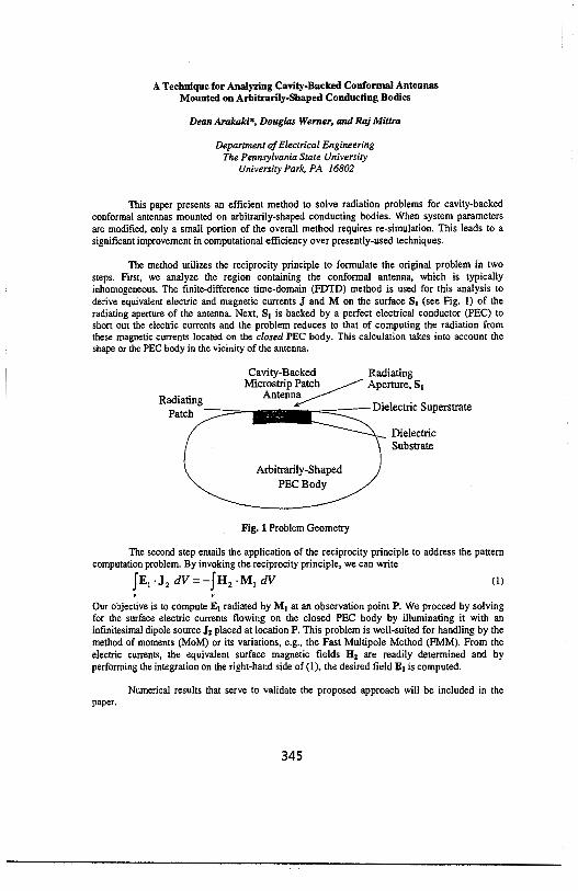
A Technique for Analyzing Cavity-Backed Conformal Antennas Mounted on Arbitrarily-Shaped Conducting Bodies
Dean Arakaki*, Douglas Werner, and Raj Mittra
Department of Electrical Engineering The Pennsylvania State University
University Park, PA 16802
This paper presents an efficient method to solve radiation problems for cavity-backed conformal antennas mounted on arbitrarily-shaped conducting bodies. When system parameters are modified, only a small portion of the overall method requires re-simulation. This leads to a significant improvement in computational efficiency over presently-used techniques.
The method utilizes the reciprocity principle to formulate the original problem in two steps. First, we analyze the region containing the conformal antenna, which is typically inhomogeneous. The finite-difference time-domain (FDTD) method is used for this analysis to derive equivalent electric and magnetic currents J and M on the surface S1 (see Fig. 1) of the radiating aperture of the antenna. Next, S1 is backed by a perfect electrical conductor (PEC) to short out the electric currents and the problem reduces to that of computing the radiation from these magnetic currents located on the closed PEC body. This calculation takes into account the shape or the PEC body in the vicinity of the antenna.
Cavity-Backed Radiating Microstrip Patch ~ Aperture, S1
Radiatin Antenn~ . . Patch g - D1electnc Superstrate
Arbitrarily-Shaped
PECBody
Fig. 1 Problem Geometry
Dielectric Substrate
The second step entails the application of the reciprocity principle to address the pattern computation problem. By invoking the reciprocity principle, we can write
JE1 ·J2 dV=-fH 2 ·M1 dV (1)
Our objective is to compute E1 radiated by M1 at an observation point P. We proceed by solving for the surface electric currents flowing on the closed PEC body by illuminating it with an infinitesimal dipole source J2 placed at location P. This problem is well-suited for handling by the method of moments (MoM) or its variations, e.g., the Fast Multipole Method (FMM). From the electric currents, the equivalent surface magnetic fields H2 are readily determined and by performing the integration on the right-hand side of(!), the desired field E1 is computed.
Numerical results that serve to validate the proposed approach will be included in the
345

Fast Hybrid Finite Element Algorithms for Conformal Antenna Analysis
J. L. Volakis, T. F. Eibert, K. Sertel, L. S. Andersen and D.S. Filipovic Radiation Laboratory
Electrical Engineering and Computer Science Department The University of Michigan
1301 Beal Ave Ann Arbor, MI 48109-2122, USA
Email: [email protected] FAX: 1-734-647-2106
Hybrid finite element-boundary integral (FE-BI) methods have found success for the analysis of conformal antennas and arrays, often recessed in a vehicle's skin. For the most part, previous emphasis of the FE-BI methods has been on single element analysis with particular emphasis on multilayered structures. In this paper, we will present several recent upgrades of the FE-BI with particular emphasis on periodic array analysis. The following topics will be covered
1. Fast integral algorithms for mesh truncation Three fast methods will be examined/presented for finite and infinite array applications. The two popular methods (fast multipole, adaptive integral methods)can be implemented to realize up to O(NlogN) CPU and memory. However, each method has advantages when dealing with specific array configurations. For periodic arrays, a new method will be introduced, referred to as the advanced spectral domain method, to reduce the CPU and memory requirements down toaN, where o: is a constant. We note that this holds even for small values ofN (less than 1000).The performance of this approach will be compared with other fast methods, particularly when dealing with multilayered configurations.
2. Finite Arrays: For large finite arrays and frequency selective surfaces, hybrid techniques will be presented to efficiently treat such apertures in the presence of multi-layered structures or treatments.
3. Hierarchical Elements Higher order or multi-resolution elements are often used for better accuracy in regions associated with rapidly varying fields. However, they also lead to worse matrix condition numbers. To overcome this issu~ we have employed a new class of hierarchical multi-resolution elements which can be used selectively over the radiating edges of the antenna/array element. We will demonstrate the efficiency and improved accuracy of this approach.
4. Platform Interactions: When installed on platforms, antennas interact with the nearby structures, thus, giving rise to patterns distortions and scattering contributions. We will discuss techniques for incorporating antenna effects into standard moment method or high frequency methods.
346

Integrated Antennas for Advanced Handset Communications Units: Miniaturization and Human Interactions Reductions
Y. Rahmat-Samii Department of Electrical Engineering University of California, Los Angeles
Los Angeles, CA 90095-1594 [email protected]
The recent market evaluations and projections point to a continuing growth in popularity of personal terrestrial and satellite communications systems. Among the diversified components involved in the operation of these systems, handset units are perhaps the most visible part of the system that must be designed to satisfy user needs. Design issues range from the esthetic look of the unit to health considerations and antenna performance. Depending on the user's sophistication and operational needs, it is projected that a wide variety of designs will be used. As has been shown (Jensen and Rahmat-Samii, IEEE Proceedings, Jan. 1995), for a typical monopol antenna, approximately 50% of the total radiated power are absorbed in the biological tissues. The implications of this absorption are the reduction of the performance efficiency, high specific absorption rate (SAR) and reduction of the battery life. Any improvements in the antenna design are clearly of interest and are the topic of intense research.
The practical considerations for the design of handset antennas are the following: I) impedance match and bandwidth, 2) biological tissue effect on the input impedance and radiation pattern, 3) antenna gain, 4) antenna polarization, 5) power absorption in the human biological tissue, 6) antenna diversity performance to minimize the signal fading, etc. This presentation will highlight some of the recent progress in meeting these objectives. In particular, characteristics of integrated back-mounted antennas will be presented. Utilization of high dielectric material with external perforation in order to reduce the effects of the surface waves and to also isolate the antenna from the handset unit will be discussed. Additionally, by mounting the miniaturized antenna in the back of the handset, reduction of the energy absorption by the biological tissue is also observed. The concept of residing antennas on PMC-type material will be also evaluated. The machinery of the Finite Difference Time Domain (FDTD) and Eigenfunction Expansion Method (EEM) are used to assess the performance characteristics of these antennas in various operational situations. Representative data are presented for the S 11, antenna patterns with and without the presence of the users head and hand, near field characteristics, and SAR values.
347

PATTERN SYNTHESIS OF ARC ANTENNA ARRAYS WITH DIRECTIONAL ELEMENTS
Kathleen L. Virga Department of Electrical and Computer Engineering
University of Arizona, Tucson AZ 85721-0104
The geometry of arc antenna arrays precludes the use of pattern synthesis techniques commonly used for planar arrays. In arc antenna arrays, the element pattern and array factor cannot be separated since the pattern function depends upon the element pattern in the particular direction of interest. The individual pattern of each radiating element depends upon the location of the element in the array and is different from all of the others. Another consideration is that at wide observation angles, some of the edge elements are blocked by the internal electronics and thus a "line of sight" factor must be included as part of the element factor. The element patterns, in many cases, will be different from the simple element patterns of dipole antennas that have often been used in arc antenna array modeling.
A multitude of distribution functions can be obtained when the arc array allows for independent phase and amplitude control of each element. To obtain the optimal distribution functions given a set of pattern and/or distribution constraints, a design program based upon Genetic Algorithms (GA) is used. GA optimization methods are particularly useful for multi-variable design problems that are highly constrained and thus difficult to solve with local optimization techniques. In this case, GAs are used to optimize the array amplitude and phase coefficients given the array geometry and the physical element factor data as a function of angle. The element factor data is obtained from simulations and measurements of Vivaldi and Dual Exponentially Tapered Slot Antennas [Greenberg, et. al. 1999 Antennas and Propagation Society Digest].
Results for several pattern cases will be discussed. These cases include patterns for optimum directivity, optimum directivity with a constraint on the maximum sidelobe level, and optimum directivity with a constraint of discrete (or quantized) phase and amplitude values. Comparisons of the effects of arc sector size, element spacing, directionality of elements, and distribution constraints on pattern performance will be given. The output parameters of interest include the array phase and amplitude distribution as well as the radiation pattern characteristics. A comparison of the robustness of antenna performance for a particular array due to amplitude and phase quantization and small random errors will also be discussed.
348

Modelling of a Conformal High Gain Satellite Antenna with Full Spherical Coverage
Summary
*D. Loffler, E. Gschwendtner, W. Wiesbeck Institutfilr Hochstfrequenztechnik und Elektronik,
University of Karlsruhe, KaiserstraBe 12, 76128 Karlsruhe, Germany
The satellite Hipparcos (High Precision Parallax Collecting Satellite), launched by ESA in 1989, measured the positions, parallaxes and proper motions of about 120,000 stars. The space science mission DIVA (S. Roser et al., "DIVA - a small satellite for global astrometry and photometry", IAU General Assembly, Kyoto, Japan, 1998, to be printed in Highlights of Astronomy) is intended to be a successor of Hipparcos and a scientific and technological precursor for major interferometric science satellites planned by ESA (GAIA: Global Astrometric Interferometer for Astrophysics, ESA's Horizon 2000+ Astrometry program) and NASA (SIM: Space Interferometry Mission, scheduled launch June 2005). Like some other small spinning scientific satellites, DIV A has a fixed position of the spinning axis with respect to the sun. Due to this alignment, the earth can appear in any angular position relative to the satellite, which causes the need for an antenna with full spherical coverage to maintain a permanent link to the control facilities on earth. Up to now this coverage usually was achieved by the use of ordinary TT&Cantennas, as they are utilized on communication satellites for telemetry, tracing and command. For this control application there is no need for high-data-rate communication, so this antenna neither offers high bandwidth nor high gain. The low gain of this antenna type results in a bad signal-to-noise ratio (SNR) at the receiving antenna on the earth. As a consequence the data rate is limited to small values. In scientific missions with a high amount of data needed to be transferred to the earth, the use of these antennas results in a bottle neck in the data link and lowers the efficiency of the scientific mission itself. An increase in SNR at the receiving antenna needs an increase in signal strength because the noise figure of commercially used receiving antennas on the earth is already extremely low and cannot be lowered further without major technical effort. Hence the gain of the transmitting antenna on the satellite has to be increased. In this contribution the design and simulation of a broadband conformal antenna concept is presented which yields an average gain of 7 .6 dBi over the full sphere for the antenna on the satellite. The antenna consists of 26 elements which are located at different positions on the surface of the satellite. By using the knowledge of the earth's angular position from the satellite's navigation system, the element pointing best towards the earth is used for the link. Technically this problem is solved by using a low-loss switching matrix. Slot spirals are used as single elements. The simulations are carried out using the method of moments / UTD hybridization of the FEKO software (U. Jakobus,et al., "Recent progress on moment method/ UTD hybridization", Proc. of the Progress in Electromagnetics Research Symposium (PIERS), Nantes, p. 459, July 1998). Using this new antenna there appears to be no limitation in the bandwidth of the data link due to the transmitting antenna, because the bandwidth of the used slot spiral can easily be one octave. Besides the large bandwidth, the pure circular polarisation is a major advantage of the spiral antenna. A usable data rate of 1.2 Mbit/s having a BER of 10-5 can be achieved using this switched conformal array antenna with an RF-bandwidth of 2 MHz in S-band.
349

Full Wave Analysis of Slotted Elliptic Waveguides
G. Amendola*, G. Di Massa*, G. Mazzarella+ *Dipartimento di Elettronica, Informatica e Sistemistica, Universita' della Calabria,
Rende, Italy. E-mail: [email protected] +Dipartimento di Ingegneria Elettrica ed Elettronica, Universita' di Cagliari, Piazza
D'Armi, 09123 Cagliari Italy E-mail [email protected]
Conformal antennas are an attractive solution in aereospace applications where antenna systems that cause the smallest possible perturbation to the aereodynamics of the aircrafts are required. During the years, researchers have studied slot and microstrip antennas on a number of canonical surface, namely spheres, circular cylinders and cones. This to give the designers the possibility to choose the surface that better fit the part of the fuselage of aircrafts where the antenna has to be installed. In this work, the class of surface analysed up to now is extended by considering a slot cut on an elliptic waveguide. The elliptic cylindrical system is particularly suited to model surface with a variable radius of curvature such as wings and tails of aircrafts. The analysis of the electric characteristics of a slot cut on a conducting elliptic cylindrical surface has been already presented (Wait, J.R., J. Appl. Phys, vol. 21, no. 4, pp. 458-463, April 1955) and recently revisited by one of the authors (Amendola, G., "Application of Mathieu functions to the analysis of radiators conformal to elliptic cylindrical surfaces" submitted for publication to Journal of Electromagnetic Waves and Applications) but, to the best of the knowledge of the authors, the full wave analysis of the slotted elliptic waveguide has never been presented. In this work a MoM solution, based on the application of the equivalence principle, will be proposed. The slot is modeled with equivalent distribution of magnetic currents and the following integral euqation is set up:
< a;,.,M. > + < G~,Ms >= H; (1)
where G;,. and G~ are the dyadic magnetic Green's functions for the waveguide and the outer region, respectively, 1VJ5 is the unkown magnetic current on the slot and H; is incident field in the waveguide. The unknown magnetic currents are expanded in terms of a suitable set of expansion functions(Amendola, G., see previous reference) and then the integral equation is solved with the application of a Galerkin procedure. As results, the slot scattering matrix, equivalent circuit and current distribution can be computed as functions of the slot position and of eccentricity of the section of the waveguide. Furthermore the extension to the case of a thick slot, modeled as an elliptic-cylindrical sectorial cavity, will be discussed.
350

URSI B Session 114 Thursday Afternoon
Koi
INVERSE SCATTERING Session Chairs: R. Stone and A. Boag Page
1:15 Opening Remarks
1 :20 Comparative analysis of the variational PDE and Born-type integral equation 352 approaches for optical diffusion tomography, J. Ye, K. Webb, Purdue University, USA
1 :40 Investigation of the K-pulse concept as applied to dielectric coated conducting 353 targets, G. Turhan-Sayan*, M. Kuzuoglu, Middle East Technical University, Turkey, D. Moffatt, Ohio State University, USA
2:00 Electromagnetic source imaging using superluminal cylindrical modes, M. Morgan, 354 Naval Postgraduate School, USA
2:20 Inverse scattering from electrically large regions via a hybrid linear-nonlinear 355 algorithm, B. Rao*, L. Carin, Duke Univeisity, USA
351
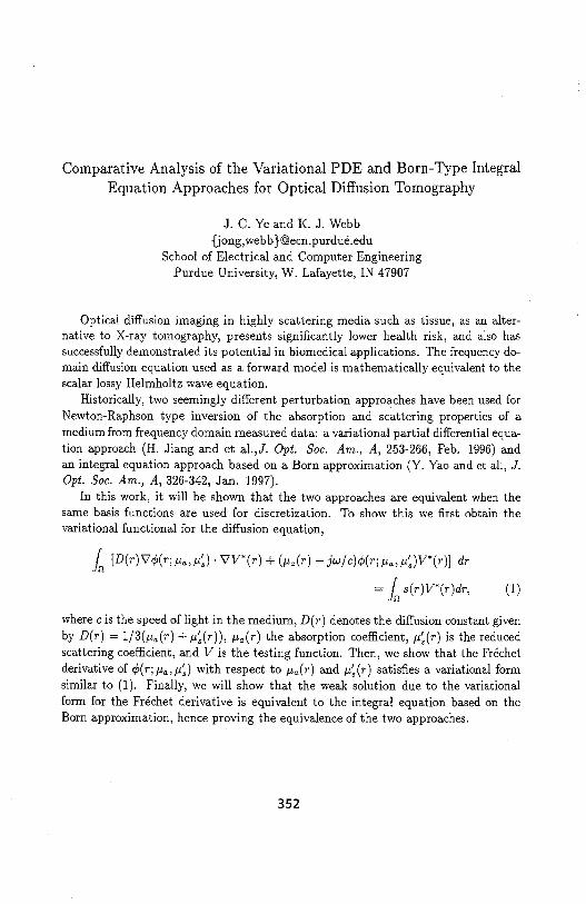
Comparative Analysis of the Variational PDE and Born-Type Integral Equation Approaches for Optical Diffusion Tomography
J. C. Ye and K. J. Webb {jong, webb }@ecn.purdue.edu
School of Electrical and Computer Engineering Purdue University, W. Lafayette, IN 47907
Optical diffusion imaging in highly scattering media such as tissue, as an alternative to X-ray tomography, presents significantly lower health risk, and also has successfully demonstrated its potential in biomedical applications. The frequency domain diffusion equation used as a forward model is mathematically equivalent to the scalar lossy Helmholtz wave equation.
Historically, two seemingly different perturbation approaches have been used for Newton-Raphson type inversion of the absorption and scattering properties of a medium from frequency domain measured data: a variational partial differential equation approach (H. Jiang and et al.,J. Opt. Soc. Am., A, 253-266, Feb. 1996) and an integral equation approach based on a Born approximation (Y. Yao and et al., J. Opt. Soc. Am., A, 326-342, Jan. 1997).
In this work, it will be shown that the two approaches are equivalent when the same basis functions are used for discretization. To show this we first obtain the variational functional for the diffusion equation,
1n [D(r)'vq,(r;µ.,µ:) · 'vV*(r) + (µa(r)-jw/c)q,(r;µa,µ:)V*(r)] dr
= Jn s(r)V*(r)dr, (1)
where c is the speed of light in the medium, D( r) denotes the diffusion constant given by D(r) = 1/3(µ.(r) + µ:(r)), µa(r) the absorption coefficient, µ:(r) is the reduced scattering coefficient, and V is the testing function. Then, we show that the Frechet derivative of q,(r;µa,µ:) with respect to µa(r) and µ:(r) satisfies a variational form similar to (1). Finally, we will show that the weak solution due to the variational form for the Frechet derivative is equivalent to the integral equation based on the Born approximation, hence proving the equivalence of the two approaches.
352

Investigation of the K-Pulse Concept as Applied to Dielectric Coated Conducting Targets
Gonill Turhan-Sayar(*) and Mustafa Kuzuo!lu
Middle East Technical University, Dept. of Electrical and Electronics Eng.,and TUBITAK-BILTEN (Information Technologies and Electronics Research Inst. of
the Turkish Scientific and Technical Research Council), Ankara, TURKEY
David L. Moffatt Professor Emeritus, The Ohio State University, ElectroScience Lab., · 43210 Columbus, Ohio, USA
Since the introduction of the "Kill pulse"concept by E. M. Kennaugh in early 80:, a considerable number of papers have been published on the applications of natural-response annihilation techniques in electromagnetic target identification. Considering the fact that many targets of practical importance (such as aircraft, missiles, ship, tanks, etc.) are basically made of conducting materials, the majority of these studies have been concentrated on the problems concerning perfectly conducting scatterers. Depending upon the target geometry, these conductors may behave either as a high-Q target (e.g. a straight thin conducting wire) or as a low-Q target (e.g. a conductor sphere) or behave somewhere in between. So far, different signal shaping techniques have been demonstrated to synthesize specially tailored pulse waveforms for various target geometries with the basic requirement that the Laplace transform zeros of a synthesized Kill pulse (or, K-pulse as also called) must coincide with the target' system poles within a specified operational bandwidth. As discussed by Kennaugh, this requirement is equivalent to the annihilation of the target' natural resonances in response to K-pulse excitation at all possible aspects and polarizations.
The purpose of this paper is to extend the applications of the K-pulse concept to dielectric scatterers and to dielectric coated conductors, in particular. The genetic algorithm techniques as well as the conventional optimization algorithms will be implemented for K-pulse synthesis. Also, the target poles will be estimated from the synthesized K-pulse waveforms. The effects of a dielectric coating on the natural resonances of a target will be studied using conducting spheres, dielectric spheres and dielectric coated conducting spheres as canonical targets. The pole loci as a function of coating permittivity and coating layer thickness will also be investigated.
353

ELECTROMAGNETIC SOURCE IMAGING USING SUPERLUMINAL CYLINDRICAL MODES
Michael A. Morgan ECE Department, Naval Postgraduate School 833 Dyer Road, Monterey, CA 93943-5121
Far-field performance for antennas or scatterers may be predicted through measurement of localized sources of radiated power on the structure. However, invasive measurements using current or field probes are likely to perturb the quantities being sought. An alternative to near-field probing is to ''back-propagate" measurements made from sufficiently large distances that the parameters of interest are not strongly influenced. Such inverse scattering approaches have been wrought with mathematical instabilities. Further,the halfwavelength diffraction limit provides reduced spatial resolution in defining localized sources based upon measurements made at far-field distances.
Recent discoveries employing supersonic modes to enhance acoustic imaging on cylindrical shells(E. G. Williams, J. Acoust. Soc. Am. 97 (1) Jan. 1995, 121-127) is translated into the realm of electromagnetics. Equivalent relationships are derived, using a kspace spectral decomposition, which relate field components between near-field and far-field locations. It is shown that onlysuperluminal modes, which satisfy ~zl < k and have faster-than-light axial propagation velocity, provide time-average radiated power. Examples are given to demonstrate enhanced image resolution of radiated power sources using superluminal mode back-propagation.
354
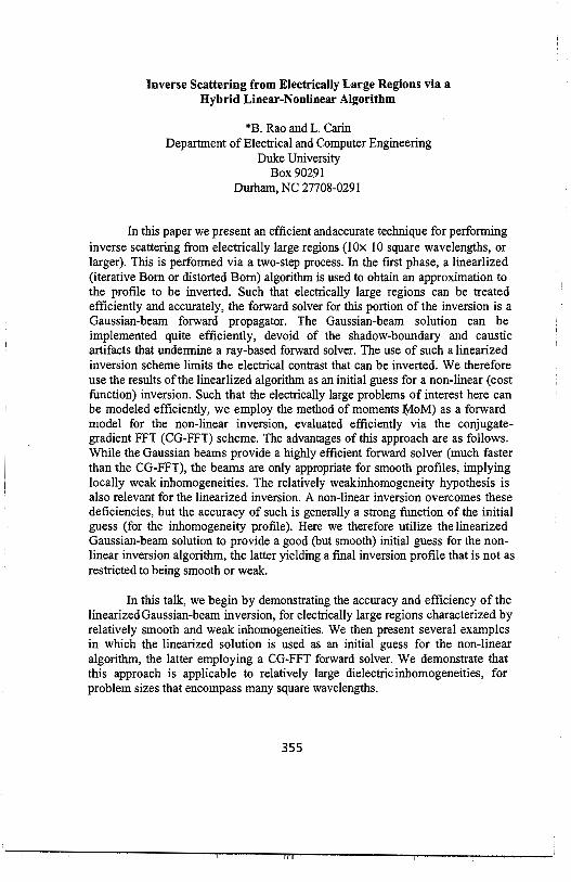
Inverse Scattering from Electrically Large Regions via a Hybrid Linear-Nonlinear Algorithm
*B. Rao and L. Carin Department of Electrical and Computer Engineering
Duke University Box 90291
Durham, NC 27708-0291
In this paper we present an efficient andaccurate technique for perfonning inverse scattering from electrically large regions (!Ox 10 square wavelengths, or larger). This is performed via a two-step process. In the first phase, a linearlized (iterative Born or distorted Born) algorithm is used to obtain an approximation to the profile to be inverted. Such that electrically large regions can be treated efficiently and accurately, the forward solver for this portion of the inversion is a Gaussian-beam forward propagator. The Gaussian-beam solution can be implemented quite efficiently, devoid of the shadow-boundary and caustic artifacts that undennine a ray-based forward solver. The use of such a linearized inversion scheme limits the electrical contrast that can be inverted. We therefore use the results of the linearlized algorithm as an initial guess for a non-linear (cost function) inversion. Such that the electrically large problems of interest here can be modeled efficiently, we employ the method of moments fy!oM) as a forward model for the non-linear inversion, evaluated efficiently via the conjugategradient FFT (CG-FFT) scheme. The advantages of this approach are as follows. While the Gaussian beams provide a highly efficient forward solver (much faster than the CG-FFT), the beams are only appropriate for smooth profiles, implying locally weak inhomogeneities. The relatively weakinhomogeneity hypothesis is also relevant for the linearized inversion. A non-linear inversion overcomes these deficiencies, but the accuracy of such is generally a strong function of the initial guess ( for the inhomogeneity profile). Here we therefore utilize the linearized Gaussian-beam solution to provide a good (but smooth) initial guess for the nonlinear inversion algorithm, the latter yielding a final inversion profile that is not as restricted to being smooth or weak.
In this talk, we begin by demonstrating the accuracy and efficiency of the linearized Gaussian-beam inversion, for electrically large regions characterized by relatively smooth and weak inhomogeneities. We then present several examples in which the linearized solution is used as an initial guess for the non-linear algorithm, the latter employing a CG-FFT forward solver. We demonstrate that this approach is applicable to relatively large dielectric inhomogeneities, for problem sizes that encompass many square wavelengths.
355

THIS PAGE IN1ENTIONALLY LEFT BLANK
356

Thursday Afternoon ORSI B Session 115 Convention Center Ballroom XI
ANTENNA ANALYSIS Session Chairs: A. Glisson and F. Niu Page
1:15 Opening Remarks
1:20 Finite element method applied to inhomogeneously loaded tapered profile monocone 358 antennas, M. Morgan, Naval Postgraduate School, USA
1 :40 Analysis and design of large antenna arrays using multi-grid FDTD and Floquet 359 boundary condition, Z. Yun, M Iskander*, University of Utah, USA, M. White, Raytheon, USA
2:00 FDTD analysis of the wide band feedline netwolk for .MMW antenna array 360 applications, L. Shen, McMaster University, Canada, C. Wu, LAE Corp., Canada, K. Wu, COM DEV, Canada, J. Litva, LAE Corp., Canada
2:20 Analysis, design process and correlation with measurements of a printed dipole 361 antenna using HP-HFSS, H. Delgado* Harris Corporation, USA, M. Thursby, Florida Institute of Technology, USA
2:40 The input impedance of an annular slot of art>itrary width, S. Zeilinger, Visteon 362 Automotive Systems, USA, D. Sengupta, University of Detroit Mercy, USA
3:00 Break
3:20 Resonant frequency and Q-factor computation for multi-region dielectric resonator 363 antenna structures, F. Chen, A. Glisson*, A. Kishk, University of Mississippi, USA
3:40 Circuit model, Q and bandwidths of electrtc antennas, F. Niu, Motorola Inc., USA 364
4:00 Transient analysis of cylindrical antennas in time-domain with non-harmonious net 365 using polynomial approximation for potential functions, L. Ololoska*, L. Janev, Macedonia
4:20 Application of the FDTD method in solving planar and confollllal patch antenna 366 problems, P. Shubitidze, R. Zartdze*, Tbilisi State University, Georgia, D. Economou, D. Kaklamani, N. Uzunoglu, National Technical University of Athens, Greece
357

FINITE ELEMENT METHOD APPLIED TO INHOMOGENEOUSLY LOADED
TAPERED PROFILE MONOCONE ANTENNAS
Michael A. Morgan ECE Department, Naval Postgraduate School 833 Dyer Road, Monterey, CA 93943-5121
A finite element algorithm is described for analysis of dielectrically loaded wideband monocone antennas having low-profile contoured surfaces for use on helicopters and fixed wing aircraft. The coupled azimuthal potential formulation (Morgan, IEEE Trans. Antennas Propagat, AP-36 , 1735-1743) is used to represent the field solution within the local region of the antenna structure, which may include inhomogeneous dielectric material. Dielectric loading is used to facilitate wideband impedance matching for an antenna structure which would be electrically small in free space. Trade-off between antenna performance over a selected frequency range and constraints in size and external profile shape is addressed.
1.s;~. ----~----------~
I 0.5~
i
I o' 0
358

Analysis and Design of Large Antenna Arrays Using Multi-Grid FDTD and Floquet Boundary Condition
Zhengqing Yun, Magdy F. Iskander* Electrical Engineering Department
University of Ut;h
Mikel J White Microwave Division
Raytheon/TI
The Finite-Difference Time-Domain (FDTD) method has been widely used in countless engineering applications. Recently there has been increasing interest in using FDTD in simulation, analysis, and characterization of periodic structures (P. Harms, R. Mittra and W. L. Ko, IEEE Trans. AP, 9, 1317-1324, 1994). Varying procedures have been proposed to implement the Floquet boundary condition in FDTD, and results for analyzing frequency selective surfaces and phased array antennas have been presented (G. Turner and C. Christodoulou, IEEE Symp. Dig., 1020-1023, 1998). In this paper we describe the implementation of the sine and cosine excitation function sources and the utilization of the Floquet boundary condition in the multi-grid FDTD code developed by our group (M. White, M. F. Iskander and Z. Huang, IEEE Trans. AP, 10, 1512-1517, 1997). Specifically, fields outside the periodical cell were determined using the phasor E- and H-field expressions at a symmetrically located FDTD cell within the periodical cell, together with the phase shift from the Floquet boundary condition. The new code was used to analyze the radiation characteristics and the input impedance values of a large antenna array taking into account the mutual coupling effects.
Numerical results illustrating the validity and accuracy of the developed code will be presented. Specifically, the radiation patterns of a 5 x 5 rectangular and a triangular antenna array were calculated and results were compared with available data obtained using FDTD only. In the triangle array geometries, equivalent rectangular geometries were developed and used in the FDTD analysis. It is also shown that while the implementation of the Floquet boundary condition in a regular FDTD code may provide sufficiently accurate results for an array of simple antennas, it is necessary to use the multi-grid FDTD code in analyzing antennas with complex feed structures.
359

FDTD Analysis of the Wide Band Feedline Network for MMW Antenna Ar~ay Applications
Linping Shen, Chen Wu*, Keli Wu** and John Litva*
Communication Research Laboratory McMaster University, Hamilton, Ontario L8S 4Kl, Canada
Email: [email protected] *LAE Cotp., Hamilton, Canada. **COM DEV, Cambridge, Canada
Abstract A wide band feedline network based on wilkinson power dividers and the
transition between input/element and the feed line is analyzed by the extended Finite Difference Time Domain(FDTD) method, which is used with a newly developed fast-speed scheme for implementing the non-ideal passive and active lumped elements. In this paper we present the analysis results and their experimental investigation of 1-2/4/32 feedline networks operating in the millimeter wave (MMW) band. Some design results were also verified by commercial CAD tools.
Summary
The endfire Linearly Tapered Slot Antenna(LTSA)(Chen Wu, Linping Shen, IEEE AP-S, 1998) has been widely used in many communication systems because of its wide band characteristics. In order to achieve high performance such as high gain, wide band and low sidelobe in MMW bands it is necessary to feed the LSTA by low loss feed lines. A wide band feedline network based on wilkinson power dividers and the transition between input/element and the feed line is analyzed by the extended Finite Difference time Domain(FDTD), which is used with a newly developed fast-speed scheme for implementing the non-ideal passive and active lumped elements.
The wide band feedline network consists of unequal-ratio wilkinson power dividers of an Inverted Microstrip Line(IML) and/or a suspended microstrip line(SML), the transition of input waveguide-to-IML/SML, and the coupling between IML/SML and array element. To obtain low sidelobe of antenna the output of the feedline network should be a cosine amplitude distribution. Because of usage of full wave analysis, considering the coupling between the feed lines and resistors, the new proposed feeding network has the advantage compared with the results designed by commercial tools.
360

"Analysis, Design Process and Correlation with Measurements of a Printed Dipole Antenna Using HP-HFSS"
Heriberto J. Delgado (*) Electromagnetic Analyst and Ph.D. Candidate at the Florida Institute of Technology Harris Corporation Electronic Systems Sector Government Communications Systems Division Post Office Box 91000, Mail Stop 5W-5840 Melbourne, Florida 32902-9100 Telephone: 1-407-727-4948, FAX: 1-407-729-2855 E-mail: "[email protected]"; "[email protected]"
Michael H. Thursby, Ph.D. Professor of Electrical Engineering Florida Institute of Technology Division of Electrical and Computer Science and Engineering Antenna Systems Laboratory (ASL) Melbourne, Florida 32901-6975 Telephone: 1-407-768-8000, X 7183 E-mail: "[email protected]"
ABSTRACT. A printed dipole antenna is modeled with HP HFSS, that stands for High Frequency Structure Simulator. HP-HFSS is a full wave electromagnetic simulator that uses the Finite Element Method. This tool provides a sophisticated CAD environment for the generation of the antenna geometry, and for the graphical display of output parameters such as input impedance and radiation patterns. In addition, HP-HFSS possesses adaptive mesh refinement features, that can adjust the mesh size locally, providing faster solutions and more accurate results. The measurement set-up consists of an HP-8720D vector network analyzer used for both input impedance and radiation pattern measurements, an antenna positioner, an IEEE 488 angular positioner controller, and a PC running a 944 Digital Pattern Recorder software (DPR). In order to increase the measurement dynamic range, WR90 waveguides are used to connect the dipole antenna to the network analyzer input port. The printed dipole and integrated microstrip balun arrangement are similar to the ones reported in ( G. S. Hilton, C. J. Railton, G. J. Ball, A. L. Hume and M. Dean, Ninth Int. Conf. on Antennas and Propagation, Eindhoven, Netherlands, vol. 1, pp. 72-75, April 1995) and ( B. Edward and D. Rees, Microwave Journal, pp. 339-344, May 1987). This antenna is printed on a duroid substrate using photo-etching techniques. The emphasis in this paper is given to the design process using HP-HFSS, where the antenna performance can be predicted accurately. The resulting antenna dimensional parameters are described in detail. The design frequency is 10 GHz. Both input impedance and radiation patterns are predicted with HP-HFSS and are compared to measured data. The input impedance is measured over a wide range of frequencies. The dipole is mounted on a circular ground plane for the far field radiation pattern measurements, which are performed at 10 GHz. Since the dipole is mounted on a finite ground plane, a scalloping, caused by edge diffraction, is present in the antenna pattern. The discrepancies between measured and predicted pattern data are discussed.
361

The Input Impedance of an Annular Slot of Arbitrary Width
Steve Zeilinger Visteon Automotive Systems Dearborn, Michigan 48126
USA
Dipak L. Sengupta Department of Electrical and Computer Engineering
University of Detroit Mercy Detroit, Michigan 48219-0900
USA
Abstract
This paper presents a solution for the input impedance of an annular slot on an infinite ground plane placed in free space. The input impedance is determined by using an appropriate Magnetic Field Integral Equation (MFIE) obtained by using the following potential expressions:
where,
F=- MGr,r s - e §- ( ')d' 4n
s
</> = - 1- IT qm G(r,r')ds'
4nµ] s
F and <I> are the electric vector potential and magnetic scalar potential
respectively. G(r,r') = e-j/3/r is the free space Greens function where f3 = 21t/A., M is
the magnetic current density, qm is the magnetic charge density and S is the surface of the annular slot.
The magnetic current density and Greens function are expanded via Fourier series and the coefficients determined via the principle of orthogonality. The Fourier series expressions for the current density and Greens functions are then used in the differential-integral equation to determine the magnetic field. The boundary conditions are enforced for the magnetic field on the surface of the annular slot where the magnetic field is zero except for the magnetic field across the delta gap generator and the current coefficients are solved for numerically using this equivalency.
The far-field radiation pattern of an annular slot has been determined numerically for various widths of slots having variable electrical radii. The results are compared with those for loop antennas (J.E. Storer, AIEE Trans, Vol. 75, 1956) through Bookers relationship.
362

Resonant Frequency and Q-Factor Computation For Multi-Region Dielectric Resonator Antenna Structures
F. Chen, A. W. Glisson*, and A. A. Kishk Department of Electrical Engineering
University of Mississippi University, MS 38677
The dielectric resonator antenna (DRA) radiating element has been the subject of considerable interest recently due to its small size, high efficiency, and ability to perform multiple antenna tasks via simple mode coupling mechanisms. DRA elements also tend to possess relatively wideband behavior. One possible approach to further increasing the bandwidth capability of such elements is to stack different dielectric materials in much the same way that microstrip antenna bandwidth can be increased by stacking elements. DRA elements may be "stacked" in various configurations including vertical stacking, radial stacking, or other combinations. In this work we investigate the behavior of the resonant frequency and Q-factor of multi-region dielectric antenna structures as geometric and constitutive parameters of the different regions are varied.
The analysis is performed assuming that the DRA elements are rotationally symmetric so that a body of revolution model may be employed for reasonably rapid location of the complex-plane resonant frequencies of the source-free resonator. The equivalence principle is employed to obtain a set of coupled surface integral equations and the PMCHW integral equation form is used for modeling dielectric interfaces. The method of moments is then applied to obtain system of homogeneous equations and the natural frequencies of the multi-region DRA are fowid by searching for the frequencies in the complex frequency plane at which the determinant of the moment matrix vanishes. Computed resonant frequencies and radiation Q-factors are presented and discussed for several modes, including hybrid-type modes, for rotationally symmetric, multi-region DRA's. Computation of the resonant frequency of a DRA configuration is a prerequisite for the determination of the field structure within the DRA, from which one can determine appropriate feed methods for the antenna. Thus, this work represents a step toward the design of DRA's comprising multiple dielectric regions to increase bandwidth, control radiation patterns, and to reduce or enhance multiple mode operation as desired.
363

Circuit Model, Q and Bandwidths of Electric Antennas
Feng Niu South Florida Motorola Labs, Rm. 2141, Motorola, 8000 W. Sunrise Blvd., Plantation,
Florida 33322, USA. (954)723-4885 (Tel), -3712 (Fax), [email protected]
An antenna is a structure that converts signals between circuits and propagation environments. It is a two port device with one port interfacing the circuits and the other interfacing the propagation environment. As a result, antenna is described with both circuit and field quantities. For circuit designers, an antenna is a load device. One of the most important periormance characteristics for antennas on portable devices is the antenna impedance bandwidth, the frequency range over which the antenna input impedance is within certain limits such as a circle on the Smith Chart.
Many factors including the antenna structure, materials and feeding port impedance will affect the antenna impedance bandwidth. When characterizing antennas, it is important to differentiate the apparent or realized antenna bandwidth vs. intrinsic antenna bandwidth determined by the antenna quality factor (Q). The intrinsic antenna bandwidth is determined completely by the radiation capability of an antenna in addition to ohmic and material losses while the realized or apparent antenna bandwidth will depend on the impedance matching. The fundamental approach to enhance the antenna bandwidth performance is to increase the antenna radiation capability. Building on the intrinsic antenna bandwidth, other impedance matching techniques can then be employed to broaden the realized antenna bandwidth. It is therefore important to establish ways to extract the Q or intrinsic antenna bandwidth information from the measured or simulated data to facilitate the determination of intrinsic and apparent antenna bandwidths and thus to characterize antennas by radiation capability as well as impedance matching capability.
This paper will present a systematic way to characterize the electric antenna impedance characteristics. Circuit models for electric antennas will be presented and examples will be provided from both measured and simulated data. The differences between intrinsic and realized bandwidths will be discussed for cases where impedance matching structures may or may not present.
364

Transient Analysis of Cylindrical Antennas in Time-Domain with Non-Harmonious Net Using Polynomial Approximation for Potential
Functions
L. Ololoska*,Lj. Janev Faculty ofElectricai EngineeringKarpos II bb. 91000 Skopje, Macedonia
E-mail: [email protected]
In this abstract, an analysis of a cylindrical antenna is based on time-domain analysis. For this purpose, a method for determination of current distribution on the antenna is developed, when the source is ideal voltage generator. First, pctential functions values along the antenna are obtained, using the method of ch.racteristics. For this analysis, a symmetrical cylindrical antenna with length 1z and radius r is taken as a model. The antenna is divided in pieces &- and the analysis is done in time steps Lit, so there is a relation between !:,z and Lit, Liz= vLit, (vis the velocity of propagation). Than, we say that the analysis is in harmonious net.
Using the method of characteristics, the potential functions in selected points along the antenna are obtained as result of their values in the same points in pre1ious times. That means that the situation in time t can be obtained in base on the situation in time t-Lit. The presented procedure enables to determine the values of the potential functions in selected points in space and time. The current distrbution is approximated with in parts linear function, and the same in fact, is developed in row of basic functions, and it is inform
N-k
i(x) = I,J;(x)i(t-lilLit,z+i&), where the.fi(x) value is given. N is the number of i=k-N
parts on which the antenna arm is divided. Then, the magnetic vector potential and current distribution along the antenna can be found.
When between the pieces & and the time steps Lit, the relation Liz= vLit, is not valid, we say that the analysis is in non-harmonious net. It is clear that during the analysis with time stepLit1, requested values of the potential functions are not known, so the equations for potential functions could not be used directly. Their requested values can be obtained using approximative functions for them. Here, we use polynomial
N
approximation, which is in fonnA(x) = LP, x 1• During this analysis, the current
i=O
distribution is approximated with in parts linear function also.
For illustration of the exactness of presented method, an admittance of the antenna is obtained, using FFT. Those results are compared with results obtained with another method. When the results for the admittance are compareq it can be concluded that the relative deviation in most cases is under 5%. Contented accuracy when the antenna admittance is computed, shows that the presented method for antenna analysis can be successfully used.
365

Application of the FDTD Method in Solving Planar and Conformal Patch Antenna Problems
(llp_ Shubitidze, <1>R. Zaridze*, <2>D.P. Economou, ('lD.l. Kaklamani, ''~.K. Uzunoglu Ct) Laboratory of Applied Electrodynamics,
Tbilisi State University, Georgia, e-mail:[email protected] C2>1nstitute of Communication and Computer Systems
National Technical University of Athnes, e-mail: [email protected]
The motivation of the present work has been the investigation of the electromagnetic properties of antenna elements of planar and conformal array systems, based on microstrip antennas, by taking into account the radiator shape and various substrate materials . In designing such systems one has to consider many factors, including input impedance, electrical performance, power dissipation, testability and manufacturability.
To this end, a three dimensional full wave field technique is needed to cope with increasing operating frequencies, as well as with structures consisting of conducting and high dielectric constant substrates materials. In this work, the classic FDTD method is used
Figure I.a. Planar Radiator Geometry. Figure l.b. Conformal Radiator Geometry.
(KS.Yee, IEEE, AP, vol. AP-14, pp.302-307, 1966) to handle planar structures, while the modified in cylindrical coordinates FDTD method is used to handle curved structures. The Perfectly Matched Layer absorbing boundary condition is applied in both cases.
In Figure l .a,b the two analyzed patch antennas are illustrated. In both cases, calculations are made for the electromagnetic properties, such as input impedance, near field and far field patterns versus frequency as well as various types of excitations. The work to be presented at the Conference was made in the framework of the development of a conformal array demonstrator to be used for mobile telecommunications, as well as remote sensing -radar applications. Results concerning circular antenna radiators and curved antenna radiators, to compose conformal arrays, as well as comparison of numerical with experimental data, will also be presented at the Conference.
366

Author Index
Author Pl!lle Author P!!!le
A Boots,B. 283 Abdallah, E. 68 Borgioli, A. 191 Aberegg,K. 335 Boria, V. E. 6 Acharya, S. 58 Boryssenko, A. 305 Acosta,. R. 38, 39, 40, 42 Boryssenko, 0. 305 Adams,R. 161 Botros, Y. 132 Akleman, F. 107 Bracken,E 2 Aknin,N. 286 Brand,R. 302 Albani, M 86 Braten, L. 209 Alexopoulo, N. 232, 323, 300 Breinbjerg, 0. 90 Amendola, G. 350 Bridges,J. 50, 51 Andersen, L. 346 Browe,B. 18 Anderson. R. 176 Brown,G. 18, 155, 161, Ando,M. 93 Brovko,O. 300 Angell, T. 160 Buckles, S. 10, Anxue, Z. 260 Burkholder, R. 224 Appel-Hansen, J. 228 Burnside, W. 262 Arakaki,D. 345 Butler, C. 76, 291, 76, 291 Amold,E. 194 Buxton, C. 188 Arvas,E. 20 Byahun, U. 56 Asvestas, J. 82 Byers,A. 283
B C Badawi,A. 249 Cable, V. 218 Balbasire, J. 331 Cangellaris, A. 220,267 Balents, L. 207 Canning, F. 222 Baranger, H. 207 Capolino, F. 236,293 Barbosa, A. 32 Cardona,N. 125 Bardati,F. 3,203 Carin, L. 19, 219, 221, 334, 355 Bardo,R. 295 Casciato, M. 120 Barnes, A. 221 Castaldi, G. 226 Barrick,D. 307 Castillo, S. 10 Barseem,J. 68 Caswell,E. 227 Basilio,L. 174 Cataiier,M. 192 BaudetJ. 121 CendesZ. 2, 5 Beck,F. 111,332 Chakrabarti, S. 135 Beker, B. 142, 176 Chang, C. 54 Benlamlih, 0. 121 Change, H. 284 Berini, P. 239 Chao, S. 146 Bernal,J. 28 Chatterjee, D. 135, 301 Bettencourt, S. 206 Chebil, J. 44 Bhalla, R. 152,272 Chen,G. 54 Bichoutskaia, T. 297 Chen, F. 363 Biffi-Gentili, G. 337 Chen,K. 54, 113 Bindiganavale, S. 332 Chen, J. 53 Blaunstein, N. 31,202 Chen, W. 170,266 Boeck,M. 194 Chen, Y. 8 Boil<,R. 28 Cheng, G. 58
367

Author PAAe Author PAAe
Cherkaeva, E. 304 Dion,D. 123 Chevannes, N. 61 Donepudi, K. 313 Chew, W. 9, 84,223, 247, 316 Dreher.A 67 Chismol, R. 6 Drossos, A. 116 Chiu, G. 145 Duchene,B. 165 Choi, S. 256 Dudley,D. 79 Chou, H. 87, 88, 154 Dunbar, S. 308 Choudhury, A. 72 Duncan.A. 48 Christ, A. 49 Durham, T. 182,344 Christodoulou, C. IOI, 344 Chuang, H. 170,326 E Civi, 0. 87 Ebbini, E. 132 Claverie, J. 124 Economou, D. 366 Cloude, S. 184,200 Eibert, T. 346 Cockrell, C. 111 El-Babli,I. 118 Cogollos, S. 6 El Moussaoui, A. 286 Coleman, C. 70 El-Said,M. 68 Contopanagos, H. 232 EI-Sharawy, EI-Badawy 320 Corona, P. 271 Elsherbeni, A. 26, 27 Couto de Miranda, E. 43 Emrich, C. 40 Cox, C. 39 Erricolo, D. 95 Crisp. G. 184 Essaaidi, M. 286 Crockwell, C. 332 Esteban, H. 6 Cresta, G. 80 Estes, C. 48 Cucini, A. 86 Evans,D. 184,200 Cui S. 93
F D Pante, R. 137, 138 da Silva Mello, L. 43 Fedosova, N.H. 56 Dallas, A. 166 Felsen, L. 78 Dank,Z. 31 Ferrando, M. 125 Das,N. 33 Ferrari, R. L. 7 Das Gupta, C. 185 Fiddy,M. 258,259 Davis,B. 155 Filipovic, D. 346 Davis, R. 302 Fischer, E. 295 Davis, W. 227 Fish, C. 303 deHaro,L. 209 Floch, J. 280,323 Degauque, P. 121,206 Fontana, T. 193 Delgado,H. 361 Forgy, E. 316 Deng, G. 190 Fountain, T. 237 Desclos, L. 15, 189, 233, 280, 319, Frantzis, P. 149, 150
323 Frasch, L. 113 Deshpande, M. 111 Freilich, M. 308 Dewdney,P. 180 Froehlich, J. 61 Di Giampaolo, E. 203 Fuks, I. 307 DiMassa,G. 350 Fung, W. 330 Dietrich, C. 208 Furse, C. 48,303,304 Dietze, K. 208 Ding,Z. 71
368

Author P!!jle Author P!!jle
G Huang, C. 27
Gang, W. 73 Huang,D. 143
Garcia-Hidalgo, J. 192 Huang, S. 284 Gardena!, L. 123 Huang, Y. 204
Ge,D. 253,274 Hunter,B. 210
Gedney,S. 244 Hussar, P. 89 Geng,N. 219 Hutchcraft, W. 11, 102
Gennarelli, C. 271 Huynh, S. 58
Gheorma,I. 314 Ghoreishian, I. 324 I Ghosh, B. 99 Imbriale, W. 181
Gisin,F. 330 Infante,D. 112
Glisson, A. 235,363 Ioffe,A. 67
Gobin, V. 248 Isasa, M. 192
Gomez-Tagle, J. 101 Ishihara, T. 16
Gooding-Williams, G. 184,200 Iskander, M. 94, 117,240, 359
Gordon,R. 11, 102 Islam, M. 44
Gothard,G. 182,344 Ito, T. 234
Gozani, J. 126, 127 Ittipiboon, A. 99,239,322
Graglia, R. 314 Gravrok,R. 283 J Greenwood, A. 64 Jaggard,D. 128,294
Grinder,C. 41 Janaswamy, R. 136
Grupp, G. 194 Jandhyala, V. 2
Grygier,D. 273 Janev, L. 365
Grzesik, J. 14 Jensen, M. 210, 230, 278
Gschwendtner, E. 349 Jensen, R. 240
Gulick, J. 70 Jevremovic, V. 250 Jiang, M. 36
H Jiang, Y. 312
Hagness, S. 50,282 Jin, J. 52, 53, 64, 313
Hamm,K. 302 Johansen, T. 228
Hanson, G. 34 Johnson, D. 304
Hara,K. 93 Johnson, J. 131, 154, 157
Harada,H. 259 Johnson, S. 42
Harms,P. 237 Joines, W. 139
Harrison, M. 330 Jones, W. 308,309
Harvilla,M. 112, 113 Jorgensen, E. 90
Haselwander, W. 194 Juan-Llacer, L. 125
Hashish, E. 68 Juntunen, J. 318
Hastings, F. 45,100 He,J. 19 K Hesler, J. 302 Kaar,B. 344
Hill,C. 31 Kadambi,G. 173, 321
Hilliard, L. 302 Kaklarnani, D. · 366
Horng, T. 326 Kalhor, H. 17, 55
Houshmand, B. 134, 148, 152 Kalhor, R. 55
Hsiao, G. 83 Kanada,M. 62
Hsu, C. 30 Kasilingam, D. 151
369

Author P!!,ge Author P!!,ge
Kawalko, S. 62 Liu, Q. 104,214,215 Kelly,P. 282,283 Liu, S. 197 Kempel,L. 343 Liu, T. 205 Kesler,M. 237 Loeffler,D. 349 Khayat,M. 174 Long, S. 174 Kiang, J. 30 Long, D. 308 Kienle, F. 112 Lu,M. 268 Kildal, P. 183 Lucas,E. 193 Kim,J. 144 Lumbreras, C. 143 Kirsch, A. 160 Kishk, A. 363 M Kobayashi, T. 122 Ma,J. 338 Kotulslci, J. 103 Ma,K. 234 Kowalslci, M. 52, 53 Maci, s. 86 Kralovec, J. 182 MacDonald, M. 302 Kristensen, T. 228 Madihian,M 189,233,319 Krupa, S. 110 Mahadik,A. 48 Kuester, E. 250,251 Mahdjoubi, K. 15, 48 Kusasani, S. 281 Mahmoud,M. 262 Kushta, T. 21 Makarov,G. 297 Kuster,N. 49, 61 Malci, M. 31 Kuzuoglu, M. 353 Maloney,J. 237 Kwon, S. 256 Mamuar,0. 294 Kyriazidou, C. 232 Manara,G. 91
Marceaaux, 0. 264 L Marengo,E. 292 Lai,H 48 Marhefka, R. 110 Lammers, T. 283 Marrocco,G 3 Langenberg, K. 81 Martin, A. 24,276,312 Las-Heras, F. 59, 60 Martini, E. 337 LeBihan,J. 279 Masek, T. 173,321 Lee, C. 30, 172 Mathis, A. 29 Lee,J. 5, 11, 102 Mautz,J. 20 Lee, R. 65,175,242 Mazzarella,G. 350 Lee, T. 262 McLean,M. 302 Leinhaupel, K. 302 McGahan,R. 77,258,259 Lejay, A. 248 Medina,F. 28 Lepelaars, E. 162 Mehershahi, R. 309 Lesselier, D. 165 Merrill, W. 232,300 Levis, K. 239 Mias, C. 7 Li, H. 205,279 Michielssen, E. 9, 130,223,268 Lienard, M 206 Miller, E. 306 Lin, H. 205 Miller, J. 339,340 Lin, J. 30,247 Miller, R. 217 Lin, Y. 205 Minin, I. 287,327 Ling, H. 152,272 Minin, 0. 287,327 Ling, R. 35 Miura, R. 8,338,345 Litva, J. 190,241,360 Miyagawa, Y. 16 Liu, J. 313 Moffatt,D. 353
370

Author P2jle Author PAAe
Mongot,M. 66 Piket-May, M. 282,283
Mooney, J. 71 Pinto, M. 226
Moore, R. 301 Plimpton, S. 103
Morales-Porras, A. 258,259 Poilasne, G. 15,233
Morgan, M. 156, 354, 358 Pokovic,K. 49, 61
Morillon, P. 280 Pontes, M. 43 Mousavi, P. 180 Popovic, M. so Moustakas, A. 207 Potter,M. 98 Murav'ev, V. 56 Pouliguen, P. 15
Prescott, G. 135
N Naciri,Y. 279 Q Nagra,A. 191 Qian, Y. 234
Nalbandian, V. 172 Quintero-Illera, R. 117
Naruniranat, S. 204 Nashashibi, A. 149, 150 R Nealy, J. 188 Raemer,IL 306
Nepa,P. 87, 91 Rahman, T. 44
Neto,A 86 Rahmat-Samii, Y. 131,347
Nevels, R. 217, 339, 340 Rao,B. 355
Newman,E. 265 Rao, S. 105
Ng, F. 223 Rappaport,C. 306 Nguyen, C. 281 Rawat,B. 279
Nie,X. 253,274 Redd,S. 240 Nikoskinen, K. 318 Reddy,C. 332
Niu,F. 364 Rengarajan, S. 181
Nuno, L. 331 Riccio, G. 271
Nyquist,D. 112, 113 Riggs, L. 71 Riley, D. 103,333
0 Roberts, T. 252
Odendaal, J. 273 Rodriguez-Pereyra,, V. 26
Oh,I. 256 Rodrigo, V. 125
Oh, S. 144 Rohde,M. 173,321
Okoniewski, M. 98 Rothwell,E. 54, 70, 113
Ololoska-Gagoska, L. 365 Rowell, C. 114 Roy, L. 239
p Rubio, L. 125
Paiva, C. 32 Ruetzel, P. 194
Pantie-Tanner, Z. 330 Rulf,B. 195
Park, W. 144 Rumsey, I. 283
Parsons, D. 204 Partal, H. 20 s Pasik, M. 103 Sabbadini, M. 203
Pathak, P. 87, 88 Safaai-Jazi, A. 324,325
Pelosi, G. 91, 92, 271, 337 Sakina, K. 93
Perez, M. 192 Sall, D. 193
Peterson, A. 335 Sancer, M. 332
Petosa, A. 99,239,322 Sanchez, M. 58,209
Pierro, V. 226 Sarabandi, K. 120,270
371

Author P!!lle Author Page
Sarl<ar, T. 4,105,336 Swenson, C. 303 Sannan, P. 295 Savage, S. 2 T Savi, P. 314 Taflove,A. 50 Schach~ M. 70 Taher,H. 68 Schlaud,A. 194 Taherion, S. 301 Schlueter, D. 290 Takamizawa, K. 208 Schlueter, M. 302 Tamelo,A. 56 Schmid, T. 49. 61 Tamir, T. 36 Schmitz, J. 272 Tan,H. 136 Schneider, S. 342 Tanaka,K. 158 Schwering, F. 156 Tanaka,M. 158 Schwengler, T. 251 Teixeira, F. 266 Sebak, A. ll8, 249 Tenbarge, J. 342 Seidel,, D. 103 Terre~ C. IS, 233 Selleri, S. 337 Testorf, M. 258,259 Sengupta, D. 362 Thomas,K. 283 Senel, K. 346 Thompson, G. 196 Shafai, L. 99,180,216 Thursby, M. 361 Shanker, B. 223,268 Tillery, J. 196 Shanmugan, K 135 Tomasic,B. 197 Sharaiha, A. 279 Topa, A. 32 Sheikh, M. 79 Toropainen, A. 116 Shen, G. 8 Torrungrueng, D. 154 Shen, L. 190 Toso, G. 92,271 Shields, M 302 Tripp.A. 304 Shubitidze, P. 366 Trosko, J. 54 Shumper~ T. 245 Tsai,M 195 Simon, S. 207 Tsai, W. 308 Simons, N. 99, 118 Turetken, B. 107 Simons, R. 175,242 Turhan-Sayan, G. 353 Sinisalo, P. 116 Turner, C. 103 Smith, C. 26, 27 Tuss, J. 342 Smith, G. 237 Smith-Rowland, E. 89 u Song, J. 223 Uberall, H. 295 Soudais, P. 248 Ulaby, F. 149, 150 Steinberg, B. 296 Upham,B. 54 Stout, S. 322 Uslenghi, P. 95,164,290 Stoyanov, A. 295 Uzunoglu, N. 366 Stuchly, M. 98 Stupfel, B. 66,264 V
Stutzman, W. 188,208 Vaccaro,J. 137 Suk, J. 54 Vainikainen, P. 116 Sullivan, A. 219,334 V allecchi, A. 92 Sullivan, J. 173, 321 van den Berg, P. 167 Sun, D. 5 Veidt,B. 180 Sun, W. 54 Veremey, V. 338 Susman, L. 238 Vescovo,R. 133
372

Au!ltor !3e Author Page
Yi~hP!, F. 2S3 y
Virga, K 348 Ya Uf1n1is.ev, P. 34, 92
302 Yaghjian, A. 163 Yoi;el,A. Yakovlev, Y. 34 Volakis, J. 132. 346
Yan,Y. 253,274
Yang, F. 234 .,,., 183 Walli(I, P. 101 Yang.J.
Wallace,J. 210,230 Yang, X. 238
Waller,M. 245 Yansheng, J. 260
Wang,D. 83 Yasamuto, K. 21,279
Wang, J. 196,268 Ye,J. 352
Warnick,K. 9, 84 Ye,Q. 216
Webb,K. 352 Yegin, K. 24,276
Weeratumanoon, E. 325 York,R. 191
Wei,Y. 326 Young, J. 291
Weile,D. 130 Youssef, N. 211
Wenbing, W. 73,260 Yu, H. 19
Werner,D. 345 Yu,W. 338
White, M. 359 Yun,Z. 94, 117,240, 359
Whites, K. 246 Wiesbeek, W. 349 z Wight,J. 322 Zahn, D. 270
Williams,J. 174 Zaman,A. 175 Wong.K. 177 Zaridze,R. 366 Worasawate, D. 143 Zec,J. 308,309 Wu,C. 190,241,360 Zeilinger, S. 362 Wu.F. 246 Zhang, Z. 215 Wu,K. 360 Zhao, L. 220,267 Wu,T. 128, 146, 285 Zhu, Y. 65
Ziolkowski, R. 292 X Zirilli,F. 106 Xu,X. 214 Zunoubi, M 313
373


I
I
'r"---"1""Tl'----------,,""'r------------· i