Embed Size (px)
DESCRIPTION
PIPING
Citation preview
ExxonMobil ProprietaryFixed Equipment: Piping Practices and
ProceduresMaintenance
Practices Manual PIPING EQUIPMENT STRATEGY DEVELOPMENT MP Section
4-44-1 RPPage
1 of 65TMEE-062 Regional Practice JUNE, 2002
ExxonMobil Research and Engineering Company - Fairfax, Virginia
Section I: Introduction
ObjectiveThis practice was developed to facilitate the identification of cost effective equipment strategies for piping. It willhelp sites to meet their business objectives through efficient implementation of key requirements of the Reliabilityand Maintenance Management System (RMMS), such as Equipment Strategies and R & M Improvement.
This practice provides a step-by-step procedure for estimating probabilities for the most common materials relateddegradation mechanisms on piping. It also provides a procedure for grouping piping circuits with similar degradationmechanisms and consequences together to ensure that the risk mitigation strategies are cost effective andconsistent.
The process described in this practice compliments the Equipment Strategy Development Process described in MP6-1-1. This piping specific equipment strategy process was developed to address both the historical high cost to thebusiness of piping repairs, incidents and inspection programs, and the issues found when applying our standardequipment strategy tools to piping. This process has been successfully rolled out to all the European refineries, aswell as selected sites in the Americas and in the Asia-Pacific Regions.
An overview of this process is shown in Figure 1.
ExxonMobil ProprietaryFixed Equipment: Piping Practices and
ProceduresMaintenance
Practices ManualPIPING EQUIPMENT STRATEGY DEVELOPMENT MP Section
4-44-1 RPPage
2 of 65TMEE-062 Regional Practice JUNE, 2002
ExxonMobil Research and Engineering Company - Fairfax, Virginia
Figure 1Piping Equipment Strategy Development Process
Start: Piping circuitsidentified for strategy
development
Prepare information:line list, P&ID's, MFD, EMSR,and any other relevant info,e.g. history of leaks, repairsor other issues
Determine preliminary Group basedon several key factors: fluid,material, operating conditionsexpected to significantly affectdegradation rate or consequence(e.g. velocity, pressure, temperature,etc.) (see Note 1)
Assign tag number toGroup
Assign all EDD'sapplicable to the group
Doany Generic
EDD'sApply (see Note 3)
?
Assign probabilities forgeneric EDD's. For EDD1a (CUI) a preliminary
visual inspection isrequired to assign
probability
Define consequence(See Note 4)
Identify generic EDD's inES as a Component
Assign time period underconsideration (see Note 2.)
Are risksacceptable in time
period underconsideration
?
Stop
Develop mitigationstrategy for
unacceptable risks
Do EDD's4a and 6
apply?
Designate each injection/mix point and process
dead leg as a Component
Assign probabilities toeach EDD
Define consequence(See Note 4)
Assign probabilities to eachEDD (see Note 5)
Define consequence(See Note 4)
Areremaining
EDD'sapplicable to whole
Group?
Are assignedrisks for all lines
in the Groupsimilar (see Note 6)
?
Yes
Designate sub groups asComponents based on
riskNo
Designate sub groups asComponents based on
EDD's
Yes
No
Carry out preliminary screening withPMT to determine scope
Can anylines be
run with no inspection?
List lines whererun with no
inspection isacceptable
Prepare overall inspection plan for Groupas an equipment strategy in Pestra.
Propose to PMT for review and approval
Yes
No
No
Yes
No
Yes
Yes
No
Notes
1. The group should be developed based on similar propertiessuch that risks and associated mitigation tasks will be similarduring the time period under consideration. For example, whereprocess conditions change (e.g. downstream of a pump), ormaterial spec. breaks occur such that different EDD's and/orconsequences apply, it may be necessary to establish a newgroup.
2. Time period under consideration will be based on factorssuch as the following:- anticipated life- jurisdictional inspection frequencies- T/A schedules- Possibility to capture any cost savingsfrom combining support workfor inspection tasks, e.g. scaffolding, asbestos removal.
3. Generic EDD's refer to 1a, 20, 4b, etc. These are refinerywide inspection programs.
4. First pass consequence may be based on the Pestra"calculator" or the guidelines contained in TMEE 062. Theseshould be verified and approved by the PMT.
5. Probabilities should be based on the EDD's. For general andlocalized corrosion mechanisms for which an "ar/t" can bedeveloped, the probability should be based on the curvesprovided in Section 2.
6. Risk should be in the same region of the risk matrix in thetime frame under consideration.
ExxonMobil ProprietaryFixed Equipment: Piping Practices and
ProceduresMaintenance
Practices ManualPIPING EQUIPMENT STRATEGY DEVELOPMENT MP Section
4-44-1 RPPage
3 of 65TMEE-062 Regional Practice JUNE, 2002
ExxonMobil Research and Engineering Company - Fairfax, Virginia
ScopeThis Practice provides the following information to assist in the development of Piping (Equipment) Strategies:
1. Guidance on grouping lines
2. Inspection for uniform and localized corrosion EDD's
3. Inspection for dead-leg corrosion EDD 4a
4. Inspection for injection/mix point corrosion EDD 6
5. Inspection for corrosion under insulation (CUI) EDD 1a
6. Inspection of vents and drains (small connections) EDD 4b
The Practice is aimed at onsite and offsite piping covering routine inspection for internal process-related corrosionand corrosion under insulation (CUI). The Practice does not provide specific guidance for developing strategies forthe following equipment or programs, though they may be included in the strategy:
� Safety valves, critical check valves, motor operated valves
� Critical flanges
� Pipe supports
� Spring hangars and snubbers
� Flow instruments (e.g. venturi, restriction orifice, control valves)
� Areas addressed by autonomous maintenance
� Mechanical damage resulting from piping flexibility or vibration
Overview of the ProcessThe process is comprised of the following basic steps:
A. Prioritization of piping for strategy development.
B. Data collection, verification and analysis.
C. Risk management: alignment with site PMT (Process/Mechanical/Technical)/ Business Team on riskacceptance criteria.
D. Review of unit operations with PMT.
E. Development of piping strategies (mitigation steps) using the procedures and tools provided in this document(Section II).
� Assigning consequences.
� Assigning probabilities.
F. Development of detailed inspection plans.
G. Inspection effectiveness assessment.
ExxonMobil ProprietaryFixed Equipment: Piping Practices and
ProceduresMaintenance
Practices ManualPIPING EQUIPMENT STRATEGY DEVELOPMENT MP Section
4-44-1 RPPage
4 of 65TMEE-062 Regional Practice JUNE, 2002
ExxonMobil Research and Engineering Company - Fairfax, Virginia
� A: Prioritization of Piping for Strategy DevelopmentIt may be beneficial to prioritize piping systems for strategy development in order to achieve the optimum benefit inthe shortest possible timeframe. This can be done based on an initial high level screening of overall risk, or basedon consequence alone. For locations that have used the API 570 classification system, or have critical piping lists,these may provide a good starting point. Additionally, the Existing Materials Suitability Reviews (EMSR) may alsoprovide a basis for prioritizing piping systems.
� B: Data Collection, Verification, and AnalysisAppropriate data must be collected prior to beginning piping strategy development. These data must also bereviewed to ensure they are of sufficient quality, and that they are up to date. The key sources of data include:
Inspection Data Checklist
� Current and complete piping inspection isometric drawings
� P&ID's and simplified flow drawings
� Thickness data, corrosion rates, and retirement thickness
� Metallurgy
� Process conditions (pressure, temperature, and velocity)
� Process chemistry or other stream analyses
� History of leaks and leak boxes/clamps currently in operation
It is expected that most of the information mentioned above will be located in the unit EMSR (UMR) and theinspection management database or files.
� C: Risk ManagementIt is necessary to establish the risk management principles that will govern during the strategy development.Specific guidance on the interpretation of the acceptable portions of the risk matrix, and the corresponding actions(inspection) that should be taken, must be agreed upon with site management. This is particularly important fordetermining when to do the inspection and accepting that in some cases, no inspection will be carried out in thetimeframe.
� D: Review of Unit Operations with PMTDuring the development of piping strategies with the full PMT there is the opportunity to review key pieces ofprocess information, and give some consideration to factors that have contributed to significant incidents elsewhere.The following short "HAZOP" checklist can be used to stimulate discussion of these areas and identify possible SHErisks. It is not intended to satisfy or replace the requirements for a proper unit HAZOP.
ExxonMobil ProprietaryFixed Equipment: Piping Practices and
ProceduresMaintenance
Practices ManualPIPING EQUIPMENT STRATEGY DEVELOPMENT MP Section
4-44-1 RPPage
5 of 65TMEE-062 Regional Practice JUNE, 2002
ExxonMobil Research and Engineering Company - Fairfax, Virginia
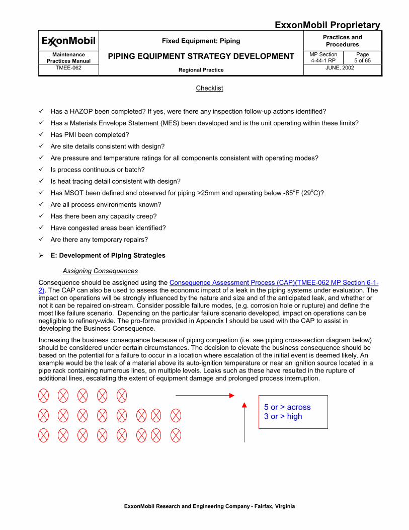
Checklist
� Has a HAZOP been completed? If yes, were there any inspection follow-up actions identified?
� Has a Materials Envelope Statement (MES) been developed and is the unit operating within these limits?
� Has PMI been completed?
� Are site details consistent with design?
� Are pressure and temperature ratings for all components consistent with operating modes?
� Is process continuous or batch?
� Is heat tracing detail consistent with design?
� Has MSOT been defined and observed for piping >25mm and operating below -85oF (29oC)?
� Are all process environments known?
� Has there been any capacity creep?
� Have congested areas been identified?
� Are there any temporary repairs?
� E: Development of Piping Strategies
Assigning Consequences
Consequence should be assigned using the Consequence Assessment Process (CAP)(TMEE-062 MP Section 6-1-2). The CAP can also be used to assess the economic impact of a leak in the piping systems under evaluation. Theimpact on operations will be strongly influenced by the nature and size and of the anticipated leak, and whether ornot it can be repaired on-stream. Consider possible failure modes, (e.g. corrosion hole or rupture) and define themost like failure scenario. Depending on the particular failure scenario developed, impact on operations can benegligible to refinery-wide. The pro-forma provided in Appendix I should be used with the CAP to assist indeveloping the Business Consequence.
Increasing the business consequence because of piping congestion (i.e. see piping cross-section diagram below)should be considered under certain circumstances. The decision to elevate the business consequence should bebased on the potential for a failure to occur in a location where escalation of the initial event is deemed likely. Anexample would be the leak of a material above its auto-ignition temperature or near an ignition source located in apipe rack containing numerous lines, on multiple levels. Leaks such as these have resulted in the rupture ofadditional lines, escalating the extent of equipment damage and prolonged process interruption.
5 or > across3 or > high
ExxonMobil ProprietaryFixed Equipment: Piping Practices and
ProceduresMaintenance
Practices ManualPIPING EQUIPMENT STRATEGY DEVELOPMENT MP Section
4-44-1 RPPage
6 of 65TMEE-062 Regional Practice JUNE, 2002
ExxonMobil Research and Engineering Company - Fairfax, Virginia
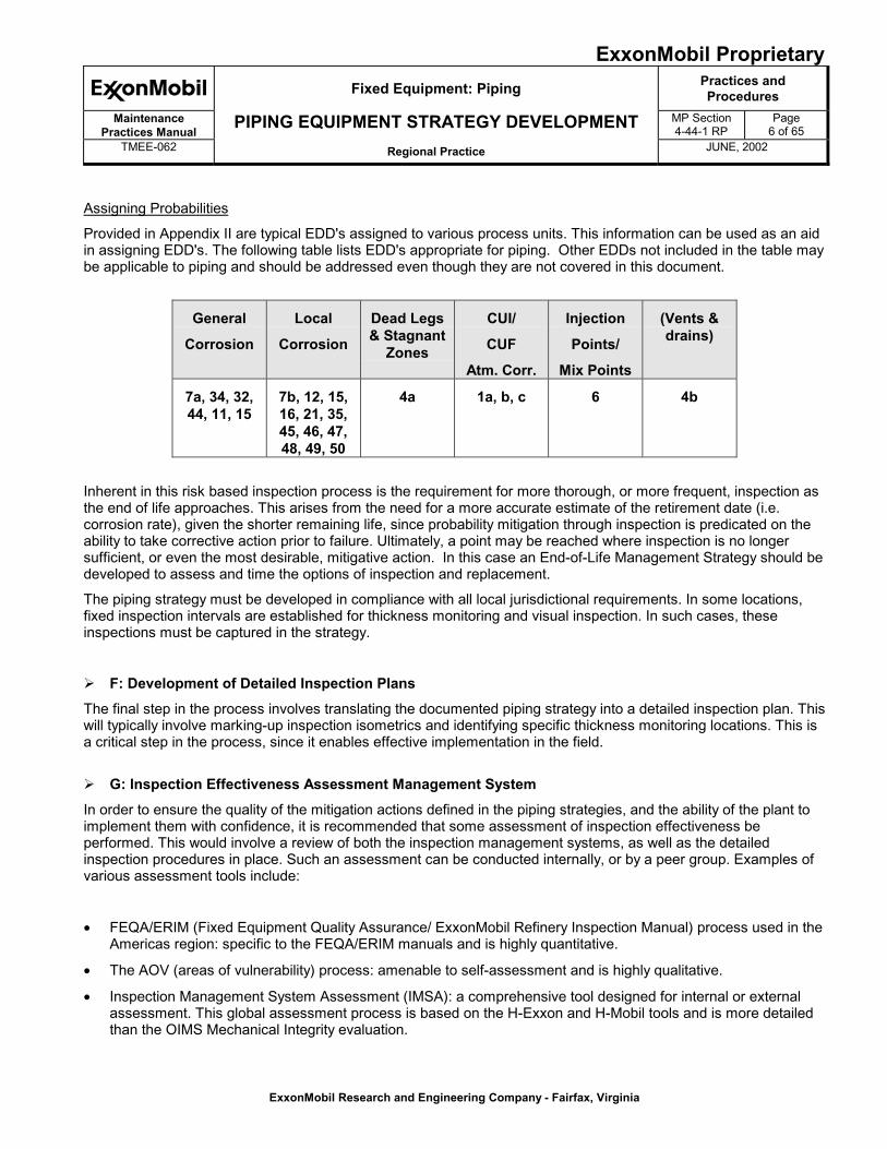
Assigning Probabilities
Provided in Appendix II are typical EDD's assigned to various process units. This information can be used as an aidin assigning EDD's. The following table lists EDD's appropriate for piping. Other EDDs not included in the table maybe applicable to piping and should be addressed even though they are not covered in this document.
General
Corrosion
Local
Corrosion
Dead Legs& Stagnant
Zones
CUI/
CUF
Atm. Corr.
Injection
Points/
Mix Points
(Vents &drains)
7a, 34, 32,44, 11, 15
7b, 12, 15,16, 21, 35,45, 46, 47,48, 49, 50
4a 1a, b, c 6 4b
Inherent in this risk based inspection process is the requirement for more thorough, or more frequent, inspection asthe end of life approaches. This arises from the need for a more accurate estimate of the retirement date (i.e.corrosion rate), given the shorter remaining life, since probability mitigation through inspection is predicated on theability to take corrective action prior to failure. Ultimately, a point may be reached where inspection is no longersufficient, or even the most desirable, mitigative action. In this case an End-of-Life Management Strategy should bedeveloped to assess and time the options of inspection and replacement.
The piping strategy must be developed in compliance with all local jurisdictional requirements. In some locations,fixed inspection intervals are established for thickness monitoring and visual inspection. In such cases, theseinspections must be captured in the strategy.
� F: Development of Detailed Inspection PlansThe final step in the process involves translating the documented piping strategy into a detailed inspection plan. Thiswill typically involve marking-up inspection isometrics and identifying specific thickness monitoring locations. This isa critical step in the process, since it enables effective implementation in the field.
� G: Inspection Effectiveness Assessment Management SystemIn order to ensure the quality of the mitigation actions defined in the piping strategies, and the ability of the plant toimplement them with confidence, it is recommended that some assessment of inspection effectiveness beperformed. This would involve a review of both the inspection management systems, as well as the detailedinspection procedures in place. Such an assessment can be conducted internally, or by a peer group. Examples ofvarious assessment tools include:
� FEQA/ERIM (Fixed Equipment Quality Assurance/ ExxonMobil Refinery Inspection Manual) process used in theAmericas region: specific to the FEQA/ERIM manuals and is highly quantitative.
� The AOV (areas of vulnerability) process: amenable to self-assessment and is highly qualitative.
� Inspection Management System Assessment (IMSA): a comprehensive tool designed for internal or externalassessment. This global assessment process is based on the H-Exxon and H-Mobil tools and is more detailedthan the OIMS Mechanical Integrity evaluation.
ExxonMobil ProprietaryFixed Equipment: Piping Practices and
ProceduresMaintenance
Practices ManualPIPING EQUIPMENT STRATEGY DEVELOPMENT MP Section
4-44-1 RPPage
7 of 65TMEE-062 Regional Practice JUNE, 2002
ExxonMobil Research and Engineering Company - Fairfax, Virginia
� Available Tools to Facilitate Piping Strategy DevelopmentThe various tools available for developing piping strategies are described below.
Tools for Piping Strategy Development
Step Tools &
Resources
Comments
Risk Management � Site specificPresentation
Reach alignment with management on riskacceptance and mitigation.
Prioritization/
AssessingBusiness Impact
� Pro-Forma(Appendix I)
� API 570classification
� Existing criticalpiping list
Appendix I provides a pro-forma that can beused to develop a criticality listing of pipingbased on SHE and business impacts due toleaks and the likely repair scenario.
"Hazop"Questionnaire
� InspectionHazop checklist
This is designed to capture any potentialhigh-risk areas during the strategydevelopment process and provide a basisfor discussion with Operations.
Data Collection &Verification
� Checklist
� EMSR(UMR)
� Inspectiondatabase
� P&ID’s
The checklist is designed to ensure that allthe data needed to develop a high qualitystrategy will be available and up to date.
AssigningMaterials EDD'sand Probabilities
� EDD's
� “ar/t” Calculator
� Appendix II
EDD assignment may be taken from anexisting EMSR, or assigned with the help ofAppendix II. Probabilities will be assigneddirectly from the EDD. The “ar/t” calculatormay also be helpful in developing mitigatedand unmitigated probabilities. It is located atthe EMRE R&M website.http://emre.na.xom.com/eedrm/docs_s00c/ARTCalc/ARTCalc.ASP
AssigningConsequences
� ConsequenceAssessmentProcedure(CAP)
Consequence must be assigned by the PMTusing the RMMS CAP process
InspectionAssessment
� IMSA
� FEQA/ERIM
� AOV
IMSA and the FEQA/ERIM processesprovides an OIMS-type evaluation ofinspection systems and their effectiveness.The AOV process is a high level approachamenable to entire units.
ExxonMobil ProprietaryFixed Equipment: Piping Practices and
ProceduresMaintenance
Practices ManualPIPING EQUIPMENT STRATEGY DEVELOPMENT MP Section
4-44-1 RPPage
8 of 65TMEE-062 Regional Practice JUNE, 2002
ExxonMobil Research and Engineering Company - Fairfax, Virginia
Section II: Piping Strategy Development
DefinitionsWhere possible, the terms used are consistent with the definitions in ASME B-31.3 section 300.2 and the RMMSdocumentation. The following definitions are added to help clarify the procedure.
� "Line" and "Piping" are taken to be synonymous. In this procedure a "line" is assumed to extend from one pieceof equipment to another
� "Piping System", and "Group of lines" are taken to be synonymous
� "TML" refers to a thickness measurement location, e.g. an elbow, tee, reducer, or straight run
� "Test point" is the inspection point at the TML (e.g. one of four points around the circumference of the pipe
1.0 Approach to Piping Strategy Development
Piping Strategies provide consistent, long term programs for piping systems (both onsite and offsite) whichrecognizes risk based decisions for establishing preventative, predictive, and run with no inspection options. Thestrategy can also provide directives for condition and operations monitoring and for calendar based maintenanceprograms.
A piping strategy, as used in this document, covers an onsite piping system (or offsite piping system if required)identified on a Engineering Flow Diagram (EFD), by line number, or through another, similar identification system.The piping system may contain an individual line or a group of lines. The items/components included in the pipingstrategy are pipe and fittings up to and including the first process block valve or instrument block valve. In general,fixed equipment nozzles and flanges should be included in the fixed equipment strategy, and not the PipingStrategy. Sections 2 to 6 give guidance on developing an inspection programs for local and general corrosion,Process Dead Leg Corrosion EDD 4a, Injection/Mix Point Corrosion EDD 6, Corrosion Under Insulation EDD 1(a),and Vents and Drains EDD 4(b), respectively.
It is expected that refinery-wide 'generic' strategies (e.g. external visual inspection programs) will be developed tocover such issues as:
� Soil Corrosion EDD 14
� Atmospheric Corrosion EDD1(b)
� Corrosion at Pipe Supports EDD 20
The outcome of these preliminary "generic" strategies should be integrated into the piping strategies for 'groups' oflines wherever possible. This will enable the most efficient integration of inspection programs.
ExxonMobil ProprietaryFixed Equipment: Piping Practices and
ProceduresMaintenance
Practices ManualPIPING EQUIPMENT STRATEGY DEVELOPMENT MP Section
4-44-1 RPPage
9 of 65TMEE-062 Regional Practice JUNE, 2002
ExxonMobil Research and Engineering Company - Fairfax, Virginia
ProcedureThe recommended procedure for developing piping strategies is described below and shown in Figure 1. It isintended that as many lines as possible be grouped together for a single strategy. This will reduce the time tocomplete the strategies, and potentially reduce the extent of inspection. In some cases a single line within a groupmay be used to represent the whole group.
1.1 Data Collection
The development of a piping strategy begins with data collection and line definition. Typically, a line goingfrom one piece of equipment to another is given an individual identification tag. The information ultimatelyneeded to develop a piping strategy such as fluid type, wall thickness, corrosion rate and degradationmechanism is available from EMSR or other activities. If sufficient data to evaluate the risk of failure doesnot already exist, then the data will need to be gathered.
1.2 Identify Lines That are “Run With No Inspection”
A 'risk-based screening process' should now be used to determine which piping, is of such 'low risk', thatminimal or no inspection is anticipated. This process must be conducted with, or approved by, therefinery PMT or management team. Lines falling into this category are regarded as 'run with noinspection'. Lines such as air, nitrogen, cooling water and firewater may fall into this category.Additionally, some offsite lines may also fall into this category. These lines should be listed, and a singlestrategy developed.
1.3 Initial Grouping
At this point, the 'grouping' can begin. It is recommended that the initial GROUP be based on theprocess-side fluid. This is likely to be a piping system within a unit. Similar but not identical fluids can beincluded as one group, but from a practical viewpoint, they should be separated. This initial GROUP formsthe basis of one Piping Strategy.
1.4 Identify EDD’s
The detailed line and operating parameters must now be available (from the EMSR). This enables theEDD's to be defined, and the unmitigated probabilities to be determined.
1.5 Breaking Down Groups into ComponentsThe next step is to segregate out lines, or segments of lines, within a GROUP to form sub-groups orCOMPONENTS. These COMPONENTS will have a similar risk, degradation mechanisms (EDDs),corrosion rate and remaining life. The intent is that any one line in the sub-group of lines could berepresentative of the entire sub-group. An analogy can be made between a piping system and a vessel.The drum is the "equipment" and the whole drum is affected by one or more degradation mechanisms(EDDs). The drum may have components such as a boot or a demister which require listing as"components". The piping system (GROUP) is the "equipment", which will have a predominant EDD.Within each system there will be different parts or "COMPONENTS". Items such as those listed belowcould be listed in the Piping Strategy as "COMPONENTS":
- Individual pipe sections or groups of lines, with unique features such as corrosion rate, remaining life,or material (e.g. define subgroups with similar probability as separate components)
- Mix points and injection points
- Process dead-legs
ExxonMobil ProprietaryFixed Equipment: Piping Practices and
ProceduresMaintenance
Practices ManualPIPING EQUIPMENT STRATEGY DEVELOPMENT MP Section
4-44-1 RPPage
10 of 65TMEE-062 Regional Practice JUNE, 2002
ExxonMobil Research and Engineering Company - Fairfax, Virginia
While each component will have its own inspection requirements, it is still part of a single EquipmentStrategy. An example of the grouping process is provided in Appendix III.
1.6 Segregating out Unique Lines
If a line cannot be grouped with others because of a unique degradation mechanism or because the riskis too, a separate strategy should be developed. Lines that are bad actors (i.e. have high corrosion rates,or high risk) should have individual strategies developed.
1.7 Developing Strategies
Individual piping strategies can now be developed for each group of lines or where necessary for single,high risk, individual lines.
1.8 Re-assess Piping Strategy
If, after developing Piping Strategies, an unexpected leak occurs then the probability of a leak in thesystem should be re-assessed. The level of any additional (follow-up) inspection should be based on thenew risk.
Developing the Strategies in STRIPES or PESTRAThe following steps can be used to develop the piping strategies in STRIPES or PESTRA. The individual strategy isused for both a GROUP of lines, and for a single line, if justified. The following steps assume that the lines havebeen grouped using the procedure outlined in this Practice. A unique tag number is assigned to a GROUP or asingle line for which a strategy is to be developed. The STRIPES or PESTRA strategy form is filled out in the samemanner as for any fixed equipment item.
The period considered should be set relative to the expected life. For many piping systems, 10 years is areasonable starting point. For most unspared process piping, two unit run lengths should be the maximum periodconsidered.
Under "components" it is usually not necessary to separately list fittings (elbows, flanges, and valves) or otherfittings as they are either covered by separate strategies or are effected by the same degradation mechanisms asthe pipe.
The detailed inspection program, as documented on the individual inspection isometrics, will identify the bestlocations for inspection. For example, a strategy covering a gasoil system in a pipestill unit may have "pipe" as theonly component. The elbows, fittings and valves would be covered by the evaluation of the corrosion mechanismand the resulting inspection program for the "pipe". Any piping component not covered by a separate equipmentstrategy and having a degradation mechanism different from the pipe should be listed as a separate component. Ifthe strategy covers a group of lines, it is recommended that the line list be included in the "comments" section of thestrategy.
ExxonMobil ProprietaryFixed Equipment: Piping Practices and
ProceduresMaintenance
Practices ManualPIPING EQUIPMENT STRATEGY DEVELOPMENT MP Section
4-44-1 RPPage
11 of 65TMEE-062 Regional Practice JUNE, 2002
ExxonMobil Research and Engineering Company - Fairfax, Virginia
2.0 Inspection for Uniform and Localized Corrosion
This section provides a step-by-step procedure to evaluate the probability of failure for EDD's classified as uniformor localized corrosion, where the failure mode is expected to be a leak. Steps 1 - 6 provide the basic probability offailure as a function of inspection method and projected pipe wall thickness. Steps 7 - 9 provide tools to modify thisprobability based on the accuracy of the inspection data, and the period of time over which the thickness is beingprojected. Modifying the probability is at the discretion of the subject matter expert. Step 10 helps indicate how thefinal probability is used to develop the strategy.
It is recommended during construction to take reference wall thickness measurements for lines with EDDs foruniform and localized corrosion especially for Consequence I and II lines. It is preferred that the reference readingsbe taken on all lines previously mentioned since scaffold and insulation removal costs can be avoided.
It is expected that this approach will apply to most services. However, it should be emphasized that there may besome unique circumstances in which the corrosion is so highly localized (e.g. pitting corrosion) that the corrosionrate can not be predicted with confidence. In such cases, use of this procedure may not be appropriate. Someexamples may include:
� Acid services where velocities exceed recommended limits for the material
� Lines containing naphthenic acid exceeding recommended TAN/TRS and velocity limits
� Lines with two-phase flow where turbulence effects can produce extremely high local corrosion rates
It should be noted that non-uniform corrosion does not mean pitting. Pitting should be considered unpredictableunless special evaluation/analysis proves differently.
In such cases, it will be necessary to estimate the unmitigated and mitigated probabilities on a case-specific basis.
Step 1: Determine if the EDD (corrosion mechanism) is uniform or localized.
Step 2: From inspection records determine the number of inspections that have been performed.
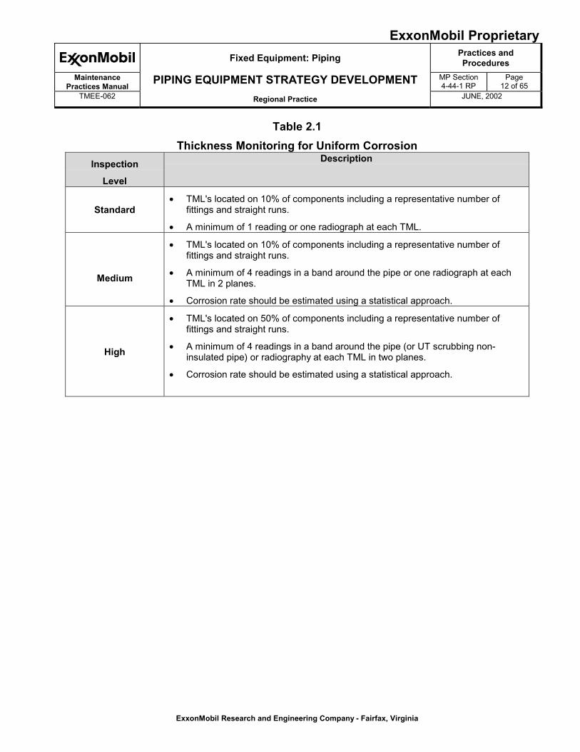
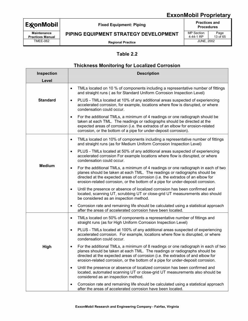
Step 3: Review the inspection procedures that have been employed. Using Tables 2.1 and 2.2 identify theinspection level that best describes the inspection methods used.
ExxonMobil ProprietaryFixed Equipment: Piping Practices and
ProceduresMaintenance
Practices ManualPIPING EQUIPMENT STRATEGY DEVELOPMENT MP Section
4-44-1 RPPage
12 of 65TMEE-062 Regional Practice JUNE, 2002
ExxonMobil Research and Engineering Company - Fairfax, Virginia
Table 2.1Thickness Monitoring for Uniform Corrosion
Inspection
Level
Description
Standard� TML's located on 10% of components including a representative number of
fittings and straight runs.
� A minimum of 1 reading or one radiograph at each TML.
Medium
� TML's located on 10% of components including a representative number offittings and straight runs.
� A minimum of 4 readings in a band around the pipe or one radiograph at eachTML in 2 planes.
� Corrosion rate should be estimated using a statistical approach.
High
� TML's located on 50% of components including a representative number offittings and straight runs.
� A minimum of 4 readings in a band around the pipe (or UT scrubbing non-insulated pipe) or radiography at each TML in two planes.
� Corrosion rate should be estimated using a statistical approach.
ExxonMobil ProprietaryFixed Equipment: Piping Practices and
ProceduresMaintenance
Practices ManualPIPING EQUIPMENT STRATEGY DEVELOPMENT MP Section
4-44-1 RPPage
13 of 65TMEE-062 Regional Practice JUNE, 2002
ExxonMobil Research and Engineering Company - Fairfax, Virginia
Table 2.2
Thickness Monitoring for Localized CorrosionInspection
Level
Description
Standard
� TMLs located on 10 % of components including a representative number of fittingsand straight runs ( as for Standard Uniform Corrosion Inspection Level)
� PLUS - TMLs located at 10% of any additional areas suspected of experiencingaccelerated corrosion, for example, locations where flow is disrupted, or wherecondensation could occur.
� For the additional TMLs, a minimum of 4 readings or one radiograph should betaken at each TML. The readings or radiographs should be directed at theexpected areas of corrosion (i.e. the extrados of an elbow for erosion-relatedcorrosion, or the bottom of a pipe for under-deposit corrosion).
Medium
� TMLs located on 10% of components including a representative number of fittingsand straight runs (as for Medium Uniform Corrosion Inspection Level)
� PLUS - TMLs located at 50% of any additional areas suspected of experiencingaccelerated corrosion For example locations where flow is disrupted, or wherecondensation could occur.
� For the additional TMLs, a minimum of 4 readings or one radiograph in each of twoplanes should be taken at each TML. The readings or radiographs should bedirected at the expected areas of corrosion (i.e. the extrados of an elbow forerosion-related corrosion, or the bottom of a pipe for under-deposit corrosion.
� Until the presence or absence of localized corrosion has been confirmed andlocated, scanning UT, scrubbing UT or close-grid UT measurements also shouldbe considered as an inspection method.
� Corrosion rate and remaining life should be calculated using a statistical approachafter the areas of accelerated corrosion have been located.
High
� TMLs located on 50% of components a representative number of fittings andstraight runs (as for High Uniform Corrosion Inspection Level)
� PLUS - TMLs located at 100% of any additional areas suspected of experiencingaccelerated corrosion. For example, locations where flow is disrupted, or wherecondensation could occur.
� For the additional TMLs, a minimum of 8 readings or one radiograph in each of twoplanes should be taken at each TML. The readings or radiographs should bedirected at the expected areas of corrosion (i.e. the extrados of and elbow forerosion-related corrosion, or the bottom of a pipe for under-deposit corrosion.
� Until the presence or absence of localized corrosion has been confirmed andlocated, automated scanning UT or close-grid UT measurements also should beconsidered as an inspection method.
� Corrosion rate and remaining life should be calculated using a statistical approachafter the areas of accelerated corrosion have been located.
ExxonMobil ProprietaryFixed Equipment: Piping Practices and
ProceduresMaintenance
Practices ManualPIPING EQUIPMENT STRATEGY DEVELOPMENT MP Section
4-44-1 RPPage
14 of 65TMEE-062 Regional Practice JUNE, 2002
ExxonMobil Research and Engineering Company - Fairfax, Virginia
Step 4: Based on the number of inspections and the level, use Table 2.3 to establish what curve isapplicable.
Table 2.3Credit for Multiple Inspections
Number/Level of Inspections1 CURVE TO USEFIGURE 2.1
No Inspection Curve 0
1 Standard Curve 1
2 or more Standard Curve 2
1 Medium Curve 2
2 Medium
or
1Medium + at least 2 Standard
Curve 3
1 High Curve 3
2 High Curve 41 Note: It is assumed that at least one baseline inspection has been performed. Nominal values are notconsidered an inspection.If no previous inspections have been performed, the date of the initial inspection should be based on the probabilitydetermined by Curve 0 in Figure 2.1 and the consequence.
Step 5: Using the thickness data for the system, calculate the value of “ar/t”, (the percentage of theremaining corrosion allowance consumed), for a test point, TML, or the entire system, where:
a – Time period under consideration, i.e., the equipment strategy time frame taken from the date oflast inspection (years).
r – Corrosion rate, determined by thickness readings, estimated from similar service, or based ondesign (e.g. RCMM) (mpy or mm/yr).
t – Remaining corrosion allowance. This is defined as the difference between the measuredthickness at the last inspection and the retirement thickness, where the
retirement thickness is determined from the Piping Maintenance Guide Section 5.4.2. (in., mm.)
t = tmeasured - tretirement
It should be emphasized that the curves relating ar/t to the probability of failure are based on the use of "t" asdefined above. The application of fitness for service type approaches (e.g. Savepipe, Peas, etc.) to redefine theacceptable wall thickness is not within the scope of this approach. Refer to SME for Guidance on risk assessmentfor these situations.
ExxonMobil ProprietaryFixed Equipment: Piping Practices and
ProceduresMaintenance
Practices ManualPIPING EQUIPMENT STRATEGY DEVELOPMENT MP Section
4-44-1 RPPage
15 of 65TMEE-062 Regional Practice JUNE, 2002
ExxonMobil Research and Engineering Company - Fairfax, Virginia
To establish a representative value of ar/t for a line or a system, it is recommended that the average corrosion ratefor the system be applied to the minimum thickness measured at the last inspection. In general, this will produce areasonable estimate of ar/t. Use of statistical methods for the estimation of corrosion rate and minimum thicknesswill provide more consistent results, and can automate this process.
Use of the nominal thickness as a start point can be useful to calculate the corrosion rate, especially in the case ofold piping. If the interval is high (e.g. >20 years) the effect of the error on the initial thickness becomes increasinglyless significant.
Example of “ar/t” Calculation
Given a 4” line inspected 5 years ago, and an equipment strategy timeframe of 10 years. The inspectiondata indicate the line thickness was 0.2” at the last inspection, and has a corrosion rate of 4 mpy. ThePiping Maintenance Guide Table 5.1 retirement thickness is 0.134”. Determine “ar/t” at the end of the timeperiod:
In this example, “a” is the piping strategy period plus the time since last inspection, or 15 years. Thecorrosion rate, “r”, is 4 mpy. The value of “t” is simply 0.2” – 0.134” or 0.066”.
Therefore, the quantity “ar/t” for the time period is calculated as:
ar/t = 15 years x 0.004”/years = 0.91
0.066”
Which means that10 years from now, it is anticipated that 91% of the remaining corrosion allowance will beconsumed.
If an inspection is conducted during this time period, the thickness and corrosion rate must be re-established at the time of the future inspection. The corresponding value of “a” must also be reset based onthe time remaining until the end of the piping strategy period, producing a new value for “ar/t”.
A convenient tool for evaluating ar/t and planning future inspections is provided at the EMRE R&M website:
http://ereweb.ere.exxon.com/eedrm/
This tool will automate the calculation of ar/t, as well as establish the probability, timing and level requiredfor future inspections.
ExxonMobil ProprietaryFixed Equipment: Piping Practices and
ProceduresMaintenance
Practices ManualPIPING EQUIPMENT STRATEGY DEVELOPMENT MP Section
4-44-1 RPPage
16 of 65TMEE-062 Regional Practice JUNE, 2002
ExxonMobil Research and Engineering Company - Fairfax, Virginia
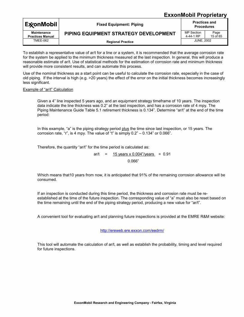
Step 6: Using the value of ar/t and the appropriate curve, establish the probability of failure using Figure2.1.
Figure 2.1
0.0 0.1 0.2 0.3 0.4 0.5 0.6 0.7 0.8 0.9 1.0
ar/t
A
B
C
E
D
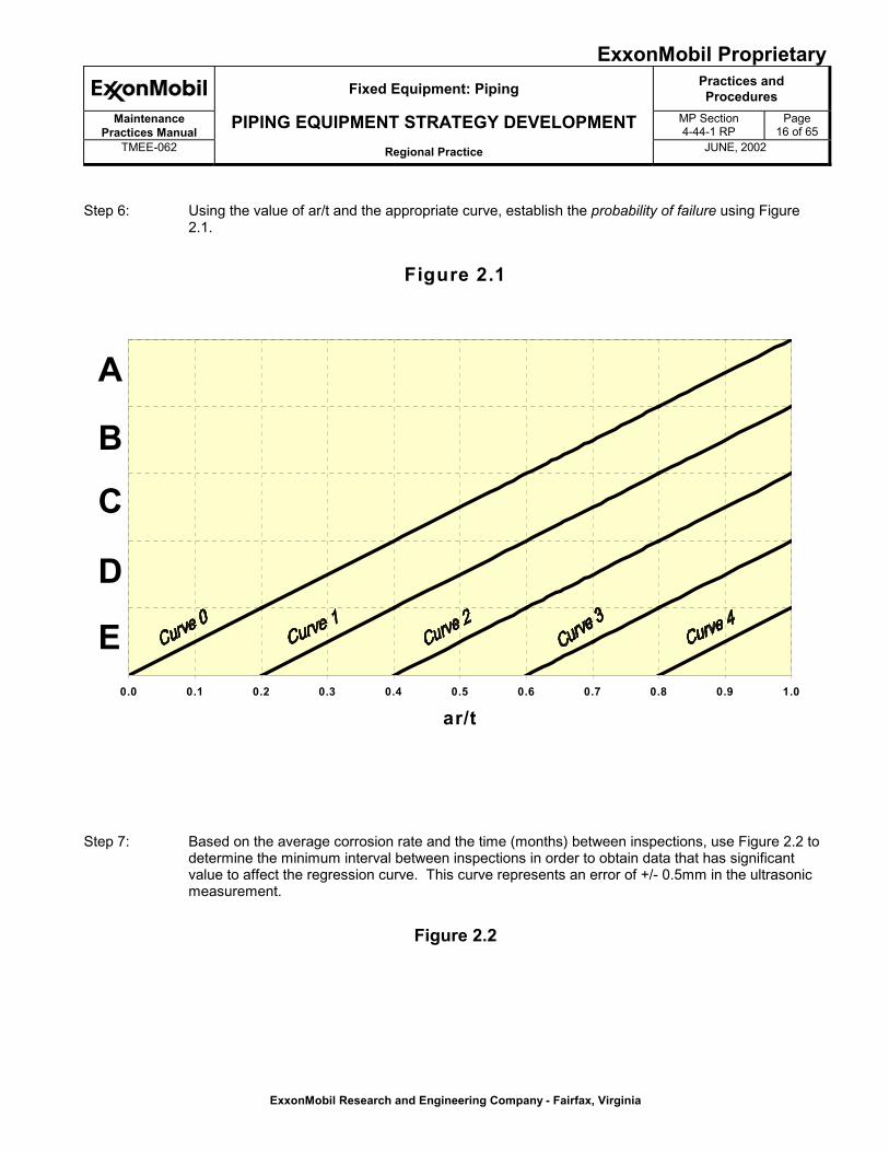
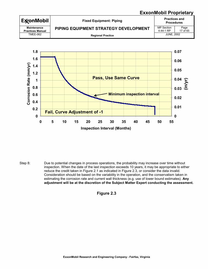
Step 7: Based on the average corrosion rate and the time (months) between inspections, use Figure 2.2 todetermine the minimum interval between inspections in order to obtain data that has significantvalue to affect the regression curve. This curve represents an error of +/- 0.5mm in the ultrasonicmeasurement.
Figure 2.2
ExxonMobil ProprietaryFixed Equipment: Piping Practices and
ProceduresMaintenance
Practices ManualPIPING EQUIPMENT STRATEGY DEVELOPMENT MP Section
4-44-1 RPPage
17 of 65TMEE-062 Regional Practice JUNE, 2002
ExxonMobil Research and Engineering Company - Fairfax, Virginia
0
0.2
0.4
0.6
0.8
1
1.2
1.4
1.6
1.8
0 5 10 15 20 25 30 35 40 45 50 55Inspection Interval (Months)
Cor
rosi
on R
ate
(mm
/yr)
0
0.01
0.02
0.03
0.04
0.05
0.06
0.07
(in/y
r)Pass, Use Same Curve
Fail, Curve Adjustment of -1
Minimum inspection interval
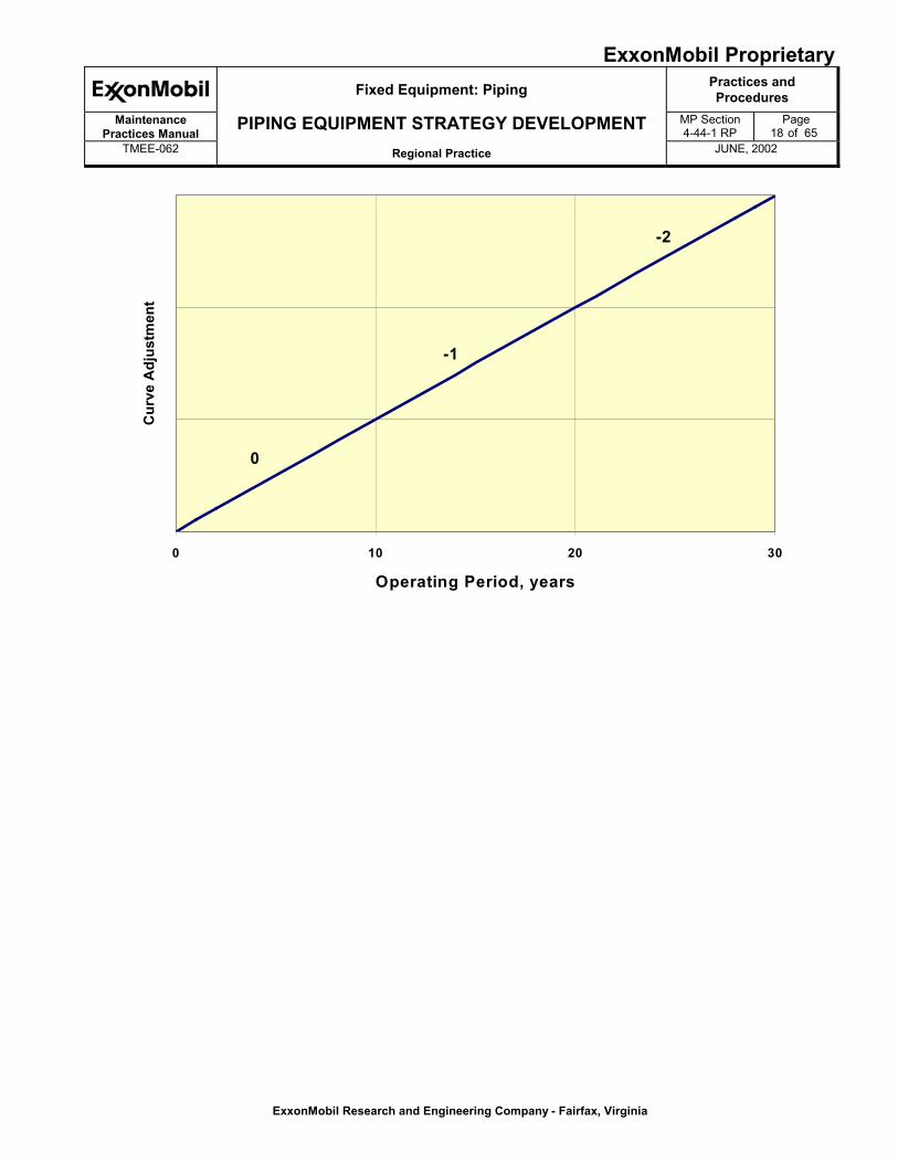
Step 8: Due to potential changes in process operations, the probability may increase over time withoutinspection. When the date of the last inspection exceeds 10 years, it may be appropriate to eitherreduce the credit taken in Figure 2.1 as indicated in Figure 2.3, or consider the data invalid.Consideration should be based on the variability in the operation, and the conservatism taken inestimating the corrosion rate and current wall thickness (e.g. use of lower bound estimates). Anyadjustment will be at the discretion of the Subject Matter Expert conducting the assessment.
Figure 2.3
ExxonMobil ProprietaryFixed Equipment: Piping Practices and
ProceduresMaintenance
Practices ManualPIPING EQUIPMENT STRATEGY DEVELOPMENT MP Section
4-44-1 RPPage
18 of 65TMEE-062 Regional Practice JUNE, 2002
ExxonMobil Research and Engineering Company - Fairfax, Virginia
0 10 20 30
Operating Period, years
Cur
ve A
djus
tmen
t
-1
-2
0
ExxonMobil ProprietaryFixed Equipment: Piping Practices and
ProceduresMaintenance
Practices ManualPIPING EQUIPMENT STRATEGY DEVELOPMENT MP Section
4-44-1 RPPage
19 of 65TMEE-062 Regional Practice JUNE, 2002
ExxonMobil Research and Engineering Company - Fairfax, Virginia
Step 9: Using the results from steps 7 and 8, update the probability of failure using Figure 2.1. Note thatCurve 0 is the lowest curve that should be used.
Step 10: Assign a risk corresponding to the probability and consequence. Based on this risk, determine ifand when an inspection is required during the time period to help mitigate to an acceptable level. Insome cases, a comparison should be made between performing multiple “standard” inspections, ora higher level inspection, in order to select the optimum strategy.
The anticipated mitigated risk is defined at the end of the time frame or the next replacementopportunity using the "ar/t" and proposed inspection level according to figure 2.1. If the risk lies inan acceptable position on the risk matrix at the end of the time period, no further action is required.
If inspection is required during the period, the next inspection interval can be determined based ona target probability necessary to maintain an acceptable overall risk. This is done by calculating thetime required to reach an unacceptable probability of failure. This analysis can also be done usingthe “ar/t” calculator referred to previously.
3.0 Inspection for Corrosion-Under-Insulation CUI - EDD 1a
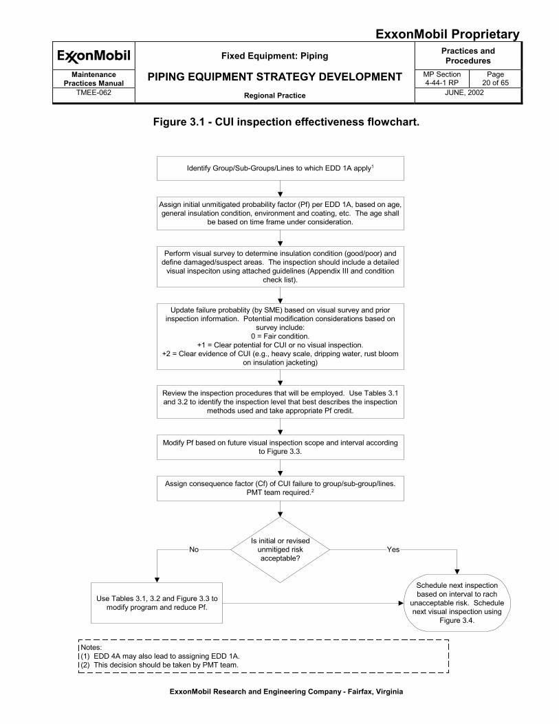
This inspection practice covers EDD #1a only. Lines in cyclic or sweating service require site specific consideration,beyond the scope of this document. Atmospheric corrosion and Corrosion Under Fireproofing (CUF) are notincluded within the scope of this document. A step-by-step process has been included and a corresponding flowchart, shown in Figure 3.1, summarizes the key steps in using this practice. While inspection personnel mayaddress many of the tasks in this process, the PMT team should jointly identify at least two parts (consequenceassessment and determining appropriate mitigation levels).
Step 1: Set initial probability and perform visual inspection. EDD 1a provides an initial failure probability (Pf)based on time in service and operating information. An initial visual inspection should be performedand will improve the failure probability estimate and may increase failure probability by up to twolevels. (Many sites perform these inspections during routine thickness monitoring.) Severalresources (e.g., API 570, ERIM 12.3.4 (as Appendix VII, etc.) are available to provide guidance oninsulation assessments. Examples are included in Appendix IV. A probability reduction based onthe visual inspection is not considered since the EDD assumes reasonable condition for insulationand a poorer condition may be found. If the initial visual inspection identifies that the insulationsystem is in good condition, the basic probability may be retained. If the insulation system is not ingood condition, the probability should be raised by one or two levels (up to an "A"). Recentinspection information may also be used to modify the EDD probability. Probability modificationsassociated with external visual inspection and recent inspections (e.g., radiography, visual, etc.) areat the discretion of the Subject Matter Expert.
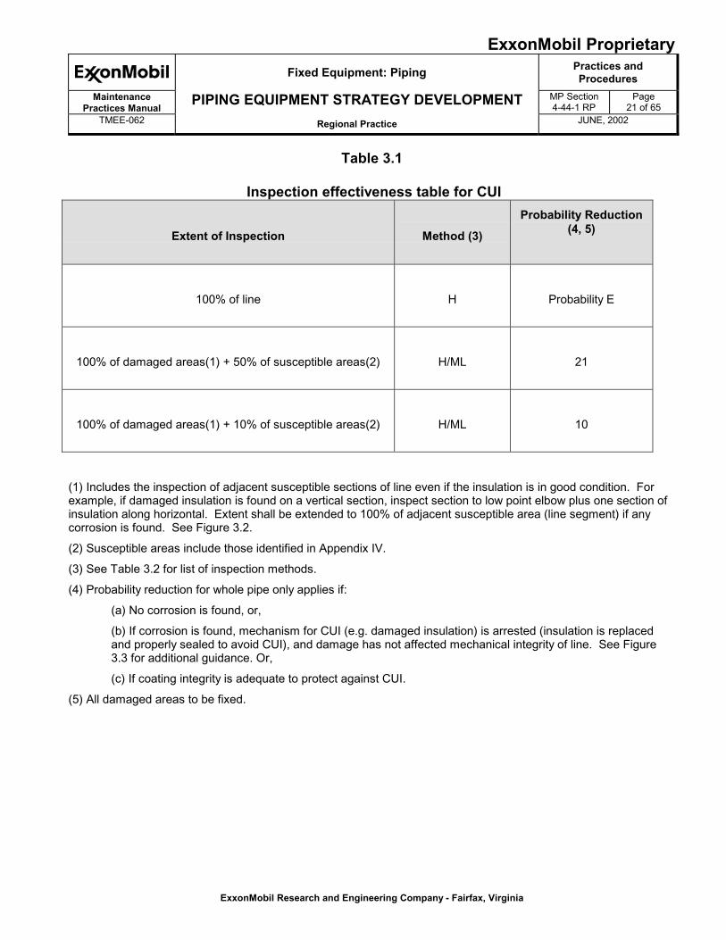
Step 2: Review the inspection procedures that will be employed. Using Tables 3.1 and 3.2 (for extent andmethod, respectively) identify the inspection level that best describes the inspection methods used.Table 3.1 lists the amount of mitigation credit for different combinations of inspection technology,and coverage. While neutron backscatter is only a moisture detection (not CUI) tool, some creditmay be applied since it can assist with identifying susceptible areas. Figure 3.2 provides guidanceon inspection extent for the technologies. The ExxonMobil NDT Manual contains information on theinspection technologies mentioned in this document.
ExxonMobil ProprietaryFixed Equipment: Piping Practices and
ProceduresMaintenance
Practices ManualPIPING EQUIPMENT STRATEGY DEVELOPMENT MP Section
4-44-1 RPPage
20 of 65TMEE-062 Regional Practice JUNE, 2002
ExxonMobil Research and Engineering Company - Fairfax, Virginia
Figure 3.1 - CUI inspection effectiveness flowchart.
Identify Group/Sub-Groups/Lines to which EDD 1A apply1
Notes:(1) EDD 4A may also lead to assigning EDD 1A.(2) This decision should be taken by PMT team.
Perform visual survey to determine insulation condition (good/poor) anddefine damaged/suspect areas. The inspection should include a detailed
visual inspeciton using attached guidelines (Appendix III and conditioncheck list).
Assign consequence factor (Cf) of CUI failure to group/sub-group/lines.PMT team required.2
Use Tables 3.1, 3.2 and Figure 3.3 tomodify program and reduce Pf.
Schedule next inspectionbased on interval to rach
unacceptable risk. Schedulenext visual inspection using
Figure 3.4.
Assign initial unmitigated probability factor (Pf) per EDD 1A, based on age,general insulation condition, environment and coating, etc. The age shall
be based on time frame under consideration.
Is initial or revisedunmitiged riskacceptable?
Yes
Update failure probablity (by SME) based on visual survey and priorinspection information. Potential modification considerations based on
survey include:0 = Fair condition.
+1 = Clear potential for CUI or no visual inspection.+2 = Clear evidence of CUI (e.g., heavy scale, dripping water, rust bloom
on insulation jacketing)
No
Review the inspection procedures that will be employed. Use Tables 3.1and 3.2 to identify the inspection level that best describes the inspection
methods used and take appropriate Pf credit.
Modify Pf based on future visual inspection scope and interval accordingto Figure 3.3.
ExxonMobil ProprietaryFixed Equipment: Piping Practices and
ProceduresMaintenance
Practices ManualPIPING EQUIPMENT STRATEGY DEVELOPMENT MP Section
4-44-1 RPPage
21 of 65TMEE-062 Regional Practice JUNE, 2002
ExxonMobil Research and Engineering Company - Fairfax, Virginia
Table 3.1
Inspection effectiveness table for CUI
Extent of Inspection Method (3)
Probability Reduction(4, 5)
100% of line H Probability E
100% of damaged areas(1) + 50% of susceptible areas(2) H/ML 21
100% of damaged areas(1) + 10% of susceptible areas(2) H/ML 10
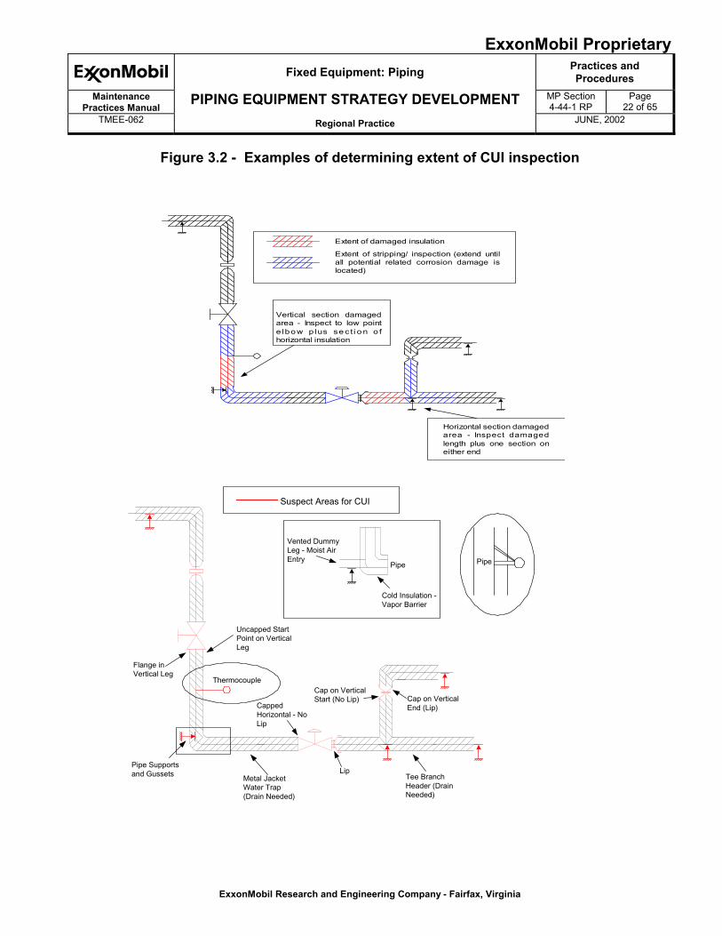
(1) Includes the inspection of adjacent susceptible sections of line even if the insulation is in good condition. Forexample, if damaged insulation is found on a vertical section, inspect section to low point elbow plus one section ofinsulation along horizontal. Extent shall be extended to 100% of adjacent susceptible area (line segment) if anycorrosion is found. See Figure 3.2.
(2) Susceptible areas include those identified in Appendix IV.
(3) See Table 3.2 for list of inspection methods.
(4) Probability reduction for whole pipe only applies if:
(a) No corrosion is found, or,
(b) If corrosion is found, mechanism for CUI (e.g. damaged insulation) is arrested (insulation is replacedand properly sealed to avoid CUI), and damage has not affected mechanical integrity of line. See Figure3.3 for additional guidance. Or,
(c) If coating integrity is adequate to protect against CUI.
(5) All damaged areas to be fixed.
ExxonMobil ProprietaryFixed Equipment: Piping Practices and
ProceduresMaintenance
Practices ManualPIPING EQUIPMENT STRATEGY DEVELOPMENT MP Section
4-44-1 RPPage
22 of 65TMEE-062 Regional Practice JUNE, 2002
ExxonMobil Research and Engineering Company - Fairfax, Virginia
Figure 3.2 - Examples of determining extent of CUI inspection
Pipe Supportsand Gussets Metal Jacket
Water Trap(Drain Needed)
Uncapped StartPoint on VerticalLeg
Flange inVertical Leg
CappedHorizontal - NoLip
LipTee BranchHeader (DrainNeeded)
Cap on VerticalStart (No Lip) Cap on Vertical
End (Lip)
Suspect Areas for CUI
Thermocouple
Pipe
Vented DummyLeg - Moist AirEntry
Cold Insulation -Vapor Barrier
Pipe
Extent of damaged insulation
Extent of stripping/ inspection (extend untilall potential related corrosion damage islocated)
Vertical section damagedarea - Inspect to low pointe lbow p lus se c t i o n o fhorizontal insulation
Horizontal section damagedarea - Inspect damagedlength plus one section oneither end
ExxonMobil ProprietaryFixed Equipment: Piping Practices and
ProceduresMaintenance
Practices ManualPIPING EQUIPMENT STRATEGY DEVELOPMENT MP Section
4-44-1 RPPage
23 of 65TMEE-062 Regional Practice JUNE, 2002
ExxonMobil Research and Engineering Company - Fairfax, Virginia
Table 3.2
CUI inspection methodsMethod
ReliabilityPrimary Methods
High
� Insulation Stripping and Visual Inspection (100%)
� Intelligent Pigging (100%)
Medium
� Conventional RT (1)
� Flash Radiography (with film) with stripping at affected areas (1)
� Real Time Radiography (tangential) with stripping at affected areas (1)
� Radiographic Scanning (through wall, e.g., ThruVu) (1)
� Guided Wave Ultrasonics on small diameter pipe (<10-inch) with follow-up for allindications (2)
Low
� Pulsed Eddy Current (e.g., INCOTEST) with follow-up for all indications(1, 2)
� Guided Wave Ultrasonics on large diameter pipe (>10-inch) with follow-up for allindications (2).
� Neutron Backscatter with ≈10% follow-up at susceptible areas with no indications(1, 3)
(1) As a minimum, RT method must be applied at 2 planes for areas with damaged insulation and 1 plane forsusceptible areas, at each location. Inspection planes/quadrants must be at most likely CUI location (e.g.,6-o'clock and 12-o'clock for horizontal pipe).
(2) Plan must consider ineffective nature of these methods to detect localized corrosion. (Credit should bereduced if localized corrosion is expected and there may be no mitigation credit for very large diameter linesinspected with guided wave UT.) Use supplemental technology (e.g., stripping, RT, or neutron backscatter)at areas of penetrations, supports or fittings. All follow-ups should be performed with a CUI (wall loss)measuring technology.
(3) Inspection will be scheduled when elevated moisture level is anticipated, for example, after significant rainperiod, after wetting through use of fire monitor (e.g., 24-hour soak), or when climate is conducive tocondensation.
ExxonMobil ProprietaryFixed Equipment: Piping Practices and
ProceduresMaintenance
Practices ManualPIPING EQUIPMENT STRATEGY DEVELOPMENT MP Section
4-44-1 RPPage
24 of 65TMEE-062 Regional Practice JUNE, 2002
ExxonMobil Research and Engineering Company - Fairfax, Virginia
Figure 3.3 - Evaluating CUI inspection results
Note (1) Acceptable wall loss must be determined using engineering judgement, taking into account such factors asdesign metal thickness, future corrosion allowance required for internal corrosion, etc. In some cases, a local thinarea assessment following fitness for service guidelines will be required.
Evaluate CUI inspectionresults for line.
Is there significantrust/scaling present (not just
light blooming)?
No
If corrosion is very slight(e.g., rust bloom), repairinsulation as needed andcapture stated probability
credit.
Yes
Is CUI at damagedinsulation area only?
Increase coverage ofsuspect areas as
appropriate.No
Yes
Yes
No
Arrest corrosion as requiredfor probability reduction in
Table 3.1.
Re-assess failure probability andconsider replacement of line.
Is wall lossacceptable (note 1)
?
ExxonMobil ProprietaryFixed Equipment: Piping Practices and
ProceduresMaintenance
Practices ManualPIPING EQUIPMENT STRATEGY DEVELOPMENT MP Section
4-44-1 RPPage
25 of 65TMEE-062 Regional Practice JUNE, 2002
ExxonMobil Research and Engineering Company - Fairfax, Virginia
Step 3: Inspection intervals are based on maintaining an acceptable level of risk, as determined by the riskmatrix. Due to the uncertainly in extrapolating inspection results over long periods of time, thepotential for unanticipated process changes (e.g., sweating), and insulation condition changes (e.g.,damaged jacketing) affecting CUI susceptibility, it may be appropriate to reduce the credit taken inTable 3.1 as indicated in Figure 3.4. The figure provides 2 different curves, which reflect whether asubsequent visual inspection is performed. The time-based guidelines are summarized below andany adjustment will be at the discretion of the subject matter expert conducting the assessment.
Case 1
� No visual inspection is performed at approximately 5 year intervals, or
Case 2
� Line is visually inspected approximately every 5 years and all new damaged areas areinspected according to Table 3.1 and repaired to arrest CUI.
� 10% of all suspect areas (e.g., attachments protruding from insulation, low spots, etc.) areinspected every 10 years.
ExxonMobil ProprietaryFixed Equipment: Piping Practices and
ProceduresMaintenance
Practices ManualPIPING EQUIPMENT STRATEGY DEVELOPMENT MP Section
4-44-1 RPPage
26 of 65TMEE-062 Regional Practice JUNE, 2002
ExxonMobil Research and Engineering Company - Fairfax, Virginia
Figure 3.4 - Time dependency for mitigation credit reduction for lines inspectedaccording to Table 3.1
0
1
2
0 5 10 15 20Years since inspection
Incr
ease
in F
ailu
re P
roba
bilit
y (lo
ss in
miti
gatio
n cr
edit
up to
unm
itiga
ted
leve
l)
Case 1 (No visual)
Case 2 (Visual inspection every 5 years)
Check suspect areas
.
Step 4: Using the results from steps 2 and 3, update the probability of failure using Figure 3.1
Step 5: Use the final probability and consequence of failure to assign the risk. Based on this risk, and theassociated acceptance criteria, determine the inspection interval and inspection level necessary tomitigate the risk to an acceptable level. If the risk lies in an acceptable position on the risk matrix,no further action is required in this time period. In some cases, such as severe CUI, inspection (andre-insulation) may not be an effective means of achieving the desired level of risk reduction. In suchcases, other mitigative steps (e.g., coating) need to be taken.
4.0 Inspection for Process Dead-leg Corrosion – EDD 4a
The unmitigated probability for dead legs, set by EDD 4a, is assigned a “C”, "D", or “E” according to the service. Forinstances where inspection data have been collected according to the methods and level indicated below (Table4.1), and a value of ar/t can be calculated with confidence, the probability can be determined from Figure 2.1.
ExxonMobil ProprietaryFixed Equipment: Piping Practices and
ProceduresMaintenance
Practices ManualPIPING EQUIPMENT STRATEGY DEVELOPMENT MP Section
4-44-1 RPPage
27 of 65TMEE-062 Regional Practice JUNE, 2002
ExxonMobil Research and Engineering Company - Fairfax, Virginia
Table 4.1
Probability
Reduction
Inspection
Level
Extent of Inspection Inspection Method InspectionInterval
Up to
3 Levels
High
Inspection along 100% of thelength of each dead-legusing a method thataddresses the expected formand location of the corrosion.E.g. for a horizontal pipe,where under-depositcorrosion is expected, 100%can be achieved by a fulllength UT scan of the bottomsection of the pipe. Anotherexample is for a partially filledhorizontal pipe with aliquid/vapor interface,inspection can be achieved bya full length UT scan of thebottom plus a series of RTshots or UT circumferencialbands at an acceptableinterval.
� Scanning UT
� Close-grid UT
� Multiple radiographs
Based onFigure 2.1
Up to
2 Levels
Medium
Inspection along 100% of the'susceptible' areas of eachdead-leg. Susceptible areasare defined as locationswhere corrosion is likely tooccur e.g. low points,condensation/vaporizationareas. Inspection methodmust address the expectedform and location of thecorrosion. E.g. for ahorizontal pipe, where under-deposit corrosion is expected100% can be achieved by afull length UT scan of thesusceptible areas of thebottom section of the pipe.
As above Based onFigure 2.1
1 Level Standard
20% of the surface area foreach dead-leg, targeted atlikely sites for acceleratedcorrosion.
As above Based onFigure 2.1
ExxonMobil ProprietaryFixed Equipment: Piping Practices and
ProceduresMaintenance
Practices ManualPIPING EQUIPMENT STRATEGY DEVELOPMENT MP Section
4-44-1 RPPage
28 of 65TMEE-062 Regional Practice JUNE, 2002
ExxonMobil Research and Engineering Company - Fairfax, Virginia
Once the unmitigated probability has been determined, the inspection plan can be developed based on the requiredprobability reduction.
Due to the highly localized nature of corrosion that is often observed in dead legs, the extent of inspection typicallyrequires that each dead leg be inspected, if required based on risk. However, where similar service can be defined,such as identical (symmetrical) piping configurations, where corrosion is expected to be of similar severity, multipledead legs may be grouped together. A representative dead leg(s) may be defined as the “witness line(s)” forinspection. When this strategy is chosen, the lines being grouped should be clearly identified in the strategy.
A valve may not divide a dead leg even if in similar service. This situation should be considered as separate deadlegs with Table 4.1 applied equally. Some caution must be exercised when grouping dead legs, particularly wherecorrosion is expected to result from the formation or collection of corrosive deposits. One example is the depositionof ammonium chloride salts in the vertical segments of cold exchanger bypasses in hydotreating units, where highlylocalized corrosion may occur in a single dead leg based on slightly different operating temperature.
5.0 Inspection for Vents and Drains (Small Connections) - EDD4b
The unmitigated probability for vents and drains, set by EDD 4b, is assigned a “C” for corrosive service, or an “E” fornon-corrosive service. In most cases, small connections are inspected on a calendar-based frequency, as corrosionrate is difficult to estimate. The mitigated probability and inspection plan/timing can be determined from Table 5.1.
Table 5.1Probability
Reduction
Inspectionlevel
Number ofInspection locations
Inspection Method Inspection Interval
Up to 3Levels
High 100% of vents &drains
� Radiography
� Ultrasonic
5 years
(If no corrosion isfound, consider not
repeating theinspection)
Up to 2Levels
Medium 50% of vents anddrains
� Radiography
� Ultrasonic
5 years
(If no corrosion isfound, consider not
repeating theinspection)
ExxonMobil ProprietaryFixed Equipment: Piping Practices and
ProceduresMaintenance
Practices ManualPIPING EQUIPMENT STRATEGY DEVELOPMENT MP Section
4-44-1 RPPage
29 of 65TMEE-062 Regional Practice JUNE, 2002
ExxonMobil Research and Engineering Company - Fairfax, Virginia
6.0 INSPECTION FOR INJECTION/MIX POINT CORROSION – EDD 6
The unmitigated probability is defined for injection or mix points using EDD 6. Based on the anticipated corrosivity ofthe service and the design, the unmitigated probability will be a “B”, “C”, or “E”. For instances where inspection dataare available, and a value of ar/t can be calculated with confidence, the probability can be determined from Figure2.1 using the definitions of inspection level provided in Table 6.1.
Table 6.1
Probability
Reduction
Inspection
level
Number of Inspectionlocations
Inspection Method InspectionInterval
Up to3 Levels
High Inspect per Appendix V & VI � Scanning UT
� Close-grid UT
� Multiple radiographs
3 years orBased on Figure
2.1
Up to 2Levels
Medium Inspect per Appendix V & VI � Point UT
� Radiography
3 years orBased on Figure
2.1
1 Level Standard
The Injection/Mix Point fittingand downstream elbow(s)can be selected as a site tobe included in the inspectionof the main piping.
� Inspected as mainpiping using UT or RT
3 years orBased on Figure
2.1
Once the unmitigated probability has been determined, the inspection plan can be developed based on the requiredprobability reduction as defined in Table 6.1. Inspection frequency should be either every 3 years, or based on anestimate of ar/t using Figure 2.1 along with the inspection level defined in Table 6.1.
ExxonMobil ProprietaryFixed Equipment: Piping Practices and
ProceduresMaintenance
Practices ManualPIPING EQUIPMENT STRATEGY DEVELOPMENT MP Section
4-44-1 RPPage
30 of 65TMEE-062 Regional Practice MAY 10, 2002
ExxonMobil Research and Engineering Company - Fairfax, Virginia
APPENDIX IExample: Piping Consequence Pro-Forma
Business Impact
Line # Primary
EDD(s)
Service Cost
($/Day)
SHE
Risk Repair
Onstream
Short Shutdown~5 Days
Major Shutdown>14 Days
Business
Risk
123A 7a Gasoil 50K II No Yes No III - $250K
654D 7a VGO 200K II No Yes No II - $1M
456B 24 HF acid 500K I No No Yes I - $7M
789C 1a, 15 Sour water 50K III Yes No No IV - <$50K
ExxonMobil ProprietaryFixed Equipment: Piping Practices and
ProceduresMaintenance
Practices ManualPIPING EQUIPMENT STRATEGY DEVELOPMENT MP Section
4-44-1 RPPage
31 of 65TMEE-062 Regional Practice JUNE, 2002
ExxonMobil Research and Engineering Company - Fairfax, Virginia
Appendix IITypical EDDs for Major Process Units
ExxonMobil ProprietaryFixed Equipment: Piping Practices and
ProceduresMaintenance
Practices ManualPIPING EQUIPMENT STRATEGY DEVELOPMENT MP Section
4-44-1 RPPage
32 of 65TMEE-062 Regional Practice JUNE, 2002
ExxonMobil Research and Engineering Company - Fairfax, Virginia
Atmospheric Distillation Unit
1
1
8
2
2
2
3
3
7
1 1
74
4
P6
3
3
2
12 13
P2
P5
S1
P11
12
17
P4S2
13
P318
1
12 13
2
12 13
2
3
3
4
or�
�
��
�
�
�
�
�
�
�
�
� �
�
�
�
�
�
�
�
� �
FiredHeater
CondensateSteam
APSTower
Steam
(If Unclad)
Booster
Desalter
CrudeAdditive
(Optional)
Neutralizer(Optional) Inhibitor
NeutralizerInhibitor
Feed
CrudeFeed
Acidic WaterCondensate
Naphtha
Acidic WaterCondensate
1st SidestreamKerosene
2nd SidestreamLight Gas Oil
3rd SidestreamHeavy Gas Oil
Reduced Crude
P
S Sample point location
Corrosion probe location
Recommended Locations for UT
Note:The circled numbers indicate appropriate Corrosion Design Curveto be used for determining corrosion rates for materials specification.
4/96-706-01D
44,4512, 8b7a, 7b7a, 7b, 18b, 28, 29, 107a, 7b, 22,107a, 7b7a, 7b, 8b44, 452, 21a, 9, 12
Applicable EDD's
ExxonMobil ProprietaryFixed Equipment: Piping Practices and
ProceduresMaintenance
Practices ManualPIPING EQUIPMENT STRATEGY DEVELOPMENT MP Section
4-44-1 RPPage
33 of 65TMEE-062 Regional Practice JUNE, 2002
ExxonMobil Research and Engineering Company - Fairfax, Virginia
Vacuum Distillation Unit
4
4
77
4,8
4
S
P
4
4
3
3
31817
1817
12
S P 2
4
12
12SP
2
21817
2
4
3
4
24
2
4
3
3
1817
1817
1817
1817
�
�
�
�
�
�
�
�
�
�
�
�
�
�
�
�
�
�
ReducedCrude Feed
Steam
Steam
Steam
Steam
SteamNeutralizer
Lube SidestreamNo. 1
Lube SidestreamNo. 2
Lube SidestreamNo. 3
Vacuum Residuum
Legend:
Sample Point Location
Corrosion Probe Location
Recommended UT Locations
Note:
The circled numbers indicateappropriate Corrosion DesignCurve to be used for determiningcorrosion rates for materialsspecifications.
4/96-694-01D
7a, 7b
7a, 7b7a, 7b, 22,1044, 45
2, 21a, 9, 12
Applicable EDD's
7a, 7b, 18b, 28, 29, 10
ExxonMobil ProprietaryFixed Equipment: Piping Practices and
ProceduresMaintenance
Practices ManualPIPING EQUIPMENT STRATEGY DEVELOPMENT MP Section
4-44-1 RPPage
34 of 65TMEE-062 Regional Practice JUNE, 2002
ExxonMobil Research and Engineering Company - Fairfax, Virginia
Hydrocracker
3
5,6 5,6
Gas OilFeed
Px
Sx
Legend
Sample Point
Corrosion Probe
�Recommended Locationfor UT
S1P1
3,5,6��
Hydro-TreatingReactor
FiredFeed Furnace
(Optional)QuenchGas
6
Hydro-CrackingReactor
Treat GasFurnace
(Optional) 6
WashWater
��
SourWater
Cold HPSeparator
Let-DownValves
5,6 5,6
26
19
12,13
RichMea
LeanMea
Recycle GasScrubber
Make-UpHydrogen
Recycle GasCompressor
26
Hot HPSeparator
Hot LPSep5,612,
13 Cold LPSep
�
Sour Water
�
FractionatorReboiler
ProductFractionator
Bottoms
Diesel
Kero
Note:The circled numbers indicateappropriate corrosion design curveto be used.
19Fuel GasScrubber
Lean MEA
Rich MEA
Fuel Gas
�
OvhdCondensers
12,13,26
OffGas
Naphtha
12,13
�
S2
P2
SourWater
�
�
Feed/EffluentExchangers Recycle Gas
(199-31-01)
15, 5
15, 12, 215, 2
18a, 18b, 17, 10, 28, 29, 9
Applicable EDD's
5, 11, 9, 17, 238a, 2, 16
7a, 7b (44, 45 cold feed section)7a, 5, 11, 17, 9, 235, 11, 9, 17, 23, 13b
ExxonMobil ProprietaryFixed Equipment: Piping Practices and
ProceduresMaintenance
Practices ManualPIPING EQUIPMENT STRATEGY DEVELOPMENT MP Section
4-44-1 RPPage
35 of 65TMEE-062 Regional Practice JUNE, 2002
ExxonMobil Research and Engineering Company - Fairfax, Virginia
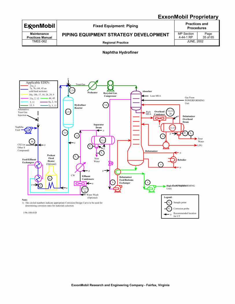
Naphtha Hydrofiner
Recycled GasCompressor
Absorber
Lean MEA
RichMEA
OverheadCondenser
Debutanizer
�
Reboiler
DebutanizerFeed/BottomsExchanger
Hydrofined Naphtha(e.g., To POWERFORMINGUnit)
9
9
12,13
Gas FromPOWERFORMINGUnit
DebutanizerOverheadDrum
P3 S2
SourWaterLPG
SeparatorDrum
AlternativeTreat GasInjection
NaphthaFeed
CS2 (orOther SCompound)
Feed/EffluentExchangers
PreheatFired
Heater(Optional)
�
2
8
�
Treat Gas
Preheater
HydrofinerReactor
12,13
9
12,13,20
50
�
�
�
Water Wash(Optional)
EffluentCondensers
�
CW
P2
S1
P1
�
125,6
2,5,6
2,5,6
�
12,13,20
�
�
�
9
�
�
SourWater
�
Note:1) The circled numbers indicate appropriate Corrosion Design Curve to be used for
determining corrosion rates for materials selection.Sx
Px
�
Legend:
Sample point
Corrosion probe
Recommended locationfor UT
1/96-108-01D
5,6
21a, 2
18a, 18b, 17, 10, 28, 29, 921a, 2, 125, 1115, 5
Applicable EDD's
7a, 7b, (44, 45 oncold feed sections)
44, 458a, 2, 167a, 5, 11
ExxonMobil ProprietaryFixed Equipment: Piping Practices and
ProceduresMaintenance
Practices ManualPIPING EQUIPMENT STRATEGY DEVELOPMENT MP Section
4-44-1 RPPage
36 of 65TMEE-062 Regional Practice JUNE, 2002
ExxonMobil Research and Engineering Company - Fairfax, Virginia
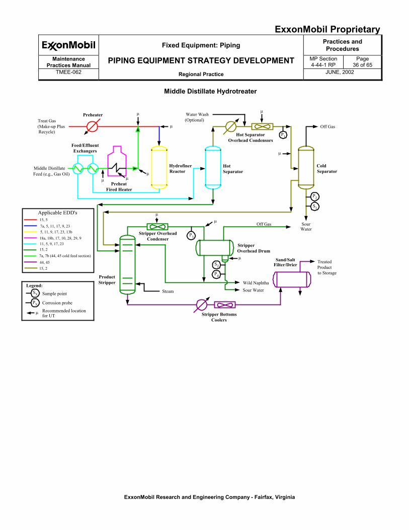
Middle Distillate Hydrotreater
Treat Gas(Make-up PlusRecycle)
Preheater
Feed/EffluentExchangers
Middle DistillateFeed (e.g., Gas Oil)
PreheatFired Heater
HydrofinerReactor
Water Wash(Optional)
Hot SeparatorOverhead Condensors
P1
Off Gas
ColdSeparator
P2
S1
SourWater
Off Gas
TreatedProductto Storage
Sand/SaltFilter/Drier
StripperOverhead Drum
Wild NaphthaSour Water
Stripper BottomsCoolers
S2
P4
Steam
Stripper OverheadCondenser
ProductStripper
P3
Legend:
Sample point
Corrosion probe
Recommended locationfor UT
HotSeparator
�
�
�
��
�
�
�
�
�
SX
PX
�
7a, 7b (44, 45 cold feed section)
44, 45
15, 2
15, 5
Applicable EDD's
11, 5, 9, 17, 23
15, 2
7a, 5, 11, 17, 9, 235, 11, 9, 17, 23, 13b18a, 18b, 17, 10, 28, 29, 9
ExxonMobil ProprietaryFixed Equipment: Piping Practices and
ProceduresMaintenance
Practices ManualPIPING EQUIPMENT STRATEGY DEVELOPMENT MP Section
4-44-1 RPPage
37 of 65TMEE-062 Regional Practice JUNE, 2002
ExxonMobil Research and Engineering Company - Fairfax, Virginia
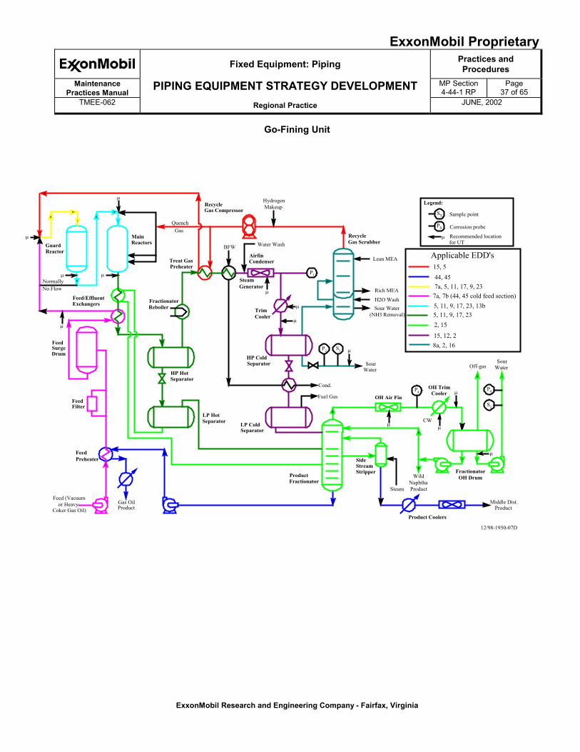
Go-Fining Unit
Gas OilProduct
SX
PX
�
�
�
�
�
�
�
�
�
��
�
�
�
Sample point
Corrosion probe
Recommended locationfor UT
MainReactors
Feed/EffluentExchangers
Legend:
12/98-1950-07D
Feed (Vacuumor Heavy
Coker Gas Oil)
FeedSurgeDrum
FeedFilter
FeedPreheater
HP HotSeparator
HP ColdSeparator
ProductFractionator
FractionatorOH Drum
Product Coolers
SideStreamStripper
FractionatorReboiler
LP HotSeparator LP Cold
Separator
Treat GasPreheater
RecycleGas Compressor
SteamGenerator
TrimCooler
AirfinCondenser
P1
P2 S1
P4
H2O WashSour Water
(NH3 Removal)
P4
S2
RecycleGas Scrubber
Steam
WildNaphthaProduct
SourWater
SourWater
Cond.
Fuel Gas
Water WashBFW
HydrogenMakeup
Lean MEA
Rich MEA
CW
Off-gas
Middle Dist.Product
QuenchGas
NormallyNo Flow
OH Air Fin
OH TrimCooler
GuardReactor
7a, 7b (44, 45 cold feed section)
15, 12, 2
5, 11, 9, 17, 23
15, 5
Applicable EDD's
5, 11, 9, 17, 23, 13b
8a, 2, 16
44, 457a, 5, 11, 17, 9, 23
2, 15
ExxonMobil ProprietaryFixed Equipment: Piping Practices and
ProceduresMaintenance
Practices ManualPIPING EQUIPMENT STRATEGY DEVELOPMENT MP Section
4-44-1 RPPage
38 of 65TMEE-062 Regional Practice JUNE, 2002
ExxonMobil Research and Engineering Company - Fairfax, Virginia
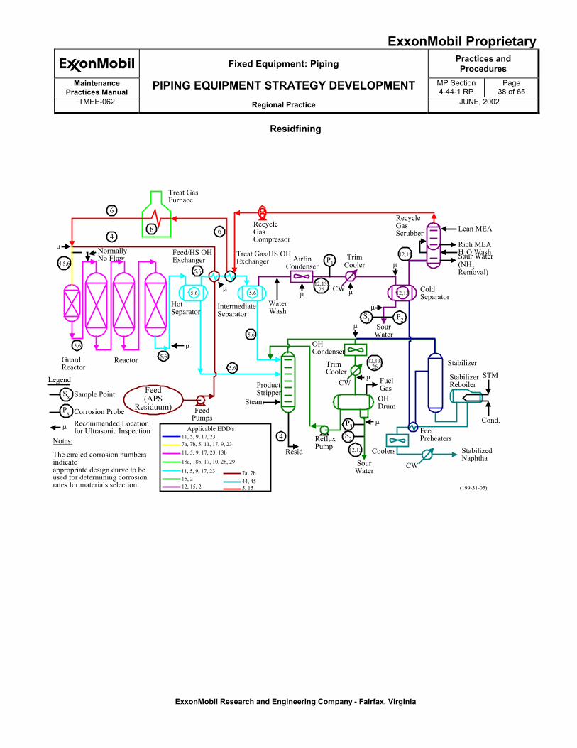
Residfining
Treat GasFurnace
RecycleGasCompressor
Treat Gas/HS OHExchanger
IntermediateSeparator
WaterWash
AirfinCondenser
NormallyNo Flow
6
48 6
5,6
5,6 5,6
HotSeparator
5,6
5,6
5,6Reactor
5,6
GuardReactor
4,5,6
�
Feed(APS
Residuum) FeedPumps
ProductStripper
Steam
4
Resid
RefluxPump
P3
S2
12,13
SourWater
Coolers
�
�� �
�
�
�
CW
FeedPreheaters
StabilizedNaphtha
Cond.
STMStabilizerReboiler
Stabilizer
FuelGas
OHDrum
CW
12,13,26
OHCondenser
TrimCooler
SourWater
S1 P2
12,13
�
CW12,13,
26
P1Trim
Cooler
ColdSeparator
12,13
RecycleGasScrubber Lean MEA
Rich MEAH2O WashSour Water(NH3Removal)
Px
Sx
Legend
Sample Point
Corrosion Probe
�Recommended Locationfor Ultrasonic Inspection
Notes:
The circled corrosion numbersindicateappropriate design curve to beused for determining corrosionrates for materials selection.
Feed/HS OHExchanger
(199-31-05)
�
5, 1544, 45
11, 5, 9, 17, 237a, 7b, 5, 11, 17, 9, 2311, 5, 9, 17, 23, 13b
11, 5, 9, 17, 23 7a, 7b15, 212, 15, 2
Applicable EDD's
18a, 18b, 17, 10, 28, 29
ExxonMobil ProprietaryFixed Equipment: Piping Practices and
ProceduresMaintenance
Practices ManualPIPING EQUIPMENT STRATEGY DEVELOPMENT MP Section
4-44-1 RPPage
39 of 65TMEE-062 Regional Practice JUNE, 2002
ExxonMobil Research and Engineering Company - Fairfax, Virginia
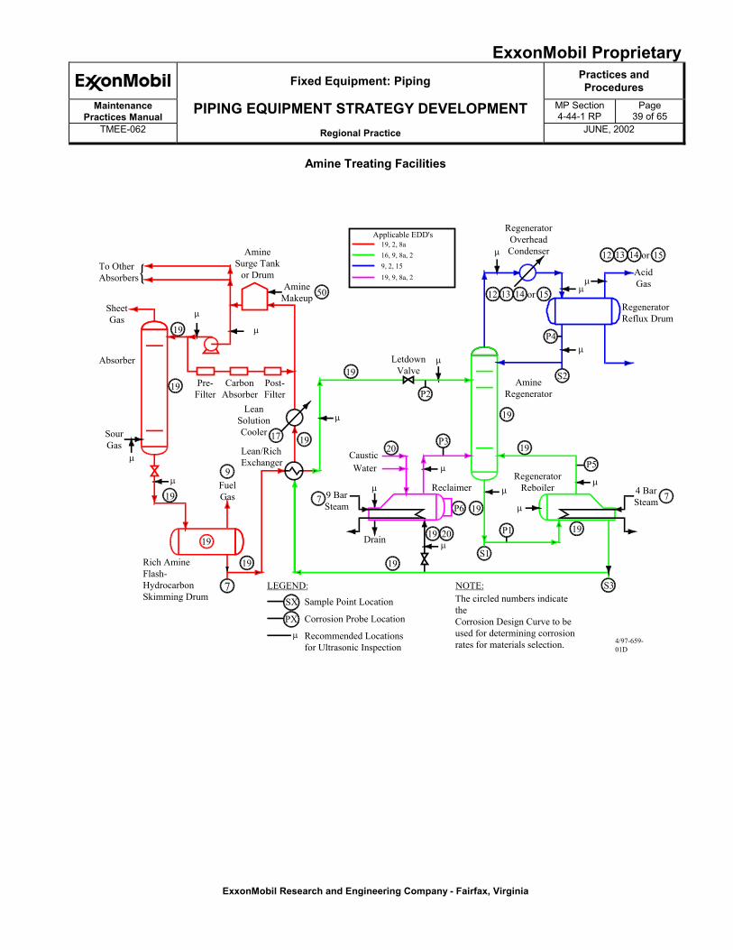
Amine Treating Facilities
19
9
17
7
SX
P2
P3
P5
19
S2
P4
19
19
19
20
20
19P6
19
7
50
7
�
�
�
�
�
�
�
�
�
�
�
�
�
�
�
��
12 13 14 15or
P1
S1
S3
Rich AmineFlash-HydrocarbonSkimming Drum
FuelGas
SourGas
Absorber
SheetGas
To OtherAbsorbers
Pre-Filter
CarbonAbsorber
Post-Filter
AmineSurge Tank
or DrumAmine
Makeup
LeanSolutionCooler
Lean/RichExchanger
LetdownValve
AmineRegenerator
RegeneratorOverheadCondenser
AcidGas
RegeneratorReflux Drum
RegeneratorReboiler 4 Bar
SteamReclaimer
Drain
9 BarSteam
CausticWater
PX
Sample Point Location Corrosion Probe Location Recommended Locationsfor Ultrasonic Inspection
LEGEND: NOTE:The circled numbers indicatetheCorrosion Design Curve to beused for determining corrosionrates for materials selection. 4/97-659-
01D
1919
19
19
19
19
12 13 14 15or
19, 2, 8a16, 9, 8a, 29, 2, 1519, 9, 8a, 2
Applicable EDD's
ExxonMobil ProprietaryFixed Equipment: Piping Practices and
ProceduresMaintenance
Practices ManualPIPING EQUIPMENT STRATEGY DEVELOPMENT MP Section
4-44-1 RPPage
40 of 65TMEE-062 Regional Practice JUNE, 2002
ExxonMobil Research and Engineering Company - Fairfax, Virginia
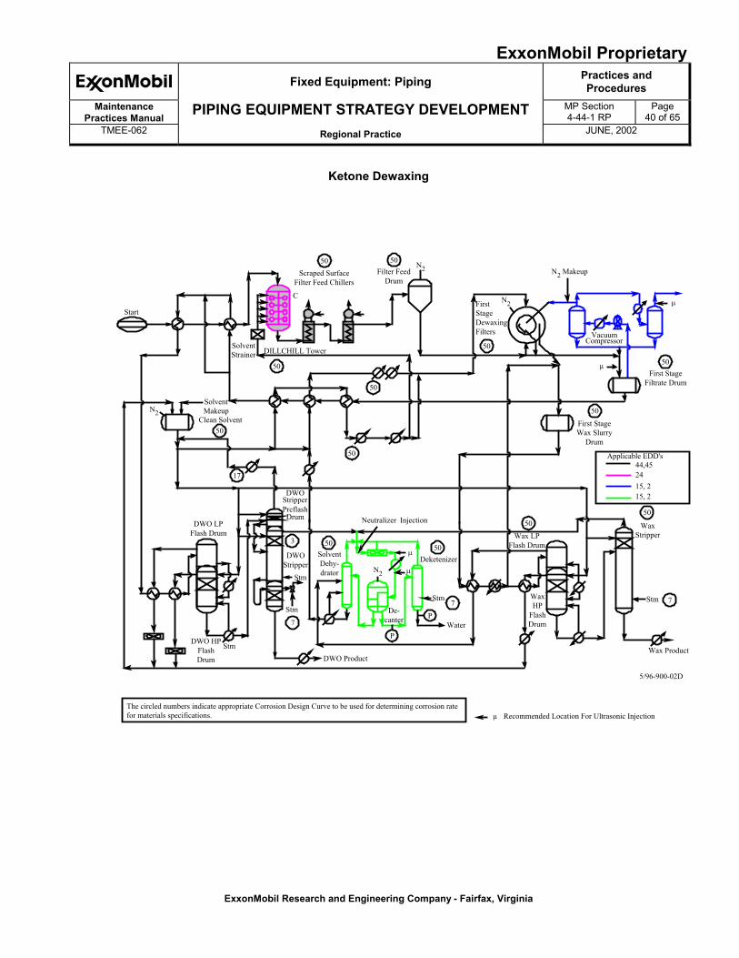
Ketone Dewaxing
Start
SolventStrainer DILLCHILL Tower
Scraped SurfaceFilter Feed Chillers
50
50
50Filter Feed
Drum
N2
C
50
50
FirstStageDewaxingFilters
N2
N2 Makeup
50
�
VacuumCompressor
First StageFiltrate Drum
�
First StageWax Slurry
Drum
50
50
50
17
50
SolventMakeup
Clean SolventN2
DWOStripperPreflashDrum
DWO LPFlash Drum
3 50
7
50
7P
P
50
7
DWO HPFlashDrum
StmDWO Product
Stm
Stm
DWOStripper
SolventDehy-drator
Deketenizer
StmDe-
canterWater
N2 �
Neutralizer Injection
Wax LPFlash Drum
WaxHP
FlashDrum
Stm
Wax Product
WaxStripper
The circled numbers indicate appropriate Corrosion Design Curve to be used for determining corrosion ratefor materials specifications.
�
� Recommended Location For Ultrasonic Injection
5/96-900-02D
44,452415, 215, 2
Applicable EDD's
ExxonMobil ProprietaryFixed Equipment: Piping Practices and
ProceduresMaintenance
Practices ManualPIPING EQUIPMENT STRATEGY DEVELOPMENT MP Section
4-44-1 RPPage
41 of 65TMEE-062 Regional Practice JUNE, 2002
ExxonMobil Research and Engineering Company - Fairfax, Virginia
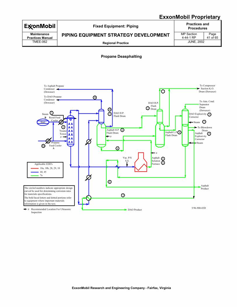
Propane Deasphalting
To Asphalt PropaneCondenser(Dewaxer)
To DAO PropaneCondenser(Dewaxer)
50
50
3
50
4
7
BSteam
Resid FeedCooler
PropaneFeed Cooler
A
Start
TreaterTower�
DAO H.P.Flash Drum
Asphalt H.P.Flash Drum
4
�
4
Vac. P/SS.S.
4
3
DAO ProductRecommended Location For UltrasonicInspection
�
The circled numbers indicate appropriate designcurved be used for determining corrosion ratesfor materials specifications.The bold faced letters and dotted portions referto equipment where important materialsinformation is given in the text.
AsphaltProduct
5/96-900-03D
48
AsphaltSolutionFurnace
�
3
DAO H.P.FlashDrum
Asphalt L.P.Flash Drum
4 4
7
3
To CompressorSuction K.O.
Drum (Dewaxer)
To Atm. Cond.SeparatorDrum(Dewaxer)
DAO ExplosivityCorrector
Steam
Steam
To BlowdownDrum
AsphaltExplosivityCorrector
18a, 18b, 28, 29, 1044, 457a
Applicable EDD's
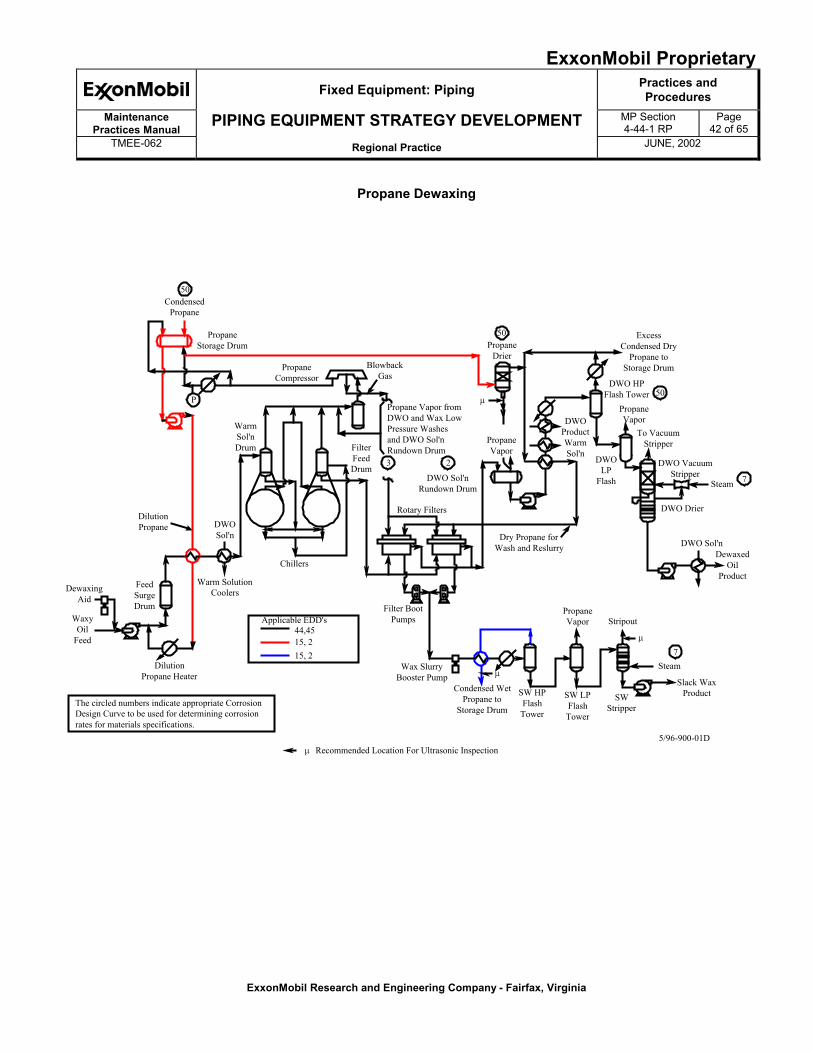
ExxonMobil ProprietaryFixed Equipment: Piping Practices and
ProceduresMaintenance
Practices ManualPIPING EQUIPMENT STRATEGY DEVELOPMENT MP Section
4-44-1 RPPage
42 of 65TMEE-062 Regional Practice JUNE, 2002
ExxonMobil Research and Engineering Company - Fairfax, Virginia
Propane Dewaxing
50Condensed
Propane
PropaneStorage Drum
P
PropaneCompressor
BlowbackGas
Propane Vapor fromDWO and Wax LowPressure Washesand DWO Sol'nRundown Drum
PropaneDrier
50
3 2
DWO Sol'nRundown Drum
FilterFeedDrum
WarmSol'nDrum
DilutionPropane DWO
Sol'n
Warm SolutionCoolers
Chillers
FeedSurgeDrum
DewaxingAid
WaxyOil
Feed
DilutionPropane Heater
The circled numbers indicate appropriate CorrosionDesign Curve to be used for determining corrosionrates for materials specifications.
Filter BootPumps
Wax SlurryBooster Pump
Condensed WetPropane to
Storage Drum
SW HPFlashTower
SW LPFlashTower
SWStripper
PropaneVapor Stripout
Steam
Slack WaxProduct
DewaxedOil
Product
DWO Sol'n
7
7Steam
DWO Drier
DWO VacuumStripper
Dry Propane forWash and Reslurry
Rotary Filters
PropaneVapor
DWOProductWarmSol'n
DWOLP
Flash
To VacuumStripper
PropaneVapor
DWO HPFlash Tower 50
ExcessCondensed Dry
Propane toStorage Drum
�
�
�
� Recommended Location For Ultrasonic Inspection5/96-900-01D
44,4515, 215, 2
Applicable EDD's
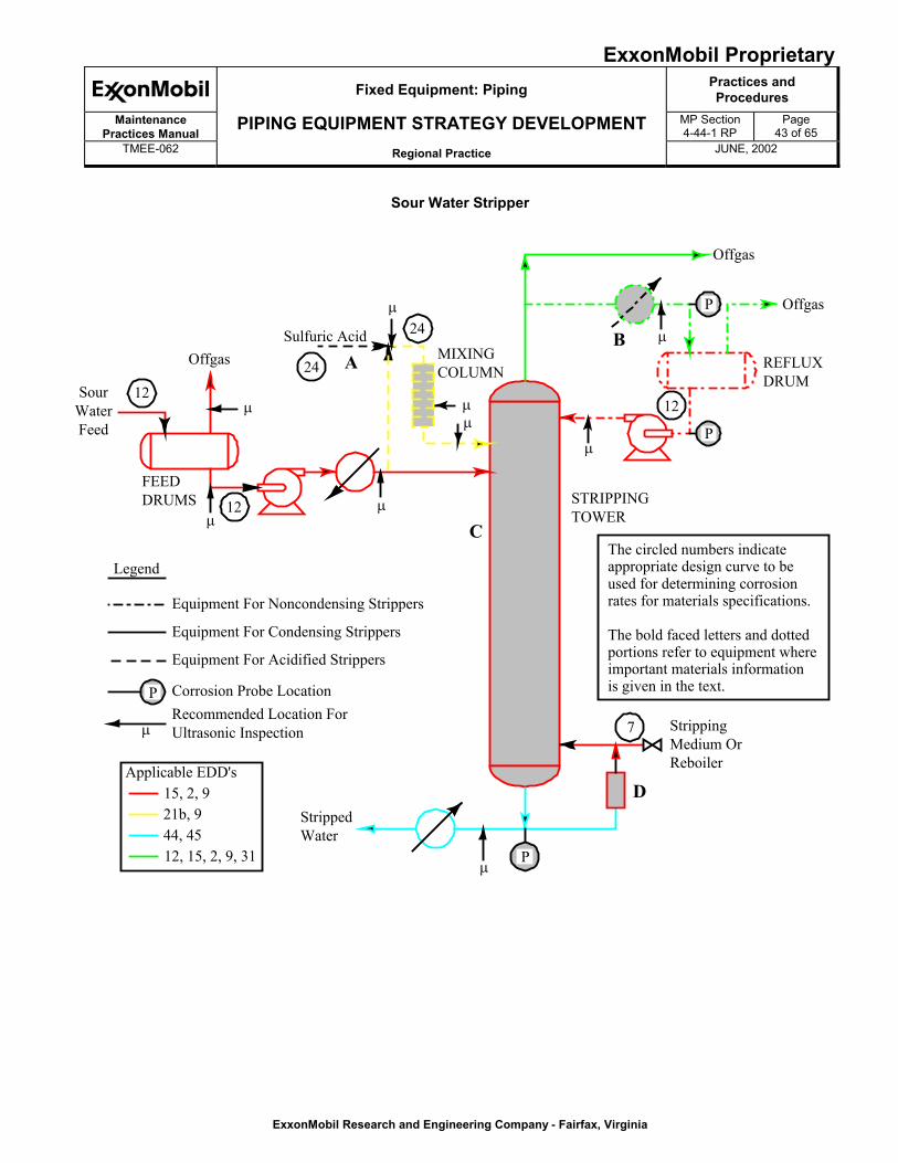
ExxonMobil ProprietaryFixed Equipment: Piping Practices and
ProceduresMaintenance
Practices ManualPIPING EQUIPMENT STRATEGY DEVELOPMENT MP Section
4-44-1 RPPage
43 of 65TMEE-062 Regional Practice JUNE, 2002
ExxonMobil Research and Engineering Company - Fairfax, Virginia
Sour Water Stripper
SourWaterFeed
Offgas
12
FEEDDRUMS
MIXINGCOLUMN
12
24
24Sulfuric Acid
A
C
D
B
STRIPPINGTOWER
REFLUXDRUM
StrippedWater
StrippingMedium OrReboiler
7
P
P
P
Offgas
Offgas
12
The circled numbers indicateappropriate design curve to beused for determining corrosionrates for materials specifications.
The bold faced letters and dottedportions refer to equipment whereimportant materials informationis given in the text.
�
�
�
�
�
�
�
�
�
Legend
Equipment For Noncondensing Strippers
Equipment For Condensing Strippers
Equipment For Acidified Strippers
Corrosion Probe LocationRecommended Location ForUltrasonic Inspection
P
�
15, 2, 921b, 944, 4512, 15, 2, 9, 31
Applicable EDD's
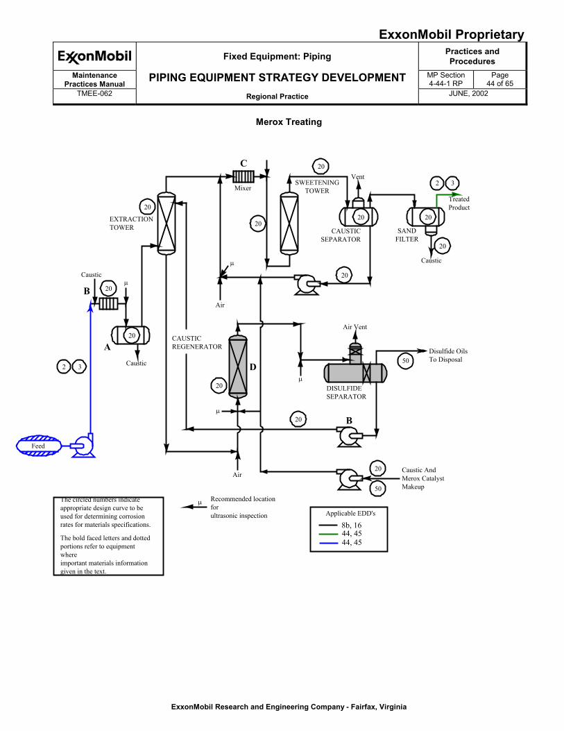
ExxonMobil ProprietaryFixed Equipment: Piping Practices and
ProceduresMaintenance
Practices ManualPIPING EQUIPMENT STRATEGY DEVELOPMENT MP Section
4-44-1 RPPage
44 of 65TMEE-062 Regional Practice JUNE, 2002
ExxonMobil Research and Engineering Company - Fairfax, Virginia
Merox Treating
Feed
2 3 Caustic
Caustic
20
20
B
A
20
EXTRACTIONTOWER
CAUSTICREGENERATOR
Air
20
Mixer
C
20
20
SWEETENINGTOWER
20
20
CAUSTICSEPARATOR
Vent
SANDFILTER
TreatedProduct
20
2 3
20
Caustic
Air Vent
50Disulfide OilsTo Disposal
DISULFIDESEPARATOR
D
B20
20
50
Caustic AndMerox CatalystMakeup
Air
�
�
�
�
�Recommended locationforultrasonic inspection
The circled numbers indicateappropriate design curve to beused for determining corrosionrates for materials specifications.
The bold faced letters and dottedportions refer to equipmentwhereimportant materials informationgiven in the text.
8b, 1644, 4544, 45
Applicable EDD's
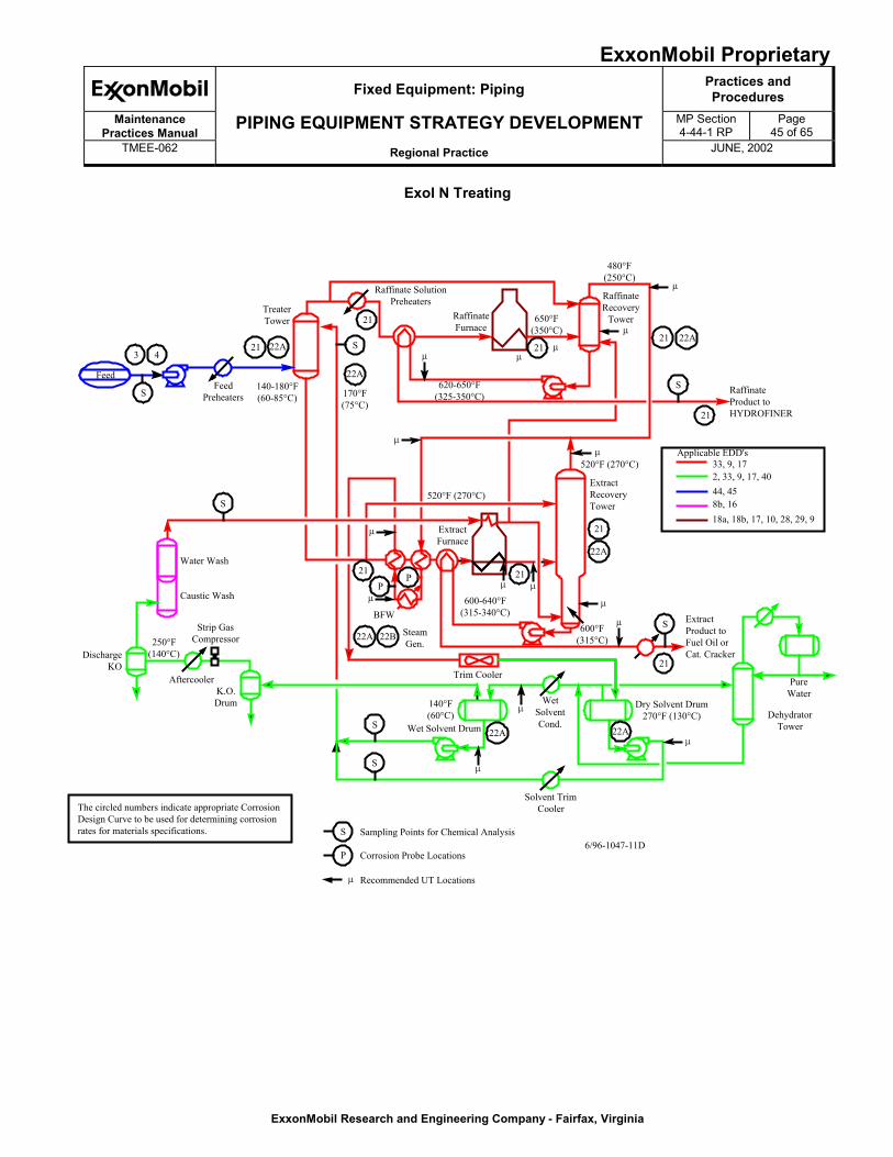
ExxonMobil ProprietaryFixed Equipment: Piping Practices and
ProceduresMaintenance
Practices ManualPIPING EQUIPMENT STRATEGY DEVELOPMENT MP Section
4-44-1 RPPage
45 of 65TMEE-062 Regional Practice JUNE, 2002
ExxonMobil Research and Engineering Company - Fairfax, Virginia
Exol N Treating
Feed
170°F(75°C)
S
3 4
TreaterTower
140-180°F(60-85°C)
21 22A
S
P6/96-1047-11D
The circled numbers indicate appropriate CorrosionDesign Curve to be used for determining corrosionrates for materials specifications. Sampling Points for Chemical Analysis
Corrosion Probe Locations
Recommended UT Locations�
FeedPreheaters
22A
S
21
Raffinate SolutionPreheaters
RaffinateFurnace
S
Water Wash
Caustic Wash
Strip GasCompressor
DischargeKO
250°F(140°C)
AftercoolerK.O.Drum
S
S
140°F(60°C)
Wet Solvent Drum 22A
WetSolventCond.
Solvent TrimCooler
22A 22B SteamGen.
Trim Cooler
ExtractFurnace
21P
P 21
21
22A
600°F(315°C)
600-640°F(315-340°C)
520°F (270°C)
ExtractRecoveryTower
650°F(350°C)
620-650°F(325-350°C)
21
480°F(250°C)
RaffinateRecovery
Tower
21 22A
21
S RaffinateProduct toHYDROFINER
ExtractProduct toFuel Oil orCat. Cracker
21
S
PureWater
DehydratorTower
Dry Solvent Drum270°F (130°C)
22A
�
�
�
�
�
��
�
�
�
� �
�
�
�
�
BFW
520°F (270°C)
33, 9, 172, 33, 9, 17, 4044, 458b, 16
Applicable EDD's
18a, 18b, 17, 10, 28, 29, 9
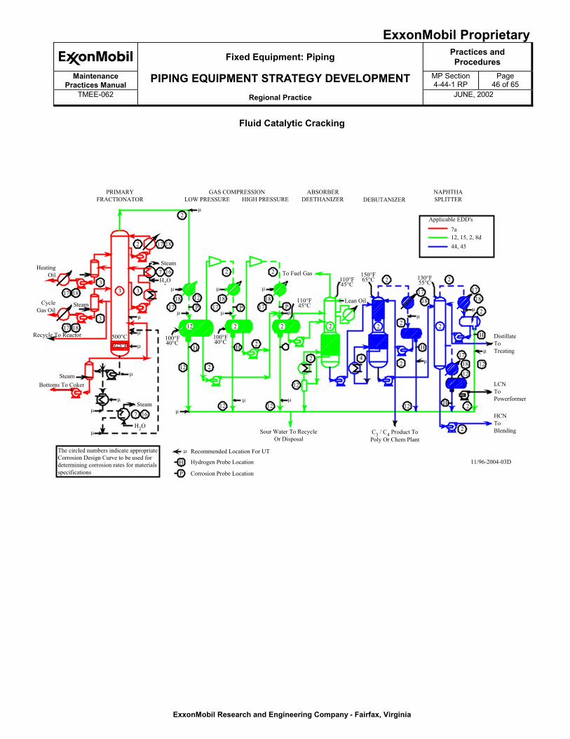
ExxonMobil ProprietaryFixed Equipment: Piping Practices and
ProceduresMaintenance
Practices ManualPIPING EQUIPMENT STRATEGY DEVELOPMENT MP Section
4-44-1 RPPage
46 of 65TMEE-062 Regional Practice JUNE, 2002
ExxonMobil Research and Engineering Company - Fairfax, Virginia
Fluid Catalytic Cracking
�
�
�
�
�
�
�
�
�
�
�
�
�
�
� �
�
�
�
�
�
�
17 18
33 3
317 18
7 16
7 16
17 182
1718 12
12
H
P
2
12 12
12
2
2H
P P1718
1718
22
2
4
2
2
2
2
12
H
H
2
2
2
1718
1718
H
1212
2
2
1718
H
PRIMARYFRACTIONATOR
GAS COMPRESSIONLOW PRESSURE HIGH PRESSURE
2
ABSORBERDEETHANIZER DEBUTANIZER
NAPHTHASPLITTER
HeatingOil
SteamCycleGas Oil
Recycle To Reactor
Steam
H2O
SteamBottoms To Coker
Steam
H2O
500°C 100°F40°C
100°F40°C
110°F45°C
110°F45°C
150°F65°C 130°F
55°CTo Fuel Gas
Lean Oil
Sour Water To RecycleOr Disposal
C3 / C4 Product ToPoly Or Chem Plant
DistillateToTreating
LCNToPowerformer
HCNToBlending
11/96-2004-03D
The circled numbers indicate appropriateCorrosion Design Curve to be used fordetermining corrosion rates for materialsspecifications
Recommended Location For UT
Hydrogen Probe Location
P Corrosion Probe Location
925°F
12 2 2
7a12, 15, 2, 8d44, 45
Applicable EDD's
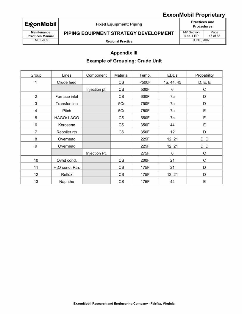
ExxonMobil ProprietaryFixed Equipment: Piping Practices and
ProceduresMaintenance
Practices ManualPIPING EQUIPMENT STRATEGY DEVELOPMENT MP Section
4-44-1 RPPage
47 of 65TMEE-062 Regional Practice JUNE, 2002
ExxonMobil Research and Engineering Company - Fairfax, Virginia
Appendix IIIExample of Grouping: Crude Unit
Group Lines Component Material Temp. EDDs Probability
Crude feed CS <500F 1a, 44, 45 D, E, E1
Injection pt. CS 500F 6 C
2 Furnace inlet CS 600F 7a D
3 Transfer line 5Cr 750F 7a D
4 Pitch 5Cr 750F 7a E
5 HAGO/ LAGO CS 550F 7a E
6 Kerosene CS 350F 44 E
7 Reboiler rtn CS 350F 12 D
8 Overhead 225F 12, 21 D, D
Overhead 225F 12, 21 D, D9
Injection Pt. 275F 6 C
10 Ovhd cond. CS 200F 21 C
11 H2O cond. Rtn. CS 175F 21 D
12 Reflux CS 175F 12, 21 D
13 Naphtha CS 175F 44 E
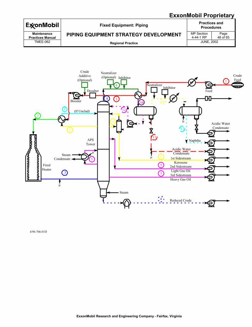
ExxonMobil ProprietaryFixed Equipment: Piping Practices and
ProceduresMaintenance
Practices ManualPIPING EQUIPMENT STRATEGY DEVELOPMENT MP Section
4-44-1 RPPage
48 of 65TMEE-062 Regional Practice JUNE, 2002
ExxonMobil Research and Engineering Company - Fairfax, Virginia
2
6
6
5
3
4
5
5
6
11
8 1
1
12
9
10
�
�
�
�
FiredHeater
CondensateSteam
APSTower
Steam
(If Unclad)
Booster
Desalter
CrudeAdditive
(Optional)
Neutralizer(Optional) Inhibitor
NeutralizerInhibitor
Feed
CrudeFeed
Acidic WaterCondensate
Naphtha
Acidic WaterCondensate
1st SidestreamKerosene
2nd SidestreamLight Gas Oil
3rd SidestreamHeavy Gas Oil
Reduced Crude
4/96-706-01D
7
14
13
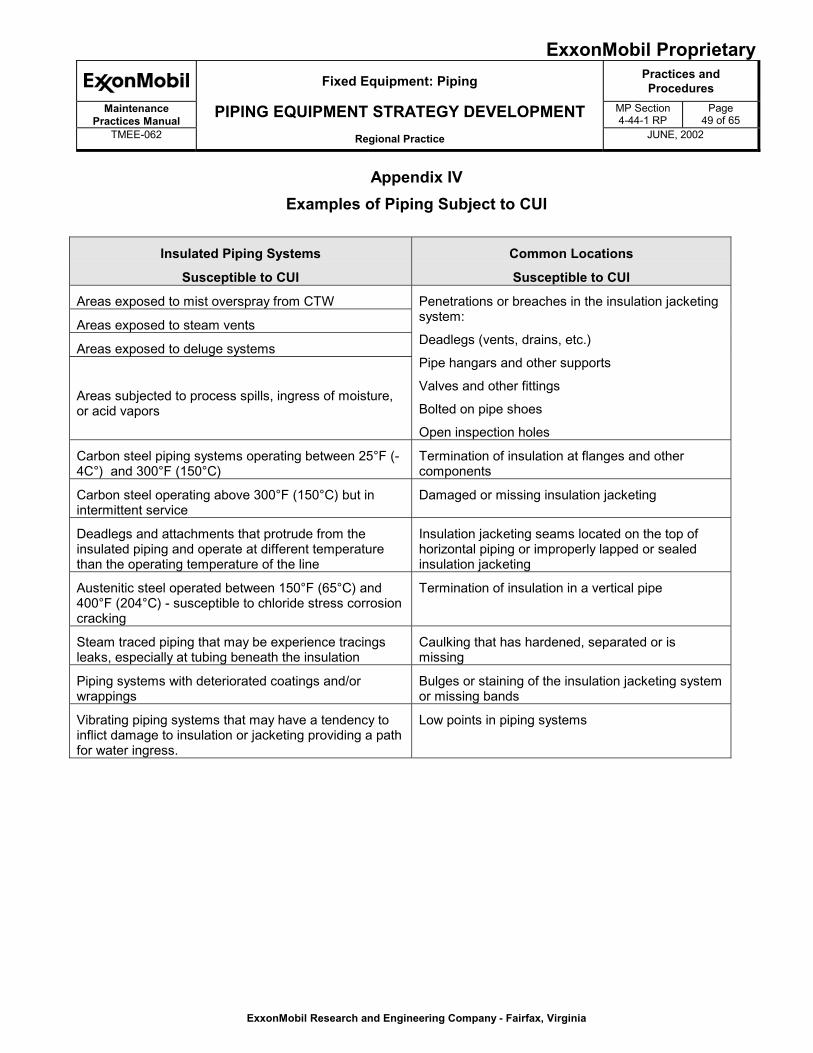
ExxonMobil ProprietaryFixed Equipment: Piping Practices and
ProceduresMaintenance
Practices ManualPIPING EQUIPMENT STRATEGY DEVELOPMENT MP Section
4-44-1 RPPage
49 of 65TMEE-062 Regional Practice JUNE, 2002
ExxonMobil Research and Engineering Company - Fairfax, Virginia
Appendix IVExamples of Piping Subject to CUI
Insulated Piping Systems
Susceptible to CUI
Common Locations
Susceptible to CUI
Areas exposed to mist overspray from CTW
Areas exposed to steam vents
Areas exposed to deluge systems
Areas subjected to process spills, ingress of moisture,or acid vapors
Penetrations or breaches in the insulation jacketingsystem:
Deadlegs (vents, drains, etc.)
Pipe hangars and other supports
Valves and other fittings
Bolted on pipe shoes
Open inspection holes
Carbon steel piping systems operating between 25°F (-4C°) and 300°F (150°C)
Termination of insulation at flanges and othercomponents
Carbon steel operating above 300°F (150°C) but inintermittent service
Damaged or missing insulation jacketing
Deadlegs and attachments that protrude from theinsulated piping and operate at different temperaturethan the operating temperature of the line
Insulation jacketing seams located on the top ofhorizontal piping or improperly lapped or sealedinsulation jacketing
Austenitic steel operated between 150°F (65°C) and400°F (204°C) - susceptible to chloride stress corrosioncracking
Termination of insulation in a vertical pipe
Steam traced piping that may be experience tracingsleaks, especially at tubing beneath the insulation
Caulking that has hardened, separated or ismissing
Piping systems with deteriorated coatings and/orwrappings
Bulges or staining of the insulation jacketing systemor missing bands
Vibrating piping systems that may have a tendency toinflict damage to insulation or jacketing providing a pathfor water ingress.
Low points in piping systems
ExxonMobil ProprietaryFixed Equipment: Piping Practices and
ProceduresMaintenance
Practices ManualPIPING EQUIPMENT STRATEGY DEVELOPMENT MP Section
4-44-1 RPPage
50 of 65TMEE-062 Regional Practice JUNE, 2002
ExxonMobil Research and Engineering Company - Fairfax, Virginia
APPENDIX VERIM 12.3.2 Injection Points
1.0 SCOPE
This procedure is a guideline for external inspection of insulated carbon and low alloy steel pressurevessels, piping, and tanks subject to corrosion under insulation (CUI) and corrosion under fireproofing(CUF). This procedure describes what equipment is subject to CUI and CUF, available inspectiontechniques, suspect areas for CUI/CUF, and extent of inspection.
This procedure does not cover inspection intervals. Inspections are normally conducted at the same intervalas the visual external inspection for the equipment. Refer to documents FEQA 5.6 and FEQA 5.7 for moreinformation on inspection intervals. This procedure also does not cover stress corrosion cracking (SCC) ofstainless steel equipment.
2.0 APPLICATION
This procedure applies to the Inspection personnel responsible for planning and conducting CUI and CUFinspections.
3.0 REFERENCE DOCUMENTS
CE.16.82 - Thermal Insulation Guidelines For Design, Installation and Inspection to ControlCorrosion Under Insulation
Materials Engineering Guide, Section III - Corrosion Under Insulation (CUI)
API 510 - American Petroleum Institute, Pressure Vessel Inspection Code
API 570 - American Petroleum Institute, Piping Inspection Code
ERIM 7.0.1 - Piping Classification
FEQA 5.6 - Pressure Vessel and Piping Inspection Intervals
FEQA 5.7 - Tank Inspection Intervals
FEQA 5.8 - Miscellaneous Equipment Inspection Intervals
MIP 1 - Corrosion Under Insulation (CUI), External Atmospheric Corrosion and Corrosion UnderFireproofing (CUF)
EE.55E.78 - Corrosion of Insulated or Fireproofed Carbon and Stainless Steel
ExxonMobil ProprietaryFixed Equipment: Piping Practices and
ProceduresMaintenance
Practices ManualPIPING EQUIPMENT STRATEGY DEVELOPMENT MP Section
4-44-1 RPPage
51 of 65TMEE-062 Regional Practice JUNE, 2002
ExxonMobil Research and Engineering Company - Fairfax, Virginia
4.0 INTRODUCTION:
Two mechanisms for the deterioration of chemical and refinery equipment are corrosion under insulation(CUI) and corrosion under fireproofing (CUF). CUI/CUF requires prolonged exposure to the presence ofwater against unprotected steel. The primary causes for CUI and CUF are poor design details, improperinstallation, deterioration or damage to the weather/vapor barrier, and the deterioration or lack of aneffective coating on the steel. Quality control (QC) of the installation and inspection and maintenance of theinsulation system and coating are the most important practices in minimizing CUI and CUF damage.
The objective of this procedure is to provide guidelines that enhance the ability of the Inspector and contractNDE examiner to plan and inspect for CUI and CUF. The extent of assurance that all damage will be foundwill depend on the number of critical details exposed for inspection and the inspection of any damage to itslimits.
5.0 DEFINITIONS
Corrosion Under Fireproofing (CUF) Inspection: A specific type of external inspection conducted onequipment covered with fireproofing. Removal of part or all of the fireproofing to gain access to the externalsurface of the equipment may be required.
Corrosion Under Insulation (CUI) Inspection: A specific type of external inspection conducted oninsulated equipment which normally operates between 25�F and 300�F. Removal of part or all of theinsulation to gain access to the external surface of the equipment may be required.
Suspect Areas: Locations where CUI or CUF are most likely to occur. See paragraph 6.2 for examples.
6.0 PROCEDURE
6.1 Identify Equipment Subject to CUI/CUF
6.1.1 Insulated or fireproofed equipment and piping which normally (more than 10% of the time) operate(not design) between 25�F and 300�F, cycle into this range on a continual basis, or which operateoutside this range but are in intermittent service, should be considered subject to CUI or CUF.
6.1.2 Attention should be given to inspecting equipment and piping at attachments when they operatewithin 50�F above the upper or below the lower temperature limits for CUI/CUF. Such locations areincluded in this program. This is due to the possibility that heat transfer along the attachment willbring the actual metal temperature back into the CUI/CUF range.
6.1.3 Insulated or fireproofed equipment and piping that is exposed to process condensate/water orcooling tower overspray are more susceptible to CUI/CUF.
ExxonMobil ProprietaryFixed Equipment: Piping Practices and
ProceduresMaintenance
Practices ManualPIPING EQUIPMENT STRATEGY DEVELOPMENT MP Section
4-44-1 RPPage
52 of 65TMEE-062 Regional Practice JUNE, 2002
ExxonMobil Research and Engineering Company - Fairfax, Virginia
6.1.4 Care should be taken to identify portions of equipment or branches of piping where the actual metaltemperature is within the CUI/CUF temperature range due to stagnant or low flow, or auto-refrigeration while the normal operating temperature is outside the range. Examples where this canoccur include:
� Heads of vessels where the inlet or outlet piping is a significant distance from the heads
� Safety valve inlet piping
� Instrument or analyzer take-off piping
� Flash zone across control valves or orifices
� Bypass piping around exchangers pressure vessels, or control valves
6.2 Identify Suspect Areas for CUI/CUF and Perform Visual Inspection
6.2.1 Identify all areas of damaged insulation.
6.2.2 Identity all suspect areas. Attachments 12.3.4.2 through 12.3.4.5 illustrate suspect areas onvessels, tanks, and piping which can allow entrance of water, impede drainage, trap water, orpromote wicking where CUI/CUF is most likely to occur. These include, but are not limited to:
� Areas adjacent to damaged insulation or joint seals
� Insulation and stiffening rings
� Nozzles and manways
� Attachments such as brackets, supports, ladders and stairways
� Low points in insulation system
� Support lugs and lifting attachments
� Vessel to skirt transition
� Instrument and small pipe connections, including gussets
� Insulated equipment and piping exposed to a constant source of free water, cooling tower mist,condensation or water traps
� Field welds where hand painting is missing or the quality is often poor
� Termination of insulation at flanges and other piping components, especially in the verticalplane
� Areas improperly capped or sealed and above where caulking is hardened, separated, ormissing
� Bulges or staining of insulation or jacketing
ExxonMobil ProprietaryFixed Equipment: Piping Practices and
ProceduresMaintenance
Practices ManualPIPING EQUIPMENT STRATEGY DEVELOPMENT MP Section
4-44-1 RPPage
53 of 65TMEE-062 Regional Practice JUNE, 2002
ExxonMobil Research and Engineering Company - Fairfax, Virginia
6.2.3 Update or draw all isometrics, marking areas to inspect.
6.3 Extent of CUI/CUF Inspection
6.3.1 For piping, the extent for first time CUI inspection shall be based on the requirements of API 570,Piping Inspection Code.
6.3.2 The extent of CUI inspection on pressure vessels and tanks and subsequent CUI inspection onpiping shall be based on the condition of the paint and insulation system, previous inspectionhistory, and the associated risk as defined by the Material Integrity Program (MIP 4). This exerciseis typically done as part of the equipment plan development.
6.3.3 Equipment subject to CUI should be completely stripped of insulation and re-painted when the paintsystem shows signs of moderate deterioration. The timing and scope of this work depends on thedegree of deterioration and the degree of risk.
6.3.4 Sound concrete over 1.5" thick is normally sufficient to protect against CUF. Concrete should beremoved for visual inspection of CUF when signs of cracking, delamination, bulging, or rust stainsare visible.
6.3.5 Intervals for CUI inspection should normally meet the criteria for external visual inspection perFEQA 5.6 and FEQA 5.7. Adjustment of intervals may be required based on the equipmentcondition as determined by inspection.
6.4 Inspection Techniques
6.4.1 On initial installation and whenever modifications or repairs occur, appropriate quality control, perERIM 9.28.1, should be conducted to ensure the weather proofing and coating quality areacceptable.
6.4.2 Visual and radiographic testing (RT) are common inspection techniques used to detect CUI, butseveral other technologies are available that offer benefits of reduced inspection costs or greaterinspection coverage. Attachment 12.3.4.1 summarizes the currently accepted used inspectiontechniques with comments on best use, limitations, and approximate cost.
6.4.3 CUF detection normally relies on visible signs of concrete cracking and rust stains. CUF normallyprogresses from openings (e.g., top of skirt or where a steel column exits the concrete).
ExxonMobil ProprietaryFixed Equipment: Piping Practices and
ProceduresMaintenance
Practices ManualPIPING EQUIPMENT STRATEGY DEVELOPMENT MP Section
4-44-1 RPPage
54 of 65TMEE-062 Regional Practice JUNE, 2002
ExxonMobil Research and Engineering Company - Fairfax, Virginia
6.5 Documentation and Follow-up
6.5.1 Documentation of CUI/CUF inspections in the Inspection Data Management System (IDMS) shouldinclude identification of areas inspected, type of inspection, equipment condition as determined byinspection, and recommended repairs.
6.5.2 A report to the Operating Team should include all work items and recommended timing based onseverity, operating limitations, and scheduled downtimes.
ExxonMobil ProprietaryFixed Equipment: Piping Practices and
ProceduresMaintenance
Practices ManualPIPING EQUIPMENT STRATEGY DEVELOPMENT MP Section
4-44-1 RPPage
55 of 65TMEE-062 Regional Practice JUNE, 2002
ExxonMobil Research and Engineering Company - Fairfax, Virginia
Appendix VIERIM 12.3.1 Mix Points
SCOPE
1.0 This procedure addresses the inspection requirements of process mix points.
2.0 APPLICATION
This procedure applies to inspectors, engineers, materials engineers, and nondestructive examination(NDE) technicians involved in the inspection and thickness measurements of process mix points.
3.0 REFERENCE DOCUMENTS
API 570 - Piping Inspection Code
Refinery Construction Materials Manual (RCMM)
4.0 INTRODUCTION OF MIX POINT INSPECTION PROGRAM
A variety of process mix points exists in a refinery. The majority of these do not contribute to increasedcorrosion and only need to be addressed as part of regular component inspection in a piping circuit.However, some mix points may contribute to accelerated corrosion requiring a more thorough inspection.The latter can be defined as “any location where two or more process streams intersect and where thecorrosion and degradation of the piping system in the location where the streams are mixing together canbe greater than that in the piping of the individual streams or the fully mixed streams”.
A clear distinction should be made between injection points and mix points. Injection points are addressedin API 570 and in various company documents. They typically involve the injection of small quantities of achemical (neutralizers, filmers, caustic, or acids) for corrosion control or pH adjustment, or injection of waterfor dilution of contaminants or dissolving of salt deposits. Mix points for the purpose of this program includebut are not limited to, the mixing of hydrocarbon with hydrocarbon, hydrogen with hydrocarbon, acids withhydrocarbon, caustic with hydrocarbon, hydrogen with hydrogen, and steam with hydrocarbon.
ExxonMobil ProprietaryFixed Equipment: Piping Practices and
ProceduresMaintenance
Practices ManualPIPING EQUIPMENT STRATEGY DEVELOPMENT MP Section
4-44-1 RPPage
56 of 65TMEE-062 Regional Practice JUNE, 2002
ExxonMobil Research and Engineering Company - Fairfax, Virginia
4.1 Historical Experiences with Mix Points
The determination of those characteristics which contribute to a mix point being corrosive is difficult.However, ExxonMobil and industry experience has been reviewed to identify mix points that havecontributed to problems in the past. These locations form the starting point for an effective affiliateinspection program. The list shown in paragraph 4.6 summarizes many of the known areas of concern.
4.2 Determining Mix Points to be Examined
4.2.1 As illustrated in paragraph 4.6, the corrosiveness at a mix point may be enhanced by a variety offactors including:
� Vaporization of water/concentration of corrosives
� Acid/aqueous phase condensation
� Temperature differences contributing to thermal fatigue
� Turbulence
4.2.2 Because of the problems experienced by ExxonMobil and industry, it is recommended that initialinspection emphasis focus on the following areas:
� Mixing of hydrocarbon streams from hot and cold separators in hydrotreating units
Note: Alloyed mixing tees (Hastelloy, Inconel, etc.) typically do not require inspectionhowever, inspection of the associated piping is required as indicated below.
� Tie-ins involving hydrogen, light ends, or naphtha streams containing HCl from CatalyticReforming Units (Powerforming, Hydroforming, CCR) with wet streams from other units likecrude units
� Hot and cold hydrogen junctions at the hydrocracker
� Bypasses around exchangers in which the downstream piping at the bypass of the exchanger isof a lower metallurgy than the piping upstream of the exchanger
Note: Process needs to provide input as to whether or not such bypasses are used.
ExxonMobil ProprietaryFixed Equipment: Piping Practices and
ProceduresMaintenance
Practices ManualPIPING EQUIPMENT STRATEGY DEVELOPMENT MP Section
4-44-1 RPPage
57 of 65TMEE-062 Regional Practice JUNE, 2002
ExxonMobil Research and Engineering Company - Fairfax, Virginia
� Hydrogen addition points in hydrotreater circuits where the hydrocarbon (feed) piping exhibitsgeneral corrosion rates greater than 30 mpy
� Hydrogen addition points where sour recycled hydrogen is being injected into piping fabricatedfrom materials other than austenitic stainless steel
� Tie-ins involving recycled acid and alkylate feed in sulfuric acid alkylation units
� Tie-ins involving compressor recycle pressure balance lines into atmospheric pipestill doubledrum overhead piping
� Steam mixing points into piping exposed to a sulfidizing environment at temperatures in excessof 550 degrees F.
4.3 Determining Appropriate Type of Inspection
Corrosion at mix points is often localized and is unlikely to be detected with conventional spot ultrasonicthickness readings. Consequently, a detailed inspection effort involving radiography and/or ultrasonic testing(UT) (automated ultrasonics, UT grid mapping on a tightly defined grid pattern or scrubbing) is required toensure that isolated problems are not overlooked.
4.4 Determining How Much Inspection is Needed
4.4.1 Corrosion associated with mix points is expected to occur over a broader area than just the actualfitting where mixing occurs. Consequently, following the approach of API 570 for injection points, itis suggested that a "mixing point circuit" be identified for inspection. This circuit should extend froma point that is the greater of 12” or 1 pipe diameter upstream of the actual mixing point fitting in boththe branch and run piping up to and including the fitting at the first change in flow directiondownstream of the mixing streams.
Note: the "mix point" is considered to be the actual fitting where differing streams join together. Thisis typically a tee but may involve an elbow, a Y connection, or an internal pipe distributor.
4.4.2 Mix Points Where Corrosion Loss is Expected
Corrosion loss at mix points can occur in a variety of services including those subjected tosulfidation, naphthenic acid corrosion, and H2S/H2 corrosion. When the mixing occurs in a fittingsuch as a tee, specific recommendations for inspection within such mix point circuits follow:
ExxonMobil ProprietaryFixed Equipment: Piping Practices and
ProceduresMaintenance
Practices ManualPIPING EQUIPMENT STRATEGY DEVELOPMENT MP Section
4-44-1 RPPage
58 of 65TMEE-062 Regional Practice JUNE, 2002
ExxonMobil Research and Engineering Company - Fairfax, Virginia
Other mixing point configurations require a thorough examination in the general location of initialmixing, and all components upstream per the requirements given in 4.4.2.a, and downstream perthe requirements given in 4.4.2.c & d.
a) Initiate inspection at the upstream limit of the circuit - a minimum of 12 inches or 1 pipediameter ahead of the mix point whichever is greater.
b) Examine the mix point fitting. A thorough examination of the entire fitting is recommended.This should include an inspection of the "crotch" area of the fitting immediately adjacent toboth the upstream and the downstream side of the tie-in between the branch and runpiping. Fittings with reinforcing pads require the use of radiography in lieu of ultrasonics.The inspection should also encompass the area immediately adjacent to the circumferentialbutt welds in both the fitting and the mating piping.
Note: The initial mixing point is located where an internal distributor pipe terminates whenone exists.
c) Examine the piping at one diameter, two diameter, and ten diameter intervals downstreamfrom the mix point fitting. Additional inspection may be warranted if branch connectionsexist within 10 pipe diameters downstream of the mix point fitting.
d) Examine the first fitting downstream from the mix point where the flow direction changes.
Note 1. In services where condensing HCl is possible, the extent of inspection should be expandedto include piping to the second change in flow direction or to 25 feet beyond the first change in flowdirection, whichever is less. Long straight runs of piping prior to the first change in flow directionshould be examined at 5 pipe diameter intervals for the greater of the remainder of the first 20 pipediameters or 25 feet beyond the injection point.
4.4.3 Mix Points Where Thermal Fatigue is Expected
The mixing of two streams whose temperatures differ by more than 300�F can lead to cracking ofthe mix point fitting due to thermal fatigue. For mix points that are subjected to thermal fatigue butare not subject tom mix point corrosion only the mix point fitting requires inspection. Ultrasonicshearwave inspection along with external magnetic particle or dye penetrant inspection are thepreferred techniques to detect cracking in such fittings. Fittings with reinforcing pads may requireremoval of the pad during downtimes to facilitate this inspection.
Note: The use of internal alloy thermal shields has been demonstrated as an effective measure tominimize the potential of thermal fatigue cracking.
ExxonMobil ProprietaryFixed Equipment: Piping Practices and
ProceduresMaintenance
Practices ManualPIPING EQUIPMENT STRATEGY DEVELOPMENT MP Section
4-44-1 RPPage
59 of 65TMEE-062 Regional Practice JUNE, 2002
ExxonMobil Research and Engineering Company - Fairfax, Virginia
4.4.4 Mix Points Where There is a Potential for Hydrogen Attack
When there is some potential of elevated temperature hydrogen attack at a mix point, inspectiontechniques should rely on a combination of ultrasonic backscatter technology, velocity ratiotechniques, and ultrasonic attenuation. This inspection should be focused primarily on materialadjacent to welds since residual fabrication stresses can increase a materials susceptibility tohydrogen attack.
4.5 Inspection Intervals
Industry guidelines for the re-inspection of mix points are currently not available. However, the requirementsof API 570 for injection points form a good starting point for defining re-inspection intervals.
a. For newly installed mix points, experience with similar material in comparable service may be used toestablish the projected corrosion rate.
b. Where owner/user experience is not available or where published data on corrosion rates are notavailable, the initial inspection should be performed within (no greater than) 6 months of operation.
c. When localized corrosion is found, full repeat surveys shall be carried out at the lesser of 3 years orhalf the remaining life.
d. Where no localized corrosion is found after 2 complete surveys, monitor with piping circuit. If operatingenvelope changes, evaluate the need to reinstate the inspection program.
4.6 Industry/ExxonMobil Experience with Mix Point Corrosion
See 12.3.1.1
ExxonMobil ProprietaryFixed Equipment: Piping Practices and
ProceduresMaintenance
Practices ManualPIPING EQUIPMENT STRATEGY DEVELOPMENT MP Section
4-44-1 RPPage
60 of 65TMEE-062 Regional Practice JUNE, 2002
ExxonMobil Research and Engineering Company - Fairfax, Virginia
Appendix VIIERIM 12.3.3 Stagnant Zones and Deadlegs
1.0 SCOPE
This procedure addresses the inspection requirements for sections of piping systems subjected to little orno flow (stagnant zones and deadlegs).
2.0 APPLICATION
This procedure applies to inspectors, engineers, metallurgists, and nondestructive examination (NDE)technicians involved in the inspection and thickness inspections of stagnant zones and deadlegs.
3.0 REFERENCE DOCUMENTS
API 570 - Piping Inspection Code
4.0 INTRODUCTION
Three recent affiliate incidents associated with piping having little or no flow have highlighted the need for acircuit program focused on stagnant zone inspection. The need for such a program is emphasized in API570, the Piping Inspection Code. It advocates the inspection of piping systems containing deadlegs, e.g.,stagnant zones. This procedure is intended to provide a consistent set of guidelines for use within eachaffiliate.
Stagnant zones and deadlegs are sections of piping with little or no flow. When such locations are createdby closure of a valve or installation of a blind, they are open referred to as process deadlegs or stagnantzones. Examples of stagnant zones include control valve bypasses and piping used only for startup andshutdown. Locations of piping configurations that contain permanent areas with little or no flow are typicallyreferred to as deadlegs.
Exxon affiliates have experienced corrosion problems associated with both stagnant zones and deadlegs.One of the most significant problems involved a major fire at the Cat Light Ends Unit at the Bayway Refineryin 1979. This fire was attributed to internal corrosion of a deadleg which was functioning as a pipe support.The incident prompted a circuit-wide response to identify, inspect, and eliminate possible deadlegs in areassubjected to internal corrosion. Some affiliates additionally implemented a similar effort directed at stagnantzones. See also EE.37E.80, Guidelines for the Evaluation of Deadlegs in Refinery Piping Systems.
ExxonMobil ProprietaryFixed Equipment: Piping Practices and
ProceduresMaintenance
Practices ManualPIPING EQUIPMENT STRATEGY DEVELOPMENT MP Section
4-44-1 RPPage
61 of 65TMEE-062 Regional Practice JUNE, 2002
ExxonMobil Research and Engineering Company - Fairfax, Virginia
Three recent affiliate incidents have heightened our awareness and concern for problems in stagnantzones. The first occurred in mid 1995 and involved HCl condensate corrosion of short piping branchconnections to safety valves in an overhead pipestill at Baytown. Even though these were identified beforeonstream leakage occurred, the connections required on-line installation of leak repair clamps in order tocontinue unit operation. The second incident also occurred at Baytown in 1995 when corrosion occurred inpiping directly ahead of a bank of exchangers in a pipestill overhead circuit The bank had been intentionallyisolated by closing a valve. This created an approximately 8 foot long stagnant zone between the valve andthe main overhead piping to the other exchangers. Corrosion in this stagnant zone led to a pitting failureattributed to acidic condensate which resulted in a unit shutdown to replace the piping. The third incidentoccurred at Baton Rouge in 1996 in a seldom-used bypass around an exchanger in a pipestill preheatexchanger train upstream of the desalter. This incident resulted in leakage due to corrosion beneath saltdeposits and also led to an unscheduled unit outage.
Problems with stagnant zones have also been recently experienced in industry. In 1996 the Shell Refinery inMartinez, California, experienced a leak and a significant fire in a cat feed hydrofining unit (CFHU). Thisleak and fire occurred in a heat exchanger bypass. The process piping going into the shellside of thisexchanger contained both recycled hydrogen from the CFHU and hydrogen from the catalytic reforming unit(Powerforming type service). It was concluded that the temperatures were cool enough in the bypass line. toallow corrosive ammonium chloride salts to form which resulted in the corrosion. Another incident at thisrefinery with stagnant zone corrosion was reported in EE Technology Alert EE.2TA.89. Attachment 12.3.3.1includes a summary of the 1989 incident as well as information relating to other similar problems in industry.
5.0 INSPECTION PROGRAM
The following three elements should be considered in the creation of an inspection program to addressstagnant zone corrosion.
5.1 Identification of Stagnant Zones
5.1.1 A number of piping configurations create stagnant zones. These include:
� Equipment bypasses
� Safety valve inlet and outlet piping
� Pumpout lines
� Startup and shutdown lines
� Piping around and to spared equipment (e.g., Pumps)
� Piping in intermittent service
� Idled and decommissioned lines
� Piping to instruments such as gage glasses or level controllers
� Small bore high point and low point connections
ExxonMobil ProprietaryFixed Equipment: Piping Practices and
ProceduresMaintenance
Practices ManualPIPING EQUIPMENT STRATEGY DEVELOPMENT MP Section
4-44-1 RPPage
62 of 65TMEE-062 Regional Practice JUNE, 2002
ExxonMobil Research and Engineering Company - Fairfax, Virginia
5.1.2 For the purposes of this program, it is recommended that any piping exposed to low flow or no flowconditions that is longer than 8" or 1 1/2 times its diameter, whichever is greater, before the valve orblind, be considered a candidate for stagnant zone corrosion. While many stagnant zones are likelyto be relatively short,10 feet or less, bypasses around equipment and startup and shutdown linesmay be up to hundreds of feet in length. When long stagnant zones are identified, arecommendation for redesign should be made to Operations.
5.2 Prioritizing Stagnant Zones for Inspection
5.2.1 Not every stagnant zone is expected to be corrosive, and special emphasis on stagnant zones in allservices is not warranted. To assist in inspection priority, it is suggested that stagnant zones berated on a risk basis, that is, rated based on the probability and consequence of a leak. As indicatedabove by the recent affiliate problems, the potential for corrosion (highest probability) is likely tooccur in circuits prone to the condensation of corrosives or the collection of deposits in a corrosiveenvironment. The Materials Integrity Program (MlPs)developed as part of the MISS initiative definesconditions that contribute to stagnant zone corrosion in MIP 4, Deadleg Corrosion. It indicates thatservices likely to lead to corrosive conditions include piping where deposits and/or water can collectand contribute to underdeposit corrosion and piping where corrosive condensate/ streams cancollect or form.
5.2.2 Piping where deposits and/or water can collect and contribute to under-deposit corrosion includesareas such as:
� Sour water services where sulfide scale can collect
� Crude preheat trains where BS&W can collect (normally upstream of the desalter)
� APS overheads end hydrotreater hot separator overhead services where corrosiveammonia/amine salts may form
5.2.3 Piping where a corrosive condensate/streams can collect or form include areas such as:
� APS overheads
� FCCU/Coker fractionator overheads
� Crude Light Ends (Saturated Light Ends), Cat Light Ends, and Coker Light Ends ( wet gascompressor suction and discharge piping and tower overhead circuits)
� Hydrotreater product stripper overheads
� Hydrotreater reactor effluent trains/separator overhead systems
� Sour water stripper overheads
� Amine regenerator tower overheads
� Powerformer regeneration piping/streams containing chlorides
� Alkylation Unit acid and emulsion lines
ExxonMobil ProprietaryFixed Equipment: Piping Practices and
ProceduresMaintenance
Practices ManualPIPING EQUIPMENT STRATEGY DEVELOPMENT MP Section
4-44-1 RPPage
63 of 65TMEE-062 Regional Practice JUNE, 2002
ExxonMobil Research and Engineering Company - Fairfax, Virginia
Using this information, a methodology to rank stagnant zones based on risk can be developedusing ERE guidelines contained in the Material Integrity Programs - Applications of Risk BasedInspection. Once the prioritized list is developed, Operations should review it to determine if any ofthe stagnant zones can be eliminated from the unit.
5.3 Conducting the Inspection
The selected inspection approach should maximize the potential for identifying localized corrosion. As withother inspection initiatives that are focused on the identification of localized metal loss, the actual programshould rely on detailed ultrasonic examination (area scrubbing or closely defined grids) and/or radiography.Spot ultrasonic thickness measurements are not effective for identification of the localized corrosionexpected in such services.
5.4 Recommended Inspection Procedures
5.4.1 The following procedures are suggested for initial inspection of stagnant piping systems. Theseprocedures can be adjusted once corrosion patterns have been established.
5.4.2 For horizontal runs, it is recommended that inspection be initially directed to the lower portion (6o'clock position) of the piping. Continuous ultrasonic scanning along the lower section of the line isrecommended. To complement the continuous scan, ultrasonics (or radiography) should be used toscan the horizontal run in bands at one foot intervals. Special emphasis should be given to any lowpoint in the stagnant zone and areas adjacent to any attachment or structure that may act as acooling fin and promote local condensation. See Attachment 12.3.3.2.
5.4.3 For vertical runs extending downward to the valve or blinding point, inspection should initially focuson the low point in the system. Ultrasonics or radiography in two planes is recommended forinspection of an area equivalent to at least two branch pipe diameters. If a water level can beidentified in the piping, attempts should be made to determine the liquid-to-vapor interface region.This may be an area prone to accelerated corrosion due to alternate wetting and drying. Ultrasonicsor radiography should be used to scan the balance of the vertical leg in bands at one foot intervals.The crotch area where the stagnant zone piping (branch) joins the live line should also be examinedfor at least one pipe diameter upstream and downstream of the branch connection. See Attachment12.3.3.3.
Note: Stress corrosion cracking of austenitic stainless steel piping was experienced at a water-to-vapor interface at Baytown due to concentration of chlorides at the interface. Areas consideredsusceptible to SCC should be assessed using ultrasonic shearwave examination.
5.4.4 For vertical runs extending upwards towards the valve or blinding point, ultrasonics or radiographyshould be used to scan the vertical leg in bands at one foot intervals. The run piping (live line)where the stagnant zone piping branches upward should be examined for at least one run pipediameter upstream and downstream of the branch connection. As noted above for horizontal piping,areas adjacent to external attachments in vertical runs (vertical up or vertical down) may be prone
ExxonMobil ProprietaryFixed Equipment: Piping Practices and
ProceduresMaintenance
Practices ManualPIPING EQUIPMENT STRATEGY DEVELOPMENT MP Section
4-44-1 RPPage
64 of 65TMEE-062 Regional Practice JUNE, 2002
ExxonMobil Research and Engineering Company - Fairfax, Virginia
to localized cooling and subsequent condensation of the line contents. These areas should receivespecial inspection emphasis. See Attachment 12.3.3.4.
5.4.5 For stagnant zones, it is recommended that the greater of the first 10 pipe diameters or 10 feet beinspected as above. The balance of the piping should be inspected at 5 pipe diameter intervals forthe greater of the first 20 pipe diameters or 25 feet beyond the live line. Additionally, any other lowpoints in the stagnant zone "circuit” where moisture or deposits could collect should be inspected.
5.4.6 While internal corrosion is the main focus of this inspection program, insulated stagnant zones arealso potentially subjected to corrosion under insulation (CUI) if the stagnant zone operates attemperatures less than 250�F. The stagnant zone inspection program needs to address inspectionfor CUI. Application of a proper external coating system should help minimize future CUI concernsand may permit deferral of future inspections. Following inspection it may be economical over thelong term to reinsulate such piping with removable replaceable insulation to save maintenancedollars in the future.
5.5 Implementation of the Inspection Program
It is expected that there are thousands of stagnant zones in a refinery. To assist in the implementation of aprogram of such size, it is recommended that it be implemented in phases with initial emphasis on thehighest priority units in the plant. Unit prioritization is expected to differ between sites and needs to bedetermined at a local level. Implementation of the program can be aligned with the refinery HAZOPschedule to ensure that the data is available for inclusion in the Unit Materials Reviews scheduled for theunit.
5.6 Record Keeping and Scheduling
5.6.1 Stagnant zones selected for inspection should be uniquely identified in IDMS and on the unit pipingisometrics. Following original inspection, it is recommended that stagnant zones be scheduled forreinspection based on the requirements of API 570 or 5 years whichever is less. Stagnant zonesexhibiting high corrosion rates should be examined annually until confidence with predictingremaining life is achieved.
5.6.2 Changes to piping and changes in unit operations (bypassing additional equipment, takingequipment out of service) are expected to occur continuously. A frequent dialogue must bemaintained between Operations and Inspection to stay abreast of these changes. A formal reviewof materials-related issues is recommended and that it includes stagnant zones. The reviewshould be held with Operations on a scheduled basis (perhaps annually) to incorporate anychanges that may impact the stagnant zone inspection program as well as other materials-relatedprograms of interest.
ExxonMobil ProprietaryFixed Equipment: Piping Practices and
ProceduresMaintenance
Practices ManualPIPING EQUIPMENT STRATEGY DEVELOPMENT MP Section
4-44-1 RPPage
65 of 65TMEE-062 Regional Practice JUNE, 2002
ExxonMobil Research and Engineering Company - Fairfax, Virginia
Revision Memo
March 2002 1 New