Embed Size (px)
Citation preview
EXTRUSION–TECHNICAL GUIDE02
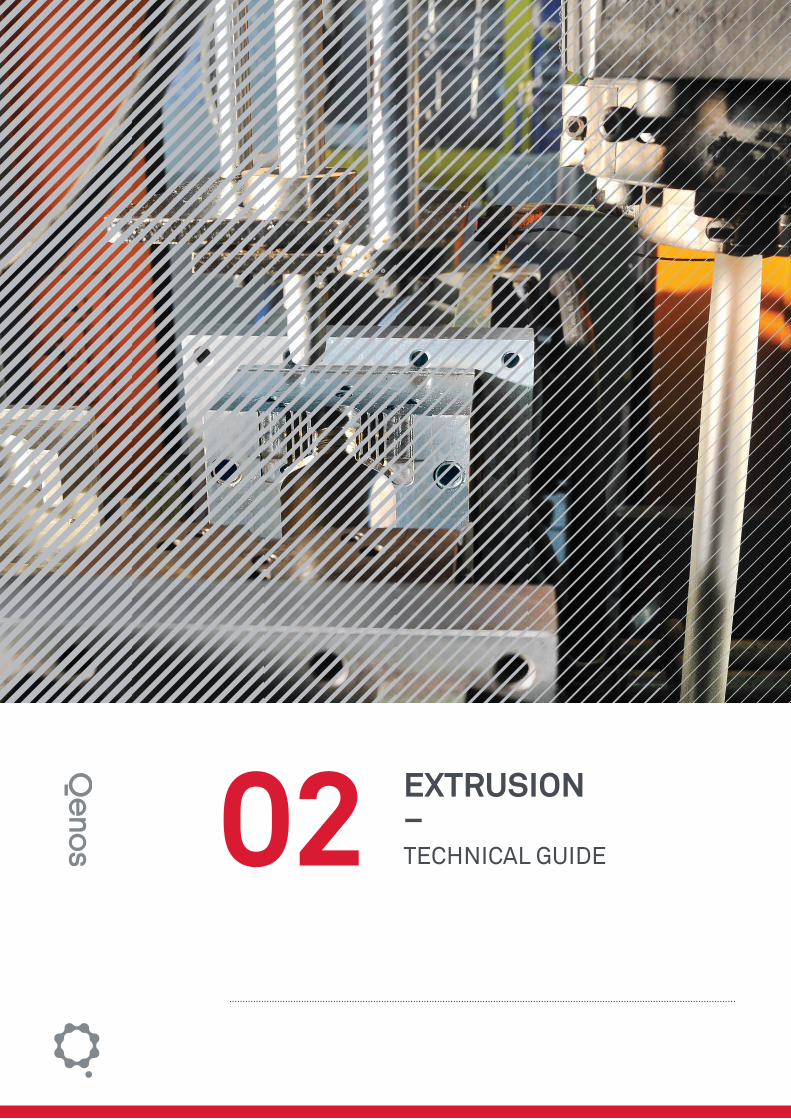
Front CoverThe Qenos Technical Centre operates a range of commercial and laboratory scale extrusion equipment for the injection moulding, blow moulding (pictured), fi lm extrusion and pipe extrusion markets. Qenos employs this capability to fabricate products under real life manufacturing conditions to improve products and processes and to assist customers with their product development and troubleshooting.
Qenos, the Qenos brandmark, Alkathene, Alkatuff, Alkamax, Alkadyne and Alkatane are trade marks of Qenos Pty Ltd.

EXTRUSION 2
2 EXTRUSION
2 Qenos Technical Guides
TABLE OF CONTENTS
INTRODUCTION 3
THE EXTRUSION PROCESS 4
Process Description 4
FEATURES OF THE EXTRUDER 4
The Feed System 4
Extruder Drive System 4
Heating and Cooling the Barrel 4
Temperature Profiles 5
SCREW DESIGN 5
Functions of the Screw 5
Barrier Flighted Screws 6
Mixing Sections 7
Grooved Feed Sections 7
EXTRUSION DIES 8
Functions of the Die 8
Features of the Die 9
Cooling and Shaping the Extrudate 9
Crystallisation 9
Contraction in Volume 10
Orientation in the Melt 10
BIBLIOGRAPHY/FURTHER READING 11

3Qenos Technical Guides
EXTRUSION 2
3Qenos Technical Guides
INTRODUCTION
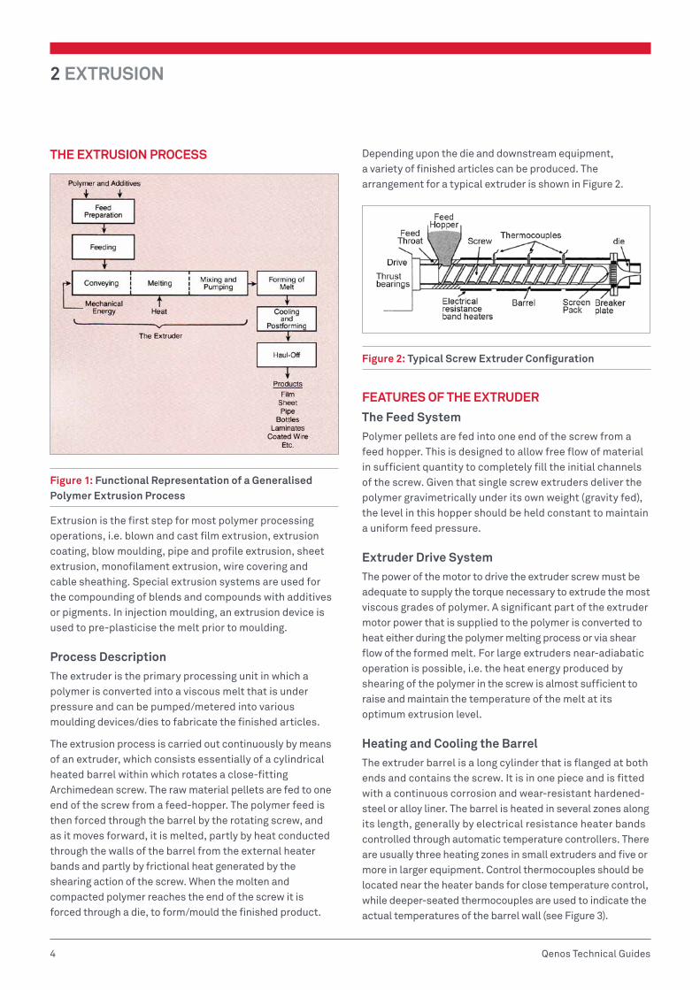
Extrusion is the basic process used in the plastics industry for converting most polymers from a solid pelletised or granular raw material into a homogeneous melt. This melt is delivered at high pressure and at a uniform rate and temperature to the die ready for forming into the final shaped product. A block diagram representation of the extrusion process is given in Figure 1.
Disclaimer
All information contained in this publication and any further information, advice, recommendation or assistance given by Qenos either orally or in writing in relation to the contents of this publication is given in good faith and is believed by Qenos to be as accurate and up-to-date as possible.
The information is offered solely for your information and is not all-inclusive. The user should conduct its own investigations and satisfy itself as to whether the information is relevant to the user’s requirements. The user should not rely upon the information in any way. The information shall not be construed as representations of any outcome. Qenos expressly disclaims liability for any loss, damage, or injury (including any loss arising out of negligence) directly or indirectly suffered or incurred as a result of or related to anyone using or relying on any of the information, except to the extent Qenos is unable to exclude such liability under any relevant legislation.
Freedom from patent rights must not be assumed.
2 EXTRUSION
4 Qenos Technical Guides
THE EXTRUSION PROCESS
Figure 1: Functional Representation of a Generalised Polymer Extrusion Process
Extrusion is the first step for most polymer processing operations, i.e. blown and cast film extrusion, extrusion coating, blow moulding, pipe and profile extrusion, sheet extrusion, monofilament extrusion, wire covering and cable sheathing. Special extrusion systems are used for the compounding of blends and compounds with additives or pigments. In injection moulding, an extrusion device is used to pre-plasticise the melt prior to moulding.
Process DescriptionThe extruder is the primary processing unit in which a polymer is converted into a viscous melt that is under pressure and can be pumped/metered into various moulding devices/dies to fabricate the finished articles.
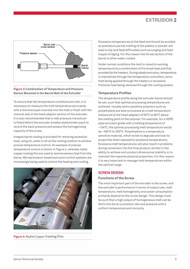
The extrusion process is carried out continuously by means of an extruder, which consists essentially of a cylindrical heated barrel within which rotates a close-fitting Archimedean screw. The raw material pellets are fed to one end of the screw from a feed-hopper. The polymer feed is then forced through the barrel by the rotating screw, and as it moves forward, it is melted, partly by heat conducted through the walls of the barrel from the external heater bands and partly by frictional heat generated by the shearing action of the screw. When the molten and compacted polymer reaches the end of the screw it is forced through a die, to form/mould the finished product.
Depending upon the die and downstream equipment, a variety of finished articles can be produced. The arrangement for a typical extruder is shown in Figure 2.
Figure 2: Typical Screw Extruder Configuration
FEATURES OF THE EXTRUDER
The Feed SystemPolymer pellets are fed into one end of the screw from a feed hopper. This is designed to allow free flow of material in sufficient quantity to completely fill the initial channels of the screw. Given that single screw extruders deliver the polymer gravimetrically under its own weight (gravity fed), the level in this hopper should be held constant to maintain a uniform feed pressure.
Extruder Drive SystemThe power of the motor to drive the extruder screw must be adequate to supply the torque necessary to extrude the most viscous grades of polymer. A significant part of the extruder motor power that is supplied to the polymer is converted to heat either during the polymer melting process or via shear flow of the formed melt. For large extruders near-adiabatic operation is possible, i.e. the heat energy produced by shearing of the polymer in the screw is almost sufficient to raise and maintain the temperature of the melt at its optimum extrusion level.
Heating and Cooling the BarrelThe extruder barrel is a long cylinder that is flanged at both ends and contains the screw. It is in one piece and is fitted with a continuous corrosion and wear-resistant hardened-steel or alloy liner. The barrel is heated in several zones along its length, generally by electrical resistance heater bands controlled through automatic temperature controllers. There are usually three heating zones in small extruders and five or more in larger equipment. Control thermocouples should be located near the heater bands for close temperature control, while deeper-seated thermocouples are used to indicate the actual temperatures of the barrel wall (see Figure 3).
EXTRUSION 2
5Qenos Technical Guides
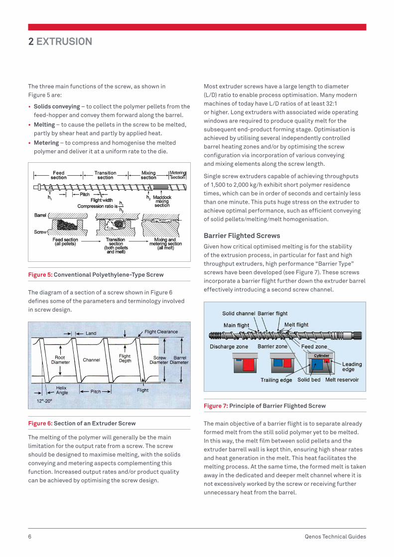
Figure 3: Combination of Temperature and Pressure Sensor Mounted in the Barrel Wall of the Extruder
To ensure that the temperature conditions are met, it is necessary to measure the melt temperature accurately with a thermocouple inserted into the melt or flush with the channel wall in the head adaptor section of the extruder. It is also recommended that a melt pressure transducer is fitted before the extruder breaker plate/screen pack to record the back pressure and assess the homogenising capacity of the screw.
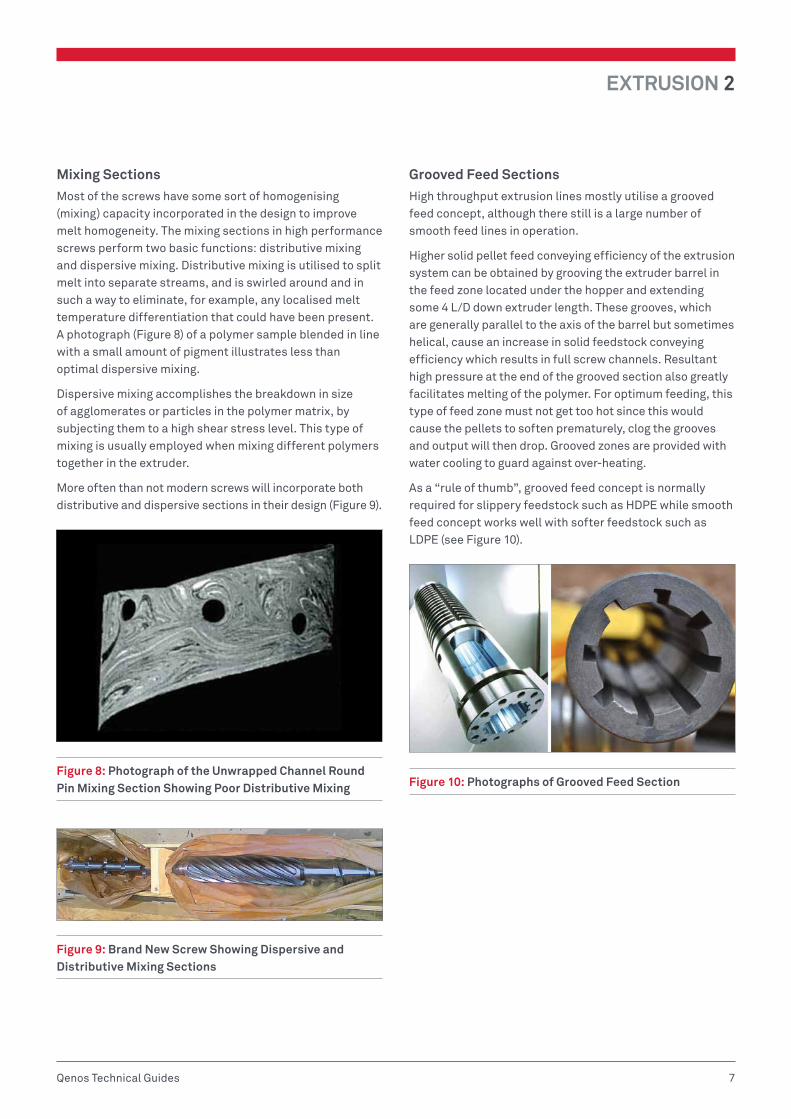
Integral barrel cooling is provided for removing excessive heat, using oil, water or air as the cooling medium to achieve precise temperature control. An example of precise temperature control is shown in Figure 4, whereby radial copper cooling fins are used to remove excess heat from the barrel. Microprocessor-based extrusion control systems are increasingly being used to control the heating and cooling.
Figure 4: Radial Copper Cooling Fins
Excessive temperatures at the feed end should be avoided, as premature partial melting of the pellets or powder will lead to slip and feed difficulties such as surging and feed hopper bridging. For this reason the throat section of the barrel is often water-cooled.
Under normal conditions the melt is raised to working temperature by a combination of frictional heat and that provided by the heaters. During steady extrusion, temperature is maintained through the temperature controllers; extra heat being applied through the heaters or excessive frictional heat being removed through the cooling system.
Temperature ProfilesThe temperature profile along the extruder barrel should be set, such that optimal processing temperatures are achieved. Usually semicrystalline polymers such as polyethylene are best processed at a melt temperature (measured at the head adapter) of 50°C to 60°C above the melting point of the polymer. For example, for a HDPE pipe extrusion grade with a melting temperature of ~134°C, the optimal processing melt temperature would be ~190°C to 200°C. Polyethylene is a temperature sensitive material, which tends to degrade and lose its properties when exposed to excessive temperatures. Excessive melt temperatures will also result in problems during conversion into the final product, be that in the ability to achieve end-product dimensional stability or to maintain the required physical properties. For this reason it is very important to manage melt temperatures within the optimal range.
SCREW DESIGN
Functions of the ScrewThe most important part of the extruder is the screw, and the extruder’s performance in terms of output rate, melt temperature, melt homogeneity and power consumption primarily depend on the screw design. This design must be such that a high output of homogeneous melt can be fed to the die at a constant rate and pressure with a uniform temperature and viscosity.
2 EXTRUSION
6 Qenos Technical Guides
The three main functions of the screw, as shown in Figure 5 are:
• Solids conveying – to collect the polymer pellets from the feed-hopper and convey them forward along the barrel.
• Melting – to cause the pellets in the screw to be melted, partly by shear heat and partly by applied heat.
• Metering – to compress and homogenise the melted polymer and deliver it at a uniform rate to the die.
Figure 5: Conventional Polyethylene-Type Screw
The diagram of a section of a screw shown in Figure 6 defines some of the parameters and terminology involved in screw design.
Figure 6: Section of an Extruder Screw
The melting of the polymer will generally be the main limitation for the output rate from a screw. The screw should be designed to maximise melting, with the solids conveying and metering aspects complementing this function. Increased output rates and/or product quality can be achieved by optimising the screw design.
Most extruder screws have a large length to diameter (L/D) ratio to enable process optimisation. Many modern machines of today have L/D ratios of at least 32:1 or higher. Long extruders with associated wide operating windows are required to produce quality melt for the subsequent end-product forming stage. Optimisation is achieved by utilising several independently controlled barrel heating zones and/or by optimising the screw configuration via incorporation of various conveying and mixing elements along the screw length.
Single screw extruders capable of achieving throughputs of 1,500 to 2,000 kg/h exhibit short polymer residence times, which can be in order of seconds and certainly less than one minute. This puts huge stress on the extruder to achieve optimal performance, such as efficient conveying of solid pellets/melting/melt homogenisation.
Barrier Flighted ScrewsGiven how critical optimised melting is for the stability of the extrusion process, in particular for fast and high throughput extruders, high performance “Barrier Type” screws have been developed (see Figure 7). These screws incorporate a barrier flight further down the extruder barrel effectively introducing a second screw channel.
Figure 7: Principle of Barrier Flighted Screw
The main objective of a barrier flight is to separate already formed melt from the still solid polymer yet to be melted. In this way, the melt film between solid pellets and the extruder barrell wall is kept thin, ensuring high shear rates and heat generation in the melt. This heat facilitates the melting process. At the same time, the formed melt is taken away in the dedicated and deeper melt channel where it is not excessively worked by the screw or receiving further unnecessary heat from the barrel.
EXTRUSION 2
7Qenos Technical Guides
Mixing SectionsMost of the screws have some sort of homogenising (mixing) capacity incorporated in the design to improve melt homogeneity. The mixing sections in high performance screws perform two basic functions: distributive mixing and dispersive mixing. Distributive mixing is utilised to split melt into separate streams, and is swirled around and in such a way to eliminate, for example, any localised melt temperature differentiation that could have been present. A photograph (Figure 8) of a polymer sample blended in line with a small amount of pigment illustrates less than optimal dispersive mixing.
Dispersive mixing accomplishes the breakdown in size of agglomerates or particles in the polymer matrix, by subjecting them to a high shear stress level. This type of mixing is usually employed when mixing different polymers together in the extruder.
More often than not modern screws will incorporate both distributive and dispersive sections in their design (Figure 9).
Figure 8: Photograph of the Unwrapped Channel Round Pin Mixing Section Showing Poor Distributive Mixing
Figure 9: Brand New Screw Showing Dispersive and Distributive Mixing Sections
Grooved Feed SectionsHigh throughput extrusion lines mostly utilise a grooved feed concept, although there still is a large number of smooth feed lines in operation.
Higher solid pellet feed conveying efficiency of the extrusion system can be obtained by grooving the extruder barrel in the feed zone located under the hopper and extending some 4 L/D down extruder length. These grooves, which are generally parallel to the axis of the barrel but sometimes helical, cause an increase in solid feedstock conveying efficiency which results in full screw channels. Resultant high pressure at the end of the grooved section also greatly facilitates melting of the polymer. For optimum feeding, this type of feed zone must not get too hot since this would cause the pellets to soften prematurely, clog the grooves and output will then drop. Grooved zones are provided with water cooling to guard against over-heating.
As a “rule of thumb”, grooved feed concept is normally required for slippery feedstock such as HDPE while smooth feed concept works well with softer feedstock such as LDPE (see Figure 10).
Figure 10: Photographs of Grooved Feed Section
2 EXTRUSION
8 Qenos Technical Guides
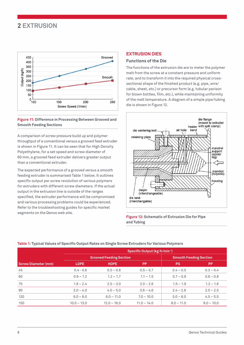
Figure 11: Difference in Processing Between Grooved and Smooth Feeding Sections
A comparison of screw pressure build up and polymer throughput of a conventional versus a grooved feed extruder is shown in Figure 11. It can be seen that for High Density Polyethylene, for a set speed and screw diameter of 60 mm, a grooved feed extruder delivers greater output than a conventional extruder.
The expected performance of a grooved versus a smooth feeding extruder is summarised Table 1 below. It outlines specific output per screw revolution of various polymers for extruders with different screw diameters. If the actual output in the extrusion line is outside of the ranges specified, the extruder performance will be compromised and various processing problems could be experienced. Refer to the troubleshooting guides for specific market segments on the Qenos web site.
EXTRUSION DIES
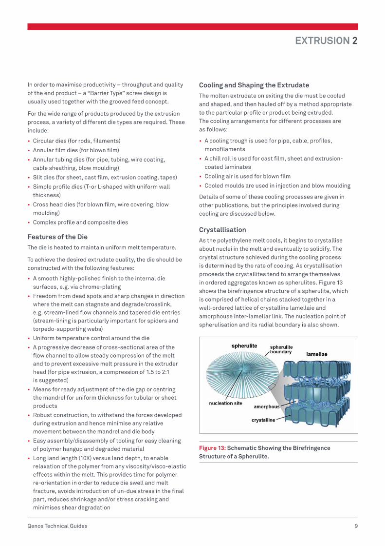
Functions of the DieThe functions of the extrusion die are to meter the polymer melt from the screw at a constant pressure and uniform rate, and to transform it into the required physical cross-sectional shape of the finished product (e.g. pipe, wire/cable, sheet, etc.) or precursor form (e.g. tubular parison for blown bottles, film, etc.), while maintaining uniformity of the melt temperature. A diagram of a simple pipe/tubing die is shown in Figure 12.
Figure 12: Schematic of Extrusion Die for Pipe and Tubing
Table 1: Typical Values of Specific Output Rates on Single Screw Extruders for Various Polymers
Screw Diameter (mm)
Specific Output (kg/h/min-1)
Grooved Feeding Section Smooth Feeding Section
LDPE HDPE PP PS PP
45 0.4 - 0.6 0.5 – 0.8 0.5 – 0.7 0.4 – 0.5 0.3 – 0.4
60 0.9 – 1.2 1.2 – 1.7 1.1 – 1.5 0.7 – 0.9 0.6 – 0.8
75 1.8 – 2.4 2.5 – 3.0 2.0 – 2.6 1.5 – 1.9 1.2 – 1.6
90 3.0 – 4.0 4.0 – 5.0 3.6 – 4.6 2.4 – 2.8 2.0 – 2.5
120 6.0 – 8.0 8.0 – 11.0 7.0 – 10.0 5.0 – 6.0 4.5 – 5.5
150 10.0 – 13.0 12.0 – 16.0 11.0 – 14.0 8.0 – 11.0 8.0 – 10.0
EXTRUSION 2
9Qenos Technical Guides
In order to maximise productivity – throughput and quality of the end product – a “Barrier Type” screw design is usually used together with the grooved feed concept.
For the wide range of products produced by the extrusion process, a variety of different die types are required. These include:
• Circular dies (for rods, filaments)
• Annular film dies (for blown film)
• Annular tubing dies (for pipe, tubing, wire coating, cable sheathing, blow moulding)
• Slit dies (for sheet, cast film, extrusion coating, tapes)
• Simple profile dies (T-or L-shaped with uniform wall thickness)
• Cross head dies (for blown film, wire covering, blow moulding)
• Complex profile and composite dies
Features of the DieThe die is heated to maintain uniform melt temperature.
To achieve the desired extrudate quality, the die should be constructed with the following features:
• A smooth highly-polished finish to the internal die surfaces, e.g. via chrome-plating
• Freedom from dead spots and sharp changes in direction where the melt can stagnate and degrade/crosslink, e.g. stream-lined flow channels and tapered die entries (stream-lining is particularly important for spiders and torpedo-supporting webs)
• Uniform temperature control around the die
• A progressive decrease of cross-sectional area of the flow channel to allow steady compression of the melt and to prevent excessive melt pressure in the extruder head (for pipe extrusion, a compression of 1.5 to 2:1 is suggested)
• Means for ready adjustment of the die gap or centring the mandrel for uniform thickness for tubular or sheet products
• Robust construction, to withstand the forces developed during extrusion and hence minimise any relative movement between the mandrel and die body
• Easy assembly/disassembly of tooling for easy cleaning of polymer hangup and degraded material
• Long land length (10X) versus land depth, to enable relaxation of the polymer from any viscosity/visco-elastic effects within the melt. This provides time for polymer re-orientation in order to reduce die swell and melt fracture, avoids introduction of un-due stress in the final part, reduces shrinkage and/or stress cracking and minimises shear degradation
Cooling and Shaping the ExtrudateThe molten extrudate on exiting the die must be cooled and shaped, and then hauled off by a method appropriate to the particular profile or product being extruded. The cooling arrangements for different processes are as follows:
• A cooling trough is used for pipe, cable, profiles, monofilaments
• A chill roll is used for cast film, sheet and extrusion-coated laminates
• Cooling air is used for blown film
• Cooled moulds are used in injection and blow moulding
Details of some of these cooling processes are given in other publications, but the principles involved during cooling are discussed below.
CrystallisationAs the polyethylene melt cools, it begins to crystallise about nuclei in the melt and eventually to solidify. The crystal structure achieved during the cooling process is determined by the rate of cooling. As crystallisation proceeds the crystallites tend to arrange themselves in ordered aggregates known as spherulites. Figure 13 shows the birefringence structure of a spherulite, which is comprised of helical chains stacked together in a well-ordered lattice of crystalline lamellaie and amorphouse inter-lamellar link. The nucleation point of spherulisation and its radial boundary is also shown.
Figure 13: Schematic Showing the Birefringence Structure of a Spherulite.
2 EXTRUSION
10 Qenos Technical Guides
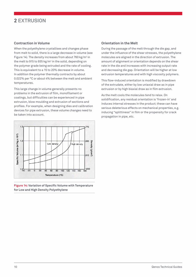
Contraction in VolumeWhen the polyethylene crystallises and changes phase from melt to solid, there is a large decrease in volume (see Figure 14). The density increases from about 760 kg/m3 in the melt to 915 to 935 kg/m3 in the solid, depending on the polymer grade being extruded and the rate of cooling. This is equivalent to a 15 to 20% decrease in volume. In addition the polymer thermally contracts by about 0.022% per °C or about 4% between the melt and ambient temperatures.
This large change in volume generally presents no problems in the extrusion of film, monofilament or coatings, but difficulties can be experienced in pipe extrusion, blow moulding and extrusion of sections and profiles. For example, when designing dies and calibration devices for pipe extrusion, these volume changes need to be taken into account.
Figure 14: Variation of Specific Volume with Temperature for Low and High Density Polyethylene
Orientation in the MeltDuring the passage of the melt through the die gap, and under the influence of the shear stresses, the polyethylene molecules are aligned in the direction of extrusion. The amount of alignment or orientation depends on the shear rate in the die and increases with increasing output rate and decreasing die gap. Orientation will be higher at low extrusion temperatures and with high viscosity polymers.
This flow-induced orientation is modified by drawdown of the extrudate, either by low uniaxial draw as in pipe extrusion or by high biaxial draw as in film extrusion.
As the melt cools the molecules tend to relax. On solidification, any residual orientation is ‘frozen-in’ and induces internal stresses in the product; these can have serious deleterious effects on mechanical properties, e.g. inducing “splittiness” in film or the propensity for crack propagation in pipe, etc.
EXTRUSION 2
11Qenos Technical Guides
BIBLIOGRAPHY/FURTHER READING1. Giles, H. F. Jr.; Eldridge, M. M III.; Wagner, J. R. Jr.; Extrusion: The Definitive Processing Guide and Handbook,
Elsevier Science, 2007.
2. Brydson, J.; Plastic Materials, Elsevier, 1999.
3. Rauwendaal, C.; Polymer Extrusion, Hanser Verlag, 2001.
4. Crawford, R. J.; Plastics Engineering – Processing (3rd Ed.); Elsevier, 1998.
5. Chung, C. I.; Extrusion of Polymers, Theory and Practice, Hanser Verlag, 2000.
6. Hensen, F.; Plastics Extrusion Technology, Hanser Verlag, 1997.
7. White, J. L.; Petente, H.; Screw Extrusion, Hanser Verlag, 2003.
8. White, J. L.; Coran, A. Y.; Moet, A.; Polymer Mixing, Technology and Engineering, Hanser Gardner, 2001.
9. Holton, H. E.; Extrusion Control, Machine – Process – Product, Hanser Verlag, 2004.
10. del Pilar, M.; Noriega, E.; Rauwendaal, C.; Troubleshooting the Extrusion Process – A Systematic Approach to Solving Plastic Extrusion Problems, Hanser Verlag, 2001.
11. Osswald, T.; Hernandez-Ortiz, J. P.; Pablo, J.; Polymer Processing – Modeling and Simulation, Hanser Verlag, 2006.
12. Ezrin, M.; Plastics Failure Guide: Cause and Prevention, Hanser Gardner, 1996.
13. Moalli, J.; Plastics Failure – Analysis and Prevention, William Andrew Publishing, 2001.
14. Ramanathan, M.; Darling, S. B.; Mesoscale morphologies in polymer thin films, Prog in Polym Sci 36, 793, 2011.
Issued July 2015.

Polyethylene Technical Guide Series
POLYETHYLENE BLOW MOULDING –TECHNICAL GUIDE
08PIPE AND TUBING EXTRUSION –TECHNICAL GUIDE
07ROTATIONAL MOULDING–TECHNICAL GUIDE
06INJECTION MOULDING–TECHNICAL GUIDE
05
EXTRUSION COATING & LAMINATION–TECHNICAL GUIDE
04FILM EXTRUSION AND CONVERSION–TECHNICAL GUIDE
03EXTRUSION–TECHNICAL GUIDE02GENERAL
PROPERTIES–TECHNICAL GUIDE
01

Qenos Pty Ltd471 Kororoit Creek RdAltona Victoria 3018 AustraliaPhone 1800 063 573 Fax 1800 638 981ABN 62 054 196 771–qenos.com