Embed Size (px)
Citation preview
Extreme Mechanical Behavior of Nacre-Mimetic Graphene-Oxide andSilk NanocompositesWanting Xie,†,‡ Sirimuvva Tadepalli,§ Sang Hyun Park,§ Amir Kazemi-Moridani,‡ Qisheng Jiang,§
Srikanth Singamaneni,*,§ and Jae-Hwang Lee*,‡
†Department of Physics, University of Massachusetts Amherst, Amherst, Massachusetts 01003, United States‡Department of Mechanical and Industrial Engineering, University of Massachusetts Amherst, Amherst, Massachusetts 01003, UnitedStates§Department of Mechanical Engineering and Materials Science and Institute of Materials Science and Engineering, WashingtonUniversity in St. Louis, St. Louis, Missouri 63130, United States
*S Supporting Information
ABSTRACT: Biological materials have the ability to with-stand extreme mechanical forces due to their unique multilevelhierarchical structure. Here, we fabricated a nacre-mimeticnanocomposite comprised of silk fibroin and graphene oxidethat exhibits hybridized dynamic responses arising fromalternating high-contrast mechanical properties of thecomponents at the nanoscale. Dynamic mechanical behaviorof these nanocomposites is assessed through a microscaleballistic characterization using a 7.6 μm diameter silica spheremoving at a speed of approximately 400 m/s. The volumefraction of graphene oxide in these composites is systematically varied from 0 to 32 vol % to quantify the dynamic effectscorrelating with the structural morphologies of the graphene oxide flakes. Specific penetration energy of the films rapidlyincreases as the distribution of graphene oxide flakes evolves from noninteracting, isolated sheets to a partially overlappingcontinuous sheet. The specific penetration energy of the nanocomposite at the highest graphene oxide content tested here isfound to be significantly higher than that of Kevlar fabrics and close to that of pure multilayer graphene. This study evidentlydemonstrates that the morphologies of nanoscale constituents and their interactions are critical to realize scalable high-performance nanocomposites using typical nanomaterial constituents having finite dimensions.
KEYWORDS: Scalable nanocomposite, penetration dynamics, high strain rate, flexible armor
Nanocomposites comprised of materials with distinctmechanical properties and tailored interfaces between
the components have received wide attention over the last twodecades due to their synergistically improved propertiescompared to the individual components.1−3 Nanocompositesare promising for the development of lightweight ballisticarmor materials, where dissipation of a projectile’s massivekinetic energy with a limited areal density (or mass per unitarea) is required. In contrast to conventional structuralcomposites being used below a material’s yield strength, dueto the extreme nature of mechanical interactions between ahigh-speed projectile and an armor composite, irreversiblestructural damage via dynamic failure processes includingcracking, fragmentation, shear, and delamination are generallyaccompanied.4 In this aspect, typical composites that havemicro- or larger scale material phases still tend to exhibitcharacteristic failure mechanisms of individual constituentmaterials because a material’s intrinsic failure mechanism isgoverned at the submicrometer scale. Therefore, in addition tothe superior load transfer efficiency, which is attributed to thelarge interfacial area between phases,5 composites with
nanoscale phases or nanocomposites exhibit a hybridizedfailure mechanism for enhanced antiballistic performance.As a filler for nanocomposites, graphene oxide (GO) stands
out among reinforcing nanofiller materials due to its attractivecharacteristics, including high elastic modulus (250 GPa),6 lowdensity,7 high water solubility, and good mechanical flexibility.8
As a matrix, we employed silk fibroin (SF), a material thatforms one of the toughest natural fibers, as well as a goodcandidate for both a binder and matrix.9−12 Both componentsof the nanocomposite are amphiphilic, GO comprised ofhydrophobic graphitic and hydrophilic oxidized functionalities;SF also contains both hydrophilic and hydrophobic domains.13
The complementary heterogeneity of GO and SF can maximizevarious noncovalent interactions between the fillers and thematrix. The mechanical performance of materials largelydepends on the interactions at the interface, so maximizing
Received: October 16, 2017Revised: December 19, 2017Published: January 9, 2018
Letter
pubs.acs.org/NanoLettCite This: Nano Lett. 2018, 18, 987−993
© 2018 American Chemical Society 987 DOI: 10.1021/acs.nanolett.7b04421Nano Lett. 2018, 18, 987−993
the interfacial binding is critical for achieving desiredmechanical properties.13
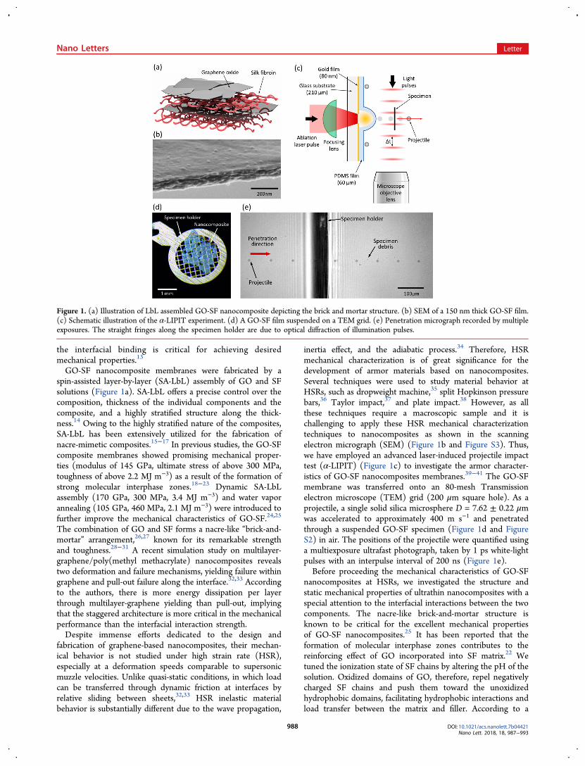
GO-SF nanocomposite membranes were fabricated by aspin-assisted layer-by-layer (SA-LbL) assembly of GO and SFsolutions (Figure 1a). SA-LbL offers a precise control over thecomposition, thickness of the individual components and thecomposite, and a highly stratified structure along the thick-ness.14 Owing to the highly stratified nature of the composites,SA-LbL has been extensively utilized for the fabrication ofnacre-mimetic composites.15−17 In previous studies, the GO-SFcomposite membranes showed promising mechanical proper-ties (modulus of 145 GPa, ultimate stress of above 300 MPa,toughness of above 2.2 MJ m−3) as a result of the formation ofstrong molecular interphase zones.18−23 Dynamic SA-LbLassembly (170 GPa, 300 MPa, 3.4 MJ m−3) and water vaporannealing (105 GPa, 460 MPa, 2.1 MJ m−3) were introduced tofurther improve the mechanical characteristics of GO-SF.24,25
The combination of GO and SF forms a nacre-like “brick-and-mortar” arrangement,26,27 known for its remarkable strengthand toughness.28−31 A recent simulation study on multilayer-graphene/poly(methyl methacrylate) nanocomposites revealstwo deformation and failure mechanisms, yielding failure withingraphene and pull-out failure along the interface.32,33 Accordingto the authors, there is more energy dissipation per layerthrough multilayer-graphene yielding than pull-out, implyingthat the staggered architecture is more critical in the mechanicalperformance than the interfacial interaction strength.Despite immense efforts dedicated to the design and
fabrication of graphene-based nanocomposites, their mechan-ical behavior is not studied under high strain rate (HSR),especially at a deformation speeds comparable to supersonicmuzzle velocities. Unlike quasi-static conditions, in which loadcan be transferred through dynamic friction at interfaces byrelative sliding between sheets,32,33 HSR inelastic materialbehavior is substantially different due to the wave propagation,
inertia effect, and the adiabatic process.34 Therefore, HSRmechanical characterization is of great significance for thedevelopment of armor materials based on nanocomposites.Several techniques were used to study material behavior atHSRs, such as dropweight machine,35 split Hopkinson pressurebars,36 Taylor impact,37 and plate impact.38 However, as allthese techniques require a macroscopic sample and it ischallenging to apply these HSR mechanical characterizationtechniques to nanocomposites as shown in the scanningelectron micrograph (SEM) (Figure 1b and Figure S3). Thus,we have employed an advanced laser-induced projectile impacttest (α-LIPIT) (Figure 1c) to investigate the armor character-istics of GO-SF nanocomposites membranes.39−41 The GO-SFmembrane was transferred onto an 80-mesh Transmissionelectron microscope (TEM) grid (200 μm square hole). As aprojectile, a single solid silica microsphere D = 7.62 ± 0.22 μmwas accelerated to approximately 400 m s−1 and penetratedthrough a suspended GO-SF specimen (Figure 1d and FigureS2) in air. The positions of the projectile were quantified usinga multiexposure ultrafast photograph, taken by 1 ps white-lightpulses with an interpulse interval of 200 ns (Figure 1e).Before proceeding the mechanical characteristics of GO-SF
nanocomposites at HSRs, we investigated the structure andstatic mechanical properties of ultrathin nanocomposites with aspecial attention to the interfacial interactions between the twocomponents. The nacre-like brick-and-mortar structure isknown to be critical for the excellent mechanical propertiesof GO-SF nanocomposites.25 It has been reported that theformation of molecular interphase zones contributes to thereinforcing effect of GO incorporated into SF matrix.22 Wetuned the ionization state of SF chains by altering the pH of thesolution. Oxidized domains of GO, therefore, repel negativelycharged SF chains and push them toward the unoxidizedhydrophobic domains, facilitating hydrophobic interactions andload transfer between the matrix and filler. According to a
Figure 1. (a) Illustration of LbL assembled GO-SF nanocomposite depicting the brick and mortar structure. (b) SEM of a 150 nm thick GO-SF film.(c) Schematic illustration of the α-LIPIT experiment. (d) A GO-SF film suspended on a TEM grid. (e) Penetration micrograph recorded by multipleexposures. The straight fringes along the specimen holder are due to optical diffraction of illumination pulses.
Nano Letters Letter
DOI: 10.1021/acs.nanolett.7b04421Nano Lett. 2018, 18, 987−993
988
previous study, there are more random coils and less β-sheets athigher pH.42 These amorphous SF chains act as linkersbetween β-sheet domains, leading to the larger shear strength.All these factors contribute to the mechanical responses of GO-SF membranes at HSRs.In a previous study, we demonstrated that the interfacial
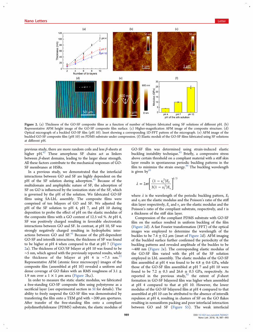
interactions between GO and SF are highly dependent on thepH of the SF solution during adsorption.42 Because of themultidomain and amphiphilic nature of SF, the adsorption ofSF on GO is influenced by the ionization state of the SF, whichis governed by the pH of the solution. We fabricated GO-SFfilms using SA-LbL assembly. The composite films werecomprised of ten bilayers of GO and SF. We adjusted thepH of the SF solution to pH 4, pH 7, and pH 10 duringdeposition to probe the effect of pH on the elastic modulus ofthe composite films with a GO content of 12.5 vol %. At pH 4,SF was positively charged resulting in favorable electrostaticinteractions between GO and SF. In contrast, at pH 10, SF wasstrongly negatively charged resulting in hydrophobic inter-actions between GO and SF.42 Because of the pH-dependentGO-SF and intersilk interactions, the thickness of SF was foundto be higher at pH 4 when compared to that at pH 7 (Figure2a). The thickness of GO/SF bilayer at pH 10 was found to be∼5 nm, which agreed with the previously reported results, whilethe thickness of the bilayer at pH 4 is ∼7.5 nm.22
Representative AFM (atomic force microscopy) images of thecomposite film (assembled at pH 10) revealed a uniform anddense coverage of GO flakes with an RMS roughness of 3.1 ±1.9 nm over a 1 × 1 μm area (Figure 2b,c).In order to measure the static elastic modulus, we fabricated
a free-standing GO-SF composite film using polystyrene as asacrificial layer (see experimental section in SI for details). Theability to freely suspend the GO-SF film was demonstrated bytransferring the film onto a TEM grid with ∼200 μm apertures.After transfer of the free-standing film onto a compliantpolydimethylsiloxane (PDMS) substrate, the elastic modulus of
GO-SF film was determined using strain-induced elasticbuckling instability technique.43 Briefly, a compressive stressabove certain threshold on a compliant material with a stiff skinlayer results in spontaneous periodic buckling patterns in thefilm to minimize the strain energy.44 The buckling wavelengthis given by45
λ πνν
=−−
⎡⎣⎢
⎤⎦⎥t
EE
2(1 )
3(1 )s2
f
f2
s
1/3
where λ is the wavelength of the periodic buckling pattern, Efand vf are the elastic modulus and the Poisson’s ratio of the stiffskin layer respectively, Es and vs are the elastic modulus and thePoisson’s ratio of the compliant substrate, respectively, and t isa thickness of the stiff skin layer.Compression of the compliant PDMS substrate with GO-SF
film on the surface resulted in uniform buckling of the film(Figure 2d). A fast Fourier transformation (FFT) of the opticalimages was employed to determine the wavelength of thebuckles to be 7.4 ± 0.2 μm (inset of Figure 2d). AFM imagingof the buckled surface further confirmed the periodicity of thebuckling patterns and revealed amplitude of the buckles to be∼400 nm (Figure 2e). The corresponding elastic modulus ofthe GO-SF film varied with the pH of the SF solutionemployed in LbL assembly. The elastic modulus of the GO-SFfilm assembled at pH 4 was found to be 4.8 ± 0.6 GPa, whilethose of the GO-SF film assembled at pH 7 and pH 10 werefound to be 7.2 ± 0.3 and 26.6 ± 0.3 GPa, respectively. Asreported in the previous study,42 the extent of β-sheetformation in GO-SF bilayered film was higher when assembledat pH 4 compared to that at pH 10. However, the lowermodulus of the GO-SF bilayered film at pH 4 compared to thatassembled at pH 10 can be attributed to the absence of intersilkrepulsion at pH 4, resulting in clusters of SF on the GO flakesresulting in nonuniform packing and poor interfacial interactionbetween GO and SF (Figure S5). The weak interfacial
Figure 2. (a) Thickness of the GO-SF composite films as a function of number of bilayers fabricated using SF solutions of different pH. (b)Representative AFM height image of the GO-SF composite film surface. (c) Higher-magnification AFM image of the composite structure. (d)Optical micrograph of a buckled GO-SF film (pH 10). Inset showing a corresponding 1D-FFT pattern of the micrograph. (e) AFM image of thebuckled GO-SF composite film (pH 10) on PDMS substrate under compression. (f) Elastic moduli of the GO-SF films fabricated using SF solutionsat different pH.
Nano Letters Letter
DOI: 10.1021/acs.nanolett.7b04421Nano Lett. 2018, 18, 987−993
989
interactions between the SF and GO leads to poor stresstransfer from SF matrix to GO and partial slippage of the GOflakes under compressive stress. Despite the lower β-sheetcontent in the GO-SF film assembled at pH 7 and pH 10, theSF chains uniformly distributed on the GO flakes and facilitatedbetter interfacial interactions and packing, thus enhancing theelastic modulus of the composite film (Figure S7). The vastmajority of fibrillar structures observed in at pH 7 and 10 wereindividual nanofibrils or limited multidomains, rather thanbundles as usually observed for longer adsorption onhydrophilic substrates.46 The absence of substantial aggregationand self-folding is critically important for maximizing interfacialinteractions among different SF domains and GO surface.47
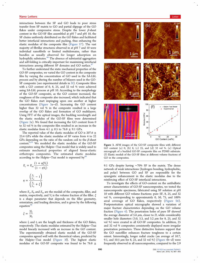
To further understand the static mechanical properties of theGO-SF composites, we varied the GO content in the compositefilm by varying the concentration of GO used in the SA-LbLprocess and by altering the number of bilayers used in the GO-SF composite (see experimental details in SI). Composite filmswith a GO content of 0, 8, 25, and 32 vol % were achievedusing SA-LbL process at pH 10. According to the morphologyof the GO-SF composite, as the GO content increased, theroughness of the composite also increased, which indicated thatthe GO flakes start impinging upon one another at higherconcentrations (Figure 3a−d). Increasing the GO contenthigher than 32 vol % in the composite resulted in a largeoverlap of the GO flakes and formation of GO multilayers.Using FFT of the optical images, the buckling wavelength andthe elastic modulus of the GO-SF films were determined(Figure 2e). We found that increasing the GO content from 0to 32 vol % in the composite film resulted in an increase in theelastic modulus from 4.1 ± 0.5 to 76.8 ± 9.1 GPa.The reported value of the elastic modulus of GO is 207.6 ±
23.4 GPa while the elastic modulus of SF varies from 4 to 22GPa depending on the ratio of the random coil to the β-sheetcontent.6,22 We modeled the elastic modulus of the GO-SFcomposites using the Halpin−Tsai model that is widely used toestimate mechanical properties of aligned linear-elasticorthotropic composites. The estimated elastic modulusaccording to the Halpin−Tsai model is expressed by48
ηξη
=+−
E EV
V(1 )(1 )c m
f
f
ηξ
=−
+
( )( )
1EE
EE
f
m
f
m
where Ec, Ef, and Em are the moduli of the composite, filler, andmatrix, respectively, and Vf is the volume fraction of the filler. ξis a shape parameter that depends on the filler geometry,orientation, and loading direction, and is given by the followingequation48
ξ =lt
23
f
f
where lf and tf are the length and thickness of the GO flakes,respectively. The elastic modulus estimated by the Halpin−Tsaimodel linearly increased with an increase in the GO content.The experimentally obtained elastic moduli of the GO-SFcomposites agreed well with the theoretical values, predicted bythe Halpin−Tsai model (Figure 3f). The highest elasticmodulus of the GO-SF composite was found to be 76.8 ±
9.1 GPa despite having ∼70% SF in the matrix. The densenetwork of weak interactions (hydrogen bonding, hydrophobic,and polar) between GO and SF are responsible for thesynergistic enhancement in the elastic modulus due to thereinforcing effect of GO-SF interfacial interactions.To investigate the effects of GO-content on the antiballistic
armor characteristics of GO-SF nanocomposites, we tested thenanocomposite specimens, fabricated using SF solution at pH10 with different GO volume fractions: pure SF, 8, 25, and 32vol %, corresponding to approximately 0, 50, 75, and 100%areal coverage of GO flakes, respectively (Figure S6).Postpenetration optical micrographs showed a variation ofmajor fracture characteristics depending on the GO volumefraction (Figure 4). The penetration holes of pure SF showedthe average diameter of 5.6 μm, closer to D, while considerablysmaller hole diameters (3.0, 3.3, and 3.2 μm for 8, 25, and 32vol %) were created in all GO-SF composites. In addition, 25and 32 vol % composites consistently displayed more irregularpenetration perimeters. These distinctive features support thatthe GO nanofiller enhances fracture toughness to a certainextent. Interestingly, longer radial cracks (an average of 10.7,9.1, and 10.5 μm for 8, 25, and 32 vol %) (Figure 4b−d) werefrequently observed in all nanocomposites, compared to the 2.9
Figure 3. AFM images of the GO-SF composite films with differentGO content (a) 0, (b) 8, (c) 25, and (d) 32 vol %. (e) Opticalmicrograph of a buckled GO-SF composite film on PDMS substrate.(f) Elastic moduli of the GO-SF films at different volume fractions ofGO in the composites.
Nano Letters Letter
DOI: 10.1021/acs.nanolett.7b04421Nano Lett. 2018, 18, 987−993
990
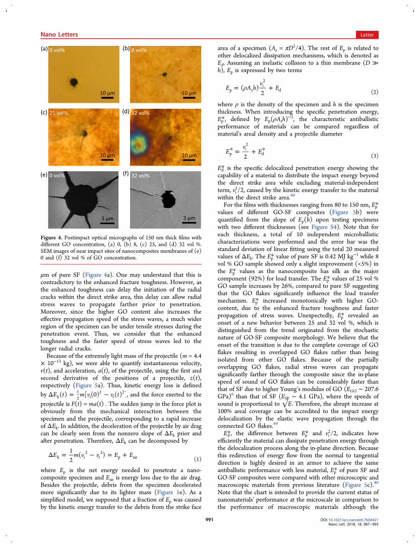
μm of pure SF (Figure 4a). One may understand that this iscontradictory to the enhanced fracture toughness. However, asthe enhanced toughness can delay the initiation of the radialcracks within the direct strike area, this delay can allow radialstress waves to propagate farther prior to penetration.Moreover, since the higher GO content also increases theeffective propagation speed of the stress waves, a much widerregion of the specimen can be under tensile stresses during thepenetration event. Thus, we consider that the enhancedtoughness and the faster speed of stress waves led to thelonger radial cracks.Because of the extremely light mass of the projectile (m = 4.4
× 10−13 kg), we were able to quantify instantaneous velocity,v(t), and acceleration, a(t), of the projectile, using the first andsecond derivative of the positions of a projectile, z(t),respectively (Figure 5a). Thus, kinetic energy loss is definedby Δ = −E t m v v t( ) [ (0) ( ) ]k
12 i
2r
2 , and the force exerted to the
projectile is F(t) = ma(t) . The sudden jump in the force plot isobviously from the mechanical interaction between thespecimen and the projectile, corresponding to a rapid increaseof ΔEk. In addition, the deceleration of the projectile by air dragcan be clearly seen from the nonzero slope of ΔEk prior andafter penetration. Therefore, ΔEk can be decomposed by
Δ = − = +E m v v E E12
( )k i2
r2
p air (1)
where Ep is the net energy needed to penetrate a nano-composite specimen and Eair is energy loss due to the air drag.Besides the projectile, debris from the specimen deceleratedmore significantly due to its lighter mass (Figure 1e). As asimplified model, we supposed that a fraction of Ep was causedby the kinetic energy transfer to the debris from the strike face
area of a specimen (As = πD2/4). The rest of Ep is related toother delocalized dissipation mechanisms, which is denoted asEd. Assuming an inelastic collision to a thin membrane (D ≫h), Ep is expressed by two terms
ρ= +E A hv
E( )2p si2
d (2)
where ρ is the density of the specimen and h is the specimenthickness. When introducing the specific penetration energy,Ep*, defined by Ep(ρAsh)
−1, the characteristic antiballisticperformance of materials can be compared regardless ofmaterial’s areal density and a projectile diameter
* = + *Ev
E2i
p
2
d (3)
Ed* is the specific delocalized penetration energy showing thecapability of a material to distribute the impact energy beyondthe direct strike area while excluding material-independentterm, vi
2/2, caused by the kinetic energy transfer to the materialwithin the direct strike area.40
For the films with thicknesses ranging from 80 to 150 nm, Ep*values of different GO-SF composites (Figure 5b) werequantified from the slope of Ep(h) upon testing specimenswith two different thicknesses (see Figure S4). Note that foreach thickness, a total of 10 independent microballisticcharacterizations were performed and the error bar was thestandard deviation of linear fitting using the total 20 measuredvalues of ΔEk. The Ep* value of pure SF is 0.42 MJ kg−1 while 8vol % GO sample showed only a slight improvement (<5%) inthe Ep* values as the nanocomposite has silk as the majorcomponent (92%) for load transfer. The Ep* values of 25 vol %GO sample increases by 26%, compared to pure SF suggestingthat the GO flakes significantly influence the load transfermechanism. Ep* increased monotonically with higher GO-content, due to the enhanced fracture toughness and fasterpropagation of stress waves. Unexpectedly, Ep* revealed anonset of a new behavior between 25 and 32 vol %, which isdistinguished from the trend originated from the stochasticnature of GO-SF composite morphology. We believe that theonset of the transition is due to the complete coverage of GOflakes resulting in overlapped GO flakes rather than beingisolated from other GO flakes. Because of the partiallyoverlapping GO flakes, radial stress waves can propagatesignificantly farther through the composite since the in-planespeed of sound of GO flakes can be considerably faster thanthat of SF due to higher Young’s modulus of GO (EGO ∼ 207.6GPa)6 than that of SF (ESF ∼ 4.1 GPa), where the speeds ofsound is proportional to √E. Therefore, the abrupt increase at100% areal coverage can be accredited to the impact energydelocalization by the elastic wave propagation through theconnected GO flakes.49
Ed*, the difference between Ep* and vi2/2, indicates how
efficiently the material can dissipate penetration energy throughthe delocalization process along the in-plane direction. Becausethis redirection of energy flow from the normal to tangentialdirection is highly desired in an armor to achieve the sameantiballistic performance with less material, Ep* of pure SF andGO-SF composites were compared with other microscopic andmacroscopic materials from previous literature (Figure 5c).40
Note that the chart is intended to provide the current status ofnanomaterials’ performance at the microscale in comparison tothe performance of macroscopic materials although the
Figure 4. Postimpact optical micrographs of 150 nm thick films withdifferent GO concentration, (a) 0, (b) 8, (c) 25, and (d) 32 vol %.SEM images of near impact sites of nanocomposites membranes of (e)0 and (f) 32 vol % of GO concentration.
Nano Letters Letter
DOI: 10.1021/acs.nanolett.7b04421Nano Lett. 2018, 18, 987−993
991
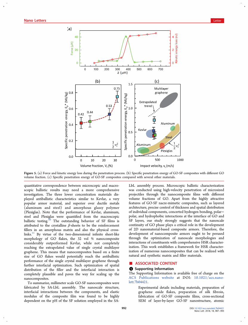
quantitative correspondence between microscopic and macro-scopic ballistic results may need a more comprehensiveinvestigation. The three lower concentration materials dis-played antiballistic characteristics similar to Kevlar, a verypopular armor material, and superior over ductile metals(aluminum and steel) and amorphous glassy polymer(Plexiglas). Note that the performance of Kevlar, aluminum,steel and Plexiglas were quantified from the macroscopicballistic testing.50 The outstanding behavior of SF films isattributed to the crystalline β-sheets to be the reinforcementfillers in an amorphous matrix and also the physical cross-links.11 By virtue of the two-dimensional infinite sheet-likemorphology of GO flakes, the 32 vol % nanocompositeconsiderably outperformed Kevlar, while not completelyreaching the extrapolated value of single crystal multilayergraphene. This means that nanocomposites based on a finitesize of GO flakes would potentially reach the antiballisticperformance of the single crystal multilayer graphene throughfurther interfacial optimization. Such optimization of spatialdistribution of the filler and the interfacial interaction iscompletely plausible and paves the way for scaling up thenanocomposites.To summarize, millimeter scale GO-SF nanocomposites were
fabricated by SA-LbL assembly. The nanoscale structure,interfacial interactions between the components, and elasticmodulus of the composite film was found to be highlydependent on the pH of the SF solution employed in the SA-
LbL assembly process. Microscopic ballistic characterizationwas conducted using high-velocity penetration of microsizedprojectiles through the nanocomposite films with differentvolume fractions of GO. Apart from the highly attractivefeatures of GO-SF nacre-mimetic composites, such as layeredarchitecture, precise control of thickness and spatial distributionof individual components, concerted hydrogen bonding, polar−polar, and hydrophobic interactions at the interface of GO andSF layers, our study strongly suggests that the nanoscalecontinuity of GO phase plays a critical role in the developmentof 2D nanomaterial-based composite armors. Therefore, thedevelopment of nanocomposite armors ought to be perusedthrough the optimization of nanoscale morphologies andinteractions of constituents with comprehensive HSR character-ization. This work establishes a framework for HSR character-ization of numerous nanocomposites that can be realized withnatural and synthetic matrix and filler materials.
■ ASSOCIATED CONTENT*S Supporting InformationThe Supporting Information is available free of charge on theACS Publications website at DOI: 10.1021/acs.nano-lett.7b04421.
Experimental details including materials, preparation ofgraphene oxide flakes, preparation of silk fibroin,fabrication of GO-SF composite films, cross-sectionalSEM of layer-by-layer GO-SF nanostructure, atomic
Figure 5. (a) Force and kinetic energy loss during the penetration process. (b) Specific penetration energy of GO-SF composites with different GOvolume fraction. (c) Specific penetration energy of GO-SF composites compared with several other materials.
Nano Letters Letter
DOI: 10.1021/acs.nanolett.7b04421Nano Lett. 2018, 18, 987−993
992
force microscopy, buckling test, microballistic testing,specific penetration energy, additional figures, table, andreferences (PDF)
■ AUTHOR INFORMATIONCorresponding Authors*E-mail: (J.-H.L.) [email protected].*E-mail: (S.S.) [email protected] Xie: 0000-0002-0151-6362Srikanth Singamaneni: 0000-0002-7203-2613Jae-Hwang Lee: 0000-0002-2546-1044Author ContributionsThe authors W. X. and S. T. contributed equally to this work.The manuscript was written through contributions of allauthors. All authors have given approval to the final version ofthe manuscript.Author ContributionsThe authors W.X. and S.T. contributed equally to this work.The authors would like thank Nanoresearch Facility andInstitute of Materials Science and Engineering at WashingtonUniversity for providing access to central microscopy facilities.FundingThis research was supported by the U.S. Army ResearchLaboratory under contract W911NF-15-2-0024 and Air ForceOffice of Scientific Research under award # FA9550-15-1-0228.NotesThe authors declare no competing financial interest.
■ REFERENCES(1) Sinha Ray, S.; Okamoto, M. Prog. Polym. Sci. 2003, 28 (11),1539−1641.(2) Podsiadlo, P.; Kaushik, A. K.; Arruda, E. M.; Waas, A. M.; Shim,B. S.; Xu, J. D.; Nandivada, H.; Pumplin, B. G.; Lahann, J.;Ramamoorthy, A.; Kotov, N. A. Science 2007, 318 (5847), 80−83.(3) Kim, H.; Abdala, A. A.; Macosko, C. W. Macromolecules 2010, 43(16), 6515−6530.(4) National Research Council. Opportunities in protection materialsscience and technology for future Army applications; National AcademiesPress, 2011; pp 24−34.(5) Kumar, N.; Kumbhat, S. Essenstials in Nanoscience andNanotechnology; John Wiley & Sons, Inc: Hoboken, New Jersey,2016; pp 273−277.(6) Suk, J. W.; Piner, R. D.; An, J.; Ruoff, R. S. ACS Nano 2010, 4(11), 6557−6564.(7) Compton, O. C.; Nguyen, S. T. Small 2010, 6 (6), 711−723.(8) Eda, G.; Fanchini, G.; Chhowalla, M. Nat. Nanotechnol. 2008, 3(5), 270−274.(9) Porter, D.; Vollrath, F. Adv. Mater. 2009, 21 (4), 487−492.(10) Jin, H.-J.; Kaplan, D. L. Nature 2003, 424 (6952), 1057−1061.(11) Jiang, C.; Wang, X.; Gunawidjaja, R.; Lin, Y. H.; Gupta, M. K.;Kaplan, D. L.; Naik, R. R.; Tsukruk, V. V. Adv. Funct. Mater. 2007, 17(13), 2229−2237.(12) Chen, F.; Porter, D.; Vollrath, F. Acta Biomater. 2012, 8 (7),2620−2627.(13) Hu, K.; Kulkarni, D. D.; Choi, I.; Tsukruk, V. V. Prog. Polym. Sci.2014, 39 (11), 1934−1972.(14) Kharlampieva, E.; Kozlovskaya, V.; Chan, J.; Ankner, J. F.;Tsukruk, V. V. Langmuir 2009, 25 (24), 14017−14024.(15) Jiang, C.; Markutsya, S.; Tsukruk, V. V. Adv. Mater. 2004, 16(2), 157−161.(16) Vozar, S.; Poh, Y.-C.; Serbowicz, T.; Bachner, M.; Podsiadlo, P.;Qin, M.; Verploegen, E.; Kotov, N.; Hart, A. J. Rev. Sci. Instrum. 2009,80 (2), 023903.
(17) Richardson, J. J.; Bjornmalm, M.; Caruso, F. Science 2015, 348(6233), aaa2491.(18) Chen, H.; Muller, M. B.; Gilmore, K. J.; Wallace, G. G.; Li, D.Adv. Mater. 2008, 20 (18), 3557−3561.(19) Xu, Y.; Hong, W.; Bai, H.; Li, C.; Shi, G. Carbon 2009, 47 (15),3538−3543.(20) An, Z.; Compton, O. C.; Putz, K. W.; Brinson, L. C.; Nguyen, S.T. Adv. Mater. 2011, 23 (33), 3842−3846.(21) Kharlampieva, E.; Kozlovskaya, V.; Wallet, B.; Shevchenko, V.V.; Naik, R. R.; Vaia, R.; Kaplan, D. L.; Tsukruk, V. V. ACS Nano2010, 4 (12), 7053−7063.(22) Hu, K.; Gupta, M. K.; Kulkarni, D. D.; Tsukruk, V. V. Adv.Mater. 2013, 25 (16), 2301−2307.(23) Kulkarni, D. D.; Choi, I.; Singamaneni, S. S.; Tsukruk, V. V. ACSNano 2010, 4 (8), 4667−4676.(24) Yin, Y.; Hu, K.; Grant, A. M.; Zhang, Y.; Tsukruk, V. V.Langmuir 2015, 31 (39), 10859−10870.(25) Wang, Y.; Ma, R.; Hu, K.; Kim, S.; Fang, G.; Shao, Z.; Tsukruk,V. V. ACS Appl. Mater. Interfaces 2016, 8 (37), 24962−24973.(26) Tang, Z.; Kotov, N. a; Magonov, S.; Ozturk, B. Nat. Mater.2003, 2 (6), 413−418.(27) Podsiadlo, P.; Liu, Z.; Paterson, D.; Messersmith, P. B.; Kotov,N. A. Adv. Mater. 2007, 19 (7), 949−955.(28) Li, X.; Chang, W. C.; Chao, Y. J.; Wang, R.; Chang, M. NanoLett. 2004, 4 (4), 613−617.(29) Li, X.; Xu, Z. H.; Wang, R. Nano Lett. 2006, 6 (10), 2301−2304.(30) Burghard, Z.; Zini, L.; Srot, V.; Bellina, P.; van Aken, P. A.; Bill,J. Nano Lett. 2009, 9, 4103−4108.(31) Xu, Z. H.; Li, X. Adv. Funct. Mater. 2011, 21 (20), 3883−3888.(32) Xia, W.; Ruiz, L.; Pugno, N. M.; Keten, S. Nanoscale 2016, 8(12), 6456−6462.(33) Xia, W.; Song, J.; Meng, Z.; Shao, C.; Keten, S. Mol. Syst. Des.Eng. 2016, 1 (1), 40−47.(34) El-Magd, E. J. Phys. IV 1994, 4 (C8), C8-149−C8-170.(35) Radford, D. D.; Walley, S. M.; Church, P.; Field, J. E. J. Phys. IV2003, 110, 263−268.(36) Al-Mousawi, M. M.; Reid, S. R.; Deans, W. F. Proc. Inst. Mech.Eng., Part C 1997, 211 (4), 273−292.(37) Sarva, S.; Mulliken, A. D.; Boyce, M. C. Int. J. Solids Struct. 2007,44 (7−8), 2381−2400.(38) Watson, S.; Gifford, M.; Field, J. E. J. Appl. Phys. 2000, 88 (1),65−69.(39) Lee, J.-H.; Veysset, D.; Singer, J. P.; Retsch, M.; Saini, G.;Pezeril, T.; Nelson, K. A.; Thomas, E. L. Nat. Commun. 2012, 3 (May),1164.(40) Lee, J.-H.; Loya, P. E.; Lou, J.; Thomas, E. L. Science 2014, 346(6213), 1092−1096.(41) Thevamaran, R.; Lawal, O.; Yazdi, S.; Jeon, S.-J. J.; Lee, J.-H.;Thomas, E. L. Science 2016, 354 (6310), 312−316.(42) Tadepalli, S.; Hamper, H.; Park, S. H.; Cao, S.; Naik, R. R.;Singamaneni, S. ACS Biomater. Sci. Eng. 2016, 2, 1084.(43) Stafford, C. M.; Harrison, C.; Beers, K. L.; Karim, A.; Amis, E. J.;VanLandingham, M. R.; Kim, H.-C.; Volksen, W.; Miller, R. D.;Simonyi, E. E. Nat. Mater. 2004, 3 (8), 545−550.(44) Genzer, J.; Groenewold, J. Soft Matter 2006, 2 (4), 310.(45) Singamaneni, S.; Tsukruk, V. V. Soft Matter 2010, 6 (22), 5681.(46) Shulha, H.; Po Foo, C. W.; Kaplan, D. L.; Tsukruk, V. V.Polymer 2006, 47 (16), 5821−5830.(47) Cho, J.; Char, K.; Hong, J.-D.; Lee, K.-B. Adv. Mater. 2001, 13(14), 1076−1078.(48) Affdl, J. C.; Kardos, J. L. Polym. Eng. Sci. 1976, 16, 344−352.(49) Sadeghzadeh, S. Appl. Phys. A: Mater. Sci. Process. 2016, 122 (7),655.(50) Lee, B. L.; Walsh, T. F.; Won, S. T.; Patts, H. M.; Song, J. W.;Mayer, A. H. J. Compos. Mater. 2001, 35 (18), 1605−1633.
Nano Letters Letter
DOI: 10.1021/acs.nanolett.7b04421Nano Lett. 2018, 18, 987−993
993


![Graphene-Oxide Functionalized with 2-Ureido-4[1H]- pyrimidinone … · 2020. 10. 21. · 1 Graphene-Oxide Functionalized with 2-Ureido-4[1H]-pyrimidinone for Production of Nacre-Like](https://img.pdfslide.us/doc/110x75/61126fc5c8ab861af070f35f/graphene-oxide-functionalized-with-2-ureido-41h-pyrimidinone-2020-10-21.jpg)