Embed Size (px)
Citation preview
1
Extraction of boron nitride nanotubes and fabrication
of macroscopic articles using chlorosulfonic acid
Mohammed Adnan,1,† Daniel M. Marincel,1 Olga Kleinerman,2 Sang-Hyon Chu,3 Cheol Park,4
Samuel Hocker,4 Catharine Fay,4 Sivaram Arepalli,1 Yeshayahu Talmon,2 and Matteo
Pasquali1,‡
1Department of Chemical and Biomolecular Engineering and Department of Chemistry, The
Smalley-Curl Institute, Rice University, Houston, TX 77005, USA.
2Department of Chemical Engineering, Technion-Israel Institute of Technology and the Russell
Berrie Nanotechnology Institute (RBNI), Haifa 3200003, Israel.
3National Institute of Aerospace, 100 Exploration Way, Hampton, VA 23666, USA.
4NASA Langley Research Center, Hampton, VA 23681, USA
Nanotechnology; Boron nitride nanotubes; Chlorosulfonic acid; Nanotube extraction; Thin films;
Foams
Due to recent advances in high-throughput synthesis, research on boron nitride nanotubes
(BNNTs) is moving towards applications. One future goal is the assembly of macroscopic articles
of high aspect ratio, pristine BNNTs. However, these articles are presently unattainable because
of insufficient purification and fabrication methods. We introduce a solution process for extracting

2
BNNTs from synthesis impurities without sonication or the use of surfactants and proceed to
convert the extracted BNNTs into thin films. The solution process can also be used to convert as-
synthesized material—which contains significant amounts of hexagonal boron nitride (h-BN)—
into mats and foams with controllable structure and dimension. The scalable solution extraction
method, combined with further advances in synthesis and purification, contributes to the
development of all-BNNT macroscopic articles, such as fibers and 3-D structures.

3
Boron nitride nanotubes (BNNTs) are structural analogues of carbon nanotubes (CNTs) with
comparable Young’s modulus (1.3 TPa), tensile strength (~40 GPa),1 and thermal conductivity
(300-3000 W/mK).2 BNNTs are chemically different from CNTs; they are wide bandgap
semiconductors regardless of chirality3 and are stable up to 900°C in air.4 In addition, BNNTs are
piezoelectric5 and photoluminescent in the ultraviolet range.6 Due to these unique properties,
BNNTs are being targeted for use in applications such as oxidation resistant heat shields,7, 8
chemically inert catalyst supports, high-temperature dielectrics for electrical wires, and chemical
resistant coatings for metals.9
The development of gram-scale synthesis in the laboratory setting has prepared BNNTs to be
useful in a variety of applications. Starting with the first synthesis in 1995,10 BNNTs have
primarily been synthesized using low-throughput synthesis techniques, permitting selectivity for
high concentrations of crystalline BNNTs with few byproducts but at the expense of a low
production rate.11 The past decade has seen the development of several routes to produce gram-
scale quantities of BNNTs, including the high temperature-pressure (HTP) method12 and the radio
frequency induction plasma based synthesis with and without hydrogen.13, 14 All the high
production methods rely on high-temperature condensation and growth that results in higher
material production rates with significant synthesis byproducts, including boron nitride
polymorphs like hexagonal boron nitride (h-BN).
Several purification routes have been developed15-26 to provide sufficient material for lab-scale
studies. The current purification approaches include polymer wrapping,15-17 non-covalent
functionalization,18-21 DNA and peptide mediated isolation,22-25 and dispersion in aqueous solution
via ionic surfactants.26 In addition to the use of surfactants, these methods often rely on sonication,
which has been shown to result in damage to the BNNTs.27 Another attractive purification route
4
is simple chemical purification using acids and solvents; however, this is difficult due to the
chemical similarity between the h-BN impurities and BNNTs. These approaches are difficult to
scale up to provide sufficient material for macroscopic articles and composites of pristine BNNTs.
Here, we demonstrate purification and assembly of BNNTs into macroscale articles via solution
processing with chlorosulfonic acid (CSA) as a solvent. A recent study indicated that CSA acts as
a true solvent for BNNTs.28 In the current study, the preferential solubility of BNNTs compared
to h-BN and other byproducts is used to extract BNNTs without surfactants or sonication.
Furthermore, we show the formation of sub-micron BNNT layer films, millimeter thick mats, and
centimeter scale BNNT foams through the use of CSA.
All the BNNTs used in this report were synthesized by the high temperature high pressure process
and supplied by NASA.12 Our initial analysis by high-resolution scanning electron microscopy
(HR-SEM), x-ray photoelectron spectroscopy (XPS), and x-ray diffraction (XRD) (presented in
the supporting information) indicated that the starting material contains elemental boron, h-BN,
and boron oxide (B2O3) in addition to BNNTs.
Infrared spectroscopy (ATR IR), x-ray photoelectron spectroscopy (XPS), and thermogravimetric
analysis (TGA) were used to determine any possible reactions of CSA with BNNTs (details in
supplementary information). As-synthesized BNNTs were mixed with CSA (Sigma Aldrich) at
0.7 wt% to form a gray slurry. The slurry was then filtered through a 25 mm diameter, 20 nm pore-
size alumina filter (Whatman Anodisc 25), and formed a wet disc. Chloroform (Sigma Aldrich)
was added to precipitate the BNNT solids and remove CSA, followed by washing with ethyl
alcohol (Fisher Scientific) and water to remove chloroform, sulfuric acid, hydrochloric acid, and
other CSA-chloroform reaction byproducts prior to drying in vacuum at 35 °C for 48 hours. The
5
ATR IR data from the CSA-treated BNNT material showed some broadening and a small shift of
the B-N peaks with no new spectral features. Although XPS indicated that residual sulfur and
chlorine are present in the CSA-treated BNNT material, this is due to residual acid. The absence
of new spectral features attributable to BNNT functionalization indicates that no permanent
chemical reactions between BNNTs and CSA occurred, in agreement with previous electron
energy loss spectroscopy.28 In addition to permitting analysis of the BNNT-CSA interactions, this
process also illustrates one route to form structurally stable BNNT mats.
The extraction of BNNTs was performed by centrifugation. BNNTs were mixed with CSA at 100
ppm (by mass) in a speed-mixer (FlackTek DAC600.1FVZ) at 3250 rpm for 1 hour to form a
beige-colored BNNT-CSA slurry. The BNNT-CSA slurry was centrifuged in a Sorvall Legend X1
at 3500 x g and separated into two phases with a clear, golden-colored solution supernatant, similar
to h-BN dispersed in CSA.29, 30 The clear supernatant was separated using a Pasteur pipette, then
filtered to form sub-micron thin films.
Sub-micron thin films were prepared by filtering the supernatant using a 20 nm pore size alumina
filter paper and transferred onto substrates (borosilicate glass slides and perfluoroalkoxy alkane
(PFA) films) by floating the film in water.31, 32 Thin films with thickness ~10 nm (maximum height
in cross-section SEM) were deposited on a glass microscope slide (Figure 1A inset).
Characterization by HR-SEM was carried out after 24 hours of air drying (Figure 1A).
Thicker films (~500 nm as estimated by cross-section SEM) were prepared by filtering
supernatants from two batches of extracted material (150 mg BNNTs dissolved in 10 mL CSA
each). The thicker films were transferred to PFA substrates (McMaster-Carr) and later peeled off
with tweezers (Figure 1B inset), indicating that BNNTs do not physisorb to PFA. Unlike the thin

6
films, the thicker films were self-supporting; to our knowledge, this is the first demonstration of a
self-standing sub-micron macroscopic artifact composed of BNNTs in the absence of a polymer
matrix or binders.
2
Figure 1. A. HR-SEM of a thin film of BNNTs from the supernatant after centrifugation. B. HR-
SEM of the self-supporting film. Insets show the macroscopic appearance of the material imaged
by HR-SEM.
Figure 1A shows a HR-SEM (Zeiss Ultra Plus SEM; 0.7-2 kV acceleration voltage, 2.9-3.3 mm
separation distance) image of the thin film coated on a glass substrate. A low accelerating voltage
of 1.00 kV was used to minimize charging on the insulating sample with no metal coating. An
increase in the ratio of nanotubes to non-nanotube structures was observed compared to images of
the as-synthesized material (see supporting information), and indicated that the preferential
dissolution of nanotubes in CSA may be used to purify the as-synthesized material. Figure 1B is
a HR-SEM image of the freestanding thicker film showing an interconnected network of BNNT
bundles with few non-nanotube structures. This interconnected structure provides the necessary
mechanical support for the thin film to resist fracture under its own weight.
Backscattered SEM images (see supplementary information) do not indicate a significant variation
in density between the BNNTs and non-nanotube structures that remain in the supernatant. Since

7
Smith et al. reported that the BNNTs formed by the HTP process has a B:N ratio of 1,12 it is
probable that the non-nanotube structures observed are impurities such as h-BN, boron, or B2O3.
These non-nanotube structures are likely present in the supernatant because they are chemically
bonded to BNNTs, permitting them to remain suspended in CSA post-centrifugation. Chemical
bonding between BNNTs and the impurities is expected since the current proposed model for
BNNT growth in the HTP synthesis begins with the condensation of boron droplets, which then
react with atomic nitrogen in high pressure to form BNNTs on the droplet surfaces.12 This
synthesis mechanism explains why star-shaped structures can be seen in the supernatant, with non-
nanotube impurities holding fibrils together at a common hub (Figure 1A).
The remaining material from the extraction process was gradually quenched in excess water, solids
filtered, then dried in an oven (Lindberg / Blue M Gravity Oven) at 150 °C for 48 hours. Analysis
on the precipitate (supporting information) indicated the presence of elemental boron, h-BN, and
B2O3 with a small percentage of BNNTs. This indicates that although the extraction process does
not remove all BNNTs, it will sufficiently remove all individualized BNNTs. It is expected that
the BNNTs not dissolved in CSA are bonded to non-nanotubes.
Since as-synthesized BNNTs form stable dispersions in CSA, methods used for solution
processing CNTs33-37 may also be applied to BNNTs. As a demonstration, a 2000 ppm mass
concentration of BNNT in CSA slurry was poured into 1 cm3 steel mesh cages (McMaster-Carr)
wrapped with Teflon tape (McMaster-Carr) and coagulated in cold ether (Fisher Scientific). The
gels shrank to ~0.5 cm3 upon coagulation (Figure 2). This process resembles the injection molding
of CNTs as demonstrated by Hsu et al.38 Similar processes may be used to prepare high-surface-
area BNNT foams for a variety of applications.

8
Figure 2. BNNT foam (0.5 cm3) foam fabricated by coagulating a BNNT/CSA solution in cold
diethyl ether.
In conclusion, solubility-driven separation was used to extract BNNTs from byproducts in CSA.
ATR IR showed that CSA does not chemically functionalize or react with BNNTs at room
temperature and pressure. The preferential solubility of BNNTs in CSA permits scaled solution
processing to extract BNNTs. The solution can be filtered and collected on various surfaces to
form thermally conductive, chemically resistant thin films that can protect a substrate from
extreme heat and corrosion. In addition, the suspension of as-produced BNNT material in CSA
provides the first route for molding BNNT foams into any desired shape. The mats and films
produced herein may be used for low-density thermal protection articles capable of withstanding
high temperatures in an oxidizing environment.
ASSOCIATED CONTENT
The following files are available free of charge.

9
Spectroscopy of precipitates. Backscattered SEM, XPS, XRD, ATR IR, TGA, and DSC on the
processed material (PDF).
AUTHOR INFORMATION
Corresponding Author
‡Matteo Pasquali ([email protected])
Department of Chemical and Biomolecular Engineering and Department of Chemistry
Rice University
6100 Main Street, MS 369
Houston, TX 77005, USA
Present Addresses
†Dr. Mohammed Adnan now with Abu Dhabi Financial Group, Abu Dhabi, UAE.
Author Contributions
The manuscript was written through contributions of all authors. All authors have given approval
to the final version of the manuscript.
Funding Sources
Funding was provided by NASA grant NNX15AK72G, the Robert A. Welch Foundation grant C-
1668, the United States-Israel Binational Science Foundation, and AFOSR FA9550-15-1-0370.
DMM was partially supported by a Wiess Teacher-Scholar Fellowship; MA was partially support
by a Ph.D. scholarship from Abu Dhabi National Oil Company (ADNOC).
Notes

10
HR-SEM imaging was performed at the Laboratory for Electron Microscopy of Soft Matter,
supported by the Technion Russell Berrie Nanotechnology Institute (RBNI).
ACKNOWLEDGMENT
The authors acknowledge Dr. Amanda L. Tiano for helping with ATR spectroscopy at NASA
LaRC, Virginia, USA.
ABBREVIATIONS
BNNT, boron nitride nanotube; h-BN, hexagonal boron nitride; CNT, carbon nanotubes; HTP,
high temperature-pressure; CSA, chlorosulfonic acid; B2O3, boron oxide; ATR IR, attenuated total
reflectance infrared spectroscopy; PFA, perfluoroalkoxy alkane; HR-SEM, high resolution
scanning electron microscopy; XPS, x-ray photoelectron spectroscopy; XRD, x-ray diffraction
REFERENCES
1. Arenal, R.; Wang, M. S.; Xu, Z.; Loiseau, A.; Golberg, D. Nanotechnology 2011, 22, (26), 6.
2. Chang, C. W.; Fennimore, A. M.; Afanasiev, A.; Okawa, D.; Ikuno, T.; Garcia, H.; Li, D. Y.;
Majumdar, A.; Zettl, A. Physical Review Letters 2006, 97, (8), 4.
3. Golberg, D.; Bando, Y.; Huang, Y.; Terao, T.; Mitome, M.; Tang, C. C.; Zhi, C. Y. ACS Nano
2010, 4, (6), 2979-2993.
4. Chen, Y.; Zou, J.; Campbell, S. J.; Le Caer, G. Applied Physics Letters 2004, 84, (13), 2430-
2432.
5. Nakhmanson, S. M.; Calzolari, A.; Meunier, V.; Bernholc, J.; Nardelli, M. B. Physical Review
B 2003, 67, (23), 5.
6. Gao, R.; Yin, L. W.; Wang, C. X.; Qi, Y. X.; Lun, N.; Zhang, L. Y.; Liu, Y. X.; Kang, L.;
Wang, X. F. Journal of Physical Chemistry C 2009, 113, (34), 15160-15165.
7. Daniel, A.; Badhe, Y.; Srikanth, I.; Gokhale, S.; Balasubramanian, K. Industrial &
Engineering Chemistry Research 2016, 55, (40), 10645-10655.
8. Tiano, A. L.; Park, C.; Lee, J. W.; Luong, H. H.; Gibbons, L. J.; Chu, S.-H.; Applin, S.; Gnoffo,
P.; Lowther, S.; Kim, H. J.; Danehy, P. M.; Inman, J. A.; Jones, S. B.; Kang, J. H.; Sauti,
G.; Thibeault, S. A.; Yamakov, V.; Wise, K. E.; Su, J.; Fay, C. C. Proc. SPIE 2014, 9060,
906006-906006-19.
9. Pakdel, A.; Zhi, C. Y.; Bando, Y.; Golberg, D. Materials Today 2012, 15, (6), 256-265.
10. Chopra, N. G.; Luyken, R. J.; Cherrey, K.; Crespi, V. H.; Cohen, M. L.; Louie, S. G.; Zettl, A.
Science 1995, 269, (5226), 966-967.
11. Lee, C. H.; Bhandari, S.; Tiwari, B.; Yapici, N.; Zhang, D. Y.; Yap, Y. K. Molecules 2016, 21,
(7), 19.

11
12. Smith, M. W.; Jordan, K. C.; Park, C.; Kim, J. W.; Lillehei, P. T.; Crooks, R.; Harrison, J. S.
Nanotechnology 2009, 20, (50), 6.
13. Kim, K. S.; Kingston, C. T.; Hrdina, A.; Jakubinek, M. B.; Guan, J. W.; Plunkett, M.; Simard,
B. ACS Nano 2014, 8, (6), 6211-6220.
14. Fathalizadeh, A.; Pham, T.; Mickelson, W.; Zettl, A. Nano Letters 2014, 14, (8), 4881-4886.
15. Zhi, C. Y.; Bando, Y.; Tang, C. C.; Xie, R. G.; Sekiguchi, T.; Golberg, D. Journal of the
American Chemical Society 2005, 127, (46), 15996-15997.
16. Choi, J. H.; Kim, J.; Seo, D.; Seo, Y. S. Materials Research Bulletin 2013, 48, (3), 1197-1203.
17. Zhi, C. Y.; Bando, Y.; Tang, C. C.; Honda, S.; Sato, K.; Kuwahara, H.; Golberg, D.
Angewandte Chemie-International Edition 2005, 44, (48), 7929-7932.
18. Xie, S. Y.; Wang, W.; Fernando, K. A. S.; Wang, X.; Lin, Y.; Sun, Y. P. Chemical
Communications 2005, (29), 3670-3672.
19. Kim, D.; Sawada, T.; Zhi, C. Y.; Bando, Y.; Golberg, D.; Serizawa, T. Journal of Nanoscience
and Nanotechnology 2014, 14, (4), 3028-3033.
20. Wang, W. L.; Bando, Y.; Zhi, C. Y.; Fu, W. Y.; Wang, E. G.; Golberg, D. Journal of the
American Chemical Society 2008, 130, (26), 8144.
21. Velayudham, S.; Lee, C. H.; Xie, M.; Blair, D.; Bauman, N.; Yap, Y. K.; Green, S. A.; Liu, H.
Y. ACS Applied Materials & Interfaces 2010, 2, (1), 104-110.
22. Zhi, C.; Bando, Y.; Wang, W.; Tang, C.; Kuwahara, H.; Golberg, D. Chemistry-an Asian
Journal 2007, 2, (12), 1581-1585.
23. Gao, Z. H.; Zhi, C. Y.; Bando, Y.; Golberg, D.; Serizawa, T. Journal of the American Chemical
Society 2010, 132, (14), 4976.
24. Ansari, R.; Ajori, S.; Ameri, A. Applied Surface Science 2016, 366, 233-244.
25. Lee, C. H.; Zhang, D. Y.; Yap, Y. K. Journal of Physical Chemistry C 2012, 116, (2), 1798-
1804.
26. Yu, J.; Chen, Y.; Cheng, B. M. Solid State Communications 2009, 149, (19-20), 763-766.
27. Liao, Y.; Chen, Z.; Connell, J. W.; Fay, C. C.; Park, C.; Kim, J.-W.; Lin, Y. Advanced
Functional Materials 2014, 24, (28), 4497-4506.
28. Kleinerman, O.; Mohammed, A.; Marincel, D. M.; Ma, A. W. K.; Bengio, A.; Park, C.; Chu,
S.-H.; Pasquali, M.; Talmon, Y. Unpublished Experiments.
29. Jasuja, K. Designing nanoscale constructs from atomic thin sheets of graphene, boron nitride
and gold nanoparticles for advanced material applications. Kansas State University, 2011.
30. Morishita, T.; Okamoto, H. ACS Applied Materials & Interfaces 2016, 8, (40), 27064-27073.
31. Hecht, D. S.; Heintz, A. M.; Lee, R.; Hu, L. B.; Moore, B.; Cucksey, C.; Risser, S.
Nanotechnology 2011, 22, (7), 5.
32. Wu, Z. C.; Chen, Z. H.; Du, X.; Logan, J. M.; Sippel, J.; Nikolou, M.; Kamaras, K.; Reynolds,
J. R.; Tanner, D. B.; Hebard, A. F.; Rinzler, A. G. Science 2004, 305, (5688), 1273-1276.
33. Vitale, F.; Summerson, S. R.; Aazhang, B.; Kemere, C.; Pasquali, M. ACS Nano 2015, 9, (4),
4465-4474.
34. Mirri, F.; Ma, A. W. K.; Hsu, T. T.; Behabtu, N.; Eichmann, S. L.; Young, C. C.; Tsentalovich,
D. E.; Pasquali, M. ACS Nano 2012, 6, (11), 9737-9744.
35. Pasquali, M.; Whiting, T. Y. T. H.; Mirri, F.; Whiting, B. T., Fabrication of carbon foams
through solution processing in superacids. US 20140141224, 2014.
36. Behabtu, N.; Lomeda, J. R.; Green, M. J.; Higginbotham, A. L.; Sinitskii, A.; Kosynkin, D.
V.; Tsentalovich, D.; Parra-Vasquez, A. N. G.; Schmidt, J.; Kesselman, E.; Cohen, Y.;
Talmon, Y.; Tour, J. M.; Pasquali, M. Nature Nanotechnology 2010, 5, (6), 406-411.

12
37. Bengio, E. A.; Tsentalovich, D. E.; Behabtu, N.; Kleinerman, O.; Kesselman, E.; Schmidt, J.;
Talmon, Y.; Pasquali, M. ACS Applied Materials & Interfaces 2014, 6, (9), 6139-6146.
38. Hsu, T. T.; Whiting, B. T.; Mirri, F.; Williams, S. M.; Yu, M.; Ganguli, S.; Amama, P. B.;
Zhao, W.; Rajukumar, L. P.; Cheng, G.; Walker, A. R. H.; Terrones, M.; Suhr, J.;
Maruyama, B.; Roy, A. K.; Pasquali, M. Unpublished Experiments.

13
Extraction of boron nitride nanotubes and
fabrication of macroscopic articles using
chlorosulfonic acid
Supporting Information: Spectroscopy of Precipitates
1 HR-SEM of As-synthesized Material High resolution SEM of the BNNTs as-synthesized and after CSA extraction are shown in Figure
S3. A higher percentage of the objects observed are fibrils after extraction compared to before.
Star-shaped structures can be seen in the extracted material, indicating that impurities attached to
BNNTs are not fully removed.
Figure S3: HR-SEM of BNNTs (a) before and (b) after CSA extraction. Note that the small
particles are silicon dioxide contaminants from cutting the glass slide after the BNNTs were
collected.

14
2 X-Ray Photoelectron Spectroscopy (XPS) 2.1 Survey Scans XPS survey scans show approximate elemental compositions of the as-synthesized material and
the precipitates using a pass energy of 26 eV (Figure S4). The as-synthesized BNNTs have boron,
nitrogen, oxygen, and carbon at concentrations of 48.8 at.%, 48.1 at.%, 2.4 at.%, and 0.7 at.%,
respectively. Adventitious oxygen and carbon are likely contaminants on the sample surface and
in the XPS stage. After exposure to CSA followed by direct quenching in chloroform and washing
in isopropanol and water (i.e. no centrifugation), the material consisted of approximately 35 at.%
of boron and nitrogen in a 1:1 ratio. However, approximately 21 at.% oxygen along with 10 at.%
adventitious carbon was detectable. The remaining 2 at.% was composed of sulfuric acid.
Figure S4. Survey scans of as-synthesized BNNTs and precipitates between 100 – 1100 eV
showing presence of sulfur, boron, carbon, nitrogen, and oxygen before (top, gray) and after
(bottom, red) exposure to CSA.
2.2 Deconvolution on As-Synthesized Material Deconvolution of the scans indicates the presence of elemental boron, and BxNyOz species as the
chief impurities present in as-synthesized BNNTs (Figure S5). Presence of elemental boron, BN
and BxNyOz, and B2O3 species were observed at binding energies of 187.7 eV, 190.6 eV, 192.8
eV, and 193.4 eV, respectively, for B1s signals. N1s signals also confirm the presence of BN at
398.3 eV, BxNyOz species at 400.3 eV, along with presence of possible contamination at 395.4 eV.
XPS peaks obtained due to oxygen and carbon were too noisy to be delineated.
1003506008501100
Inte
nsi
ty (
a.u
.)
Binding Energy (eV)
Precipitate Raw
-S
2p-
B1s
-C
1s
-N
1s
-O
1s
-O
KL
L
B1s: 48.8 %
N1s: 48.1 %
O1s: 2.4%
C1s: 0.7 %
B1s: 35.0 %
N1s: 32.3 %
O1s: 20.6%
C1s: 10.1 %
S2p: 2.0 %

15
[1] BN Position: 190.62 eV Height: 0.3 FWHM: 2.0 eV [2] BxNyOz Position: 192.82 eV Height: 0.2 FWHM: 1.6 eV [3] B2O3 Position: 193.4 eV Height: 0.2 FWHM: 1.3 eV [4] BNxO(1-x)
Position: 189.5 eV Height: 0.2 FWHM: 1.5 eV [5] B Position: 187.3 eV Height: 2E-5 FWHM: 0.5 eV
2: 0.262
[1] BN Position: 398.3 eV Height: 0.5 FWHM: 2.5 eV [2] BxNyOz Position: 400.3 eV Height: 0.3 FWHM: 2.1 eV [3] CxHyNz (contamination) Pos: 395.4 eV Height: 0.2 FWHM: 1.4 eV
2: 0.048
Figure S5. Deconvolution of B1s and N1s spectra of as-synthesized BNNTs showing the presence
of elemental boron, BxNxOy species, and BN species.
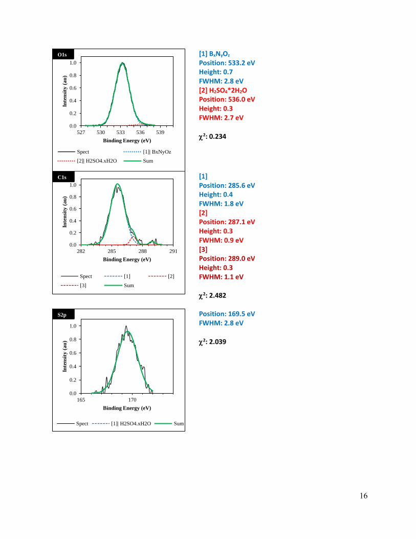
2.3 Deconvolution on CSA Processed BNNTs Deconvolutions of the oxygen, carbon, sulfur, boron, and nitrogen peaks for the pellet after
centrifugation and quenching with water are shown by Figure S6. Full deconvolution fit data is
provided in the figure.
0.0
0.2
0.4
0.6
0.8
1.0
186 188 190 192 194
Inte
nsi
ty (
au
)
Binding Energy (eV)
Spect [1] BN
[2]| BxNyOz [3]| B2O3
[4]| BNxO(1-x) [5]| B
B1s
395 397 399 401 403
Inte
nsi
ty (
au
)
Binding Energy (eV)
Spect [1]| BN[2]| -NH species [3]| CxHyNzSum
N1s
16
[1] BxNyOz Position: 533.2 eV Height: 0.7 FWHM: 2.8 eV [2] H2SO4*2H2O Position: 536.0 eV Height: 0.3 FWHM: 2.7 eV
2: 0.234
[1] Position: 285.6 eV Height: 0.4 FWHM: 1.8 eV [2] Position: 287.1 eV Height: 0.3 FWHM: 0.9 eV [3] Position: 289.0 eV Height: 0.3 FWHM: 1.1 eV
2: 2.482
Position: 169.5 eV FWHM: 2.8 eV
2: 2.039
0.0
0.2
0.4
0.6
0.8
1.0
527 530 533 536 539
Inte
nsi
ty (
au
)
Binding Energy (eV)
Spect [1]| BxNyOz
[2]| H2SO4.xH2O Sum
O1s
0.0
0.2
0.4
0.6
0.8
1.0
282 285 288 291
Inte
nsi
ty (
au
)
Binding Energy (eV)
Spect [1] [2]
[3] Sum
C1s
0.0
0.2
0.4
0.6
0.8
1.0
165 170
Inte
nsi
ty (
au
)
Binding Energy (eV)
Spect [1]| H2SO4.xH2O Sum
S2p

17
Figure S6. XPS on BNNT precipitates showing B1s, N1s, O1s, S1s, and C1s binding energies.
[1] B Position: 187.7 eV Height: 0.03 FWHM: 1.8 eV [2] BN Position: 190.7 eV Height: 0.6 FWHM: 1.3 eV [3] BxNyOz Position: 191.6 eV Height: 0.1 FWHM: 1.2 eV [4] B2O3 Position: 194.0 eV Height: 0.2 FWHM: 2.2 eV
2: 0.269
[1] BN Position: 398.2 eV Height 0.5 eV FWHM: 1.6 eV [2] BxNyOz
Position: 402.2 eV Height: 0.2 FWHM: 1.8 eV [3] N-H Position: 399.3 eV Height: 0.3 FWHM: 1.4 eV
2: 0.206
185 190 195
Inte
nsi
ty (
au
)
Binding Energy (eV)
Spect [1]| B[2]| BN [3]| BxNyOz[4]| B2O3 Sum
B1s
396 398 400 402 404
Inte
nsi
ty (
au
)
Binding Energy (eV)
Spect [1]| BN[2]| BxNyOz [3]| N-HSum
N1s

18
Data on the XPS deconvolutions for as-synthesized BNNTs and after quenching from CSA is
shown in Table S1 to assist in comparison for the reader.
Table S1: Peak-fit deconvolution of XPS peaks for as-produced BNNT and CSA treated BNNT
solids.
B(1s) BNNT
CSA treated
BNNT N(1s) BNNT
CSA treated
BNNT O(1s) BNNT
CSA treated
BNNT C(1s) BNNT
CSA treated
BNNT S(2p) BNNT
CSA treated
BNNT
BN BN [1] [1]
Position 190.6 190.7 398.3 398.2 - - - 285.6 - 169.5
Height 0.3 0.6 0.5 0.5 - - - 0.4 - -
FWHM 2 1.3 2.5 1.6 - - - 1.8 - 2.8
BxNyOz BxNyOz BxNyOz [2]
Position 192.82 191.6 400.3 402.2 - 533.2 - 287.1 - -
Height 0.2 0.1 0.3 0.2 - 0.7 - 0.3 - -
FWHM 1.6 1.2 2.1 1.8 - 2.8 - 0.9 - -
B2O3 CxHyNz (contamination) H2SO4*2H2O [3]
Position 193.4 194 395.4 - - 536 - 289 - -
Height 0.2 0.2 0.2 - - 0.3 - 0.3 - -
FWHM 1.3 2.2 1.4 - - 2.7 - 1.1 - -
BNxO(1-
x) N-H
Position 189.5 - - 399.3 - - - - - -
Height 0.2 - - 0.3 - - - - - -
FWHM 1.5 - - 1.4 - - - - - -
[5] B
Position 187.3 187.7 - - - - - - - -
Height 2E-05 0.03 - - - - - - - -
FWHM 0.5 1.8 - - - - - - - -
χ2 0.262 0.269 0.048 0.206 0.234 2.482 2.039
19
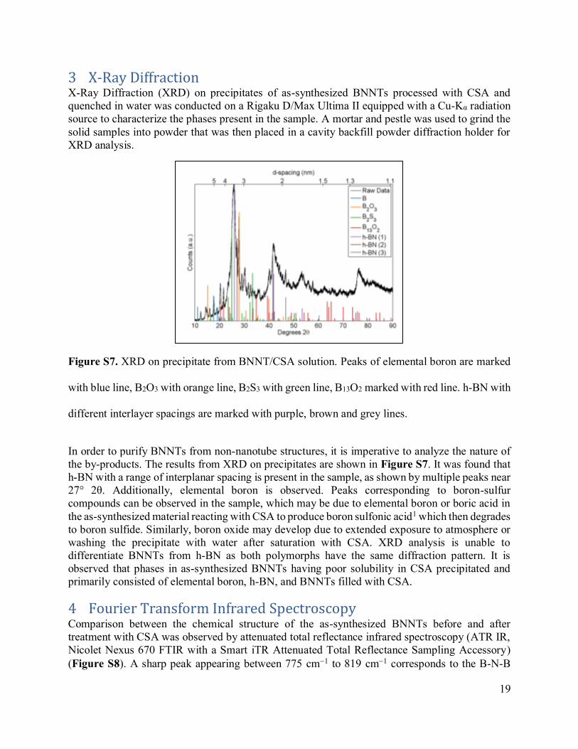
3 X-Ray Diffraction X-Ray Diffraction (XRD) on precipitates of as-synthesized BNNTs processed with CSA and
quenched in water was conducted on a Rigaku D/Max Ultima II equipped with a Cu-Kα radiation
source to characterize the phases present in the sample. A mortar and pestle was used to grind the
solid samples into powder that was then placed in a cavity backfill powder diffraction holder for
XRD analysis.
Figure S7. XRD on precipitate from BNNT/CSA solution. Peaks of elemental boron are marked
with blue line, B2O3 with orange line, B2S3 with green line, B13O2 marked with red line. h-BN with
different interlayer spacings are marked with purple, brown and grey lines.
In order to purify BNNTs from non-nanotube structures, it is imperative to analyze the nature of
the by-products. The results from XRD on precipitates are shown in Figure S7. It was found that
h-BN with a range of interplanar spacing is present in the sample, as shown by multiple peaks near
27° 2θ. Additionally, elemental boron is observed. Peaks corresponding to boron-sulfur
compounds can be observed in the sample, which may be due to elemental boron or boric acid in
the as-synthesized material reacting with CSA to produce boron sulfonic acid1 which then degrades
to boron sulfide. Similarly, boron oxide may develop due to extended exposure to atmosphere or
washing the precipitate with water after saturation with CSA. XRD analysis is unable to
differentiate BNNTs from h-BN as both polymorphs have the same diffraction pattern. It is
observed that phases in as-synthesized BNNTs having poor solubility in CSA precipitated and
primarily consisted of elemental boron, h-BN, and BNNTs filled with CSA.
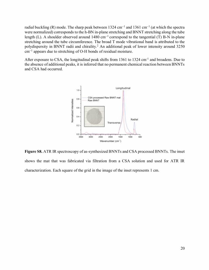
4 Fourier Transform Infrared Spectroscopy Comparison between the chemical structure of the as-synthesized BNNTs before and after
treatment with CSA was observed by attenuated total reflectance infrared spectroscopy (ATR IR,
Nicolet Nexus 670 FTIR with a Smart iTR Attenuated Total Reflectance Sampling Accessory)
(Figure S8). A sharp peak appearing between 775 cm-1 to 819 cm-1 corresponds to the B-N-B
20
radial buckling (R) mode. The sharp peak between 1324 cm-1 and 1361 cm-1 (at which the spectra
were normalized) corresponds to the h-BN in-plane stretching and BNNT stretching along the tube
length (L). A shoulder observed around 1480 cm-1 correspond to the tangential (T) B-N in-plane
stretching around the tube circumference. The broad T mode vibrational band is attributed to the
polydispersity in BNNT radii and chirality.2 An additional peak of lower intensity around 3250
cm-1 appears due to stretching of O-H bonds of residual moisture.
After exposure to CSA, the longitudinal peak shifts from 1361 to 1324 cm-1 and broadens. Due to
the absence of additional peaks, it is inferred that no permanent chemical reaction between BNNTs
and CSA had occurred.
Figure S8. ATR IR spectroscopy of as-synthesized BNNTs and CSA processed BNNTs. The inset
shows the mat that was fabricated via filtration from a CSA solution and used for ATR IR
characterization. Each square of the grid in the image of the inset represents 1 cm.
21
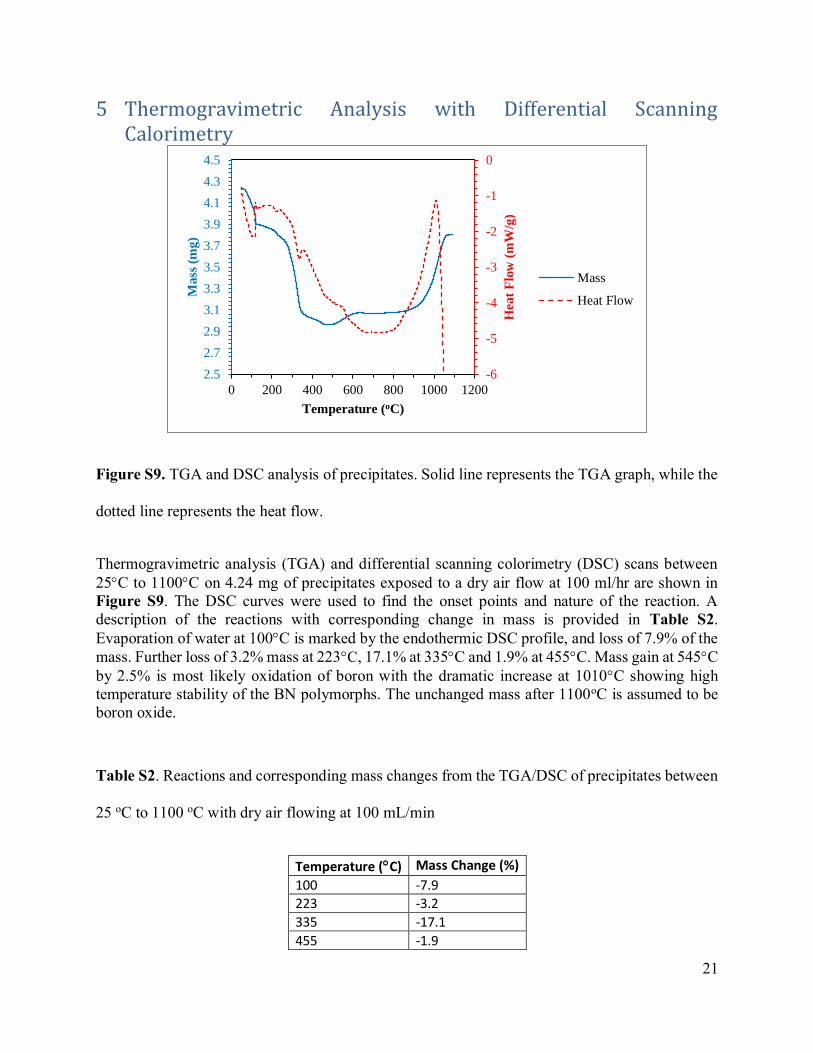
5 Thermogravimetric Analysis with Differential Scanning Calorimetry
Figure S9. TGA and DSC analysis of precipitates. Solid line represents the TGA graph, while the
dotted line represents the heat flow.
Thermogravimetric analysis (TGA) and differential scanning colorimetry (DSC) scans between
25C to 1100C on 4.24 mg of precipitates exposed to a dry air flow at 100 ml/hr are shown in
Figure S9. The DSC curves were used to find the onset points and nature of the reaction. A
description of the reactions with corresponding change in mass is provided in Table S2.
Evaporation of water at 100C is marked by the endothermic DSC profile, and loss of 7.9% of the
mass. Further loss of 3.2% mass at 223C, 17.1% at 335C and 1.9% at 455C. Mass gain at 545C
by 2.5% is most likely oxidation of boron with the dramatic increase at 1010C showing high
temperature stability of the BN polymorphs. The unchanged mass after 1100oC is assumed to be
boron oxide.
Table S2. Reactions and corresponding mass changes from the TGA/DSC of precipitates between
25 oC to 1100 oC with dry air flowing at 100 mL/min
Temperature (C) Mass Change (%)
100 -7.9
223 -3.2
335 -17.1
455 -1.9
-6
-5
-4
-3
-2
-1
0
2.5
2.7
2.9
3.1
3.3
3.5
3.7
3.9
4.1
4.3
4.5
0 200 400 600 800 1000 1200
Heat
Flo
w (
mW
/g)
Mass
(m
g)
Temperature (oC)
Mass
Heat Flow

22
545 +2.5 1010 +17.3
6 Backscattered SEM Images Backscattered SEM image of the thin film fabricated from the supernatant is shown in Figure S10.
Particles with higher density or higher Z (marked with arrows) tend to appear brighter than the
BNNT fibrils. These particles are likely silicon oxide that originate from cutting the glass slide
after collecting the BNNTs. Other non-BNNT material shows a similar contrast in backscatter to
BNNTs.
Figure S10. (a) Secondary and (b) backscattered images of the thin film deposited on the glass
slide. Arrows show particles that are brighter in backscatter than BNNTs, implying a higher
electron density, likely silicon oxide from the glass slide.
7 Bibliography 1. Kiasat, A. R.; Fallah-Mehrjardi, M., B(HSO4)3: a novel and efficient solid acid catalyst for
the regioselective conversion of epoxides to thiocyanohydrins under solvent-free
conditions. Journal of the Brazilian Chemical Society 2008, 19, 1595-1599.
2. Wirtz, L.; Rubio, A.; de la Concha, R. A.; Loiseau, A., Ab initio calculations of the lattice
dynamics of boron nitride nanotubes. Physical Review B 2003, 68 (4), 13.
![Boron Nitride Nanotubes for Biomedical Applications ...€¦ · between two graphite electrodes [7], the search for new nanotubes has increased in order to find materials that one](https://img.pdfslide.us/doc/110x75/5fcd0414d0d0682e1746ade8/boron-nitride-nanotubes-for-biomedical-applications-between-two-graphite-electrodes.jpg)