Embed Size (px)
Citation preview
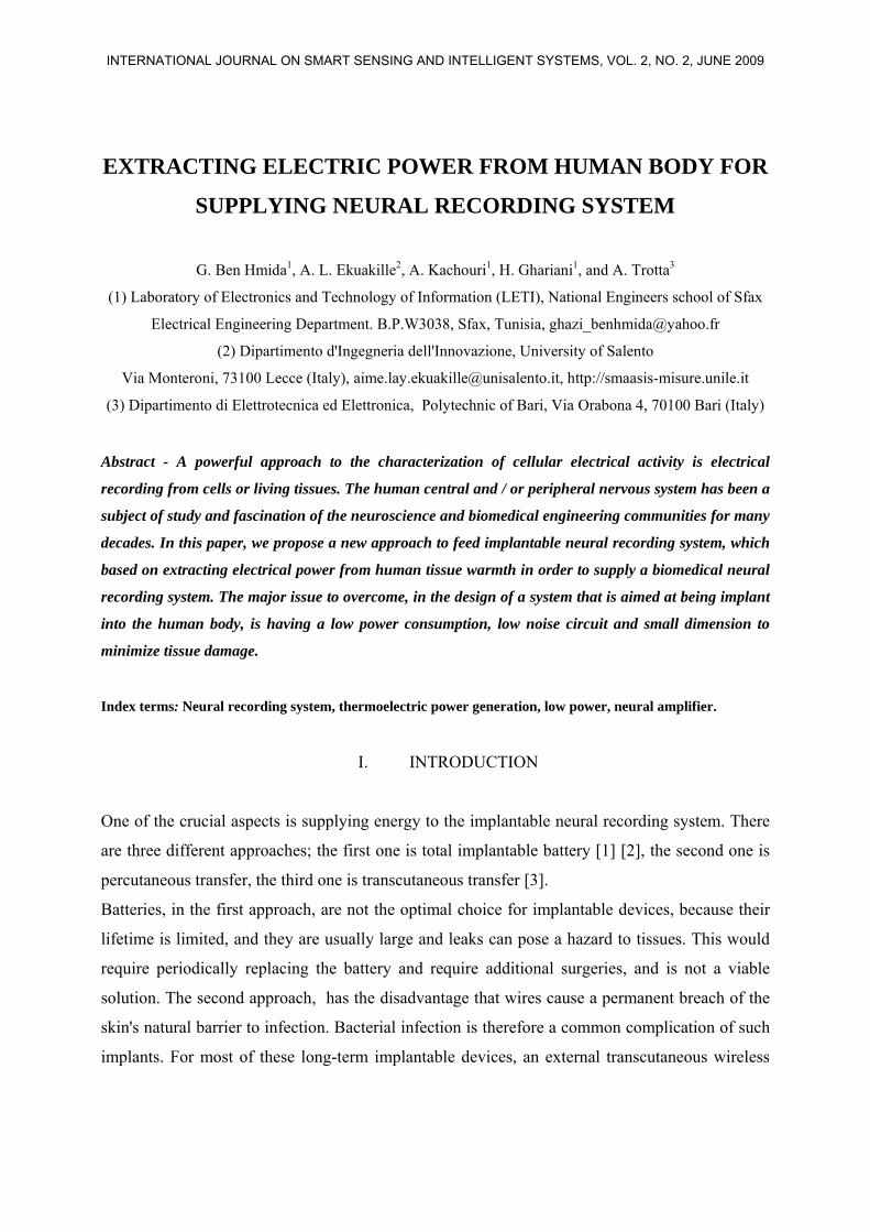
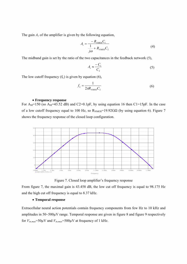
EXTRACTING ELECTRIC POWER FROM HUMAN BODY FOR
SUPPLYING NEURAL RECORDING SYSTEM
G. Ben Hmida1, A. L. Ekuakille2, A. Kachouri1, H. Ghariani1, and A. Trotta3
(1) Laboratory of Electronics and Technology of Information (LETI), National Engineers school of Sfax
Electrical Engineering Department. B.P.W3038, Sfax, Tunisia, [email protected]
(2) Dipartimento d'Ingegneria dell'Innovazione, University of Salento
Via Monteroni, 73100 Lecce (Italy), [email protected], http://smaasis-misure.unile.it
(3) Dipartimento di Elettrotecnica ed Elettronica, Polytechnic of Bari, Via Orabona 4, 70100 Bari (Italy)
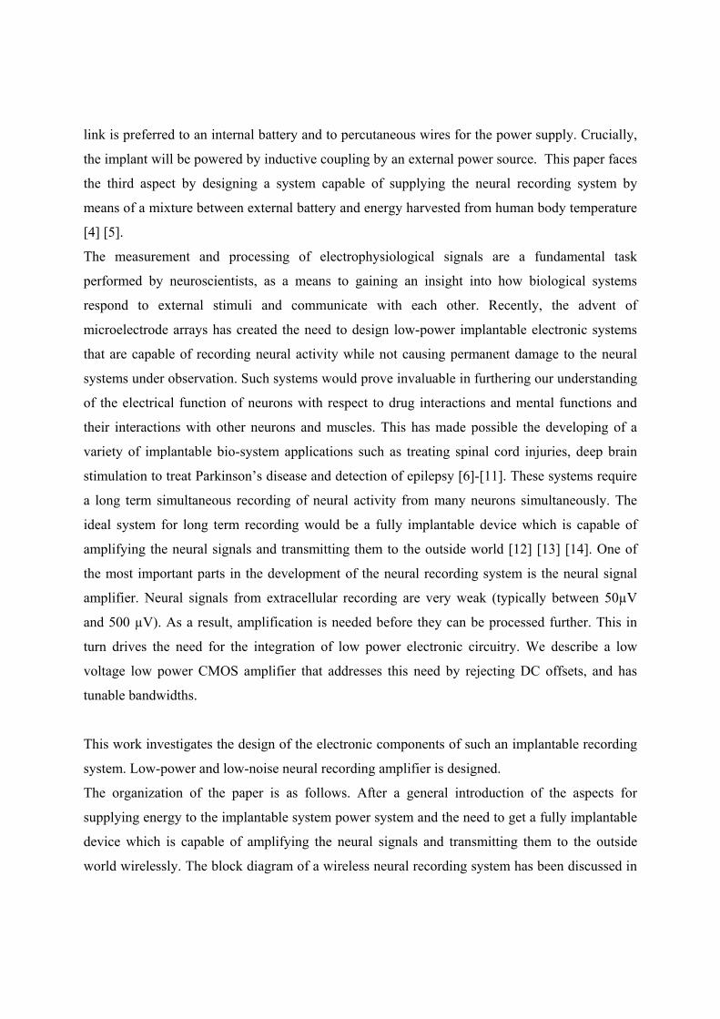
Abstract - A powerful approach to the characterization of cellular electrical activity is electrical
recording from cells or living tissues. The human central and / or peripheral nervous system has been a
subject of study and fascination of the neuroscience and biomedical engineering communities for many
decades. In this paper, we propose a new approach to feed implantable neural recording system, which
based on extracting electrical power from human tissue warmth in order to supply a biomedical neural
recording system. The major issue to overcome, in the design of a system that is aimed at being implant
into the human body, is having a low power consumption, low noise circuit and small dimension to
minimize tissue damage.
Index terms: Neural recording system, thermoelectric power generation, low power, neural amplifier.
I. INTRODUCTION
One of the crucial aspects is supplying energy to the implantable neural recording system. There
are three different approaches; the first one is total implantable battery [1] [2], the second one is
percutaneous transfer, the third one is transcutaneous transfer [3].
Batteries, in the first approach, are not the optimal choice for implantable devices, because their
lifetime is limited, and they are usually large and leaks can pose a hazard to tissues. This would
require periodically replacing the battery and require additional surgeries, and is not a viable
solution. The second approach, has the disadvantage that wires cause a permanent breach of the
skin's natural barrier to infection. Bacterial infection is therefore a common complication of such
implants. For most of these long-term implantable devices, an external transcutaneous wireless
INTERNATIONAL JOURNAL ON SMART SENSING AND INTELLIGENT SYSTEMS, VOL. 2, NO. 2, JUNE 2009

section II. Energy harvesting from human body temperature has been presented in section III. In
section IV, the characteristics of neural recording amplifier have been presented. The simulation
results, of the neural amplifier with adjustable gain and low cutoff frequency, have been
discussed in section V. The paper has been concluded in section VI.
II. OVERVIEW OF THE WIRELESS NEURAL RECORDING SYSTEM
The block diagram of the neural recording system is shown in Figure 1. The extracellular
electrical activities of single or multiple neurons, in proximity of small recording sites on a
micro-electrode array, create neural signals in the range of 50~500 μV. Low-power and low-
noise amplifiers with built-in bandpass filtering capability amplify the neural signals in the
desired frequency range [15] [16]. The amplified signal will be processed and transmitted to
external unit wirelessly through a miniaturized antenna. The implantable part is supplied by
power and data via an inductive link [17]. It consists of two coils, forming a loosely coupled
transformer. The primary coil, placed outside the body, generates a magnetic field which is partly
picked up by the secondary coil that is implanted. In this way, power and data can be transferred
wirelessly, overcoming the skin barrier. The implanted device is externally controlled and
powered by a modulated radio frequency (RF) signal. The inductive antenna (receiver coil) picks
up the transmitted RF carrier, followed by a rectifier, an AC/DC-voltage converter and regulator,
an ASK demodulator for recovering transmitted data and a clock recovery. The clock is generated
by rectifying the received RF signal and dividing it down. Generating the clock, in this way,
ensures that it does not drift with respect to the external transmitter and control circuitry. The
external receiver unit picks up the neural signal, digitizes it, and transfers it to the PC for further
signal processing, storing and visualization.
The external control unit is responsible of the mode selection and generation of command words
to the implant. It contains a control data encoder, an ASK (Amplitude Shift Keying) modulator
and a class E power amplifier. The new approach discussed in this paper consists of the use of
two batteries. Battery 1 is a commercial one, while the battery 2 is used to stocks the power from
the thermoelectric power generation Sensor array ‘MPG-D602’.
INTERNATIONAL JOURNAL ON SMART SENSING AND INTELLIGENT SYSTEMS, VOL. 2, NO. 2, JUNE 2009

well this waste heat can be recovered. Assuming normal body temperature and a relatively low
room temperature (20° C), the Carnot efficiency is
(310 293 ) 5.5%310
body ambient
body
T T K KT K− −
= =
(1)
In a hot environment (27°C) the Carnot efficiency falls to
(310 300 ) 3.2%310
body ambient
body
T T K KT K− −
= =
(2)
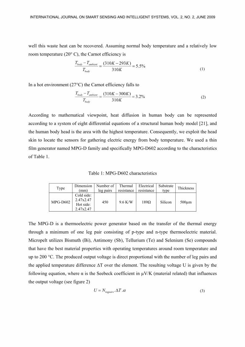
According to mathematical viewpoint, heat diffusion in human body can be represented
according to a system of eight differential equations of a structural human body model [21], and
the human body head is the area with the highest temperature. Consequently, we exploit the head
skin to locate the sensors for gathering electric energy from body temperature. We used a thin
film generator named MPG-D family and specifically MPG-D602 according to the characteristics
of Table 1.
Table 1: MPG-D602 characteristics
Type Dimension (mm)
Number of leg pairs
Thermal resistance
Electrical resistance
Substrate type Thickness
MPG-D602
Cold side: 2.47x2.47 Hot side: 2.47x2.47
450 9.6 K/W 189Ω Silicon 500µm
The MPG-D is a thermoelectric power generator based on the transfer of the thermal energy
through a minimum of one leg pair consisting of p-type and n-type thermoelectric material.
Micropelt utilizes Bismuth (Bi), Antimony (Sb), Tellurium (Te) and Selenium (Se) compounds
that have the best material properties with operating temperatures around room temperature and
up to 200 °C. The produced output voltage is direct proportional with the number of leg pairs and
the applied temperature difference ∆T over the element. The resulting voltage U is given by the
following equation, where α is the Seebeck coefficient in µV/K (material related) that influences
the output voltage (see figure 2)
. .legpairsU N T α= Δ (3)
INTERNATIONAL JOURNAL ON SMART SENSING AND INTELLIGENT SYSTEMS, VOL. 2, NO. 2, JUNE 2009
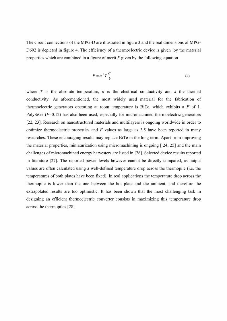

Figure 2. MPG output in function of Seebeck coefficient
Figure 3. Circuit connections
Figure 4. MPG-D601 real dimensions
INTERNATIONAL JOURNAL ON SMART SENSING AND INTELLIGENT SYSTEMS, VOL. 2, NO. 2, JUNE 2009
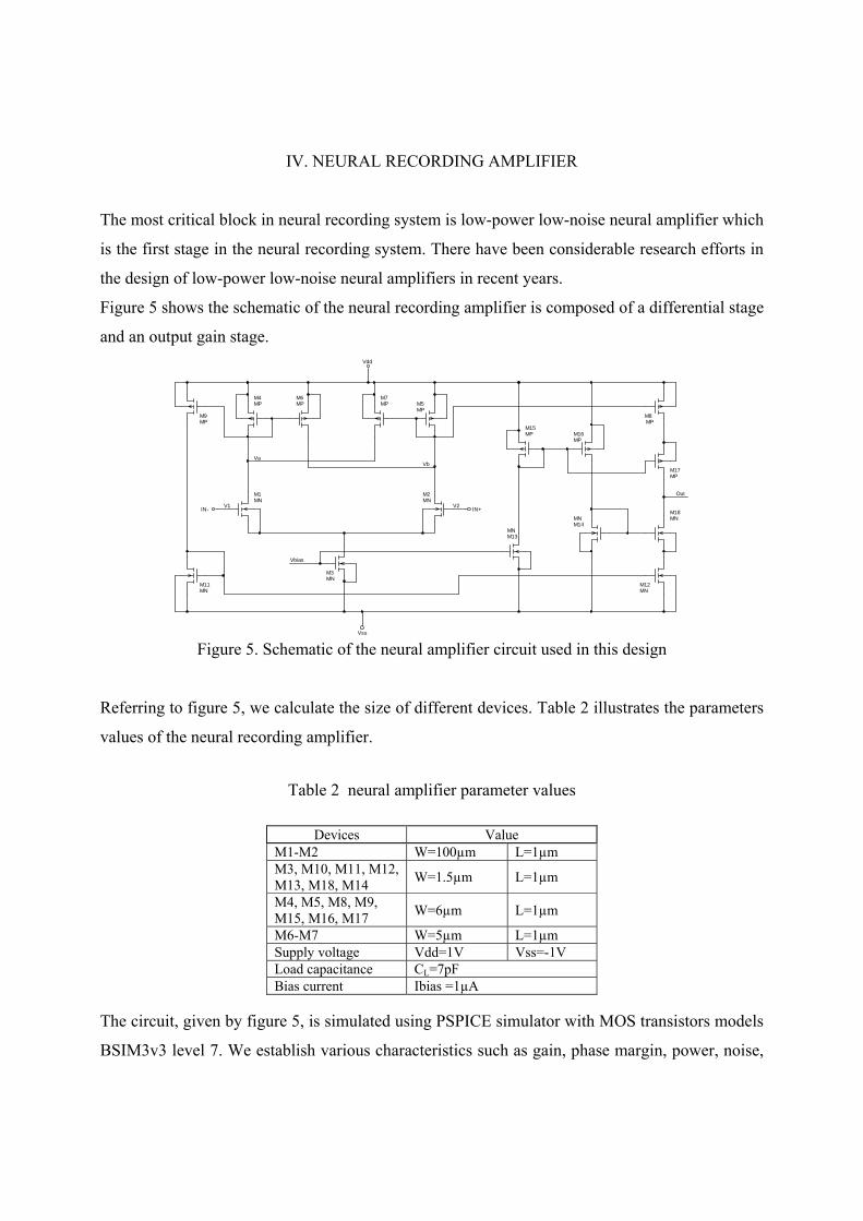
CMRR, PSRR, and offset. Table 3 summarizes the simulation results of the open loop neural
recording amplifier.
Table 3. Simulated Performance Characteristics of neural amplifier
Parameters Value Gain GdB = 43.95 dB
Phase margin Mφ = 64.6° Gain-BandWidth GBW = 1.1294 MHz
Power Consumption Ptot= 9.22 µW Total Current
absorbed Itot=4.617 µA
CMRR=113.27dB Common Mode Rejection Ratio CMRR > 92dB @ f <
10KHz PSRRVss=73.11dB Power Supply
Rejection Ratio PSRRVdd=75.29dB CMR+=806mV Output-voltage swing CMR-=992mV
DC Offset 196µV Input Referred Noise Vni,rms = 14.8 µVrms
Noise Efficiency Factor NEF=13,22
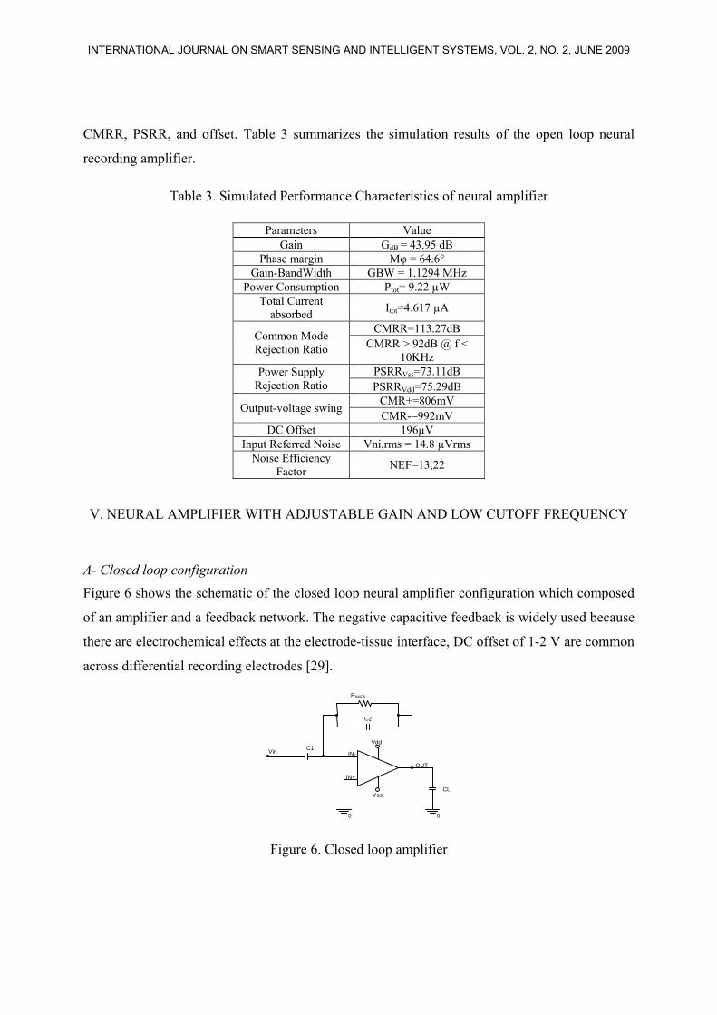
V. NEURAL AMPLIFIER WITH ADJUSTABLE GAIN AND LOW CUTOFF FREQUENCY
A- Closed loop configuration Figure 6 shows the schematic of the closed loop neural amplifier configuration which composed
of an amplifier and a feedback network. The negative capacitive feedback is widely used because
there are electrochemical effects at the electrode-tissue interface, DC offset of 1-2 V are common
across differential recording electrodes [29].
Figure 6. Closed loop amplifier
Vdd
C2
IN+
OUT
IN-
RNMOS
CL
C1 Vin
Vss
0 0
INTERNATIONAL JOURNAL ON SMART SENSING AND INTELLIGENT SYSTEMS, VOL. 2, NO. 2, JUNE 2009
Time
90ms 91ms 92ms 93ms 94ms 95ms 96ms 97ms 98ms 99ms 100msV(V1:+)
-50uV
0V
50uV
SEL>>
V(Out)-10mV
0V
10mV
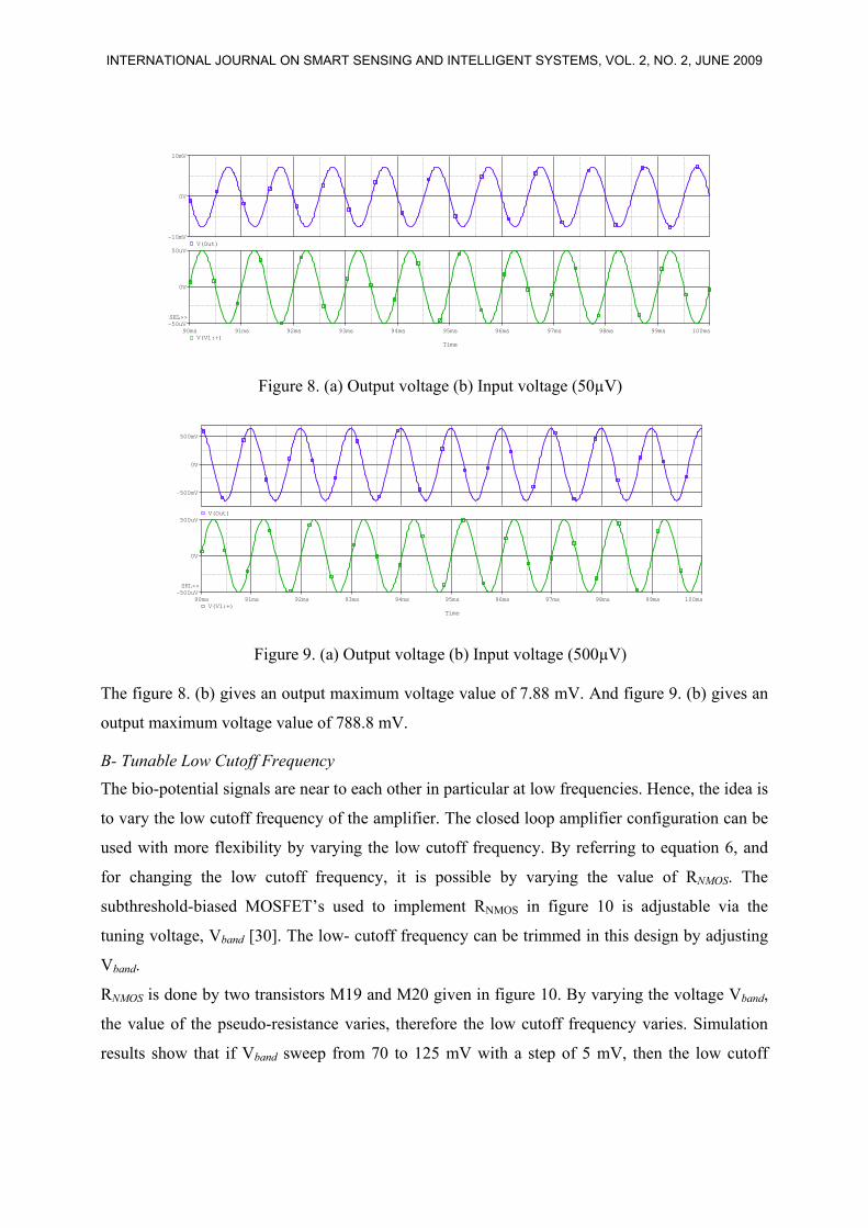
Figure 8. (a) Output voltage (b) Input voltage (50µV)
Time
90ms 91ms 92ms 93ms 94ms 95ms 96ms 97ms 98ms 99ms 100msV(V1:+)
-500uV
0V
500uV
SEL>>
V(Out)
-500mV
0V
500mV
Figure 9. (a) Output voltage (b) Input voltage (500µV)
The figure 8. (b) gives an output maximum voltage value of 7.88 mV. And figure 9. (b) gives an
output maximum voltage value of 788.8 mV.
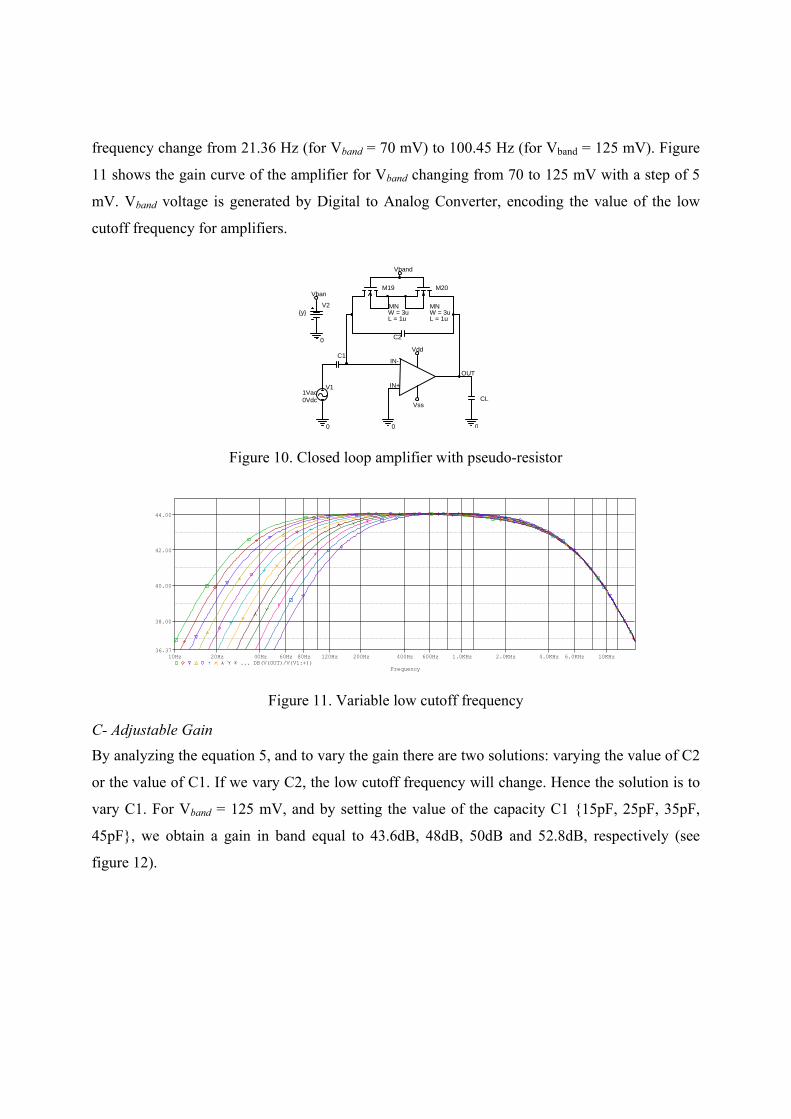
B- Tunable Low Cutoff Frequency The bio-potential signals are near to each other in particular at low frequencies. Hence, the idea is
to vary the low cutoff frequency of the amplifier. The closed loop amplifier configuration can be
used with more flexibility by varying the low cutoff frequency. By referring to equation 6, and
for changing the low cutoff frequency, it is possible by varying the value of RNMOS. The
subthreshold-biased MOSFET’s used to implement RNMOS in figure 10 is adjustable via the
tuning voltage, Vband [30]. The low- cutoff frequency can be trimmed in this design by adjusting
Vband.
RNMOS is done by two transistors M19 and M20 given in figure 10. By varying the voltage Vband,
the value of the pseudo-resistance varies, therefore the low cutoff frequency varies. Simulation
results show that if Vband sweep from 70 to 125 mV with a step of 5 mV, then the low cutoff
INTERNATIONAL JOURNAL ON SMART SENSING AND INTELLIGENT SYSTEMS, VOL. 2, NO. 2, JUNE 2009
Frequency
2.0Hz 4.0Hz 8.0Hz 20Hz 40Hz 60Hz 100Hz 200Hz 400Hz 800Hz 2.0KHz 4.0KHz 8.0KHz 20KHz 40KHz 80KHzDB(V(OUT)/V(V1:+))
20
30
40
50
55
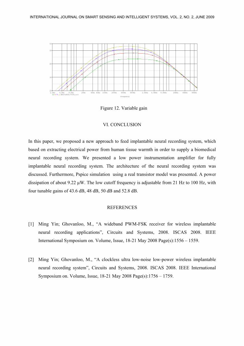
Figure 12. Variable gain
VI. CONCLUSION
In this paper, we proposed a new approach to feed implantable neural recording system, which
based on extracting electrical power from human tissue warmth in order to supply a biomedical
neural recording system. We presented a low power instrumentation amplifier for fully
implantable neural recording system. The architecture of the neural recording system was
discussed. Furthermore, Pspice simulation using a real transistor model was presented. A power
dissipation of about 9.22 μW. The low cutoff frequency is adjustable from 21 Hz to 100 Hz, with
four tunable gains of 43.6 dB, 48 dB, 50 dB and 52.8 dB.
REFERENCES
[1] Ming Yin; Ghovanloo, M., “A wideband PWM-FSK receiver for wireless implantable
neural recording applications”, Circuits and Systems, 2008. ISCAS 2008. IEEE
International Symposium on. Volume, Issue, 18-21 May 2008 Page(s):1556 – 1559.
[2] Ming Yin; Ghovanloo, M., “A clockless ultra low-noise low-power wireless implantable
neural recording system”, Circuits and Systems, 2008. ISCAS 2008. IEEE International
Symposium on. Volume, Issue, 18-21 May 2008 Page(s):1756 – 1759.
INTERNATIONAL JOURNAL ON SMART SENSING AND INTELLIGENT SYSTEMS, VOL. 2, NO. 2, JUNE 2009
[10] Azin, M. Mohseni, P. “A 94-μW 10-b Neural Recording Front-End for an Implantable
Brain-Machine-Brain Interface Device”, Biomedical Circuits and Systems Conference,
2008. BioCAS 2008. IEEE. pp 221-224. 20-22 Nov. 2008.
[11] Aziz, J.N.Y. Abdelhalim, K. Shulyzki, R. Genov, R. Bardakjian, B.L. Derchansky, M.
Serletis, D. Carlen, P.L. “256-Channel Neural Recording and Delta Compression
Microsystem With 3D Electrodes”, Solid-State Circuits, IEEE Journal of. March 2009. Vol.
44, No 3, pp. 995-1005. March 2009.
[12] P. Mohseni, K. Najafi, S. J. Eliades, and X. Wang, “Wireless multichannel biopotential
recording using an integrated FM telemetry circuit,” IEEE Trans. Neural. Syst. Rehab. Eng.,
vol. 13, no. 3, pp. 263-271, September 2005.
[13] Nathan M. Neihart, and Reid R. Harrison, “Micropower Circuits for Bidirectional Wireless
Telemetry in Neural Recording Applications” IEEE Trans. Biomed. Eng., vol. 52, no. 11,
pp. 1950-1959, Nov 2005.
[14] Ming Yin; Ghovanloo, M., “A Clockless Ultra Low-Noise Low-Power Wireless
Implantable Neural Recording System”, Circuits and Systems, 2008. ISCAS 2008. IEEE
International Symposium on. Volume, Issue, 18-21. pp.1756 – 1759, May 2008.
[15] Ghazi BEN HMIDA, Abdennaceur KACHOURI et Hamadi GHARIANI, “Amplificateur
pour l’Acquisition des Signaux Neuronaux dans les Systèmes Implantables”, Proceeding of
5th International Conference: Sciences of Electronic, Technologies of Information and
Telecommunications. SETIT 2009, TUNISIA, March 22-26, 2009.
[16] Ghazi BEN HMIDA, Abdennaceur KACHOURI and Hamadi GHARIANI GHARIANI,
“Design of a Micro Power Amplifier for Neural Signal Recording”, Proceeding of Sixth
International Multi-Conference on Systems, Signals & Devices (SSD) 2009. International
Conference on Sensors, Circuits and Instrumentation Systems, Djerba – Tunisia, March 23-
26, 2009.
INTERNATIONAL JOURNAL ON SMART SENSING AND INTELLIGENT SYSTEMS, VOL. 2, NO. 2, JUNE 2009
[25] V. Leonov, unpublished. See also: Z. Wang, V. Leonov, P. Fiorini, C. Van Hoof,
“Micromachined thermopiles for energy scavenging on human body”, Int. Conf. On Solid-
State Sensors, Actuators and Microsystems TRANSDUCERS 2007. 10-14 June 2007, pp.
911-914.
[26] V. Leonov, T. Torfs, P. Fiorini, C. Van Hoof, ”Thermoelectric converters of human warmth
for self-powered wireless sensor nodes”, IEEE Sensors Journal, pp. 650 – 657, 2007.
[27] J.F. Dickson, “On-chip high-voltage generation in MNOS integrated circuits using an
improved voltage multiplier technique”, IEEE Journal of Solid-State Circuits, vol. 11(3), pp.
374-378, June 1976.
[28] V. Leonov and P. Fiorini, ”Thermal matching of a thermoelectric energy scavenger with the
ambient”, Proceedings 5th European Conference on Thermoelectrics, 10-12 September
2007 Odessa (Ukraine), pp. 129-133.
[29] R. R. Harrison and C. Charles, “A low-power low-noise CMOS amplifier for neural
recording applications”, IEEE J. Solid-State Circuits, vol. 38, pp. 958 965, June 2003.
[30] Olsson, R.H., III Buhl, D.L. Sirota, A.M. Buzsaki, G. Wise, K.D. “Band tunable and
multiplexed integrated circuits for simultaneous recording and stimulation with
microelectrode arrays”. Biomedical Engineering, IEEE Transactions on. Vol. 52, No: 7. pp.
1303-1311. July 2005.
INTERNATIONAL JOURNAL ON SMART SENSING AND INTELLIGENT SYSTEMS, VOL. 2, NO. 2, JUNE 2009