Embed Size (px)
Citation preview
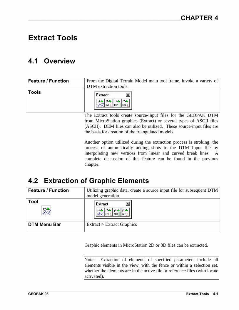
_____________________________________________________________________________CHAPTER 4
GEOPAK 98 Extract Tools 4-1
Extract Tools
4.1 Overview
Feature / Function From the Digital Terrain Model main tool frame, invoke a variety ofDTM extraction tools.
Tools
The Extract tools create source-input files for the GEOPAK DTMfrom MicroStation graphics (Extract) or several types of ASCII files(ASCII). DEM files can also be utilized. These source-input files arethe basis for creation of the triangulated models.
Another option utilized during the extraction process is stroking, theprocess of automatically adding shots to the DTM Input file byinterpolating new vertices from linear and curved break lines. Acomplete discussion of this feature can be found in the previouschapter.
4.2 Extraction of Graphic ElementsFeature / Function Utilizing graphic data, create a source input file for subsequent DTM
model generation.Tool
DTM Menu Bar Extract > Extract Graphics
Graphic elements in MicroStation 2D or 3D files can be extracted.
Note: Extraction of elements of specified parameters include allelements visible in the view, with the fence or within a selection set,whether the elements are in the active file or reference files (with locateactivated).
~__________________________________________________________________________________________
4-2 GeoTerrain by GEOPAK User's Guide GEOPAK 98
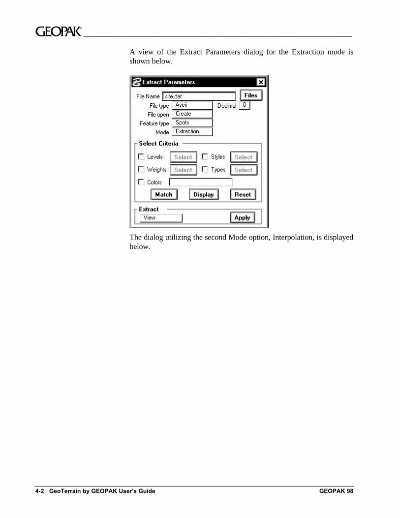
A view of the Extract Parameters dialog for the Extraction mode isshown below.
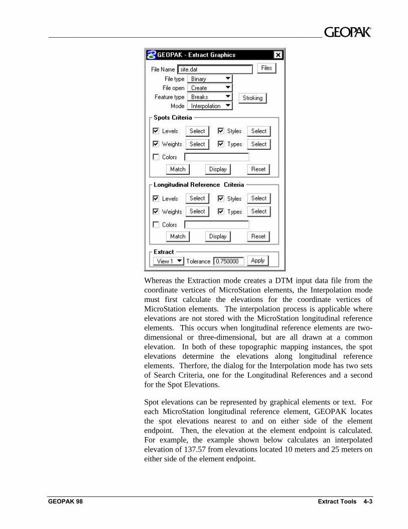
The dialog utilizing the second Mode option, Interpolation, is displayedbelow.
__________________________________________________________________________________________ ~
GEOPAK 98 Extract Tools 4-3
Whereas the Extraction mode creates a DTM input data file from thecoordinate vertices of MicroStation elements, the Interpolation modemust first calculate the elevations for the coordinate vertices ofMicroStation elements. The interpolation process is applicable whereelevations are not stored with the MicroStation longitudinal referenceelements. This occurs when longitudinal reference elements are two-dimensional or three-dimensional, but are all drawn at a commonelevation. In both of these topographic mapping instances, the spotelevations determine the elevations along longitudinal referenceelements. Therfore, the dialog for the Interpolation mode has two setsof Search Criteria, one for the Longitudinal References and a secondfor the Spot Elevations.
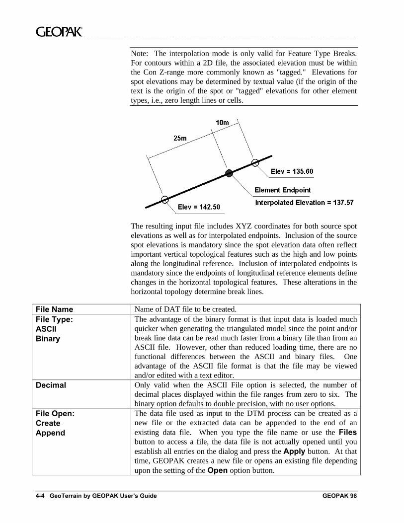
Spot elevations can be represented by graphical elements or text. Foreach MicroStation longitudinal reference element, GEOPAK locatesthe spot elevations nearest to and on either side of the elementendpoint. Then, the elevation at the element endpoint is calculated.For example, the example shown below calculates an interpolatedelevation of 137.57 from elevations located 10 meters and 25 meters oneither side of the element endpoint.
~__________________________________________________________________________________________
4-4 GeoTerrain by GEOPAK User's Guide GEOPAK 98
Note: The interpolation mode is only valid for Feature Type Breaks.For contours within a 2D file, the associated elevation must be withinthe Con Z-range more commonly known as "tagged." Elevations forspot elevations may be determined by textual value (if the origin of thetext is the origin of the spot or "tagged" elevations for other elementtypes, i.e., zero length lines or cells.
The resulting input file includes XYZ coordinates for both source spotelevations as well as for interpolated endpoints. Inclusion of the sourcespot elevations is mandatory since the spot elevation data often reflectimportant vertical topological features such as the high and low pointsalong the longitudinal reference. Inclusion of interpolated endpoints ismandatory since the endpoints of longitudinal reference elements definechanges in the horizontal topological features. These alterations in thehorizontal topology determine break lines.
File Name Name of DAT file to be created.File Type:ASCIIBinary
The advantage of the binary format is that input data is loaded muchquicker when generating the triangulated model since the point and/orbreak line data can be read much faster from a binary file than from anASCII file. However, other than reduced loading time, there are nofunctional differences between the ASCII and binary files. Oneadvantage of the ASCII file format is that the file may be viewedand/or edited with a text editor.
Decimal Only valid when the ASCII File option is selected, the number ofdecimal places displayed within the file ranges from zero to six. Thebinary option defaults to double precision, with no user options.
File Open:CreateAppend
The data file used as input to the DTM process can be created as anew file or the extracted data can be appended to the end of anexisting data file. When you type the file name or use the Filesbutton to access a file, the data file is not actually opened until youestablish all entries on the dialog and press the Apply button. At thattime, GEOPAK creates a new file or opens an existing file dependingupon the setting of the Open option button.
__________________________________________________________________________________________ ~
GEOPAK 98 Extract Tools 4-5
If the Open option button is set to Create and the file already exists,an Alert dialog appears with the message "Overwrite existing <filename>?" when the Apply button is pressed. If you press OK, theexisting file is overwritten. Pressing the Cancel button permits youto return to the main Extract dialog and readjust the file name or openmode.If the Open option button is set to Append and the file does notexist, an Alert dialog appears with the message "Create <file name>?"when the Apply button is pressed. Pressing OK results in thecreation of the specified file. Pressing Cancel returns control back tothe main Extract dialog.
Feature Types:SpotsBreaksContoursVoidsBoundaryIslandGraphic TriangleDrape Void
Spots are points that have no functional relationship to any otherpoint. Random survey shots in open terrain would be an example ofrandom spots. Point elements such as cells, circles, and text stringsare typical MicroStation elements used to define spot elevations.Lines, line strings, and other longitudinal elements are equally valid.GEOPAK simply creates a spot elevation for each vertex of eachlongitudinal element.Breaks are used to designate linear features such as edges ofpavement, ditch bottoms, ridges, etc. Any longitudinal element maybe defined as a break line. Circular arcs are automatically segmentedby GEOPAK in a manner consistent with the arc radius.Contours are a special feature intended for use if the sourceMicroStation elements represent digitized or otherwise createdcontours. Use of this feature insures the integrity of the contour stratain the subsequent DTM. Processing of a DTM with contoursclassified as spot elevations invariably results in a DTM that, ifsubsequently contoured, will not match the original extractedcontours.Void areas are closed shapes to demarcate areas of missing data orobscure areas. No point or break data located within the void area isutilized and no triangles are created inside the void areas.Boundary are used to constrain the external boundary of thetriangulated model. No triangles are created outside the boundarypolygon. In addition, any point data outside the boundary polygon isignored. A boundary polygon must start and finish with the samepoint. In addition, the boundary polygon must be continuous withinthe data file.Island - are used to place data within a void, i.e., islands in themiddle of rivers, lakes, etc.Graphic triangles - by extracting as triangles, a vertex which is locatedon several triangles is only extracted once, not once on each triangle.Drape Void - A void utilizes the elevations of each vertex, while inthe drape void, the element is draped onto the model, therebyascertaining its elevation from the model, rather than the drape void
~__________________________________________________________________________________________
4-6 GeoTerrain by GEOPAK User's Guide GEOPAK 98
elements. It is then inserted into the model.ModeExtraction orInterpolation
The Extraction mode determines XYZ data directly from thecoordinate values of three-dimensional MicroStation elements. TheInterpolation mode, by contrast, derives XYZ data by locating spotelevations on longitudinal MicroStation elements and interpolating.Hence, the Interpolation mode can be applied to both two-dimensionalas well as three-dimensional MicroStation files as long as a Z-coordinate reading can be ascertained from the spot elevations.
Stroking Utilized in the interpolation mode, this shortcut to the Settings >Stroking dialog may be used. Changing the dialog from eitherlocation automatically updates the dialog in the other location. For adetailed discussion, refer to the Settings > Stroking documentation.
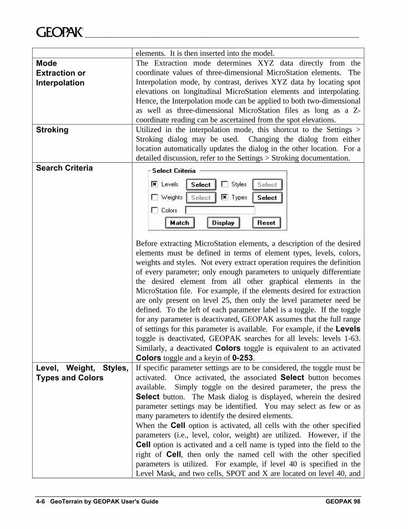
Search Criteria
Before extracting MicroStation elements, a description of the desiredelements must be defined in terms of element types, levels, colors,weights and styles. Not every extract operation requires the definitionof every parameter; only enough parameters to uniquely differentiatethe desired element from all other graphical elements in theMicroStation file. For example, if the elements desired for extractionare only present on level 25, then only the level parameter need bedefined. To the left of each parameter label is a toggle. If the togglefor any parameter is deactivated, GEOPAK assumes that the full rangeof settings for this parameter is available. For example, if the Levelstoggle is deactivated, GEOPAK searches for all levels: levels 1-63.Similarly, a deactivated Colors toggle is equivalent to an activatedColors toggle and a keyin of 0-253.
Level, Weight, Styles,Types and Colors
If specific parameter settings are to be considered, the toggle must beactivated. Once activated, the associated Select button becomesavailable. Simply toggle on the desired parameter, the press theSelect button. The Mask dialog is displayed, wherein the desiredparameter settings may be identified. You may select as few or asmany parameters to identify the desired elements.When the Cell option is activated, all cells with the other specifiedparameters (i.e., level, color, weight) are utilized. However, if theCell option is activated and a cell name is typed into the field to theright of Cell, then only the named cell with the other specifiedparameters is utilized. For example, if level 40 is specified in theLevel Mask, and two cells, SPOT and X are located on level 40, and

__________________________________________________________________________________________ ~
GEOPAK 98 Extract Tools 4-7
no cell name is specified in the cell field, then both cells are extracted.However, if SPOT is typed into the field, then only the SPOT cells areextracted, although other cells are located on level 40.The Text String also has two options: Origin and Content. Whenthe Text String toggle is activated and the option set to Origin,GEOPAK utilizes the origin of the text as the x,y,z coordinates forextraction. If the Content option is specified, the x,y coordinates arederived from the text origin. However, the z value is not the z valuewithin a 3D file, but the actual value of the text, whether a 2D or 3Dfile.
Match The Match tool is a method of determining and adding the symbologyof elements to be extracted to the Mask dialogs. First, activate thedesired toggle(s) to the left of the Search Criteria. Then press theMatch button. You are prompted to select the desired element.After identifying and accepting the element, its search criteria is addedto any criteria whose toggle is activated. In addition, any elements ofthe specified parameters are highlighted. The Match button can beutilized numerous times to select additional elements. The informationis appended to the Mask dialogs until the Reset button in the dialogis pressed.
Display Pressing the Display button displays all shapes of the currentparameters.
Reset The Reset button clears all Mask dialogs, so a new match proceduremay commence.
Tolerance(Interpolation mode only)default = 0.75 master units
If a spot elevation is within 0.75 master units of a longitudinalreference, the software projects the spot onto the reference(perpendicular) and uses the elevation to interpolate.
Extract Method:View 1, 2, …….FenceComplex Chain, orSelection Set
The View method extracts every element that is visible in thespecified active view and satisfies the selection criteria. This includeselements in both the active as well as reference files if the Locate isactivated. Simply set the desired View number before pressing theApply button.The Fence method extracts every element that satisfies both thefence criteria as well as the selection criteria defined via the SelectCriteria group box. All MicroStation fence options are supported.Place the Fence prior to pressing the Apply button.Complex Chain - The Select Criteria group box disappears from thedialog, since you identify the elements via the cursor; and no file-widesearches are involved. Also, notice that the ID Element buttonappears adjacent to the Extract method option button. This buttoninitiates the "chaining" of MicroStation elements. The followingoutlines the sequence of operations associated with the ComplexChain method.1. Establish the desired dialog settings.
~__________________________________________________________________________________________
4-8 GeoTerrain by GEOPAK User's Guide GEOPAK 98
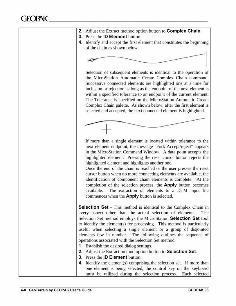
2. Adjust the Extract method option button to Complex Chain.3. Press the ID Element button.4. Identify and accept the first element that constitutes the beginning
of the chain as shown below.
Selection of subsequent elements is identical to the operation ofthe MicroStation Automatic Create Complex Chain command.Successive connected elements are highlighted one at a time forinclusion or rejection as long as the endpoint of the next element iswithin a specified tolerance to an endpoint of the current element.The Tolerance is specified on the MicroStation Automatic CreateComplex Chain palette. As shown below, after the first element isselected and accepted, the next connected element is highlighted.
If more than a single element is located within tolerance to thenext element endpoint, the message "Fork Accept/reject" appearsin the MicroStation Command Window. A data point accepts thehighlighted element. Pressing the reset cursor button rejects thehighlighted element and highlights another one.Once the end of the chain is reached or the user presses the resetcursor button when no more connecting elements are available, theidentification of component chain elements is complete. At thecompletion of the selection process, the Apply button becomesavailable. The extraction of elements to a DTM input filecommences when the Apply button is selected.
Selection Set - This method is identical to the Complex Chain inevery aspect other than the actual selection of elements. TheSelection Set method employs the MicroStation Selection Set toolto identify the element(s) for processing. This method is particularlyuseful when selecting a single element or a group of disjointedelements few in number. The following outlines the sequence ofoperations associated with the Selection Set method.1. Establish the desired dialog settings.2. Adjust the Extract method option button to Selection Set.3. Press the ID Element button.4. Identify the element(s) comprising the selection set. If more than
one element is being selected, the control key on the keyboardmust be utilized during the selection process. Each selected
__________________________________________________________________________________________ ~
GEOPAK 98 Extract Tools 4-9
element can be identified by the small, solid rectangles at each endof the selected elements.
5. At the completion of the selection process, the Apply buttonbecomes available. The extraction of elements to a DTM input filecommences when the Apply button is selected.
Apply Commences the extraction procedure. Note that the dialog should befilled in completely, and the Extract mode selected and applicablefence, view, selection set or complex chain identified prior to pressingthe Apply button.
4.3 Extracting Set FormatFeature / Function Utilizing specialized ASCII files generated from other software
programs, create a source input file for subsequent DTM modelgeneration.
Tool
DTM Menu Bar Extract > Extract Set Format
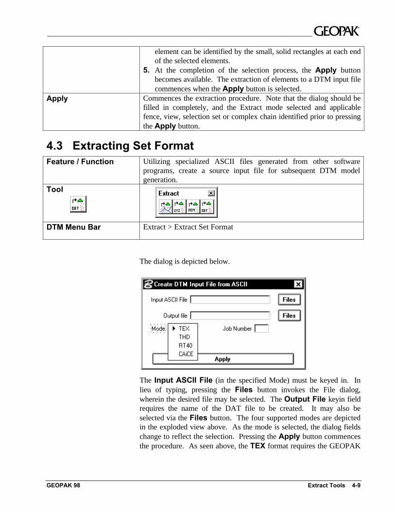
The dialog is depicted below.
The Input ASCII File (in the specified Mode) must be keyed in. Inlieu of typing, pressing the Files button invokes the File dialog,wherein the desired file may be selected. The Output File keyin fieldrequires the name of the DAT file to be created. It may also beselected via the Files button. The four supported modes are depictedin the exploded view above. As the mode is selected, the dialog fieldschange to reflect the selection. Pressing the Apply button commencesthe procedure. As seen above, the TEX format requires the GEOPAK
~__________________________________________________________________________________________
4-10 GeoTerrain by GEOPAK User's Guide GEOPAK 98
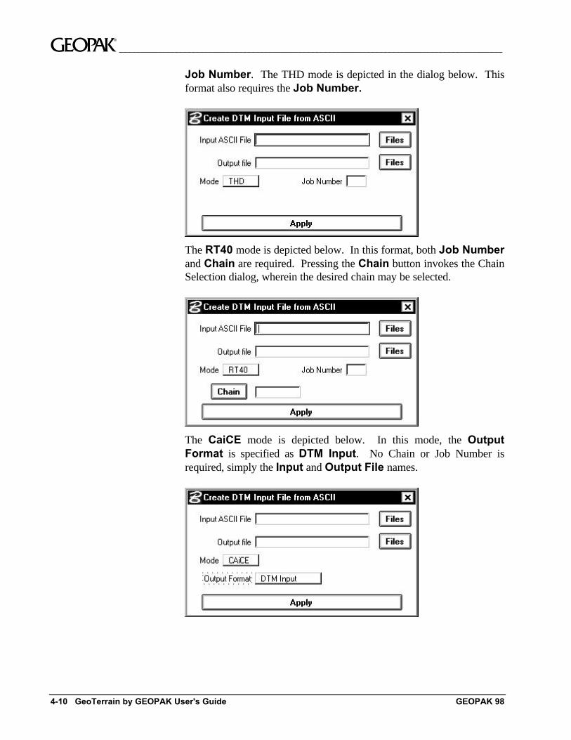
Job Number. The THD mode is depicted in the dialog below. Thisformat also requires the Job Number.
The RT40 mode is depicted below. In this format, both Job Numberand Chain are required. Pressing the Chain button invokes the ChainSelection dialog, wherein the desired chain may be selected.
The CaiCE mode is depicted below. In this mode, the OutputFormat is specified as DTM Input. No Chain or Job Number isrequired, simply the Input and Output File names.
__________________________________________________________________________________________ ~
GEOPAK 98 Extract Tools 4-11
4.4 Extracting ASCII FormatFeature / Function Utilizing generic ASCII files, create a source input file for subsequent
DTM model generation.Tool
DTM Menu Bar Extract > Extract ASCII
The Extract ASCII Format tool supports most any ASCII filecontaining reduced survey data or even just XYZ data. DTM inputfiles can be derived from a file containing XYZ data with no pointcodes. Other features include embedded Linking Codes and FeatureCodes, support for linking together shots based upon defined chains,support for comments and support for the situation where the user doesnot have a “continuation” linking code for each shot but wants theseshots connected. These ASCII files need not conform to any particularstructure or format other than a requirement that each point entry berestricted to a single row. The ASCII file should not contain more thanone point per row. Similarly, multiple rows should not be required todefine a single point code.
Within the row containing point code data, virtually no restrictions areplaced on the arrangement and separation of survey data. Individualdata items (point code, x-coordinate, y-coordinate, z-coordinate, pointnumber) can be arranged in either free form or column formats. Inaddition, extraneous information may be present in the row and ignoredby GEOPAK. Data items in the free form format can be separated byspaces, commas, dashes, etc.
Two steps are required to extract ASCII data:
1) Load the ASCII file.2) Identify how the data items are arranged.
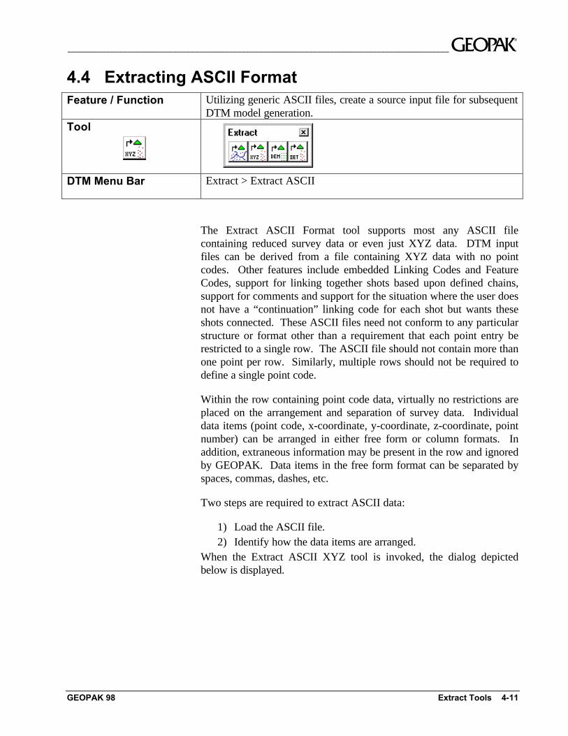
When the Extract ASCII XYZ tool is invoked, the dialog depictedbelow is displayed.
~__________________________________________________________________________________________
4-12 GeoTerrain by GEOPAK User's Guide GEOPAK 98
4.4.1 Setting up the ASCII File
The name of the ASCII file may be typed directly into the input fieldlabeled File or may be accessed via the File button. Pressing the Filebutton invokes the standard MicroStation dialog box used for filesretrieval. The ASCII file need not be in the current directory.
Once the survey file is retrieved, the first few lines are displayed in thelist box labeled Contents of File as depicted in the graphic above.
GEOPAK requires the following information for each data point:Point Code, X-coordinate, Y-coordinate and Z-coordinate.Other informational items include Point Number, Linking Code,Chain, DTM, Zone, and combination Linking Code Point Code.
The first step in assigning fields is to set the delimiter option button tothe correct delimiter separating the free format fields. Variousdelimiters include the comma, dash, slash, semi-colon and space. Ifnone of these satisfy your needs, you can select the Other field. Inresponse to the Other selection, GEOPAK prompts for the delimitercharacter.
Once the correct delimiter has been specified, the second step is tosingle click onto a line of data. The individual items fields will appearover the series of option buttons located beneath the list box as shownbelow.
__________________________________________________________________________________________ ~
GEOPAK 98 Extract Tools 4-13
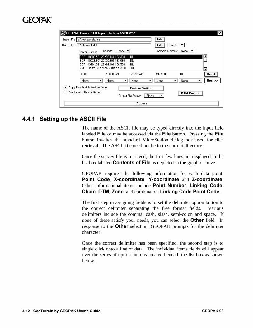
The third step is to identify the individual fields in the data file asrepresenting either a point code, point number, x-coordinate, y-coordinate or z-coordinate. (An exploded view of the option button isdepicted below.)
To accomplish this, adjust the option button to correctly identify thefunction of each associated field from the survey file. For the samplecase shown below, the option buttons appear in the following order:Point Code (PCode), X, Y, and Z.
~__________________________________________________________________________________________
4-14 GeoTerrain by GEOPAK User's Guide GEOPAK 98
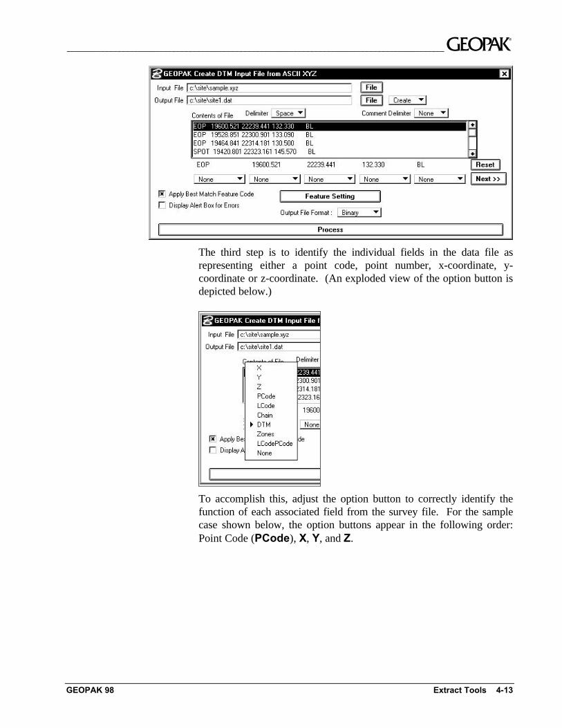
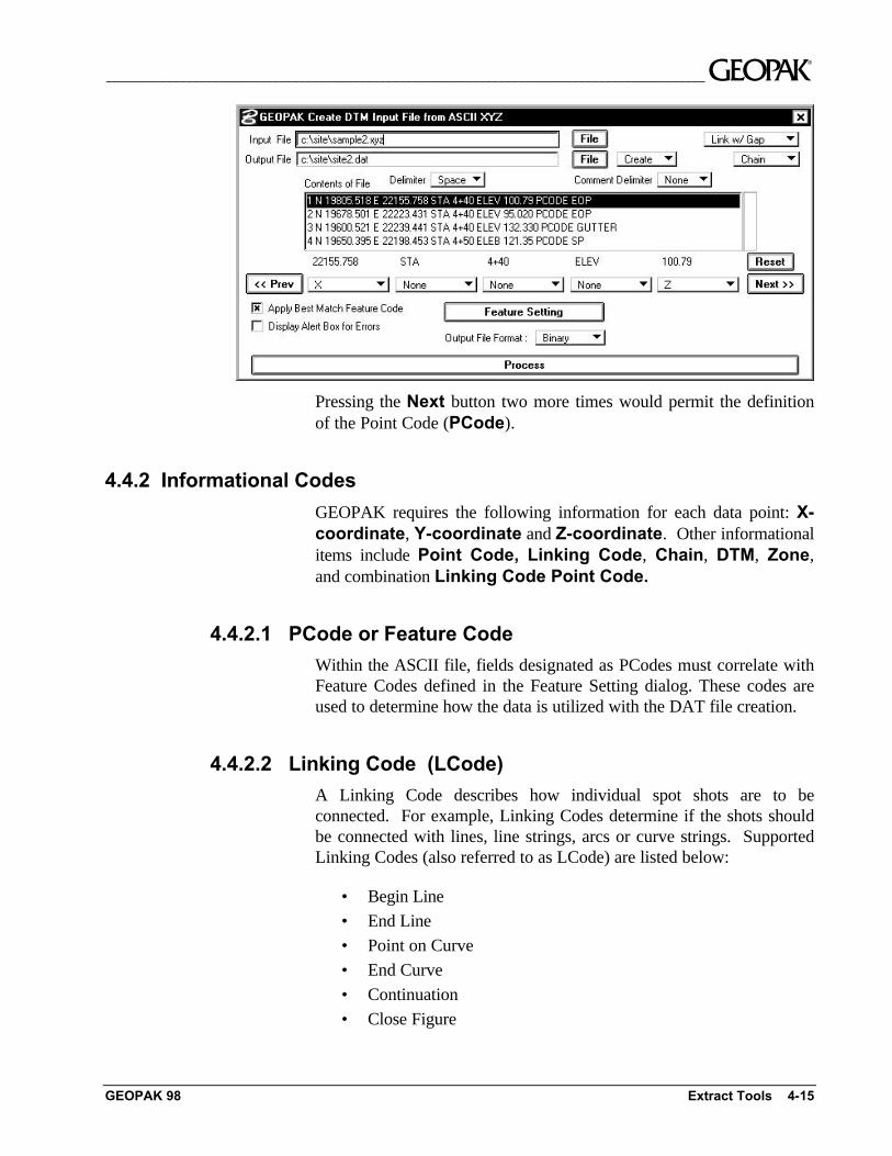
Yet, another case might involve a considerable number of extraneousentries in the survey file. The data file depicted below contains elevenseparate fields.
1 N 19805.518 E 22155.758 STA 4+40 ELEV 100.79 PCode PL(B)2 N 19678.501 E 22223,431 STA 4+40 ELEV 95.020 PCode PL(B)3 N 19600.521 E 22239.441 STA 4+40 ELEV 134.330 PCode PL(B)
Since the dialog permits the definition of only five fields at a time, wemust make use of the Previous and Next buttons to shift the fieldsright and left. Prior to pressing the Next button, adjust the optionbuttons to the appropriate settings. The first field represents the pointnumber and, hence, is set to None. The next field contains the letter"N" identifying the following coordinate as a northing. Hence, theoption button below the "N" is set to None. After adjusting the fiveoption buttons and pressing the Next button four times, the dialogwould appear as shown below. The X coordinate has now shifted fromthe fifth to the first option button. Subsequent assignment of the otherfour option buttons would be None for the station label, station value,and elevation label. The option button below the elevation value wouldbe set to Z as shown below.
__________________________________________________________________________________________ ~
GEOPAK 98 Extract Tools 4-15
Pressing the Next button two more times would permit the definitionof the Point Code (PCode).
4.4.2 Informational Codes
GEOPAK requires the following information for each data point: X-coordinate, Y-coordinate and Z-coordinate. Other informationalitems include Point Code, Linking Code, Chain, DTM, Zone,and combination Linking Code Point Code.
4.4.2.1 PCode or Feature Code
Within the ASCII file, fields designated as PCodes must correlate withFeature Codes defined in the Feature Setting dialog. These codes areused to determine how the data is utilized with the DAT file creation.
4.4.2.2 Linking Code (LCode)
A Linking Code describes how individual spot shots are to beconnected. For example, Linking Codes determine if the shots shouldbe connected with lines, line strings, arcs or curve strings. SupportedLinking Codes (also referred to as LCode) are listed below:
• Begin Line
• End Line
• Point on Curve
• End Curve
• Continuation
• Close Figure
~__________________________________________________________________________________________
4-16 GeoTerrain by GEOPAK User's Guide GEOPAK 98
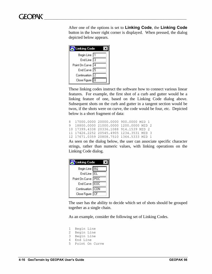
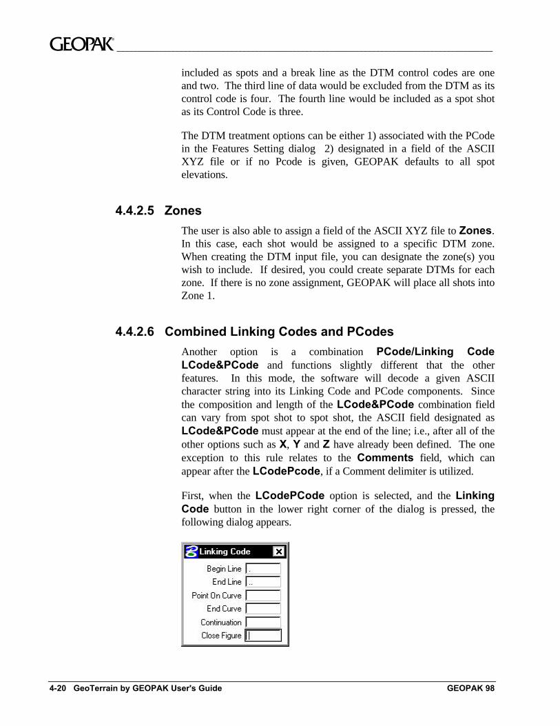
After one of the options is set to Linking Code, the Linking Codebutton in the lower right corner is displayed. When pressed, the dialogdepicted below appears.
These linking codes instruct the software how to connect various linearfeatures. For example, the first shot of a curb and gutter would be alinking feature of one, based on the Linking Code dialog above.Subsequent shots on the curb and gutter in a tangent section would betwos, if the shots were on curve, the code would be four, etc. Depictedbelow is a short fragment of data:
8 17000.0000 20000.0000 900.0000 MID 19 18800.0000 21000.0000 1200.0000 MID 210 17399.4338 20336.1088 914.1539 MID 211 17426.2252 20545.4905 1234.3531 MID 312 17671.0359 20808.7510 1364.5333 MID 1
As seen on the dialog below, the user can associate specific characterstrings, rather than numeric values, with linking operations on theLinking Code dialog.
The user has the ability to decide which set of shots should be groupedtogether as a single chain.
As an example, consider the following set of Linking Codes.
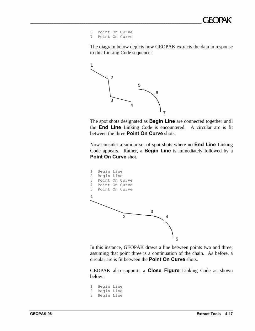
1 Begin Line2 Begin Line3 Begin Line4 End Line5 Point On Curve
__________________________________________________________________________________________ ~
GEOPAK 98 Extract Tools 4-17
6 Point On Curve7 Point On Curve
The diagram below depicts how GEOPAK extracts the data in responseto this Linking Code sequence:
1
2
34
5
6
7
The spot shots designated as Begin Line are connected together untilthe End Line Linking Code is encountered. A circular arc is fitbetween the three Point On Curve shots.
Now consider a similar set of spot shots where no End Line LinkingCode appears. Rather, a Begin Line is immediately followed by aPoint On Curve shot.
1 Begin Line2 Begin Line3 Point On Curve4 Point On Curve5 Point On Curve
1
23
4
5
In this instance, GEOPAK draws a line between points two and three;assuming that point three is a continuation of the chain. As before, acircular arc is fit between the Point On Curve shots.
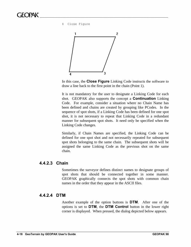
GEOPAK also supports a Close Figure Linking Code as shownbelow:
1 Begin Line2 Begin Line3 Begin Line
~__________________________________________________________________________________________
4-18 GeoTerrain by GEOPAK User's Guide GEOPAK 98
4 Close Figure
In this case, the Close Figure Linking Code instructs the software todraw a line back to the first point in the chain (Point 1).
It is not mandatory for the user to designate a Linking Code for eachshot. GEOPAK also supports the concept a Continuation LinkingCode. For example, consider a situation where no Chain Name hasbeen defined and chains are created by grouping like PCodes. In thesequence of spot shots, if a Linking Code has been defined for one spotshot, it is not necessary to repeat that Linking Code in a redundantmanner for subsequent spot shots. It need only be specified when theLinking Code changes.
Similarly, if Chain Names are specified, the Linking Code can bedefined for one spot shot and not necessarily repeated for subsequentspot shots belonging to the same chain. The subsequent shots will beassigned the same Linking Code as the previous shot on the samechain.
4.4.2.3 Chain
Sometimes the surveyor defines distinct names to designate groups ofspot shots that should be connected together in some manner.GEOPAK graphically connects the spot shots with common chainnames in the order that they appear in the ASCII files.
4.4.2.4 DTM
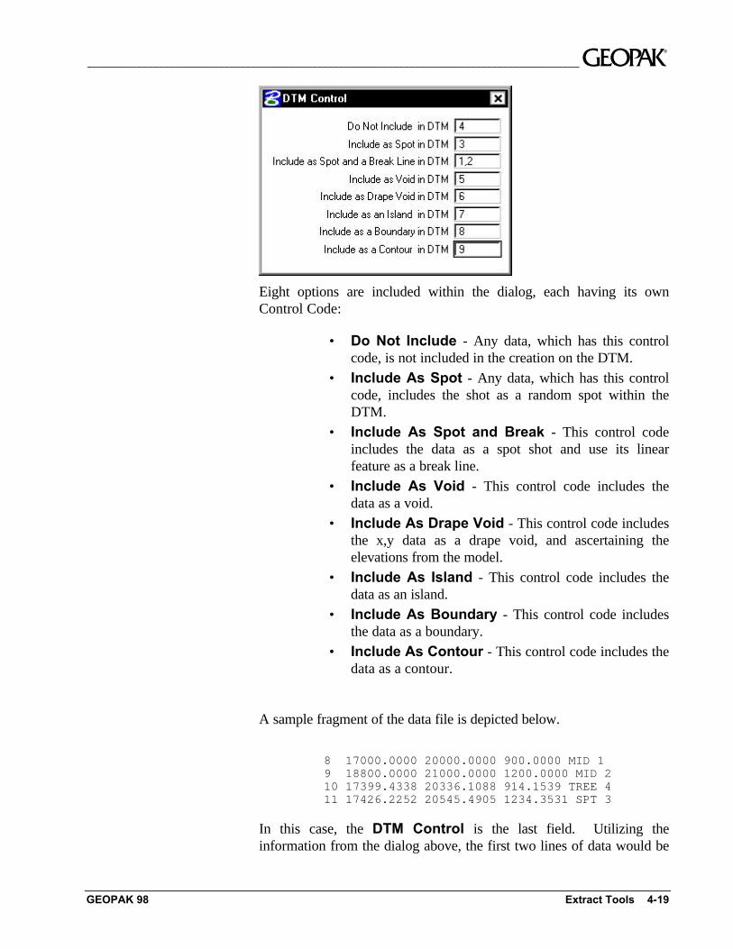
Another example of the option buttons is DTM. After one of theoptions is set to DTM, the DTM Control button in the lower rightcorner is displayed. When pressed, the dialog depicted below appears.
__________________________________________________________________________________________ ~
GEOPAK 98 Extract Tools 4-19
Eight options are included within the dialog, each having its ownControl Code:
• Do Not Include - Any data, which has this controlcode, is not included in the creation on the DTM.
• Include As Spot - Any data, which has this controlcode, includes the shot as a random spot within theDTM.
• Include As Spot and Break - This control codeincludes the data as a spot shot and use its linearfeature as a break line.
• Include As Void - This control code includes thedata as a void.
• Include As Drape Void - This control code includesthe x,y data as a drape void, and ascertaining theelevations from the model.
• Include As Island - This control code includes thedata as an island.
• Include As Boundary - This control code includesthe data as a boundary.
• Include As Contour - This control code includes thedata as a contour.
A sample fragment of the data file is depicted below.
8 17000.0000 20000.0000 900.0000 MID 19 18800.0000 21000.0000 1200.0000 MID 210 17399.4338 20336.1088 914.1539 TREE 411 17426.2252 20545.4905 1234.3531 SPT 3
In this case, the DTM Control is the last field. Utilizing theinformation from the dialog above, the first two lines of data would be
~__________________________________________________________________________________________
4-20 GeoTerrain by GEOPAK User's Guide GEOPAK 98
included as spots and a break line as the DTM control codes are oneand two. The third line of data would be excluded from the DTM as itscontrol code is four. The fourth line would be included as a spot shotas its Control Code is three.
The DTM treatment options can be either 1) associated with the PCodein the Features Setting dialog 2) designated in a field of the ASCIIXYZ file or if no Pcode is given, GEOPAK defaults to all spotelevations.
4.4.2.5 Zones
The user is also able to assign a field of the ASCII XYZ file to Zones.In this case, each shot would be assigned to a specific DTM zone.When creating the DTM input file, you can designate the zone(s) youwish to include. If desired, you could create separate DTMs for eachzone. If there is no zone assignment, GEOPAK will place all shots intoZone 1.
4.4.2.6 Combined Linking Codes and PCodes
Another option is a combination PCode/Linking CodeLCode&PCode and functions slightly different that the otherfeatures. In this mode, the software will decode a given ASCIIcharacter string into its Linking Code and PCode components. Sincethe composition and length of the LCode&PCode combination fieldcan vary from spot shot to spot shot, the ASCII field designated asLCode&PCode must appear at the end of the line; i.e., after all of theother options such as X, Y and Z have already been defined. The oneexception to this rule relates to the Comments field, which canappear after the LCodePcode, if a Comment delimiter is utilized.
First, when the LCodePCode option is selected, and the LinkingCode button in the lower right corner of the dialog is pressed, thefollowing dialog appears.
__________________________________________________________________________________________ ~
GEOPAK 98 Extract Tools 4-21
In each field, enter the text string utilized for each Linking Code. Notethat only those fields utilized in the data must have entries. In ourexample, we only have Begin Line (.) and End Line (..) defined asour data has none of the other codes.
Below is a fragment of a sample data file.
1000 252825.564 336994.498 100.616000 .1011001 252835.354 336994.086 100.182000 .1011002 252841.553 336996.280 99.4940000 ..101.1041003 252849.420 337004.238 94.5180000 .1041004 252857.567 337009.067 97.5970000 ..104.101
Note that the LCode&PCode sequence is at the end of the line.Since the length of the field is variable, and spaces are supported,GEOPAK utilizes all information from the first LCode&PCodecharacter onward. Therefore, this option cannot be placed in themiddle of the file, for example, before the Z coordinates. It wouldassume everything to the right would be part of the PCode/LinkingCode including the Z coordinates. In the data above, the first line is abegin line (based on the . from the dialog above) for PCode 101. Linetwo is also a begin line for 101. The third line is an end line for 101and a begin line for 104. Therefore, these three lines would draw a linefrom the first line, through the second shot and stop and the third shot.At this point PCode 104 begins a line.
The decoding of the combined LCode&PCode is a two step process.First, the user defines a set of Linking Code strings via the LinkingCode dialog box. GEOPAK searches for these strings and separatesLinking Code strings from the PCodes. For example:
… LC1 PCode1 LC2 PCode2… LC1PCode1LC2PCode2
The first Linking Code (LC1) is associated with PCode1 and thesecond Linking Code (LC2) is associated with PCode2 and so on.GEOPAK attempts to pair the Linking Codes and PCodes from left toright.
… LC1 PCode1 PCode2… LC1PCode1 PCode2… PCode1LC1PCode2
Linking Code (LC1) would be applied to those PCodes that aredefined in the Feature Setting dialog with the Linking Code optionselected. GEOPAK references the Feature Setting dialog to determineif Linear Features were defined for PCode1 and/or Pcode2. Hence,

~__________________________________________________________________________________________
4-22 GeoTerrain by GEOPAK User's Guide GEOPAK 98
in the example above, if PCode1 was defined with the Linking Codetoggle active while PCode2 was defined with the Linking Code togglenot active, then the Linking Code (LC1) would be applied only toPCode1.
4.4.2.7 Comments
GEOPAK also supports Comments. The comment must be precededby a specific, user defined delimiter. The user can establish thisdelimiter via the Comment Delimiter field contained on the dialogwhereupon the various ASCII fields are designated. The only conditionis that this delimiter must be different from the primary delimiter usedto distinguish between the various ASCII fields Moreover, theComment Delimiter as well as the content of the comment must becontiguous.
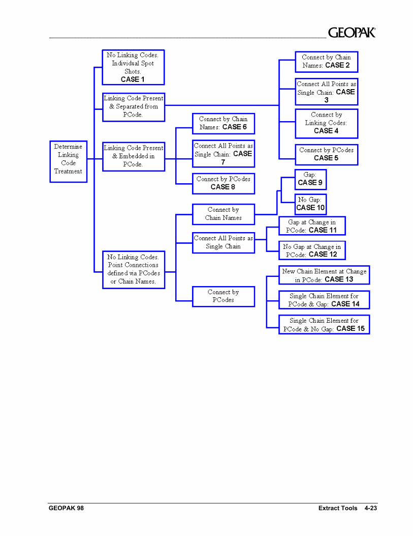
4.4.3 Decision Making Procedures
The graphic on the next page offers a Decision Tree whereby the usercan determine the proper settings on the ASCII XYZ dialog for specificdata sets. This Decision Tree is organized in terms of specific data setformats. Primary determinants include the following:
• Presence of Linking Codes
• Designation of Chain Names
• Gaps: Extract connecting geometry between points belongingto the same Chain or PCode but which are not contiguous in theASCII file.
• No Gaps: Do not extract connecting geometry in instanceswhere points belong to the same Chain or PCode but are notcontiguous in the ASCII file.
Subsections following the Decision Tree detail each of the 15 cases.
__________________________________________________________________________________________ ~
GEOPAK 98 Extract Tools 4-23
~__________________________________________________________________________________________
4-24 GeoTerrain by GEOPAK User's Guide GEOPAK 98
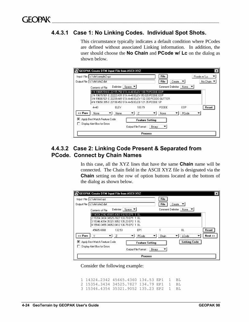
4.4.3.1 Case 1: No Linking Codes. Individual Spot Shots.
This circumstance typically indicates a default condition where PCodesare defined without associated Linking information. In addition, theuser should choose the No Chain and PCode w/ Lc on the dialog asshown below.
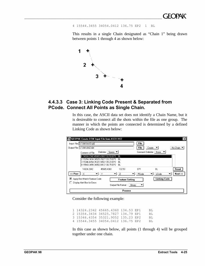
4.4.3.2 Case 2: Linking Code Present & Separated fromPCode. Connect by Chain Names
In this case, all the XYZ lines that have the same Chain name will beconnected. The Chain field in the ASCII XYZ file is designated via theChain setting on the row of option buttons located at the bottom ofthe dialog as shown below.
Consider the following example:
1 14324.2342 45665.4360 134.53 EP1 1 BL2 15354.3434 34525.7827 134.79 EP1 1 BL3 15346.4354 35321.9052 135.23 EP2 1 BL
__________________________________________________________________________________________ ~
GEOPAK 98 Extract Tools 4-25
4 15544.3455 34054.0412 136.75 EP2 1 BL
This results in a single Chain designated as “Chain 1” being drawnbetween points 1 through 4 as shown below:
4.4.3.3 Case 3: Linking Code Present & Separated fromPCode. Connect All Points as Single Chain.
In this case, the ASCII data set does not identify a Chain Name, but itis desireable to connect all the shots within the file as one group. Themanner in which the points are connected is determined by a definedLinking Code as shown below:
Consider the following example:
1 14324.2342 45665.4360 134.53 EP1 BL2 15354.3434 34525.7827 134.79 EP1 BL3 15346.4354 35321.9052 135.23 EP2 BL4 15544.3455 34054.0412 136.75 EP2 BL
In this case as shown below, all points (1 through 4) will be groupedtogether under one chain.
~__________________________________________________________________________________________
4-26 GeoTerrain by GEOPAK User's Guide GEOPAK 98
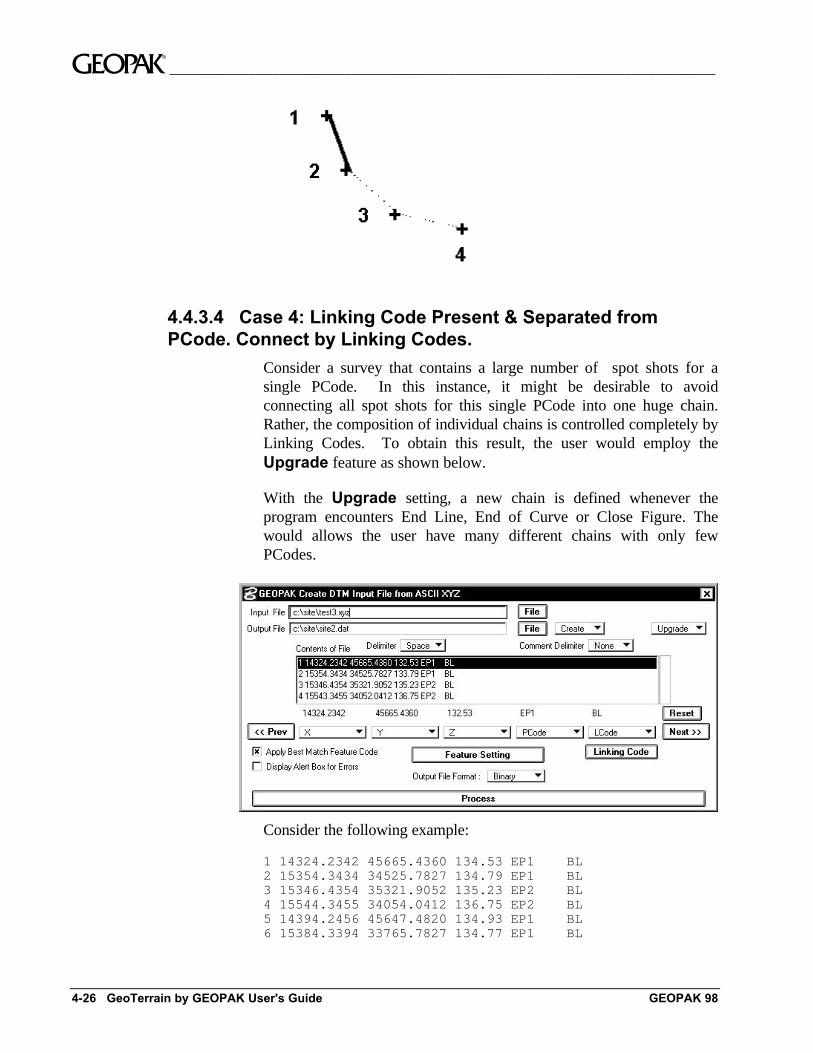
4.4.3.4 Case 4: Linking Code Present & Separated fromPCode. Connect by Linking Codes.
Consider a survey that contains a large number of spot shots for asingle PCode. In this instance, it might be desirable to avoidconnecting all spot shots for this single PCode into one huge chain.Rather, the composition of individual chains is controlled completely byLinking Codes. To obtain this result, the user would employ theUpgrade feature as shown below.
With the Upgrade setting, a new chain is defined whenever theprogram encounters End Line, End of Curve or Close Figure. Thewould allows the user have many different chains with only fewPCodes.
Consider the following example:
1 14324.2342 45665.4360 134.53 EP1 BL2 15354.3434 34525.7827 134.79 EP1 BL3 15346.4354 35321.9052 135.23 EP2 BL4 15544.3455 34054.0412 136.75 EP2 BL5 14394.2456 45647.4820 134.93 EP1 BL6 15384.3394 33765.7827 134.77 EP1 BL
__________________________________________________________________________________________ ~
GEOPAK 98 Extract Tools 4-27
This data would group together points with the same PCode name.Hence, when a terminating Linking Code is encountered, the name ofthe chain is upgraded as depicted below:
• Chain EP1-1 containing points 1 & 2; extract with EP1.
• Chain EP1-2 containing points 5 & 6; extract with EP1.
• Chain EP2-1 containing points 3 & 4; extract with EP4.
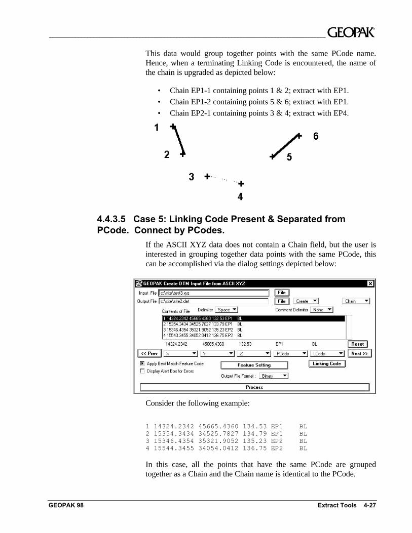
4.4.3.5 Case 5: Linking Code Present & Separated fromPCode. Connect by PCodes.
If the ASCII XYZ data does not contain a Chain field, but the user isinterested in grouping together data points with the same PCode, thiscan be accomplished via the dialog settings depicted below:
Consider the following example:
1 14324.2342 45665.4360 134.53 EP1 BL2 15354.3434 34525.7827 134.79 EP1 BL3 15346.4354 35321.9052 135.23 EP2 BL4 15544.3455 34054.0412 136.75 EP2 BL
In this case, all the points that have the same PCode are groupedtogether as a Chain and the Chain name is identical to the PCode.
~__________________________________________________________________________________________
4-28 GeoTerrain by GEOPAK User's Guide GEOPAK 98
The resultant chains include:
• Chain extracted containing points 1 & 4.
• Chain extracted containing points 3 & 4.
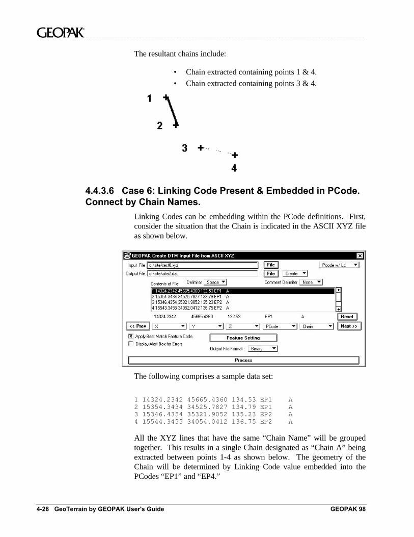
4.4.3.6 Case 6: Linking Code Present & Embedded in PCode.Connect by Chain Names.
Linking Codes can be embedding within the PCode definitions. First,consider the situation that the Chain is indicated in the ASCII XYZ fileas shown below.
The following comprises a sample data set:
1 14324.2342 45665.4360 134.53 EP1 A2 15354.3434 34525.7827 134.79 EP1 A3 15346.4354 35321.9052 135.23 EP2 A4 15544.3455 34054.0412 136.75 EP2 A
All the XYZ lines that have the same “Chain Name” will be groupedtogether. This results in a single Chain designated as “Chain A” beingextracted between points 1-4 as shown below. The geometry of theChain will be determined by Linking Code value embedded into thePCodes “EP1” and “EP4.”
__________________________________________________________________________________________ ~
GEOPAK 98 Extract Tools 4-29
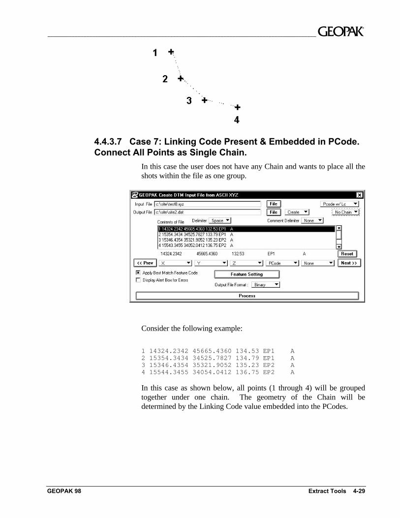
4.4.3.7 Case 7: Linking Code Present & Embedded in PCode.Connect All Points as Single Chain.
In this case the user does not have any Chain and wants to place all theshots within the file as one group.
Consider the following example:
1 14324.2342 45665.4360 134.53 EP1 A2 15354.3434 34525.7827 134.79 EP1 A3 15346.4354 35321.9052 135.23 EP2 A4 15544.3455 34054.0412 136.75 EP2 A
In this case as shown below, all points (1 through 4) will be groupedtogether under one chain. The geometry of the Chain will bedetermined by the Linking Code value embedded into the PCodes.
~__________________________________________________________________________________________
4-30 GeoTerrain by GEOPAK User's Guide GEOPAK 98
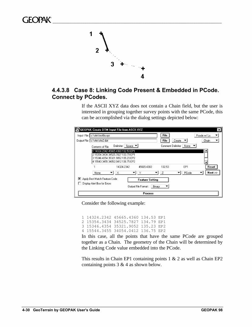
4.4.3.8 Case 8: Linking Code Present & Embedded in PCode.Connect by PCodes.
If the ASCII XYZ data does not contain a Chain field, but the user isinterested in grouping together survey points with the same PCode, thiscan be accomplished via the dialog settings depicted below:
Consider the following example:
1 14324.2342 45665.4360 134.53 EP12 15354.3434 34525.7827 134.79 EP13 15346.4354 35321.9052 135.23 EP24 15544.3455 34054.0412 136.75 EP2
In this case, all the points that have the same PCode are groupedtogether as a Chain. The geometry of the Chain will be determined bythe Linking Code value embedded into the PCode.
This results in Chain EP1 containing points 1 & 2 as well as Chain EP2containing points 3 & 4 as shown below.
__________________________________________________________________________________________ ~
GEOPAK 98 Extract Tools 4-31
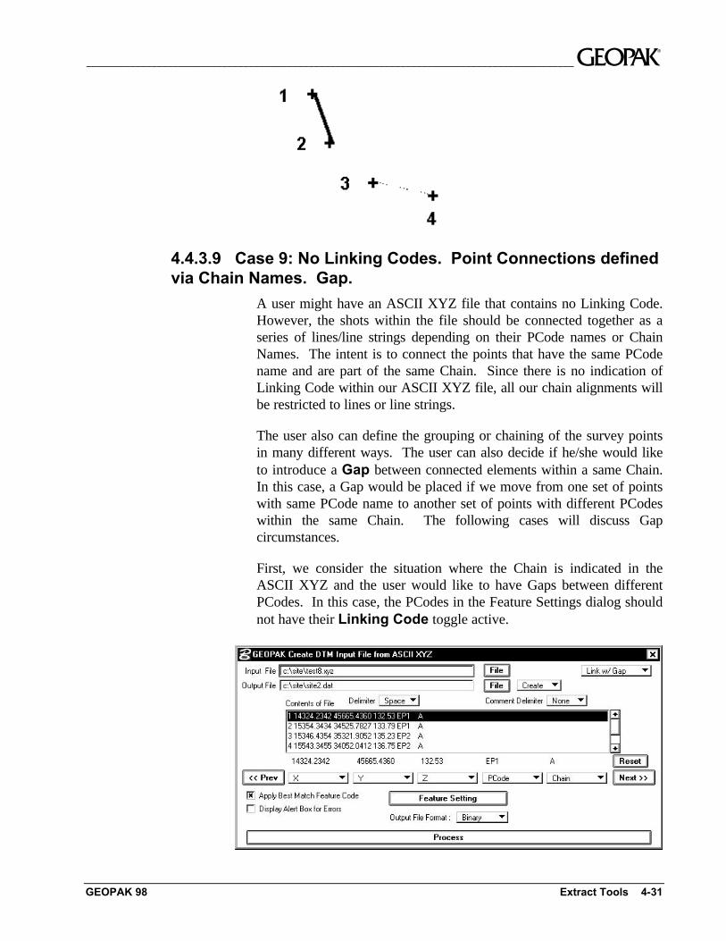
4.4.3.9 Case 9: No Linking Codes. Point Connections definedvia Chain Names. Gap.
A user might have an ASCII XYZ file that contains no Linking Code.However, the shots within the file should be connected together as aseries of lines/line strings depending on their PCode names or ChainNames. The intent is to connect the points that have the same PCodename and are part of the same Chain. Since there is no indication ofLinking Code within our ASCII XYZ file, all our chain alignments willbe restricted to lines or line strings.
The user also can define the grouping or chaining of the survey pointsin many different ways. The user can also decide if he/she would liketo introduce a Gap between connected elements within a same Chain.In this case, a Gap would be placed if we move from one set of pointswith same PCode name to another set of points with different PCodeswithin the same Chain. The following cases will discuss Gapcircumstances.
First, we consider the situation where the Chain is indicated in theASCII XYZ and the user would like to have Gaps between differentPCodes. In this case, the PCodes in the Feature Settings dialog shouldnot have their Linking Code toggle active.
~__________________________________________________________________________________________
4-32 GeoTerrain by GEOPAK User's Guide GEOPAK 98
Consider the following example:
1 14324.2342 45665.4360 134.53 EP1 A2 15354.3434 34525.7827 134.79 EP1 A3 15346.4354 35321.9052 135.23 EP2 A4 15544.3455 34054.0412 136.75 EP2 A
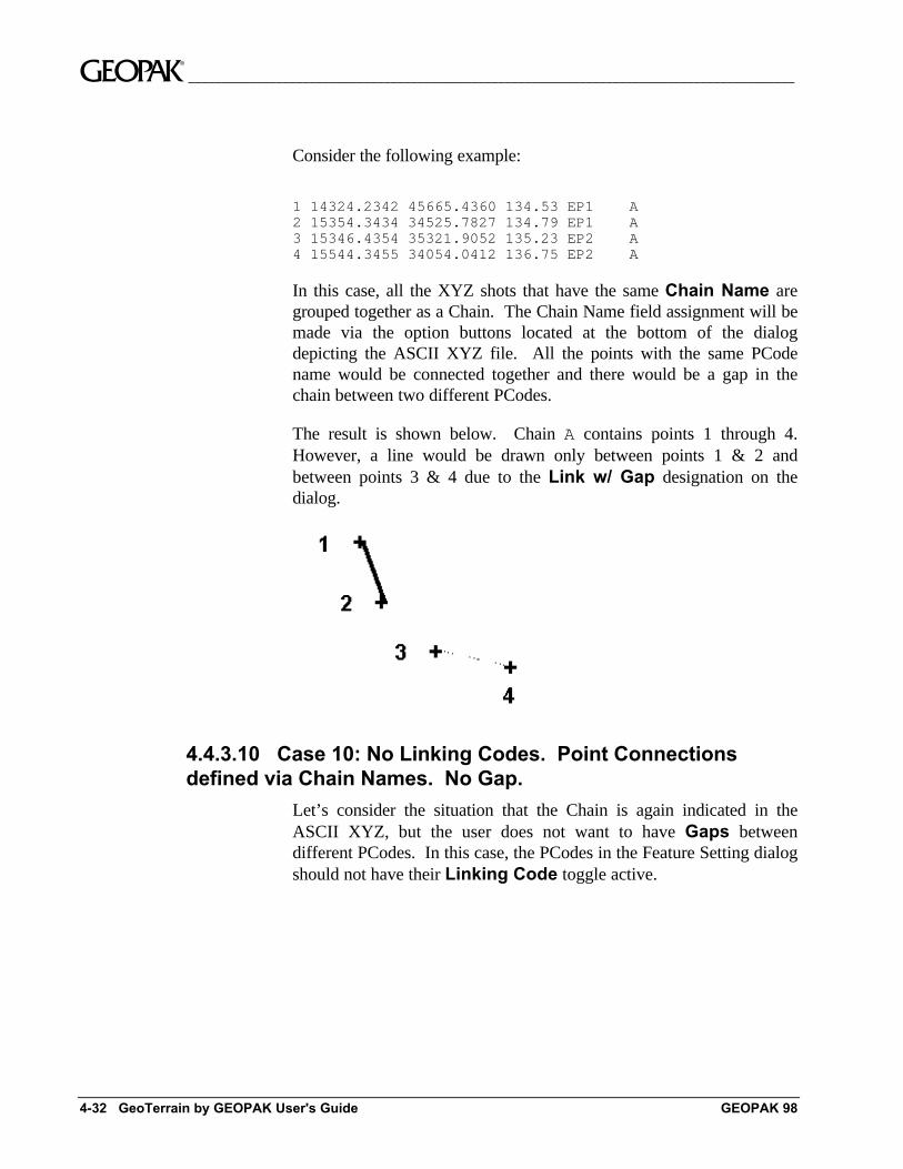
In this case, all the XYZ shots that have the same Chain Name aregrouped together as a Chain. The Chain Name field assignment will bemade via the option buttons located at the bottom of the dialogdepicting the ASCII XYZ file. All the points with the same PCodename would be connected together and there would be a gap in thechain between two different PCodes.
The result is shown below. Chain A contains points 1 through 4.However, a line would be drawn only between points 1 & 2 andbetween points 3 & 4 due to the Link w/ Gap designation on thedialog.
4.4.3.10 Case 10: No Linking Codes. Point Connectionsdefined via Chain Names. No Gap.
Let’s consider the situation that the Chain is again indicated in theASCII XYZ, but the user does not want to have Gaps betweendifferent PCodes. In this case, the PCodes in the Feature Setting dialogshould not have their Linking Code toggle active.
__________________________________________________________________________________________ ~
GEOPAK 98 Extract Tools 4-33
Consider the following example:
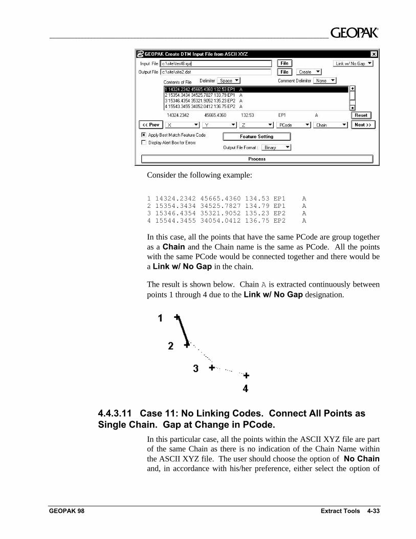
1 14324.2342 45665.4360 134.53 EP1 A2 15354.3434 34525.7827 134.79 EP1 A3 15346.4354 35321.9052 135.23 EP2 A4 15544.3455 34054.0412 136.75 EP2 A
In this case, all the points that have the same PCode are group togetheras a Chain and the Chain name is the same as PCode. All the pointswith the same PCode would be connected together and there would bea Link w/ No Gap in the chain.
The result is shown below. Chain A is extracted continuously betweenpoints 1 through 4 due to the Link w/ No Gap designation.
4.4.3.11 Case 11: No Linking Codes. Connect All Points asSingle Chain. Gap at Change in PCode.
In this particular case, all the points within the ASCII XYZ file are partof the same Chain as there is no indication of the Chain Name withinthe ASCII XYZ file. The user should choose the option of No Chainand, in accordance with his/her preference, either select the option of
~__________________________________________________________________________________________
4-34 GeoTerrain by GEOPAK User's Guide GEOPAK 98
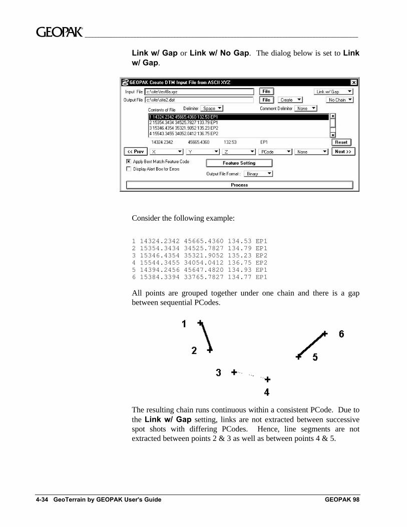
Link w/ Gap or Link w/ No Gap. The dialog below is set to Linkw/ Gap.
Consider the following example:
1 14324.2342 45665.4360 134.53 EP12 15354.3434 34525.7827 134.79 EP13 15346.4354 35321.9052 135.23 EP24 15544.3455 34054.0412 136.75 EP25 14394.2456 45647.4820 134.93 EP16 15384.3394 33765.7827 134.77 EP1
All points are grouped together under one chain and there is a gapbetween sequential PCodes.
The resulting chain runs continuous within a consistent PCode. Due tothe Link w/ Gap setting, links are not extracted between successivespot shots with differing PCodes. Hence, line segments are notextracted between points 2 & 3 as well as between points 4 & 5.
__________________________________________________________________________________________ ~
GEOPAK 98 Extract Tools 4-35
4.4.3.12 Case 12: No Linking Codes. Connect All Points asSingle Chain. No Gap at Change in PCode.
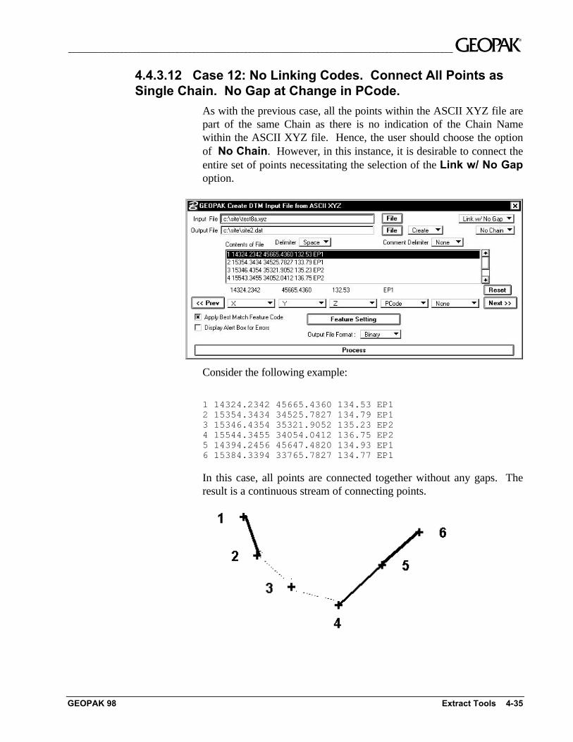
As with the previous case, all the points within the ASCII XYZ file arepart of the same Chain as there is no indication of the Chain Namewithin the ASCII XYZ file. Hence, the user should choose the optionof No Chain. However, in this instance, it is desirable to connect theentire set of points necessitating the selection of the Link w/ No Gapoption.
Consider the following example:
1 14324.2342 45665.4360 134.53 EP12 15354.3434 34525.7827 134.79 EP13 15346.4354 35321.9052 135.23 EP24 15544.3455 34054.0412 136.75 EP25 14394.2456 45647.4820 134.93 EP16 15384.3394 33765.7827 134.77 EP1
In this case, all points are connected together without any gaps. Theresult is a continuous stream of connecting points.
~__________________________________________________________________________________________
4-36 GeoTerrain by GEOPAK User's Guide GEOPAK 98
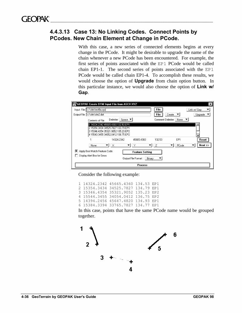
4.4.3.13 Case 13: No Linking Codes. Connect Points byPCodes. New Chain Element at Change in PCode.
With this case, a new series of connected elements begins at everychange in the PCode. It might be desirable to upgrade the name of thechain whenever a new PCode has been encountered. For example, thefirst series of points associated with the EP1 PCode would be calledchain EP1-1. The second series of points associated with the EP1PCode would be called chain EP1-4. To accomplish these results, wewould choose the option of Upgrade from chain option button. Inthis particular instance, we would also choose the option of Link w/Gap.
Consider the following example:
1 14324.2342 45665.4360 134.53 EP12 15354.3434 34525.7827 134.79 EP13 15346.4354 35321.9052 135.23 EP24 15544.3455 34054.0412 136.75 EP25 14394.2456 45647.4820 134.93 EP16 15384.3394 33765.7827 134.77 EP1
In this case, points that have the same PCode name would be groupedtogether.
__________________________________________________________________________________________ ~
GEOPAK 98 Extract Tools 4-37
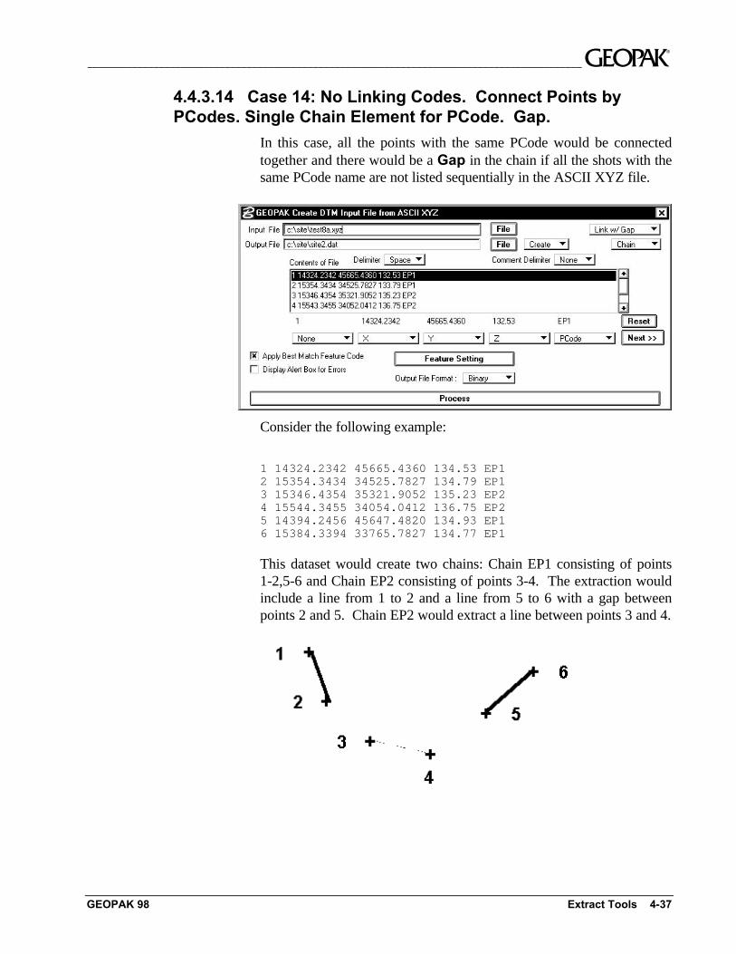
4.4.3.14 Case 14: No Linking Codes. Connect Points byPCodes. Single Chain Element for PCode. Gap.
In this case, all the points with the same PCode would be connectedtogether and there would be a Gap in the chain if all the shots with thesame PCode name are not listed sequentially in the ASCII XYZ file.
Consider the following example:
1 14324.2342 45665.4360 134.53 EP12 15354.3434 34525.7827 134.79 EP13 15346.4354 35321.9052 135.23 EP24 15544.3455 34054.0412 136.75 EP25 14394.2456 45647.4820 134.93 EP16 15384.3394 33765.7827 134.77 EP1
This dataset would create two chains: Chain EP1 consisting of points1-2,5-6 and Chain EP2 consisting of points 3-4. The extraction wouldinclude a line from 1 to 2 and a line from 5 to 6 with a gap betweenpoints 2 and 5. Chain EP2 would extract a line between points 3 and 4.
~__________________________________________________________________________________________
4-38 GeoTerrain by GEOPAK User's Guide GEOPAK 98
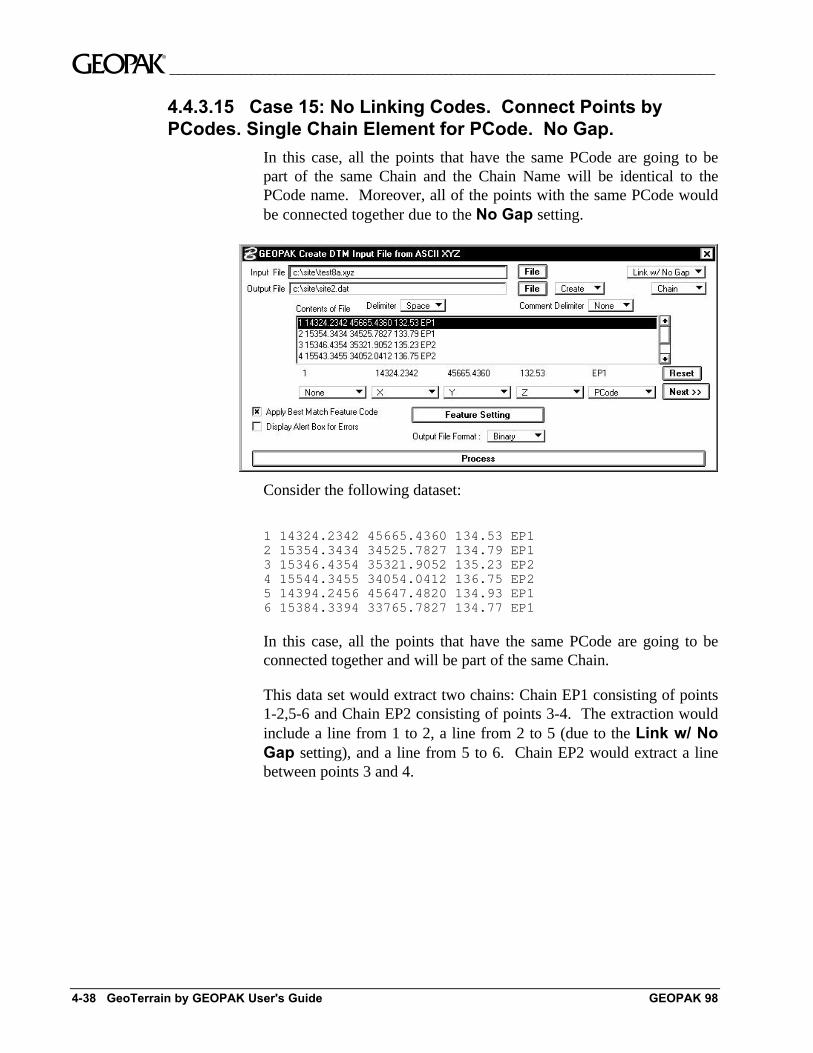
4.4.3.15 Case 15: No Linking Codes. Connect Points byPCodes. Single Chain Element for PCode. No Gap.
In this case, all the points that have the same PCode are going to bepart of the same Chain and the Chain Name will be identical to thePCode name. Moreover, all of the points with the same PCode wouldbe connected together due to the No Gap setting.
Consider the following dataset:
1 14324.2342 45665.4360 134.53 EP12 15354.3434 34525.7827 134.79 EP13 15346.4354 35321.9052 135.23 EP24 15544.3455 34054.0412 136.75 EP25 14394.2456 45647.4820 134.93 EP16 15384.3394 33765.7827 134.77 EP1
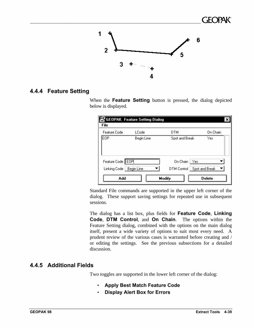
In this case, all the points that have the same PCode are going to beconnected together and will be part of the same Chain.
This data set would extract two chains: Chain EP1 consisting of points1-2,5-6 and Chain EP2 consisting of points 3-4. The extraction wouldinclude a line from 1 to 2, a line from 2 to 5 (due to the Link w/ NoGap setting), and a line from 5 to 6. Chain EP2 would extract a linebetween points 3 and 4.
__________________________________________________________________________________________ ~
GEOPAK 98 Extract Tools 4-39
4.4.4 Feature Setting
When the Feature Setting button is pressed, the dialog depictedbelow is displayed.
Standard File commands are supported in the upper left corner of thedialog. These support saving settings for repeated use in subsequentsessions.
The dialog has a list box, plus fields for Feature Code, LinkingCode, DTM Control, and On Chain. The options within theFeature Setting dialog, combined with the options on the main dialogitself, present a wide variety of options to suit most every need. Aprudent review of the various cases is warranted before creating and /or editing the settings. See the previous subsections for a detaileddiscussion.
4.4.5 Additional Fields
Two toggles are supported in the lower left corner of the dialog:
• Apply Best Match Feature Code• Display Alert Box for Errors
~__________________________________________________________________________________________
4-40 GeoTerrain by GEOPAK User's Guide GEOPAK 98
When the Apply Best Match Feature Code toggle is active, thebest match feature from the Feature Settings dialog is utilized. Thisoption allows placement of one feature in the Feature Settings dialogper item and locates derivatives of that feature in the field. Forexample, assume that feature 3001 is the EP for Edge of Pavement, butin the field, three different EP’s need to be located and chainedtogether. The different EP chains can be located as 30011, 30012 and30014. During the mapping process, these features will be matched tothe EP feature 3001 in the database. Therefore, the user does not haveto define multiple EP features in the database.
During processing, if impossible extraction or geometrics areattempted, an error message is displayed on the screen if the DisplayAlert Box for Errors toggle is activated. The error information isalways written to the Error Report regardless of the status of thistoggle.
Another field in the lower center of the dialog is the Output FileFormat: Binary or ASCII. Although binary files process faster,there is no other functional difference. The ASCII file can be reviewedvia any text editor, while a binary file may not.
To commence processing, press the Process bar at the bottom of thedialog. The result of this processing is a GEOPAK DAT file, whichsubsequently can be utilized to generate a DTM with the BuildTriangles tool.
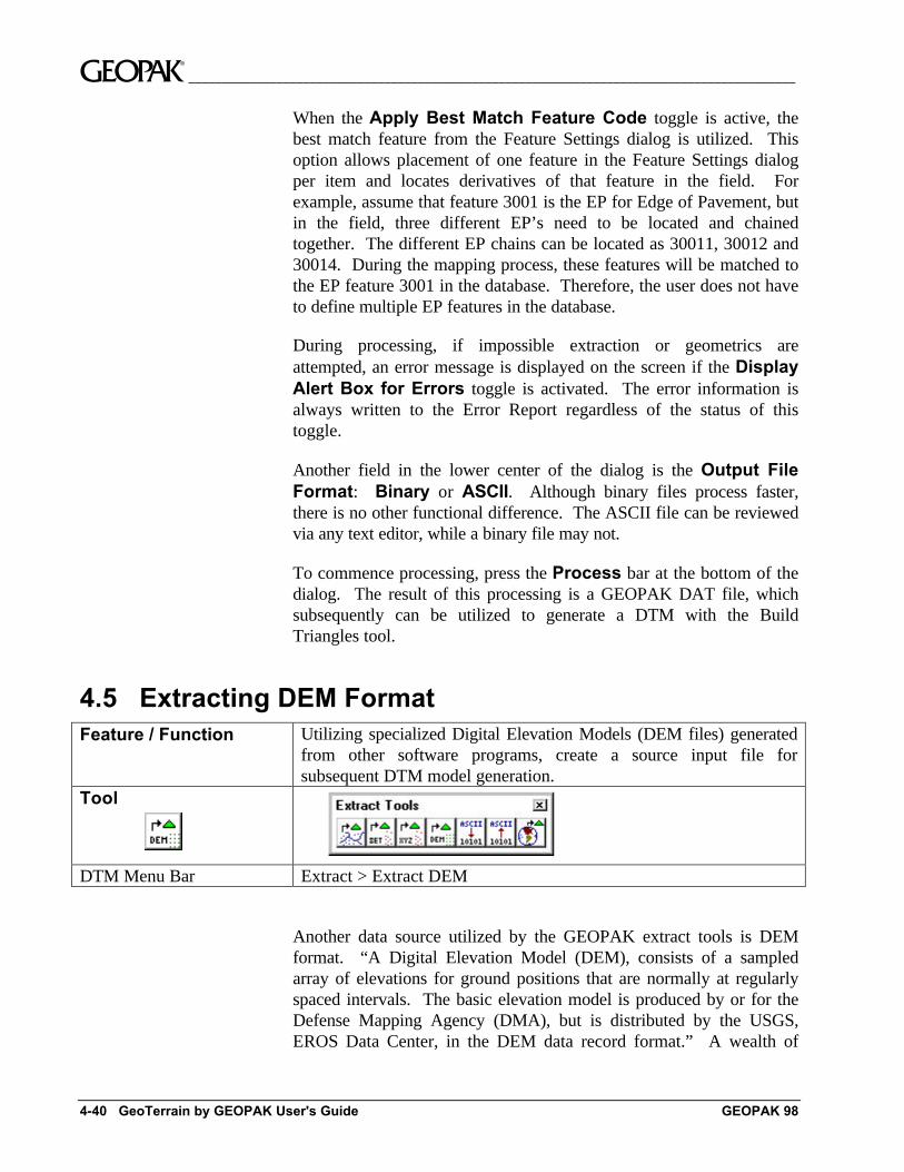
4.5 Extracting DEM FormatFeature / Function Utilizing specialized Digital Elevation Models (DEM files) generated
from other software programs, create a source input file forsubsequent DTM model generation.
Tool
DTM Menu Bar Extract > Extract DEM
Another data source utilized by the GEOPAK extract tools is DEMformat. “A Digital Elevation Model (DEM), consists of a sampledarray of elevations for ground positions that are normally at regularlyspaced intervals. The basic elevation model is produced by or for theDefense Mapping Agency (DMA), but is distributed by the USGS,EROS Data Center, in the DEM data record format.” A wealth of
__________________________________________________________________________________________ ~
GEOPAK 98 Extract Tools 4-41
information on DEM formatted data can be obtained fromwww.usgs.gov. Access the Mapping option.
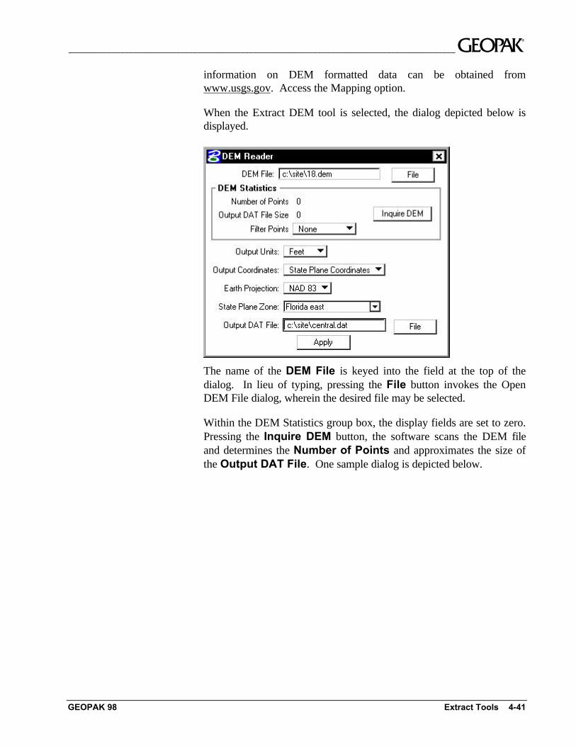
When the Extract DEM tool is selected, the dialog depicted below isdisplayed.
The name of the DEM File is keyed into the field at the top of thedialog. In lieu of typing, pressing the File button invokes the OpenDEM File dialog, wherein the desired file may be selected.
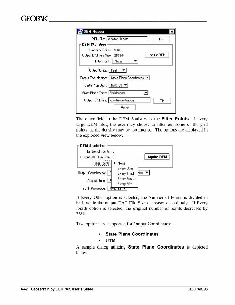
Within the DEM Statistics group box, the display fields are set to zero.Pressing the Inquire DEM button, the software scans the DEM fileand determines the Number of Points and approximates the size ofthe Output DAT File. One sample dialog is depicted below.
~__________________________________________________________________________________________
4-42 GeoTerrain by GEOPAK User's Guide GEOPAK 98
The other field in the DEM Statistics is the Filter Points. In verylarge DEM files, the user may choose to filter out some of the gridpoints, as the density may be too intense. The options are displayed inthe exploded view below.
If Every Other option is selected, the Number of Points is divided inhalf, while the output DAT File Size decreases accordingly. If Everyfourth option is selected, the original number of points decreases by25%.
Two options are supported for Output Coordinates:
• State Plane Coordinates• UTM
A sample dialog utilizing State Plane Coordinates is depictedbelow.
__________________________________________________________________________________________ ~
GEOPAK 98 Extract Tools 4-43
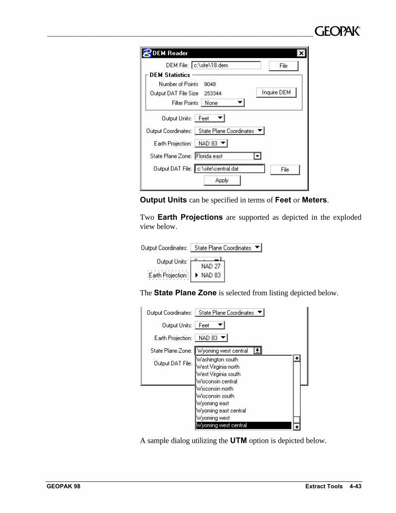
Output Units can be specified in terms of Feet or Meters.
Two Earth Projections are supported as depicted in the explodedview below.
The State Plane Zone is selected from listing depicted below.
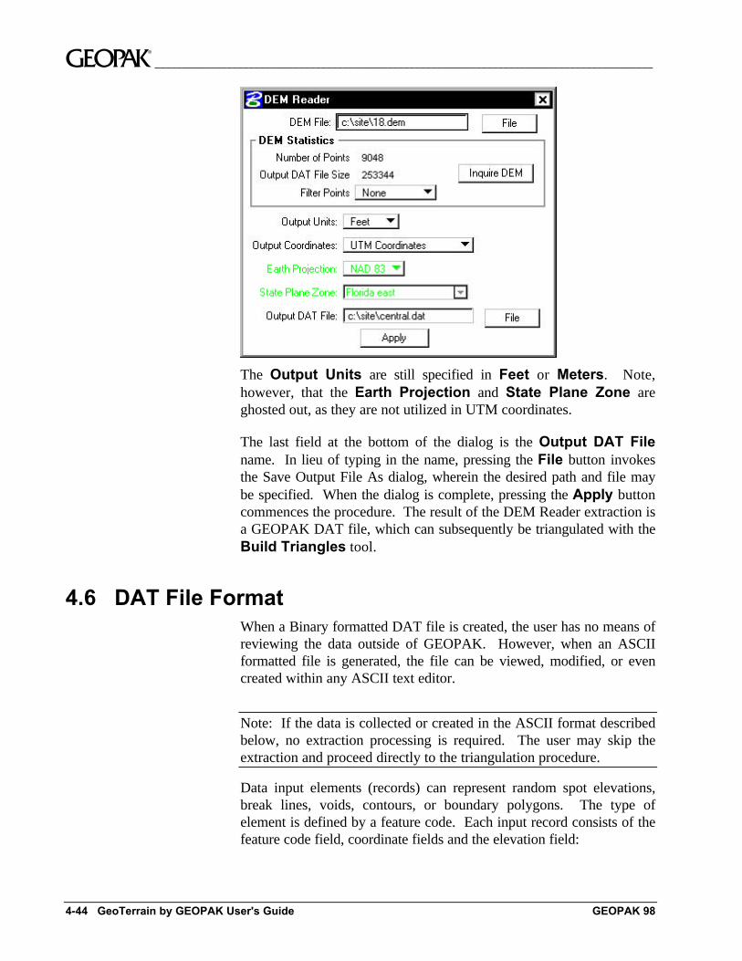
A sample dialog utilizing the UTM option is depicted below.
~__________________________________________________________________________________________
4-44 GeoTerrain by GEOPAK User's Guide GEOPAK 98
The Output Units are still specified in Feet or Meters. Note,however, that the Earth Projection and State Plane Zone areghosted out, as they are not utilized in UTM coordinates.
The last field at the bottom of the dialog is the Output DAT Filename. In lieu of typing in the name, pressing the File button invokesthe Save Output File As dialog, wherein the desired path and file maybe specified. When the dialog is complete, pressing the Apply buttoncommences the procedure. The result of the DEM Reader extraction isa GEOPAK DAT file, which can subsequently be triangulated with theBuild Triangles tool.
4.6 DAT File FormatWhen a Binary formatted DAT file is created, the user has no means ofreviewing the data outside of GEOPAK. However, when an ASCIIformatted file is generated, the file can be viewed, modified, or evencreated within any ASCII text editor.
Note: If the data is collected or created in the ASCII format describedbelow, no extraction processing is required. The user may skip theextraction and proceed directly to the triangulation procedure.
Data input elements (records) can represent random spot elevations,break lines, voids, contours, or boundary polygons. The type ofelement is defined by a feature code. Each input record consists of thefeature code field, coordinate fields and the elevation field:
__________________________________________________________________________________________ ~
GEOPAK 98 Extract Tools 4-45
• Feature Code (integer value)• X Coordinate (decimal value)• Y Coordinate (decimal value)• Elevation (decimal value)
A sample fragment from the ASCII input file is shown below:
• 1 17381.651 22324.071 391.600
• 1 17383.071 21997.581 332.850
• 2 17404.721 21621.311 440.890
• 3 17405.041 22319.311 382.380
• 3 17427.411 21907.411 297.200
The format in the file is quite simple: a feature code followed by X, Yand Z coordinate values in succession. A single point record occupieseach line of the ASCII file. Spaces serve as delimiters betweenindividual fields.
The feature code is mandatory and informs GEOPAK how to interpretthe input records. The following are valid feature code values andassociated descriptions.
Feature Code Function
1 Random Spots
2 Start of Break Line
3 Subsequent Point(s) on a Break Line
4 Boundary Polygon Point
5 Start of Contour Line
6 Subsequent Point(s) on a Contour Line
7 Start of a Void
8 Subsequent Point(s) of aVoid
9 Start of an Island
10 Subsequent Point(s) of an Island
13 Start of a Graphic Triangles
14 Subsequent Point(s) of a Triangle
15 Start of a Drape Void
16 Subsequent Point(s) of a Drape Void
~__________________________________________________________________________________________
4-46 GeoTerrain by GEOPAK User's Guide GEOPAK 98
Random Spots are points that have no functional relationship to anyother point. Random survey shots in open terrain would be an exampleof random spots.
Break Lines designate linear features such as edges of pavement,ditch bottom, ridges or valleys. The first point in a series of connectedbreak lines has a feature assignment of "2." The second and subsequentpoints along the break line have a feature code of "3." Break line datamust be continuous within the data file.
A Void delineates an area of no data or obscured area and is defined ina series of points forming a closed element. The elevations of the voidare incorporated into the data file. In addition, the void must becontiguous within the data file.
A Boundary Polygon is used to constrain the external boundary of thetriangulated model. All points along the boundary polygon areassigned a feature code of "4." A boundary polygon must start andfinish with the same point. In addition, the boundary polygon must becontinuous within the data file.
A Drape Void delineates an area of no data or obscured area and isdefined in a series of points forming a closed element. It differs from aVoid in that the elevations of the void elements are not incorporatedinto the data file. Rather, the void elements are draped onto the model,and model elevations are utilized. The void must be contiguous withinthe data file.
An Island is a closed element completely encompassed within a Void.Random spots, breaks and contour elements may be present within theisland.
Graphic Triangles are 3D triangles placed at true elevations.
Since GEOPAK ignores any additional fields past the fourth field (ZCoordinate), extraneous data such as comments or point codeinformation can be included in the data file for reference or use withother software or GEOPAK components.
__________________________________________________________________________________________ ~
GEOPAK 98 Extract Tools 4-47
4.7 Conversion ProcessesFeature / Function Utilizing a previously created ASCII DAT file, convert an ASCII
DAT file to Binary or apreviously created ASCII DAT file, convertfrom ASCII to Binary.
Tool
DTM Menu Bar Utilities > ASCII to BinaryUtilities > Binary to ASCII
Two conversion processes for DTM Input files (*.dat) are supported.These conversions include:
• ASCII to Binary
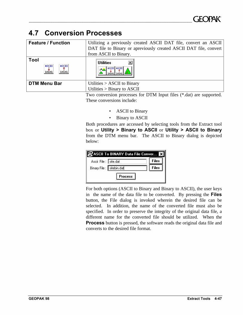
• Binary to ASCIIBoth procedures are accessed by selecting tools from the Extract toolbox or Utility > Binary to ASCII or Utility > ASCII to Binaryfrom the DTM menu bar. The ASCII to Binary dialog is depictedbelow:
For both options (ASCII to Binary and Binary to ASCII), the user keysin the name of the data file to be converted. By pressing the Filesbutton, the File dialog is invoked wherein the desired file can beselected. In addition, the name of the converted file must also bespecified. In order to preserve the integrity of the original data file, adifferent name for the converted file should be utilized. When theProcess button is pressed, the software reads the original data file andconverts to the desired file format.