Embed Size (px)
Citation preview
SECTION D
Cadillac 355 V-8
Supplementary
Sales Data
Presentation Outline Sales Data
EXTERNAL APPEARANCE STORY
Side View
Hood, Cowl
Fenders and Running Boards.. . .
Head-on-View
Large quarter windows. Small overhang of body.
Well proportioned. Hoods have door ports. Leather corner pads on hood.
18-gauge metal. Wire reinforced in rolled edge. Stainless steel moulding. Fender shelf one-piece construction.
lOM-inch lens. Chromium supports. Unusually strong. Bumper brackets integral with frame.
COMFORT—THE PASSENGER STORY C o m f o r t
Rear Door
Head Room
Upholstery
Door width, 293¾ inches. Opening and closing action cushioned b> spring in door check.
Height, 49 inches (from floor).
Seven optional cloths—three Broadcloths, two Mohairs, two Whipcords. Shoulder support—seat back 21 inches high.
Ample space for baggage if required. Quarter lights for convenience and comfort a t night.
.Strong and durable. Ternstedt make. All doors can be locked.
All Sedan and Coupe bodies wired for radio installation.
145
mmmmmm
Presentation Outline Sales Data
T H E OWNER-DRIVER STORY F r o n t S e a t
Door
Adjustment
Comfort
Vision Steering Wheel
Steering Type
Con t ro l s Instrument Board . .
1 gnition—Trans-
Width 36¾ inches. Front seat frame covered with upholstery. No exposed metal. 4 inches maximum adjustment. Shoulder support—seat back 21 inches high. Unobstructed by left middle pillar. 18 inches diameter. Moulded Bake-lite wheel with steel core prevents splintering. Hourglass type worm provides more contact surface with sector.
Well lighted bv 2 lights. Oil gauge pressure 30 lbs. a t 30 M. P . H . Shutters open a t 155 degrees. Full open a t 180 degrees.
Seven-degree angle. Glass channels chrome plated. Greater safety with wiping of entire windshield for bad weather driving.
Turning off ignition automatically locks car.
EXTERNAL FEATURES STORY
Wheel base
Turning R a d i u s . . . .
Whee l s
134 inches.
23 feet 10 inches (right and left). Over-all length (fender wells) 202 f i inches. Over-all length of car with rear tirecarrier (Sedans) 203 }f inches.
set under hydraulic pressure. Lateral lacing of spokes in wire wheels provides greater strength.
146
Presentation Outline Sales Data
E X T E R N A L F E A T U R E S STORY'—Conl.
Optional Equipment
Ball Bearings.
Tires
S p r i n g s Construction. . . .
Sizes: (a) Front
(b) Rear
L u b r i c a t i o n . . . . . .
Covers
Spring Shackles. .
D u o d r a u l i c S h o c k Absorbers
Adjustments
Lubrication.
5-wheel. Wire % . Demountable wood $ . Disc $ 6-wheel (including fender wells, 2 spare tires and trunk rack). Wire $ .Demountable wood$ Disc $ . Tires in fender wells supported by frame bracket do not chafe from rubbing against metal.
Make—New Departure.
Size wood wheels standard 6.50 x 19. Demountable wood or wire or disc 7.00 x 18. Optional tires—United States, Firestone and Goodyear. Pressure 40 lbs. rear, 45 lbs. front. No extra charge for larger tires on optional wheel equipment.
Silico-Manganese steel. Semiellip-tical (rolled point).
9 leaves38"x 2" i ,T , , „ > Underslung.
11 leaves 58" x 2 ' J
Graphite and grease lubricant used in metal covers. Alemite system for shackles.
Metal with spring clips on rear springs.
Compression type.
Varying sizes of metering pins.
Alemite nipples.
147
Presentation Outline Sales Data
EXTERNAL FEATURES STORY— Cont, Frame
Strength.
Cross Members.
Size—Depth 8 inches; thickness ^ inches; pressed carbon steel; width top flange 3 inches; bottom flange 2 ¾ inches.
Seven.
FISHER BODY STORY Wood a n d Steel
Strength
Preparation.
Body Frames
Panel ing
Body Features Roof
Doors
Body Mounting.
Safety Glass Construction
Ability Manufactur ing Control
After milling, wood seasons for three months. Then it is kiln dried to 5 per cent moisture content and cut to size. Curved pieces are cut, notsteam bent. After cutting, pieces are again stored for seasoning. (Steam bent process allows wood to warp, lose shape.)
Assembled separately from body.
Resist weaving.
Anti-squeak, nonhardening paste is used.
Center layer of pyroxalin is coaled with cementing substance (cellulose acetate) and two pieces of heavy plate glass are pressed to either side under a pressure of 360 lbs. per square inch.
148
Presentation Outline Sales Data
GENERAL MOTORS STORY
General Motors leadership a n d affiliation helps Cadillac Purchas ing E c o n o m y Means Added Value
Value of Research Accomplishments...
Proving Ground
Parts Qual i ty Control
GMAC Rates
Valve silencer, 2-plane crankshaft, vacuum assister brake, intake muffler, Duco, ethyl compound, harmonic balancer.
A yardstick to measure all cars, even foreign makes and competitors.
1245 acres.
Such firms as Harrison Radiator Corp., A. C . Spark Plug, Delco Products, Delco-Remy Corp., Hyatt Bearings Div., New Departure Mfg. Company, etc.
Uniform and national service through United Motors.
Lower rates than other companies.
149
Presentation Outline Sales Data
GENERAL MOTORS STORY—Cont.
Summary
Being a unit of General Motors it Las a friendly interest in dealer and purchaser.
Mechanical Features T H E V-tt E N G I N E STORY
E n g i n e I m p r o v e m e n Is
Model and Serial No
Engine Size.
Horsepower.
Gear Ratios Intake Mul l l e r . . . Strong Crankease.
R e a s o n s for S u p e r i o r i t y of V- type P r inc ip l e E n g i n e s
Torsional Vibration Cancelled
Model 355. Engine numbers start a t 8(1(1.()01. Bore 3s-jj inches, stroke i\% inches. Displacemen 1355 cubic inches. Compression 108 ll>s. a t 1000 R.P .M. Compression ratio 5.35 to 1. Optional 5.26 to 1. N.A.C.C. rating 36.45 actually develops more than 95 ll ' .P. a t 3000 R.P .M. Maximum R.P .M. about 4200. (Sizes) 4 to 1; 4.40 t o 1; 4.75 to 1. Resonance type. Silicon aluminum. Non-resonant. Heavily ribbed for strength and strong support to bearing bridges. Separate from engine block. Reduces service costs in case of accident. Lower half is pressed-steel oil pan. 5-point suspension.
Known also as twist, whip, crankshaft wind up.
150
Presentation Outline Sides Data
T H E V-8 ENGINE STORY— Cont.
Short Crankshaft.
Main Bearings.
Complete Engine Ventilation
E n g i n e P a r t s Connecting Rods.
Length 23s§- inches (outer ends of front to rear bearings). High carbon steel. Completely machined all over. Compensators bolted t o shaft and spot welded to insure rigidity. Weighs 68 lbs. 2 oz. Diameter 2?« inches.
Three main bearings. Babbitt-bronze backed. Clearance .001 inch to .0015 inch. Dimensions: Front , 1\\ inches by 2 3
s inches; center, \% inches by 2 ? s inches; rear, 2 ¾ inches by 2f , inches (combined length 63¾ inches). Rear bearing takes thrust . Bearing area 4 8 ¾ square inches. Replacement cost $39.85. Compares with $115.50 on Packard 8.
Positive ciroidation of air through crankcase lubricates valve springs in valve chamber. Compensators on crankshaft when turning act as air pump, drawing air through inlet breather a t side of left block and discharging it through two vent tubes one each at front of left block and rear of right block.
M a t e r i a l — D r o p - f o r g e d c h r o m e Molybdenum steel. Bearing material poured Babbit t . No shims used. Bearing clearance .001 to .0025. Rods can be removed through bottom of engine without taking off cylinder head. Diameter of rifle-drilled passage f i n c h e s . Set of 8 rods balanced within }s ounce each. Journal width and length Z% inches by l ? s inches. Length center to center 10¾ inches. Both ends diamond bored.
151
Presentation Outline Sales Data
T H E V-8 E N G I N E STORY— Cont.
Camshaft.
Pistons.
Cylinder Heads .
Cylinders
Morse chain drive from crankshaft. Chain 1 ¾ inches wide, 27 inches long. Material high- carbon steel forging. Drilled from end to end for oil passage. Four bearings: No. ] , 1 ¼ inches by I f f inches; No. 2, 2-H inches by 1 inch; No. 3, 2 $ | inches by l i s inches; No. 4, 1¾ inches by 1 { | inches. Weight 9 ½ lbs. Turns a t one half crankshaft speed. Distributor drive gear separate on shaft. Can be replaced without installing new camshaft.
Material—Close-grained nickel-iron piston. 3 times harder than aluminum. 3 compression rings above piston pin. 1 oil ring below pin. Lightweight—tapered skirt. Piston weight, without rings, pin or bushing, 24 ounces. Hand fitted to limits of .003 inches. Piston pin locked by set screw—in piston boss. Piston pin length 3yj inches, diameter J/g inch. Piston ring make—perfect circle. Pistons and rods each held to A-ounce limit in weight.
Cover plates protect wiring.
Cast en bloc of 4. Machined, reamed and honed to finish. Honing gives glasslike finish t o cylinder walls and adds life to pistons and rings. Blocks are staggered to permit use of side-by-side connecting rods. Crankcase cast separately from blocks. Blocks are interchangeable.
152
mm
Presentation Outline Sales Data
T H E V-8 E N G I N E STORY—Conl.
Manifolds Expansion joints a t front of motor.
E x h a u s t . . . . Porcelain finish. Two 4-port cast iron, Y connection.
Intake Two two-port cast-iron; diameter 1}'>$ inches.
Chains Morse. Timing chain drives camshaft from crankshaft. Generator and pump driven from crankshaft. Two chains distribute load, longer life. Adjustment of position of water pump and generator mounting takes up chain stretch.
Timing chain width 1¾ inches, length 27 inches.
Generator and pump chain width 1 f i n c h e s .
Valves 16 valves operated by single camshaft. Valve action through rollers on cam slide. Diameter valve lifter
' 1 ̂ f inches.
Inlet Inlet valve Tungsten. Diameter \14 inches (clear). Valve seat angle 30 degrees.
Exhaust . . . . Exhaust valve silichrome. Diameter 1 ½ inches (clear). Valve seat 45 degrees.
Valve lift H-inch valve guides—removable. Lubricated through ports in cylinder walls. Valve spring pressure open 160 lbs. Closed 79 lbs.
Valve springs retained by split tapered bushing and not by pin which is liable to shear off.
153
Presentation Outline Sales Data
COOLING SYSTEM
h gallons.
Impeller type. Connected to generator with laminated couplings. Safet y pin in shaft sheers off if pump is frozen, and protects chain. Location on outside of engine. Greater accessibility. Has positive nozzle action. Better design than agitator t y r e mounted in cylinder block. P u n p delivers 5880 gallons per hor r (41.000 lbs.) a t 3200 R. P . M. (98 gallons per minute).
Cylinder blocks interconnected by brass tubes cast integral with crank-case providing equal distribution of water. One drain plug on inlet elbow on the right-band cylinder block accessible from above. Water is changed approximately 1175 times per hour in engine at 65 M.P.H.. taking heat out, of engine quickly.
Make—Harrison cellular with copper core because it is an efficient conductor of heat and resists corrosion. Pressed steel casing is copper plated and polished, then nickel plated twice and polished, then chrome plated.
Built in. Opens 155 degrees to 165 degrees. Closes 175 degrees to 165 degrees.
Thermostat controlling shutters mounted in radiator in direct path of water flow from engine. Assist in quick warming up of engine in cold weather starting.
154
Presentation Outline Sales Data
C O O L I N G SYSTEM—Cord.
F a n .
Advantages of V-type Cadillac cooling over Straight-8 Design.
E n g i n e L u b r i c a t i o n Importance
Pressure Sys t em. . .
Filter and Screen. .
Regulator.
Gauge.
Own make—six blades—Diameter 21 inches. Automatically lubricated by oil pump in engine. Fan belt % inches wide, 91£ inches long, endless V-type design. Driven from pulley on crankshaft. Fan belt drives fan only. Belt adjustment by raising or lowering fan bracket.
6 advantages.
Determines life of car. Protects the precision of the parts .
Capacity, 8 quarts . Pressure by gear type oil pump. 8 quarts of oil pass through oil passage in 43 seconds a t 3000 R . P . M . Pump driven by lower end of distributor shaft from spiral gear on camshaft.
AC filter located on by-pass in oil line. No danger of stopping circulation to engine. Oil screen covers oil pan, strains oil returning from engine ; prevents sediment collection at pump.
Accessible location on outside a t front of engine. Oil flows over timing and water pump chains. Automatic pressure type. Valve opens a t 11 lbs. pressure approximately 10 M.P.H. Normal oil pressure 30 lbs. a t 30 M.P.H.
Float type. Positivereading. Located at rear of engine. Change oil every 2000 miles.
155
Presentation Outline Sales Data
System Lubricants.
CHASSIS LUBRICATION
Alemite—High pressure. Lubricant must reach bearing to accomplish purpose. 4 kinds are necessary and supplied in Cadillac: Engine Oil—Differential and Transmission Grease — Chassis Lubricant — Rear Axle Grease.
Pressure System...
Schedule and Charges
Manual Lubrication also necessary with automatic system...
Ordinary hand grease gun pressure 500 lbs. to square inch, higher pressure with service station equipment insures distribution of lubricant to bearing surface and expels dirt. Positive protection regardless of weather. So-called automatic systems use only low pressure in line, 45 lbs. and oil reaches bearing points through drip oilers. Some systems use capillary action only, caused by movement of car when in operation.
Cadillac standard lubrication schedule specifies visit to service station SO day periods (or every 1000 miles). Charge for positive lubrication of all points on car costs no more than partial service necessary with centralized systems.
No possible chance of forgetting universal joint lubrication on Cadillac.
Variable mileage periods when different parts need attention supplemented by necessity to remember daily operation of plunger makes so-called automatic systems less efficient when compared with (Cadillac standard lubrication service at same cost.
156
Presentation Outline Sales Data
Ignition Distributor.
ELECTRICAL SYSTEM Delco-Remy Two contact arms—4-lobe cam. Jump spark type. Firing order 1L; 4R; 4L; 2L: 3R; 3L; 2R: IR. A.C. Metric (18 m.m.) spark plugs. Wiring in insulated cable in metal conduits. Re-checking timing through hole in flywheel cover on transmission case.
Starter
Battery
Generator
Breaker
Spark Control
Ignition Lock.
Ratio between starter and flywheel 25 to 1 (approx.). Engine cranking speed 90-100 R.P.M. 120 amp. hour, 6-volt. Positive terminal grounded. 2-pole. 19 M.P.H. maximum normal charging speed. Thermostat opening temperature 175 degrees F. Positive chain driven instead of through fan belt. Short circuit indicated by buzzing. Nothing to replace. No fuses to use or replace. Automatic advance 28 degrees. Manual advance (on dash) 19 degrees. Greater protection against car theft than cars with only ignition switch.
Fuel Sys tem Tank Fuel Feed and Vacuum Pump.
FUEL SYSTEM
21-22 gallons.
Stewart - Warner vacuum tank. Driven by camshaft located at rear of engine. Assures engine adequate fuel supply regardless of speed or bill climbing.
157
]"reseutatiou Outline
C a r b u r e t o r Type
F U E L SYSTEM—Cont .
Features.
Plunger P u m p .
Intake Muffler.
Own make. Air valve single jet type. 2-inch throat. One adjustment.
Thermostatic control of vapor and air volumes. Thermostats in auxiliary air valve open a t 65 degrees to 85 degrees. 2 thermostats to relieve bowl pressures. First, opens a t 74 degrees to 78 degrees. Second, opens a t 125 degrees to 130 degrees.
To provide carburetor with extra gas for quick acceleration. Developed by General Motors R e search (see engine improvements).
C l u t c h Type .
Kelease.
Design.
T r a n s m i s s i o n D e s i g n . . . . . .
P O W E R TRANSMISSION SYSTEM
Plate type. Dry. Own make. 3 driving plates, 2 driven discs. Outside diameter 10 inches. Inside diameter 7 inches. Balanced statically and dynamically, 12 springs. Very light driven discs and hub, giving very little inertia, reduce the spinning action. No drag permits quick, smooth engagement.
Facings of woven asbestos material. Thickness .135 inch to .145 inch ( ^ inch). Clutch facing area 160 square inches.
Superiorities.
Syncro-Mesh 3 speeds forward, 1 reverse. Selective. Oil capacity, 3 quarts. Unit with power plant. Anybody who can drive can change gears without clashing. Less complicated than any 4-speed transmission.
158
Presentation Outline Sales Data
P O W E R T R A N S M I S S I O N SYSTEM—Cont .
Gear Reductions in Transmission. .
R e a r Axle ? 4 -Float ingType.
Torque Tube Drive
Bearings.
Universal J o i n t s . . .
Axle Shafts.
Ring Gears and Pinions
Tread . .
Rat ios .
Reverse 3.0 to I Low 2.5 to 1
Second 1.3 to 1 High 1.0 to 1
Cadillac make, .^-floating. Spiral bevel gears. Propeller shaft tubular, 2-inch diameter. Road clearance under center of rear axle 7 f | inches. Oil capacity 3 quarts .
Strong tube enclosing drive shaft-One universal joint only. Relieves springs of driving strains and stresses.
Two tapered roller in differential carrier. 2 ball in pinion shaft. 1 ball on each rear wheel.
X-type Spicer make. Only one is used. No worry about lubrication as on other cars.
1'1 s-inch diameter enclosed in strong housing with welded inner sleeve. Wheels mounted on bearings on outside of axle housing, taking load off axle shafts.
All pinions and ring gears are manufactured by Cadillac, matched and adjusted in final assembly in soundproof room.
59 Vi inches.
1 to 1; 4.40 to 1; 4.75 to 1.
159
Presentation Outline Sales Data
Brakes Design.
Self-centering Cains and Articulated Link
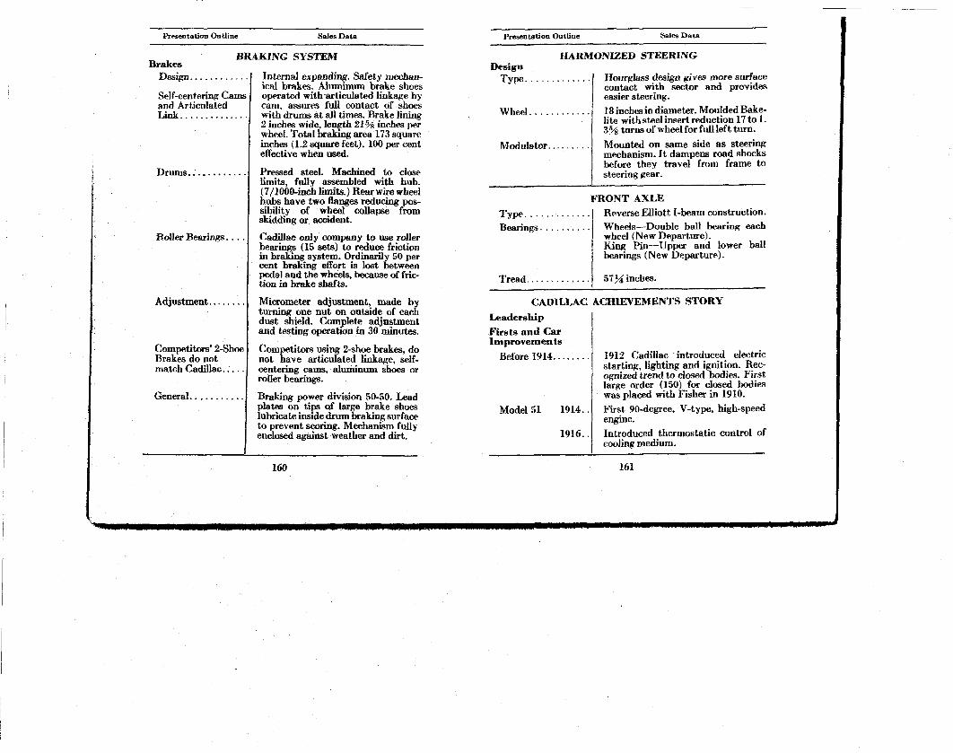
BRAKING SYSTEM
Internal expanding. Safety mechanical brakes. Aluminum brake shoes operated with articulated linkage by cam, assures full contact of shoes with drums at all times. Brake lining 2 inches wide, length 21¾ inches per wheel. Total braking area 173 square inches (1.2 square feet). 100 per cent effective when used.
Drums.
RoUer Bearings. .
Adjustment.
Competitors' 2-Shoe Brakes do not match Cadillac
General.
Pressed steel. Machined to close limits, fully assembled with hub. (7/1000-inch limits.) Rearwirewheel hubs have two flanges reducing possibility of wheel collapse from skidding or accident.
Cadillac only company to use roller bearings (15 sets) to reduce friction in braking system. Ordinarily 50 per cent braking effort is lost between pedal and the wheels, because of friction in brake shafts.
Micrometer adjustment, made by turning one nut on outside of each dust shield. Complete adjustment and testing operation in 30 minutes.
Competitors using 2-shoe brakes, do not have articulated linkage, self-centering cams, aluminum shoes or roller bearings.
Braking power division 50-50. Lead plates on tips of large brake shoes lubricate inside drum braking surface to prevent scoring. Mechanism fully enclosed against weather and dirt.
160
Presentation Outline Sales Data
Design Type.
Wheel.
HARMONIZED STEERING
Hourglass design gives more surface contact with sector and provides easier steering.
18 inches in diameter. Moulded Bake-lite with steel insert reduction 17 to 1. 3 ¾ turns of wheel for full left turn.
Modulator. Mounted on same side as steering mechanism. It dampens road shocks before they travel from frame to steering gear.
T y p e . . . Bearings.
FRONT AXLE Reverse Elliott I-beam construction.
Wheels—Double ball bearing each wheel (New Departure). King Pin—Upper and lower ball bearings (New Departure).
Tread ST^incbes
CADILLAC ACHIEVEMENTS STORY
Leadership
Firsts and Car Improvements
Before 1914. . .
Model 51 1914.
1916.
1912 Cadillac introduced electric starting, lighting and ignition. Recognized trend to closed bodies. First large order (150) for closed bodies was placed with Fisher in 1910.
First 90-degree, V-type, high-speed engine.
Introduced thermostatic control of cooling medium.
161
CADILLAC V8
OPERATOR'S MANUAL
EDITION N O . 355-1
In ordering a duplicate oj Mr Manual specify the
above number or the engine number oj the car.
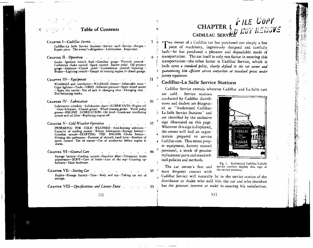
Table of Contents
CHAPTER I—Cadillac Service
Cadillac-La Salle Service Stations—Service card—Service charges-Repair parts—The owner's obligation—Lubrication—Inspection.
CHAPTER I i'lLE
**.f% fs»ov p^^'iys" LtJ hU I i t - / • * • / r —
3 Ar
8 •> CHAPTER II—Operation Locks—Ignition switch lock—Gasoline gauge—Throttle control— Carburetor choke control—Spark control—Starter pedal—Oil pressure gauge—Ammeter—Clutch pedal—Transmission control—Coasting— Brakes—Lighting switch—Danger of running engine in closed garage.
CHAPTER III—Equipment 21 ''
Windshield and ventilation—Windshield cleaner—Adjustable seats— Cigar lighters—Tools—TIRES—Inflation pressure—Spare wheel carrier *' —Spare tire carrier—Use of jack in changing tires—Changing tires— Tire balancing marks.
CHAPTER IV-—Lubrication 30
Lubrication schedule—Lubrication chart—LUBRICANTS—Engine oil —Gear lubricant—Chassis grease—Wheel bearing grease—Water pump grease—ENGINE LUBRICATION^Oil level—Crankcase ventilating -system and oil filter—Replacing engine oil.
CHAPTER V—Cold Weather Operation 37 PREPARING FOR COLD WEATHER—Anti-freezing solutions-Capacity of cooling system—Winter lubrication—Storage battery— Gasoline system—STARTING THE ENGINE—Choke button— « Priming the carburetor—Position of throttle hand lever—Position of spark control—Use of starter—Use of accelerator before engine is ^ warm.
CHAPTER VI—General Care 44
Storage battery—Cooling system—Gasoline filter—Temporary brake adjustments—BODY—Care of finish—Care of the top—Cleaning upholstery—Door hardware.
CHAPTER VII—Storing Car 50
Engine—Storage battery—Tires—Body and top—Taking car out of storage.
CHAPTER VIII—Specifications and License Data . 53
[2]
CADILLAC S E R V
THE owner of a Cadillac car has purchased not simply a fine piece of machinery, ingeniously designed and carefully
built—he has purchased a pleasant and dependable mode of transportation. The car itself is only one factor in securing this transportation—the other factor is Cadillac Service, which is built upon a standard policy, clearly defined to the car owner and guaranteeing him efficient service everywhere at standard prices under factory regulation.
Cadillac-La Salle Service Stations Cadillac Service extends wherever Cadillac and La Salle cars
are sold. Service stations conducted by Cadillac distributors and dealers are designated as "Authorized Cadillac-La Salle Service Stations" and are identified by the exclusive sign illustrated on this page. Wherever this sign is displayed, the owner will find an organization prepared to service Cadillac cars. This means proper equipment, factory trained personnel, a stock of genuine replacement parts and standardized policies and methods.
The car owner's first and most frequent contact with
Fig. 1. Authorized Cadillac-LaSalle service stations display this sign at the service entrance.
Cadillac Service will naturally be in the service station of the distributor or dealer who sold him the car and who therefore has the greatest interest at stake in assuring his satisfaction.
[ 3 ]
mm
m t J 0
b|ev<|rt$ieless, he may feel perfectly free to use his car for eitended.taraWe^without depriving himself of the service benefits
.fO'wbial^ne is entitled at his local service station. He will find l|otier Authorized Cadillac-La Salle Service Stations able and willing to render the same service.
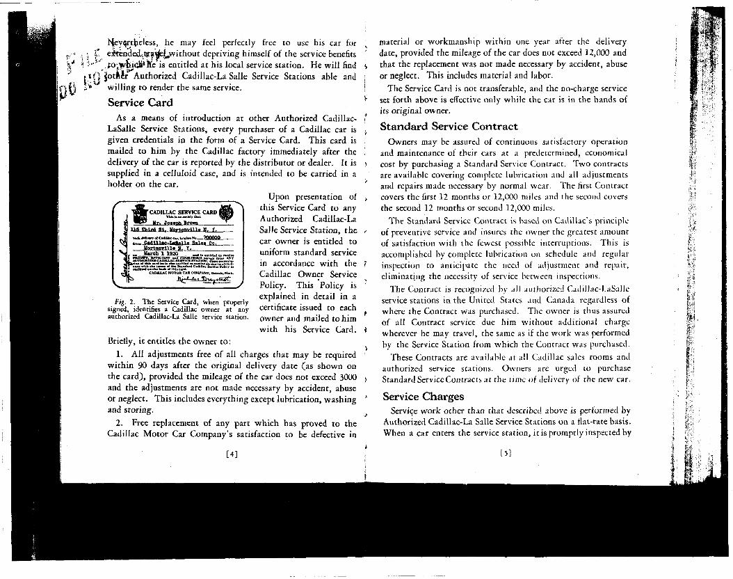
Service Card As a means of introduction at other Authorized Cadillac-
LaSalle Service Stations, every purchaser of a Cadillac car is given credentials in the form of a Service Card. This card is mailed to him by the Cadillac factory immediately after the delivery of the car is reported by the distributor or dealer. It is supplied in a celluloid case, and is intended to be carried in a holder on the car.
Upon presentation of this Service Card to any Authorized Cadillac-La Salle Service Station, the car owner is entitled to uniform standard service in accordance wi th the Cadillac Owner Service Policy. This Policy is explained in detail in a certificate issued to each owner and mailed to him with his Service Card.
Briefly, it entitles the owner to :
1. All adjustments free of all charges that may be required within 90 days after the original delivery date (as shown on the card), provided the mileage of the car does not exceed 3000 and the adjustments are not made necessary by accident, abuse or neglect. This includes everything except lubrication, washing and storing.
2. Free replacement of any part which has proved to the Cadillac Motor Car Company's satisfaction to be defective in
„ Itareh 1 1 9 » _ „ »]S PROMPT, EFFICIENT and COURTEOUS .wnea (nun ANY X g AUTaRaRlZESCAlULLAC SERVICE STATION. U n n ^ w t , . nPKi*lea al tbl . aard Iw la »|M> antltlad to n o w . aanlca In acutd -3 g n K a a W l d n U n n n ; t f e Standard Cadlllaa Sanrtea Palicv a . i= outuAMTan aha baak af tklaaard.
CADILLAC MOTOR CAR COMPANY. Datrelt. M
- L \ ^ & J ~ L S ^ 2 * S 3 £
Fig. 2. The Service Card, when properly signed, identifies a Cadillac owner at any authorized Cadillac-La Salle service station.
[ 4 ]
material or workmanship within one year after the delivery date, provided the mileage of the car does not exceed 12,000 and that the replacement was not made necessary by accident, abuse or neglect. This includes material and labor.
The Service Card is not transferable, and the no-charge service set forth above is effective only while the car is in the hands of its original owner.
Standard Service Contract Owners may be assured of continuous satisfactory operation
and maintenance of their cars at a predetermined, economical cost by purchasing a Standard Service Contract. Two contracts are available covering complete lubrication and all adjustments and repairs made necessary by normal wear. The first Contract covers the first 12 months or 12,000 miles and the second covers the second 12 months or second 12,000 miles.
The Standard Service Contract is based on Cadillac's principle of preventive service and insures the owner the greatest amount of satisfaction wi th the fewest possible interruptions. This is accomplished by complete lubrication on schedule and regular inspection to anticipate the need of adjustment and repair, eliminating the necessity of service between inspections.
The Contract is recognized by all authorized CadiUac-J.aSalle service stations in the United States and Canada regardless of where the Contract was purchased. The owner is thus assured of all Contract service due him without additional charge wherever he may travel, the same as if the work was performed by the Service Station from which the Contract was purchased.
These Contracts are available at all Cadillac sales rooms and authorized service stations. Owners are urged to purchase Standard Service Contracts at the time of delivery of the new car.
Service Charges Service work other than that described above is performed by
Authorized Cadillac-La Salle Service Stations on a flat-rate basis. When a car enters the service station, it is promptly inspected by
[5]
a tester, who then quotes the owner an exact price for the work he finds necessary. The owner authorizes the work at this price, and when he receives his bill, this is the price he pays.
Charges prevailing at Authorized Cadillac-LaSalle Service Stations are based on standard schedules furnished by the Cadillac Motor Car Company. These schedules call for methods and tools approved by the same engineers who designed and built the car, assuring the highest quality of work at the lowest possible price. Standard Price Schedules are open to inspection by owners at any Authorized Cadillac-La Salle Service Station.
Repair Par ts Genuine Cadillac parts, manufactured to the same rigid
specifications as the parts entering into the original assembly of the car, are carried in stock by Authorized Cadillac-La Salle Service Stations. They are sold at uniform prices throughout the United States, and are not subject to the addition of handling, excise or other supplementary charges. Printed price lists, published by the Cadillac Motor Car Company, are open to inspection by owners at any authorized Cadillac distributor's or dealer's establishment.
The Owner's Obligation All of these service facilities are placed at the disposal of the
Cadillac owner, in order that his car may be a continuous source of satisfaction and utility. This result cannot be guaranteed, however, unless the owner fulfills certain definite obligations himself, as follows:
1. To drive the car at moderate speeds for the first 500 miles.
2. To operate the car in accordance with the instructions contained in this manual.
3. To check the engine oil level every 100 to 150 miles, and add oil as often as necessary to keep the indicator at "full."
4. To check the tire pressure at least every week, and keep it up to the recommended pressure—40 pounds in front and rear—on cars driven at high speeds, 45 pounds in front.
[6]
»
5. To add distilled water to the storage battery every 1000 miles, and in warm weather every 500 miles, or at least every two weeks.
6. To have the car lubricated every 1000 miles, or once a month, in accordance with the lubrication schedule on page 29.
7. To take the car to an Authorized Service Station for inspection every 1000 miles, or at least once a month.
Lubrication The first five items above are details which do not necessarily
warrant a visit to the service station. For lubrication, however, the owner is urged to patronize Authorized Cadillac-LaSalle Service Stations, because they are prepared to furnish this service in a manner that cannot be duplicated elsewhere. Only approved lubricants are used, the specifications of which have been worked out by Cadillac engineers to give the best possible results. Workmen who specialize on Cadillac cars know exactly where lubrication points are located and how much lubricant to apply. The charge for this lubrication service is less than half a cent a mile, which includes the cost of the lubricants.
Inspection Preventive service is a fundamental principle of Cadillac
Service. "Preventive service" is the practice of inspecting the car at regular intervals and making those adjustments that need attention before the need becomes an emergency. Inspections should be made every 1000 miles, in order to insure transportation satisfaction. Authorized Cadillac-La Salle Service Stations will make such inspections without charge, provided no dismantling of units is necessary.
The Cadillac owner is urged to take full advantage of this, not only while the car is new, but throughout its entire life.
Preventive service rendered every 1,000 miles or once a m o n t h by an Authorized Cadillac-La Salle Service Station, is the surest guarantee of long life and complete motoring satisfaction at the least possible expense.
[7]
CHAPTER II OPERATION
ONE of the first things the driver of a new car should do is to familiarize himself with the various controls described
in the following chapter.
Locks
Each car is equipped with a hexagonal-handled key which is used to operate the combination ignition and transmission lock, the door lock and the tire carrier lock. In addition, cars that have rumble seats or package compartments fitted with locks have a separate key for these compartments. The compartment key has an oval handle.
The lock number is stamped on each key, but not upon the face of the lock. The owner should make a record of the key numbers as soon as he takes delivery of his car, so that in the event both keys are lost, a duplicate key can easily be obtained from a Cadillac distributor or dealer.
The right front door can be locked from the inside to prevent intruders from forcing their way into the car. This can be done by turning the key to the locked position on the outside before entering the car. The door will then be locked from the outside, although it can be opened from the inside in the usual manner.
Ignition Switch Lock
The lock in the center of the instrument panel controls both the ignition switch and the transmission lock. When the key is turned, the cylinder of the lock will slide out about half an inch, turning on the ignition and unlocking the transmission by means of a cable connection to the shifter shafts. To shut
[8] »
off the ignition and lock the transmission, turn the key to the locked position and push the lock cylinder all the way in. The car can be locked when the transmission is in neutral or in reverse. Do not attempt to shut off the ignition when the transmission is in any forward gear. Be sure to remove the key before leaving the car.
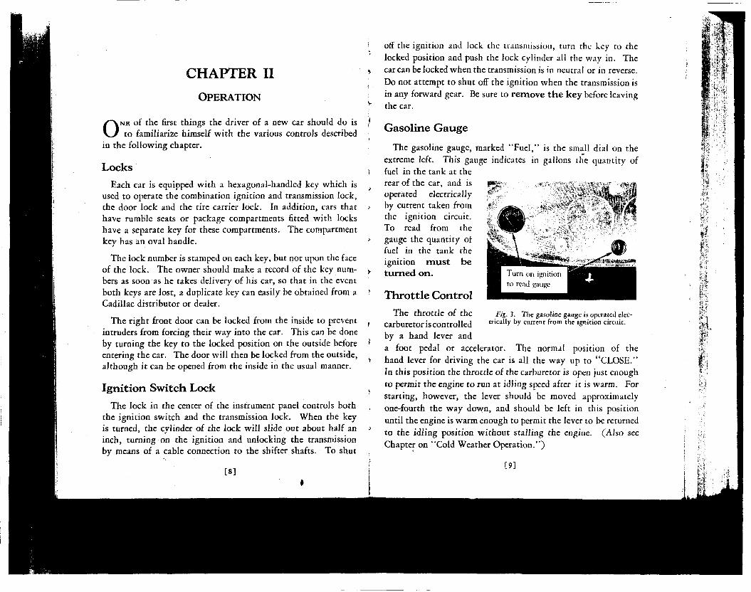
Gasoline Gauge
The gasoline gauge, marked "Fuel," is the small dial on the extreme left. This gauge indicates in gallons the quantity of fuel in the tank at the rear of the car, and is operated electrically by current taken from the ignition circuit. To read from the gauge the quantity of fuel in the tank the ignition must be turned on .
Throt t le Control
The throttle of the Fig. 3. The gasoline gauge is operated elec-
carburetor is controlled t r ically by current from the 'Sni t ion circuit-by a hand lever and a foot pedal or accelerator. The normal position of the hand lever for driving the car is all the way up to "CLOSE." In this position the throttle of the carburetor is open just enough to permit the engine to run at idling speed after it is warm. For starting, however, the lever should be moved approximately one-fourth the way down, and should be left in this position until the engine is warm enough to permit the lever to be returned to the idling position without stalling the engine. (Also see Chapter on "Cold Weather Operation.")
[9]
Carburetor Choke Control
Correct use of the choke control is essential not only to quick
starting of the engine, but also has an important effect on the
life of the engine. The button must be pulled out far enough
in starting to provide an explosive mixture quickly so that the
battery is not unnecessarily discharged by useless cranking.
The button must also be left out far enough during the warming-
up period so that the engine will run without missing and
"popping back."
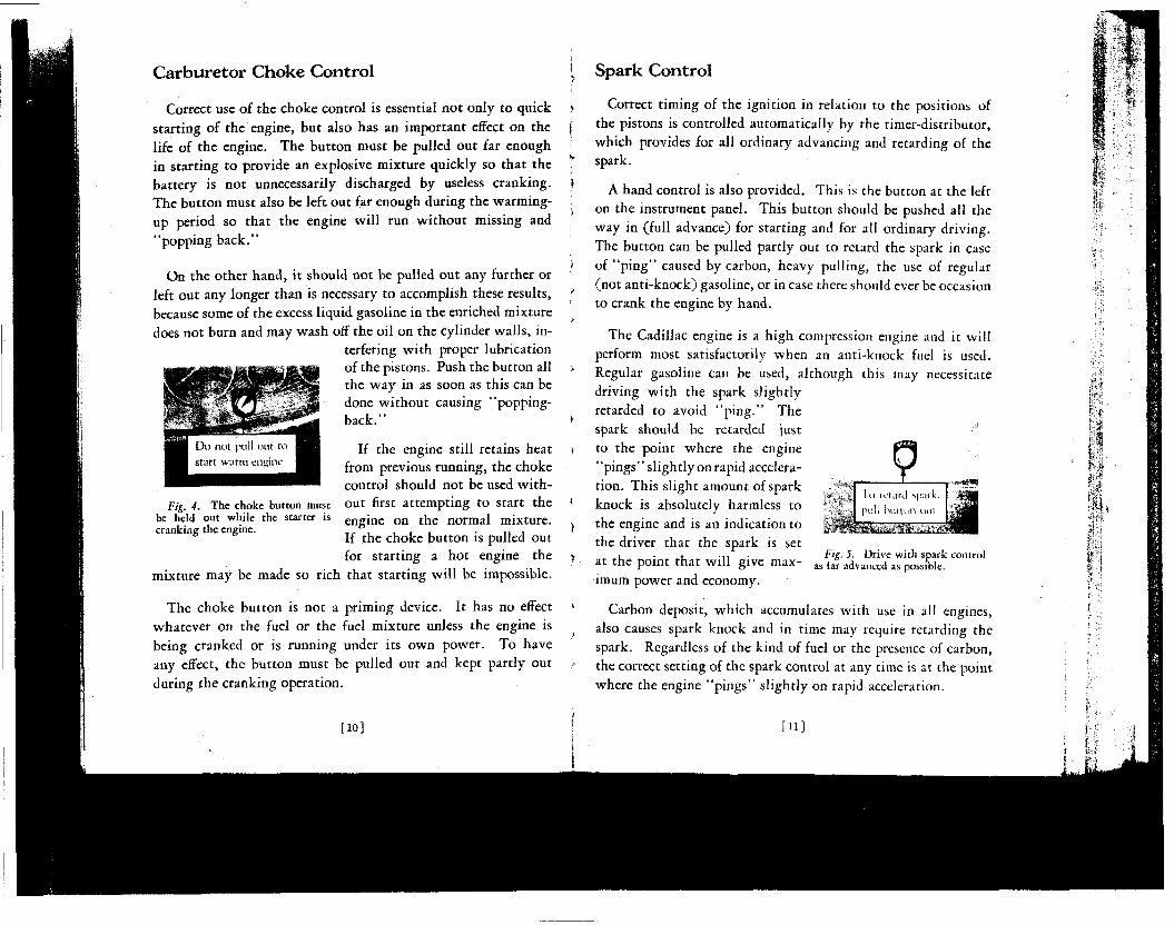
On the other hand, it should not be pulled out any further or left out any longer than is necessary to accomplish these results, because some of the excess liquid gasoline in the enriched mixture does not burn and may wash off the oil on the cylinder walls, in
terfering wi th proper lubrication of the pistons. Push the button all the way in as soon as this can be done without causing "popping-back."
F/g. 4. The choke button must be held out while the starter is cranking the engine.
If the engine still retains heat from previous running, the choke control should not be used without first attempting to start the engine on the normal mixture. If the choke button is pulled out for starting a hot engine the
mixture may be made so rich that starting will be impossible.
The choke button is not a priming device. It has no effect
whatever on the fuel or the fuel mixture unless the engine is
being cranked or is running under its own power. To have
any effect, the button must be pulled out and kept partly out
during the cranking operation.
[10]
Spark Control
Correct timing of the ignition in relation to the positions of the pistons is controlled automatically by the timer-distributor, which provides for all ordinary advancing and retarding of the spark.
A hand control is also provided. This is the button at the left
on the instrument panel. This button should be pushed all the
way in (full advance) for starting and for all ordinary driving.
The button can be pulled partly out to retard the spark in case
of "p ing" caused by carbon, heavy pulling, the use of regular
(not anti-knock) gasoline, or in case there should ever be occasion
to crank the engine by hand.
The Cadillac engine is a high compression engine and it will perform most satisfactorily when an anti-knock fuel is used. Regular gasoline can be used, although this may necessitate driving wi th the spark slightly retarded to avoid "p ing . " The spark should be retarded just to the point where the engine ' 'pings' ' slightly on rapid acceleration. This slight amount of spark knock is absolutely harmless to the engine and is an indication to the driver that the spark is set at the point that will give maximum power and economy.
Fig. 5. Drive with spark control as far advanced as possible.
Carbon deposit, which accumulates with use in all engines, also causes spark knock and in time may require retarding the spark. Regardless of the kind of fuel or the presence of carbon, the correct setting of the spark control at any time is at the point where the engine "pings" slightly on rapid acceleration.
[11]
Starter Pedal
The starter pedal is at the right of the accelerator. Pushing this pedal forward brings into action the electric motor that cranks the engine for starting. Do not push the starter pedal when the engine is running.
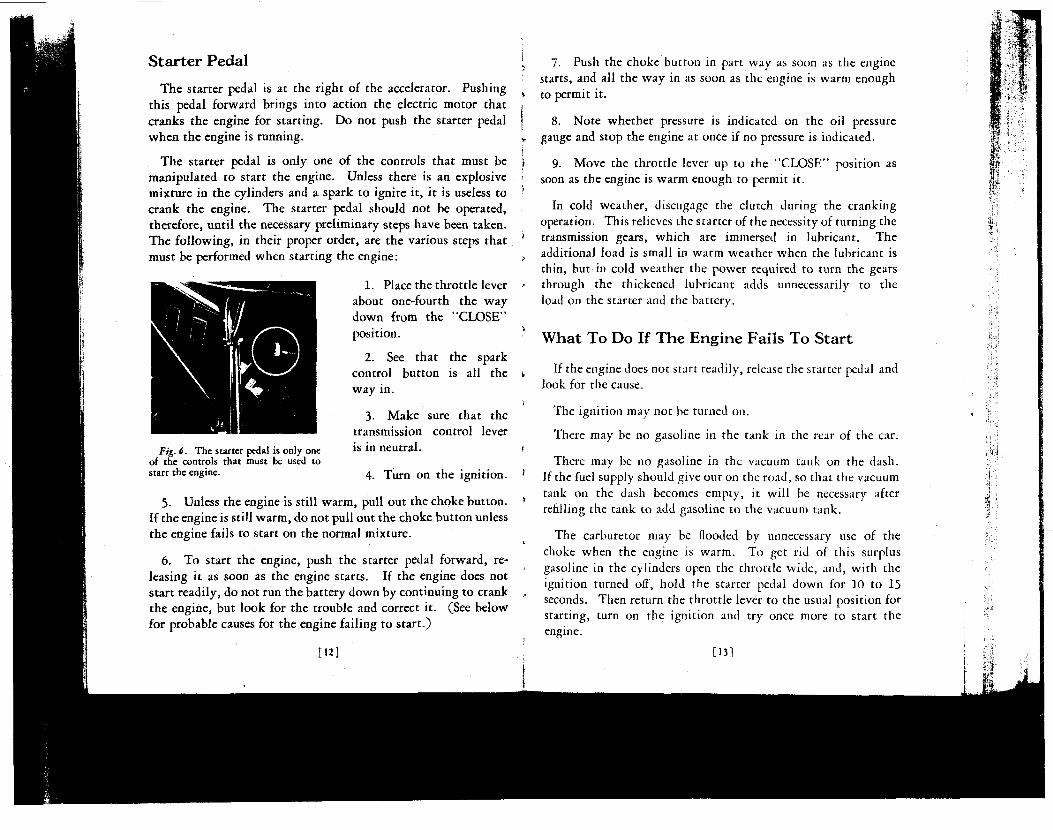
The starter pedal is only one of the controls that must be manipulated to start the engine. Unless there is an explosive mixture in the cylinders and a spark to ignite it, it is useless to crank the engine. The starter pedal should not be operated, therefore, until the necessary preliminary steps have been taken. The following, in their proper order, are the various steps that must be performed when starting the engine:
1. Place the throttle lever about one-fourth the way down from the "CLOSE" position.
2. See that the spark control button is all the way in.
3. Make sure that the transmission control lever is in neutral.
4. Turn on the ignition.
5. Unless the engine is still warm, pull out the choke button. If the engine is still warm, do not pull out the choke button unless the engine fails to start on the normal mixture.
6. To start the engine, push the starter pedal forward, releasing it as soon as the engine starts. If the engine does not start readily, do not run the battery down by continuing to crank the engine, but look for the trouble and correct it. (See below for probable causes for the engine failing to start.)
Fig. 6. The starter pedal is only one of the controls that must be used to start the engine.
[12]
7. Push the choke button in part way as soon as the engine starts, and all the way in as soon as the engine is warm enough to permit it.
8. Note whether pressure is indicated on the oil pressure gauge and stop the engine at once if no pressure is indicated.
9. Move the throttle lever up to the "CLOSE" position as soon as the engine is warm enough to permit it.
In cold weather, disengage the clutch during the cranking operation. This relieves the starter of the necessity of turning the transmission gears, which are immersed in lubricant. The additional load is small in warm weather when the lubricant is thin, but in cold weather the power required to turn the gears through the thickened lubricant adds unnecessarily to the load on the starter and the battery.
What To Do If The Engine Fails To Start
If the engine does not start readily, release the starter pedal and look for the cause.
The ignition may not be turned on.
There may be no gasoline in the tank in the rear of the car.
There may be no gasoline in the vacuum tank on the dash. If the fuel supply should give out on the road, so that the vacuum tank on the dash becomes empty, it will be necessary after refilling the tank to add gasoline to the vacuum tank.
The carburetor may be flooded by unnecessary use of the choke when the engine is warm. To get rid of this surplus gasoline in the cylinders open the throttle wide, and, with the ignition turned off, hold the starter pedal down for 10 to 15 seconds. Then return the throttle lever to the usual position for starting, turn on the ignition and try once more to start the engine.
[13]
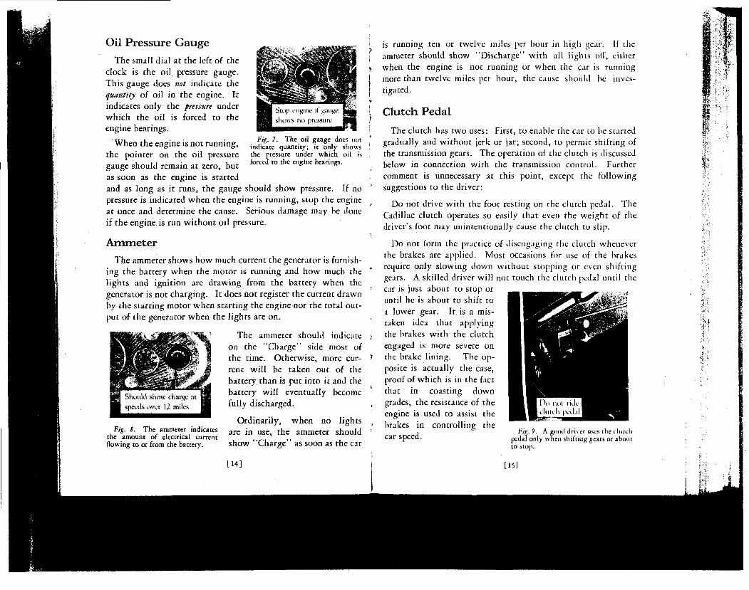
Fig. 7. The oil gauge does not indicate quantity; it only shows the pressure under which oil is forced to the engine bearings.
Oil Pressure Gauge
The small dial at the left of the clock is the oil pressure gauge. This gauge does not indicate the quantity of oil in the engine. It indicates only the pressure under which the oil is forced to the engine bearings.
When the engine is not running, the pointer on the oil pressure gauge should remain at zero, but as soon as the engine is started and as long as it runs, the gauge should show pressure. If no pressure is indicated when the engine is running, stop the engine at once and determine the cause. Serious damage may be done if the engine is run without oil pressure.
Ammeter
The ammeter shows how much current the generator is furnishing the battery when the motor is running and how much the lights and ignition are drawing from the battery when the generator is not charging. It does not register the current drawn by the starting motor when starting the engine nor the total output of the generator when the lights are on.
The ammeter should indicate on the "Charge" side most of the time. Otherwise, more current will be taken out of the battery than is put into it and the battery will eventually become fully discharged.
Ordinarily, when no lights Fig. 8. The ammeter indicates a r e i n u s e t n e ammeter should
the amount of electrical current flowing to or from the battery. show 'Charge as soon as the car
[14]
is running ten or twelve miles per hour in high gear. If the ammeter should show "Discharge" with all lights off", either when the engine is not running or when the car is running more than twelve miles per hour, the cause should be investigated.
Clutch Pedal
The clutch has two uses: First, to enable the car to be started gradually and without jerk or jar; second, to permit shifting of the transmission gears. The operation of the clutch is discussed below in connection with the transmission control. Further comment is unnecessary at this point, except the following suggestions to the driver:
Do not drive with the foot resting on the clutch pedal. The Cadillac clutch operates so easily that even the weight of the driver's foot may unintentionally cause the clutch to slip.
Do not form the practice of disengaging the clutch whenever the brakes are applied. Most occasions for use of the brakes require only slowing down without stopping or even shifting gears. A skilled driver will not touch the clutch pedal until the car is just about to stop or until he is about to shift to a lower gear. It is a mistaken idea that applying the brakes wi th the clutch engaged is more severe on the brake lining. The opposite is actually the case, proof of which is in the fact that in coasting down grades, the resistance of the engine is used to assist the brakes in controlling the
, Fig. 9. A good driver uses the clutch Car Speed. pedal only when shifting gears or about
to stop.
[151
It will be observed in operating the clutch pedal that the pedal offers almost no resistance until it has been moved about one inch. It is at this point that it actually begins to disengage the clutch. It is important that the pedal have this "lost mot ion." If the full pressure of the clutch springs is felt just as soon as the pedal is moved, the control rod should be readjusted. Failure to make this adjustment will result in the clutch slipping.
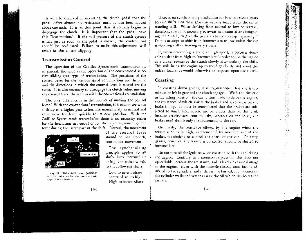
Transmission Control
The operation of the Cadillac Syncro-mesh transmission is, in general, the same as the operation of the conventional selective sliding-gear type of transmission. The positions of the control lever for the various speed combinations are the same and the directions in which the control lever is moved are the same. It is also necessary to disengage the clutch before moving the control lever, the same as wi th the conventional transmission.
The only difference is in the manner of moving the control lever.' With the conventional transmission, it is customary when shifting to a higher gear to hesitate momentarily in neutral and then move the lever quickly to its new position. With the Cadillac Syncro-mesh transmission there is no necessity either for the hesitation in neutral or for the rapid movement of the lever during the latter part of the shift. Instead, the movement
of t h e c o n t r o l l eve r should be one smooth, continuous movement.
T h e s y n c h r o n i z i n g principle applies to all shifts into intermediate or high; in other words, to the following shifts:
Low to intermediate Intermediate to high High to intermediate
Fig. 10. The control lever positions are the same as for the conventional type of transmission.
[16]
There is no synchronizing mechanism for low or reverse gears because shifts into these gears are usually made when the car is standing still. When shifting from neutral to low or reverse, therefore, it may be necessary to await an instant after disengaging the clutch, to give the gears a chance to stop "spinning." Do not attempt to shift from intermediate to low unless the car is standing still or moving very slowly.
If, when descending a grade at high speed, it becomes desirable to shift from high to intermediate in order to use the engine as a brake, re-engage the clutch slowly after making the shift. This will bring the engine up to speed gradually and avoid the sudden load that would otherwise be imposed upon the clutch.
Coasting
In coasting down grades, it is recommended that the transmission be left in gear and the clutch engaged. With the throttle in the idling position, the car is thus made to drive the engine, the resistance of which assists the brakes and saves wear on the brake lining. It must be remembered that the brakes are subjected to much more severe use on grades than on the level, because gravity acts continuously, whereas on the level, the brakes need absorb only the momentum of the car.
Ordinarily, the resistance offered by the engine when the transmission is in high, supplemented by moderate use of the brakes, is sufficient to control the speed of the car. On steep grades, however, the transmission control should be shifted to intermediate.
Do not turn off the ignition when coasting with the car driving the engine. Contrary to a common impression, this does not appreciably increase the resistance, and is likely to cause damage to the engine. Even with the throttle closed, some fuel is admitted to the cylinders, and if this is not burned, it condenses on the cylinder walls and washes away the oil which lubricates the pistons.
117]
Brakes
The foot brakes are internal brakes of the shoe type, applied on all four wheels through a mechanical linkage.
When applying the brakes while driving on wet asphalt streets or slippery roads, more care should be exercised and more time should be allowed for stopping the car than is necessary on dry pavements. The brakes should be applied gently while the clutch is still engaged. The clutch should not be released until the car has almost stopped.
Do not attempt sudden stops. Cadillac four-wheel brakes minimize the possibility of skidding under slippery conditions, but their effectiveness should not induce anyone to drive less carefully.
As the brake lining wears, the pedal must be pushed farther down to apply the brakes. Do not wait until the pedal goes all the way to the floor board before having the brakes readjusted. Readjustment is recommended as soon as the pedal must be pushed down to within one inch of the floor board. A temporary adjustment of the brakes is explained on page 47-
For parking, the brakes are operated by the hand lever at the right of the transmission control lever.
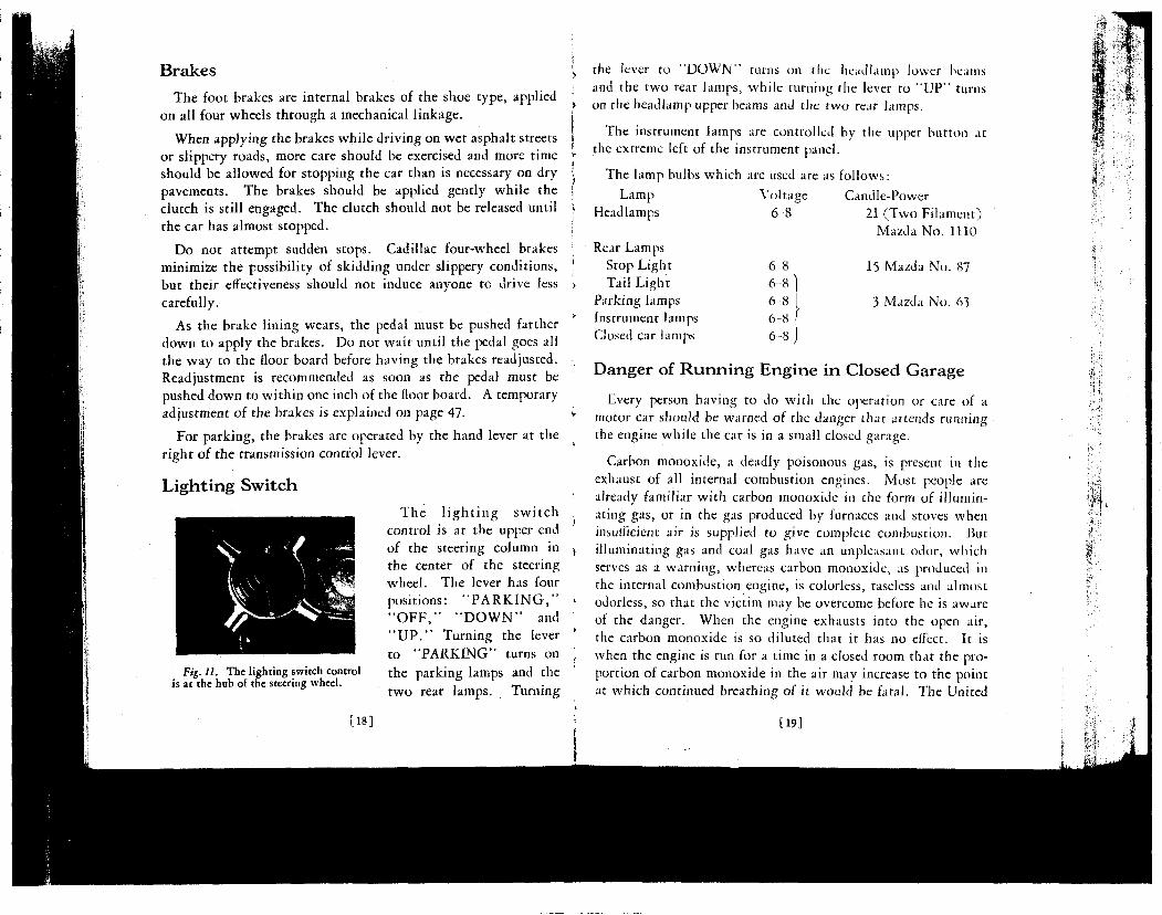
The l i g h t i n g swi tch control is at the upper end of the steering column in the center of the steering wheel. The lever has four positions: " P A R K I N G , " " O F F , " " D O W N " and " U P . " Turning the lever to "PARKING" turns on the parking lamps and the two rear lamps. Turning
Lighting Switch
Fig. 11. The lighting switch control is at the hub of the steering wheel.
[18]
the lever to "DOWN" turns on the headlamp lower beams and the two rear lamps, while turning the lever to " U P " turns on the headlamp upper beams and the two rear lamps.
The instrument lamps are controlled by the upper button at the extreme left of the instrument panel.
The lamp bulbs which are used are as follows:
Lamp Headlamps
Rear Lamps Stop Light Tail Light
Parking lamps Instrument lamps Closed car lamps
Voltage 6-8
6 8 6-8 ] 6 8 ! 6-8 f 6-8 j
Candle-Power 21 (Two Filament)
Mazda No. 1U0
15 Mazda No. 87
3 Mazda No. 63
Danger of Running Engine in Closed Garage
Every person having to do with the operation or care of a motor car should be warned of the danger that attends running the engine while the car is in a small closed garage.
Carbon monoxide, a deadly poisonous gas, is present in the exhaust of all internal combustion engines. Most people are already familiar with carbon monoxide in the form of illuminating gas, or in the gas produced by furnaces and stoves when insufficient air is supplied to give complete combustion. But illuminating gas and coal gas have an unpleasant odor, which serves as a warning, whereas carbon monoxide, as produced in the internal combustion engine, is colorless, taseless and almost odorless, so that the victim may be overcome before he is aware of the danger. When the engine exhausts into the open air, the carbon monoxide is so diluted that it has no effect. It is when the engine is run for a time in a closed room that the proportion of carbon monoxide in the air may increase to the point at which continued breathing of it would be fatal. The United
[19]
States Public Health Service advises that the average automobile engine warming up in a single car garage will give off enough carbon monoxide in three minutes to endanger life.
Proper precaution must be taken in cold weather when the natural tendency is to keep the garage doors and windows closed. The practice of letting the engine warm up in a closed garage before opening the doors is unsafe. The risk is made greater by the fact that the enriching of the mixture by manipulation of the carburetor choke increases the amount of carbon monoxide formed.
[20]
CHAPTER III
E Q U I P M E N T
IN addition to the controls and instruments used in driving, the car is equipped with various devices which are for the
convenience and comfort of the occupants, and are used only as occasion demands. It is suggested that the driver anticipate his use of such equipment by becoming familiar at once with the directions contained in this chapter.
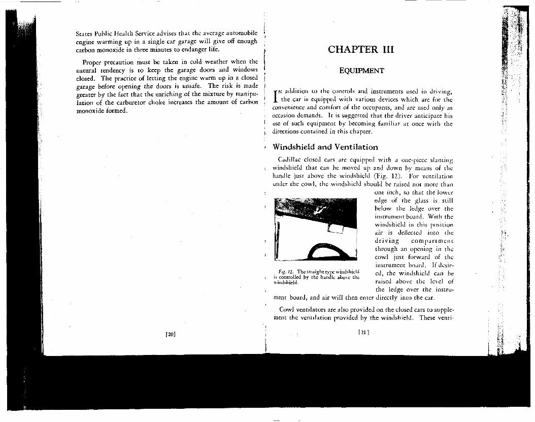
Windshield and Ventilation
Cadillac closed cars are equipped with a one-piece slanting windshield that can be moved up and down by means of the handle just above the windshield (Fig. 12). For ventilation under the cowl, the windshield should be raised not more than
one inch, so that the lower edge of the glass is still below the ledge over the instrument board. With the windshield in this position air is deflected into the d r i v i n g c o m p a r t m e n t through an opening in the cowl just forward of the instrument board. If desir-
• f « - « - The straight type windshield e t] t j , e windshield can be is controlled by the handle above the windshield. raised above the level of
the ledge over the instrument board, and air will then enter directly into the car.
Cowl ventilators are also provided on the closed cars to supplement the ventilation provided by the windshield. These venti-
[21]
lators are at the sides of the cowl compartment and open toward the rear, serving as outlets for the air entering under the windshield.
In warm weather, satisfactory ventilation in the front compartment cannot be expected unless the hood doors are open. Ordinarily, these should be opened at the beginning of warm weather and left open for the season. The temperature in the front compartment can thereafter be controlled by the windshield and ventilators.
Windshield Cleaner
The windshield cleaner consists of two wiper blades, operated by the suction or vacuum in the passages between the carburetor and the engine. The cleaner is controlled by the lower button at the extreme left-hand end of the instrument board. This button, when pulled all the way out, will cause one blade to work on each half of the windshield, cleaning the entire surface. Pulling the button only half way out will cause both blades to operate on the left-hand half of the windshield, cleaning only the part in front of the driver.
To park both blades at the extreme left of the windshield when they are not needed to clean the glass, pull the control button halfway out, wait until the left-hand blade travels over to meet the right-hand blade and returns with it to the left-hand side; then push the button all the way in.
Adjustable Seat
The front seat is adjustable on all Cadillac closed cars, except those which are intended to be chauffeur-driven. Except on the five-passenger coupe, the entire front seat can be moved forward or backward. This adjustment is controlled by a handle on the center of the seat base, just above the floorboards. As the front seat on the five-passenger coupe is divided, only the driver's half of the seat is adjustable.
[22]
Cigar Lighter
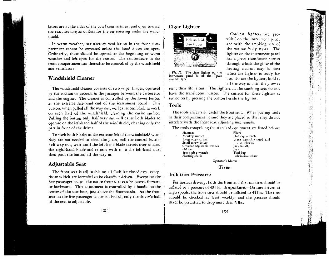
Cordless lighters are provided on the instrument panel and with the smoking sets of the various body styles. The lighter on the instrument panel has a green translucent button through which the glow of the heating element may be seen
FiS. 11. The cigar lighter on the w h e n t h e ]j„hter is ready for instrument panel is or the pass ° J
around" type. use. To use the lighter, hold it all the way in until the glow is
seen; then lift it out. The lighters in the smoking sets do not have the translucent button. The current for these lighters is turned on by pressing the button beside the lighter. Tools
The tools are carried under the front seat. When putting tools in their compartment be sure they are placed so that they do not interfere with the front seat adjusting mechanism.
The tools comprising the standard equipment are listed below: Hammer Pliers Monkey wrench Hub cap wrench Large screw-driver Brace wrench (wood and Small screw-driver disc wheels) Crescent adjustable wrench Jack handle Oil can Jack Spark plug wrench Tool bag Starting crank Lubrication chart
Operator's Manual
Tires
Inflation Pressure For normal driving, both the front and the rear tires should be
inflated to a pressure of 40 lbs. Important—On cars driven at high speeds, the front tires should be inflated to 45 lbs. The tires should be checked at least weekly, and the pressure should never be permitted to drop more than 5 lbs.
[23]
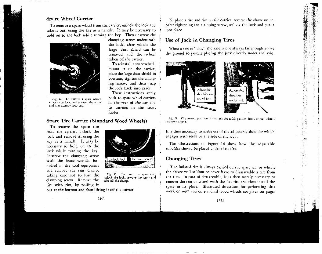
Spare Wheel Carrier To remove a spare wheel from the carrier, unlock the lock and
take it out, using the key as a handle. It may be necessary to hold on to the lock while turning the key. Then unscrew the
clamping screw underneath the lock, after which the large dust shield can be removed and the wheel taken off the carrier.
To reinstall a spare wheel, mount it on the carrier, place the large dust shield in position, tighten the clamping screw, and then snap the lock back into place.
These instructions apply both to spare wheel carriers on the-rear of the car and to carriers in the front fender.
Fig. 14. To remove a spare wheel, unlock the lock, and remove the screw and the dummy hub cap.
Spare Tire Carrier (Standard Wood Wheels) To remove the spare tire
from the carrier, unlock the lock and remove it, using the key as a handle. It may be necessary to hold on to the lock while turning the key. Unscrew the clamping screw with the brace wrench furnished in the tool equipment and remove the rim clamp, taking care not to lose the clamping screw. Remove the tire with rim, by pulling it out at the bottom and then lifting it off the carrier.
Fig. 15. To remove a spare tire, unlock the lock, remove the screw and take off the clamp.
[24]
To place a tire and rim on the carrier, reverse the above order. After tightening the clamping screw, unlock the lock and put it into place.
Use of Jack in Changing Tires
When a tire is "flat," the axle is not always far enough above the ground to permit placing the jack directly under the axle.
Fig. 16. The correct position of the jack for raising either front or rear wheels is shown above.
It is then necessary to make use of the adjustable shoulder which engages with teeth on the side of the jack.
The illustrations in Figure 16 show how the adjustable shoulder should be placed under the axles.
Changing Tires
If an inflated tire is always carried on the spare rim or wheel, the driver will seldom or never have to disassemble a tire from the rim. In case of tire trouble, it is then merely necessary to remove the rim or wheel with the flat tire and then install the spare in its place. Illustrated directions for performing this work on wire and on standard wood wheels are given on pages
[25]
27 and 28. Disc and demountable wood wheels are changed in
the same manner as wire wheels except that the hub caps should
not be removed.
Tire Balancing Marks
The tires are balanced to offset the weight of the valve stem.
If a tire is removed, it must be re-installed in its original position
with respect to the rim; otherwise the tire and wheel will be
unbalanced.
A small red or black square is accordingly branded in the rubber
on the side of each tire. This mark must always be in line with
the valve stem.
1261
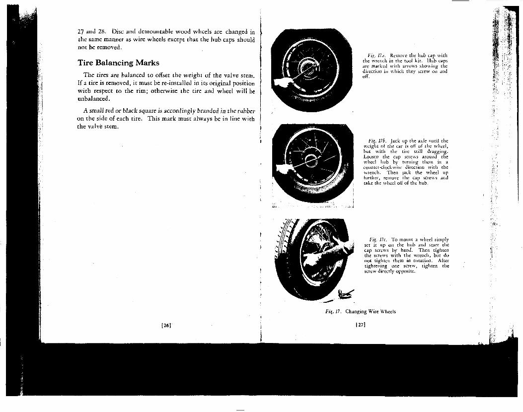
Fig. 17.1. Remove the hub cap with the wrench in the tool kit. Hub caps are marked with arrows showing the direction in which they screw on and off.
Fig. 17b. Jack up the axle until the weight of the car is off of the wheel, but with the tire still dragging. Loosen the cap screws around the wheel hub by turning them in a counter-clockwise direction with the wrench. Then jack the wheel up further, remove the cap screws and take the wheel off of the hub.
Fig. 17c. To mount a wheel simply set it up on the hub and start the cap screws by hand. Then tighten the screws with the wrench, but do not tighten them in rotation. After tightening one screw, tighten the screw directly opposite.
Fit,. 17. Changing Wire Wheels
[27]
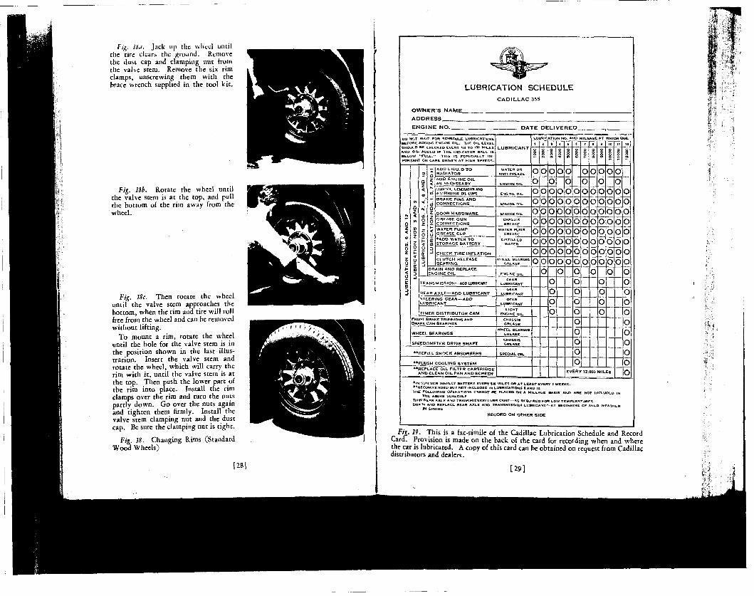
Fig. UJ. Jack up the wheel until the tire clears the ground. Remove the dust cap and clamping nut from the valve stem. Remove the six rim clamps, unscrewing them with the brace wrench supplied in the tool kit.
Fig. 18b. Rotate the wheel until the valve stem is at the top, and pull the bottom of the rim away from the wheel.
Fig. 18c. Then rotate the wheel umil the valve stem approaches the bottom, when the rim and tire will roll free from the wheel and can be removed without lifting.
To mount a rim, rotate the wheel until the hole for the valve stem is in the position shown in the last illustration. Insert the valve stem and rotate the wheel, which will carry the rim with it, until the valve stem is at the top. Then push the lower part of the rim into place. Install the rim clamps over the rim and turn the nuts partly down. Go over the nuts again and tighten them firmly. Install the valve stem clamping nut and the dust cap. Be sure the clamping nut is tight.
Fig. 18. Changing Rims (Standard Wood Wheels)
[28]
LUBRICATION SCHEDULE CADIULAC 355
OWNERS NAME_ ADDRESS ENGINE NO. _DATE D£I_IVERED_
DO NOT WAIT FOR SCHEDULE LUBRICATIONS BEFORE ADOING ENGINE OIL. THE Oil. LEVEL SHOULD BE CHECKED EVERY »W TO '5° MILES AMD OIL ADDED IF THE INDICATOR BALL IS BELOW ••FULL.•• TH.S IS ESPECIALLY IMPORTANT ON CARS DRIVEN AT HIGH SPEEDS.
LUBRICANT
DOOR H A R D W A R E
CHECK T I R E I N F L A T I O N
TRANSM ISSION—ADO LUBRICANT
REAR A X L E — A D D L U B R I C A N T
T IMER D ISTRIBUTOR C A M
WHEEL BEARINGS
o ENGINE OIL
ENGINE Oil,
^.U BR 1 CATION !• ' .AND MILEAGE AT WHICH DUE
o|o
o o
o
o lo o o
o
o o
SPEEDOMETER DRIVE S H A F T
* * R E P I L L S H O C K ABSORBERS
* » F L U S H COOLING SYSTEM
O
IO
o o
iOl
o
o o
o iOl
o ,ol o o o o o o
;0
o
o
o
o
IO'
Pi
p p
ool
o
op oo
o JO
o
EVERY 12.000 M I L E S
o
o
* IN SUM.MCR INSPECT BATTERY EVERV 500 MILES OB AT LEAST EVERY Z WEEKS. ••RECOMMENDED BUT NOT INCLUDED IN LUBRICATIONS 6 AND 12. THE FOLLOWING OPERATIONS CANNOT BE PLACED ON A MILEAGE BASIS ANO ARC NOT (MCt-UOED ll
THE ABOVE SCHEDULE THIN B E » R AXLC AND TRANSMISSION LUBRICANT—AS REQUIRED FOR LOW TEMPERATURES. DRA'N AND REPLACE REAR AXLE ANO TRANSMISSION LtjBWICANT — AT BEGINNING OF MILD WEATHEI
IN SPRING
RECORD O N O T H E R S I D E
Fig. 19. This is a fac-simile of the Cadillac Lubrication Schedule and Record Card. Provision is made on the back of the card for recording when and where the car is lubricated. A copy of this card can be obtained on request from Cadillac distributors and dealers.
[29]
CHAPTER IV LUBRICATION
Lubrication Schedule
SYSTEMATIC lubrication, at regular mileage intervals, is the only kind that is effective. On page 29 is a complete lubri
cation schedule, which, if faithfully followed, will insure correct lubrication for each wearing surface.
The unit of the schedule is 12000 miles, which is divided into twelve 1000-mile intervals. Corresponding to these is a series of twelve consecutive groups of lubricating operations. When the car has traveled 1000 miles, the points enumerated under Lubrication No. 1 should receive attention. At 2000 miles, Lubrication No. 2 is due, and so on until at 12000 miles, Lubrication No. 12 should be performed. At 13000 miles, the schedule begins again wi th Lubrication No. 1.
It will be noticed from the schedule that there are actually only four different lubrication operations, but that they are numbered according to the various times that they come due.
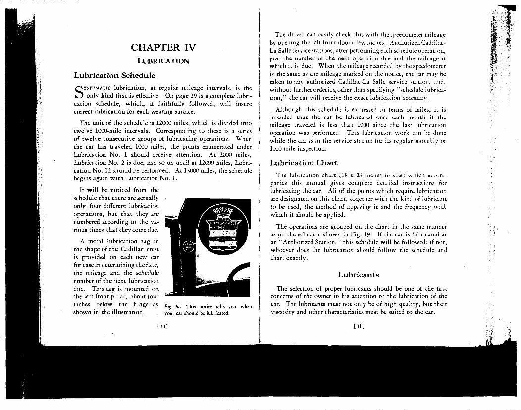
A metal lubrication tag in the shape of the Cadillac crest is provided on each new car for ease in determining the date, the mileage and the schedule number of the next lubrication due. This tag is mounted on the left front pillar, about four inches below the hinge as Fig 20 T h i s n o t k e t d l s y o u w h e n
Shown in the i l lustration. your car should be lubricated.
[30]
The driver can easily check this with the speedometer mileage by opening the left front door a few inches. Authorized Cadillac-La Salle service stations, after performing each schedule operation, post the number of the next operation due and the mileage at which it is due. When the mileage recorded by the speedometer is the same as the mileage marked on the notice, the car may be taken to any authorized Cadillac-La Salle service station, and, without further ordering other than specifying "schedule lubricat ion," the car will receive the exact lubrication necessary.
Although this schedule is expressed in terms of miles, it is intended that the car be lubricated once each month if the mileage traveled is less than 1000 since the last lubrication operation was performed. This lubrication work can be done while the car is in the service station for its regular monthly or 1000-mile inspection.
Lubrication Chart
The lubrication chart (18 x 24 inches in size) which accompanies this manual gives complete detailed instructions for lubricating the car. All of the points which require lubrication are designated on this chart, together with the kind of lubricant to be used, the method of applying it and the frequency with which it should be applied.
The operations are grouped on the chart in the same manner as on the schedule shown in Fig. 19- If the car is lubricated at an "Authorized Station," this schedule will be followed; if not, whoever does the lubrication should follow the schedule and chart exactly.
Lubricants
The selection of proper lubricants should be one of the first concerns of the owner in his attention to the lubrication of the car. The lubricants must not only be of high quality, but their viscosity and other characteristics must be suited to the car.
[31]
The owner is urged to consult the distributor or dealer from whom he purchased his car in regard to the names of lubricants which have been tested and approved for use in the Cadillac car.
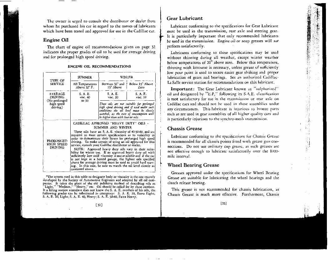
Engine Oil The chart of engine oil recommendations given on page 32
indicates the proper grades of oil to be used for average driving and for prolonged high speed driving.
ENGINE OIL RECOMMENDATIONS
TYPE OF SERVICE
AVERAGE DRIVING
(No prolonged high speed driving)
PROLONGED HIGH SPEED
DRIVING
SUMMER
All Temperatures Above 32° F.
S. A. E. vise. 40
or 50
WINTER
Between 32° and 15° Above
S. A. E. vise. 20
Below 15° Above Zero
S. A. E. vise. 10
These oils are not suitable for prolonged high speed driving and if used under such conditions the oil level must be closely watched, as the rate of consumption will be higher than with heavier oils.
CADILLAC APPROVED "HEAVY DUTY" OILS-SUMMER AND WINTER
These oils have an S. A. E. viscosity of 40-50-60, and are required to meet certain specifications as to volatility in order to demonstrate their fitness for prolonged high speed driving. To make certain of using an oil approved for this service, consult your Cadillac distributor or dealer.
NOTE: Approved heavy duty oils vary in their suitability for winter use. If an approved heavy duty oil with sufficiently low cold viscosity is not available and if the car is not kept in a heated garage, the lighter oils specified above for average driving must be used to avoid hard starting. In this case, be sure to watch the oil level closely as cautioned above.
*The system used in this table to designate body or viscosity is the one recently developed by the Society of Automotive Engineers and adopted by all oil companies. It takes the place of the old indefinite method of describing oils as "Light," "Medium," "Heavy," etc. Oil should be called for by these numbers. If a filling station attendant does not know the S. A. E. numbers of his oils, the following grades can be substituted in emergency: S. A. E. 10, Extra Light; S. A. E. 20, Light; S. A. E. 40, Heavy; S. A. E. 50-60, Extra Heavy.
[32]
Gear Lubricant
Lubricant conforming to the specifications for Gear Lubricant must be used in the transmission, rear axle and steering gear. It is particularly important that only recommended lubricants be used in the transmission. Engine oil or soap greases will not perform satisfactorily.
Lubricants conforming to these specifications may be used without thinning during all weather, except winter weather below temperatures of 20° above zero. Below this temperature, thinning wi th kerosene is necessary, unless grease of sufficiently low pour point is used to secure easier gear shifting and proper lubrication of gears and bearings. See an authorized Cadillac-La Salle service station for recommendations on this lubricant.
I m p o r t a n t : The Gear Lubricant known as "sulphurized" oil and designated by " E . P , " following its S.A.E. classification is n o t satisfactory for use in the transmission or rear axle on Cadillac cars and should not be used in these assemblies under any circumstances. This lubricant is injurious to bronze parts such as are used in gear assemblies of all higher quality cars and is particularly injurious to the synchro-mesh transmission.
Chassis Grease
Lubricant conforming to the specifications for Chassis Grease is recommended for all chassis points fitted with grease gun connections. Do not use ordinary cup grease, as such greases are not effective enough to lubricate satisfactorily over the 1000-mile interval.
Wheel Bearing Grease
Greases approved under the specifications for Wheel Bearing Grease are suitable for lubricating the wheel bearings and the clutch release bearing.
This grease is not recommended for chassis lubrication, as Chassis Grease is much more effective. Furthermore, Chassis
[33]
Grease or ordinary cup grease should not be used in the wheel bearings as such lubricants do not have a sufficiently high melting point to render satisfactory service.
Water P u m p Grease A water-resistant calcium soap grease is recommended for use
in the water pump grease cup. Only greases that meet the specifications for Water Pump Grease should be used; other greases will be dissolved into the cooling system liquid.
The owner of a Cadillac car is urged to have his car put on schedule lubrication at an authorized Cadillac-La Salle service station; in this way he is assured of having the proper lubricants used for all lubricating points at the proper mileage intervals.
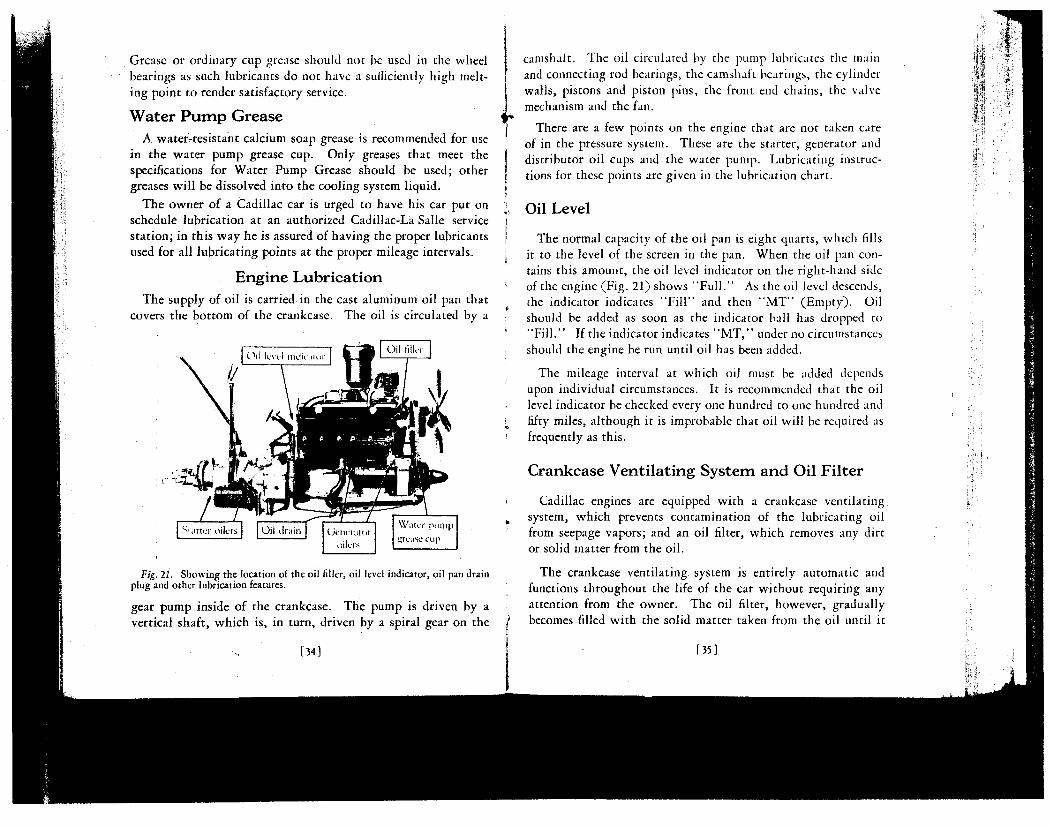
Engine Lubrication The supply of oil is carried in the cast aluminum oil pan that
covers the bottom of the crankcase. The oil is circulated by a
Fig. 21. Showing the location of the oil filler, oil level indicator, oil pan drain plug and other lubrication features.
gear pump inside of the crankcase. The pump is driven by a vertical shaft, which is, in turn, driven by a spiral gear on the
[34]
camshaft. The oil circulated by the pump lubricates the main and connecting rod bearings, the camshaft bearings, the cylinder walls, pistons and piston pins, the front end chains, the valve mechanism and the fan.
There are a few points on the engine that are not taken care of in the pressure system. These are the starter, generator and distributor oil cups and the water pump. Lubricating instructions for these points are given in the lubrication chart.
Oil Level
The normal capacity of the oil pan is eight quarts, which fills it to the level of the screen in the pan. When the oil pan contains this amount, the oil level indicator on the right-hand side of the engine (Fig. 21) shows "Ful l . " As the oil level descends, the indicator indicates "F i l l " and then " M T " (Empty). Oil should be added as soon as the indicator ball has dropped to "Fi l l . " If the indicator indicates " M T , " under no circumstances should the engine be run until oil has been added.
The mileage interval at which oil must be added depends upon individual circumstances. It is recommended that the oil level indicator be checked every one hundred to one hundred and fifty miles, although it is improbable that oil will be required as frequently as this.
Crankcase Ventilating System and Oil Filter
Cadillac engines are equipped with a crankcase ventilating system, which prevents contamination of the lubricating oil from seepage vapors; and an oil filter, which removes any dirt or solid matter from the oil.
The crankcase ventilating system is entirely automatic and functions throughout the life of the car without requiring any attention from the owner. The oil filter, however, gradually becomes filled with the solid matter taken from the oil until it
[35]
becomes so clogged that it ceases to function. The lubrication schedule as followed by authorized Cadillac-La Salle service stations provides for testing the oil filter as part of the regular 2000 mile lubrication. Filter cartridges should be replaced at least every 12,000 miles. Replacement cartridges can be obtained from Cadillac distributors and dealers.
The oil pan and screen should be removed and cleaned with kerosene or gasoline whenever the oil filter cartridge is replaced.
Replacing Engine Oil
Although the crankcase ventilating system and the oil filter described in the preceding section greatly prolong the useful life of the oil, it is recommended that the oil be drained and replaced with fresh oil every 2000 miles.
To drain the oil, simply remove the drain plug (Fig. 21). Be sure to reinstall the drain plug before adding the fresh oil. Eight quarts of oil are required to bring the oil level indicator ball to "Fu l l . "
[36]
CHAPTER V
COLD WEATHER OPERATION
SATISFACTORY operation of the car in freezing weather depends upon having the car prepared for cold weather and in giving
it the special attention which is required at that time. In this chapter has been grouped all the information relating to care and operation of the car during cold weather. It should be reviewed just prior to the beginning of the winter season.
Preparing for Cold Weather
Anti-Freezing Solutions
The available commercial materials for preparing anti-freezing solutions for automobile radiators are denatured alcohol, methanol (synthetic wood alcohol), distilled glycerine, and ethylene glycol.
Denatured alcohol and methanol solutions are, at present, the most generally used anti-freezing solutions. These preparations are widely distributed, afford protection against freezing, and are not injurious to the cooling system.
There are two principal objections to denatured alcohol and methanol-—they are lost by evaporation, and are harmful to the car finish. Any material accidentally spilled on the finish should be flushed off immediately with a large quantity of water.
Solutions of these materials in the radiator must be tested periodically and sufficient methanol or alcohol should be added to replace the loss by evaporation. Otherwise, the engine or radiator, or both, are likely to be damaged by freezing. Evaporation is much more rapid on heavy runs, and the solution should be tested more often under such circumstances.
[37]
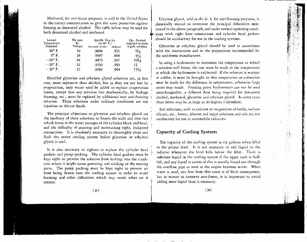
Methanol, for ami-freeze purposes, is sold in the United States in the correct concentration to give the same protection against freezing as denatured alcohol. The table below may be used for both denatured alcohol and methanol.
Lowest Temperature
Expected
10° F. 0°F.
—10° F. —20° F. —30° F.
Per cent by
Volume
30 38 45 51 57
Specific G (at60c
Denatured Alcohol
.9668
.9567
.9475
.9350
.9260
ravity F.) '
Methanol
.972
.964 •957 .950 .944
Qts. Alcohol required to make 6 gals, solution
7M 9¼
10¾ 12 13¾
Distilled glycerine and ethylene glycol solutions are, in first cost, more expensive than alcohol, but as they are not lost by evaporation, only water need be added to replace evaporation losses, except that any solution lost mechanically, by leakage foaming, etc., must be replaced by additional new anti-freezing solution. These solutions under ordinary conditions are not injurious to the car finish.
The principal objections to glycerine and ethylene glycol are the tendency of these solutions to loosen the scale and iron rust which forms in the water passages of the cylinder block and head, and the difficulty of securing and maintaining tight, leakproof connections. It is absolutely necessary to thoroughly clean and flush the entire cooling system before glycerine or ethylene glycol is used.
It is also necessary to tighten or replace the cylinder head gaskets and pump packing. The cylinder head gaskets must be kept t ight to prevent the solution from leaking into the crank-case where it might cause gumming and sticking of the moving parts. The pump packing must be kept t ight to prevent air from being drawn into the cooling system in order to avoid foaming and other difficulties which may result when air is present.
[3S]
Ethylene glycol, sold in the U. S. for anti-freezing purposes, is
chemically treated to overcome the principal difficulties men
tioned in the above paragraph, and under normal operating condi
tions wi th tight hose connections and cylinder head gaskets
should be satisfactory for use in the cooling systems.
Glycerine or ethylene glycol should be used in accordance with the instructions and in the proportions recommended by the anti-freeze manufacturer.
In using a hydrometer to determine the temperature at which a solution will freeze, the test must be made at the temperature at which the hydrometer is calibrated. If the solution is warmer or colder, it must be brought to this temperature or correction must be made for the difference in temperature, otherwise large errors may result. Freezing point hydrometers can not be used interchangeably, a different float being required for denatured alcohol, methanol, glycerine and ethylene glycol. In some cases these errors may be as large as 30 degrees Fahrenheit.
Salt solutions, such as calcium or magnesium chloride, sodium silicate, etc., honey, glucose and sugar solutions and oils are not satisfactory for use in automobile radiators.
Capacity of Cooling System
The capacity of the cooling system is six gallons when filled
to the proper level. It is not necessary to add liquid to the
radiator whenever the level falls below the filler. There is
sufficient liquid in the cooling system if the upper tank is half-
full, and any liquid in excess of this is usually forced out through
the overflow pipe as soon as the engine becomes warm. When
water is used, any loss from this cause is of little consequence,
but in winter to conserve anti-freeze, it is important to avoid
adding more liquid than is necessary.
[39]
Winter Lubrication
Lubrication of the car requires special attention in winter, not only to insure proper lubrication of the moving parts, but to secure the same ease of operation in starting, steering and shifting gears as during warm weather.
The chart of engine oil recommendations on page 33 gives the proper grade of oil to be used for cold weather driving. It will be noted that lighter oils can be used for cold weather providing no prolonged high speed driving is done. For prolonged high speed driving, "Heavy duty" oils must be used. Authorized Cadillac-La Salle Service Stations are prepared with full information on winter lubrication.
The lubricant in the transmission and rear axle should be thinned with kerosene as soon as the weather is so cold that the transmission gears are hard to shift. If a sufficient amount of kerosene is added to provide for the lowest winter temperature expected, it will not be necessary to add kerosene again thereafter during the winter. If ten per cent (a little over half a pint) kerosene is added, this will take care of temperatures down to ten below zero.
There are several lubricants on the market which have a low enough pour point so that they will not require thinning. See an authorized Cadillac-La Salle Service Station for information on these lubricants. If one has been regularly used, no kerosene should be added. Thinning of such a lubricant is not only unnecessary, but defeats the purpose of using it because it would have to be drained and replaced on return of warm weather.
Steering gear lubricant, in any case, should not be thinned as the pressure between the worm and sector will force out the thinned lubricant, resulting in excessive wear. A lubricant of low enough cold test so as not to require thinning should be used.
[40]
Storage Battery
The electrical system of an automobile has much more to do in winter than in summer. The engine is harder to crank and must usually be cranked longer before it starts. The lights are also used to much greater extent than during the long days of summer. AJ1 this means that the battery must be ready for increased demands.
It is therefore a good plan in preparing for the winter season to see that the battery is fully charged, that the battery connections are clean and tight, and that the charging rate is sufficient to take care of the requirements of the system.
Gasoline System
The carburetor on the Cadillac engine has automatic compensation for temperature. Nevertheless it is a good plan to have the carburetor adjustment checked when cold weather arrives. This inspection should give special attention to the carburetor choke control to make sure that the enriching device is fully effective when the choke button is operated.
In warm weather, a small amount of water in the gasoline has little or no effect on the running of the engine. In freezing weather, however, even a small amount of water may freeze and stop the entire flow of fuel to the carburetor. One of the things to be done in preparing for winter weather, therefore, is to clean the gasoline filter and the sediment chambers in the gasoline system.
Starting the Engine
Choke But ton
The first difference between starting the engine in cold weather and starting the engine in warm weather is in the greater use of the choke necessary in cold weather. Gasoline does not vaporize
[41]
as readily at low temperatures, and in order to supply the cylinders with a gaseous mixture rich enough to be ignited, the proportion of liquid gasoline to air must be increased.
At the same time, it is important not to apply the choke more than is necessary. The unvaporized gasoline collects on the cylinder walls and works down past the pistons, washing off the lubricant as it goes. Although dilution of the oil supply with this unburned gasoline is minimized by the crankcase ventilating system, it is best to avoid an excess of liquid gasoline in the combustion chambers by careful and judicious use of the choke.
The following rule should govern the use of the choke in winter weather: Pull the choke back just as far as it is necessary to start the engine, but as soon as the engine starts, return the button as far as possible without causing the engine to stop or slow down. Then push the button all the way in as soon as the engine is warm enough to permit doing so.
Priming the Carburetor
In extremely cold weather, if the engine does not start after cranking for a few seconds with the choke button fully applied, release the starter pedal. Then prime the carburetor by opening and closing the throttle once or twice rather rapidly with the accelerator. Opening and closing the throttle operates a throttle pump on the carburetor and raises the level of the gasoline in the carburetor. The carburetor should never be primed in warm weather and should not be primed unnecessarily in cold weather. Excessive priming is likely to make starting difficult rather than easy.
Position of Throt t le Hand Lever
The correct position of the throttle hand lever for starting in cold weather is the same as for starting under other conditions, that is, about one-fourth the way down from the idling position.
[42]
In warm weather, however, the lever may be returned to the idling position almost as soon as the engine is started. In cold weather the throttle must be left slightly open until the engine becomes warm.
Position of Spark Control
It is the practice of some drivers to retard the spark all the way whenever starting the engine. This is the correct position if the engine is to be cranked by hand, but if the engine is to be cranked with the starter, the spark button should be left all the way in or in the fully advanced position.
Use of Starter
In extremely cold weather, when the car has been standing long enough to become thoroughly chilled, it is a good plan to disengage the clutch during the cranking operation. If this is not done, the starter is called upon to turn the jackshaft gears in the transmission in addition to cranking the engine. At ordinary temperatures, the additional energy required is negligible, but in extremely cold weather, the lubricant in the transmission offers sufficient resistance to rotation of the transmission gears to increase considerably the demand upon the battery and to retard the cranking speed.
Use of Accelerator Before Engine Is Warm
In cold weather, after the engine has been started and before it has run long enough to become warm, the engine cannot deliver its normal power, and it should not be called upon to do so. In accelerating the engine to start the car and in accelerating the car after the transmission is in gear, do not open the throttle suddenly or too far. To do so is not only to invite "popping back" in the carburetor, but to increase the amount of excess unvaporized gasoline in the combustion chambers, both of which results are undesirable.
[ 4 3 ]
CHAPTER VI i
GENERAL CARE
No attempt has been made to include in this manual directions for making adjustments or repairs to the car. Most
Cadillac owners prefer to depend for such work on authorized Cadillac-La Salle service stations, as these stations can invariably perform the work more conveniently and economically.
Every owner should, however, know how to perform the few simple operations of general care described in this chapter. These operations are not difficult enough to necessitate a visit to the service station, although this work can also be done in the service station, if desired.
Storage Battery The storage battery is attached to the right-hand side bar of
the frame under the front seat. It is accessible after removing the seat cushion and cover plate.
The battery is filled with an acid solution from which the water slowly evaporates, and fresh distilled water must be added to each of the three cells at regular intervals to bring the level up to the bottom of the filling tubes. Distilled water should be added at least every 1000 miles, and in warm weather, every 500 miles, or at least every two weeks. If distilled water is not available, melted artificial ice or rain water caught in an earthenware receptacle may be used. Hydrant water or water that has been in contact with metallic surfaces will cause trouble if used. Acid must never be added to the battery.
Important: "Dope" or "rejuvenator" solutions frequently advertised are harmful to the battery and should never be used.
[44]
All battery service, other than the addition of distilled water when necessary, should be performed by an experienced and reliable battery man.
After adding water to the storage battery in freezing weather, the car should immediately be run far enough to mix the water and acid solution thoroughly. If the car is parked immediately after adding water, the water is likely to stay on top of the acid solution and may freeze, causing extensive damage.
As the storage battery is charged and discharged, the solution reacts chemically with the plates of the battery, the specific gravity of the solution changing as the reaction proceeds. The state of charge of the battery is thus indicated by the specific gravity of the solution. As the battery is charged, the specific gravity of the solution increases, reaching 1.270 to 1.285 when the battery is fully charged. The specific gravity of the solution decreases as the battery is discharged. A fully discharged battery has a specific gravity of 1.150 to 1.165.
A hydrometer is the instrument used to measure the specific gravity of a solution. A hydrometer syringe is a hydrometer especially designed for convenience in testing the specific gravity of the acid solution in the storage battery. A hydrometer syringe can be obtained at any battery service station. Be sure and get a reliable instrument, for cheap ones may be in error as much as 25 or 30 points.
The specific gravity of the acid solution should never be tested immediately after adding distilled water. If the solution is below the plates, so that it cannot be reached with the syringe, add the necessary amount of water, then drive the car for a few hours before taking the hydrometer reading.
The battery is a Delco battery, made by the Delco-Remy Corporation, Anderson, Indiana. If the storage battery is in need of attention other than recharging, it should always be taken to an authorized Cadillac service station or to a United Motors service station.
["5]
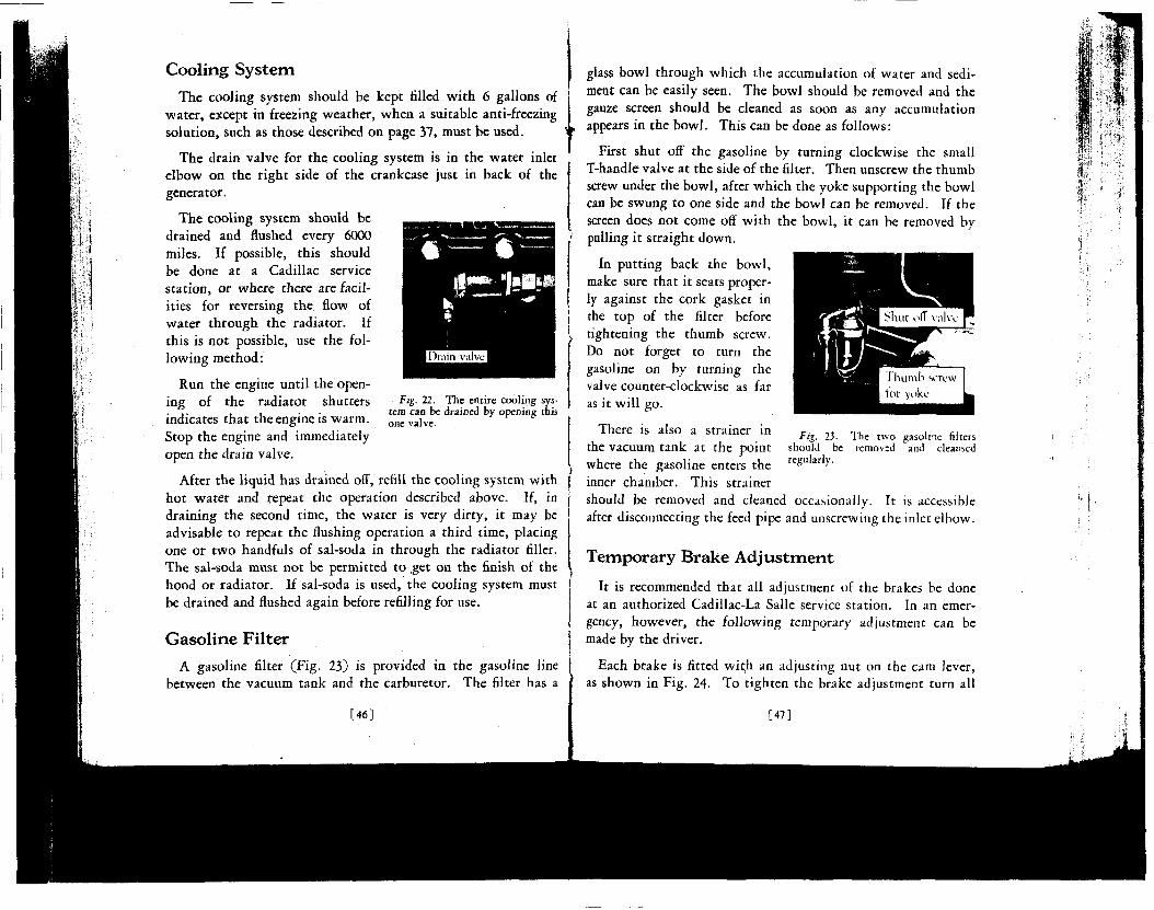
Cooling System
The cooling system should be kept filled with 6 gallons of water, except in freezing weather, when a suitable anti-freezing solution, such as those described on page 37, must be used.
The drain valve for the cooling system is in the water inlet elbow on the right side of the crankcase just in back of the generator.
The cooling system should be drained and flushed every 6000 miles. If possible, this should be done at a Cadillac service station, or where there are facilities for reversing the flow of water through the radiator. If this is not possible, use the following method:
Run the engine until the opening of the radiator shutters indicates that the engine is warm. Stop the engine and immediately open the drain valve.
After the liquid has drained off, refill the cooling system with hot water and repeat the operation described above. If, in draining the second time, the water is very dirty, it may be advisable to repeat the flushing operation a third time, placing one or two handfuls of sal-soda in through the radiator filler. The sal-soda must not be permitted to get on the finish of the hood or radiator. If sal-soda is used, the cooling system must be drained and flushed again before refilling for use.
Gasoline Filter
Fig. 22. The entire cooling system can be drained by opening this one valve.
A gasoline filter (Fig. 23) is provided in the gasoline line between the vacuum tank and the carburetor. The filter has a
[46]
glass bowl through which the accumulation of water and sediment can be easily seen. The bowl should be removed and the gauze screen should be cleaned as soon as any accumulation appears in the bowl. This can be done as follows:
First shut off the gasoline by turning clockwise the small T-handle valve at the side of the filter. Then unscrew the thumb screw under the bowl, after which the yoke supporting the bowl can be swung to one side and the bowl can be removed. If the screen does not come off with the bowl, it can be removed by pulling it straight down.
In putting back the bowl, make sure that it seats properly against the cork gasket in the top of the filter before tightening the thumb screw. Do not forget to turn the gasoline on by turning the valve counter-clockwise as far as it will go.
There is also a strainer in c . ,, T, ,• ,-, tig. 23. Ine two gasoline niters
the vacuum t a n k a t t he p o i n t should be removed and cleansed where the gasoline enters the rcgu y" inner chamber. This strainer should be removed and cleaned occasionally. It is accessible after disconnecting the feed pipe and unscrewing the inlet elbow.
Temporary Brake Adjustment
It is recommended that all adjustment of the brakes be done at an authorized Cadillac-La Salle service station. In an emergency, however, the following temporary adjustment can be made by the driver.
Each brake is fitted with an adjusting nut on the cam lever, as shown in Fig. 24. To tighten the brake adjustment turn all
[47]

four adjusting nuts half a turn clockwise. These adjusting nuts lock each sixth of a turn.
Fig. 24. A temporary brake adjustment can be secured by turning the adjusting nut on each brake clockwise one-half turn. The front brake is shown above at the left, the rear brake at the right.
Body
Care of Finish
The lacquer finish of Cadillac bodies can be kept new and lustrous with the simplest care. The car should merely be wiped off every few days with a soft dry cloth. An occasional polishing with some recognized lacquer polish (for sale by all Cadillac distributors and dealers) will prove beneficial.
If the finish receives this attention at regular intervals, it will not need to be washed, except when it has accumulated a considerable amount of mud or dust. When washing the car, use plenty of clean cold water. Do not use hot water, and do not wash the hood while it is hot, as this will in time destroy the luster. Do not use soap.
If a hose is used in washing, do not use a nozzle, but let the water flow gently from the hose and flush off the dirt gradually. A soft wool sponge can be used to advantage in removing dirt.
After the washing is completed, squeeze the sponge as dry as possible and pick up all water from crevices. Then thoroughly
[48]
wet a clean soft chamois, wring it as dry as possible and dry the finish. The finish can then be rubbed with a clean soft cloth to bring out the luster.
Care of the Top
Ordinary dust can be removed from the top with a soft dry cloth. Grease spots, stains and dirt film can be removed by washing with a mild, neutral soap. Rinse thoroughly with clear water to remove all traces of the soap, then dry with a chamois or cloth. Gasoline, naphtha, kerosene and fabric cleaners should not be used for cleaning the top, as such preparations are likely to dull the luster and damage the fabric, causing leaks.
Cleaning Upholstery
To keep the upholstery in closed cars in the best condition, it should be cleaned thoroughly at least once a month with a whisk broom and vacuum cleaner. Dirt and grit accumulating in the fabric wear it out faster than use.
Spots on the upholstery may be cleaned with any good dry cleaner but care should be taken not to apply too much. The use of too much or too strong a cleaner may dissolve the rubber backing of plush upholstery, causing the nap to loosen. When the cleaner has thoroughly evaporated, apply a hot flatiron wrapped in a wet cloth. Steaming the fabric and rubbing lightly against the nap will raise the nap on plush fabrics to its normal position.
Door Hardware
Many owners who give careful attention to lubrication of the chassis do not give the same attention to the lubrication of door locks and hinges. If the door hardware is to operate properly, it must be lubricated regularly. Directions for this lubrication are included in the lubrication chart, and these directions should be followed as faithfully as the rest of the chart.
[491
CHAPTER VII
STORING CAR
Ip THE car is not to be used for a period of several months, it should be protected from deterioration during the period
when it is not in use by carefully preparing it for storage.
Engine
To prepare the engine for storage, proceed as follows: Run the engine until opening of the radiator shutters indicates that the engine is warm. This may be done by driving on the road or by running the engine idle. In the latter case, care should be taken that there is sufficient ventilation to avoid personal injury from carbon monoxide poisoning. (See page 19). After the engine is warm, place the car where it is to be stored and stop the engine.
Remove the spark plugs. Inject two or three tablespoonfuls of engine oil into each spark plug hole, and before replacing the plugs, crank the engine three or four revolutions with the ignition switched off. This will tend to distribute the oil over the cylinder walls. The engine should not be started again after injecting the oil. If it is started, it will be necessary to repeat the treatment.
Drain the cooling system.
Storage Battery
If the car is to be stored during the winter, the storage battery should have special treatment in order to protect it against freezing.
Shortly before the car is used for the last time, distilled water should be added to bring the level of the solution up to the
[50]
\
bottom of the filling tubes. (See page 44.) After the water added has had an opportunity to mix thoroughly with the acid solution by running the car or engine, the specific gravity should be tested with a hydrometer. If the specific gravity of the solution is above 1.270, there will be no danger of the acid solution freezing. If, however, the specific gravity is below 1.270, the battery should be removed and charged. Unless the battery is fully charged, or nearly so, it is probable that the acid solution will freeze and cause extensive damage.
The battery ground connection should in all cases be disconnected during storage, as a slight leak in the wiring will discharge the battery and lower the specific gravity to the point where the solution may freeze.
If possible, the storage battery should be removed and charged from an outside source every two months during the storage period.
Tires
During the storage of the car, it is best to remove the tires from the rims and to keep the casings and tubes in a fairly warm atmosphere away from the light. The tubes should be inflated slightly after the tires have been removed.
If it is not convenient to remove the tires from the car, and the car is stored in a light place, cover the tires to protect them from strong light, which has a deteriorating effect on rubber.
The weight of the car should not be allowed to rest on tires during the storage period. If tires are not removed, the car should be blocked up, so that no weight is borne by the tires. The tires should also be partly deflated.
Body and Top
A cover should be placed over the entire car to protect it J from dust. In storing an open car, the top should be up.
h i ]
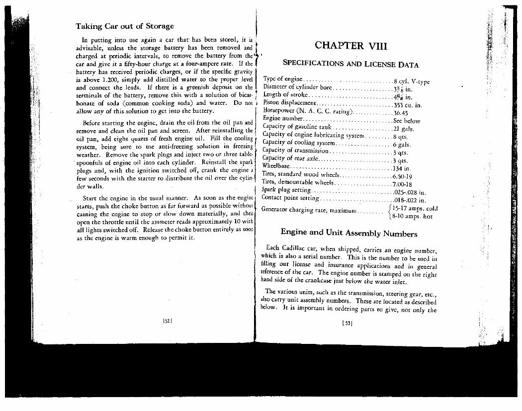
Taking Car out of Storage
In putting into use again a car that has been stored, it is advisable, unless the storage battery has been removed and charged at periodic intervals, to remove the battery from the'^ car and give it a fifty-hour charge at a four-ampere rate. If the battery has received periodic charges, or if the specific gravity is above 1.200, simply add distilled water to the proper level and connect the leads. If there is a greenish deposit on the terminals of the battery, remove this with a solution of bicarbonate of soda (common cooking soda) and water. Do not allow any oi this solution to get into the battery.
Before starting the engine, drain the oil from the oil pan and remove and clean the oil pan and screen. After reinstalling the oil pan, add eight quarts of fresh engine oil. Fill the cooling system, being sure to use anti-freezing solution in freezing weather. Remove the spark plugs and inject two or three table-1 spoonfuls of engine oil into each cylinder. Reinstall the spark plugs and, with the ignition switched off, crank the engine a few seconds with the starter to distribute the oil over the cylinder walls.
Start the engine in the usual manner. As soon as the engine starts, push the choke button as far forward as possible without causing the engine to stop or slow down materially, and then open the throttle until the ammeter reads approximately 10 with all lights switched off. Release the choke button entirely as soon as the engine is warm enough to permit it.
I52|
CHAPTER VIII
SPECIFICATIONS AND LICENSE DATA
Type of engine 8 cyi. V-type Diameter of cylinder bore 3¾ in. Length of stroke 4¾ in. Piston displacement 353 cu. in. Horsepower (N. A. C. C. rating) 36.45 Engine number. See below Capacity of gasoline tank 21 gals. Capacity of engine lubricating system 8 qts. Capacity of cooling system 6 gals. Capacity of transmission 3 qts. Capacity oi rear axle 3 qts. Wheelbase 134 in. Tires, standard wood wheels 6.50-19 Tires, demountable wheels 700-18 Spark plug setting 025-028 in. Contact point setting 018-.022 in. „ , /15-17 amps, cold Generator charging rate, maximum S „ ,„ ,
& & (8-10 amps, hot
Engine and Unit Assembly Numbers
Each Cadillac car, when shipped, carries an engine number, which is also a serial number. This is the number to be used in filling out license and insurance applications and in general reference of the car. The engine number is stamped on the right hand side of the crankcase just below the water inlet.
The various units, such as the transmission, steering gear, etc., also carry unit assembly numbers. These are located as described below. It is important in ordering parts to give, not only the
[53]
y $-3
i,

engine number of the car, but also the unit assembly number of the unit to which the part belongs.
Transmission number—on the upper left-hand edge of the flange by which the transmission is bolted to the crankcase.
Steering gear number—on the steering gear housing next to the grease plug
Generator number—oa the right-hand side of the generator.
Starting motor number—on the right-hand side of the starter, just below the switch.
Front axle number—on the upper surface of the right-hand spring pad, just outside of the car spring.
Rear axle number—on the rear surface of the axle housing just to j the right of the cover plate. f
Chassis (Jrame) number—on the flange of the first channel cross- | member, next to the left front engine support. [
154]
I N D E X
1 Accelerator 9 Accelerator, use in cold weather. . . .43 Adding water to battery 44 Adjustable seats 22 Alcohol for anti-freeze 37 Ammeter 14 Anti-freeze solutions 37 Authorized service stations 3
B
Balancing marks on tires 26 Battery 44 Battery, preparing for storage 50 Brake adjustment 47 Brakes 18
Effect of Alcohol on finish 37 Engine fails to start 13 Engine lubrication 34 Engine number 53 Engine oil 32 Engine oil, changing 35 Engine oil, thinning 40 Engine, preparing for storage 50 Engine, running in garage 19 Equipment 21
Filter for gasoline 46 Filter for oil 35 Flat-rate service charges 5 Flooded carburetor 13 Flushing cooling system 46 Foot brakes 18
Cadillac service 3 Carbon monoxide poisoning 19 Carburetor flooded 13 Carburetor, to prime 42 Card, service 4 Changing engine oil 35 Changing ttres 25 Charging rate 14, 50 Charges for service 5 Chart, lubrication 31 Chassis grease 33 Choke button 10
&^:::::::::::::::::::::8 ^^-Clutch, use of 15 Coasting 17 Coincidental lock 8 Cold weather lubrication 40 Cold weather operation 37 Compartment for tools 23 Contract, Service 5 Cooling system 37, 46 Crankcase ventilating system 35
Gasoline filter 46 Gasoline gauge 9 Gasoline system, cold weather 41 Gear lubricant 33 General care 44 Glycerine for anti-freeze 38 Greases 31
H
I
Ignition control 11, 43 Ignition switch lock 8 Inflation pressure 23 Inspections 7
D J
Jack, use of 25
Danger from carbon monoxide 19 Driver's seat adjustment 22 Driving speed when new 6 Keys.
155]
K
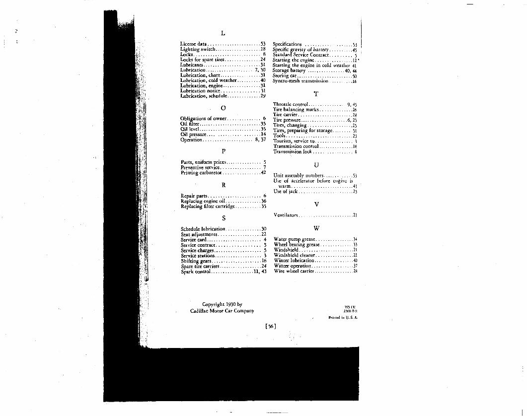
L License data 53 Lighting switch 18 Locks 8 Locks for spare tires 24 Lubricants 31 Lubrication 7, 30 Lubrication, chart 31 Lubrication, cold weather 40 Lubrication, engine 31 Lubrication notice 31 Lubrication, schedule 29
o Obligations of owner 6 Oil filter 35 Oil level 35 Oil pressure 14 Operation 8, 37
P
Parts, uniform prices 5 Preventive service 7 Priming carburetor 42
R
Repair parts 6 Replacing engine oil 36 Replacing filter cartridge 35
S
Schedule lubrication 30 Seat adjustments 22 Service card 4 Service contract 5 Service charges 5 Service stations 3 Shifting gears 16 Spare tire carriers 24 Spark control 11, 43
Specifications 53 Specific gravity of battery 45 Standard Service Contract 5 Starting the engine 12' Starting the engine in cold weather 41 Storage battery 40, 44 Storing car 50 Syncro-mesh transmission 16
T Throttle control 9, 43 Tire balancing marks 26 Tire carrier 24 Tire pressure 6, 23 Tires, changing 25 Tires, preparing for storage 51 Tools 23 Tourists, service to 3 Transmission control 16 Transmission lock 8
U
Unit assembly numbers 53 Use of accelerator before engine is
warm 43 Use of jack 25
Ventilators 21
w Water pump grease 34 Wheel bearing grease 33 Windshield 21 Windshield cleaner 22 Winter lubrication 40 Winter operation 37 Wire wheel carrier 24
Copyright 1930 by Cadillac Motor Car Company
»5-1» 2300-801
[56]
Printed in U. S. A.
/ , f i /
¥ PRELIMINARY
SERVICE INFORMATION
Cadillac 355 La Salle 345
i'^f] /^ / ' " "7" ("i *""•?<* ft* S ;
September, 1930
U-'L-'7"7
*iQ HOT KZMQVb Ui
Service Department
CADILLAC MOTOR CAR COMPANY
DETROIT, MICHIGAN

CONTENTS
Puqe
Axles 3
Body 4
Brakes - 5
Clutch ... - 6
Cooling System 6
Electrical ..... 7 Battery 7 Generator .... — 7 Horns —. 7 Ignition — 7 Starting Motor 7 Wiring 8 W/nng Diagram 9
Engine - 8 Exhaust System — 10
Frame — 10 Gasoline System .... .... . — 10
Intake Muffler 10 Carburetor 11
Lighting System — 11
Springs 1 1 Shock Absorbers 12
Steering Gear — — 12 Adjustments . 13 Steering Connecting Rod 14
Transmission 1'5 Speedometer Drive 15
Wheels - . .... - 15 Tire Sizes .. 15
Copyright, 1930 Cadillac Motor Car Co-
Detroit, Mich., U. S. A.
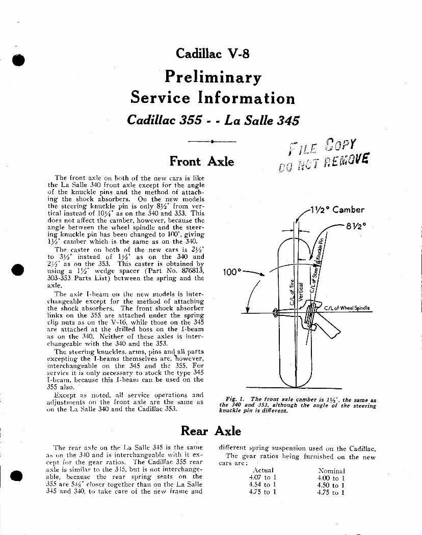
Cadillac V-8
Preliminary Service Information
Cadillac 355 - - La Salle 345
Front Axle GOPY I, I / ..
,. r.r,T ngiSQVE
The front axle on both of the new cars is like the La Salle 340 front axle except for the angle of the knuckle pins and the method of attaching the shock absorbers. On the new models the steering knuckle pin is only 8^° from vertical instead of 10¾° as on the 340 and 353. This does not affect the camber, however, because the angle between the wheel spindle and the steering knuckle pin has been changed to 100°, giving 1½° camber which is the same as on the 340.
The caster on both of the new cars is 2y2° to 2>y2° instead of \y2 as on the 340 and 2y2° as on the 353. This caster is obtained by using a 1½° wedge spacer (Par t No. 876813, 303-353 Parts List) between the spring and the axle.
The axle I-beam on the new models is interchangeable except for the method of attaching the shock absorbers. The front shock absorber links on the 355 are attached under the spring clip nuts as on the V-16, while those on the 345 are attached at the drilled boss on the I-beam as on the 340. Neither of these axles is interchangeable with the 340 and the 353.
The steering knuckles, arms, pins and all par ts excepting the I-beams themselves are, "however, interchangeable on the 345 and the 355. For service it is only necessary to stock the type 345 I-beam, because this I-beam can be used on the 355 also.
Except as noted, all service operations and adjustments on the front axle are the same as on the La Salle 340 and the Cadillac 353.
11/2° Camber
8 ½ °
C/LoF Wheel Spindle
Fig. 1. The front axle camber is iy2", the same as the 340 and 353, although the angle of the steering knuckle pin is different.
Rear Axle The rear axle on the La Salle 345 is the same
as on the 340 and is interchangeable with it except for the gear ratios. The Cadillac 355 rear axle is similar to the 345, but is not interchangeable, because the rear spring seats on the 355 are 5V$" closer together than on the La Salle 345 and 340, to take care of the new frame and
different spring suspension used on the Cadillac, being furnished on the new The gear ratios
cars are : Actual
4.07 to 1 4.54 to 1 4.75 to 1
Nominal 4.00 to 1 4.50 to 1 4.75 to 1
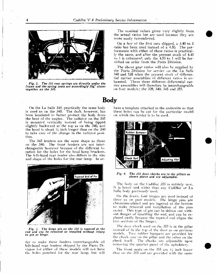
Cadillac V-8 Preliminary Service Information
Fig. 2. The 355 rear springs are directly under the frame and the spring seats are accordingly 5¥a" closer together on the 345.
The nominal values given vary slightly from the actual ratios but are used because they are more easily remembered.
On a few of the first cars shipped, a 4.40 to 1 ratio has been used instead of a 4.50. The performance with either of these ratios is practically the same, and after the present stock of 4.40 to 1 is exhausted, only the 4.50 to 1 will be furnished on order from the Parts Division.
The above gear ratios will also be supplied by the Par ts Division for service on the. La Salle 340 and 328 when the present stock of differential carrier assemblies of different ratios is exhausted. These three different differential carrier assemblies will therefore be interchangeable on four models; the 328, 340, 345 and 355.
Body On the La Salle 345, practically the same body
is used as on the 340. The dash, however, has been insulated to better protect the body from the heat of the engine. The radiator on the 345 is mounted vertically instead of being tipped slightly backward at the top as on the 340, and the hood is about Yi inch longer than on the 340 to take care of the change in the radiator position.
The 345 fenders are the same shape as those on the 340. The front fenders are not interchangeable however because of the different location for the holes for the head lamp brackets. The left-hand rear fender also differs in the size and shape of the holes for the rear lamp. In or-
Fig. 3. The hinge pin on the 355 is tapered at the end and can be removed or installed without injury to pin or hinge.
(lev to make these fenders interchangeable all left-hand rear lenders shipped by the Parts Division for either of these models will not have the holes punched for the rear lain]), but will
have a template attached to the underside so that these holes can be cut for the particular model on which the fender is to be used.
Fig. 4. The 355 door checks are in the pillars as shown above and are adjustable.
The body on the Cadillac 355 is entirely new. It is lower and wider than any Cadillac or La Salle body previously used.
On the doors, four hinges are used instead of three as on past models. The hinge pins are chromium-plated and are tapered at the bottom to make removal and installation of the pins easier. This type of pin can be driven out without danger of upsetting the end, and can be replaced easily because the tapered end aligns the two sections of the hinges.
The door cluck used on the 355 is in the pillar instead ol in the top of the door as on previous models. Two rubber bumpers are provided for the check, one on the pillar and the other on the check itself. The checks are adjustable upon removing the quarter panel of the upholstery.
The front seats on the 355 are *4 inch lower than on the ,^5.^ and are provided with the same
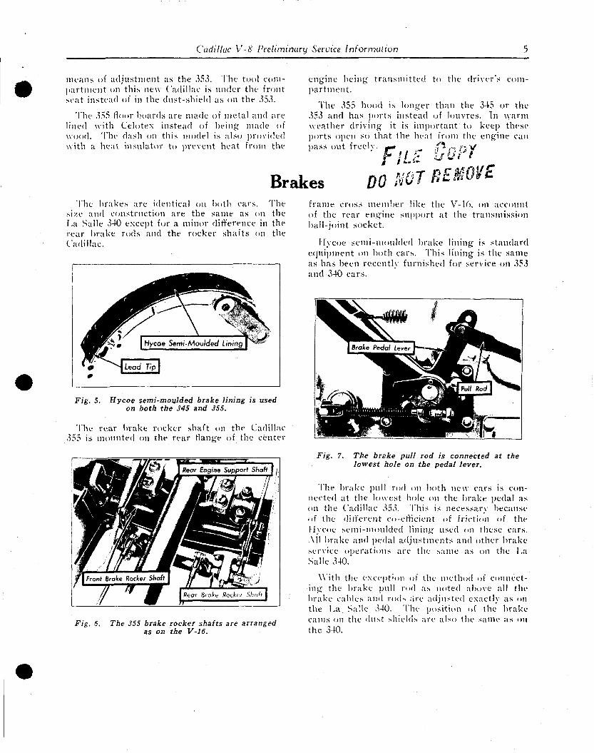
Cadillac V-8 Preliminary Service Information 5
means of adjustment as the 353. The tool compartment on this new Cadillac is under the front seat instead of in the dust-shield as on the 353.
The 355 floor boards are made of metal and are lined with Celotex instead of being; made of wood. The dash on this model is also provided with a heat insulator to prevent heat from the
engine being transmitted to the driver's compartment.
The 355 hood is longer than the 345 or the 353 and has ports instead of louvres. In warm weather driving it is important to keep these ports open so that the heat from the engine can pass out freeL
ILL •:t ** .-uopr
Brakes DO NOT REMV£ The brakes are identical on both cars. The
size and construction are the same as on the La Salle 340 except for a minor difference in the rear brake rods and the rocker shafts on the Cadillac.
Fig. 5. Hycoe semi-moulded brake lining is used on both the 345 and 355.
The rear brake rocker shaft on the Cadillac 355 is mounted on the rear flange of the center
r Engine Support Shafi [ f,
frame cross member like the V-16, on account of the rear engine support at the transmission ball-joint socket.
Hycoe semi-moulded brake lining is standard equipment on both cars. This lining is the same as has been recently furnished for service on 353 and 340 cars.
Fig. 6. The 355 brake rocker shafts are arranged as on the V-16.
Fig. 7. The brake pull rod is connected at the lowest hole on the pedal lever.
The brake pull rod on both new cars is connected at the lowest hole on the brake pedal as on the Cadillac 353. This is necessarv because of the different co-efficient of friction of the Hycoe semi-moulded lining used on these cars. All brake and pedal adjustments and other brake service operations are the same as on the I .a Salle 340.
With the exception of the method of connecting the brake pull rod as noted above all the brake cables and rods are adjusted exactly as on the La Salle 340. The position of the brake cams on the dust shields are also the same as on the 340.
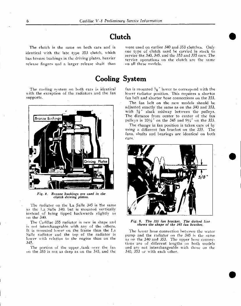
6 Cadillac V-8 Preliminary Service Information
Clutch The clutch is the same on both cars and is
identical with the late type 353 clutch, which
has bronze bushings in the driving plates, heavier
release fingers and a larger release shaft than
were used on earlier 340 and 353 clutches. Only one type of clutch need be carried in stock to service the 340, 345, and the 353 and 355 cars. The service operations on the clutch are the same on all these models.
Cooling System The cooling system on both cars is identical
with the exception of the radiators and the fan supports.
Fig. 8. Bronze bushings are used in the clutch driving plates.
The radiator on the La Salle 345 is the same as the La Salle 340, but is mounted vertically instead of being tipped backwards slightly as on the 340.
The Cadillac 355 radiator is new in shape and is not interchangeable with any of the others, (t is mounted lower on the frame than the La Salle radiator and the top of the radiator is lower with relation to the engine than on the 345.
The portion of the upper . tank over the fan on the 355 is not as deep as on the 345, and the
fan is mounted %" lower to correspond with the lower radiator position. This requires a shorter fan belt and shorter hose connections on the 355.
The fan belt on the new models should be adjusted exactly the same as on the 340 and 353, with Y&" slack midway between the pulleys. The distance from center to center of the fan pulleys is 10½" on the 345 and 9y/ on the 355.
The change in fan position is taken care of bousing a different fan bracket on the 355. The fans, shafts and bearings are identical on both cars.
Fig. 9. The 355 fan bracket. The dotted line shows the shape of the 345 fan bracket.
The lower hose connection between the water pump and the radiator on the 345 is the same as on the 340 and 353. The upper hose connections are of different lengths on both models and are not interchangeable with those on the 340, 353 or with each other.
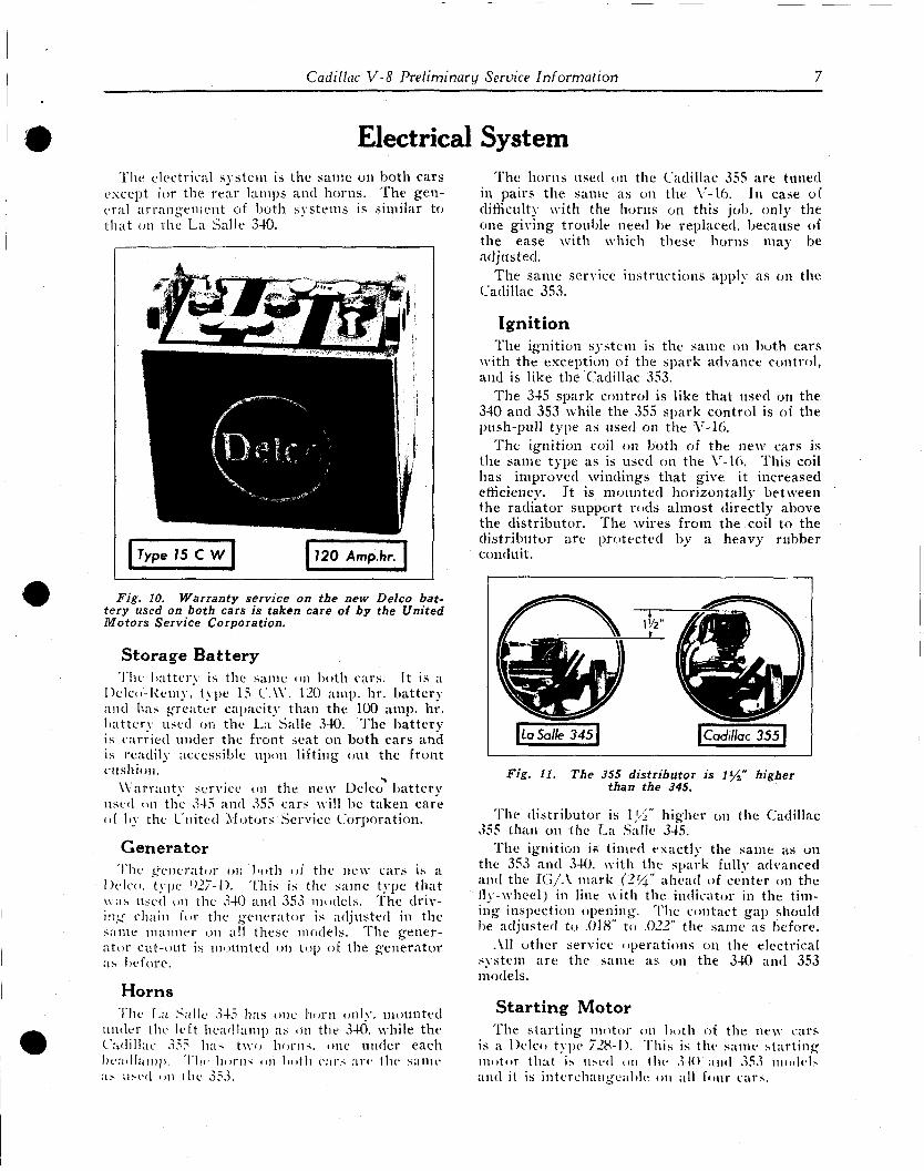
Cadillac V-8 Preliminary Service Information 7
Electrical System The electrical system is the same on both cars
except for the rear lamps and horns. The general arrangement of both systems is similar to that on the La Salle 340.
Fig. 10. Warranty service on the new Delco battery used on both cars is taken care of by the United Motors Service Corporation.
Storage Battery The battery is the same on both cars. It is a
Dclco-Remv, type 15 CAY. 120 amp. hr. battery and has greater capacity than the 100 amp. hr. battery used on the La Salle 340. The battery is carried under the front seat on both cars and is readily accessible upon lifting out the front cushion.
Warrant}' service on the new Delco battery used on the 345 and 355 cars will be taken care of by the United Motors Service Corporation.
Generator The generator on both of the new cars is a
Delco. type 927-1). This is the same type that was used on the 340 and 353 models. The driving chain for the generator is adjusted in the same manner on all these models. The generator cut-out is mounted on top of the generator as before.
Horns The La Salic 345 has one horn only, mounted
under the left headlamp as on the 340, while the Cadillac 355 ha* two horns, one under each headlamp. The horns on both cars are the same as used on the 353.
The horns used on the Cadillac 355 are tuned in pairs the same as on the V-16. In case of difficult}- with the horns on this job, only the one giving trouble need be replaced, because of the ease with which these horns may be adjusted.
The same service instructions applv as on the Cadillac 353.
Ignition The ignition system is the same on both cars
with the exception of the spark advance control, and is like the Cadillac 353.
The 345 spark control is like that used on the 340 and 353 while the 355 spark control is of the push-pull type as used on the V-16.
The ignition coil on both of the new cars is the same type as is used on the V-16. This coil has improved windings that give it increased efficiency. It is mounted horizontally between the radiator support rods almost directly above the distributor. The wires from the coil to the distributor are protected by a heavy rubber conduit.
Fig. 11. The 355 distributor is iy2" higher than the 345.
The distributor is \]A" higher on the Cadillac 355 than on the La Salle 345.
The ignition is timed exactly the same as on the 353 and 340. with the spark fully advanced and the IG/A mark (2'4" ahead of center on the fly-wheel) in line with the indicator in the timing inspection opening. The contact gap should be adjusted to .018" to .022" the same as before.
All other service operations on the electrical system are the same as on the 340 and 353 models.
Starting Motor The starting motor on both of the new cars
is a Delco type 728-D. This is the same starting motor that is used on the 34<> and 353 model* and it is interchangeable on all four cars.
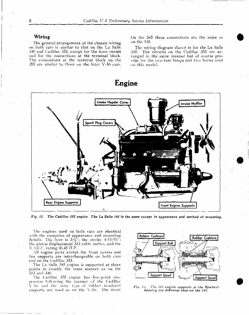
8 Cadillac V-8 Preliminary Service Information
Wiring The general arrangement of the chassis wiring
on both cars is similar to that on the La Salle 340 and Cadillac 353, except for the horn circuit and for the connections at the terminal block. The connections at the terminal block on the 355 are similar to those on the later V-16 cars.
Engine
Fig. 12. The Cadillac 355 engine. The La Salle 345 is the same except in appearance and method of mounting.
The engines used on both cars are identical with the exception of appearance and mounting details. The bore is Z-/&"; the stroke 4-15/16"; the piston displacement 353 cubic inches, and the X.A.C.C. rating 36.45 H.P.
All engine parts except the front covers and fan supports are interchangeable on both cars and on the Cadillac 353.
The La Salle 345 engine is supported at three points in exactly the same manner as on the 353 and 340.
The Cadillac 355 engine has five-point suspension following the manner of the Cadillac Y 1(>. and lln- same l\ pi- of rubber insulated supports are used as on the Y-lo. The front
On the 345 these connections are the same as on the 340.
The wiring diagram shown is for the La Salle 345. The circuits, on the Cadillac 355 are arranged in the same manner but of course provide for the two rear lamps and two horns used on this model.
Fin. I J. The JS5 engine supports at the flywheel housing are different than on the 345.
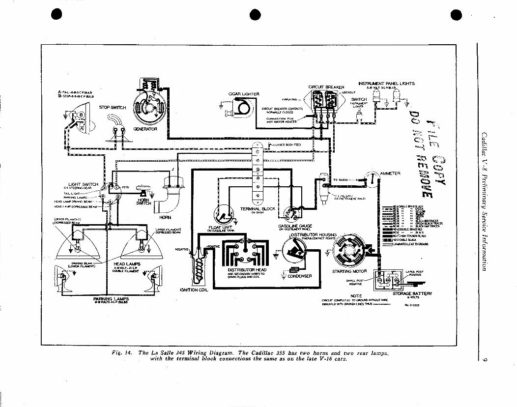
INSTRUMENT PANEL LIGHTS 6-avoLT acpeu j
A-TA IL -6 -6 -3 C P BULS
B-STOP-6-8- IS C P BULB
PARKING LAMPS d-BVOLTSSCP BULBS
NOTE CIRCUIT COMPLETED TO GROUND WITHOUT WWE
INDICATED WITH BROKEN L f C S THUS ™ ™ ~ ~
STORAGE BATTERY 6 VOLTS
Fig. 14. The La Salle 345 Wiring Diagram. The Cadillac 355 has two horns and two rear lamps, with the terminal block connections the same as on the late V-16 cars.

10 Cadillac V-8 Preliminary Service Information
supports at each side of the timing chain cover differ slightly from the Cadillac V-16. Only one through-bolt is used on each side on the Cadillac 355 instead of two as on the V-16. This bolt passes directly through the center of the supporting cone on the motor support bracket and should be tightened in the same manner as on the V-16. by drawing the nut down until there is no more play in the bolt and then tightening the nut exactly one and one-half turns further before putting the cotter pin in place.
The supports at the sides of the flywheel housing are designed differently than on the V-16. because of the greater width of the 355 frame at this point.
The supports at the rear of the transmission on the Cadillac 355 are identical with those on the Cadillac V-16 and are interchangeable with them.
All other service operations are identical with those on the La Salle 340 and Cadillac 353.
''?
" * %%,' - * 'Ih^y mwi jj£f]l JiHHlSr V^^3it4lslL% Jjf^Hi 'mafgL ^*<*&tJ&?Wamim * J G I H F !
&*.>0°k«,**-> • \*
j fe^fc l* " '5*
iftfet Engine
%. \ «11 •/iSw^sifiP'Su Q | ^ m ^ ^ ^ | Front Cover |
wLJ&JRKiJl m
'i?*3 Support brackets \^"^
Fig. 15. The Cadillac 355 engine has a new front cover with an engine support bracket on each side similar to the V-16.
Exhaust System The exhaust system on both cars is the same,
but a new and more effective muffler is used. This muffler has the same dimensions as used on the 340 and 353 and can be used interchangeably
on all four cars. The heat control valve for the intake manifold
is identically the same as on the 340 and 353, and the same service operations apply.
Frame The frame on the La Salle 345 is identically
the same as the frame used on the La Salle 340. The Cadillac 355. however, has an entirely new frame, especially designed for the five point motor support and the new type of spring sus
pension now used on this job. The wheelbase on both models is 134 inches,
the same as the La Salle 340. The side bar section on the Cadillac 355 frame is identically the same as the La Salle 340.
Gasoline System The gasoline system is the same on both cars
and is like that on the 340 except for the use of an intake muffler. The tank on the 345 is exactly the same as the 340 and is interchangeable with it. A new tank of 21 gallons capacity, however, is used on the 355. This tank is not interchangeable with any other.
Intake Muffler The intake muffler silences the roar of the
intake characteristic at certain engine speeds under open throttle. It is mounted on an elbow attached to the bottom of the auxiliary air intake of the carburetor. From the lowest point on this elbow a duct leads to the primary air intake at the bottom of the carburetor.
This intake muffler operates on an entirely new principle. The silencing is not accomplished by baffle plates, but by means of opposing vibrations set up within the muffler itself.
The accompanying sectional view of the intake muffler shows that there is an unrestricted Ilow
fcrr—.
Air Passage to Carburetor
Neutralizing Chamber
Fig. 16. The intake muffler does not affect the carburetor adjustments. They are made exactly as on the 340 and 353 cars.
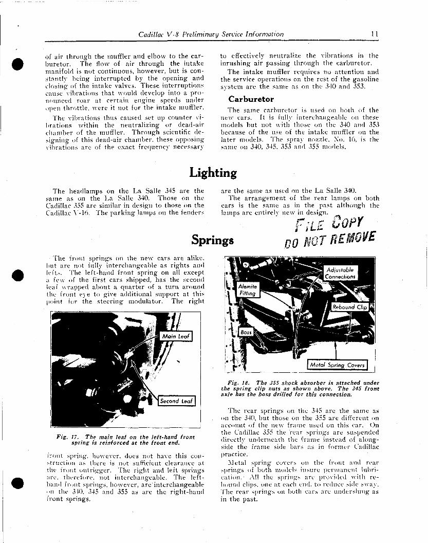
Cadillac V-8 Preliminary Service Information 11
of air through the muffler and elbow to the carburetor. The flow of air through the intake manifold is not continuous, however, but is constantly being interrupted by the opening and closing of the intake valves. These interruptions cause vibrations that would develop into a pronounced roar at certain engine speeds under open throttle, were it not for the intake muffler.
The vibrations thus caused set up counter vibrations within the neutralizing or dead-air chamber of the muffler. Through scientific designing of this dead-air chamber, these opposing vibrations arc of the exact frequency necessary
The front springs on the new cars are alike, but are not fully interchangeable as rights and lefts. The left-hand front spring on all except a few of the first cars shipped, has the second leaf wrapped about a quarter of a turn around the front eye to give additional support at this point for the steering modulator. The right
Fig. 17. The main leaf on the left-hand front spring is reinforced at the front end.
front spring, however, does not have this construction as there is not sufficient clearance at the front outrigger. The right and left springs arc. therefore, not interchangeable. The left-band front springs, however, are'interchangeable "ii the 340. ,345 and 355 as are the right-hand front springs.
to effectively neutralize the vibrations in the inrushing air passing through the carburetor.
The intake muffler requires no attention and the service operations on the rest of the gasoline system are the same as on the 340 and 353.
Carburetor The same carburetor is used on both of the
ntw cars. It is fully interchangeable on these models but not with those on the 340 and 353 because of the use of the intake muffler on the later models. The spray nozzle. No. 16, is the same on 340, 345. 353 and 355 models.
Fig. 18. The 355 shock absorber is attached under the spring clip nuts as shown above. The 345 front axle has the boss drilled for this connection.
The rear springs on the 345 are the same as on the 340, but those on the 355 are different on account of the new frame used on this car. On the Cadillac 355 the rear springs are suspended directly underneath the frame instead of alongside the frame side bars as in former Cadillac practice.
Metal spring covers on the front and rear springs of both models insure permanent lubrication. All the springs are provided with rebound clips, one at each end. to reduce side sway. The rear springs on both cars are underslung as in the past.
Lighting The headlamps on the La Salle 345 are the are the same as used on the La Salle 340.
same as on the La Salle 340. Those on the The arrangement of the rear lamps on both Cadillac 355 are similar in design to those on the cars is the same as in the past although the Cadillac Y-16. The parking lamps on the fenders lamps are entirely new in design.
r* COPY Springs n'o HOT BEHOVE
tit
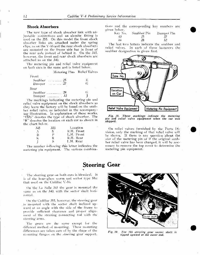
12 Cadillac V-8 Preliminary Service Information
Shock Absorbers T h e new type of shock absorbe r link with ad
jus t ab le connect ions and an a lemi te fitting is used on the 355. On this model the front shock abso rbe r l inks a re a t t a ched under the spring-clips, as on the Y-16 and the rea r shock abso rbe r s a r e m o u n t e d on the f r ame side ba r in front of the r ea r axle ins tead of behind it. On the 345. however , the front and r ea r shock abso rbe r s a re a t t a c h e d as on the 340.
The m e t e r i n g pin and relief valve equ ipment on both cars is the same and is listed below.
M e t e r i n g f i n s Relief Valves
F r o n t Snubber 25 E B u m p e r ...- 27 (>
R e a r Snubber 28 (4 B u m p e r . S2 J
The m a r k i n g s indica t ing the m e t e r i n g pin and relief valve equ ipment on the shock abso rbe r s as they leave the factory will be found on the snubber relief valve, as indicated in the accompanying i l lus t ra t ion . In explana t ion of these m a r k s . "1576" deno tes the type of shock absorber . The " R " deno tes the location on each car as shown in the cha r t below.
345 355 Locat ion A N R.H. F r o n t B P L .H. F r o n t K R R.H. Rea r J S 1..H. R e a r
The n u m b e r fol lowing this l e t t e r indicates the m e t e r i n g pin equ ipment . The var ious combina
t ions and the c o r r e s p o n d i n g key n u m b e r s a re given below.
Kev No. Snubber f i n B u m p e r f in 43 25 27 44 28 ?>2
The last t w o l e t t e r s indicate the snubber and relief valves. In each of these ins tances the snubber des igna t ion is given first.
Location on Car
Relief Valve Equipment | \ Metering Pin Equipment
Fig. 19. These markings indicate the metering pin and relief valve equipment when the car was shipped.
On relief valves furnished by the f a r t s Division, only t h e m a r k i n g of t ha t relief valve will be shown. If t he r e is any ques t ion a b o u t the size of the m e t e r i n g pin or if t he or iginal snubber relief valve has been changed , it will be necessary to r emove the top cover to d e t e r m i n e the m e t e r i n g pin equ ipment .
Steering Gear
The s t ee r ing gear on both ca rs is identical . It is of the hour -g las s worm and sector type like t h a t used on the Cadillac Y-16.
On the I-a Salle 345 the gear is m o u n t e d the same as on the 340. with the sector shaft hor i zon ta l .
()n the Cadillac 355. however , the s t ee r ing g e a r is moun ted with the sector shaft inclined up ward at an angle with the side of the frame to provide sufficient c learance and p roper a l ignm e n t of the s t ee r ing connec t ing rod with the s t e e r i n g a rms .
The gea r s are the same except for the different method of m o u n t i n g . These m o u n t i n g differences a re taken care of by the shape of the m o u n t i n g llanges on the s t ee r ing gea r suppor t .
Fig. 20. The S5S steering gear sector shaft is tipped upward at the outer end.
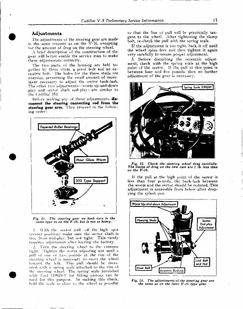
Cadillac V-8 Preliminary Service Information 13
Adjustments The adjustments of the steering gear are made
in the same manner as on the V-16, excepting for the amount of drag on the steering wheel.
A brief description of the construction of the gear will better enable the service man to make these adjustments correctly.
The two parts of the housing are held together by three studs, a pivot bolt and an eccentric bolt. The boles for the three studs are oversize, permitting the small amount of movement necessary to adjust the sector back-lash. The other two adjustments—worm up-and-down plav and sector shaft end-play--are similar to the' Cadillac 353.
Before making any of these adjustments, disconnect the steering connecting rod from the steering gear arm. Then proceed in the following order:
I Tapered Roller Bearings
i " J | J 355 Type Support |
Fig. 21. The steering gear on both cars is the same type as on the V-16, but is not as heavy.
1. With the sector well off the high spot (center position) make sure the sector shaft is free from end-play, but not tight. This rarely requires adjustment after leaving the factory.
2. Turn the steering wheel to the extreme right. Tighten the worm adjusting nut until a pull of one or two pounds at the rim of the steering wheel is necessary to move the wheel toward the left. This pull should be measured with a spring scale attached to the rim ot the steering wheel. The spring scale furnished with Tool IIWJy-T for fitting pistons can be used for this purpose. In making this check, hold the scale as close to the wheel as possible
so that the line of pull will be practically tangent to the wheel. After tightening the clamp bolt, re-check the pull with the spring scale.
If the adjustment is too tight, back it off until the wheel spins free and then tighten it again very carefully to secure proper adjustment.
3. Before disturbing the eccentric adjustment, check with the spring scale at the high point of the sector. If the pull at this point is between four and five pounds, then no further adjustment of the gear is necessary.
Fig. 22. Check the steering wheel drag carefully. The limits of drag on the new cars are 1 lb. less than on the V-16.
If the pull at the high point of the sector is less than four pounds, the back-lash between the worm and the sector should be reduced. This adjustment is accessible from below after dropping the splash pan.
I ^^^fS^mmmmmmmmm^^ammm^mmmmmmmmmmmmmm^mm
Worm Up-and-down Adjustment}
I Housing Studs Sector Endplay
Adjustment
(pivof Bolt r " | ' I *——"~"~J [Eccentric Bushing I
Lock Bolt and Nut
Fig. 23. The adjustments of the steering gear are the same as on the later V-16 type gear.
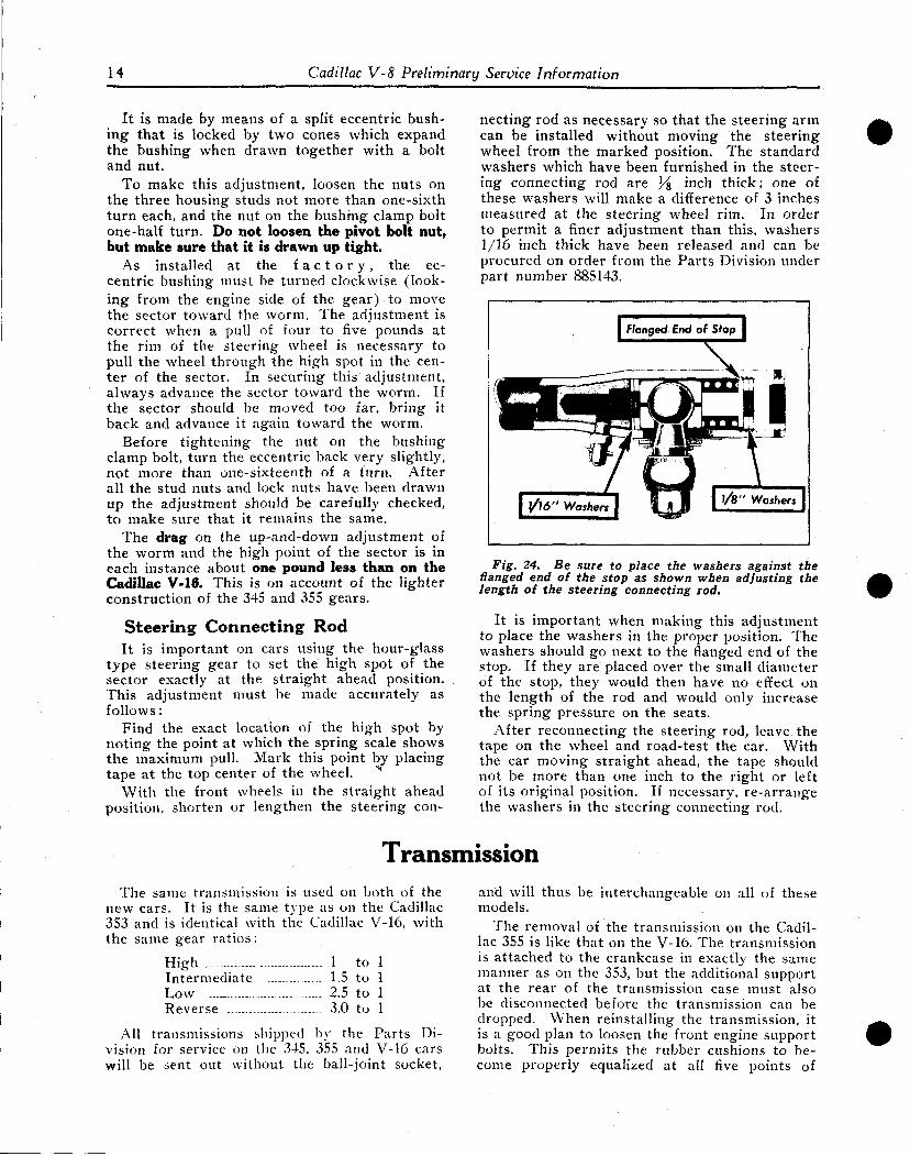
14 Cadillac V-8 Preliminary Service Information
It is made by means of a split eccentric bushing that is locked by two cones which expand the bushing when drawn together with a bolt and nut.
To make this adjustment, loosen the nuts on the three housing studs not more than one-sixth turn each, and the nut on the bushing clamp bolt one-half turn. Do not loosen the pivot bolt nut, but make sure that it is drawn up tight.
As installed at the f a c t o r y , the eccentric bushing must be turned clockwise (looking from the engine side of the gear) to move the sector toward the worm. The adjustment is correct when a pull of four to five pounds at the rim of the steering wheel is necessary to pull the wheel through the high spot in the center of the sector. In securing this adjustment, always advance the sector toward the worm. If the sector should be moved too far, bring it back and advance it again toward the worm.
Before tightening the nut on the bushing clamp bolt, turn the eccentric back very slightly, not more than one-sixteenth of a turn. After all the stud nuts and lock nuts have been drawn up the adjustment should be carefully checked, to make sure that it remains the same.
The drag on the up-and-down adjustment of the worm and the high point of the sector is in each instance about one pound less than on the Cadillac V-16. This is on account of the lighter construction of the 345 and 355 gears.
Steering Connecting Rod It is important on cars using the hour-glass
type steering gear to set the high spot of the sector exactly at the straight ahead position. This adjustment must be made accurately as follows:
Find the exact location of the high spot by noting the point at which the spring scale shows the maximum pull. Mark this point by placing tape at the top center of the wheel. ""
With the front wheels in the straight ahead position, shorten or lengthen the steering con-
The same transmission is used on both of the new cars. It is the same type as on the Cadillac 353 and is identical with the Cadillac V-16, with the same gear ratios:
High ..... 1 to 1 Intermediate 1.5 to 1 Low 2.5 to 1 Reverse ..— 3.0 to 1
All transmissions shipped by the Parts Division for service on the 345, 355 and V-16 cars will be sent out without the ball-joint socket,
necting rod as necessary so that the steering arm can be installed without moving the steering wheel from the marked position. The standard washers which have been furnished in the steering connecting rod are ]/z inch thick; one of these washers will make a difference of 3 inches measured at the steering wheel rim. In order to permit a finer adjustment than this, washers 1/16 inch thick have been released and can be procured on order from the Parts Division under part number 885143.
Fig. 24. Be sure to place the washers against the Hanged end of the stop as shown when adjusting the length of the steering connecting rod.
It is important when making this adjustment to place the washers in the proper position. The washers should go next to the flanged end of the stop. If they are placed over the small diameter of the stop, they would then have no effect on the length of the rod and would only increase the spring pressure on the seats.
After reconnecting the steering rod, leave the tape on the wheel and road-test the car. With the car moving straight ahead, the tape should not be more than one inch to the right or left of its original position. If necessary, re-arrange the washers in the steering connecting rod.
and will thus be interchangeable on all of these models.
The removal of the transmission on the Cadillac 355 is like that on the V-16. The transmission is attached to the crankcase in exactly the same manner as on the 353, but the additional support at the rear of the transmission case must also be disconnected before the transmission can be dropped. When reinstalling the transmission, it is a good plan to loosen the front engine support bolts. This permits the rubber cushions to become properly equalized at all five points of
Transmission
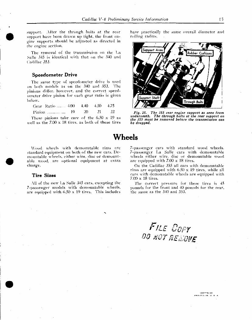
Cadillac V-8 I'reliminary Service Information 15
support. After the through bolts at the rear support have been drawn up tight, the front engine supports should be adjusted as directed in the engine section
'Hie nit: engine sct-ut/ii.
The removal of the transmission on the La Salle 345 is identical with that on the 340 and Cadillac 353.
Speedometer Drive The same type of speedometer drive is used
on both models as on the 340 and 353. The pinions differ, however, and the correct speedometer drive pinion for each gear ratio is given below.
Gear Ratio ....4.00 4.40 4.50 4.75
Pinion - 19 20 21 22
These pinions take care of the 6.50 x 19 as well as the 7.00 x 18 tires, as both of these tires
have practical!} the same overall diameter and rolling radius.
Fig. 25. The 355 rear engine support as seen from underneath. The through bolts at the rear support on the 355 must be removed before the transmission can be dropped.
Wheels Wood wheels with demountable rims are
standard equipment on both of the new cars. Demountable wheels, either wire, disc or demountable wood, are optional equipment at extra charge.
Tire Sizes
All of the new La Salle 345 cars, excepting the 7-passenger models with demountable wheels, are equipped with 6.50 x 19 tires. This includes
7-passenger cars with standard wood wheels. 7-passenger La Salle cars with demountable wheels either wire, disc or demountable wood are equipped with 7.00 x 18 tires.
On the. Cadillac 355 all cars with demountable rims are equipped with 6.50 x 19 tires, Avhile all cars with demountable wheels are equipped with 7.00 x 18 tires.
The correct pressure, for these tires is 45 pounds for the front and 40 pounds for the rear, the same as the 340 and 353.
/ » / / r* COPY
DOmTBE&QyE
100 9-30 P H I N T T O I N U S A
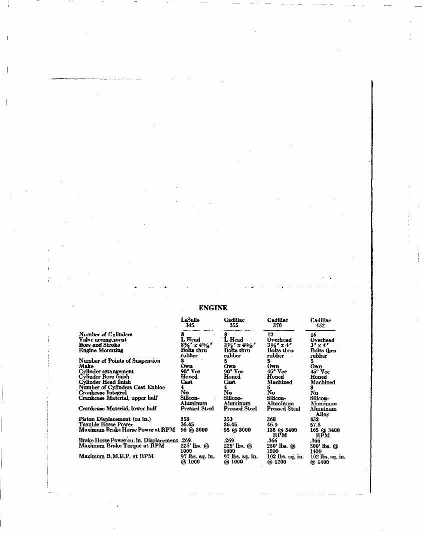
ENGINE LaSalle
345
Number of Cylinders Valve arrangement Bore and Stroke Engine Mounting
Number of Points of Suspension Make Cylinder arrangement Cylinder Bore finish Cylinder Head finish Number of Cylinders Cast Enbloc Crankcase Integral Crankcase Material, upper half
Crankcase Material, lower half
8 LHead 3%' x <vw Bolts thru rubber 3 Own 90° Vee Honed Cast 4 No Silicon-Aluminum Pressed Steel
Piston Displacement (cu in.) 353 Taxable Horse Power 36.45 Maximum Brake Horse Power at RPM 95 @ 3000
Brake Horse Power cu. in. Displacement .269. Maximum Brake Torque at RPM 225' lbs. @
1000 Maximum B.M.E.P. at RPM 97 lbs. sq. in.
@1000
Cadillac 355
1 LHead 3 % " x 4 W Bolt* thru rubber 5 Own 90°Vee Honed Cast 4 No Silicon-Aluminum Pressed Steel
353 36.45 95 @ 3000
.269 225' lbs. @ 1000 97 lbs. sq. in. ©1000
Cadillac 370
_ _
Overhead 3 ^ " x 4 * Bolts thru rubber 5 Own 45° Vee Honed Machined 6 No Silicon-Aluminum Pressed Steel
368 46.9 135 @ 3400
RPM .366 250' lbs. © 1200 102 lbs. sq. in. ©1200
Cadillac 452
~16 Overhead 3"x4" Bolts thru rubber 5 Own 45° Vee Honed Machined 8 No Silicon-Aluminum Aluminum
Alloy 452 57.5 165 © 3400
RPM .366 300' lbs. @ 1400 102 lbs. sq. in. @ 1400
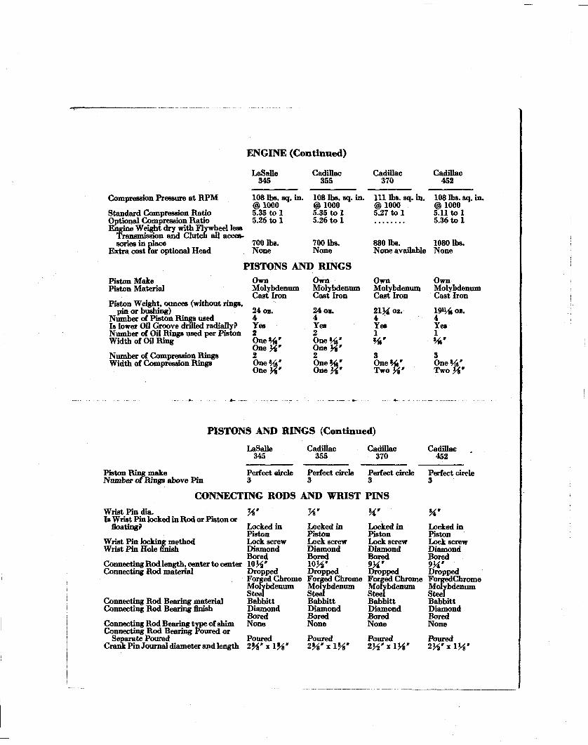
E N G I N E ( C o n t i n u e d )
LaSalle 345
Compression Pressure at RPM
Standard Compression Ratio Optional Compression Ratio Engine Weight dry with Flywheel less
Transmission and Clutch all accessories in place
Extra cost for optional Head
108 lbs. sq. in. @1000 5.35 to 1 5.26 to 1
700 lbs. None
Cadillac 355
108 lbs; sq. in. @1000 5.35 to 1 5.26 to 1
700 lbs. None
PISTONS AND RINGS Piston Make Piston Material
Piston Weight, ounces (without rings, pin or bushing)
Number of Piston Rings used Is lower OO Groove drilled radially? Number of Oil Rings used per Piston Width of Oil Ring
Number of Compression Rings Width of Compression Rings
Own Molybdenum Cast Iron
24 oz. 4 Yes 2 One *A' O n e J ? ' 2 One «4 One
Own Molybdenum Cast Iron
24 oz. 4 Yes 2 One»/f,» One J* ' 2 Cta»*A' O n e J ? '
Cadillac 370
111 lbs. sq. in. @1000 5.27 to 1
880 lbs. None available
Own Molybdenum Cast Iron
21½ oz. 4 ' Yes 1
One*/ Two %"•
Cadillac 452
108 lbs. sq. in. ©1000 5.11 to 1 5.36 to 1
1080 lbs. None
Own Molybdenum Cast Iron
1911/6 oz. 4 Yes 1
w 3 One *A' TwoJ*»
P I S T O N S A N D R I N G S ( C o n t i n u e d )
LaSalle 345
Piston Ring make Number of Rings above Pin
Perfect oircle 3
Cadillac 355
Perfect circle 3
Cadillac 370
Perfect circle 3
CONNECTING RODS AND WRIST PINS
Wrist Pin dia. Is Wrist Pin locked in Rod or Piston or
floating?
Wrist Pin locking method Wrist Pin Hole finish
Connecting Rod length, center to center Connecting Rod material
Connecting Rod Bearing material Connecting Rod Bearing finish
Connecting Rod Bearing type of shim Connecting Rod Bearing Poured or
Separate Poured Crank Pin Journal diameter and length
%' W
Cadillac 452
Perfect circle 3
%" Locked in Piston Lock screw Diamond Bored 1 0 ^ ' Dropped Forged Chrome Molybdenum Steel Babbitt Diamond Bored None
Poured 2 ^ ' x l ^ '
Locked in Piston Lock screw Diamond Bored 10M" Dropped Forged Chrome Molybdenum Steel Babbitt Diamond Bored None
Poured 2%'%\%"
Locked in Piston Lock screw Diamond Bored 9H' Dropped Forged Chrome Molybdenum Steel Babbitt Diamond Bored None
Poured 2H"*lH'
Locked in Piston Lock screw Diamond Bored 9H' Dropped ForgedChrome Molybdenum Steel Babbitt Diamond Bored None
Poured 2H"*iys'
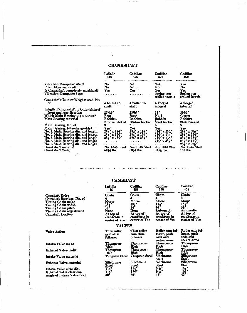
CRANKSHAFT
Vibration Dampener used? Front Flywheel used? Is Crankshaft completely machined? Vibration Dampener type
Crankshaft Counter Weights used, No. of
Length of Crankshaft to Outer Ends of front and rear Bearings
Which Main Bearing takes thrust? Main Bearing material
Main Bearing, No. of Main Bearing, Interchangeable? No. 1 Main Bearing dia. and length No. 2 Main Bearing dia. and length No. 3 Main Bearing dia. and length No. 4 Main Bearing dia. and length No. 5 Main Bearing dia. and length Crankshaft material Crankshaft Weight
LaSalle 345
No No Yes
4 bolted to shaft
2 3 % ' Rear Babbitt-Bronze backed 3 Yet 2%"x\%" 2*A'x\W 2H'x2H'
No. 1045 Steel 68¾ lbs.
Cadillac 353
No No Yes
4 bolted to shaft
23%» Rear Babbitt-Bronze backed 3 Yes 2%'xlH' 2H"xl$i' 2H"x2W
No. 1045 Steel 68H lbs-
Cadillac 370
Yes No Yes Spring controlled inertia
4 Fbrged integral
31» No.t Babbitt Steel backed 4 Yes 2H' x %' 2H'xlH' 2H'xiH' 2Wx&Ar No. 1045 Steel 83½ lbs.
Cadillac 452
Yes No Yes Spring controlled inertia
4 Forged integral
39¼ ' Center Babbitt Steel backed 5 Yes 25*' x 2%* 2Wx\%" 2Wx\W 2H"xl%' 25*» x 3 % ' No. 1045 Steel 130 lbs.
CAMSHAFT
Camshaft Drive Camshaft Bearings, No. of Timing Chain make Timing Chain width Timing Chain pitch Timing Chain adjustment Camshaft location
Valve Action
Intake Valve make
Exhaust Valve make
Intake Valve material
Exhaust Valve material
Intake Valve clear dia. Exhaust Valve clear dia. Angle of Intake Valve Seat
LaSalle 345
Chain 4 Morse \H' a
Cadillac 355
Chain 4 Morse
\w one
At top of crankcasein center of Vee
8 one At top of crankcasein center of Vee
VALVES Thru roller cam slide follower
Thru roller cam slide follower
Thompson- Thompson-Rich Rich Thompson- Thompson-Rich Rich Tungsten Steel Tungsten Steel
SiKchrome Steel
I H ' 30°
Cadillac 370
Chain 4 Morse
¥ Automatic At top of crankcasein center of Vee
Roller cam follower, push rods and rocker arms Thompson-Rich Thompson-Rich Silichrome Steel SiKchrome Steel 1%' 1%' 45°
Cadillac 452
Chain' 5 Morse IH'
W Automatic At top of crankcase in center of Vee
Roller cam follower, push rods and rocker arms Thompson-Rich Thompson-Rich Silichrome Steel Silichrome Steel 1%' » * ' 45°
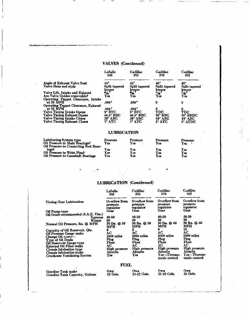
VALVES (Continued)
Angle of Exhuast Valve Seat Valve Stem end style
Valve Lift, Intake and Exhaust Are Valve Guides removable? Operating Tappet Clearance, Intake
at 35 MPH Operating Tappet Clearance, Exhaust
Valve Timing Intake Opens Valve Timing Exhaust Opens Valve Timing Intake Closes Valve Timing Exhaust Closes
LaSalle 345
45° Split tapered keeper € .006'
.004' 9°BTC 46.5° BBC 58° ABC 7°ATC
Cadillac 355
45° Split tapered keeper «%r
Yes
.006'
.004' 9°BTC 46.5° BBC 58° ABC 7°ATC
Cadillac 370
45° Split tapered keeper
Yes
0
0 TDC 39° BBC 44° ABC 5°ATC
Cadillac 452
45° Split tapered keeper "4t* Yes
0
0 TDC 39° BBDC 44° ABC 5° ATDC
LUBRICATION
Lubricating System type Pressure Pressure Oil Pressure to Main Bearings? Yes Yes Oil Pressure to Connecting Rod Bear
ings? Yes Yes Oil Pressure to Wrist Pins? Yes Yes Oil Pressure to Camshaft Bearings Yes Yes
Pressure Yes
Yes Yes Yes
Pressure Yes '
Yes Yes Yes
LUBRICATION (Continued)
Timing Gear Lubrication
Oil Pump type Oil Grade recommended (S.A.E. Vise.)
Summer Winter
Normal Oil Pressure, lbs. @ MPH
Capacity of Oil Reservoir, Qts. Oil Pressure Gauge make Change Oil every— Type of Oil Dram Oil Reservoir Gauge type External Oil Filter make Chassis lubrication type Chassis lubrication make Crankcase Ventilating System
Gasoline Tank make Gasoline Tank Capacity, Gallons
LaSalle 345
Overflow from pressure regulator Gear
40-50 20 30 lbs. @ 30 MPH 8 AC 2000 miles Plug Float AC High pressure Alemite Yes
Cadillac 355
Overflow from pressure regulator Gear
40-50 20 30 lbs. @ 30 MPH 8 AC 2000 miles Plug Float AC High pressure Alemite Yes
FUEL Own 23 Gals.
Own 21-22 Gals.
Cadillac 370
Overflow from pressure regulator Gear
40-50 20 30 lbs. @ 60 MPH 9 AC 2000 miles Hu* Float AC High pressure Alemite Yes—Thermostatic control
Own 21-22 Gals.
Cadillac 452
Overflow from pressure regulator Gear
40-50 20 30 lbs. @ 60 MPH 10 AC 2000 miles H"* Float AC High pressure Alemite Yes—Thermostatic control
Own 25 Gals.
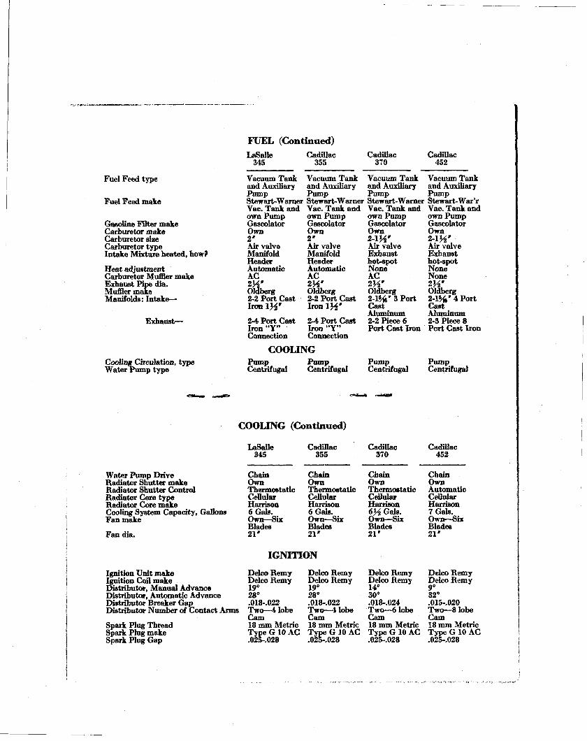
FUEL (Continued)
Fuel Feed type
Fuel Feed make
Gasoline Filter make Carburetor make Carburetor size Carburetor type Intake Mixture heated, how?
Heat adjustment Carburetor Muffler make Exhaust Pipe dia. Muffler make Manifolds: Intake—
Exhaust—
Cooling Circulation, type Water Pump type
LaSalle 345
Vacuum Tank and Auxiliary Pump Stewart-Warner Vac. Tank and own Pump Gascolator Own 2 ' Air valve Manifold Header Automatic AC 2H' Oldberg 2-2 Port Cast Iron IH'
2-4 Port Cast Iron"Y" Connection
Cadillac 355
Vacuum Tank and Auxiliary Pump Stewart-Warner Vac. Tank and own Pump Gascolator Own 2 ' Air valve Manifold Header Automatic AC 2H' Oldberg 2-2 Port Cast I r o n l ^ * 2-4 Port Cast Iron "Y" Connection
Cadillac 370
Cadillac 452
COOLING
Vacuum Tank and Auxiliary Pump Stewart-Warner Vac. Tank and own Pump Gascolator Own 2-1H' Air valve Exhaust hot-spot None AC 2H' Oldberg 2-1%* 3 Port Cast Aluminum 2-2 Piece 6 Port Cast Iron
Vacuum Tank and Auxiliary Pump Stewart-War'r Vac. Tank and own Pump Gascolator Own
Air valve Exhaust hot-spot None None 2 ^ ' Oldberg 2-1%' 4 Port Cast Aluminum 2-3 Piece 8 Port Cast Iron
Pump Centrifugal
Pump Centrifugal
Pump Centrifugal
Pump Centrifugal
COOLING (Continued)
Water Pump Drive Radiator Shutter make Radiator Shutter Control Radiator Core type Radiator Core make Cooling System Capacity, Gallons Fan make
Fan dia.
Ignition Unit make Ignition Coil make Distributor, Manual Advance Distributor, Automatic Advance Distributor Breaker Gap Distributor Number of Contact Arms
Spark Plug Thread Spark Plug make Spark Plug Gap
LaSalle 345
Chain Own Thermostatic Cellular Harrison 6 Gals. Own—Six Blades 21'
Cadillac 355
Chain Own Thermostatic Cellular Harrison 6 Gals. Own—Six Blades 21'
IGNITION
Delco Remy Delco Remy 19° 28° .018-.022 Two—4 lobe Cam 18 mm Metric Type G 10 AC .025-.028
Delco Remy Delco Remy 19° 28° .018-.022 Two—4 lobe Cam 18 mm Metric Type G 10 AC .025-.028
Cadillac 370
Chain Own Thermostatic Cellular Harrison 6½ Gals. Own—Six Blades 21'
Delco Remy Delco Remy 14° 30° .018-.024 Two—6 lobe Cam 18 mm Metric Type G 10 AC .025-.028
Cadillac 452
Chain Own Automatic Cellular Harrison 7 Gals. Own—Six Blades 21'
Delco Remy Delco Remy 9° 32° .015-.020 Two—8 lobe Cam 18 mm Metric Type G 10 AC .025-.028
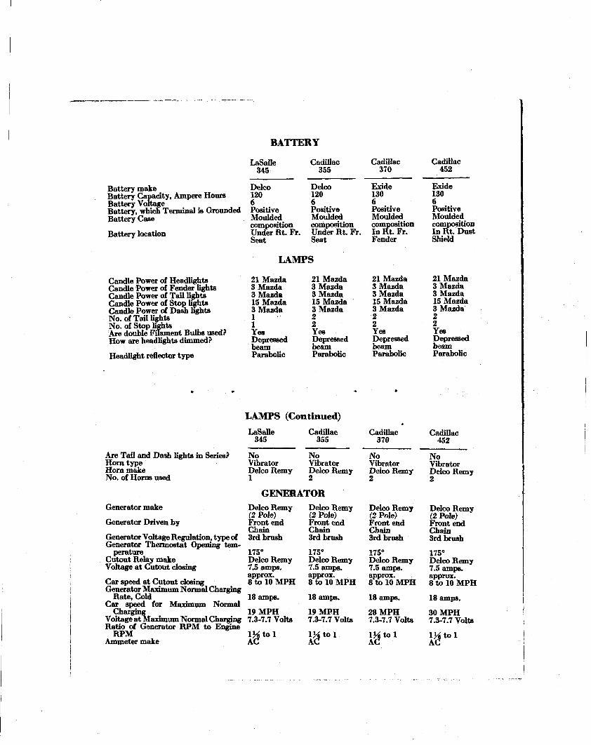
Battery make Battery Capacity, Ampere Hours Battery Voltage Battery, which Terminal is Grounded Battery Case Battery location
Candle Power of Headlights Candle Power of Fender lights Candle Power of Tail lights Candle Power of Stop lights Candle Power of Dash lights No. of Tail lights No. of Stop lights Are double Filament Bulbs used? How are headlights dimmed?
Headlight reflector type
BATTERY
LaSalle 345
Delco 120 6 Positive Moulded composition Under Rt. Fr. Seat
Cadillac 355
Delco 120 6 Positive Moulded composition Under Rt. Fr. Seat
LAMPS
21 Mazda 3 Mazda 3 Mazda IS Mazda 3 Mazda 1 1 Yes Depressed beam Parabolic
21 Mazda 3 Mazda 3 Mazda 15 Mazda 3 Mazda 2 2 Yes Depressed beam Parabolic
Cadillac 370
Exide 130 6 Positive Moulded composition In Rt. Fr. Fender
21 Mazda 3 Mazda 3 Mazda 15 Mazda 3 Mazda 2 2 Yes Depressed beam Parabolic
Cadillac 452
Exide 130 6 Positive Moulded composition In Rt. Dust Shield
21 Mazda 3 Mazda 3 Mazda 15 Mazda 3 Mazda 2 2 Yes Depressed beam Parabolic
L A M P S ( C o n t i n u e d )
Are Tail and Dash lights in Series? Horn type Horn make No. of Horns used
Generator make
Generator Driven by
Generator Voltage Regulation, type of Generator Thermostat Opening tem
perature Cutout Relay make Voltage at Cutout closing
Car speed at Cutout closing Generator Maximum Normal Charging
Rate, Cold Car speed for Maximum Normal
Charging Voltage at Maximum Normal Charging Ratio of Generator RPM to Engine
RPM Ammeter make
LaSalle 345
No Vibrator Delco Remy 1
Cadillac 355
No Vibrator Delco Remy 2
GENERATOR Delco Remy (2 Pole) Front end Chain 3rd brush
175° Delco Remy 7.5 amps. approx. 8 to 10 MPH 18 amps.
19 MPH 7.3-7.7 Volts
l ^ t o l AC
Delco Remy (2 Pole) Front end Chain 3rd brush
175° Delco Remy 7.5 amps. approx. 8 to 10 MPH 18 amps.
19 MPH 7.3-7.7 Volts
l ^ t o l AC
Cadillac 370
No Vibrator Delco Remy 2
Delco Remy (2 Pole) Front end Chain 3rd brush
175° Delco Remy 7.5 amps. approx. 8 to 10 MPH 18 amps.
28 MPH 7.3-7.7 Volts
l ^ t o l AC
Cadillac 452
No Vibrator Delco Remy 2
Delco Remy (2 Pole) Front end Chain 3rd brush
175° Delco Remy 7.5 amps. approx. 8 to 10 MPH 18 amps.
30 MPH 7.3-7.7 Volts
A C ^ 1
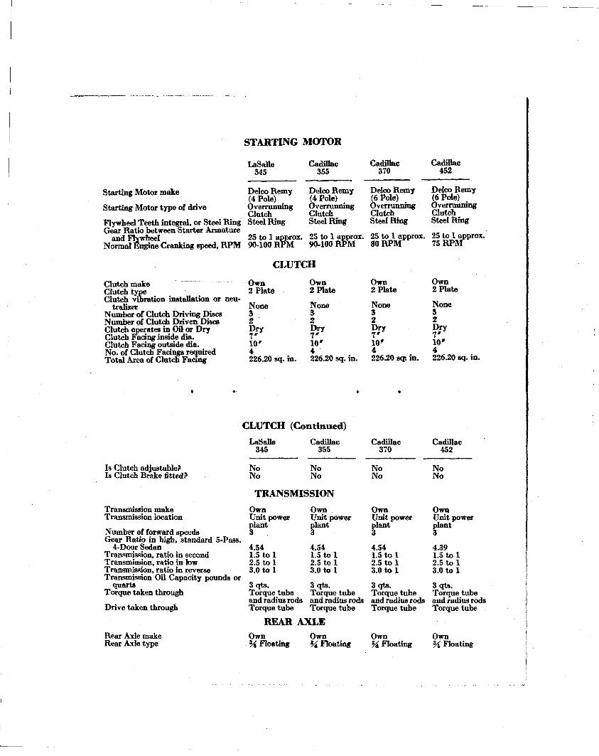
S T A R T I N G M O T O R
LaSalle 345
Starting Motor make
Starting Motor type of drive
Flywheel Teeth integral, or Steel Ring Gear Ratio between Starter Armature
and Flywheel Normal Engine Cranking speed, RPM
Delco Remy (4 Pole) Overrunning Clutch Steel Ring
25 to 1 approx. 90-100 RPM
Cadillac 355
Delco Remy (4 Pole) Overrunning Clutch Steel Ring
25 to 1 approx. 90-100 RPM
C L U T C H
Clutch make Own Own Clutch type 2 Plata 2 Plate Clutch vibration installation or neu-
tralizer None None Number of Clutch Driving Discs 3 3 Number of Clutch Driven Discs 2 2 Clutch operates in Oil or Dry Dry Dry Clutch Facing inside dia. 7 * " Clutch Facing outside dia. 10 ' 10* No. of Clutch Facings required 4 4 Total Area of Clutch Facing 226.20 sq. in. 226.20 sq. in.
Cadillac 370
Delco Remy (6 Pole) Overrunning Clutch Steel Ring
25 to 1 approx. 80 RPM
Own 2 Plate
None 3 2 Dry 7 ' 10» 4
Cadillac 452
Delco Remy (6 Pole) Overrunning Clutch Steel Ring
25 to 1 approx. 75 R P M
Own 2 Plate
None 3 2 Dry 7 ' 10» 4
226.20 sqs in. 226.20 sq. in.
C L U T C H ( C o n t i n u e d )
Is Clutch adjustable? Is Clutch Brake fitted?
Transmission make Transmission location
Number of forward speeds Gear Ratio in high, standard 5-Pass.
4-Door Sedan Transmission, ratio in second Transmission, ratio in low Transmission, ratio in reverse Transmission Oil Capacity pounds or
quarts Torque taken through
Drive taken through
Rear Axle make Rear Axle type
LaSalle 345
No No
Cadillac 355
No No
TRANSMISSION
Own Unit power plant 3
4.54 1.5 to 1 2.5 to 1 3.0 to 1
3qts . Torque tube and radius rods Torque tube
Own Unit power plant 3
4.54 1.5 to 1 2.5 to 1 3.0 to 1
3qts . Torque tube and radius rods Torque tube
REAR AXLE Own % Floating
Own % Floating
Cadillac 370
No No
Own Unit power plant 3
4.54 1.5 to 1 2.5 to 1 3.0 to 1
3 qts. Torque tube and radius rods Torque tube
Own % Floating
Cadillac 452
No No
Own Unit power plant 3
4.39 1.5 to 1 2.5 to 1 3.0 to 1
3 qts. Torque tube and radius rods Torque tube
Own M Floating
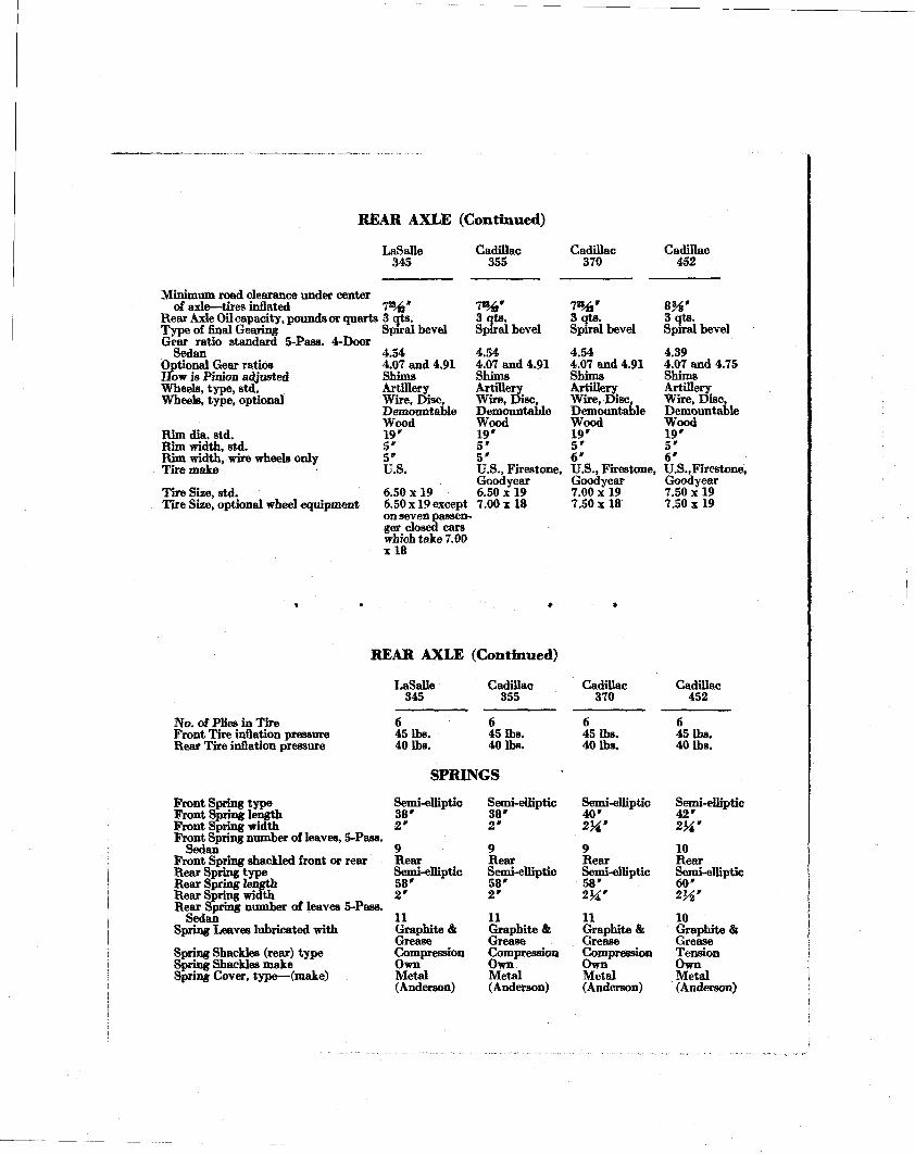
REAR AXLE (Continued)
LaSsJIe 345
Minimum road clearance under center of axle—tires inflated
Rear Axle Oil capacity, pounds or quarts Type of final Gearing Gear ratio standard 5-Pass. 4-Door
Sedan Optional Gear ratios How is Pinion adjusted Wheels, type, std. Wheels, type, optional
Rim dia. std. Rim width, std. Rim width, wire wheels only Tire make
Tire Size, std. Tire Size, optional wheel equipment
7 % ' 3 qts. Spiral bevel
4.54 4.07 and 4.91 Shims Artillery Wire, Disc, Demountable Wood 19 ' 5 ' 5 ' U.S.
6.50 x 19 6.50 x 19 except on seven passenger closed cars which take 7.00 x ! 8
Cadillac 355
7%» 3 qts. Spiral bevel
4.54 4.07 and 4.91 Shims Artillery Wire, Disc, Demountable Wood 19 ' 5 ' 5 ' U.S., Firestone, Goodyear 6.50 x 19 7.00 x 18
Cadillac 370
7 % ' 3 qts. Spiral bevel
Cadillac 452
m' 3 qts. Spiral bevel
4.54 4l07 and 4.91 Shims Artillery^ Wire, Disc, Demountable Wood 19 ' 5 ' 6 ' U.S., Firestone, Goodyear 7.00 x 19 7.50 x 18
4.39 4.07 and 4.75 Shims Artillery Wire, Disc, Demountable Wood 19 ' 5 ' 6 ' U.S.,Fire8tone, Goodyear 7.50 x 19 7.50 x 19
REAR AXLE (Continued)
No. of Plies in Tire Front Tire inflation pressure Rear Tire inflation pressure
Front Spring type Front Spring length Front Spring width Front Spring number of leaves, 5-Pass.
Sedan Front Spring shackled front or rear Rear Spring type Rear Spring length Rear Spring width Rear Spring number of leaves 5-Pass.
Sedan Spring Leaves lubricated with
Spring Shackles (rear) type Spring Shackles make Spring Cover, type—(make)
LaSalle 345
6 45 lbs. 40 lbs.
Cadillac 355
6 45 lbs. 40 lbs.
SPRINGS
Semi-elliptic 38 ' 2 '
9 Rear Semi-elliptic 58 ' 2 '
11 Graphite & Grease Compression Own Metal (Anderson)
Semi-elliptic 3 8 ' 2 '
9 Rear Semi-elliptic 5 8 ' 2 '
11 Graphite & Grease Compression Own Metal (Anderson)
Cadillac 370
6 45 lbs. 40 lbs.
Semi-elliptic 40 ' 2H' 9 Rear Semi-elliptic 58 ' 2Hr
11 Graphite & Grease Compression Own Metal (Anderson)
Cadillac 452
6 45 lbs. 40 lbs.
Semi-elliptic 42 ' 2H' 10 Rear Semi-elliptic 60 '
m' 10 Graphite & Grease Tension Own Metal (Anderson)
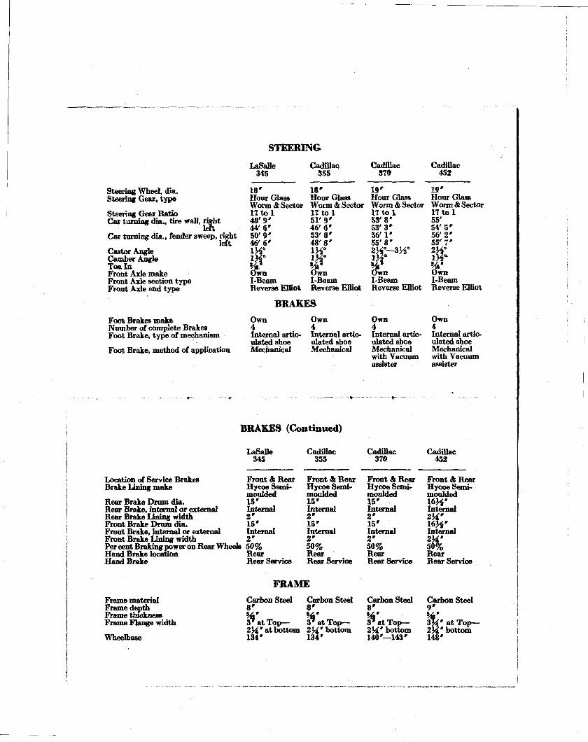
Steering Wheel, dia. Steering Gear, type
Steering Gear Ratio Car turning dia., tire wall, right
left Car turning dia., fender sweep, right
left Castor Angle Camber Angle Toe In Front Axle make Front Axle section type Front Axle end type
Foot Brakes make Number of complete Brakes Foot Brake, type of mechanism
Foot Brake, method of application
STEERING LaSaUe
345
18' Hour Glass Worm & Sector 1 7 t o l 48 '9 ' 44'6* 50' 9" 46'6 ' 1¼0
1½ 0
Own I-Beam Reverse Effiot
Cadillac 355
18' Hour Glass Worm & Sector 1 7 t o l 51 '9 ' 46 '6 ' 53 '8 ' 4 8 ' 8 ' 1¾° 1½°
Own I-Beam Reverse Elliot
BRAKES Own 4 Internal artic-ulatedshoe Mechanical
Own 4 Internal articulated shoe Mechanical
Cadillac 370
15 ' Hour Glass Worm & Sector l 7 t o l 53' 8 ' 53'3* 56'1* 55'8» 2 ^ - - 3 ½ 0
Own I-Beam Reverse Elliot
Own 4 Internal articulated shoe Mechanical with Vacuum assister
Cadillac 45¾
19' Hour Glass Worm & Sector 1 7 t o l 55' 54'5* 56 '2 ' 55 '7 ' 2½° Di° W Own I-Beam Reverse Elliot
Own 4 Internal articulated shoe Mechanical with Vacuum assister
BRAKES (Continued)
Location of Service Brakes Brake Lining make
Rear Brake Drum dia. Rear Brake, internal or external Rear Brake Lining width Front Brake Drum dia. Front Brake, internal or external Front Brake Lining width Per cent Braking power on Rear Wheeb Hand Brake location Hand Brake
Frame material Frame depth Frame thickness Frame Flange width
Wheelbase
LaSaUe 345
Front & Rear Hycoe Semi-moulded 15' Internal 2 ' 15* Internal 2 ' 50% Rear Rear Service
Cadillac 355
Front & Rear Hycoe Semi-moulded 15' Internal 2 ' 15' Internal 2 ' 50% Rear Rear Service
FRAME Carbon Steel 8 '
3* at Top— 2%'at bottom 134'
Carbon Steel 8 ' »4' 3* at Top— 2¾ 'bottom 134'
Cadillac 370
Front & Rear Hycoe Semi-moulded 15' Internal 2 ' 15' Internal 2 ' 50% Rear Rear Service
Carbon Steel 8 ' s 4 ' 3* at Top— 2½'bottom 140'—143*
Cadillac 452
Front & Rear Hycoe Semi-moulded 1 6 ^ ' Internal
! & • Internal 2HL* 50% Rear Rear Service
Carbon Steel 9 '
3M' at Top— 2½'bottom 148'
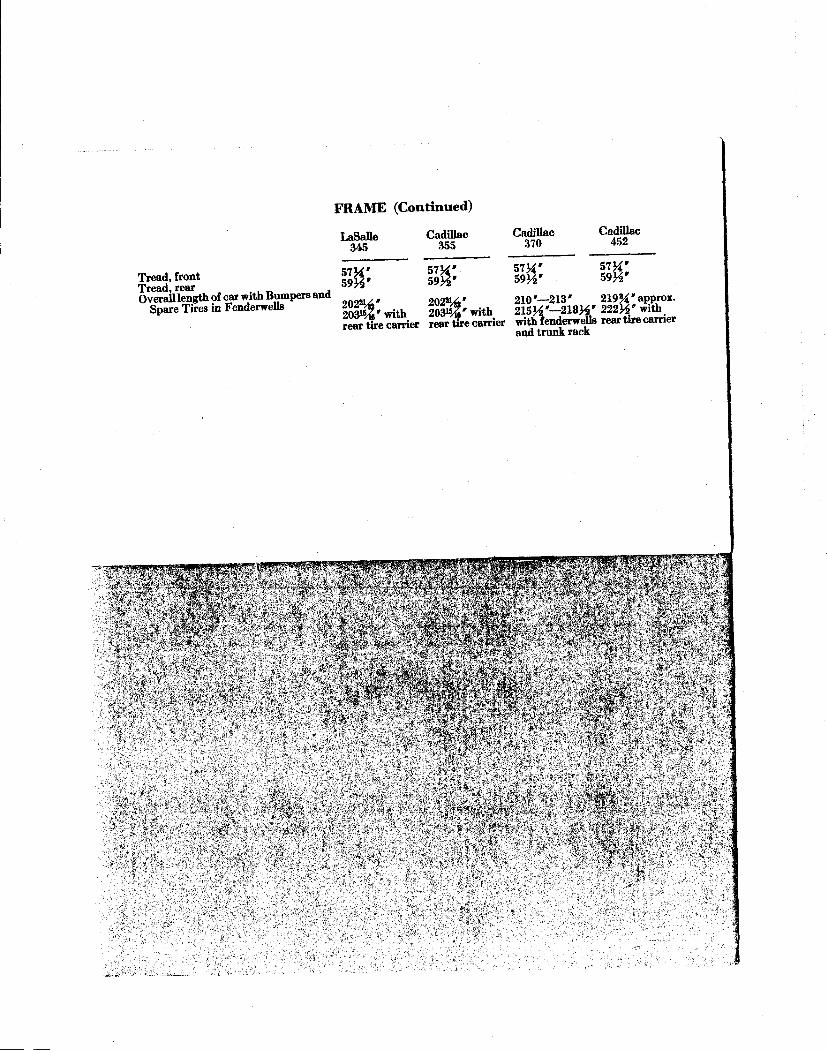
F R A M E ( C o n t i n u e d )
LaSalle 345
Tread, front Tread, rear Overall length of car with Bumpers and
Spare Tires in Fenderwells
Cadillac 355
57¾ ' 59½ '
202%' 203%' with rear tire carrier
57>£' 59½'
202%' 203%' with rear tire carrier
Cadillac 370
57¾ ' 59H»
Cadillac 452
57&' 59H'
210 '—213 ' 219¾ ' appro*. 215H"~218H' 2 2 2 ^ with with fenderwells rear tire carrier and trunk rack
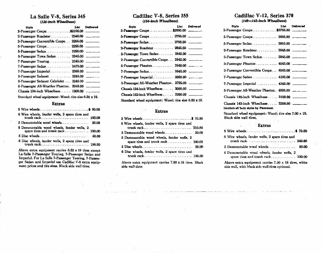
La Salle V-8, Series 345 (.134-inch Wheelbase)
Style List Delivered 2-Passenger Coupe $2195.00 2-Passenger Roadster 2245.00 2-Passenger Convertible Coupe... 2295.00 5-Passenger Coupe 2295.00 5-Passenger Sedan 2295.00 5-Passenger Town Sedan 2345.00 7-Passenger Touring 2345.00 7-Passenger Sedan 2475.00 7-Passenger Imperial 2595.00 _ 5-Passenger Sedanet 3245.00 5-Passenger Sedanet Cabriolet... 3245.00 5-Passenger All-Weather Phaeton. 3245.00 Chassis 134-inch Wheelbase 1900.00 Standard wheel equipment: Wood; tire size 6.50 x 19.
Extras 5 Wire wheels $ 60.00 6 Wire wheels, fender wells, 2 spare tires and
trunk rack 190.00 5 Demountable wood wheels 50.00 6 Demountable wood wheels, fender wells, 2
spare tires and trunk rack 190.00 5 Disc wheels 50.00 6 Disc wheels, fender wells, 2 spare tires and
trunk rack 190.00 Above extra equipment carries 6.50 x 19 tires except La Salle 7-Passenger Touring, 7-Passenger Sedan and Imperial. For La Salle 7-Passenger Touring, 7-Passenger Sedan and Imperial use Cadillac V-8 extra equipment prices and tire sizes. Black side wall tires.
Cadillac V-8, Series 355 (134-inch Wheelbase)
Style List Delivered 2-Passenger Coupe $2695.00
5-Passenger Coupe 2795.00
5-Passenger Sedan 2795.00
2-Passenger Roadster 2845.00
5-Passenger Town Sedan 2845.00
2-Passenger Convertible Coupe... 2945.00
5-Passenger Phaeton. . . , , . . 2945.00
7-Passenger Sedan 2945.00
7-Passenger Imperial. 3095.00
5-Passenger All-Weather Phaeton. 3795.00
Chassis 134-inch Wheelbase .. 2000.00
Chassis 152-inch Wheelbase. 2200.00
Standard wheel equipment: Wood; tire size 6.50 x 19.
Extras 5 Wire wheels $ 70.00 6 Wire wheels, fender wells, 2 spare tires and
trunk rack 210.00 5 Demountable wood wheels 50.00 6 Demountable wood wheels, fender wells, 2
spare tires and trunk rack 190.00 5 Disc wheels 50.00 6 Disc wheels, fender wells, 2 spare tires and
trunk rack 190.00 Above extra equipment carries 7.00 x 18 tires. Black side wall tires.
Cadillac V-12, Series 370 (140—143-inch Wheelbase)
Style List Delivered 2-Passenger Coupe $3795.00
5-Passenger Coupe 3895.00
5-Passenger Sedan 3895.00
2-Passenger Roadster 3945.00
5-Passenger Town Sedan 3945.00
5-Passenger Phaeton 4045.00
2-Passenger Convertible Coupe... 4045.00
7-Passenger Sedan 4195.00
7-Passenger Imperial 4345.00
5-Passenger All-Weather Phaeton. 4895.00
Chassis 140-inch Wheelbase 3100.00
Chassis 143-inch Wheelbase . 3200.00 Interiors all body styles by Fleetwood.
Standard wheel equipment: Wood; tire size 7.00 x 19. Black side wall tires.
Extras 5 Wire wheels $ 70.00
6 Wire wheels, fender wells, 2 spare tires and trunk rack 240.00
5 Demountable wood wheels 50.00
6 Demountable wood wheels, fender wells, 2 spare tires and trunk rack 230.00
Above extra equipment carries 7.50 x 18 tires, white side wall, with black side wall tires optional.
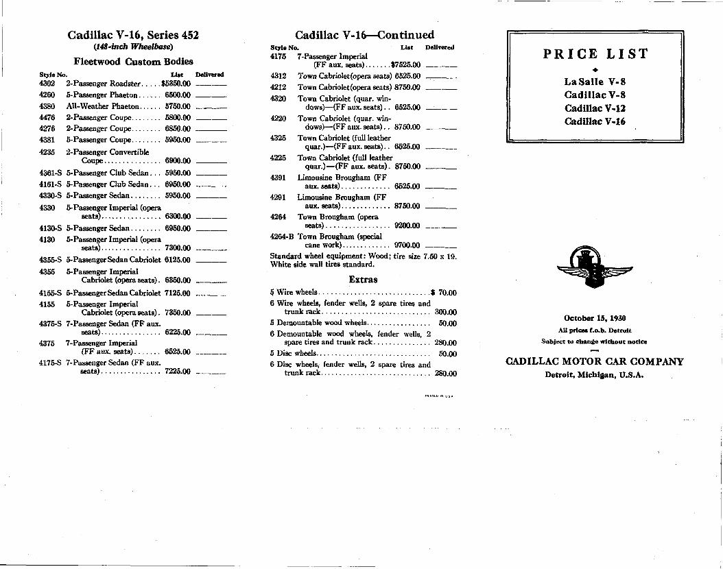
Cadillac V-16, Series 452 (.148-inch Wheelbase)
Fleetwood Custom Bodies Style No. List Delivered 4302 2-Passenger Roadster $5350.00 4260 5-Passenger Phaeton 6500.00 4380 All-Weather Phaeton 5750.00 4476 2-Passenger Coupe 5800.00 4276 2-Passenger Coupe 6850.00 4381 5-Passenger Coupe 5950.00 4235 2-Passenger Convertible
Coupe 6900.00 4361-S 5-Passenger Club Sedan. . . 5950.00 4161-S 5-Passenger Club Sedan... 6950.00 4330-S 5-Passenger Sedan 5950.00 4330 5-Passenger Imperial (opera
seats) 6300.00 4130-S 5-Passenger Sedan 6950.00 4130 5-Passenger Imperial (opera
seats) 7300.00 4355-S 5-Passenger Sedan Cabriolet 6125.00 4355 5-Passenger Imperial
Cabriolet (opera seats). 6350.00 4155-S 5-Passenger Sedan Cabriolet 7125.00 4155 5-Passenger Imperial
Cabriolet (opera seats). 7350.00 4375-S 7-Passenger Sedan (FF aux.
seats) 6225.00 4375 7-Passenger Imperial
(FF aux. seats) 6525.00 4175-S 7-Passenger Sedan (FF aux.
7225.00
Cadillac V-16—Continued Style No. List Delivered 4175 7-Passenger Imperial
(FF aux. seats) $7525.00 4312 Town Cabriolet (opera seats) 6525.00 4212 Town Cabriolet (opera seats) 8750.00 4320 Town Cabriolet (quar. win
dows)—(FF aux. seats).. 6525.00 4220 Town Cabriolet (quar. win
dows)—(FF aux. seats).. 8750.00 4325 Town Cabriolet (full leather
quar.)—(FFaux.seats).. 6525.00 4225 Town Cabriolet (full leather
quar.)—(FF aux. seats). 8750.00 4391 Limousine Brougham (FF
aux. seats) 6525.00 4291 Limousine Brougham (FF
aux. seats) 8750.00 4264 Town Brougham (opera
seats) 9200.00 4264-B Town Brougham (special
cane work) 9700.00 Standard wheel equipment: Wood; tire size 7.50 x 19. White side wall tires standard.
Extras 5 Wire wheels $ 70.00 6 Wire wheels, fender wells, 2 spare tires and
trunk rack 300.00 5 Demountable wood wheels 50.00 6 Demountable wood wheels, fender wells, 2
spare tires and trunk rack 280.00 5 Disc wheels 50.00 6 Disc wheels, fender wells, 2 spare tires and
trunk rack 280.00
PRICE L I S T
La Salle V-8 Cadillac V-8 Cadillac V-12 Cadillac V-16
October 15,1930 All prices f.o.b. Detroit
Subject to change without notice
CADILLAC MOTOR CAR COMPANY Detroit, Michigan, U.S.A.
102 T H E BOOK O r F L E E T W O O D
All fenders and chassis black. In addition, Fleetwood bodies in a variety of
rich colors, lighter in shade, will be brought through periodically for stock. Bulletins will announce these.
Colors available on open types, All-Weather types, and Sedanette types will be announced periodically.
UPHOLSTERY
EIGHT rich exclusive Fleetwood Doeskin Suede broadcloths by Wiese in subdued
colorings harmonizing with any exterior color. *
Exclusive Fleetwood Wiese broadcloths: Weise 2969 - - - - - - - - - - Green Gray Weise 2970 - - - - - - - - - Maroon Taupe Weise 2971 - - - - - - - - - - - - Tan Weise 2972 - - - - - - - - - - Silver Gray Weise 2973 - - - - - - - - - - Blue Gray Weise 2994 - - . - . Tan Taupe Wiese 3288 - - - - - - - - - - Dark Gray Wiese 3363 - - - - - - - - - -DarkTaupe
Optional in all enclosed drive and transformable types.
Three special Venetian mohairs of short nap.
Exclusive Fleetwood Venetian mohairs: 108-T - - - - - - - - - - - - - Green 109-T - - - - - - - - - - - - - Gray 110-T - - - - - - - - - - - - - Taupe
Optional in all enclosed drive and transformable types.
T H E BOOK O r F L E E T W O O D 103
The first two blend well with complementary body colors, Taupe, because of its neutral shade, going well with any color.
Fifteen special exclusive Fleetwood Aero leathers by Radel. These are lightweight, soft, pliable, and luxurious, four being specified for stock with the balance optional without extra charge, with a reasonable added time allowance.
Special Radel Aero leathers: 5885 - - - - - - - - - - - -Silver Gray
4 5 1 - - - - - - - - - - - - Pearl Gray 2646 - - - - - - - - - - - - Blue Gray 5897 - - - - - - - - - - - - Green Blue
68 - - - - - - - - - - Blue (Standard) 6016 - - - - - - - - - - - - Dark Blue 9205 - - - - - - - - - - - Deep Maroon 5875 - - - - - - - - - - - Rich Maroon 4339 - - - - - - - - - - Green (Standard)
/
Vanity cases are designed exclusively for Fleetwood bodies and contain 8-day clock, mirror, leather cigarette
case, and two ash receivers
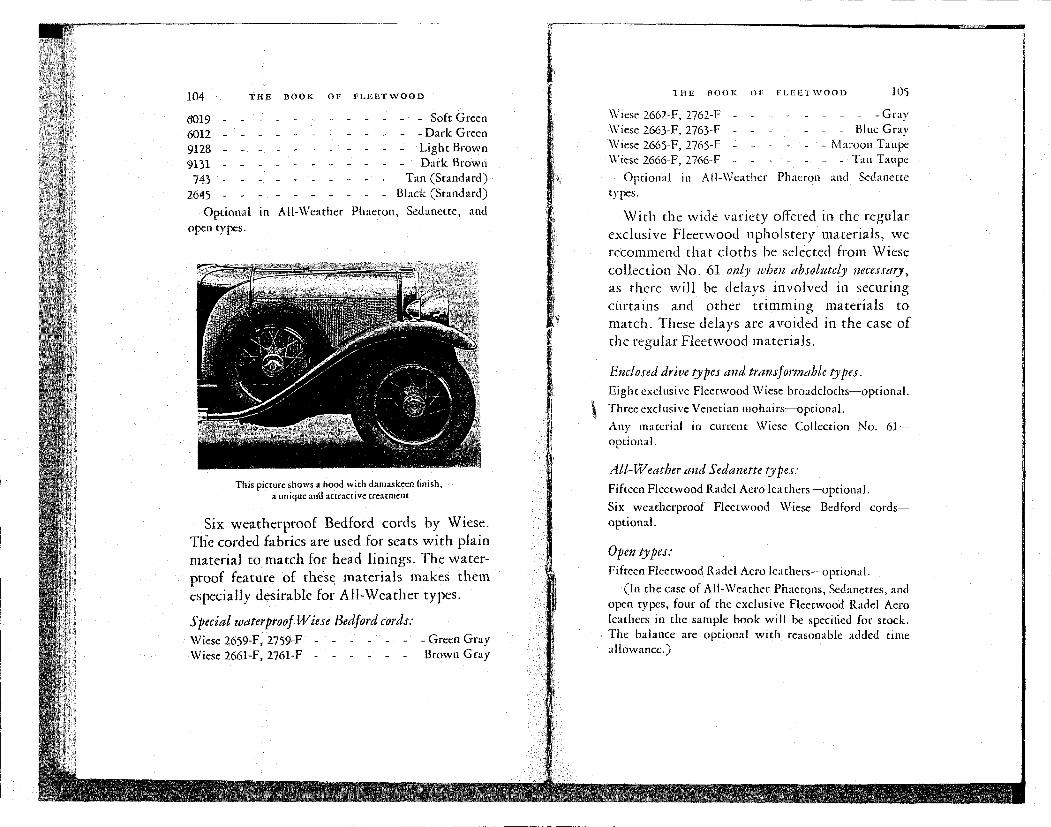
104 THE BOOK OF FLEETWOOD
0019 - - - - - - - - - - - - Soft Green 6012 - - - - - - - - - - - - Dark Green 9128 - - - - - - - - - - - Light Brown 9131 - . - - . - - - . - - Dark Brown
743 - . - . - - . - . - Tan (Standard) 2645 - . - - - - - - - - Black (Standard)
Optional in All-Weather Phaeton, Sedanette, and open types.
This picture shows a hood with damaskeen finish, a unique and attractive treatment
Six weatherproof Bedford cords by Wiese.
The corded fabrics are used for seats w i t h plain
material to match for head linings. The water
proof feature of these materials makes them
especially desirable for All-Weather types.
Special ivaterproof Wiese Bedford cords:
Wiese 2659-F, 2759-F - - - - - - - Green Gray Wiese 2661-F, 2761-F - - - - - - Brown Gray
THE BOOK Of FLEETWOOD 105
Wiese 2662-F, 2762-F - - - - - - - - -Gray Wiese 2663-F, 2763-F - - - - - - - Blue Gray \V1Cse 2665-F, 2765-F - - - - - - Maroon Taupe Wiese 2666-F, 2766-F - - - - - - - Tan Taupe
Optional in All-Weather Phaeton and Sedanette types.
Wi th the wide variety offered in the regular
exclusive Fleetwood upholstery materials, we
recommend that cloths be selected from Wiese
collection No . 61 only when absolutely necessary,
as there will be delays involved in securing
curtains and other t r imming materials to
match. These delays are avoided in the case of
the regular Fleetwood materials.
Enclosed drive types and transformable types.
Eight exclusive Fleetwood Wiese broadcloths—optional.
Three exclusive Venetian mohairs—optional.
Any material in current Wiese Collection No. 61— optional.
All-Weather and Sedanette types:
Fifteen Fleetwood Radel Aero leathers—optional.
Six weatherproof Fleetwood Wiese Bedford cords— optional.
Open types:
Fifteen Fleetwood Radel Aero leathers—optional.
(In the case of All-Weather Phaetons, Sedanettes, and open types, four of the exclusive Fleetwood Radel Aero leathers in the sample book will be specified for stock. The balance are optional with reasonable added time allowance.)
-X "J*!. *^t r^yywryK^y-ag^PT^jv^-TB > *. M ' -T , ! * .J" '. n
MM^»<» «n»o m
eries 355^ Color
Combinations
MAY 1931
CADILLAC MOTOR CAR COMPANY
MADE IN DETROIT, U. S. A.
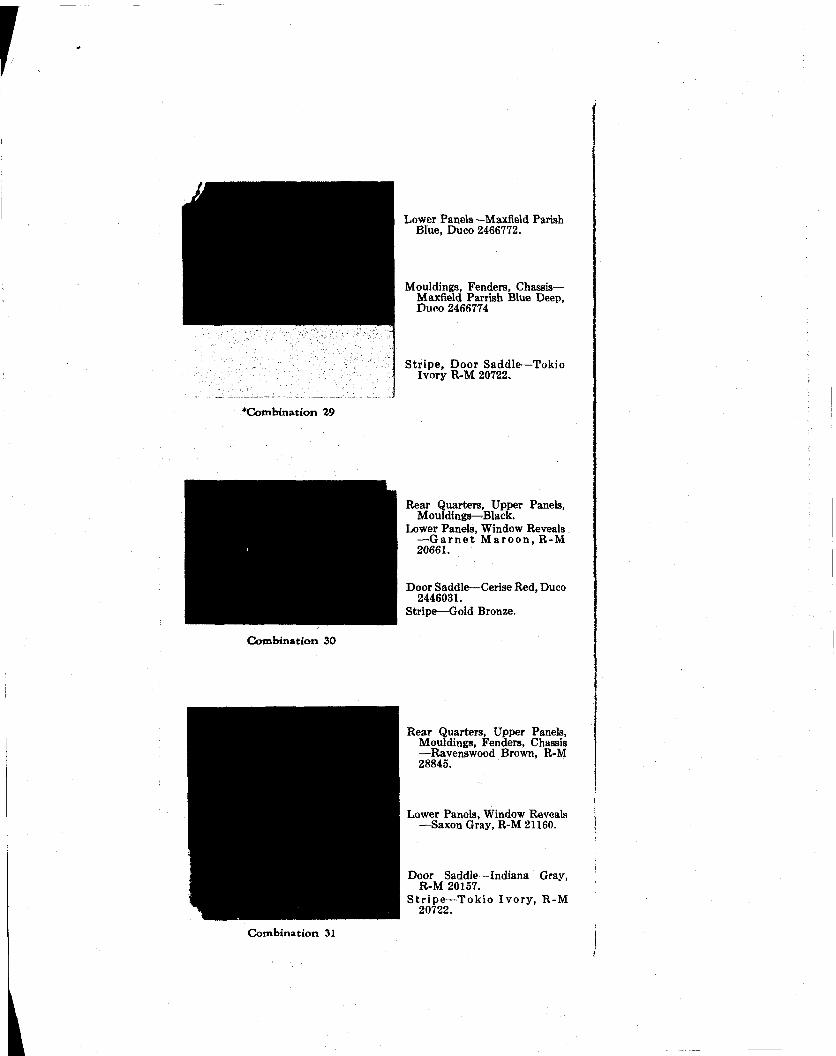
r
"Combination 29
Combination 30
Lower Panels—Maxfield Parish Blue, Duco 2466772.
Mouldings, Fenders, Chassis— Maxfield Parrish Blue Deep, Duco 2466774
Stripe, Door Saddle—Tokio Ivory R-M 20722.
Rear Quarters, Upper Panels, Mouldings—Black.
Ix>wer Panels, Window Reveals . — G a r n e t M a r o o n , R-M 20661.
Door Saddle—Cerise Red, Duco 2446031.
Stripe—Gold Bronze.
Rear Quarters, Upper Panels, Mouldings, Fenders, Chassis —Ravenswood Brown, R-M 28845.
Lower Panels, Window Reveals —Saxon Gray, R-M 21160.
Door Saddle—Indiana Gray, R-M 20157.
S t r ipe—Tokio Ivory , R-M 20722.
Combination 31
I
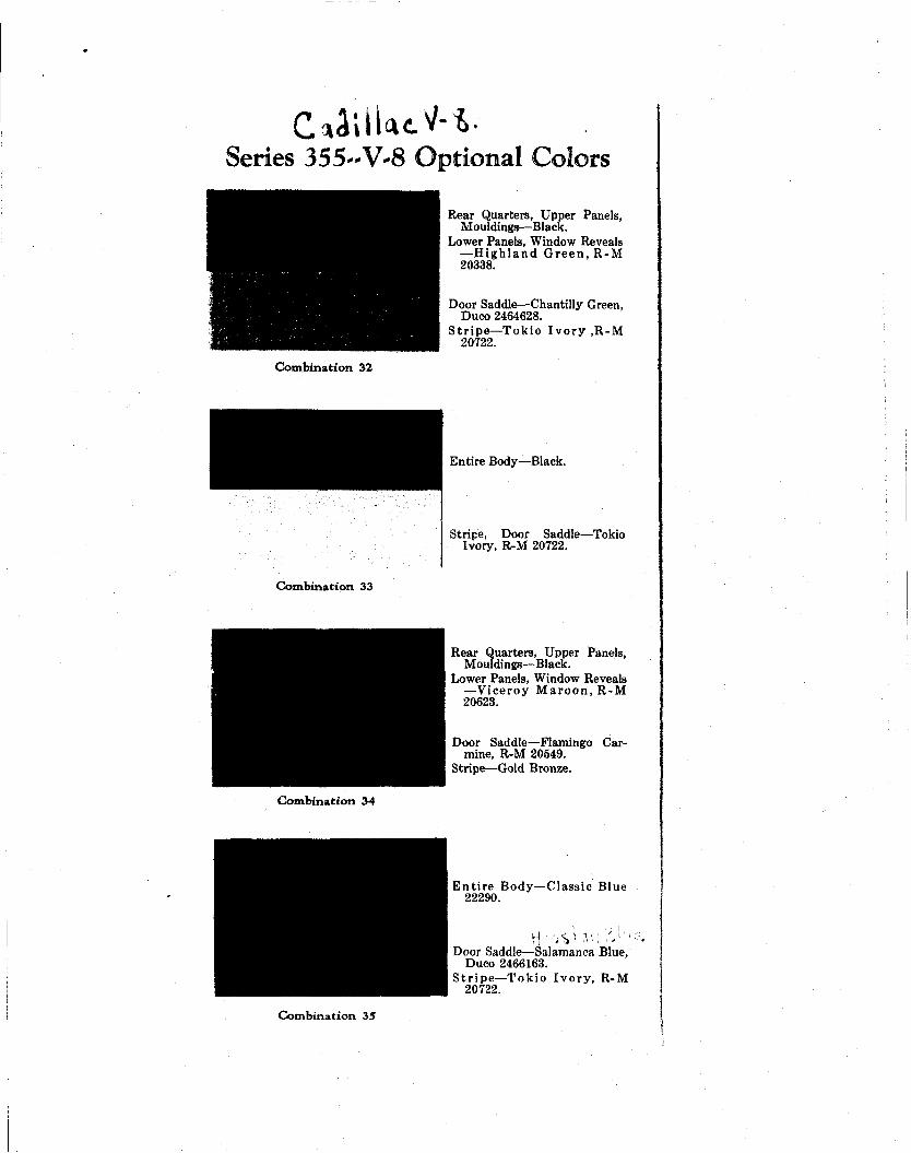
Series 355-V-8 Optional Colors
Combination 32
Combination 33
Rear Quarters, Upper Panels, Mouldings—Black.
Lower Panels, Window Reveals — H i g h l a n d G r e e n , R-M 20338.
Door Saddle—Chantilly Green, Duco 2464628.
S t r ipe—Tokio I v o r y ,R-M 20722.
Entire Body—Black.
Stripe, Door Saddle—Tokio Ivory, R-M 20722.
Rear Quarters, Upper Panels, Mouldings—Black.
Lower Panels, Window Reveals —Viceroy M a r o o n , R-M 20623.
Door Saddle—Flamingo Carmine, R-M 20549.
Stripe—Gold Bronze.
Combination 34
En t i r e Body—Classic Blue 22290.
H' i S r . ^ : .'•.•'< Door Saddle—Salamanca Blue,
Duco 2466163. S t r ipe—Tokio Ivory , R-M
20722.
Combination 35
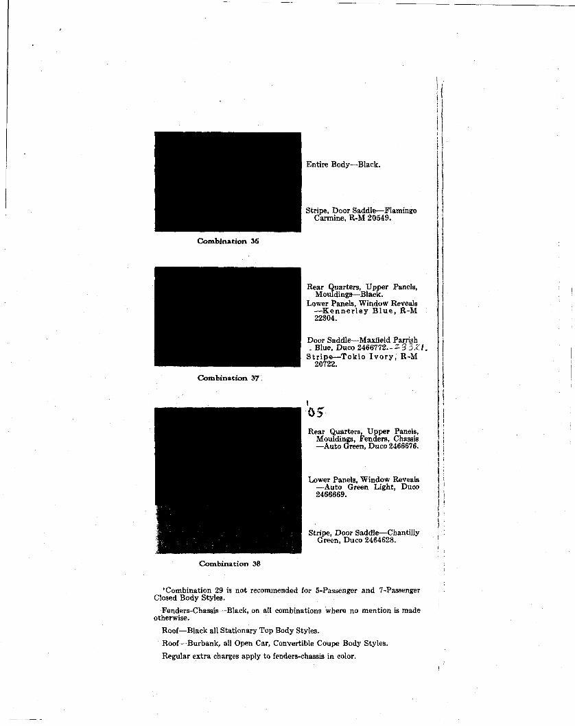
Combination 36
Combination 37
Entire Body—Black.
Stripe, Door Saddle—Flamingo Carmine, R-M 20549.
Rear Quarters, Upper Panels, Mouldings—Black.
Lower Panels, Window Reveals — K e n n e r l e y B l u e , R-M 22304.
Door Saddle—Maxfield Parrish . Blue, Duco 2466772.-Z.3 3X.I.
St r ipe—Tokio I v o r y , R-M 20722.
Rear Quarters, Upper Panels, Mouldings, Fenders, Chassis —Auto Green, Duco 2466676.
Lower Panels, Window Reveals —Auto Green Light, Duco 2466669.
Stripe, Door Saddle—Chantilly Green, Duco 2464628.
Combination 38
•Combination 29 is not recommended for 5-Passenger and 7-Passenger Closed Body Styles.
Fenders-Chassis—Black, on all combinations where no mention is made otherwise.
Roof—Black all Stationary Top Body Styles.
Roof—Burbank, all Open Car, Convertible Coupe Body Styles.
Regular extra charges apply to fenders-chassis in color.
Optional Uphols ter ing
Closed Body Styles 41T131 Taupe Mohair 43T131 Green Broadcloth 46T131 Grey Broadcloth 49T131 Taupe Broadcloth 52T131 Taupe Whipcord \ Optional, Convertible Coupe, 55T131 Gray Whipcord / All-Weather Phaeton 96T131 Tan-Brown Pin Stripe Broadcloth
Open and Convertible Body Styles 9T1331 Brown Leather
10T1331 Green Leather 11T1331 Black Leather 12T1331 Blue-Gray Leather
s