Embed Size (px)
Citation preview

Exterity AvediaStream® e2310/20, e2635/55 and e3635/55 Encoders V1.3
Administrator’s Guide
Exterity AvediaStream® e3635/e3655 Encoders

2
AvediaStream e3635/e3655 Encoder v1.3.1 Administrator’s Guide
Notices© Exterity Limited 2003-2013
This document contains information that is protected by copyright. Reproduction, adaptation, or translation without prior permission is prohibited, except as under the copyright laws.
Document Reference1300-0069-0001
Exterity Limited, Ridge Way, Hillend Industrial Park, Dalgety Bay, Fife, KY11 9JD, Scotland, UKhttp://www.exterity.com
Products Described by This GuideAvediaStream e3635 (avstr-e3635)
AvediaStream e3655 (avstr-e3655)
TrademarksAvediaStream, AvediaServer and AvediaPlayer are trademarks or registered trademarks of Exterity Limited.
Microsoft®, Windows®, and Windows Media Player® are U.S. registered trademarks of Microsoft Corporation.
HDMI, the HDMI Logo and High-Definition Multimedia Interface are trademarks or registered trademarks of HDMI Licensing LLC.
Kensington® is a U.S. registered trademarks of ACCO World Corporation.
All other trademarks are the property of their respective owners. All rights reserved.
DisclaimerThe information contained in this document is subject to change without notice.
EXTERITY LIMITED MAKES NO WARRANTY OF ANY KIND WITH REGARD TO THIS MATERIAL, INCLUDING, BUT NOT LIMITED TO, THE IMPLIED WARRANTIES OF MERCHANTABILITY AND FITNESS FOR A PARTICULAR PURPOSE. Exterity Limited shall not be liable for errors contained herein or for incidental or consequential damages in connection with the furnishing, performance, or use of this material.
WarrantyA copy of the specific warranty terms applicable to your Exterity products and replacement parts can be obtained from Exterity. To request more information or parts, email:
Safety NoticesBefore installing and operating these products, please read the safety information contained in this guide.

AvediaStream e3635/e3655 Encoder v1.3.1 Administrator’s Guide
Table of Contents
Safety Notices ......................................................................................................................................................................... 5Important Safety Instructions........................................................................................................................................... 5
USA and Canada .............................................................................................................................................................. 5EU and Others................................................................................................................................................................... 6Safety Information .......................................................................................................................................................... 6
Glossary ........................................................................................................................................7
About this Guide .......................................................................................................................9
1 Getting Started......................................................................................................................11
2 Physical Interfaces................................................................................................................13Chassis Interface.................................................................................................................................................................... 13Encoder Rear Panel Interfaces .......................................................................................................................................... 14AvediaStream e3635 Interface ......................................................................................................................................... 14
Video Inputs ...................................................................................................................................................................... 15Audio Inputs...................................................................................................................................................................... 15IR Out Socket..................................................................................................................................................................... 15
AvediaStream e3655 Interface ......................................................................................................................................... 15SDI Interface (IN) .............................................................................................................................................................. 16SDI Interface (OUT) ......................................................................................................................................................... 16Audio Inputs...................................................................................................................................................................... 16
3 Management Interfaces.....................................................................................................17Web Management Interface ............................................................................................................................................. 17Admin Interface ..................................................................................................................................................................... 18AvediaServer Director.......................................................................................................................................................... 19
4 General Device Management ..........................................................................................22About the Encoder................................................................................................................................................................ 22Device Naming....................................................................................................................................................................... 23Network Configuration ....................................................................................................................................................... 24
IP Address Configuration.............................................................................................................................................. 24Network Port Configuration ........................................................................................................................................ 25
Authentication ....................................................................................................................................................................... 25Admin Password .............................................................................................................................................................. 25SNMP.................................................................................................................................................................................... 26
5 Encoding and Streaming ...................................................................................................27Audio/Video Input – AvediaStream e3635................................................................................................................... 27Audio/Video Input – AvediaStream e3655................................................................................................................... 31Configuring Encoding Parameters.................................................................................................................................. 32
Video Configuration ....................................................................................................................................................... 33Audio Configuration....................................................................................................................................................... 35Video- or Audio-Only Mode ........................................................................................................................................ 35
3

AvediaStream e3635/e3655 Encoder v1.3.1 Administrator’s Guide
Test Pattern.............................................................................................................................................................................. 36Overlay ................................................................................................................................................................................ 37Logo Display...................................................................................................................................................................... 39
Channel Announcements .................................................................................................................................................. 42Stream Properties.................................................................................................................................................................. 44
6 Status Monitoring.................................................................................................................49Status Page Information ..................................................................................................................................................... 49Network Statistics.................................................................................................................................................................. 50
7 Maintenance ..........................................................................................................................51Specifying the TFTP Server Address ............................................................................................................................... 51Specifying the SNMP Trap Manager IP Address ......................................................................................................... 52Specifying the Time Server Address............................................................................................................................... 52Restarting the Encoder........................................................................................................................................................ 52Upgrading Firmware ............................................................................................................................................................ 53Restoring Factory Defaults................................................................................................................................................. 53Exporting/Importing Configuration Settings ............................................................................................................. 53Logging..................................................................................................................................................................................... 54
Local Logging ................................................................................................................................................................... 54Remote Logging .............................................................................................................................................................. 55
8 Troubleshooting ...................................................................................................................56
Appendix A – Serial Admin Interface Connection ....................................................... 58Cabling ...................................................................................................................................................................................... 58Adaptor Wiring....................................................................................................................................................................... 58Opening a Session ................................................................................................................................................................ 59
Appendix B – Support and Contact Information ......................................................... 60
4

AvediaStream e3635/e3655 Encoder v1.3.1 Administrator’s Guide
Safety NoticesBefore installing and operating these products, please read the safety information in this manual.
Important Safety InstructionsThere are no instructions specifically for service personnel in this document. There are no user serviceable parts inside any Exterity product. To prevent electric shock or fire hazard, do not remove cover. Refer service to qualified service personnel.
This chapter contains important safety information. If you are unsure about any of the information in the section, please contact Exterity.
USA and Canada1 Read these instructions.
2 Keep these instructions.
3 Heed all warnings.
4 Follow all instructions.
5 Do not use this apparatus near water.
6 Clean only with dry cloth.
7 Do not block any ventilation openings. Install in accordance with the instructions contained in this manual.
8 Do not install near any heat sources such as radiators, heat registers, stoves, or other apparatus (including amplifiers) that produce heat.
9 Do not defeat the safety purpose of the polarized or grounding-type plug. A polarized plug has two blades with one wider than the other. A grounding type plug has two blades and a third grounding prong. The wide blade or the third prong are provided for your safety. If the provided plug does not fit into your outlet, consult an electrician for replacement of the obsolete outlet.
10 Protect the power cord from being walked on or pinched particularly at plugs, convenience receptacles, and the point where they exit from the apparatus.
11 Only use attachments/accessories specified by the manufacturer.
12 Use only with the cart, stand, tripod, bracket, or table specified by the manufacturer, or sold with the apparatus. When a cart is used, use caution when moving the cart/apparatus combination to avoid injury from tip-over.
13 Unplug this apparatus during lightning storms or when unused for long periods of time.
The lightning flash with arrowhead symbol within an equilateral triangle is intended to alert the user to the presence of uninsulated "dangerous voltage" within the product's enclosure that may be of sufficient magnitude to constitute a risk of electric shock to persons.
The exclamation point within an equilateral triangle is intended to alert the user to the presence of important operating and maintenance (servicing) instructions in the literature accompanying the product.
Safety Notices 5

AvediaStream e3635/e3655 Encoder v1.3.1 Administrator’s Guide
14 Refer all servicing to qualified service personnel. Servicing is required when the apparatus has been damaged in any way, such as power-supply cord or plug is damaged, liquid has been spilled or objects have fallen into the apparatus, the apparatus has been exposed to rain or moisture, does not operate normally, or has been dropped.
15 Do not expose this apparatus to dripping or splashing and ensure that no objects filled with liquids, such as vases, are placed on the apparatus.
16 To completely disconnect this apparatus from the AC Mains, disconnect the power supply cord plug from the AC receptacle.
17 The mains plug of the power supply cord shall remain readily operable.
To reduce the risk of fire or electric shock, do not expose this apparatus to rain or moisture.
EU and OthersDo not proceed beyond a WARNING! notice until you have understood the hazardous conditions and have taken appropriate steps.
Safety Information
Warning: There are no user serviceable parts inside any Exterity product. To prevent electric shock or fire hazard, do not remove cover. Refer service to qualified service personnel.For 230/240 volt operation, be sure to use a harmonised grounded 3 conductor cord, rated 6 Amp minimum. Use a suitable cord for connection to the equipment and terminating in an IEC.This equipment relies upon a safety earth for operation, ensure that you always use a power cord with appropriate earth and that the inlet to which is inserted also has the appropriate earth. If in any doubt about the earth provision in your building consult a qualified electrician.Use only the dedicated power supply or cord supplied for your device.The Exterity products use ventilation holes for cooling. None of the ventilation holes should be blocked. Keep all materials at least 5cm away from all the ventilation holes.Do not expose the product to any rain or moisture.Do not use the product near a naked flame e.g. a candle.The operating conditions of the product should be 0°C-40°C with a Relative Humidity of 5 – 95%. The product should not be operated outside of these conditions.
There are no user-serviceable parts inside these products. Any servicing, adjustment, maintenance, or repair must only be performed by service-trained personnel.
Important Safety Instructions 6

AvediaStream e3635/e3655 Encoder v1.3.1 Administrator’s Guide
Glossary
The following terms and definitions are used in this document:
AAC Advanced Audio Coding - a standard for carrying digital audio.
AC-3 An audio compression scheme, also known as Dolby Digital.
AES Advanced Encryption Standard.
AV Audio/Video
Board The printed circuit board within the unit.
Composite video A type of analogue video signal where the luminance, chrominance and sync signals are all carried on a single cable. This is often referred to as CVBS.
DHCP Dynamic Host Configuration Protocol, a protocol used to allocate IP addresses to devices on an IP network
ED Enhanced Definition video, 525p 60Hz and 625p 50Hz.
H.264 A standard for video compression, also known as MPEG-4 Part 10 and MPEG-4 AVC (Advanced Video Coding).
HD High Definition video, 720p, 1080i and 1080p (1080p capability only on specified products).
HD AV A digital interface for connection to devices equipped with DVI (DVI-to-HDMI adaptor required) and HDMI connections.
HDCP High-bandwidth Digital Content Protection is designed to prevent copying of digital audio and video content passing across Digital Visual Interface (DVI) and High-Definition Multimedia Interface (HDMI) connections.
HDMI™ High-Definition Multimedia Interface, a compact interface for transmission of uncompressed digital audio and video content.
IGMP Internet Group Management Protocol, a protocol used to manage multicast traffic on an IP network
Input Physical interface on Exterity equipment that receives Audio/Video from a source.
IP Internet Protocol, a protocol used for communicating data across a network using the Internet Protocol Suite, also referred to as TCP/IP.
IP TOS The Type of Service (TOS) field is a six-bit Differentiated Services Code Point (DSCP) field and a two-bit Explicit Congestion Notification field.
MPEG A family of compression methodologies for audio and video.
MPEG Transport Stream
A communications protocol enabling multiplexing of digital audio, video and data which is specified in MPEG-2 Part 1, Systems (ISO/IEC standard 13818-1).
NTP Network Time Protocol, used for synchronizing the clocks of computer systems
RGBHV Red (R), Green (G), Blue (B) Component analogue video signal with horizontal (H) and vertical (V) synchronisation, all on separate lines. It is most commonly used in the VGA connection for computer monitors.
RGBS A specific type of RGB where the video sync signal is carried on a fourth cable.
RTP Real-time Transport Protocol, a protocol used to carry real time data on an IP network
SAP Session Announcement Protocol, a protocol used to advertise the presence of multicast sessions on an IP network
SD Standard Definition video, 525i 60Hz and 625i 50Hz.
SDI Serial Digital Interface (SDI), a high speed serial interface that carries uncompressed video with the option of embedded audio. It is specified as SMPTE 259M (270MB/s SD-SDI), SMPTE 292M (1.485Gbit/s HD-SDI), and SMPTE 424M (2.97Gbits/s 3G-SDI).
Source A device that can provide an Audio/Video input to the encoder.
7

AvediaStream e3635/e3655 Encoder v1.3.1 Administrator’s Guide
SVC Scaleable Video Coding, part of the H.264/MPEG-4 AVC video compression standard.
Telnet Telnet is a network protocol that enables one computer to communicate with another over an IP network.
TFTP Trivial File Transfer Protocol, a simple file transfer protocol used on IP networks.
UDP User Datagram Protocol, a transport protocol in the TCP/IP suite, which provides a connectionless transport mechanism with low overhead.
Unit Exterity product, for example, an AvediaStream e36xx unit containing a printed circuit board.
YPbPr A type of Component analogue video signal consisting of a colourless Component (luminance), combined with two colour-carrying components (chrominance). This is commonly referred to simply as “Component”.
8

9
AvediaStream e3635/e3655 Encoder v1.3.1 Administrator’s Guide
About this Guide
This guide explains how to set up, use and manage the AvediaStream e3635/55 products, commonly referred to as “encoders”.
Encoders are network devices that accept a signal from an AV device, for example, a DVD player or a proprietary set-top box, and output it as an MPEG transport stream over an IP network.
AudienceThis manual is intended for use by systems integrators or systems administrators who are installing and setting up Exterity products. The manual assumes that readers are familiar with installing and configuring network-based products.
ScopeThis edition of the manual refers to version 1.3.1 of firmware for the encoders.
Associated DocumentationThis guide should be used in conjunction with the following manuals.
AvediaStream Installation Guide 1300-0018-0001
AvediaServer - Managing your IPTV System - Administrator’s Guide 1300-0052-0001

Exterity AvediaPlayer r92xx Series Receiver version 3.2
Section 1 Getting Started
This section contains information on the following:
• An overview of the steps required to get the encoder up and running
• The physical interfaces of the encoders
• The different methods you can use to manage the encoder.

1 Getting Started
AvediaStream Encoders create a single IPTV stream on your Ethernet IP network from the output of various video devices. You can use them to distribute the output from a variety of Standard Definition and High Definition AV devices such as video cameras, DVD players, set-top boxes and professional SDI feeds.
AvediaStream e36xx Encoders accept SD and HD content inputs, producing an IPTV stream with resolution up to 1080i 50/60Hz. They also allow scaling of any input to any output resolution and frame rate up to 1080i 50/60Hz.
You must carry out the following steps for the encoder to perform correctly:
1 Install in an AvediaStream Chassis
Insert the encoder into an AvediaStream c1101, c1103, or c1110 chassis which provides power and enables connection to your network. For more information, refer to the AvediaStream Installation Guide.
2 Connect the AV Source
Before the encoder can stream audio/video on the network, you must first connect an AV source. See Chapter 2, "Physical Interfaces" for details on how to connect your AV equipment to the encoder.
3 Connect to the network
Connect the encoder to the network. For more information, see the AvediaStream Installation Guide.
4 Power the encoder
Connect the encoder to a power source. For more information, see the AvediaStream Installation Guide.
5 Configure the encoder’s IP address
By default, the encoder requires a DHCP Server to be available on the network to assign it an IP address.
If you need to assign a static IP address, there are two methods of doing this:
• Use the serial Admin Interface to configure the IP address. For more information refer to “Admin Interface” on page 19.
• Temporarily set up a DHCP server on an isolated network. Once an IP address has been assigned, you can configure a static IP address using the Web Interface. For more information refer to “Network Configuration” on page 22.
Note: Allocating a static IP address allows continued operation without a DHCP Server.
6 Name the encoder
Provide a name and location for the encoder so you can easily identify it in the future. To do this, use the AvediaServer Director application or the Web Interface General Page.
7 Configure audio/video input
The device starts encoding and streaming automatically when an appropriate AV source is connected. It may be necessary to configure the type of video source connected. Refer to Chapter 5, "Encoding and Streaming" for more information.
11

AvediaStream e3635/e3655 Encoder v1.3.1 Administrator’s Guide
8 Configure encoding options
The device starts encoding automatically when an appropriate source is connected. Some encoding aspects can be configured if required. For more information refer to Chapter 5, "Encoding and Streaming".
9 Configure streaming options
The encoder starts streaming (transmitting an MPEG transport stream on the IP network) automatically when an appropriate source is connected. Some aspects of the stream can be configured if required. For more information refer to Chapter 5, "Encoding and Streaming".
Note: If the encoder does not start streaming automatically, check that the “Stream on Boot” checkbox on the Stream web page is checked.
10 Configure Test Patterns and Overlays (optional)
Specify solid colours/test patterns and/or logo and text overlays if you want to carry out system testing using common test patterns or add logos and text overlays to be displayed.
For more information refer to “Test Pattern” on page 36.
11 Configure channel announcements
The encoder uses SAP (Session Announcement Protocol) to announce its stream (channel) to receiving devices. Included in the announcements are the name of the channel and the multicast address and port on which the stream is sent. This is done automatically once the device is up and running.
You can configure channel announcements to suit your requirements. For more information refer to “Channel Announcements” on page 42.
12 Check the status
You can check the operating status of the encoder and check that it is transmitting data at the rate expected by the streaming settings. For more information refer to Chapter 6, "Status Monitoring".
12

2 Physical Interfaces
AvediaStream Encoders can operate in any of the following chassis:
• AvediaStream c1101
• AvediaStream c1103
• AvediaStream c1110
AvediaStream Encoders have AV interfaces on their rear panels, while their edge connectors enable them to access network and admin ports via the chassis front panel.
Caution: Take care not to touch the edge connector as static electricity might damage the product. Handle by the enclosure only and insert as soon as possible into the chassis.
Chassis InterfaceThe encoder module provides the following interfaces over its edge connector to the chassis:
• Ethernet interface (10/100Mbps)
• Admin Interface
• Status LEDs
• Power supply
The actual physical interfaces can be found on the chassis front panel. Please refer to the relevant AvediaStream Installation Guide for further details.
Heartbeat LEDThe heartbeat LED (marked H/B) on the AvediaStream chassis front panel provides an indication of the current state of the unit without using any of the management interfaces. The LED behaviour is described in Table 1.
Table 1 Heartbeat LED patterns
Pattern (approx rate) Description
Flashing rapidly Running power-on self tests
Solid On Booting operating system, takes approximately 10-20 seconds
Four times a second Waiting for DHCP IP address allocation
Once a second Indicates unit is running normally
Alternatively < 1 sec, > 10 secs Upgrading
Chassis Interface 13

AvediaStream e3635/e3655 Encoder v1.3.1 Administrator’s Guide
Encoder Rear Panel InterfacesThe AvediaStream Encoders support the following inputs and outputs.
1 HD AV Audio is only available when HD AV video is selected.
AvediaStream e3635 InterfaceThe AvediaStream e3635 encoder provides video and audio inputs and an IR output as shown in Figure 1.
Figure 1 AvediaStream e3635 Encoder – rear panel
Table 3 Encoder rear panel interfaces
Video Inputs e3635 e3655
HD Component
SD Component
HD AV
RGBHV
SD-SDI (SMPTE 259M)
HD-SDI (SMPTE 292M)
3G-SDI (SMPTE 424M)
Audio Inputs
Unbalanced
S/PDIF
HD AV embedded Audio1
SDI Embedded Audio
IR Out Socket
Encoder Rear Panel Interfaces 14

AvediaStream e3635/e3655 Encoder v1.3.1 Administrator’s Guide
Video InputsThe following video input types are supported:
• HDMI (HD AV) with audio – Connect an HDMI source to the encoder using a standard HDMI Type A plug connector to connect to the HD AV input.
Note: Content protected by HDCP cannot be streamed on the HD AV interface.
Note: You can use a DVI-to- HDMI converter/cable to connect a DVI source to the HD AV input.
• VGA (RGBHV) – Connect an RGBHV source such as a VGA-equipped PC or signage equipment using a standard VGA monitor cable (fitted with 3-row 15-pin DE-15 plug) to connect to the RGBHV input.
• YPbPr – Connect a YPbPr component source using a Component-to-VGA adaptor (female) to connect to the RGBHV input.
Audio Inputs• Analog - Inputs marked Left and Right, connection using RCA (Phono) cables.
• S/PDIF – Input marked SPDIF, connection using an RCA (Phono) cable supporting uncompressed 48kHz digital audio or AAC audio.
• HD AV audio – When HD AV video input is selected.
IR Out SocketThis is intended to control the attached AV device. The associated IR transmitter is supplied with the unit.
Note: The IR function is not available with this firmware release.
AvediaStream e3655 InterfaceThe AvediaStream e3655 encoder provides an SDI video input with embedded or S/PDIF audio inputs. SDI Loop-through is also available. Connections are shown in Figure 2 below.
Figure 2 AvediaStream e3655 Encoder – rear panel
AvediaStream e3655 Interface 15

AvediaStream e3635/e3655 Encoder v1.3.1 Administrator’s Guide
There are three physical interfaces:
• Single input BNC (SDI video, SDI video with embedded audio)
• Single output ‘Loop-though’ BNC (No Output, Input loop-through, or Re-clocked Input Loop-through)
• RCA Phono (S/PDIF audio). This allows you to encode audio from the SDI interface or to use the S/PDIF interface as the audio source.
Note: The BNC interface is marked with ASI/SDI as this interface is common to the SDI Encoder and ASI Gateway. The interface is committed to SDI or ASI in the factory and cannot have its function changed in the field.
The AvediaStream e3655 is fitted with 2 LEDs with following functions:
• Left – The Red LED is lit when signal errors are detected on the input signal.
• Right – The Green LED is lit when the encoder detects SDI, HD-SDI or 3G-SDI input signals.
SDI Interface (IN)The SDI interface supports the following:
• SMPTE 259M (270Mbits/s SD-SDI)
• SMPTE 292M (1.485Gbit/s HD-SDI)
• SMPTE 424M (2.97Gbits/s 3G-SDI).
Connect an SD-SDI, HD-SDI, or 3G-SDI input using a BNC connector. The following resolutions and frame rates are supported:
• 525i 60Hz and 625i 50Hz
• 720p 50Hz/59.94Hz/60Hz
• 1080i 50Hz/59.94Hz/60Hz
• 1080p 23.98Hz/24Hz/50Hz/59.94Hz/60Hz
SDI Interface (OUT)The SDI (OUT) interface is a loop-through interface to enable you to connect the same SDI input to another device. Connect using a BNC connector.
This output is disabled by default, and can be configured via the web interface Input page.
Caution: Do not connect the output interface to any other output interface as this may damage the unit.
Audio Inputs• Embedded SDI stereo audio (stereo pair selectable from one of 8 pairs embedded within the
SDI video stream)
• S/PDIF digital audio (RCA phono) (PCM 48kHz)
This allows you to encode audio from the SDI interface or to use the S/PDIF interface as the audio source.
Note: Only 48kHz PCM audio is supported by the encoder. If a different sample rate is detected, “unsupported sampling rate” is displayed on the Status page.
AvediaStream e3655 Interface 16

3 Management Interfaces
The encoder has three management interfaces, as follows:
• Web Management Interface
• Admin Interface
• AvediaServer Director
Note: Each encoding module in a chassis must be configured independently.
Web Management InterfaceYou can manage all aspects of the encoder’s functionality using the Web Management Interface, which is supported by Microsoft Internet Explorer and Mozilla Firefox.
Open the Web Management Interface as follows:
1 Enter the IP address of the encoder directly into your browser, or click the encoder’s name in the AvediaServer Director application as shown on page 19.
2 When prompted, enter the username and password. The default login details are:
Username: admin
Password: labrador
Figure 3 Login window
Note: You can also change the admin password using the Admin Interface. For more information refer to “Admin Interface” on page 18.
Web Management Interface 17
AvediaStream e3635/e3655 Encoder v1.3.1 Administrator’s Guide
3 The Web Management Interface opens in your browser, as shown in Figure 4:
Figure 4 Web management interface
4 Use this menu to navigate through the pages, changing settings as required. Click Apply on each page to save your changes.
Note: For security reasons, we recommend that you change the administrator password as soon as possible. Please see “Authentication” on page 26 for details on how to do this.
Admin InterfaceIn certain circumstances it may not be possible to manage the encoder via the Web Management Interface. For these situations, a text-based Admin Interface is provided, which is available via the serial interface (marked ‘ADM’ on the chassis front panel) or via telnet.
See Appendix A, "Serial Admin Interface Connection" for details of how to connect to the serial admin port.
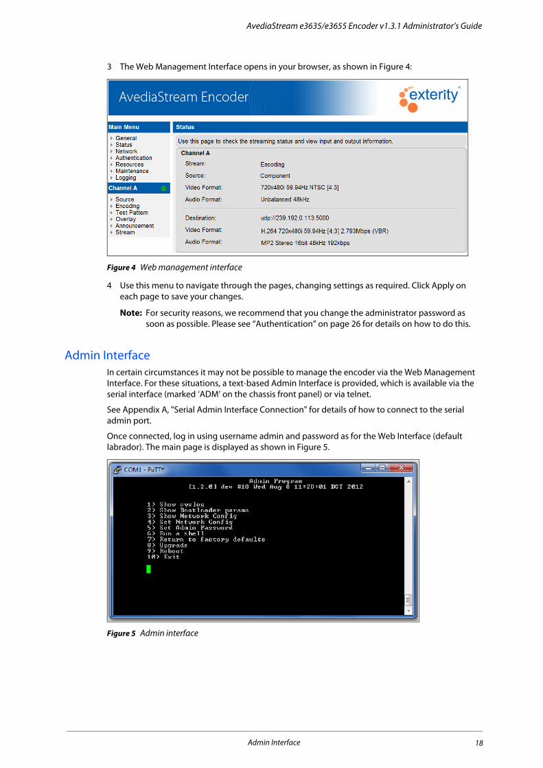
Once connected, log in using username admin and password as for the Web Interface (default labrador). The main page is displayed as shown in Figure 5.
Figure 5 Admin interface
Admin Interface 18

AvediaStream e3635/e3655 Encoder v1.3.1 Administrator’s Guide
The options are as follows:
AvediaServer DirectorThe AvediaServer Director, as shown in Figure 6, is used for device discovery and management and is an integral part of the AvediaServer platform from version 3.2.0 onwards. The AvediaServer Director uses SNMP to manage a subset of device functionality and can also be used to open the Web Management Interface of the encoder.
Figure 6 AvediaServer Director
The AvediaServer Director can perform the following actions on the encoder:
• Set Name - Specify the encoder name.
• Set Location – Specify the encoder location.
• Reboot – Re-start the encoder.
• Ping – Ping the encoder.
• Upgrade Firmware – Upload new device firmware.
• Factory Reset – Set the encoder back to factory default configuration.
• Export Config – Export the current configuration for archiving or applying to another device.
• Import Config – Restore the encoder to a previously saved configuration.
1 Show syslog Displays the device log file.
2 Show Bootloader params Displays the internal configuration used by the bootloader.
3 Show Network Config Displays the IP addressing information of the device.
4 Set Network Config Allows the administrator to set the IP address of the device.
5 Set Admin Password Allows the administrator to change the admin password for the Admin and Web Interfaces.
6 Run a shell Allows the administrator to run a shell as admin.
7 Return to factory defaults Allows the administrator to set all configuration to factory defaults.
8 Upgrade Allows the administrator to specify the TFTP server and initiate a firmware upgrade.
9 Reboot Restarts the device.
AvediaServer Director 19

AvediaStream e3635/e3655 Encoder v1.3.1 Administrator’s Guide
• Set TFTP Server – Specify the IP address of the TFTP server to be used.
• Set Syslog Server – Specify the IP address of the Syslog server to be used.
To start the encoder Web Interface with AvediaServer Director:
1 Open the AvediaServer Web Interface and start the Director application.
2 Select Encoder from the Device drop-down list to display only encoders.
3 Use the column sort functions to help locate the encoder you want to configure.
4 Click the required encoder Name hyperlink to launch the Web Interface login window as shown in Figure 3.
5 Enter the admin login credentials to display the Web Interface.
To open the Admin Interface via telnet with AvediaServer Director:
1 Open the AvediaServer Web Interface and start the Director application.
2 Select Encoder from the Device drop-down list to display only encoders.
3 Use the column sort functions to help locate the encoder you want to configure.
4 Click the required encoder icon hyperlink ( ) in the Name column to launch the Admin Interface window as shown in Figure 5.
AvediaServer Director 20

Exterity AvediaPlayer r92xx Series Receiver version 3.2
Section 2 Encoder Configuration
This section contains information on the following:
• General device management, including naming the encoder, network configuration and authentication.
• How to use the encoders to take analogue AV input signals and convert them to an IPTV stream.

4 General Device Management
This chapter contains the following information:
• About the Encoder
• Device Naming
• Network Configuration
• Authentication
All procedures described in this section assume that you are running the Web Management Interface as described in Chapter 3, "Management Interfaces".
About the EncoderThe General page in the Web Interface displays specific information about the encoder (Figure 7). Much of this information is useful for identifying the software and hardware revisions in use in this module. If contacting technical support regarding a problem with the device, it can be useful to provide all this information.
• Product Type: The product variant.
• Software version: The version of software (often known as firmware) running on this device.
• Description: A detailed version description identifying when the software was built.
• Serial number: The MAC address of the unit.
• IP Address: The IP address being used by the unit.
• Hardware Type: The exact type of hardware module.
• Date: The current date and time zone.
• Uptime: The length of time this device has been running since the last restart.
• Board Temperature: The current temperature of the device.
About the Encoder 22

AvediaStream e3635/e3655 Encoder v1.3.1 Administrator’s Guide
Figure 7 AvediaStream – e3635 General Page
Device NamingYou can assign a name and location to the encoder which can help identify it in a management application, such as AvediaServer Director.
To specify the name and location:
1 Click General.
2 Enter a name and location as required in the Name and Location fields.
3 Click Apply.
Note: You can also configure the name and location using the Name and Location actions in the AvediaServer Director application.
Device Naming 23

AvediaStream e3635/e3655 Encoder v1.3.1 Administrator’s Guide
Network ConfigurationThis section describes encoder options relating to network connections. These options are all available from the Network page shown in Figure 8.
Figure 8 Network Page
IP Address ConfigurationYou can configure the encoder to obtain an IP address automatically using DHCP, or you can specify static addressing information i.e. IP address, subnet mask and default gateway. The default is DHCP.
Note: An IP addressing change may take a short time to come into effect. The device starts using the new IP address automatically - no reboot is necessary.
To configure the encoder to be allocated an IP address automatically:
1 Click Network.
2 Select DHCP (Automatic) from the IP Address Settings drop-down list.
3 Click Apply.
To configure a static IP address:
1 Click Network.
2 Select Static (use below) from the IP Address Settings drop-down list.
3 Specify values for IP Address, Subnet Mask, Default Gateway and DNS Server.
4 Click Apply.
Network Configuration 24

AvediaStream e3635/e3655 Encoder v1.3.1 Administrator’s Guide
Network Port ConfigurationThe encoder can automatically negotiate any combination of 10/100 Mbps and half/full duplex with an Ethernet switch. It is also possible to disable auto-negotiation, resulting in a fixed setting of 100Mbps full duplex (100FD).
The default setting is On (Auto-negotiation enabled).
Note: It is important to ensure the encoder settings match the settings on the switch port to which it is connected. For example, if auto-negotiation is enabled on the encoder, it must also be enabled on the switch. If auto-negotiation is disabled, a fixed setting of 100FD must be configured on the switch. Failure to do this may result in dropped packets, which in turn, may cause poor quality video output at the client device.
In practice this means the encoder and the connected network switch should be configured for operation as follows:
• Auto-negotiation enabled on both the encoder and the connected network switch, or
• Auto-negotiation disabled on both the encoder and the connected network switch, and a fixed setting of 100FD (Full Duplex) configured on the switch.
We do not recommend connecting the encoder to a half duplex Ethernet port.
To enable/disable Ethernet auto-negotiation:
1 Click Network.
2 In the Network Port Configuration section, choose On or Off as appropriate from the Auto-negotiation drop-down list.
3 Click Apply.
Authentication
Admin PasswordYou can control access to the Web Interface and Admin Interface by changing the password. These options are all available from the Authentication page in the Web Interface shown in Figure 9. The user name is always “admin”.
Figure 9 Authentication Page
Authentication 25

AvediaStream e3635/e3655 Encoder v1.3.1 Administrator’s Guide
To change the admin password:
1 Click Authentication.
2 Enter the required password in both fields.
3 Click Apply.
SNMPSNMP is used by applications such as the AvediaServer Director application to manage a subset of the encoder functions and configuration. It is possible to completely disable the use of SNMP; however, if you disable SNMP on the encoder, management applications such as the AvediaServer Director will not be able to communicate with it.
To configure SNMP community strings:
1 Click Authentication.
2 Enter the required read/write and read-only community strings in the appropriate boxes.
3 Click Apply.
To enable/disable SNMP control:
1 Click Authentication.
2 Select or deselect the Enable SNMP Agent box as required (default: enabled).
3 Click Apply.
Authentication 26

5 Encoding and Streaming
This chapter describes how to use the encoders to take the analogue or digital AV input signals and convert them to an IPTV stream. All procedures described here assume that you are using the Web Interface, as described on page 15, to configure the AvediaStream Encoder.
Configuration procedures are either individually described in the following sections or with the differences highlighted where appropriate.
Audio/Video Input – AvediaStream e3635Audio/Video input is configured from the Source page on the web interface as shown in Figure 10. The video and audio controls are shown in Figure 11.
Figure 10 AvediaStream e3635 – Source Page
Figure 11 AvediaStream e3635 – Source Page manual controls
Audio/Video Input – AvediaStream e3635 27

AvediaStream e3635/e3655 Encoder v1.3.1 Administrator’s Guide
Video InputYou must select the Video Input to match the applied video input and physical connection to the encoder. Valid input options are HDAV, RGBHV and Component (YPbPr). For more information about the video input connections refer to “AvediaStream e3635 Interface” on page 14. The default value for the e3635 is HDAV.
To specify the video input:
1 Click Source.
2 Choose an option from the Video Input drop-down list.
3 Click Apply.
Video Aspect Ratio (Component and RGBHV only)If you select the Component or RGBHV video input you can also specify the aspect ratio of the input video signal. This setting is not available when HDAV is selected. The default is Automatic.
To specify the HD video format:
1 Click Source.
2 With Component or RGBHV as the configured Video Input, select 4:3, 16:9 or Automatic from the Video Aspect Ratio drop-down list.
3 Click Apply.
Preferred Input Resolution (RGBHV and HDAV only)Devices with HDMI and RGBHV inputs make EDID (Extended Display Identification Data) available to source devices, for example a camera or a PC, to advertise its supported capability and preferred settings. You can set the preferred resolution for the AvediaStream Encoder when RGBHV or HDAV is the selected input, causing the source device to output at the specified value when connected. The default is 1080p 24Hz.
Note: Some devices ignore EDID content and output at their configured resolution and must be manually configured if a specific resolution and frame rate is required.
To specify the Preferred Input Resolution:
1 Click Source.
2 With RGBHV or HDAV as the configured video input, select the required value from the Preferred Input Resolution drop-down list.
3 Click Apply.
24/60Hz Frame RateHD material can either be true 24/60Hz, or may be adjusted by a 1/1.001 divider to give 23.98Hz or 59.94Hz. For consistent, stable operation the AvediaStream Encoder setting must match that of the applied video signal.
Frame Rate sets the AvediaStream Encoder frame rate to match that of the applied video input signal. Valid options are 24.00/60.00Hz or 23.98/59.94Hz. The default is 23.98/59.94Hz.
To specify the frame rate:
1 Click Source.
2 Select the required value from the 24/60Hz Frame Rate drop-down list.
3 Click Apply.
Audio/Video Input – AvediaStream e3635 28

AvediaStream e3635/e3655 Encoder v1.3.1 Administrator’s Guide
Force VGA ResolutionA 525p signal has 480 active lines and hence cannot be distinguished from a VGA (640x480 pixel) signal. The setting allows you to specify the signal applied to the input, ensuring it is encoded correctly. Select Force VGA Resolution when a VGA output from a PC is applied, and Force 525p resolution when a 525 line TV signal is applied. The default is Force 525p resolution.
To specify the forced resolution:
1 Click Input.
2 Choose the required option from the Force VGA Resolution drop-down list.
3 Click Apply.
Picture ControlsPicture controls allow you to use the default brightness, contrast, saturation, and hue settings of the video images in the streamed output from the encoder, or to manually adjust each parameter if required. The default is Automatic.
Figure 12 Picture controls
1 To specify the picture control settings:
2 Click Source.
3 Select Manual from the Picture Control drop-down list.
4 Click the Video Brightness slider and drag it to the required level, or click in the entry field and enter a value between -128 and 127. The default value is 0, no adjustment.
5 Click the Video Contrast slider and drag it to the required level, or click in the entry field and enter a value between 0 and 199. The default value is 100, no adjustment.
6 Click the Video Saturation slider and drag it to the required level, or click in the entry field and enter a value between 0 and 199. The default value is 100, no adjustment.
7 Click the Video Hue slider and drag it to the required level, or click in the entry field and enter a value between 0 and 180. The default value is 0, no adjustment.
8 Click Apply.
Audio/Video Input – AvediaStream e3635 29

AvediaStream e3635/e3655 Encoder v1.3.1 Administrator’s Guide
Audio InputAudio input specifies the type of audio applied to the encoder. Valid settings are Analog, S/PDIF, and HDAV. HDAV audio is not available for RGBHV video input. Refer to “AvediaStream e3635 Interface” on page 14 for more information about audio connections. The default setting is S/PDIF.
To specify the audio input:
1 Click Source.
2 Choose an option from the Audio Input drop-down list.
3 Click Apply.
Audio Volume (Analogue only)With analogue configured for the Audio Input, you can adjust the Audio Volume between 0 and 31. The Default is 24.
Figure 13 Audio Control
To specify the audio volume:
1 Click Source.
2 Choose Analog from the Audio Input drop-down list.
3 Click on the Audio Volume slider and drag it to the required level, or click in the entry field and enter a value between 0 and 31. The default value is 31, no adjustment.
4 Click Apply.
HDCPHigh-bandwidth Digital Content Protection (HDCP) is a form of copy protection commonly used with devices equipped with digital connection interfaces such as DisplayPort, HDMI, and DVI. Consumer equipment such as Blu-ray players, most up-scaling DVD players and some cable/satellite/terrestrial set top boxes protect HDMI outputs when copy-protected content is being played. Some PCs also protect their HDMI/DVI outputs with HDCP.
AvediaStream e3635 encoders cannot encode copy protected material. When copy protected content is applied to the encoder across an HDCP protected connection the protected connection is indicated on the web interface Status as shown in the following example:
• Stream: Unsupported HDCP protected input
• Video Input: HD AV (720p 59.940Hz - HDCP protected content)
Audio/Video Input – AvediaStream e3635 30

AvediaStream e3635/e3655 Encoder v1.3.1 Administrator’s Guide
Audio/Video Input – AvediaStream e3655Audio/Video input is configured from the Source page on the web interface as shown in Figure 14.
Figure 14 AvediaStream e3655 – Source Page
SDI InputAvediaStream e3655 encoders support the following inputs:
• SDI SMPTE 259M
• SDI SMPTE 292M
• SDI SMPTE 424M
They are compatible with SDI sources which have output frame rates of 23.98Hz, 24Hz, 50Hz, 59.94Hz, and 60Hz.HD material can either be true 24/60Hz, or may be offset by a 1/1.001 divider to give 23.98Hz or 59.94Hz. The encoders automatically detect the frame rate and no configuration is required.
SDI Loop-throughTo enable the chaining together of additional equipment, the SDI input signal can be presented at the SDI output of the AvediaStream e3655 encoders using the Loop-through function. When Loop-through is selected, the SDI signal at the input is passed to the output without modification. When Re-clocked loop-through is selected, the input signal is processed to reduce jitter.
Tip: While the Re-clocked loop-through process delivers a better quality signal at the output, the timing is affected and the output signal is out of phase with the input. Simple Loop-through is more likely to suit environments where the timing of different SDI feeds is critical.
The default setting is Disabled. To specify the SDI Loop-through:
1 Click Source.
2 Choose an option from the SDI Loop-through drop-down list.
3 Click Apply.
Audio InputAudio input sets the type of audio input to the encoder. SDI Embedded and S/PDIF can be selected. If SDI Embedded is selected, the encoder de-embeds the audio from the SDI stream. The default is SDI Embedded.
To specify the audio input:
1 Click Source.
2 Choose an option from the Audio Input drop-down list.
3 Click Apply.
Audio/Video Input – AvediaStream e3655 31

AvediaStream e3635/e3655 Encoder v1.3.1 Administrator’s Guide
SDI Audio Group and ChannelWhen Embedded is selected, the module extracts the audio from the SDI stream. Configure the Group and Channel settings to select the required audio from the 8 possible stereo pairs. The default setting is Group 1 and Channels 1/2.
To specify the audio group:
1 Click Source.
2 Choose an option from the Audio Group and Audio Channel drop-down lists.
3 Click Apply.
Configuring Encoding ParametersWhen configuring encoding parameters, please note the following:
• The output video stream can be encoded to either MPEG-2 or H.264 (MPEG-4 Part 10) standard.
• Scaling capabilities enable the input signal to be output in a variety of resolutions and frame rates with stream bit rates ranging between 128kbps and 20Mbps using either Constant or Variable Bit Rate encoding.
• GOP Structure can also be specified manually.
• You can also choose MP2 (MPEG-1 Layer 2) or AAC (Advanced Audio Coding) audio encoding.
Encoding parameters are configured on the Encoding page as shown in Figure 15.
Figure 15 AvediaStream e3655 Encoding Page – default settings
Configuring Encoding Parameters 32

AvediaStream e3635/e3655 Encoder v1.3.1 Administrator’s Guide
Video Configuration
MPEG Standard The H.264 CODEC can provide good video quality at substantially lower bit rates than previous standards such as MPEG-2 and MPEG-4 Part 2. Select the appropriate standard for your display devices. The default is H.264.
To configure the MPEG standard:
1 Click Encoding.
2 Select MPEG-2 or H.264 from the MPEG Standard drop-down list.
3 Click Apply.
Audio Only ModeTo take an audio only input and stream this as an audio channel:
1 Click Encoding.
2 Select None from the MPEG Standard drop-down list.
3 Click Apply.
Bit Rate ModeEncoders can be configured to transmit the transport stream with Constant Bit Rate (CBR) or Variable Bit Rate (VBR). The values range from 128 kbps to 20 Mbps. The default setting is Constant.
To select and configure CBR:
1 Click Encoding.
2 Select Constant from the Bit Rate Mode drop-down list.
3 Select a value from 128 kbps to 20 Mbps from the Bit Rate drop-down list.
4 Click Apply.
To select and configure VBR:
1 Click Encoding.
2 Select Variable from the Bit Rate Mode drop-down list.
3 Select a value from 128 kbps to 20 Mbps from the Average Rate drop-down list.
4 Select a value from 128 kbps to 20 Mbps from the Maximum Rate drop-down list.
5 Click Apply.
In addition to the bit rates available from the drop-down lists, you can configure any value between the max/min limits by directly entering the required value in the Bit Rate fields. For example; to specify 6 Mbps, enter a value of 6000000. This can be applied in both Constant and Variable bit rate modes.
Aspect RatioTo specify the aspect ratio:
1 Click Encoding.
2 Select Unchanged, 4:3 or 16:9 from the Aspect Ratio drop-down list.
3 Click Apply.
Configuring Encoding Parameters 33

AvediaStream e3635/e3655 Encoder v1.3.1 Administrator’s Guide
Frame RateLowering the frame rate enables you to reduce the bandwidth required in the output stream. However, this may affect the picture quality on fast action content. The default is 50Hz.
To specify the frame rate:
1 Click Encoding.
2 Select Unchanged, or a value between 60Hz and 12.5Hz from the Frame Rate drop-down list.
3 Click Apply.
Output Resolution Lowering the resolution to suit the output device enables you to reduce the bandwidth required in the output stream. However, this may affect the picture quality on high resolution displays. The default is No Scaling.
To specify the output resolution:
1 Click Encoding.
2 Select No Scaling, or a value lower than the input stream from the Output Resolution drop-down list.
3 Click Apply.
H.264 ProfileThe H.264 standard defines sets of capabilities, called profiles. Each profile specifies a set of encoding conditions that meet the diverse quality and bandwidth requirements ranging from HDTV broadcast services to security CCTV systems. You can select the following profiles:
• High – H.264 specified High Profile (HiP) providing the highest picture quality, mainly used for HD broadcast and disc storage.
• Main – H.264 specified Main Profile (MP), used mainly for SD broadcast.
• Baseline – H.264 specified Baseline Profile (BP), used mainly where greater robustness of the transport stream is required.
• Auto – default – automatically selects BP for SD input and HiP for HD input.
Tip: Automatic (HiP) should be suitable in most scenarios. However, for sub-SD resolutions, "Baseline" may be required, but should only be used if the receiver does not display the sub-SD format correctly at "Main" or "High”.
To specify the H.264 profile:
1 Click Encoding.
2 Select from High, Main, Baseline, or Auto (default) from the H.264 Profile drop-down list.
3 Click Apply.
GOP StructureGOP (Group of Pictures) is a group of successive pictures in the video stream and is a fundamental part of MPEG encoding. The GOP contains I, P, and B frames. The I-frame is a reference picture, while the P and B frames contain difference information.
The default setting produces an IBBP GOP structure of length 15.
To specify the GOP structure:
1 Click Encoding.
Configuring Encoding Parameters 34

AvediaStream e3635/e3655 Encoder v1.3.1 Administrator’s Guide
2 Select an option from the GOP Structure drop-down list.
3 Click Apply.
To specify the GOP length:
1 Click Encoding and ensure the GOP Structure is configured as required.
2 Select an option from the GOP Length drop-down list.
3 Click Apply.
Audio ConfigurationYou can select the encoding standard and bit rate for the output stream.
• The e3635 default Audio Standard and Bit Rate settings are MP2 and 64kbps.
• The e3655 default Audio Standard and Bit Rate settings are MP2 and 192kbps.
To specify the audio standard:
1 Click Encoding.
2 Select MPEG-4 AAC, MP2, AAC or None from the Audio Standard drop-down list. Select None if you are setting up a video-only stream.
3 Click Apply.
Audio Bit RateThe bit rate can be set to values from 48kbps to 384kbps.
Tip: High bit rates give better quality but consume more network bandwidth. Low rates consume less bandwidth but provide poorer audio quality. If the audio quality is badly degraded, you may want to increase the bit rate.
Note: For MP2, selecting 48kbps for the audio bit rate automatically causes the audio format to be mono. All other bit rates are stereo.
To specify the audio bit rate:
1 Click Encoding.
2 Select a value from 48kbps to 384kbps from the Audio Bit Rate drop-down list.
3 Click Apply.
Video- or Audio-Only ModeTo take an audio-only input and stream this as an audio channel:
1 Click Encoding.
2 Select None from the MPEG Standard drop-down list.
3 Click Apply.
To take a video-only input and stream this as a video channel:
1 Click Encoding.
2 Select None from the Audio Standard drop-down list.
3 Click Apply.
Configuring Encoding Parameters 35

AvediaStream e3635/e3655 Encoder v1.3.1 Administrator’s Guide
Test Pattern The Test Pattern page allows a test pattern to be:
• Displayed continuously (Always On)
• Displayed only when no signal is detected at the input (On when No Input)
• Disabled completely (Off).
Test patterns can be useful during system commissioning when no other content is available, or to highlight the lack of an input signal. A selection of preset colours can be applied to the solid colour test pattern, or if required, you can specify your own custom colour value in RGB format (#000000 to #FFFFFF).
Figure 16 Test Pattern - Solid Custom Colour
Figure 17 AvediaPlayer Desktop - Bars 75% Test Pattern
Test Pattern ModeTo set the test pattern mode:
1 Click Test Pattern.
2 Choose Off, (default), Always On, or On when No input from the Mode drop-down list.
3 Click Apply.
Test Pattern 36

AvediaStream e3635/e3655 Encoder v1.3.1 Administrator’s Guide
Test PatternYou can specify the test pattern used. Select Solid Colour (default) to output a colour selected from the Colour drop-down list (or configure a custom colour), or select one of the supplied patterns.
To specify the test pattern:
1 Click Test Pattern.
2 Select a test pattern or solid colour from the Pattern drop-down list.
3 Click Apply.
Solid ColourIf you have selected the Solid Colour test pattern option, you can specify a preset or custom colour. Custom colours are specified in RGB format using the colour picker or by entering the required values (#000000 to #FFFFFFF). The default is Black.
To specify a preset solid colour:
1 Click Test Pattern.
2 Ensure the Solid Colour pattern is selected.
3 Select the required preset solid colour from the Colour drop-down list.
4 Click Apply.
To specify a custom solid colour:
1 Click Test Pattern.
2 Ensure the Solid Colour pattern is selected.
3 Select User Defined from the Colour drop-down list.
4 Click in the entry field to either:
• Directly enter the RGB value and confirm the correct colour in the adjacent colour swatch.
• Click and drag in the displayed colour picker and brightness panels to display the required colour in the adjacent colour swatch. (Note that the RGB value is updated accordingly.)
Figure 18 Specifying a custom solid colour
5 Click Apply.
Overlay The Overlay page allows up to 64 characters of text to be displayed over the streamed video or test pattern. The text can be:
• Displayed continuously (Always On)
• Displayed only when no signal is detected at the input (Off when No Input)
• Displayed when there is a signal, and then changed if no signal is detected (On and alternate when No Input)
• Disabled completely (Off).
Test Pattern 37

AvediaStream e3635/e3655 Encoder v1.3.1 Administrator’s Guide
This allows you to specify different on-screen text for each condition.
You can also upload a graphic file to use as a logo, overlaying the displayed channel content or test pattern. The graphic file must be in .bmp format and is always displayed in white with a transparent background, in the upper left corner.
Figure 19 Configuring an overlay
Text DisplayIn the default setting, all overlay content is disabled and the text entry fields are blank. When adding text, please note the following:
• The characters are 12x24 pixels and can be displayed double height and/or double width if required.
• All text is displayed in a single line with no wrap-around.
• The text is not scaled to suit the display resolution therefore higher resolution output encoding can display longer text strings.
• The starting position of the text can be controlled on the display using the start column/start row entry.
Note: To ensure text can be viewed when On when No Input, or On and alternate when No Input is configured, you should also configure a solid colour test pattern for the No Input condition as described in “Test Pattern” on page 36. (AvediaPlayer Receivers automatically display a “Channel Unavailable” message.)
To enable on-screen text displays:
1 Click Overlay to display the page as shown in Figure 19.
2 Click the Overlay Mode drop-down list and select Always On, On When no Input, or On and alternate when No Input as required.
3 If you selected:
Always On
a. Enter the required text in the Overlay section Overlay Text entry field (up to 64 characters).
b. If required, click Enable Double Wide Text and/or Enable Double Height Text.
Test Pattern 38

AvediaStream e3635/e3655 Encoder v1.3.1 Administrator’s Guide
c. Enter the Start column and Start row values in the entry fields to position the first character of the text string. (The start position 0,0 is indexed to the upper left corner of the display.)
On when No Input
a. Enter the required text in the No Input Overlay section Overlay Text entry field (up to 64 characters).
b. If required, click Enable Double Wide Text and/or Enable Double Height Text.
c. Enter the Start column and Start row values in the entry fields to position the first character of the text string. (The start position 0,0 is indexed to the upper left corner of the display.)
On and alternate when No Input
a. Enter the required text in the Overlay section Overlay Text entry field (up to 64 characters).
b. If required, click Enable Double Wide Text and/or Enable Double Height Text.
c. Enter the Start column and Start row values in the entry fields to position the first character of the text string. (The start position 0,0 is indexed to the upper left corner of the display.)
d. Enter the required text in the No Input Overlay section Overlay Text entry field (up to 64 characters).
e. If required, click Enable Double Wide Text and/or Enable Double Height Text.
f. Enter the Start column and Start row values in the entry fields to position the first character of the text string. (The start position 0,0 is indexed to the upper left corner of the display.)
4 Click Apply.
Logo DisplayYou can display an uploaded file or use the default Exterity logo. To upload and use your own logo file, you must place it in the root folder of the TFTP server path specified on the Maintenance page. Black areas of the logo are made transparent. Like the text characters, the logo is overlaid in 12x24 pixel ‘characters’, up to a maximum of 127 characters, resulting in 22 possible sizes:
Table 5 Logo dimensions
Logo dimensions (in characters) (width x height)
Logo dmensions (in pixels)(width x height)
1 127 x 1 1524 x 24
2 63 x 2 756 x 48
3 42 x 3 504 x 72
4 31 x 4 372 x 96
5 25 x 5 300 x 120
6 21 x 6 252 x 144
7 18 x 7 216 x 168
8 15 x 8 180 x 192
9 14 x 9 168 x 216
10 12 x 10 144 x 240
12 11 x 11 132 x 264
13 10 x 12 120 x 288
14 9 x 14 108 x 336
15 8 x 15 96 x 360
16 7x 18 84 x 432
17 6 x 21 72 x 504
18 5 x 25 60 x 600
19 4 x 31 48 x 744
Test Pattern 39

AvediaStream e3635/e3655 Encoder v1.3.1 Administrator’s Guide
Logo files are uploaded to the encoder using TFTP and are listed on the Resources page.
To upload logo files:
1 Click Resources.
Figure 20 Uploading a logo file
2 Ensure the files you want to use are located in the root folder of the TFTP server path and that you have correctly specified the TFTP server address.
3 Enter the filename you want to upload in the entry field.
4 Click Import.
5 Confirm the new logo file is listed:
Figure 21 Confirming the logo file upload
If required you can upload more than one logo file.
20 3 x 42 36 x 1008
21 2 x 63 24 x 1512
22 1 x 127 12 x 3048
Table 5 Logo dimensions
Logo dimensions (in characters) (width x height)
Logo dmensions (in pixels)(width x height)
Test Pattern 40

AvediaStream e3635/e3655 Encoder v1.3.1 Administrator’s Guide
To enable on-screen logo display:
1 Click Overlay.
2 Select Always On from the Overlay Mode drop-down list.
3 Select the required logo file from the On-screen Logo drop-down list.
Figure 22 Enabling on-screen display
4 Click Apply.
5 Confirm the logo is displayed in the upper left of the connected TV displaying the encoder streamed channel.
Figure 23 AvediaPlayer Desktop – text and logo overlay
6 If no text is required, select Off from the Overlay Mode drop-down list.
7 Click Apply.
Any text overlay is removed but the logo persists.
Test Pattern 41

AvediaStream e3635/e3655 Encoder v1.3.1 Administrator’s Guide
To delete logo files and return to the default logo:
1 Click Resources.
2 Click the check boxes for each individual file you want to remove, or click the check box beside the Delete button to select all files.
3 Click Delete.
4 Click Restore Defaults to re-list the default Exterity Logo if required.
Channel AnnouncementsAvediaStream Encoders announce the stream (channel(s)) every 30 seconds using SAP (Session Announcement Protocol). Information in the announcements includes the multicast address and port of the stream and enables client (receiver) devices to attach to the stream. SAP announcements are sent to multicast address 239.255.255.255, port 9875.
The options described in this section allow additional information to be added to the announcements. You can also disable announcement sending. Announcements are configured using the Announcements page as shown in Figure 24.
Figure 24 AvediaStream e3635 – Announcements Page
Channel NameThe channel name is used by AvediaPlayer Receivers and Software Clients to identify the channel.
The default channel name for an AvediaStream Encoder includes the product name plus the last six digits of the encoder’s MAC address. This can be changed as required.
To specify the channel name:
1 Click Announcements.
2 Enter the required name in the Channel Name box.
3 Click Apply.
Channel NumberThe channel number is used by AvediaPlayer Receivers and PC clients to produce an ordered list of channels. The default channel number is 0.
To specify the channel number:
1 Click Announcements.
2 Enter a value between 0 and 999 in the Channel Number box.
3 Click Apply.
Channel Announcements 42

AvediaStream e3635/e3655 Encoder v1.3.1 Administrator’s Guide
GroupsWithin the Exterity IPTV system, groups are used to filter access to content available to receivers or computer based clients on the network. For example, you can configure a group of sports channels and a group of children’s channels.
Channels are assigned to group(s) by Exterity Encoders, Transcoders and TVgateways. The name is included as part of the SAP announcements and the groups mechanism allows Exterity receivers and PC clients to list only channels in a particular group or groups. The default value is “all”, meaning that the channel is a member of all groups. Assign the channel provided by the encoder by entering the group name. You can assign it to more than one group by entering a list of groups separated by commas.
To add the device to a group or groups:
1 Click Announcements.
2 In the Groups field, enter a comma-separated list of group names, for example; sport,children.
3 Click Apply.
Note: When entering a list of group names as a comma-separated list, ensure there are no spaces in the list.
To remove the device from every group (i.e. add the device to the “all” group):
1 Click Announcements.
2 Enter all in the Groups box.
3 Click Apply.
Announce Using SAPThis option allows you to turn on/off channel announcements. To do this:
1 Click Announcements.
2 Select or deselect the Announce Using SAP box as appropriate.
3 Click Apply.
Channel Announcements 43

AvediaStream e3635/e3655 Encoder v1.3.1 Administrator’s Guide
Stream PropertiesAvediaStream Encoders can send their streams to the default multicast address, or up to ten specified multicast or unicast addresses.
Stream Properties are configured using the Web Interface Stream page as shown in Figure 25.
Figure 25 Stream Page
Transport ProtocolThe encoder transmits its stream as an MPEG-2 transport stream carried over UDP or RTP. The default setting is UDP.
Tip: RTP can be a useful diagnostic tool as RTP packets carry a sequence number and this can be used to check whether all packets arrive at a receiving device.
To specify the transport protocol:
1 Click Stream.
2 Choose UDP or RTP from the Transport Protocol drop-down list.
3 Click Apply.
Destination Address and PortIn its default setting the encoder sends its stream addressed to the automatically selected multicast address 239.192.x.y where x is the channel number (0) and y represents the last two digits of the device’s own IP address.
The stream is sent to the specified UDP port. The default port is 5000.
You can also manually specify up to ten multicast or unicast addresses as shown in Figure 27. The port can be specified as required.
To specify automatic address selection:
1 Click Stream.
2 Choose Automatic from the Destination Address Selection drop-down list.
3 Click Apply.
Stream Properties 44

AvediaStream e3635/e3655 Encoder v1.3.1 Administrator’s Guide
To specify a single destination address manually:
1 Click Stream.
2 Choose Manual (single) from the Destination Address Selection drop-down list.
3 Enter the multicast or unicast address in the Destination Address field.
4 Enter a value in the Port box.
5 Click Apply.
Figure 26 Entering a single stream address
To specify multiple stream destination addresses:
1 Click Stream.
2 Choose Manual (multiple) from the Destination Address Selection drop-down list.
3 Enter the required multicast or unicast addresses in the Address fields.
4 Enter a value in the destination Port box.
5 Click in the adjacent checkboxes to enable the addresses required, and click Apply.
Figure 27 Entering multiple stream addresses
Stream Properties 45

AvediaStream e3635/e3655 Encoder v1.3.1 Administrator’s Guide
Specifying IP TTL (Time to Live)By default, all streams are transmitted with an IP TTL of 7. The TTL can be set to any value between 0 and 255 to allow operation across different network topologies. A value of 0 means “use the default”.
To specify the IP TTL:
1 Click Stream.
2 Enter a value between 0 and 255 in the IP TTL field.
3 Click Apply.
Specifying IP TOS/DiffservYou can set the value of the TOS byte in the IP header. By default, the stream is sent with an IP TOS value of 0. Note that the value can be set between 0 and 255. To configure only a Differentiated Services Code Point (DSCP), only the upper 6 bits are required, with the 2 lower Explicit Congestion Notification bits (ECN) set to zero.
For example, as shown here, to specify a DSCP (decimal) value of 1 you must left shift the binary value by 2 bits and enter a value of 4 in the IP TOS/Diffserv entry field. Refer to RFC 2474 for more detailed information.
To specify the IP TOS/Diffserv:
1 Click Stream.
2 Enter a value between 0 and 255 in the IP TOS box.
3 Click Apply.
Stream on BootWhen this option is selected, the encoder automatically starts to stream on startup (assuming the AV source is on). Deselect this if you do not want the stream to start immediately on boot. Stream on boot is enabled by default.
To specify the stream on boot setting:
1 Click Stream.
2 Select or deselect the Stream On Boot box as required.
3 Click Apply.
IGMP Join GroupBy default, the encoder uses IGMP to join the multicast group for its stream. This can be essential to prevent flooding on some network switches.
If required, deselect the checkbox to disable this function.
To specify the IGMP Join Group setting:
1 Click Stream.
2 Select or deselect the Send IGMP Join Group box as required.
3 Click Apply.
0 1 2 3 4 5 6 7 Decimal Value
DSCP Value ECN
0 0 0 0 0 1 0 0 4
Stream Properties 46

AvediaStream e3635/e3655 Encoder v1.3.1 Administrator’s Guide
Stream Null PacketsIn order to ensure that the stream maintains a constant bitrate, additional null packets are inserted when required. The PID 0x1FFF is reserved for this purpose.
If required, this function can be disabled by deselecting the checkbox.
To specify the stream null packets setting:
1 Click Stream.
2 Select or deselect the Stream Null Packets box as required.
3 Click Apply.
Stream Properties 47

Exterity AvediaPlayer r92xx Series Receiver version 3.2
Section 3 Maintenance
This section contains information on how to:
• Monitor the status of the encoder
• Upload extra resources from a TFTP server
• Carry out various maintenance tasks, such as importing/exporting configuration and restarting the encoder
• Create log files of encoder activity
• Troubleshoot problems you may encounter

6 Status Monitoring
This chapter explains how to check the operating status of an AvediaStream Encoder. You can view both configured and detected information and check, for example, if the encoder is streaming the signal applied to the input.
Status information is displayed on the Status page shown in Figure 28:
Figure 28 AvediaStream e36xx – Status Page
In Figure 28:
1 - Encoder Stream Status
2 - Detected input channel video and audio information
3 - Specified output channel URI, video and audio information
Status Page InformationThe AvediaStream Encoder Status page displays the following information:
StreamThe output streaming status is displayed with the following values:
SourceThe configured and detected input signal information is displayed in the form:
<selected input> - <status>
Refer to Chapter 5, "Encoding and Streaming" for more information about input selection.
Stream: value Description
Unavailable No input signal is connected.
Starting The encoder is beginning the encoding process.
Encoding The encoder is currently streaming.
Stopped Streaming has been stopped, or has not started.
Status Page Information 49
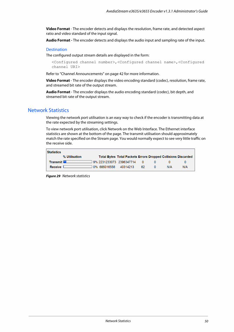
AvediaStream e3635/e3655 Encoder v1.3.1 Administrator’s Guide
Video Format - The encoder detects and displays the resolution, frame rate, and detected aspect ratio and video standard of the input signal.
Audio Format - The encoder detects and displays the audio input and sampling rate of the input.
DestinationThe configured output stream details are displayed in the form:
<Configured channel number>,<Configured channel name>,<Configured channel URI>
Refer to “Channel Announcements” on page 42 for more information.
Video Format - The encoder displays the video encoding standard (codec), resolution, frame rate, and streamed bit rate of the output stream.
Audio Format - The encoder displays the audio encoding standard (codec), bit depth, and streamed bit rate of the output stream.
Network StatisticsViewing the network port utilisation is an easy way to check if the encoder is transmitting data at the rate expected by the streaming settings.
To view network port utilisation, click Network on the Web Interface. The Ethernet interface statistics are shown at the bottom of the page. The transmit utilisation should approximately match the rate specified on the Stream page. You would normally expect to see very little traffic on the receive side.
Figure 29 Network statistics
Network Statistics 50

7 Maintenance
This chapter describes various maintenance tasks. It covers:
• Specifying the TFTP Server Address
• Specifying the SNMP Trap Manager IP Address
• Specifying the Time Server Address
• Restarting the Encoder
• Upgrading Firmware
• Restoring Factory Defaults
• Exporting/Importing Configuration Settings
• Logging
Maintenance tasks are managed from the Maintenance page which is shown in Figure 30.
Figure 30 Maintenance Page
Specifying the TFTP Server AddressThe encoder uses TFTP to download new firmware releases and configuration files. For this to operate correctly, it must be configured to communicate with the TFTP server.
To specify the TFTP server IP address:
1 Click Maintenance.
Specifying the TFTP Server Address 51

AvediaStream e3635/e3655 Encoder v1.3.1 Administrator’s Guide
2 Enter the IP address of the TFTP server in the TFTP Server field (default:194.168.0.28).
3 Click Apply.
Specifying the SNMP Trap Manager IP Address SNMP traps are mainly used as device discovery messages; they enable Exterity’s management applications to discover devices on the network. These traps are always broadcast on the local subnet. They are also transmitted to an additional configurable destination. By default, this is the multicast address 239.255.255.255, but this can be reconfigured to any broadcast, multicast or unicast destination as required.
To set the SNMP trap manager address:
1 Click Maintenance to display the page as shown in Figure 30.
2 Enter the required IP address in the SNMP Trap Manager field.
3 Click Apply.
Specifying the Time Server AddressUsing a time server with the Time Zone configuration ensures all devices in your IPTV system are synchronised to the current local time in use. The encoder uses NTP (Network Time Protocol) to maintain accurate time on the device, using the time server specified. This is useful when examining the device log file as each log message has an accurate universal time code (UTC) timestamp.
Figure 31 Network time server
Note: When DHCP is used and the DHCP server supplies an NTP server address, any NTP servers configured using the Web Interface are ignored. If the DHCP server does not supply an NTP server address, the address must be configured.
To specify a time server:
1 Click Maintenance.
2 Enter the IP address or the host name of the time server in the Time Server field. If already configured, the IP address is displayed.
3 Click Apply.
Restarting the EncoderYou can restart the encoder to return it to a known state. All current settings are maintained during a reboot. To restart the encoder at any time, click Maintenance and click Reboot Encoder.
Specifying the SNMP Trap Manager IP Address 52

AvediaStream e3635/e3655 Encoder v1.3.1 Administrator’s Guide
Upgrading FirmwareBy upgrading firmware regularly, you can ensure that you are always using the most recent version. As the new firmware is uploaded using TFTP, you must first ensure that the encoder is using the correct TFTP server address (see “Specifying the TFTP Server Address” on page 51).
Caution: Do not switch the encoder off while the upgrade process is running. The process requires several minutes, during which time the LED flashes indicating that the upgrade is in process, firstly by flashing on/off at half second intervals, then rapid flashing as the new firmware is copied to flash memory. When the LED returns to flashing once per second, the process is complete.
To upgrade the encoder to a new version of firmware:
1 Click Maintenance.
2 Ensure that you have specified the IP address of your TFTP server and that it is running and configured correctly.
3 Ensure that the following firmware file is hosted correctly in the root directory of the TFTP server:
xcoder_vx.bin
4 Ensure that the Firmware filename field shows the file indicated above (or matches the name of the firmware file if this is different).
5 Click Upgrade firmware.
6 The firmware is downloaded from the TFTP server and copied to flash, and the encoder restarted. This process will take several minutes.
Restoring Factory DefaultsYou can return the encoder to its factory default configuration.
Note: When resetting to factory default settings, all previously saved settings are lost. IP addressing is also returned to DHCP. You can however restore previous settings if you have saved your configuration, as described later in this section.
To restore the factory default settings:
1 Click Maintenance.
2 Click Return to factory defaults.
3 Click Return to factory defaults again to continue. The device reboots.
Exporting/Importing Configuration SettingsOnce you have set up the encoder, you can save its configuration settings in a single file. You can use the saved configuration file to restore the settings if required, or replicate identical settings on additional devices. The configuration files are exported and imported using the TFTP process.
Note: Device naming and IP addressing information is not exported/imported. This means that a configuration file can be imported to multiple units.
To export configuration settings:
1 Ensure that the TFTP server is running and is correctly configured (see “Specifying the TFTP Server Address” on page 51).
2 Click Maintenance.
3 Enter a name for your configuration archive in the Export filename field.
Upgrading Firmware 53

AvediaStream e3635/e3655 Encoder v1.3.1 Administrator’s Guide
4 Click Export configuration.
The configuration file is uploaded to the root directory of the TFTP server.
To import configuration settings:
1 Ensure that the TFTP server is running and that the configuration file is hosted in the root directory of the TFTP server.
2 Click Maintenance.
3 Enter the name of the configuration file in the Import Filename field.
4 Click Import Configuration to continue.
The configuration file is downloaded from the TFTP server and the encoder reboots.
LoggingThe encoder saves historical information about internal events within the device to its log file. This can be useful when troubleshooting problems with the device. All log file information is automatically saved locally and can be viewed in the Web Interface. It is also possible to send these log messages to a remote syslog server.
Use of a time server with the Time Zone configuration ensures all devices in your IPTV system are synchronised. The encoder uses NTP to maintain an accurate time on the device, useful when examining log files as each log message has an accurate timestamp (UTC time zone).
Logging is configured in the Web Interface Logging page as shown in Figure 32.
Figure 32 Logging Page
Local LoggingYou can view the log file in the Web Interface or download it to your computer.
To view the log file:
1 Click Logging.
2 Click Show Log to display the log in a browser window.
Logging 54

AvediaStream e3635/e3655 Encoder v1.3.1 Administrator’s Guide
Figure 33 Logging example
3 Click Hide Log to close the log display.
To download the log file:
1 Click Logging.
2 Click Download log to download the log file to the configured download folder on your local computer.
Note: Exterity recommends that you use Wordpad to view the downloaded log file.
Remote LoggingTo send device log information to a remote server, you need to install a syslog server application on the remote server. Then set up the remote logging function on the encoder as described below.
To configure remote logging:
1 Click Logging.
2 Select Local and Remote from the Logging drop-down list.
3 In the Syslog server field, enter the IP address or host name of the syslog server where the log files are to be stored.
4 In the Syslog port field, enter the port number on the syslog server. The default value is 514.
5 Click the Logging level drop-down list and select an option ranging from 0-Emergency to 7-Debug, where 0 represents the least debug information and 7 represents the most.
6 Click Apply.
Logging 55

8 Troubleshooting
Problem Possible Cause Solution
Device does not appear in AvediaServer Director.
Network connection faulty or cannot obtain IP address.
Check Ethernet connections or replace cable.
Check that DHCP Server is running on network.
Check switch settings match unit Ethernet settings.
AvediaServer Director cannot communicate with device.
Network connection faulty. See above
Device has an IP address on a different subnet from the management station.
Use a management station configured with an appropriate IP address to manage the device.
Device is upgrading (indicated by alternately slow and fast LED flash).
Wait for upgrade to complete.
SNMP is not enabled on the device. Check that SNMP is enabled. If not, turn it on.
Encoder does not appear to be streaming.
AV source not connected or powered off.
Check connections and power to AV source. Check the status page to see if the encoder thinks it is attached to a valid video source.
Video input setting wrong. Check the video input setting matches the AV input to the encoder.
Device is definitely streaming but client cannot connect to stream.
Multicast address is not unique. Particularly if the multicast address was assigned manually, check it is unique.
Client cannot accept encoding type. Update the client software or use a different client to view the stream.
If using PC client, PC firewall is preventing video traffic.
Disable firewall, or configure firewall to allow traffic to this application.
Device is streaming but video and or audio is broken up on client.
Network is not IGMP enabled. Check the configuration of the network switch(es).
Check the switch(es) for errors.
The streaming bit rate exceeds the capability of the client.
Lower the encoding bit rate.
After upgrade, the device is still running the old version of firmware.
The correct firmware file is not on the TFTP Server.
Put the correct file on the TFTP Server.
The TFTP Server address configured for the device is wrong
Check that the TFTP Server address is the address of the machine the TFTP Server is running on.
The TFTP Server is not running. Start the TFTP Server.
The TFTP Server is not configured to send files.
Fix the security settings on the TFTP Server.
Board temperature more than 20 degrees centigrade above ambient temperature.
Air vents are blocked. Check that air vents are not blocked.
Fans have stopped running. Check that fans are running.
None of the above. If the problem persists, switch off the unit and contact your Exterity systems integrator or reseller.
56

Exterity AvediaPlayer r92xx Series Receiver version 3.2
Section 4 Appendices
This section contains information on how to:
• Use the serial Admin Interface to manage a small subset of device functionality
• Get support for AvediaStream Encoders

A Serial Admin Interface Connection
The serial Admin Interface provides access to a small subset of device functionality. For example, you can configure an IP address using a terminal program session, such as PuTTY or HyperTerminal.
CablingTo connect to the serial interface use the female DB-9 to RJ45 adaptor shown in Figure 34 (Exterity part number access-srl), or the USB – RJ45 serial cable shown in Figure 35 (Exterity part number access-usb).
Figure 34 DB-9 – RJ45 serial adaptor
Figure 35 USB – RJ45 serial cable
The female DB-9 connector should be plugged into the serial port on a PC. A straight-through network cable should be used between the RJ45 socket on the adaptor and the admin port on the Exterity device.
Note that although the cable fits, the admin port should not be connected to the Ethernet port on a PC.
Adaptor WiringIf you do not have an adaptor you can make one using the details shown in Figure 36.
Figure 36 DB-9 to RJ45 connector
Cabling 58

AvediaStream e3635/e3655 Encoder v1.3.1 Administrator’s Guide
Opening a Session1 Open a terminal program such as PuTTY or HyperTerminal.
2 Set up the serial port with the following settings:
• Baud rate: 115200
• Data bits: 8
• Parity: none
• Stop bits: 1
• Flow control: none
The program should now connect and present a login prompt if the return key is pressed.
Figure 37 Serial port settings
Table 6 Serial Pin Out
DB9 Connector Pin No Description RJ45 Pin No
2 TxD 8
3 RxD 2
5 GND 4
Opening a Session 59

B Support and Contact Information
Technical Support for Exterity products is provided by authorised Systems Integrators and Resellers. Please contact your Systems Integrator or Reseller with any support issues.
60