Embed Size (px)
Citation preview
Extending Team Software Process (TSP)
to Systems Engineering: A NAVAIR
Experience Report
Anita Carleton Jim Over
Jeff Schwalb
Delwyn Kellogg
Timothy A. Chick
March 2010
TECHNICAL REPORT CMU/SEI-2010-TR-008 ESC-TR-2010-008
Software Engineering Process Management Program Unlimited distribution subject to the copyright.
http://www.sei.cmu.edu
This report was prepared for the
SEI Administrative Agent
ESC/XPK
5 Eglin Street
Hanscom AFB, MA 01731-2100
The ideas and findings in this report should not be construed as an official DoD position. It is published in the
interest of scientific and technical information exchange.
This work is sponsored by the U.S. Department of Defense. The Software Engineering Institute is a federally
funded research and development center sponsored by the U.S. Department of Defense.
Copyright 2010 Carnegie Mellon University.
NO WARRANTY
THIS CARNEGIE MELLON UNIVERSITY AND SOFTWARE ENGINEERING INSTITUTE MATERIAL IS
FURNISHED ON AN “AS-IS” BASIS. CARNEGIE MELLON UNIVERSITY MAKES NO WARRANTIES OF
ANY KIND, EITHER EXPRESSED OR IMPLIED, AS TO ANY MATTER INCLUDING, BUT NOT LIMITED
TO, WARRANTY OF FITNESS FOR PURPOSE OR MERCHANTABILITY, EXCLUSIVITY, OR RESULTS
OBTAINED FROM USE OF THE MATERIAL. CARNEGIE MELLON UNIVERSITY DOES NOT MAKE
ANY WARRANTY OF ANY KIND WITH RESPECT TO FREEDOM FROM PATENT, TRADEMARK, OR
COPYRIGHT INFRINGEMENT.
Use of any trademarks in this report is not intended in any way to infringe on the rights of the trademark holder.
Internal use. Permission to reproduce this document and to prepare derivative works from this document for
internal use is granted, provided the copyright and “No Warranty” statements are included with all reproductions
and derivative works.
External use. This document may be reproduced in its entirety, without modification, and freely distributed in
written or electronic form without requesting formal permission. Permission is required for any other external
and/or commercial use. Requests for permission should be directed to the Software Engineering Institute at
This work was created in the performance of Federal Government Contract Number FA8721-05-C-0003 with
Carnegie Mellon University for the operation of the Software Engineering Institute, a federally funded research
and development center. The Government of the United States has a royalty-free government-purpose license to
use, duplicate, or disclose the work, in whole or in part and in any manner, and to have or permit others to do so,
for government purposes pursuant to the copyright license under the clause at 252.227-7013
.
i | CMU/SEI-2010-TR-008
Table of Contents
Acknowledgments vii
Executive Summary ix
Abstract xiii
1 Introduction, Background, and Objectives 1
1.1 Introduction 1
1.2 Background 2
1.3 Objectives & Goals 3
2 Roadmap for Pilot Project 5
2.1 Concept Exploration 6
2.1.1 Schedule Performance 7
2.1.2 Cost Performance 8
2.1.3 Feature Performance 8
2.1.4 Responsiveness 8
2.1.5 Predictability 9
2.1.6 Quality-of-Life 9
2.1.7 Quality Performance 10
2.1.8 Customer Satisfaction 10
2.2 AV-8B System Engineering Before and After TSPI 11
2.2.1 Definition of Terms 11
2.2.2 Before and After Using TSPI 11
2.3 Conduct Research 15
2.4 Pilot 16
2.4.1 TSPI Introduction Strategy 16
2.4.2 Pilot Project Phases 17
2.4.3 Initial AV-8B System Engineering Pilot Project Observations 18
3 Guiding Principles 21
4 Research Challenges 25
5 AV-8B Project Progress and Performance 31
6 Lesson Learned 35
7 Summary/Conclusions 37
8 Next Steps 41
9 Appendix A: Questionnaire for Interviewing DoD Program Managers for TSPI Acquisition Pilot Project 43
Appendix B: TSPI Measures 47
Appendix C: TSPI Acquisition Process and Scripts 55
Appendix D: Systems Engineering Processes and Scripts 67
Bibliography 87

ii | CMU/SEI-2010-TR-008
iii | CMU/SEI-2010-TR-008
List of Figures
Figure 1: Capabilities Provided by Software in DoD Systems are Increasing, But So Are the Challenges 1
Figure 2: NAVAIR China Lake and Patuxent River Divisions to Demonstrate TSPI Feasibility 4
Figure 3: Roadmap for NAVAIR/SEI TSPI Collaboration 6
Figure 4: The Acquisition Process 26
Figure 5: Percentage of Tasks Completed Within Percentage of Planned Time 31
Figure 6: Task Hours by Work Component 32

iv | CMU/SEI-2010-TR-008
v | CMU/SEI-2010-TR-008
List of Tables
Table 1: TSP Results at NAVAIR 2
Table 2: “Before/After TSPI” Picture of AV8B Systems Engineering Pilot Project Team 11
Table 3: Relative Size of TWDs 32

vi | CMU/SEI-2010-TR-008
vii | CMU/SEI-2010-TR-008
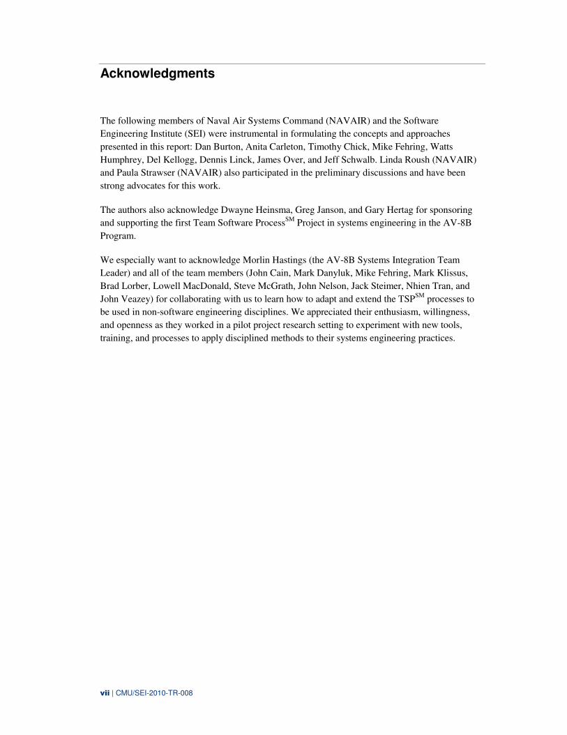
Acknowledgments
The following members of Naval Air Systems Command (NAVAIR) and the Software
Engineering Institute (SEI) were instrumental in formulating the concepts and approaches
presented in this report: Dan Burton, Anita Carleton, Timothy Chick, Mike Fehring, Watts
Humphrey, Del Kellogg, Dennis Linck, James Over, and Jeff Schwalb. Linda Roush (NAVAIR)
and Paula Strawser (NAVAIR) also participated in the preliminary discussions and have been
strong advocates for this work.
The authors also acknowledge Dwayne Heinsma, Greg Janson, and Gary Hertag for sponsoring
and supporting the first Team Software ProcessSM
Project in systems engineering in the AV-8B
Program.
We especially want to acknowledge Morlin Hastings (the AV-8B Systems Integration Team
Leader) and all of the team members (John Cain, Mark Danyluk, Mike Fehring, Mark Klissus,
Brad Lorber, Lowell MacDonald, Steve McGrath, John Nelson, Jack Steimer, Nhien Tran, and
John Veazey) for collaborating with us to learn how to adapt and extend the TSPSM
processes to
be used in non-software engineering disciplines. We appreciated their enthusiasm, willingness,
and openness as they worked in a pilot project research setting to experiment with new tools,
training, and processes to apply disciplined methods to their systems engineering practices.

viii | CMU/SEI-2010-TR-008
ix | CMU/SEI-2010-TR-008
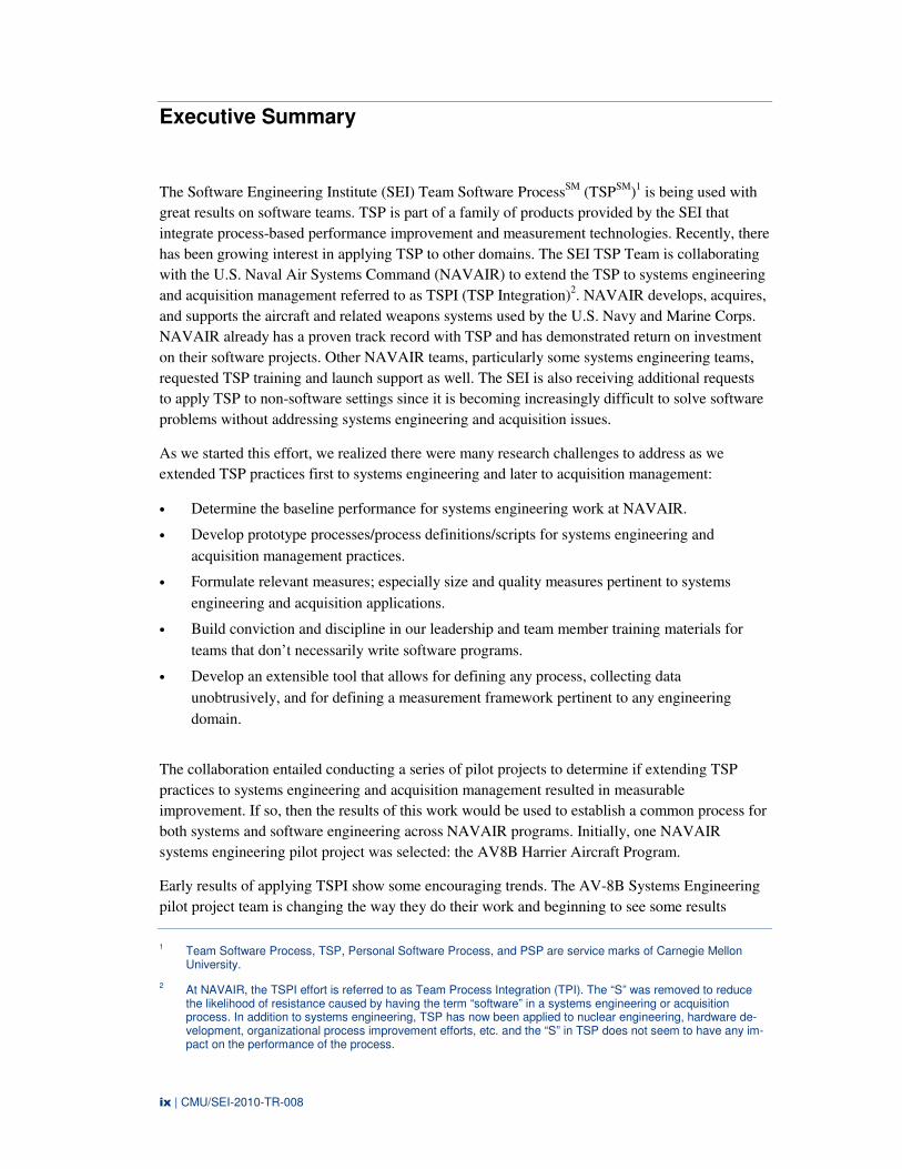
Executive Summary
The Software Engineering Institute (SEI) Team Software ProcessSM
(TSPSM
)1 is being used with
great results on software teams. TSP is part of a family of products provided by the SEI that
integrate process-based performance improvement and measurement technologies. Recently, there
has been growing interest in applying TSP to other domains. The SEI TSP Team is collaborating
with the U.S. Naval Air Systems Command (NAVAIR) to extend the TSP to systems engineering
and acquisition management referred to as TSPI (TSP Integration)2. NAVAIR develops, acquires,
and supports the aircraft and related weapons systems used by the U.S. Navy and Marine Corps.
NAVAIR already has a proven track record with TSP and has demonstrated return on investment
on their software projects. Other NAVAIR teams, particularly some systems engineering teams,
requested TSP training and launch support as well. The SEI is also receiving additional requests
to apply TSP to non-software settings since it is becoming increasingly difficult to solve software
problems without addressing systems engineering and acquisition issues.
As we started this effort, we realized there were many research challenges to address as we
extended TSP practices first to systems engineering and later to acquisition management:
• Determine the baseline performance for systems engineering work at NAVAIR.
• Develop prototype processes/process definitions/scripts for systems engineering and
acquisition management practices.
• Formulate relevant measures; especially size and quality measures pertinent to systems
engineering and acquisition applications.
• Build conviction and discipline in our leadership and team member training materials for
teams that don’t necessarily write software programs.
• Develop an extensible tool that allows for defining any process, collecting data
unobtrusively, and for defining a measurement framework pertinent to any engineering
domain.
The collaboration entailed conducting a series of pilot projects to determine if extending TSP
practices to systems engineering and acquisition management resulted in measurable
improvement. If so, then the results of this work would be used to establish a common process for
both systems and software engineering across NAVAIR programs. Initially, one NAVAIR
systems engineering pilot project was selected: the AV8B Harrier Aircraft Program.
Early results of applying TSPI show some encouraging trends. The AV-8B Systems Engineering
pilot project team is changing the way they do their work and beginning to see some results
1 Team Software Process, TSP, Personal Software Process, and PSP are service marks of Carnegie Mellon
University.
2 At NAVAIR, the TSPI effort is referred to as Team Process Integration (TPI). The “S” was removed to reduce the likelihood of resistance caused by having the term “software” in a systems engineering or acquisition process. In addition to systems engineering, TSP has now been applied to nuclear engineering, hardware de-velopment, organizational process improvement efforts, etc. and the “S” in TSP does not seem to have any im-pact on the performance of the process.
x | CMU/SEI-2010-TR-008
similar to those realized by TSP teams. The team is practicing more disciplined methods for
planning and executing their work, meeting their missions, and they are beginning to see some
cost savings. In addition, the pilot team is inspiring other NAVAIR 4.0 System Support activities
(SSAs) to pursue process improvement activities.
Through the pilot effort, we saw the following benefits:
1. Establishing a Systems Engineering Baseline. Through the AV-8B Systems Engineering
Pilot Project, we are beginning to establish a baseline for systems engineering performance
at NAVAIR that can be used for estimating, planning, and tracking projects/programs.
− The Requirements Productivity Rate varies between 3 and 9 DOORS Objects per hour
depending on the complexity of the project.
− By just tracking size growth, the team was able to decrease the rate of size growth from
23.6% in cycle 1 to 11.54% in cycle 2.
− Requirement size measures were baselined for three components.
− The team leader commented: “Prior to TSPI, we made estimates in a bubble. Now we
are establishing and maintaining baselines for all of our releases, which allows us to
make better estimates and more realistic plans and schedules.”
2. Establishing Planning Practices. Planning at the program and team level is now
accomplished by holding three AV-8B multi-team launches a year. This process is used by
the AV-8B program to understand requirements from management, assemble plans, allocate
work, and achieve commitment to plans from management and team members. The overall
plan for the year and the next-phase plan are developed by the teams, work is allocated by
the team, and the schedule is determined and committed to by team members.
3. Establishing Tracking Practices. For tracking purposes, work is broken down into small
chunks that can easily be tracked (tasks are tracked at a granularity of less than 10 hours).
Work is tracked daily by team members and discussed weekly in team meetings—every
team member knows how they are performing to their individual plan and the team plan
weekly. Monthly status reports are derived from the consolidated weekly reports by the team
leader and presented to the IPT Leads.
− Twelve team members were able to achieve (on average) 18-22 on-project task hours per
week. The team performed well above the planned task hours of 15 task hours per week
in the first cycle.
− Engineers embraced project planning and tracking. Each individual was able to track
personal commitments to the team, which enabled the team to better track commitments
to the program. Tracking the work is helping team members to stay on track. One team
member said, “I need to stop doing X to get back on track. It is very easy to see the
impact daily and weekly of not working to the plan.”
4. Standard Processes, Measures, and Tools. Standard processes, measures, terminology, and
tools were developed and used by the AV-8B Program.
− The Excel Spreadsheet and PST (Process Support Technology) Access-based Tool were
used for estimating, planning, and tracking work for team members and team leads.
xi | CMU/SEI-2010-TR-008
− Team members identified, defined, and documented all systems engineering standard
lifecycle processes in the tool. The team defined and developed the following:
− an 18 step overall systems engineering process
− a 482 step detailed systems engineering process
Through the defined processes, NAVAIR was able to maintain consistency of processes
across projects and programs. The defined processes also offered the ability to cross-train
individuals. One comment collected was: “We have a team concept across our program with
all of the sub-teams (systems engineering, product integrity, software, test, lab, etc…). We
also have a common set of processes and metrics to help all of the teams better communicate
and address dependencies across the teams.”
5. Schedule, Cost, and Quality Performance Trends. The following performance trends were
identified:
− Schedule performance: The team established a goal of less than 5% schedule slip and
measured performance against the goals. The actual performance was less than 10%
overrun.
− Cost performance: Size and effort estimates were within 10% of what was planned.
− Quality performance: There were no priority 1 or 2 problem reports coming out of test.
6. Employee Work Life Balance. TSPI helped improve employee work/life balance. Overtime
was decreased from being standard practice—sometimes 25% or more—to “occasional”
overtime hours (less than 10%).
7. Customer Responsiveness. Customer responsiveness has improved to the fleet, the naval
aviators, and to the internal program managers. The systems engineering team is now a more
agile team that can more easily adapt to program and personnel changes. The pilots are
beginning to provide input early in the project, during the launch process, and before the
work has commenced instead of providing feedback during the test phases. Program
management feels that the TSP and TSPI efforts are a success because the teams understand
their work and the dependencies among all of the teams. The team can also plan for a
percentage of unplanned tasks and uses their data to negotiate impact and trade-offs of
unplanned work to planned work.
To build integrated teams and quality systems from requirements to field deployment, we must
establish the right foundation. This task consists of estimation and planning processes, team
processes, development and management practices, effective and timely training, launching,
coaching, and operational support. This report shows the great improvements possible when
teams use TSPI to establish this foundation to meet critical business needs by delivering high
quality systems on schedule and with improved productivity.

xii | CMU/SEI-2010-TR-008
xiii | CMU/SEI-2010-TR-008
Abstract
The purpose of this report is to communicate status, progress, lessons learned, and results on a
joint collaboration between the Software Engineering Institute (SEI) and Naval Air Systems
Command (NAVAIR). The collaboration is referred to as Team Software Process Integration
(TSPI). This report describes the progress and performance of extending the Team Software
Process (TSP) to systems engineering as a pilot project with the AV8B Systems Engineering
Team. Early results of applying TSPI suggest some encouraging trends. The motivation for
assembling this report is to share lessons and experiences with other industry and government
organizations interested in applying TSP in a non-software setting.
The TSPI effort leverages the SEI Personal Software ProcessSM
(PSPSM
) and Team Software
ProcessSM
(TSPSM
) research and body of practice. Projects that have adopted these methods have
shown a dramatic increase in product quality as well as increased fidelity to their schedule and
effort estimates. The methods are supported by a doctrine that trains and sustains performance and
quality improvement in organizations.

xiv | CMU/SEI-2010-TR-008
1 | CMU/SEI-2010-TR-008
1 Introduction, Background, and Objectives
1.1 INTRODUCTION
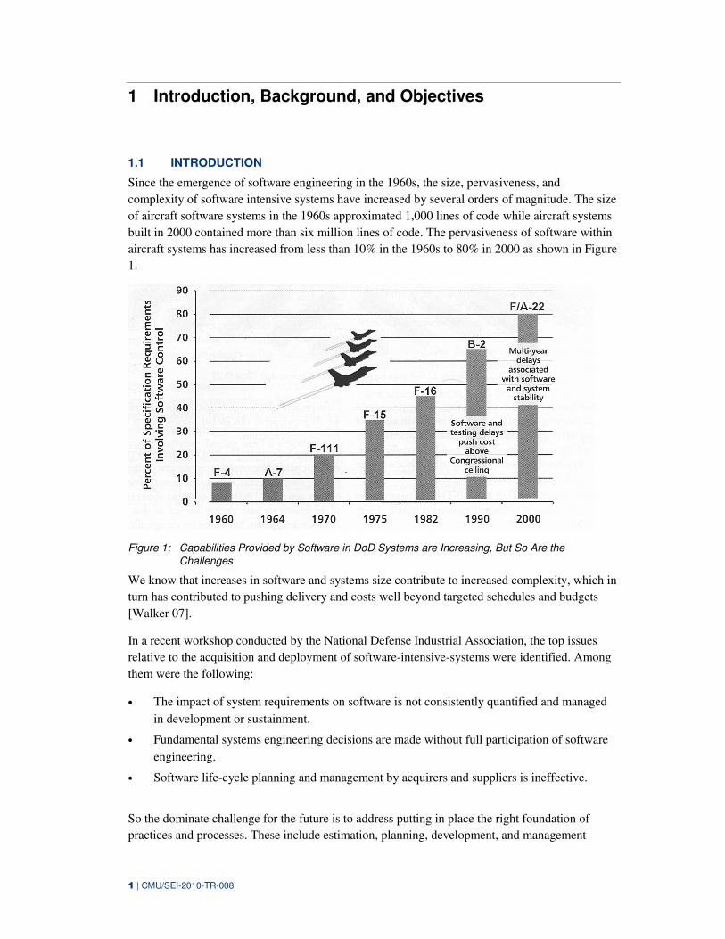
Since the emergence of software engineering in the 1960s, the size, pervasiveness, and
complexity of software intensive systems have increased by several orders of magnitude. The size
of aircraft software systems in the 1960s approximated 1,000 lines of code while aircraft systems
built in 2000 contained more than six million lines of code. The pervasiveness of software within
aircraft systems has increased from less than 10% in the 1960s to 80% in 2000 as shown in Figure
1.
Figure 1: Capabilities Provided by Software in DoD Systems are Increasing, But So Are the
Challenges
We know that increases in software and systems size contribute to increased complexity, which in
turn has contributed to pushing delivery and costs well beyond targeted schedules and budgets
[Walker 07].
In a recent workshop conducted by the National Defense Industrial Association, the top issues
relative to the acquisition and deployment of software-intensive-systems were identified. Among
them were the following:
• The impact of system requirements on software is not consistently quantified and managed
in development or sustainment.
• Fundamental systems engineering decisions are made without full participation of software
engineering.
• Software life-cycle planning and management by acquirers and suppliers is ineffective.
So the dominate challenge for the future is to address putting in place the right foundation of
practices and processes. These include estimation, planning, development, and management
2 | CMU/SEI-2010-TR-008
practices as well as team processes, training, coaching, and operational support that will support a
migration from “buggy” products and unnecessary rework resulting in inflating development costs
to a proactive approach that builds integrated, quality software-intensive systems from
requirements to field deployment.
1.2 BACKGROUND
TSP provides engineers with a structured framework for doing software engineering work. It
includes scripts, forms, measures, standards, and tools that show software engineers how to use
disciplined processes to plan, measure, and manage their work [Humprey 06]. The principal
motivator for TSP is the conviction that engineering teams can do extraordinary work if such
teams are properly formed, suitably trained, staffed with skilled members, and effectively coached
and led.
The TSP is already being used with great results on software teams [Davis 03]. A Microsoft study
reported that by using TSP, teams cut schedule error from 10% to 1%. With its TSP teams, Intuit
has increased the time that teams can spend in developing a product during a typical year-long
release cycle by almost 50% because increased quality has dramatically cut testing time required.
An analysis of 20 projects in 13 organizations showed TSP teams averaged 0.06 defects per
thousand lines of new or modified code. Approximately 1/3 of these projects were defect-free.
Other studies show that TSP teams delivered their products an average of 6% later than they had
planned. This compares favorably with industry data which shows over half of all software
projects were more than 100% late or were cancelled. These TSP teams also improved their
productivity by an average of 78%.
Recently, there is growing interest in applying TSP to other domains. The SEI TSP Team is
collaborating with the U.S. Naval Air Systems Command (NAVAIR) to extend the Team
Software Process (TSP) to systems engineering and acquisition management. NAVAIR develops,
acquires, and supports the aircraft and related weapons systems used by the U.S. Navy and
Marine Corps. NAVAIR already has a proven track record with TSP and has demonstrated return
on investment on their software projects [Wall 05]. Table 1 shows some TSP results from two
NAVAIR programs: the AV-8B's Joint Mission Planning System (AV JMPS) program and the P-
3C program. The return on investment of applying and using TSP was $3,225,606. This
represents the gross savings ($3,782,153) minus the investment in TSP ($556,547).
Table 1: TSP Results at NAVAIR
Program Size of Program Defect Density(Defects/KSLOC) Cost Savings from Reduced Defects
AV JMPS 443 KSLOC 0.59 $2,177,169
P-3C 383 KSLOC 0.6 $1,478,243
Both organizations have standardized on TSP for all projects and have ongoing returns from
initial investment. These early adopters are meeting their missions, producing higher quality
products, and generating significant cost savings. These programs inspired other NAVAIR
System Support Activities (SSAs) to use TSP. There are 21 additional NAVAIR SSAs now
pursuing software process improvement activities. NAVAIR is seeing recurring savings and can
now direct cost savings to the procurement of additional aircraft and weapons. In addition,
3 | CMU/SEI-2010-TR-008
NAVAIR used TSP to accelerate CMMI improvement. Their TSP groups reached maturity level 4
in 28 months instead of the typical six years [Wall 05]. Development teams like using TSP. A
typical comment heard is that “Once they have adopted TSP, they can’t imagine working any
other way.”
Based on the demonstrated, measured success of software projects using TSP in NAVAIR, other
teams asked if they could apply the same processes to systems engineering and software and
systems acquisition projects. As a result, NAVAIR has teamed with the SEI to expand the TSP
framework to a technology named Team Software Process Integration (TSPI)3. The SEI is also
receiving additional requests to apply TSP to non-software settings since it is becoming
increasingly difficult to solve software problems without addressing systems engineering and
acquisition issues.
The NAVAIR/SEI collaboration entails testing the hypothesis that we can achieve the same kind
of performance improvements applying TSPI to systems engineering as we did applying TSP to
software projects thereby improving management and communication in software-intensive
systems and software-intensive systems acquisitions.4 The NAVAIR/SEI approach will entail
conducting a series of pilot projects to determine if extending TSP practices to systems
engineering and acquisition management results in measurable improvement. Then we will use
the results of this work to establish common processes for both systems and software engineering
across NAVAIR. Initially, the AV-8B Harrier Aircraft Program was selected as the systems
engineering pilot.
1.3 OBJECTIVES & GOALS
TSPI is aimed at extending TSP practices to other non-software engineering domains. The near-
term goal is to conduct pilot projects to determine if extending TSP practices to systems
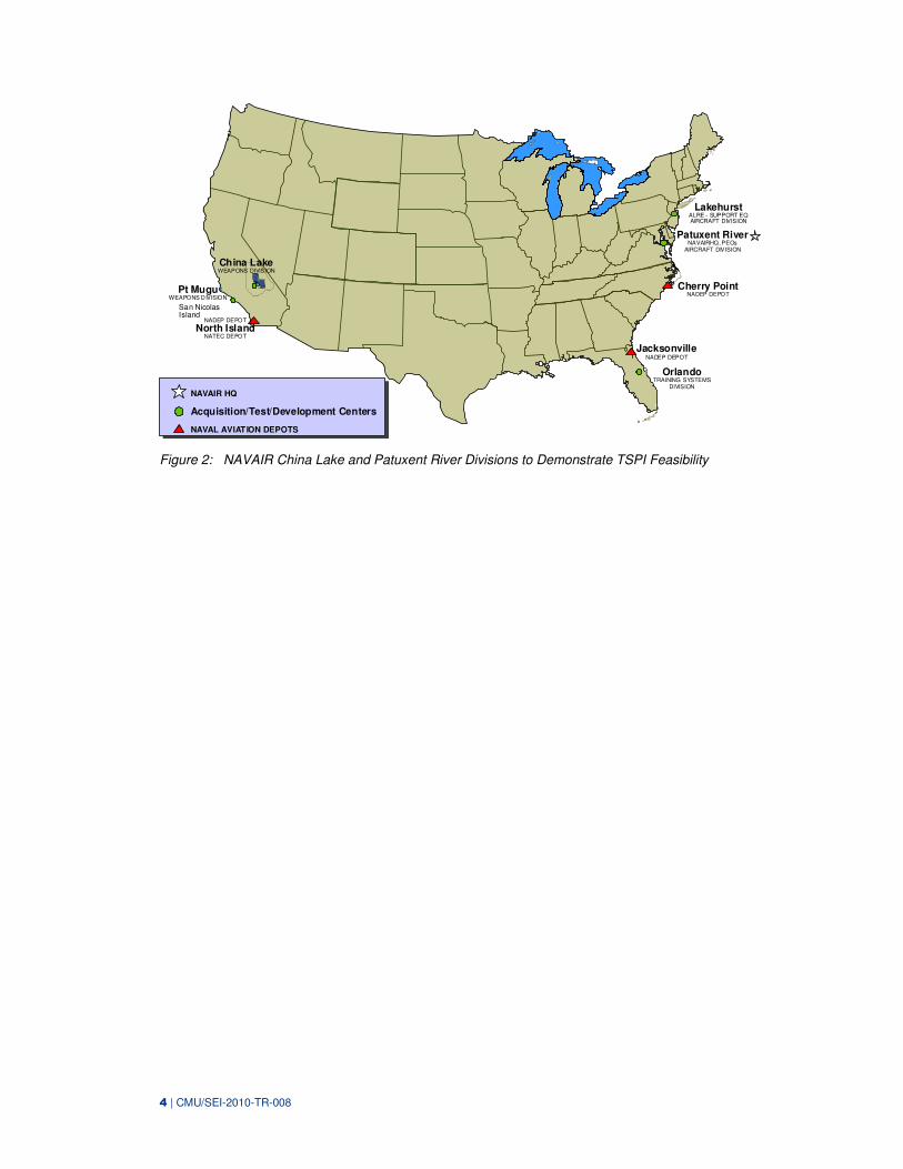
engineering and acquisition management results in measurable improvement. The goal of TSPI is
to demonstrate feasibility with NAVAIR pilot projects on the West Coast (Weapons Division in
China Lake, California) and East Coast (Aircraft Division in Patuxent River, Maryland) (Figure
2). We want to demonstrate that distributed teams using tailorable process scripts, metrics, and
automated tool support can deliver high quality products and services on cost and schedule.
3 At NAVAIR, this effort is referred to as Team Process Integration (TPI). The “S” was removed to reduce the
likelihood of resistance caused by having the term “software” in a systems engineering or acquisition process. In addition to systems engineering, TSP has now been applied to nuclear engineering, hardware development, organizational process improvement efforts, etc. and the “S” in TSP does not seem to have any impact on the performance of the process.
4 The Department of Defense defines a software-intensive system as one in which a significant portion or com-ponent of the functionality is implemented in software or where software presents the primary technical or pro-grammatic challenge to the system developer. One policy instruction issued by the Naval Air Systems Com-mand defines software-intensive systems as those with more than 10,000 source lines of code [NAVAIR 02]
4 | CMU/SEI-2010-TR-008
NADEP DEPOT
North IslandNATEC DEPOT
Pt MuguWEAPONS DIVISION
NAVAIR HQ
Acquisition/Test/Development Centers
NAVAL AVIATION DEPOTS
JacksonvilleNADEP DEPOT
OrlandoTRAINING SYSTEMS
DIVISION
LakehurstALRE - SUPPORT EQAIRCRAFT DIVISION
Patuxent River NAVAIRHQ, PEOs
AIRCRAFT DIVISION
Cherry Point NADEP DEPOT
China LakeWEAPONS DIVISION
San Nicolas Island
Figure 2: NAVAIR China Lake and Patuxent River Divisions to Demonstrate TSPI Feasibility
5 | CMU/SEI-2010-TR-008
2 Roadmap for Pilot Project
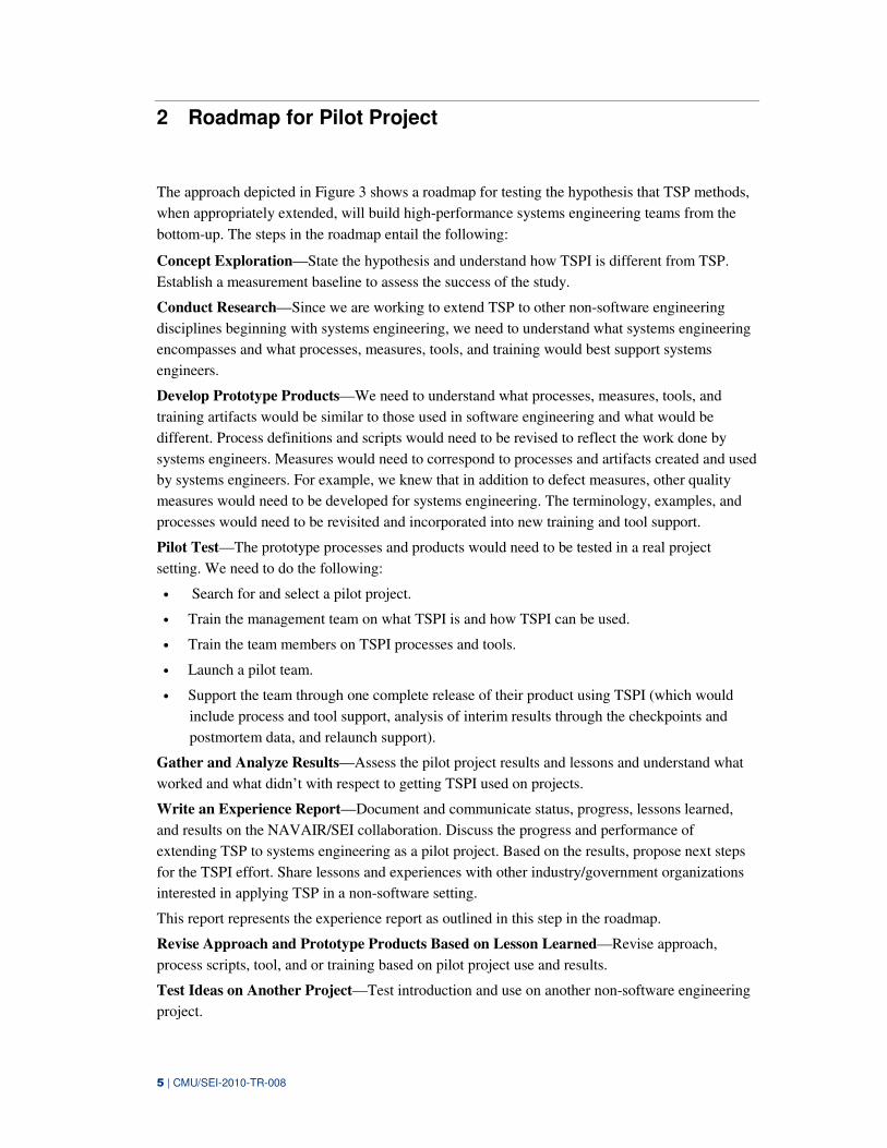
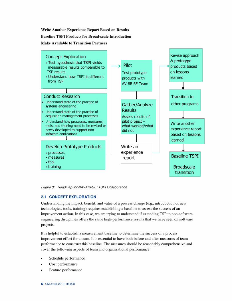
The approach depicted in Figure 3 shows a roadmap for testing the hypothesis that TSP methods,
when appropriately extended, will build high-performance systems engineering teams from the
bottom-up. The steps in the roadmap entail the following:
Concept Exploration—State the hypothesis and understand how TSPI is different from TSP.
Establish a measurement baseline to assess the success of the study.
Conduct Research—Since we are working to extend TSP to other non-software engineering
disciplines beginning with systems engineering, we need to understand what systems engineering
encompasses and what processes, measures, tools, and training would best support systems
engineers.
Develop Prototype Products—We need to understand what processes, measures, tools, and
training artifacts would be similar to those used in software engineering and what would be
different. Process definitions and scripts would need to be revised to reflect the work done by
systems engineers. Measures would need to correspond to processes and artifacts created and used
by systems engineers. For example, we knew that in addition to defect measures, other quality
measures would need to be developed for systems engineering. The terminology, examples, and
processes would need to be revisited and incorporated into new training and tool support.
Pilot Test—The prototype processes and products would need to be tested in a real project
setting. We need to do the following:
• Search for and select a pilot project.
• Train the management team on what TSPI is and how TSPI can be used.
• Train the team members on TSPI processes and tools.
• Launch a pilot team.
• Support the team through one complete release of their product using TSPI (which would
include process and tool support, analysis of interim results through the checkpoints and
postmortem data, and relaunch support).
Gather and Analyze Results—Assess the pilot project results and lessons and understand what
worked and what didn’t with respect to getting TSPI used on projects.
Write an Experience Report—Document and communicate status, progress, lessons learned,
and results on the NAVAIR/SEI collaboration. Discuss the progress and performance of
extending TSP to systems engineering as a pilot project. Based on the results, propose next steps
for the TSPI effort. Share lessons and experiences with other industry/government organizations
interested in applying TSP in a non-software setting.
This report represents the experience report as outlined in this step in the roadmap.
Revise Approach and Prototype Products Based on Lesson Learned—Revise approach,
process scripts, tool, and or training based on pilot project use and results.
Test Ideas on Another Project—Test introduction and use on another non-software engineering
project.
6 | CMU/SEI-2010-TR-008
Write Another Experience Report Based on Results
Baseline TSPI Products for Broad-scale Introduction
Make Available to Transition Partners
Figure 3: Roadmap for NAVAIR/SEI TSPI Collaboration
2.1 CONCEPT EXPLORATION
Understanding the impact, benefit, and value of a process change (e.g., introduction of new
technologies, tools, training) requires establishing a baseline to assess the success of an
improvement action. In this case, we are trying to understand if extending TSP to non-software
engineering disciplines offers the same high-performance results that we have seen on software
projects.
It is helpful to establish a measurement baseline to determine the success of a process
improvement effort for a team. It is essential to have both before and after measures of team
performance to construct this baseline. The measures should be reasonably comprehensive and
cover the following aspects of team and organizational performance:
• Schedule performance
• Cost performance
• Feature performance
Concept Exploration
•measurable results comparable to TSP results
•from TSP
Conduct Research
• Understand state of the practice of
systems engineering
• Understand state of the practice of acquisition management processes
• Understand how processes, measures, tools, and training need to be revised or
newly developed to support non-
software applications
Develop Prototype Products
• Processes
• Measures
• Tool
• Training
Pilot
• Test prototype products with
AV-8B SE Team
Gather/AnalyzeResults
• Assess results of pilot project – what worked/
’t?
WriteExperienceReport
Revise
Prototype
Products
Based on
Lessons Learned
Transition to
other programs
Write AnotherExperience
Report Based onLessons Learned
Broad-scale
Transition
Concept Exploration
• Test hypothesis that TSPI yields measurable results comparable to TSP results
• Understand how TSPI is different from TSP
Develop Prototype Products
• processes
• measures
• tool
• training
Pilot
Test prototype
products with
AV-8B SE Team
Gather/Analyze Results
Assess results of
pilot project – what worked/what
did not
Write an experience report
Write another
experience report
based on lessons
learned
Baseline TSPI
Broadscale
transition
Revise approach
& prototype
products based
on lessons
learned
7 | CMU/SEI-2010-TR-008
• Responsiveness
• Predictability
• Quality-of-life
• Quality performance
• Customer satisfaction
While these items may not be in the most appropriate order from a process-improvement
perspective, they are in the typical priority order for most current development organizations. The
reason is that, until organizations have their schedule and cost problems under control, they will
not be able to put quality higher on their priority scale. Once they do, quality will likely move
nearer to the top. Also, responsiveness, predictability, and quality-of-life are beginning to be
recognized as important contributors to schedule and cost performance.
Many of these measures could be relatively obvious when applied to entire projects with final
deliverables. However, for TSPI teams, it may be difficult to separate acquisition, systems
engineering, and development performance on schedule, cost, and quality. One way to separate
the work of these groups would be to define intermediate milestone deliverables. In the following
sections, these intermediate deliverables are indicated where appropriate.
Establishing some type of historical baseline on a project may initially require collecting whatever
data is readily available such as project size, cost, resource, schedule, quality data, and the like.
The following sections discuss possible measures for each of these categories before and after a
project.
2.1.1 Schedule Performance
Schedule performance should be simple to measure but rarely is. The problem concerns
requirements changes. However, if we consider requirements changes under the responsiveness
category, then the before and after schedule measures could be the following:
• The originally-planned project duration in weeks and days
• The actually-achieved project duration in weeks and days
Where the requirements and delivery dates changed during a project, the benchmarks should be
reset to count time from when the revised requirements and schedules were established and
committed.
For TSPI teams, the possible intermediate project milestones might be requirements documents,
the system-test suite, and the acceptance-test suite. All of these deliverables should be assumed to
be ready for development or other independent review or inspection and thus their quality and
completeness would be verifiable. However, a likely problem with this intermediate deliverable is
that they are rarely completed in a single step. Then, one might count the initial delivery, the final
delivery, or some weighted combination.
Probably a weighted measure would be most useful where, for example, a plan with 50% of the
requirements delivered in 10 weeks and 50% in 20 weeks would give a composite date of 15
weeks. Then, if 30% were actually delivered in 10 weeks (3), 40% in 15 weeks (6), and 30% in 25
8 | CMU/SEI-2010-TR-008
weeks (7.5), the weighted actual delivery date would be 3+6+7.5 = 16.5 or 10% and 1.5 weeks
late.
After data are obtained on several projects, it should also be possible to make more sophisticated
analyses of schedule performance. With the data collected, calculate the schedule performance of
a set of teams or even an entire organization in terms of average days late, average percent of days
late, percent of projects that were within some defined range of the commitment, the standard
deviation of schedule performance, and so forth.
With such data on prior-project performance, we could compare TSPI-project schedule
performance with a percentile scale of the organization’s prior performance.
These schedule measures could probably be the same for TSPI and prior teams.
2.1.2 Cost Performance
For cost performance, the suggested approach is essentially the same:
• The originally-planned project cost
• The actually-achieved project cost
The same adjustments should also be made: when the committed project schedule is changed, the
cost commitments should also be reset.
Intermediate cost milestones may be simple or impossible, depending on the organization’s
accounting practices. Initially, it would probably be best to stick with one simple overall cost
measure for TSPI teams.
The derived cost-analysis measures should be similar to those described for schedule, and the
measures would be the same for the TSPI and prior teams.
2.1.3 Feature Performance
While it is important to meet the objectives of “on time” and “on budget,” an equally important
consideration is system functionality. Cost and schedule objectives are not fully met if
functionality is reduced to achieve them. Therefore, it would be useful to document and track the
ratio of planned features to actual features implemented on a system as many organizations use
this as a basis for competition. For feature performance, the suggested approach would be to track
the following:
• The number of planned features
• The number of actual features
2.1.4 Responsiveness
A responsive organization would respond to a high rate of requested change without missing
delivery commitments. However, this does not mean that the original delivery commitments must
hold. Responsiveness does not mean doing additional work with no additional time or cost
penalty. It means responsively and accurately adjusting the plan to meet changing needs.
9 | CMU/SEI-2010-TR-008
One potential way to measure this would be to use a composite figure that is derived from the
requirements rate of change and the cost and schedule performance. A high rate of change with a
high cost and schedule rating would be very responsive while a high rate of change with a low
cost and schedule rating would be very poor. While this might not seem very useful, what it
means is that rating organizations on responsiveness is meaningless if cost and schedule
performance is poor. Therefore, a responsiveness measure is only useful for comparing
organizations with high cost and schedule performance ratings.
Again, the responsiveness measure would appear to be the same for both TSPI and prior teams.
2.1.5 Predictability
Predictability measures would be made during the project. The project would predict the final
delivery date at various points during the project, preferably every week or month. For example, if
a project estimated that it has 20 weeks to go when it actually had 22, which would be a 10%
error. However, if it had predicted 10 weeks and took 12, that would be a 20% error.
To get an overall project score, multiple intermediate estimates would be combined with some
averaging or weighting method. Since a simple average would give the same weight to early
predictions as to late predictions, some weighting system would probably be best. This weighting
should both recognize the difficulty of early estimating as well as the frequency and consistency
of these estimates. Initially, however, it would probably be best to start with a simple average and
to try more sophisticated ideas after seeing some actual data.
With a family of projections from several projects, it would be useful to examine and compare the
profiles, range, and variance. There should be some way to create a predictability measure from
such profiles which provides true insight, given sufficient data points.
While it is desirable to have historical measures of this type for non-TSPI teams, that would
almost certainly not be possible. However, it might be possible to start gathering these data in
parallel with the TSPI teams. The same measure would also probably work for both the TSPI and
prior teams.
2.1.6 Quality-of-Life
For quality-of-life (QOL) measures, there are two approaches: opinion surveys and indicators.
With opinion surveys, four typical questions would be the following:
1. What do you think of your job?
2. What do you think of your project?
3. On average, how much time do you spend on your work?
4. To what extent does your work interfere with your private life?
The answers to these questions would be graded on a 5-point scale such as the following.
1. Very bad or way too much
2. Poor or too much
3. Okay
4. Good or a little
10 | CMU/SEI-2010-TR-008
5. Very good or not much at all
The scores could be averaged for all team members, for multiple teams, and even for entire
organizations. While there are many ways to look at these data, individual survey results are
rarely useful and long-term trends are most helpful. This suggests that professional help be
obtained since, without help, initial survey attempts usually do not produce usable results.
The same opinion survey should be used for both the TSPI and prior teams.
The QOL indicator measures should focus on working time. Examples would be average weekly
time at work, percentage of overtime, and percentage of weekend days at work. These data could
be gathered from each individual team member and various derived measures calculated.
Examples would be averages, maxima and minima, standard deviation, and trends for teams and
organizations.
The same measures should be used for the TSPI and prior teams.
2.1.7 Quality Performance
For TSP software-development teams, there are many possible quality measures, but the ones that
can be obtained for the prior teams are typically calendar or percentage of development time spent
in testing and defects found in systems test, acceptance test, and field use. Unfortunately, the prior
teams will not generally have size data, so the defect measures could not be normalized and would
have to be considered as per release or per 100 developer-months of work.
For TSPI teams, the possible measures would be requirements defects found per 100 requirements
pages in development inspections, in development, in system test, in acceptance test, and in
product use. There may also be cost of quality (COQ) efforts, cost of poor quality (rework)
measures, quality profiles, and the percent defect free (PDF) measure that can be measured.
While these quality measures could be used for TSPI teams, they would probably not be available
for prior teams. The biggest risk with these intermediate-product measures is that their use could
influence the TSPI process. For example, if inspection defects could be interpreted as reflecting
badly on the systems engineers themselves, the inspection process might be destroyed.
One possible approach would be to use defect ratios as the measure. For example, the ratio of
defects found in requirements inspections to those found in system test, acceptance test, and later
use would not be as risky. Here, a high number of inspection defects would be good if it was
accompanied by a low number later.
Only the TSPI teams could use inspection ratio measures while both TSPI and prior teams could
use systems test, acceptance test, and usage defects per 100 requirements pages as measures.
2.1.8 Customer Satisfaction
While meeting cost, schedule, and product quality goals can serve as overall indicators of
performance satisfaction, they do not indicate whether the customer is pleased with specific
product features, timeliness, integrity, consistency, pricing, or other aspects of the product or
service. The purpose in measuring customer satisfaction is to ascertain how an organization,
product, or program is perceived by its customers. Knowing this enables organizations to make
11 | CMU/SEI-2010-TR-008
service and product improvements which will lead to higher customer satisfaction levels. A more
detailed picture of customer satisfaction can be obtained using surveys, questionnaires, or on-site
interviews. We also recommended that some type of customer satisfaction analysis also be
conducted.
2.2 AV-8B SYSTEM ENGINEERING BEFORE AND AFTER TSPI
This section describes the before and after characteristics of the AV-8B’s System Engineering
group.
2.2.1 Definition of Terms
“Before”—a baseline characterization (i.e., the planned project duration/milestone dates, the
planned project cost, the planned quality, etc…) of the project before a project begins work,
usually immediately after the TSPI Launch
“After”—a characterization of actual project performance at the completion of each key
milestone, including the final milestone of “ship”
(In the case of the pilot project—“Before” means before using TSPI and using prior, similar
project data for benchmarking; “After” means project performance after using TSPI.)
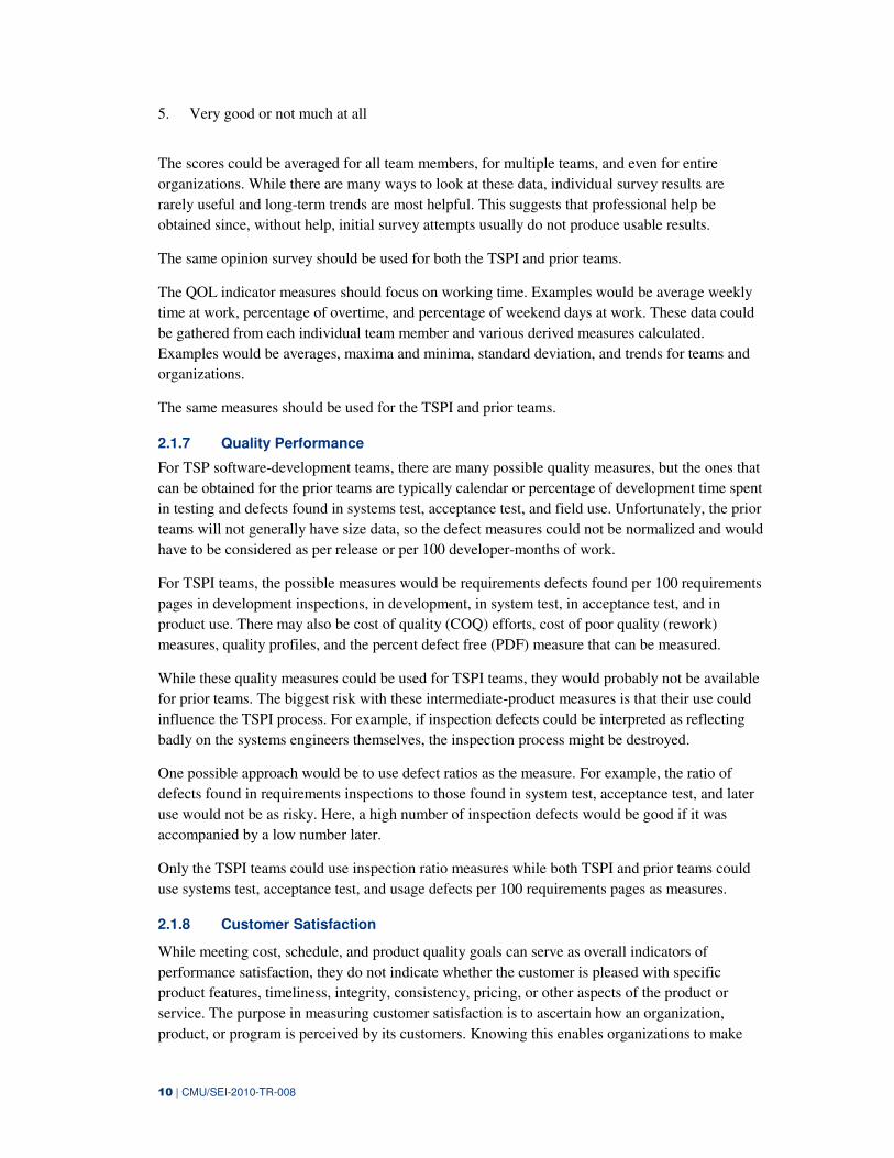
2.2.2 Before and After Using TSPI
Table 2 shows a “before using TSPI/after using TSPI” picture of the AV-8B Systems Engineering
Pilot Project. In addition to the measurement baseline, planning, tracking, use of defined
processes, and tools were also characterized:
Table 2: “Before/After TSPI” Picture of AV8B Systems Engineering Pilot Project Team
BEFORE TSPI AFTER TSPI
Planning • Very little baseline data
• Schedule determined by
management
• Components identified by
management
• Team leads divided the tasks
• No sizing information
• Effort guessed by similar
components in the past
• No quality goals were planned
• Engineering judgment used for
estimating
• 3 AV-8B Multi-team launches/year are
held—process used by the AV-8B
program to understand requirements
from management, assemble plans,
allocate work, and achieve commitment
to plans from management and team
members
• Overall plan for the year and the next-
phase plan are developed by the teams
• Work is allocated by the team and a
schedule is determined and committed to
by team members
• Size Measures for SE were established:
− DOORS Objects for requirements
− TWDs for testing (level of effort
(LOE) buckets were established to
account for the non-DOORS/non-
TWDS tasks)
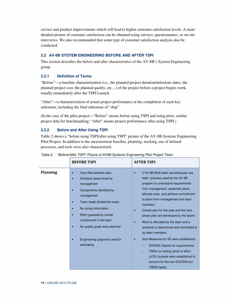
12 | CMU/SEI-2010-TR-008
• Starting to capture some baseline data
that can be used for estimation and
planning for the next launch:
− requirements Productivity Rate
varies between 3 and 9 DOORS
Objects per hour depending on the
complexity of the project
− rate of size growth decreasing from
23.6% in cycle 1 to 11.54% in cycle
2
− level 2 and level 3 requirements
sizes for H5.0 and H4.0 are
baselined for AVSYSS,WMC,MSC
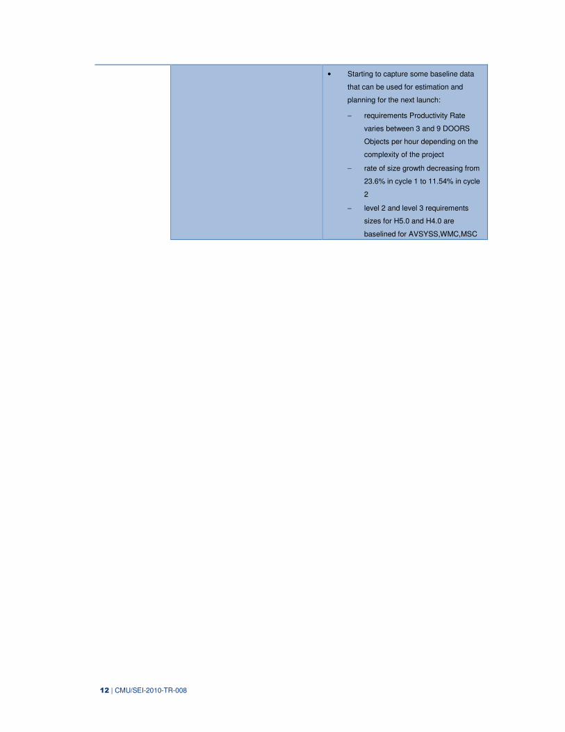
13 | CMU/SEI-2010-TR-008
Tracking • Earned value tracked using EVMS
by Team Lead
• EV defined as % complete
(subjective evaluation of work)
• Project Gantt Chart tracked by Team
Lead using MS Project
• Risks were not identified directly
• Management had weekly project
meetings and the status was verbally
presented then
• Work is broken down into small chunks
that can easily be tracked (tasks tracked
at a granularity of less than 10 hours)
• EV defined as 0 to 100 complete/not
complete (objective evaluation of work)
• Work tracked daily by team members
and discussed weekly in team
meetings—every team member knows
how they are performing to their
individual plan and the team plan weekly
− using team data to balance
workloads
− priorities and risks discussed
• Monthly status reports derived from
consolidated weekly reports by team
leader and presented to IPT Leads
• 12 team members were able to achieve
(on average) 18-22 on-project task hours
per week
− began by just logging their time
(began to understand that clock
time did not equal time on task)
− went above planned task hours (15
task hours/week) in 1st cycle
Schedule
Performance • Used EVMS data
• “Pretty good”
• Couldn’t tell if they were off of
schedule or by how much
• Able to set GOAL: <5% schedule slip
and measure performance against goals
• Actual <10% overrun
Cost
Performance • Used EVMS data
• “Costs were way over”
• Improving estimating ability due to
defined measures and processes
- cycle 1=49%
- cycle 2=95%
• Size estimates within 10%
• Effort estimates within 10%
Responsiveness • No way of measuring impact of
unplanned work
• Can plan for a percentage of unplanned
tasks
• Need to use data to negotiate
impact/trade-offs of unplanned work vs.
planned work
Quality of Life • Overtime was standard practice—
sometimes 25% or more
• Cycle 3 and Cycle 4 data shows that
overtime is reduced to 9-10% using TSPI
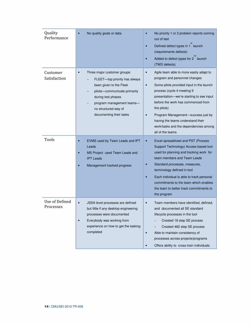
14 | CMU/SEI-2010-TR-008
Quality
Performance • No quality goals or data • No priority 1 or 2 problem reports coming
out of test
• Defined defect types in 1st
launch
(requirements defects)
• Added to defect types for 2nd
launch
(TWD defects)
Customer
Satisfaction
• Three major customer groups:
− FLEET—top priority has always
been given to the Fleet
− pilots—communicate primarily
during test phases
− program management teams—
no structured way of
documenting their tasks
• Agile team able to more easily adapt to
program and personnel changes
• Some pilots provided input in the launch
process (cycle 4 meeting 9
presentation—we’re starting to see input
before the work has commenced from
the pilots)
• Program Management—success just by
having the teams understand their
work/tasks and the dependencies among
all of the teams
Tools • EVMS used by Team Leads and IPT
Leads
• MS Project used Team Leads and
IPT Leads
• Management tracked progress
• Excel spreadsheet and PST (Process
Support Technology) Access-based tool
used for planning and tracking work for
team members and Team Leads
• Standard processes, measures,
terminology defined in tool
• Each individual is able to track personal
commitments to the team which enables
the team to better track commitments to
the program
Use of Defined
Processes • JSSA level processes are defined
but little if any desktop engineering
processes were documented
• Everybody was working from
experience on how to get the tasking
completed
• Team members have identified, defined,
and documented all SE standard
lifecycle processes in the tool
− Created 18 step SE process
− Created 482 step SE process
• Able to maintain consistency of
processes across projects/programs
• Offers ability to cross-train individuals
15 | CMU/SEI-2010-TR-008
2.3 CONDUCT RESEARCH
Before we adapt TSP for systems engineering, we needed to understand what systems engineering
is and what processes systems engineering encompasses. So, what do systems engineers do? We
learned that not only was there no single definition of what systems engineering was at NAVAIR
but also there was lack of consensus of what systems engineering is in the broader community. As
we think about devising processes, measures, and tools, it is helpful to understand what systems
engineering is and what it is not.
We have learned that there is no standard formula for performing systems engineering because
there is great diversity in the kinds of systems that are produced by systems engineering activities.
As a result, experienced systems engineering practitioners seem to tailor their favorite processes
to meet the needs of each specific project. Therefore, it is difficult to reach consensus on a single
systems engineering process because of the diversity of the applications and the varying
complexity of the systems to which the discipline is applied. Also as such, there are no standard
processes, measures, and benchmarks as there are in software engineering.
The International Council on Systems Engineering (INCOSE) defines Systems Engineering as an
interacting combination of elements viewed in relation to function. DoD Military Standard 499B
(Mil-Std 499B) defines systems engineering as an integrated composite of people, products, and
processes that provide a capability to satisfy a stated need or objective. These broad views of
systems engineering focus on defining customer needs and required functionality early in the
development cycle, documenting requirements, then proceeding with design synthesis and system
validation while considering the complete problem [ICSE 04].
Even though there are many different models for systems engineering, from a generic perspective,
each model addresses a problem definition, the development of a solution, the implementation of
the solution, and verification/testing of the solution. Some models also address technical and
project management. Functions are performed in parallel and repetitively, as better information on
the objective system become available.
In the absence of having documented systems engineering processes at NAVAIR, a Systems
Engineering Overview Process (SEOP) was developed (see Appendix D). These elements are as
follows.
• SysSpec, the system engineering process required to specify, guide, and verify the
development of a desired system, sub-system component, or enhancement
• SysReq, the system-engineering activities needed to produce and verify the various
requirements documents needed to guide developing the desired system, sub-system,
component, or enhancement
• SysTD, the system-engineering activities to produce the tests to verify that the resulting
system properly performs its intended functions
• INS, the unit process to inspect any work products produced by the system-engineering
activities
• DOC, the unit process to guide systems engineers in producing complete, clear, and high-
quality requirements, test, or other documents
16 | CMU/SEI-2010-TR-008
2.4 PILOT
This section describes the TSPI introduction strategy as well as the phases of the TSPI pilots.
Finally, this section articulates some initial observations of the AV-8B System Engineering Pilot
Project.
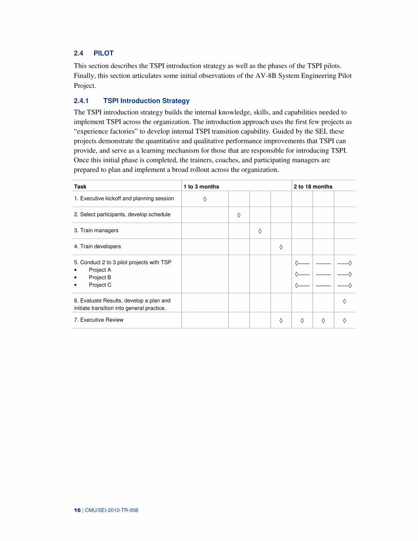
2.4.1 TSPI Introduction Strategy
The TSPI introduction strategy builds the internal knowledge, skills, and capabilities needed to
implement TSPI across the organization. The introduction approach uses the first few projects as
“experience factories” to develop internal TSPI transition capability. Guided by the SEI, these
projects demonstrate the quantitative and qualitative performance improvements that TSPI can
provide, and serve as a learning mechanism for those that are responsible for introducing TSPI.
Once this initial phase is completed, the trainers, coaches, and participating managers are
prepared to plan and implement a broad rollout across the organization.
Task 1 to 3 months 2 to 18 months
1. Executive kickoff and planning session ◊
2. Select participants, develop schedule ◊
3. Train managers ◊
4. Train developers ◊
5. Conduct 2 to 3 pilot projects with TSP
• Project A
• Project B
• Project C
◊−−−
◊−−−
◊−−−
−−−−
−−−−
−−−−
−−−◊
−−−◊
−−−◊
6. Evaluate Results, develop a plan and
initiate transition into general practice. ◊
7. Executive Review ◊ ◊ ◊ ◊
17 | CMU/SEI-2010-TR-008
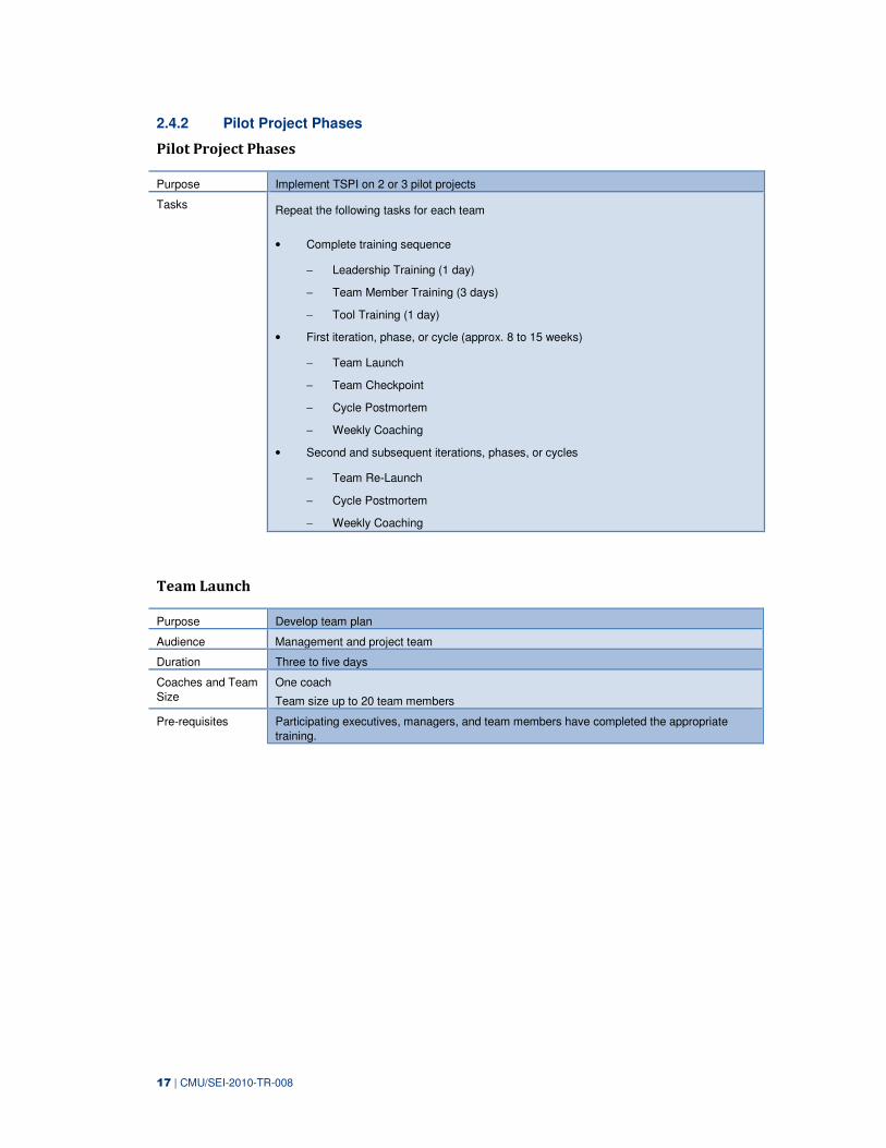
2.4.2 Pilot Project Phases
Pilot Project Phases
Purpose Implement TSPI on 2 or 3 pilot projects
Tasks Repeat the following tasks for each team
• Complete training sequence
− Leadership Training (1 day)
− Team Member Training (3 days)
− Tool Training (1 day)
• First iteration, phase, or cycle (approx. 8 to 15 weeks)
− Team Launch
− Team Checkpoint
− Cycle Postmortem
− Weekly Coaching
• Second and subsequent iterations, phases, or cycles
− Team Re-Launch
− Cycle Postmortem
− Weekly Coaching
Team Launch
Purpose Develop team plan
Audience Management and project team
Duration Three to five days
Coaches and Team
Size
One coach
Team size up to 20 team members
Pre-requisites Participating executives, managers, and team members have completed the appropriate
training.
18 | CMU/SEI-2010-TR-008
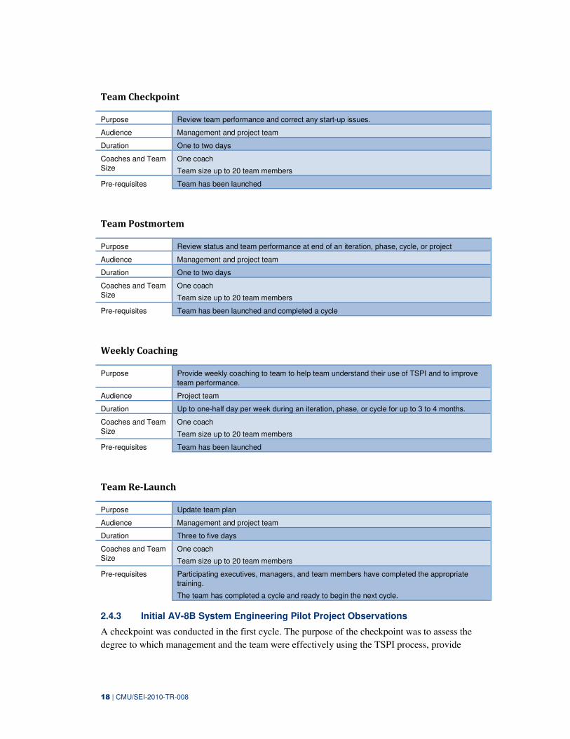
Team Checkpoint
Purpose Review team performance and correct any start-up issues.
Audience Management and project team
Duration One to two days
Coaches and Team
Size
One coach
Team size up to 20 team members
Pre-requisites Team has been launched
Team Postmortem
Purpose Review status and team performance at end of an iteration, phase, cycle, or project
Audience Management and project team
Duration One to two days
Coaches and Team
Size
One coach
Team size up to 20 team members
Pre-requisites Team has been launched and completed a cycle
Weekly Coaching
Purpose Provide weekly coaching to team to help team understand their use of TSPI and to improve
team performance.
Audience Project team
Duration Up to one-half day per week during an iteration, phase, or cycle for up to 3 to 4 months.
Coaches and Team
Size
One coach
Team size up to 20 team members
Pre-requisites Team has been launched
Team Re-Launch
Purpose Update team plan
Audience Management and project team
Duration Three to five days
Coaches and Team
Size
One coach
Team size up to 20 team members
Pre-requisites Participating executives, managers, and team members have completed the appropriate
training.
The team has completed a cycle and ready to begin the next cycle.
2.4.3 Initial AV-8B System Engineering Pilot Project Observations
A checkpoint was conducted in the first cycle. The purpose of the checkpoint was to assess the
degree to which management and the team were effectively using the TSPI process, provide
19 | CMU/SEI-2010-TR-008
findings from reviewing team and individual data and from interviews, and provide improvement
recommendations.
In general, the AV-8B team was off to a great start on using TSPI and having visibility into their
progress. They needed to improve effectiveness of team meetings with 100% participation from
all team members including the team leader. They needed to define and implement quality
practices to further capitalize on TSPI benefits to the process and product. The team placed a high
value on the launch process and developing plans. Tracking the work helped team members to
keep following the plan. The team meetings are used for coordination and communication with
team members and for off-loading and balancing tasks. The roles of planning manager, process
manager, flight test manager, and lab manager were being performed.
It was recommended that the team place a higher priority on holding regular, weekly team
meetings, with the team leader leading the meeting (team members reported that meetings are
more beneficial when the team leader is present). It was also recommended that the team meeting
be used as a forum to facilitate better information flow from management to the team, as well as
foster better communication of priority changes, scope changes, and rationale level of effort
(LOE) tasks that needed to be broken into finer categories and tracked with greater granularity.
The workbook phases needed to correspond to systems engineering phases and the terminology
needed to reflect systems engineering work. Discussion on how to define quality and track the
quality of the process and product occurred. A next step was analyze and use data to probe
down into the next level in the data and address reasons for not meeting commitments and taking
actions to get back on track

20 | CMU/SEI-2010-TR-008
21 | CMU/SEI-2010-TR-008
3 Guiding Principles
TSP and TSPI are based on some guiding principles.
1. Have a plan before the team commits to work.
Make commitments that you or your team can meet. Your commitment is likely part of your
organization’s commitment to someone to deliver a product or service at an agreed upon
time and for an agreed cost. Every business or organization depends on its people and/or
teams being able to do what they say they will do. Businesses or organizations that
consistently don’t meet their commitments will generally lose business and possibly not
survive. To be able to know that you or your team can meet a commitment, you need a plan
that details what you need to do, what resources you need, and how long it will take to
complete each part of the job. Then you can make a commitment for the job that you know
you can meet.
2. People doing the work should build the plans.
Individuals will strive hard to meet a commitment they made voluntarily and publicly. In
order for individuals to voluntarily and publicly commit to a plan, they need to participate in
making the plan. Only when individuals feel that it is their estimate of the work to be done,
and is based on how long it will take them to do the work, will they feel they own the plan
and can commit to the plan.
3. Where possible, base the plan on data.
To make a reasonably accurate plan, you need some historical data to base the estimates in
the plan on. Things like: (1) how many hours (or days) per week will you be able to work on
this; (2) how big is the product likely to be; (3) how long will it take to build a product this
size. Without some historical data on how many hours per week you are able to work on a
project, how big similar projects have been, and what the productivity rate has been on
similar projects, you will have to guess at these. While access to some industry rules of
thumb would certainly be helpful, the plan will generally be more accurate when it is based
on your own or your team’s data.
4. The plan should be based on a process and the people doing the work should own the
process.
Although you want to base your plan on historical data, you must also consider the process
used to do the work. Simply put, a process describes how to do something. If you work on
project A using one process and work on project B using a different process, then the data
from project A may not be useful for planning project B because of the process change. So,
to be able to make good plans, you want to use historical data from the same process or
similar processes. This means the processes need to be documented and plans need to be
based on the documented processes. The people doing the work need to agree to using the
process and this is best accomplished if they participate in defining and evolving the process.
Thus, they have an ownership in the process.
5. Plan in detail—break down work to logical units that can be tracked; roughly, tasks that take
less than 10 hours to complete.
22 | CMU/SEI-2010-TR-008
There are a couple of points behind this principle. The first has to do with planning accuracy
and the second with project tracking. With regard to planning accuracy, in general, the more
detailed the plan, the more accurate it is likely to be. This is because, while the estimate for
any single element of the plan is likely to be off by some percentage, when you combine
many estimates, some are over and some are under. If there are similar numbers of over and
under estimates, the errors will tend to cancel and the result will be much more accurate than
if the job had been estimated in one piece.
With regard to tracking accuracy, breaking tasks down to the level of 10 hours or less allows
individuals to know their current status against their plan to within 10 hours (note we are
assuming their tasks are serial). Since most individuals work 15 to 25 task hours per week,
this allows individuals to know their current status with a granularity of a day or two. On a
project basis with all team members tracking tasks that are 10 hours or less, this means the
project status is accurate to within a couple of days. Another reason for having tasks at the
10 hour or less level is that it motivates individual to finish the tasks. On a weekly basis, an
individual should be able to complete at least one task and possibly many if they are much
less than 10 hours. Being able to mark a task as complete motivates individuals on a daily
basis. Consider this—if an individual has tasks that are measured in weeks, it is easy to put
working on it off for a few hours or a day because there is still plenty of time to get it done.
But if a task is due today, it motivates the individual to get to work on it.
6. Follow a defined process and gather process data.
For your historical data to be meaningful, you need to know what process you used.
Therefore, you need to follow the defined process that the plan was based on. If that process
is inconvenient or broken, then the process should be fixed and the plan modified to reflect
the process change.
The process data needs to be gathered for a number of reasons. First, the process data is
needed to determine the project status. Without the data, you or the team won’t know what
the current project status is. Second, the process data is needed to understand how the
process is working. Are there any parts of the process that are not working as they should,
what changes need to be made to fix the use of the process? And finally, the process data is
needed as part of the historical data to be used in planning future projects.
7. Estimate based on size and use productivity to find effort.
Effort is generally related to size and normalizing historical effort data by size to get
productivity allows us to estimate new projects that have different sizes.
Relating effort to size is discussed below in item 11 on this list. Having a size measure that is
related to effort allows us to start by estimating the size of the product Once the product size
has been estimated, then productivity data from past projects can be used to estimate the
effort to build the product.
8. The team should own and manage its work. Use the plan and data to determine status.
When the team feels it owns the plan and is empowered to manage itself, the team will strive
to meet the voluntary and public commitment it made to management. If anyone, such as
management, changes the plan without the team buying into the change, the team may no
longer feel like it’s their plan. While they will still work to meet the plan, they no longer feel
the personal commitment they originally had; it is now someone else’s plan.
23 | CMU/SEI-2010-TR-008
A similar thing happens if management of the work is taken away from the team and
they feel “micro managed”.
9. Manage work to maintain commitments.
The team owns the plan and the commitment, and manages its work. In development, things
happen that aren’t planned for and plans need to be adjusted. The team is responsible for
determining how they can maintain their commitment to management. They may need to
revise their plan, put in some additional hours, ask management for assistance, or some
combination of these. In some cases it will not be possible to maintain the commitment and
the team will have to explain the situation to management and negotiate a new commitment
with management.
10. Keep management apprised of status against the commitments.
The team needs to inform management regularly about the status of the work against the
commitment the team made to them. Management empowered the team to manage its work,
but will get concerned about the project’s status if they don’t get regular project status
reports from the team that make sense to them. Management may begin to micro-manage the
project, causing the team to feel they have lost ownership of their project. That is why it is
very important for the team to provide management with a regular status report that shows
how the team is performing with respect to meeting their commitment to management.
11. Size measures should relate to effort. Size measures should also be precisely defined and
automatically countable.
First, to use size measures for planning, the size measure should relate to effort. What you
look for is a size measure that as size increases, the effort increases proportionally. Using
historical data, candidate size measures can be analyzed to find an appropriate size measure.
Additionally, it is important that the size measure be precisely defined. For instance, in
software, source lines of code (SLOC) are often used as a size measure. However, for a
given program the SLOC count can vary by a wide margin depending on how the lines are
counted. A precise definition is needed for what to count as a source line of code. A choice
must be made to count consistently, whether it be blank lines, comment lines, continuation
lines, or some other type. The same is true for any size measure; the size measure must be
precisely defined so that no matter who measures the size, everyone gets the same result.
Finally, counting the size measure should be automatable. For most size measures, counting
manually is time consuming and error prone. It is best to have an automated tool for
measuring product size.
12. Plans should be detailed to weekly tasks.
Plans are generally more accurate when they are more detailed. More detailed plans motivate
individuals to work on the tasks because the tasks have nearer term due dates and are
generally smaller. Also, smaller tasks allow the plan to be tracked at a more granular level
making it less likely there will be large status surprises.

24 | CMU/SEI-2010-TR-008
25 | CMU/SEI-2010-TR-008
4 Research Challenges
A number of research challenges would need to be addressed to appropriately extend TSP to be
applied in other engineering disciplines. Extending TSP to systems engineering teams required the
following activities:
Determining and establishing baseline performance for systems engineering and
acquisition work at NAVAIR. TSP is built on a solid software engineering foundation
where common processes already exist (e.g., requirements, design, code, test, etc.), base
measures exist, and performance data and baselines exist. However, this same foundation
does not exist for systems engineering since there is no standard definition for systems
engineering as well as no set of standard processes, measures, or performance data. So to
adapt TSP for systems engineering, TSP principles were reinstantiated for systems
engineering and we started to build a performance baseline for systems engineering.
At the time of this report no acquisition pilot project had been identified, thus baseline
performance for acquisition was not a focus of this effort. Towards the establishment of an
acquisition performance baseline, a questionnaire was developed and is included in Appendix
A of this report.
Developing prototype processes/process definitions/scripts for systems engineering and
acquisition management practices. We needed to define the content and structure
(processes/process definitions/scripts) of the overall Systems Engineering Process which
included (see Appendix D):
– SysSpec—the system engineering process required to specify, guide, and verify the
development of a desired system, sub-system, component, or enhancement
– SysReq—the system-engineering activities needed to produce and verify the various
requirements documents needed to guide developing the desired system, sub-system,
component, or enhancement
– SysTD—the system-engineering activities to produce the tests to verify that the resulting
system properly performs its intended functions
– INS—the unit process to inspect any work products produced by the system-engineering
activities
– DOC—the unit process to guide systems engineers in producing complete, clear, and
high-quality requirements, test, or other documents.
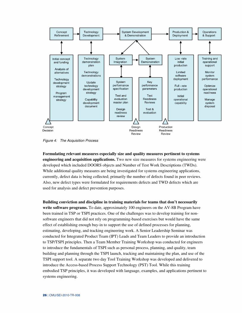
In addition, the content and structure (processes/process definitions/scripts) of each element of
the acquisition process was also defined including concept refinement, technology
development, system development and demonstration, production and deployment, and
operations and support (Figure 4). The overall acquisition process is described in Appendix C.
26 | CMU/SEI-2010-TR-008
Figure 4: The Acquisition Process
Formulating relevant measures especially size and quality measures pertinent to systems
engineering and acquisition applications. Two new size measures for systems engineering were
developed which included DOORS objects and Number of Test Work Descriptions (TWDs).
While additional quality measures are being investigated for systems engineering applications,
currently, defect data is being collected; primarily the number of defects found in peer reviews.
Also, new defect types were formulated for requirements defects and TWD defects which are
used for analysis and defect prevention purposes.
Building conviction and discipline in training materials for teams that don’t necessarily
write software programs. To date, approximately 100 engineers on the AV-8B Program have
been trained in TSP or TSPI practices. One of the challenges was to develop training for non-
software engineers that did not rely on programming-based exercises but would have the same
effect of establishing enough buy-in to support the use of defined processes for planning,
estimating, developing, and tracking engineering work. A Senior Leadership Seminar was
conducted for Integrated Product Team (IPT) Leads and Team Leaders to provide an introduction
to TSP/TSPI principles. Then a Team Member Training Workshop was conducted for engineers
to introduce the fundamentals of TSPI such as personal process, planning, and quality, team
building and planning through the TSPI launch, tracking and maintaining the plan, and use of the
TSPI support tool. A separate two day Tool Training Workshop was developed and delivered to
introduce the Access-based Process Support Technology (PST) Tool. While this training
embodied TSP principles, it was developed with language, examples, and applications pertinent to
systems engineering.
27 | CMU/SEI-2010-TR-008
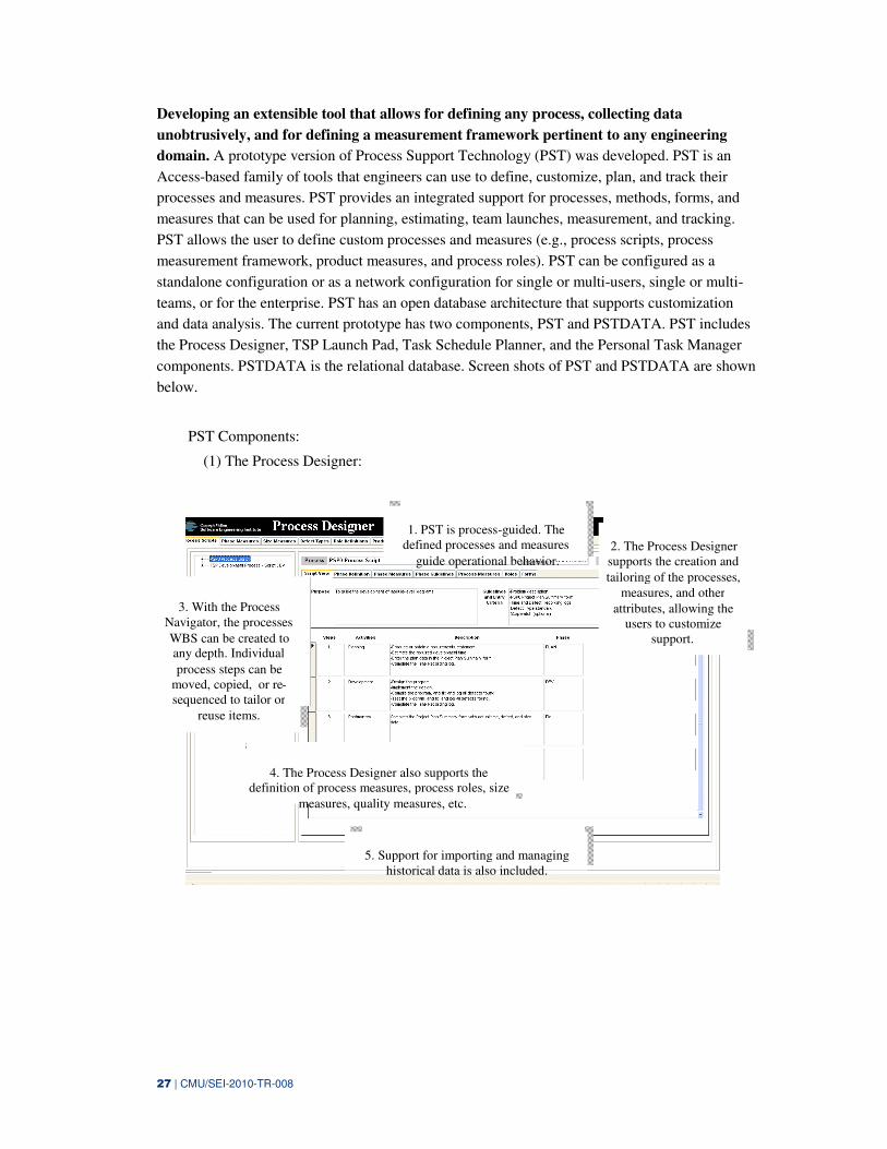
Developing an extensible tool that allows for defining any process, collecting data
unobtrusively, and for defining a measurement framework pertinent to any engineering
domain. A prototype version of Process Support Technology (PST) was developed. PST is an
Access-based family of tools that engineers can use to define, customize, plan, and track their
processes and measures. PST provides an integrated support for processes, methods, forms, and
measures that can be used for planning, estimating, team launches, measurement, and tracking.
PST allows the user to define custom processes and measures (e.g., process scripts, process
measurement framework, product measures, and process roles). PST can be configured as a
standalone configuration or as a network configuration for single or multi-users, single or multi-
teams, or for the enterprise. PST has an open database architecture that supports customization
and data analysis. The current prototype has two components, PST and PSTDATA. PST includes
the Process Designer, TSP Launch Pad, Task Schedule Planner, and the Personal Task Manager
components. PSTDATA is the relational database. Screen shots of PST and PSTDATA are shown
below.
PST Components:
(1) The Process Designer:
3. With the Process Navigator, the processes
WBS can be created to any depth. Individual
process steps can be moved, copied, or re-sequenced to tailor or
reuse items.
1. PST is process-guided. The defined processes and measures
guide operational behavior.2. The Process Designer supports the creation and
tailoring of the processes,
measures, and other
attributes, allowing the users to customize
support.
4. The Process Designer also supports the definition of process measures, process roles, size
measures, quality measures, etc.
5. Support for importing and managing historical data is also included.
28 | CMU/SEI-2010-TR-008
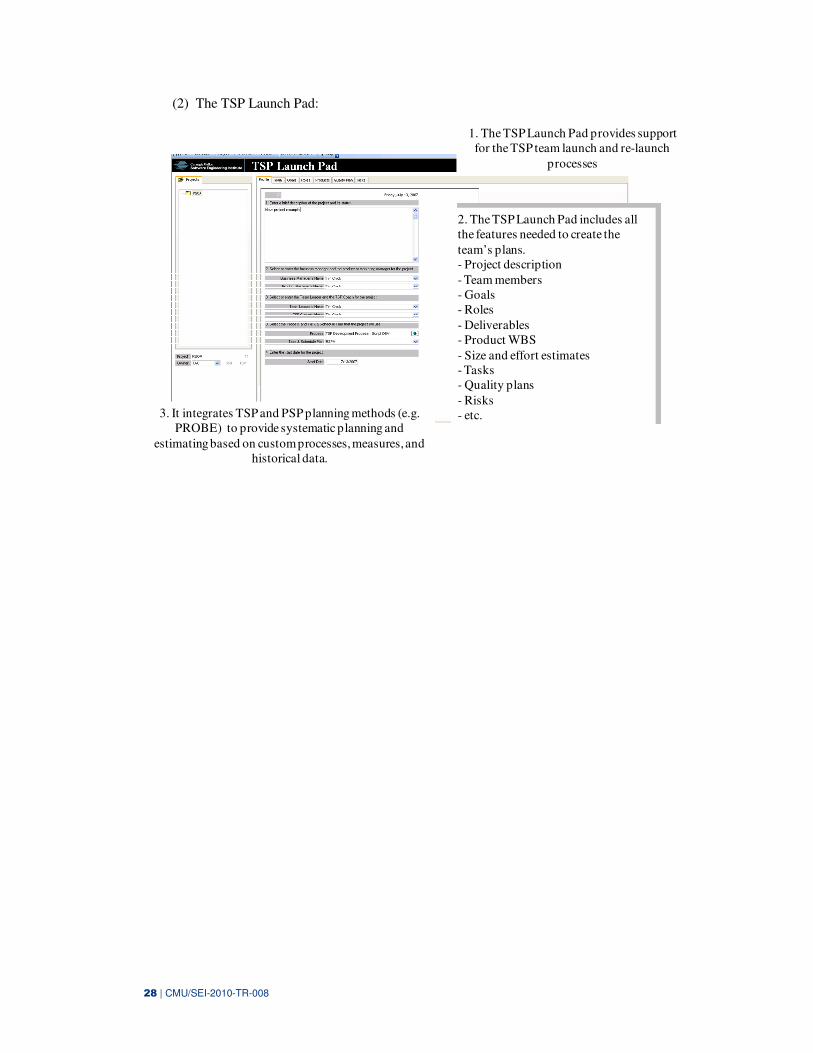
(2) The TSP Launch Pad:
2. The TSP Launch Pad includes all the features needed to create the
team’s plans.- Project description
- Team members- Goals- Roles
- Deliverables- Product WBS
- Size and effort estimates- Tasks- Quality plans
- Risks- etc.
1. The TSP Launch Pad provides support for the TSP team launch and re-launch
processes
3. It integrates TSP and PSP planning methods (e.g. PROBE) to provide systematic planning and
estimating based on custom processes, measures, and historical data.
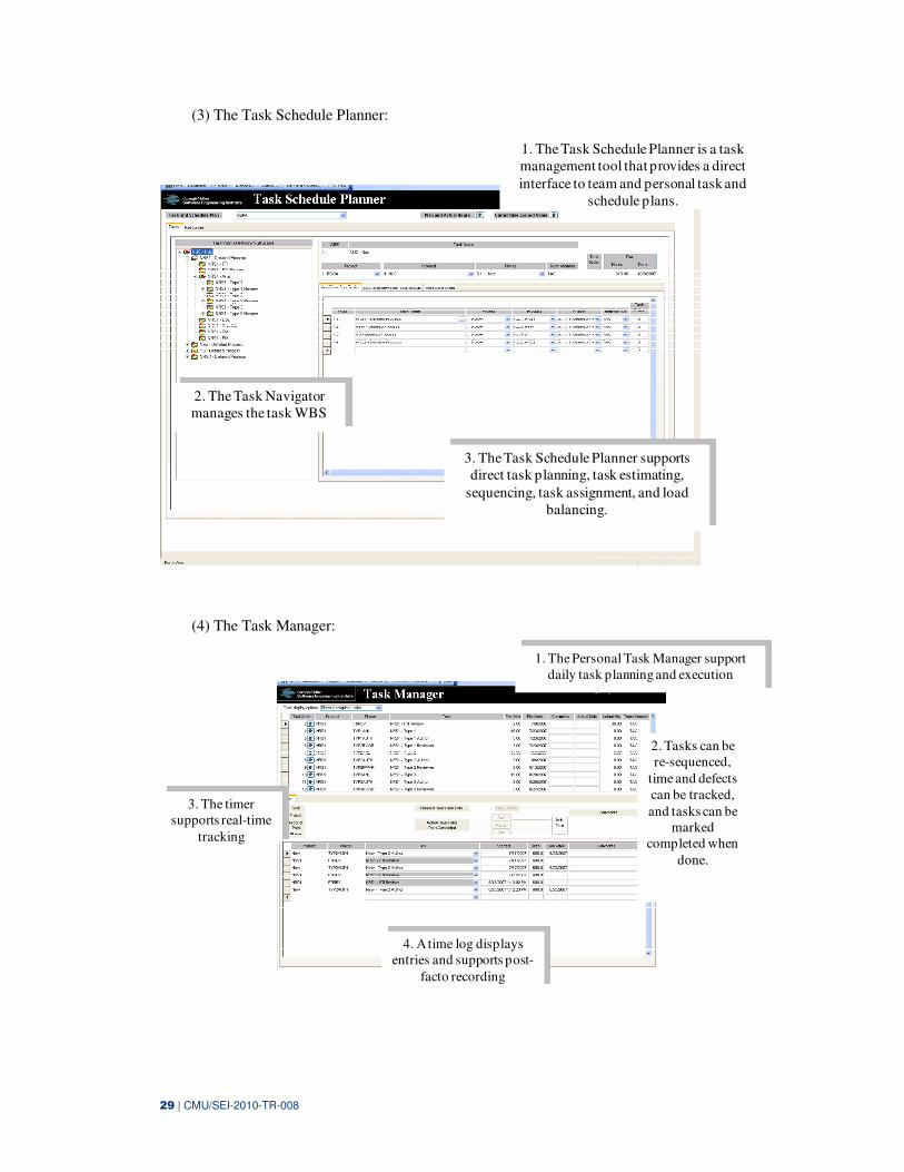
29 | CMU/SEI-2010-TR-008
(3) The Task Schedule Planner:
1. The Task Schedule Planner is a task management tool that provides a direct
interface to team and personal task and schedule plans.
3. The Task Schedule Planner supports direct task planning, task estimating,
sequencing, task assignment, and load balancing.
2. The Task Navigator manages the task WBS
(4) The Task Manager:
1. The Personal Task Manager support daily task planning and execution
3. The timer supports real-time
tracking
2. Tasks can be re-sequenced,
time and defects can be tracked,
and tasks can be marked
completed when
done.
4. A time log displays entries and supports post-
facto recording
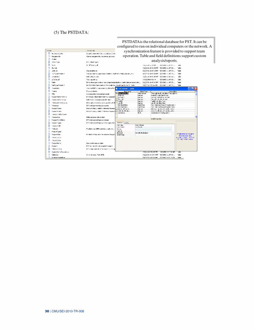
30 | CMU/SEI-2010-TR-008
(5) The PSTDATA:
PSTDATA is the relational database for PST. It can be configured to run on individual computers or the network. A
synchronization feature is provided to support team operation. Table and field definitions support custom
analysis/reports.
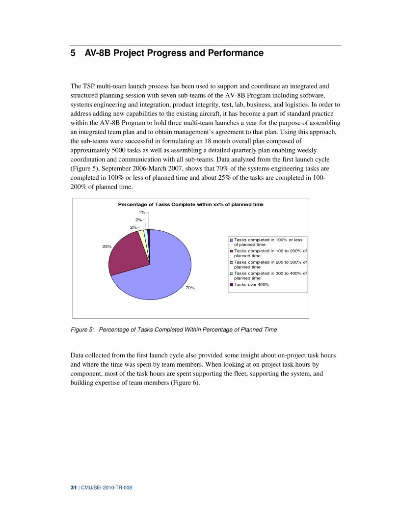
31 | CMU/SEI-2010-TR-008
5 AV-8B Project Progress and Performance
The TSP multi-team launch process has been used to support and coordinate an integrated and
structured planning session with seven sub-teams of the AV-8B Program including software,
systems engineering and integration, product integrity, test, lab, business, and logistics. In order to
address adding new capabilities to the existing aircraft, it has become a part of standard practice
within the AV-8B Program to hold three multi-team launches a year for the purpose of assembling
an integrated team plan and to obtain management’s agreement to that plan. Using this approach,
the sub-teams were successful in formulating an 18 month overall plan composed of
approximately 5000 tasks as well as assembling a detailed quarterly plan enabling weekly
coordination and communication with all sub-teams. Data analyzed from the first launch cycle
(Figure 5), September 2006-March 2007, shows that 70% of the systems engineering tasks are
completed in 100% or less of planned time and about 25% of the tasks are completed in 100-
200% of planned time.
Percentage of Tasks Complete within xx% of planned time
70%
25%
2%
2%
1%
Tasks completed in 100% or lessof planned time
Tasks completed in 100 to 200% of
planned time
Tasks completed in 200 to 300% of
planned time
Tasks completed in 300 to 400% of
planned time
Tasks over 400%
Figure 5: Percentage of Tasks Completed Within Percentage of Planned Time
Data collected from the first launch cycle also provided some insight about on-project task hours
and where the time was spent by team members. When looking at on-project task hours by
component, most of the task hours are spent supporting the fleet, supporting the system, and
building expertise of team members (Figure 6).
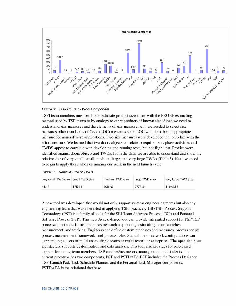
32 | CMU/SEI-2010-TR-008
Task Hours by Component
71.1
354.7
2.3 034.5 40.9 23.1 3.2
55.8
247200.8
18.3 8
552.5
94.7
797.9
12146 25
287
49.50
142200
479
180
652
12.467 70
0
100
200
300
400
500
600
700
800
900
1851
Rad
io
ALE-4
7
Allied
AVJMPS V
and
V
Analy
sis
APX-123
Blue
on B
lue
Build
1 M
isce
llaneo
us
Build
2 M
isce
llaneo
us
CAS Mis
sion
Data R
educ
tion
DMLG
B
EMU U
pgra
de
Enhan
ced P
avew
ay II
Experti
se B
uild
ing
FLE
Fleet
Supp
ort
HAE
JMPS S
ELC
DB
LPO
D
Man
agem
ent S
uppor
t
MAW
TS AVJM
PS Intro M
TT
NATIP R
eview O
T
Plug
and
Play
1
Str ike
Lin
k
SYSTEMTCTS
VMF
WM
CTS BO
MB C
OD
E Scr
ipt
Figure 6: Task Hours by Work Component
TSPI team members must be able to estimate product size either with the PROBE estimating
method used by TSP teams or by analogy to other products of known size. Since we need to
understand size measures and the elements of size measurement, we needed to select size
measures other than Lines of Code (LOC) measures since LOC would not be an appropriate
measure for non-software applications. Two size measures were developed that correlate with the
effort measure. We learned that two doors objects correlate to requirements phase activities and
TWDS appear to correlate with developing and running tests, but not flight test. Proxies were
identified against doors objects and TWDs. From the data, we are able to understand and show the
relative size of very small, small, medium, large, and very large TWDs (Table 3). Next, we need
to begin to apply these when estimating our work in the next launch cycle.
Table 3: Relative Size of TWDs
very small TWD size small TWD size medium TWD size large TWD size very large TWD size
44.17 175.64 698.42 2777.24 11043.55
A new tool was developed that would not only support systems engineering teams but also any
engineering team that was interested in applying TSPI practices. TSP/TSPI Process Support
Technology (PST) is a family of tools for the SEI Team Software Process (TSP) and Personal
Software Process (PSP). This new Access-based tool can provide integrated support for PSP/TSP
processes, methods, forms, and measures such as planning, estimating, team launches,
measurement, and tracking. Engineers can define custom processes and measures, process scripts,
process measurement framework, and process roles. Standalone or network configurations can
support single users or multi-users, single teams or multi-teams, or enterprises. The open database
architecture supports customization and data analysis. This tool also provides for role-based
support for teams, team members, TSP coaches/instructors, management, and students. The
current prototype has two components, PST and PSTDATA.PST includes the Process Designer,
TSP Launch Pad, Task Schedule Planner, and the Personal Task Manager components.
PSTDATA is the relational database.
33 | CMU/SEI-2010-TR-008
While some issues remain to be resolved, the AV-8B teams have defined an overall process and
separate processes for systems engineering/systems integration, product integrity, and lab efforts.
Approximately 800 steps overall have been defined in this new PST Tool. With this new tool, the
teams are able to generate tasks and produce estimates using historical data, organize products and
tasks in separate work breakdown systems (WBSs), track time and defects, and produce weekly
status/progress reports.

34 | CMU/SEI-2010-TR-008
35 | CMU/SEI-2010-TR-008
6 Lesson Learned
The critical success factors for this effort included having leadership support, management
support, coaching support, and customized training.
Willing and effective participants, particularly project and middle management support, were key
to successful adoption. TSPI adoption received strong and unequivocal support from the
Independent Product Team (IPT) Lead and the AV-8B technical management team. The
leadership team actively participated in the launches, checkpoints, and postmortems. It was
helpful for the leadership team to set aggressive goals and to also reward and recognize the team
for meeting commitments and following the processes.
We learned that effective coaching is crucial to project and TSPI adoption success. Coaches need
to:
• Assess a team’s progress on a “quality journey” and push the team as far as the team can go.
• Have pragmatic judgment about when to be flexible and when to hold the line on TSPI
principles.
• Assist in carefully selecting initial projects and shepherding their success.
• Work closely with the project manager—their influence is best when it is not visible outside
the team.
• Spend significant one-on-one time with project participants, especially in the beginning of
the project.
• Participate in weekly team meetings especially during the first 6-8 weeks of the project.
Also, a good training experience sets the stage for success. We need to ensure all team
participants (engineers, non-engineers, team leaders, as well as the leadership team) have
appropriate training. We need to provide customized training to allow developers to get to a TSPI
launch faster. We can develop and offer training based on the idea of “just in time (JIT).” For
example, instead of having all team members take a three-day Team Member Training Course
initially, we can roll-out the training and offer it in modules immediately prior to its usage.
The advantage of breaking apart the training into modules and offering the various modules
when a student is ready to use it, shortens the time between learning a new concept and
application on the job. For example, the following JIT training might be offered to TSPI
coaches:
• Conducting Checkpoints and Postmortems (1 day)
• Advanced Tool Training for Coaches (1 day)
• Analyzing Team Data (1 day)
36 | CMU/SEI-2010-TR-008
The following JIT training might be offered to team members:
• Team Member Refresher Training (2 days)
• TSPI Multi-team Processes (Team Roles, Leadership Team Roles, Cross Team
Coordination) (1 day)
• Launch Preparation (1/2 day)
• Conducting Effective Inspections
• Analyzing Team Data and Assembling Management Presentations (1 day)
37 | CMU/SEI-2010-TR-008
7 Summary/Conclusions
The SEI collaborated with the U.S. Naval Air Systems Command (NAVAIR) to extend the Team
Software Process (TSP) to systems engineering and acquisition management. The goal of the
effort was to improve productivity, quality, and project predictability by driving adoption of
TSPI. TSPI is aimed at extending TSP practices to other domains and to demonstrate that
distributed teams using tailorable process scripts, metrics and automated tool support can
deliver quality products and services on cost and schedule. We also wanted to determine if
extending TSP practices to systems engineering would result in measurable improvement.
The TSPI strategy was to:
• ensure that NAVAIR leadership expected and required delivery of systems/software
products with the highest quality
• identify pilot team(s) that were enthusiastic about using TSPI
• ensure that each project was staffed for success with a strong coach
• not to go too far, too fast because any failed pilot project would make future ones more
difficult
• use pilot teams as internal references and sources of champions and future coaches
• build internal coaching capacity within each adopting organization
In addition, critical success factors for this effort including having strong leadership support,
management support, coaching support, and effective, relevant, and timely training.
Extending TSP to systems engineering teams required:
• Determining and establishing baseline performance for systems engineering work at
NAVAIR. TSP is built on a solid software engineering foundation where common processes
already exist (e.g., requirements, design, code, test …), base measures exist, and
performance data and baselines exist. However, this same foundation does not exist for
systems engineering since there is no standard definition for systems engineering as well as
no set of standard processes, measures, or performance data. So to adapt TSP for systems
engineering, TSP principles were re-instantiated for systems engineering.
• Developing prototype processes/process definitions/scripts for systems engineering and
acquisition management practices. The content and structure (processes/process
definitions/scripts) of the overall Systems Engineering Process were defined including: the
system engineering process required to specify, guide, and verify the development of a
desired system, sub-system, component, or enhancement; the system engineering activities
needed to produce and verify the various requirements documents needed to guide
developing the desired system, sub-system, component, or enhancement; the system
engineering activities to produce the tests to verify that the resulting system properly
performs its intended functions; the unit process to inspect any work products produced by
the system engineering activities; and the unit process to guide systems engineers in
38 | CMU/SEI-2010-TR-008
producing complete, clear, and high-quality requirements, test, or other documents. In
addition, the content and structure (processes/process definitions/scripts) of each element of
the Acquisition Process was also defined including Concept Refinement, Technology
Development, System Development and Demonstration, Production and Deployment, and
Operations and Support.
• Formulating relevant measures especially size and quality measures pertinent to systems
engineering and acquisition applications. Two new size measures for systems engineering
were developed which included DOORS objects and Number of Test Work Descriptions
(TWDs). While additional quality measures are being investigated for systems engineering
applications, currently defect data is being collected, primarily the number of defects found
in peer reviews. Also, new defect types were formulated for requirements defects and TWD
defects which are used for analysis and defect prevention purposes.
• Building conviction and discipline in training materials for teams that don’t necessarily write
software programs. Training was developed for non-software engineers including a one day
Senior Leadership Seminar (for IPT Leads and Team Leaders), a three day Team Member
Training, and a two day Tool Training Workshop. While this training embodied TSP
principles it was developed with language, examples, and applications pertinent to systems
engineering.
• Developing an extensible tool that allows for defining any process, collecting data
unobtrusively, and for defining a measurement framework pertinent to any engineering
domain. A prototype version of Process Support Technology (PST) was developed. PST is
an Access-based family of tools that engineers can use to define, customize, plan, and track
their processes and measures.
While we are just starting to see some of the initial benefits of applying TSPI, our early results
show some encouraging trends: In general, the pilot team planned their work, gathered data on
their work, and tracked status against their plans. The team is practicing more disciplined methods
for planning and executing their work, meeting their missions, and they are beginning to see some
cost savings. In addition, the pilot team is inspiring other NAVAIR 4.0 System Support Activities
(SSAs) to pursue process improvement activities.
The AV-8B Systems Engineering pilot project team is changing the way they do their work and
beginning to see some results similar to those realized by TSP teams. Through the pilot effort, we
are seeing some benefits with respect to establishing a systems engineering baseline, establishing
planning and tracking practices, establishing standard processes, measures, and tools, some
performance improvements in schedule, cost, and quality and improvements in employee work
life balance and customer responsiveness.
1. Establishing a Systems Engineering Baseline
Through the AV-8B Systems Engineering Pilot Project, we are beginning to establish a
baseline for systems engineering performance at NAVAIR that can be used for estimating,
planning, and tracking project/programs.
− Requirements Productivity Rate varies between 3 and 9 DOORS Objects per hour
depending on the complexity of the project.
39 | CMU/SEI-2010-TR-008
− By just tracking size growth, the team was able to decrease the rate of size growth from
23.6% in cycle 1 to 11.54% in cycle 2.
− Level 2 and Level 3 requirements sizes for release H5.0 and release H4.0 are baselined
for three components.
− Some of the sentiments of the team leader are: “Prior to TSPI, we made estimates in a
bubble. Now we are establishing and maintaining baselines for all of our releases, which
allows us to make better estimates and more realistic plans and schedules.”
2. Establishing Planning Practices
Planning at the program and team level is now accomplished by holding three AV-8B multi-
team launches a year. This process is used by the AV-8B program to understand
requirements from management, assemble plans, allocate work, and achieve commitment to
plans from management and team members. The overall plan for the year and the next-phase
plan are developed by the teams, work is allocated by the team, and the schedule is
determined and committed to by team members.
3. Establishing Tracking Practices
For tracking purposes, work is broken down into small chunks that can easily be tracked
(tasks are tracked at a granularity of less than 10 hours). Work is tracked daily by team
members and discussed weekly in team meetings—every team member knows how they are
performing to their individual plan and the team plan weekly. Monthly status reports are
derived from the consolidated weekly reports by the team leader and presented to the IPT
Leads.
− By just logging their time, the team began to understand that clock time did not equal
time on task.
− Twelve team members were able to achieve (on average) 18-22 on-project task hours per
week. The team performed well above the planned task hours of 15 task hours per week
in the 1st cycle.
− Engineers embrace project planning and tracking. Each individual is able to track
personal commitments to the team which enables the team to better track commitments
to the program. Tracking the work is helping team members to stay on track: “I need to
stop doing X to get back on track. It is very easy to see the impact daily and weekly of
not working to the plan.”
4. Standard Processes, Measures, and Tools
Standard processes, measures, terminology, and tools were developed and used by the AV-
8B Program.
− The Excel Spreadsheet and PST (Process Support Technology) Access-based Tool were
used for estimating, planning, and tracking work for team members and team leads.
− Team members identified, defined, and documented all systems engineering standard
lifecycle processes in the tool. The team:
− Defined an 18 step overall systems engineering process
− Defined a 482 step detailed systems engineering process
− Through the defined processes, NAVAIR was able to maintain consistency of
processes across projects/programs. The defined processes also offered the ability to
cross-train individuals. “We have a team concept across our program with all of the
40 | CMU/SEI-2010-TR-008
subteams (systems engineering, product integrity, software, test, lab, etc…). We also
have a common set of processes and metrics to help all of the teams better
communicate and address dependencies across the teams.”
5. Schedule, Cost, and Quality Performance Trends
− Schedule Performance: The team established goal of less than 5% schedule slip and
measured performance against goals. The actual performance was less than 10%
overrun.
− Cost Performance: The estimating ability improved due to defined measures and
processes from 49% in cycle 1 to 95% in cycle 2. Size and effort estimates were within
10%.
− Quality Performance: There were no priority 1 or 2 problem reports coming out of test.
6. Employee Work Life Balance
TSPI helped improve employee work life balance. Overtime was decreased from being
standard practice—sometimes 25% or more to “occasional” overtime hours (less than 10%).
7. Customer Responsiveness
Customer responsiveness has improved to the fleet, the naval aviators, and to the internal
program managers. The systems engineering team is a more agile team able to more easily
adapt to program and personnel changes. The pilots are beginning to provide input early in
the project, during the launch process, before the work has commenced instead of providing
feedback during the test phases. Program management feels that the TSP/TSPI efforts are a
success because the teams understand their work and the dependencies among all of the
teams. The team can also plan for a percentage of unplanned tasks and uses their data to
negotiate impact and trade-offs of unplanned work to planned work.
In order to build integrated teams and quality systems from requirements to field deployment, we
need to put in place the right foundation consisting of estimation and planning processes, team
processes, development and management practices, effective and timely training, and launch,
coaching, and operational support. For programs to succeed there is a need for more than
technical domain expertise. Projects/Programs require a level of coordination and communication
among teams and team members. Establishing this collaborative environment means preparing
executives, managers, and engineers to work together, to agree on project goals, and to organize
into sub-teams that can build a quality product within schedule and cost constraints. This report
shows what is possible when teams use TSPI to meet these critical business needs by delivering
high quality systems on schedule and with improved productivity.
41 | CMU/SEI-2010-TR-008
8 Next Steps
Next steps involve continuing with the activities outlined on the roadmap for lessons that will feed
into broad-scale transition at NAVAIR. We need to do the following:
• Incorporate lessons from the pilot project and revise processes, training, tools, and measures
• Track ongoing use and benefit of TSPI
• Capitalize further on initial results and benefits by putting in place quality practices
• Expand NAVAIR use as warranted, especially in an acquisition management setting
• Evaluate prototype tools and courses for broader use—plan, develop, and deliver JIT to
support coaches and teams
• Devise training for authorizing change agents (coaches, instructors, etc…)
• Develop an authorization or certification approach
• Document an organizational implementation or staged introduction strategy
• Integrate the TSP and TSPI product suites
To further validate the TSPI approach in an acquisition management setting, we recommend the
following study:
1. Conduct a proof of concept pilot to address acquisition management using TSPI with a
Program Office.
− develop plan and timeline
− collect data on the program by administering the questionnaire in Appendix A to the
program managers for the TSPI Acquisition Pilot Project
− present plan to Program Office
2. Plan, develop, and test TSPI training materials.
− Conduct TSPI executive seminar
− Conduct planning session with acquirers and developers
− Deliver TSPI Team Member Training
3. Conduct kick-off meeting with the Program
4. Pilot TSPI. The following are desirable characteristics for a TSPI pilot project:
− During the pilot period, the development team and their management must use PSP and
TSPI.
− Each pilot should be of modest size, ideally a single team of a maximum of 12 to 15
team members.
− The group should have early adopters on both sides of the “acquirer/developer”
relationship.
− There should be a senior leadership champion for the pilot.
5. Collect progress measures (see Appendix B).
6. Communicate results of the effort to the stakeholders identified previously.

42 | CMU/SEI-2010-TR-008
43 | CMU/SEI-2010-TR-008
9 Appendix A: Questionnaire for Interviewing DoD Program
Managers for TSPI Acquisition Pilot Project
The following questions are intended to begin a dialogue on program management issues. All
questions may not apply to all program management or acquisition situations.
1. Interviewee information
a. Name:
b. Title:
c. Mailing Address:
d. Email Address:
e. Voice Telephone Number:
2. Interviewee Background/Experience/Project Environment
The following questions are asked to help us understand your level of experience with
systems/software management and the environment in which you work.
a. How many years of program management experience do you have?
b. How many years of systems/software management experience do you have?
c. Briefly describe the systems/software projects for which you are currently responsible.
i. # In-house developers/# Contractor developers
ii. # Systems engineers/# Contractor systems engineers
iii. Scale
a) # Lines of code
b) # Users supported (if applicable)
c) # End items supported (if applicable)
3. Current Systems/Software Project Management Tools
The following questions are asked to help us understand how you currently manage projects.
a. Are you currently using a schedule estimating tool? If so, which one?
b. Do you use earned value to track projects? If so, which method?
c. Are you currently using an effort (cost or hours) estimating tool for your
systems/software projects? If so, which one?
d. How do you track quality statistics?
e. How do you track total ownership costs?
f. How do you track the cost of quality?
g. How do you track requirements satisfaction?
44 | CMU/SEI-2010-TR-008
4. Current Issues/Challenges
We would like you to describe any current project management issues and challenges you
are facing.
a. Do you have systems/software project schedule issues or challenges?
b. Do you have systems/software project cost issues or challenges?
c. Do you have systems/software project quality issues or challenges?
d. Do you have systems/software project performance issues or challenges?
5. Management Scenarios
Do you currently have the capability or would you like to have the capability to answer the
following questions?
a. Is my project on schedule?
b. Is my project on budget?
c. Are we going to get a quality product?
d. Will it do what we said it would do?
e. How do I know when my project is in trouble?
f. My project has a first article test milestone in 9 months, my developer has been
working for 18 months, and next week is “code complete.” How do I know whether
I’m getting the straight story from my contractor?
g. How do I convincingly communicate program status information up the line?
h. Please describe other questions you would like to be able to answer that are not listed
here.
6. Proposed Measures5
If we could show you how to use these measures to answer the key questions you have about
a program’s status and likely future performance, would these be useful to you?
a. Schedule predictability:
i. Earned value (expressed as a percent of total projected task hours)
ii. Projected completion date vs. planned completion date
iii. Trend (plotted over time) of projected vs. actual completion dates
b. Effort predictability:
i. Billed or charged hours vs. planned hours (this reflects no change from current practice; for instance, billing for 40-hour weeks)
ii. Actual task hours vs. planned task hours
c. Quality:
i. Defects per thousand lines of code (KLOC), planned and actual, by phase 5 Overall assumptions: These metrics will be derived from a detailed TSPI Plan. Development work is measured
on all activities (time, size, defects, and date) and includes actual and planned data for all activities. Earned val-ue has different meanings within various communities. The definition used here is effort in hours on a task ÷ to-tal projected task hours. This definition needs to be made explicit in all of the team’s documentation. Effort measures are task hours, not calendar hours.
45 | CMU/SEI-2010-TR-008
ii. Percent KLOC defect free by program phase (defects affect operation of systems)
iii. Quality profile plots (as defined in the Team Software Process)
d. Total ownership cost:
i. Cost of program development (program initiation to initial operational capability)
ii. Cost of program maintenance (cost to maintain product after initial operational capability)
e. Cost of quality:
i. Time (hours) spent and percent of total project time (hours) spent in each development phase
ii. Percent of total development time spent in appraisal (walkthroughs, reviews, and inspections)
iii. Percent of total development time spent in rework (compile and test)
f. Delivered quality
i. Number of acceptance test defects (user acceptance or operational suitability tests)
ii. Acceptance test defects per KLOC
g. Cycle time:
i. Time in days from project initiation to initial operational capability or first production article delivery
ii. Percent of cycle time spent in all test phases
Please describe any other measures not listed here that you that you believe you need to manage
projects effectively:
1.
2.
3.
Thank you for your support of the NAVAIR TSPI effort.

46 | CMU/SEI-2010-TR-008
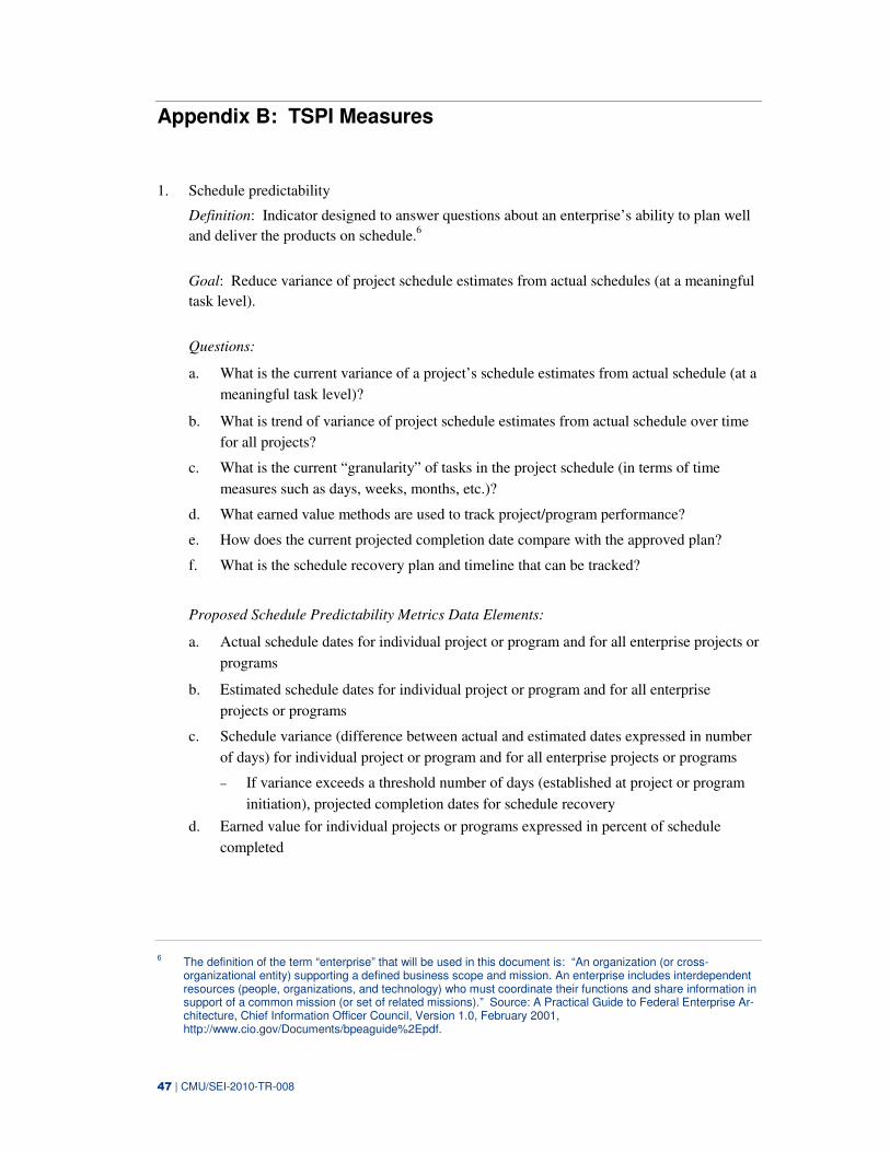
47 | CMU/SEI-2010-TR-008
Appendix B: TSPI Measures
1. Schedule predictability
Definition: Indicator designed to answer questions about an enterprise’s ability to plan well
and deliver the products on schedule.6
Goal: Reduce variance of project schedule estimates from actual schedules (at a meaningful
task level).
Questions:
a. What is the current variance of a project’s schedule estimates from actual schedule (at a
meaningful task level)?
b. What is trend of variance of project schedule estimates from actual schedule over time
for all projects?
c. What is the current “granularity” of tasks in the project schedule (in terms of time
measures such as days, weeks, months, etc.)?
d. What earned value methods are used to track project/program performance?
e. How does the current projected completion date compare with the approved plan?
f. What is the schedule recovery plan and timeline that can be tracked?
Proposed Schedule Predictability Metrics Data Elements:
a. Actual schedule dates for individual project or program and for all enterprise projects or
programs
b. Estimated schedule dates for individual project or program and for all enterprise
projects or programs
c. Schedule variance (difference between actual and estimated dates expressed in number
of days) for individual project or program and for all enterprise projects or programs
− If variance exceeds a threshold number of days (established at project or program
initiation), projected completion dates for schedule recovery
d. Earned value for individual projects or programs expressed in percent of schedule
completed
6 The definition of the term “enterprise” that will be used in this document is: “An organization (or cross-
organizational entity) supporting a defined business scope and mission. An enterprise includes interdependent resources (people, organizations, and technology) who must coordinate their functions and share information in support of a common mission (or set of related missions).” Source: A Practical Guide to Federal Enterprise Ar-chitecture, Chief Information Officer Council, Version 1.0, February 2001, http://www.cio.gov/Documents/bpeaguide%2Epdf.
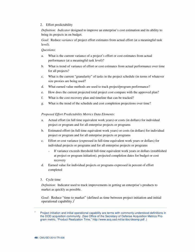
48 | CMU/SEI-2010-TR-008
2. Effort predictability
Definition: Indicator designed to improve an enterprise’s cost estimation and its ability to
bring its projects in on budget.
Goal: Reduce variance of project effort estimates from actual effort (at a meaningful task
level).
Questions:
a. What is the current variance of a project’s effort or cost estimates from actual
performance (at a meaningful task level)?
b. What is trend of variance of effort or cost estimates from actual performance over time
for all projects?
c. What is the current “granularity” of tasks in the project schedule (in terms of whatever
size proxies are being used?
d. What earned value methods are used to track project/program performance?
e. How does the current projected total project cost compare with the approved plan?
f. What is the cost recovery plan and timeline that can be tracked?
g. What is the trend of the schedule and cost completion projections over time?
Proposed Effort Predictability Metrics Data Elements:
a. Actual effort (in full time equivalent work years) or costs (in dollars) for individual
project or program and for all enterprise projects or programs
b. Estimated effort (in full time equivalent work years) or costs (in dollars) for individual
project or program and for all enterprise projects or programs
c. Effort or cost variance (expressed in full-time equivalent work years or dollars) for
individual projects or programs and for all enterprise projects or programs
− If variance exceeds threshold full-time equivalent work years or dollars (established
at project or program initiation), projected completion dates for budget or cost
recovery
d. Earned value for individual projects or programs expressed in percent of effort
completed
3. Cycle time
Definition: Indicator used to track improvements in getting an enterprise’s products to
market as quickly as possible.
Goal: Reduce “time to market” (defined as time between project initiation and initial operational capability.)7
7 Project initiation and initial operational capability are terms with commonly-understood definitions in
the DOD acquisition community. (See Office of the Secretary of Defense Acquisition Metrics Pro-gram metric, “Product Realization Time,” http://www.acq.osd.mil/ar/doc/deamp.pdf .)
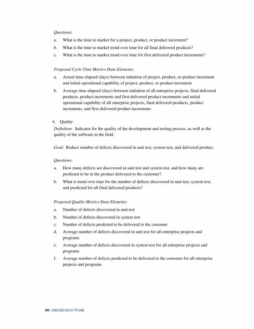
49 | CMU/SEI-2010-TR-008
Questions:
a. What is the time to market for a project, product, or product increment?
b. What is the time to market trend over time for all final delivered products?
c. What is the time to market trend over time for first delivered product increments?
Proposed Cycle Time Metrics Data Elements:
a. Actual time elapsed (days) between initiation of project, product, or product increment
and initial operational capability of project, product, or product increment
b. Average time elapsed (days) between initiation of all enterprise projects, final delivered
products, product increments and first-delivered product increments and initial
operational capability of all enterprise projects, final delivered products, product
increments, and first-delivered product increments
4. Quality
Definition: Indicator for the quality of the development and testing process, as well as the
quality of the software in the field.
Goal: Reduce number of defects discovered in unit test, system test, and delivered product.
Questions:
a. How many defects are discovered in unit test and system test, and how many are
predicted to be in the product delivered to the customer?
b. What is trend over time for the number of defects discovered in unit test, system test,
and predicted for all final delivered products?
Proposed Quality Metrics Data Elements:
a. Number of defects discovered in unit test
b. Number of defects discovered in system test
c. Number of defects predicted to be delivered to the customer
d. Average number of defects discovered in unit test for all enterprise projects and
programs
e. Average number of defects discovered in system test for all enterprise projects and
programs
f. Average number of defects predicted to be delivered to the customer for all enterprise
projects and programs
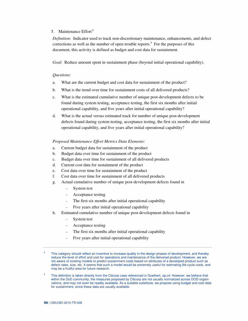
50 | CMU/SEI-2010-TR-008
5. Maintenance Effort 8
Definition: Indicator used to track non-discretionary maintenance, enhancements, and defect
corrections as well as the number of open trouble reports.9 For the purposes of this
document, this activity is defined as budget and cost data for sustainment.
Goal: Reduce amount spent in sustainment phase (beyond initial operational capability).
Questions:
a. What are the current budget and cost data for sustainment of the product?
b. What is the trend over time for sustainment costs of all delivered products?
c. What is the estimated cumulative number of unique post-development defects to be
found during system testing, acceptance testing, the first six months after initial
operational capability, and five years after initial operational capability?
d. What is the actual versus estimated track for number of unique post-development
defects found during system testing, acceptance testing, the first six months after initial
operational capability, and five years after initial operational capability?
Proposed Maintenance Effort Metrics Data Elements:
a. Current budget data for sustainment of the product
b. Budget data over time for sustainment of the product
c. Budget data over time for sustainment of all delivered products
d. Current cost data for sustainment of the product
e. Cost data over time for sustainment of the product
f. Cost data over time for sustainment of all delivered products
g. Actual cumulative number of unique post-development defects found in
− System test
− Acceptance testing
− The first six months after initial operational capability
− Five years after initial operational capability
h. Estimated cumulative number of unique post-development defects found in
− System test
− Acceptance testing
− The first six months after initial operational capability
− Five years after initial operational capability
8 This category should reflect an incentive to increase quality in the design phases of development, and thereby
reduce the level of effort and cost for operations and maintenance of the delivered product. However, we are not aware of existing models to predict sustainment costs based on attributes of a developed product such as defect rates, size, etc. It seems that such a model would be extremely useful for estimating life-cycle costs, and may be a fruitful area for future research.
9 This definition is taken directly from the Citicorp case referenced in Goethert, op.cit. However, we believe that within the DoD community, the measures proposed by Citicorp are not usually normalized across DOD organi-zations, and may not even be readily available. As a suitable substitute, we propose using budget and cost data for sustainment, since these data are usually available.
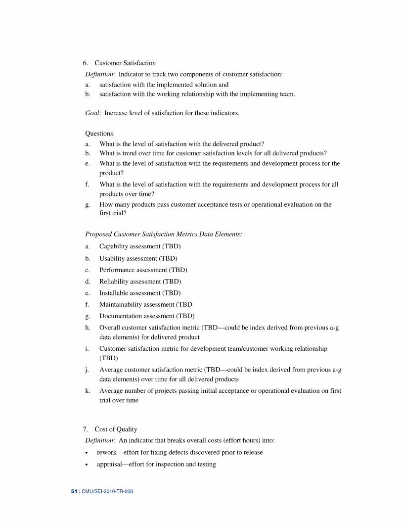
51 | CMU/SEI-2010-TR-008
6. Customer Satisfaction
Definition: Indicator to track two components of customer satisfaction:
a. satisfaction with the implemented solution and
b. satisfaction with the working relationship with the implementing team.
Goal: Increase level of satisfaction for these indicators.
Questions:
a. What is the level of satisfaction with the delivered product?
b. What is trend over time for customer satisfaction levels for all delivered products?
e. What is the level of satisfaction with the requirements and development process for the
product?
f. What is the level of satisfaction with the requirements and development process for all
products over time?
g. How many products pass customer acceptance tests or operational evaluation on the
first trial?
Proposed Customer Satisfaction Metrics Data Elements:
a. Capability assessment (TBD)
b. Usability assessment (TBD)
c. Performance assessment (TBD)
d. Reliability assessment (TBD)
e. Installable assessment (TBD)
f. Maintainability assessment (TBD
g. Documentation assessment (TBD)
h. Overall customer satisfaction metric (TBD—could be index derived from previous a-g
data elements) for delivered product
i. Customer satisfaction metric for development team/customer working relationship
(TBD)
j. Average customer satisfaction metric (TBD—could be index derived from previous a-g
data elements) over time for all delivered products
k. Average number of projects passing initial acceptance or operational evaluation on first
trial over time
7. Cost of Quality
Definition: An indicator that breaks overall costs (effort hours) into:
• rework—effort for fixing defects discovered prior to release
• appraisal—effort for inspection and testing
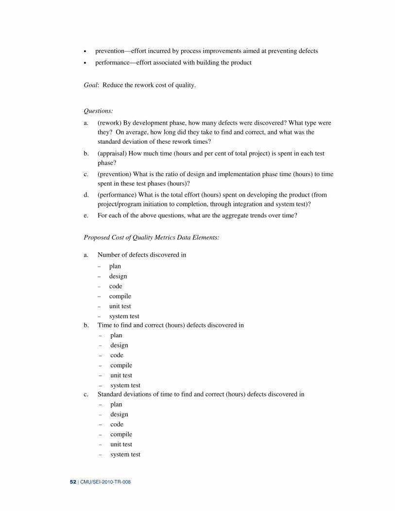
52 | CMU/SEI-2010-TR-008
• prevention—effort incurred by process improvements aimed at preventing defects
• performance—effort associated with building the product
Goal: Reduce the rework cost of quality.
Questions:
a. (rework) By development phase, how many defects were discovered? What type were
they? On average, how long did they take to find and correct, and what was the
standard deviation of these rework times?
b. (appraisal) How much time (hours and per cent of total project) is spent in each test
phase?
c. (prevention) What is the ratio of design and implementation phase time (hours) to time
spent in these test phases (hours)?
d. (performance) What is the total effort (hours) spent on developing the product (from
project/program initiation to completion, through integration and system test)?
e. For each of the above questions, what are the aggregate trends over time?
Proposed Cost of Quality Metrics Data Elements:
a. Number of defects discovered in
− plan
− design
− code
− compile
− unit test
− system test
b. Time to find and correct (hours) defects discovered in
− plan
− design
− code
− compile
− unit test
− system test
c. Standard deviations of time to find and correct (hours) defects discovered in
− plan
− design
− code
− compile
− unit test
− system test
53 | CMU/SEI-2010-TR-008
d. Time (hours) spent in development phase
− plan
− design
− code
− compile
− unit test
− system test
e. Percent of total project time (hours) spent in development phase
− plan
− design
− code
− compile
− unit test
− system test
f. Ratio of time spent (hours) in development and implementation phases to time spent
(hours) in test phases.
g. Trends over time for all of the above

54 | CMU/SEI-2010-TR-008
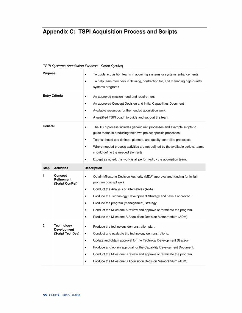
55 | CMU/SEI-2010-TR-008
Appendix C: TSPI Acquisition Process and Scripts
TSPI Systems Acquisition Process - Script SysAcq
Purpose • To guide acquisition teams in acquiring systems or systems enhancements
• To help team members in defining, contracting for, and managing high-quality
systems programs
Entry Criteria • An approved mission need and requirement
• An approved Concept Decision and Initial Capabilities Document
• Available resources for the needed acquisition work
• A qualified TSPI coach to guide and support the team
General • The TSPI process includes generic unit processes and example scripts to
guide teams in producing their own project-specific processes.
• Teams should use defined, planned, and quality-controlled processes.
• Where needed process activities are not defined by the available scripts, teams
should define the needed elements.
• Except as noted, this work is all performed by the acquisition team.
Step Activities Description
1 Concept
Refinement
(Script ConRef)
• Obtain Milestone Decision Authority (MDA) approval and funding for initial
program concept work.
• Conduct the Analysis of Alternatives (AoA).
• Produce the Technology Development Strategy and have it approved.
• Produce the program (management) strategy.
• Conduct the Milestone A review and approve or terminate the program.
• Produce the Milestone A Acquisition Decision Memorandum (ADM).
2 Technology
Development
(Script TechDev)
• Produce the technology demonstration plan.
• Conduct and evaluate the technology demonstrations.
• Update and obtain approval for the Technical Development Strategy.
• Produce and obtain approval for the Capability Development Document.
• Conduct the Milestone B review and approve or terminate the program.
• Produce the Milestone B Acquisition Decision Memorandum (ADM).
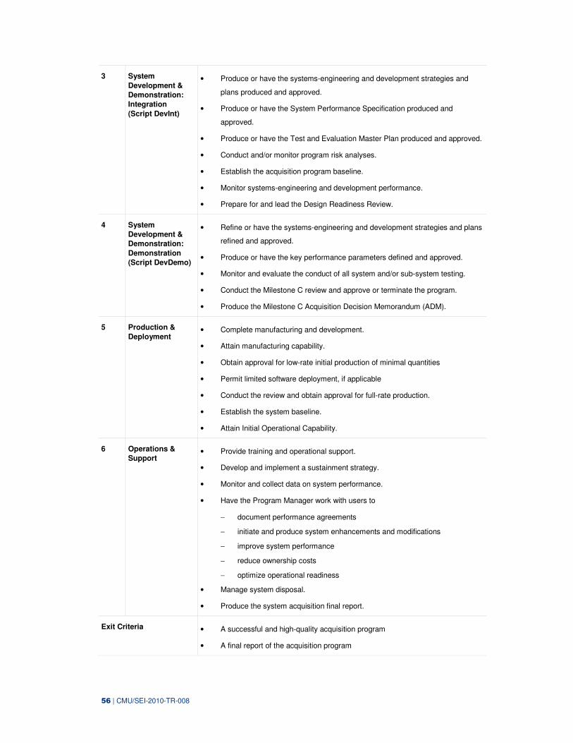
56 | CMU/SEI-2010-TR-008
3 System
Development &
Demonstration:
Integration
(Script DevInt)
• Produce or have the systems-engineering and development strategies and
plans produced and approved.
• Produce or have the System Performance Specification produced and
approved.
• Produce or have the Test and Evaluation Master Plan produced and approved.
• Conduct and/or monitor program risk analyses.
• Establish the acquisition program baseline.
• Monitor systems-engineering and development performance.
• Prepare for and lead the Design Readiness Review.
4 System
Development &
Demonstration:
Demonstration
(Script DevDemo)
• Refine or have the systems-engineering and development strategies and plans
refined and approved.
• Produce or have the key performance parameters defined and approved.
• Monitor and evaluate the conduct of all system and/or sub-system testing.
• Conduct the Milestone C review and approve or terminate the program.
• Produce the Milestone C Acquisition Decision Memorandum (ADM).
5 Production &
Deployment • Complete manufacturing and development.
• Attain manufacturing capability.
• Obtain approval for low-rate initial production of minimal quantities
• Permit limited software deployment, if applicable
• Conduct the review and obtain approval for full-rate production.
• Establish the system baseline.
• Attain Initial Operational Capability.
6 Operations &
Support • Provide training and operational support.
• Develop and implement a sustainment strategy.
• Monitor and collect data on system performance.
• Have the Program Manager work with users to
− document performance agreements
− initiate and produce system enhancements and modifications
− improve system performance
− reduce ownership costs
− optimize operational readiness
• Manage system disposal.
• Produce the system acquisition final report.
Exit Criteria • A successful and high-quality acquisition program
• A final report of the acquisition program
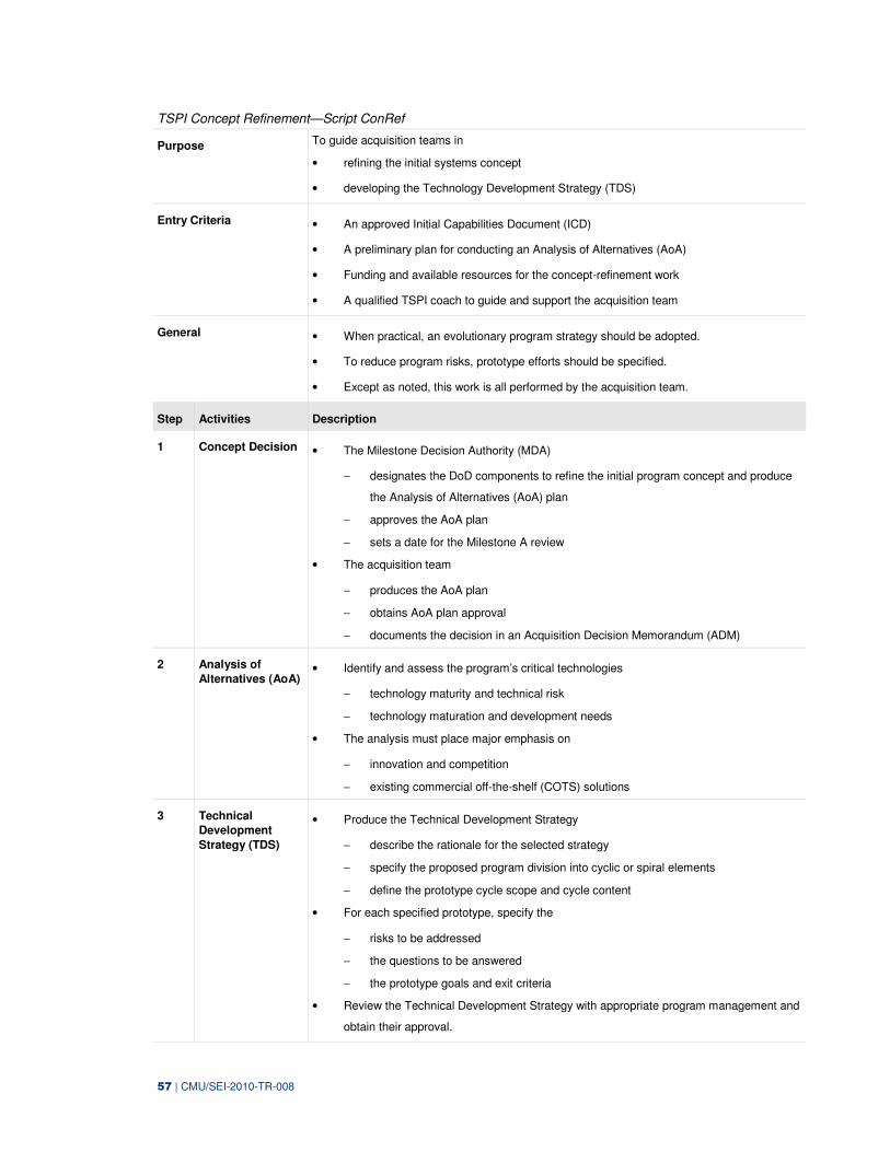
57 | CMU/SEI-2010-TR-008
TSPI Concept Refinement—Script ConRef
Purpose To guide acquisition teams in
• refining the initial systems concept
• developing the Technology Development Strategy (TDS)
Entry Criteria • An approved Initial Capabilities Document (ICD)
• A preliminary plan for conducting an Analysis of Alternatives (AoA)
• Funding and available resources for the concept-refinement work
• A qualified TSPI coach to guide and support the acquisition team
General • When practical, an evolutionary program strategy should be adopted.
• To reduce program risks, prototype efforts should be specified.
• Except as noted, this work is all performed by the acquisition team.
Step Activities Description
1 Concept Decision • The Milestone Decision Authority (MDA)
− designates the DoD components to refine the initial program concept and produce
the Analysis of Alternatives (AoA) plan
− approves the AoA plan
− sets a date for the Milestone A review
• The acquisition team
− produces the AoA plan
− obtains AoA plan approval
− documents the decision in an Acquisition Decision Memorandum (ADM)
2 Analysis of
Alternatives (AoA) • Identify and assess the program’s critical technologies
− technology maturity and technical risk
− technology maturation and development needs
• The analysis must place major emphasis on
− innovation and competition
− existing commercial off-the-shelf (COTS) solutions
3 Technical
Development
Strategy (TDS)
• Produce the Technical Development Strategy
− describe the rationale for the selected strategy
− specify the proposed program division into cyclic or spiral elements
− define the prototype cycle scope and cycle content
• For each specified prototype, specify the
− risks to be addressed
− the questions to be answered
− the prototype goals and exit criteria
• Review the Technical Development Strategy with appropriate program management and
obtain their approval.
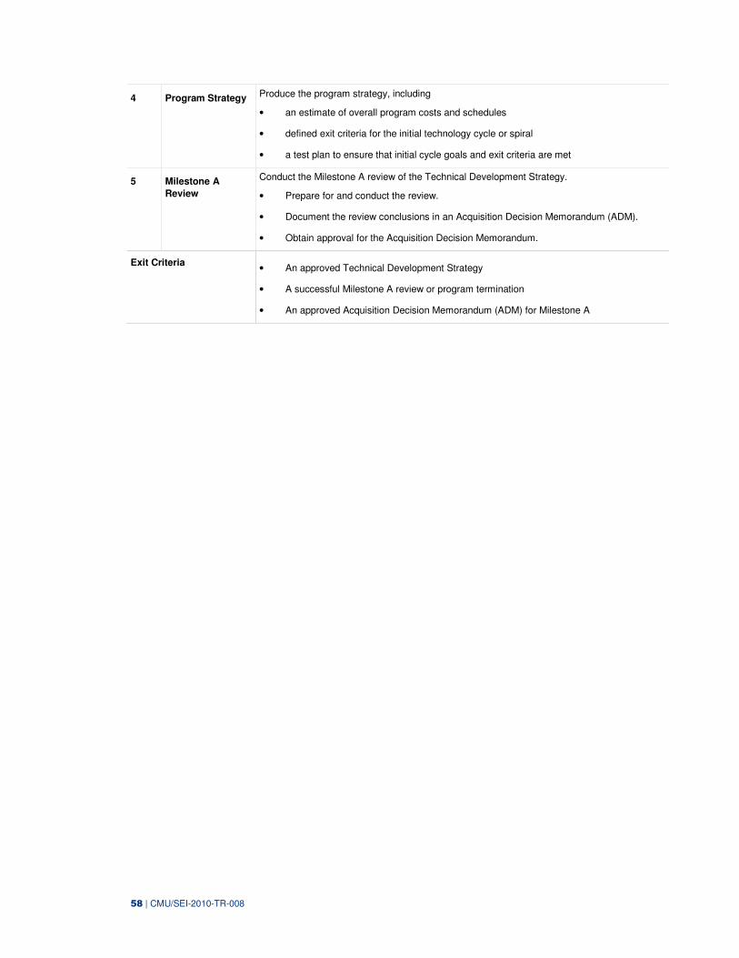
58 | CMU/SEI-2010-TR-008
4 Program Strategy Produce the program strategy, including
• an estimate of overall program costs and schedules
• defined exit criteria for the initial technology cycle or spiral
• a test plan to ensure that initial cycle goals and exit criteria are met
5 Milestone A
Review
Conduct the Milestone A review of the Technical Development Strategy.
• Prepare for and conduct the review.
• Document the review conclusions in an Acquisition Decision Memorandum (ADM).
• Obtain approval for the Acquisition Decision Memorandum.
Exit Criteria • An approved Technical Development Strategy
• A successful Milestone A review or program termination
• An approved Acquisition Decision Memorandum (ADM) for Milestone A
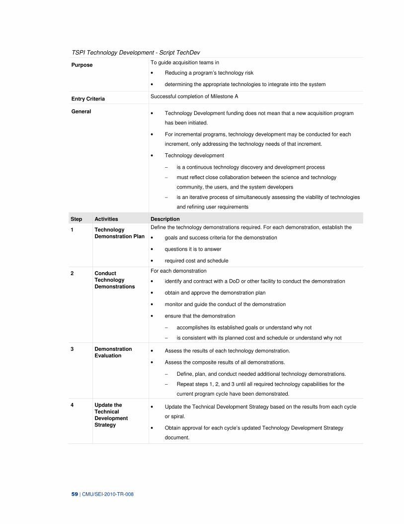
59 | CMU/SEI-2010-TR-008
TSPI Technology Development - Script TechDev
Purpose To guide acquisition teams in
• Reducing a program’s technology risk
• determining the appropriate technologies to integrate into the system
Entry Criteria Successful completion of Milestone A
General • Technology Development funding does not mean that a new acquisition program
has been initiated.
• For incremental programs, technology development may be conducted for each
increment, only addressing the technology needs of that increment.
• Technology development
− is a continuous technology discovery and development process
− must reflect close collaboration between the science and technology
community, the users, and the system developers
− is an iterative process of simultaneously assessing the viability of technologies
and refining user requirements
Step Activities Description
1 Technology
Demonstration Plan
Define the technology demonstrations required. For each demonstration, establish the
• goals and success criteria for the demonstration
• questions it is to answer
• required cost and schedule
2 Conduct
Technology
Demonstrations
For each demonstration
• identify and contract with a DoD or other facility to conduct the demonstration
• obtain and approve the demonstration plan
• monitor and guide the conduct of the demonstration
• ensure that the demonstration
− accomplishes its established goals or understand why not
− is consistent with its planned cost and schedule or understand why not
3 Demonstration
Evaluation • Assess the results of each technology demonstration.
• Assess the composite results of all demonstrations.
− Define, plan, and conduct needed additional technology demonstrations.
− Repeat steps 1, 2, and 3 until all required technology capabilities for the
current program cycle have been demonstrated.
4 Update the
Technical
Development
Strategy
• Update the Technical Development Strategy based on the results from each cycle
or spiral.
• Obtain approval for each cycle’s updated Technology Development Strategy
document.
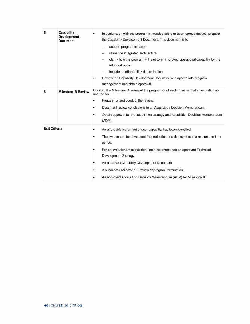
60 | CMU/SEI-2010-TR-008
5 Capability
Development
Document
• In conjunction with the program’s intended users or user representatives, prepare
the Capability Development Document. This document is to
− support program initiation
− refine the integrated architecture
− clarify how the program will lead to an improved operational capability for the
intended users
− include an affordability determination
• Review the Capability Development Document with appropriate program
management and obtain approval.
6 Milestone B Review Conduct the Milestone B review of the program or of each increment of an evolutionary acquisition.
• Prepare for and conduct the review.
• Document review conclusions in an Acquisition Decision Memorandum.
• Obtain approval for the acquisition strategy and Acquisition Decision Memorandum
(ADM).
Exit Criteria • An affordable increment of user capability has been identified.
• The system can be developed for production and deployment in a reasonable time
period.
• For an evolutionary acquisition, each increment has an approved Technical
Development Strategy.
• An approved Capability Development Document
• A successful Milestone B review or program termination
• An approved Acquisition Decision Memorandum (ADM) for Milestone B
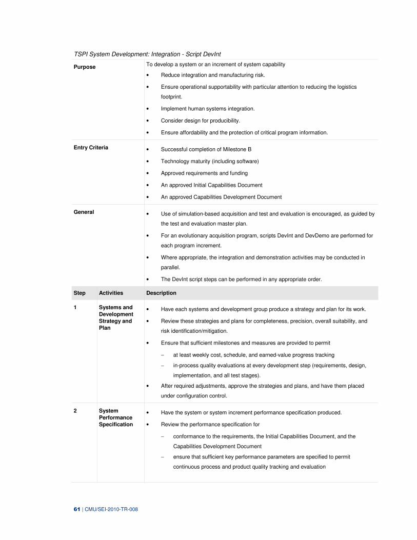
61 | CMU/SEI-2010-TR-008
TSPI System Development: Integration - Script DevInt
Purpose To develop a system or an increment of system capability
• Reduce integration and manufacturing risk.
• Ensure operational supportability with particular attention to reducing the logistics
footprint.
• Implement human systems integration.
• Consider design for producibility.
• Ensure affordability and the protection of critical program information.
Entry Criteria • Successful completion of Milestone B
• Technology maturity (including software)
• Approved requirements and funding
• An approved Initial Capabilities Document
• An approved Capabilities Development Document
General • Use of simulation-based acquisition and test and evaluation is encouraged, as guided by
the test and evaluation master plan.
• For an evolutionary acquisition program, scripts DevInt and DevDemo are performed for
each program increment.
• Where appropriate, the integration and demonstration activities may be conducted in
parallel.
• The DevInt script steps can be performed in any appropriate order.
Step Activities Description
1 Systems and
Development
Strategy and
Plan
• Have each systems and development group produce a strategy and plan for its work.
• Review these strategies and plans for completeness, precision, overall suitability, and
risk identification/mitigation.
• Ensure that sufficient milestones and measures are provided to permit
− at least weekly cost, schedule, and earned-value progress tracking
− in-process quality evaluations at every development step (requirements, design,
implementation, and all test stages).
• After required adjustments, approve the strategies and plans, and have them placed
under configuration control.
2 System
Performance
Specification
• Have the system or system increment performance specification produced.
• Review the performance specification for
− conformance to the requirements, the Initial Capabilities Document, and the
Capabilities Development Document
− ensure that sufficient key performance parameters are specified to permit
continuous process and product quality tracking and evaluation
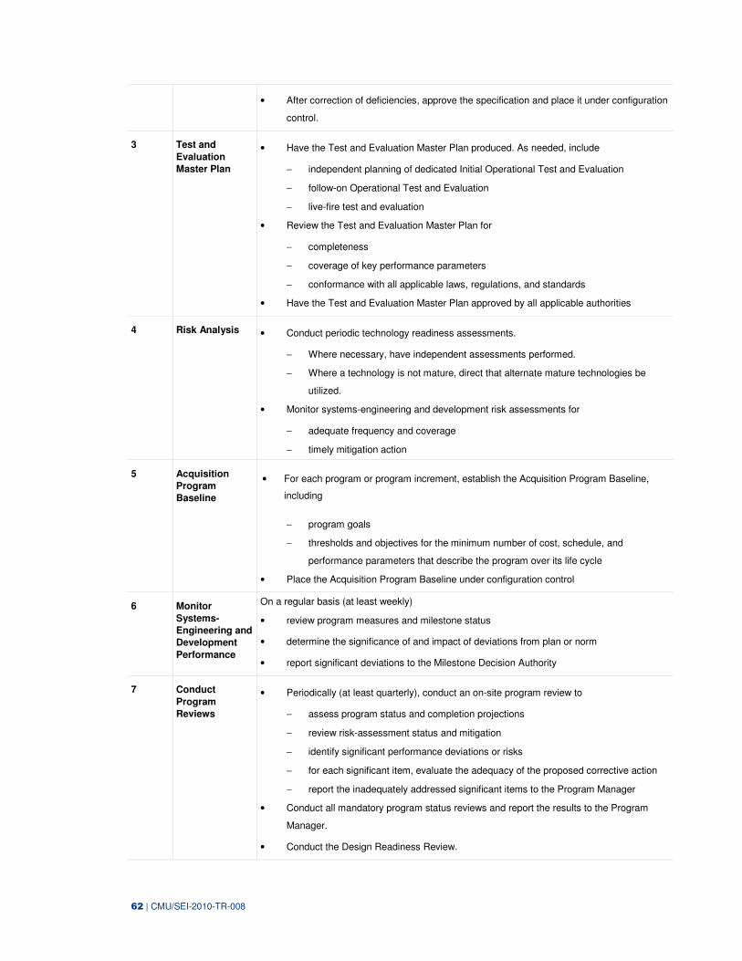
62 | CMU/SEI-2010-TR-008
• After correction of deficiencies, approve the specification and place it under configuration
control.
3 Test and
Evaluation
Master Plan
• Have the Test and Evaluation Master Plan produced. As needed, include
− independent planning of dedicated Initial Operational Test and Evaluation
− follow-on Operational Test and Evaluation
− live-fire test and evaluation
• Review the Test and Evaluation Master Plan for
− completeness
− coverage of key performance parameters
− conformance with all applicable laws, regulations, and standards
• Have the Test and Evaluation Master Plan approved by all applicable authorities
4 Risk Analysis • Conduct periodic technology readiness assessments.
− Where necessary, have independent assessments performed.
− Where a technology is not mature, direct that alternate mature technologies be
utilized.
• Monitor systems-engineering and development risk assessments for
− adequate frequency and coverage
− timely mitigation action
5 Acquisition
Program
Baseline
• For each program or program increment, establish the Acquisition Program Baseline,
including
− program goals
− thresholds and objectives for the minimum number of cost, schedule, and
performance parameters that describe the program over its life cycle
• Place the Acquisition Program Baseline under configuration control
6 Monitor
Systems-
Engineering and
Development
Performance
On a regular basis (at least weekly)
• review program measures and milestone status
• determine the significance of and impact of deviations from plan or norm
• report significant deviations to the Milestone Decision Authority
7 Conduct
Program
Reviews
• Periodically (at least quarterly), conduct an on-site program review to
− assess program status and completion projections
− review risk-assessment status and mitigation
− identify significant performance deviations or risks
− for each significant item, evaluate the adequacy of the proposed corrective action
− report the inadequately addressed significant items to the Program Manager
• Conduct all mandatory program status reviews and report the results to the Program
Manager.
• Conduct the Design Readiness Review.
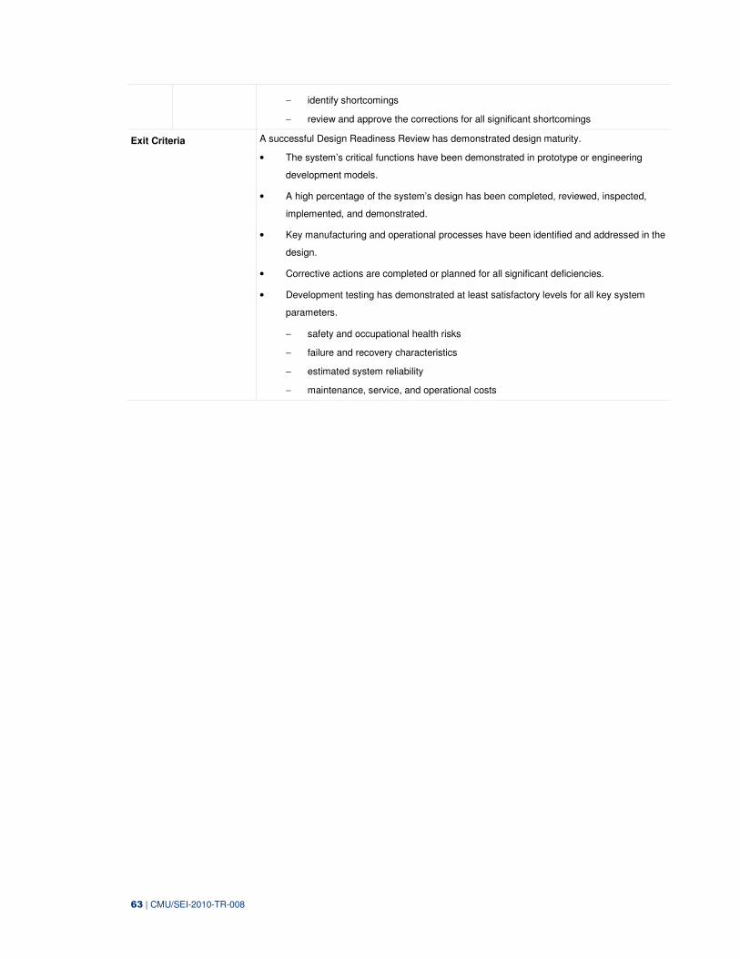
63 | CMU/SEI-2010-TR-008
− identify shortcomings
− review and approve the corrections for all significant shortcomings
Exit Criteria A successful Design Readiness Review has demonstrated design maturity.
• The system’s critical functions have been demonstrated in prototype or engineering
development models.
• A high percentage of the system’s design has been completed, reviewed, inspected,
implemented, and demonstrated.
• Key manufacturing and operational processes have been identified and addressed in the
design.
• Corrective actions are completed or planned for all significant deficiencies.
• Development testing has demonstrated at least satisfactory levels for all key system
parameters.
− safety and occupational health risks
− failure and recovery characteristics
− estimated system reliability
− maintenance, service, and operational costs
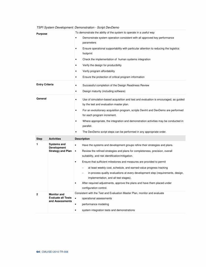
64 | CMU/SEI-2010-TR-008
TSPI System Development: Demonstration - Script DevDemo
Purpose To demonstrate the ability of the system to operate in a useful way
• Demonstrate system operation consistent with all approved key performance
parameters
• Ensure operational supportability with particular attention to reducing the logistics
footprint
• Check the implementation of human systems integration
• Verify the design for producibility
• Verify program affordability
• Ensure the protection of critical program information
Entry Criteria • Successful completion of the Design Readiness Review
• Design maturity (including software)
General • Use of simulation-based acquisition and test and evaluation is encouraged, as guided
by the test and evaluation master plan.
• For an evolutionary acquisition program, scripts DevInt and DevDemo are performed
for each program increment.
• Where appropriate, the integration and demonstration activities may be conducted in
parallel.
• The DevDemo script steps can be performed in any appropriate order.
Step Activities Description
1 Systems and
Development
Strategy and Plan
• Have the systems and development groups refine their strategies and plans.
• Review the refined strategies and plans for completeness, precision, overall
suitability, and risk identification/mitigation.
• Ensure that sufficient milestones and measures are provided to permit
− at least weekly cost, schedule, and earned-value progress tracking
− in-process quality evaluations at every development step (requirements, design,
implementation, and all test stages).
• After required adjustments, approve the plans and have them placed under
configuration control.
2 Monitor and
Evaluate all Tests
and Assessments
Consistent with the Test and Evaluation Master Plan, monitor and evaluate
• operational assessments
• performance modeling
• system integration tests and demonstrations
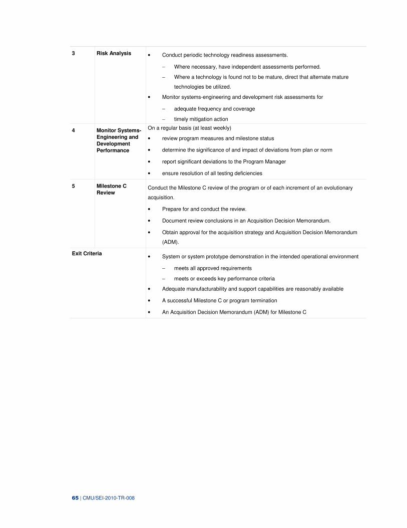
65 | CMU/SEI-2010-TR-008
3 Risk Analysis • Conduct periodic technology readiness assessments.
− Where necessary, have independent assessments performed.
− Where a technology is found not to be mature, direct that alternate mature
technologies be utilized.
• Monitor systems-engineering and development risk assessments for
− adequate frequency and coverage
− timely mitigation action
4 Monitor Systems-
Engineering and
Development
Performance
On a regular basis (at least weekly)
• review program measures and milestone status
• determine the significance of and impact of deviations from plan or norm
• report significant deviations to the Program Manager
• ensure resolution of all testing deficiencies
5 Milestone C
Review Conduct the Milestone C review of the program or of each increment of an evolutionary
acquisition.
• Prepare for and conduct the review.
• Document review conclusions in an Acquisition Decision Memorandum.
• Obtain approval for the acquisition strategy and Acquisition Decision Memorandum
(ADM).
Exit Criteria • System or system prototype demonstration in the intended operational environment
− meets all approved requirements
− meets or exceeds key performance criteria
• Adequate manufacturability and support capabilities are reasonably available
• A successful Milestone C or program termination
• An Acquisition Decision Memorandum (ADM) for Milestone C

66 | CMU/SEI-2010-TR-008
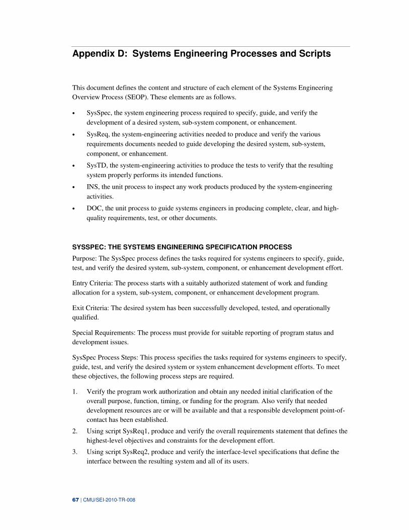
67 | CMU/SEI-2010-TR-008
Appendix D: Systems Engineering Processes and Scripts
This document defines the content and structure of each element of the Systems Engineering
Overview Process (SEOP). These elements are as follows.
• SysSpec, the system engineering process required to specify, guide, and verify the
development of a desired system, sub-system component, or enhancement.
• SysReq, the system-engineering activities needed to produce and verify the various
requirements documents needed to guide developing the desired system, sub-system,
component, or enhancement.
• SysTD, the system-engineering activities to produce the tests to verify that the resulting
system properly performs its intended functions.
• INS, the unit process to inspect any work products produced by the system-engineering
activities.
• DOC, the unit process to guide systems engineers in producing complete, clear, and high-
quality requirements, test, or other documents.
SYSSPEC: THE SYSTEMS ENGINEERING SPECIFICATION PROCESS
Purpose: The SysSpec process defines the tasks required for systems engineers to specify, guide,
test, and verify the desired system, sub-system, component, or enhancement development effort.
Entry Criteria: The process starts with a suitably authorized statement of work and funding
allocation for a system, sub-system, component, or enhancement development program.
Exit Criteria: The desired system has been successfully developed, tested, and operationally
qualified.
Special Requirements: The process must provide for suitable reporting of program status and
development issues.
SysSpec Process Steps: This process specifies the tasks required for systems engineers to specify,
guide, test, and verify the desired system or system enhancement development efforts. To meet
these objectives, the following process steps are required.
1. Verify the program work authorization and obtain any needed initial clarification of the
overall purpose, function, timing, or funding for the program. Also verify that needed
development resources are or will be available and that a responsible development point-of-
contact has been established.
2. Using script SysReq1, produce and verify the overall requirements statement that defines the
highest-level objectives and constraints for the development effort.
3. Using script SysReq2, produce and verify the interface-level specifications that define the
interface between the resulting system and all of its users.
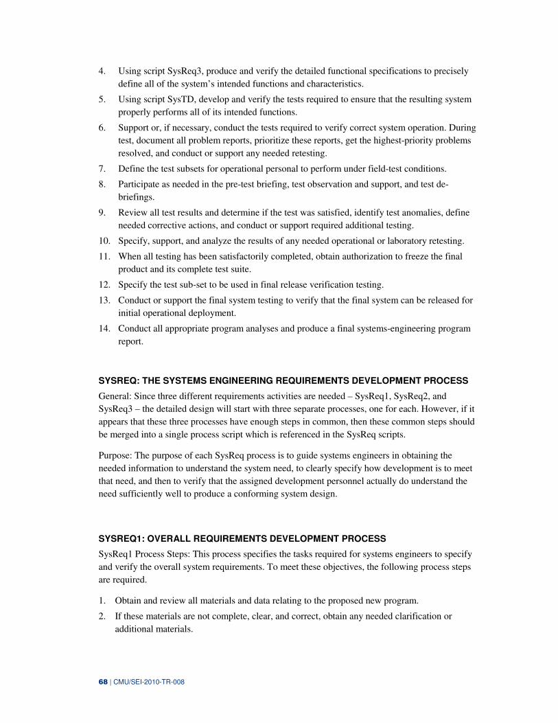
68 | CMU/SEI-2010-TR-008
4. Using script SysReq3, produce and verify the detailed functional specifications to precisely
define all of the system’s intended functions and characteristics.
5. Using script SysTD, develop and verify the tests required to ensure that the resulting system
properly performs all of its intended functions.
6. Support or, if necessary, conduct the tests required to verify correct system operation. During
test, document all problem reports, prioritize these reports, get the highest-priority problems
resolved, and conduct or support any needed retesting.
7. Define the test subsets for operational personal to perform under field-test conditions.
8. Participate as needed in the pre-test briefing, test observation and support, and test de-
briefings.
9. Review all test results and determine if the test was satisfied, identify test anomalies, define
needed corrective actions, and conduct or support required additional testing.
10. Specify, support, and analyze the results of any needed operational or laboratory retesting.
11. When all testing has been satisfactorily completed, obtain authorization to freeze the final
product and its complete test suite.
12. Specify the test sub-set to be used in final release verification testing.
13. Conduct or support the final system testing to verify that the final system can be released for
initial operational deployment.
14. Conduct all appropriate program analyses and produce a final systems-engineering program
report.
SYSREQ: THE SYSTEMS ENGINEERING REQUIREMENTS DEVELOPMENT PROCESS
General: Since three different requirements activities are needed – SysReq1, SysReq2, and
SysReq3 – the detailed design will start with three separate processes, one for each. However, if it
appears that these three processes have enough steps in common, then these common steps should
be merged into a single process script which is referenced in the SysReq scripts.
Purpose: The purpose of each SysReq process is to guide systems engineers in obtaining the
needed information to understand the system need, to clearly specify how development is to meet
that need, and then to verify that the assigned development personnel actually do understand the
need sufficiently well to produce a conforming system design.
SYSREQ1: OVERALL REQUIREMENTS DEVELOPMENT PROCESS
SysReq1 Process Steps: This process specifies the tasks required for systems engineers to specify
and verify the overall system requirements. To meet these objectives, the following process steps
are required.
1. Obtain and review all materials and data relating to the proposed new program.
2. If these materials are not complete, clear, and correct, obtain any needed clarification or
additional materials.
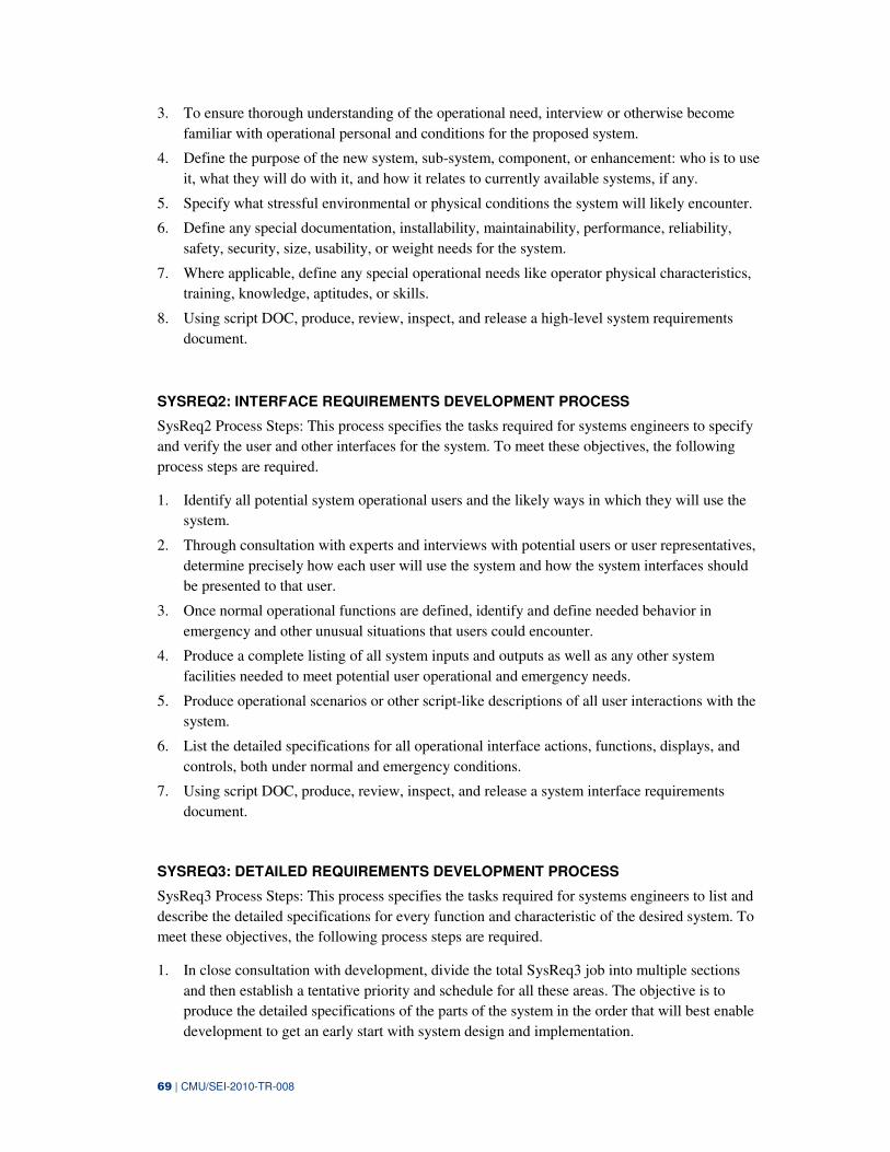
69 | CMU/SEI-2010-TR-008
3. To ensure thorough understanding of the operational need, interview or otherwise become
familiar with operational personal and conditions for the proposed system.
4. Define the purpose of the new system, sub-system, component, or enhancement: who is to use
it, what they will do with it, and how it relates to currently available systems, if any.
5. Specify what stressful environmental or physical conditions the system will likely encounter.
6. Define any special documentation, installability, maintainability, performance, reliability,
safety, security, size, usability, or weight needs for the system.
7. Where applicable, define any special operational needs like operator physical characteristics,
training, knowledge, aptitudes, or skills.
8. Using script DOC, produce, review, inspect, and release a high-level system requirements
document.
SYSREQ2: INTERFACE REQUIREMENTS DEVELOPMENT PROCESS
SysReq2 Process Steps: This process specifies the tasks required for systems engineers to specify
and verify the user and other interfaces for the system. To meet these objectives, the following
process steps are required.
1. Identify all potential system operational users and the likely ways in which they will use the
system.
2. Through consultation with experts and interviews with potential users or user representatives,
determine precisely how each user will use the system and how the system interfaces should
be presented to that user.
3. Once normal operational functions are defined, identify and define needed behavior in
emergency and other unusual situations that users could encounter.
4. Produce a complete listing of all system inputs and outputs as well as any other system
facilities needed to meet potential user operational and emergency needs.
5. Produce operational scenarios or other script-like descriptions of all user interactions with the
system.
6. List the detailed specifications for all operational interface actions, functions, displays, and
controls, both under normal and emergency conditions.
7. Using script DOC, produce, review, inspect, and release a system interface requirements
document.
SYSREQ3: DETAILED REQUIREMENTS DEVELOPMENT PROCESS
SysReq3 Process Steps: This process specifies the tasks required for systems engineers to list and
describe the detailed specifications for every function and characteristic of the desired system. To
meet these objectives, the following process steps are required.
1. In close consultation with development, divide the total SysReq3 job into multiple sections
and then establish a tentative priority and schedule for all these areas. The objective is to
produce the detailed specifications of the parts of the system in the order that will best enable
development to get an early start with system design and implementation.
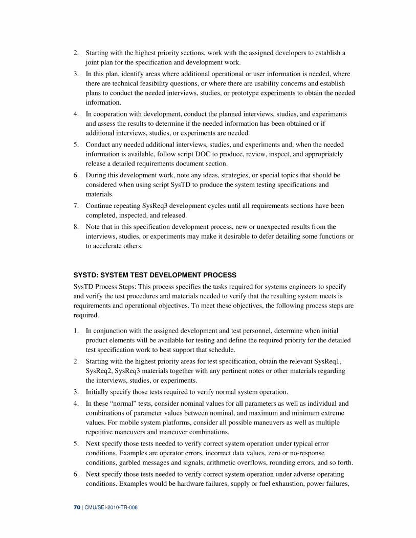
70 | CMU/SEI-2010-TR-008
2. Starting with the highest priority sections, work with the assigned developers to establish a
joint plan for the specification and development work.
3. In this plan, identify areas where additional operational or user information is needed, where
there are technical feasibility questions, or where there are usability concerns and establish
plans to conduct the needed interviews, studies, or prototype experiments to obtain the needed
information.
4. In cooperation with development, conduct the planned interviews, studies, and experiments
and assess the results to determine if the needed information has been obtained or if
additional interviews, studies, or experiments are needed.
5. Conduct any needed additional interviews, studies, and experiments and, when the needed
information is available, follow script DOC to produce, review, inspect, and appropriately
release a detailed requirements document section.
6. During this development work, note any ideas, strategies, or special topics that should be
considered when using script SysTD to produce the system testing specifications and
materials.
7. Continue repeating SysReq3 development cycles until all requirements sections have been
completed, inspected, and released.
8. Note that in this specification development process, new or unexpected results from the
interviews, studies, or experiments may make it desirable to defer detailing some functions or
to accelerate others.
SYSTD: SYSTEM TEST DEVELOPMENT PROCESS
SysTD Process Steps: This process specifies the tasks required for systems engineers to specify
and verify the test procedures and materials needed to verify that the resulting system meets is
requirements and operational objectives. To meet these objectives, the following process steps are
required.
1. In conjunction with the assigned development and test personnel, determine when initial
product elements will be available for testing and define the required priority for the detailed
test specification work to best support that schedule.
2. Starting with the highest priority areas for test specification, obtain the relevant SysReq1,
SysReq2, SysReq3 materials together with any pertinent notes or other materials regarding
the interviews, studies, or experiments.
3. Initially specify those tests required to verify normal system operation.
4. In these “normal” tests, consider nominal values for all parameters as well as individual and
combinations of parameter values between nominal, and maximum and minimum extreme
values. For mobile system platforms, consider all possible maneuvers as well as multiple
repetitive maneuvers and maneuver combinations.
5. Next specify those tests needed to verify correct system operation under typical error
conditions. Examples are operator errors, incorrect data values, zero or no-response
conditions, garbled messages and signals, arithmetic overflows, rounding errors, and so forth.
6. Next specify those tests needed to verify correct system operation under adverse operating
conditions. Examples would be hardware failures, supply or fuel exhaustion, power failures,
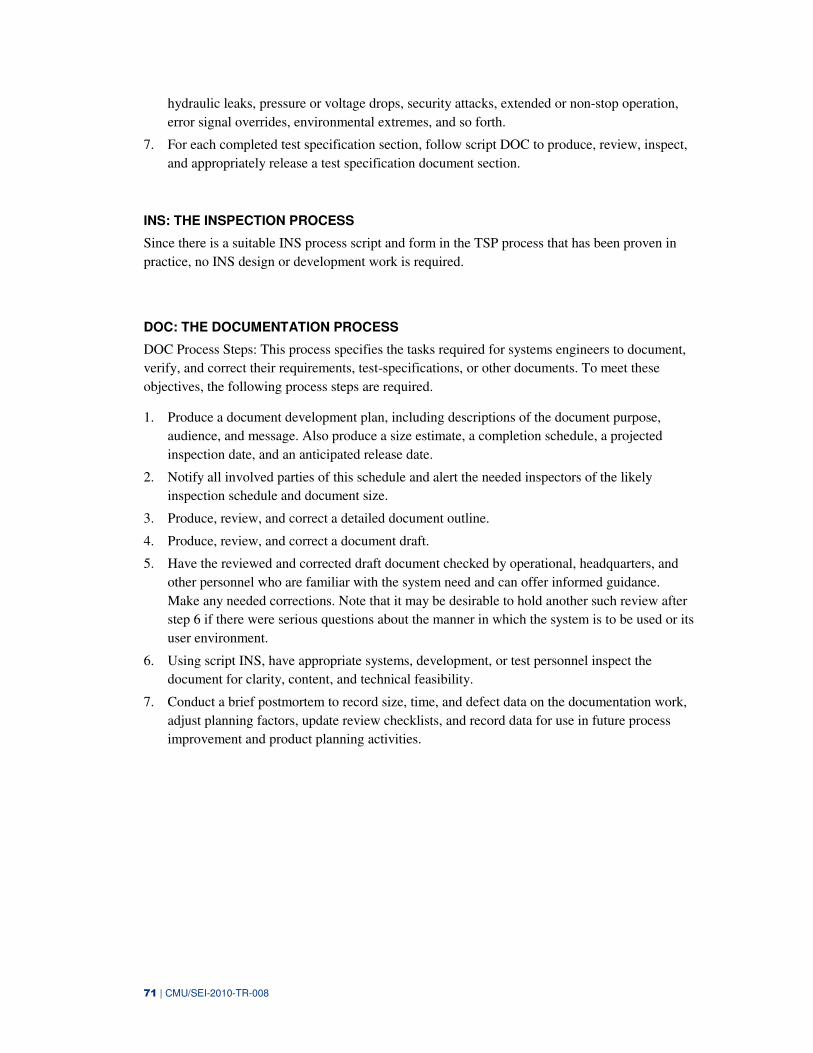
71 | CMU/SEI-2010-TR-008
hydraulic leaks, pressure or voltage drops, security attacks, extended or non-stop operation,
error signal overrides, environmental extremes, and so forth.
7. For each completed test specification section, follow script DOC to produce, review, inspect,
and appropriately release a test specification document section.
INS: THE INSPECTION PROCESS
Since there is a suitable INS process script and form in the TSP process that has been proven in
practice, no INS design or development work is required.
DOC: THE DOCUMENTATION PROCESS
DOC Process Steps: This process specifies the tasks required for systems engineers to document,
verify, and correct their requirements, test-specifications, or other documents. To meet these
objectives, the following process steps are required.
1. Produce a document development plan, including descriptions of the document purpose,
audience, and message. Also produce a size estimate, a completion schedule, a projected
inspection date, and an anticipated release date.
2. Notify all involved parties of this schedule and alert the needed inspectors of the likely
inspection schedule and document size.
3. Produce, review, and correct a detailed document outline.
4. Produce, review, and correct a document draft.
5. Have the reviewed and corrected draft document checked by operational, headquarters, and
other personnel who are familiar with the system need and can offer informed guidance.
Make any needed corrections. Note that it may be desirable to hold another such review after
step 6 if there were serious questions about the manner in which the system is to be used or its
user environment.
6. Using script INS, have appropriate systems, development, or test personnel inspect the
document for clarity, content, and technical feasibility.
7. Conduct a brief postmortem to record size, time, and defect data on the documentation work,
adjust planning factors, update review checklists, and record data for use in future process
improvement and product planning activities.
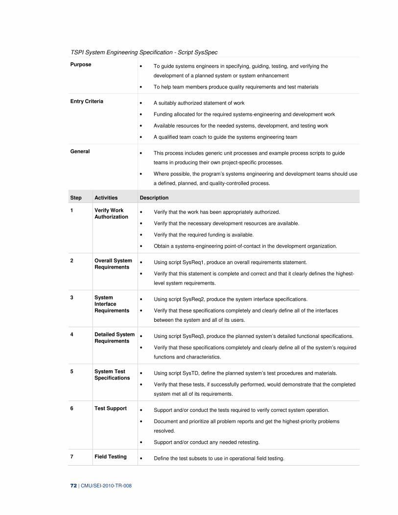
72 | CMU/SEI-2010-TR-008
TSPI System Engineering Specification - Script SysSpec
Purpose • To guide systems engineers in specifying, guiding, testing, and verifying the
development of a planned system or system enhancement
• To help team members produce quality requirements and test materials
Entry Criteria • A suitably authorized statement of work
• Funding allocated for the required systems-engineering and development work
• Available resources for the needed systems, development, and testing work
• A qualified team coach to guide the systems engineering team
General • This process includes generic unit processes and example process scripts to guide
teams in producing their own project-specific processes.
• Where possible, the program’s systems engineering and development teams should use
a defined, planned, and quality-controlled process.
Step Activities Description
1 Verify Work
Authorization • Verify that the work has been appropriately authorized.
• Verify that the necessary development resources are available.
• Verify that the required funding is available.
• Obtain a systems-engineering point-of-contact in the development organization.
2 Overall System
Requirements • Using script SysReq1, produce an overall requirements statement.
• Verify that this statement is complete and correct and that it clearly defines the highest-
level system requirements.
3 System
Interface
Requirements
• Using script SysReq2, produce the system interface specifications.
• Verify that these specifications completely and clearly define all of the interfaces
between the system and all of its users.
4 Detailed System
Requirements • Using script SysReq3, produce the planned system’s detailed functional specifications.
• Verify that these specifications completely and clearly define all of the system’s required
functions and characteristics.
5 System Test
Specifications • Using script SysTD, define the planned system’s test procedures and materials.
• Verify that these tests, if successfully performed, would demonstrate that the completed
system met all of its requirements.
6 Test Support • Support and/or conduct the tests required to verify correct system operation.
• Document and prioritize all problem reports and get the highest-priority problems
resolved.
• Support and/or conduct any needed retesting.
7 Field Testing • Define the test subsets to use in operational field testing.
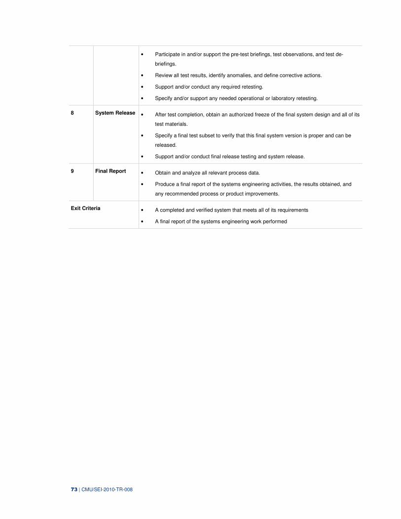
73 | CMU/SEI-2010-TR-008
• Participate in and/or support the pre-test briefings, test observations, and test de-
briefings.
• Review all test results, identify anomalies, and define corrective actions.
• Support and/or conduct any required retesting.
• Specify and/or support any needed operational or laboratory retesting.
8 System Release • After test completion, obtain an authorized freeze of the final system design and all of its
test materials.
• Specify a final test subset to verify that this final system version is proper and can be
released.
• Support and/or conduct final release testing and system release.
9 Final Report • Obtain and analyze all relevant process data.
• Produce a final report of the systems engineering activities, the results obtained, and
any recommended process or product improvements.
Exit Criteria • A completed and verified system that meets all of its requirements
• A final report of the systems engineering work performed
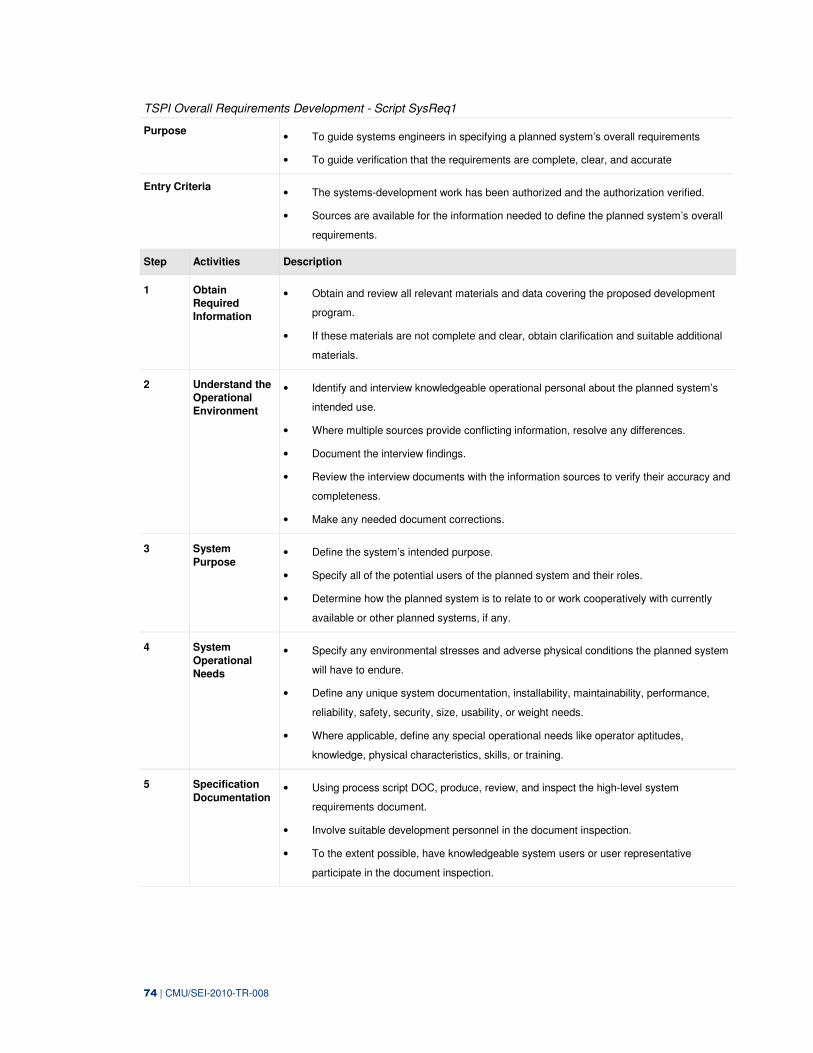
74 | CMU/SEI-2010-TR-008
TSPI Overall Requirements Development - Script SysReq1
Purpose • To guide systems engineers in specifying a planned system’s overall requirements
• To guide verification that the requirements are complete, clear, and accurate
Entry Criteria • The systems-development work has been authorized and the authorization verified.
• Sources are available for the information needed to define the planned system’s overall
requirements.
Step Activities Description
1 Obtain
Required
Information
• Obtain and review all relevant materials and data covering the proposed development
program.
• If these materials are not complete and clear, obtain clarification and suitable additional
materials.
2 Understand the
Operational
Environment
• Identify and interview knowledgeable operational personal about the planned system’s
intended use.
• Where multiple sources provide conflicting information, resolve any differences.
• Document the interview findings.
• Review the interview documents with the information sources to verify their accuracy and
completeness.
• Make any needed document corrections.
3 System
Purpose • Define the system’s intended purpose.
• Specify all of the potential users of the planned system and their roles.
• Determine how the planned system is to relate to or work cooperatively with currently
available or other planned systems, if any.
4 System
Operational
Needs
• Specify any environmental stresses and adverse physical conditions the planned system
will have to endure.
• Define any unique system documentation, installability, maintainability, performance,
reliability, safety, security, size, usability, or weight needs.
• Where applicable, define any special operational needs like operator aptitudes,
knowledge, physical characteristics, skills, or training.
5 Specification
Documentation • Using process script DOC, produce, review, and inspect the high-level system
requirements document.
• Involve suitable development personnel in the document inspection.
• To the extent possible, have knowledgeable system users or user representative
participate in the document inspection.
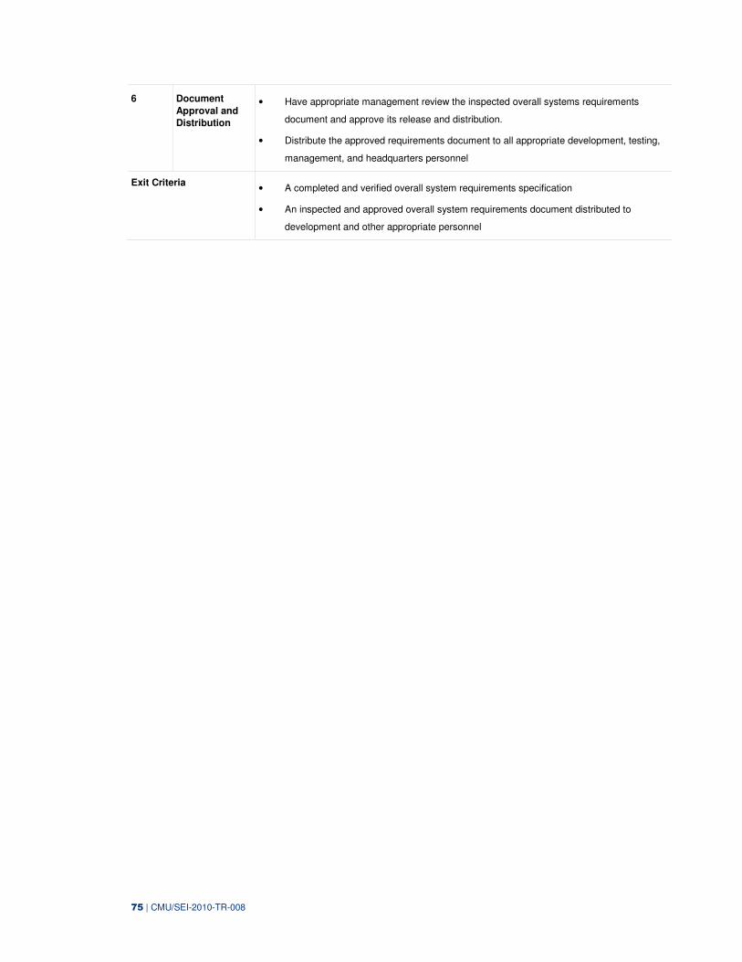
75 | CMU/SEI-2010-TR-008
6 Document
Approval and
Distribution
• Have appropriate management review the inspected overall systems requirements
document and approve its release and distribution.
• Distribute the approved requirements document to all appropriate development, testing,
management, and headquarters personnel
Exit Criteria • A completed and verified overall system requirements specification
• An inspected and approved overall system requirements document distributed to
development and other appropriate personnel
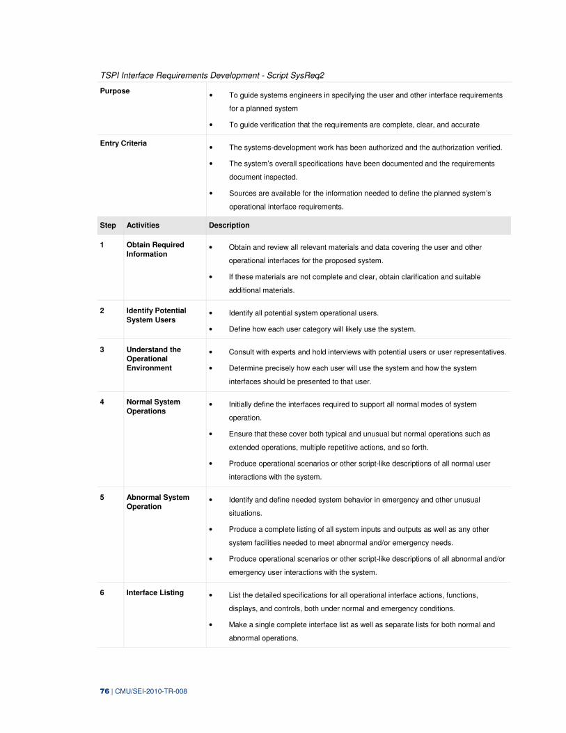
76 | CMU/SEI-2010-TR-008
TSPI Interface Requirements Development - Script SysReq2
Purpose • To guide systems engineers in specifying the user and other interface requirements
for a planned system
• To guide verification that the requirements are complete, clear, and accurate
Entry Criteria • The systems-development work has been authorized and the authorization verified.
• The system’s overall specifications have been documented and the requirements
document inspected.
• Sources are available for the information needed to define the planned system’s
operational interface requirements.
Step Activities Description
1 Obtain Required
Information • Obtain and review all relevant materials and data covering the user and other
operational interfaces for the proposed system.
• If these materials are not complete and clear, obtain clarification and suitable
additional materials.
2 Identify Potential
System Users • Identify all potential system operational users.
• Define how each user category will likely use the system.
3 Understand the
Operational
Environment
• Consult with experts and hold interviews with potential users or user representatives.
• Determine precisely how each user will use the system and how the system
interfaces should be presented to that user.
4 Normal System
Operations • Initially define the interfaces required to support all normal modes of system
operation.
• Ensure that these cover both typical and unusual but normal operations such as
extended operations, multiple repetitive actions, and so forth.
• Produce operational scenarios or other script-like descriptions of all normal user
interactions with the system.
5 Abnormal System
Operation • Identify and define needed system behavior in emergency and other unusual
situations.
• Produce a complete listing of all system inputs and outputs as well as any other
system facilities needed to meet abnormal and/or emergency needs.
• Produce operational scenarios or other script-like descriptions of all abnormal and/or
emergency user interactions with the system.
6 Interface Listing • List the detailed specifications for all operational interface actions, functions,
displays, and controls, both under normal and emergency conditions.
• Make a single complete interface list as well as separate lists for both normal and
abnormal operations.
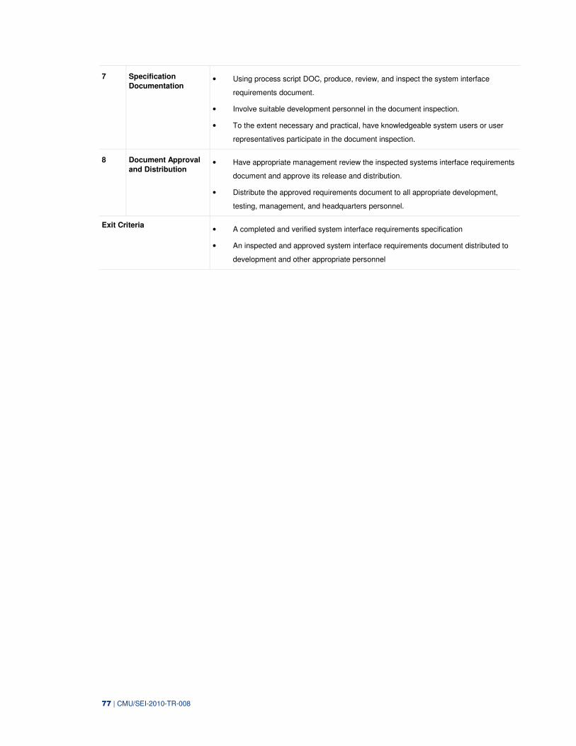
77 | CMU/SEI-2010-TR-008
7 Specification
Documentation • Using process script DOC, produce, review, and inspect the system interface
requirements document.
• Involve suitable development personnel in the document inspection.
• To the extent necessary and practical, have knowledgeable system users or user
representatives participate in the document inspection.
8 Document Approval
and Distribution • Have appropriate management review the inspected systems interface requirements
document and approve its release and distribution.
• Distribute the approved requirements document to all appropriate development,
testing, management, and headquarters personnel.
Exit Criteria • A completed and verified system interface requirements specification
• An inspected and approved system interface requirements document distributed to
development and other appropriate personnel
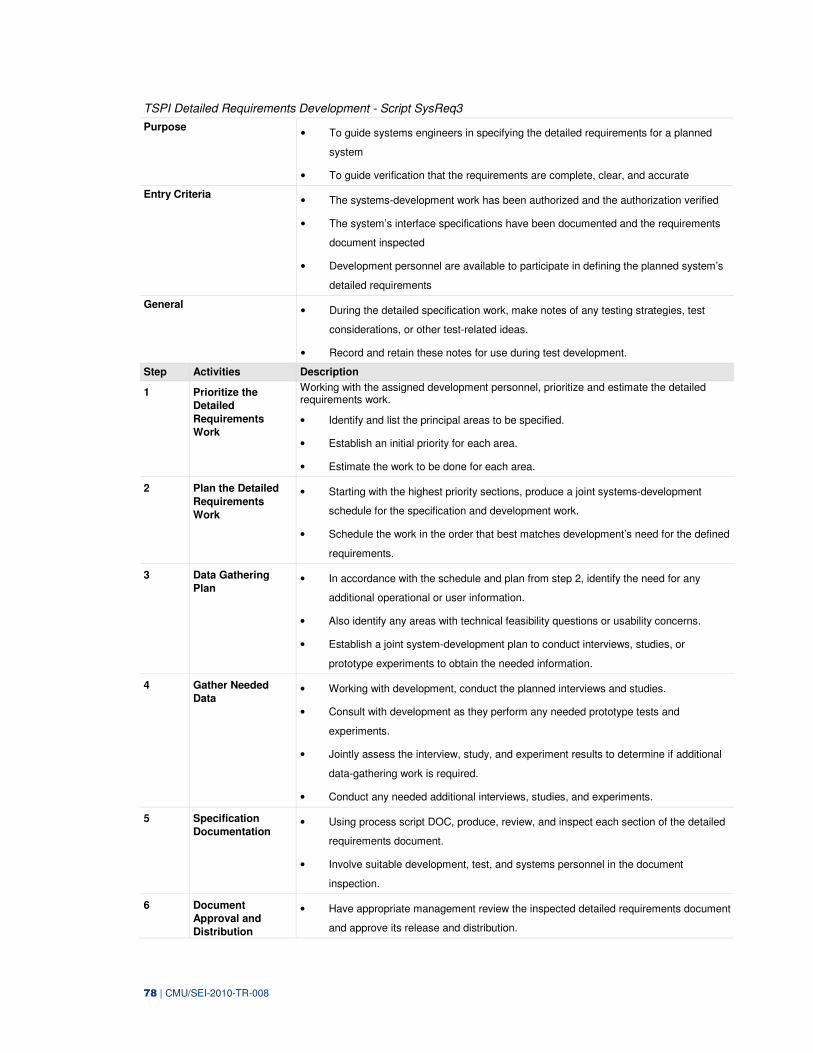
78 | CMU/SEI-2010-TR-008
TSPI Detailed Requirements Development - Script SysReq3
Purpose • To guide systems engineers in specifying the detailed requirements for a planned
system
• To guide verification that the requirements are complete, clear, and accurate
Entry Criteria • The systems-development work has been authorized and the authorization verified
• The system’s interface specifications have been documented and the requirements
document inspected
• Development personnel are available to participate in defining the planned system’s
detailed requirements
General • During the detailed specification work, make notes of any testing strategies, test
considerations, or other test-related ideas.
• Record and retain these notes for use during test development.
Step Activities Description
1 Prioritize the
Detailed
Requirements
Work
Working with the assigned development personnel, prioritize and estimate the detailed requirements work.
• Identify and list the principal areas to be specified.
• Establish an initial priority for each area.
• Estimate the work to be done for each area.
2 Plan the Detailed
Requirements
Work
• Starting with the highest priority sections, produce a joint systems-development
schedule for the specification and development work.
• Schedule the work in the order that best matches development’s need for the defined
requirements.
3 Data Gathering
Plan • In accordance with the schedule and plan from step 2, identify the need for any
additional operational or user information.
• Also identify any areas with technical feasibility questions or usability concerns.
• Establish a joint system-development plan to conduct interviews, studies, or
prototype experiments to obtain the needed information.
4 Gather Needed
Data • Working with development, conduct the planned interviews and studies.
• Consult with development as they perform any needed prototype tests and
experiments.
• Jointly assess the interview, study, and experiment results to determine if additional
data-gathering work is required.
• Conduct any needed additional interviews, studies, and experiments.
5 Specification
Documentation • Using process script DOC, produce, review, and inspect each section of the detailed
requirements document.
• Involve suitable development, test, and systems personnel in the document
inspection.
6 Document
Approval and
Distribution
• Have appropriate management review the inspected detailed requirements document
and approve its release and distribution.
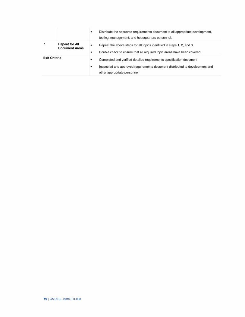
79 | CMU/SEI-2010-TR-008
• Distribute the approved requirements document to all appropriate development,
testing, management, and headquarters personnel.
7 Repeat for All
Document Areas • Repeat the above steps for all topics identified in steps 1, 2, and 3.
• Double check to ensure that all required topic areas have been covered.
Exit Criteria • Completed and verified detailed requirements specification document
• Inspected and approved requirements document distributed to development and
other appropriate personnel
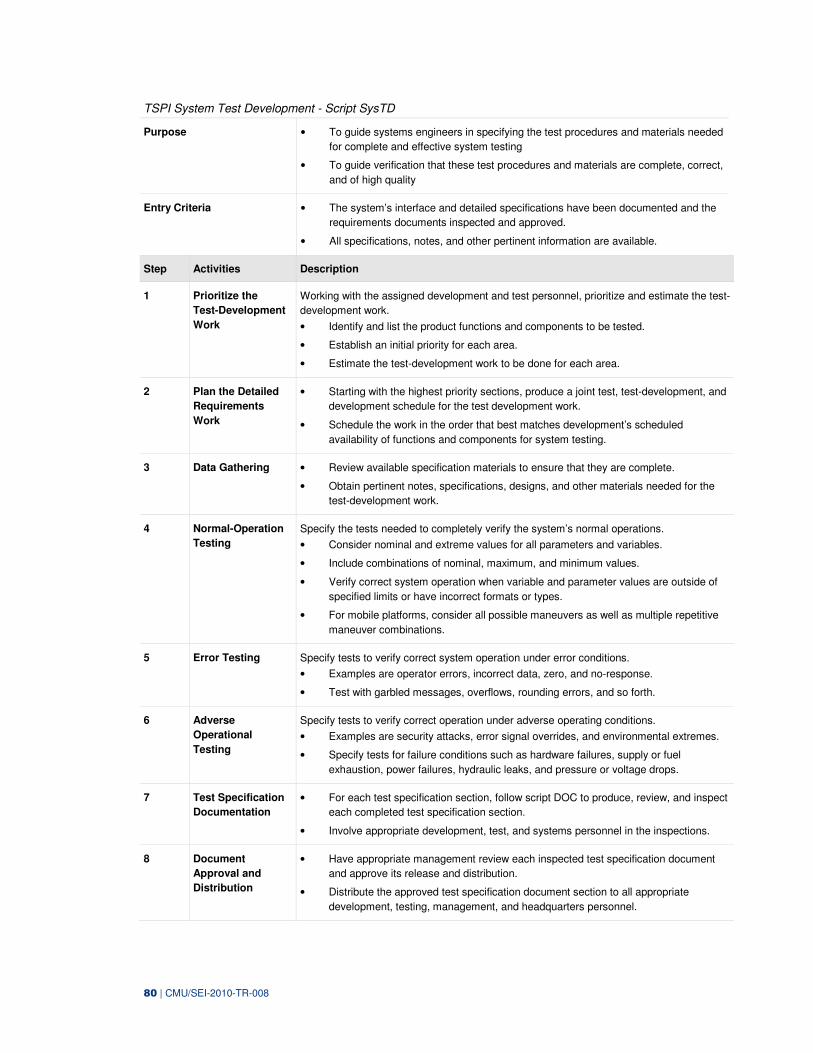
80 | CMU/SEI-2010-TR-008
TSPI System Test Development - Script SysTD
Purpose • To guide systems engineers in specifying the test procedures and materials needed
for complete and effective system testing
• To guide verification that these test procedures and materials are complete, correct,
and of high quality
Entry Criteria • The system’s interface and detailed specifications have been documented and the
requirements documents inspected and approved.
• All specifications, notes, and other pertinent information are available.
Step Activities Description
1 Prioritize the
Test-Development
Work
Working with the assigned development and test personnel, prioritize and estimate the test-
development work.
• Identify and list the product functions and components to be tested.
• Establish an initial priority for each area.
• Estimate the test-development work to be done for each area.
2 Plan the Detailed
Requirements
Work
• Starting with the highest priority sections, produce a joint test, test-development, and
development schedule for the test development work.
• Schedule the work in the order that best matches development’s scheduled
availability of functions and components for system testing.
3 Data Gathering • Review available specification materials to ensure that they are complete.
• Obtain pertinent notes, specifications, designs, and other materials needed for the
test-development work.
4 Normal-Operation
Testing
Specify the tests needed to completely verify the system’s normal operations.
• Consider nominal and extreme values for all parameters and variables.
• Include combinations of nominal, maximum, and minimum values.
• Verify correct system operation when variable and parameter values are outside of
specified limits or have incorrect formats or types.
• For mobile platforms, consider all possible maneuvers as well as multiple repetitive
maneuver combinations.
5 Error Testing Specify tests to verify correct system operation under error conditions.
• Examples are operator errors, incorrect data, zero, and no-response.
• Test with garbled messages, overflows, rounding errors, and so forth.
6 Adverse
Operational
Testing
Specify tests to verify correct operation under adverse operating conditions.
• Examples are security attacks, error signal overrides, and environmental extremes.
• Specify tests for failure conditions such as hardware failures, supply or fuel
exhaustion, power failures, hydraulic leaks, and pressure or voltage drops.
7 Test Specification
Documentation
• For each test specification section, follow script DOC to produce, review, and inspect
each completed test specification section.
• Involve appropriate development, test, and systems personnel in the inspections.
8 Document
Approval and
Distribution
• Have appropriate management review each inspected test specification document
and approve its release and distribution.
• Distribute the approved test specification document section to all appropriate
development, testing, management, and headquarters personnel.
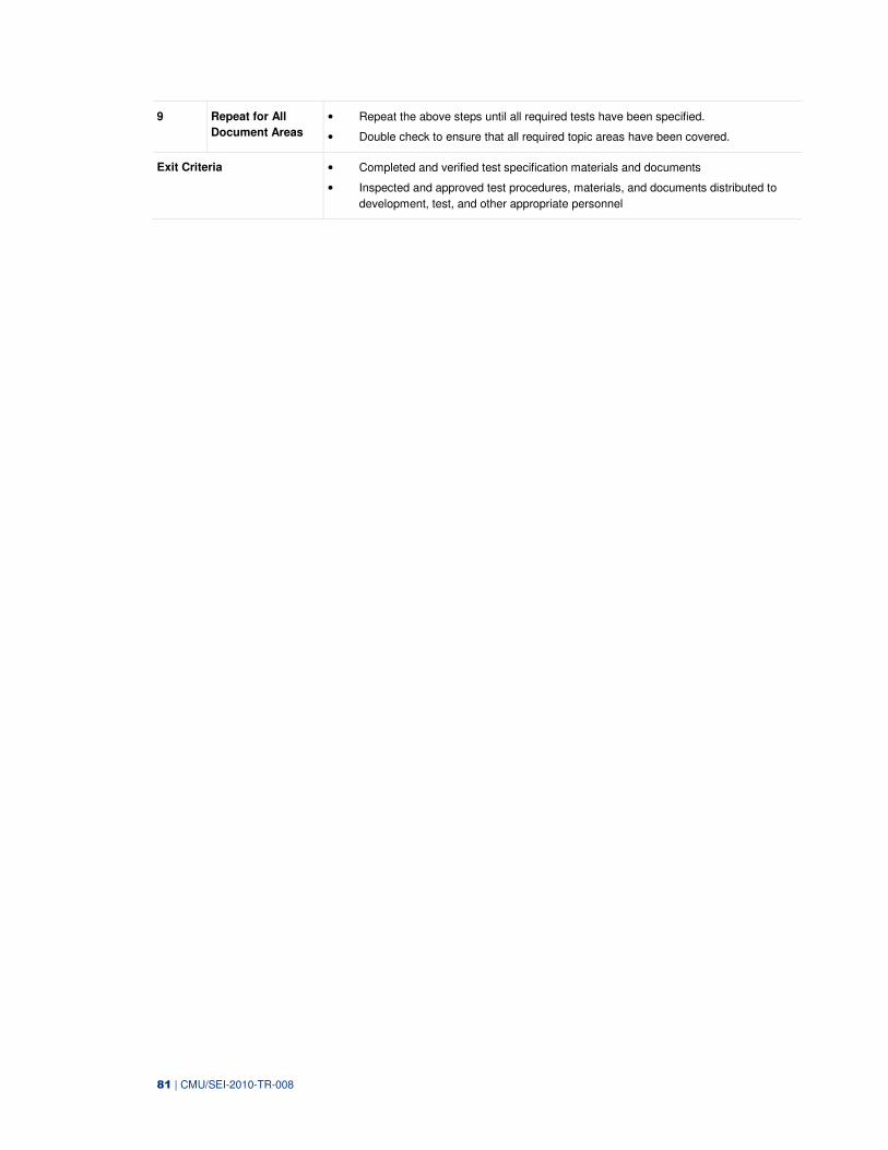
81 | CMU/SEI-2010-TR-008
9 Repeat for All
Document Areas
• Repeat the above steps until all required tests have been specified.
• Double check to ensure that all required topic areas have been covered.
Exit Criteria • Completed and verified test specification materials and documents
• Inspected and approved test procedures, materials, and documents distributed to
development, test, and other appropriate personnel
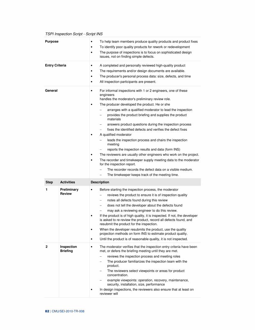
82 | CMU/SEI-2010-TR-008
TSPI Inspection Script - Script INS
Purpose • To help team members produce quality products and product fixes
• To identify poor quality products for rework or redevelopment
• The purpose of inspections is to focus on sophisticated design
issues, not on finding simple defects.
Entry Criteria • A completed and personally reviewed high-quality product
• The requirements and/or design documents are available.
• The producer's personal process data: size, defects, and time
• All inspection participants are present.
General • For informal inspections with 1 or 2 engineers, one of these
engineers
handles the moderator's preliminary review role.
• The producer developed the product. He or she
− arranges with a qualified moderator to lead the inspection
− provides the product briefing and supplies the product
materials
− answers product questions during the inspection process
− fixes the identified defects and verifies the defect fixes
• A qualified moderator
− leads the inspection process and chairs the inspection
meeting
− reports the inspection results and data (form INS)
• The reviewers are usually other engineers who work on the project.
• The recorder and timekeeper supply meeting data to the moderator
for the inspection report.
− The recorder records the defect data on a visible medium.
− The timekeeper keeps track of the meeting time.
Step Activities Description
1 Preliminary
Review
• Before starting the inspection process, the moderator
− reviews the product to ensure it is of inspection quality
− notes all defects found during this review
− does not tell the developer about the defects found
− may ask a reviewing engineer to do this review.
• If the product is of high quality, it is inspected. If not, the developer
is asked to re-review the product, record all defects found, and
resubmit the product for the inspection.
• When the developer resubmits the product, use the quality
projection methods on form INS to estimate product quality.
• Until the product is of reasonable quality, it is not inspected.
2 Inspection
Briefing
• The moderator verifies that the inspection entry criteria have been
met, or defers the briefing meeting until they are met.
− reviews the inspection process and meeting roles
− The producer familiarizes the inspection team with the
product.
− The reviewers select viewpoints or areas for product
concentration.
− example viewpoints: operation, recovery, maintenance,
security, installation, size, performance
• In design inspections, the reviewers also ensure that at least on
reviewer will
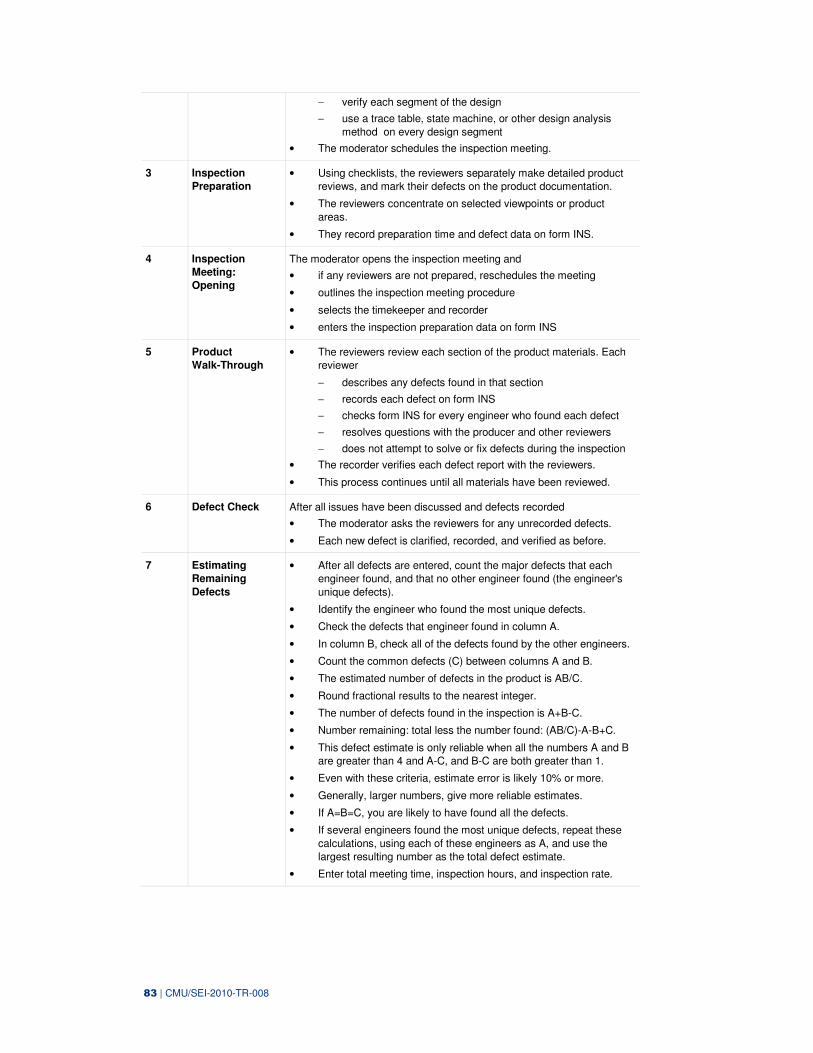
83 | CMU/SEI-2010-TR-008
− verify each segment of the design
− use a trace table, state machine, or other design analysis
method on every design segment
• The moderator schedules the inspection meeting.
3 Inspection
Preparation
• Using checklists, the reviewers separately make detailed product
reviews, and mark their defects on the product documentation.
• The reviewers concentrate on selected viewpoints or product
areas.
• They record preparation time and defect data on form INS.
4 Inspection
Meeting:
Opening
The moderator opens the inspection meeting and
• if any reviewers are not prepared, reschedules the meeting
• outlines the inspection meeting procedure
• selects the timekeeper and recorder
• enters the inspection preparation data on form INS
5 Product
Walk-Through
• The reviewers review each section of the product materials. Each
reviewer
− describes any defects found in that section
− records each defect on form INS
− checks form INS for every engineer who found each defect
− resolves questions with the producer and other reviewers
− does not attempt to solve or fix defects during the inspection
• The recorder verifies each defect report with the reviewers.
• This process continues until all materials have been reviewed.
6 Defect Check After all issues have been discussed and defects recorded
• The moderator asks the reviewers for any unrecorded defects.
• Each new defect is clarified, recorded, and verified as before.
7 Estimating
Remaining
Defects
• After all defects are entered, count the major defects that each
engineer found, and that no other engineer found (the engineer's
unique defects).
• Identify the engineer who found the most unique defects.
• Check the defects that engineer found in column A.
• In column B, check all of the defects found by the other engineers.
• Count the common defects (C) between columns A and B.
• The estimated number of defects in the product is AB/C.
• Round fractional results to the nearest integer.
• The number of defects found in the inspection is A+B-C.
• Number remaining: total less the number found: (AB/C)-A-B+C.
• This defect estimate is only reliable when all the numbers A and B
are greater than 4 and A-C, and B-C are both greater than 1.
• Even with these criteria, estimate error is likely 10% or more.
• Generally, larger numbers, give more reliable estimates.
• If A=B=C, you are likely to have found all the defects.
• If several engineers found the most unique defects, repeat these
calculations, using each of these engineers as A, and use the
largest resulting number as the total defect estimate.
• Enter total meeting time, inspection hours, and inspection rate.
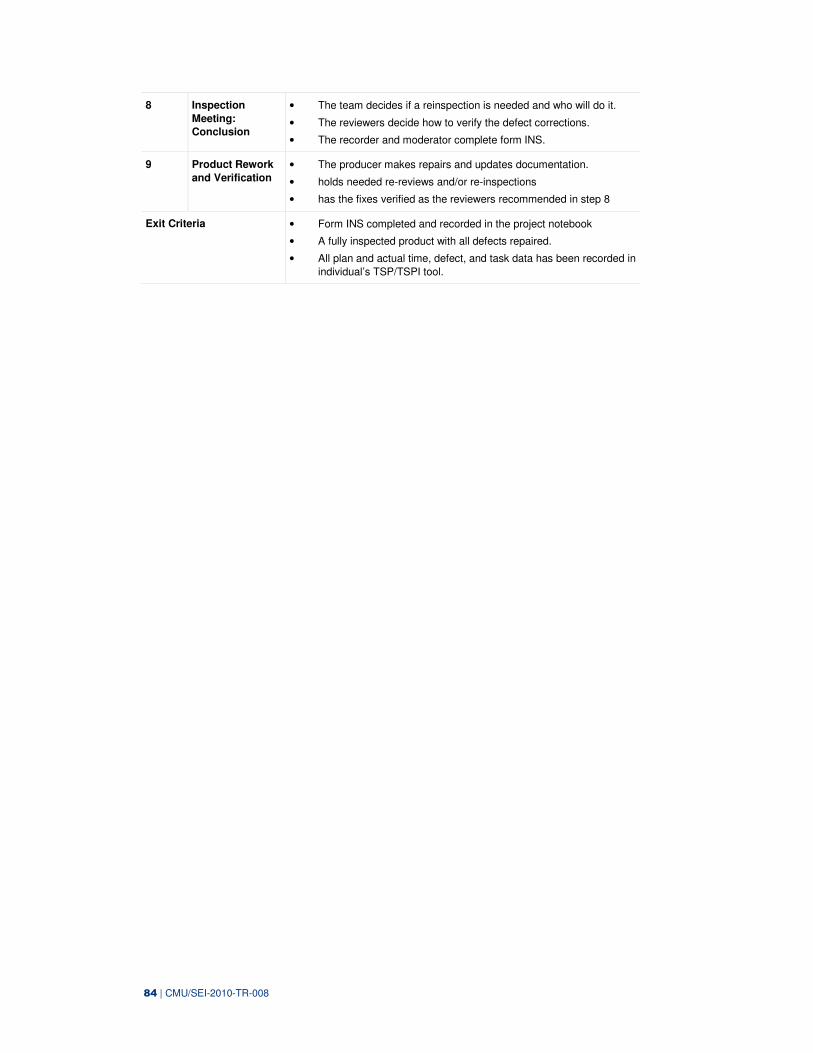
84 | CMU/SEI-2010-TR-008
8 Inspection
Meeting:
Conclusion
• The team decides if a reinspection is needed and who will do it.
• The reviewers decide how to verify the defect corrections.
• The recorder and moderator complete form INS.
9 Product Rework
and Verification
• The producer makes repairs and updates documentation.
• holds needed re-reviews and/or re-inspections
• has the fixes verified as the reviewers recommended in step 8
Exit Criteria • Form INS completed and recorded in the project notebook
• A fully inspected product with all defects repaired.
• All plan and actual time, defect, and task data has been recorded in
individual’s TSP/TSPI tool.
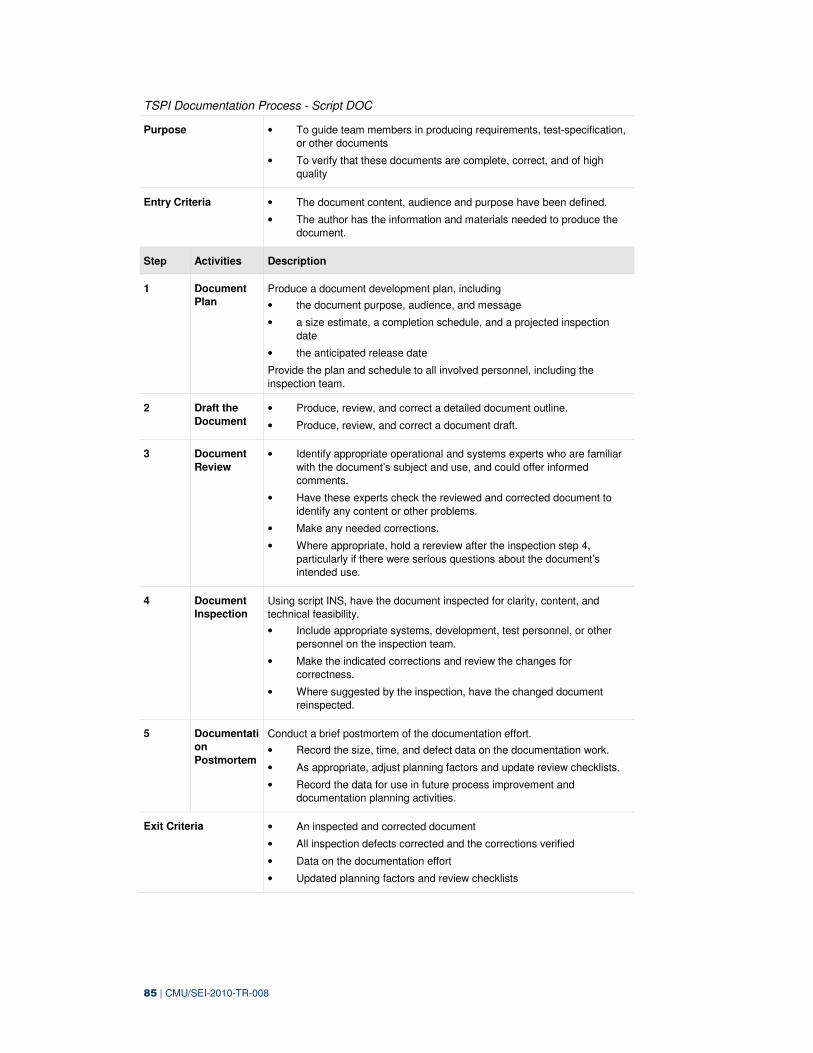
85 | CMU/SEI-2010-TR-008
TSPI Documentation Process - Script DOC
Purpose • To guide team members in producing requirements, test-specification,
or other documents
• To verify that these documents are complete, correct, and of high
quality
Entry Criteria • The document content, audience and purpose have been defined.
• The author has the information and materials needed to produce the
document.
Step Activities Description
1 Document
Plan
Produce a document development plan, including
• the document purpose, audience, and message
• a size estimate, a completion schedule, and a projected inspection
date
• the anticipated release date
Provide the plan and schedule to all involved personnel, including the
inspection team.
2 Draft the
Document
• Produce, review, and correct a detailed document outline.
• Produce, review, and correct a document draft.
3 Document
Review
• Identify appropriate operational and systems experts who are familiar
with the document’s subject and use, and could offer informed
comments.
• Have these experts check the reviewed and corrected document to
identify any content or other problems.
• Make any needed corrections.
• Where appropriate, hold a rereview after the inspection step 4,
particularly if there were serious questions about the document’s
intended use.
4 Document
Inspection
Using script INS, have the document inspected for clarity, content, and
technical feasibility.
• Include appropriate systems, development, test personnel, or other
personnel on the inspection team.
• Make the indicated corrections and review the changes for
correctness.
• Where suggested by the inspection, have the changed document
reinspected.
5 Documentati
on
Postmortem
Conduct a brief postmortem of the documentation effort.
• Record the size, time, and defect data on the documentation work.
• As appropriate, adjust planning factors and update review checklists.
• Record the data for use in future process improvement and
documentation planning activities.
Exit Criteria • An inspected and corrected document
• All inspection defects corrected and the corrections verified
• Data on the documentation effort
• Updated planning factors and review checklists

86 | CMU/SEI-2010-TR-008
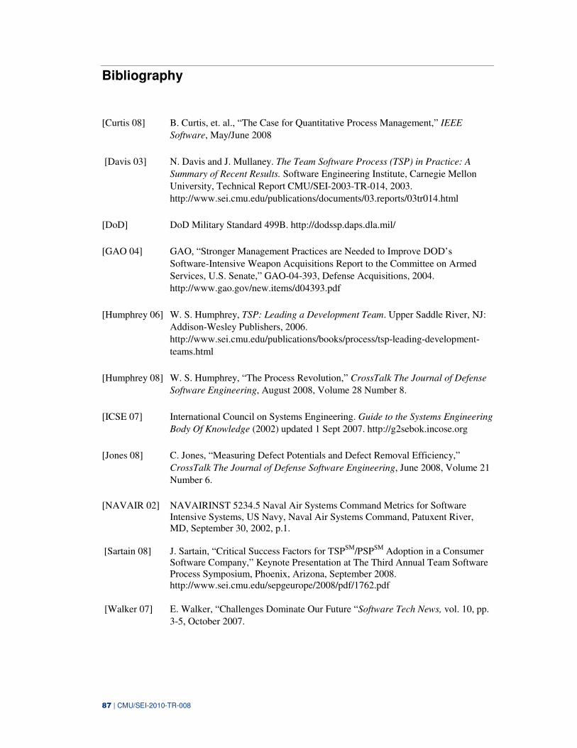
87 | CMU/SEI-2010-TR-008
Bibliography
[Curtis 08] B. Curtis, et. al., “The Case for Quantitative Process Management,” IEEE
Software, May/June 2008
[Davis 03] N. Davis and J. Mullaney. The Team Software Process (TSP) in Practice: A
Summary of Recent Results. Software Engineering Institute, Carnegie Mellon
University, Technical Report CMU/SEI-2003-TR-014, 2003.
http://www.sei.cmu.edu/publications/documents/03.reports/03tr014.html
[DoD] DoD Military Standard 499B. http://dodssp.daps.dla.mil/
[GAO 04] GAO, “Stronger Management Practices are Needed to Improve DOD’s
Software-Intensive Weapon Acquisitions Report to the Committee on Armed
Services, U.S. Senate,” GAO-04-393, Defense Acquisitions, 2004.
http://www.gao.gov/new.items/d04393.pdf
[Humphrey 06] W. S. Humphrey, TSP: Leading a Development Team. Upper Saddle River, NJ:
Addison-Wesley Publishers, 2006.
http://www.sei.cmu.edu/publications/books/process/tsp-leading-development-
teams.html
[Humphrey 08] W. S. Humphrey, “The Process Revolution,” CrossTalk The Journal of Defense
Software Engineering, August 2008, Volume 28 Number 8.
[ICSE 07] International Council on Systems Engineering. Guide to the Systems Engineering
Body Of Knowledge (2002) updated 1 Sept 2007. http://g2sebok.incose.org
[Jones 08] C. Jones, “Measuring Defect Potentials and Defect Removal Efficiency,”
CrossTalk The Journal of Defense Software Engineering, June 2008, Volume 21
Number 6.
[NAVAIR 02] NAVAIRINST 5234.5 Naval Air Systems Command Metrics for Software Intensive Systems, US Navy, Naval Air Systems Command, Patuxent River, MD, September 30, 2002, p.1.
[Sartain 08] J. Sartain, “Critical Success Factors for TSP
SM/PSP
SM Adoption in a Consumer
Software Company,” Keynote Presentation at The Third Annual Team Software Process Symposium, Phoenix, Arizona, September 2008. http://www.sei.cmu.edu/sepgeurope/2008/pdf/1762.pdf
[Walker 07] E. Walker, “Challenges Dominate Our Future “Software Tech News, vol. 10, pp.
3-5, October 2007.
88 | CMU/SEI-2010-TR-008
[Wall 05] D. S. Wall, J. McHale, and M. Pomeroy-Huff. Case Study: Accelerating Process
Improvement by Integrating the TSP and CMMI. Software Engineering Institute,
Carnegie Mellon University, Special Report CMU/SEI-2005-SR-012, 2005.
http://www.sei.cmu.edu/publications/documents/05.reports/05sr012.html
[Weinberg 08] G. M. Weinberg, “What Have 20 Years Accomplished and What Is Left to
Accomplish in the Next 20 Years?” CrossTalk The Journal of Defense Software
Engineering, August 2008, Volume 28 Number 8.
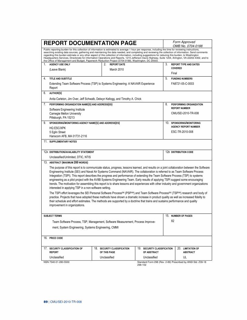
89 | CMU/SEI-2010-TR-008
REPORT DOCUMENTATION PAGE Form Approved
OMB No. 0704-0188 Public reporting burden for this collection of information is estimated to average 1 hour per response, including the time for reviewing instructions, searching existing data sources, gathering and maintaining the data needed, and completing and reviewing the collection of information. Send comments regarding this burden estimate or any other aspect of this collection of information, including suggestions for reducing this burden, to Washington Headquarters Services, Directorate for information Operations and Reports, 1215 Jefferson Davis Highway, Suite 1204, Arlington, VA 22202-4302, and to the Office of Management and Budget, Paperwork Reduction Project (0704-0188), Washington, DC 20503.
1. AGENCY USE ONLY
(Leave Blank)
2. REPORT DATE
March 2010
3. REPORT TYPE AND DATES
COVERED
Final
4. TITLE AND SUBTITLE
Extending Team Software Process (TSP) to Systems Engineering: A NAVAIR Experience
Report
5. FUNDING NUMBERS
FA8721-05-C-0003
6. AUTHOR(S)
Anita Carleton, Jim Over, Jeff Schwalb, Delwyn Kellogg, and Timothy A. Chick
7. PERFORMING ORGANIZATION NAME(S) AND ADDRESS(ES)
Software Engineering Institute
Carnegie Mellon University
Pittsburgh, PA 15213
8. PERFORMING ORGANIZATION REPORT NUMBER
CMU/SEI-2010-TR-008
9. SPONSORING/MONITORING AGENCY NAME(S) AND ADDRESS(ES)
HQ ESC/XPK
5 Eglin Street
Hanscom AFB, MA 01731-2116
10. SPONSORING/MONITORING
AGENCY REPORT NUMBER
ESC-TR-2010-008
11. SUPPLEMENTARY NOTES
12A DISTRIBUTION/AVAILABILITY STATEMENT
Unclassified/Unlimited, DTIC, NTIS
12B DISTRIBUTION CODE
13. ABSTRACT (MAXIMUM 200 WORDS)
The purpose of this report is to communicate status, progress, lessons learned, and results on a joint collaboration between the Software
Engineering Institute (SEI) and Naval Air Systems Command (NAVAIR). The collaboration is referred to as Team Software Process
Integration (TSPI). This report describes the progress and performance of extending the Team Software Process (TSP) to systems
engineering as a pilot project with the AV8B Systems Engineering Team. Early results of applying TSPI suggest some encouraging
trends. The motivation for assembling this report is to share lessons and experiences with other industry and government organizations
interested in applying TSP in a non-software setting.
The TSPI effort leverages the SEI Personal Software ProcessSM (PSPSM) and Team Software ProcessSM (TSPSM) research and body of
practice. Projects that have adopted these methods have shown a dramatic increase in product quality as well as increased fidelity to
their schedule and effort estimates. The methods are supported by a doctrine that trains and sustains performance and quality
improvement in organizations.
SUBJECT TERMS
Team Software Process, TSP, Management, Software Measurement, Process Improve-
ment, System Engineering, Systems Engineering, CMMI
15. NUMBER OF PAGES
82
16. PRICE CODE
17. SECURITY CLASSIFICATION OF
REPORT
Unclassified
18. SECURITY CLASSIFICATION
OF THIS PAGE
Unclassified
19. SECURITY CLASSIFICATION
OF ABSTRACT
Unclassified
20. LIMITATION OF
ABSTRACT
UL
NSN 7540-01-280-5500 Standard Form 298 (Rev. 2-89) Prescribed by ANSI Std. Z39-18 298-102