Embed Size (px)
Citation preview
Altech Corp.® • 35 Royal Road • Flemington, NJ 08822-6000 • Phone (908)806-9400 • FAX (908)806-9490 • www.altechcorp.com4
Catalog NumberNo. of PolesGeneral Purpose CurrentMaximum VoltageMotor FLA @ 480V ACMotor FLA @ 600V AC
Horsepower Rating/HP110-120V AC200V AC208V AC220-240V AC265V AC277V AC380-415V AC440-480V AC550-600V AC
Short Circuit WithstandRating at 600 V with Max. Fuse Size/Class:
K5RK5RK1J
Terminal SizeAcceptability(Cu Conductors only, 75 °C)Terminal TorqueScrew Head Type
Dimensions(to convert to inches multiply by 0.03937)
Weight
Suitable AccessoriesExtended Handle Applications(Door Interlock Mechanism)
ShaftHandlesAuxiliary SwitchFuse Holder
Direct Handle ApplicationsHandle for 3 PoleHandle for 4 PoleDoor Mounting Kits
KU316N3 (4 pole - KU416N)
16 A600V AC
14 A9 A
1 Phase 3 Phase1 2
1.5 31.5 32 3– 5– 5– 7.5– 10– 7.5
10 kA
30 A30 A60 A80 A
14-8 AWG
16 lb. in. (1.8 Nm)No. 2 Pozidrive
0.172 kg (0.379 lb.) (3 pole)0.215 kg (0.474 lb.) (4 pole)
L(1,2,3)00AD11-STLK10 (Y/R) UL, LK11 (Y/R) U
KU1.V, KU2.V—
K/KU3P (Y/R)K/KU4P (Y/R)
OKA/KU LK10 x; OKA x
KU325N3 (4 pole - KU425N)
25 A600V AC
21 A11 A
1 Phase 3 Phase1.5 32 52 53 5– 7.5– 7.5– 10– 15– 10
10 kA
30 A30 A60 A80 A
14-8 AWG
16 lb. in. (1.8 Nm)No. 2 Pozidrive
0.172 kg (0.379 lb.) (3 pole)0.215 kg (0.474 lb.) (4 pole)
L(1,2,3)00AD11-STLK10 (Y/R) UL, LK11 (Y/R) U
KU1.V, KU2.V—
K/KU3P (Y/R)K/KU4P (Y/R)
OKA/KU LK10 x; OKA x
KU340N3 (4 pole - KU440N)
40 A600V AC
27 A17 A
1 Phase 3 Phase2 33 7.53 7.55 7.5– 10– 10– 15– 20– 15
10 kA
30 A30 A60 A80 A
14-8 AWG
16 lb. in. (1.8 Nm)No. 2 Pozidrive
0.172 kg (0.379 lb.) (3 pole)0.215 kg (0.474 lb.) (4 pole)
L(1,2,3)00AD11-STLK10 (Y/R) UL, LK11 (Y/R) U
KU1.V, KU2.VKV 10x38, KV 10x38 CC
K/KU3P (Y/R)K/KU4P (Y/R)
OKA/KU LK10 x; OKA x
KU363N3 (4 pole - KU463N)
60 A600V AC
34 A27 A
1 Phase 3 Phase3 55 105 10
7.5 10– 10– 10– 20– 25– 25
10 kA
30 A30 A60 A
100 A
12-4 AWG
16 lb. in. (1.8 Nm)No. 2 Pozidrive
0.200 kg (0.441 lb.) (3 pole)0.245 kg (0.540 lb.) (4 pole)
L(1,2,3)00AD11-STLK10 (Y/R) UL, LK11 (Y/R) U
KU1.V, KU2.V—
K/KU3P (Y/R)K/KU4P (Y/R)
OKA/KU LK10 x; OKA x
KU380N3 (4 pole - KU480N)
80 A600V AC
40 A32 A
1 Phase 3 Phase5 7.5
7.5 107.5 1010 15– 15– 15– 25– 30– 30
10 kA
30 A30 A60 A
100 A
12-4 AWG
16 lb. in. (1.8 Nm)No. 2 Pozidrive
0.200 kg (0.441 lb.) (3 pole)0.245 kg (0.540 lb.) (4 pole)
L(1,2,3)00AD11-STLK10 (Y/R) UL, LK11 (Y/R) U
KU1.V, KU2.V—
K/KU3P (Y/R)K/KU4P (Y/R)
OKA/KU LK10 x; OKA x
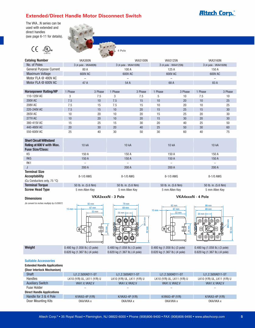
The KU...N series can beused with extended anddirect handles(see page 6-11 for details).
Extended/Direct Handle Motor Disconnect Switch
E1851154 Pole NEW
35 m
m
74 m
m
66 m
m
58 mm15 mm15.8mm
15.8mm
73 mm 49.5 mm
35 m
m
66 m
m
74 m
m
73 mm 65 mm
15.8mm15 mm
15.8mm
15.8mm58 mm
KU3xxN - 3 Pole KU4xxN - 4 Pole
Altech Corp.® • 35 Royal Road • Flemington, NJ 08822-6000 • Phone (908)806-9400 • FAX (908)806-9490 • www.altechcorp.com 5
Catalog NumberNo. of PolesGeneral Purpose CurrentMaximum VoltageMotor FLA @ 480V ACMotor FLA @ 600V AC
Horsepower Rating/HP110-120V AC200V AC208V AC220-240V AC265V AC277V AC380-415V AC440-480V AC550-600V AC
Short Circuit WithstandRating at 600 V with Max. Fuse Size/Class:
K5RK5RK1J
Terminal SizeAcceptability(Cu Conductors only, 75 °C)Terminal TorqueScrew Head Type
Dimensions(to convert to inches multiply by 0.03937)
Weight
Suitable AccessoriesExtended Handle Applications(Door Interlock Mechanism)
ShaftHandlesAuxiliary SwitchFuse Holder
Direct Handle ApplicationsHandle for 3 & 4 PoleDoor Mounting Kits
VKA380N3 (4 pole - VKA480N)
80 A600V AC
–47 A
1 Phase 3 Phase3 7.5
7.5 107.5 157.5 1510 2010 2015 2520 3025 40
10 kA
150 A150 A
–200 A
8-1/0 AWG
50 lb. in. (5.6 Nm)5 mm Allen Key
0.480 kg (1.058 lb.) (3 pole)0.620 kg (1.367 lb.) (4 pole)
L(1,2.3)00AD11-STLK10 (Y/R) UL, LK11 (Y/R) U
VKA1.V, VKA2.V–
K/VKA3-4P (Y/R)OKA/VKA x
VKA3100N3 (4 pole - VKA4100N)
100 A600V AC
–54 A
1 Phase 3 Phase3 7.5
7.5 157.5 1510 2010 2010 2015 3020 4030 50
10 kA
150 A150 A
–200 A
8-1/0 AWG
50 lb. in. (5.6 Nm)5 mm Allen Key
0.480 kg (1.058 lb.) (3 pole)0.620 kg (1.367 lb.) (4 pole)
L(1,2.3)00AD11-STLK10 (Y/R) UL, LK11 (Y/R) U
VKA1.V, VKA2.V–
K/VKA3-4P (Y/R)OKA/VKA x
VKA3125N3 (4 pole - VKA4125N)
125 A600V AC
–68 A
1 Phase 3 Phase5 10
10 2010 2015 2515 2515 3020 4025 5030 60
10 kA
150 A150 A
–200 A
8-1/0 AWG
50 lb. in. (5.6 Nm)5 mm Allen Key
0.480 kg (1.058 lb.) (3 pole)0.620 kg (1.367 lb.) (4 pole)
L(1,2.3)00AD11-STLK10 (Y/R) UL, LK11 (Y/R) U
VKA1.V, VKA2.V–
K/VKA3-4P (Y/R)OKA/VKA x
VKA3160N3 (4 pole - VKA4160N)
150 A600V AC
–83 A
1 Phase 3 Phase7.5 1010 2510 2515 3020 3020 3025 5030 6040 75
10 kA
150 A150 A
–200 A
8-1/0 AWG
50 lb. in. (5.6 Nm)5 mm Allen Key
0.480 kg (1.058 lb.) (3 pole)0.620 kg (1.367 lb.) (4 pole)
L(1,2.3)00AD11-STLK10 (Y/R) UL, LK11 (Y/R) U
VKA1.V, VKA2.V–
K/VKA3-4P (Y/R)OKA/VKA x
The VKA...N series can beused with extended anddirect handles(see page 6-11 for details).
Extended/Direct Handle Motor Disconnect Switch
E1851154 Pole
82 mm
15 mm
82 m
m
79 mm
69 mm
20 mm
67 mm
53 mm
35 m
m
2
1
6
3 5 Ø4.5
mm
82 m
m
82 mm
89 mm
99 mm
20 mm
4
67 mm
53 mm15 mm
35 m
m
2
1 3
6 8
75
Ø4.5
mm
VKA3xxxN - 3 Pole VKA4xxxN - 4 Pole
Ø79
mm
Ø22.5 mm
Panel Drilling:
3 mm
12.7
mm
38 m
m12
mm
41 m
m4
mm
Ø40 mm
63 mm
Ø78.
5 m
m
28.2
mm
28.2mm
Ø22.5 mm Ø4 mm
DrillTemplateIncluded
DrillTemplateIncluded
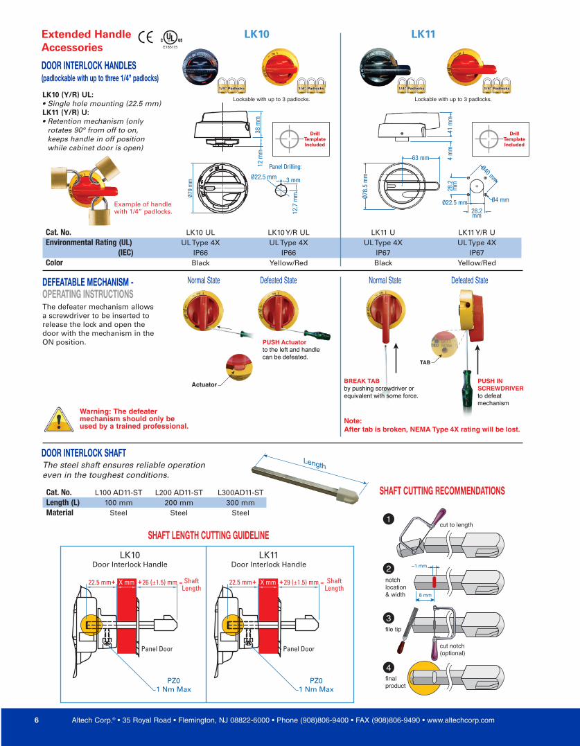
BREAK TABby pushing screwdriver orequivalent with some force.
PUSH INSCREWDRIVERto defeatmechanism
Note:After tab is broken, NEMA Type 4X rating will be lost.
PUSH Actuatorto the left and handlecan be defeated.
TAB
Actuator
X mm
22.5 mm X mm 26 (±1.5) mm = 29 (±1.5) mm =
PZ01 Nm Max
PZ01 Nm Max
LK10Door Interlock Handle
LK11Door Interlock Handle
22.5 mm
Panel Door Panel Door
ShaftLength
+ + + + ShaftLength
1/4” Padlocks1/4” Padlocks1/4” Padlocks 1/4” Padlocks1/4” Padlocks1/4” Padlocks 1/4” Padlocks1/4” Padlocks1/4” Padlocks 1/4” Padlocks1/4” Padlocks1/4” Padlocks
Example of handlewith 1/4” padlocks.
Warning: The defeatermechanism should only beused by a trained professional.
Altech Corp.® • 35 Royal Road • Flemington, NJ 08822-6000 • Phone (908)806-9400 • FAX (908)806-9490 • www.altechcorp.com6
Length
Cat. No. LK10 UL LK10 Y/R UL LK11 U LK11 Y/R UEnvironmental Rating (UL) UL Type 4X UL Type 4X UL Type 4X UL Type 4X
(IEC) IP66 IP66 IP67 IP67Color Black Yellow/Red Black Yellow/Red
Cat. No. L100 AD11-ST L200 AD11-ST L300AD11-STLength (L) 100 mm 200 mm 300 mmMaterial Steel Steel Steel
The steel shaft ensures reliable operationeven in the toughest conditions.
DOOR INTERLOCK SHAFT
Extended HandleAccessories
LK10 LK11
DOOR INTERLOCK HANDLES(padlockable with up to three 1/4” padlocks)
LK10 (Y/R) UL:• Single hole mounting (22.5 mm)LK11 (Y/R) U:• Retention mechanism (only rotates 90° from off to on, keeps handle in off position while cabinet door is open)
The defeater mechanism allowsa screwdriver to be inserted torelease the lock and open thedoor with the mechanism in theON position.
E185115
SHAFT CUTTING RECOMMENDATIONS
SHAFT LENGTH CUTTING GUIDELINE
Lockable with up to 3 padlocks. Lockable with up to 3 padlocks.
DEFEATABLE MECHANISM - OPERATING INSTRUCTIONS
Normal State Defeated State Normal State Defeated State
cut to length
cut notch(optional)
file tip
finalproduct
8 mm
~1 mm
notchlocation& width
1
2
3
4
Kit shown; comes withswitch and fuse holder.
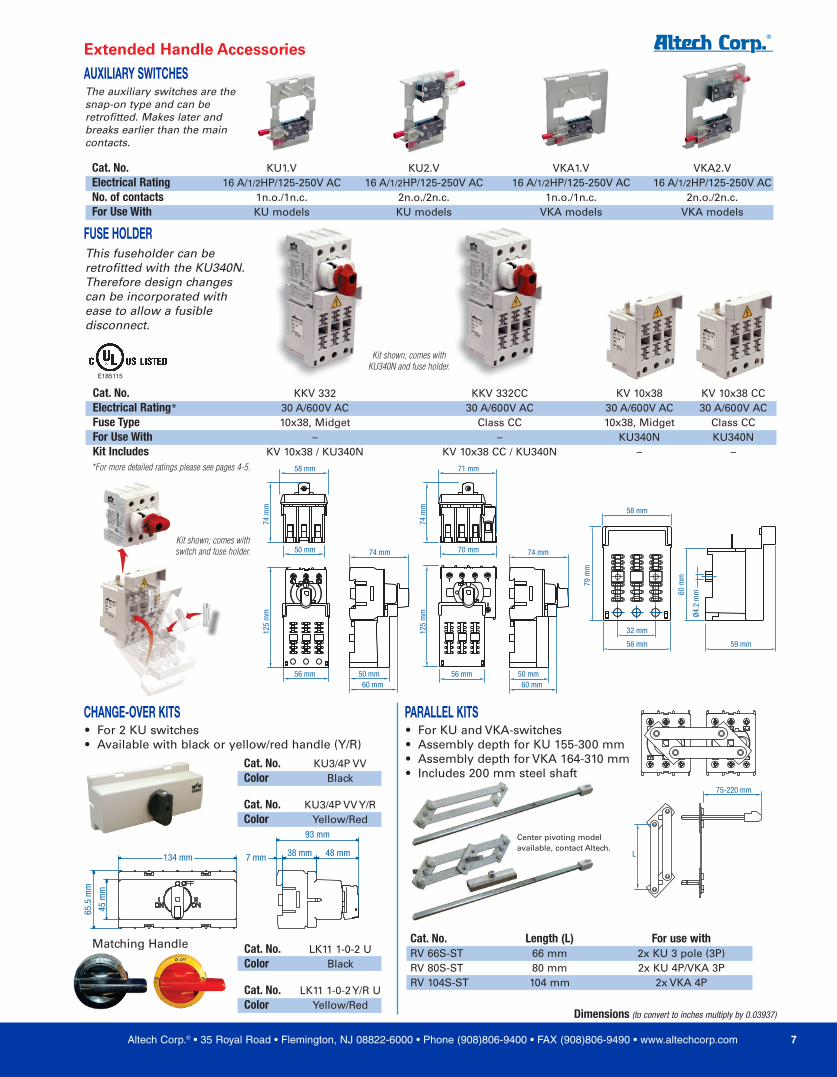
*For more detailed ratings please see pages 4-5.
Kit shown; comes withKU340N and fuse holder.
FUSE HOLDER
58 mm
50 mm 70 mm
71 mm
74 mm 74 mm
56 mm 56 mm50 mm60 mm
50 mm60 mm
74 m
m
74 m
m
125
mm
125
mm
79 m
m
60 m
m
59 mm
Ø4.2
mm
32 mm
56 mm
58 mm
This fuseholder can beretrofitted with the KU340N.Therefore design changescan be incorporated withease to allow a fusibledisconnect.
E185115
Cat. No. KKV 332 KKV 332CC KV 10x38 KV 10x38 CCElectrical Rating* 30 A/600V AC 30 A/600V AC 30 A/600V AC 30 A/600V ACFuse Type 10x38, Midget Class CC 10x38, Midget Class CCFor Use With – – KU340N KU340NKit Includes KV 10x38 / KU340N KV 10x38 CC / KU340N – –
Altech Corp.® • 35 Royal Road • Flemington, NJ 08822-6000 • Phone (908)806-9400 • FAX (908)806-9490 • www.altechcorp.com 7
75-220 mm
L
93 mm
65.5
mm
134 mm 7 mm 38 mm 48 mm
45 m
m
Extended Handle Accessories
Cat. No. KU1.V KU2.V VKA1.V VKA2.VElectrical Rating 16 A/1/2HP/125-250V AC 16 A/1/2HP/125-250V AC 16 A/1/2HP/125-250V AC 16 A/1/2HP/125-250V ACNo. of contacts 1n.o./1n.c. 2n.o./2n.c. 1n.o./1n.c. 2n.o./2n.c.For Use With KU models KU models VKA models VKA models
Cat. No. KU3/4P VVColor Black
Cat. No. KU3/4P VV Y/RColor Yellow/Red
Cat. No. LK11 1-0-2 UColor Black
Cat. No. LK11 1-0-2 Y/R UColor Yellow/Red
Cat. No. Length (L) For use withRV 66S-ST 66 mm 2x KU 3 pole (3P)RV 80S-ST 80 mm 2x KU 4P/VKA 3PRV 104S-ST 104 mm 2x VKA 4P
AUXILIARY SWITCHESThe auxiliary switches are thesnap-on type and can beretrofitted. Makes later andbreaks earlier than the maincontacts.
Dimensions (to convert to inches multiply by 0.03937)
CHANGE-OVER KITS• For 2 KU switches• Available with black or yellow/red handle (Y/R)
PARALLEL KITS• For KU and VKA-switches• Assembly depth for KU 155-300 mm• Assembly depth for VKA 164-310 mm• Includes 200 mm steel shaft
Center pivoting modelavailable, contact Altech.
Matching Handle
Altech Corp.® • 35 Royal Road • Flemington, NJ 08822-6000 • Phone (908)806-9400 • FAX (908)806-9490 • www.altechcorp.com8
52 mm
74 m
m
45 m
m
66 m
m
45 mm 36 mm
81 mm
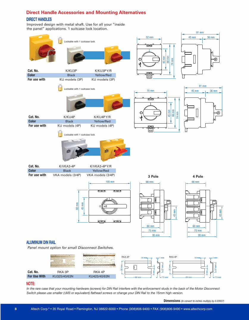
Cat. No. K/KU3P K/KU3P Y/RColor Black Yellow/RedFor use with KU models (3P) KU models (3P)
ALUMINUM DIN RAIL
Cat. No. RKA 3P RKA 4PFor Use With KU325/40/63N KU425/40/63N 84 mm
35 m
m
35 m
m
1 mm14 mm 14 mm
4 m
m
4 m
m
27 m
m
66 mm 7.5 mm
1 mm
27 m
m
7.5 mm
RKA 4PRKA 3P
NOTE:In the rare case that your mounting hardware (screws) for DIN Rail interfere with the enforcement studs in the back of the Motor DisconnectSwitch please use smaller (≤M3 or equivalent) flathead screws or change your DIN Rail to the 15mm high version.
Panel mount option for small Disconnect Switches.
74 m
m
45 m
m
66 m
m
45 mm 36 mm
81 mm
70 mm
95 mm
73 mm
60 mm
43 m
m
66 mm105 mm
0
1
82 m
m
45 m
m
95 mm
73 mm
60 mm
43 m
m
66 mm
Direct Handle Accessories and Mounting Alternatives
Cat. No. K/KU4P K/KU4P Y/RColor Black Yellow/RedFor use with KU models (4P) KU models (4P)
Cat. No. K/VKA3-4P K/VKA3-4P Y/RColor Black Yellow/RedFor use with VKA models (3/4P) VKA models (3/4P)
DIRECT HANDLESImproved design with metal shaft. Use for all your “insidethe panel” applications. 1 suitcase lock location.
Dimensions (to convert to inches multiply by 0.03937)
3 Pole 4 Pole
Lockable with 1 suitcase lock.
Lockable with 1 suitcase lock.
Lockable with 1 suitcase lock.
DrillTemplate &Instructions
Included
1/4” Padlocks1/4” Padlocks1/4” Padlocks
Lockable with up to 3 padlocks.
PANEL
discard
Altech Corp.® • 35 Royal Road • Flemington, NJ 08822-6000 • Phone (908)806-9400 • FAX (908)806-9490 • www.altechcorp.com 9
Shown with switch and display plate.(sold separately)
E185115
72 mm 38 mm Ø79 mm
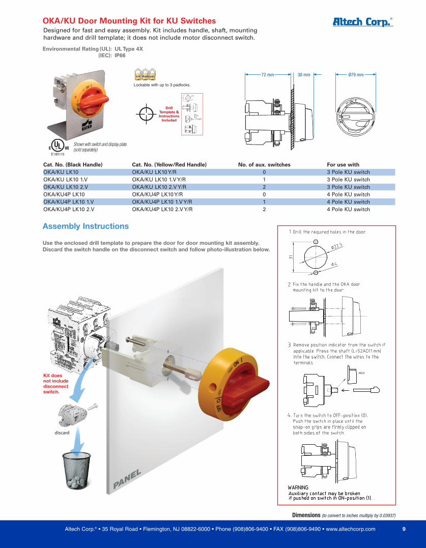
OKA/KU Door Mounting Kit for KU Switches
Environmental Rating (UL): UL Type 4X(IEC): IP66
Cat. No. (Black Handle) Cat. No. (Yellow/Red Handle) No. of aux. switches For use with OKA/KU LK10 OKA/KU LK10 Y/R 0 3 Pole KU switchOKA/KU LK10 1.V OKA/KU LK10 1.V Y/R 1 3 Pole KU switchOKA/KU LK10 2.V OKA/KU LK10 2.V Y/R 2 3 Pole KU switchOKA/KU4P LK10 OKA/KU4P LK10 Y/R 0 4 Pole KU switchOKA/KU4P LK10 1.V OKA/KU4P LK10 1.V Y/R 1 4 Pole KU switchOKA/KU4P LK10 2.V OKA/KU4P LK10 2.V Y/R 2 4 Pole KU switch
Designed for fast and easy assembly. Kit includes handle, shaft, mountinghardware and drill template; it does not include motor disconnect switch.
Dimensions (to convert to inches multiply by 0.03937)
Assembly Instructions
Use the enclosed drill template to prepare the door for door mounting kit assembly.Discard the switch handle on the disconnect switch and follow photo-illustration below.
Kit doesnot includedisconnectswitch.
DrillTemplate &Instructions
Included
1/4” Padlocks1/4” Padlocks1/4” Padlocks
Lockable with up to 3 padlocks.
Shown with switch and display plate.(sold separately)
72 mm 32 mm 70 mm
62 mm
66 m
m
62 m
m
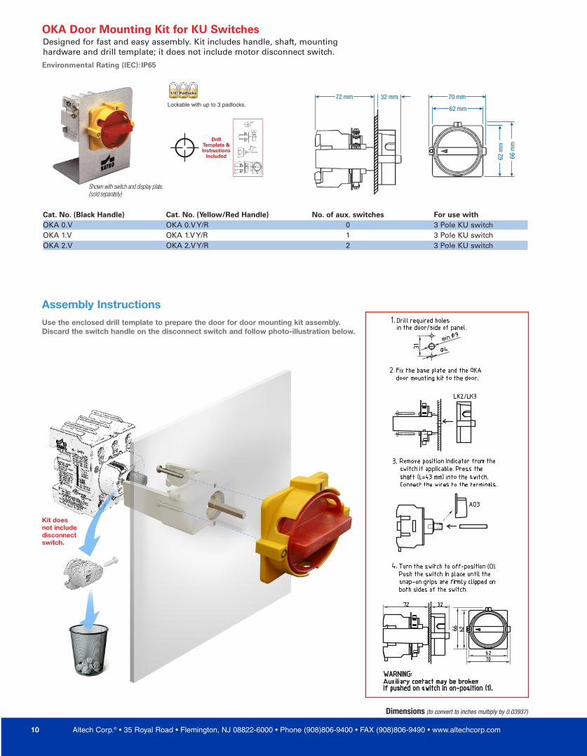
OKA Door Mounting Kit for KU Switches
Environmental Rating (IEC): IP65
Cat. No. (Black Handle) Cat. No. (Yellow/Red Handle) No. of aux. switches For use with OKA 0.V OKA 0.V Y/R 0 3 Pole KU switchOKA 1.V OKA 1.V Y/R 1 3 Pole KU switchOKA 2.V OKA 2.V Y/R 2 3 Pole KU switch
Dimensions (to convert to inches multiply by 0.03937)
Assembly InstructionsUse the enclosed drill template to prepare the door for door mounting kit assembly.Discard the switch handle on the disconnect switch and follow photo-illustration below.
Altech Corp.® • 35 Royal Road • Flemington, NJ 08822-6000 • Phone (908)806-9400 • FAX (908)806-9490 • www.altechcorp.com10
Kit doesnot includedisconnectswitch.
Designed for fast and easy assembly. Kit includes handle, shaft, mountinghardware and drill template; it does not include motor disconnect switch.

DrillTemplate &Instructions
Included
1/4” Padlocks1/4” Padlocks1/4” Padlocks
Lockable with up to 3 padlocks.
PANEL
Shown with switch.(sold separately)
E185115
OFF
ON
63mm
78.7
mm
82m
m
87mm 41mm
OKA/VKA Door Mounting Kit for VKA Switches
Environmental Rating (UL): UL Type 4X(IEC): IP66
Cat. No. (Black Handle) Cat. No. (Yellow/Red Handle) No. of aux. switches For use with OKA/VKA 0.V OKA/VKA 0.V Y/R 0 3 Pole VKA switchOKA/VKA 1.V OKA/VKA 1.V Y/R 1 3 Pole VKA switchOKA/VKA 2.V OKA/VKA 2.V Y/R 2 3 Pole VKA switchOKA/VKA4P 0.V OKA/VKA4P 0.V Y/R 0 4 Pole VKA switchOKA/VKA4P 1.V OKA/VKA4P 1.V Y/R 1 4 Pole VKA switchOKA/VKA4P 2.V OKA/VKA4P 2.V Y/R 2 4 Pole VKA switch
Dimensions (to convert to inches multiply by 0.03937)
Assembly InstructionsUse the enclosed drill template to prepare the door for door mounting kit assembly.Discard the switch handle on the disconnect switch and follow illustration below.
Altech Corp.® • 35 Royal Road • Flemington, NJ 08822-6000 • Phone (908)806-9400 • FAX (908)806-9490 • www.altechcorp.com 11
Kit doesnot includedisconnectswitch.
Designed for fast and easy assembly. Kit includes handle, shaft, mountinghardware and drill template; it does not include motor disconnect switch.