Embed Size (px)
Citation preview
© 2010, 2013 Cisco and/or its affiliates. All rights reserved. This document is Cisco Public. Page 1 of 12
Data Sheet
Extended Performance 10-Gbps Full-Band Tunable Multirate Transponder Card for the Cisco ONS 15454 Multiservice Transport Platform
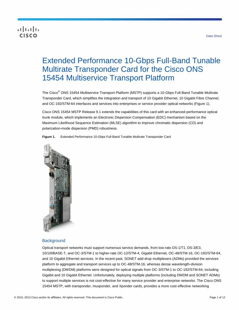
The Cisco® ONS 15454 Multiservice Transport Platform (MSTP) supports a 10-Gbps Full-Band Tunable Multirate
Transponder Card, which simplifies the integration and transport of 10 Gigabit Ethernet, 10 Gigabit Fibre Channel,
and OC-192/STM-64 interfaces and services into enterprises or service provider optical networks (Figure 1).
Cisco ONS 15454 MSTP Release 9.1 extends the capabilities of this card with an enhanced-performance optical
trunk module, which implements an Electronic Dispersion Compensation (EDC) mechanism based on the
Maximum Likelihood Sequence Estimation (MLSE) algorithm to improve chromatic dispersion (CD) and
polarization-mode dispersion (PMD) robustness.
Figure 1. Extended Performance 10-Gbps Full-Band Tunable Multirate Transponder Card
Background
Optical transport networks must support numerous service demands, from low-rate DS-1/T1, DS-3/E3,
10/100BASE-T, and OC-3/STM-1 to higher-rate OC-12/STM-4, Gigabit Ethernet, OC-48/STM-16, OC-192/STM-64,
and 10 Gigabit Ethernet services. In the recent past, SONET add-drop multiplexers (ADMs) provided the services
platform to aggregate and transport services up to OC-48/STM-16, whereas dense wavelength-division
multiplexing (DWDM) platforms were designed for optical signals from OC-3/STM-1 to OC-192/STM-64, including
Gigabit and 10 Gigabit Ethernet. Unfortunately, deploying multiple platforms (including DWDM and SONET ADMs)
to support multiple services is not cost-effective for many service provider and enterprise networks. The Cisco ONS
15454 MSTP, with transponder, muxponder, and Xponder cards, provides a more cost-effective networking

© 2010, 2013 Cisco and/or its affiliates. All rights reserved. This document is Cisco Public. Page 2 of 12
solution to enable the delivery of all services, from lower-speed DS-1/E1 to high-density 2.5 Gbps and high-
bandwidth OC-192/STM-64.
Product Overview
The 10-Gbps Full-Band Tunable Multirate Transponder Card can transport 10 Gigabit Ethernet WAN physical layer
(PHY) and LAN PHY, 10-Gbps Fibre Channel (10G FICON), SONET OC-192, and SDH STM-64 services over a
50-GHz spaced, 50-GHz stabilized, ITU-compliant wavelength. The transponder card is a plug-in module to the
Cisco ONS 15454 MSTP, enabling a cost-effective architecture for delivering high-rate 10-Gbps services as well as
low-rate services down to 1.5 Mbps. The transponder card architecture contains a single client interface that is
mapped to a single line interface, without accessing the Cisco ONS 15454 shelf cross-connect fabric.
The client interface supports 10 Gigabit Ethernet LAN PHY, 10 Gigabit Ethernet WAN PHY, 10 Gigabit Fibre
Channel, SONET OC-192, and SDH STM-64 signals. The interface is based on 10 Gigabit Small Form-Factor
Pluggable (XFP) Multisource Agreement (MSA). Different XFP interfaces are available:
● A 10GE BASE-short-wave/short-reach, 850-nanometer (nm), multimode (MM) optical interface using LC
connectors supporting fiber distance of up to 300 meters (m) (with or without the Y-protection option)
● A short-reach/intra-office, 1310-nm, single-mode (SM) optical interface using LC connectors supporting fiber
distances of up to 2 kilometers (km) (with or without the Y-protection option)
● An intermediate-reach/short-haul, 1550-nm, SM optical interface using LC connectors supporting fiber
distances of up to 20 km (with or without the Y-protection option)
● A long-reach/long-haul, 1550-nm, SM optical interface using LC connectors supporting fiber distances of up
to 80 km (with or without the Y-protection option)
The line interface provides one 10-Gbps, long-reach, ITU-compliant, 50-GHz-spaced optical interface using LC
connectors supporting OTU-2 G.709 digital wrapper, OC-192, STM-64, 10 Gigabit Fibre Channel, 10 Gigabit
Ethernet LAN PHY, or 10 Gigabit Ethernet WAN PHY interfaces.
The DWDM trunk interface is fully tunable across 82 adjacent 50-GHz wavelengths, enabling support for C-Band
DWDM networks via a single card type. The MLSE-based Electronic Dispersion Compensation extends DWDM
network performances, providing support to the following applications:
● High PMD fiber applications: MLSE technology can monitor and correct errors due to time variant effects
● Low-latency data center applications: SAN protocols, such as Server Time Protocol (STP), are extremely
sensitive to additional latency introduced by CD optical fiber.
● Enterprise point-to-point applications: Installation costs for the dispersion compensation unit (DCU) and
fiber can be avoided. This is particularly important in low-end markets, where DCU can comprise up to 10
percent of simple point-to-point systems cost.
● Ultra-long-haul (ULH) applications: Improvement in CD and PMD performance can be translated into
better ULH performance. Additional OSNR margin can be allocated to compensate for non-linear effects
(NLE) impairment, allowing for better system performance.
The 10-Gbps Full-Band Tunable Multirate Transponder Card incorporates both a client and DWDM line interface
on the same card. The 10-Gbps full-band tunable transponder cards are deployable in the 12 multiservice interface
card slots of the Cisco ONS 15454 platform, in systems with or without cross-connect cards. The addition of a
cross-connect card enables the platform to support hybrid applications, containing transparent 10-Gbps services as
© 2010, 2013 Cisco and/or its affiliates. All rights reserved. This document is Cisco Public. Page 3 of 12
well as aggregation of other services supported by the Cisco ONS 15454 platform. The only required common card
is the appropriate timing, communications, and control card (TCC).
The 10-Gbps Full-Band Tunable Multirate Transponder Card provides many carrier-class features and advanced
capabilities necessary to deliver 10-Gbps services, including the protocol transparency, wavelength tunability,
flexible protection mechanisms, flow-through timing, management, and performance monitoring capabilities
outlined below.
Enhanced FEC Capability
An important feature of the transponder card is the availability to configure the Forward Error Correction (FEC) in
two modes: FEC and Enhanced FEC (E-FEC). The output bit rate will depend on the bit rate of the incoming signal
but the digital wrapper will be always as defined in G.709.
● 10.70923 Gbps in case of OC-192/STM-64/10 Gigabit Ethernet WAN
● 11.095 Gbps in case of 10 Gigabit Ethernet LAN PHY (over-clocking mode)
● 11.3168 Gbps in case of 10 Gigabit Fibre Channel (over-clocking mode)
Error coding performance can be provisioned:
● FEC: standard G.975 Reed-Salomon algorithm
● E-FEC: standard G.975.1 two orthogonally concatenated BCH super FEC codes. This FEC scheme
contains three parameterizations of the same scheme of two orthogonally interleaved block codes (BCH).
The constructed code is decoded iteratively, to achieve the expected performance.
Protocol Transparency
The transponder card provides transparent wavelength services on the Cisco ONS 15454 platform. For SONET-
or SDH-based client payloads, when provisioned in transparent operating mode, the card will pass all of the
SONET/SDH overhead bytes transparently. The card monitors important SONET/SDH overhead bytes, such as B1
(section BIP-8) and J0 (section trace), to allow fault isolation and performance monitoring capabilities. Termination
of the line data communications channel (LDCC) is user-provisionable, to enable the platform processor to route
the DCC information for intra-carrier networking or to allow the DCC information to be transported untouched, via
the digital wrapper’s general communications channel (GCC), for inter-carrier networking. For 10 Gigabit Ethernet
and OC-192/STM-64 payloads, digital wrapper technology (G.709) is used to add a management wrapper to the
service, allowing the transponder card to transparently forward the payload while enabling performance metrics to
be derived to ensure circuit service quality.
The transponder card is transparent to the embedded payload and does not access the Cisco ONS 15454
platform’s cross-connect. It can carry any type of concatenated SONET/SDH payloads (STS-Nc or VC-4-Mc); non-
concatenated payloads on an STS-1, VC-4, VC-3, VC-12, or VT1.5 basis; and 10 Gigabit Ethernet LAN or WAN
PHY payloads.
Wavelength Tunability
The transponder card operates on the 50-GHz ITU grid and it is tunable across the full C-band, on 50-GHz
channels. Tunability reduces the amount of inventory and spares required to cover all of the wavelengths.
Tunability is software-provisionable.
© 2010, 2013 Cisco and/or its affiliates. All rights reserved. This document is Cisco Public. Page 4 of 12
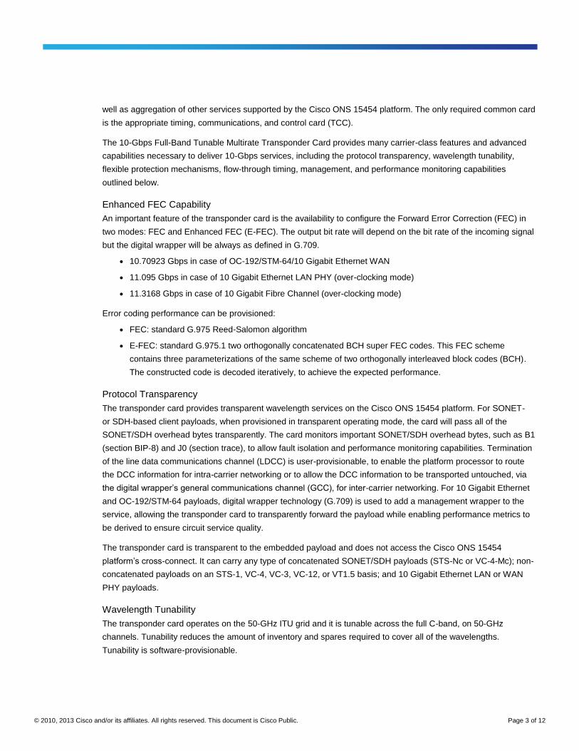
Flexible Protection Mechanisms
The 10-Gbps Full-Band Tunable Multirate Transponder Card provides flexible protection capabilities for both client
and DWDM line interfaces, enabling support for numerous network configurations required to deliver the various
service-level agreements (SLAs) for customer applications (Table 1).
Table 1. Protection Formats
Protection Type Capabilities Figure
Unprotected client and line
No client terminal interface, transponder card, or DWDM line protection. The client signal is transported over a single unprotected transponder card. This configuration is suitable for transporting client payloads over a DWDM network that is being protected via unidirectional path switched ring/subnetwork connection protection (UPSR/SNCP) or bidirectional line switched ring/multiplex section shared protection ring (BLSR/MS-SPR) protocols.
2
1+1 protected client Enables protection for both the client terminal interfaces and the transponder cards. Two client terminal interfaces operating 1+1 automatic protection switching/multiplex section protection (APS/MSP) switching are passed through 2 transponder cards, with switching managed between client terminal equipment interfaces.
3
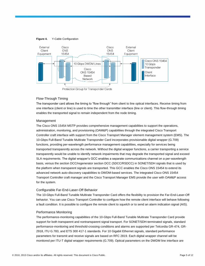
Y-cable client interface Provides transponder equipment protection without client terminal equipment interface protection. A single client interface is split to 2 transponder cards using a Y-protection device.
4
Figure 2. Unprotected Configuration
Figure 3. 1+1 Configurations
© 2010, 2013 Cisco and/or its affiliates. All rights reserved. This document is Cisco Public. Page 5 of 12
Figure 4. Y-Cable Configuration
Flow-Through Timing
The transponder card allows the timing to “flow through” from client to line optical interfaces. Receive timing from
one interface (client or line) is used to time the other transmitter interface (line or client). This flow-through timing
enables the transported signal to remain independent from the node timing.
Management
The Cisco ONS 15454 MSTP provides comprehensive management capabilities to support the operations,
administration, monitoring, and provisioning (OAM&P) capabilities through the integrated Cisco Transport
Controller craft interface with support from the Cisco Transport Manager element management system (EMS). The
10-Gbps Full-Band Tunable Multirate Transponder Card incorporates provisionable digital wrapper (G.709)
functions, providing per-wavelength performance management capabilities, especially for services being
transported transparently across the network. Without the digital wrapper functions, a carrier transporting a service
transparently would be unable to identify network impairments that may degrade the transported signal and exceed
SLA requirements. The digital wrapper’s GCC enables a separate communications channel on a per-wavelength
basis, versus the section DCC/regenerator section DCC (SDCC/RSDCC) in SONET/SDH signals that is used by
the platform when transparent signals are transported. This GCC enables the Cisco ONS 15454 to extend its
advanced network auto-discovery capabilities to DWDM-based services. The integrated Cisco ONS 15454
Transport Controller craft manager and the Cisco Transport Manager EMS provide the user with OAM&P access
for the system.
Configurable Far-End-Laser-Off Behavior
The 10-Gbps Full-Band Tunable Multirate Transponder Card offers the flexibility to provision the Far-End-Laser-Off
behavior. You can use Cisco Transport Controller to configure how the remote client interface will behave following
a fault condition. It is possible to configure the remote client to squelch or to send an alarm indication signal (AIS).
Performance Monitoring
The performance-monitoring capabilities of the 10-Gbps Full-Band Tunable Multirate Transponder Card provide
support for both transparent and nontransparent signal transport. For SONET/SDH-terminated signals, standard
performance-monitoring and threshold-crossing conditions and alarms are supported per Telcordia GR-474, GR-
2918, ITU G.783, and ETS 300 417-1 standards. For 10 Gigabit Ethernet signals, standard performance
parameters for transmit and receive signals are based on RFC 2819. Each digital wrapper channel will be
monitored per ITU-T digital wrapper requirements (G.709). Optical parameters on the DWDM line interface are
© 2010, 2013 Cisco and/or its affiliates. All rights reserved. This document is Cisco Public. Page 6 of 12
supported, including laser bias, transmit optical power, and receiver optical power. Calculation and accumulation of
the performance monitoring data will be in 15-minute and 24-hour intervals.
The transponder card incorporates faceplate-mounted LEDs to provide a quick visual check of the operational
status of the card. An orange circle is printed on the faceplate, indicating the shelf slots the card can be installed.
Application Description
The 10-Gbps Full-Band Tunable Multirate Transponder Card adds several new applications to an already flexible
Cisco ONS 15454 platform. These include metro 10 Gigabit Ethernet connectivity, STM-64 transport for cable-
landing service extension, and OC-192/STM-64 transport for carrier services.
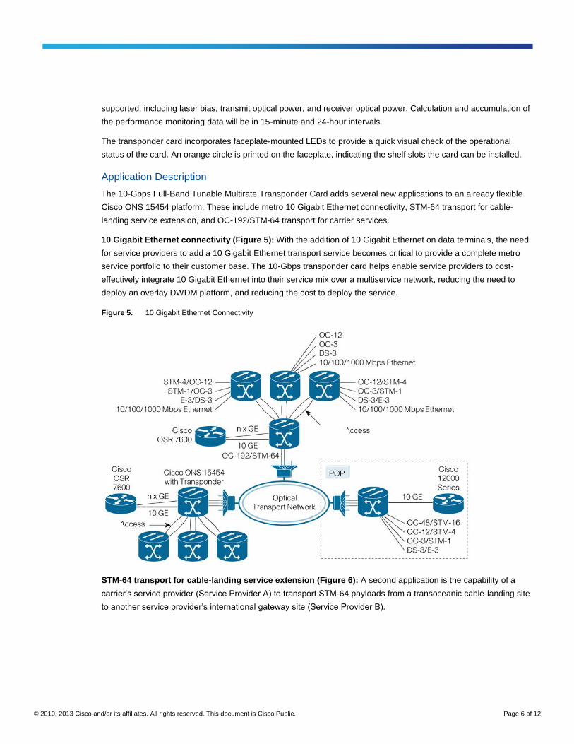
10 Gigabit Ethernet connectivity (Figure 5): With the addition of 10 Gigabit Ethernet on data terminals, the need
for service providers to add a 10 Gigabit Ethernet transport service becomes critical to provide a complete metro
service portfolio to their customer base. The 10-Gbps transponder card helps enable service providers to cost-
effectively integrate 10 Gigabit Ethernet into their service mix over a multiservice network, reducing the need to
deploy an overlay DWDM platform, and reducing the cost to deploy the service.
Figure 5. 10 Gigabit Ethernet Connectivity
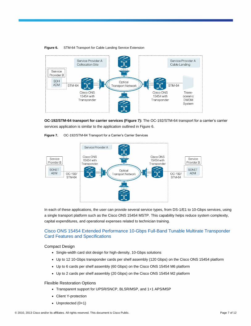
STM-64 transport for cable-landing service extension (Figure 6): A second application is the capability of a
carrier’s service provider (Service Provider A) to transport STM-64 payloads from a transoceanic cable-landing site
to another service provider’s international gateway site (Service Provider B).
© 2010, 2013 Cisco and/or its affiliates. All rights reserved. This document is Cisco Public. Page 7 of 12
Figure 6. STM-64 Transport for Cable Landing Service Extension
OC-192/STM-64 transport for carrier services (Figure 7): The OC-192/STM-64 transport for a carrier’s carrier
services application is similar to the application outlined in Figure 6.
Figure 7. OC-192/STM-64 Transport for a Carrier’s Carrier Services
In each of these applications, the user can provide several service types, from DS-1/E1 to 10-Gbps services, using
a single transport platform such as the Cisco ONS 15454 MSTP. This capability helps reduce system complexity,
capital expenditures, and operational expenses related to technician training.
Cisco ONS 15454 Extended Performance 10-Gbps Full-Band Tunable Multirate Transponder
Card Features and Specifications
Compact Design
● Single-width card slot design for high-density, 10-Gbps solutions
● Up to 12 10-Gbps transponder cards per shelf assembly (120 Gbps) on the Cisco ONS 15454 platform
● Up to 6 cards per shelf assembly (60 Gbps) on the Cisco ONS 15454 M6 platform
● Up to 2 cards per shelf assembly (20 Gbps) on the Cisco ONS 15454 M2 platform
Flexible Restoration Options
● Transparent support for UPSR/SNCP, BLSR/MSP, and 1+1 APS/MSP
● Client Y-protection
● Unprotected (0+1)
© 2010, 2013 Cisco and/or its affiliates. All rights reserved. This document is Cisco Public. Page 8 of 12
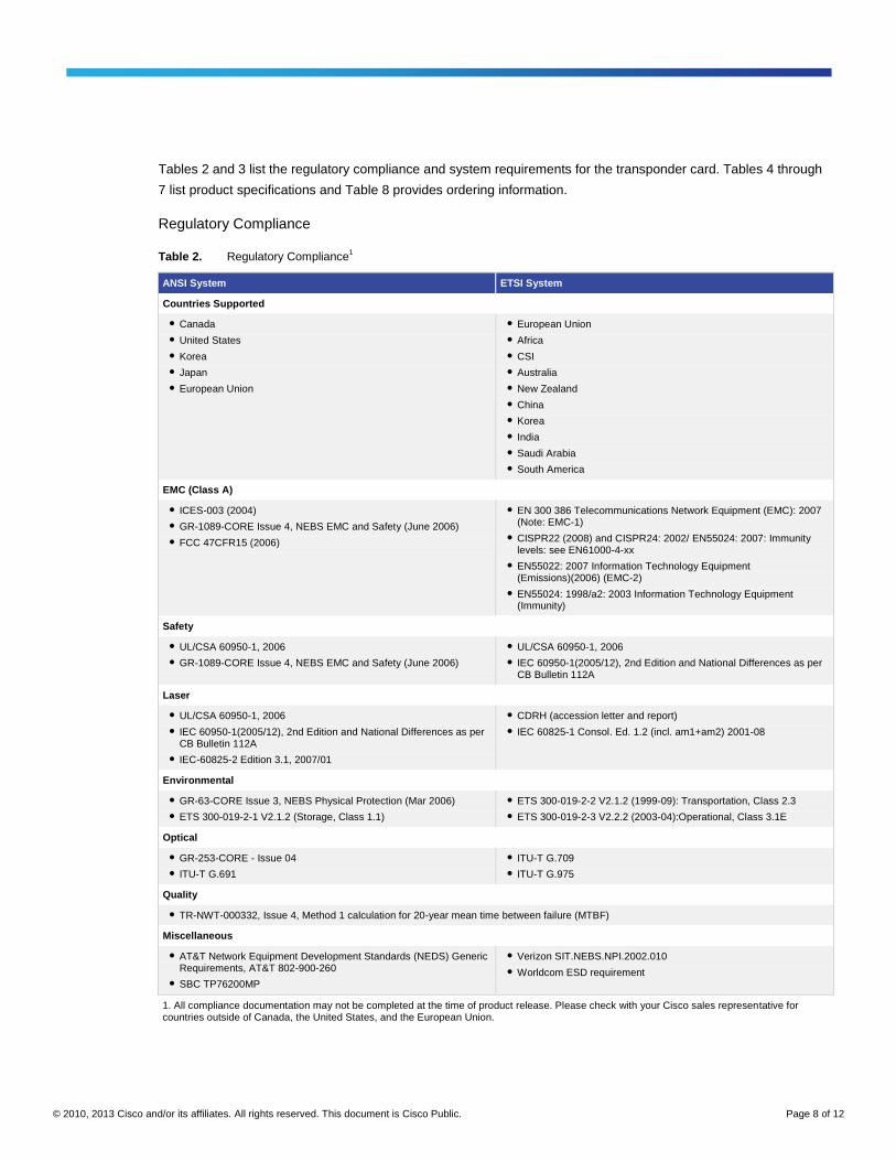
Tables 2 and 3 list the regulatory compliance and system requirements for the transponder card. Tables 4 through
7 list product specifications and Table 8 provides ordering information.
Regulatory Compliance
Table 2. Regulatory Compliance1
ANSI System ETSI System
Countries Supported
● Canada
● United States
● Korea
● Japan
● European Union
● European Union
● Africa
● CSI
● Australia
● New Zealand
● China
● Korea
● India
● Saudi Arabia
● South America
EMC (Class A)
● ICES-003 (2004)
● GR-1089-CORE Issue 4, NEBS EMC and Safety (June 2006)
● FCC 47CFR15 (2006)
● EN 300 386 Telecommunications Network Equipment (EMC): 2007 (Note: EMC-1)
● CISPR22 (2008) and CISPR24: 2002/ EN55024: 2007: Immunity levels: see EN61000-4-xx
● EN55022: 2007 Information Technology Equipment (Emissions)(2006) (EMC-2)
● EN55024: 1998/a2: 2003 Information Technology Equipment (Immunity)
Safety
● UL/CSA 60950-1, 2006
● GR-1089-CORE Issue 4, NEBS EMC and Safety (June 2006)
● UL/CSA 60950-1, 2006
● IEC 60950-1(2005/12), 2nd Edition and National Differences as per CB Bulletin 112A
Laser
● UL/CSA 60950-1, 2006
● IEC 60950-1(2005/12), 2nd Edition and National Differences as per CB Bulletin 112A
● IEC-60825-2 Edition 3.1, 2007/01
● CDRH (accession letter and report)
● IEC 60825-1 Consol. Ed. 1.2 (incl. am1+am2) 2001-08
Environmental
● GR-63-CORE Issue 3, NEBS Physical Protection (Mar 2006)
● ETS 300-019-2-1 V2.1.2 (Storage, Class 1.1)
● ETS 300-019-2-2 V2.1.2 (1999-09): Transportation, Class 2.3
● ETS 300-019-2-3 V2.2.2 (2003-04):Operational, Class 3.1E
Optical
● GR-253-CORE - Issue 04
● ITU-T G.691
● ITU-T G.709
● ITU-T G.975
Quality
● TR-NWT-000332, Issue 4, Method 1 calculation for 20-year mean time between failure (MTBF)
Miscellaneous
● AT&T Network Equipment Development Standards (NEDS) Generic Requirements, AT&T 802-900-260
● SBC TP76200MP
● Verizon SIT.NEBS.NPI.2002.010
● Worldcom ESD requirement
1. All compliance documentation may not be completed at the time of product release. Please check with your Cisco sales representative for countries outside of Canada, the United States, and the European Union.
© 2010, 2013 Cisco and/or its affiliates. All rights reserved. This document is Cisco Public. Page 9 of 12
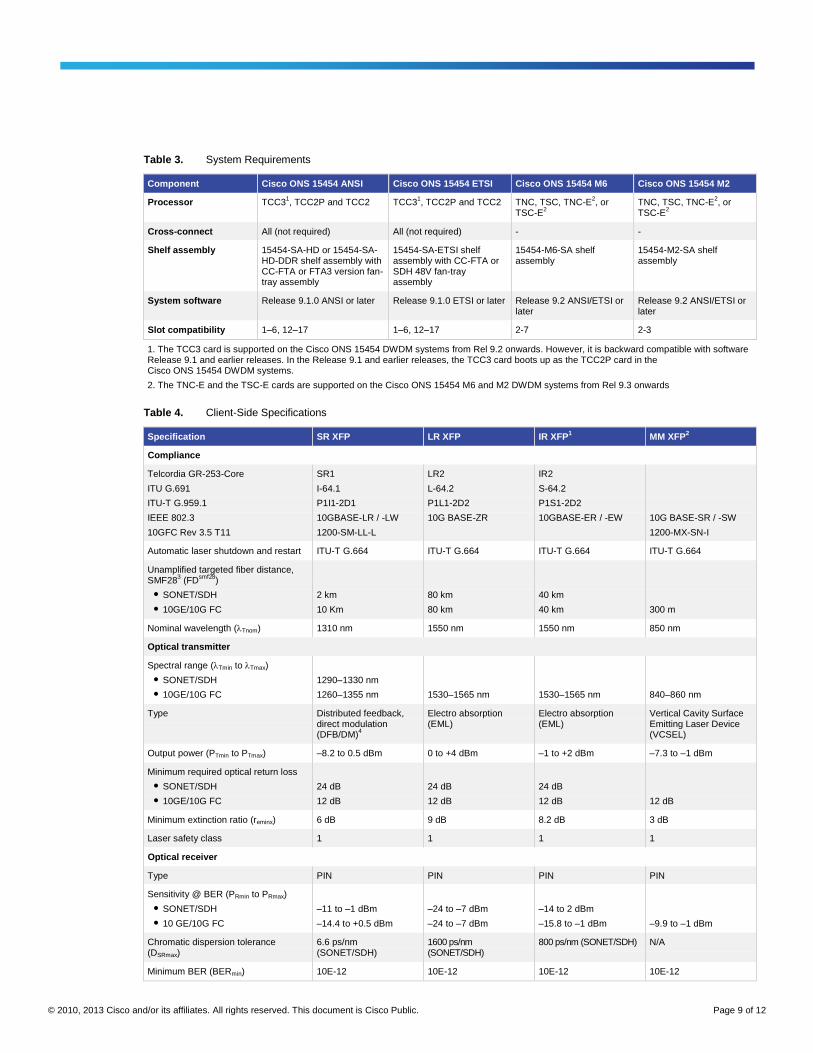
Table 3. System Requirements
Component Cisco ONS 15454 ANSI Cisco ONS 15454 ETSI Cisco ONS 15454 M6 Cisco ONS 15454 M2
Processor TCC31, TCC2P and TCC2 TCC3
1, TCC2P and TCC2 TNC, TSC, TNC-E
2, or
TSC-E2
TNC, TSC, TNC-E2, or
TSC-E2
Cross-connect All (not required) All (not required) - -
Shelf assembly 15454-SA-HD or 15454-SA-HD-DDR shelf assembly with CC-FTA or FTA3 version fan-tray assembly
15454-SA-ETSI shelf assembly with CC-FTA or SDH 48V fan-tray assembly
15454-M6-SA shelf assembly
15454-M2-SA shelf assembly
System software Release 9.1.0 ANSI or later Release 9.1.0 ETSI or later Release 9.2 ANSI/ETSI or later
Release 9.2 ANSI/ETSI or later
Slot compatibility 1–6, 12–17 1–6, 12–17 2-7 2-3
1. The TCC3 card is supported on the Cisco ONS 15454 DWDM systems from Rel 9.2 onwards. However, it is backward compatible with software Release 9.1 and earlier releases. In the Release 9.1 and earlier releases, the TCC3 card boots up as the TCC2P card in the Cisco ONS 15454 DWDM systems.
2. The TNC-E and the TSC-E cards are supported on the Cisco ONS 15454 M6 and M2 DWDM systems from Rel 9.3 onwards
Table 4. Client-Side Specifications
Specification SR XFP LR XFP IR XFP1 MM XFP
2
Compliance
Telcordia GR-253-Core
ITU G.691
ITU-T G.959.1
IEEE 802.3
10GFC Rev 3.5 T11
SR1
I-64.1
P1I1-2D1
10GBASE-LR / -LW
1200-SM-LL-L
LR2
L-64.2
P1L1-2D2
10G BASE-ZR
IR2
S-64.2
P1S1-2D2
10GBASE-ER / -EW
10G BASE-SR / -SW
1200-MX-SN-I
Automatic laser shutdown and restart ITU-T G.664 ITU-T G.664 ITU-T G.664 ITU-T G.664
Unamplified targeted fiber distance, SMF28
3 (FD
smf28)
● SONET/SDH
● 10GE/10G FC
2 km
10 Km
80 km
80 km
40 km
40 km
300 m
Nominal wavelength (Tnom) 1310 nm 1550 nm 1550 nm 850 nm
Optical transmitter
Spectral range (Tmin to Tmax)
● SONET/SDH
● 10GE/10G FC
1290–1330 nm
1260–1355 nm
1530–1565 nm
1530–1565 nm
840–860 nm
Type Distributed feedback, direct modulation (DFB/DM)
4
Electro absorption (EML)
Electro absorption (EML)
Vertical Cavity Surface Emitting Laser Device (VCSEL)
Output power (PTmin to PTmax) –8.2 to 0.5 dBm 0 to +4 dBm –1 to +2 dBm –7.3 to –1 dBm
Minimum required optical return loss
● SONET/SDH
● 10GE/10G FC
24 dB
12 dB
24 dB
12 dB
24 dB
12 dB
12 dB
Minimum extinction ratio (reminx) 6 dB 9 dB 8.2 dB 3 dB
Laser safety class 1 1 1 1
Optical receiver
Type PIN PIN PIN PIN
Sensitivity @ BER (PRmin to PRmax)
● SONET/SDH
● 10 GE/10G FC
–11 to –1 dBm
–14.4 to +0.5 dBm
–24 to –7 dBm
–24 to –7 dBm
–14 to 2 dBm
–15.8 to –1 dBm
–9.9 to –1 dBm
Chromatic dispersion tolerance (DSRmax)
6.6 ps/nm (SONET/SDH)
1600 ps/nm (SONET/SDH)
800 ps/nm (SONET/SDH) N/A
Minimum BER (BERmin) 10E-12 10E-12 10E-12 10E-12
© 2010, 2013 Cisco and/or its affiliates. All rights reserved. This document is Cisco Public. Page 10 of 12
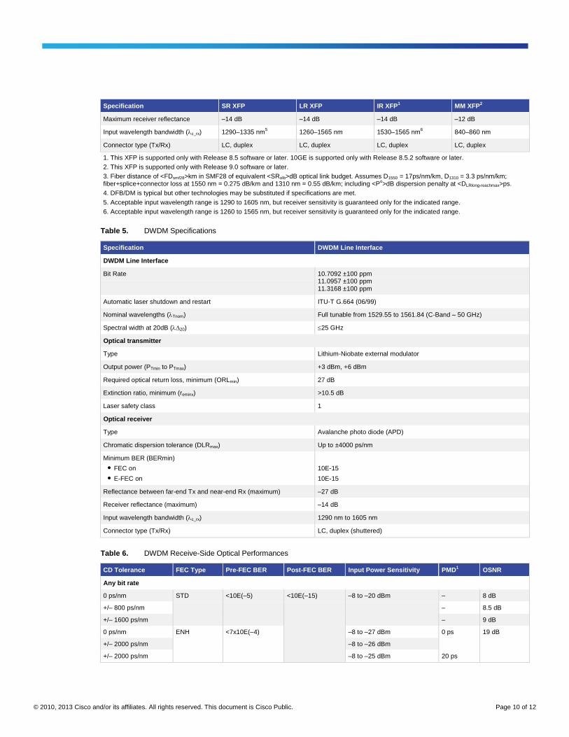
Specification SR XFP LR XFP IR XFP1 MM XFP
2
Maximum receiver reflectance –14 dB –14 dB –14 dB –12 dB
Input wavelength bandwidth (c_rx) 1290–1335 nm5 1260–1565 nm 1530–1565 nm
6 840–860 nm
Connector type (Tx/Rx) LC, duplex LC, duplex LC, duplex LC, duplex
1. This XFP is supported only with Release 8.5 software or later. 10GE is supported only with Release 8.5.2 software or later.
2. This XFP is supported only with Release 9.0 software or later.
3. Fiber distance of <FDsmf28>km in SMF28 of equivalent <SRolb>dB optical link budget. Assumes D1550 = 17ps/nm/km, D1310 = 3.3 ps/nm/km; fiber+splice+connector loss at 1550 nm = 0.275 dB/km and 1310 nm = 0.55 dB/km; including <P
o>dB dispersion penalty at <DLRlong-reachmax>ps.
4. DFB/DM is typical but other technologies may be substituted if specifications are met.
5. Acceptable input wavelength range is 1290 to 1605 nm, but receiver sensitivity is guaranteed only for the indicated range.
6. Acceptable input wavelength range is 1260 to 1565 nm, but receiver sensitivity is guaranteed only for the indicated range.
Table 5. DWDM Specifications
Specification DWDM Line Interface
DWDM Line Interface
Bit Rate 10.7092 ±100 ppm 11.0957 ±100 ppm 11.3168 ±100 ppm
Automatic laser shutdown and restart ITU-T G.664 (06/99)
Nominal wavelengths (Tnom) Full tunable from 1529.55 to 1561.84 (C-Band – 50 GHz)
Spectral width at 20dB (20) 25 GHz
Optical transmitter
Type Lithium-Niobate external modulator
Output power (PTmin to PTmax) +3 dBm, +6 dBm
Required optical return loss, minimum (ORLmin) 27 dB
Extinction ratio, minimum (reminx) >10.5 dB
Laser safety class 1
Optical receiver
Type Avalanche photo diode (APD)
Chromatic dispersion tolerance (DLRmax) Up to ±4000 ps/nm
Minimum BER (BERmin)
● FEC on
● E-FEC on
10E-15
10E-15
Reflectance between far-end Tx and near-end Rx (maximum) –27 dB
Receiver reflectance (maximum) –14 dB
Input wavelength bandwidth (c_rx) 1290 nm to 1605 nm
Connector type (Tx/Rx) LC, duplex (shuttered)
Table 6. DWDM Receive-Side Optical Performances
CD Tolerance FEC Type Pre-FEC BER Post-FEC BER Input Power Sensitivity PMD1 OSNR
Any bit rate
0 ps/nm STD <10E(–5) <10E(–15) –8 to –20 dBm – 8 dB
+/– 800 ps/nm – 8.5 dB
+/– 1600 ps/nm – 9 dB
0 ps/nm ENH <7x10E(–4) –8 to –27 dBm 0 ps 19 dB
+/– 2000 ps/nm –8 to –26 dBm
+/– 2000 ps/nm –8 to –25 dBm 20 ps
© 2010, 2013 Cisco and/or its affiliates. All rights reserved. This document is Cisco Public. Page 11 of 12
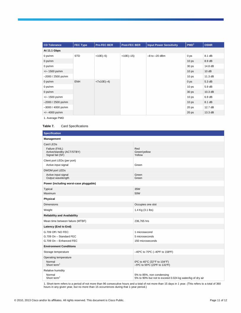
CD Tolerance FEC Type Pre-FEC BER Post-FEC BER Input Power Sensitivity PMD1 OSNR
At 11.1 Gbps
0 ps/nm STD <10E(–5) <10E(–15) –8 to –20 dBm 0 ps 8.1 dB
0 ps/nm 10 ps 8.9 dB
0 ps/nm 30 ps 14.8 dB
+/– 1500 ps/nm 10 ps 10 dB
–2000 / 2500 ps/nm 10 ps 11.3 dB
0 ps/nm ENH <7x10E(–4) 0 ps 5.3 dB
0 ps/nm 10 ps 5.9 dB
0 ps/nm 30 ps 10.3 dB
+/– 1500 ps/nm 10 ps 6.9 dB
–2000 / 2500 ps/nm 10 ps 8.1 dB
–3000 / 4000 ps/nm 20 ps 12.7 dB
+/– 4000 ps/nm 20 ps 13.3 dB
1. Average PMD
Table 7. Card Specifications
Specification
Management
Card LEDs
Failure (FAIL) Active/standby (ACT/STBY) Signal fail (SF)
Red Green/yellow Yellow
Client port LEDs (per port)
Active input signal
Green
DWDM port LEDs
Active input signal Output wavelength
Green Green
Power (including worst-case pluggable)
Typical
Maximum
35W
50W
Physical
Dimensions Occupies one slot
Weight 1.4 Kg (3.1 lbs)
Reliability and Availability
Mean time between failure (MTBF) 236,765 hrs
Latency (End to End)
G.709 Off / NO FEC:
G.709 On – Standard FEC
G.709 On – Enhanced FEC
1 microsecond
5 microseconds
150 microseconds
Environment Conditions
Storage temperature –40ºC to 70ºC (–40ºF to 158ºF)
Operating temperature
Normal Short term
1
0ºC to 40°C (32°F to 104°F) –5ºC to 55ºC (23ºF to 131ºF)
Relative humidity
Normal Short term
1
5% to 85%, non condensing 5% to 90% but not to exceed 0.024 kg water/kg of dry air
1. Short-term refers to a period of not more than 96 consecutive hours and a total of not more than 15 days in 1 year. (This refers to a total of 360 hours in any given year, but no more than 15 occurrences during that 1-year period.)
© 2010, 2013 Cisco and/or its affiliates. All rights reserved. This document is Cisco Public. Page 12 of 12
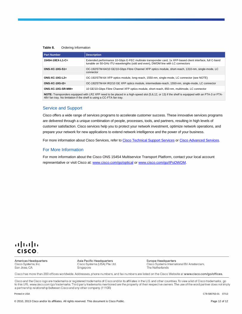
Table 8. Ordering Information
Part Number Description
15454-10EX-L1-C= Extended performance 10-Gbps E-FEC multirate transponder card, 1x XFP-based client interface, full C-band tunable on 50-GHz ITU wavelengths (odd and even), DWDM line with LC connectors
ONS-XC-10G-S1= OC-192/STM-64/10 GE/10-Gbps Fibre Channel XFP optics module, short-reach, 1310-nm, single-mode, LC connector
ONS-XC-10G-L2= OC-192/STM-64 XFP optics module, long-reach, 1550-nm, single-mode, LC connector (see NOTE)
ONS-XC-10G-I2= OC-192/STM-64 IR2/10 GE XFP optics module, intermediate-reach, 1550-nm, single-mode, LC connector
ONS-XC-10G-SR-MM= 10 GE/10-Gbps Fibre Channel XFP optics module, short-reach, 850-nm, multimode, LC connector
NOTE: Transponders equipped with LR2 XFP need to be placed in a high-speed slot (5,6,12, or 13) if the shelf is equipped with an FTA-3 or FTA-48V fan tray. No limitation if the shelf is using a CC-FTA fan tray.
Service and Support
Cisco offers a wide range of services programs to accelerate customer success. These innovative services programs
are delivered through a unique combination of people, processes, tools, and partners, resulting in high levels of
customer satisfaction. Cisco services help you to protect your network investment, optimize network operations, and
prepare your network for new applications to extend network intelligence and the power of your business.
For more information about Cisco Services, refer to Cisco Technical Support Services or Cisco Advanced Services.
For More Information
For more information about the Cisco ONS 15454 Multiservice Transport Platform, contact your local account
representative or visit Cisco at: Uwww.cisco.com/go/optical U or Uwww.cisco.com/go/IPoDWDMU.
Printed in USA C78-580763-01 07/13