Embed Size (px)
Citation preview
Installation manual
1
V1.3
· 09
.201
7 · S
ubje
ct to
mod
ificat
ion
EXT-T24-D201 LCD Temperature Controller
Installation
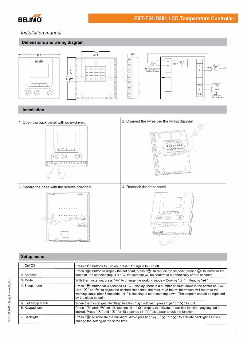
Dimensions and wiring diagram
24 VACL
N
R S
┴
Input
┴
~TR
M
V +
┴ ~
Modulating Control Cooling/ Heating
2-10 V
Input
Remote Sensor
1. Open the back panel with screwdriver. 2. Connect the wires per the wiring diagram.
3. Secure the base with the screws provided. 4. Reattach the front panel.
1. On/ Off
2. SetpointPress “ ” button to display the set point, press “ ” to reduce the setpoint, press “ ” to increase the setpoint, the setpoint step is 0.5°C, the setpoint will be confirmed automatically after 5 seconds.
3. Mode With thermostat on, press “ ” to change the working mode – Cooling “ ”, Heating “ ”.4. Sleep mode Press “ ” button for 3 seconds till “ ” display, there is a number of count down in the center of LCD.
Use “ ” or “ ” to adjust the desired sleep time: the max. = 48 hours; thermostat will return to the working status after 5 seconds, “ ” is flashing to start counting down. The setpoint should be replacedby the sleep setpoint.
When thermostat get into Sleep function, “ ” will flash, press “ ” or “ ” to quit. 5. Exit setup menu6. Keypad lock Press “ ” and “ ” for 10 seconds till to “ ” display to activate, under this function, any keypad is
locked. Press “ ” and “ ” for 10 seconds till “ ” disappear to quit the function.
Setup menu
Press “ ” buttons to turn on; press “ ” again to turn off.S
M
M
7. Backlight Press “ ” to activiate the backlight. Avoid pressing “ ”, “ ” or “ ” to activate backlight as it will change the setting at the same time.
S M
V1.
3 · 0
9.20
17 ·
Sub
ject
to m
odifi
catio
n
2
EXT-T24-D201 LCD Temperature Controller
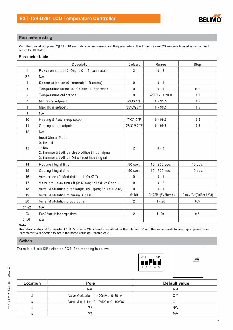
Parameter setting
Parameter table
With thermostat off, press “ ” for 10 seconds to enter menu to set the parameters. It will confirm itself 20 seconds later after setting and return to Off state.
M
r
D escrip tion D efau lt R ange S tep 1 P ower on s ta tus (0 : O ff; 1 : O n ; 2 : Last status) 2 0 - 2
2-3 N/A4 S ensor se lection (0 : In te rna l; 1 : R em ote ) 0 0 - 1 5 Tem pera tu re fo rm at (0 : C e ls ius; 1 : Fahrenheit) 0 0 - 1 0 .1 6 Tem pera tu re ca lib ra tion 0 -20 .0 - ﹢20.0 0 .1 7 M in im um se tpoin t 5℃/41℉ 0 - 99 .5 0 .5 8 M a xim um se tpo in t 35℃/96 ℉
℉
0 - 99 .5 0 .5 9 N/A
10 H eating & A u to s leep se tpo in t 7℃/45℉ 0 - 99 .5 0 .5 11 C oo ling sleep setpoin t 28℃ /82 ℉
℉
0 - 99 .5 0 .5 12 N/A
13
Inpu t S igna l M ode 0 : Inva lid 1 : N/A2 : the rm osta t w ill be s leep w ithou t inpu t s igna l 3 : the rm osta t w ill be O ff w ithou t inpu t s igna l
2 0 - 3
14 H eating integral tim e 90 sec. 10 - 300 sec. 10 sec. 15 C oo ling integral tim e 90 sec. 10 - 300 sec. 10 sec. 16 Valve m ode (0 : M odu la tion ; 1 : O n/O ff) 0 0 - 1 17 V a lve s tatus as tu rn o ff (0 : C lose; 1 :H o ld ; 2 : O pen ) 0 0 - 2 18 Valve M odu la tion d irec tion(0 :10V O pen; 1 :10V C lose) 0 0 - 1 19 Valve M odu la tion m in im um s igna l 1 B it 0-128B it (5V /10m A) 0.04V /B it (0.08m A /Bit)
20 Valve M odu la tion p roportiona l 2 1 - 20 0 .5 21-22
Switch
There is a 5 -pole DIP sw itch on PC B . The m eaning is be low :
Location Pole Default value 1 2 Valve M odulation - 20m A or 0- 20mA O ff 3 Valve M odulation 2- 10VDC or 0 - 10VDC O n 4 5
N/A N/AN/A N/A
N/A N/A
N/A
1
ON DIP
2 3 4 5
1
ON DIP
2 3 4 5
23 Port2 Modulation proportional 2 1 - 20 0.5
24-27 N/ANote: Keep last status of Parameter 20: If Parameter 20 is reset to valule other than default “2” and the value needs to keep upon power reset, Parameter 23 is needed to set to the same value as Parameter 20.
3
EXT-T24-D201 LCD Temperature ControllerV
1.3
09.
201
7 · S
ubje
ct to
mod
ifica
tion
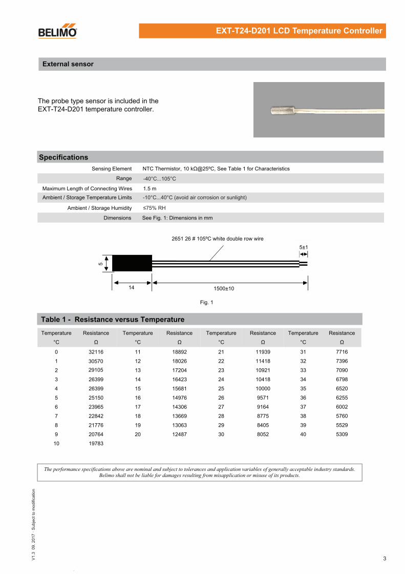
External sensor
The performance specifications above are nominal and subject to tolerances and application variables of generally acceptable industry standards. Belimo shall not be liable for damages resulting from misapplication or misuse of its products.
Table 1 - Resistance versus Temperature
The probe type sensor is included in the EXT-T24-D201 temperature controller.
SpecificationsSensing Element NTC Thermistor, 10 kΩ@25ºC, See Table 1 for Characteristics
Range
Maximum Length of Connecting Wires 1.5 m
Ambient / Storage Temperature Limits -10°C...40°C (avoid air corrosion or sunlight)
Dimensions See Fig. 1: Dimensions in mm
Temperature
°C
Resistance
Ω
Temperature
°C
Resistance
Ω
Temperature
°C
Resistance
Ω
0
1
2
3
4
5
6
7
8
9
10
32116
26399
26399
25150
23965
22842
21776
20764
19783
21
22
23
24
25
26
27
28
29
30
11939
11418
10921
10418
10000
9571
9164
8775
8405
8052
31
32
33
34
35
36
37
38
39
40
7716
7396
7090
6798
6520
6255
6002
5760
5529
5309
Temperature
°C
11
12
13
14
15
16
17
18
19
20
Resistance
Ω
18892
18026
17204
16423
15681
14976
14306
13669
13063
12487
-40°C...105°C
Ambient / Storage Humidity ≤75% RH
3057029105
Fig. 1
2651 26 # 105ºC white double row wire
14
5
1500±10
5±1


![DNV-OS-D201: Electrical Installations - Rules and · PDF fileDNV-OS-D201 Electrical Installations OCTOBER 2013 ... [1.2.1]: The option with only one electrical propulsion motor with](https://img.pdfslide.us/doc/110x75/5aaf36eb7f8b9adb688d5d70/dnv-os-d201-electrical-installations-rules-and-electrical-installations-october.jpg)