Embed Size (px)
Citation preview

ExSite “Sharing of Best Practices”
The following illustrations of system interconnections are provided only as a guideline.
Actual connections are dictated by local authorities and the A&E specifications of the site.
Pelco makes no recommendations on the connection of this system .
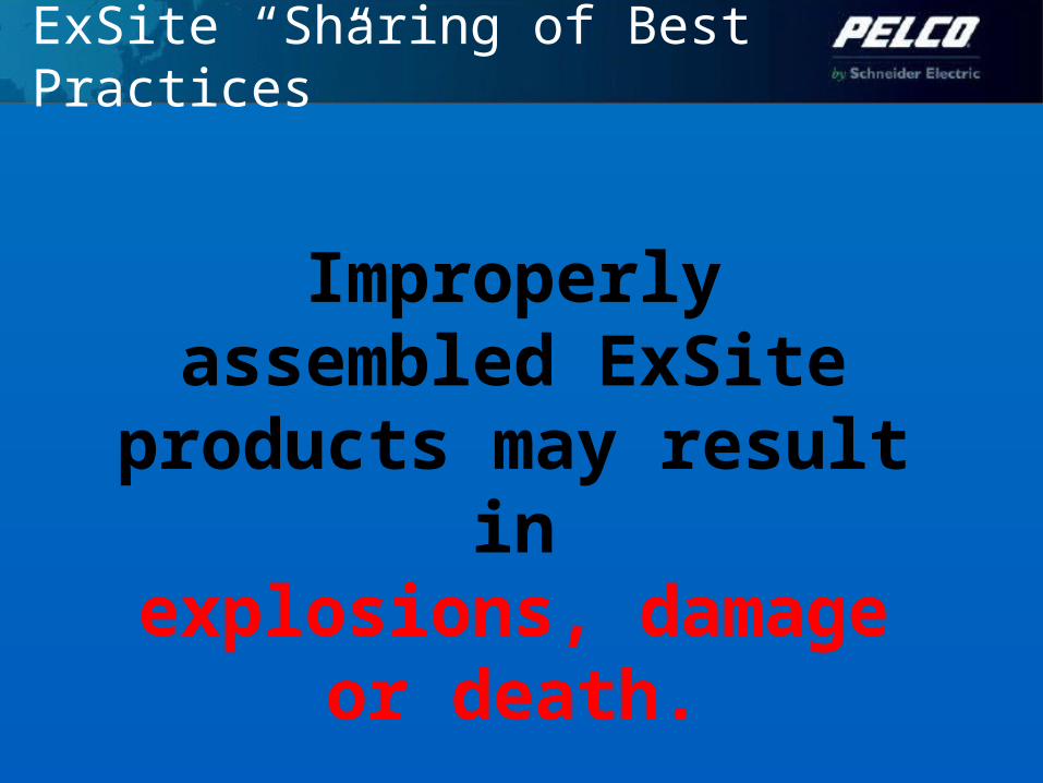
ExSite “Sharing of Best Practices”
Improperly assembled ExSite products may result
inexplosions, damage or
death.

ExSite “Sharing of Best Practices”
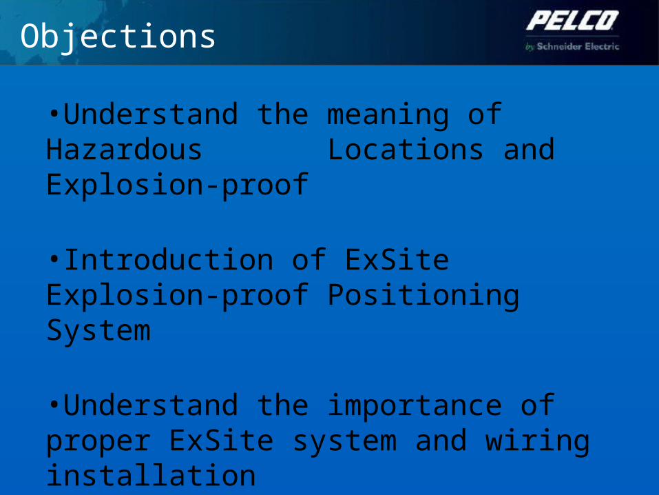
Objections
•Understand the meaning of Hazardous Locations and Explosion-proof
•Introduction of ExSite Explosion-proof Positioning System
•Understand the importance of proper ExSite system and wiring installation

General Overview
1. What is a flame path?A flame path is an opening that can be traced from inside the unit to the outside atmosphere.
2. Why is a flame path a special feature?A flame path is designed so that if a spark or explosion happened on the inside of the camera , the precision fit between parts would force it to be extinguished before reaching the outside atmosphere.

ExSite “Sharing of Best Practices”
Not gas-tight but strong enough to contain an explosion and prevent the escape of flame or heat that could ignite surrounding atmospheres

Result of Explosion
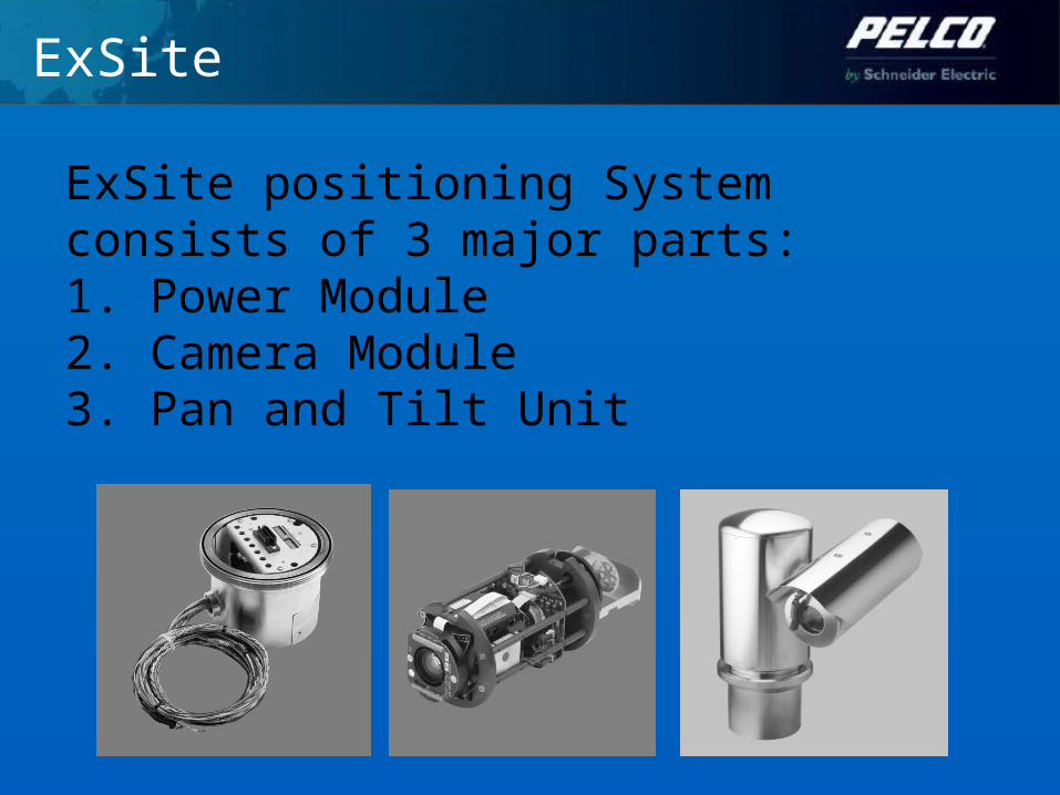
ExSite
ExSite positioning System consists of 3 major parts:1. Power Module2. Camera Module3. Pan and Tilt Unit
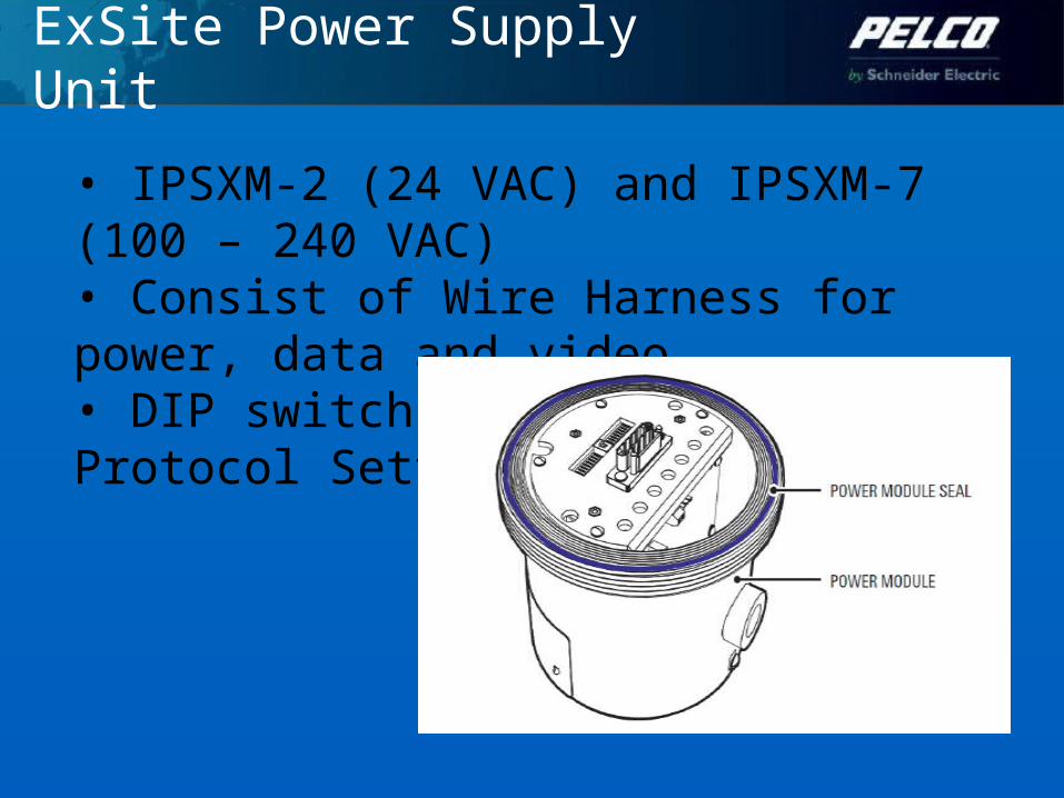
ExSite Power Supply Unit
• IPSXM-2 (24 VAC) and IPSXM-7 (100 – 240 VAC)• Consist of Wire Harness for power, data and video• DIP switch for Protocol Setting
ExSite Power Supply Unit
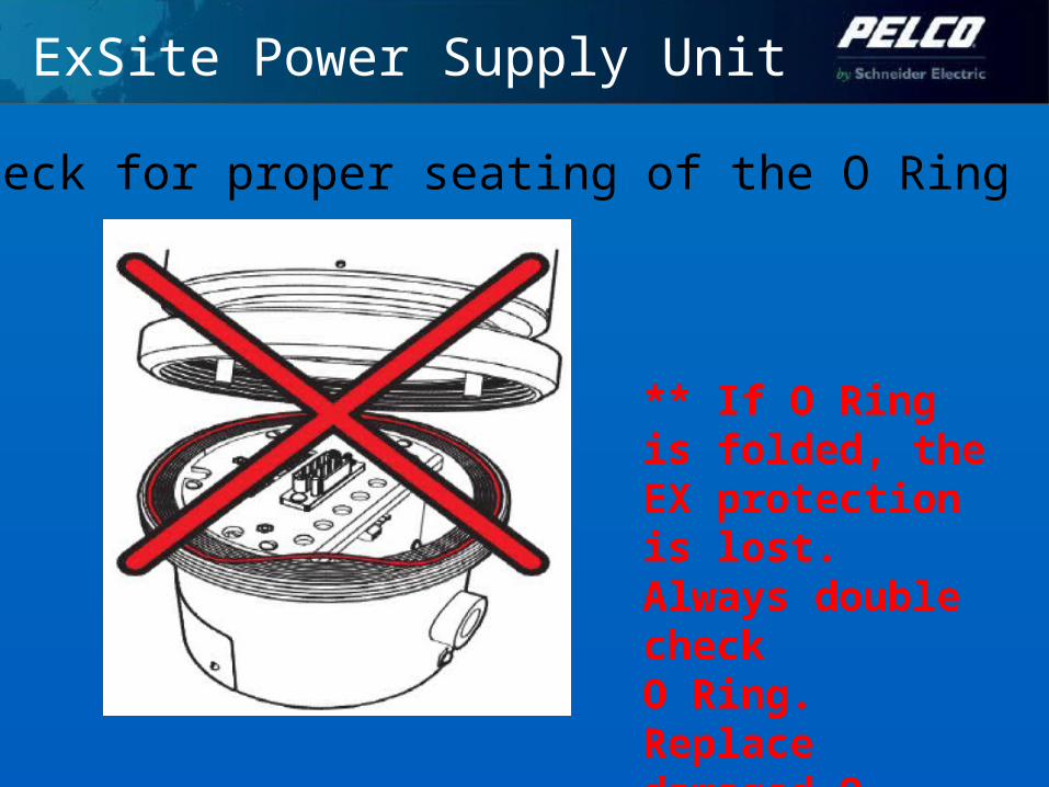
Check for proper seating of the O Ring
** If O Ring is folded, the EX protection is lost.Always double checkO Ring. Replacedamaged O-rings.

ExSite Power Supply Unit
• Total weight of the Pan &Tilt Unit is 32kg• Do not damage the power module grooves• Avoid thread damage (EX protection is lost) and please do not apply any silicon solution

Specific Codes
Wiring Installation for ExSite must bebased on local codes or specificindustry requirements.
General wiring installation code/requirement:IEC, CENELEC,NEC, Marine, Oil & Gas.

ExSite Installation Kits
Supplied with ExSite
Qty Description1 Nipple1 Sealing fitting
User-Supplied Parts
Qty Description1 Nipple1 Sealing fitting1 Sealing Compound1 Fiber filler1 Explosion Nipple1 Compression Gland
Introduction of seal fittingConduit seals prevent explosions from spreading through conduit systems and igniting outside atmospheres. When properly installed and filled with a UL-listed sealing compound, they prevent the passage of gases, vapors, or flames from spreading from a hazardous location to a nonhazardous location. This limits explosions to the EX rated enclosure.
Prevent precompression, or “pressure piling,” in conduit systems.
EX rated compression cables and compression glands are an alternatives to sealed conduit installations. This presentation will focus on the more traditional conduit installation.
Introduction of seal fitting
The maximum ambient temperature range is -76°F to 140°F (-60°C to 60°C).
Installation should be done only by qualified personnel and conform to all local codes.
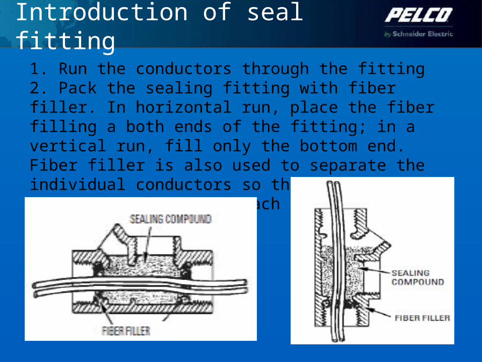
Introduction of seal fitting
1. Run the conductors through the fitting2. Pack the sealing fitting with fiber filler. In horizontal run, place the fiber filling a both ends of the fitting; in a vertical run, fill only the bottom end. Fiber filler is also used to separate the individual conductors so that the sealing compound seals around each conductor.
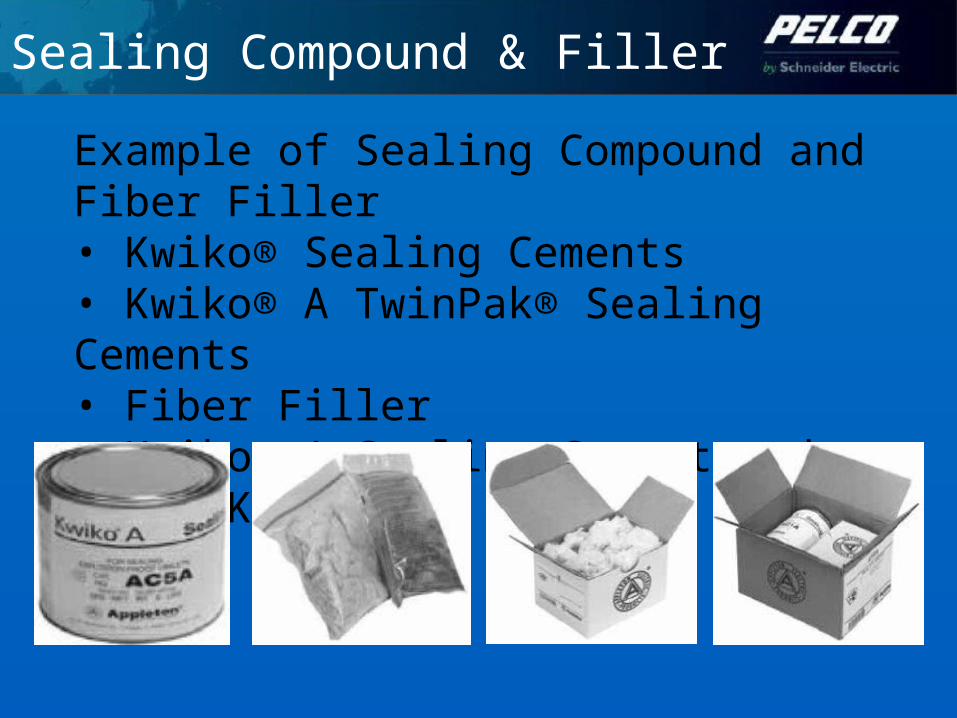
Sealing Compound & Filler
Example of Sealing Compound and Fiber Filler• Kwiko® Sealing Cements• Kwiko® A TwinPak® Sealing Cements• Fiber Filler• Kwiko® A Sealing Cement and Fiber Kits
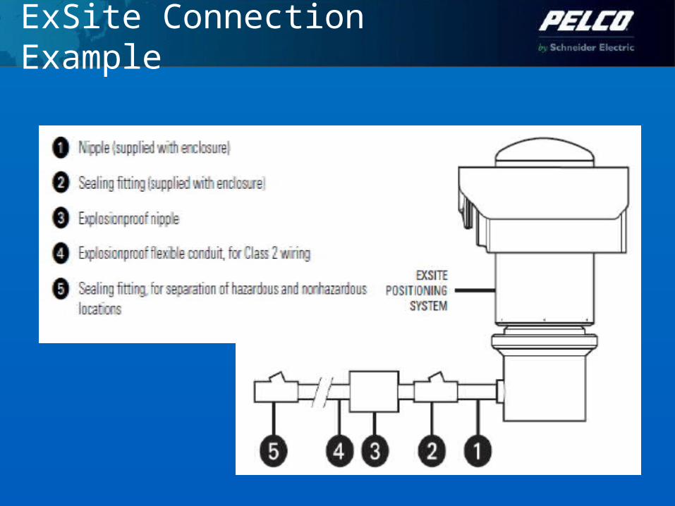
ExSite Connection Example

ExSite Installation Guideline
• Indirect cable entry
• Increased Safety (Ex e)
• 1.6 meter length potted cable (factory sealed)

IOP Module
• 22X Color and 23X Day/Night (PAL/NTSC)• Standard or With Wiper

IOP Enclosure
To access to the IOP compartment, you need to loosen set screw and remove the back cover
Tool Required:1.5 mm Allen wrenchSpanner wrench
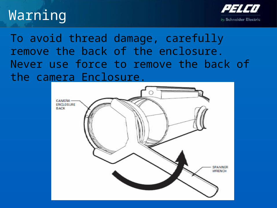
Warning
To avoid thread damage, carefully remove the back of the enclosure. Never use force to remove the back of the camera Enclosure.

IOP Enclosure
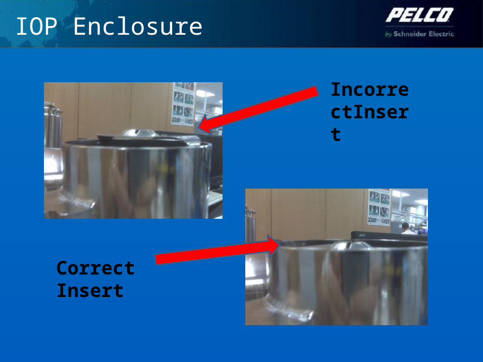
IOP Enclosure
IncorrectInsert
Correct Insert
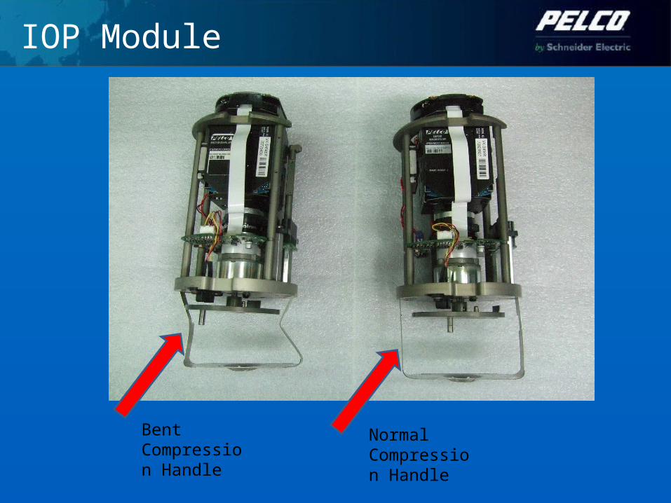
IOP Module
Bent Compression Handle
Normal Compression Handle
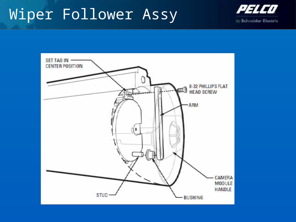
Wiper Follower Assy

IOP Enclosure
Caution• Be careful when install the back cap to theenclosure, never force it to avoiddamaging the thread (EX protection islost)• Please do not apply silicon solution on thethread• There should be no gap between the backcap and the enclosure
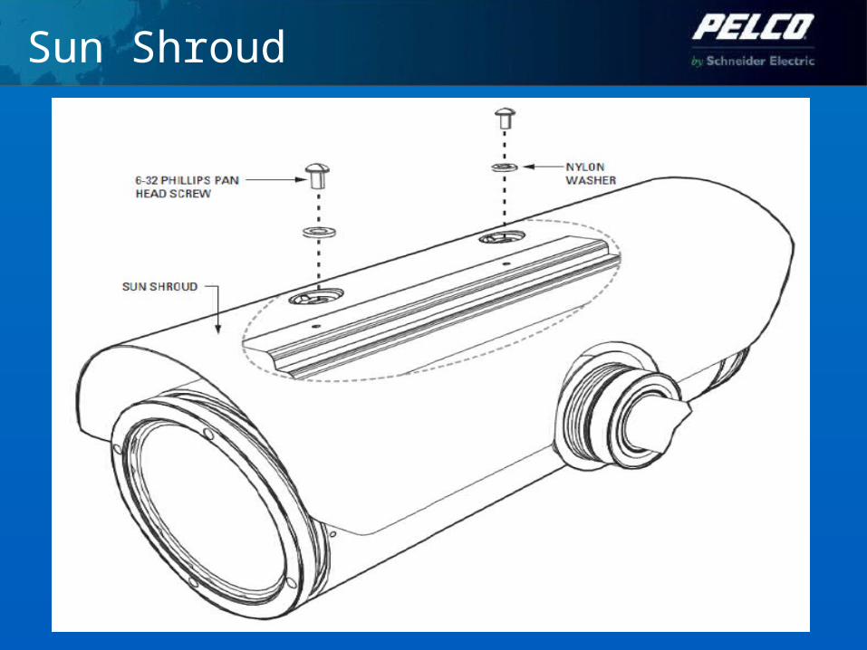
Sun Shroud

ExSite “sharing of best practices”
• Please do not try to open the:
1.Front Window of the Camera Enclosure2.Top cover of the Pan and Tilt Enclosure3.Please do not use inappropriate tools during installation
Only trained and certified service personnel should perform this task.

ExSite “sharing of best practices”
Improper & Incorrect installation.

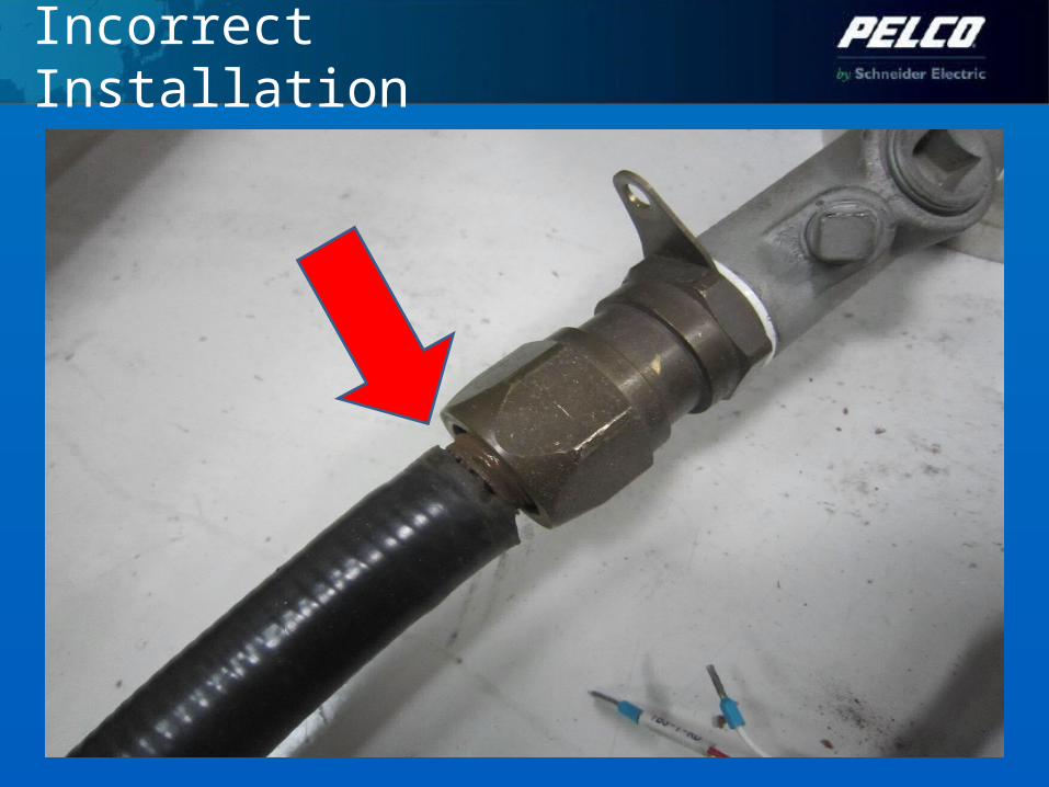
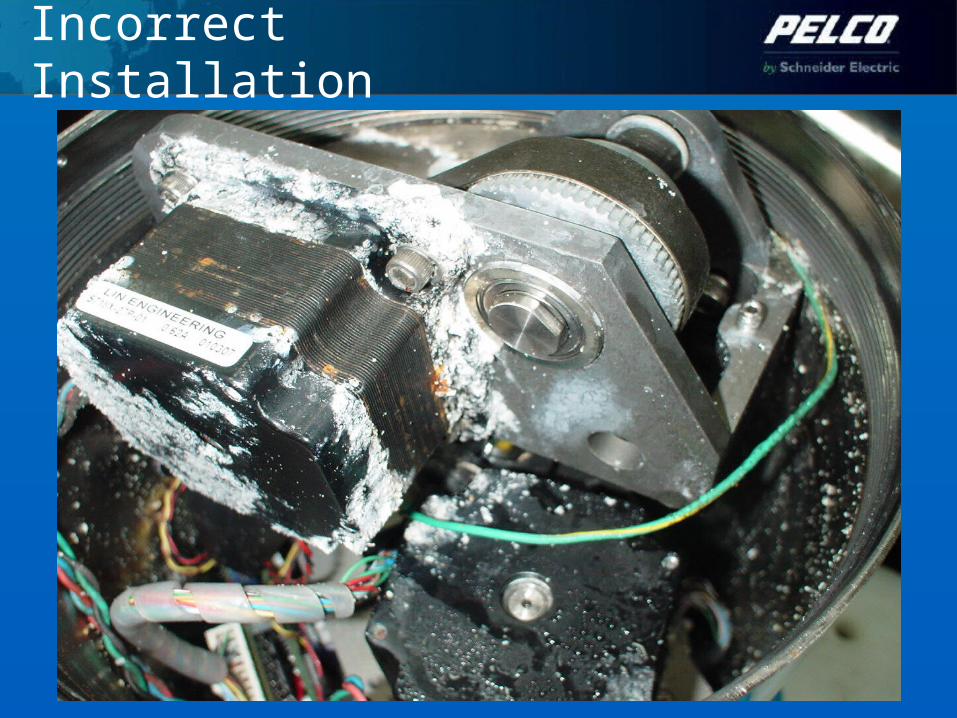
Incorrect Installation
Installed without sealing compound & individual wires not properly separated

Incorrect Installation
Improper curing of sealing compound and individual wires not properly separated. No wire twisting should occur.
Incorrect Installation

Incorrect Installation
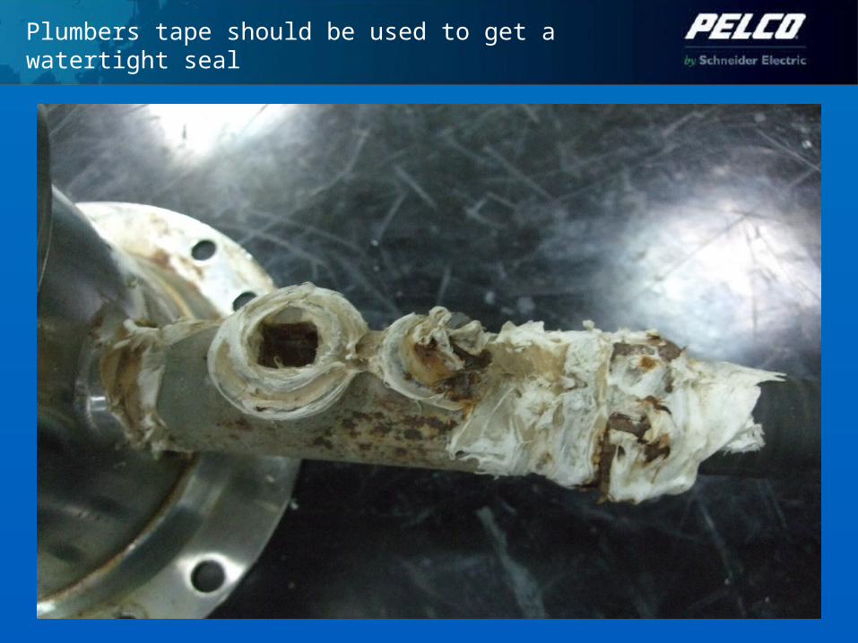
Plumbers tape should be used to get a watertight seal

Plumbers tape should be used to get a watertight seal

Incorrect Installation
Enclosure back cover and front window opening cover with silicon
corrosion and rusty found on the enclosure , resulted difficulty for repair and mainteance.
Incorrect Installation
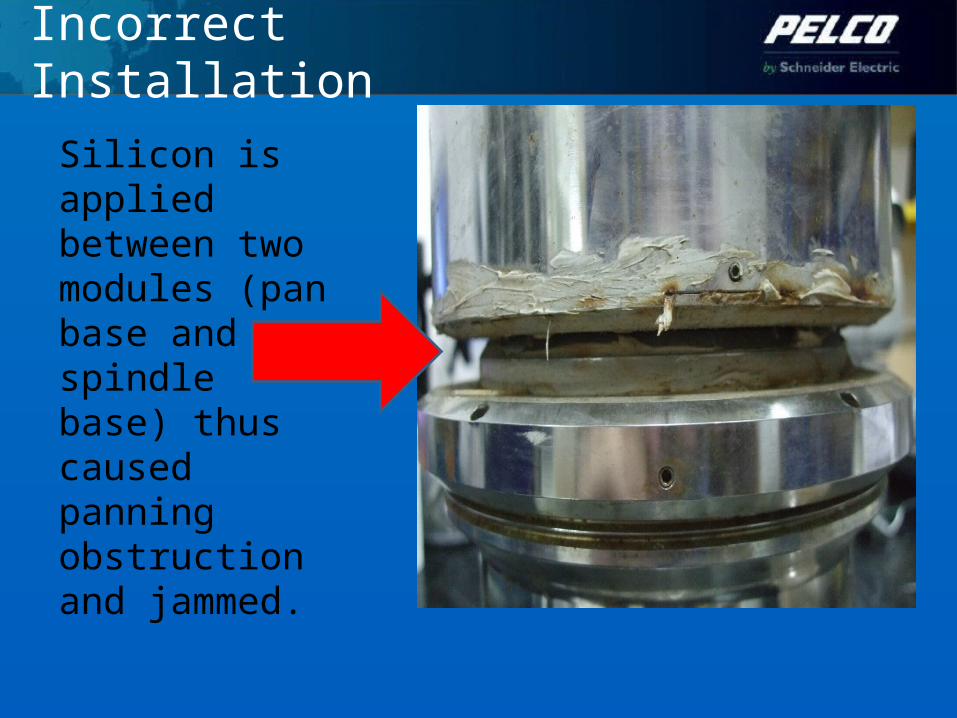
Silicon is applied between two modules (pan base and spindle base) thus caused panning obstruction and jammed.
Incorrect Installation
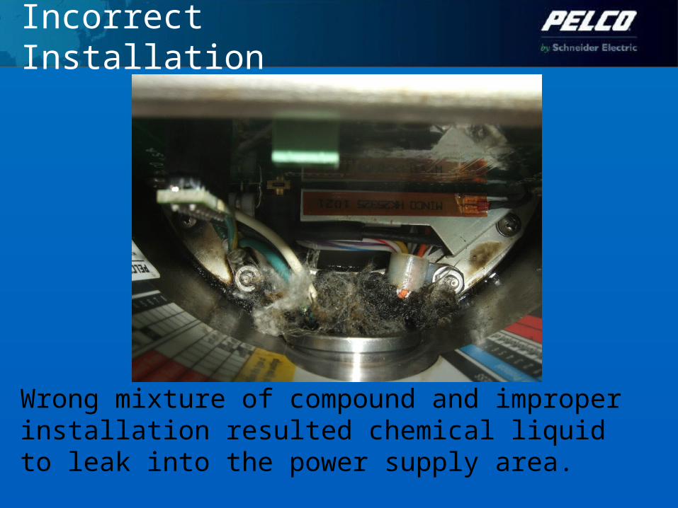
Wrong mixture of compound and improper installation resulted chemical liquid to leak into the power supply area.
Incorrect Installation
ExSite Installation Guideline
Questions?
Thank you!