Embed Size (px)
Citation preview
Express Service ManualCentral Systems
600REY, 600WCY, 1100WCX, 2000REY, 2000WCY
You have just purchased the best spray washer on the market today. It incorporates the very latest in technological advances. To assure you the best and safest performance as well as longest equipment life, please read the enclosed information.
After reading the material in this manual, should you have a service problem or need help, please call our toll free number 1-800-548-3373 or(479) 636-5776.
TERMS: All parts will be shipped with check in advance or C.O.D. Commercial accounts are allowed 15 day terms from date on invoice with approved credit.
FREIGHT: All freight will be paid by the customer. Special consideration will be given to items under warranty coverage.
NOTE: Specifications found in this manual subject to change without notice.FOR COMMERCIAL USE ONLY
IMPORTANT DOCUMENT - DO NOT DISCARDDate PurchasedSerial NumberModel Number
spraymastertech.com
2
SMT WARRANTY – LIMITED Effective November 1, 2008
PARTS -SMT warrants parts for wall mounted and rack mounted 600 series and 2000 series machine to be free from defects in material or workmanship for a period of 2 years from the date of purchase from date of shipment from factory (if proof of purchase is missing) to the original purchaser excluding items listed below.
SMT warrants parts for all other machines, wall mounted 1100 series machines and all portable machines to be free from defects in material or workmanship for a period of 1 year from the date of purchase (from date of shipment from factory if proof of purchase is missing) to the original purchaser excluding items listed below. This warranty is limited to repairing or replacing products to the original purchaser, which manufacturer’s investigation shows were defective at the time of shipment by the manufacturer. All products subject to this warranty shall be returned F.O.B. Spray Master Technologies - Rogers, Arkansas for examination, repair or replacement.
The warranty set forth herein is in lieu of all other warranties, expressed or implied, including without limitation any warranties of merchantability or fitness for a particular purpose and all such warranties are hereby disclaimed and excluded by the manufacturer. The manufacturer shall not be liable for any further loss, damages, or expenses, including incidental or consequential damages, directly or indirectly arising from the sale or use of this product.
ITEMS VOIDING WARRANTY - This warranty is subject to the following conditions and limitations. The following voids all warranty claims on Spray Master Technologies products: Abuse, misuse, using exces sive hot water temperatures - exceeding 120 degrees Fahrenheit (49 degrees Celsius), hard water condi tions, using bleach as an injected chemical, failures caused by incorrect installation or failure to correctly wire the system at the electrical source.
EXCLUDED ITEMS - The following items are excluded: SPRAY GUNS, WANDS, HOSES, NOZZLES, HUMMER JET SR. & JR. CASTERS AND HANDLES. These items are covered by the above warranty for 90 days from the date of purchase for defects in materials or workmanship.
LABOR - to repair or replace defective components shall be covered for a period of 1 year from date of purchase (90 days on excluded items), proof of purchase is required.
www.spraymastertech.com Phone: (479) 636-5776 • Fax: (479) 636-3245 • 115 E. Linden • Rogers, Arkansas 72756 USA
SMT-WARRANTY-CS-102808-EN Specifications are subject to change without notice Printed in the U.S.A.
Returned Goods PolicyAny item returned for warranty consideration or for credit must have a RETURN AUTHORIZATION NUMBER. Call our Customer Service Department and discuss the nature of your request. Please note that all items returned must be returned F.O.B. Rogers, Arkansas. No collect or C.O.D. shipments will be accepted unless prior arrangements with our Customer Service Department have been made. A restocking fee may be applied to items for credit that are not under warranty. To reach our Customer Service Department call (800) 548-3373 or (479) 636-5776, or write to Spray Master Technologies, 115 E. Linden Street, Rogers, Arkansas 72756.
ReceivingDamage: Report any damage to the shipping carton or contents to the freight carrier. File a claim with the carrier within 10 days if damage is evident. The manufacturer is not responsible for damage to the equipment caused by the freight carrier.
Package Contents: Carefully check the contents of the shipping cartons to ensure the contents agree with the packing list. If items are missing or if you have any questions, please call our customer service department at (800) 548-3373 or (479) 636-5776.
Receiving 2
Returned Goods Policy 2
Warranty 2
Service Requirements 3
Service 3
Model Identification 3
Express Service Program 4
Theory of Operation 4
Mechanical 4
Electrical 5
Central System Diagnostic Chart 8-10
Parts Breakdown / Parts List 11
600REY/WCY 11
1100WCX 11
2000REY/WCY 12
Remote Stations 13-14
Spray Guns 15
Table of Contents
3
If a problem occurs, please refer to the “Diagnostic and Maintenance Chart” in the product Service Manual. Also, refer to the CAT Pumps Service Manual provided with your system. If the problem is not resolved, then please call our toll free customer service number:
1-800-548-3373 or (479) 636-5776
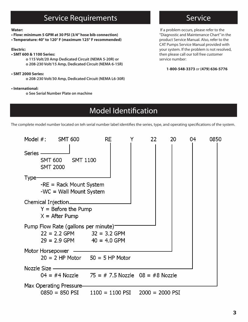
The complete model number located on teh serial number label identifies the series, type, and operating specifications of the system.
Service RequirementsWater:• Flow: minimum 5 GPM at 30 PSI (3/4” hose bib connection)• Temperature: 40° to 120° F (maximum 125° F recommended)
Electric:• SMT 600 & 1100 Series: o 115 Volt/20 Amp Dedicated Circuit (NEMA 5-20R) or o 208-230 Volt/15 Amp, Dedicated Circuit (NEMA 6-15R)
• SMT 2000 Series: o 208-230 Volt/30 Amp, Dedicated Circuit (NEMA L6-30R)
• International: o See Serial Number Plate on machine
Model Identification
Service
4
Express Service Program
If you have a problem, we can solve it QUICKLY and EFFICIENTLY. Your Spray Master Technologies pressure cleaning system has been designed for rapid and easy repairs. Some, you can do, others we will do.
With the “EXPRESS SERVICE” program, your machine has been divided into six major component groups. These groups consist of:
• Group #1: Pump, Unloader, Injector, In/out hoses• Group #2: Motor, Switch, and Cord Set• Group #3: Float Tank Assembly• Group #4: High Pressure Hose• Group #5: Spray Gun Assembly• Group #6: Accessories and Miscellaneous Parts
Like circuit boards on a computer, these groups can be exchanged as a complete unit. The advantage is your savings in time and money.
With a toll free call to experienced service technicians at Spray Master Technologies, the problem can usually be diagnosed to one of the six component groups by answering a few questions.
The person doing the parts replacement doesn’t need to have any equipment knowledge. He/she need only be able to loosen and tighten a few bolts. The “Express Service” exchange program eliminates having an inexperienced person trying to repair a complicated part.
If you do your own “GROUP” exchange, you won’t be paying for those high labor rates and expensive service calls. With a few basic tools, the defective component group can be removed and replaced or sent to the factory for repair by a qualified technician with minimum downtime. To further expedite the repair, either you or your dealer can stock spare components “groups”. However, with express mail services, rarely does it take more than 48 hours to receive a component. This is usually faster and less expensive than many service companies can make a service call.
The enclosed information shows all components groups and accessories. Our trained personnel are ready to help. If you need service, try our “EXPRESS SERVICE” plan. It will save you time and money.
General Principle of Pressure Washers.Pressure in Spray Master Technologies and most other pressure washers is produced by forcing a fixed gallons per minute (GPM) volume of water through an orifice. The fixed volume of water is provided by a positive displacement pump, which will produce a specific GPM of water flow regardless of the operating pressure. The orifice is a part of the nozzle on the end of the spray gun. The volume of water and the orifice size can be varied, resulting in a corresponding change in the operating pressure of the system. The following paragraphs explain the function of system components and flow sequence in SMT pressure cleaning systems. This brief theory of operation will provide a service tech with information necessary to quickly diagnose and correct any malfunction of the system.
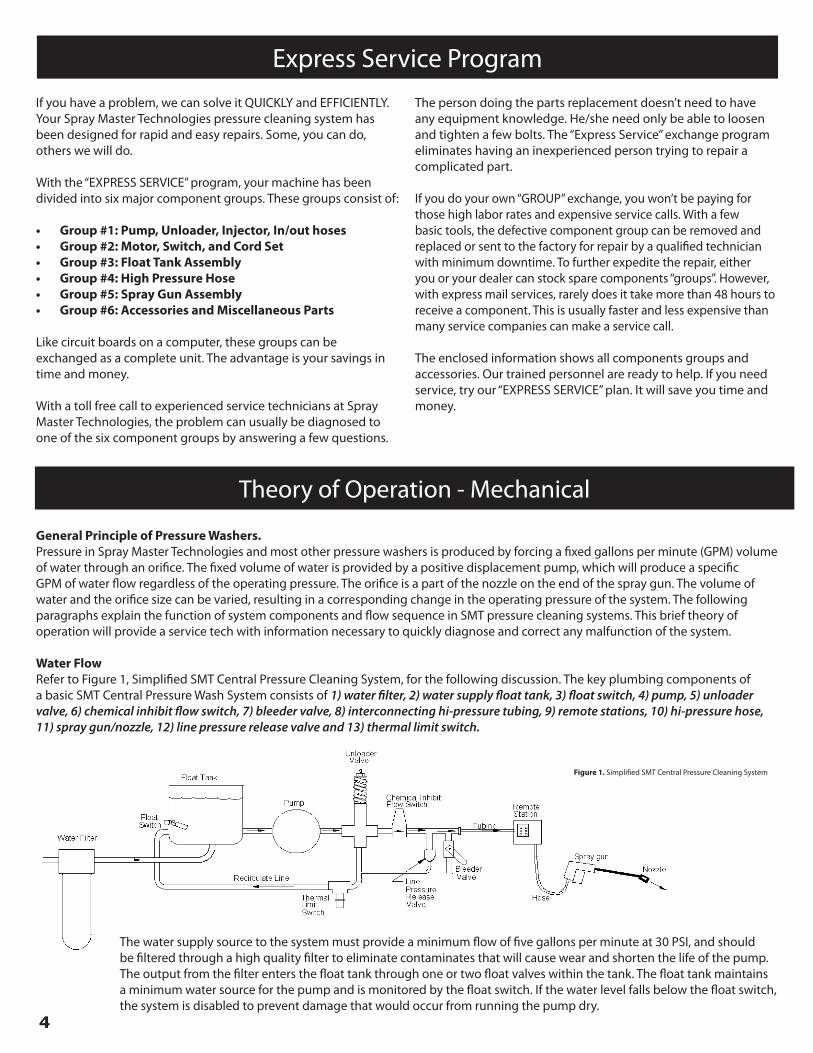
Water FlowRefer to Figure 1, Simplified SMT Central Pressure Cleaning System, for the following discussion. The key plumbing components of a basic SMT Central Pressure Wash System consists of 1) water filter, 2) water supply float tank, 3) float switch, 4) pump, 5) unloader valve, 6) chemical inhibit flow switch, 7) bleeder valve, 8) interconnecting hi-pressure tubing, 9) remote stations, 10) hi-pressure hose, 11) spray gun/nozzle, 12) line pressure release valve and 13) thermal limit switch.
Theory of Operation - Mechanical
Figure 1. Simplified SMT Central Pressure Cleaning System
The water supply source to the system must provide a minimum flow of five gallons per minute at 30 PSI, and should be filtered through a high quality filter to eliminate contaminates that will cause wear and shorten the life of the pump. The output from the filter enters the float tank through one or two float valves within the tank. The float tank maintains a minimum water source for the pump and is monitored by the float switch. If the water level falls below the float switch, the system is disabled to prevent damage that would occur from running the pump dry.
5
Theory of Operation - Electrical
When the pump is in operation, it draws water from the float tank and pumps it out to the unloader assembly. The unloader assembly directs the water through the system to the spray gun if the spray gun is open, or it diverts the water back to the float tank, through there-circulate path, if the spray gun is closed. In addition, the unloader is used to set the maximum operating pressure of the system.From the high-pressure output of the unloader, the water flows through the chemical inhibit flow-switch, past the bleeder valve assembly to the interconnecting high-pressure tubing and out to all the remote stations. The pump can service up to ten remote stations. Each remote station is equipped with a quick-connect port for connection of a high-pressure hose.
From the remote station, the water flows through the hose to the spray gun. The water passes through the spray gun when the gun-trigger is activated and flows to the nozzle at the end of the lance. As the water is forced through the orifice in the nozzle, pressure builds within the system. The size of the orifice in the nozzle determines the maximum pressure that can be achieved with the flow rate provided by the pump. The smaller the orifice, the higher the pressure. Most SMT systems are equipped with a dual nozzle selector and two nozzles. The nozzle with the small orifice will produce high pressure, while the nozzle with the large orifice produces low pressure.
Note: Selecting the correct nozzle size for the system is critical to the correct operation and cleaning effectiveness. A nozzle with too small an orifice will result in less water flow and reduced cleaning effectiveness and may result in too high pressure, overloading the motor. A nozzle too large will result in lower pressure and reduced cleaning effectiveness.
During operation, when the spray gun trigger is released, pressure builds in the system until it overcomes the tension on the unloader spring and activates the unloader assembly. When the unloader assembly is activated, it locks pressure into the output line to the spray gun and redirects the flow of water, at low pressure, through the recirculate line back to the system float tank. Recirculation will continue until the line pressure is reduced by reactivating the trigger on the spray gun. This unloading feature prolongs the life of the pump and motor by removing the strain on the pump and motor during periods when the spray gun is inactive.
Electrical RequirementsThe electrical requirements for the SMT Central Pressure Cleaning system depends on the SMT model installed. Regardless of model, all central systems must be powered by a dedicated circuit with a Ground Fault Circuit Interrupter (GFCI) breaker in the main breakerpanel and a service disconnect at the pump. Electrical service requirements are:
• 2000REY/WCY: 208/230 Volt, 30 Amp• 600REY/WCY: 208/230 Volt, 15 Amp 115 Volt, 20 Amp (optional)• 1100WCX: 208/230 Volt, 15 Amp 115 Volt, 20 Amp (optional)
Line voltage to the system is supplied from the service disconnect into the SMT Master Control Panel (MCP) to the input side of contactor K3.
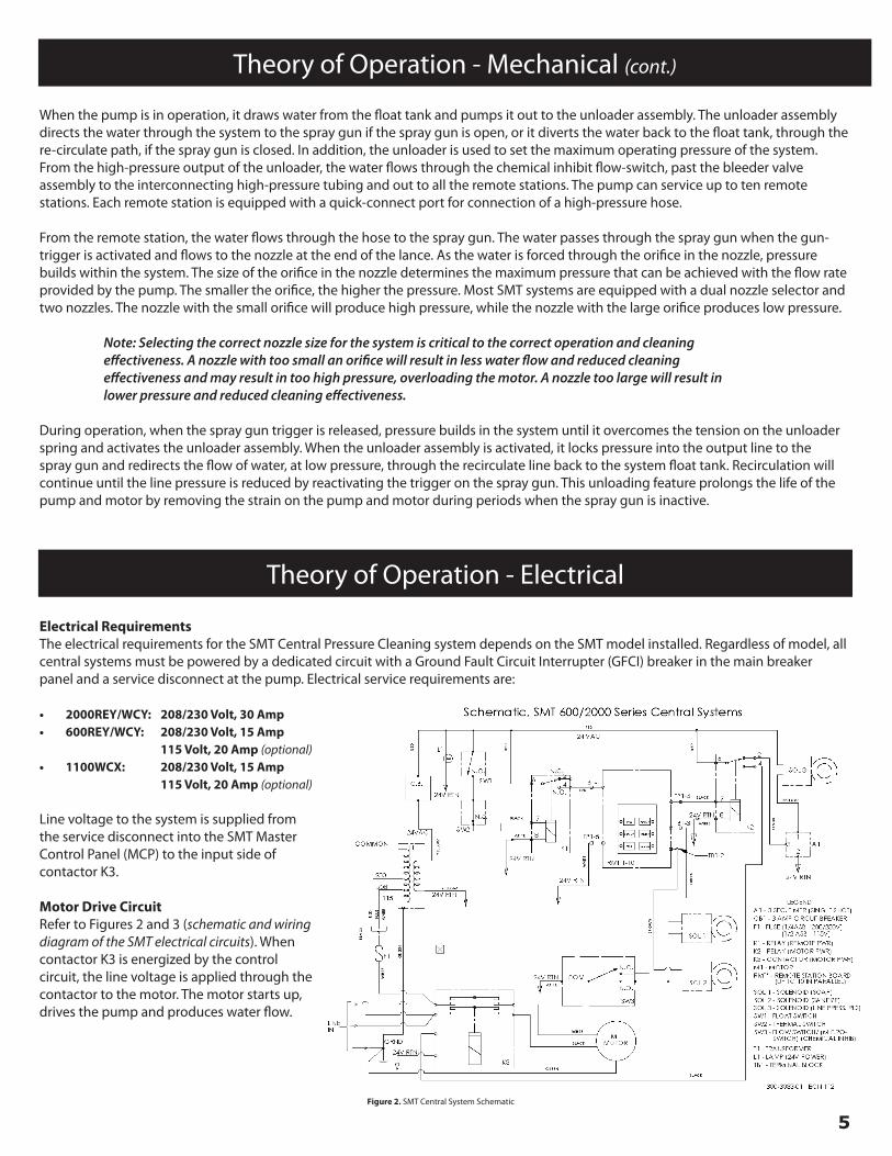
Motor Drive CircuitRefer to Figures 2 and 3 (schematic and wiring diagram of the SMT electrical circuits). When contactor K3 is energized by the control circuit, the line voltage is applied through the contactor to the motor. The motor starts up, drives the pump and produces water flow.
Theory of Operation - Mechanical (cont.)
6
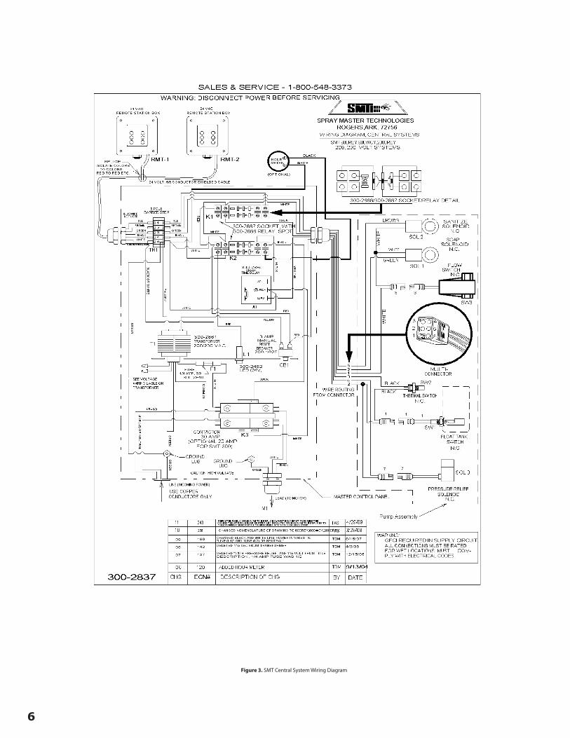
Figure 3. SMT Central System Wiring Diagram
7
Theory of Operation - Electrical (cont.)
Control CircuitsControl circuits within SMT central systems are 24 Volt AC low voltage. The control circuits include the 24V AC power circuit, water condition sensors circuit, remote stations circuit, motor control circuit, chemical control circuits and the line pressure release circuit.
24V AC power circuit provides low voltage AC for all control circuits. Line voltage to the system is picked off of the contactor line terminals and applied through fuse (FI) to the multi-tap input of the 24V transformer (T1). F1 requires a ¼ amp slow-blow fuse for 208and 230 volt inputs, or ½ amp slow-blow fuse for 115 volt input. Voltage is applied to Transformer (T1) through one of three leads of the primary winding. The multi-tap primary leads permit system operation on 115, 208 or 230 volts AC. The 24volt output is routedthrough 3 amp circuit breaker (CB1) to the 24V AC Power indicator (LI) and the rest of the control circuits. Current flow through all circuits returns to the transformer through the 24V AC return line. The 24V AC is connected to Float Switch (SW1), Remote Station Power Relay (K1), Motor Drive Relay (K2), and to the Line Pressure Release Solenoid (SOL 3).
Water condition sensor circuits provide protection to the pump when adverse water conditions exist. The sensors will remove power from the remote stations when the water supply level is too low or water temperature exceeds 140° F. Float Switch (SW1) is closedwhen the water level in the float tank is above the minimum operating level for the pump, completing the circuit through Thermal Limit Switch (SW2) which will energize Relay (K1) and apply power to all Remote Stations (RMT-*). Thermal Limit Switch (SW2) is normallyclosed. When water temperature within the system exceeds 140°F, Thermal Limit Switch (SW2) will open and remove power from the remote stations.
Remote station control circuits facilitate remote operation of the pump and consists of up to ten remote stations (TB1 – TB10), five conductor shielded cable and 5-pole Terminal Block (TB1). All signals to and from the remote stations enter and exit the Master Control Panel through terminal block (TB1). Signal lines to/from the remote are:
• Red wire – 24V AC power (out to remote station)• White wire – 24V AC return (out to remote station)• Black wire – 24V AC motor control signal (in from remote station)• Green wire – 24V AC soap control signal (in from remote station)• Brown wire – 24V AC sanitizer control signal (in from remote station)
All remote stations are connected in parallel through the 5 conductor shielded cable. Each remote is spliced into the main trunk of the control cable by color matching and connecting the wires at each splice.
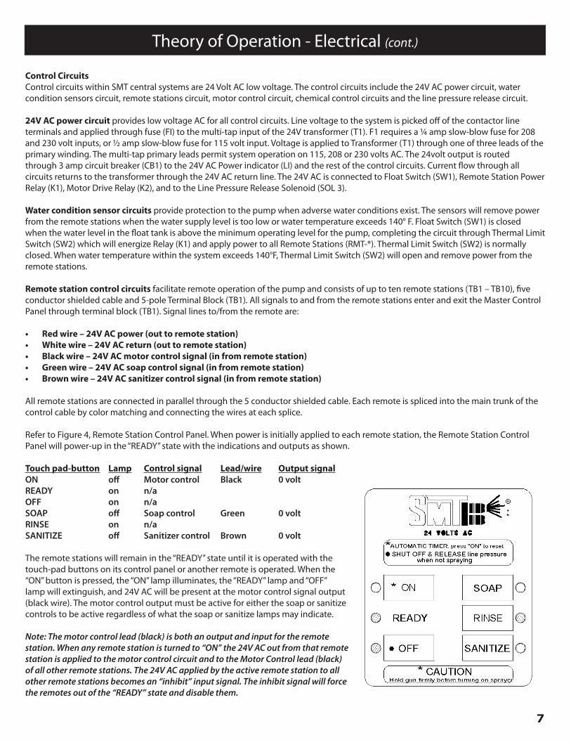
Refer to Figure 4, Remote Station Control Panel. When power is initially applied to each remote station, the Remote Station Control Panel will power-up in the “READY” state with the indications and outputs as shown.
Touch pad-button Lamp Control signal Lead/wire Output signalON off Motor control Black 0 voltREADY on n/aOFF on n/aSOAP off Soap control Green 0 voltRINSE on n/aSANITIZE off Sanitizer control Brown 0 volt
The remote stations will remain in the “READY” state until it is operated with the touch-pad buttons on its control panel or another remote is operated. When the “ON” button is pressed, the “ON” lamp illuminates, the “READY” lamp and “OFF” lamp will extinguish, and 24V AC will be present at the motor control signal output (black wire). The motor control output must be active for either the soap or sanitize controls to be active regardless of what the soap or sanitize lamps may indicate.
Note: The motor control lead (black) is both an output and input for the remote station. When any remote station is turned to “ON” the 24V AC out from that remote station is applied to the motor control circuit and to the Motor Control lead (black) of all other remote stations. The 24V AC applied by the active remote station to all other remote stations becomes an “inhibit” input signal. The inhibit signal will force the remotes out of the “READY” state and disable them.
8
Theory of Operation - Electrical (cont.)
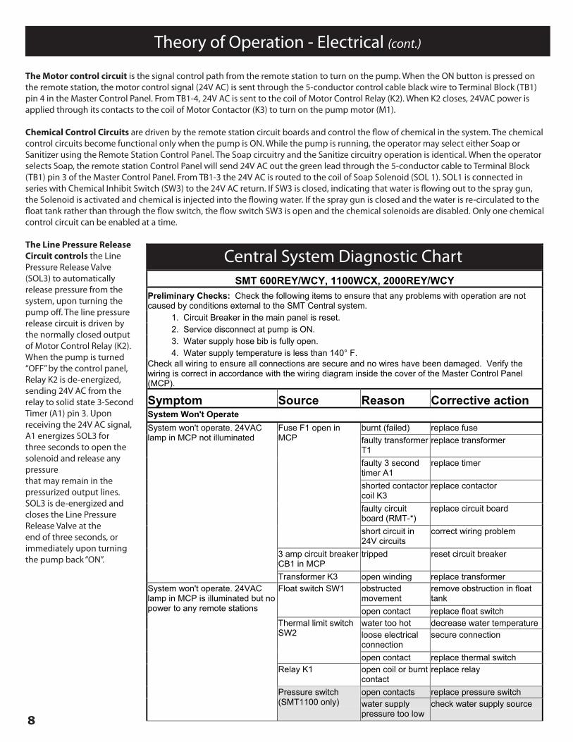
The Motor control circuit is the signal control path from the remote station to turn on the pump. When the ON button is pressed on the remote station, the motor control signal (24V AC) is sent through the 5-conductor control cable black wire to Terminal Block (TB1) pin 4 in the Master Control Panel. From TB1-4, 24V AC is sent to the coil of Motor Control Relay (K2). When K2 closes, 24VAC power is applied through its contacts to the coil of Motor Contactor (K3) to turn on the pump motor (M1).
Chemical Control Circuits are driven by the remote station circuit boards and control the flow of chemical in the system. The chemical control circuits become functional only when the pump is ON. While the pump is running, the operator may select either Soap or Sanitizer using the Remote Station Control Panel. The Soap circuitry and the Sanitize circuitry operation is identical. When the operator selects Soap, the remote station Control Panel will send 24V AC out the green lead through the 5-conductor cable to Terminal Block (TB1) pin 3 of the Master Control Panel. From TB1-3 the 24V AC is routed to the coil of Soap Solenoid (SOL 1). SOL1 is connected in series with Chemical Inhibit Switch (SW3) to the 24V AC return. If SW3 is closed, indicating that water is flowing out to the spray gun, the Solenoid is activated and chemical is injected into the flowing water. If the spray gun is closed and the water is re-circulated to the float tank rather than through the flow switch, the flow switch SW3 is open and the chemical solenoids are disabled. Only one chemical control circuit can be enabled at a time.
The Line Pressure Release Circuit controls the Line Pressure Release Valve (SOL3) to automatically release pressure from the system, upon turning the pump off. The line pressure release circuit is driven by the normally closed output of Motor Control Relay (K2).When the pump is turned “OFF” by the control panel, Relay K2 is de-energized, sending 24V AC from the relay to solid state 3-Second Timer (A1) pin 3. Upon receiving the 24V AC signal, A1 energizes SOL3 for three seconds to open the solenoid and release any pressurethat may remain in the pressurized output lines. SOL3 is de-energized and closes the Line Pressure Release Valve at the end of three seconds, or immediately upon turning the pump back “ON”.
13
Central System Diagnostic Chart SMT 600REY/WCY, 1100WCX, 2000REY/WCY
Preliminary Checks: Check the following items to ensure that any problems with operation are not caused by conditions external to the SMT Central system. 1. Circuit Breaker in the main panel is reset. 2. Service disconnect at pump is ON. 3. Water supply hose bib is fully open. 4. Water supply temperature is less than 140° F. Check all wiring to ensure all connections are secure and no wires have been damaged. Verify the wiring is correct in accordance with the wiring diagram inside the cover of the Master Control Panel (MCP).
Symptom Source Reason Corrective action System Won't Operate
burnt (failed) replace fuse faulty transformer T1
replace transformer
faulty 3 second timer A1
replace timer
shorted contactor coil K3
replace contactor
faulty circuit board (RMT-*)
replace circuit board
Fuse F1 open in MCP
short circuit in 24V circuits
correct wiring problem
3 amp circuit breaker CB1 in MCP
tripped reset circuit breaker
System won't operate. 24VAC lamp in MCP not illuminated
Transformer K3 open winding replace transformer obstructed movement
remove obstruction in float tank
Float switch SW1
open contact replace float switch water too hot decrease water temperatureloose electrical connection
secure connection Thermal limit switch SW2
open contact replace thermal switch Relay K1 open coil or burnt
contact replace relay
open contacts replace pressure switch
System won't operate. 24VAC lamp in MCP is illuminated but no power to any remote stations
Pressure switch (SMT1100 only) water supply
pressure too low check water supply source
9
Central System Diagnostic Chart
14
Remote Station circuit board RMT*
loose wires or defective board
secure wires or replace circuit board
Relay K2 open coil or burnt contact
replace relay
Contactor K3 open coil or burnt contact
replace contactor
thermal overload switch is tripped
reset or replace thermal overload switch
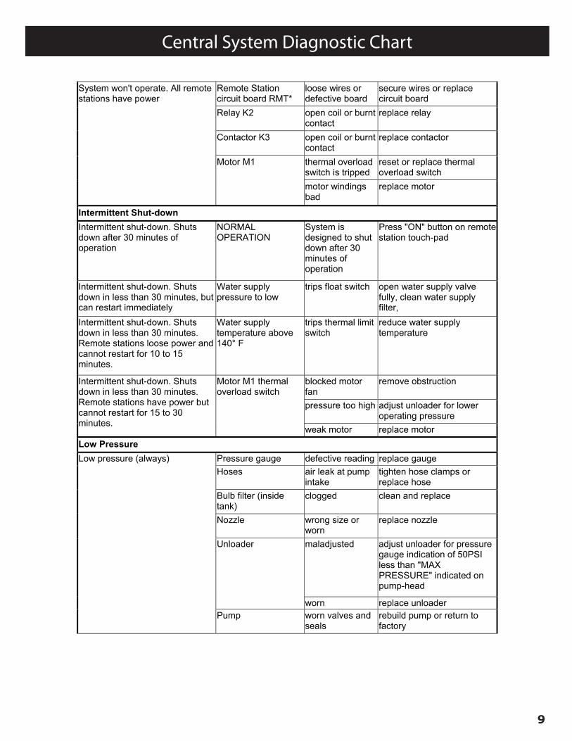
System won't operate. All remote stations have power
Motor M1
motor windings bad
replace motor
Intermittent Shut-down
Intermittent shut-down. Shuts down after 30 minutes of operation
NORMAL OPERATION
System is designed to shut down after 30 minutes of operation
Press "ON" button on remote station touch-pad
Intermittent shut-down. Shuts down in less than 30 minutes, but can restart immediately
Water supply pressure to low
trips float switch open water supply valve fully, clean water supply filter,
Intermittent shut-down. Shuts down in less than 30 minutes. Remote stations loose power and cannot restart for 10 to 15 minutes.
Water supply temperature above 140° F
trips thermal limit switch
reduce water supply temperature
blocked motor fan
remove obstruction
pressure too high adjust unloader for lower operating pressure
Intermittent shut-down. Shuts down in less than 30 minutes. Remote stations have power but cannot restart for 15 to 30 minutes.
Motor M1 thermal overload switch
weak motor replace motor Low Pressure
Pressure gauge defective reading replace gauge Hoses air leak at pump
intake tighten hose clamps or replace hose
Bulb filter (inside tank)
clogged clean and replace
Nozzle wrong size or worn
replace nozzle
maladjusted adjust unloader for pressure gauge indication of 50PSI less than "MAX PRESSURE" indicated on pump-head
Unloader
worn replace unloader
Low pressure (always)
Pump worn valves and seals
rebuild pump or return to factory
10
Central System Diagnostic Chart
15
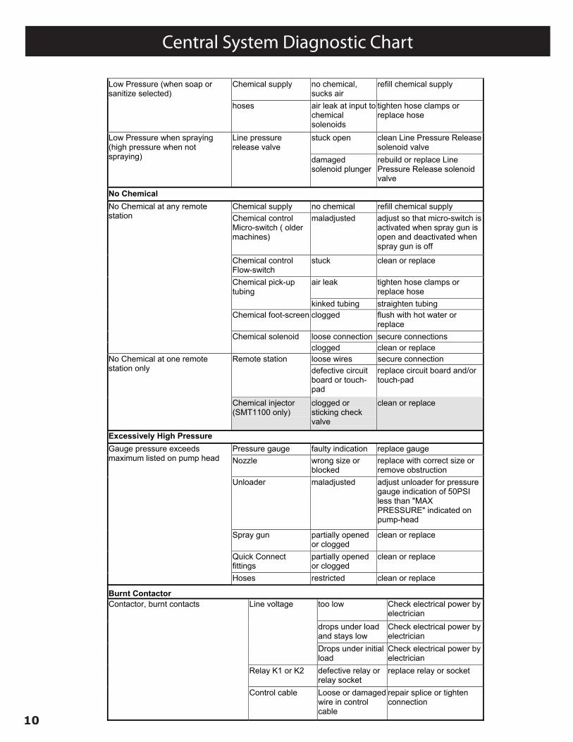
Chemical supply no chemical, sucks air
refill chemical supply Low Pressure (when soap or sanitize selected)
hoses air leak at input to chemical solenoids
tighten hose clamps or replace hose
stuck open clean Line Pressure Release solenoid valve
Low Pressure when spraying (high pressure when not spraying)
Line pressure release valve
damaged solenoid plunger
rebuild or replace Line Pressure Release solenoid valve
No Chemical
Chemical supply no chemical refill chemical supply Chemical control Micro-switch ( older machines)
maladjusted adjust so that micro-switch is activated when spray gun is open and deactivated when spray gun is off
Chemical control Flow-switch
stuck clean or replace
air leak tighten hose clamps or replace hose
Chemical pick-up tubing
kinked tubing straighten tubing Chemical foot-screen clogged flush with hot water or
replace loose connection secure connections
No Chemical at any remote station
Chemical solenoid clogged clean or replace loose wires secure connection Remote station defective circuit board or touch-pad
replace circuit board and/or touch-pad
No Chemical at one remote station only
Chemical injector (SMT1100 only)
clogged or sticking check valve
clean or replace
Excessively High Pressure
Pressure gauge faulty indication replace gauge Nozzle wrong size or
blocked replace with correct size or remove obstruction
Unloader maladjusted adjust unloader for pressure gauge indication of 50PSI less than "MAX PRESSURE" indicated on pump-head
Spray gun partially opened or clogged
clean or replace
Quick Connect fittings
partially opened or clogged
clean or replace
Gauge pressure exceeds maximum listed on pump head
Hoses restricted clean or replace
16
Burnt Contactor
too low Check electrical power by electrician
drops under load and stays low
Check electrical power by electrician
Line voltage
Drops under initial load
Check electrical power by electrician
Relay K1 or K2 defective relay or relay socket
replace relay or socket
Contactor, burnt contacts
Control cable Loose or damaged wire in control cable
repair splice or tighten connection
11
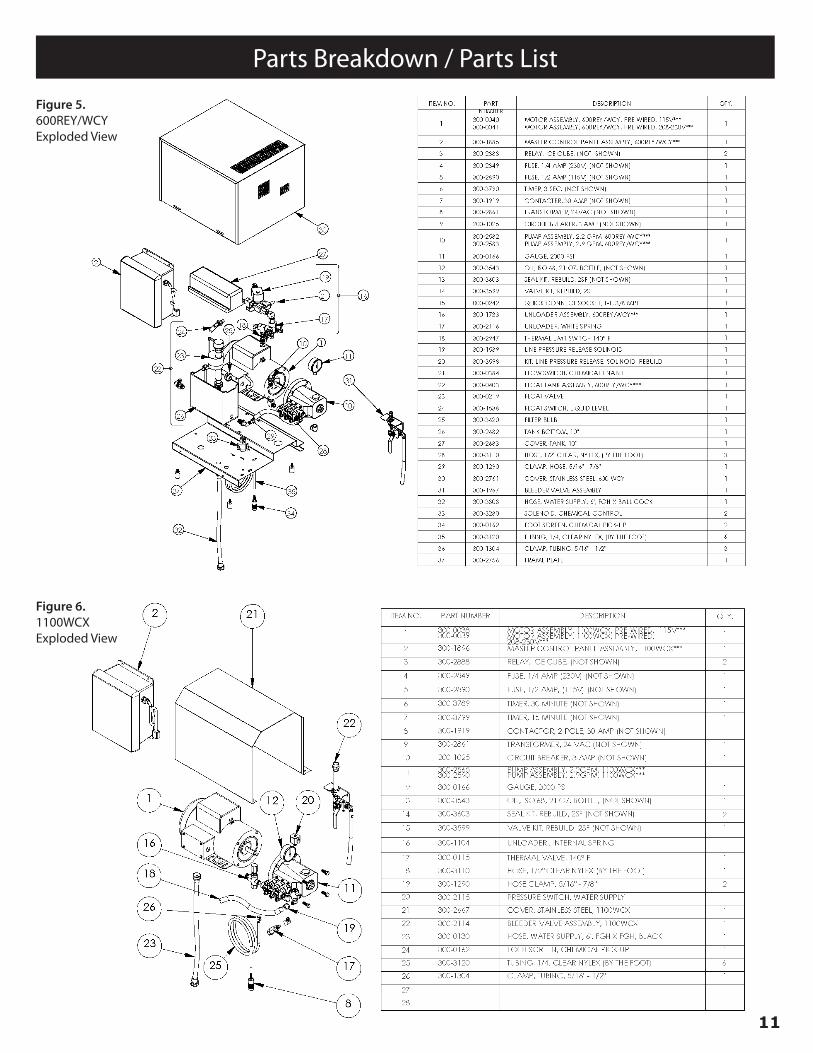
Parts Breakdown / Parts List
Figure 5.600REY/WCYExploded View
Figure 6.1100WCXExploded View
12
Parts Breakdown / Parts List
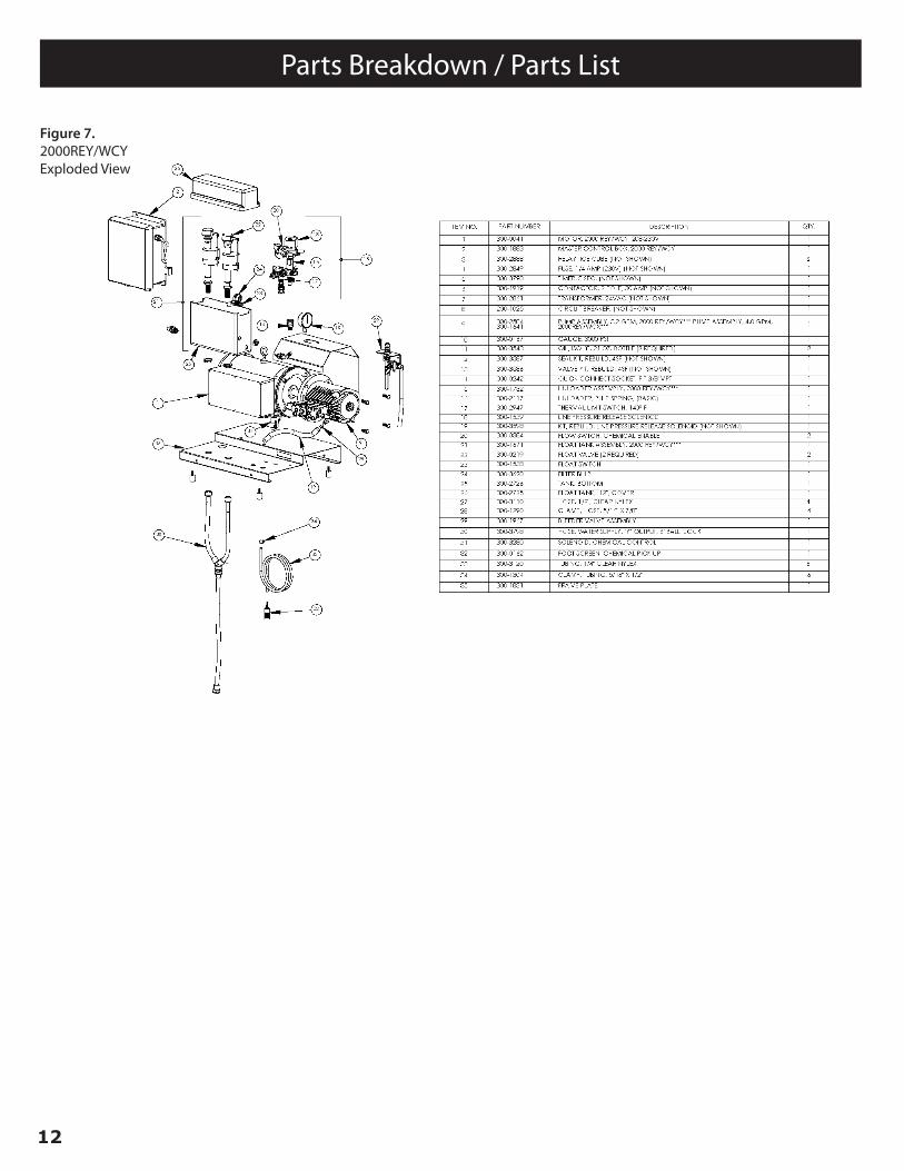
Figure 7.2000REY/WCYExploded View
13
Parts Breakdown / Parts List
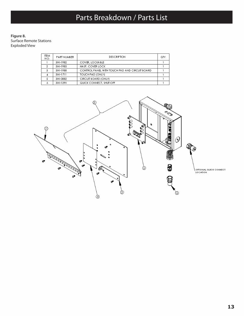
Figure 8.Surface Remote StationsExploded View
14
Parts Breakdown / Parts List
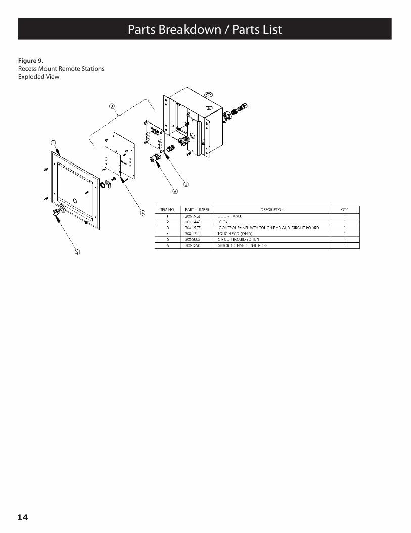
Figure 9.Recess Mount Remote StationsExploded View
15
Parts Breakdown / Parts List
21
ITEMNO.
PART NUMBER DESCRIPTION QTY.
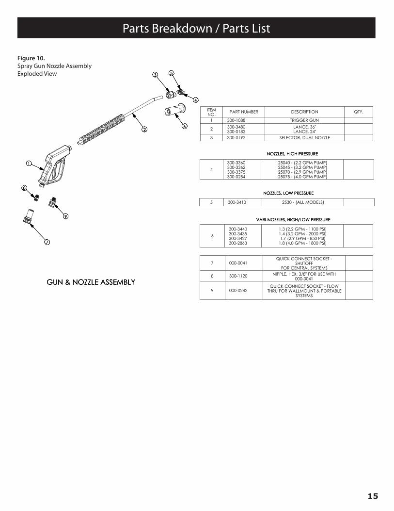
1 300-1088 TRIGGER GUN
2 300-3480300-0182
LANCE, 36"LANCE, 24"
3 300-0192 SELECTOR, DUAL NOZZLE
5 300-3410 2530 - (ALL MODELS)
6
300-3440300-3435300-3427300-2863
1.3 (2.2 GPM - 1100 PSI)1.4 (3.2 GPM - 2000 PSI)1.7 (2.9 GPM - 850 PSI)
1.8 (4.0 GPM - 1800 PSI)
7 000-0041QUICK CONNECT SOCKET -
SHUTOFFFOR CENTRAL SYSTEMS
8 300-1120 NIPPLE, HEX, 3/8" FOR USE WITH000-0041
9 000-0242QUICK CONNECT SOCKET - FLOW
THRU FOR WALLMOUNT & PORTABLESYSTEMS
4
300-3360300-3362300-3375300-0254
25040 - (2.2 GPM PUMP)25045 - (3.2 GPM PUMP)25070 - (2.9 GPM PUMP)25075 - (4.0 GPM PUMP)
NOZZLES, LOW PRESSURE
VARI-NOZZLES, HIGH/LOW PRESSURE
NOZZLES, HIGH PRESSURE
GUN & NOZZLE ASSEMBLY
7
9
8
1
26
3 5
4
300-3300-00
NOZZLES, LOW PRESSURE
VARI-NOZZLES, HIGH/LOW PRESSURE
NOZZLES, HIGH PRESSURE
GUN & NOZZLE ASSEMBLY
7
9
8
1
26
3 5
4
300-3300-00
NOZZLES, LOW PRESSURE
VARI-NOZZLES, HIGH/LOW PRESSURE
NOZZLES, HIGH PRESSURE
GUN & NOZZLE ASSEMBLY
7
9
8
1
26
3 5
4
300-3300-00
Figure 10. Exploded View, SMT Spray Gun Assembly
Figure 10.Spray Gun Nozzle AssemblyExploded View
SPRAY MASTER TECHNOLOGIES®A product line of Assembled Products Corporation
115 E. Linden Street, Rogers, Arkansas 72756
479-636-5776 • 800-548-3373
spraymastertech.com
SMT-CSYSEXPRESS-SM-130808-EN Price and specifications are subject to change without notice . Printed in the USA.