Embed Size (px)
Citation preview
Exposing Photo Manipulation with
Geometric InconsistenciesJames F. O’Brien
U.C. Berkeley
CollaboratorsHany Farid Eric Kee Valentina Conotter Stephen Bailey
1 image-forensics-PG14.key - October 9, 2014

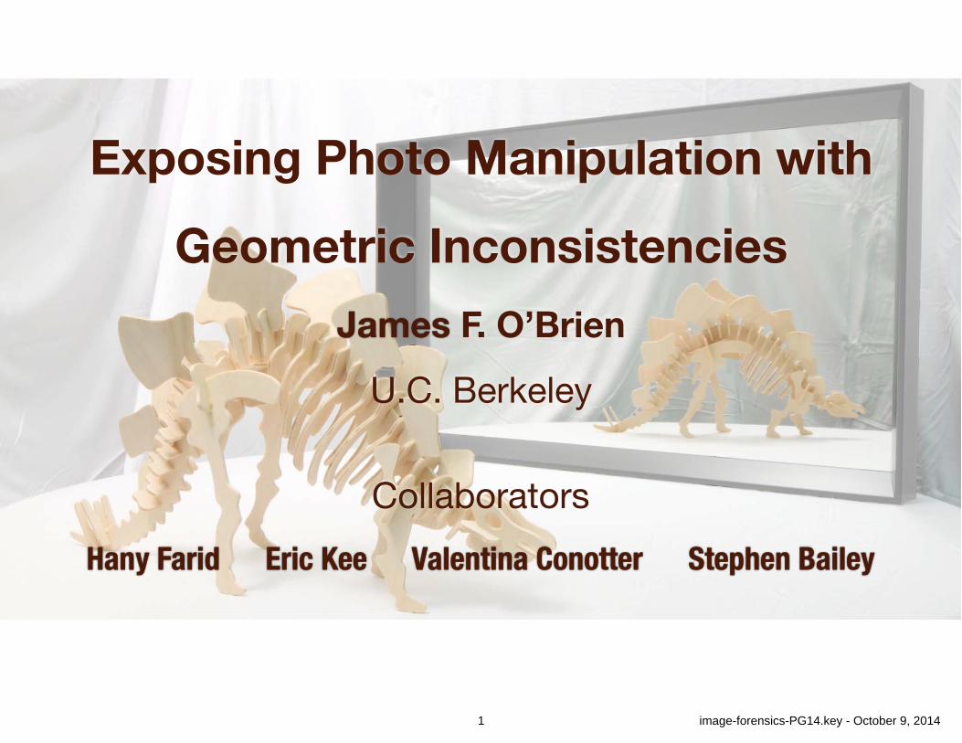
Communication by Images
2-1 image-forensics-PG14.key - October 9, 2014
Communication by Images
2-2 image-forensics-PG14.key - October 9, 2014
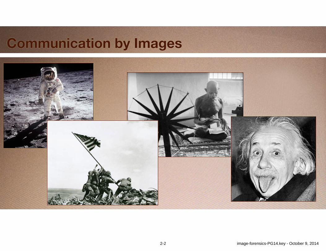
Image Manipulation
Iranian missile test, 2008
3-1 image-forensics-PG14.key - October 9, 2014
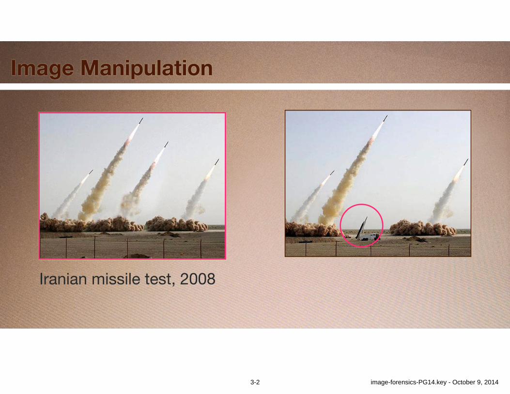
Image Manipulation
Iranian missile test, 2008
3-2 image-forensics-PG14.key - October 9, 2014
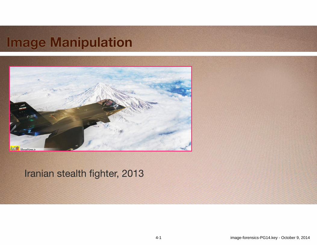
Image Manipulation
Iranian stealth fighter, 2013
4-1 image-forensics-PG14.key - October 9, 2014
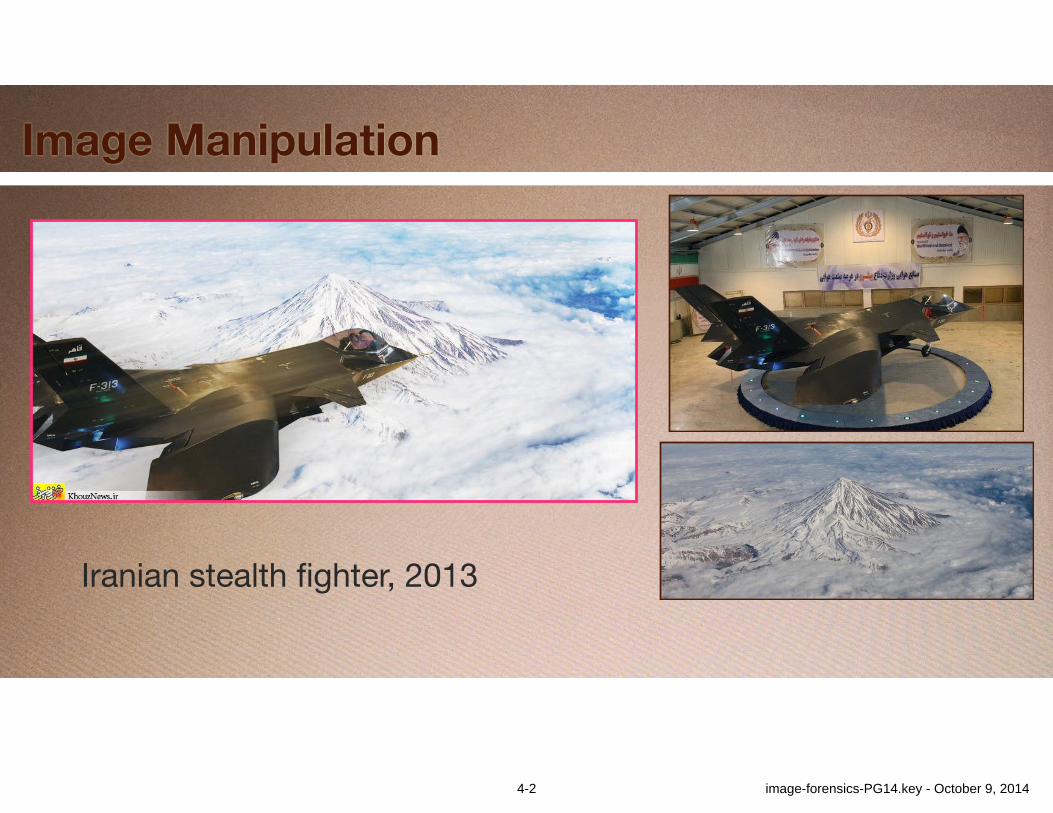
Image Manipulation
Iranian stealth fighter, 2013
4-2 image-forensics-PG14.key - October 9, 2014
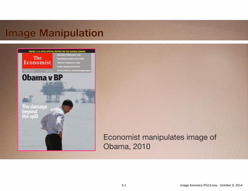
Image Manipulation
Economist manipulates image of Obama, 2010
5-1 image-forensics-PG14.key - October 9, 2014
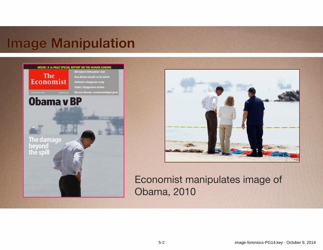
Image Manipulation
Economist manipulates image of Obama, 2010
5-2 image-forensics-PG14.key - October 9, 2014
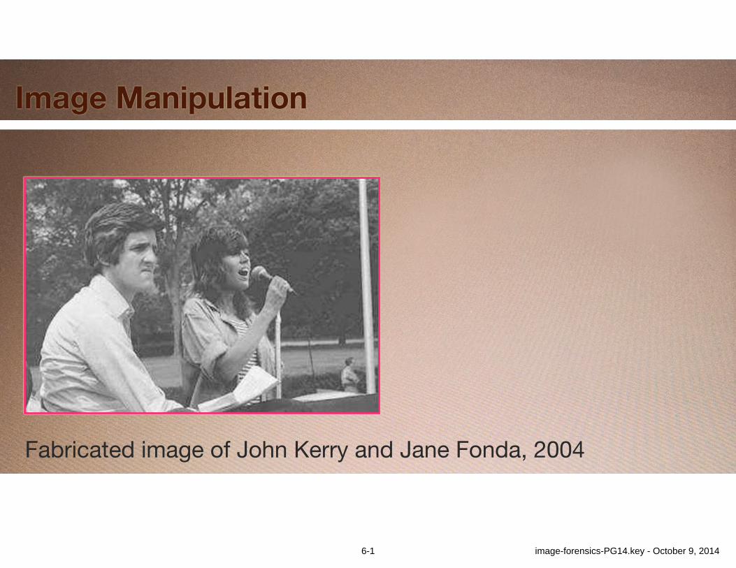
Image Manipulation
Fabricated image of John Kerry and Jane Fonda, 2004
6-1 image-forensics-PG14.key - October 9, 2014
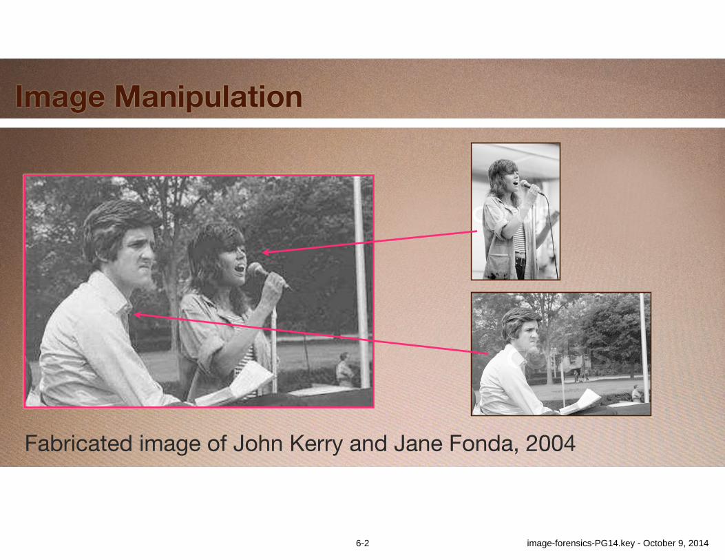
Image Manipulation
Fabricated image of John Kerry and Jane Fonda, 2004
6-2 image-forensics-PG14.key - October 9, 2014
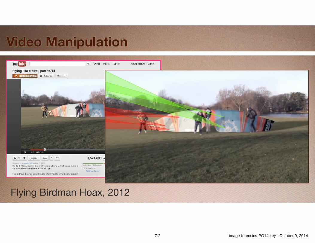
Video Manipulation
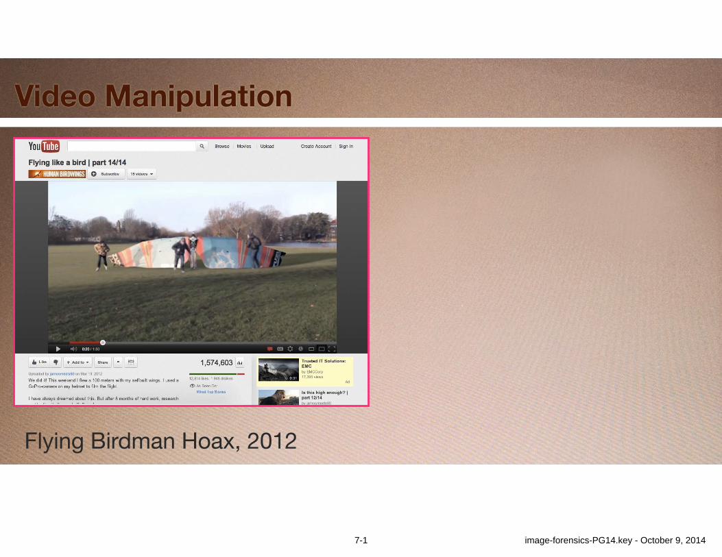
Flying Birdman Hoax, 2012
7-1 image-forensics-PG14.key - October 9, 2014
Video Manipulation
Flying Birdman Hoax, 2012
7-2 image-forensics-PG14.key - October 9, 2014
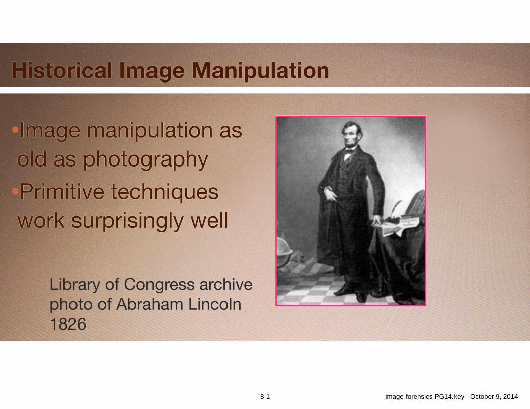
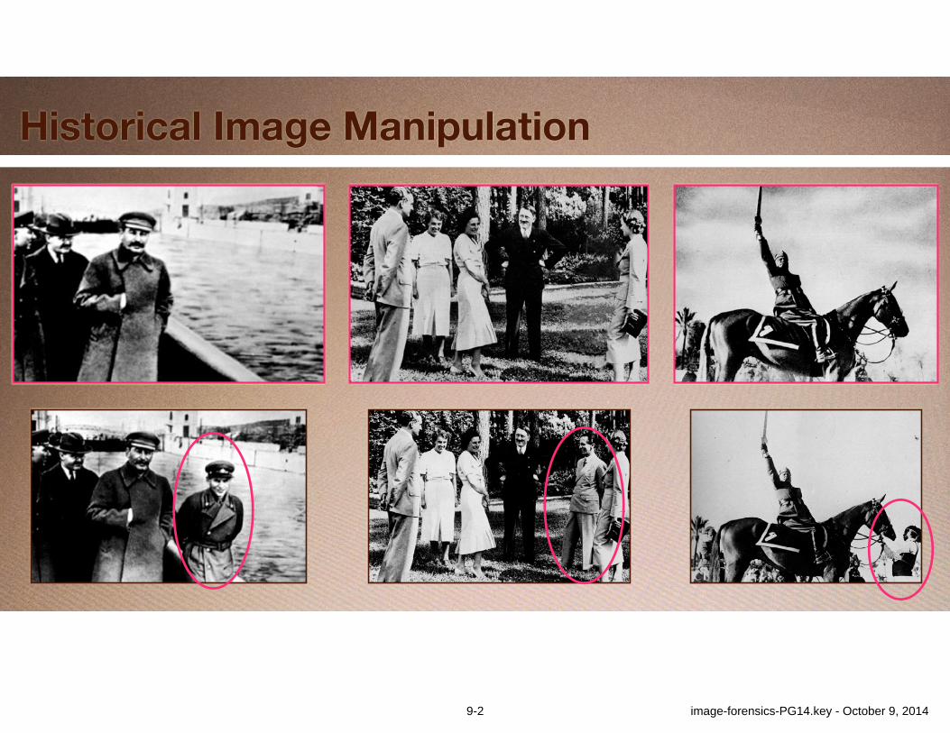
Historical Image Manipulation
•Image manipulation as old as photography•Primitive techniques work surprisingly well
Library of Congress archivephoto of Abraham Lincoln1826
8-1 image-forensics-PG14.key - October 9, 2014
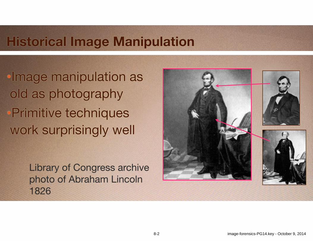
Historical Image Manipulation
•Image manipulation as old as photography•Primitive techniques work surprisingly well
Library of Congress archivephoto of Abraham Lincoln1826
8-2 image-forensics-PG14.key - October 9, 2014
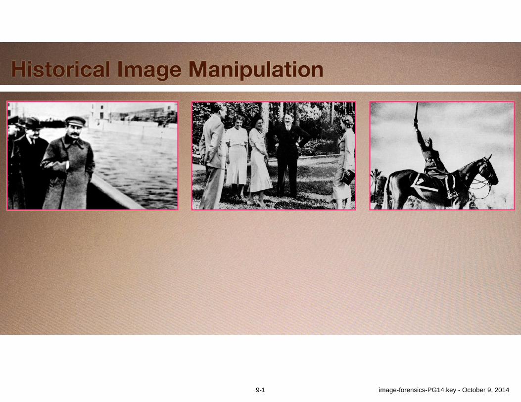
Historical Image Manipulation
9-1 image-forensics-PG14.key - October 9, 2014
Historical Image Manipulation
9-2 image-forensics-PG14.key - October 9, 2014
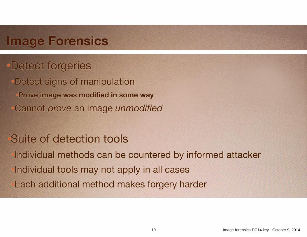
Image Forensics
•Detect forgeries•Detect signs of manipulation•Prove image was modified in some way
•Cannot prove an image unmodified!
•Suite of detection tools•Individual methods can be countered by informed attacker•Individual tools may not apply in all cases •Each additional method makes forgery harder
10 image-forensics-PG14.key - October 9, 2014

Advantage: Forgers
•People: •Good at understanding scene content•Poor at noticing many types of inconsistencies•Simple manipulation methods work well•New manipulation methods being developed
11 image-forensics-PG14.key - October 9, 2014
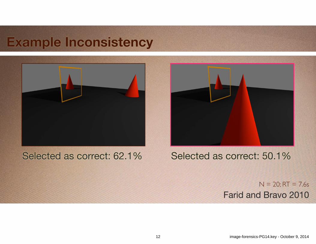
Example Inconsistency
N = 20; RT = 7.6sFarid and Bravo 2010
Selected as correct: 62.1% Selected as correct: 50.1%
12 image-forensics-PG14.key - October 9, 2014
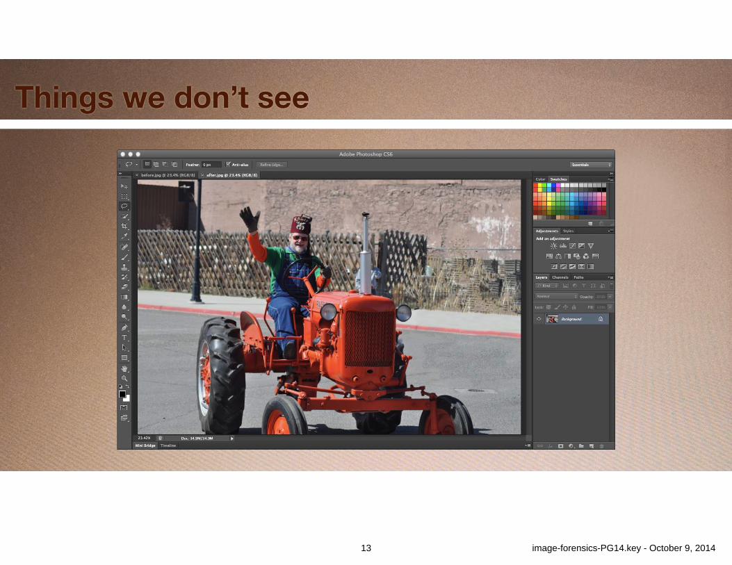
Things we don’t see
13 image-forensics-PG14.key - October 9, 2014
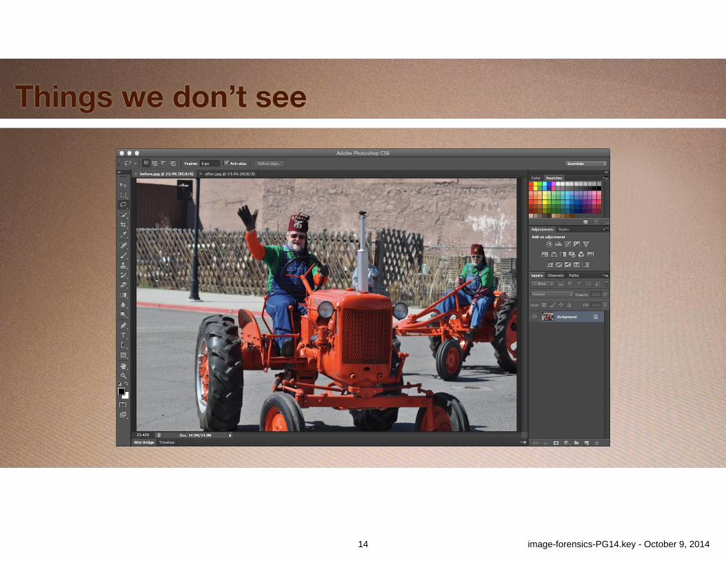
Things we don’t see
14 image-forensics-PG14.key - October 9, 2014
Advantage: Forgers
•People: •Good at understanding scene content•Poor at noticing many types of inconsistencies•Simple manipulation methods work well•New manipulation methods being developed
15 image-forensics-PG14.key - October 9, 2014
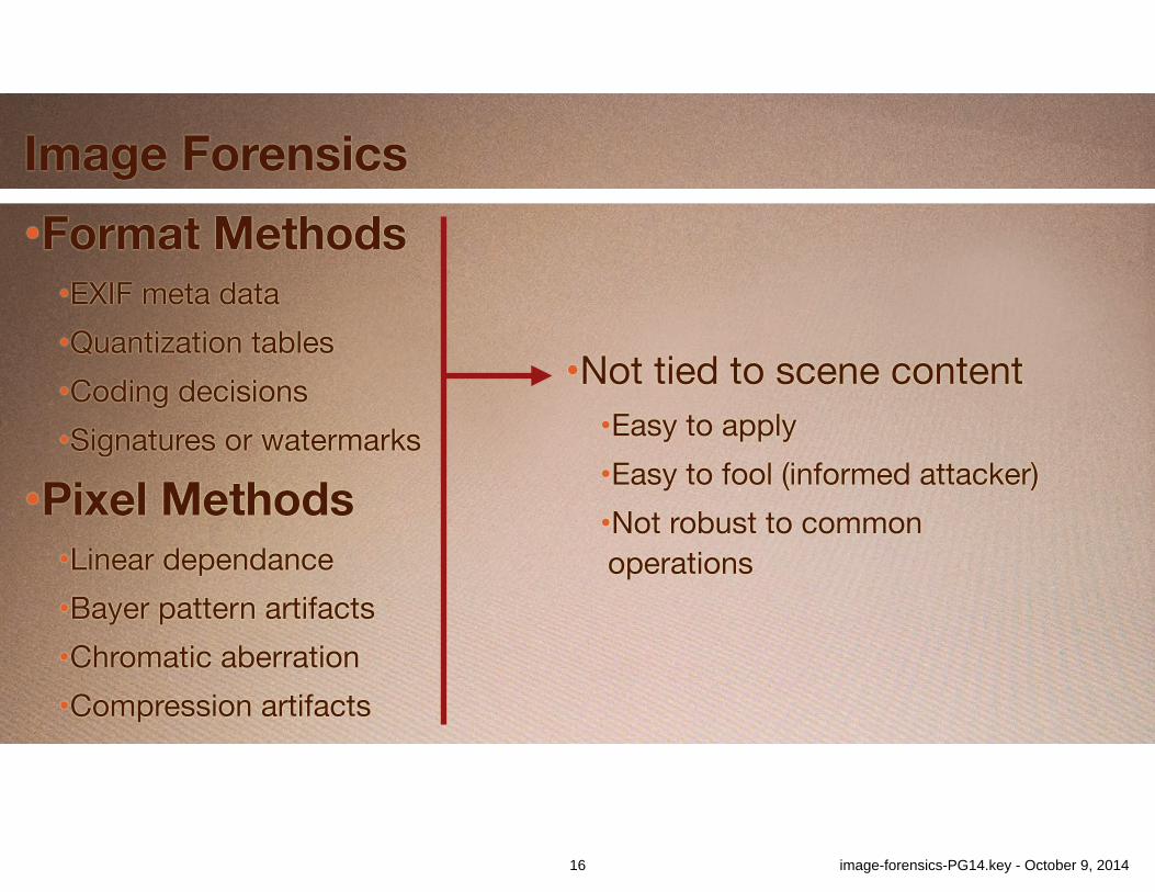
Image Forensics•Format Methods
•EXIF meta data•Quantization tables•Coding decisions•Signatures or watermarks
•Pixel Methods •Linear dependance•Bayer pattern artifacts •Chromatic aberration•Compression artifacts
•Not tied to scene content•Easy to apply•Easy to fool (informed attacker)•Not robust to common operations
16 image-forensics-PG14.key - October 9, 2014
Image Forensics
•Geometric methods •Content inconsistencies•Require human annotation•Computer analysis
•Examples:•Shadows•Lighting•Reflections
17 image-forensics-PG14.key - October 9, 2014
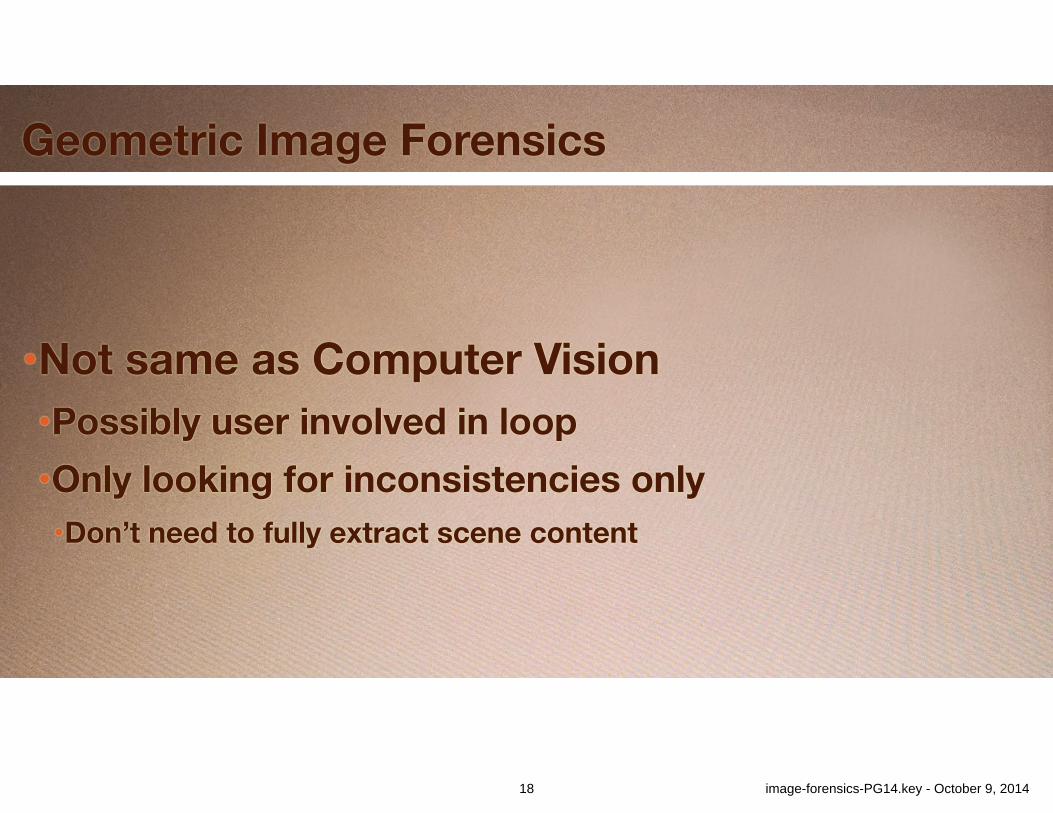
Geometric Image Forensics
•Not same as Computer Vision •Possibly user involved in loop •Only looking for inconsistencies only •Don’t need to fully extract scene content
18 image-forensics-PG14.key - October 9, 2014
19 image-forensics-PG14.key - October 9, 2014
20 image-forensics-PG14.key - October 9, 2014
21 image-forensics-PG14.key - October 9, 2014
22 image-forensics-PG14.key - October 9, 2014
23 image-forensics-PG14.key - October 9, 2014
24 image-forensics-PG14.key - October 9, 2014
25 image-forensics-PG14.key - October 9, 2014
26 image-forensics-PG14.key - October 9, 2014
27 image-forensics-PG14.key - October 9, 2014
28 image-forensics-PG14.key - October 9, 2014

29 image-forensics-PG14.key - October 9, 2014
30 image-forensics-PG14.key - October 9, 2014
31 image-forensics-PG14.key - October 9, 2014
32 image-forensics-PG14.key - October 9, 2014
33 image-forensics-PG14.key - October 9, 2014
34 image-forensics-PG14.key - October 9, 2014
35 image-forensics-PG14.key - October 9, 2014
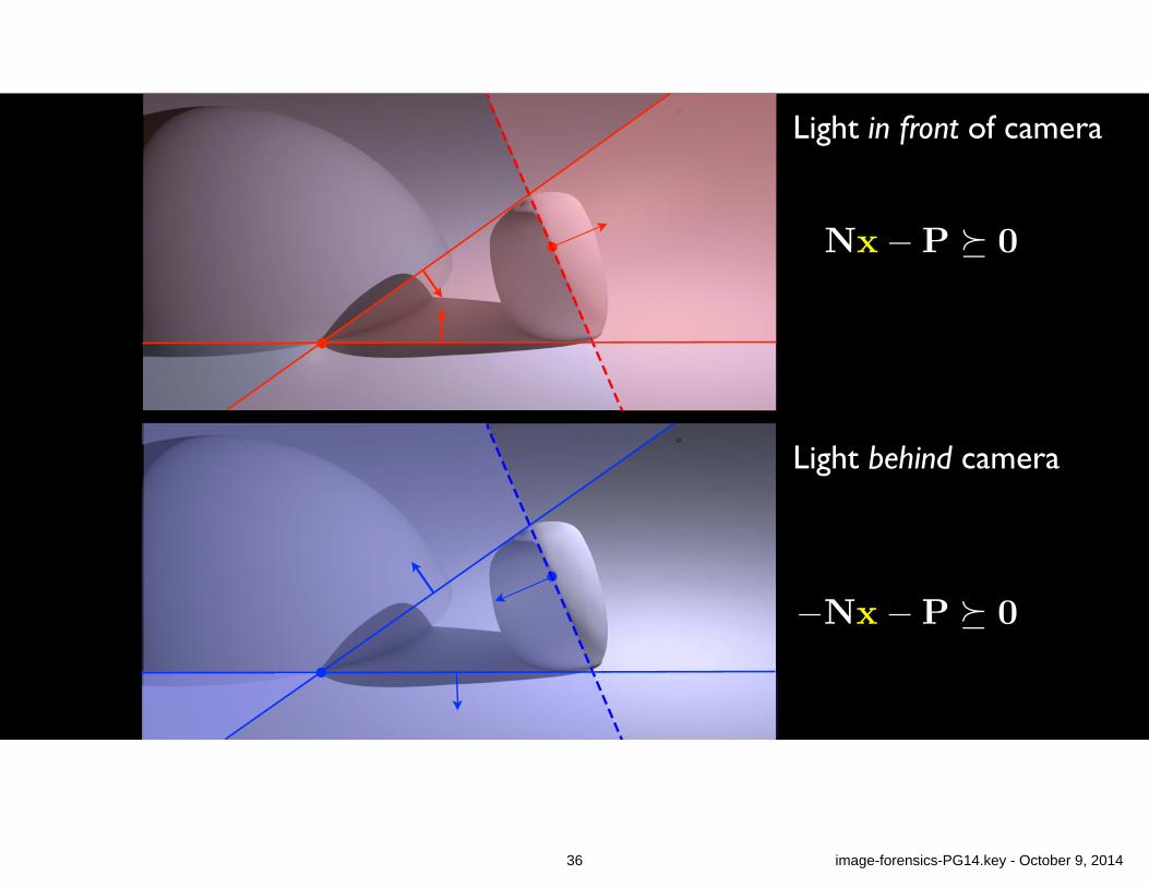
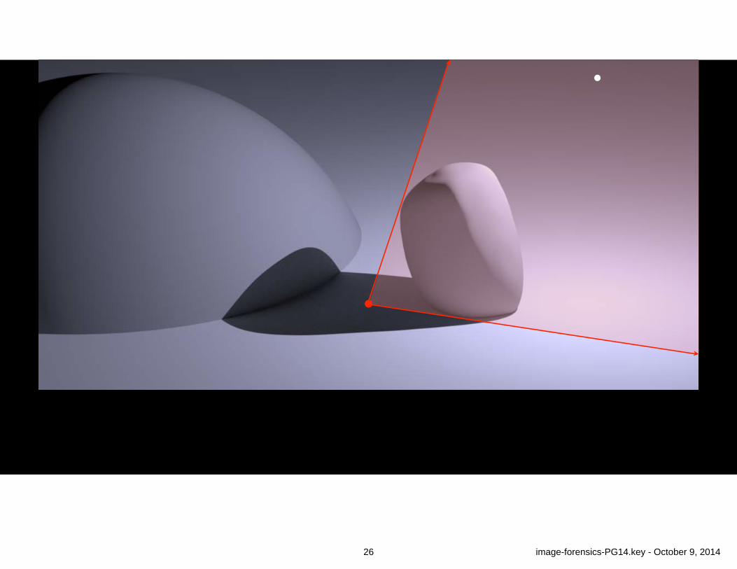
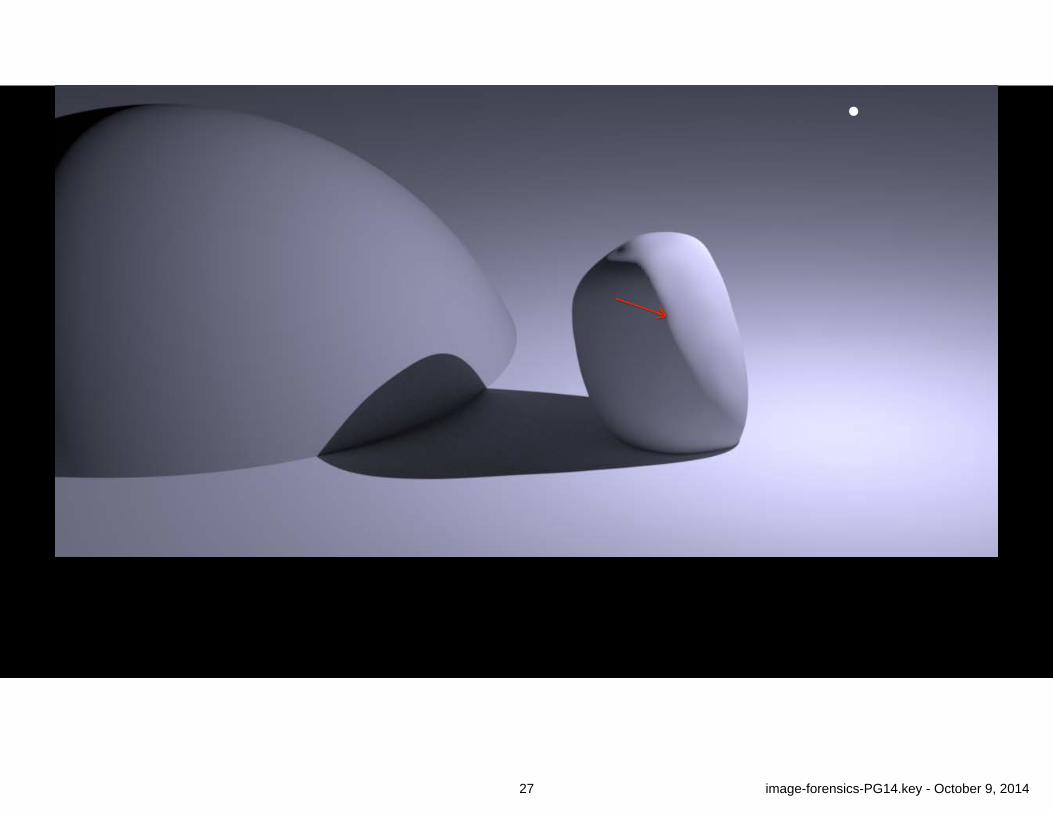
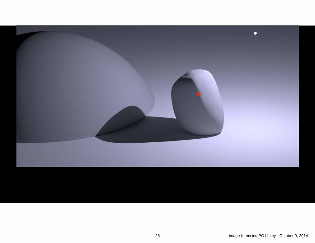
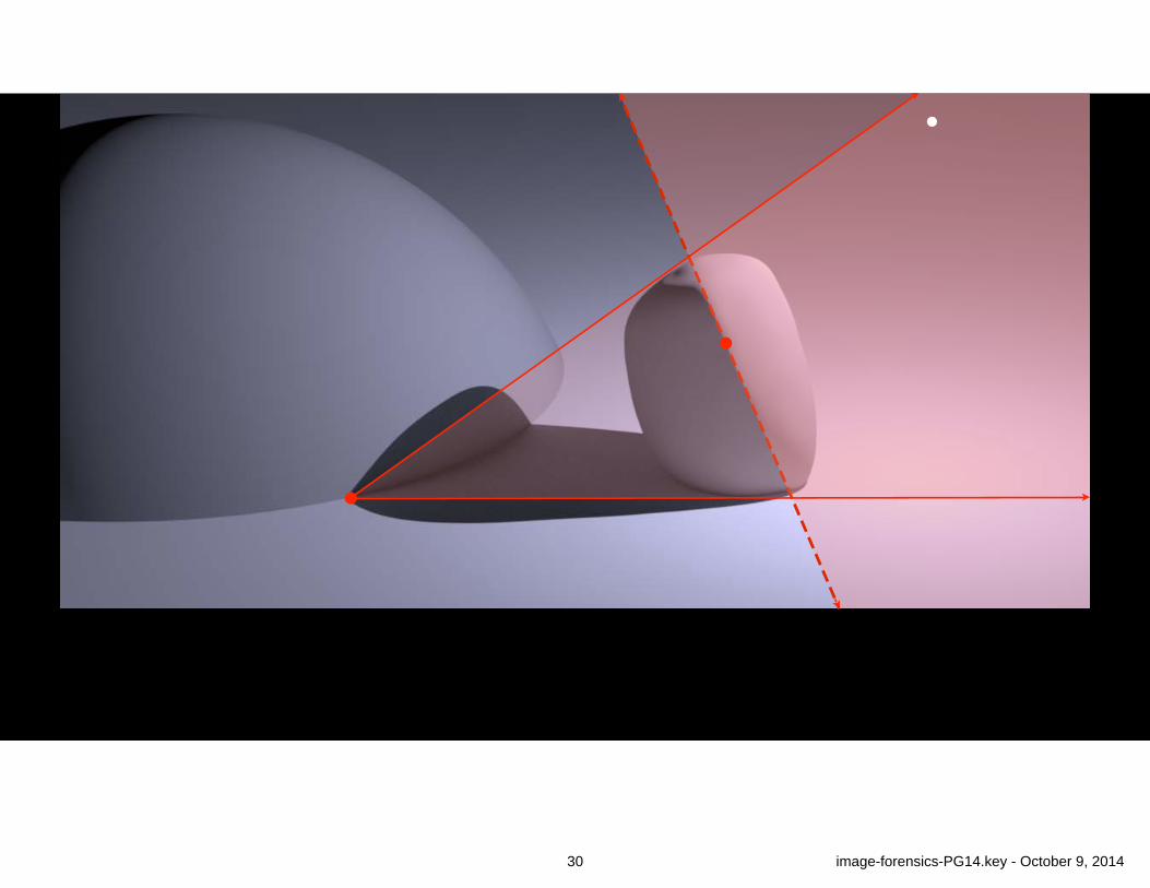
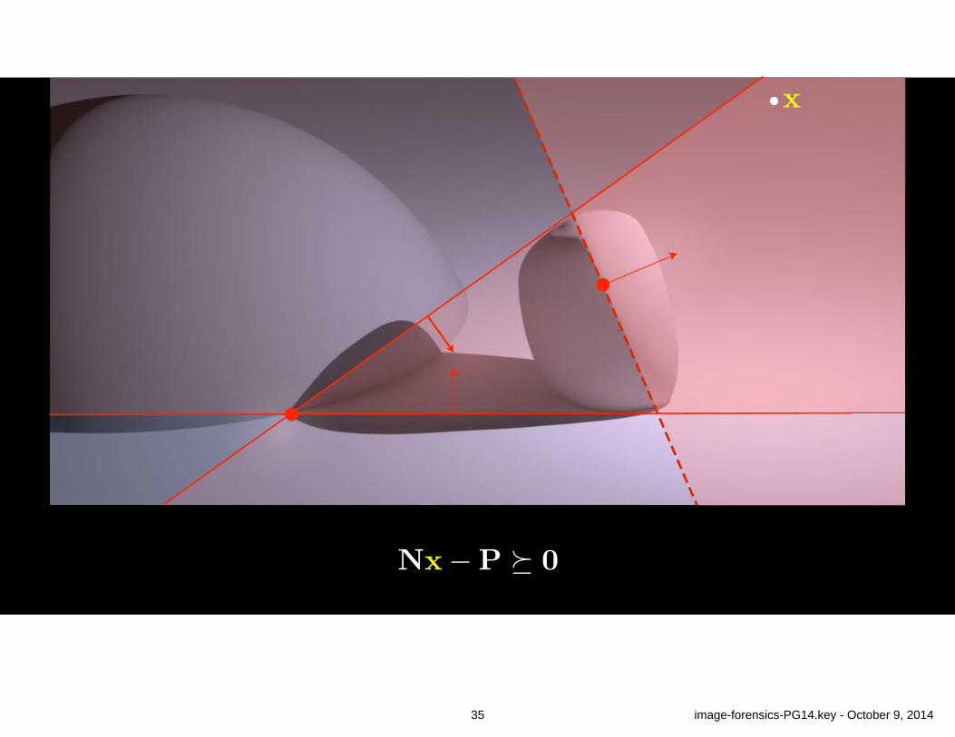
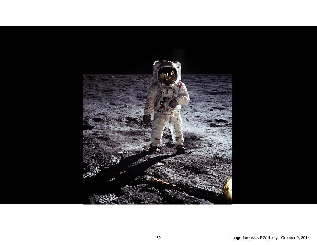
Light in front of camera
Light behind camera
36 image-forensics-PG14.key - October 9, 2014
37 image-forensics-PG14.key - October 9, 2014
38 image-forensics-PG14.key - October 9, 2014
39 image-forensics-PG14.key - October 9, 2014
40 image-forensics-PG14.key - October 9, 2014
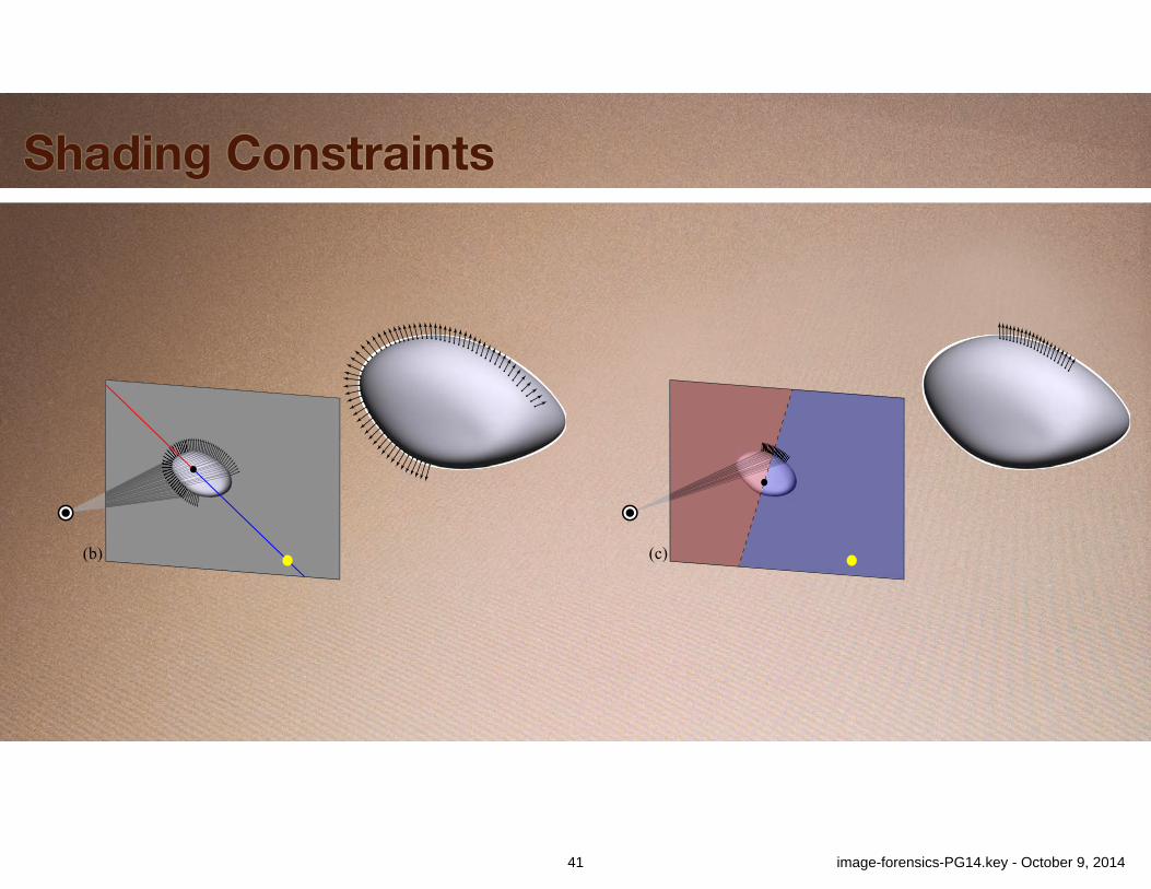
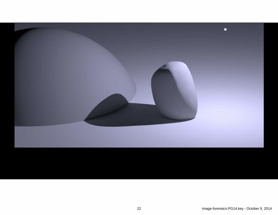
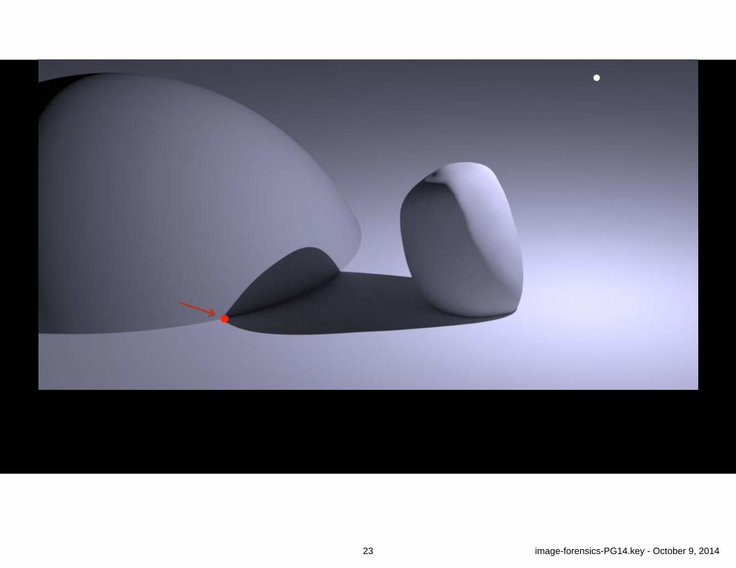
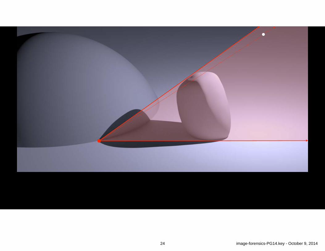
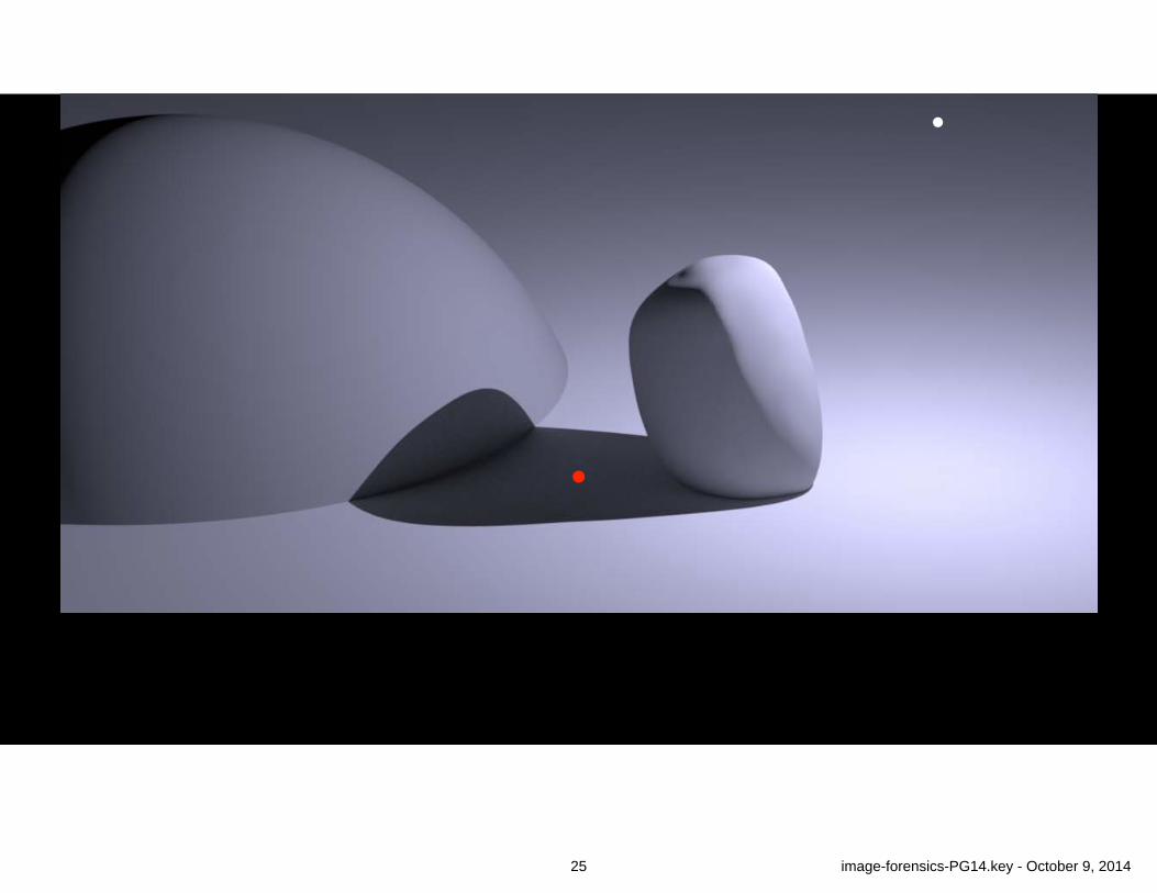
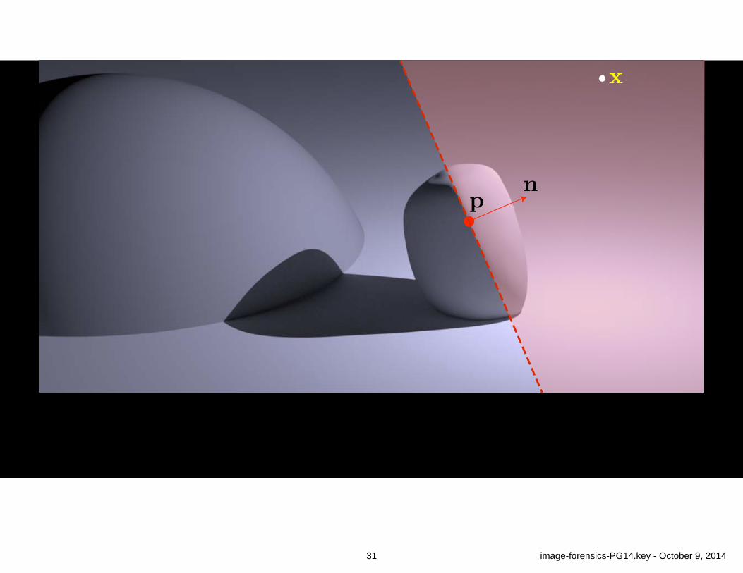
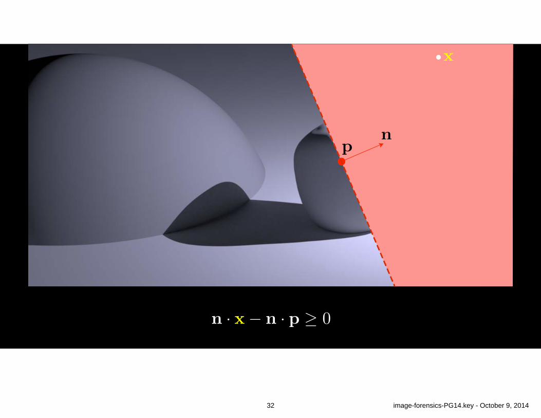
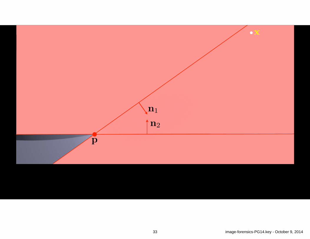
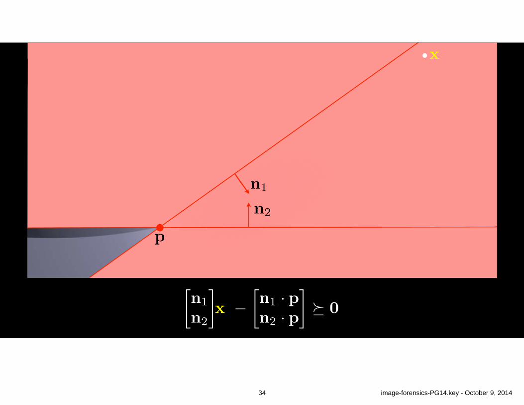
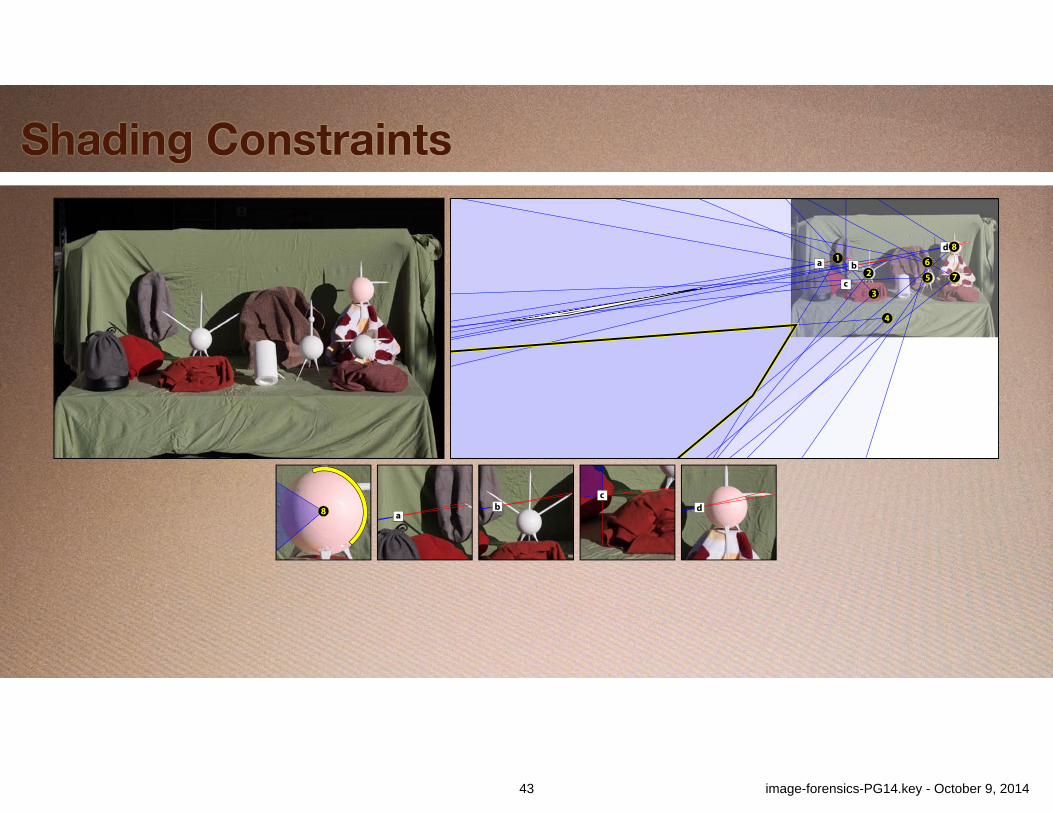
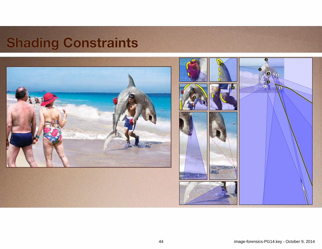
Shading Constraints
(c)(b)
41 image-forensics-PG14.key - October 9, 2014
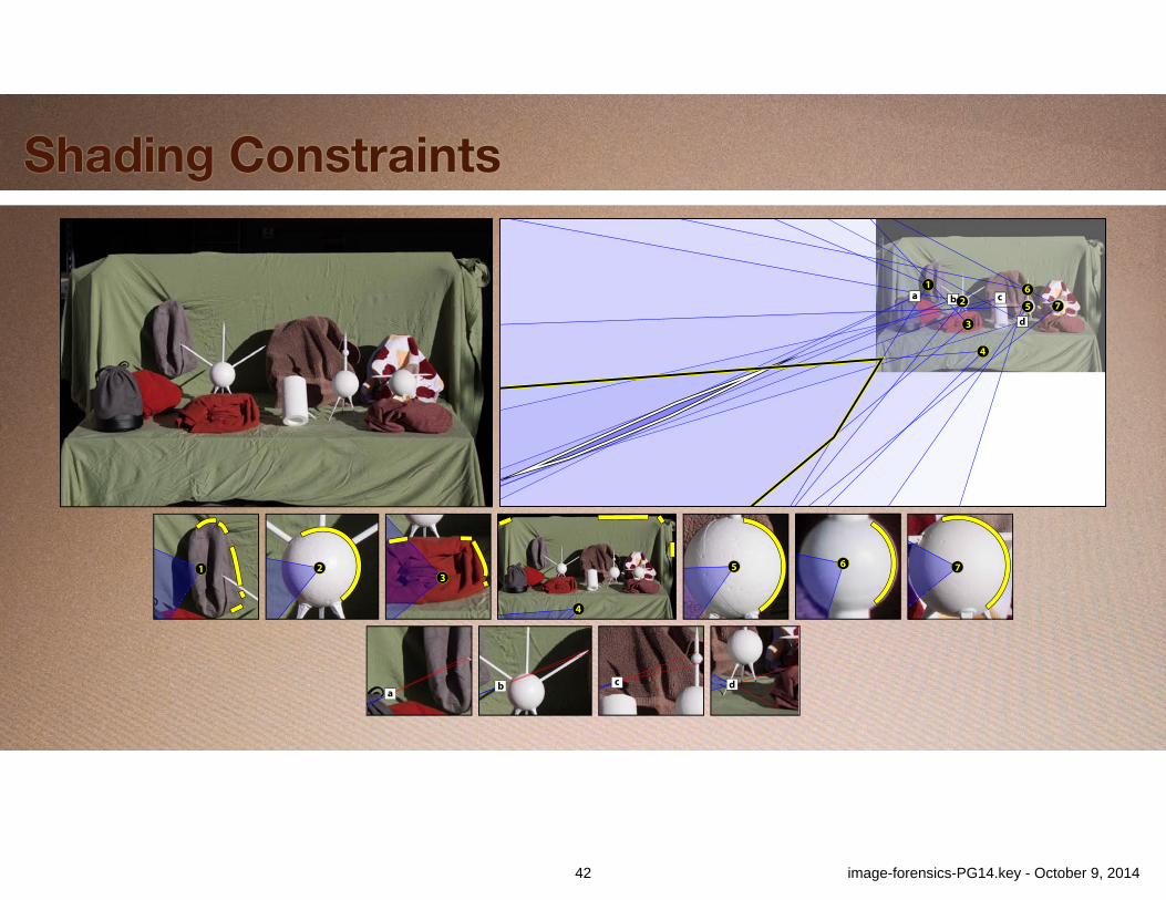
Shading Constraints
8 ab
cd
d
b
c
a 12
3
4
5
67
8
ab c d
765
4
321
a b c
d
12
3
4
5
67
42 image-forensics-PG14.key - October 9, 2014
Shading Constraints
8 ab
cd
d
b
c
a 12
3
4
5
67
8
ab c d
765
4
321
a b c
d
12
3
4
5
67
43 image-forensics-PG14.key - October 9, 2014
Shading Constraints
c
b
a
4
3
21
b
a
c
3
2
1
4
44 image-forensics-PG14.key - October 9, 2014
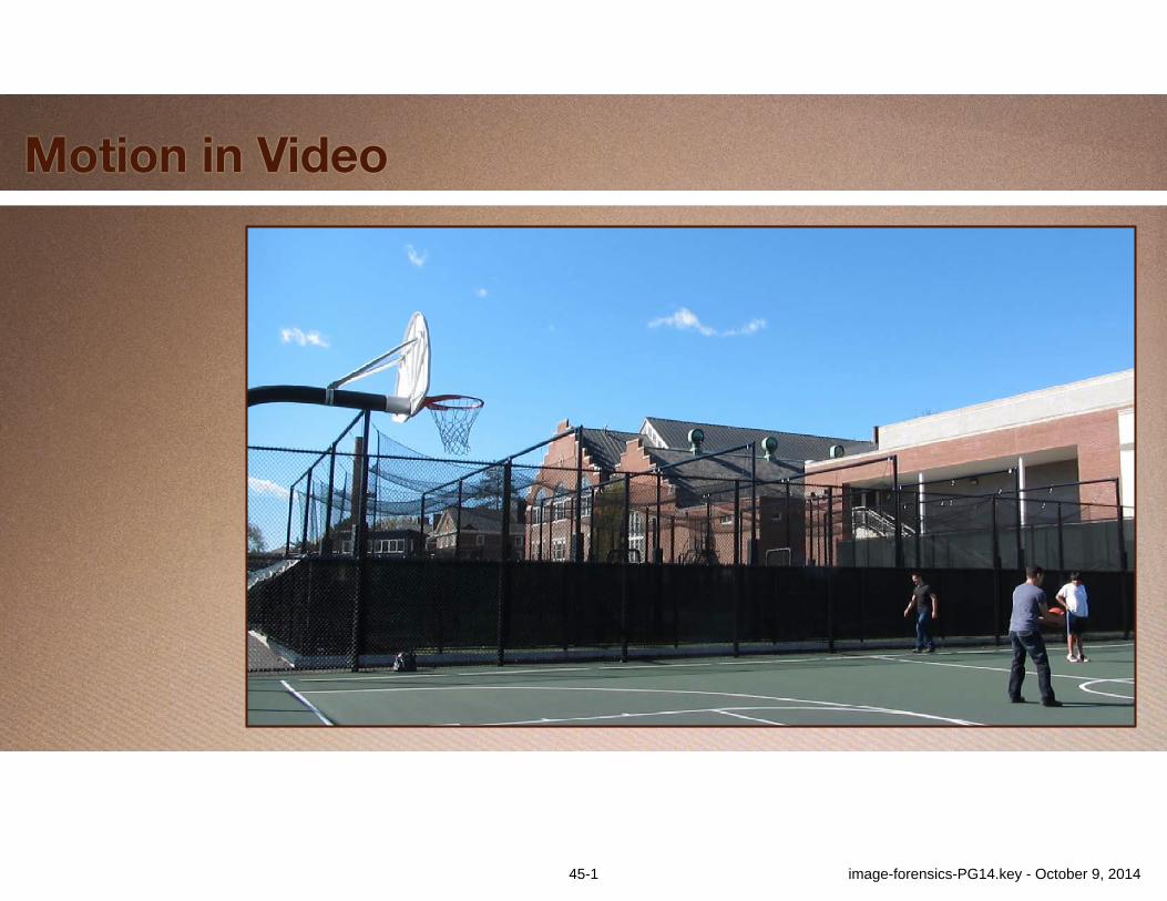
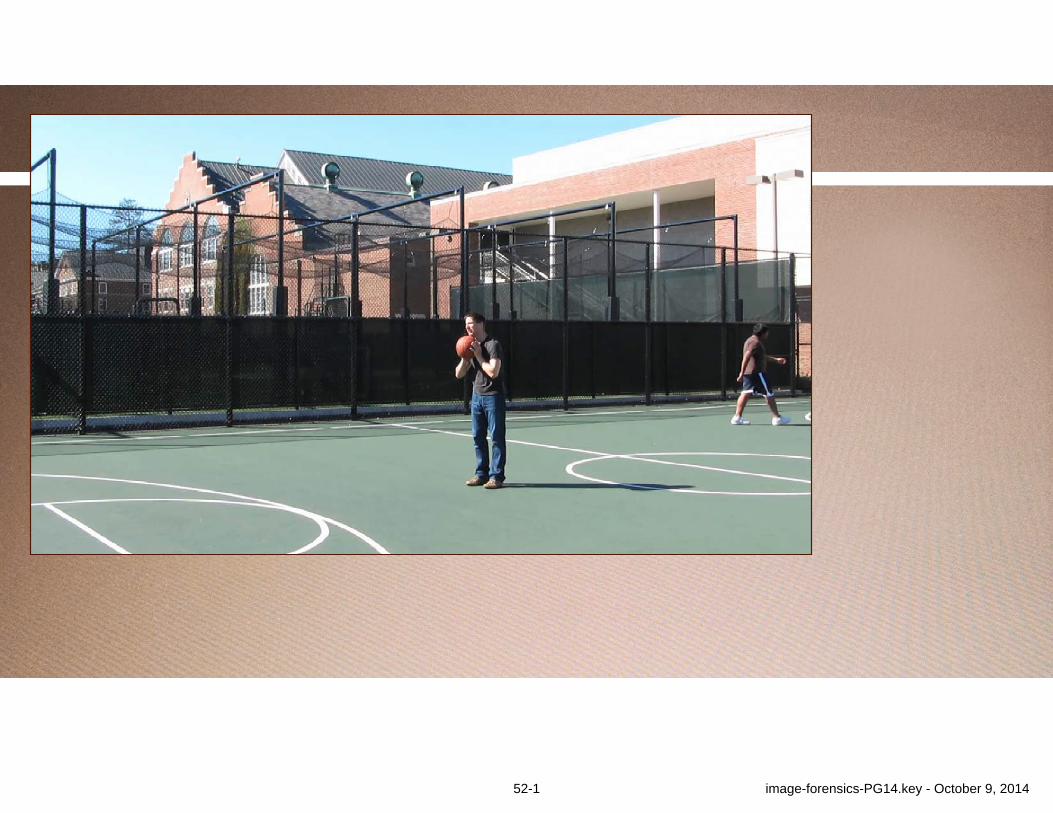
Motion in Video
45-1 image-forensics-PG14.key - October 9, 2014

Motion in Video
45-2 image-forensics-PG14.key - October 9, 2014
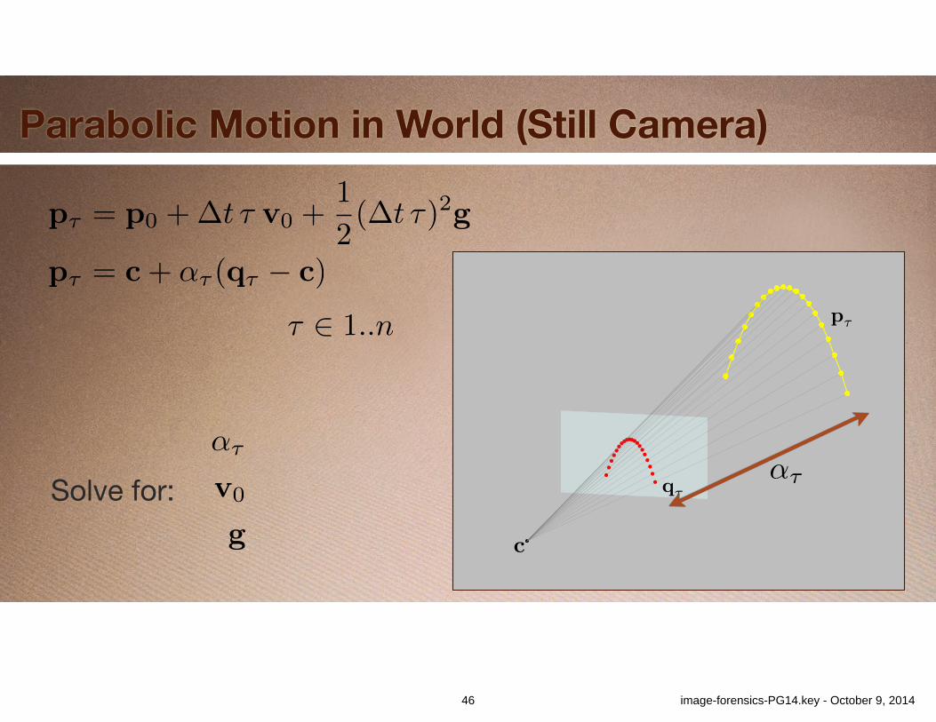
Parabolic Motion in World (Still Camera)
c
q⌧
p⌧
p⌧ = c+ ↵⌧ (q⌧ � c)
↵⌧
⌧ 2 1..n
p⌧ = p0 +�t ⌧ v0 +1
2(�t ⌧)2g
Solve for:↵⌧
v0
g
46 image-forensics-PG14.key - October 9, 2014
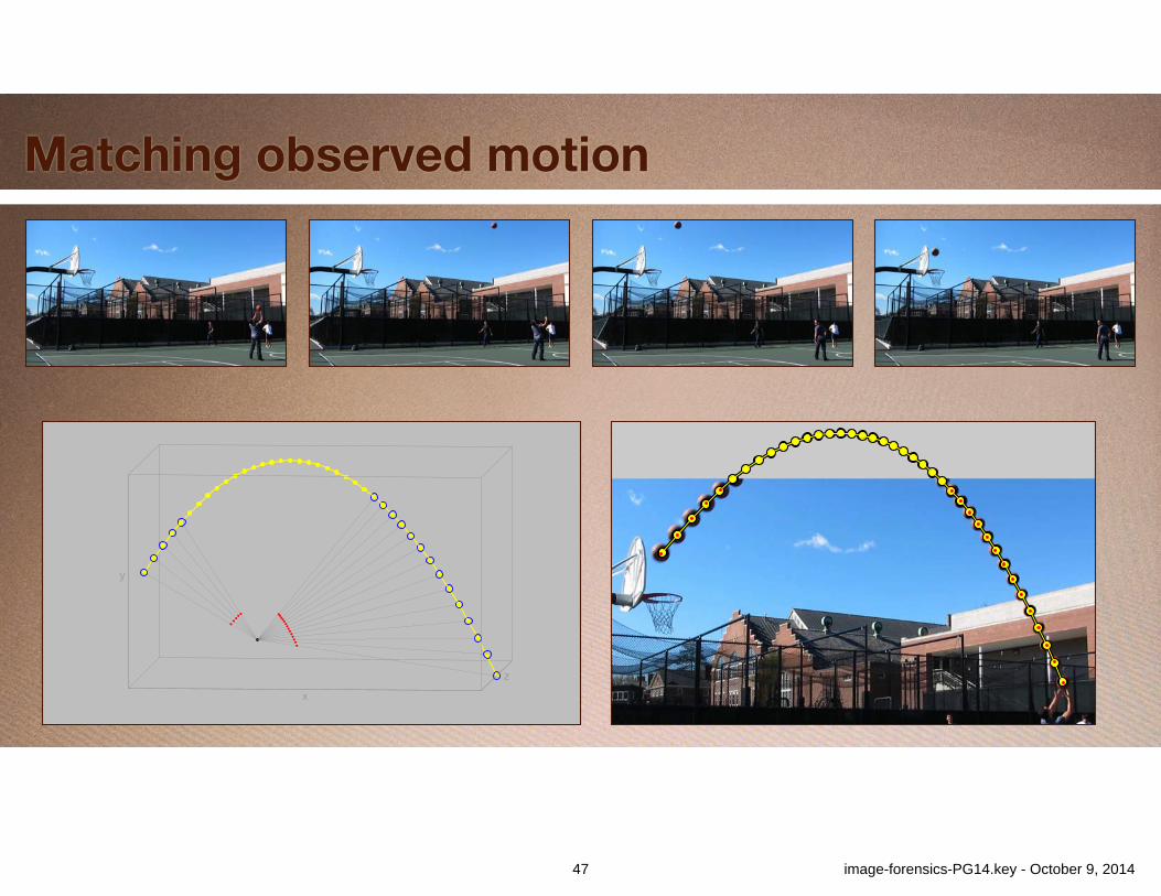
Matching observed motion
z
x
y
47 image-forensics-PG14.key - October 9, 2014
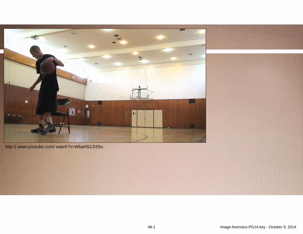
http:// www.youtube.com/ watch?v=WbaH52JI3So
48-1 image-forensics-PG14.key - October 9, 2014

http:// www.youtube.com/ watch?v=WbaH52JI3So
48-2 image-forensics-PG14.key - October 9, 2014

49-1 image-forensics-PG14.key - October 9, 2014
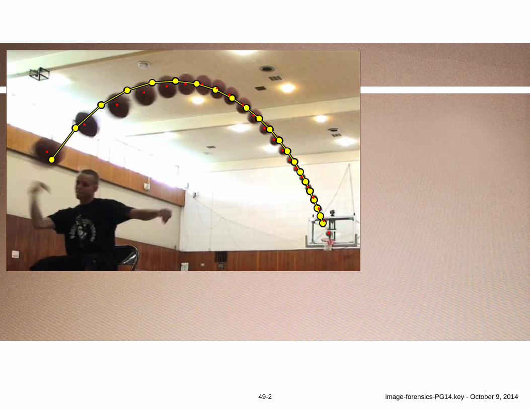
49-2 image-forensics-PG14.key - October 9, 2014
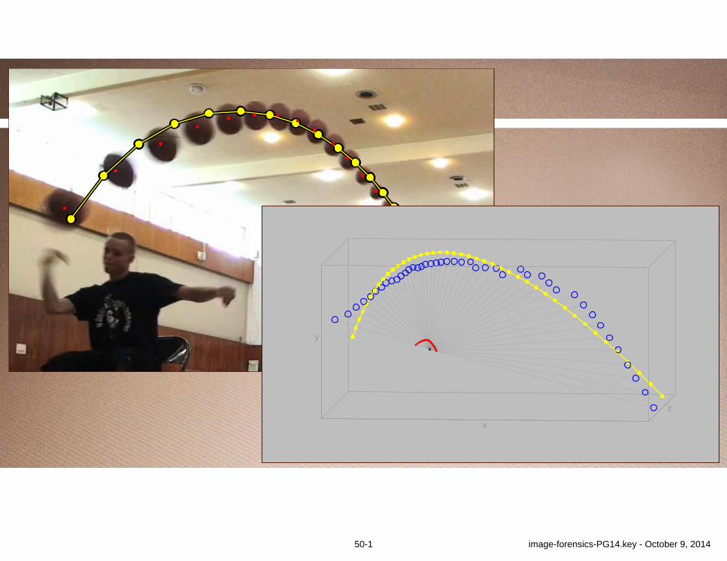
zx
y
50-1 image-forensics-PG14.key - October 9, 2014

zx
y
50-2 image-forensics-PG14.key - October 9, 2014
c⌧
q⌧
p⌧
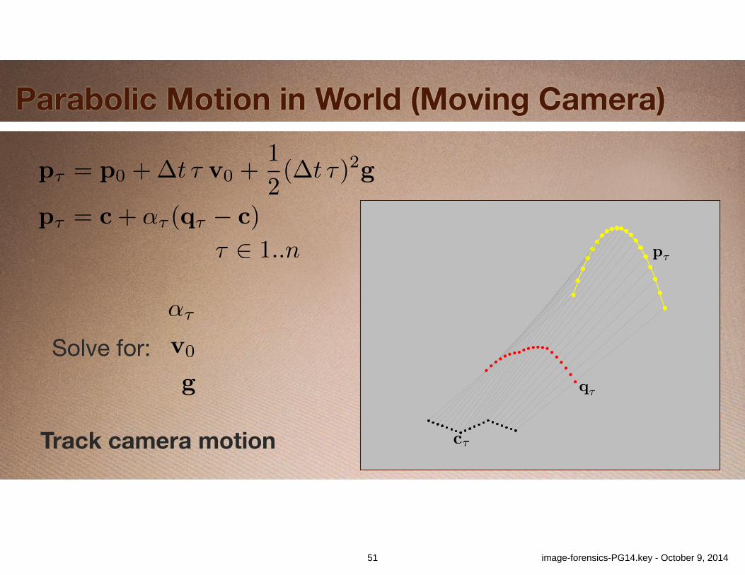
Parabolic Motion in World (Moving Camera)
p⌧ = c+ ↵⌧ (q⌧ � c)
⌧ 2 1..n
p⌧ = p0 +�t ⌧ v0 +1
2(�t ⌧)2g
Solve for:↵⌧
v0
g
Track camera motion
51 image-forensics-PG14.key - October 9, 2014
52-1 image-forensics-PG14.key - October 9, 2014

52-2 image-forensics-PG14.key - October 9, 2014
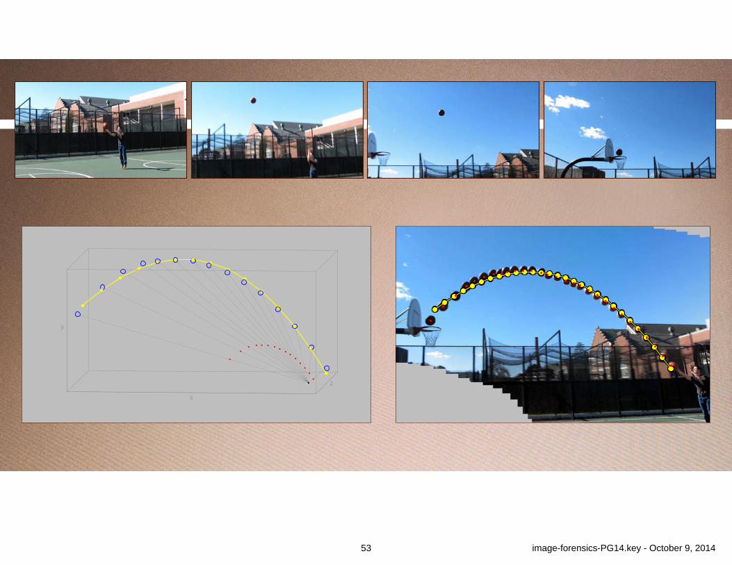
z
x
y
53 image-forensics-PG14.key - October 9, 2014
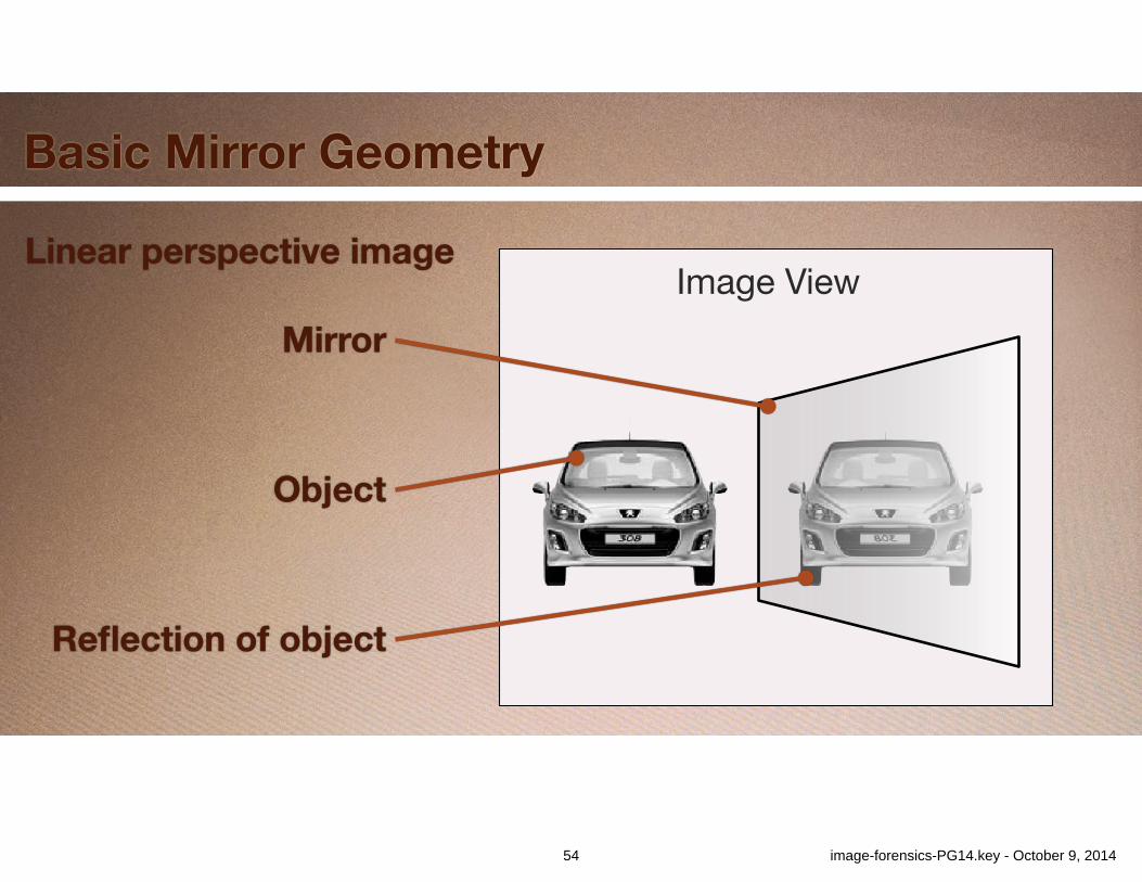
Basic Mirror Geometry
Object
Mirror
Reflection of object
Image ViewLinear perspective image
54 image-forensics-PG14.key - October 9, 2014
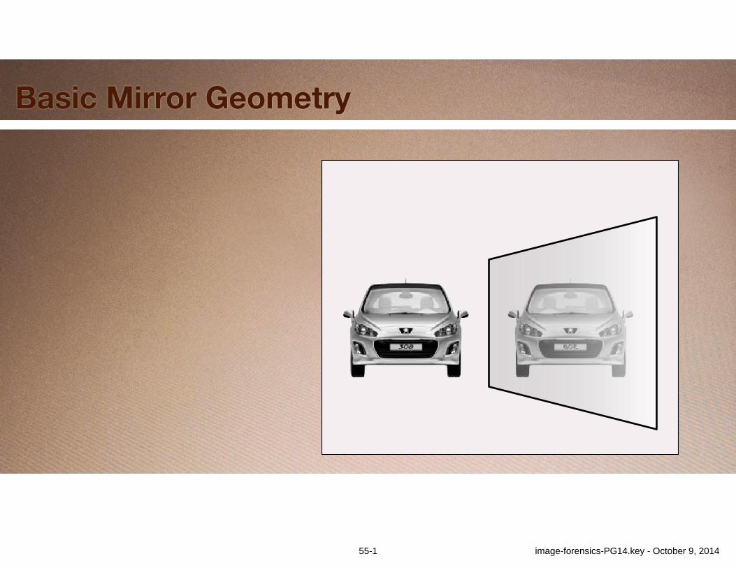
Basic Mirror Geometry
55-1 image-forensics-PG14.key - October 9, 2014
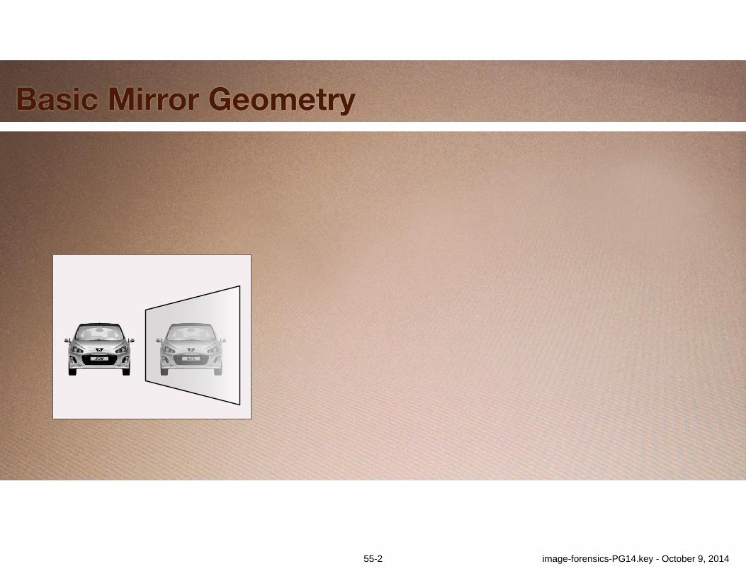
Basic Mirror Geometry
55-2 image-forensics-PG14.key - October 9, 2014

Basic Mirror Geometry
n
COPMirror
Object Point Reflected Point
Mirror-Parallel View
56 image-forensics-PG14.key - October 9, 2014
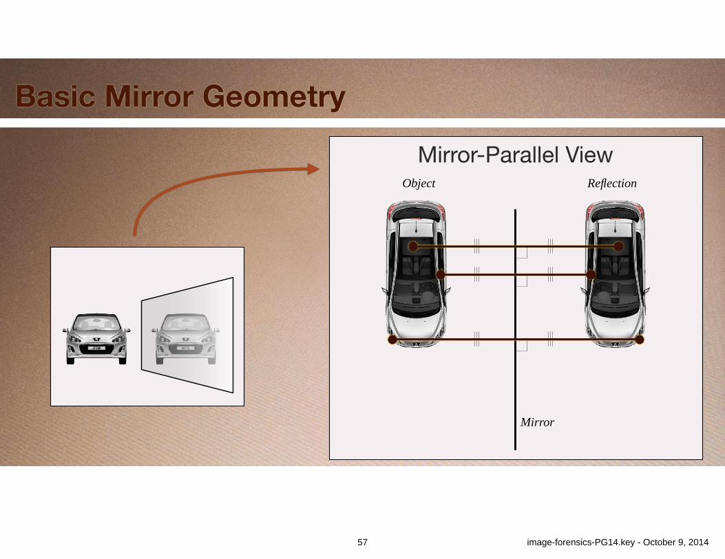
Basic Mirror Geometry
Mirror-Parallel View
Mirror
Object Reflection
57 image-forensics-PG14.key - October 9, 2014
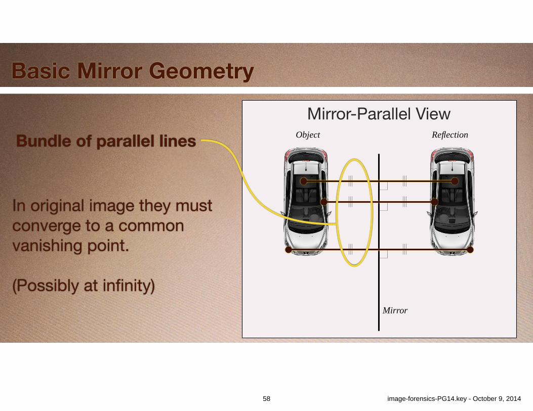
Basic Mirror Geometry
Mirror-Parallel View
Mirror
Object ReflectionBundle of parallel lines
In original image they must converge to a common vanishing point.!
(Possibly at infinity)
58 image-forensics-PG14.key - October 9, 2014

Reflection Vanishing Point
Real Photograph
59 image-forensics-PG14.key - October 9, 2014
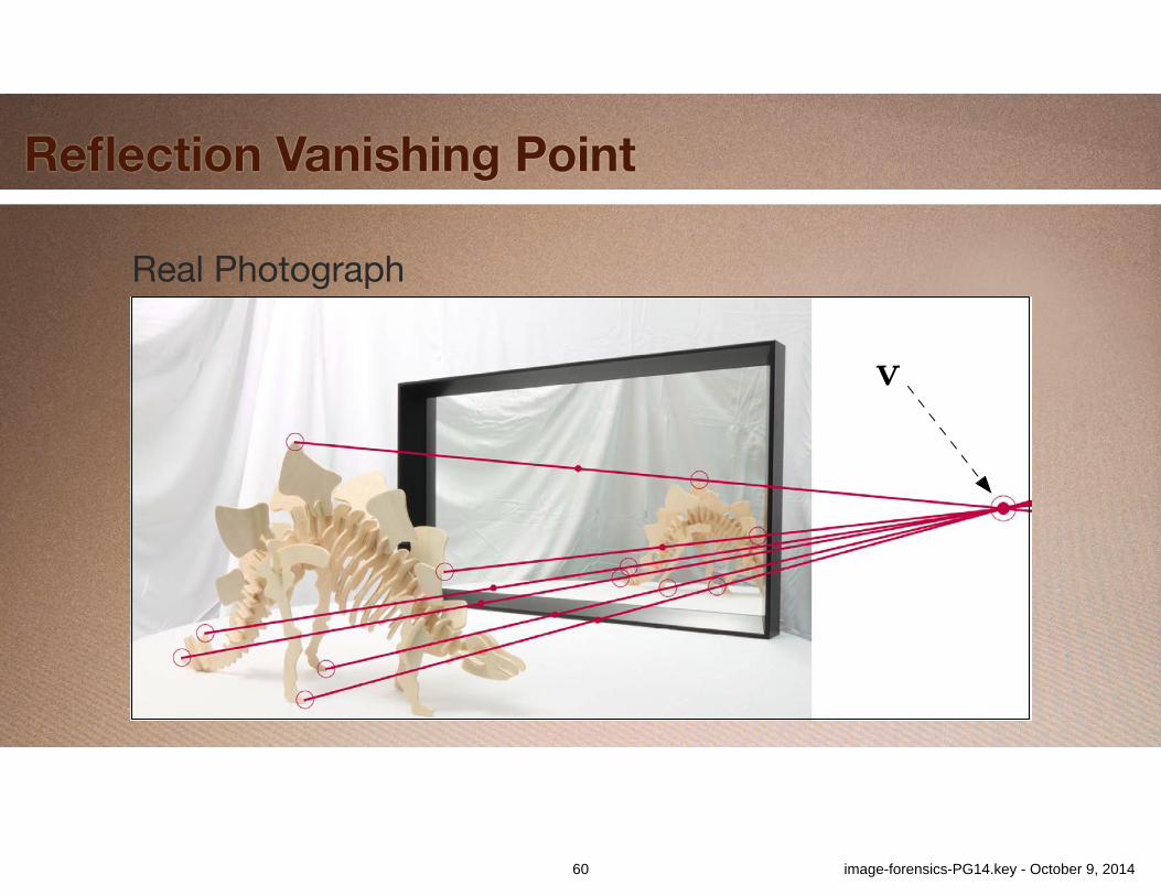
Reflection Vanishing Point
Real Photograph
v
60 image-forensics-PG14.key - October 9, 2014
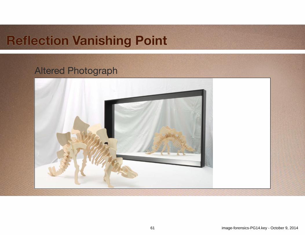
Reflection Vanishing Point
Altered Photograph
61 image-forensics-PG14.key - October 9, 2014
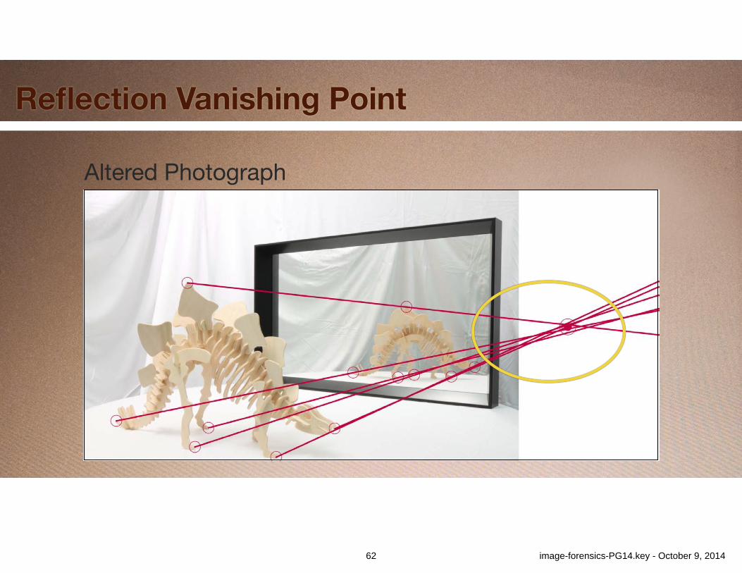
Reflection Vanishing Point
Altered Photograph
62 image-forensics-PG14.key - October 9, 2014
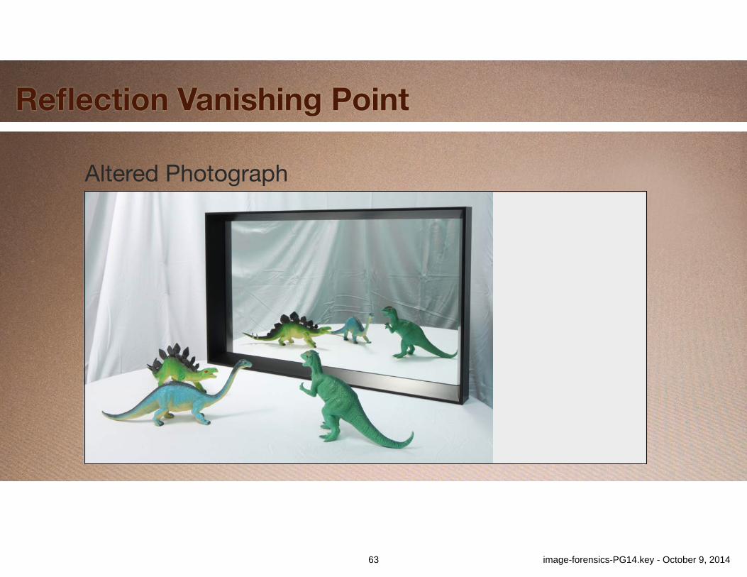
Reflection Vanishing Point
Altered Photograph
63 image-forensics-PG14.key - October 9, 2014
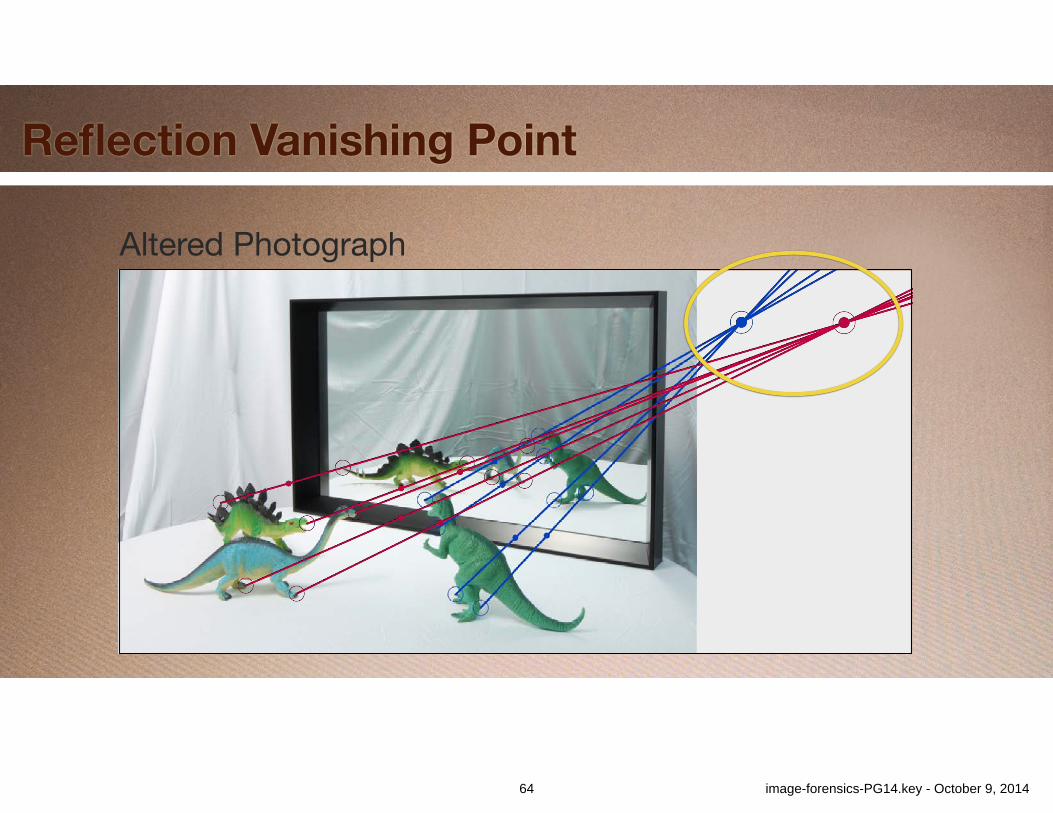
Reflection Vanishing Point
Altered Photograph
64 image-forensics-PG14.key - October 9, 2014
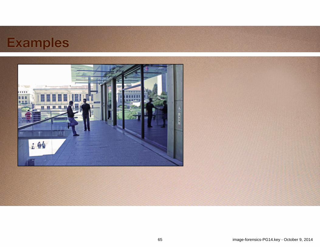
Examples
65 image-forensics-PG14.key - October 9, 2014
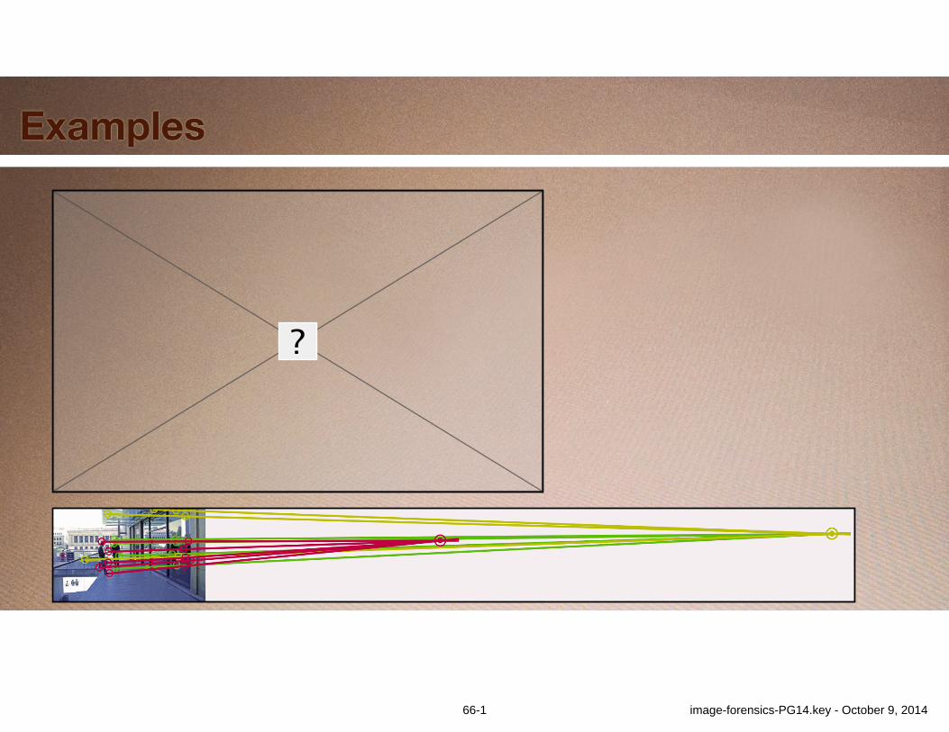
Examples
66-1 image-forensics-PG14.key - October 9, 2014
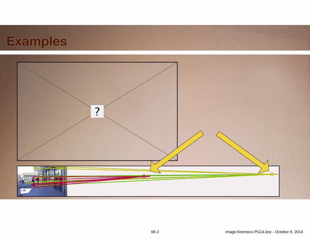
Examples
66-2 image-forensics-PG14.key - October 9, 2014
Examples
Com
posi
te p
hoto
Wor
ld N
ews,
cop
yrig
ht 2
006.
67 image-forensics-PG14.key - October 9, 2014
Examples
Com
posi
te p
hoto
Wor
ld N
ews,
cop
yrig
ht 2
006.
68-1 image-forensics-PG14.key - October 9, 2014
Examples
Com
posi
te p
hoto
Wor
ld N
ews,
cop
yrig
ht 2
006.
68-2 image-forensics-PG14.key - October 9, 2014
Examples
Phot
o by
Ale
xi L
ubom
irski
, “Th
e Sa
int a
nd th
e Si
nner
,” co
pyrig
ht 2
009.
69 image-forensics-PG14.key - October 9, 2014
Examples
Phot
o by
Ale
xi L
ubom
irski
, “Th
e Sa
int a
nd th
e Si
nner
,” co
pyrig
ht 2
009.
70-1 image-forensics-PG14.key - October 9, 2014

Examples
Phot
o by
Ale
xi L
ubom
irski
, “Th
e Sa
int a
nd th
e Si
nner
,” co
pyrig
ht 2
009.
70-2 image-forensics-PG14.key - October 9, 2014

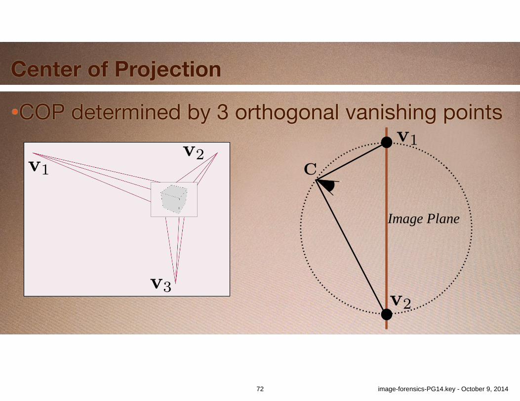
•COP determined by 3 orthogonal vanishing points
Center of Projection
71-1 image-forensics-PG14.key - October 9, 2014

•COP determined by 3 orthogonal vanishing points
v1v2
v3
Center of Projection
71-2 image-forensics-PG14.key - October 9, 2014
•COP determined by 3 orthogonal vanishing points
v1v2
v3
Center of Projection
v1
v2
Image Plane
C
72 image-forensics-PG14.key - October 9, 2014
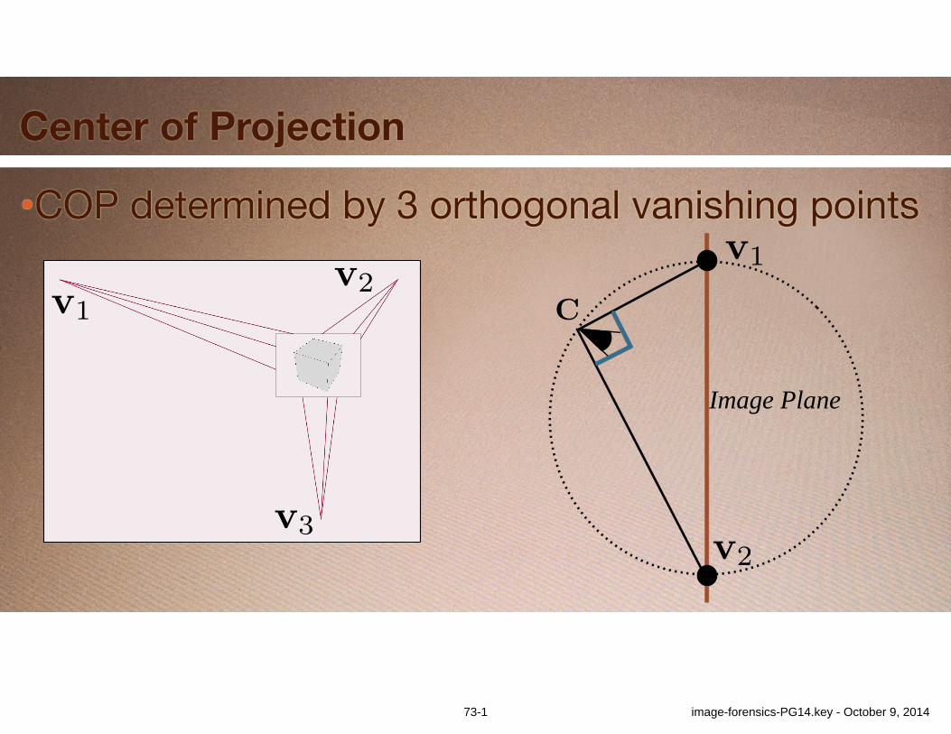
•COP determined by 3 orthogonal vanishing points
v1v2
v3
Center of Projection
v1
v2
Image Plane
C
73-1 image-forensics-PG14.key - October 9, 2014
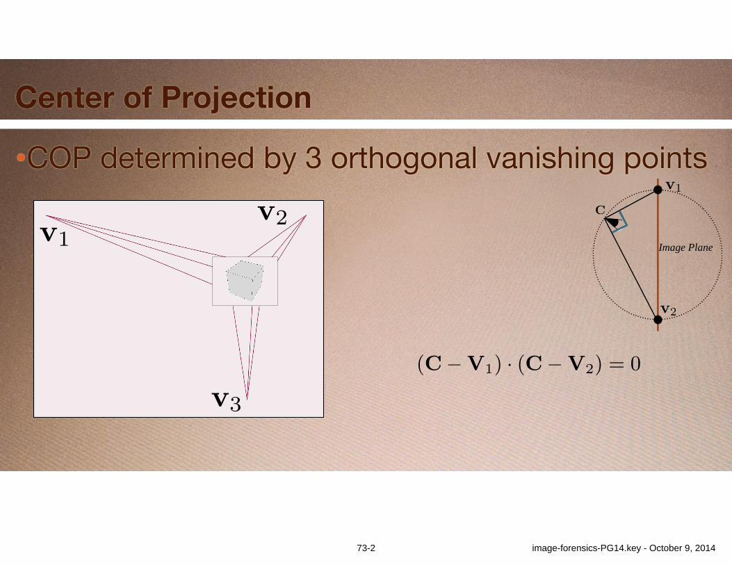
•COP determined by 3 orthogonal vanishing points
v1v2
v3
Center of Projection
Exposing Photo Manipulation with Inconsistent Reflections • 4:9
Composite photo World News, copyright 2006.
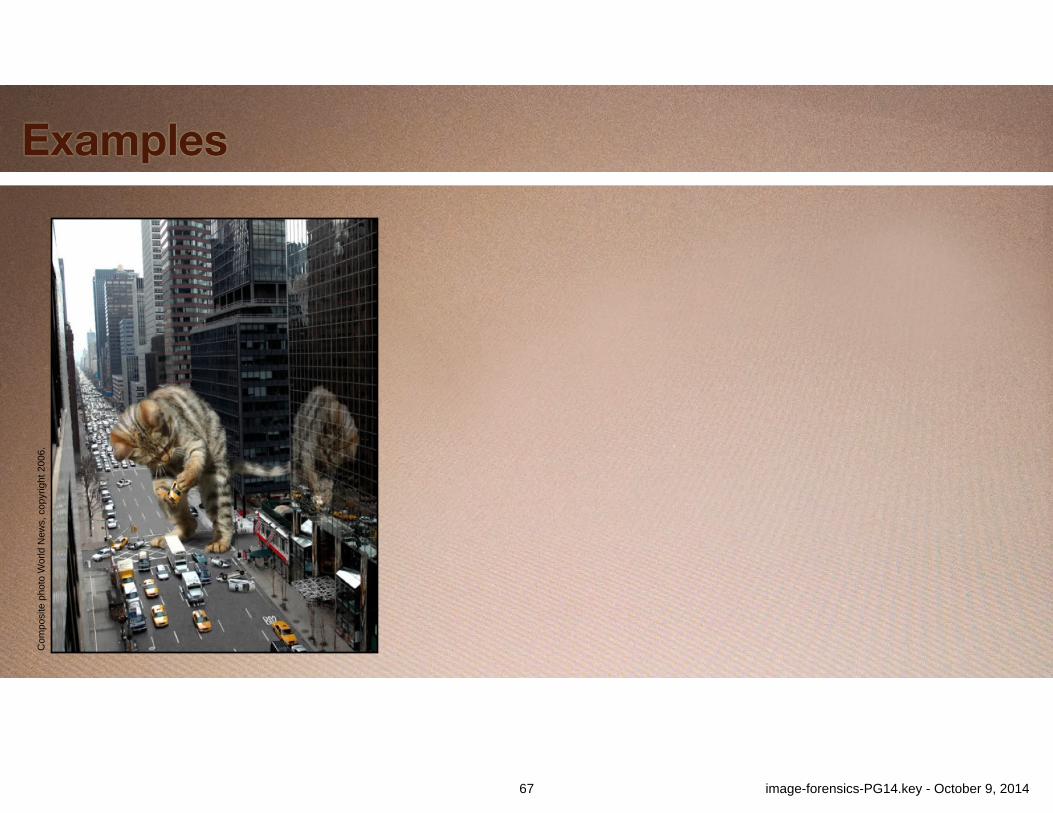
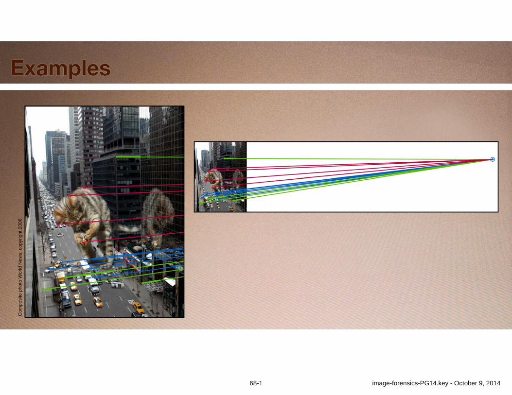
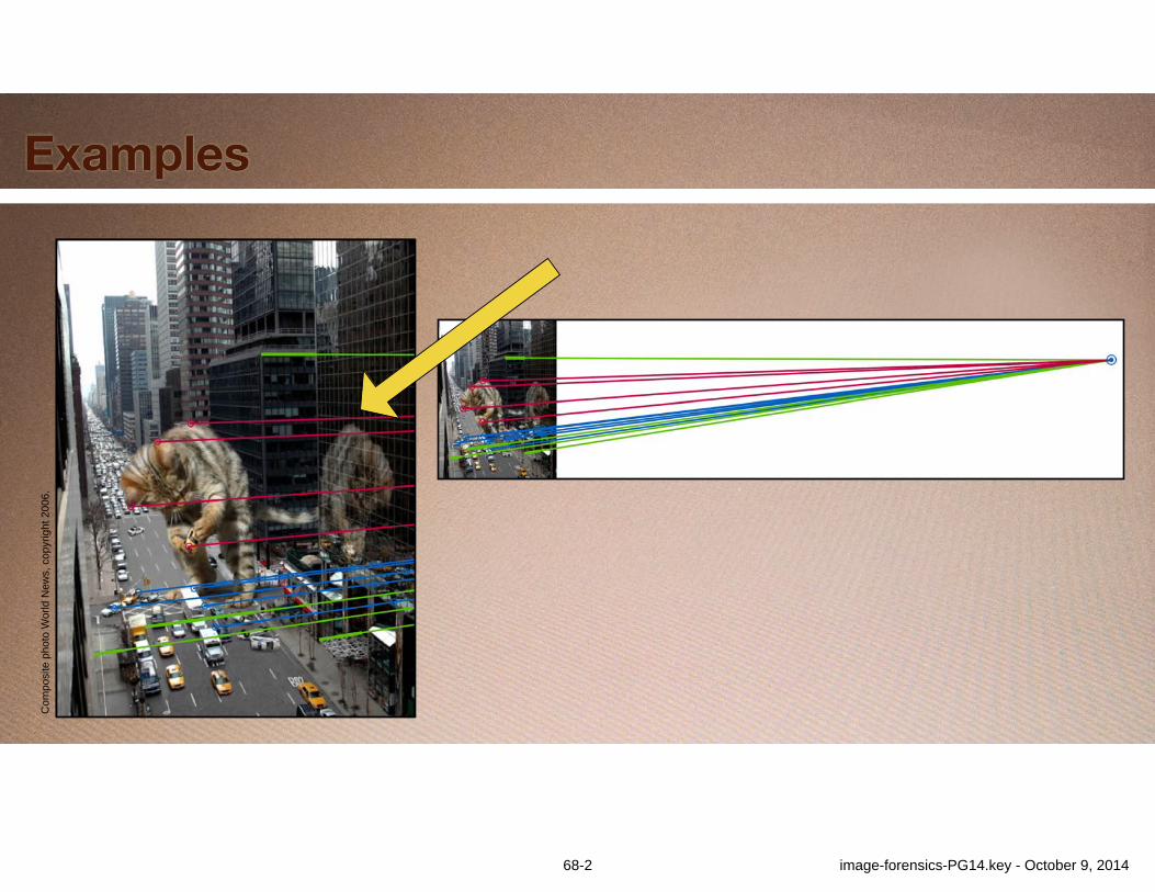
Fig. 12: The image in this figure appeared in news articles on April 1 of2006 and depicts an improbable scenario. Blue lines connect scene featureswith their corresponding reflections in the building windows. Green lineshighlight linear features that should be perpendicular to the building front:an awning, a rooftop, the crosswalk, and a joint in the sidewalk. Extensionsof the blue and green lines yields a single, consistent vanishing point. At-tempting to connect features on the cat to this same vanishing point usingred lines results in those red lines missing the corresponding reflected fea-tures by a large margin indicating that the cat is not consistent with the restof the scene.
applicability of our methods to only certain images, this limitationis expected of any forensic analysis tool. In the cases where ourmethods do apply, they can provide clear and objective evidence ofmanipulation. Due to their geometric nature, they are also insensi-tive to common operations that do not alter scene content such asresampling, color manipulations, and lossy compression.
Mathematica code implementing the methods described here isavailable for use by others under the terms of a BSD open sourcelicense. It can be downloaded from the authors’ website.3
In comparing centers of projection we explicitly considered theuncertainty inherent in trying to select the exact location of a givenfeature. This uncertainty can account for both human error as wellas blurred or partially occluded features. We did not use this sameapproach when testing for the existence of a well-defined reflectionvanishing point because we did not find it to be necessary. However,the same approach could be used in cases where images are highlyblurry or distorted, or where there is reason to suspect human errorin feature location. For the cat image we dealt with the difficultyof finding clear features on the cat by simply establishing that nolocations on the cat’s reflection were consistent with the reflectionvanishing point established by the rest of the scene. A cloud-basedcomparison might be useful in situations were all objects in a scenehave poorly-locatable features.
One potential area of future work is to develop similar methodsfor use with curved surface reflectors. Although very infrequentin natural scenes, man-made environments often contain smooth,curved, and highly specular surfaces such as car bodies, cooking
3http://graphics.berkeley.edu/papers/Obrien-EPM-2012-01
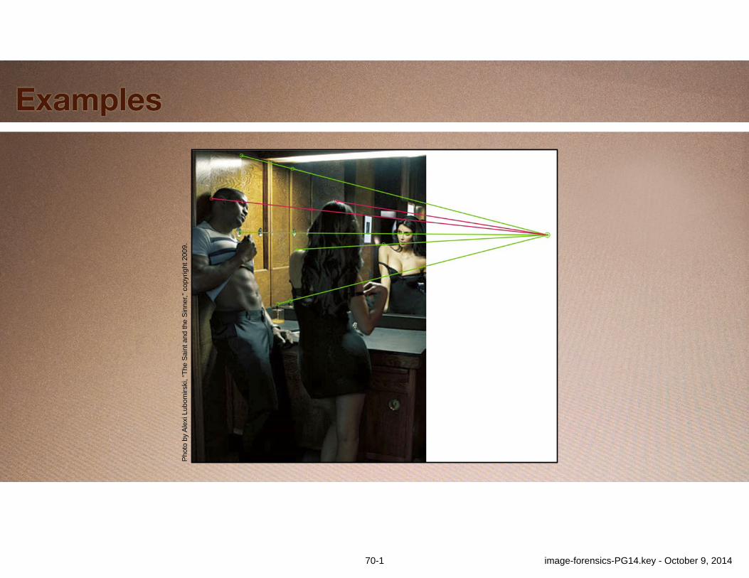
Photo by Alexi Lubomirski, “The Saint and the Sinner,” copyright 2009.
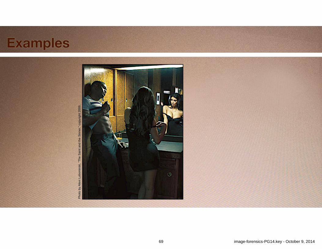
Fig. 13: This image of Reggie Bush and Kim Kardashian appeared in theMarch 2009 issue of GQ Magazine. The green lines establish a reflectionvanishing point for the mirror using several objects in the scene. The redlines reveal that Reggie Bush’s head has been removed from the reflection(it should appear in the blue circle) and that the height of Kim Kardashian’shair has been altered.
pots, windshields, and plastic appliances. One obvious approachwould be to generalize the reflection vanishing point to a curve orsurface patch of points. Unfortunately, our initial experimentationwith this idea indicates that useful application would require an un-reasonable number of corresponding points. Perhaps this limitationcan be overcome or some other approach developed.
As with any testable forensic criteria, an informed forger couldattempt to fool the test. Indeed, one could imagine a tool based onthe analysis in this article that facilitates creating fake reflections.However based on our experience, it is not trivial to create fake re-flections that both look real and that satisfy our criteria. Further, insome instances it is not feasible to create a reflection that wouldlook correct, support the desired fiction of the image, and still passthe tests we have described. For example, in Figure 1 placing thecloser figure’s reflection to make it consistent with the reflectionvanishing point established by the rest of the scene would eithermake the reflection appear unreasonably large or place the otherfigure too far away to be making the hand off. Even when it is fea-sible to create a passable reflection, these tests still create anotherpotential stumbling block that raises the difficulty of creating anundetectable forgery.
APPENDIX
A. COMPUTING THE CENTER OF PROJECTIONThe center of projection, C, for an image where three mutuallyorthogonal vanishing points, V
i
, have been identified must satisfythe following system of quadratic equations:
(C�V1) · (C�V2) = 0 (10)(C�V2) · (C�V3) = 0 (11)(C�V3) · (C�V1) = 0 . (12)
ACM Transactions on Graphics, Vol. 31, No. 1, Article 4, Publication date: January 2012.
v1
v2
Image Plane
C
73-2 image-forensics-PG14.key - October 9, 2014
Exposing Photo Manipulation with Inconsistent Reflections • 4:9
Composite photo World News, copyright 2006.
Fig. 12: The image in this figure appeared in news articles on April 1 of2006 and depicts an improbable scenario. Blue lines connect scene featureswith their corresponding reflections in the building windows. Green lineshighlight linear features that should be perpendicular to the building front:an awning, a rooftop, the crosswalk, and a joint in the sidewalk. Extensionsof the blue and green lines yields a single, consistent vanishing point. At-tempting to connect features on the cat to this same vanishing point usingred lines results in those red lines missing the corresponding reflected fea-tures by a large margin indicating that the cat is not consistent with the restof the scene.
applicability of our methods to only certain images, this limitationis expected of any forensic analysis tool. In the cases where ourmethods do apply, they can provide clear and objective evidence ofmanipulation. Due to their geometric nature, they are also insensi-tive to common operations that do not alter scene content such asresampling, color manipulations, and lossy compression.
Mathematica code implementing the methods described here isavailable for use by others under the terms of a BSD open sourcelicense. It can be downloaded from the authors’ website.3
In comparing centers of projection we explicitly considered theuncertainty inherent in trying to select the exact location of a givenfeature. This uncertainty can account for both human error as wellas blurred or partially occluded features. We did not use this sameapproach when testing for the existence of a well-defined reflectionvanishing point because we did not find it to be necessary. However,the same approach could be used in cases where images are highlyblurry or distorted, or where there is reason to suspect human errorin feature location. For the cat image we dealt with the difficultyof finding clear features on the cat by simply establishing that nolocations on the cat’s reflection were consistent with the reflectionvanishing point established by the rest of the scene. A cloud-basedcomparison might be useful in situations were all objects in a scenehave poorly-locatable features.
One potential area of future work is to develop similar methodsfor use with curved surface reflectors. Although very infrequentin natural scenes, man-made environments often contain smooth,curved, and highly specular surfaces such as car bodies, cooking
3http://graphics.berkeley.edu/papers/Obrien-EPM-2012-01
Photo by Alexi Lubomirski, “The Saint and the Sinner,” copyright 2009.
Fig. 13: This image of Reggie Bush and Kim Kardashian appeared in theMarch 2009 issue of GQ Magazine. The green lines establish a reflectionvanishing point for the mirror using several objects in the scene. The redlines reveal that Reggie Bush’s head has been removed from the reflection(it should appear in the blue circle) and that the height of Kim Kardashian’shair has been altered.
pots, windshields, and plastic appliances. One obvious approachwould be to generalize the reflection vanishing point to a curve orsurface patch of points. Unfortunately, our initial experimentationwith this idea indicates that useful application would require an un-reasonable number of corresponding points. Perhaps this limitationcan be overcome or some other approach developed.
As with any testable forensic criteria, an informed forger couldattempt to fool the test. Indeed, one could imagine a tool based onthe analysis in this article that facilitates creating fake reflections.However based on our experience, it is not trivial to create fake re-flections that both look real and that satisfy our criteria. Further, insome instances it is not feasible to create a reflection that wouldlook correct, support the desired fiction of the image, and still passthe tests we have described. For example, in Figure 1 placing thecloser figure’s reflection to make it consistent with the reflectionvanishing point established by the rest of the scene would eithermake the reflection appear unreasonably large or place the otherfigure too far away to be making the hand off. Even when it is fea-sible to create a passable reflection, these tests still create anotherpotential stumbling block that raises the difficulty of creating anundetectable forgery.
APPENDIX
A. COMPUTING THE CENTER OF PROJECTIONThe center of projection, C, for an image where three mutuallyorthogonal vanishing points, V
i
, have been identified must satisfythe following system of quadratic equations:
(C�V1) · (C�V2) = 0 (10)(C�V2) · (C�V3) = 0 (11)(C�V3) · (C�V1) = 0 . (12)
ACM Transactions on Graphics, Vol. 31, No. 1, Article 4, Publication date: January 2012.
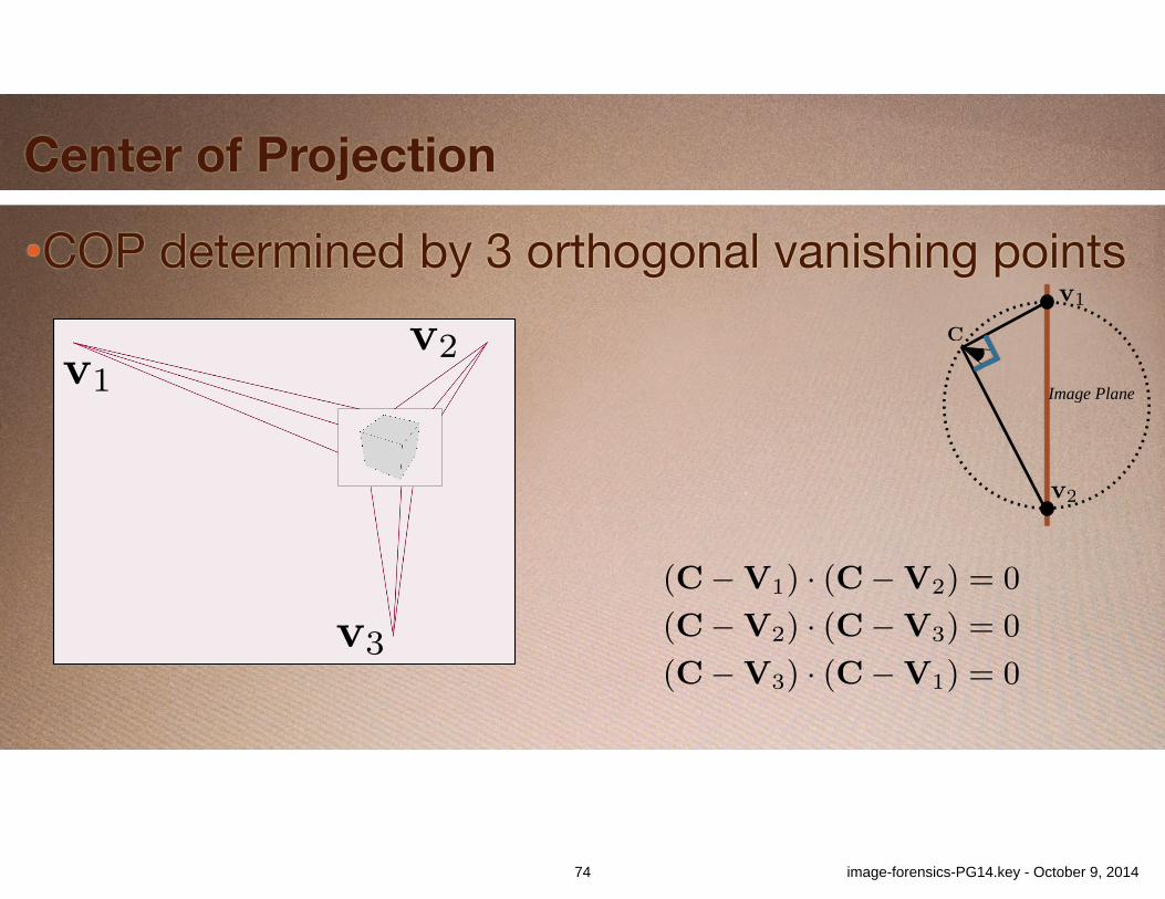
•COP determined by 3 orthogonal vanishing points
Center of Projection
v1v2
v3
v1
v2
Image Plane
C
74 image-forensics-PG14.key - October 9, 2014
Exposing Photo Manipulation with Inconsistent Reflections • 4:9
Composite photo World News, copyright 2006.
Fig. 12: The image in this figure appeared in news articles on April 1 of2006 and depicts an improbable scenario. Blue lines connect scene featureswith their corresponding reflections in the building windows. Green lineshighlight linear features that should be perpendicular to the building front:an awning, a rooftop, the crosswalk, and a joint in the sidewalk. Extensionsof the blue and green lines yields a single, consistent vanishing point. At-tempting to connect features on the cat to this same vanishing point usingred lines results in those red lines missing the corresponding reflected fea-tures by a large margin indicating that the cat is not consistent with the restof the scene.
applicability of our methods to only certain images, this limitationis expected of any forensic analysis tool. In the cases where ourmethods do apply, they can provide clear and objective evidence ofmanipulation. Due to their geometric nature, they are also insensi-tive to common operations that do not alter scene content such asresampling, color manipulations, and lossy compression.
Mathematica code implementing the methods described here isavailable for use by others under the terms of a BSD open sourcelicense. It can be downloaded from the authors’ website.3
In comparing centers of projection we explicitly considered theuncertainty inherent in trying to select the exact location of a givenfeature. This uncertainty can account for both human error as wellas blurred or partially occluded features. We did not use this sameapproach when testing for the existence of a well-defined reflectionvanishing point because we did not find it to be necessary. However,the same approach could be used in cases where images are highlyblurry or distorted, or where there is reason to suspect human errorin feature location. For the cat image we dealt with the difficultyof finding clear features on the cat by simply establishing that nolocations on the cat’s reflection were consistent with the reflectionvanishing point established by the rest of the scene. A cloud-basedcomparison might be useful in situations were all objects in a scenehave poorly-locatable features.
One potential area of future work is to develop similar methodsfor use with curved surface reflectors. Although very infrequentin natural scenes, man-made environments often contain smooth,curved, and highly specular surfaces such as car bodies, cooking
3http://graphics.berkeley.edu/papers/Obrien-EPM-2012-01
Photo by Alexi Lubomirski, “The Saint and the Sinner,” copyright 2009.
Fig. 13: This image of Reggie Bush and Kim Kardashian appeared in theMarch 2009 issue of GQ Magazine. The green lines establish a reflectionvanishing point for the mirror using several objects in the scene. The redlines reveal that Reggie Bush’s head has been removed from the reflection(it should appear in the blue circle) and that the height of Kim Kardashian’shair has been altered.
pots, windshields, and plastic appliances. One obvious approachwould be to generalize the reflection vanishing point to a curve orsurface patch of points. Unfortunately, our initial experimentationwith this idea indicates that useful application would require an un-reasonable number of corresponding points. Perhaps this limitationcan be overcome or some other approach developed.
As with any testable forensic criteria, an informed forger couldattempt to fool the test. Indeed, one could imagine a tool based onthe analysis in this article that facilitates creating fake reflections.However based on our experience, it is not trivial to create fake re-flections that both look real and that satisfy our criteria. Further, insome instances it is not feasible to create a reflection that wouldlook correct, support the desired fiction of the image, and still passthe tests we have described. For example, in Figure 1 placing thecloser figure’s reflection to make it consistent with the reflectionvanishing point established by the rest of the scene would eithermake the reflection appear unreasonably large or place the otherfigure too far away to be making the hand off. Even when it is fea-sible to create a passable reflection, these tests still create anotherpotential stumbling block that raises the difficulty of creating anundetectable forgery.
APPENDIX
A. COMPUTING THE CENTER OF PROJECTIONThe center of projection, C, for an image where three mutuallyorthogonal vanishing points, V
i
, have been identified must satisfythe following system of quadratic equations:
(C�V1) · (C�V2) = 0 (10)(C�V2) · (C�V3) = 0 (11)(C�V3) · (C�V1) = 0 . (12)
ACM Transactions on Graphics, Vol. 31, No. 1, Article 4, Publication date: January 2012.
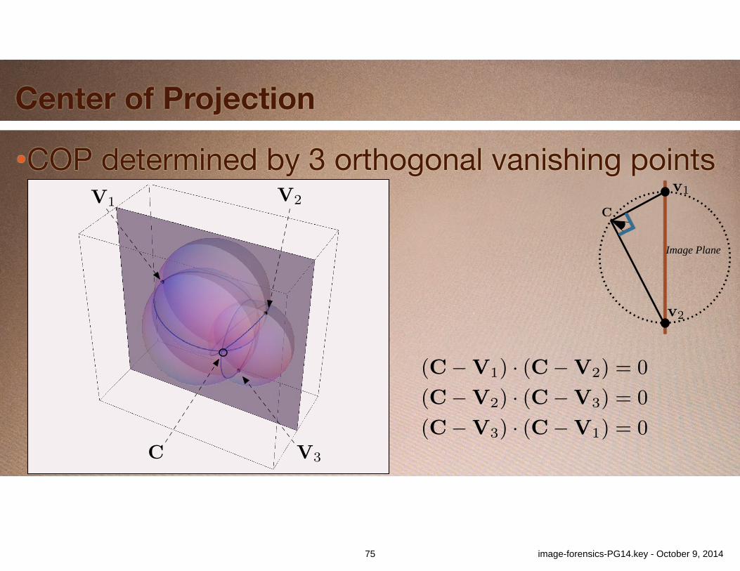
•COP determined by 3 orthogonal vanishing points
Center of Projection
V3
V2V1
C
v1
v2
Image Plane
C
75 image-forensics-PG14.key - October 9, 2014
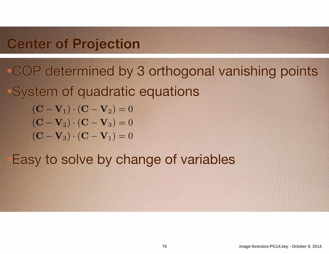
•COP determined by 3 orthogonal vanishing points•System of quadratic equations
•Easy to solve by change of variables
Exposing Photo Manipulation with Inconsistent Reflections • 4:9
Composite photo World News, copyright 2006.
Fig. 12: The image in this figure appeared in news articles on April 1 of2006 and depicts an improbable scenario. Blue lines connect scene featureswith their corresponding reflections in the building windows. Green lineshighlight linear features that should be perpendicular to the building front:an awning, a rooftop, the crosswalk, and a joint in the sidewalk. Extensionsof the blue and green lines yields a single, consistent vanishing point. At-tempting to connect features on the cat to this same vanishing point usingred lines results in those red lines missing the corresponding reflected fea-tures by a large margin indicating that the cat is not consistent with the restof the scene.
applicability of our methods to only certain images, this limitationis expected of any forensic analysis tool. In the cases where ourmethods do apply, they can provide clear and objective evidence ofmanipulation. Due to their geometric nature, they are also insensi-tive to common operations that do not alter scene content such asresampling, color manipulations, and lossy compression.
Mathematica code implementing the methods described here isavailable for use by others under the terms of a BSD open sourcelicense. It can be downloaded from the authors’ website.3
In comparing centers of projection we explicitly considered theuncertainty inherent in trying to select the exact location of a givenfeature. This uncertainty can account for both human error as wellas blurred or partially occluded features. We did not use this sameapproach when testing for the existence of a well-defined reflectionvanishing point because we did not find it to be necessary. However,the same approach could be used in cases where images are highlyblurry or distorted, or where there is reason to suspect human errorin feature location. For the cat image we dealt with the difficultyof finding clear features on the cat by simply establishing that nolocations on the cat’s reflection were consistent with the reflectionvanishing point established by the rest of the scene. A cloud-basedcomparison might be useful in situations were all objects in a scenehave poorly-locatable features.
One potential area of future work is to develop similar methodsfor use with curved surface reflectors. Although very infrequentin natural scenes, man-made environments often contain smooth,curved, and highly specular surfaces such as car bodies, cooking
3http://graphics.berkeley.edu/papers/Obrien-EPM-2012-01
Photo by Alexi Lubomirski, “The Saint and the Sinner,” copyright 2009.
Fig. 13: This image of Reggie Bush and Kim Kardashian appeared in theMarch 2009 issue of GQ Magazine. The green lines establish a reflectionvanishing point for the mirror using several objects in the scene. The redlines reveal that Reggie Bush’s head has been removed from the reflection(it should appear in the blue circle) and that the height of Kim Kardashian’shair has been altered.
pots, windshields, and plastic appliances. One obvious approachwould be to generalize the reflection vanishing point to a curve orsurface patch of points. Unfortunately, our initial experimentationwith this idea indicates that useful application would require an un-reasonable number of corresponding points. Perhaps this limitationcan be overcome or some other approach developed.
As with any testable forensic criteria, an informed forger couldattempt to fool the test. Indeed, one could imagine a tool based onthe analysis in this article that facilitates creating fake reflections.However based on our experience, it is not trivial to create fake re-flections that both look real and that satisfy our criteria. Further, insome instances it is not feasible to create a reflection that wouldlook correct, support the desired fiction of the image, and still passthe tests we have described. For example, in Figure 1 placing thecloser figure’s reflection to make it consistent with the reflectionvanishing point established by the rest of the scene would eithermake the reflection appear unreasonably large or place the otherfigure too far away to be making the hand off. Even when it is fea-sible to create a passable reflection, these tests still create anotherpotential stumbling block that raises the difficulty of creating anundetectable forgery.
APPENDIX
A. COMPUTING THE CENTER OF PROJECTIONThe center of projection, C, for an image where three mutuallyorthogonal vanishing points, V
i
, have been identified must satisfythe following system of quadratic equations:
(C�V1) · (C�V2) = 0 (10)(C�V2) · (C�V3) = 0 (11)(C�V3) · (C�V1) = 0 . (12)
ACM Transactions on Graphics, Vol. 31, No. 1, Article 4, Publication date: January 2012.
Center of Projection
76 image-forensics-PG14.key - October 9, 2014
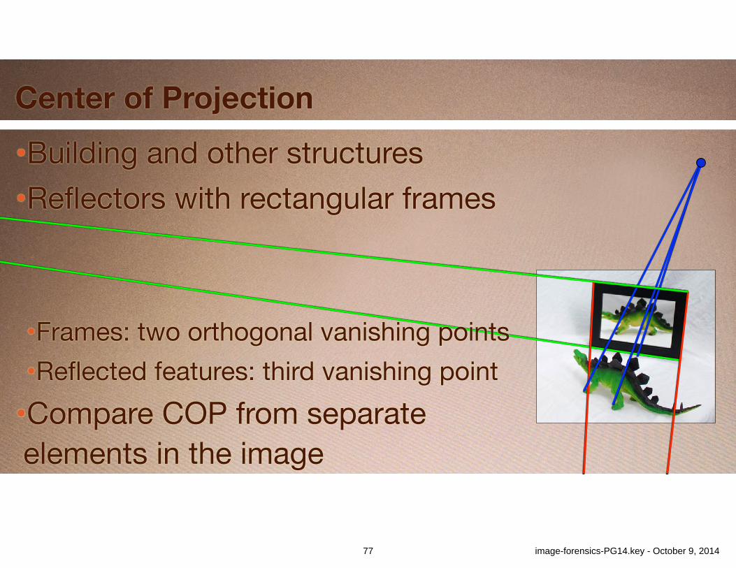
Center of Projection
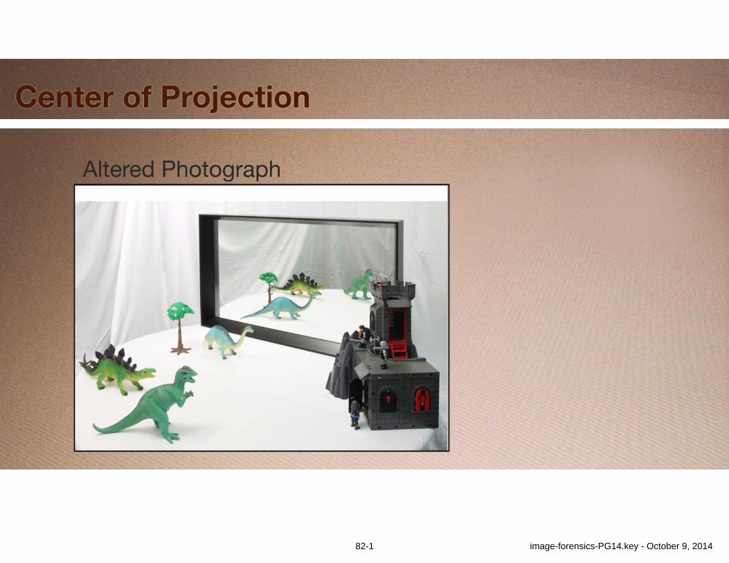
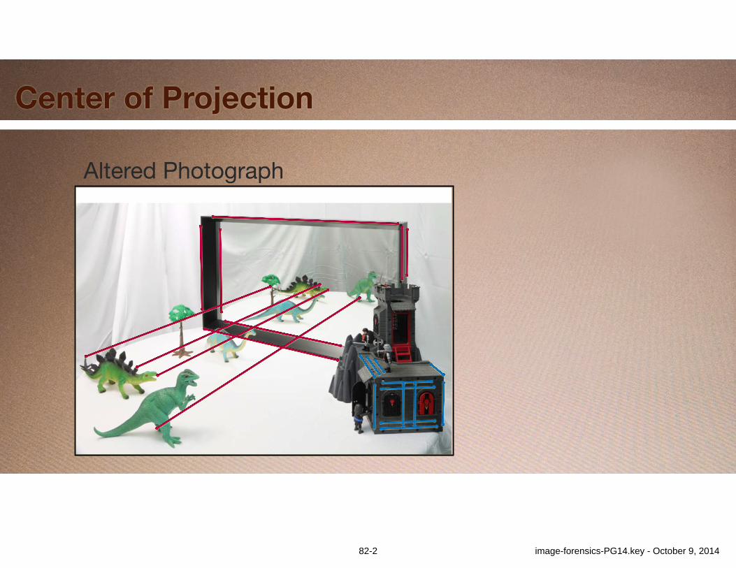
•Building and other structures•Reflectors with rectangular frames !
!
•Frames: two orthogonal vanishing points•Reflected features: third vanishing point•Compare COP from separate elements in the image
77 image-forensics-PG14.key - October 9, 2014

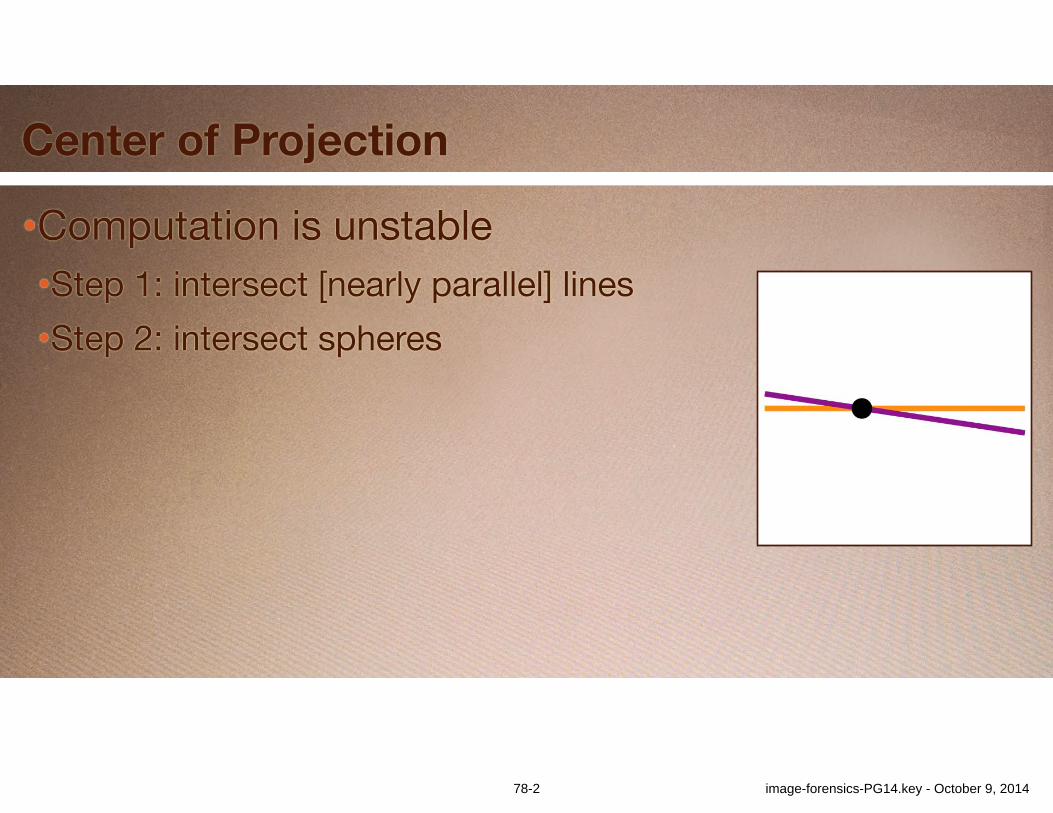
Center of Projection
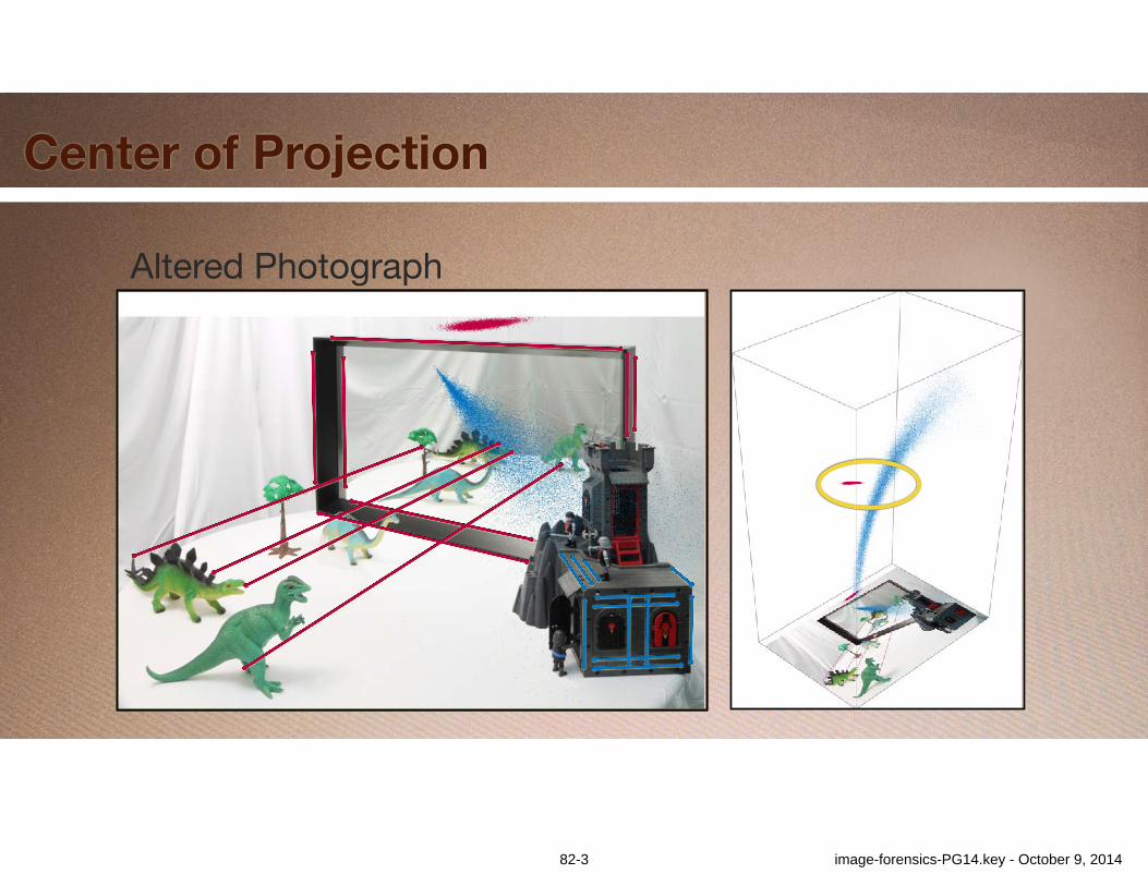
•Computation is unstable•Step 1: intersect [nearly parallel] lines•Step 2: intersect spheres
78-1 image-forensics-PG14.key - October 9, 2014
Center of Projection
•Computation is unstable•Step 1: intersect [nearly parallel] lines•Step 2: intersect spheres
78-2 image-forensics-PG14.key - October 9, 2014
Center of Projection
•Computation is unstable•Step 1: intersect [nearly parallel] lines•Step 2: intersect spheres
79-1 image-forensics-PG14.key - October 9, 2014

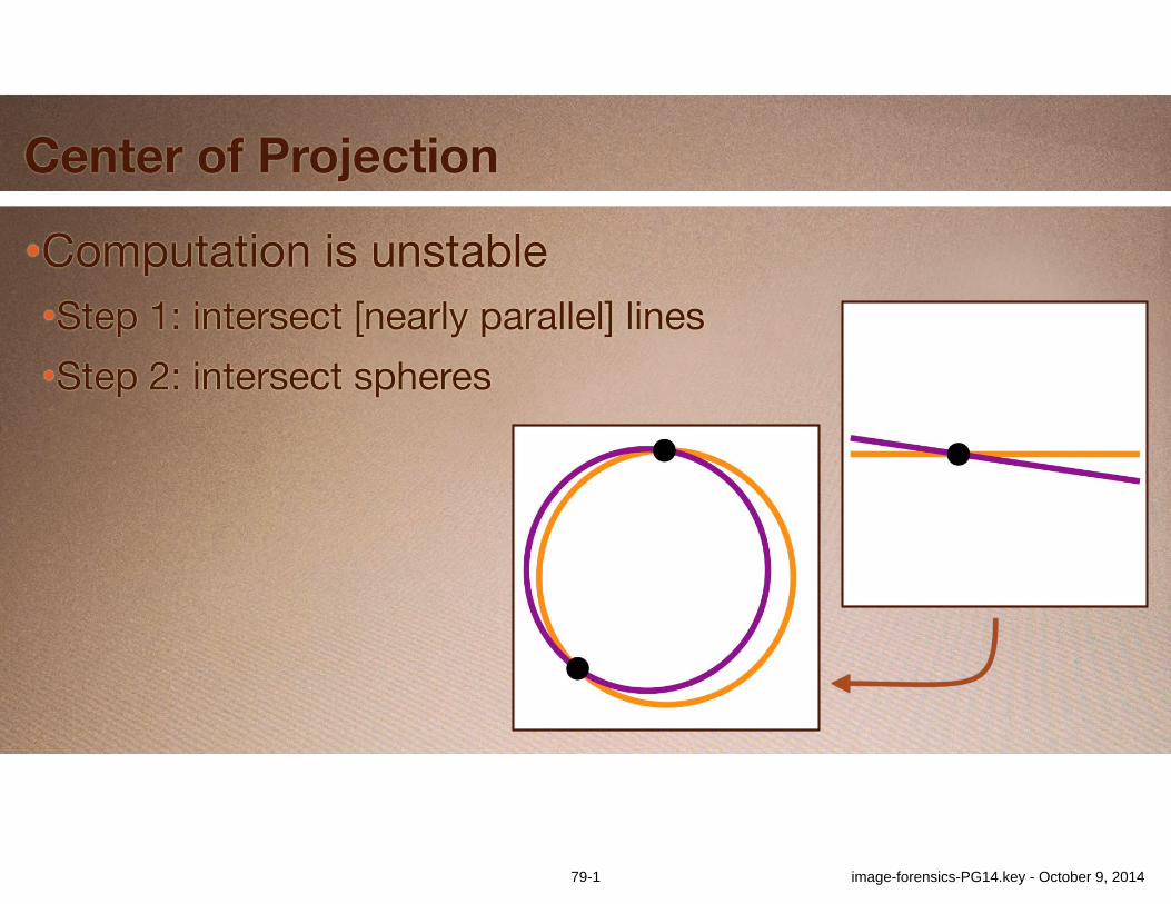
Center of Projection
•Computation is unstable•Step 1: intersect [nearly parallel] lines•Step 2: intersect spheres
79-2 image-forensics-PG14.key - October 9, 2014

Center of Projection
•Computation is unstable•Step 1: intersect [nearly parallel] lines•Step 2: intersect spheres
• “Instability squared”
79-3 image-forensics-PG14.key - October 9, 2014
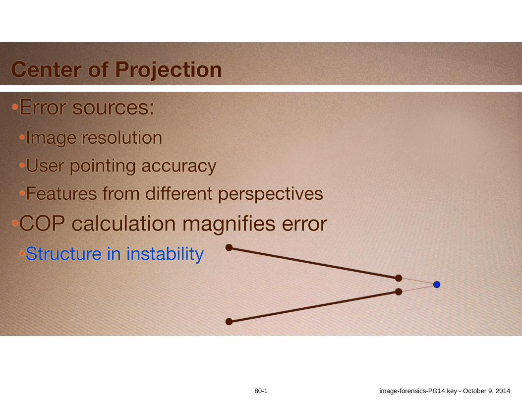
•Error sources:•Image resolution•User pointing accuracy•Features from different perspectives•COP calculation magnifies error•Structure in instability
Center of Projection
80-1 image-forensics-PG14.key - October 9, 2014
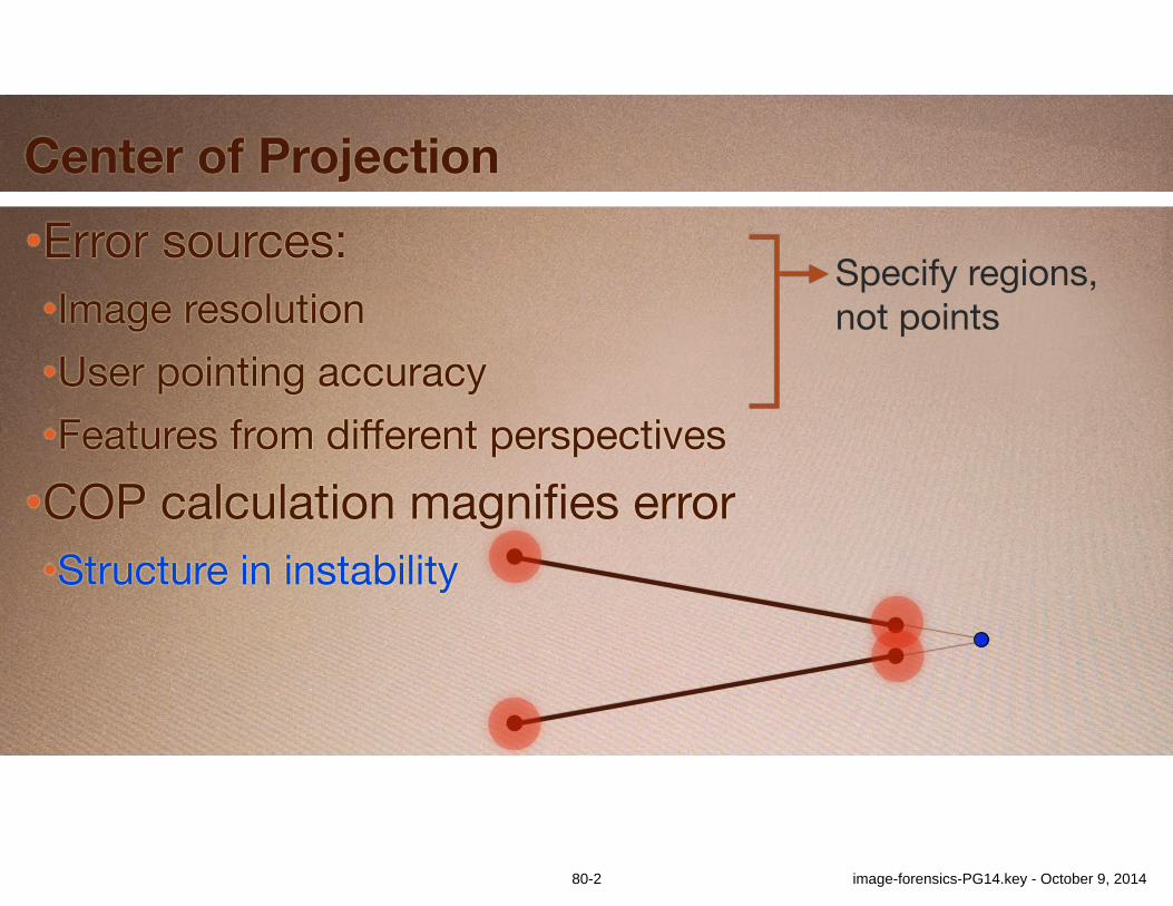
•Error sources:•Image resolution•User pointing accuracy•Features from different perspectives•COP calculation magnifies error•Structure in instability
Center of Projection
Specify regions, not points
80-2 image-forensics-PG14.key - October 9, 2014
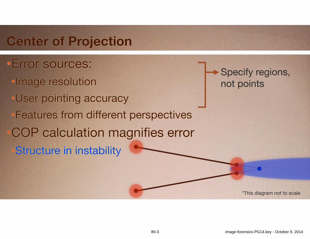
•Error sources:•Image resolution•User pointing accuracy•Features from different perspectives•COP calculation magnifies error•Structure in instability
Center of Projection
*This diagram not to scale
Specify regions, not points
80-3 image-forensics-PG14.key - October 9, 2014
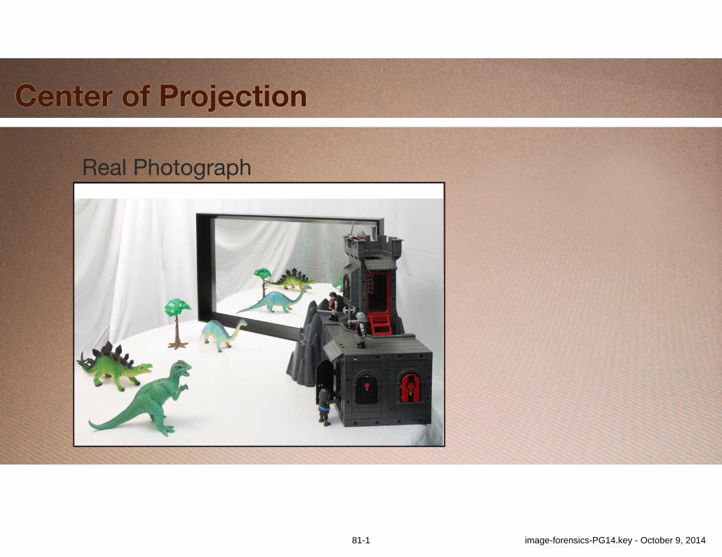
Center of Projection
Real Photograph
81-1 image-forensics-PG14.key - October 9, 2014
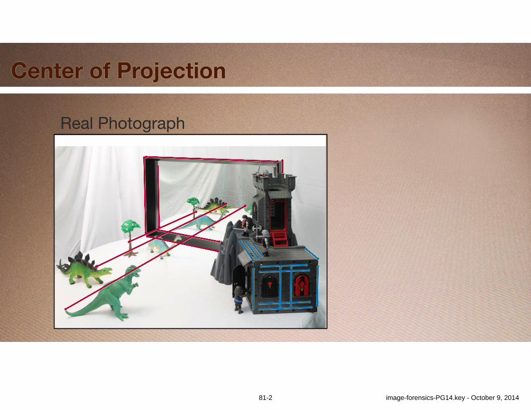
Center of Projection
Real Photograph
81-2 image-forensics-PG14.key - October 9, 2014
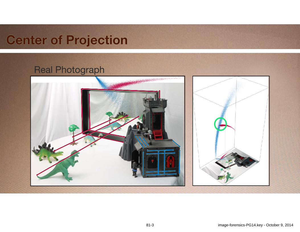
Center of Projection
Real Photograph
81-3 image-forensics-PG14.key - October 9, 2014
Center of Projection
Altered Photograph
82-1 image-forensics-PG14.key - October 9, 2014
Center of Projection
Altered Photograph
82-2 image-forensics-PG14.key - October 9, 2014
Center of Projection
Altered Photograph
82-3 image-forensics-PG14.key - October 9, 2014
Center of Projection
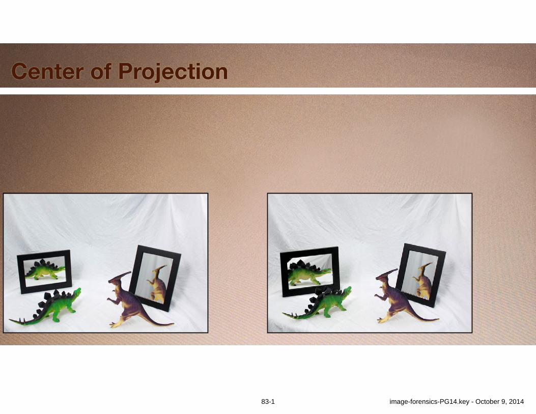
83-1 image-forensics-PG14.key - October 9, 2014
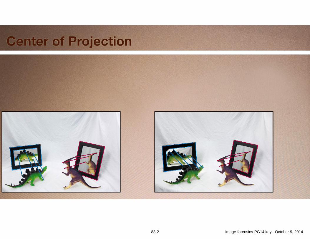
Center of Projection
83-2 image-forensics-PG14.key - October 9, 2014
Center of Projection
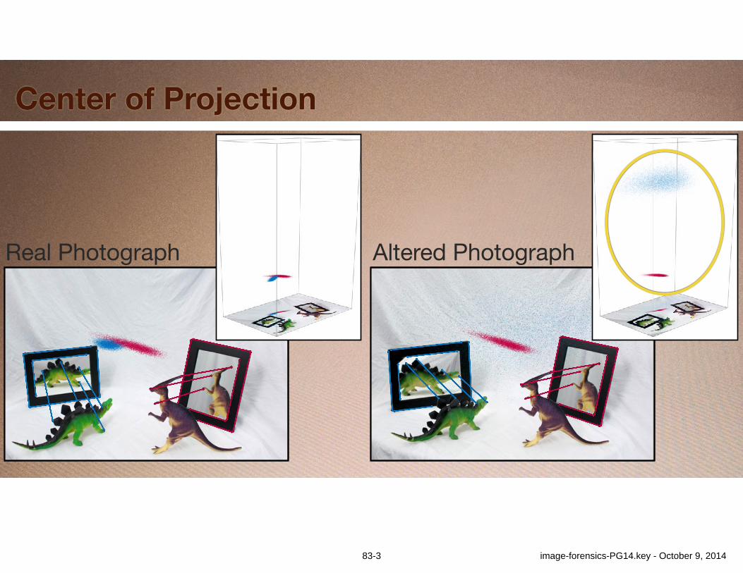
Altered PhotographReal Photograph
83-3 image-forensics-PG14.key - October 9, 2014
CoP from Faces
Work in progress
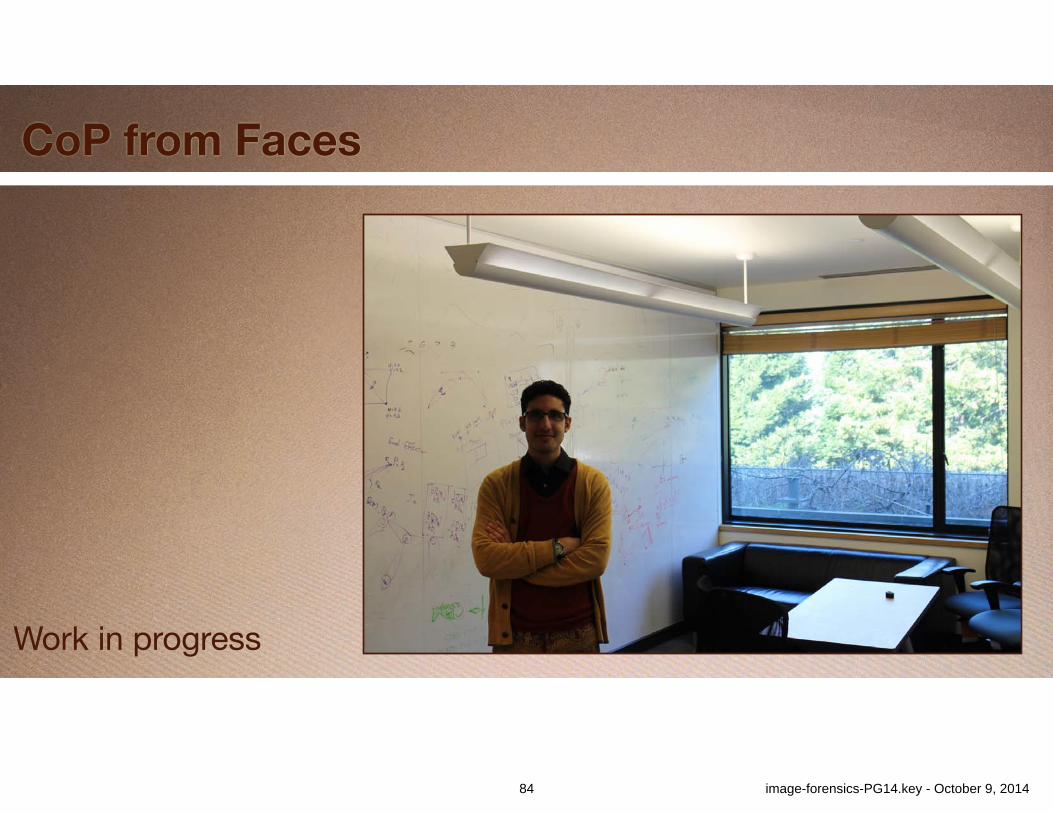
84 image-forensics-PG14.key - October 9, 2014
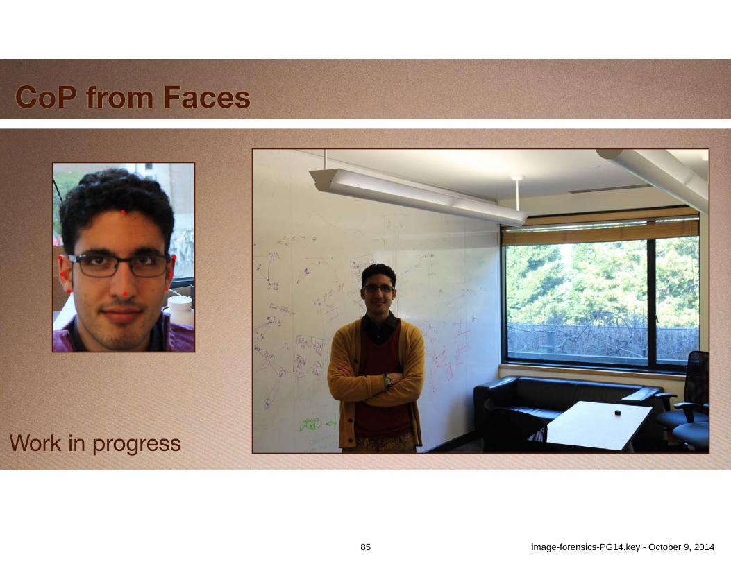
CoP from Faces
Work in progress
85 image-forensics-PG14.key - October 9, 2014

CoP from Faces
Work in progress
86 image-forensics-PG14.key - October 9, 2014
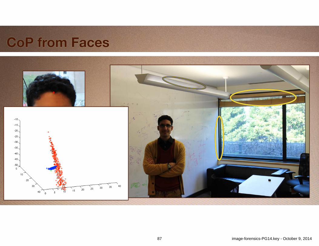
CoP from Faces
Work in progress
87 image-forensics-PG14.key - October 9, 2014
Summary
•Geometric Image Forensics•Human annotation•Computer analysis•Part of “analysis toolbox”•Not always applicable•Together make forgery more difficult•Constrain image content
88 image-forensics-PG14.key - October 9, 2014
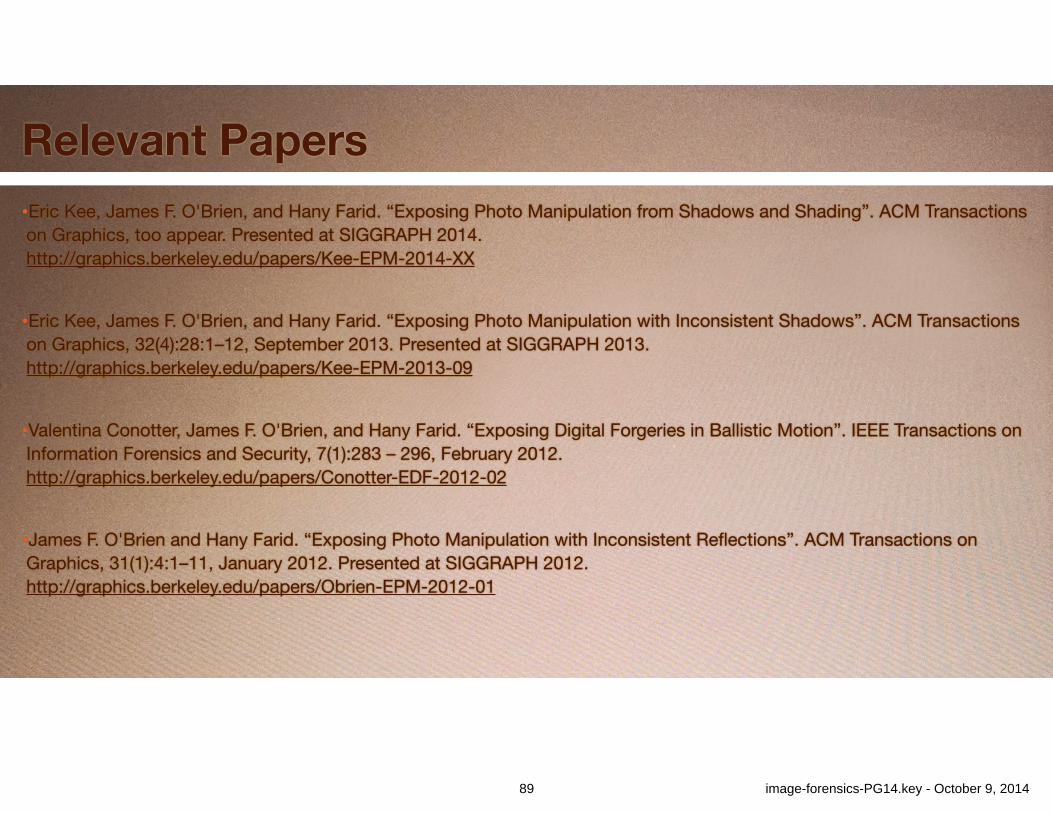
Relevant Papers•Eric Kee, James F. O'Brien, and Hany Farid. “Exposing Photo Manipulation from Shadows and Shading”. ACM Transactions on Graphics, too appear. Presented at SIGGRAPH 2014.http://graphics.berkeley.edu/papers/Kee-EPM-2014-XX!
•Eric Kee, James F. O'Brien, and Hany Farid. “Exposing Photo Manipulation with Inconsistent Shadows”. ACM Transactions on Graphics, 32(4):28:1–12, September 2013. Presented at SIGGRAPH 2013. http://graphics.berkeley.edu/papers/Kee-EPM-2013-09!
•Valentina Conotter, James F. O'Brien, and Hany Farid. “Exposing Digital Forgeries in Ballistic Motion”. IEEE Transactions on Information Forensics and Security, 7(1):283 – 296, February 2012. http://graphics.berkeley.edu/papers/Conotter-EDF-2012-02!
•James F. O'Brien and Hany Farid. “Exposing Photo Manipulation with Inconsistent Reflections”. ACM Transactions on Graphics, 31(1):4:1–11, January 2012. Presented at SIGGRAPH 2012. http://graphics.berkeley.edu/papers/Obrien-EPM-2012-01
89 image-forensics-PG14.key - October 9, 2014

Thank You
90 image-forensics-PG14.key - October 9, 2014

![As-Rigid-As-Possible Shape Manipulationtakeo/papers/rigid.pdf · Graphics]: Computational Geometry and Object Modeling – Geometric algorithms. Keywords: Shape Manipulation, Deformation,](https://img.pdfslide.us/doc/110x75/5f4fa3fc78766128256cac7a/as-rigid-as-possible-shape-manipulation-takeopapersrigidpdf-graphics-computational.jpg)