Embed Size (px)
Citation preview

Table of Contents
Pre-Delivery Instructions1206NT
End-Wheel, No-Till Drill
Manufacturing, Inc.www.greatplainsmfg.com
Read this manual entirely. When you see this symbol, the subsequentinstructions and warnings are serious - follow without exception.Your life and the lives of others depend on it!
Illustrations may show optional equipment not supplied with standard unit.
© Copyright 2017 Printed 06/12/2017 150-166Q
EN
Table of Contents
ORIGINAL INSTRUCTIONS EN

Table of Contents
Table of Contents

1206NT Cover iii
Table of Contents
Important Safety Information.................................................1Safety Decals ....................................................................5
Introduction.............................................................................6Description of Unit .............................................................6Models covered .................................................................6
Document Family ......................................................6Using This Manual.............................................................7Definitions..........................................................................7
Preparation..............................................................................8Tools Required ..................................................................8Assembly and Setup Assistance .......................................8
Unloading the Truck ...............................................................9Assembly...............................................................................10
Tools Required ................................................................10Pre-Assembly Checklist...................................................10Removing Tongue, if Shipped Attached ..........................11Prepare Folding Tongue..................................................11Install Tongue ..................................................................12Lighting and Hydraulic Hoses..........................................13
Route Hoses and Harnesses ...................................13Setup......................................................................................15
Hitching Tractor to Drill....................................................15Clevis Hitch Assembly..............................................15Adjust Hitch Height...................................................15Hitch Heights............................................................16Adjusting Either Hitch...............................................17Safety Chain.............................................................18Jack Storage ............................................................18Hydraulic Hookup.....................................................19Transport Lift Cylinder Flow Setting .........................19Bleeding Hydraulics .................................................20Rephasing Cylinders ................................................21Leveling Drill.............................................................21
Appendix ...............................................................................22Tire Size and Pressure....................................................22Torque Values Chart .......................................................22Hydraulic Connectors and Torque...................................23
2017-06-12 Cover 150-166Q
© Copyright 2012, 2014, 2015, 2017 All rights Reserved
Great Plains Manufacturing, Inc. provides this publication “as is” without warranty of any kind, either expressed or implied. While every precaution has beentaken in the preparation of this manual, Great Plains Manufacturing, Inc. assumes no responsibility for errors or omissions. Neither is any liability assumed fordamages resulting from the use of the information contained herein. Great Plains Manufacturing, Inc. reserves the right to revise and improve its products asit sees fit. This publication describes the state of this product at the time of its publication, and may not reflect the product in the future.
Trademarks of Great Plains Manufacturing, Inc. include: AccuShot, Max-Chisel, Row-Pro, Singulator Plus, Short Disk, Swath Command, Terra-Tine, Ultra-Chisel, and X-Press.
Registered Trademarks of Great Plains Manufacturing, Inc. include: Air-Pro, Clear-Shot, Discovator, Great Plains, Land Pride, MeterCone, Nutri-Pro, Seed-Lok, Solid Stand, Terra-Guard, Turbo-Chisel, Turbo-Chopper, Turbo-Max, Turbo-Till, Ultra-Till, Whirlfilter, and Yield-Pro.
Brand and Product Names that appear and are owned by others are trademarks of their respective owners.Printed in the United States of America

Cover
Cover

1206NT Table of Contents 1
Important Safety Information
Look for Safety SymbolThe SAFETY ALERT SYMBOL indicates there is apotential hazard to personal safety involved and extrasafety precaution must be taken. When you see thissymbol, be alert and carefully read the message thatfollows it. In addition to design and configuration ofequipment, hazard control and accident prevention aredependent upon the awareness, concern, prudence andproper training of personnel involved in the operation,transport, maintenance and storage of equipment.
Be Aware of Signal WordsSignal words designate a degree or level of hazardseriousness.
DANGER indicates an imminently hazardous situationwhich, if not avoided, will result in death or serious injury.This signal word is limited to the most extreme situations,typically for machine components that, for functionalpurposes, cannot be guarded.
WARNING indicates a potentially hazardous situationwhich, if not avoided, could result in death or seriousinjury, and includes hazards that are exposed whenguards are removed. It may also be used to alert againstunsafe practices.
CAUTION indicates a potentially hazardous situationwhich, if not avoided, may result in minor or moderateinjury. It may also be used to alert against unsafepractices.
Prepare for Emergencies Be prepared if a fire starts
Keep a first aid kit and fire extinguisher handy.
Keep emergency numbers for doctor, ambulance, hospitaland fire department near phone.
Be Familiar with Safety Decals Read and understand “Safety Decals” on page 5,
thoroughly.
Read all instructions noted on the decals.
Keep decals clean. Replace damaged, faded and illegibledecals.
2017-06-12 Table of Contents 150-166Q

1206NT Table of Contents Important Safety Information 2
Wear Protective Equipment Wear protective clothing and equipment.
Wear clothing and equipment appropriate for the job.Avoid loose-fitting clothing.
Because prolonged exposure to loud noise can causehearing impairment or hearing loss, wear suitablehearing protection such as earmuffs or earplugs.
Because operating equipment safely requires your fullattention, avoid wearing radio headphones whileoperating machinery.
Avoid High Pressure FluidsEscaping fluid under pressure can penetrate the skin,causing serious injury.
Avoid the hazard by relieving pressure beforedisconnecting hydraulic lines.
Use a piece of paper or cardboard, NOT BODY PARTS, tocheck for suspected leaks.
Wear protective gloves and safety glasses or goggles whenworking with hydraulic systems.
If an accident occurs, seek immediate medical assistancefrom a physician familiar with this type of injury.
If an accident occurs, see a doctor immediately. Any fluidinjected into the skin must be surgically removed within afew hours or gangrene can result.
Handle Chemicals Properly Read and follow chemical manufacturer’s instructions.
Wear protective clothing.
Handle all chemicals with care.
Agricultural chemicals can be dangerous. Improper usecan seriously injure persons, animals, plants, soil andproperty.
Inhaling smoke from any type of chemical fire is a serioushealth hazard.
Store or dispose of unused chemicals as specified by thechemical manufacturer.
Immediately and thoroughly flush any area of the bodythat is contaminated by chemicals.
If chemical is swallowed, carefully follow the chemicalmanufacturer’s recommendations and consult with adoctor.
If persons are exposed to a chemical in a way that couldaffect their health, consult a doctor immediately with thechemical label or container in hand. Any delay couldcause serious illness or death.
Dispose of empty chemical containers properly. By lawrinsing of the used chemical container must be repeatedthree times. Puncture the container to prevent future use.An alternative is to jet-rinse or pressure rinse thecontainer.
After working with chemicals, wash hands and face beforeeating. Shower when application is completed for the day.
Never wash out the tanks within 100 feet (30m) of anyfreshwater source or in a car wash.
Rinse out the tank. Apply rinse water on last field treated.
2017-06-12 Table of Contents 150-166Q

1206NT Table of Contents Important Safety Information 3
Keep Riders Off MachineryRiders obstruct the operator’s view. Riders could bestruck by foreign objects or thrown from the machine.
Never allow children to operate equipment.
Keep all bystanders away from machine during operation.
Use Safety Lights and DevicesSlow-moving tractors and towed implements can createa hazard when driven on public roads. They are difficultto see, especially at night.
Use flashing warning lights and turn signals wheneverdriving on public roads.
Use lights and devices provided with implement
Transport Machinery SafelyMaximum transport speed for implement is20 mph(32 km/h). Some rough terrains require a slower speed.Sudden braking can cause a towed load to swerve andupset.
Do not exceed 20 mph (32 km/h). Never travel speedswhich do not allow adequate control of steering andstopping. Reduce speed if towed load is not equipped withbrakes.
Comply with state and local laws.
Do not tow an implement that, when fully loaded, weighsmore than 1.5 times the weight of towing vehicle.
Carry reflectors or flags to mark drill in case ofbreakdown on the road.
Keep clear of overhead power lines and otherobstructions when transporting. Refer to transportdimensions in the Operator’s Manual.
2017-06-12 Table of Contents 150-166Q

1206NT Table of Contents Important Safety Information 4
Shutdown and Storage Lower drill, put tractor in park, turn off engine, and
remove the key.
Secure drill using blocks and supports provided.
Detach and store drill in an area where children normallydo not play.Use A Safety Chain
Use a safety chain to help control drawn machineryshould it separate from tractor drawbar.
Use a chain with a strength rating equal to or greater thanthe gross weight of towed machinery.
Attach chain to tractor drawbar support or other specifiedanchor location. Allow only enough slack in chain topermit turning.
Replace chain if any links or end fittings are broken,stretched or damaged.
Do not use safety chain for towing.
Tire SafetyTire changing can be dangerous and must be performedby trained personnel using correct tools and equipment.
When inflating tires, use a clip-on chuck and extensionhose long enough for you to stand to one side–not in frontof or over tire assembly. Use a safety cage if available.
When removing and installing wheels, use wheel-handlingequipment adequate for weight involved.
Practice Safe Maintenance Understand procedure before doing work. Use proper
tools and equipment. Refer to this manual for additionalinformation.
Work in a clean, dry area.
Lower the drill, put tractor in park, turn off engine, andremove key before performing maintenance.
Make sure all moving parts have stopped and all systempressure is relieved.
Allow drill to cool completely.
Disconnect battery ground cable (-) before servicing oradjusting electrical systems or before welding on drill.
Inspect all parts. Make sure parts are in good conditionand installed properly.
Remove buildup of grease, oil, or debris.
Remove all tools and unused parts from drill beforeoperation.
2017-06-12 Table of Contents 150-166Q

1206NT Table of Contents Important Safety Information 5
Safety At All TimesThoroughly read and understand the instructions in thismanual before operation. Read all instructions noted onthe safety decals.
Be familiar with all drill functions.
Operate machinery from the driver’s seat only.
Do not leave drill unattended with tractor engine running.
Do not dismount a moving tractor. Dismounting a movingtractor could cause serious injury or death.
Do not stand between the tractor and drill duringhitching.
Keep hands, feet and clothing away from power-drivenparts.
Wear snug-fitting clothing to avoid entanglement withmoving parts.
Watch out for wires, trees, etc., when folding and raisingdrill. Make sure all persons are clear of working area.
Do not turn tractor too tightly, causing drill to ride up onwheels. This could cause personal injury or equipmentdamage.
Safety DecalsSafety Reflectors and DecalsYour implement comes equipped with all lights, safetyreflectors and decals in place. They were designed tohelp you safely operate your implement.
Read and follow decal directions.
Keep lights in operating condition.
Keep all safety decals clean and legible.
Replace all damaged or missing decals. Order new decalsfrom your Great Plains dealer. Refer to this section forproper decal placement.
When ordering new parts or components, also requestcorresponding safety decals.To install new decals:
To install new decals:
1. Clean the area on which the decal is to be placed.
2. Peel backing from decal. Press firmly on surface,being careful not to cause air bubbles under decal.
2017-06-12 Table of Contents 150-166Q

1206NT Table of Contents 6
Introduction
Great Plains Manufacturing wants you to be satisfiedwith any new machine delivered by the Great PlainsTrucking network. To ease the assembly task andproduce a properly working machine, read this entiremanual before assembling or setting up new equipment.
Description of UnitThe 1206NT No-Till Drill is a 12' grain drill of end wheeldesign which couples Great Plains spring mountedcoulter with a straight arm design of our solid standopener to achieve no-till drilling capabilities. The endwheel design keeps the ground-working components inline with the end wheels for accurate coulter depth andseed placement over uneven terrain and allows the unitto follow field curves without side-loading the openers.
Models covered
Document Family
1206NT-1410 End Wheel No-Till 12 ft. 10 in.1206NT-1808 End Wheel No-Till 12 ft. 8 in.1206NT-1975 End Wheel No-Till 12 ft. 7-1/2 in.1206NT-2007 End Wheel No-Till 12 ft. 7 in.
150-166Q Pre-Delivery Manual (this document)
150-166M Operator Manual
150-166P 1206NT Parts Manual
150-166B Seed Rate Manual
68367
Figure 11206NT No-Till Drill
2017-06-12 Table of Contents 150-166Q

1206NT Table of Contents Introduction 7
Using This ManualThis manual was written to help you assemble andprepare the new machine for the customer. The manualincludes instructions for assembly and setup. Read thismanual and follow the recommendations for safe,efficient and proper assembly and setup.
An operator’s manual is also provided with the newmachine. Read and understand “Important SafetyInformation” and “Operating Instructions” in theoperator’s manual before assembling the machine. As areference, keep the operator’s manual on hand whileassembling.
The information in this manual is current at printing.Some parts may change to assure top performance.
DefinitionsThe following terms are used throughout this manual.
Right and left as used in this manual are determined byfacing the direction the machine will travel while in useunless otherwise stated.
Paragraphs in this format present a crucial point of informationrelated to the current topic.
Read and follow the directions to:- remain safe,- avoid serious damage to equipment and- ensure desired field results.
NOTE:Useful information about the preceding topic.
Further AssistanceFor additional help with understanding these assemblyinstructions or for any other assembly or setup relatedquestions, please contact our service department at thefollowing address:
Great Plains Service Department1525 E. North St.
P.O. Box 5060Salina, KS 67402-5060
Or call us at (800) 270-9302 to speak over the phonewith a service representative.
Copies of this machine’s operator manual are availableby mail or online. Please visit www.greatplainsag.comand follow the product link for information on yourmachine.
2017-06-12 Table of Contents 150-166Q

1206NT Table of Contents 8
Preparation
Step-by-step instructions for assembling the drill begin inthe next section of the manual. Before commencingwork, review the Tools Required and Pre-AssemblyChecklist to make sure you have all necessary parts andequipment.
The drill is shipped via flat bed truck. It is the dealer’sresponsibility to unload the new machine. Unload allequipment before beginning assembly.
The general sequence of work is:
Assembly
a. Unload frame, tongue and accessories from truck.
b. Assemble tongue to mainframe.c. Route hoses and harness.
Setup
a. Adjust hitch height.b. Hitch to tractor.c. Level drill.d. Bleed hydraulics.e. Install accessories and Options.f. Set coulter depth control. (Do not skip this
step!)Tools Required• Lift or overhead hoist with a minimum lifting capacity
of 8000 pounds (3628 kg).• A tractor of sufficient size and horsepower with
remote hydraulics. Refer to “Specifications andCapacities” in the Operator’s Manual.
If the tractor to be used with the drill is not availableduring setup, obtain a measurement of its hitchheight.
• General hand tools
• Jack stands or blocks and safety chain. NOTE:
You need about 1 gallon (3.8 liters) of hydraulic oil torefill the tractor hydraulic reservoir after initialbleeding and cycling of the hydraulic system.
Assembly and Setup AssistanceTo order additional copies of predelivery instructions oroperator’s and parts manuals, write to the followingaddress. Include model numbers in all correspondence.
Do not attempt any assembly work while the drill is on thetruck.
2017-06-12 Table of Contents 150-166Q

1206NT Table of Contents 9
Unloading the Truck
Hoist drill from above.
Do not fork-lift from beneath drill.There are no suitable lift points.
Do not hoist via lugs after tongue is installed in the workingposition.Drill is not balanced at lugs with tongue installed.
1. If the tongue is shipped separate from the machine,use hoist or lift to remove the tongue from truck.
2. Use hoist or lift to remove any accessories fromtruck.
Do not install accessories while the machine is on the truck.
3. Secure lifting lines to the lugs above the lift cylindereyebolts. Prior to tongue installation, these lugspermit nearly level lifting of the drill.
4. Lift drill from truck and lower at assembly point.
5. Remove small parts from main seed box.
21718
Figure 2Hoisting Lines
2017-06-12 Table of Contents 150-166Q

1206NT Table of Contents 10
Assembly
The following headings are step-by-step instructions forassembling the drill. Begin with “Tools Required” and“Pre-Assembly Checklist” to make sure you have allnecessary parts and equipment. Follow each step to makethe job as quick and safe as possible and produce a properlyworking machine.
The drill is shipped via flat bed truck. It is the dealer’sresponsibility to unload the new machine. Unload allequipment before beginning assembly.
Do not attempt any assembly work while the machine is on thetruck.
Tools Required• Fork lift, overhead hoist, or loader
• General hand tools.
Pre-Assembly Checklist1. Before assembling, read and understand the safety
information in this book.
2. Have at least two people on hand while assembling.
3. Make sure assembly area is level and free of obstructions(preferably an open concrete area).
4. Have all major components.
5. Have all fasteners and pins shipped with the drill.
If a pre-assembled part or fastener is temporarily removed,remember where it goes. Keep the parts separated.
6. Have a copy of the parts manual on hand. If unsure ofproper placement or use of any part or fastener, refer tothe parts manual.
7. Check that all working parts are moving freely, bolts aretight, and cotter pins are spread.
8. Check for proper tension and alignment on all drivechains.
9. Check that all safety decals and reflectors are locatedcorrectly and legible. Replace if improperly located ordamaged. Refer to “Safety Decals” in the operator’smanual.
10. Inflate tires to recommended pressure as listed in the“Appendix” on page 22. Tighten wheel bolts as specifiedon “Torque Values Chart” on page 22.
PartsManual
2017-06-12 Table of Contents 150-166Q

1206NT Table of Contents Assembly 11
Removing Tongue, if Shipped Attached1. Use hoist or lift to support the front of the drill while
the tongue is being removed and installed.
2. Use hoist or lift to support the tongue (1).
3. A shipping bracket (2) is used to hold the tongue tothe mainframe during shipping. Carefully removeand discard the shipping bracket and the mountinghardware (3).
4. Lower the tongue to the floor so the rear jackmounting tube (4) is on the top of the tongue.
Prepare Folding Tongue1. If tongue is already unfolded, continue at Install
Tongue.
2. Support the forward end of the rear tongue weldment(1) off the ground by at least 6 in. (15cm). Use ahoist line or place a block under it.
3. Remove the locking pin (2) from the folding tongue.
4. Swing the folding tongue forward and secure withbolts (3), lock washers (4), and nuts (5).
5. Install the locking pin in front half of the tongue andthe lock tube (6) on rear tongue weldment. Install thehair pin.
3
1
2
4
36792
Figure 3Removing Tongue from Mainframe
2
3
4
5
28119
6
1
Figure 4Unfolding Tongue
2017-06-12 Table of Contents 150-166Q

1206NT Table of Contents Assembly 12
Install TongueThe following instruction apply to both the standard andthe folding tongue.
1. Remove the six mounting bolts and four U-bolts fromthe tongue.
2. Connect hoist lines (1) at available hitch holes (2),and around rear tongue tube (3), behind brace tubes(4).
Crushing hazard. You may be severely injured by frames if theyfall. Always support frame sections with jack stands or blocksbefore working under frames raised off ground.
3. Align the mounting plate (5) on the tongue with themounting plate (6) on the mainframe. Insert a bolt (7)at the top center hole and secure finger tight withlock washer and nut.
4. Level tongue from side to side relative to mainframe.Install the remainder of the hardware in the centermounting plate. Fasten finger tight.
5. Insert all four U-bolts (8), and install lock washers,and nuts. Fasten finger tight.
6. Tighten the all of the nuts the on the bolts andU-bolts to 265 ft-lb (350 Nm).
7. Remove hair pin and clevis pin from the jack (9).Install the jack on the front jack mounting tube (10).Put the jack in the vertical position and install theclevis pin and hair pin.
8. Crank the jack down just until the weight of theforward end of the tongue is supported by the jack.
9. Remove all lifting equipment and any blocks.
1
24
3
36791
Figure 5Installing Tongue
5
8
7
6
36791
Figure 6Fastening Tongue
9
10
36733
Figure 7Secure Tongue
2017-06-12 Table of Contents 150-166Q

1206NT Table of Contents Assembly 13
Lighting and Hydraulic HosesThe hydraulic hoses are pre-installed on the drill and aretied to the hitch mounting plate.
The lights may be assembled or may be shipped in theseed box or separately to prevent damage to the lightingsystem during transport and loading.
If the drill is delivered with the lights not assembled, the dealermust assemble the lights on the drill prior to selling the drill.
1. At one end of the drill, install a spacer (1), lampbracket (2), and handle (3) using two 1/2-13 x 1 inchbolts (4) and two flange lock nuts (5).
NOTE:Make sure the horizontal flange of the lamp bracket istoward the front of the drill.
2. Install an amber lamp (6) to the bracket with two1/4-20x3/4 inch self tapping screws (7).
3. Install a hose clip (8) to the lamp bracket with a3/8-16x3/4 bolt (9), lock washer (10), and nut (11).
4. Secure the wiring harness to the hose clip.
5. Place a red reflector (12) to the lamp bracket facingrearward.
6. Repeat the procedure for the other amber lamp.
Route Hoses and Harnesses1. Connect the rear lighting harness (1) to the red
lamps under the walkboard and amber lamps.
2. Fasten the module (2) of the middle lighting harness(3) to the tongue with 1/4-20x1 inch bolts (4) andnuts (5). Connect the middle lighting harness to therear wiring harness.
3. Connect the front lighting harness (6) to the middlelighting harness. Use wire ties (7) to fasten the wiringharnesses to the drill.
4. Tape or tie the tractor connector (8) on the frontlighting harness to the hose bundle at thequick-disconnect fittings.
5. Remove the color-coded hose grips beforeattempting to route the hydraulic hoses through thetongue.
2
11
4
3
256
7
68366
1
Figure 8Amber Lamp Installation
9
8
68372
12
10
11
Figure 9Reflector Installation
3
168366A
2
6
7
8
4
5
Figure 10Connect Light Harnesses
2017-06-12 Table of Contents 150-166Q

1206NT Table of Contents Assembly 14
6. Once hydraulic hoses are routed through the tongue,attach color-coded grips to the correct hydraulichose. Retract grip and hose go to the rod end of thecylinder. Extend grip and hose go to the base end ofthe cylinder.
7. Route the hose and lighting harness bundle (9)under the rear cross-tube of the tongue, into theaccess hole (10), and out the front of the tongue tubenear the hitch.
8. Un-tape/tie the lighting harness. Fasten the lightingconnector and hydraulic quick disconnect fittings tothe holder plate (11).
9 36733
11
10
Figure 11Route Hoses and Harness
2017-06-12 Table of Contents 150-166Q
1206NT Table of Contents 15
Setup
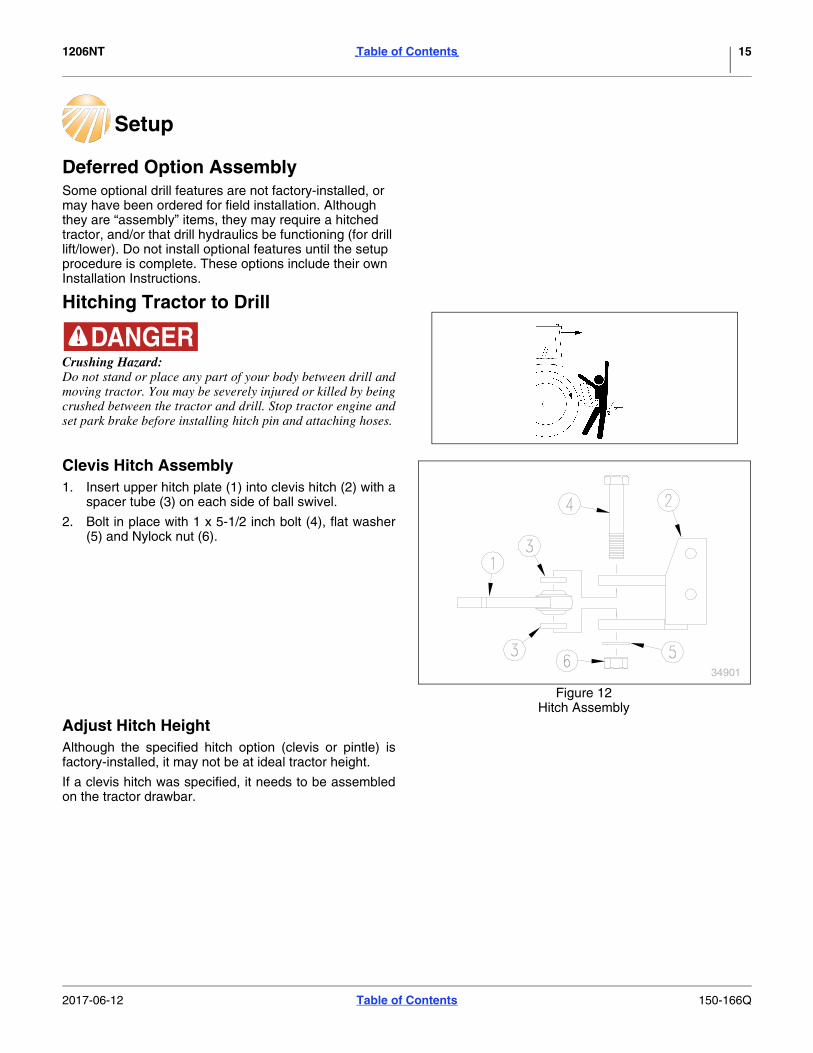
Deferred Option AssemblySome optional drill features are not factory-installed, or may have been ordered for field installation. Although they are “assembly” items, they may require a hitched tractor, and/or that drill hydraulics be functioning (for drill lift/lower). Do not install optional features until the setup procedure is complete. These options include their own Installation Instructions.
Hitching Tractor to Drill
Crushing Hazard:Do not stand or place any part of your body between drill andmoving tractor. You may be severely injured or killed by beingcrushed between the tractor and drill. Stop tractor engine andset park brake before installing hitch pin and attaching hoses.
Clevis Hitch Assembly1. Insert upper hitch plate (1) into clevis hitch (2) with a
spacer tube (3) on each side of ball swivel.
2. Bolt in place with 1 x 5-1/2 inch bolt (4), flat washer(5) and Nylock nut (6).
Adjust Hitch HeightAlthough the specified hitch option (clevis or pintle) isfactory-installed, it may not be at ideal tractor height.
If a clevis hitch was specified, it needs to be assembledon the tractor drawbar.
34901
Figure 12Hitch Assembly
2017-06-12 Table of Contents 150-166Q

1206NT Table of Contents Setup 16
Hitch Heights
The drill operates more effectively if the tongue is level infield position.
The drill needs to be lowered (in field position) for thefollowing measurements and any adjustments.
1. If the intended tractor is available, and has anadjustable or invertible drawbar, set the drawbar tothe operator’s preferred height. If the tractor is notavailable, obtain a measurement of the height:
• clevis hitch: to the bottom surface of the drawbar
• pintle hitch: to the top surface of the lower claw.
2. Use the parking jack to adjust the tongue until it islevel from front to back. If the work surface itself islevel, use a carpenter’s level on top of the tonguetube. When level, the top of the tube is approximately26 34 in. (68cm) above ground at the hitch.
3. Measure from ground to:
• clevis hitch: to the top surface of lower lug
• pintle hitch: to the bottom of ring.
Figure 13Hitch Heights (Tongue Level in Field Position)
28115
Clevis
Pintle
24.0 in61.0 cm 21.0 in
53.4 cm20.0 in50.8cm
18.0 in45.7 cm
17.0 in43.2 cm 14 in
35.6 cm
23.5 in59.7 cm 19.5 in
49.5 cm
20.5 in52.1 cm 17.5 in
44.5 cm16.5 in
41.9 cm 13.5 in34.3 cm
2017-06-12 Table of Contents 150-166Q
1206NT Table of Contents Setup 17
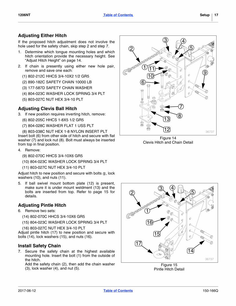
Adjusting Either HitchIf the proposed hitch adjustment does not involve thehole used for the safety chain, skip step 2 and step 7.
1. Determine which tongue mounting holes and whichhitch orientation provide the necessary height. See“Adjust Hitch Height” on page 14.
2. If chain is presently using either new hole pair,remove and save one each:
(1) 802-212C HHCS 3/4-10X2 1/2 GR5
(2) 890-182C SAFETY CHAIN 10000 LB
(3) 177-587D SAFETY CHAIN WASHER
(4) 804-023C WASHER LOCK SPRING 3/4 PLT
(5) 803-027C NUT HEX 3/4-10 PLT
Adjusting Clevis Ball Hitch3. If new position requires inverting hitch, remove:
(6) 802-205C HHCS 1-8X5 1/2 GR5
(7) 804-028C WASHER FLAT 1 USS PLT
(8) 803-038C NUT HEX 1-8 NYLON INSERT PLTInsert bolt (6) from other side of hitch and secure with flatwasher (7) and lock nut (8). Bolt must always be insertedfrom top in final position.
4. Remove:
(9) 802-070C HHCS 3/4-10X6 GR5
(10) 804-023C WASHER LOCK SPRING 3/4 PLT
(11) 803-027C NUT HEX 3/4-10 PLT
Adjust hitch to new position and secure with bolts , lockwashers (10), and nuts (11).
5. If ball swivel mount bottom plate (12) is present,make sure it is under mount weldment (13) and thebolts are inserted from top. Refer to page 15 fordetails.
Adjusting Pintle Hitch6. Remove two sets:
(14) 802-070C HHCS 3/4-10X6 GR5
(15) 804-023C WASHER LOCK SPRING 3/4 PLT
(16) 803-027C NUT HEX 3/4-10 PLTAdjust pintle hitch (17) to new position and secure withbolts (14), lock washers (15), and nuts (16).
Install Safety Chain7. Secure the safety chain at the highest available
mounting hole. Insert the bolt (1) from the outside ofthe hitch.Add the safety chain (2), then add the chain washer(3), lock washer (4), and nut (5).
2
3 45
91 11
106
8
7
13
12 36737
Figure 14Clevis Hitch and Chain Detail
9
1714
15
16
36737
2
1
3 45
Figure 15Pintle Hitch Detail
2017-06-12 Table of Contents 150-166Q

1206NT Table of Contents Setup 18
Safety ChainConnect the safety chain around a suitable anchorlocation on the tractor. Take up enough chain slack sothat no part of the safety chain touches the ground. Makesure there is enough chain slack for turning the tractorand the drill.
Jack StorageRetract the foot of the jack (1). Remove the jack from theside of the tongue. Install the jack on the mounting tube(2) on the top of the tongue.
2
1
36731
Figure 16Jack Storage Position
2017-06-12 Table of Contents 150-166Q

1206NT Table of Contents Setup 19
Hydraulic Hookup
High Pressure Fluid Hazard:Relieve pressure before disconnecting hydraulic lines.Escaping fluid under pressure can have sufficient pressure topenetrate the skin causing serious injury. Use a piece of paperor cardboard, NOT BODY PARTS, to check for leaks. Wearprotective gloves and safety glasses or goggles when workingwith hydraulic systems. If an accident occurs, seek immediatemedical attention from a physician familiar with this type ofinjury.
Great Plains hydraulic hose connectors have color codedhandle grips to help you hookup hoses to your tractoroutlets. Hoses that go to the same remote valve aremarked with the same color.
To distinguish hoses on the same hydraulic circuit, referto the symbol molded into the handle grip. Hoses with anextended-cylinder symbol feed cylinder base ends.Hoses with a retracted-cylinder symbol feed cylinder rodends.
Transport Lift Cylinder Flow SettingSet the flow for the transport lift cylinders at the tractor tono more than 9 gpm (34.07 lpm). Hoses with anextended-cylinder symbol feed cylinder base ends.Hoses with a retracted-cylinder symbol feed cylinder rodends.
Color Hydraulic Function
Blue Transport Lift Cylinders
Orange Marker Cylinders
31733
Figure 17Color-Coded Hose Grips
2017-06-12 Table of Contents 150-166Q
1206NT Table of Contents Setup 20
Bleeding Hydraulics
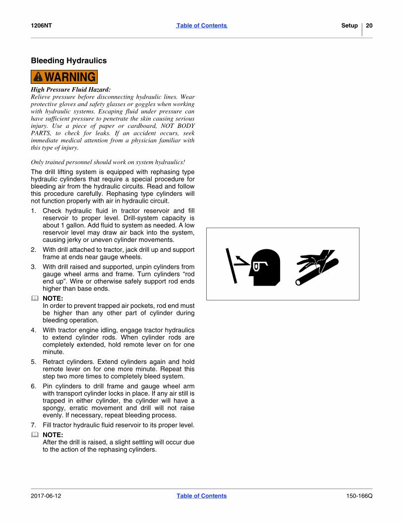
High Pressure Fluid Hazard:Relieve pressure before disconnecting hydraulic lines. Wearprotective gloves and safety glasses or goggles when workingwith hydraulic systems. Escaping fluid under pressure canhave sufficient pressure to penetrate the skin causing seriousinjury. Use a piece of paper or cardboard, NOT BODYPARTS, to check for leaks. If an accident occurs, seekimmediate medical attention from a physician familiar withthis type of injury.
Only trained personnel should work on system hydraulics!
The drill lifting system is equipped with rephasing typehydraulic cylinders that require a special procedure forbleeding air from the hydraulic circuits. Read and followthis procedure carefully. Rephasing type cylinders willnot function properly with air in hydraulic circuit.
1. Check hydraulic fluid in tractor reservoir and fillreservoir to proper level. Drill-system capacity isabout 1 gallon. Add fluid to system as needed. A lowreservoir level may draw air back into the system,causing jerky or uneven cylinder movements.
2. With drill attached to tractor, jack drill up and supportframe at ends near gauge wheels.
3. With drill raised and supported, unpin cylinders fromgauge wheel arms and frame. Turn cylinders “rodend up”. Wire or otherwise safely support rod endshigher than base ends.
NOTE:In order to prevent trapped air pockets, rod end mustbe higher than any other part of cylinder duringbleeding operation.
4. With tractor engine idling, engage tractor hydraulicsto extend cylinder rods. When cylinder rods arecompletely extended, hold remote lever on for oneminute.
5. Retract cylinders. Extend cylinders again and holdremote lever on for one more minute. Repeat thisstep two more times to completely bleed system.
6. Pin cylinders to drill frame and gauge wheel armwith transport cylinder locks in place. If any air still istrapped in either cylinder, the cylinder will have aspongy, erratic movement and drill will not raiseevenly. If necessary, repeat bleeding process.
7. Fill tractor hydraulic fluid reservoir to its proper level.
NOTE:After the drill is raised, a slight settling will occur dueto the action of the rephasing cylinders.
2017-06-12 Table of Contents 150-166Q

1206NT Table of Contents Setup 21
Rephasing CylindersThe lift cylinders may, after a period of time, get out oftime or phase. The effects of this can be seen when oneside of the drill is running too low or too high because itslift cylinder is either over extended or not retractedcompared to the other lift cylinder.
To rephase the cylinders, raise drill completely and holdtractor hydraulic lever on for a few seconds to givecylinders time to rephase.
Each time drill is raised out of ground momentarilyreverse hydraulic lever immediately after rephasing toallow cylinders to retract approximately 1/2 inch(12.5 mm). This will help in maintaining a level drill.
NOTE:Understand that having cylinders become graduallyout of time is different than having air trapped in thesystem from improper bleeding. Each condition iscorrected differently.
Leveling Drill1. Loosen locknuts (2) and adjust cylinder eyebolts (1)
so there is initially about 3 1/16 inch of threads abovemounting plate.
2. Raise drill with hydraulics until openers and coultersare 1 to 2 inches off the ground.
3. Measure height of coulter tube from ground on bothends of drill.
4. Adjust eyebolt to level drill from end to end.
5. Tighten nuts on eyebolts when drill is level.
13941
Figure 18Leveling Drill
2017-06-12 Table of Contents 150-166Q

1206NT Table of Contents 22
Appendix
Tire Size and Pressure 295/75/R x 22.5”, 65 psi (4.5 bar)
Torque Values Chart
94 6
25199m
BoltSize
Bolt Head IdentificationBoltSize
Bolt Head Identification
Grade 2 Grade 5 Grade 8 Class 5.8 Class 8.8 Class 10.9in-tpia N-mb N-m N-m mm x pitchc N-m N-m N-m1
4-20 7.4 11 M 5 X 0.81
4-28 8.5 13 18 M 6 X 1 7 11 155
16-18 15 24 33 M 8 X 1.25 17 26 365
16-24 17 26 37 M 8 X 1 18 28 393
8-16 27 42 59 M10 X 1.5 33 52 723
8-24 31 47 67 M10 X 0.75 39 61 857
16-14 43 67 95 M12 X 1.75 58 91 1257
16-20 49 75 105 M12 X 1.5 60 95 1301
2-13 66 105 145 M12 X 1 90 105 1451
2-20 75 115 165 M14 X 2 92 145 2009
16-12 95 150 210 M14 X 1.5 99 155 2159
16-18 105 165 235 M16 X 2 145 225 3155
8-11 130 205 285 M16 X 1.5 155 240 3355
8-18 150 230 325 M18 X 2.5 195 310 4053
4-10 235 360 510 M18 X 1.5 220 350 4853
4-16 260 405 570 M20 X 2.5 280 440 6107
8-9 225 585 820 M20 X 1.5 310 650 9007
8-14 250 640 905 M24 X 3 480 760 1050
1-8 340 875 1230 M24 X 2 525 830 1150
1-12 370 955 1350 M30 X 3.5 960 1510 2100
118-7 480 1080 1750 M30 X 2 1060 1680 2320
118-12 540 1210 1960 M36 X 3.5 1730 2650 3660
114-7 680 1520 2460 M36 X 2 1880 2960 4100
114-12 750 1680 2730
138-6 890 1990 3230 a. in-tpi = nominal thread diameter in inches-threads per inch
138-12 1010 2270 3680 b. N· m = newton-meters
112-6 1180 2640 4290
112-12 1330 2970 4820
c. mm x pitch = nominal thread diameter in mm x thread pitch
Torque tolerance + 0%, -15% of torquing values. Unless otherwise specified use torque values listed above.
5.8 8.8 10.9
25199
ft-lbd ft-lb ft-lb ft-lb ft-lb ft-lb5.6 8 12
6 10 14 5 8 11
11 17 25 12 19 27
13 19 27 13 21 29
20 31 44 24 39 53
22 35 49 29 45 62
32 49 70 42 67 93
36 55 78 44 70 97
49 76 105 66 77 105
55 85 120 68 105 150
70 110 155 73 115 160
79 120 170 105 165 230
97 150 210 115 180 245
110 170 240 145 230 300
170 265 375 165 260 355
190 295 420 205 325 450
165 430 605 230 480 665
185 475 670 355 560 780
250 645 910 390 610 845
275 705 995 705 1120 1550
355 795 1290 785 1240 1710
395 890 1440 1270 1950 2700
500 1120 1820 1380 2190 3220
555 1240 2010
655 1470 2380
745 1670 2710
870 1950 3160d. ft-lb = foot pounds
980 2190 3560
3 5 7
2017-06-12 Table of Contents 150-166Q

1206NT Table of Contents Appendix 23
Hydraulic Connectors and TorqueRefer to Figure 127 (a hypothetical fitting)
Leave any protective caps in place until immediately priorto making a connection.
(1)
NPT - National Pipe ThreadNote tapered threads, no cone/flare, and no O-ring. Apply liquid pipe sealant for hydraulic applications (do not use tape sealant, which can foul filters).
(2)
JIC - Joint Industry Conference (SAE J514)Note straight threads (4) and the 37 cone (5) on “M” fittings (or 37 flare on “F” fittings). Use no sealants (tape or liquid) on JIC fittings.
(3)
ORB - O-Ring Boss (SAE J514)Note straight threads (5) and elastomer O-Ring (7). Prior to installation, to prevent abrasion during tightening, lubricate O-Ring with clean hydraulic fluid. Use no sealants (tape or liquid) on JIC fittings.ORB fittings that need orientation, such as the ell depicted, also have a washer (8) and jam nut (9) (“adjustable thread port stud”). Back jam nut away from washer. Thread fitting into receptacle until O-Ring contacts seat. Unscrew fitting to desired orientation. Tighten jam nut to torque specification.
Fitting Torque ValuesFitting Ft•lbs N•m1/4 NPT 1.5-3.0 turns past finger tight9/16 JIC 18-20 24-279/16 ORB w/jam nut 12-16 16-229/16 ORB straight 18-24 24-323/4 JIC 27-39 37-533/4 ORB w/jam nut 20-30 27-413/4 ORB straight 27-43 37-58
2
5
4
98
75
3
1
Figure 19Hydraulic Connector
31282
2017-06-12 Table of Contents 150-166Q

1206NT Table of Contents Appendix 24
2017-06-12 Table of Contents 150-166Q

Table of Contents
Table of Contents

Great Plains, Mfg.1525 E. North St.P.O. Box 5060Salina, KS 67402